FLEXWELL Elliptical Waveguide 347-369 - RFS and circular waveguide configurations ... sometimes in...
23
www.rfsworld.com 347 MICROWAVE ANTENNA SYSTEMS 4 Introduction FLEXWELL ® Elliptical Waveguide Waveguides are used for the transmission of RF energy at microwave frequencies. The traditional rigid rectangular and circular waveguide configurations have been supplemented for the last 40 years by elliptical corrugated FLEXWELL ® transmission lines. Today, rectangular waveguides are mainly used for short connecting pieces, bends and twists, and sometimes in the form of UHF rectangular waveguides as very low loss TV antenna feeders Elliptical waveguides have helical corrugations and thus are suited for bending and winding on drums. These waveguides are recommended, due to their low attenuation and ease of handling, for microwave antenna feeders in the 2-40 GHz frequency range. For some frequency bands elliptical waveguides have been developed with extra low attenuation, achieved by overmoding. RADIO FREQUENCY SYSTEMS is the originator and designer of continuous seam welded corrugated transmission lines. FLEXWELL ® is RFS’s brand name for the highest quality, best performing, and most reliable elliptical waveguide in the industry. FLEXWELL ® designs are constantly proven successful in thousands of installations throughout the world. FLEXWELL ® elliptical waveguide is the ideal choice for microwave antenna systems and offers quality and reliability that you can depend on. Wide Selection FLEXWELL ® waveguides are available in a wide selection of frequency bands throughout the 3 GHz to 40 GHz microwave bands. The waveguides are equivalent in sizes to rectangular waveguide R32 (WR284) through R320 (WR28). Three versions of FLEXWELL ® elliptical waveguide are offered: FLEXWELL ® “Standard" waveguide, low VSWR “Premium" waveguide and “Overmoded waveguide". Standard and premium waveguide differ only in testing and guaranteed attainable VSWR. FLEXWELL ® “standard" waveguide is recommended for low and medium capacity radio relay systems, while FLEXWELL ® “premium" elliptical waveguide assemblies are recommended for high capacity radio systems. Overmoded waveguides offer exceptionally low attenuation characteristics compared with conventional waveguides. The waveguide operates above the cut-off frequency of higher order modes utilizing the lowest attenuation characteristics of the waveguide. Connectors for overmoded waveguide include filters which eliminate distortion due to mode conversion. FLEXWELL ® elliptical waveguide is constructed of pure electrolytic copper strip which uses a special RFS process to butt weld, corrugate and form into an approximate elliptical shape. The copper waveguide is covered with a black polyethylene jacket for protection during transport and installation. Special fire retardant jacketing is available for FLEXWELL ® waveguide on request. The manufacturing process of FLEXWELL ® elliptical waveguide is continuous and so the waveguide can be supplied in long lengths. Maximum Strength and Flexibility The corrugation design achieves high transverse stability, flexibility and crush strength for superior handling and forming at an installation. The inherent strength and flexibility of FLEXWELL ® waveguide allows a continuous length of waveguide to be run directly from a tower-mounted antenna to the equipment building, eliminating flange joint disconti- nuities and the use of bends and twists associated with a rigid rectangular waveguide system. Less Planning and Reduced Installation Cost FLEXWELL ® elliptical waveguide feeder systems requires less planning and reduces installation costs when compared to a feeder system using a rigid rectangular waveguide. FLEXWELL ® waveguide is available cut to length with factory attached connectors or in continuous lengths for termination in the field. Excellent Electrical Performance FLEXWELL ® elliptical waveguide has set an industry standard for excellent electrical performance. Each waveguide has been carefully designed for low loss and low VSWR in specific frequency bands. For optimum system performance, there is no substitute for FLEXWELL ® waveguide. Complete Feeder System from One Reliable Source In addition to waveguides, RFS offers a complete range of waveguide connectors, installation accessories, and high quality pressurization systems. This means no hassles, no multiple shipments and no out of sequence deliveries. With RFS, you get a total feeder system from one reliable source. Waveguide Theory Waveguides are used for the transmission of RF energy at microwave frequencies. The traditional rigid rectangular and circular waveguide configurations have been supple- mented for the last 40 years by elliptical corrugated Flexwell ® transmission lines. Today, rectangular waveguides are mainly used for short connecting pieces, bends and twists, and sometimes in the form of UHF rectangular waveguides as very low loss TV antenna feeders. Flexwell ® waveguides have helical corrugations and thus are suited for bending and winding on drums. These waveguides are recommended, due to their low attenuation and ease of handling, for microwave antenna feeders in the 2 to 40 GHz frequency range. For some frequency bands Flexwell® transmission lines have been developed with extra low attenuation, achieved by the use of overmoding. Radio Frequency Systems is the originator and designer of FLEXWELL® Elliptical Waveguides. It is a continuous seam welded corrugated transmission line.
Transcript of FLEXWELL Elliptical Waveguide 347-369 - RFS and circular waveguide configurations ... sometimes in...
www.rfsworld.com347
MIC
RO
WA
VE
AN
TENN
ASY
STEMS
4
Introduction
FLEXWELL® Elliptical Waveguide
Waveguides are used for the transmission of RFenergy at microwave frequencies. The traditional rigidrectangular and circular waveguide configurationshave been supplemented for the last 40 years byelliptical corrugated FLEXWELL® transmission lines.
Today, rectangular waveguides are mainly used forshort connecting pieces, bends and twists, andsometimes in the form of UHF rectangular waveguidesas very low loss TV antenna feeders
Elliptical waveguides have helical corrugations andthus are suited for bending and winding on drums.These waveguides are recommended, due to their lowattenuation and ease of handling, for microwaveantenna feeders in the 2-40 GHz frequency range.
For some frequency bands elliptical waveguides havebeen developed with extra low attenuation, achievedby overmoding.
RADIO FREQUENCY SYSTEMS is the originator anddesigner of continuous seam welded corrugatedtransmission lines. FLEXWELL® is RFS’s brand namefor the highest quality, best performing, and mostreliable elliptical waveguide in the industry.FLEXWELL® designs are constantly proven successfulin thousands of installations throughout the world.FLEXWELL® elliptical waveguide is the ideal choice formicrowave antenna systems and offers quality andreliability that you can depend on.
Wide SelectionFLEXWELL® waveguides are available in a wideselection of frequency bands throughout the 3 GHz to40 GHz microwave bands. The waveguides areequivalent in sizes to rectangular waveguide R32(WR284) through R320 (WR28).
Three versions of FLEXWELL® elliptical waveguide areoffered: FLEXWELL® “Standard" waveguide, lowVSWR “Premium" waveguide and “Overmodedwaveguide". Standard and premium waveguide differonly in testing and guaranteed attainable VSWR.FLEXWELL® “standard" waveguide is recommendedfor low and medium capacity radio relay systems,while FLEXWELL® “premium" elliptical waveguideassemblies are recommended for high capacity radiosystems. Overmoded waveguides offer exceptionallylow attenuation characteristics compared withconventional waveguides. The waveguide operatesabove the cut-off frequency of higher order modesutilizing the lowest attenuation characteristics of thewaveguide. Connectors for overmoded waveguideinclude filters which eliminate distortion due to modeconversion.
FLEXWELL® elliptical waveguide is constructed ofpure electrolytic copper strip which uses a specialRFS process to butt weld, corrugate and form into anapproximate elliptical shape. The copper waveguideis covered with a black polyethylene jacket forprotection during transport and installation.
Special fire retardant jacketing is available forFLEXWELL® waveguide on request. The manufacturingprocess of FLEXWELL® elliptical waveguide is
continuous and so the waveguide can be supplied inlong lengths.
Maximum Strength and FlexibilityThe corrugation design achieves high transversestability, flexibility and crush strength for superiorhandling and forming at an installation. The inherentstrength and flexibility of FLEXWELL® waveguideallows a continuous length of waveguide to be rundirectly from a tower-mounted antenna to theequipment building, eliminating flange joint disconti-nuities and the use of bends and twists associatedwith a rigid rectangular waveguide system.
Less Planning and Reduced Installation CostFLEXWELL® elliptical waveguide feeder systemsrequires less planning and reduces installation costswhen compared to a feeder system using a rigidrectangular waveguide. FLEXWELL® waveguide isavailable cut to length with factory attachedconnectors or in continuous lengths for termination inthe field.
Excellent Electrical PerformanceFLEXWELL® elliptical waveguide has set an industrystandard for excellent electrical performance. Eachwaveguide has been carefully designed for low lossand low VSWR in specific frequency bands. Foroptimum system performance, there is no substitutefor FLEXWELL® waveguide.
Complete Feeder System from One Reliable SourceIn addition to waveguides, RFS offers a completerange of waveguide connectors, installationaccessories, and high quality pressurization systems.This means no hassles, no multiple shipments and noout of sequence deliveries. With RFS, you get a totalfeeder system from one reliable source.
Waveguide Theory
Waveguides are used for the transmission of RF energy atmicrowave frequencies. The traditional rigid rectangularand circular waveguide configurations have been supple-mented for the last 40 years by elliptical corrugatedFlexwell® transmission lines.
Today, rectangular waveguides are mainly used for shortconnecting pieces, bends and twists, and sometimes inthe form of UHF rectangular waveguides as very low lossTV antenna feeders.
Flexwell® waveguides have helical corrugations and thus are suited forbending and winding on drums. These waveguides arerecommended, due to their low attenuation and easeof handling, for microwave antenna feeders in the 2to 40 GHz frequency range.
For some frequency bands Flexwell® transmissionlines have been developed with extra low attenuation,achieved by the use of overmoding.
Radio Frequency Systems is the originator anddesigner of FLEXWELL® Elliptical Waveguides. It is acontinuous seam welded corrugated transmission line.
www.rfsworld.com348
4
MIC
RO
WA
VE
AN
TEN
NA
SYST
EMS
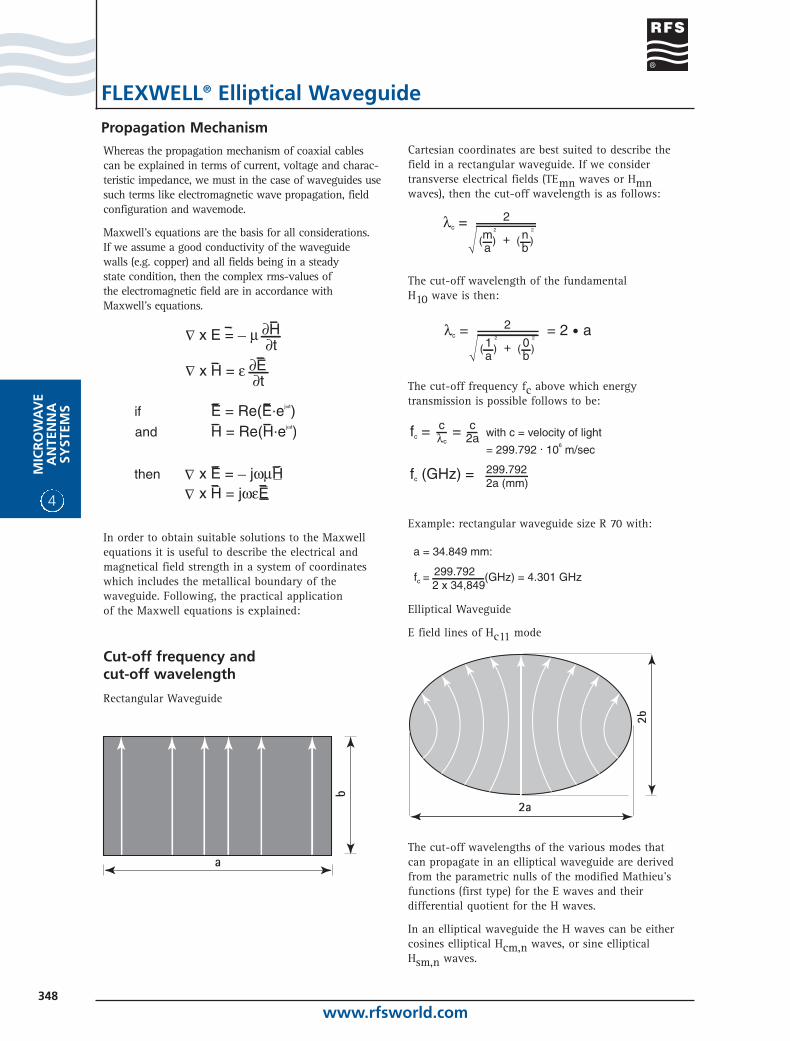
Cartesian coordinates are best suited to describe thefield in a rectangular waveguide. If we considertransverse electrical fields (TEmn waves or Hmnwaves), then the cut-off wavelength is as follows:
The cut-off wavelength of the fundamental H10 wave is then:
The cut-off frequency fc above which energytransmission is possible follows to be:
Example: rectangular waveguide size R 70 with:
Elliptical Waveguide
E field lines of Hc11 mode
The cut-off wavelengths of the various modes that can propagate in an elliptical waveguide are derivedfrom the parametric nulls of the modified Mathieu'sfunctions (first type) for the E waves and their differential quotient for the H waves.
In an elliptical waveguide the H waves can be eithercosines elliptical Hcm,n waves, or sine elliptical Hsm,n waves.
Whereas the propagation mechanism of coaxial cablescan be explained in terms of current, voltage and charac-teristic impedance, we must in the case of waveguides usesuch terms like electromagnetic wave propagation, field configuration and wavemode.
Maxwell's equations are the basis for all considerations. If we assume a good conductivity of the waveguide walls (e.g. copper) and all fields being in a steady state condition, then the complex rms-values of the electromagnetic field are in accordance with Maxwell's equations.
In order to obtain suitable solutions to the Maxwellequations it is useful to describe the electrical andmagnetical field strength in a system of coordinateswhich includes the metallical boundary of thewaveguide. Following, the practical application of the Maxwell equations is explained:
Cut-off frequency andcut-off wavelength
Rectangular Waveguide
λc = ma
2
+( )2
nb
( )2
fc = = with c = velocity of light
fc (GHz) =
= 299.792 . 106 m/sec
299.7922a (mm)
cλc
c2a
a = 34.849 mm:
fc = (GHz) = 4.301 GHz 299.7922 x 34,849
Propagation Mechanism
FLEXWELL® Elliptical Waveguide
www.rfsworld.com349
MIC
RO
WA
VE
AN
TENN
ASY
STEMS
4
Propagation Mechanism
FLEXWELL® Elliptical Waveguide
The fundamental wavemode is the Hc11 wave and its cut-off wavelength is as follows:
In this equation, the expression
is the eccentricity e and qc11 is the first parametric nullof the modified cosine elliptical Mathieu function of firsttype and first order.
Once cut-off frequency is known, then for any waveguidethe important terms: group velocity, phase velocity andwavelength can be calculated as follows:
With vgr - group velocityVph - phase velocitylH - wavelength in waveguidel - wavelength in free spacef - frequency
Frequency Range of Operation
a) Rectangular waveguide
Rectangular waveguides are used in the followingfrequency range of operation:
The upper frequency limit 1.9 fc is due to the fact thatabove that limit other wavemodes can exist. For the verycommon axis ratio of b over a = 0.5 the two wavemodesH01 and H20 can exist from 2.fcH10
and onwards.
Taking a safety factor of 0.1 fc gives the upper frequencylimit of 1.9fc for the fundamental wavemode.
b) Elliptical waveguide
Other than the Hc11 fundamental wavemode, the nextpossible modes are the Hs11 or Hc21 mode, dependentupon the axis ratio b over a.
For Flexwell® transmission lines with an axis ratio b overa = 0.52 (Which is the case for most types) the operatingfrequency range is as follows:
c) Overmoded elliptical waveguide
The energy is transmitted by the fundamental Hc11 mode. For use of the physical minimum of attenuation, theoperating frequency range has to be above the cutoff
frequencies of some higher modes. For example Flexwell®waveguide E015;
In case of discontinuities the higher modes Hs11, Hc21,Ec01 and Ec11 are excited and a part of energy isconverted from fundamental to higher modes. This effectresults in attenuation ripple versus frequency. Groupvelocity of higher modes is low compared to fundamentalmode, so mode reconversion to the dominant mode resultsin group delay distortion. The reconverted mode level isminimized by mode filters which are incorporated in theterminations. To minimize the effect of unwanted trappedmodes, a minimum length is recommended.
Noise Contribution
In order to achieve the lowest possible noise contributionof the waveguide system it is necessary to fulfill thefollowing requirements:
1 Low reflection factor (= good longitudinaluniformity)
2 Good mechanical and electrical contact
Requirement 1 is fulfilled by highly precise manufacturing and checking of waveguides and accessories, whereasrequirement 2 is guaranteed by construction and handlingmeasures, such as contact pressure, flanging with special tools, silver-plating of the contact surfaces, and avoidance of the use of tuning-screws.
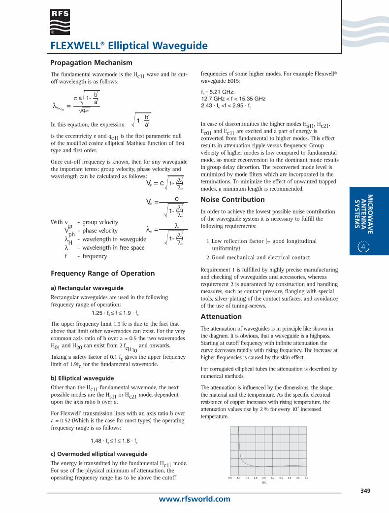
Attenuation
The attenuation of waveguides is in principle like shown inthe diagram. It is obvious, that a waveguide is a highpass.Starting at cutoff frequency with infinite attenuation thecurve decreases rapidly with rising frequency. The increase athigher frequencies is caused by the skin effect.
For corrugated elliptical tubes the attenuation is described bynumerical methods.
The attenuation is influenced by the dimensions, the shape,the material and the temperature. As the specific electricalresistance of copper increases with rising temperature, theattenuation values rise by 2 % for every 10o increasedtemperature.
www.rfsworld.com350
4
MIC
RO
WA
VE
AN
TEN
NA
SYST
EMS
FLEXWELL® Elliptical Waveguide
operating frequency band will be much moreattenuated than the fundamental mode.
The unwanted modes are mainly excited at disconti-nuities. The biggest change of the cross-section is thetransition from single-mode rectangular to overmodedelliptical waveguide.
The higher order modes are trapped in the ellipticalwaveguide between the connectors.So the waveguideperforms as a resonator.
This results in ripples of the signal over frequency,both in terms of amplitude and group delay. We haveobserved that group delay distortion has much lowerimpact on a link system than amplitude ripples.Therefore only the latter has to be observed.
To get low signal distortion, the conversion andreconversion between higher order modes andfundamental mode has to be minimized.
This is achieved by special connectors made byelectroforming. The applied NC technology allows theproduction of mendrals with prescribed mathematicalfunctions. Mode filters additionally minimize thesignal distortion.
Length of Waveguide and ModulationTechniques
The amplitude ripples are nonlinear distortions. Theydecrease with increasing waveguide length. The effectsare the same as known from filters after tuning: theydo not change after installation. That is whycorrection by an equalizer is possible.
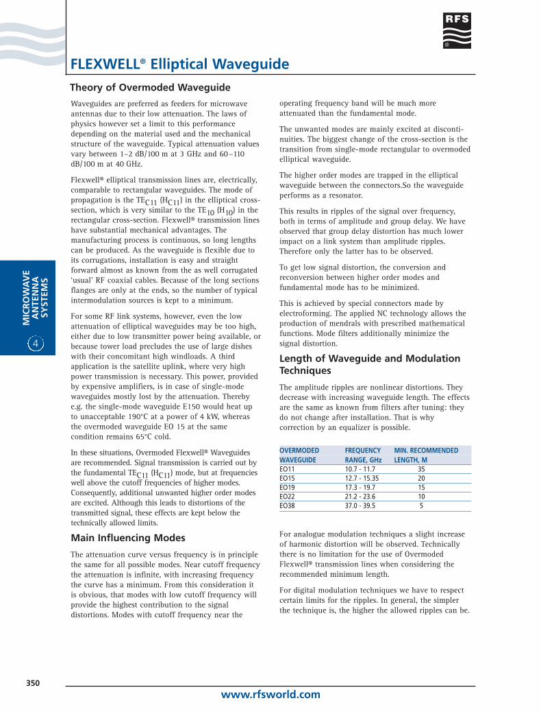
OVERMODED FREQUENCY MIN. RECOMMENDEDWAVEGUIDE RANGE, GHz LENGTH, MEO11 10.7 - 11.7 35EO15 12.7 - 15.35 20EO19 17.3 - 19.7 15EO22 21.2 - 23.6 10EO38 37.0 - 39.5 5
For analogue modulation techniques a slight increaseof harmonic distortion will be observed. Technicallythere is no limitation for the use of OvermodedFlexwell® transmission lines when considering therecommended minimum length.
For digital modulation techniques we have to respectcertain limits for the ripples. In general, the simplerthe technique is, the higher the allowed ripples can be.
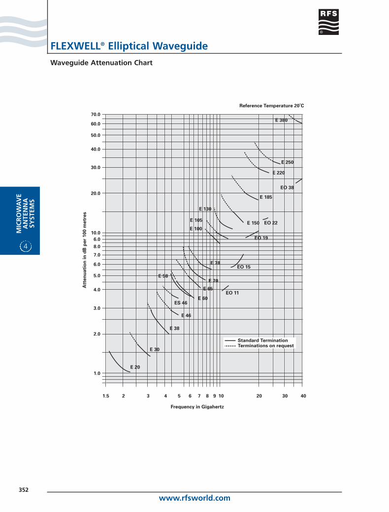
Waveguides are preferred as feeders for microwaveantennas due to their low attenuation. The laws ofphysics however set a limit to this performancedepending on the material used and the mechanicalstructure of the waveguide. Typical attenuation valuesvary between 1–2 dB/100 m at 3 GHz and 60–110dB/100 m at 40 GHz.
Flexwell® elliptical transmission lines are, electrically,comparable to rectangular waveguides. The mode ofpropagation is the TEC11 (HC11) in the elliptical cross-section, which is very similar to the TE10 (H10) in therectangular cross-section. Flexwell® transmission lineshave substantial mechanical advantages. Themanufacturing process is continuous, so long lengthscan be produced. As the waveguide is flexible due toits corrugations, installation is easy and straightforward almost as known from the as well corrugated‘usual’ RF coaxial cables. Because of the long sectionsflanges are only at the ends, so the number of typicalintermodulation sources is kept to a minimum.
For some RF link systems, however, even the lowattenuation of elliptical waveguides may be too high,either due to low transmitter power being available, orbecause tower load precludes the use of large disheswith their concomitant high windloads. A thirdapplication is the satellite uplink, where very highpower transmission is necessary. This power, providedby expensive amplifiers, is in case of single-modewaveguides mostly lost by the attenuation. Therebye.g. the single-mode waveguide E150 would heat upto unacceptable 190°C at a power of 4 kW, whereasthe overmoded waveguide EO 15 at the samecondition remains 65°C cold.
In these situations, Overmoded Flexwell® Waveguidesare recommended. Signal transmission is carried out bythe fundamental TEC11 (HC11) mode, but at frequencieswell above the cutoff frequencies of higher modes.Consequently, additional unwanted higher order modesare excited. Although this leads to distortions of thetransmitted signal, these effects are kept below thetechnically allowed limits.
Main Influencing Modes
The attenuation curve versus frequency is in principlethe same for all possible modes. Near cutoff frequencythe attenuation is infinite, with increasing frequencythe curve has a minimum. From this consideration itis obvious, that modes with low cutoff frequency willprovide the highest contribution to the signaldistortions. Modes with cutoff frequency near the
Theory of Overmoded Waveguide
www.rfsworld.com351
MIC
RO
WA
VE
AN
TENN
ASY
STEMS
4
FLEXWELL® Elliptical Waveguide
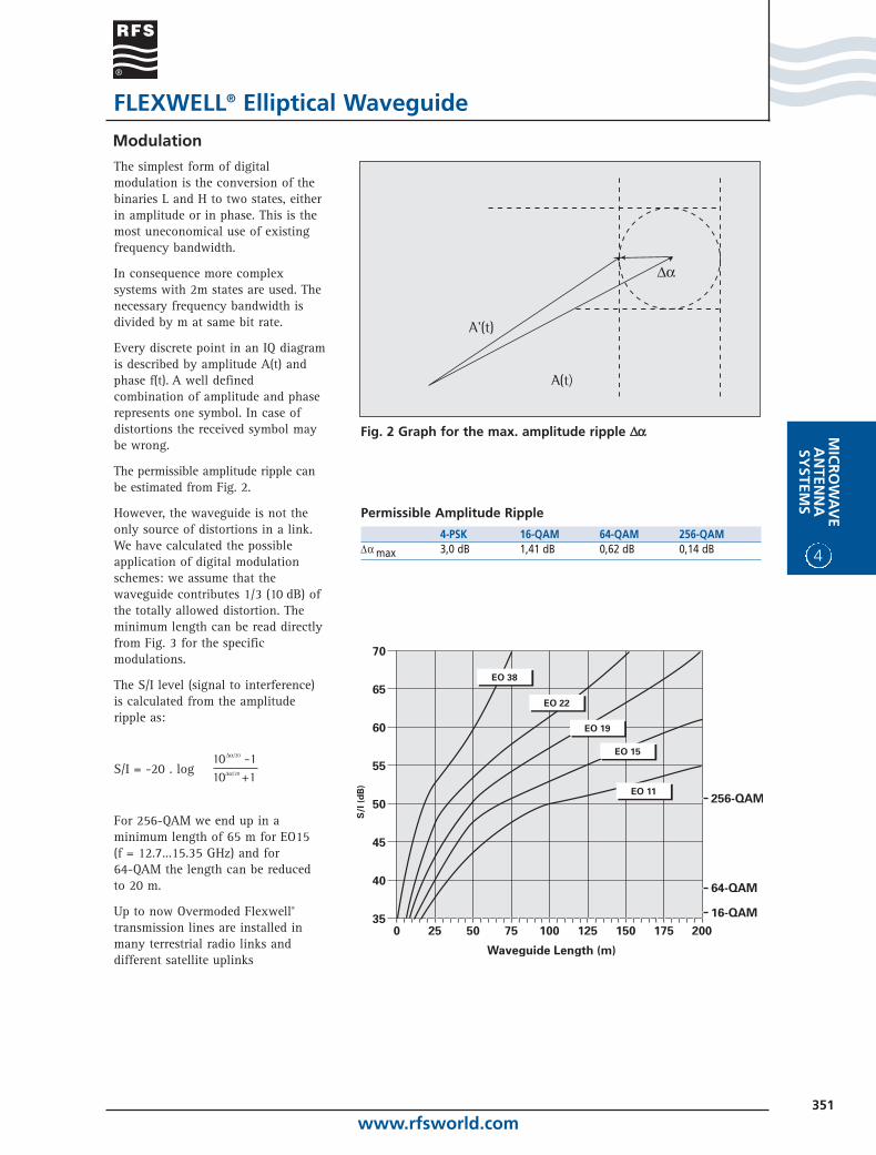
Modulation
A’(t)
³a
Fig. 2 Graph for the max. amplitude ripple DDaa
Permissible Amplitude Ripple
4-PSK 16-QAM 64-QAM 256-QAMD a max 3,0 dB 1,41 dB 0,62 dB 0,14 dB
The simplest form of digitalmodulation is the conversion of thebinaries L and H to two states, eitherin amplitude or in phase. This is themost uneconomical use of existingfrequency bandwidth.
In consequence more complexsystems with 2m states are used. Thenecessary frequency bandwidth isdivided by m at same bit rate.
Every discrete point in an IQ diagramis described by amplitude A(t) andphase f(t). A well definedcombination of amplitude and phaserepresents one symbol. In case ofdistortions the received symbol maybe wrong.
The permissible amplitude ripple canbe estimated from Fig. 2.
However, the waveguide is not theonly source of distortions in a link.We have calculated the possibleapplication of digital modulationschemes: we assume that thewaveguide contributes 1/3 (10 dB) ofthe totally allowed distortion. Theminimum length can be read directlyfrom Fig. 3 for the specificmodulations.
The S/I level (signal to interference)is calculated from the amplituderipple as:
S/I = -20 . log
For 256-QAM we end up in aminimum length of 65 m for EO15 (f = 12.7...15.35 GHz) and for 64-QAM the length can be reducedto 20 m.
Up to now Overmoded Flexwell®
transmission lines are installed inmany terrestrial radio links anddifferent satellite uplinks
Da
A(t)
A’(t)
10Da/20 -110Da/20 +1
www.rfsworld.com352
4
MIC
RO
WA
VE
AN
TEN
NA
SYST
EMS
FLEXWELL® Elliptical Waveguide
Waveguide Attenuation Chart
www.rfsworld.com353
MIC
RO
WA
VE
AN
TENN
ASY
STEMS
4
FLEXWELL® Elliptical Waveguide
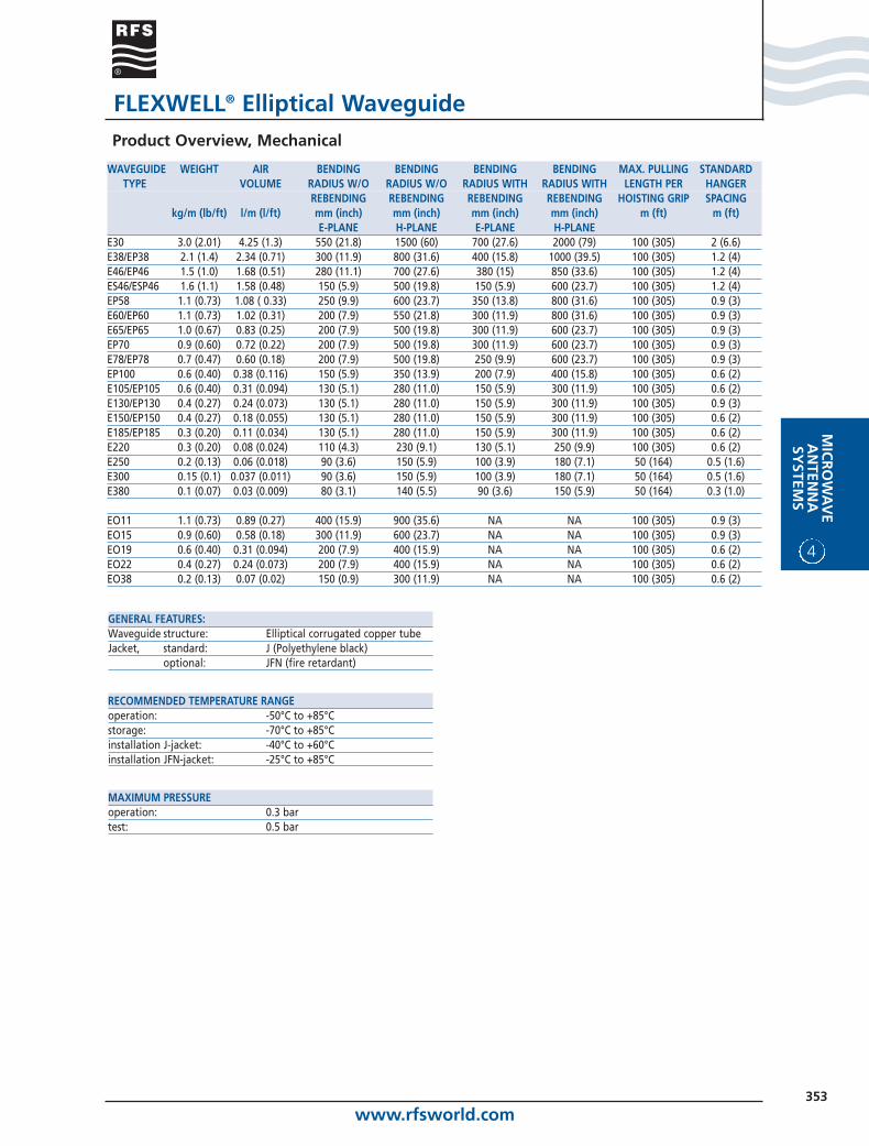
GENERAL FEATURES:Waveguide structure: Elliptical corrugated copper tubeJacket, standard: J (Polyethylene black)
optional: JFN (fire retardant)
RECOMMENDED TEMPERATURE RANGEoperation: -50°C to +85°Cstorage: -70°C to +85°Cinstallation J-jacket: -40°C to +60°Cinstallation JFN-jacket: -25°C to +85°C
MAXIMUM PRESSUREoperation: 0.3 bartest: 0.5 bar
WAVEGUIDE WEIGHT AIR BENDING BENDING BENDING BENDING MAX. PULLING STANDARDTYPE VOLUME RADIUS W/O RADIUS W/O RADIUS WITH RADIUS WITH LENGTH PER HANGER
REBENDING REBENDING REBENDING REBENDING HOISTING GRIP SPACINGkg/m (lb/ft) l/m (l/ft) mm (inch) mm (inch) mm (inch) mm (inch) m (ft) m (ft)
E-PLANE H-PLANE E-PLANE H-PLANEE30 3.0 (2.01) 4.25 (1.3) 550 (21.8) 1500 (60) 700 (27.6) 2000 (79) 100 (305) 2 (6.6)E38/EP38 2.1 (1.4) 2.34 (0.71) 300 (11.9) 800 (31.6) 400 (15.8) 1000 (39.5) 100 (305) 1.2 (4)E46/EP46 1.5 (1.0) 1.68 (0.51) 280 (11.1) 700 (27.6) 380 (15) 850 (33.6) 100 (305) 1.2 (4)ES46/ESP46 1.6 (1.1) 1.58 (0.48) 150 (5.9) 500 (19.8) 150 (5.9) 600 (23.7) 100 (305) 1.2 (4)EP58 1.1 (0.73) 1.08 ( 0.33) 250 (9.9) 600 (23.7) 350 (13.8) 800 (31.6) 100 (305) 0.9 (3)E60/EP60 1.1 (0.73) 1.02 (0.31) 200 (7.9) 550 (21.8) 300 (11.9) 800 (31.6) 100 (305) 0.9 (3)E65/EP65 1.0 (0.67) 0.83 (0.25) 200 (7.9) 500 (19.8) 300 (11.9) 600 (23.7) 100 (305) 0.9 (3)EP70 0.9 (0.60) 0.72 (0.22) 200 (7.9) 500 (19.8) 300 (11.9) 600 (23.7) 100 (305) 0.9 (3)E78/EP78 0.7 (0.47) 0.60 (0.18) 200 (7.9) 500 (19.8) 250 (9.9) 600 (23.7) 100 (305) 0.9 (3)EP100 0.6 (0.40) 0.38 (0.116) 150 (5.9) 350 (13.9) 200 (7.9) 400 (15.8) 100 (305) 0.6 (2)E105/EP105 0.6 (0.40) 0.31 (0.094) 130 (5.1) 280 (11.0) 150 (5.9) 300 (11.9) 100 (305) 0.6 (2)E130/EP130 0.4 (0.27) 0.24 (0.073) 130 (5.1) 280 (11.0) 150 (5.9) 300 (11.9) 100 (305) 0.9 (3)E150/EP150 0.4 (0.27) 0.18 (0.055) 130 (5.1) 280 (11.0) 150 (5.9) 300 (11.9) 100 (305) 0.6 (2)E185/EP185 0.3 (0.20) 0.11 (0.034) 130 (5.1) 280 (11.0) 150 (5.9) 300 (11.9) 100 (305) 0.6 (2)E220 0.3 (0.20) 0.08 (0.024) 110 (4.3) 230 (9.1) 130 (5.1) 250 (9.9) 100 (305) 0.6 (2)E250 0.2 (0.13) 0.06 (0.018) 90 (3.6) 150 (5.9) 100 (3.9) 180 (7.1) 50 (164) 0.5 (1.6)E300 0.15 (0.1) 0.037 (0.011) 90 (3.6) 150 (5.9) 100 (3.9) 180 (7.1) 50 (164) 0.5 (1.6)E380 0.1 (0.07) 0.03 (0.009) 80 (3.1) 140 (5.5) 90 (3.6) 150 (5.9) 50 (164) 0.3 (1.0)
EO11 1.1 (0.73) 0.89 (0.27) 400 (15.9) 900 (35.6) NA NA 100 (305) 0.9 (3)EO15 0.9 (0.60) 0.58 (0.18) 300 (11.9) 600 (23.7) NA NA 100 (305) 0.9 (3)EO19 0.6 (0.40) 0.31 (0.094) 200 (7.9) 400 (15.9) NA NA 100 (305) 0.6 (2)EO22 0.4 (0.27) 0.24 (0.073) 200 (7.9) 400 (15.9) NA NA 100 (305) 0.6 (2)EO38 0.2 (0.13) 0.07 (0.02) 150 (0.9) 300 (11.9) NA NA 100 (305) 0.6 (2)
Product Overview, Mechanical
www.rfsworld.com354
4
MIC
RO
WA
VE
AN
TEN
NA
SYST
EMS
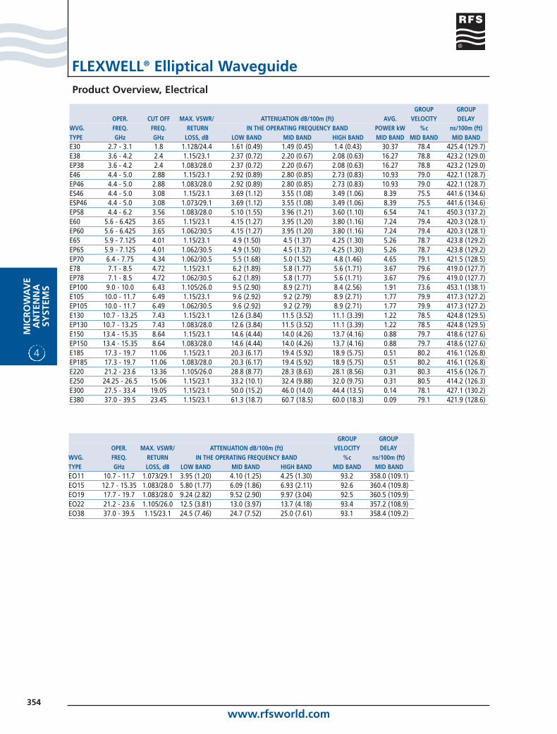
FLEXWELL® Elliptical WaveguideProduct Overview, Electrical
GROUP GROUPOPER. CUT OFF MAX. VSWR/ ATTENUATION dB/100m (ft) AVG. VELOCITY DELAY
WVG. FREQ. FREQ. RETURN IN THE OPERATING FREQUENCY BAND POWER kW %c ns/100m (ft)TYPE GHz GHz LOSS, dB LOW BAND MID BAND HIGH BAND MID BAND MID BAND MID BANDE30 2.7 - 3.1 1.8 1.128/24.4 1.61 (0.49) 1.49 (0.45) 1.4 (0.43) 30.37 78.4 425.4 (129.7)E38 3.6 - 4.2 2.4 1.15/23.1 2.37 (0.72) 2.20 (0.67) 2.08 (0.63) 16.27 78.8 423.2 (129.0)EP38 3.6 - 4.2 2.4 1.083/28.0 2.37 (0.72) 2.20 (0.67) 2.08 (0.63) 16.27 78.8 423.2 (129.0)E46 4.4 - 5.0 2.88 1.15/23.1 2.92 (0.89) 2.80 (0.85) 2.73 (0.83) 10.93 79.0 422.1 (128.7)EP46 4.4 - 5.0 2.88 1.083/28.0 2.92 (0.89) 2.80 (0.85) 2.73 (0.83) 10.93 79.0 422.1 (128.7)ES46 4.4 - 5.0 3.08 1.15/23.1 3.69 (1.12) 3.55 (1.08) 3.49 (1.06) 8.39 75.5 441.6 (134.6)ESP46 4.4 - 5.0 3.08 1.073/29.1 3.69 (1.12) 3.55 (1.08) 3.49 (1.06) 8.39 75.5 441.6 (134.6)EP58 4.4 - 6.2 3.56 1.083/28.0 5.10 (1.55) 3.96 (1.21) 3.60 (1.10) 6.54 74.1 450.3 (137.2)E60 5.6 - 6.425 3.65 1.15/23.1 4.15 (1.27) 3.95 (1.20) 3.80 (1.16) 7.24 79.4 420.3 (128.1)EP60 5.6 - 6.425 3.65 1.062/30.5 4.15 (1.27) 3.95 (1.20) 3.80 (1.16) 7.24 79.4 420.3 (128.1)E65 5.9 - 7.125 4.01 1.15/23.1 4.9 (1.50) 4.5 (1.37) 4.25 (1.30) 5.26 78.7 423.8 (129.2)EP65 5.9 - 7.125 4.01 1.062/30.5 4.9 (1.50) 4.5 (1.37) 4.25 (1.30) 5.26 78.7 423.8 (129.2)EP70 6.4 - 7.75 4.34 1.062/30.5 5.5 (1.68) 5.0 (1.52) 4.8 (1.46) 4.65 79.1 421.5 (128.5)E78 7.1 - 8.5 4.72 1.15/23.1 6.2 (1.89) 5.8 (1.77) 5.6 (1.71) 3.67 79.6 419.0 (127.7)EP78 7.1 - 8.5 4.72 1.062/30.5 6.2 (1.89) 5.8 (1.77) 5.6 (1.71) 3.67 79.6 419.0 (127.7)EP100 9.0 - 10.0 6.43 1.105/26.0 9.5 (2.90) 8.9 (2.71) 8.4 (2.56) 1.91 73.6 453.1 (138.1)E105 10.0 - 11.7 6.49 1.15/23.1 9.6 (2.92) 9.2 (2.79) 8.9 (2.71) 1.77 79.9 417.3 (127.2)EP105 10.0 - 11.7 6.49 1.062/30.5 9.6 (2.92) 9.2 (2.79) 8.9 (2.71) 1.77 79.9 417.3 (127.2)E130 10.7 - 13.25 7.43 1.15/23.1 12.6 (3.84) 11.5 (3.52) 11.1 (3.39) 1.22 78.5 424.8 (129.5)EP130 10.7 - 13.25 7.43 1.083/28.0 12.6 (3.84) 11.5 (3.52) 11.1 (3.39) 1.22 78.5 424.8 (129.5)E150 13.4 - 15.35 8.64 1.15/23.1 14.6 (4.44) 14.0 (4.26) 13.7 (4.16) 0.88 79.7 418.6 (127.6)EP150 13.4 - 15.35 8.64 1.083/28.0 14.6 (4.44) 14.0 (4.26) 13.7 (4.16) 0.88 79.7 418.6 (127.6)E185 17.3 - 19.7 11.06 1.15/23.1 20.3 (6.17) 19.4 (5.92) 18.9 (5.75) 0.51 80.2 416.1 (126.8)EP185 17.3 - 19.7 11.06 1.083/28.0 20.3 (6.17) 19.4 (5.92) 18.9 (5.75) 0.51 80.2 416.1 (126.8)E220 21.2 - 23.6 13.36 1.105/26.0 28.8 (8.77) 28.3 (8.63) 28.1 (8.56) 0.31 80.3 415.6 (126.7)E250 24.25 - 26.5 15.06 1.15/23.1 33.2 (10.1) 32.4 (9.88) 32.0 (9.75) 0.31 80.5 414.2 (126.3)E300 27.5 - 33.4 19.05 1.15/23.1 50.0 (15.2) 46.0 (14.0) 44.4 (13.5) 0.14 78.1 427.1 (130.2)E380 37.0 - 39.5 23.45 1.15/23.1 61.3 (18.7) 60.7 (18.5) 60.0 (18.3) 0.09 79.1 421.9 (128.6)
GROUP GROUPOPER. MAX. VSWR/ ATTENUATION dB/100m (ft) VELOCITY DELAY
WVG. FREQ. RETURN IN THE OPERATING FREQUENCY BAND %c ns/100m (ft)TYPE GHz LOSS, dB LOW BAND MID BAND HIGH BAND MID BAND MID BANDEO11 10.7 - 11.7 1.073/29.1 3.95 (1.20) 4.10 (1.25) 4.25 (1.30) 93.2 358.0 (109.1)EO15 12.7 - 15.35 1.083/28.0 5.80 (1.77) 6.09 (1.86) 6.93 (2.11) 92.6 360.4 (109.8)EO19 17.7 - 19.7 1.083/28.0 9.24 (2.82) 9.52 (2.90) 9.97 (3.04) 92.5 360.5 (109.9)EO22 21.2 - 23.6 1.105/26.0 12.5 (3.81) 13.0 (3.97) 13.7 (4.18) 93.4 357.2 (108.9)EO38 37.0 - 39.5 1.15/23.1 24.5 (7.46) 24.7 (7.52) 25.0 (7.61) 93.1 358.4 (109.2)
www.rfsworld.com355
MIC
RO
WA
VE
AN
TENN
ASY
STEMS
4
FLEXWELL® Elliptical Waveguide
Packing information
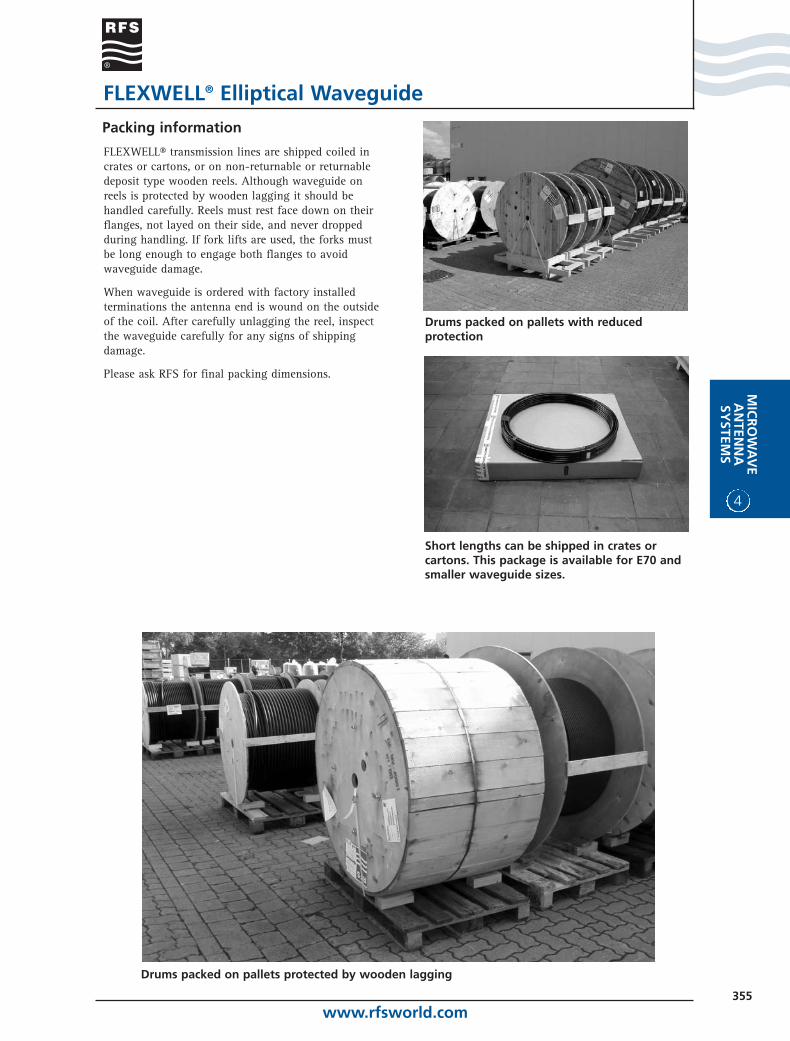
FLEXWELL® transmission lines are shipped coiled incrates or cartons, or on non-returnable or returnabledeposit type wooden reels. Although waveguide onreels is protected by wooden lagging it should behandled carefully. Reels must rest face down on theirflanges, not layed on their side, and never droppedduring handling. If fork lifts are used, the forks mustbe long enough to engage both flanges to avoidwaveguide damage.
When waveguide is ordered with factory installedterminations the antenna end is wound on the outsideof the coil. After carefully unlagging the reel, inspectthe waveguide carefully for any signs of shippingdamage.
Please ask RFS for final packing dimensions.
Drums packed on pallets protected by wooden lagging
Drums packed on pallets with reducedprotection
Short lengths can be shipped in crates orcartons. This package is available for E70 andsmaller waveguide sizes.
www.rfsworld.com356
4
MIC
RO
WA
VE
AN
TEN
NA
SYST
EMS
FLEXWELL® Elliptical Waveguide
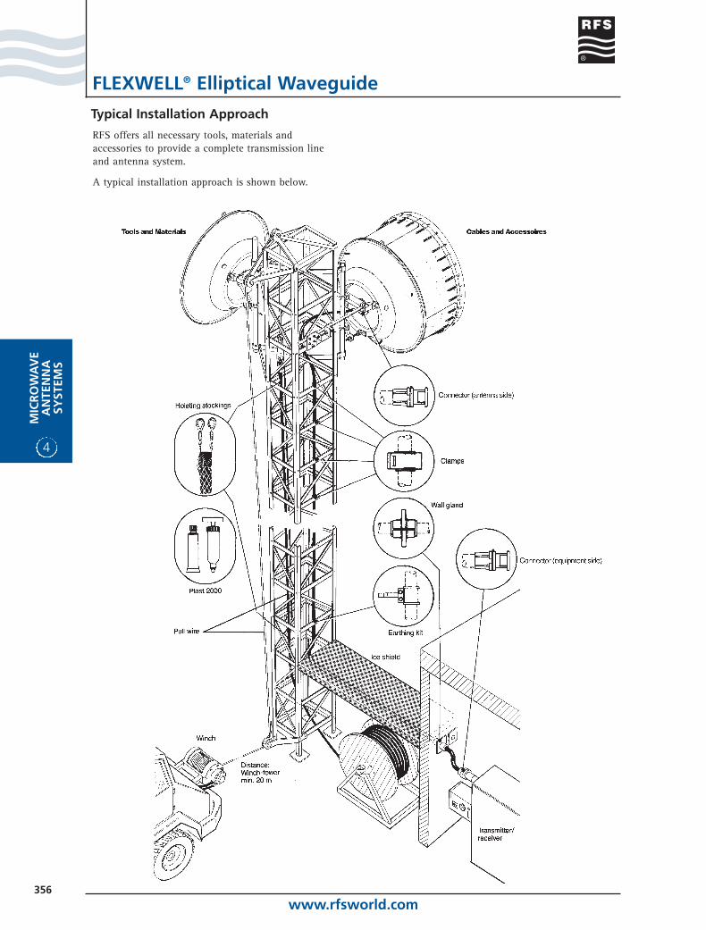
Typical Installation Approach
RFS offers all necessary tools, materials andaccessories to provide a complete transmission lineand antenna system.
A typical installation approach is shown below.
www.rfsworld.com357
MIC
RO
WA
VE
AN
TENN
ASY
STEMS
4
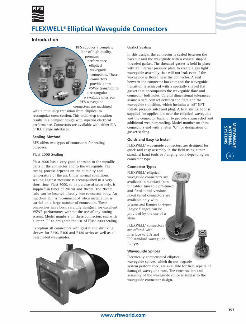
RFS supplies a completeline of high quality,
premiumperformanceellipticalwaveguideconnectors. Theseconnectorsprovide a low
VSWR transition toa rectangular
waveguide interface.RFS waveguide
connectors are machinedwith a multi-step transition from elliptical torectangular cross-section. This multi-step transitionresults in a compact design with superior electricalperformance. Connectors are available with either EIAor IEC flange interfaces.
Sealing Method
RFS offers two types of connectors for sealingpurposes.
Plast 2000 Sealing
Plast 2000 has a very good adhesion to the metallicparts of the connector and to the waveguide. Thecuring process depends on the humidity andtemperature of the air. Under normal conditions,sealing against moisture is accomplished in a veryshort time. Plast 2000, to be purchased separately, issupplied in tubes of 20ccm and 70ccm. The 20ccmtube can be inserted directly into connector body. Aninjection gun is recommended when installation iscarried on a large number of connectors. Theseconnectors have been carefully designed for excellentVSWR performance without the use of any tuningscrews. Model numbers on these connectors end witha letter “P" to designate the use of Plast 2000 sealing.
Exception all connectors with gasket and shrinkingsleeves for E250, E300 and E380 series as well as allovermoded waveguides.
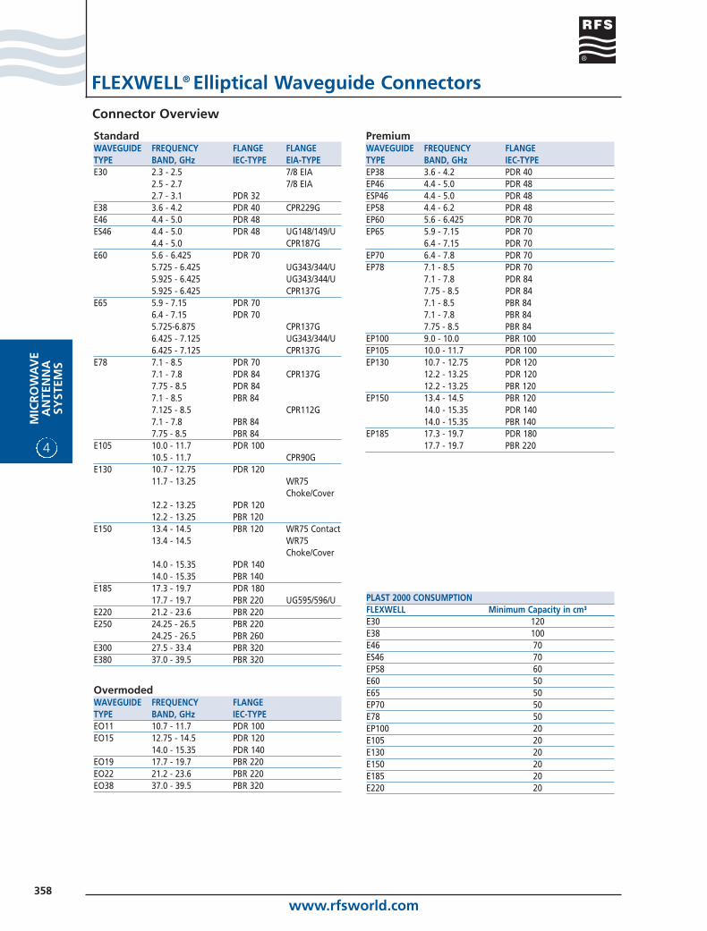
Gasket Sealing
In this design, the connector is sealed between thebacknut and the waveguide with a conical shapedthreaded gasket. The threaded gasket is held in placewith an internal pressure plate to create a gas tightwaveguide assembly that will not leak even if thewaveguide is flexed near the connector. A sealbetween the connector backnut and the waveguidetransition is achieved with a specially shaped flatgasket that encompasses the waveguide flare andconnector bolt holes. Careful dimensional tolerancesassure a safe contact between the flare and thewaveguide transition, which includes a 1/8” NPTfemale pressure inlet and plug. A heat shrink boot issupplied for application over the elliptical waveguideand the connector backnut to provide strain relief andadditional weatherproofing. Model number on theseconnectors end with a letter “G" for designation ofgasket sealing.
Quick and Easy to Install
FLEXWELL® waveguide connectors are designed forquick and easy assembly in the field using eitherstandard hand tools or flanging tools depending onconnector type.
Connector Types
FLEXWELL® ellipticalwaveguide connectors areavailable in standard (non-tuneable), tuneable pre-tunedand fixed tuned versions.Fixed tuned connectors areavailable only withpressurized flanges (P-type).U-type flanges can beprovided by the use of ashim.
FLEXWELL® connectorsare offered withinterface to EIA andIEC standard waveguideflanges.
Waveguide Splices
Electrically compensated ellipticalwaveguide splices, which do not degradesystem performance, are available for field repairs ofdamaged waveguide runs. The construction andassembly of the waveguide splice is similar to thewaveguide connector design.
Introduction
FLEXWELL® Elliptical Waveguide Connectors
www.rfsworld.com358
4
MIC
RO
WA
VE
AN
TEN
NA
SYST
EMS
Connector Overview
FLEXWELL® Elliptical Waveguide Connectors
StandardWAVEGUIDE FREQUENCY FLANGE FLANGE TYPE BAND, GHz IEC-TYPE EIA-TYPEE30 2.3 - 2.5 7/8 EIA
2.5 - 2.7 7/8 EIA2.7 - 3.1 PDR 32
E38 3.6 - 4.2 PDR 40 CPR229GE46 4.4 - 5.0 PDR 48ES46 4.4 - 5.0 PDR 48 UG148/149/U
4.4 - 5.0 CPR187GE60 5.6 - 6.425 PDR 70
5.725 - 6.425 UG343/344/U5.925 - 6.425 UG343/344/U5.925 - 6.425 CPR137G
E65 5.9 - 7.15 PDR 706.4 - 7.15 PDR 705.725-6.875 CPR137G6.425 - 7.125 UG343/344/U6.425 - 7.125 CPR137G
E78 7.1 - 8.5 PDR 707.1 - 7.8 PDR 84 CPR137G7.75 - 8.5 PDR 847.1 - 8.5 PBR 847.125 - 8.5 CPR112G7.1 - 7.8 PBR 847.75 - 8.5 PBR 84
E105 10.0 - 11.7 PDR 10010.5 - 11.7 CPR90G
E130 10.7 - 12.75 PDR 12011.7 - 13.25 WR75
Choke/Cover12.2 - 13.25 PDR 12012.2 - 13.25 PBR 120
E150 13.4 - 14.5 PBR 120 WR75 Contact13.4 - 14.5 WR75
Choke/Cover14.0 - 15.35 PDR 14014.0 - 15.35 PBR 140
E185 17.3 - 19.7 PDR 18017.7 - 19.7 PBR 220 UG595/596/U
E220 21.2 - 23.6 PBR 220E250 24.25 - 26.5 PBR 220
24.25 - 26.5 PBR 260E300 27.5 - 33.4 PBR 320E380 37.0 - 39.5 PBR 320
PremiumWAVEGUIDE FREQUENCY FLANGETYPE BAND, GHz IEC-TYPEEP38 3.6 - 4.2 PDR 40 EP46 4.4 - 5.0 PDR 48ESP46 4.4 - 5.0 PDR 48EP58 4.4 - 6.2 PDR 48EP60 5.6 - 6.425 PDR 70EP65 5.9 - 7.15 PDR 70
6.4 - 7.15 PDR 70EP70 6.4 - 7.8 PDR 70EP78 7.1 - 8.5 PDR 70
7.1 - 7.8 PDR 847.75 - 8.5 PDR 847.1 - 8.5 PBR 847.1 - 7.8 PBR 847.75 - 8.5 PBR 84
EP100 9.0 - 10.0 PBR 100EP105 10.0 - 11.7 PDR 100EP130 10.7 - 12.75 PDR 120
12.2 - 13.25 PDR 12012.2 - 13.25 PBR 120
EP150 13.4 - 14.5 PBR 12014.0 - 15.35 PDR 14014.0 - 15.35 PBR 140
EP185 17.3 - 19.7 PDR 18017.7 - 19.7 PBR 220
OvermodedWAVEGUIDE FREQUENCY FLANGE TYPE BAND, GHz IEC-TYPEEO11 10.7 - 11.7 PDR 100EO15 12.75 - 14.5 PDR 120
14.0 - 15.35 PDR 140EO19 17.7 - 19.7 PBR 220EO22 21.2 - 23.6 PBR 220EO38 37.0 - 39.5 PBR 320
PLAST 2000 CONSUMPTIONFLEXWELL Minimum Capacity in cm³E30 120E38 100E46 70ES46 70EP58 60E60 50E65 50EP70 50E78 50EP100 20E105 20E130 20E150 20E185 20E220 20
www.rfsworld.com359
MIC
RO
WA
VE
AN
TENN
ASY
STEMS
4
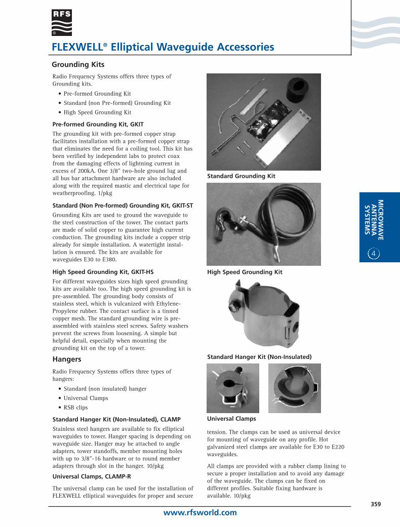
tension. The clamps can be used as universal devicefor mounting of waveguide on any profile. Hotgalvanized steel clamps are available for E30 to E220waveguides.
All clamps are provided with a rubber clamp lining tosecure a proper installation and to avoid any damageof the waveguide. The clamps can be fixed ondifferent profiles. Suitable fixing hardware isavailable. 10/pkg
Grounding Kits
FLEXWELL® Elliptical Waveguide Accessories
Radio Frequency Systems offers three types ofGrounding kits.
• Pre-formed Grounding Kit
• Standard (non Pre-formed) Grounding Kit
• High Speed Grounding Kit
Pre-formed Grounding Kit, GKIT
The grounding kit with pre-formed copper strapfacilitates installation with a pre-formed copper strapthat eliminates the need for a coiling tool. This kit hasbeen verified by independent labs to protect coaxfrom the damaging effects of lightning current inexcess of 200kA. One 3/8" two-hole ground lug andall bus bar attachment hardware are also includedalong with the required mastic and electrical tape forweatherproofing. 1/pkg
Standard (Non Pre-formed) Grounding Kit, GKIT-ST
Grounding Kits are used to ground the waveguide tothe steel construction of the tower. The contact partsare made of solid copper to guarantee high currentconduction. The grounding kits include a copper stripalready for simple installation. A watertight instal-lation is ensured. The kits are available forwaveguides E30 to E380.
High Speed Grounding Kit, GKIT-HS
For different waveguides sizes high speed groundingkits are available too. The high speed grounding kit ispre-assembled. The grounding body consists ofstainless steel, which is vulcanized with Ethylene-Propylene rubber. The contact surface is a tinnedcopper mesh. The standard grounding wire is pre-assembled with stainless steel screws. Safety washersprevent the screws from loosening. A simple buthelpful detail, especially when mounting thegrounding kit on the top of a tower.
Hangers
Radio Frequency Systems offers three types ofhangers:
• Standard (non insulated) hanger
• Universal Clamps
• RSB clips
Standard Hanger Kit (Non-Insulated), CLAMP
Stainless steel hangers are available to fix ellipticalwaveguides to tower. Hanger spacing is depending onwaveguide size. Hanger may be attached to angleadapters, tower standoffs, member mounting holeswith up to 3/8"-16 hardware or to round memberadapters through slot in the hanger. 10/pkg
Universal Clamps, CLAMP-R
The universal clamp can be used for the installation ofFLEXWELL elliptical waveguides for proper and secure
Standard Grounding Kit
High Speed Grounding Kit
Standard Hanger Kit (Non-Insulated)
Universal Clamps
www.rfsworld.com360
4
MIC
RO
WA
VE
AN
TEN
NA
SYST
EMS
FLEXWELL® Elliptical Waveguide Accessories
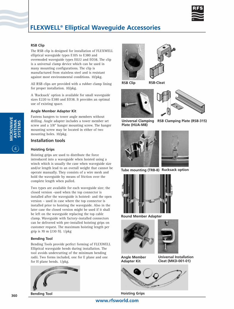
RSB Clip
Angle MemberAdapter Kit
Hoisting Grips
RSB Clip
The RSB clip is designed for installation of FLEXWELLelliptical waveguide types E105 to E380 andovermoded waveguide types E022 and EO38. The clipis a universal clamp device which can be used inmany mounting configurations. The clip ismanufactured from stainless steel and is resistantagainst most environmental conditions. 10/pkg.
All RSB clips are provided with a rubber clamp liningfor proper installation. 10/pkg.
A 'Rucksack' option is available for small waveguidesizes E220 to E380 and EO38. It provides an optimaluse of existing space.
Angle Member Adapter Kit
Fastens hangers to tower angle members withoutdrilling. Angle adapter includes a tower member setscrew and a 3/8" hanger mounting screw. The hangermounting screw may be located in either of twomounting holes. 10/pkg.
Installation tools
Hoisting Grips
Hoisting grips are used to distribute the forceintroduced into a waveguide when hoisted using awinch which is usually the case when waveguide sizeand/or length lead to an overall weight that cannot beoperate manually. They consists of a wire mesh andhold the waveguide by means of friction over thecomplete length when pulled.
Two types are available for each waveguide size; theclosed version -used when the top connector isinstalled after the waveguide is hoisted- and the openversion – used in case where the top connector isinstalled prior to hoisting the waveguide. Also in thelater case the closed version might be used if it shallbe left on the waveguide replacing the top cableclamp. Waveguide with factory-installed connectorscan be delivered with pre-installed hoisting grips oncustomer request. The maximum hoisting length pergrip is 70 m (230 ft). 1/pkg
Bending Tool
Bending Tools provide perfect forming of FLEXWELLElliptical waveguide bends during installation. The tool avoids undercutting of the minimum bending radii. Two forms included, one for E plane and one for H plane bends. 1/pkg.
Bending Tool
Tube mounting (TRB-8)
Round Member Adapter
RSB-Cleat
Rucksack option
RSB Clamping Plate (RSB-315)Universal ClampingPlate (HUA-M8)
Universal InstallationCleat (MKD-001-01)

www.rfsworld.com361
MIC
RO
WA
VE
AN
TENN
ASY
STEMS
4
Flanging tools
Mini Tools
Basic Tool w/o die Compact Tool with die
FLEXWELL® Elliptical Waveguide Accessories
Flanging tools* have been developed to simplify theinstallation and thus reducing costs. The flangingtools from RFS are designed to produce a perfecttermination every time eliminating the need for anyreworking of the termination.
The tool consists of two parts. The tool and a die.
Different types of flanging tools are availabledepending on waveguide sizes:
• A Basic Tool for E30 to E150
• A Compact Tool for E105 to E380
• A Mini Tool for E185 to E380
A separate die is required for each waveguide size.* Not applicable for gasket type connectors
Round Member Tower Stand-off Kit
Constructed of heavy stainless steel, the stand-offsprovide 2-1/2" (63 mm) tower clearance to hangerswhen running waveguide over tower cross members,flanges and other tower obstacles. The kit consists often stainless steel tower stand-offs with stainless steelhardware. Use with threaded rod kit for additionaltower clearance. 1/pkg.
ORDERING INFORMATIONFEED-THROUGH ENTRY PANELSModel DescriptionFTP4-1X1 Feed through entry panel, 102mm (4”), 1 hole, 1x1FTP4-1X2 Feed through entry panel, 102mm (4”), 2 holes, 1x2FTP4-1X3 Feed through entry panel, 102mm (4”), 3 holes, 1x3FTP4-1X4 Feed through entry panel, 102mm (4”), 4 holes, 1x4FTP4-2X2 Feed through entry panel, 102mm (4”), 4 holes, 2x2FTP4-2X3 Feed through entry panel, 102mm (4”), 6 holes, 2x3FTP4-2X4 Feed through entry panel, 102mm (4”), 8 holes, 2x4FTP4-2X5 Feed through entry panel, 102mm (4”), 10 holes, 2x5FTP4-2X6 Feed through entry panel, 102mm (4”), 12 holes, 2x6FTP4-3X3 Feed through entry panel, 102mm (4”), 9 holes, 3x3FTP4-3X4 Feed through entry panel, 102mm (4”), 12 holes, 3x4
PORT COVER FOR ENTRY PANELSModel DescriptionFTP4-PC Port cover for 102mm (4”) entry panel
WF Series
WFT Series
Wall / Roof Feed Through
RFS offers two types of Wall/Roof feed throughsystems:
WFT Series Single Entry Feed Through
The single entry feed through system seals ellipticalwaveguide at building entrance. It consists of arubber boot and aluminum split fastening ring.
WF Series Standard Feed Through
The standard feed through system consists of a rubberboot, stainless steel clamp, fixing and sealingmaterial.
Waveguide Repair Kit
The repair kit is used to mend a small puncture holein the outer conductor of copper elliptical waveguide.The kit is not intended to repair crushed waveguide.Supplied components include copper foil wrap (1-1/2"dia.), adhesive tape, sanding cloth and wrap-aroundheat shrink sleeve. Required tools are; sharp knife,alcohol cleaner, heat gun or wide flame torch. 1/pkg.
WFS Series
FTP4 Series
BOOT 4” Series
www.rfsworld.com362
4
MIC
RO
WA
VE
AN
TEN
NA
SYST
EMS
FLEXWELL® Elliptical Waveguide
Connector & Accessory Reference Guide (See installation hardware on separate table)
E30 (2.7 - 3.1 GHz)Connector, PDR32, 2.7 - 3.1 GHz, Plast 2000 D32-030FP-UConnector, 7/8" EIA (GB), 2.5 - 2.7 GHz, Gasket 78EB-030FGConnector, 7/8" EIA (GP), 2.5 - 2.7 GHz, Gasket 78E-030FGSplice, 2.5 - 3.1 GHz, Gasket SPLICE-030Grounding Kit, Pre-formed Copper Strap-Factory attached Lug-24" Wire GKIT-24-030Grounding Kit, Pre-formed Copper Strap-Field attachable Lug-60" Wire GKIT-60-030Grounding Kit GKIT-ST-030Standard Hanger Kit, Non-insulated, stainless steel CLAMP-030Universal clamp with clamp lining for angle iron 50 mm (1.9 inch) CLAMP-R-030-A5Universal clamp with clamp lining for angle iron 80 mm (3.2 inch) CLAMP-R-030-A8Universal clamp with clamp lining for anchor bars with 18 to 22 mm (0.7 to 0.8 inch) slot CLAMP-R-030-ACUniversal clamp with clamp lining for flat iron up to 15 mm (0.6 inch) CLAMP-R-030-AFHoisting Grip, Lace-Up, single loop configuration HOIST1-030LHoisting grip, Lace-Up, two loop configuration HOIST2-L09Wall/Roof Feed-Through, Aluminum plate WFT-030Flanging die, basic Tool FDIE-B030*Basic Tool FTOOL-B020030*
E38 SERIES (3.6 - 4.2 GHz)Connector, PDR40, 3.6 - 4.2 GHz, Plast 2000 D40-038FP-UConnector, CPR229G, 3.6 - 4.2 GHz, Gasket, only E38 C229-038TGSplice, N/A, 3.4 - 4.2 GHz, Gasket SPLICE-038Grounding Kit, Pre-formed Copper Strap-Factory attached Lug-24" Wire GKIT-24-038Grounding Kit, Pre-formed Copper Strap-Field attachable Lug-60" Wire GKIT-60-038Grounding kit GKIT-ST-038Universal clamp with clamp lining CLAMP-R-038Hoisting grip, Lace-Up, two loop configuration HOIST2-L08Bending Tool Kit BENDTOOL-038060Wall/Roof Feed-Through, Aluminum plate WFT-038Wall/Roof Feed-Through, Stainless Steel plate WF-038Feed Through Boot Assembly w/1 hole - 4" BOOT4-038Flanging die, basic tool FDIE-B038*Basic Tool FTOOL-B038150*
E46 SERIES (4.4 - 5.0 GHz)Connector, PDR48, 4.4 - 5.0 GHz, Plast 2000 D48-046FPSplice, N/A, 4.4 - 5.0 GHz, Gasket SPLICE-046Grounding Kit GKIT-ST-046Universal clamp with clamp lining CLAMP-R-046Hoisting grip, Lace-Up, two loop configuration HOIST2-L07Bending Tool Kit BENDTOOL-038060Wall/Roof Feed-Through, Aluminum plate WFT-046Wall/Roof Feed-Through, Stainless Steel plate WF-046Flanging die, basic Tool FDIE-B046*Basic Tool FTOOL-B038150*
ES46 SERIES (4.4-5.0 GHz)Connector, PDR48, 4.4 - 5.0 GHz, Plast 2000 D48-S46FPConnector, CPR187G, 4.4 - 5.0 GHz, Gasket, only ES46 C187-S46FGConnector, CPR187G, 4.4 - 5.0 GHz, Gasket, only ES46 C187-S46TGConnector, UG-148/149/U, 4.4 - 5.0 GHz, Gasket G148-S46TGSplice, N/A, 4.4 - 5.0 GHz, Gasket SPLICE-S46Grounding Kit, Pre-formed Copper Strap-Factory attached Lug-24" Wire GKIT-24-046Grounding Kit, Pre-formed Copper Strap-Field attachable Lug-60" Wire GKIT-60-046
ES46 SERIES (4.4-5.0 GHz) CONT’DGrounding Kit GKIT-ST-S46Standard Hanger Kit, Non-insulated, stainless steel CLAMP-046Universal clamp with clamp lining CLAMP-R-S046Hoisting Grip, Lace-Up, single loop configuration HOIST1-046LHoisting grip, Lace-Up, two loop configuration HOIST2-L07Bending Tool Kit BENDTOOL-038060Wall/Roof Feed-Through, Aluminum plate WFT-046Wall/Roof Feed-Through, Stainless Steel plate WF-046Feed Through Boot Assembly w/1 hole - 4" BOOT4-046Flanging die, basic Tool FDIE-BS46*Basic Tool FTOOL-B038150*
EP58 (4.4 - 6.2 GHz)Connector, PDR48, 4.4 - 6.2 GHz, Plast 2000 D48-058FPGrounding Kit GKIT-ST-058Universal clamp with clamp lining CLAMP-R-058Hoisting grip, Lace-Up, two loop configuration HOIST2-L06Bending Tool Kit BENDTOOL-038060Wall/Roof Feed-Through, Stainless Steel plate WF-058/060Flanging die, basic Tool FDIE-B058*Basic Tool for E38 to E150 FTOOL-B038150*
E60 SERIES (5.6 - 6.425 GHz)Connector, CPR137G, 5.725 - 6.425 GHz, Gasket, only E60 C137-060FGConnector, PDR70, 5.6 - 6.425 GHz, Plast 2000 D70-060FP-WConnector, CPR137G, 5.925 - 6.425 GHz, Gasket,only E60 C137-060TGConnector, UG-343/344/U, 5.925 - 6.425 GHz, Gasket G343-060FGConnector, UG-343/344/U, 5.925 - 6.425 GHz, Gasket G343-060TGGrounding Kit, Pre-formed Copper Strap-Factory attached Lug-24" Wire GKIT-24-060Grounding Kit, Pre-formed Copper Strap-Field attachable Lug-60" Wire GKIT-60-060Grounding Kit GKIT-ST-060Standard Hanger Kit, Non-insulated, stainless steel CLAMP-060Universal clamp with clamp lining CLAMP-R-060Hoisting Grip, Lace-Up, single loop configuration HOIST1-060LHoisting grip, Lace-Up, two loop configuration HOIST2-L06Bending Tool Kit BENDTOOL-038060Bending Tool Kit BENDTOOL-058078Wall/Roof Feed-Through, Aluminum plate WFT-060Wall/Roof Feed-Through, Stainless Steel plate WF-058/060Feed Through Boot Assembly w/1 hole - 4" BOOT4-060Flanging die, basic Tool FDIE-B060*Basic Tool FTOOL-B038150*
E65 SERIES (5.9 - 7.15 GHz)Connector, UG-343/344/U, 6.425 - 7.125 GHz, Gasket,only E65 G343-065FGConnector, CPR137G, 6.425 - 7.125 GHz, Gasket, only E65 C137-065FGConnector, PDR70, 6.4 - 7.125 GHz, Plast 2000 D70-065FP-UConnector, PDR70, 5.9 - 7.125 GHz, Plast 2000 D70-065FP-WConnector, UG-343/344/U, 5.725 - 7.125 GHz, Gasket G343-065TGConnector, CPR137G, 5.725 - 6.875 GHz, Gasket C137-065TGConnector, PDR70, 6.4 - 7.125 GHz, Plast 2000 D70-065FP-USplice, N/A, 6.425 - 7.125 GHz, Gasket SPLICE-065Grounding Kit, Pre-formed Copper Strap-Factory attached Lug-24" Wire GKIT-24-065Grounding Kit, Pre-formed Copper Strap-Field attachable Lug-60" Wire GKIT-60-065Grounding Kit GKIT-ST-065Standard Hanger Kit, Non-insulated, stainless steel CLAMP-065
* Not applicable for gasket type connectors

www.rfsworld.com363
MIC
RO
WA
VE
AN
TENN
ASY
STEMS
4
FLEXWELL® Elliptical Waveguide
Connector & Accessory Reference Guide (See installation hardware on separate table)
E65 SERIES (5.9 - 7.15 GHz) CONT’DUniversal clamp with clamp lining CLAMP-R-065Hoisting Grip, Lace-Up, single loop configuration HOIST1-065LHoisting grip, Lace-Up, two loop configuration HOIST2-L05Bending Tool Kit BENDTOOL-065078Wall/Roof Feed-Through, Aluminum plate WFT-065Wall/Roof Feed-Through, Stainless Steel plate WF-065Feed Through Boot Assembly w/1 hole - 4" BOOT4-065Flanging die, basic Tool FDIE-B065*Basic Tool FTOOL-B038150*
EP70 (6.4 - 7.8 GHz)Connector, PDR70, 6.4 - 7.75 GHz, Plast 2000 D70-070FPGrounding Kit GKIT-ST-070Standard Hanger Kit, Non-insulated, stainless steel CLAMP-070Universal clamp with clamp lining CLAMP-R-070Hoisting grip, Lace-Up, two loop configuration HOIST2-L05Bending Tool Kit BENDTOOL-058078Wall/Roof Feed-Through, Stainless Steel plate WF-070Flanging die, basic Tool FDIE-B070*Basic Tool FTOOL-B038150*
E78 SERIES (7.1 - 8.5 GHz)Connector, PDR70, 7.125 - 8.5 GHz, Plast 2000 D70-078FP-WConnector, UG-51/52/U, 7.125 - 8.50 GHz, Gasket, only E78 G51-078FGConnector, CPR137G, 7.125 - 7.75 GHz, Gasket, only E78 C137-078FGConnector, UG-343/344/U, 7.125 - 7.75 GHz, Gasket, only E78 G343-078FGConnector, CPR112G, 7.125 - 8.50 GHz, Gasket, only E78 C112-078FGConnector, PDR84, 7.1 - 7.8 GHz, Plast 2000 D84-078FP-LConnector, PDR84, 7.125 - 8.5 GHz, Plast 2000 D84-078FP-WConnector, PBR84, 7.1 - 7.8 GHz, Plast 2000 B84-078FP-LConnector, PDR84, 7.75 - 8.5 GHz, Plast 2000 D84-078FP-UConnector, PBR84, 7.75 - 8.5 GHz, Plast 2000 B84-078FP-UConnector, PBR84, 7.125 - 8.5 GHz, Plast 2000 B84-078FP-WConnector, CPR112G, 7.125 - 8.50 GHz, Gasket C112-078TGConnector, UG-51/52/U, 7.125 - 8.50 GHz, Gasket G51-078TGConnector, CPR137G, 7.125 - 7.75 GHz, Gasket C137-078TGConnector, UG-343/344/U, 7.125 - 7.75 GHz, Gasket G343-078TGSplice, 7.125 - 8.5 GHz, Gasket SPLICE-078Grounding Kit, Pre-formed Copper Strap-Factory attached Lug-24" Wire GKIT-24-078Grounding Kit, Pre-formed Copper Strap-Field attachable Lug-60" Wire GKIT-60-078Grounding Kit GKIT-ST-078Standard Hanger Kit, Non-insulated, stainless steel CLAMP-078Universal clamp with clamp lining CLAMP-R-078-EHoisting Grip, Lace-Up, single loop configuration HOIST1-078LHoisting grip, Lace-Up, two loop configuration HOIST2-L05Bending Tool Kit BENDTOOL-065078Bending Tool Kit BENDTOOL-058078Wall/Roof Feed-Through, Aluminum plate WFT-078Wall/Roof Feed-Through, Stainless Steel plate WF-078/L15Feed Through Boot Assembly w/1 hole - 4" BOOT4-078Flanging die, basic Tool FDIE-B078*Basic Tool FTOOL-B038150*
EP100 (9.0 - 10.0 GHz)Connector, PBR100, 9.0 - 10.0 GHz, Plast 2000 B100-100FP-UGrounding Kit GKIT-ST-100Universal clamp with clamp lining CLAMP-R-100Hoisting grip, Lace-Up, two loop configuration HOIST2-L04
EP100 (9.0 - 10.0 GHz) CONT’DBending Tool Kit BENDTOOL-100220Wall/Roof Feed-Through, Stainless Steel plate WF-100Flanging die, basic Tool FDIE-B100*Basic Tool FTOOL-B038150*
E105 SERIES (10.7 - 11.7 GHz)Splice, 10.5 - 11.70 GHz, Gasket SPLICE-105Connector, CPR90G, 10.50 - 11.70 GHz, Gasket, only E105 C90-105FGConnector, PDR100, 10.0 - 11.7 GHz, Plast 2000 D100-105FP-WConnector, CPR90G, 10.50 - 11.70 GHz, Gasket, only E105 C90-105TGGrounding Kit, Pre-formed Copper Strap-Factory attached Lug-24" Wire GKIT-24-105Grounding Kit, Pre-formed Copper Strap-Field attachable Lug-60" Wire GKIT-60-105Grounding Kit GKIT-ST-105Standard Hanger Kit, Non-insulated, stainless steel CLAMP-105Universal clamp with clamp lining CLAMP-R-105RSB Clip with clamp lining RSB-105Hoisting Grip, Lace-Up, single loop configuration HOIST1-105LHoisting grip, Lace-Up, two loop configuration HOIST2-L04Bending Tool Kit BENDTOOL-100220Bending Tool Kit BENDTOOL-105185Wall/Roof Feed-Through, Aluminum plate WFT-105Wall/Roof Feed-Through, Stainless Steel plate WF-105/L19Feed Through Boot Assembly w/1 hole - 4" BOOT4-105Flanging die, basic Tool FDIE-B105*Flanging die, compact Tool FDIE-C105*Basic Tool FTOOL-B038150*Compact Tool FTOOL-C105380*
E130 SERIES (10.7 - 13.25 GHz)Connector, WR75 choke/cover, 11.7 - 13.25 GHz, Gasket, only E130 G75-130FGConnector, PDR120, 10.7 - 12.75 GHz, Plast 2000 D120-130FP-LConnector, PDR120, 12.2 - 13.25 GHz, Plast 2000 D120-130FP-UConnector, PBR120, 12.2 - 13.25 GHz, Plast 2000 B120-130FP-UConnector, WR75 choke/cover, 11.7 - 13.25 GHz, Gasket, only E130 G75-130TGSplice, 10.95 - 13.25 GHz, Gasket SPLICE-130Grounding Kit, Pre-formed Copper Strap-Factory attached Lug-24" Wire GKIT-24-130Grounding Kit, Pre-formed Copper Strap-Field attachable Lug-60" Wire GKIT-60-130Grounding Kit GKIT-ST-130Standard Hanger Kit, Non-insulated, stainless steel CLAMP-130Universal clamp with clamp lining CLAMP-R-130RSB Clip with clamp lining RSB-130Hoisting Grip, Lace-Up, single loop configuration HOIST1-130LHoisting grip, Lace-Up, two loop configuration HOIST2-L03Bending Tool Kit BENDTOOL-100220Bending Tool Kit BENDTOOL-105185Wall/Roof Feed-Through, Aluminum plate WFT-130Wall/Roof Feed-Through, Stainless Steel plate WF-130Feed Through Boot Assembly w/1 hole - 4" BOOT4-130Flanging die, compact Tool FDIE-C130*Compact Tool FTOOL-C105380*
E150 SERIES (13.4 - 15.35 GHz)Connector, UG-419/541/U, 13.40 - 15.35 GHz, Gasket,only E150 G419-150FGConnector, PBR120, 13.4 - 14.5 GHz, Plast 2000 B120-150FPConnector, PDR140, 14.0 - 15.35 GHz, Plast 2000 D140-150FP
* Not applicable for gasket type connectors
www.rfsworld.com364
4
MIC
RO
WA
VE
AN
TEN
NA
SYST
EMS
FLEXWELL® Elliptical Waveguide
Connector & Accessory Reference Guide (See installation hardware on separate table)
E150 SERIES (13.4 - 15.35 GHz) CONT’DConnector, PBR140, 14.0 - 15.35 GHz, Plast 2000 B140-150FPConnector, UG-419/541/U, 14.40 - 15.35 GHz, Gasket,only E150 G419-150TGConnector, PBR140, 13.40 - 15.35 GHz, Gasket B140-150TGConnector, WR75 contact, 13.40 - 14.50 GHz, Gasket K75-150TGConnector, WR75 choke/cover, 13.40 - 14.50 GHz, Gasket Z75-150TGSplice, N/A, 13.40 - 15.35 GHz, Gasket SPLICE-150Grounding Kit, Pre-formed Copper Strap-Factory attached Lug-24" Wire GKIT-24-150Grounding Kit, Pre-formed Copper Strap-Field attachable Lug-60" Wire GKIT-60-150Grounding Kit GKIT-ST-150Standard Hanger Kit, Non-insulated, stainless steel CLAMP-150Universal clamp with clamp lining CLAMP-R-150RSB Clip with clamp lining RSB-150Hoisting Grip, Lace-Up, single loop configuration HOIST1-150LHoisting grip, Lace-Up, two loop configuration HOIST2-L03Bending Tool Kit BENDTOOL-100220Bending Tool Kit BENDTOOL-105185Wall/Roof Feed-Through, Aluminum plate WFT-150Wall/Roof Feed-Through, Stainless Steel plate WF-150Feed Through Boot Assembly w/1 hole - 4" BOOT4-150Flanging die, compact Tool FDIE-C150*Compact Tool FTOOL-C105380*
E185 SERIES (17.3 - 19.7 GHz)Connector, PDR180, 17.3 - 19.7 GHz, Plast 2000 D180-185FPConnector, PBR220, 17.7 - 19.7 GHz, Plast 2000 B220-185FPConnector, UG-595/596/U, 17.70 - 19.70 GHz, Gasket, only E185 G595-185TGSplice, N/A, 17.70 - 19.70 GHz, Gasket SPLICE-185Grounding Kit, Pre-formed Copper Strap-Factory attached lug-24" Wire GKIT-24-185Grounding Kit, Pre-formed Copper Strap-Field attachable lug-60" Wire GKIT-60-185Grounding Kit GKIT-ST-185High Speed Grounding Kit GKIT-HS-185Standard Hanger Kit, Non-insulated, stainless steel CLAMP-185Universal clamp with clamp lining CLAMP-R-185RSB Clip with clamp lining RSB-185Hoisting Grip, Lace-Up, single loop configuration HOIST1-185LHoisting grip, Lace-Up, two loop configuration HOIST2-L02Bending Tool Kit BENDTOOL-100220Bending Tool Kit BENDTOOL-105185Wall/Roof Feed-Through , Aluminum plate WFT-185Wall/Roof Feed-Through, Stainless Steel plate WF-185Feed Through Boot Assembly w/1 hole - 4" BOOT4-185Flanging die, compact Tool FDIE-C185*Flanging die, mini Tool FDIE-M185*Compact Tool FTOOL-C105380*Mini Tool FTOOL-M185380*
E220 (21.2 - 23.6 GHz)Connector, PBR220, 21.2 - 23.6 GHz, Plast 2000 B220-220FPGrounding Kit GKIT-ST-220Universal clamp with clamp lining CLAMP-R-220RSB Clip with clamp lining RSB-220Hoisting grip, Lace-Up, two loop configuration HOIST2-L02Bending Tool Kit BENDTOOL-100220Wall/Roof Feed-Through, Stainless Steel plate WF-220/L38Flanging die, compact Tool FDIE-C220*Flanging die, mini Tool FDIE-M220*
E220 (21.2 - 23.6 GHz) CONT’DCompact Tool FTOOL-C105380*Mini Tool FTOOL-M185380*
E250 (24.25 - 26.5 GHz)Connector, PBR220, 24.25 - 26.5 GHz, Gasket with Shrinking Sleeve B220-250FPConnector, PBR260, 24.25 - 26.5 GHz, Gasket with Shrinking Sleeve B260-250FPGrounding Kit GKIT-ST-250RSB Clip with clamp lining RSB-250Hoisting grip, Lace-Up, two loop configuration HOIST2-L01Wall/Roof Feed Through WFS-2Flanging die, compact Tool FDIE-C250Flanging die, mini Tool FDIE-M250Compact Tool FTOOL-C105380Mini Tool FTOOL-M185380
E300 (27.5 - 33.4 GHz)Connector, PBR320, 27.5 - 33.4 MHz, Gasket with Shrinking Sleeve B320-300FPGrounding Kit GKIT-ST-300RSB Clip with clamp lining RSB-300Hoisting grip, Lace-Up, two loop configuration HOIST2-L01Wall/Roof Feed-Through WFS-2Flanging die, compact Tool FDIE-C300Flanging die, mini Tool FDIE-M300Compact Tool FTOOL-C105380Mini Tool FTOOL-M185380
E380 (37.0 - 39.5 GHz)Connector, PBR320, 37.0 - 39.5 GHz, Gasket with Shrinking Sleeve B320-380FPGrounding Kit GKIT-ST-380RSB Clip with clamp lining RSB-380Hoisting grip, Lace-Up, two loop configuration HOIST2-L01Wall/Roof Feed Through WFS-1Bending Tool Kit BENDTOOL-L38380Flanging die, compact Tool FDIE-C380Flanging die, mini Tool FDIE-M380Compact Tool FTOOL-C105380Mini Tool FTOOL-M185380
EO11 (10.7 - 11.7 GHz)Connector, PDR100, 10.7 - 11.7 GHz, Gasket with Shrinking Sleeve D100-L11FPGrounding Kit GKIT-ST-L11Universal clamp with clamp lining CLAMP-R-L11Hoisting grip, Lace-Up, two loop configuration HOIST2-L05Bending Tool Kit BENDTOOL-058078Wall/Roof Feed-Through, Stainless Steel plate WF-L11Flanging die, basic Tool FDIE-BL11Basic Tool FTOOL-B038150
EO15 (12.75 - 15.35 GHz)Connector, PDR120, 12.7 - 14.5 GHz, Gasket with Shrinking Sleeve D120-L15FPConnector, PDR140, 14.0 - 15.35 GHz, Gasket with Shrinking Sleeve D140-L15FPGrounding Kit GKIT-ST-L15Universal clamp with clamp lining CLAMP-R-L15Hoisting grip, Lace-Up, two loop configuration HOIST2-L05Bending Tool Kit BENDTOOL-058078Wall/Roof Feed-Through, Stainless Steel plate WF-078/L15Flanging die, basic Tool FDIE-BL15Basic Tool FTOOL-B038150
* Not applicable for gasket type connectors
www.rfsworld.com365
MIC
RO
WA
VE
AN
TENN
ASY
STEMS
4
FLEXWELL® Elliptical Waveguide
Connector & Accessory Reference Guide (See installation hardware on separate table)
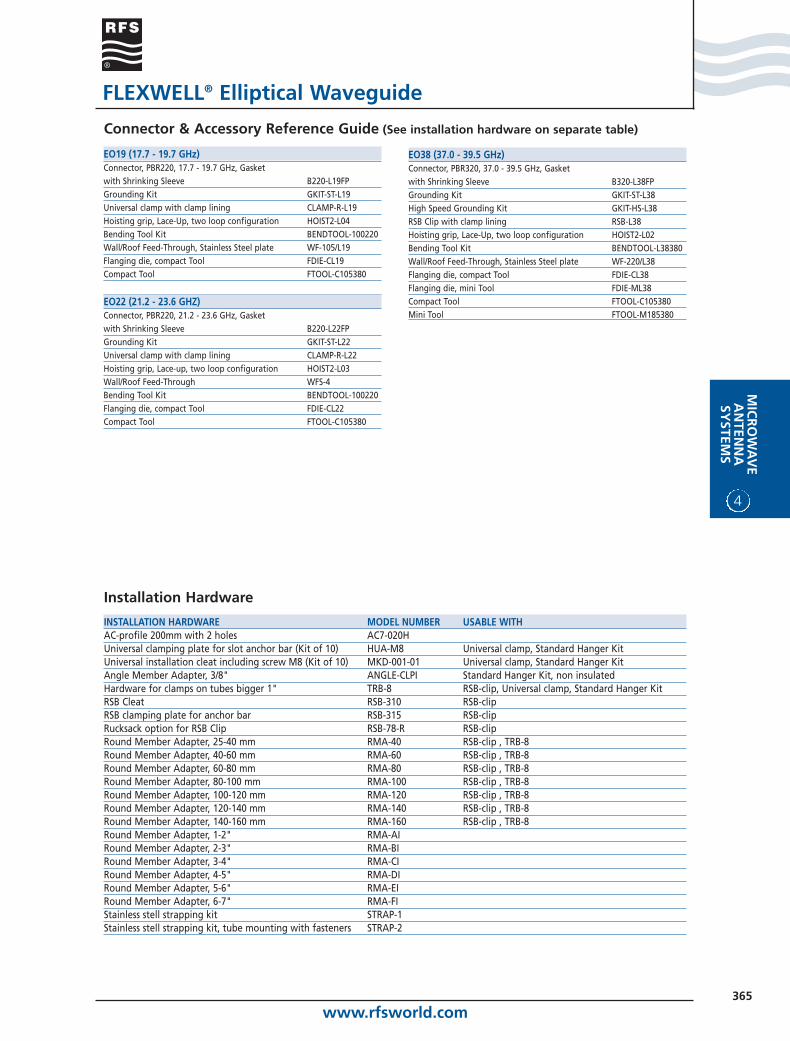
EO19 (17.7 - 19.7 GHz)Connector, PBR220, 17.7 - 19.7 GHz, Gasket with Shrinking Sleeve B220-L19FPGrounding Kit GKIT-ST-L19Universal clamp with clamp lining CLAMP-R-L19Hoisting grip, Lace-Up, two loop configuration HOIST2-L04Bending Tool Kit BENDTOOL-100220Wall/Roof Feed-Through, Stainless Steel plate WF-105/L19Flanging die, compact Tool FDIE-CL19Compact Tool FTOOL-C105380
EO22 (21.2 - 23.6 GHZ)Connector, PBR220, 21.2 - 23.6 GHz, Gasket with Shrinking Sleeve B220-L22FPGrounding Kit GKIT-ST-L22Universal clamp with clamp lining CLAMP-R-L22Hoisting grip, Lace-up, two loop configuration HOIST2-L03Wall/Roof Feed-Through WFS-4Bending Tool Kit BENDTOOL-100220Flanging die, compact Tool FDIE-CL22Compact Tool FTOOL-C105380
EO38 (37.0 - 39.5 GHz)Connector, PBR320, 37.0 - 39.5 GHz, Gasket with Shrinking Sleeve B320-L38FPGrounding Kit GKIT-ST-L38High Speed Grounding Kit GKIT-HS-L38RSB Clip with clamp lining RSB-L38Hoisting grip, Lace-Up, two loop configuration HOIST2-L02Bending Tool Kit BENDTOOL-L38380Wall/Roof Feed-Through, Stainless Steel plate WF-220/L38Flanging die, compact Tool FDIE-CL38Flanging die, mini Tool FDIE-ML38Compact Tool FTOOL-C105380Mini Tool FTOOL-M185380
INSTALLATION HARDWARE MODEL NUMBER USABLE WITHAC-profile 200mm with 2 holes AC7-020HUniversal clamping plate for slot anchor bar (Kit of 10) HUA-M8 Universal clamp, Standard Hanger KitUniversal installation cleat including screw M8 (Kit of 10) MKD-001-01 Universal clamp, Standard Hanger KitAngle Member Adapter, 3/8" ANGLE-CLPI Standard Hanger Kit, non insulatedHardware for clamps on tubes bigger 1" TRB-8 RSB-clip, Universal clamp, Standard Hanger KitRSB Cleat RSB-310 RSB-clip RSB clamping plate for anchor bar RSB-315 RSB-clip Rucksack option for RSB Clip RSB-78-R RSB-clip Round Member Adapter, 25-40 mm RMA-40 RSB-clip , TRB-8Round Member Adapter, 40-60 mm RMA-60 RSB-clip , TRB-8Round Member Adapter, 60-80 mm RMA-80 RSB-clip , TRB-8Round Member Adapter, 80-100 mm RMA-100 RSB-clip , TRB-8Round Member Adapter, 100-120 mm RMA-120 RSB-clip , TRB-8Round Member Adapter, 120-140 mm RMA-140 RSB-clip , TRB-8Round Member Adapter, 140-160 mm RMA-160 RSB-clip , TRB-8Round Member Adapter, 1-2" RMA-AIRound Member Adapter, 2-3" RMA-BIRound Member Adapter, 3-4" RMA-CIRound Member Adapter, 4-5" RMA-DIRound Member Adapter, 5-6" RMA-EIRound Member Adapter, 6-7" RMA-FIStainless stell strapping kit STRAP-1Stainless stell strapping kit, tube mounting with fasteners STRAP-2
Installation Hardware
www.rfsworld.com366
4
MIC
RO
WA
VE
AN
TEN
NA
SYST
EMS
Ordering information
Rectangular Waveguide Components
Different Rectangular waveguide components areavailable to simplify the installation especially in ashelter or to connect a radio placed near to theantenna.
The following components are offered:
• Straight sections
• 90 deg E-Bends
• 90 deg H-Bends
• 90 deg Twist sections
• Twistflex
• Pressure windows
• Shims
• Transitions
• Flange Adaptors
For flange installation hardware andblanking plates with absorbing material contact RFS.
WAVEGUIDE BENDS AND TWIST SECTIONSFreq. Range, GHz E Bend 90° H Bend 90° Twist 90° Straight 100mm (3.9 in) Flange Type3.3 - 4.2 EB040-DV HB040-DV TS040-DV SW040-DV PDR40, UDR40
EB229-CC HB229-CC TS229-CC CPR229G, CPR229G4.4 - 5.0 EB048-DV HB048-DV TS048-DV SW048-DV PDR48, UDR48
EB187-CC HB187-CC TS187-CC CPR187G, CPR187G5.725 - 7.75 EB070-DV HB070-DV TS070-DV SW070-DV PDR70, UDR70
EB137-ZU HB137-ZU TS137-ZU UG-343/U, UG-343/U7.125 - 8.5 EB084-DV HB084-DV TS084-DV SW084-DV PDR84, UDR84
EB084-BW HB084-BW TS084-BW SW084-BW PBR84, UBR84EB112-ZU HB112-ZU TS112-ZU UG-51/U, UG-52/UEB112-CC HB112-CC TS112-CC CPR112G, CPR112G
10.2 - 11.7 EB100-DV HB100-DV TS100-DV SW100-DV PDR100, UDR100EB100-BW HB100-BW TS100-BW SW100-BW PBR100, UBR100EB090-ZU HB090-ZU TS090-ZU UG-39/U, UG-40/UEB090-CC HB090-CC TS090-CC CPR090G, CPR090G
12.2 - 13.25 EB120-DV HB120-DV TS120-DV SW120-DV PDR120, UDR120EB120-BW HB120-BW TS120-BW SW120-BW PBR120, UBR120EB075-ZU HB075-ZU TS075-ZU WR75 choke, WR75 cover
14.2 - 15.35 EB140-DV HB140-DV TS140-DV SW140-DV PDR140, UDR140EB140-BW HB140-BW TS140-BW SW140-BW PBR140, UBR140
17.3 - 26.5 EB220-BW HB220-BW TS220-BW SW220-BW PBR220, UBR22027.3 - 40.0 EB320-BW HB320-BW TS320-BW SW320-BW PBR320, UBR320
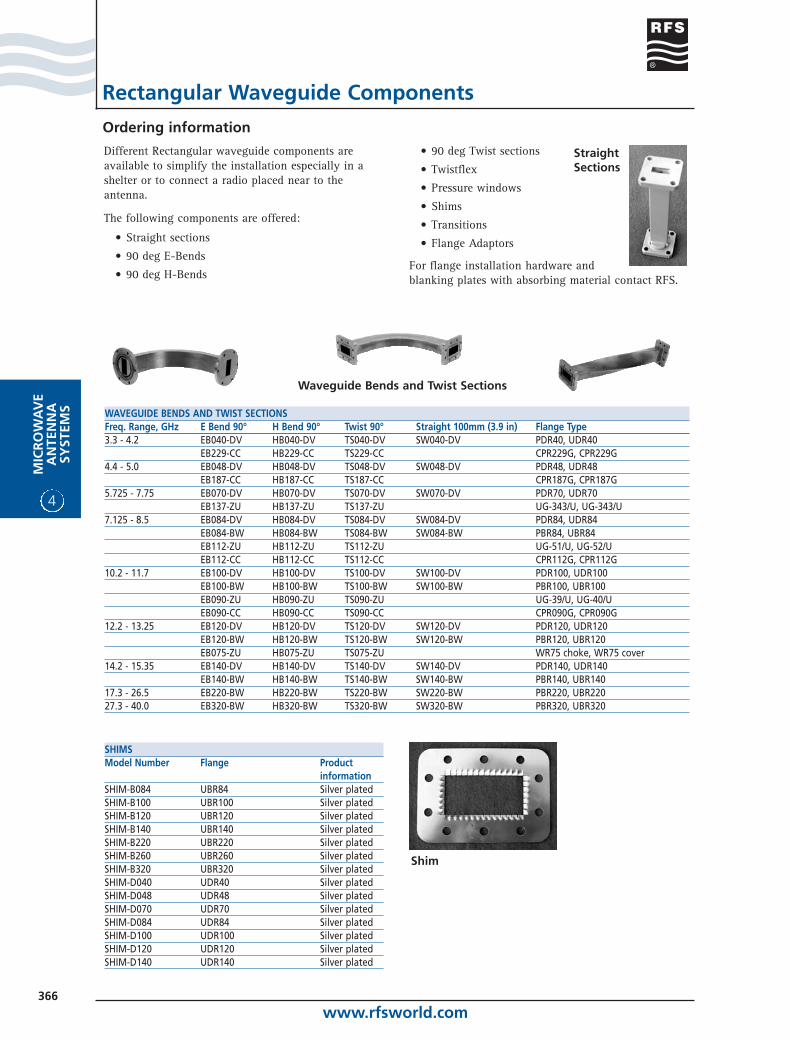
StraightSections
Waveguide Bends and Twist Sections
SHIMSModel Number Flange Product
informationSHIM-B084 UBR84 Silver platedSHIM-B100 UBR100 Silver platedSHIM-B120 UBR120 Silver platedSHIM-B140 UBR140 Silver platedSHIM-B220 UBR220 Silver platedSHIM-B260 UBR260 Silver platedSHIM-B320 UBR320 Silver platedSHIM-D040 UDR40 Silver platedSHIM-D048 UDR48 Silver platedSHIM-D070 UDR70 Silver platedSHIM-D084 UDR84 Silver platedSHIM-D100 UDR100 Silver platedSHIM-D120 UDR120 Silver platedSHIM-D140 UDR140 Silver plated
Shim
www.rfsworld.com367
MIC
RO
WA
VE
AN
TENN
ASY
STEMS
4
Ordering information
Rectangular Waveguide Components
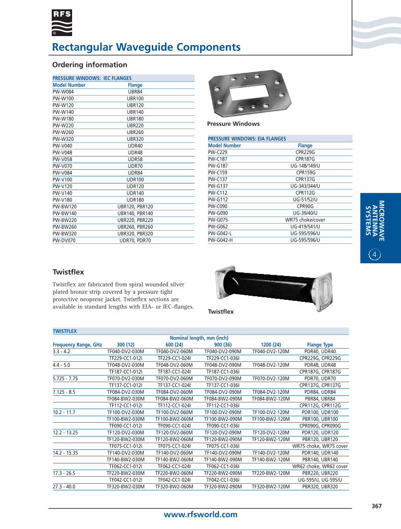
Twistflex
Twistflex are fabricated from spiral wounded silverplated bronze strip covered by a pressure tightprotective neoprene jacket. Twistflex sections areavailable in standard lengths with EIA- or IEC-flanges.
Twistflex
TWISTFLEXNominal length, mm (inch)
Frequency Range, GHz 300 (12) 600 (24) 900 (36) 1200 (24) Flange Type3.3 - 4.2 TF040-DV2-030M TF040-DV2-060M TF040-DV2-090M TF040-DV2-120M PDR40, UDR40
TF229-CC1-012I TF229-CC1-024I TF229-CC1-036I CPR229G, CPR229G4.4 - 5.0 TF048-DV2-030M TF048-DV2-060M TF048-DV2-090M TF048-DV2-120M PDR48, UDR48
TF187-CC1-012I TF187-CC1-024I TF187-CC1-036I CPR187G, CPR187G5.725 - 7.75 TF070-DV2-030M TF070-DV2-060M TF070-DV2-090M TF070-DV2-120M PDR70, UDR70
TF137-CC1-012I TF137-CC1-024I TF137-CC1-036I CPR137G, CPR137G7.125 - 8.5 TF084-DV2-030M TF084-DV2-060M TF084-DV2-090M TF084-DV2-120M PDR84, UDR84
TF084-BW2-030M TF084-BW2-060M TF084-BW2-090M TF084-BW2-120M PBR84, UBR84TF112-CC1-012I TF112-CC1-024I TF112-CC1-036I CPR112G, CPR112G
10.2 - 11.7 TF100-DV2-030M TF100-DV2-060M TF100-DV2-090M TF100-DV2-120M PDR100, UDR100TF100-BW2-030M TF100-BW2-060M TF100-BW2-090M TF100-BW2-120M PBR100, UBR100TF090-CC1-012I TF090-CC1-024I TF090-CC1-036I CPR090G, CPR090G
12.2 - 13.25 TF120-DV2-030M TF120-DV2-060M TF120-DV2-090M TF120-DV2-120M PDR120, UDR120TF120-BW2-030M TF120-BW2-060M TF120-BW2-090M TF120-BW2-120M PBR120, UBR120TF075-CC1-012I TF075-CC1-024I TF075-CC1-036I WR75 choke, WR75 cover
14.2 - 15.35 TF140-DV2-030M TF140-DV2-060M TF140-DV2-090M TF140-DV2-120M PDR140, UDR140TF140-BW2-030M TF140-BW2-060M TF140-BW2-090M TF140-BW2-120M PBR140, UBR140TF062-CC1-012I TF062-CC1-024I TF062-CC1-036I WR62 choke, WR62 cover
17.3 - 26.5 TF220-BW2-030M TF220-BW2-060M TF220-BW2-090M TF220-BW2-120M PBR220, UBR220TF042-CC1-012I TF042-CC1-024I TF042-CC1-036I UG-595/U, UG-595/U
27.3 - 40.0 TF320-BW2-030M TF320-BW2-060M TF320-BW2-090M TF320-BW2-120M PBR320, UBR320
PRESSURE WINDOWS: IEC FLANGESModel Number FlangePW-W084 UBR84PW-W100 UBR100PW-W120 UBR120PW-W140 UBR140PW-W180 UBR180PW-W220 UBR220PW-W260 UBR260PW-W320 UBR320PW-V040 UDR40PW-V048 UDR48PW-V058 UDR58PW-V070 UDR70PW-V084 UDR84PW-V100 UDR100PW-V120 UDR120PW-V140 UDR140PW-V180 UDR180PW-BW120 UBR120, PBR120PW-BW140 UBR140, PBR140PW-BW220 UBR220, PBR220PW-BW260 UBR260, PBR260PW-BW320 UBR320, PBR320PW-DV070 UDR70, PDR70
PRESSURE WINDOWS: EIA FLANGESModel Number FlangePW-C229 CPR229GPW-C187 CPR187GPW-G187 UG-148/149/UPW-C159 CPR159GPW-C137 CPR137GPW-G137 UG-343/344/UPW-C112 CPR112GPW-G112 UG-51/52/UPW-C090 CPR90GPW-G090 UG-39/40/UPW-G075 WR75 choke/coverPW-G062 UG-419/541/UPW-G042-L UG-595/596/UPW-G042-H UG-595/596/U
Pressure Windows
www.rfsworld.com368
4
MIC
RO
WA
VE
AN
TEN
NA
SYST
EMS
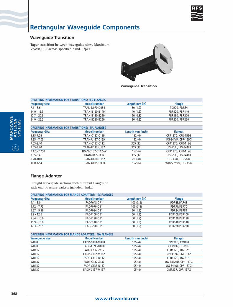
Waveguide Transition
Rectangular Waveguide Components
Taper transition between waveguide sizes. MaximumVSWR,1.05 across specified band. 1/pkg
Waveguide Transition
ORDERING INFORMATION FOR TRANSITIONS: IEC FLANGESFrequency GHz Model Number Length mm (in) Flange7.1 - 8.6 TRAN-D070-D084 50 (1.9) PDR70, PDR8414.0 - 15.5 TRAN-B120-B140 40 (1.6) PBR120, PBR14017.7 - 20.3 TRAN-B180-B220 20 (0.8) PBR180, PBR22024.0 - 26.5 TRAN-B220-B260 20 (0.8) PBR220, PBR260
ORDERING INFORMATION FOR TRANSITIONS: EIA FLANGESFrequency GHz Model Number Length mm (inch) Flanges5.85-7.05 TRAN-C137-C159 152 (6) CPR137G, CPR-159G5.85 - 7.05 TRAN-U137-C159 152 (6) UG-344/U, CPR-159G7.05-8.40 TRAN-C137-C112 305 (12) CPR137G, CPR-112G7.05-8.40 TRAN-U112-U137 305 (12) UG-51/U, UG-344/U7.125-7.750 TRAN-C137-C112-W 152 (6) CPR137G, CPR-112G7.05-8.4 TRAN-U12-U137 305 (12) UG-51/U, UG-344/U8.20-10.0 TRAN-U090-U112 203 (8) UG-39/U, UG-51/U10.0-12.4 TRAN-U075-U090 152 (6) WR75 cover, UG-39/U
ORDERING INFORMATION FOR FLANGE ADAPTERS: IEC FLANGESFrequency GHz Model Number Length mm (in) Flange4.4 - 5.0 FADP048-DP1 100 (3.8) PDR48/PAR485.72 - 7.75 FADP070-DB1 100 (3.8) PDR70/PBR706.57 - 9.99 FADP084-DB1 50 (1.9) PDR84/PBR848.2 - 12.5 FADP100-DB1 50 (1.9) PDR100/PBR1009.84 - 15.0 FADP120-DB1 50 (1.9) PDR120/PBR12011.9 - 18.0 FADP140-DB1 50 (1.9) PDR140/PBR14017.3 - 26.5 FADP220-DB1 50 (1.9) PDR220/PBR220
ORDERING INFORMATION FOR FLANGE ADAPTERS: EIA FLANGESWaveguide size Model Number Length mm (inch) FlangesWR90 FADP-C090-M090 105 (4) CPR90G, CMR90WR90 FADP-C090-U090 105 (4) CPR90G, UG39/UWR112 FADP-C112-Z112 105 (4) CPR112G, UG-52/UWR112 FADP-C112-M112 105 (4) CPR112G, CMR-112WR112 FADP-C112-U112 105 (4) CPR112G, UG-51/UWR137 FADP-C137-Z137 105 (4) UG-343A/U, CPR-137GWR137 FADP-C137-U137 105 (4) UG-344/U, CPR-137GWR137 FADP-C137-M137 105 (4) CMR137, CPR-137G
Flange Adapter
Straight waveguide sections with different flanges oneach end. Pressure gaskets included. 1/pkg
www.rfsworld.com369
MIC
RO
WA
VE
AN
TENN
ASY
STEMS
4
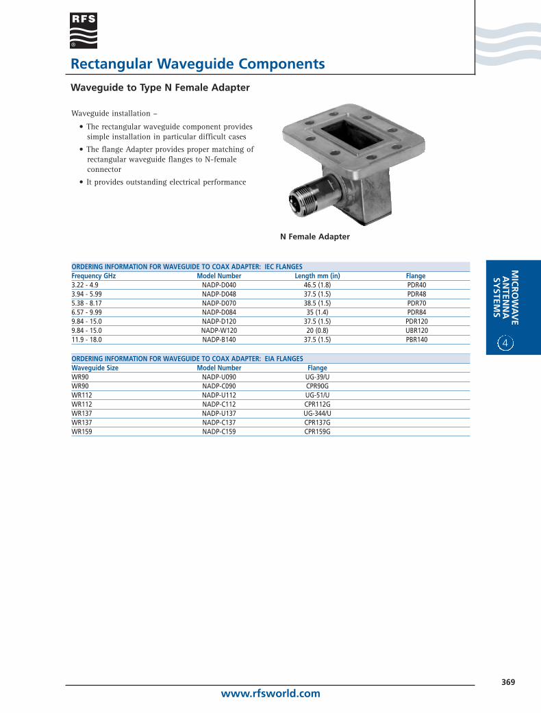
Waveguide to Type N Female Adapter
Rectangular Waveguide Components
ORDERING INFORMATION FOR WAVEGUIDE TO COAX ADAPTER: IEC FLANGESFrequency GHz Model Number Length mm (in) Flange3.22 - 4.9 NADP-D040 46.5 (1.8) PDR403.94 - 5.99 NADP-D048 37.5 (1.5) PDR485.38 - 8.17 NADP-D070 38.5 (1.5) PDR706.57 - 9.99 NADP-D084 35 (1.4) PDR849.84 - 15.0 NADP-D120 37.5 (1.5) PDR1209.84 - 15.0 NADP-W120 20 (0.8) UBR12011.9 - 18.0 NADP-B140 37.5 (1.5) PBR140
ORDERING INFORMATION FOR WAVEGUIDE TO COAX ADAPTER: EIA FLANGESWaveguide Size Model Number FlangeWR90 NADP-U090 UG-39/UWR90 NADP-C090 CPR90GWR112 NADP-U112 UG-51/UWR112 NADP-C112 CPR112GWR137 NADP-U137 UG-344/UWR137 NADP-C137 CPR137GWR159 NADP-C159 CPR159G
Waveguide installation –
• The rectangular waveguide component providessimple installation in particular difficult cases
• The flange Adapter provides proper matching ofrectangular waveguide flanges to N-femaleconnector
• It provides outstanding electrical performance
N Female Adapter