Fixed Wing Design Tool
77
Profile Notes/Sources: 0 Source: "2006-2007 AI 1 2 3 4 5 6 7 8 9 10 20 min. Combat @ Corner Speed/SL Max Power Climb to Opt. Alt. Cruise Back 800 nm @ Optimum Speed/Alt Descend to SL @ Idle Thrust Setting 20 min Loiter @ Endurance Speel/SL Landing with 30 min Reserve Fuel @ SL Mission Profile Warm-up Taxi Max Perforamnce Take-Off @ SL Max Power Climb to Opt. Alt. Cruise out 800 nm @ Optimum Speed/Alt Loiter for 20 min. @ 5,000ft
-
Upload
mani-rathinam-rajamani -
Category
Documents
-
view
36 -
download
1
description
Filename: FIXED_WING_DESIGN_TOOL.xls
Transcript of Fixed Wing Design Tool

Profile Notes/Sources:
0 Source: "2006-2007 AIAA Graduate Team Aircraft Design Competition - Modifiied RFP"
1
2
3
4
5
6
7
8
9
10
20 min. Combat @ Corner Speed/SL
Max Power Climb to Opt. Alt.
Cruise Back 800 nm @ Optimum Speed/Alt
Descend to SL @ Idle Thrust Setting
20 min Loiter @ Endurance Speel/SL
Landing with 30 min Reserve Fuel @ SL
Mission Profile
Warm-up Taxi
Max Perforamnce Take-Off @ SL
Max Power Climb to Opt. Alt.
Cruise out 800 nm @ Optimum Speed/Alt
Loiter for 20 min. @ 5,000ft

Source: "2006-2007 AIAA Graduate Team Aircraft Design Competition - Modifiied RFP"

Step 1 Payload Calculations, WPL Notes/Sources:
3,240 lbs Source: "2006-2007 AIAA Graduate Team Aircraft Design Competition - Modifiied RFP"
5,000 lbs
12,000 lbs
Total WPL 12,000 lbs Enter Payload based on above values, and Desired Mission (for baseline misson, assume worst case external stores)
Crew Weight
250 lbs Source: "2006-2007 AIAA Graduate Team Aircraft Design Competition - Modifiied RFP"
Total WCREW 250 lbs
Step 2 Weight Take Off Guess Based on Historical Data, WTO_GUESS
W_PL W_TO V_MAX Range Source: Taylor, J.W.R, Jane's All The World Aircraft Published Annually by: Jane's Publishing Company, (Issues used: 1945/45, 1968/84)
(lbs) (lbs) (kts) (nm) Source: Roskam, "Airplane Design, Part I: Preliminary Sizing of Airplanes", 1985, pg 60
15,000 50,000 450 540
17,000 60,400 689 1,700
16,000 58,400 600 750
Average: 16,000 56,267 580 997 Some initial guess for TOGW, will only be used for reference, program automatically calculates TOGW based on historical data
WTO_GUESS 59,488 lbs Later this will be iterated to find weight empty
Step 3 Mission Fuel Weight Fractions, WF Source: Roskam, "Airplane Design, Part I: Preliminary Sizing of Airplanes", 1985, pg 12
Climb 1
Range Credit 24.5 nm Assume 10,000 ft/min climb (from RFP) and 350 knot ground speed during climb (from Roskam page 62); therefore, Rclimb = Alt./(10K/min)*350knots
Cruise 1
Rcr, Cruise Range 775.5 nm 800 nm specified in RFP - climb 1 range
Altitude 42,000 ft
Temperature @ Alt, T -90.6o F
Delta 0.1668
Theta 0.7116
GD GAU-8 30-mm Cannon is part of weight empty
External Stores is deemed the limiting case
Tornado F.Mk2
Aircraft Type
Mission Analysis
Ammunition Weight (1.62 lbs x 2000 rounds)
F.R. A10A
Grumman A6
Internal Stores Max
External Stores Max
Crew (1x250lbs)

Seg. Description Altitude Temp. Density Velocity Range
(ft) (°F) slug/ft^3 knots nm
0 0 59.0 2.377E-03 0.0 -
1 Warm-up Taxi 0 59.0 2.377E-03 0.0 -
2 Max Perforamnce Take-Off @ SL 0 59.0 2.377E-03 TBD -
3 Max Power Climb to Opt. Alt. 42,000 -90.6 5.571E-04 350.0 25
4 Cruise out 800 nm @ Optimum Speed/Alt 42,000 -90.6 5.571E-04 459.0 800
5 Loiter for 20 min. @ 5,000ft 5,000 41.2 2.048E-03 226.6 800
6 20 min. Combat @ Corner Speed/SL 0 59.0 2.377E-03 275.0 800
7 Max Power Climb to Opt. Alt. 42,000 -90.6 5.571E-04 350.0 825
8 Cruise Back 800 nm @ Optimum Speed/Alt 42,000 -90.6 5.571E-04 459.0 1,600
9 Descend to SL @ Idle Thrust Setting 0 0.0 2.377E-03 459.0 1,600
10 20 min Loiter @ Endurance Speel/SL 0 0.0 2.377E-03 187.5 1,600
11 Landing with 30 min Reserve Fuel @ SL 0 0.0 2.377E-03 0.0 1,600
Mission Summary (Baseline Mission)

q CL CD L/D Wn-1/Wn Fuel Burn Fuel Weight Beta
psf (lbs) (lbs) (lbs)
0 0.0000 0.0172 0.00 1.000 - - 59,488 1.000
0 0.0000 0.0172 0.00 0.990 595 595 58,894 0.990
0 TBD TBD 0.990 1,184 589 58,305 0.980
- - - - 0.960 3,516 2,332 55,972 0.941
167 0.3940 0.0282 13.97 0.930 7,434 3,918 52,054 0.875
150 0.4088 0.0291 14.07 0.986 8,161 727 51,327 0.863
256 1.1794 0.1160 10.17 0.974 9,477 1,315 50,012 0.841
- - - - 0.960 11,477 2,000 48,011 0.807
167 0.3379 0.0253 13.36 0.927 14,985 3,508 44,504 0.748
167 0.3379 0.0253 13.36 1.000 14,985 - 44,504 0.748
119 0.4400 0.0309 14.23 0.986 15,600 615 43,889 0.738
0 0.0000 0.0172 0.00 0.979 16,516 916 42,973 0.722

Input Source: This section describes where the initial input values are referenced from
Lapse Rate α 0.243478 α Lapse Rate Based on High Bypass Ratio Turbofan Engine, Source: Hernando Jimenez - "An Energy Based Approach to Aircraft Constraint Analysis - Part 2), ASDL GA Tech, AE6343, Fall 2006
Fuel/Payload β 0.9801 β At Cruising Altitude
Load Factor n 1 n Level Flight n=1
Gravity g 32.2 ft/s2 g Earth
Excrescence Drag R 0 slug/ft3 R Gear retracted for level flight
Freesteam Velocity Velocity 774.7048 ft/s Velocity Optimum Cruise first guess assumed to be 459 knots, Fighter Example Problem, Source: Roskam, "Airplane Design, Part I: Preliminary Sizing of Airplanes", 1985, pg 62
Dynamic Pressure q 167.18 psf q Calculated from Velocity and Ambient Conditions
Min Drag CD0 0.017179 CD0Includes External Stores Source: Roskam, "Airplane Design, Part I: Preliminary Sizing of Airplanes", 1985, pg 118-122, 156, 166 for Fighters
Drag Polar Coefficient K1 0.07 K1 Source: Roskam, "Airplane Design, Part I: Preliminary Sizing of Airplanes", 1985, pg 156
Drag Polar Coefficient K2 0 K2Typically Zero, Source: Roskam, "Airplane Design, Part I: Preliminary Sizing of Airplanes", 1985, pg 156
Vertical Velocity dh/dt 0 ft/s dh/dt zero, no change in altitude
Vertical Acceleration dV/dt 0 ft/s2 dV/dt zero, no change in vertical acceleration
Additional Inputs
Altitude 42,000 ft Altitude Cruising Alt.
Temperature @ Alt, T -90.6o F Temperature @ Alt, TBased on Standard Day Atmosphere
Delta 0.1668 Delta
Theta 0.7116 Theta
Sigma 0.2344 Sigma
Density 5.571E-04 slugs/ft3
Density
Weight 58,305 lbs Weight
VCRUISE 459.00 kts VCRUISEOptimum Cruise first guess assumed to be 459 knots, Fighter Example Problem, Source: Roskam, "Airplane Design, Part I: Preliminary Sizing of Airplanes", 1985, pg 62
M 0.823 M Wings are swept to reduce compressibility in transonic regime
Input Source: This section describes where the initial input values are referenced from
Lapse Rate α 0.23888 α Lapse Rate Based on High Bypass Ratio Turbofan Engine, Source: Hernando Jimenez - "An Energy Based Approach to Aircraft Constraint Analysis - Part 2), ASDL GA Tech, AE6343, Fall 2006
Fuel/Payload β 0.9801 β At Cruising Altitude
Load Factor n 1 n Level Flight n=1
Gravity g 32.2 ft/s2 g Earth
Excrescence Drag R 0 slug/ft3 R Gear retracted for level flight
Freesteam Velocity Velocity 928.2955 ft/s Velocity Specified in RFP - "2006-2007 AIAA Graduate Team Aircraft Design Competition - Modified", AE 6343, Project 1, Fall 2007
Dynamic Pressure q 240.04 psf q Calculated from Velocity and Ambient Conditions
Min Drag CD0 0.019679 CD0Drag Include Compressibility for High Mach Number, and External Stores Source: Roskam, "Airplane Design, Part I: Preliminary Sizing of Airplanes", 1985, pg 118-122, 156, 166 for Fighters
Drag Polar Coefficient K1 0.07 K1 Source: Roskam, "Airplane Design, Part I: Preliminary Sizing of Airplanes", 1985, pg 156
Drag Polar Coefficient K2 0 K2Typically Zero, Source: Roskam, "Airplane Design, Part I: Preliminary Sizing of Airplanes", 1985, pg 156
Vertical Velocity dh/dt 0 ft/s dh/dt zero, no change in altitude
Vertical Acceleration dV/dt 0 ft/s2 dV/dt zero, no change in vertical acceleration
Additional Inputs
Altitude 42,000 ft Altitude Cruising Alt.
Temperature @ Alt, T -90.6o F Temperature @ Alt, TBased on Standard Day Atmosphere
Delta 0.1668 Delta
Theta 0.7116 Theta
Sigma 0.2344 Sigma
Density 5.571E-04 slugs/ft3
Density
Constraint Analysis as a Function of T/W and T/S
Max Cruise Speed, 550 kts (Ps=0)
Constant Altitude/Speed Cruise (Ps=0)

Weight 58,305 lbs Weight
VCRUISE_MAX 550.00 kts VCRUISE_MAXVelocity in knots for my Reference
M 0.986 M Due to the High Mach number there will be additional drag due to Compressibility
Input Source: This section describes where the initial input values are referenced from
Lapse Rate α 0.688611 α Lapse Rate Based on High Bypass Ratio Turbofan Engine, Source: Hernando Jimenez - "An Energy Based Approach to Aircraft Constraint Analysis - Part 2), ASDL GA Tech, AE6343, Fall 2006
Fuel/Payload β 1 β Specified by RFP to be Max TOGW
Load Factor n 3.180281 n Sustained Turn will require a certain g value based on the turn rate, this can be calculated from source: Raymer, "Aircraft Design, A Conceptual Approach, 3rd Edition", 1999, pg 106
Gravity g 32.2 ft/s2 g Earth
Excrescence Drag R 0 slug/ft3 R Gear retracted
Freesteam Velocity Velocity 464.1478 ft/s Velocity 275 knots min, provided by RFP
Dynamic Pressure q 256.04 psf q Calculated from Velocity and Ambient Conditions
Min Drag CD0 0.017179 CD0Includes External Stores Source: Roskam, "Airplane Design, Part I: Preliminary Sizing of Airplanes", 1985, pg 118-122, 156, 166 for Fighters
Drag Polar Coefficient K1 0.07 K1 Source: Roskam, "Airplane Design, Part I: Preliminary Sizing of Airplanes", 1985, pg 156
Drag Polar Coefficient K2 0 K2Typically Zero, Source: Roskam, "Airplane Design, Part I: Preliminary Sizing of Airplanes", 1985, pg 156
Vertical Velocity dh/dt 0 ft/s dh/dt zero, no change in altitude
Vertical Acceleration dV/dt 0 ft/s2 dV/dt zero, no change in vertical acceleration
Additional Inputs
Altitude 0 ft Altitude
Temperature @ Alt, T 59.0o F Temperature @ Alt, TBased on Standard Day Atmosphere
Delta 1.0000 Delta
Theta 1.0000 Theta
Sigma 1.0000 Sigma
Density 2.377E-03 slugs/ft3
Density
Weight 59,488 lbs Weight
VCRUISE 275.00 kts VCRUISE 275 knots min, provided by RFP
M 0.416 M
Input Source: This section describes where the initial input values are referenced from
Lapse Rate α 0.225354 α Lapse Rate Based on High Bypass Ratio Turbofan Engine, Source: Hernando Jimenez - "An Energy Based Approach to Aircraft Constraint Analysis - Part 2), ASDL GA Tech, AE6343, Fall 2006
Fuel/Payload β 1 β Specified by RFP to be Max TOGW
Load Factor n 1 n Level Flight n=1
Gravity g 32.2 ft/s2 g Earth
Excrescence Drag R 0 slug/ft3 R Gear retracted
Freesteam Velocity Velocity 774.7048 ft/s Velocity Cruise Velocity
Dynamic Pressure q 147.49 psf q Calculated from Velocity and Ambient Conditions
Min Drag CD0 0.017179 CD0Includes External Stores Source: Roskam, "Airplane Design, Part I: Preliminary Sizing of Airplanes", 1985, pg 118-122, 156, 166 for Fighters
Drag Polar Coefficient K1 0.07 K1 Source: Roskam, "Airplane Design, Part I: Preliminary Sizing of Airplanes", 1985, pg 156
Drag Polar Coefficient K2 0 K2Typically Zero, Source: Roskam, "Airplane Design, Part I: Preliminary Sizing of Airplanes", 1985, pg 156
Vertical Velocity dh/dt 1.667 ft/s dh/dt Specified 100 ft/min capability at 45,000 ft (Service Ceiling) to allow for maneuver margin. Requirement from RFP
Vertical Acceleration dV/dt 0 ft/s2 dV/dt zero, no change in vertical acceleration
Additional Inputs
Altitude 45,000 ft Altitude Max Altitude
Temperature @ Alt, T -101.2o F Temperature @ Alt, TBased on Standard Day Atmosphere
Delta 0.1429 Delta
Theta 0.6910 Theta
Level Combat Corner Speed 275kts (Ps=0)
Service Ceiling, 45,000 ft. (100 ft/min)

Sigma 0.2068 Sigma
Density 4.915E-04 slugs/ft3
Density
Weight 59,488 lbs Weight
VCRUISE 459.00 kts VCRUISE
M 0.835 M
Input Source: This section describes where the initial input values are referenced from
Lapse Rate α 0.856454 α Lapse Rate Based on High Bypass Ratio Turbofan Engine, Source: Hernando Jimenez - "An Energy Based Approach to Aircraft Constraint Analysis - Part 2), ASDL GA Tech, AE6343, Fall 2006
Fuel/Payload β 1 β Specified by RFP to be Max TOGW
Load Factor n 1 n Level Flight n=1
Gravity g 32.2 ft/s2 g Earth
Excrescence Drag R 0 slug/ft3 R Gear retracted
Freesteam Velocity Velocity 168.781 ft/s Velocity Stall Speed must be no greater then 100 knots @ SL Max TOGW, from RFP
Dynamic Pressure q 33.86 psf q Calculated from Velocity and Ambient Conditions
Min Drag CD0 0.037179 CD0Includes Flaps Down, External Stores Source: Roskam, "Airplane Design, Part I: Preliminary Sizing of Airplanes", 1985, pg 118-122, 156, 166 for Fighters
Drag Polar Coefficient K1 0.07 K1 Source: Roskam, "Airplane Design, Part I: Preliminary Sizing of Airplanes", 1985, pg 156
Drag Polar Coefficient K2 0 K2Typically Zero, Source: Roskam, "Airplane Design, Part I: Preliminary Sizing of Airplanes", 1985, pg 156
Vertical Velocity dh/dt 0 ft/s dh/dt zero, no change in altitude
Vertical Acceleration dV/dt 0 ft/s2 dV/dt zero, no change in vertical acceleration
Additional Inputs
Altitude 0 ft Altitude
Temperature @ Alt, T 59.0o F Temperature @ Alt, TBased on Standard Day Atmosphere
Delta 1.0000 Delta
Theta 1.0000 Theta
Sigma 1.0000 Sigma
Density 2.377E-03 slugs/ft3
Density
Weight 59,488 lbs Weight
VSTALL 100.00 kts VSTALL Stall Speed must be no greater then 100 knots @ SL Max TOGW, from RFP
M 0.151 M
Input Source: This section describes where the initial input values are referenced from
Lapse Rate α 0.643503 α Lapse Rate Based on High Bypass Ratio Turbofan Engine, Source: Hernando Jimenez - "An Energy Based Approach to Aircraft Constraint Analysis - Part 2), ASDL GA Tech, AE6343, Fall 2006
Fuel/Payload β 1 β Specified by RFP to be Max TOGW
Load Factor n 1 n Level Flight n=1
Gravity g 32.2 ft/s2 g Earth
Excrescence Drag R 0 slug/ft3 R Gear retracted
Freesteam Velocity Velocity 590.7335 ft/s Velocity Assume 10,000 ft/min climb (from RFP) and 350 knot ground speed during climb (from Roskam page 62); therefore, Rclimb = Alt./(10K/min)*350knots
Dynamic Pressure q 414.74 psf q Calculated from Velocity and Ambient Conditions
Min Drag CD0 0.017179 CD0Includes External Stores Source: Roskam, "Airplane Design, Part I: Preliminary Sizing of Airplanes", 1985, pg 118-122, 156, 166 for Fighters
Drag Polar Coefficient K1 0.07 K1 Source: Roskam, "Airplane Design, Part I: Preliminary Sizing of Airplanes", 1985, pg 156
Drag Polar Coefficient K2 0 K2Typically Zero, Source: Roskam, "Airplane Design, Part I: Preliminary Sizing of Airplanes", 1985, pg 156
Vertical Velocity dh/dt 166.67 ft/s dh/dt Specified 10,000 ft/min capability at SL/Max TOGW, Requirement from RFP
Vertical Acceleration dV/dt 0 ft/s2 dV/dt zero, no change in vertical acceleration
Additional Inputs
Altitude 0 ft Altitude Max Altitude
Temperature @ Alt, T 59.0o F Temperature @ Alt, TBased on Standard Day Atmosphere
Delta 1.0000 Delta
Stall Speed, 100 knots
Rate of Climb,10,000 ft/min

Theta 1.0000 Theta
Sigma 1.0000 Sigma
Density 2.377E-03 slugs/ft3
Density
Weight 59,488 lbs Weight
VCLIMB 350.00 kts VCLIMBAssume 10,000 ft/min climb (from RFP) and 350 knot ground speed during climb (from Roskam page 62); therefore, Rclimb = Alt./(10K/min)*350knots
M 0.529 M
Input Source: This section describes where the initial input values are referenced from
Lapse Rate α 0.449458 α Lapse Rate Based on High Bypass Ratio Turbofan Engine, Source: Hernando Jimenez - "An Energy Based Approach to Aircraft Constraint Analysis - Part 2), ASDL GA Tech, AE6343, Fall 2006
Fuel/Payload β 0.75 β Specified by RFP to be 75% of Max TOGW
Load Factor n 5.137207 n Sustained Turn will require a certain g value based on the turn rate, this can be calculated from source: Raymer, "Aircraft Design, A Conceptual Approach, 3rd Edition", 1999, pg 106
Gravity g 32.2 ft/s2 g Earth
Excrescence Drag R 0 slug/ft3 R Gear retracted
Freesteam Velocity Velocity 774.7048 ft/s Velocity 459 cruise speed, but max speed is 550
Dynamic Pressure q 448.76 psf q Calculated from Velocity and Ambient Conditions
Min Drag CD0 0.017179 CD0Includes External Stores Source: Roskam, "Airplane Design, Part I: Preliminary Sizing of Airplanes", 1985, pg 118-122, 156, 166 for Fighters
Drag Polar Coefficient K1 0.07 K1 Source: Roskam, "Airplane Design, Part I: Preliminary Sizing of Airplanes", 1985, pg 156
Drag Polar Coefficient K2 0 K2Typically Zero, Source: Roskam, "Airplane Design, Part I: Preliminary Sizing of Airplanes", 1985, pg 156
Vertical Velocity dh/dt 0 ft/s dh/dt zero, no change in altitude
Vertical Acceleration dV/dt 0 ft/s2 dV/dt zero, no change in vertical acceleration
Additional Inputs
Altitude 15,000 ft Altitude Specified by RFT
Temperature @ Alt, T 5.6o F Temperature @ Alt, TBased on Standard Day Atmosphere
Delta 0.5643 Delta
Theta 0.8970 Theta
Sigma 0.6292 Sigma
Density 1.495E-03 slugs/ft3
Density
Weight 44,616 lbs Weight
VCRUISE 459.00 kts VCRUISE 459 cruise speed, but max speed is 550
M 0.733 M
Input Source: This section describes where the initial input values are referenced from
Lapse Rate α 0.852729 α Lapse Rate Based on High Bypass Ratio Turbofan Engine, Source: Hernando Jimenez - "An Energy Based Approach to Aircraft Constraint Analysis - Part 2), ASDL GA Tech, AE6343, Fall 2006
Fuel/Payload β 1 β Take off is max Take off wieght Beta = 1
Load Factor n 1 n
Gravity g 32.2 ft/s2 g Earth
Excrescence Drag R 0.01 slug/ft3 R Gear Down, 10 sq.ft for landing gear
Freesteam Velocity Velocity 173.8444 ft/s Velocity Speed for Take off
Dynamic Pressure q 35.92 psf q Calculated from Velocity and Ambient Conditions
Min Drag CD0 0.037179 CD0Must have Flaps, Includes External Stores Source: Roskam, "Airplane Design, Part I: Preliminary Sizing of Airplanes", 1985, pg 118-122, 156, 166 for Fighters
Drag Polar Coefficient K1 0.07 K1 Source: Roskam, "Airplane Design, Part I: Preliminary Sizing of Airplanes", 1985, pg 156
Drag Polar Coefficient K2 0 K2Typically Zero, Source: Roskam, "Airplane Design, Part I: Preliminary Sizing of Airplanes", 1985, pg 156
Vertical Velocity dh/dt 0 ft/s dh/dt zero, no change in altitude
Vertical Acceleration dV/dt 0 ft/s2 dV/dt zero, no change in vertical acceleration
Additional Inputs
Altitude 0 ft Altitude Specified by RFT
Temperature @ Alt, T 59.0o F Temperature @ Alt, TBased on Standard Day Atmosphere
Takeoff Ground Roll
Sustained Turn Rate 12deg./s

Delta 1.0000 Delta
Theta 1.0000 Theta
Sigma 1.0000 Sigma
Density 2.377E-03 slugs/ft3
Density
Weight 59,488 lbs Weight
CLMAX 1.900 CLMAX Weight and Speed at Take off to make CLMAX=1.9, Source: Roskam, "Airplane Design, Part I: Preliminary Sizing of Airplanes", 1985, pg 185
VTO 103.00 kts VTO Speed for Take off
M 0.156 M
μg 0.025 μgHot Runway Coefficient of Friction Source: Roskam, "Airplane Design, Part I: Preliminary Sizing of Airplanes", 1985, pg 185
Distance 2000 ft s_takeoff Required in RFP
kto 1.2 K for take off, Source: Hernando Jimenez - "An Energy Based Approach to Aircraft Constraint Analysis - Part 2), ASDL GA Tech, AE6343, Fall 2006
tr 3 s 3 seconds for rotation, typical for most fighters, Source: Hernando Jimenez - "An Energy Based Approach to Aircraft Constraint Analysis - Part 2), ASDL GA Tech, AE6343, Fall 2006
Input Source: This section describes where the initial input values are referenced from
Lapse Rate α 0.852729 α Lapse Rate Based on High Bypass Ratio Turbofan Engine, Source: Hernando Jimenez - "An Energy Based Approach to Aircraft Constraint Analysis - Part 2), ASDL GA Tech, AE6343, Fall 2006
Fuel/Payload β 0.737769 β Landing distance is based on the weight at the end of the mission, therefore, the beta chosen reflects the end of the mission before the reserve loiter
Load Factor n 1 n Sustained Turn will require a certain g value based on the turn rate, this can be calculated from source: Raymer, "Aircraft Design, A Conceptual Approach, 3rd Edition", 1999, pg 106
Gravity g 32.2 ft/s2 g Earth
Excrescence Drag R 0.01 slug/ft3 R Gear Down, 10 sq.ft for landing gear
Freesteam Velocity Velocity 173.8444 ft/s Velocity Speed for Take off
Dynamic Pressure q 35.92 psf q Calculated from Velocity and Ambient Conditions
Min Drag CD0 0.037179 CD0Must have Flaps, Includes External Stores Source: Roskam, "Airplane Design, Part I: Preliminary Sizing of Airplanes", 1985, pg 118-122, 156, 166 for Fighters
Drag Polar Coefficient K1 0.07 K1 Source: Roskam, "Airplane Design, Part I: Preliminary Sizing of Airplanes", 1985, pg 156
Drag Polar Coefficient K2 0 K2Typically Zero, Source: Roskam, "Airplane Design, Part I: Preliminary Sizing of Airplanes", 1985, pg 156
Vertical Velocity dh/dt 0 ft/s dh/dt zero, no change in altitude
Vertical Acceleration dV/dt 0 ft/s2 dV/dt zero, no change in vertical acceleration
Additional Inputs
Altitude 0 ft Altitude Specified by RFT
Temperature @ Alt, T 59.0o F Temperature @ Alt, TBased on Standard Day Atmosphere
Delta 1.0000 Delta
Theta 1.0000 Theta
Sigma 1.0000 Sigma
Density 2.377E-03 slugs/ft3
Density
Weight 43,889 lbs Weight
CLMAX 1.900 CLMAX Weight and Speed at Take off to make CLMAX=1.9, Source: Roskam, "Airplane Design, Part I: Preliminary Sizing of Airplanes", 1985, pg 185
VL 103.00 kts VTO Speed for Take off
M 0.156 M
μg 0.025 μgHot Runway Coefficient of Friction Source: Roskam, "Airplane Design, Part I: Preliminary Sizing of Airplanes", 1985, pg 185
SFL 2000 ft s_landing Required in RFP
kto 1.2 K for take off, Source: Hernando Jimenez - "An Energy Based Approach to Aircraft Constraint Analysis - Part 2), ASDL GA Tech, AE6343, Fall 2006
tr 3 s 3 seconds for rotation, typical for most fighters, Source: Hernando Jimenez - "An Energy Based Approach to Aircraft Constraint Analysis - Part 2), ASDL GA Tech, AE6343, Fall 2006
SL 3800 ft Source: Roskam, "Airplane Design, Part I: Preliminary Sizing of Airplanes", 1985, pg 187
SFL 6333.333
VA 158 kts^2
VSL 131.4464 kts
VSL 221.8566 ft/s
Landing Distance

Input Source: This section describes where the initial input values are referenced from
Takeoff Ground Roll HOT DAY

Lapse Rate α 0.811621 α Lapse Rate Based on High Bypass Ratio Turbofan Engine, Source: Hernando Jimenez - "An Energy Based Approach to Aircraft Constraint Analysis - Part 2), ASDL GA Tech, AE6343, Fall 2006
Fuel/Payload β 1 β Take off is max Take off wieght Beta = 1
Load Factor n 1 n
Gravity g 32.2 ft/s2 g Earth
Excrescence Drag R 0.01 slug/ft3 R Gear Down, 10 sq.ft for landing gear
Freesteam Velocity Velocity 173.8444 ft/s Velocity Speed for Take off
Dynamic Pressure q 32.70 psf q Calculated from Velocity and Ambient Conditions
Min Drag CD0 0.037179 CD0Must have Flaps, Includes External Stores Source: Roskam, "Airplane Design, Part I: Preliminary Sizing of Airplanes", 1985, pg 118-122, 156, 166 for Fighters
Drag Polar Coefficient K1 0.07 K1 Source: Roskam, "Airplane Design, Part I: Preliminary Sizing of Airplanes", 1985, pg 156
Drag Polar Coefficient K2 0 K2Typically Zero, Source: Roskam, "Airplane Design, Part I: Preliminary Sizing of Airplanes", 1985, pg 156
Vertical Velocity dh/dt 0 ft/s dh/dt zero, no change in altitude
Vertical Acceleration dV/dt 0 ft/s2 dV/dt zero, no change in vertical acceleration
Additional Inputs
Altitude 0 ft Altitude Specified by RFT
Temperature @ Alt, T 110.0o F Temperature @ Alt, TAfghanistan at sea level can reach tempratures of 110 °F
Delta 1.0000 Delta
Theta 1.0983 Theta
Sigma 0.9105 Sigma
Density 2.164E-03 slugs/ft3
Density
Weight 59,488 lbs Weight
CLMAX 1.900 CLMAX Weight and Speed at Take off to make CLMAX=1.9, Source: Roskam, "Airplane Design, Part I: Preliminary Sizing of Airplanes", 1985, pg 185
VTO 103.00 kts VTO Speed for Take off
M 0.149 M
μg 0.025 μgHot Runway Coefficient of Friction Source: Roskam, "Airplane Design, Part I: Preliminary Sizing of Airplanes", 1985, pg 185
Distance 2000 ft s_takeoff Required in RFP
kto 1.2 K for take off, Source: Hernando Jimenez - "An Energy Based Approach to Aircraft Constraint Analysis - Part 2), ASDL GA Tech, AE6343, Fall 2006
tr 3 s 3 seconds for rotation, typical for most fighters, Source: Hernando Jimenez - "An Energy Based Approach to Aircraft Constraint Analysis - Part 2), ASDL GA Tech, AE6343, Fall 2006

Source: This section describes where the initial input values are referenced from
Lapse Rate Based on High Bypass Ratio Turbofan Engine, Source: Hernando Jimenez - "An Energy Based Approach to Aircraft Constraint Analysis - Part 2), ASDL GA Tech, AE6343, Fall 2006
At Cruising Altitude
Level Flight n=1
Gear retracted for level flight
Optimum Cruise first guess assumed to be 459 knots, Fighter Example Problem, Source: Roskam, "Airplane Design, Part I: Preliminary Sizing of Airplanes", 1985, pg 62
Calculated from Velocity and Ambient Conditions
Includes External Stores Source: Roskam, "Airplane Design, Part I: Preliminary Sizing of Airplanes", 1985, pg 118-122, 156, 166 for Fighters
Source: Roskam, "Airplane Design, Part I: Preliminary Sizing of Airplanes", 1985, pg 156
Typically Zero, Source: Roskam, "Airplane Design, Part I: Preliminary Sizing of Airplanes", 1985, pg 156
zero, no change in altitude
zero, no change in vertical acceleration
Cruising Alt.
Based on Standard Day Atmosphere
Optimum Cruise first guess assumed to be 459 knots, Fighter Example Problem, Source: Roskam, "Airplane Design, Part I: Preliminary Sizing of Airplanes", 1985, pg 62
Wings are swept to reduce compressibility in transonic regime
Source: This section describes where the initial input values are referenced from
Lapse Rate Based on High Bypass Ratio Turbofan Engine, Source: Hernando Jimenez - "An Energy Based Approach to Aircraft Constraint Analysis - Part 2), ASDL GA Tech, AE6343, Fall 2006
At Cruising Altitude
Level Flight n=1
Gear retracted for level flight
Specified in RFP - "2006-2007 AIAA Graduate Team Aircraft Design Competition - Modified", AE 6343, Project 1, Fall 2007
Calculated from Velocity and Ambient Conditions
Drag Include Compressibility for High Mach Number, and External Stores Source: Roskam, "Airplane Design, Part I: Preliminary Sizing of Airplanes", 1985, pg 118-122, 156, 166 for Fighters
Source: Roskam, "Airplane Design, Part I: Preliminary Sizing of Airplanes", 1985, pg 156
Typically Zero, Source: Roskam, "Airplane Design, Part I: Preliminary Sizing of Airplanes", 1985, pg 156
zero, no change in altitude
zero, no change in vertical acceleration
Cruising Alt.
Based on Standard Day Atmosphere

Velocity in knots for my Reference
Due to the High Mach number there will be additional drag due to Compressibility
Source: This section describes where the initial input values are referenced from
Lapse Rate Based on High Bypass Ratio Turbofan Engine, Source: Hernando Jimenez - "An Energy Based Approach to Aircraft Constraint Analysis - Part 2), ASDL GA Tech, AE6343, Fall 2006
Specified by RFP to be Max TOGW
Sustained Turn will require a certain g value based on the turn rate, this can be calculated from source: Raymer, "Aircraft Design, A Conceptual Approach, 3rd Edition", 1999, pg 106
Gear retracted
275 knots min, provided by RFP
Calculated from Velocity and Ambient Conditions
Includes External Stores Source: Roskam, "Airplane Design, Part I: Preliminary Sizing of Airplanes", 1985, pg 118-122, 156, 166 for Fighters
Source: Roskam, "Airplane Design, Part I: Preliminary Sizing of Airplanes", 1985, pg 156
Typically Zero, Source: Roskam, "Airplane Design, Part I: Preliminary Sizing of Airplanes", 1985, pg 156
zero, no change in altitude
zero, no change in vertical acceleration
Based on Standard Day Atmosphere
275 knots min, provided by RFP
Source: This section describes where the initial input values are referenced from
Lapse Rate Based on High Bypass Ratio Turbofan Engine, Source: Hernando Jimenez - "An Energy Based Approach to Aircraft Constraint Analysis - Part 2), ASDL GA Tech, AE6343, Fall 2006
Specified by RFP to be Max TOGW
Level Flight n=1
Gear retracted
Cruise Velocity
Calculated from Velocity and Ambient Conditions
Includes External Stores Source: Roskam, "Airplane Design, Part I: Preliminary Sizing of Airplanes", 1985, pg 118-122, 156, 166 for Fighters
Source: Roskam, "Airplane Design, Part I: Preliminary Sizing of Airplanes", 1985, pg 156
Typically Zero, Source: Roskam, "Airplane Design, Part I: Preliminary Sizing of Airplanes", 1985, pg 156
Specified 100 ft/min capability at 45,000 ft (Service Ceiling) to allow for maneuver margin. Requirement from RFP
zero, no change in vertical acceleration
Max Altitude
Based on Standard Day Atmosphere

Source: This section describes where the initial input values are referenced from
Lapse Rate Based on High Bypass Ratio Turbofan Engine, Source: Hernando Jimenez - "An Energy Based Approach to Aircraft Constraint Analysis - Part 2), ASDL GA Tech, AE6343, Fall 2006
Specified by RFP to be Max TOGW
Level Flight n=1
Gear retracted
Stall Speed must be no greater then 100 knots @ SL Max TOGW, from RFP
Calculated from Velocity and Ambient Conditions
Includes Flaps Down, External Stores Source: Roskam, "Airplane Design, Part I: Preliminary Sizing of Airplanes", 1985, pg 118-122, 156, 166 for Fighters
Source: Roskam, "Airplane Design, Part I: Preliminary Sizing of Airplanes", 1985, pg 156
Typically Zero, Source: Roskam, "Airplane Design, Part I: Preliminary Sizing of Airplanes", 1985, pg 156
zero, no change in altitude
zero, no change in vertical acceleration
Based on Standard Day Atmosphere
Stall Speed must be no greater then 100 knots @ SL Max TOGW, from RFP
Source: This section describes where the initial input values are referenced from
Lapse Rate Based on High Bypass Ratio Turbofan Engine, Source: Hernando Jimenez - "An Energy Based Approach to Aircraft Constraint Analysis - Part 2), ASDL GA Tech, AE6343, Fall 2006
Specified by RFP to be Max TOGW
Level Flight n=1
Gear retracted
Assume 10,000 ft/min climb (from RFP) and 350 knot ground speed during climb (from Roskam page 62); therefore, Rclimb = Alt./(10K/min)*350knots
Calculated from Velocity and Ambient Conditions
Includes External Stores Source: Roskam, "Airplane Design, Part I: Preliminary Sizing of Airplanes", 1985, pg 118-122, 156, 166 for Fighters
Source: Roskam, "Airplane Design, Part I: Preliminary Sizing of Airplanes", 1985, pg 156
Typically Zero, Source: Roskam, "Airplane Design, Part I: Preliminary Sizing of Airplanes", 1985, pg 156
Specified 10,000 ft/min capability at SL/Max TOGW, Requirement from RFP
zero, no change in vertical acceleration
Max Altitude
Based on Standard Day Atmosphere

Assume 10,000 ft/min climb (from RFP) and 350 knot ground speed during climb (from Roskam page 62); therefore, Rclimb = Alt./(10K/min)*350knots
Source: This section describes where the initial input values are referenced from
Lapse Rate Based on High Bypass Ratio Turbofan Engine, Source: Hernando Jimenez - "An Energy Based Approach to Aircraft Constraint Analysis - Part 2), ASDL GA Tech, AE6343, Fall 2006
Specified by RFP to be 75% of Max TOGW
Sustained Turn will require a certain g value based on the turn rate, this can be calculated from source: Raymer, "Aircraft Design, A Conceptual Approach, 3rd Edition", 1999, pg 106
Gear retracted
459 cruise speed, but max speed is 550
Calculated from Velocity and Ambient Conditions
Includes External Stores Source: Roskam, "Airplane Design, Part I: Preliminary Sizing of Airplanes", 1985, pg 118-122, 156, 166 for Fighters
Source: Roskam, "Airplane Design, Part I: Preliminary Sizing of Airplanes", 1985, pg 156
Typically Zero, Source: Roskam, "Airplane Design, Part I: Preliminary Sizing of Airplanes", 1985, pg 156
zero, no change in altitude
zero, no change in vertical acceleration
Specified by RFT
Based on Standard Day Atmosphere
459 cruise speed, but max speed is 550
Source: This section describes where the initial input values are referenced from
Lapse Rate Based on High Bypass Ratio Turbofan Engine, Source: Hernando Jimenez - "An Energy Based Approach to Aircraft Constraint Analysis - Part 2), ASDL GA Tech, AE6343, Fall 2006
Take off is max Take off wieght Beta = 1
Gear Down, 10 sq.ft for landing gear
Speed for Take off
Calculated from Velocity and Ambient Conditions
Must have Flaps, Includes External Stores Source: Roskam, "Airplane Design, Part I: Preliminary Sizing of Airplanes", 1985, pg 118-122, 156, 166 for Fighters
Source: Roskam, "Airplane Design, Part I: Preliminary Sizing of Airplanes", 1985, pg 156
Typically Zero, Source: Roskam, "Airplane Design, Part I: Preliminary Sizing of Airplanes", 1985, pg 156
zero, no change in altitude
zero, no change in vertical acceleration
Specified by RFT
Based on Standard Day Atmosphere

Weight and Speed at Take off to make CLMAX=1.9, Source: Roskam, "Airplane Design, Part I: Preliminary Sizing of Airplanes", 1985, pg 185
Speed for Take off
Hot Runway Coefficient of Friction Source: Roskam, "Airplane Design, Part I: Preliminary Sizing of Airplanes", 1985, pg 185
Required in RFP
K for take off, Source: Hernando Jimenez - "An Energy Based Approach to Aircraft Constraint Analysis - Part 2), ASDL GA Tech, AE6343, Fall 20063 seconds for rotation, typical for most fighters, Source: Hernando Jimenez - "An Energy Based Approach to Aircraft Constraint Analysis - Part 2), ASDL GA Tech, AE6343, Fall 2006
Source: This section describes where the initial input values are referenced from
Lapse Rate Based on High Bypass Ratio Turbofan Engine, Source: Hernando Jimenez - "An Energy Based Approach to Aircraft Constraint Analysis - Part 2), ASDL GA Tech, AE6343, Fall 2006
Landing distance is based on the weight at the end of the mission, therefore, the beta chosen reflects the end of the mission before the reserve loiter
Sustained Turn will require a certain g value based on the turn rate, this can be calculated from source: Raymer, "Aircraft Design, A Conceptual Approach, 3rd Edition", 1999, pg 106
Gear Down, 10 sq.ft for landing gear
Speed for Take off
Calculated from Velocity and Ambient Conditions
Must have Flaps, Includes External Stores Source: Roskam, "Airplane Design, Part I: Preliminary Sizing of Airplanes", 1985, pg 118-122, 156, 166 for Fighters
Source: Roskam, "Airplane Design, Part I: Preliminary Sizing of Airplanes", 1985, pg 156
Typically Zero, Source: Roskam, "Airplane Design, Part I: Preliminary Sizing of Airplanes", 1985, pg 156
zero, no change in altitude
zero, no change in vertical acceleration
Specified by RFT
Based on Standard Day Atmosphere
Weight and Speed at Take off to make CLMAX=1.9, Source: Roskam, "Airplane Design, Part I: Preliminary Sizing of Airplanes", 1985, pg 185
Speed for Take off
Hot Runway Coefficient of Friction Source: Roskam, "Airplane Design, Part I: Preliminary Sizing of Airplanes", 1985, pg 185
Required in RFP
K for take off, Source: Hernando Jimenez - "An Energy Based Approach to Aircraft Constraint Analysis - Part 2), ASDL GA Tech, AE6343, Fall 2006
3 seconds for rotation, typical for most fighters, Source: Hernando Jimenez - "An Energy Based Approach to Aircraft Constraint Analysis - Part 2), ASDL GA Tech, AE6343, Fall 2006
Source: Roskam, "Airplane Design, Part I: Preliminary Sizing of Airplanes", 1985, pg 187

Source: This section describes where the initial input values are referenced from

Lapse Rate Based on High Bypass Ratio Turbofan Engine, Source: Hernando Jimenez - "An Energy Based Approach to Aircraft Constraint Analysis - Part 2), ASDL GA Tech, AE6343, Fall 2006
Take off is max Take off wieght Beta = 1
Gear Down, 10 sq.ft for landing gear
Speed for Take off
Calculated from Velocity and Ambient Conditions
Must have Flaps, Includes External Stores Source: Roskam, "Airplane Design, Part I: Preliminary Sizing of Airplanes", 1985, pg 118-122, 156, 166 for Fighters
Source: Roskam, "Airplane Design, Part I: Preliminary Sizing of Airplanes", 1985, pg 156
Typically Zero, Source: Roskam, "Airplane Design, Part I: Preliminary Sizing of Airplanes", 1985, pg 156
zero, no change in altitude
zero, no change in vertical acceleration
Specified by RFT
Afghanistan at sea level can reach tempratures of 110 °F
Weight and Speed at Take off to make CLMAX=1.9, Source: Roskam, "Airplane Design, Part I: Preliminary Sizing of Airplanes", 1985, pg 185
Speed for Take off
Hot Runway Coefficient of Friction Source: Roskam, "Airplane Design, Part I: Preliminary Sizing of Airplanes", 1985, pg 185
Required in RFP
K for take off, Source: Hernando Jimenez - "An Energy Based Approach to Aircraft Constraint Analysis - Part 2), ASDL GA Tech, AE6343, Fall 20063 seconds for rotation, typical for most fighters, Source: Hernando Jimenez - "An Energy Based Approach to Aircraft Constraint Analysis - Part 2), ASDL GA Tech, AE6343, Fall 2006

Lapse Rate Based on High Bypass Ratio Turbofan Engine, Source: Hernando Jimenez - "An Energy Based Approach to Aircraft Constraint Analysis - Part 2), ASDL GA Tech, AE6343, Fall 2006
Optimum Cruise first guess assumed to be 459 knots, Fighter Example Problem, Source: Roskam, "Airplane Design, Part I: Preliminary Sizing of Airplanes", 1985, pg 62
Includes External Stores Source: Roskam, "Airplane Design, Part I: Preliminary Sizing of Airplanes", 1985, pg 118-122, 156, 166 for Fighters
Typically Zero, Source: Roskam, "Airplane Design, Part I: Preliminary Sizing of Airplanes", 1985, pg 156
Optimum Cruise first guess assumed to be 459 knots, Fighter Example Problem, Source: Roskam, "Airplane Design, Part I: Preliminary Sizing of Airplanes", 1985, pg 62
Lapse Rate Based on High Bypass Ratio Turbofan Engine, Source: Hernando Jimenez - "An Energy Based Approach to Aircraft Constraint Analysis - Part 2), ASDL GA Tech, AE6343, Fall 2006
Specified in RFP - "2006-2007 AIAA Graduate Team Aircraft Design Competition - Modified", AE 6343, Project 1, Fall 2007
Drag Include Compressibility for High Mach Number, and External Stores Source: Roskam, "Airplane Design, Part I: Preliminary Sizing of Airplanes", 1985, pg 118-122, 156, 166 for Fighters
Typically Zero, Source: Roskam, "Airplane Design, Part I: Preliminary Sizing of Airplanes", 1985, pg 156

Lapse Rate Based on High Bypass Ratio Turbofan Engine, Source: Hernando Jimenez - "An Energy Based Approach to Aircraft Constraint Analysis - Part 2), ASDL GA Tech, AE6343, Fall 2006
Sustained Turn will require a certain g value based on the turn rate, this can be calculated from source: Raymer, "Aircraft Design, A Conceptual Approach, 3rd Edition", 1999, pg 106
Includes External Stores Source: Roskam, "Airplane Design, Part I: Preliminary Sizing of Airplanes", 1985, pg 118-122, 156, 166 for Fighters
Typically Zero, Source: Roskam, "Airplane Design, Part I: Preliminary Sizing of Airplanes", 1985, pg 156
Lapse Rate Based on High Bypass Ratio Turbofan Engine, Source: Hernando Jimenez - "An Energy Based Approach to Aircraft Constraint Analysis - Part 2), ASDL GA Tech, AE6343, Fall 2006
Includes External Stores Source: Roskam, "Airplane Design, Part I: Preliminary Sizing of Airplanes", 1985, pg 118-122, 156, 166 for Fighters
Typically Zero, Source: Roskam, "Airplane Design, Part I: Preliminary Sizing of Airplanes", 1985, pg 156
Specified 100 ft/min capability at 45,000 ft (Service Ceiling) to allow for maneuver margin. Requirement from RFP

Lapse Rate Based on High Bypass Ratio Turbofan Engine, Source: Hernando Jimenez - "An Energy Based Approach to Aircraft Constraint Analysis - Part 2), ASDL GA Tech, AE6343, Fall 2006
Includes Flaps Down, External Stores Source: Roskam, "Airplane Design, Part I: Preliminary Sizing of Airplanes", 1985, pg 118-122, 156, 166 for Fighters
Typically Zero, Source: Roskam, "Airplane Design, Part I: Preliminary Sizing of Airplanes", 1985, pg 156
Lapse Rate Based on High Bypass Ratio Turbofan Engine, Source: Hernando Jimenez - "An Energy Based Approach to Aircraft Constraint Analysis - Part 2), ASDL GA Tech, AE6343, Fall 2006
Assume 10,000 ft/min climb (from RFP) and 350 knot ground speed during climb (from Roskam page 62); therefore, Rclimb = Alt./(10K/min)*350knots
Includes External Stores Source: Roskam, "Airplane Design, Part I: Preliminary Sizing of Airplanes", 1985, pg 118-122, 156, 166 for Fighters
Typically Zero, Source: Roskam, "Airplane Design, Part I: Preliminary Sizing of Airplanes", 1985, pg 156

Assume 10,000 ft/min climb (from RFP) and 350 knot ground speed during climb (from Roskam page 62); therefore, Rclimb = Alt./(10K/min)*350knots
Lapse Rate Based on High Bypass Ratio Turbofan Engine, Source: Hernando Jimenez - "An Energy Based Approach to Aircraft Constraint Analysis - Part 2), ASDL GA Tech, AE6343, Fall 2006
Sustained Turn will require a certain g value based on the turn rate, this can be calculated from source: Raymer, "Aircraft Design, A Conceptual Approach, 3rd Edition", 1999, pg 106
Includes External Stores Source: Roskam, "Airplane Design, Part I: Preliminary Sizing of Airplanes", 1985, pg 118-122, 156, 166 for Fighters
Typically Zero, Source: Roskam, "Airplane Design, Part I: Preliminary Sizing of Airplanes", 1985, pg 156
Lapse Rate Based on High Bypass Ratio Turbofan Engine, Source: Hernando Jimenez - "An Energy Based Approach to Aircraft Constraint Analysis - Part 2), ASDL GA Tech, AE6343, Fall 2006
Must have Flaps, Includes External Stores Source: Roskam, "Airplane Design, Part I: Preliminary Sizing of Airplanes", 1985, pg 118-122, 156, 166 for Fighters
Typically Zero, Source: Roskam, "Airplane Design, Part I: Preliminary Sizing of Airplanes", 1985, pg 156

Weight and Speed at Take off to make CLMAX=1.9, Source: Roskam, "Airplane Design, Part I: Preliminary Sizing of Airplanes", 1985, pg 185
Hot Runway Coefficient of Friction Source: Roskam, "Airplane Design, Part I: Preliminary Sizing of Airplanes", 1985, pg 185
K for take off, Source: Hernando Jimenez - "An Energy Based Approach to Aircraft Constraint Analysis - Part 2), ASDL GA Tech, AE6343, Fall 20063 seconds for rotation, typical for most fighters, Source: Hernando Jimenez - "An Energy Based Approach to Aircraft Constraint Analysis - Part 2), ASDL GA Tech, AE6343, Fall 2006
Lapse Rate Based on High Bypass Ratio Turbofan Engine, Source: Hernando Jimenez - "An Energy Based Approach to Aircraft Constraint Analysis - Part 2), ASDL GA Tech, AE6343, Fall 2006
Landing distance is based on the weight at the end of the mission, therefore, the beta chosen reflects the end of the mission before the reserve loiter
Sustained Turn will require a certain g value based on the turn rate, this can be calculated from source: Raymer, "Aircraft Design, A Conceptual Approach, 3rd Edition", 1999, pg 106
Must have Flaps, Includes External Stores Source: Roskam, "Airplane Design, Part I: Preliminary Sizing of Airplanes", 1985, pg 118-122, 156, 166 for Fighters
Typically Zero, Source: Roskam, "Airplane Design, Part I: Preliminary Sizing of Airplanes", 1985, pg 156
Weight and Speed at Take off to make CLMAX=1.9, Source: Roskam, "Airplane Design, Part I: Preliminary Sizing of Airplanes", 1985, pg 185
Hot Runway Coefficient of Friction Source: Roskam, "Airplane Design, Part I: Preliminary Sizing of Airplanes", 1985, pg 185
K for take off, Source: Hernando Jimenez - "An Energy Based Approach to Aircraft Constraint Analysis - Part 2), ASDL GA Tech, AE6343, Fall 2006
3 seconds for rotation, typical for most fighters, Source: Hernando Jimenez - "An Energy Based Approach to Aircraft Constraint Analysis - Part 2), ASDL GA Tech, AE6343, Fall 2006


Lapse Rate Based on High Bypass Ratio Turbofan Engine, Source: Hernando Jimenez - "An Energy Based Approach to Aircraft Constraint Analysis - Part 2), ASDL GA Tech, AE6343, Fall 2006
Must have Flaps, Includes External Stores Source: Roskam, "Airplane Design, Part I: Preliminary Sizing of Airplanes", 1985, pg 118-122, 156, 166 for Fighters
Typically Zero, Source: Roskam, "Airplane Design, Part I: Preliminary Sizing of Airplanes", 1985, pg 156
Weight and Speed at Take off to make CLMAX=1.9, Source: Roskam, "Airplane Design, Part I: Preliminary Sizing of Airplanes", 1985, pg 185
Hot Runway Coefficient of Friction Source: Roskam, "Airplane Design, Part I: Preliminary Sizing of Airplanes", 1985, pg 185
K for take off, Source: Hernando Jimenez - "An Energy Based Approach to Aircraft Constraint Analysis - Part 2), ASDL GA Tech, AE6343, Fall 20063 seconds for rotation, typical for most fighters, Source: Hernando Jimenez - "An Energy Based Approach to Aircraft Constraint Analysis - Part 2), ASDL GA Tech, AE6343, Fall 2006

Output
W/S T/W (Lift and Induced Drag Component)T/W (Linear Drag Component)T/W (Profile Drag Component)dh/dt dV/dt T/W Total
10 0.01676 0.00000 1.17956 0.00000 0.00000 1.1963
20 0.03352 0.00000 0.58978 0.00000 0.00000 0.6233
30 0.05028 0.00000 0.39319 0.00000 0.00000 0.4435
40 0.06704 0.00000 0.29489 0.00000 0.00000 0.3619
50 0.08381 0.00000 0.23591 0.00000 0.00000 0.3197
60 0.10057 0.00000 0.19659 0.00000 0.00000 0.2972
70 0.11733 0.00000 0.16851 0.00000 0.00000 0.2858
80 0.13409 0.00000 0.14745 0.00000 0.00000 0.2815
90 0.15085 0.00000 0.13106 0.00000 0.00000 0.2819
100 0.16761 0.00000 0.11796 0.00000 0.00000 0.2856
110 0.18437 0.00000 0.10723 0.00000 0.00000 0.2916
120 0.20113 0.00000 0.09830 0.00000 0.00000 0.2994
130 0.21789 0.00000 0.09074 0.00000 0.00000 0.3086
140 0.23466 0.00000 0.08425 0.00000 0.00000 0.3189
150 0.25142 0.00000 0.07864 0.00000 0.00000 0.3301
160 0.26818 0.00000 0.07372 0.00000 0.00000 0.3419
170 0.28494 0.00000 0.06939 0.00000 0.00000 0.3543
180 0.30170 0.00000 0.06553 0.00000 0.00000 0.3672
190 0.31846 0.00000 0.06208 0.00000 0.00000 0.3805
200 0.33522 0.00000 0.05898 0.00000 0.00000 0.3942
Output
W/S T/W (Lift and Induced Drag Component)T/W (Linear Drag Component)T/W (Profile Drag Component)dh/dt dV/dt T/W Total
10 0.01190 0.00000 1.97745 0.00000 0.00000 1.9893
20 0.02380 0.00000 0.98872 0.00000 0.00000 1.0125
30 0.03569 0.00000 0.65915 0.00000 0.00000 0.6948
40 0.04759 0.00000 0.49436 0.00000 0.00000 0.5420
50 0.05949 0.00000 0.39549 0.00000 0.00000 0.4550
60 0.07139 0.00000 0.32957 0.00000 0.00000 0.4010
70 0.08329 0.00000 0.28249 0.00000 0.00000 0.3658
80 0.09519 0.00000 0.24718 0.00000 0.00000 0.3424
90 0.10708 0.00000 0.21972 0.00000 0.00000 0.3268
100 0.11898 0.00000 0.19774 0.00000 0.00000 0.3167
110 0.13088 0.00000 0.17977 0.00000 0.00000 0.3106
120 0.14278 0.00000 0.16479 0.00000 0.00000 0.3076
130 0.15468 0.00000 0.15211 0.00000 0.00000 0.3068
140 0.16658 0.00000 0.14125 0.00000 0.00000 0.3078
150 0.17847 0.00000 0.13183 0.00000 0.00000 0.3103
160 0.19037 0.00000 0.12359 0.00000 0.00000 0.3140
170 0.20227 0.00000 0.11632 0.00000 0.00000 0.3186
180 0.21417 0.00000 0.10986 0.00000 0.00000 0.3240

190 0.22607 0.00000 0.10408 0.00000 0.00000 0.3301
200 0.23796 0.00000 0.09887 0.00000 0.00000 0.3368
Output
W/S T/W (Lift and Induced Drag Component)T/W (Linear Drag Component)T/W (Profile Drag Component)dh/dt dV/dt T/W Total
10 0.04074 0.00000 0.63877 0.00000 0.00000 0.6795
20 0.08148 0.00000 0.31938 0.00000 0.00000 0.4009
30 0.12223 0.00000 0.21292 0.00000 0.00000 0.3351
40 0.16297 0.00000 0.15969 0.00000 0.00000 0.3227
50 0.20371 0.00000 0.12775 0.00000 0.00000 0.3315
60 0.24445 0.00000 0.10646 0.00000 0.00000 0.3509
70 0.28519 0.00000 0.09125 0.00000 0.00000 0.3764
80 0.32594 0.00000 0.07985 0.00000 0.00000 0.4058
90 0.36668 0.00000 0.07097 0.00000 0.00000 0.4377
100 0.40742 0.00000 0.06388 0.00000 0.00000 0.4713
110 0.44816 0.00000 0.05807 0.00000 0.00000 0.5062
120 0.48891 0.00000 0.05323 0.00000 0.00000 0.5421
130 0.52965 0.00000 0.04914 0.00000 0.00000 0.5788
140 0.57039 0.00000 0.04563 0.00000 0.00000 0.6160
150 0.61113 0.00000 0.04258 0.00000 0.00000 0.6537
160 0.65187 0.00000 0.03992 0.00000 0.00000 0.6918
170 0.69262 0.00000 0.03757 0.00000 0.00000 0.7302
180 0.73336 0.00000 0.03549 0.00000 0.00000 0.7688
190 0.77410 0.00000 0.03362 0.00000 0.00000 0.8077
200 0.81484 0.00000 0.03194 0.00000 0.00000 0.8468
Output
W/S T/W (Lift and Induced Drag Component)T/W (Linear Drag Component)T/W (Profile Drag Component)dh/dt dV/dt T/W Total
10 0.02137 0.00000 1.12433 0.00955 0.00000 1.1552
20 0.04274 0.00000 0.56216 0.00955 0.00000 0.6144
30 0.06411 0.00000 0.37478 0.00955 0.00000 0.4484
40 0.08547 0.00000 0.28108 0.00955 0.00000 0.3761
50 0.10684 0.00000 0.22487 0.00955 0.00000 0.3413
60 0.12821 0.00000 0.18739 0.00955 0.00000 0.3251
70 0.14958 0.00000 0.16062 0.00955 0.00000 0.3197
80 0.17095 0.00000 0.14054 0.00955 0.00000 0.3210
90 0.19232 0.00000 0.12493 0.00955 0.00000 0.3268
100 0.21369 0.00000 0.11243 0.00955 0.00000 0.3357
110 0.23506 0.00000 0.10221 0.00955 0.00000 0.3468
120 0.25642 0.00000 0.09369 0.00955 0.00000 0.3597
130 0.27779 0.00000 0.08649 0.00955 0.00000 0.3738
140 0.29916 0.00000 0.08031 0.00955 0.00000 0.3890
150 0.32053 0.00000 0.07496 0.00955 0.00000 0.4050
160 0.34190 0.00000 0.07027 0.00955 0.00000 0.4217

170 0.36327 0.00000 0.06614 0.00955 0.00000 0.4390
180 0.38464 0.00000 0.06246 0.00955 0.00000 0.4566
190 0.40601 0.00000 0.05918 0.00955 0.00000 0.4747
200 0.42737 0.00000 0.05622 0.00955 0.00000 0.4931
Output
W/S T/W (Lift and Induced Drag Component)T/W (Linear Drag Component)T/W (Profile Drag Component)dh/dt dV/dt T/W Total
10 0.02449 0.00000 0.14697 0.00000 0.00000 0.1715
20 0.04899 0.00000 0.07349 0.00000 0.00000 0.1225
30 0.07348 0.00000 0.04899 0.00000 0.00000 0.1225
40 0.09797 0.00000 0.03674 0.00000 0.00000 0.1347
50 0.12247 0.00000 0.02939 0.00000 0.00000 0.1519
60 0.14696 0.00000 0.02450 0.00000 0.00000 0.1715
70 0.17145 0.00000 0.02100 0.00000 0.00000 0.1924
80 0.19595 0.00000 0.01837 0.00000 0.00000 0.2143
90 0.22044 0.00000 0.01633 0.00000 0.00000 0.2368
100 0.24493 0.00000 0.01470 0.00000 0.00000 0.2596
110 0.26943 0.00000 0.01336 0.00000 0.00000 0.2828
120 0.29392 0.00000 0.01225 0.00000 0.00000 0.3062
130 0.31841 0.00000 0.01131 0.00000 0.00000 0.3297
140 0.34291 0.00000 0.01050 0.00000 0.00000 0.3534
150 0.36740 0.00000 0.00980 0.00000 0.00000 0.3772
160 0.39189 0.00000 0.00919 0.00000 0.00000 0.4011
170 0.41639 0.00000 0.00865 0.00000 0.00000 0.4250
180 0.44088 0.00000 0.00817 0.00000 0.00000 0.4490
190 0.46537 0.00000 0.00774 0.00000 0.00000 0.4731
200 0.48987 0.00000 0.00735 0.00000 0.00000 0.4972
Output
W/S T/W (Lift and Induced Drag Component)T/W (Linear Drag Component)T/W (Profile Drag Component)dh/dt dV/dt T/W Total
10 0.00266 0.00000 1.10723 0.43844 0.00000 1.5483
20 0.00532 0.00000 0.55361 0.43844 0.00000 0.9974
30 0.00798 0.00000 0.36908 0.43844 0.00000 0.8155
40 0.01064 0.00000 0.27681 0.43844 0.00000 0.7259
50 0.01331 0.00000 0.22145 0.43844 0.00000 0.6732
60 0.01597 0.00000 0.18454 0.43844 0.00000 0.6389
70 0.01863 0.00000 0.15818 0.43844 0.00000 0.6152
80 0.02129 0.00000 0.13840 0.43844 0.00000 0.5981
90 0.02395 0.00000 0.12303 0.43844 0.00000 0.5854
100 0.02661 0.00000 0.11072 0.43844 0.00000 0.5758
110 0.02927 0.00000 0.10066 0.43844 0.00000 0.5684
120 0.03193 0.00000 0.09227 0.43844 0.00000 0.5626
130 0.03459 0.00000 0.08517 0.43844 0.00000 0.5582
140 0.03726 0.00000 0.07909 0.43844 0.00000 0.5548
150 0.03992 0.00000 0.07382 0.43844 0.00000 0.5522

160 0.04258 0.00000 0.06920 0.43844 0.00000 0.5502
170 0.04524 0.00000 0.06513 0.43844 0.00000 0.5488
180 0.04790 0.00000 0.06151 0.43844 0.00000 0.5478
190 0.05056 0.00000 0.05828 0.43844 0.00000 0.5473
200 0.05322 0.00000 0.05536 0.43844 0.00000 0.5470
Output
W/S T/W (Lift and Induced Drag Component)T/W (Linear Drag Component)T/W (Profile Drag Component)dh/dt dV/dt T/W Total
10 0.05227 0.00000 1.71525 0.00000 0.00000 1.7675
20 0.10454 0.00000 0.85763 0.00000 0.00000 0.9622
30 0.15682 0.00000 0.57175 0.00000 0.00000 0.7286
40 0.20909 0.00000 0.42881 0.00000 0.00000 0.6379
50 0.26136 0.00000 0.34305 0.00000 0.00000 0.6044
60 0.31363 0.00000 0.28588 0.00000 0.00000 0.5995
70 0.36591 0.00000 0.24504 0.00000 0.00000 0.6109
80 0.41818 0.00000 0.21441 0.00000 0.00000 0.6326
90 0.47045 0.00000 0.19058 0.00000 0.00000 0.6610
100 0.52272 0.00000 0.17153 0.00000 0.00000 0.6942
110 0.57500 0.00000 0.15593 0.00000 0.00000 0.7309
120 0.62727 0.00000 0.14294 0.00000 0.00000 0.7702
130 0.67954 0.00000 0.13194 0.00000 0.00000 0.8115
140 0.73181 0.00000 0.12252 0.00000 0.00000 0.8543
150 0.78409 0.00000 0.11435 0.00000 0.00000 0.8984
160 0.83636 0.00000 0.10720 0.00000 0.00000 0.9436
170 0.88863 0.00000 0.10090 0.00000 0.00000 0.9895
180 0.94090 0.00000 0.09529 0.00000 0.00000 1.0362
190 0.99318 0.00000 0.09028 0.00000 0.00000 1.0835
200 1.04545 0.00000 0.08576 0.00000 0.00000 1.1312
Output
W/S s (ft) T/W Total
10 2,000 0.0660
30 2,000 0.2198
50 2,000 0.3965
70 2,000 0.5950
90 2,000 0.8157
110 2,000 1.0596
130 2,000 1.3286
150 2,000 1.6246
170 2,000 1.9502
190 2,000 2.3085
Find T/W to Equal Takeoff Length

Output
W/S s (ft) T/W Total
76 2,000 0.0000
76 2,000 0.5000
76 2,000 1.0000
76 2,000 1.5000
76 2,000 2.0000
Find T/W to Equal Takeoff Length

Output

W/S s (ft) T/W Total
10 2,000 0.0766
30 2,000 0.2568
50 2,000 0.4657
70 2,000 0.7022
90 2,000 0.9673
110 2,000 1.2627
130 2,000 1.5912
150 2,000 1.9560
170 2,000 2.3611
190 2,000 2.8113
Find T/W to Equal Takeoff Length


n=5
T/W Total
0.962221
0.616086
0.560697
0.577994
0.624366
0.685275
0.754492
0.8289
0.906769
0.987061
1.069116
1.152492
1.236884
1.322075
1.407905
1.494255
1.581032
1.668165
1.755599
1.843287


0.0
0.2
0.4
0.6
0.8
1.0
1.2
1.4
0 25 50 75 100 125 150 175 200
W/S
T/W

Ambient Conditons
Flight Conditions Flight Conditions
Airspeed, V 486 ktas Temperature @ Alt, T-90.562o F
Pressure Altitude, h 42000 ft Delta 0.1668
Type of Day std std/trop/hot Theta 0.7116
Temperature, T -90.562o F Sigma 0.2344
Gravity, g 32.2 ft2/sec Density 5.571E-04 slugs/ft
3
m 2.836E-07
n 5.090E-04 ft2/sec
M 0.871
a, Speed of Sound 941.83 ft/sec
Airspeed, V 235.29 kcas
Airspeed, V 820.28 ft/sec
Aerodynamics Notes/Sources:Source: Roskam, "Airplane Design, Part I: Preliminary Sizing of Airplanes", 1985, pg 118 - 122
W/S 70 psf Found using Constraint Analyisis
WTO 59,488 lbs Iteratively found using Mission Analysis
S 849.83 sq.ft. Wing Area
b 69 ft Span
A 5.60 Aspect Ratio
e_clean 0.8 Source: Roskam, "Airplane Design, Part I: Preliminary Sizing of Airplanes", 1985, pg 156
e_flaps 0.7 Source: Roskam, "Airplane Design, Part I: Preliminary Sizing of Airplanes", 1985, pg 156
q 187.42 psf Calculated from Ambient Flight Condition
K1 0.07 Source: Roskam, "Airplane Design, Part I: Preliminary Sizing of Airplanes", 1985, pg 118
CL 0.37 Based on Speed and Alt. from above
CD_Stores 0.0038 3.2 sq.ft. for Stores, Source: Roskam, "Airplane Design, Part I: Preliminary Sizing of Airplanes", 1985, pg 156
CD_FLAPS 0.0200 Flaps Down Zero Lift, Source: Roskam, "Airplane Design, Part I: Preliminary Sizing of Airplanes", 1985, pg 156
CD_Compressablity 0.0025 Compressablity, Source: Roskam, "Airplane Design, Part I: Preliminary Sizing of Airplanes", 1985, pg 166
CD0 0.01341 Min Drag with No External Stores
CD 0.027 Includes Stores
CD Takeoff 0.05 Includes Stores and Flaps Down, Oswald Eff = 0.7
CD_Clean 0.02 No Stores
L/D 13.79 Check against Table 2.2 from Roskam
f 11.4 sq.ft. Source: Roskam, "Airplane Design, Part I: Preliminary Sizing of Airplanes", 1985, pg 118
SWET 2,850 sq.ft. Wetted Area as a function of TO weight for fighters, Source: Roskam, "Airplane Design, Part I: Preliminary Sizing of Airplanes", 1985, pg 118
cf 0.004 Source: Roskam, "Airplane Design, Part I: Preliminary Sizing of Airplanes", 1985, pg 120, figure 3.21b, fighters, cf
a -2.3979 Source: Roskam, "Airplane Design, Part I: Preliminary Sizing of Airplanes", 1985, pg 122, table 3.4, fighters, cf
b 1 Source: Roskam, "Airplane Design, Part I: Preliminary Sizing of Airplanes", 1985, pg 122, table 3.4, fighters
c -0.1289 Source: Roskam, "Airplane Design, Part I: Preliminary Sizing of Airplanes", 1985, pg 122, table 3.5, fighters
d 0.7506 Source: Roskam, "Airplane Design, Part I: Preliminary Sizing of Airplanes", 1985, pg 122, table 3.5, fighters
n 1 g factor
Drag Polar
V V q M CL CD L/D
Drag Polar
USER INPUTS CALCULATIONS

Knots ft/s psf
59.24838 100 3 0.1061768 25.1302 44.8698 0.560069
74.06048 125 4 0.132721 16.0833 18.3888 0.874625
88.87257 150 6 0.1592652 11.1690 8.8770 1.258199
103.6847 175 9 0.1858094 8.2058 4.7995 1.709727
118.4968 200 11 0.2123535 6.2825 2.8205 2.227484
133.3089 225 14 0.2388977 4.9640 1.7673 2.808864
148.121 250 17 0.2654419 4.0208 1.1654 3.450153
162.933 275 21 0.2919861 3.3230 0.8014 4.146319
177.7451 300 25 0.3185303 2.7922 0.5709 4.890819
192.5572 325 29 0.3450745 2.3792 0.4192 5.675473
207.3693 350 34 0.3716187 2.0514 0.3161 6.490428
222.1814 375 39 0.3981629 1.7870 0.2440 7.324229
236.9935 400 45 0.4247071 1.5706 0.1924 8.164036
251.8056 425 50 0.4512513 1.3913 0.1547 8.995979
266.6177 450 56 0.4777955 1.2410 0.1266 9.805658
281.4298 475 63 0.5043397 1.1138 0.1053 10.57874
296.2419 500 70 0.5308839 1.0052 0.0889 11.30164
311.054 525 77 0.5574281 0.9118 0.0762 11.96214
325.8661 550 84 0.5839723 0.8307 0.0662 12.55
340.6782 575 92 0.6105164 0.7601 0.0582 13.05741
355.4903 600 100 0.6370606 0.6981 0.0518 13.47924
370.3024 625 109 0.6636048 0.6433 0.0466 13.81315
385.1145 650 118 0.690149 0.5948 0.0423 14.05942
399.9266 675 127 0.7166932 0.5516 0.0388 14.22072
414.7387 700 136 0.7432374 0.5129 0.0359 14.3017
429.5508 725 146 0.7697816 0.4781 0.0334 14.30853
444.3629 750 157 0.7963258 0.4468 0.0314 14.24842
459.1749 775 167 0.82287 0.4184 0.0296 14.1292
473.987 800 178 0.8494142 0.3927 0.0281 13.9589
488.7991 825 190 0.8759584 0.3692 0.0269 13.74542
503.6112 850 201 0.9025026 0.3478 0.0258 13.49631
518.4233 875 213 0.9290468 0.3282 0.0248 13.21861
533.2354 900 226 0.955591 0.3102 0.0240 12.91867
548.0475 925 238 0.9821351 0.2937 0.0233 12.60218
562.8596 950 251 1.0086793 0.2785 0.0227 12.2741
577.6717 975 265 1.0352235 0.2644 0.0221 11.93872
592.4838 1000 279 1.0617677 0.2513 0.0217 11.59966
607.2959 1025 293 1.0883119 0.2392 0.0212 11.25997
Max 14.30853
0.866xMax 12.39119
1.2
1.4
Max L/D

-
0.2
0.4
0.6
0.8
1.0
1.2
- 0.03 0.05 0.08 0.10 0.13 0.15 0.18 0.20
Max L/D
CL
CD

Source: Roskam, "Airplane Design, Part I: Preliminary Sizing of Airplanes", 1985, pg 118 - 122
Source: Roskam, "Airplane Design, Part I: Preliminary Sizing of Airplanes", 1985, pg 156
Source: Roskam, "Airplane Design, Part I: Preliminary Sizing of Airplanes", 1985, pg 156
Source: Roskam, "Airplane Design, Part I: Preliminary Sizing of Airplanes", 1985, pg 118
3.2 sq.ft. for Stores, Source: Roskam, "Airplane Design, Part I: Preliminary Sizing of Airplanes", 1985, pg 156
Flaps Down Zero Lift, Source: Roskam, "Airplane Design, Part I: Preliminary Sizing of Airplanes", 1985, pg 156
Compressablity, Source: Roskam, "Airplane Design, Part I: Preliminary Sizing of Airplanes", 1985, pg 166
Includes Stores and Flaps Down, Oswald Eff = 0.7
Source: Roskam, "Airplane Design, Part I: Preliminary Sizing of Airplanes", 1985, pg 118
Wetted Area as a function of TO weight for fighters, Source: Roskam, "Airplane Design, Part I: Preliminary Sizing of Airplanes", 1985, pg 118
Source: Roskam, "Airplane Design, Part I: Preliminary Sizing of Airplanes", 1985, pg 120, figure 3.21b, fighters, cf
Source: Roskam, "Airplane Design, Part I: Preliminary Sizing of Airplanes", 1985, pg 122, table 3.4, fighters, cf
Source: Roskam, "Airplane Design, Part I: Preliminary Sizing of Airplanes", 1985, pg 122, table 3.4, fighters
Source: Roskam, "Airplane Design, Part I: Preliminary Sizing of Airplanes", 1985, pg 122, table 3.5, fighters
Source: Roskam, "Airplane Design, Part I: Preliminary Sizing of Airplanes", 1985, pg 122, table 3.5, fighters
Compressibility Drag Rise

Red Box Indicates Choosen Aircraft

Red Box Indicates Choosen Aircraft


Red Box Indicates Choosen Aircraft

Red Box Indicates Choosen Aircraft

Source: Roskam, "Airplane Design, Part I: Preliminary Sizing of Airplanes", 1985, pg 12
Source: Roskam, "Airplane Design, Part I: Preliminary Sizing of Airplanes", 1985, pg 14
Fuel Fraction Estimates
Cruise and Loiter Inputs for Bregeut Range Equation


Red Box Indicates Choosen Aircraft

Red Box Indicates Choosen Aircraft

Source: Roskam, "Airplane Design, Part I: Preliminary Sizing of Airplanes", pg 27, 42, 43, 1985
Empty Weight Data for Fighters


Roskam, "Airplane Design, Part I: Preliminary Sizing of Airplanes", pg 27, 42, 43, 1985

Red Box Indicates Choosen Aircraft


Red Box Indicates Choosen Aircraft

Red Box Indicates Choosen Aircraft


Red Box Indicates Choosen Aircraft

Source: Georgia Tech, AE 6343 Fixed Wing Design Course, Fall 2007 Calculated using this Spreadsheet Tool
Validation Point 1
Input
α 0.33 W/S T/W Lapse Rate
β 0.57 10 2.791 Fuel/Payload
n 2.6 20 1.5549 Load Factor
g 32.2 ft/s2 30 1.168 Gravity
R 0.001832 slug/ft3 40 0.9933 Excrecence Drag
Velocity 695 ft/s 50 0.9035 Freesteam Velocity
q 442.4509 psf 60 0.8562 Dynamic Pressure
CD0 0.019 70 0.8332 Min Drag
K1 0.25 80 0.8253 Drag Polar Coeffecient
K2 0.005 90 0.8275 Drag Polar Coeffecient
dh/dt 35 ft/s 100 0.8368 Vertical Velocity
dV/dt 1.8 ft/s2 110 0.851247 Vertical Acceleration
120 0.869554
130 0.890831
140 0.91444
150 0.939915
160 0.966907
170 0.995147
180 1.024428
190 1.054586
200 1.085488
Validation Point 2
Input
α 0.69 W/S T/W Lapse Rate
β 0.72 10 0.8555 Fuel/Payload
n 1 20 0.521 Load Factor
g 32.2 ft/s2 30 0.4174 Gravity
R 0.001832 slug/ft3 40 0.3714 Excrecence Drag
Velocity 417 ft/s 50 0.3486 Freesteam Velocity
q 159.2823 psf 60 0.3373 Dynamic Pressure
CD0 0.03 70 0.3326 Min Drag
K1 0.25 80 0.332 Drag Polar Coeffecient
K2 0.005 90 0.3342 Drag Polar Coeffecient
dh/dt 35 ft/s 100 0.3383 Vertical Velocity
dV/dt 1.8 ft/s2 110 0.3438 Vertical Acceleration
120 0.350346
130 0.357699
140 0.365686
150 0.37418
160 0.383086
170 0.392332
Code Validation

180 0.401861
190 0.411628
200 0.421598
Validation Point 3
Input
α 0.69 W/S T/W Lapse Rate
β 0.72 10 1.2769 Fuel/Payload
n 1 20 0.6837 Load Factor
g 32.2 ft/s2 30 0.4866 Gravity
R 0.001832 slug/ft3 40 0.3885 Excrecence Drag
Velocity 1338 ft/s 50 0.33 Freesteam Velocity
q 1639.864 psf 60 0.2913 Dynamic Pressure
CD0 0.005 70 0.2639 Min Drag
K1 0.2 80 0.2436 Drag Polar Coeffecient
K2 0.002 90 0.228 Drag Polar Coeffecient
dh/dt 35 ft/s 100 0.2157 Vertical Velocity
dV/dt 1.8 ft/s2 110 0.205821 Vertical Acceleration
120 0.197735
130 0.191034
140 0.185421
150 0.180679
160 0.176644
170 0.173191
180 0.170224
190 0.167666
200 0.165455
Validation Point 4
Input
α 0.82 W/S T/W Lapse Rate
β 0.87 10 2.794 Fuel/Payload
n 1 20 1.413 Load Factor
g 32.2 ft/s2 30 0.9586 Gravity
R 0.002315 slug/ft3 40 0.7359 Excrecence Drag
Velocity 1338 ft/s 50 0.6058 Freesteam Velocity
q 2072.207 psf 60 0.5221 Dynamic Pressure
CD0 0.011 70 0.4648 Min Drag
K1 2 80 0.424 Drag Polar Coeffecient
K2 0.005 90 0.3944 Drag Polar Coeffecient
dh/dt 0 ft/s 100 0.3724 Vertical Velocity
dV/dt 0 ft/s2 110 0.35601 Vertical Acceleration
120 0.34386
130 0.33495
140 0.328585
150 0.324257
160 0.321583
170 0.320272
180 0.320097

190 0.320878
200 0.322471
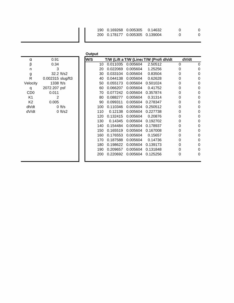
Validation Point 5
Input
α 0.91 W/S T/W Lapse Rate
β 0.34 10 2.5215 Fuel/Payload
n 3 20 1.2801 Load Factor
g 32.2 ft/s2 30 0.8737 Gravity
R 0.002315 slug/ft3 40 0.676 Excrecence Drag
Velocity 1338 ft/s 50 0.5618 Freesteam Velocity
q 2072.207 psf 60 0.4893 Dynamic Pressure
CD0 0.011 70 0.4407 Min Drag
K1 2 80 0.407 Drag Polar Coeffecient
K2 0.005 90 0.3832 Drag Polar Coeffecient
dh/dt 0 ft/s 100 0.3664 Vertical Velocity
dV/dt 0 ft/s2 110 0.3547 Vertical Acceleration
120 0.346758
130 0.341736
140 0.339008
150 0.338114
160 0.338712
170 0.340537
180 0.343386
190 0.347096
200 0.351539

Calculated using this Spreadsheet Tool
Output
α 0.33 W/S T/W (Lift and Induced Drag Component)T/W (Linear Drag Component)T/W (Profile Drag Component)dh/dt dV/dt
β 0.57 10 0.037606 0.022455 2.548 0.086985 0.096556
n 2.6 20 0.075212 0.022455 1.274 0.086985 0.096556
g 32.2 ft/s2 30 0.112818 0.022455 0.849333 0.086985 0.096556
R 0.001832 slug/ft3 40 0.150424 0.022455 0.637 0.086985 0.096556
Velocity 695 ft/s 50 0.18803 0.022455 0.5096 0.086985 0.096556
q 442.4509 psf 60 0.225636 0.022455 0.424667 0.086985 0.096556
CD0 0.019 70 0.263242 0.022455 0.364 0.086985 0.096556
K1 0.25 80 0.300848 0.022455 0.3185 0.086985 0.096556
K2 0.005 90 0.338454 0.022455 0.283111 0.086985 0.096556
dh/dt 35 ft/s 100 0.37606 0.022455 0.2548 0.086985 0.096556
dV/dt 1.8 ft/s2 110 0.413666 0.022455 0.231636 0.086985 0.096556
120 0.451272 0.022455 0.212333 0.086985 0.096556
130 0.488878 0.022455 0.196 0.086985 0.096556
140 0.526484 0.022455 0.182 0.086985 0.096556
150 0.56409 0.022455 0.169867 0.086985 0.096556
160 0.601696 0.022455 0.15925 0.086985 0.096556
170 0.639302 0.022455 0.149882 0.086985 0.096556
180 0.676908 0.022455 0.141556 0.086985 0.096556
190 0.714514 0.022455 0.134105 0.086985 0.096556
200 0.75212 0.022455 0.1274 0.086985 0.096556
Output
α 0.69 W/S T/W (Lift and Induced Drag Component)T/W (Linear Drag Component)T/W (Profile Drag Component)dh/dt dV/dt
β 0.72 10 0.011792 0.005217 0.692797 0.087582 0.058331
n 1 20 0.023584 0.005217 0.346399 0.087582 0.058331
g 32.2 ft/s2 30 0.035376 0.005217 0.230932 0.087582 0.058331
R 0.001832 slug/ft3 40 0.047168 0.005217 0.173199 0.087582 0.058331
Velocity 417 ft/s 50 0.05896 0.005217 0.138559 0.087582 0.058331
q 159.2823 psf 60 0.070752 0.005217 0.115466 0.087582 0.058331
CD0 0.03 70 0.082544 0.005217 0.098971 0.087582 0.058331
K1 0.25 80 0.094336 0.005217 0.0866 0.087582 0.058331
K2 0.005 90 0.106128 0.005217 0.076977 0.087582 0.058331
dh/dt 35 ft/s 100 0.11792 0.005217 0.06928 0.087582 0.058331
dV/dt 1.8 ft/s2 110 0.129712 0.005217 0.062982 0.087582 0.058331
120 0.141504 0.005217 0.057733 0.087582 0.058331
130 0.153296 0.005217 0.053292 0.087582 0.058331
140 0.165088 0.005217 0.049486 0.087582 0.058331
150 0.17688 0.005217 0.046186 0.087582 0.058331
160 0.188672 0.005217 0.0433 0.087582 0.058331
170 0.200464 0.005217 0.040753 0.087582 0.058331

180 0.212256 0.005217 0.038489 0.087582 0.058331
190 0.224048 0.005217 0.036463 0.087582 0.058331
200 0.235841 0.005217 0.03464 0.087582 0.058331
Output
α 0.69 W/S T/W (Lift and Induced Drag Component)T/W (Linear Drag Component)T/W (Profile Drag Component)dh/dt dV/dt
β 0.72 10 0.000916 0.002087 1.188573 0.027296 0.058331
n 1 20 0.001833 0.002087 0.594286 0.027296 0.058331
g 32.2 ft/s2 30 0.002749 0.002087 0.396191 0.027296 0.058331
R 0.001832 slug/ft3 40 0.003665 0.002087 0.297143 0.027296 0.058331
Velocity 1338 ft/s 50 0.004582 0.002087 0.237715 0.027296 0.058331
q 1639.864 psf 60 0.005498 0.002087 0.198095 0.027296 0.058331
CD0 0.005 70 0.006414 0.002087 0.169796 0.027296 0.058331
K1 0.2 80 0.00733 0.002087 0.148572 0.027296 0.058331
K2 0.002 90 0.008247 0.002087 0.132064 0.027296 0.058331
dh/dt 35 ft/s 100 0.009163 0.002087 0.118857 0.027296 0.058331
dV/dt 1.8 ft/s2 110 0.010079 0.002087 0.108052 0.027296 0.058331
120 0.010996 0.002087 0.099048 0.027296 0.058331
130 0.011912 0.002087 0.091429 0.027296 0.058331
140 0.012828 0.002087 0.084898 0.027296 0.058331
150 0.013745 0.002087 0.079238 0.027296 0.058331
160 0.014661 0.002087 0.074286 0.027296 0.058331
170 0.015577 0.002087 0.069916 0.027296 0.058331
180 0.016493 0.002087 0.066032 0.027296 0.058331
190 0.01741 0.002087 0.062556 0.027296 0.058331
200 0.018326 0.002087 0.059429 0.027296 0.058331
Output
α 0.82 W/S T/W (Lift and Induced Drag Component)T/W (Linear Drag Component)T/W (Profile Drag Component)dh/dt dV/dt
β 0.87 10 0.008909 0.005305 2.780072 0 0
n 1 20 0.017818 0.005305 1.390036 0 0
g 32.2 ft/s2 30 0.026727 0.005305 0.926691 0 0
R 0.002315 slug/ft3 40 0.035635 0.005305 0.695018 0 0
Velocity 1338 ft/s 50 0.044544 0.005305 0.556014 0 0
q 2072.207 psf 60 0.053453 0.005305 0.463345 0 0
CD0 0.011 70 0.062362 0.005305 0.397153 0 0
K1 2 80 0.071271 0.005305 0.347509 0 0
K2 0.005 90 0.08018 0.005305 0.308897 0 0
dh/dt 0 ft/s 100 0.089088 0.005305 0.278007 0 0
dV/dt 0 ft/s2 110 0.097997 0.005305 0.252734 0 0
120 0.106906 0.005305 0.231673 0 0
130 0.115815 0.005305 0.213852 0 0
140 0.124724 0.005305 0.198577 0 0
150 0.133633 0.005305 0.185338 0 0
160 0.142542 0.005305 0.173755 0 0
170 0.15145 0.005305 0.163534 0 0
180 0.160359 0.005305 0.154448 0 0
190 0.169268 0.005305 0.14632 0 0
200 0.178177 0.005305 0.139004 0 0
Output
α 0.91 W/S T/W (Lift and Induced Drag Component)T/W (Linear Drag Component)T/W (Profile Drag Component)dh/dt dV/dt
β 0.34 10 0.011035 0.005604 2.50512 0 0
n 3 20 0.022069 0.005604 1.25256 0 0
g 32.2 ft/s2 30 0.033104 0.005604 0.83504 0 0
R 0.002315 slug/ft3 40 0.044138 0.005604 0.62628 0 0
Velocity 1338 ft/s 50 0.055173 0.005604 0.501024 0 0
q 2072.207 psf 60 0.066207 0.005604 0.41752 0 0
CD0 0.011 70 0.077242 0.005604 0.357874 0 0
K1 2 80 0.088277 0.005604 0.31314 0 0
K2 0.005 90 0.099311 0.005604 0.278347 0 0
dh/dt 0 ft/s 100 0.110346 0.005604 0.250512 0 0
dV/dt 0 ft/s2 110 0.12138 0.005604 0.227738 0 0
120 0.132415 0.005604 0.20876 0 0
130 0.14345 0.005604 0.192702 0 0
140 0.154484 0.005604 0.178937 0 0
150 0.165519 0.005604 0.167008 0 0
160 0.176553 0.005604 0.15657 0 0
170 0.187588 0.005604 0.14736 0 0
180 0.198622 0.005604 0.139173 0 0
190 0.209657 0.005604 0.131848 0 0
200 0.220692 0.005604 0.125256 0 0

T/W Total
2.7916
1.5552
1.1681
0.9934
0.9036
0.8563
0.8332
0.8253
0.8276
0.8369
0.8513
0.8696
0.8909
0.9145
0.9400
0.9669
0.9952
1.0245
1.0546
1.0855
T/W Total
0.8557
0.5211
0.4174
0.3715
0.3487
0.3373
0.3326
0.3321
0.3342
0.3383
0.3438
0.3504
0.3577
0.3657
0.3742
0.3831
0.3923
0.0
0.5
1.0
1.5
2.0
2.5
3.0
0 50 100 150
T/W
W/S
Validation Case 1: W/S and T/W
Calculated Using Mattingly -Master Equation
Provided Validation Points fromGA TECH
0.5
1.0
1.5
2.0
2.5
3.0
T/W
W/S
Validation Case 2: W/S and T/W
Calculated Using Mattingly -Master Equation
Provided Validation Points fromGA TECH

0.4019
0.4116
0.4216
T/W Total
1.2772
0.6838
0.4867
0.3885
0.3300
0.2913
0.2639
0.2436
0.2280
0.2157
0.2058
0.1978
0.1911
0.1854
0.1807
0.1767
0.1732
0.1702
0.1677
0.1655
T/W Total
2.7943
1.4132
0.9587
0.7360
0.6059
0.5221
0.4648
0.4241
0.3944
0.3724
0.3560
0.3439
0.3350
0.3286
0.3243
0.3216
0.3203
0.3201
0.0
0 50 100 150
W/S
0.0
0.5
1.0
1.5
2.0
2.5
3.0
0 50 100 150
T/W
W/S
Validation Case 3: W/S and T/W
Calculated Using Mattingly -Master Equation
Provided Validation Points fromGA TECH
0.0
0.5
1.0
1.5
2.0
2.5
3.0
T/W
W/S
Validation Case 4: W/S and T/W
Calculated Using Mattingly -Master Equation
Provided Validation Points fromGA TECH

0.3209
0.3225
T/W Total
2.5218
1.2802
0.8737
0.6760
0.5618
0.4893
0.4407
0.4070
0.3833
0.3665
0.3547
0.3468
0.3418
0.3390
0.3381
0.3387
0.3406
0.3434
0.3471
0.3516
0.0
0 50 100 150
W/S
0.0
0.5
1.0
1.5
2.0
2.5
3.0
0 50 100 150
T/W
W/S
Validation Case 5: W/S and T/W
Calculated Using Mattingly -Master Equation
Provided Validation Points fromGA TECH

200

200
200

200
200

Step 1 Payload Calculations, WPL Notes/Sources:
3,240 lbs Source: "2006-2007 AIAA Graduate Team Aircraft Design Competition - Modifiied RFP"
5,000 lbs
12,000 lbs
Total WPL 12,000 lbs Enter Payload based on above values, and Desired Mission (for baseline misson, assume worst case external stores)
Crew Weight
250 lbs Source: "2006-2007 AIAA Graduate Team Aircraft Design Competition - Modifiied RFP"
Total WCREW 250 lbs
Step 2 Weight Take Off Guess Based on Historical Data, WTO_GUESS
W_PL W_TO V_MAX Range Source: Taylor, J.W.R, Jane's All The World Aircraft Published Annually by: Jane's Publishing Company, (Issues used: 1945/45, 1968/84)
(lbs) (lbs) (kts) (nm) Source: Roskam, "Airplane Design, Part I: Preliminary Sizing of Airplanes", 1985, pg 60
15,000 50,000 450 540
17,000 60,400 689 1,700
16,000 58,400 600 750
Average: 16,000 56,267 580 997 Some initial guess for TOGW, will only be used for reference, program automatically calculates TOGW based on historical data
WTO_GUESS 59,488 lbs Later this will be iterated to find weight empty
Step 3 Mission Fuel Weight Fractions, WF Source: Roskam, "Airplane Design, Part I: Preliminary Sizing of Airplanes", 1985, pg 12
Climb 1
Range Credit 24.5 nm Assume 10,000 ft/min climb (from RFP) and 350 knot ground speed during climb (from Roskam page 62); therefore, Rclimb = Alt./(10K/min)*350knots
Cruise 1
Rcr, Cruise Range 775.5 nm 800 nm specified in RFP - climb 1 range
Altitude 42,000 ft
Temperature @ Alt, T -90.6o F
Delta 0.1668
Theta 0.7116
Mission Analysis
Ammunition Weight (1.62 lbs x 2000 rounds)
F.R. A10A
Grumman A6
Internal Stores Max
External Stores Max
Crew (1x250lbs)
GD GAU-8 30-mm Cannon is part of weight empty
External Stores is deemed the limiting case
Tornado F.Mk2
Aircraft Type

Step 1 Payload Calculations, WPL Notes/Sources:
3,240 lbs Source: "2006-2007 AIAA Graduate Team Aircraft Design Competition - Modifiied RFP"
5,000 lbs
12,000 lbs
Total WPL 12,000 lbs Enter Payload based on above values, and Desired Mission (for baseline misson, assume worst case external stores)
Crew Weight
250 lbs Source: "2006-2007 AIAA Graduate Team Aircraft Design Competition - Modifiied RFP"
Total WCREW 250 lbs
Step 2 Weight Take Off Guess Based on Historical Data, WTO_GUESS
W_PL W_TO V_MAX Range Source: Taylor, J.W.R, Jane's All The World Aircraft Published Annually by: Jane's Publishing Company, (Issues used: 1945/45, 1968/84)
(lbs) (lbs) (kts) (nm) Source: Roskam, "Airplane Design, Part I: Preliminary Sizing of Airplanes", 1985, pg 60
15,000 50,000 450 540
17,000 60,400 689 1,700
16,000 58,400 600 750
Average: 16,000 56,267 580 997 Some initial guess for TOGW, will only be used for reference, program automatically calculates TOGW based on historical data
WTO_GUESS 62,414 lbs Later this will be iterated to find weight empty
Step 3 Mission Fuel Weight Fractions, WF Source: Roskam, "Airplane Design, Part I: Preliminary Sizing of Airplanes", 1985, pg 12
Climb 1
Range Credit 24.5 nm Assume 10,000 ft/min climb (from RFP) and 350 knot ground speed during climb (from Roskam page 62); therefore, Rclimb = Alt./(10K/min)*350knots
Cruise 1
Rcr, Cruise Range 775.5 nm 800 nm specified in RFP - climb 1 range
Altitude 42,000 ft
Temperature @ Alt, T -90.6o F
Delta 0.1668
Theta 0.7116
Mission Analysis
Ammunition Weight (1.62 lbs x 2000 rounds)
F.R. A10A
Grumman A6
Internal Stores Max
External Stores Max
Crew (1x250lbs)
GD GAU-8 30-mm Cannon is part of weight empty
External Stores is deemed the limiting case
Tornado F.Mk2
Aircraft Type

0.0
0.2
0.4
0.6
0.8
1.0
1.2
1.4
0 25 50 75 100 125 150 175 200

0.0
0.2
0.4
0.6
0.8
1.0
1.2
1.4
0 25 50 75 100 125 150 175 200


![Tits Fixed Wing Alternatives for COIN[1]](https://static.fdocuments.net/doc/165x107/54ff38894a7959ec0f8b4bf7/tits-fixed-wing-alternatives-for-coin1.jpg)