FIRESTOP SUBMITTAL PACKAGE - Acousti Firestop · Flat Slab Sealant. Certificate of ... Standard...
23
FIRESTOP SUBMITTAL PACKAGE Project: Date: Submitted by: 210 Evans Way • Somerville, NJ 08876 • (800) 992-1180 • (908) 526-8000 • Fax (908) 526-9623 www.stifirestop.com Flat Slab Sealant
Transcript of FIRESTOP SUBMITTAL PACKAGE - Acousti Firestop · Flat Slab Sealant. Certificate of ... Standard...

FIRESTOP SUBMITTAL PACKAGE
Project:
Date:
Submitted by:
210 Evans Way • Somerville, NJ 08876 • (800) 992-1180 • (908) 526-8000 • Fax (908) 526-9623
www.stifirestop.com
Flat Slab Sealant

Certificate of Conformance • Technical Service 1-800-992-1180 • www.stifirestop.com
SpecSeal® Series SSS Intumescent Sealant SpecSeal® Series LCI Intumescent Sealant SpecSeal® Series LC Firestop Sealant
SpecSeal® Series ES Elastomeric Sealant SpecSeal® Series SIL300 Silicone Sealant SpecSeal® Series SIL300SL Silicone Sealant
Pensil® PEN300 Silicone Sealant Pensil® PEN300SL Silicone Sealant Pensil® PEN200 Silicone Foam
BlazeStop™ WF300 Firestop Caulk SpecSeal® Series AS200 Elastomeric Spray SpecSeal® Series FT Fast Tack™ Firestop Spray
SpecSeal® Series SSP Putty & Putty Pads SpecSeal® Series EP PowerShield™ Box Insert SpecSeal® Series SSM Firestop Mortar
SpecSeal® Series SSB Firestop Pillows SpecSeal® Series CS Composite Sheet SpecSeal® Series SSW Wrap Strips
SpecSeal® Series LCC Firestop Collars SpecSeal® Series SSC Firestop Collars SpecSeal® Series RTC Firestop Collars
SpecSeal® Series FP Firestop Plugs SpecSeal® Series CD Cast-In Firestop Devices FyreFlange® Firestop Angle
EZ-Path® Series 22 EZ-Path® Series 33 EZ-Path® Series 44 or 44+
Ready® Sleeve Ready® Sleeve Split EZ-Path® Firestop Grommet
SpecSeal® Series SSAMW Mineral Wool SpecSeal® SpeedFlex® Fire Rated Joint Profile SpecSeal® Closet Flange Firestop Gasket
SpecSeal® Series CS105 Cable Spray SpecSeal® SpeedFlex® Track Top Gasket
Description:
SpecSeal® Firestop Products; Pensil® Silicone Sealants; EZ-Path® Fire Rated Pathways; Ready® Sleeve Firestop Sleeves; STI Firestop Products
Included Products:
These products are tested to one or more of the following standards:
• ASTM E814 (ANSI/UL1479) Standard Test Method for Fire Tests of Penetration Firestop Systems
• ASTM E1966 (ANSI/UL2079) Standard Test Method for Fire-Resistive Joint Systems
• ASTM E119 (ANSI/UL263) Standard Test Methods for Fire Tests of Building Construction and Materials
• ASTM E2307 Standard Test Method for Determining Fire Resistance of Perimeter Fire Barrier Systems Using Intermediate Scale, Multi-Story Test Apparatus
• ASTM E1399 Standard Test Method for Cyclic Movement and Measuring the Minimum and Maximum Joint Widths of Architectural Joint Systems
• ASTM E84 (ANSI/UL723) Standard Test Method for Surface Burning Characteristics of Building Materials
• CAN/ULC S115 Standard Method of Fire Tests of Firestop Systems
• CAN/ULC S101 Standard Methods of Fire Endurance Tests of Building Construction and Materials
Chemical Content Statement:
No asbestos, PCB’s, lead, or water-soluble intumescent ingredients are used or contained in these products.
Paul M. JankowskiQuality Control Manager
James P. Stahl Jr., CFPSVice President of Engineering
GENERAL CERTIFICATE OF CONFORMANCEJUNE 2013

Assembly Ratings - 1 and 2 Hr (See Item 2)Maximum Joint Width - 3/4 In.
Class II Movement Capabilities - 25% Compression
1. Floor Assembly - Min 4-1/2 in. (114 mm) thick steel-reinforced lightweight or normal weight (100-150 pcf or 1600-2400 kg/m3)structural concrete. Floor may also be constructed of any UL Classified hollow-core Precast Concrete Units*.
See Precast Concrete Units (CFTV) in Fire Resistance Directory for names of manufacturers.
2. Wall Assembly - The 1 or 2 hr fire-rated gypsum board/stud wall assembly shall be constructed of the materials and in themanner described in the individual U400 or V400 Series Wall and Partition Design in the UL Fire Resistance Directory and shallinclude the following construction features:
A. Steel Floor and Ceiling Runners - Floor and ceiling runners of wall assembly shall consist of galv steel channels sized toaccommodate steel studs (Item 2B) with min 1-1/4 in. (32 mm) long flanges. Ceiling runner secured to concrete floor slabwith steel masonry anchors spaced max 24 in. (610 mm) OC.
A1. Light Gauge Framing* - Clipped Ceiling Runner - As an alternate to the ceiling runner in Item 2A, clipped runner toconsist of galv steel channel with clips preformed in track flanges which positively engage the inside flange of the steelstuds (Item 2B). Track sized to accommodate steel studs (Item 2B). Track flanges to be min 2-1/2 in. (64 mm) long.Clipped ceiling runner secured to concrete floor slab with steel masonry anchors spaced max 24 in. (610 mm) OC.
CALIFORNIA EXPANDED METAL PRODUCTS CO - CST
TOTAL STEEL SOLUTIONS L L C - Snap Trak
MARINO/WARE, DIV OF WARE INDUSTRIES
INC - Type SLT
R Created or Revised:Reproduced courtesy of Underwriters Laboratories, Inc.
PAGE OF(800)992-1180 (908)526-8000 FAX (908)231-8415 E-Mail:[email protected] Website:www.stifirestop.com
June 28, 2011
1 2
Ì75HWDÇ$sÈACÇ&<+YÎ
HW-D-0483
2C
3B
1
2C
1
3B
2B
2A
2B
2C
SECTION A-A
2A3B
1A
A

A2. Light Gauge Framing* - Slotted Ceiling Runner - As an alternate to the ceiling runner in Item 2A, ceiling runner toconsist of galv steel channel with slotted flanges sized to accommodate steel studs (Items 2B). Ceiling runner secured toconcrete floor slab with steel masonry anchors spaced max 24 in. (610 mm) OC.
BRADY CONSTRUCTION INNOVATIONS INC,
DBA SLIPTRACK SYSTEMS - SLP-TRK
CLARKWESTERN BUILDING SYSTEMS INC - Type SLT, SLT-H
METAL-LITE INC - The System
A3. Light Gauge Framing* - Vertical Deflection Ceiling Runner - As an alternate to the ceiling runner in Item 2A, verticaldeflection ceiling runner to consist of galv steel channel with slotted vertical deflection clips mechanically fastened withinrunner. Slotted clip provided with step bushings for permanent fastening of steel studs. Flanges sized to accommodatesteel studs (Item 2B). Vertical deflection ceiling runner secured to concrete floor slab with steel masonry anchors spacedmax 24 in. (610 mm) OC.
THE STEEL NETWORK INC - VertiTrack VTD358, VTD400, VTD600 and VTD800
A4. Light Gauge Framing* - Notched Ceiling Runner - As an alternate to the ceiling runners in Items 2A through 2A3,notched ceiling runners to consist of C-shaped galv steel channel with notched return flanges sized to accommodate steelstuds (Item 2B). Notched ceiling runner secured to concrete floor slab with steel masonry anchors spaced max 24 in. (610mm) OC.
OLMAR SUPPLY INC - Type SCR
B. Studs - Steel studs to be min 3-1/2 in. (89 mm) wide. Studs cut 1/2 in. (13 mm) to 3/4 in. (19 mm) less in length thanassembly height with bottom nesting in and resting on floor runner and with top nesting in ceiling runner withoutattachment. When deflection channel (Item 3A) is used, steel studs attached to ceiling runner with sheet metal screwslocated 1/2 in. (13 mm) below the bottom of the deflection channel. When slotted ceiling runner (Item 2A2) is used, steelstuds secured to slotted ceiling runner with No. 8 by 1/2 in. (13 mm) long wafer head steel screws at midheight of slot oneach side of wall. When vertical deflection ceiling runner (Item 2A3) is used, steel studs secured to slotted verticaldeflection clips, through bushings, with steel screws at midheight of each slot. Stud spacing not to exceed 24 in. (610 mm)OC.
C. Gypsum Board* - Gypsum board sheets installed to a min total thickness of 5/8 in. (16 mm) and 1-1/4 in. (32 mm) oneach side of wall for 1 and 2 hr fire rated assemblies, respectively. Wall to be constructed as specified in the individualWall and Partition Design in the UL Fire Resistance Directory, except that a max 3/4 in. (19 mm) gap shall be maintainedbetween the top of the gypsum board and the bottom surface of the floor. In addition, the top row of screws shall beinstalled into the steel studs 1/2 to 1 in. (13 to 25 mm) below the bottom edge of the ceiling runner flange.
The hourly fire rating of the joint system is dependent on the hourly fire rating of the wall assembly in which it isinstalled.
3. Joint System - Max separation between bottom of floor and top of wall is 3/4 in. (19 mm). The joint system is designed toaccommodate a max 25 percent compression from its installed width. . The joint system consists of the following:
A. Forming Material - (Optional, Not Shown) - In 2 hr fire rated wall assemblies, polyethylene backer rod, mineral wool battinsulation or fiberglass batt insulation friction fit into joint opening.
B. Fill, Void or Cavity Material* - Sealant - Min 5/8 in. (16 mm) thickness of fill material applied within joint opening on bothsides of wall, flush with both surfaces of wall. As an option in 1 hr fire rated walls, bond breaker tape applied to ceilingchannel (Item 2A) prior to installation of fill material.
SPECIFIED TECHNOLOGIES INC - SpecSeal LC150 Sealant, SpecSeal LE600 Sealant
*Bearing the UL Classification Mark
R Created or Revised:Reproduced courtesy of Underwriters Laboratories, Inc.
PAGE OF(800)992-1180 (908)526-8000 FAX (908)231-8415 E-Mail:[email protected] Website:www.stifirestop.com
June 28, 2011
2 2HW-D-0483

Assembly Ratings - 1 and 2 Hr (See Items 2 and 3B)Maximum Joint Width - 3/4 In.
Class II Movement Capabilities-25 Percent Compression
1. Floor Assembly - Min 4-1/2 in. (114 mm) thick reinforced lightweight or normal weight (100-150 pcf or 1600-2400 kg/m3 )structural concrete. Floor may also be constructed of any UL Classified hollow-core Precast Concrete Units*.
See Precast Concrete Units (CFTV) in Fire Resistance Directory for names of manufacturers.
2. Shaft Wall Assembly - The 1 or 2 hr fire rated shaft wall assembly shall be constructed of the materials and in the mannerdescribed in the individual U400 or V400-Series Wall and Partition Design in the UL Fire Resistance Directory and shall includethe following construction features:
A. Floor and Wall Runners - (Not Shown) - "J"-shaped runner, min 2-1/2 in. (64 mm) wide with unequal legs of 1 in. (25mm) and 2 in. (51 mm), fabricated from min 24 MSG galv steel. Runners positioned with short leg toward finished side ofwall. Runners attached to walls and floor with steel fasteners spaced max 24 in. (610 mm) OC. As an alternate to the"J"-shaped runner, a min 2-1/2 in. (64 mm) wide by 1 or 1-1/4 in. (25 or 32 mm) deep channel formed from min 24 MSGgalv steel may be used for the floor runner.
B. Steel Floor And Ceiling Runners - Floor and ceiling runners of wall assembly shall consist of galv steel channels sizedto accommodate steel "C-H" studs. Flange height of ceiling runner shall be min 1/2 in. (13 mm) greater than nom jointwidth. Ceiling runner secured with steel masonry anchors spaced max 24 in. (610 mm) OC.
B1. Light Gauge Framing* - Slotted Ceiling Track - As an option to Item 2B, slotted ceiling track shall consist of galv steelchannels with slotted flanges. Slotted ceiling track sized to accommodate steel "C-H" studs (Items 2C). Attached toconcrete at ceiling with steel fasteners spaced max 12 in. OC (305 mm).
BRADY CONSTRUCTION INNOVATIONS INC, DBA SLIPTRACK SYSTEMS - SLP-TRK
CALIFORNIA EXPANDED METAL PRODUCTS CO - CST
CLARKDIETRICH BUILDING SYSTEMS - Type SLT, SLT-H
MARINO/WARE, DIV OF WARE INDUSTRIES INC - Type SLT
SCAFCO STEEL STUD MANUFACTURING CO
TELLING INDUSTRIES L L C - True-Action Deflection Track
R Created or Revised:Reproduced courtesy of Underwriters Laboratories, Inc.
PAGE OF(800)992-1180 (908)526-8000 FAX (908)231-8415 E-Mail:[email protected] Website:www.stifirestop.com
March 14, 2014
1 2
Ì73HWDÇ$uÈACÇ#..uÎ
HW-D-0485
2B
2C
3B3A
2C
2B
2D
3B 2B
2C
2D
3B
2E
2D2E
2E 1
1

C. Steel Studs - "C-H"-shaped steel studs to be min 2-1/2 in. (64 mm) wide and formed of min 24 MSG galv steel. Studs cut1/2 to 3/4 in. (13 to 19 mm) less in length than assembly height with bottom nesting in and resting on floor runner and withtop nesting in ceiling runner or slotted ceiling track. Studs spaced 24 in. (610 mm) OC. After installation of gypsum boardliner panels (Item 2D), studs secured to flange of floor runner on finished side of wall only with No. 6 by 1/2 in. (13 mm)long self-drilling, self-tapping steel screws. Studs secured to flange of slotted ceiling track on finished side of wall only withNo. 8 by 1/2 in. (13 mm) long self-drilling, self-tapping wafer head steel screws at slot midheight.
D. Gypsum Board* - 1 in. (25 mm) thick by 24 in. (610 mm) wide gypsum board liner panels. Panels cut 1 in. (25 mm) less inlength than floor to ceiling height. Vertical edges inserted in "H"-shaped section of "C-H" studs. Free edge of end panelsattached to long leg of "J" runner (Item 2A) with 1-5/8 in. (41 mm) long Type S steel screws spaced max 12 in. (305 mm)OC.
E. Gypsum Board* - Gypsum board sheets, 1/2 or 5/8 in. (13 or 16 mm) thick, applied vertically or horizontally in one or twolayers on finished side of wall as specified in the individual U400 or V400-Series Wall and Partition Design. A max 1 in. (25mm) gap shall be maintained between the top of the gypsum board and the bottom surface of the concrete floor. Thescrews attaching the gypsum board layers to the C-H studs shall be located 1 in. (25 mm) below the bottom of the slottedceiling track (Item 2C). No gypsum board attachment screws are to penetrate the slotted ceiling track.
The hourly fire rating of the joint system is equal to the hourly fire rating of the wall.
3. Joint System - Max separation between bottom of floor and top of liner panel (Item 2D) and between bottom of floor and top ofgypsum board sheets (Item 2E) at time of installation of joint system is 3/4 in. (19 mm). The joint system is designed toaccommodate a maximum 25 percent compression only from its installed width. The joint system consists of bond breaker tapeand sealant, as follows:
A. Bond Breaker Tape - Polyethylene tape supplied in rolls. Tape applied to flanges of slotted ceiling track (Item 2D) toprevent bonding of the sealant at points other than the top and bottom of the linear gap. Bond breaker tape is optional.
B. Fill, Void or Cavity Material* - Sealant - Min 1 in. (25 mm) depth of sealant to be installed to fill linear gap between top ofgypsum board liner panel (Item 2D) and top inside surface of slotted ceiling track (Item 2B) prior to installation of gypsumboard sheets on finished side of wall. For 1 Hr walls, min 5/8 in. (16 mm) depth of sealant to be installed to fill linear gapbetween top of gypsum board sheet (Item 2E) and bottom of concrete floor. For 2 Hr walls, min 1 in. (25 mm) depth ofsealant to be installed to fill linear gap between top of gypsum board sheets (Item 2E) and bottom of concrete floor.
SPECIFIED TECHNOLOGIES INC - SpecSeal LC150 Sealant, SpecSeal LE600 Sealant
*Bearing the UL Classification Mark
R Created or Revised:Reproduced courtesy of Underwriters Laboratories, Inc.
PAGE OF(800)992-1180 (908)526-8000 FAX (908)231-8415 E-Mail:[email protected] Website:www.stifirestop.com
March 14, 2014
2 2HW-D-0485

Assembly Ratings - 1 and 2 Hr (See Item 2)Nominal Joint Width - 3/4 in. or 1 in. (See Item 3)L Rating At Ambient - Less Than 1 CFM/Lin FtL Rating At 400 F - Less Than 1 CFM/Lin Ft
Class II and III Movement Capabilities - 19% or 100% Compression or Extensionor 25% Compression (See Item 3A or 3B1)
1. Floor Assembly - Min 4-1/2 in. (114 mm) thick steel reinforced lightweight or normal weight (100-150 pcf or 1600-2400 kg/m3)structural concrete. Floor may also be constructed of any min 6 in. (152 mm) thick UL Classified hollow-core Precast ConcreteUnits*. See Precast Concrete Units (CFTV) category in the Fire Resistance Directory for names manufacturers.
The hourly fire rating of the floor assembly shall be equal or greater than the hourly fire rating of the wall assembly.
2. Wall Assembly - The 1 or 2 hr fire rated gypsum board/stud wall assembly shall be constructed of the materials and in themanner described in the individual U400 or V400 Series Wall and Partition Design in the UL Fire Resistance Directory and shallinclude the following construction features:
A. Steel Floor and Ceiling Runners - Floor and ceiling runners of wall assembly shall consist galv steel channels sized toaccommodate steel studs (Item 2B). Ceiling runner to be provided with min 2 in. (51 mm) to max 3 in. (76 mm) flanges.
B. Studs - Steel studs to be min 3-1/2 in. (89 mm) wide. Studs cut 1/2 in. to 3/4 in. (13 to 19 mm) less in length thanassembly height with bottom nesting in and secured to floor runner. Studs to nest in ceiling runner without attachmentunless slotted ceiling runner is used. When slotted ceiling runner (Item 2A1) is used, steel studs secured to slotted ceilingrunner with No. 8 by 1/2 (13 mm) long wafer head steel screws at mid-height of slot on each side of wall.
C. Gypsum Board* - Gypsum board sheets installed to a min total 5/8 in. (16 mm) or 1-1/4 in. (32 mm) thickness on eachside of wall for 1 hr and 2 hr fire rated assemblies, respectively. Wall to be constructed as specified in the individual U400or V400 Series Design in the UL Fire Resistance Directory except that a max 3/4 or 1 in. (19 or 25 mm) gap shall bemaintained between the top of the gypsum board and the bottom of the floor. The gypsum board on the shaft side shallextend flush with bottom of floor assembly. The screws attaching the gypsum board to the studs along the top of the wallshall be located 1 in. (25 mm) below the bottom of the ceiling runner. No gypsum board attachment screws shall be driveninto the ceiling runner.
The hourly fire rating of the joint system is equal to the hourly fire rating of the wall.
3. Joint System - Max separation between bottom of floor and top of gypsum board panels (non-shaft side) and between gypsumboard panels (shaft side) at time of installation is 3/4 or 1 in. (19 or 25 mm). When Item 3B1 is used in lieu of the mineral woolstrips described in Item 3B, the maximum joint width is 3/4 in. and the movement capability of the joint system is 100 percentcompression or extension. Otherwise, the movement capability of the joint system is 19 percent compression or extension. Thejoint system shall consist of forming and fill materials, as follows:
R Created or Revised:Reproduced courtesy of Underwriters Laboratories, Inc.
PAGE OF(800)992-1180 (908)526-8000 FAX (908)231-8415 E-Mail:[email protected] Website:www.stifirestop.com
June 17, 2010
1 2
Ì75HWDÇ&2&1*TÎ
HW-D-0618
1
3A
3A
2B
3A
2A
2C

A. Fill, Void or Cavity Material* - Min 1/2 in. (13 mm) depth of sealant applied within the joint between gypsum board sheetsand between gypsum board and concrete at top and bottom of floor. When gypsum board abuts top surface of floor, the fillmaterial is optional unless required by local code. When gypsum board on shaft side is continuous without a joint openingto allow for movement, the joint system shall be limited to static conditions.
SPECIFIED TECHNOLOGIES INC - SpecSeal ES Sealant or LC150 Sealant
B. Forming Material* - (Not Shown) - As an alternate to Item 3A when used in conjunction with Item 3C, strips of nom 4 pcf(64 kg/m3) mineral wool cut to a width equal to thickness of gypsum board layers are compressed 50 percent in thicknessand installed flush with wall surfaces. When gypsum board abuts top surface of floor, the forming material is optionalunless required by local code.
B1. Forming Material* - (Not Shown) - As an option to Item 3B when the nominal joint width is 3/4 in. (19 mm) or less, nom3/16 in. (4.8 mm) thick by 4 in. (102 mm) high joint forming material profile installed on both sides of the wall assembly.Profile installed by first marking a line across the top of the wall 3 in. (76 mm) below the bottom plane of the steel floor orroof deck valleys. Joint profile material positioned with its top edge against both the underside of the spray-appliedfire-resistive material with its bottom edge on the line scribed on the wall assembly. Bottom of the joint profile attached togypsum board with nom 1/2 in. (13 mm) long steel staples spaced not greater than 8 in. (203 mm) OC. Adjoining lengthsof profile to overlap approx 3/4 in. (19 mm) at rabbeted ends. When Item 3C1 is used, the movement capability of the jointsystem is 100 percent compression or extension.
SPECIFIED TECHNOLOGIES INC - SpecSeal Speed Flex Joint Profile
C. Fill, Void or Cavity Material* - (Not Shown) - When Item 3B is used, min 1/8 in. (3.2 mm) wet or 1/16 in. (1.6 mm dry)thickness of spray applied atop mineral wool with 1/2 in. (13 mm) overlap onto surrounding substrates. When gypsumboard abuts top surface of floor, the fill material is optional unless required by local code.
SPECIFIED TECHNOLOGIES INC - SpecSeal AS200 Elastomeric Spray
*Bearing the UL Classification Mark
R Created or Revised:Reproduced courtesy of Underwriters Laboratories, Inc.
PAGE OF(800)992-1180 (908)526-8000 FAX (908)231-8415 E-Mail:[email protected] Website:www.stifirestop.com
June 17, 2010
2 2HW-D-0618

Assembly Ratings - 1 and 2 Hr (See Item 2)Nominal Joint Width - 3/4 in.
L Rating At Ambient - Less Than 1 CFM/Lin FtL Rating At 400 F - Less Than 1 CFM/Lin Ft
Class II and III Movement Capabilities - 25% Compression or Extension or 25% Compression (See Item 3A)
1. Floor Assembly - Min 4-1/2 in. (114 mm) thick steel reinforced lightweight or normal weight (100-150 pcf or 1600-2400 kg/m3)structural concrete. Floor may also be constructed of any min 6 in. (152 mm) thick UL Classified hollow-core Precast ConcreteUnits*.
See Precast Concrete Units (CFTV) category in the Fire Resistance Directory for names manufacturers.
The hourly fire rating of the floor assembly shall be equal or greater than the hourly fire rating of the wall assembly.
2. Shaft Wall Assembly - The 1 or 2 hr fire rated shaft wall assembly shall be constructed of the materials and in the mannerdescribed in the individual U400 or V400 Series Wall and Partition Design in the UL Fire Resistance Directory. The wall shallinclude the following construction features:
A. Floor, Wall and Ceiling Runners - "J"-shaped runner, min 2-1/2 in. (64 mm) wide with unequal legs of 1 in. (25 mm) and2 in. (51 mm), fabricated from min 24 MSG galv steel. Runners positioned with short leg toward finished side of wall.Runners attached to walls and floor with steel fasteners spaced max 24 in. (610 mm) OC. As an alternate to the"J"-shaped runner, a min 2-1/2 in. (64 mm) wide by 1 or 1-1/4 in. (25 or 32 mm) deep channel formed from min 24 MSGgalv steel may be used for the floor runner.
A1. Light Gauge Framing* - Slotted Ceiling Track - (Not Shown) - Slotted ceiling track shall consist of galv steel channelswith slotted flanges. Slotted ceiling track sized to accommodate steel "C-H" studs (Items 2AC). Attached to concrete atceiling with steel fasteners spaced max 12 in. OC (305 mm).
BRADY CONSTRUCTION INNOVATIONS INC, DBA SLIPTRACK SYSTEMS - SLP-TRK
CALIFORNIA EXPANDED METAL PRODUCTS CO - CST
CLARKDIETRICH BUILDING SYSTEMS - Type SLT, SLT-H
SCAFCO STEEL STUD MANUFACTURING CO
STEELER INC - Steeler Slotted Ceiling Runner
TELLING INDUSTRIES L L C - True-Action Deflection Track
THE STEEL NETWORK INC - VertiTrack VT, series,250VT, 362VT, 400VT, 600VT and 800VT
R Created or Revised:Reproduced courtesy of Underwriters Laboratories, Inc.
PAGE OF(800)992-1180 (908)526-8000 FAX (908)231-8415 E-Mail:[email protected] Website:www.stifirestop.com
March 14, 2014
1 2
Ì74HWDÇ&NÈANÇ#..-Î
HW-D-0646
1
3A
Configuration 1
3A
2A
2C
3A
2B
3A
2A
2D
2C2D
1
Configuration 2
2B
2A
2A

B. Steel Studs - "C-H"-shaped steel studs to be min 2-1/2 in. (64 mm) wide and formed of min 24 MSG galv steel. Studs cut1/2 to 3/4 in. (13 to 19 mm) less in length than assembly height with bottom nesting in and resting on floor runner and withtop nesting in slotted ceiling track. Studs spaced 24 in. (610 mm) OC. After installation of gypsum board liner panels (Item2D), studs secured to flange of floor runner on finished side of wall only with No. 6 by 1/2 in. (13 mm) long self-drilling,self-tapping steel screws. Studs secured to flange of slotted ceiling track on finished side of wall only with No. 8 by 1/2 in.(13 mm) long self-drilling, self-tapping wafer head steel screws at slot midheight.
C. Gypsum Board* - 1 in. (25 mm) thick by 24 in. (610 mm) wide gypsum board liner panels as specified in the individualU400 or V400-Series Wall and Partition Design. Panels cut 1 in. (25 mm) less in length than floor to ceiling height. Verticaledges inserted in "H"-shaped section of "C-H" studs. Free edge of end panels attached to long leg of "J" runner (Item 2A)with 1-5/8 in. (41 mm) long Type S steel screws spaced max 12 in. (305 mm) OC.
D. Gypsum Board* - Gypsum board sheets, 1/2 or 5/8 in. (13 or 16 mm) thick, applied vertically or horizontally in one or twolayers on finished side of wall as specified in the individual U400 or V400-Series Wall and Partition Design. A max 1 in. (25mm) gap shall be maintained between the top of the gypsum board and the bottom surface of the concrete floor. Thescrews attaching the gypsum board layers to the C-H studs shall be located 1 in. (25 mm) below the bottom of the slottedceiling track (Item 2C). No gypsum board attachment screws are to penetrate the slotted ceiling track.
3. Joint System - Max separation between bottom of floor and top of gypsum board panels (non-shaft side) and between gypsumboard panels (shaft side) at time of installation is 3/4 in. (19 mm). The movement capability of the joint system is 25 percentcompression or extension. The joint system shall consist of forming and fill materials, as follows:
A. Fill, Void or Cavity Material* - Min 1 in. (25 mm) depth of sealant to be installed to fill linear gap between top of gypsumboard liner panel (Item 2C) and top inside surface of ceiling runner (Item 2A or 2A1) prior to installation of gypsum boardsheets on finished side of wall. For 1 Hr shaft walls, min 5/8 in. (16 mm) depth of sealant to be installed to fill linear gapbetween top of gypsum board sheet (Item 2D) and bottom of concrete floor for Configuration 1 or between the gypsumboard sheets (Item 2E)for Configuration 2. For 2 Hr shaft walls, min 1 in. (25 mm) depth of sealant to be installed to filllinear gap between top of gypsum board sheets (Item 2E) and bottom of concrete floor for Configuration 1 or between thegypsum board sheets in Configuration 2. When LC150 Sealant is used, the movement capability of the joint system is 25percent compression only.
SPECIFIED TECHNOLOGIES INC - SpecSeal ES Sealant or LC150 Sealant
*Bearing the UL Classification Mark
R Created or Revised:Reproduced courtesy of Underwriters Laboratories, Inc.
PAGE OF(800)992-1180 (908)526-8000 FAX (908)231-8415 E-Mail:[email protected] Website:www.stifirestop.com
March 14, 2014
2 2HW-D-0646

Assembly Ratings - 1 and 2 Hr (See Item 2)L Rating At Ambient - Less Than 1 CFM/Lin Ft (See Item 3B)L Rating At 400°F - Less Than 1 CFM/Lin Ft (See Item 3B)
Joint Width - 3/4 In. Max
1. Floor Assembly - Min 4-1/2 in. (114 mm) thick reinforced lightweight or normal weight (100-150 pcf or 1600-2400 kg/m3)structural concrete. Floor may also be constructed of any 6 in. (152 mm) thick UL Classified hollow-core Precast ConcreteUnits*.See Precast Concrete Units category in the Fire Resistance Directory for names of manufactures.
2. Wall Assembly - The 1 or 2 h fire-rated gypsum board/steel stud wall assembly shall be constructed of the materials and in themanner specified in the individual U400 or V400 Series Wall or Partition Design in the UL Fire Resistance Directory. In addition,the wall may incorporate a head-of-wall joint system constructed as specified in the HW Series Joint Systems in the UL FireResistance Directory. The wall shall include the following construction features:A. Steel Floor Runner - Floor runners of wall assembly shall consist of min No. 25 gauge galv steel channels sized to
accommodate steel studs (Item 2B). Floor runners to be provided with min 1-1/4 in. (32 mm) flanges. Runners secured withsteel fasteners spaced 12 in. (305 mm) OC.
B. Studs - Steel studs to be min 3-1/2 in. (89 mm) wide. Studs cut 1/2 to 3/4 in. (13 to 19 mm) less in length than assemblyheight with bottom nesting in, resting on and fastened to floor runner with sheet metal screws. Stud spacing not to exceed24 in. (610 mm) OC.
C. Gypsum Board* - Gypsum board installed to a min total thickness of 5/8 in. (16 mm) or 1-1/4 in. (32 mm) on each side ofwall for a 1 or 2 hr fire rated wall, respectively. Wall to be constructed as specified in the individual U400 or V400 SeriesDesign in the UL Fire Resistance Directory except that a max 3/4 in. (19 mm) gap shall be maintained between the bottomof the gypsum board and the top of the concrete floor.The hourly fire rating of the joint system is equal to the hourly fire rating of the wall.
3. Joint System - Max separation between top of floor and bottom of gypsum board is 3/4 in. (19 mm). The joint systemconsists of a packing material and a fill material, as follows:A. Packing Material - (Optional, Not Shown) - Mineral wool batt insulation, polyethylene backer rod or glass fiber insulation
firmly packed into the gap between the bottom of the gypsum board and the top of the concrete floor and recessed fromeach surface of the wall to accommodate the required thickness of fill material.
B. Fill, Void or Cavity Material*-Sealant - Min 1/2 in. (13 mm) thickness of fill material installed on each side of the wallbetween the bottom of the gypsum board and the top of the concrete floor, flush with each surface of the wall. When mineralwool batt insulation is used as a packing material, min thickness of fill material on each side of the wall is 1/4 in. (6 mm).SPECIFIED TECHNOLOGIES INC - SpecSeal ES Sealant, SpecSeal LCI Sealant, SpecSeal LC150 Sealant, Pensil 300Sealant or SpecSeal Series SIL300.Note: L Ratings apply when SpecSeal ES Sealant is used.*Bearing the UL Classification Mark
R Created or Revised:Reproduced courtesy of Underwriters Laboratories, Inc.
PAGE OF(800)992-1180 (908)526-8000 FAX (908)231-8415 E-Mail:[email protected] Website:www.stifirestop.com
January 23, 2014
1 1
Ì88BWSÇÂ#ÈANÇ!7.ÊÎ
BW-S-0003

Assembly Ratings - 1 and 2 Hr (See Item 2)Joint Width - 1/2 In. Max
L Rating At Ambient - Less Than 1 CFM/Lin FtL Rating At 400 F - Less Than 1 CFM/Lin Ft
1. Floor Assembly - Min 4-1/2 in. (114 mm) thick reinforced lightweight or normal weight (100-150 pcf or 1600-2400 kg/m3)structural concrete. Floor may also be constructed of any min 6 in. (152 mm) thick UL Classified hollow-core Precast ConcreteUnits*.
See Precast Concrete Units (CFTV) category in the Fire Resistance Directory for names of manufactures.
2. Wall Assembly - The 1 or 2 hr fire rated gypsum board/steel stud shaft wall assembly shall be constructed of the materials andin the manner specified in the individual U400 or V400 Series Wall and Partition Design in the UL Fire Resistance Directory. Inaddition, the wall may incorporate a head-of-wall joint system constructed as specified in the HW Series Joint Systems in theUL Fire Resistance Directory. The wall shall include the following construction features:
A. Steel Floor Runner - "J"-shaped runners, min 2-1/2 in. (64 mm) deep, with unequal legs of 1 in. (25 mm) and 2 in. (51 mm),fabricated from min 24 MSG galv steel. Runners positioned with short leg toward finished side of wall. Runners attached tostructural supports with steel fasteners located not greater than 2 in. (51 mm) from ends and not greater than 24 in. (610mm) OC.
B. Studs - "C-H", "E" (back-to-back) or "C-T"-shaped studs, min 2-1/2 in. (64 mm) deep, fabricated from min 25 MSG galvsteel. Cut to lengths 3/8 to 1/2 in. (10 to 13 mm) less than floor-to-ceiling height and spaced 24 in. (610 mm) OC.
C. Gypsum Board* - 1 in. (25 mm) thick gypsum liner panels and 1/2 in., 5/8 in. or 3/4 in. (13, 16 or 19 mm) thick gypsumpanels installed as specified in the individual U400 or V400 Series shaft wall designs in the UL Fire Resistance Directory.
The hourly fire rating of the joint system is equal to the hourly fire rating of the wall.
3. Fill, Void or Cavity Material* - Sealant - Max separation between top of floor and bottom of gypsum board on the finish sideof wall is 1/2 in. (13 mm). Min 1/2 in. (13 mm) thickness of fill material installed on finish side of the wall between the bottom ofthe gypsum board and the top of the concrete floor, flush with surface of the finish side of wall.
SPECIFIED TECHNOLOGIES INC - SpecSeal ES Sealant, SpecSeal LCI Sealant, SpecSeal LC150 Sealant, Pensil 300Sealant or SpecSeal Series SIL300 Silicone Firestop Sealant
*Bearing the UL Classification Mark
R Created or Revised:Reproduced courtesy of Underwriters Laboratories, Inc.
PAGE OF(800)992-1180 (908)526-8000 FAX (908)231-8415 E-Mail:[email protected] Website:www.stifirestop.com
January 23, 2014
1 1
Ì89BWSÇÂ4ÈANÇ!7.BÎ
BW-S-0020

1. Wall Assembly - The 1 or 2 h fire-rated gypsum board/steel stud wall assembly shall be constructed of the materials and in themanner specified in the individual U400, V400 or W400 Series Wall and Partition Design in the UL Fire Resistance Directoryand shall include the following construction features:A. Studs - Min 3-1/2 in. (89 mm) wide steel studs spaced max 24 in. (610 mm) OC.B. Gypsum Board* - The gypsum board type, thickness, number of layers, fastener type and sheet orientation shall be as
specified in the individual Wall and Partition Design in the UL Fire Resistance Directory.
The hourly ratings of the joint system are equal to the hourly rating of the gypsum wall assembly.
CONFIGURATION A
2. Joint - Max width of joint (at time of installation) is 4 in. (102 mm). The joint width is limited to 3-3/4 in. (95 mm) when SpecSealLC150 Sealant is used. The joint system is designed to accommodate for various percentages in compression or extensionfrom its installed width depending on the product used (See Table Below). The joint system shall consist of forming and fillmaterials as follows:
Created or Revised:Reproduced courtesy of Underwriters Laboratories, Inc.
PAGE OF(800)992-1180 (908)526-8000 FAX (908)231-8415 E-Mail:[email protected] Website:www.stifirestop.com
RFebruary 28, 2014
1 2
Ì72WWDÇ*yÈANÇ"<.~Î
WW-D-1089
2A1B
2B1A
CONFIGURATION A CONFIGURATION B
2A1B
2B1A
System No. WW-D-1089
ANSI/UL2079
Assembly Rating - 1 and 2 Hr (See Item 1)
Nominal Joint Width - 3-3/4 or 4 in. (95 or 102 mm, See Item 2)
Class II Movement Capabilities - 7, 15 and 25 % Compression orExtension (See Item 2)
L Rating At Ambient - Less Than 1 CFM/sq ft
L Rating At 400 F - Less Than 1 CFM/sq ft
CAN/ULC S115
F Rating - 1 and 2 Hr (See Item 1)
FT Rating - 1 and 2 Hr (See Item 1)
FH Rating - 1 and 2 Hr (See Item 1)
FTH Rating - 1 and 2 Hr (See Item 1)
Nominal Joint Width - 3-3/4 or 4 in. (95 or 102 mm, See Item 2)
Class II Movement Capabilities - 7, 15 and 25 % Compressionor Extension (See Item 2)
L Rating At Ambient - Less Than 1 CFM/sq ft
L Rating At 400 F - Less Than 1 CFM/sq ft

A. Forming Material* - Min 4 pcf (64 kg/m3) mineral wool batt insulation installed in joint opening as a permanent form. Piecesof batt cut to min width of 4 in. (102 mm) and installed edge-first into joint opening, parallel with joint direction, such that battsections are compressed min 50 percent in thickness and such that the compressed batt sections are recessed from eachsurface of the wall to accommodate the required thickness of fill material (Item 3B). Adjoining lengths of batt to betightly-butted with butted seams spaced min 16 in. (406 mm) apart along the length of the joint.
IIG MINWOOL L L C - MinWool-1200 Safing
ROCK WOOL MANUFACTURING CO - Delta Board
ROCKWOOL MALAYSIA SDN BHD - SAFE
ROXUL INC - SAFE
THERMAFIBER INC - Type SAF
B. Fill, Void or Cavity Material* Sealant - Min 5/8 in. (16 mm) thickness of fill material installed on each side of the wallbetween the side of the gypsum board and the face of the concrete wall assembly, flush with each surface of the gypsumwall.
SPECIFIED TECHNOLOGIES INC - SpecSeal ES Sealant, SpecSeal LC150 Sealant, SpecSeal LCI Sealant and SpecSealSIL300 Series Sealant
The Movement Capabilities for each product are shown in following table:
CONFIGURATION B
2. Joint - Max width of joint (at time of installation) 4 in. (102 mm). The joint system is designed to accommodate a max 25% incompression or extension from its installed width. The joint system shall consist of forming and fill materials as follows:
A. Forming Material* - Sections of min 4 pcf (64 kg/m3) density mineral wool batt compressed 50 percent in thickness andinstalled cut edge first to completely fill the gap between the gypsum board and the concrete wall. The forming material shallbe installed flush with both surfaces of wall.
IIG MINWOOL L L C - MinWool-1200 Safing
ROCK WOOL MANUFACTURING CO - Delta Board
ROCKWOOL MALAYSIA SDN BHD - SAFE
ROXUL INC - SAFE
THERMAFIBER INC - Type SAF
B. Fill, Void or Cavity Material* - Sealant - Min 1/16 in. (1.6 mm) dry thickness (1/8 in. or 3.2 mm wet thickness) of fillmaterial spray applied over the forming material (Item 3A) on each side of the wall and overlap a min 1/2 in. (13 mm) ontogypsum board and concrete wall on both sides of the wall.
SPECIFIED TECHNOLOGIES INC - SpecSeal AS200 Elastomeric Spray
*Bearing the UL Classification Mark
ProductExtension %
15ES Sealant
Compression %
25
7
25
25
15
0
7
25
0
Movement Capabilities
ES Sealant
LC150 Sealant
LCI Sealant
SIL300 Sealant
Created or Revised:Reproduced courtesy of Underwriters Laboratories, Inc.
PAGE OF(800)992-1180 (908)526-8000 FAX (908)231-8415 E-Mail:[email protected] Website:www.stifirestop.com
RFebruary 28, 2014
2 2WW-D-1089
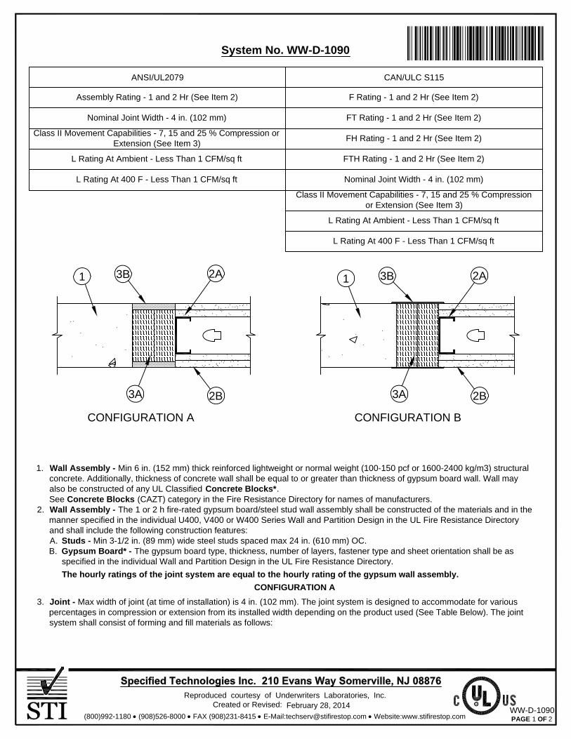
1. Wall Assembly - Min 6 in. (152 mm) thick reinforced lightweight or normal weight (100-150 pcf or 1600-2400 kg/m3) structuralconcrete. Additionally, thickness of concrete wall shall be equal to or greater than thickness of gypsum board wall. Wall mayalso be constructed of any UL Classified Concrete Blocks*.See Concrete Blocks (CAZT) category in the Fire Resistance Directory for names of manufacturers.
2. Wall Assembly - The 1 or 2 h fire-rated gypsum board/steel stud wall assembly shall be constructed of the materials and in themanner specified in the individual U400, V400 or W400 Series Wall and Partition Design in the UL Fire Resistance Directoryand shall include the following construction features:A. Studs - Min 3-1/2 in. (89 mm) wide steel studs spaced max 24 in. (610 mm) OC.B. Gypsum Board* - The gypsum board type, thickness, number of layers, fastener type and sheet orientation shall be as
specified in the individual Wall and Partition Design in the UL Fire Resistance Directory.
The hourly ratings of the joint system are equal to the hourly rating of the gypsum wall assembly.
CONFIGURATION A
3. Joint - Max width of joint (at time of installation) is 4 in. (102 mm). The joint system is designed to accommodate for variouspercentages in compression or extension from its installed width depending on the product used (See Table Below). The jointsystem shall consist of forming and fill materials as follows:
Created or Revised:Reproduced courtesy of Underwriters Laboratories, Inc.
PAGE OF(800)992-1180 (908)526-8000 FAX (908)231-8415 E-Mail:[email protected] Website:www.stifirestop.com
RFebruary 28, 2014
1 2
Ì80WWDÇ*zÈANÇ"<.ÇÎ
WW-D-1090
CONFIGURATION A CONFIGURATION B
3B1 2A
2B3A
3B1 2A
2B3A
System No. WW-D-1090
ANSI/UL2079
Assembly Rating - 1 and 2 Hr (See Item 2)
Nominal Joint Width - 4 in. (102 mm)
Class II Movement Capabilities - 7, 15 and 25 % Compression orExtension (See Item 3)
L Rating At Ambient - Less Than 1 CFM/sq ft
L Rating At 400 F - Less Than 1 CFM/sq ft
CAN/ULC S115
F Rating - 1 and 2 Hr (See Item 2)
FT Rating - 1 and 2 Hr (See Item 2)
FH Rating - 1 and 2 Hr (See Item 2)
FTH Rating - 1 and 2 Hr (See Item 2)
Nominal Joint Width - 4 in. (102 mm)
Class II Movement Capabilities - 7, 15 and 25 % Compressionor Extension (See Item 3)
L Rating At Ambient - Less Than 1 CFM/sq ft
L Rating At 400 F - Less Than 1 CFM/sq ft

A. Forming Material* - Min 4 pcf (64 kg/m3) mineral wool batt insulation installed in joint opening as a permanent form. Piecesof batt cut to min width of 4 in. (102 mm) and installed edge-first into joint opening, parallel with joint direction, such that battsections are compressed min 50 percent in thickness and such that the compressed batt sections are recessed from eachsurface of the wall to accommodate the required thickness of fill material (Item 3B). Adjoining lengths of batt to betightly-butted with butted seams spaced min 16 in. (406 mm) apart along the length of the joint.
IIG MINWOOL L L C - MinWool-1200 Safing
ROCK WOOL MANUFACTURING CO - Delta Board
ROCKWOOL MALAYSIA SDN BHD - SAFE
ROXUL INC - SAFE
THERMAFIBER INC - Type SAF
B. Fill, Void or Cavity Material* Sealant - Min 5/8 in. (16 mm) thickness of fill material installed on each side of the wallbetween the side of the gypsum board and the face of the concrete wall assembly, flush with each surface of the gypsumwall.
SPECIFIED TECHNOLOGIES INC - SpecSeal ES Sealant, SpecSeal LC150 Sealant, SpecSeal LCI Sealant and SpecSealSIL300 Series Sealant
The Movement Capabilities for each product are shown in following table:
CONFIGURATION B
3. Joint - Max width of joint (at time of installation) 4 in. (102 mm). The joint system is designed to accommodate a max 25%in compression or extension from its installed width. The joint system shall consist of forming and fill materials as follows:
A. Forming Material* - Sections of min 4 pcf (64 kg/m3) density mineral wool batt compressed 50 percent in thickness andinstalled cut edge first to completely fill the gap between the gypsum board and the concrete wall. The forming material shallbe installed flush with both surfaces of wall.
IIG MINWOOL L L C - MinWool-1200 Safing
ROCK WOOL MANUFACTURING CO - Delta Board
ROCKWOOL MALAYSIA SDN BHD - SAFE
ROXUL INC - SAFE
THERMAFIBER INC - Type SAF
B. Fill, Void or Cavity Material* - Sealant - Min 1/16 in. (1.6 mm) dry thickness (1/8 in. or 3.2 mm wet thickness) of fillmaterial spray applied over the forming material (Item 3A) on each side of the wall and overlap a min 1/2 in. (13 mm) ontogypsum board and concrete wall on both sides of the wall.
SPECIFIED TECHNOLOGIES INC - SpecSeal AS200 Elastomeric Spray
*Bearing the UL Classification Mark
ProductExtension
15ES Sealant
Compression
25
7
25
25
15
0
7
25
0
Movement Capabilities, %
ES Sealant
LC150 Sealant
LCI Sealant
SIL300 Sealant
Created or Revised:Reproduced courtesy of Underwriters Laboratories, Inc.
PAGE OF(800)992-1180 (908)526-8000 FAX (908)231-8415 E-Mail:[email protected] Website:www.stifirestop.com
RFebruary 28, 2014
2 2WW-D-1090

1. Wall Assembly - Min 4-1/2 in. (114 mm) thick reinforced lightweight or normal weight (100-150 pcf or 1600-2400 kg/m3)structural concrete.
2. Wall Assembly - The 1 or 2 hr fire-rated gypsum board/steel stud wall assembly shall be constructed of the materials and inthe manner specified in the individual U400, V400 or W400 Series Wall and Partition Design in the UL Fire ResistanceDirectory and shall include the following construction features:A. Steel Runners - Steel runners shall consist of min 25 gauge galv steel channels sized to accommodate steel studs (Item
2B). Steel runner to be provided with 1-1/4 in. (32 mm) flanges. Steel runner secured to concrete wall assembly with steelconcrete fasteners spaced 12 in. (305 mm) OC.
B. Studs - Steel studs to be min 3-1/2 in. (89 mm) wide. Studs cut 1/2 to 3/4 in. (13 to 19 mm) less in length than the assemblyheight with the bottom nesting in and resting on floor runner and with the top nesting in the ceiling runner withoutattachment. First stud adjacent to the concrete wall assembly to be located max 4 in. (102 mm) from the surface of theconcrete wall. Stud spacing not to exceed 24 in. (610 mm) OC.
C. Gypsum Board* - Gypsum board sheets installed to a min total thickness of 5/8 in. (16 mm) and 1-1/4 in. (32 mm) on eachside of wall for 1 and 2 hr fire rated assemblies, respectively. Wall to be constructed as specified in the individual Wall andPartition Design in the UL Fire Resistance Directory, except that a max 3/4 in. (19 mm) gap shall be maintained between theside of gypsum board and face of concrete wall assembly. The screws attaching the gypsum board to the first stud shall belocated 4 in. (102 mm) from face of concrete wall assembly. Gypsum board not attached to side runner.
The hourly ratings of the joint system are equal to the hourly rating of the gypsum wall assembly.
Created or Revised:Reproduced courtesy of Underwriters Laboratories, Inc.
PAGE OF(800)992-1180 (908)526-8000 FAX (908)231-8415 E-Mail:[email protected] Website:www.stifirestop.com
RFebruary 28, 2014
1 2
Ì86WWDÇ!#ÈANÇ"<.iÎ
WW-D-0103
1
2A2C
3C2B
1
2A2C
3B2B
3A
CONFIGURATION A CONFIGURATION B
System No. WW-D-0103
ANSI/UL2079
Assembly Rating - 1 and 2 Hr (See Item 2)
Nominal Joint Width - 3/4 in. (19 mm)
Class II Movement Capabilities - 7, 12.5, 25 and 40 %Compression or Extension (See Item 3)
L Rating At Ambient - Less Than 1 CFM/sq ft
L Rating At 400 F - Less Than 1 CFM/sq ft
CAN/ULC S115
F Rating - 1 and 2 Hr (See Item 2)
FT Rating - 1 and 2 Hr (See Item 2)
FH Rating - 1 and 2 Hr (See Item 2)
FTH Rating - 1 and 2 Hr (See Item 2)
Nominal Joint Width - 3/4 in. (19 mm)
Class II Movement Capabilities - 7, 12.5, 25 and 40 %Compression or Extension (See Item 3)
L Rating At Ambient - Less Than 1 CFM/sq ft
L Rating At 400 F - Less Than 1 CFM/sq ft

CONFIGURATION A
3. Joint - Max separation between the side of the gypsum board and the face of the concrete wall assembly is 3/4 in. (19 mm).The joint system is designed to accommodate for various percentages in compression or extension from its installed widthdepending on the product used (See Table Below). The joint system shall consist of forming and fill materials as follows:
A. Bond Breaker Tape - (Not shown) - Polyethylene tape supplied in rolls. Tape applied to flanges of steel runners (Item 2A)to prevent bonding of the sealant to steel runners. Bond breaker tape is optional when movement capability of the joint islimited to compression only.
B. Forming Material - (Optional, Not Shown) - In 2 hr fire rated wall assemblies, foam backer rod friction fit into joint openingand recessed minimum 5/8 in. (16 mm) from each surface of wall.
C. Fill, Void or Cavity Material* Sealant - Min 5/8 in. (16 mm) thickness of fill material installed on each side of the wallbetween the side of the gypsum board and the face of the concrete wall assembly, flush with each surface of the gypsumwall.
SPECIFIED TECHNOLOGIES INC - SpecSeal ES Sealant, SpecSeal LC150 Sealant, SpecSeal LCI Sealant and SpecSealSIL300 Series Sealant
The Movement Capabilities for each product are shown in following table:
CONFIGURATION B
3. Joint - Max separation between the side of the gypsum board and the face of the concrete wall assembly is 3/4 in. (19mm). The joint system is designed to accommodate a max 40% compression or extension from its installed width. Thejoint system shall consist of forming and fill materials as follows:
A. Forming Material* - Sections of min 4 pcf (64 kg/m3) density mineral wool batt compressed 50 percent in thickness andinstalled cut edge first to completely fill the gap between the gypsum board and the concrete wall. The forming material shallbe installed flush with both surfaces of wall.
IIG MINWOOL L L C - MinWool-1200 Safing
ROCK WOOL MANUFACTURING CO - Delta Board
ROCKWOOL MALAYSIA SDN BHD - SAFE
ROXUL INC - SAFE
THERMAFIBER INC - Type SAF
B. Fill, Void or Cavity Material* - Sealant - Min 1/16 in. (1.6 mm) dry thickness (1/8 in. or 3.2 mm wet thickness) of fillmaterial spray applied over the forming material (Item 3A) on each side of the wall and overlap a min 1/2 in. (13 mm) ontogypsum board and concrete wall on both sides of the wall.
SPECIFIED TECHNOLOGIES INC - SpecSeal AS200 Elastomeric Spray
*Bearing the UL Classification Mark
ProductExtension %
12.5ES Sealant
Compression %
25
7
25
12.5
12.5
0
7
12.5
0
Movement Capabilities
ES Sealant
LC150 Sealant
LCI Sealant
SIL300 Sealant
Created or Revised:Reproduced courtesy of Underwriters Laboratories, Inc.
PAGE OF(800)992-1180 (908)526-8000 FAX (908)231-8415 E-Mail:[email protected] Website:www.stifirestop.com
RFebruary 28, 2014
2 2WW-D-0103
25 0SIL300 Sealant

1Technical Service 1-800-992-1180www.stifirestop.com
• Water-Based Easy installation, cleanup, and disposal.
• Endothermic Fillers Absorb heat & release water.
• High Solids Formula No shrinkage!
• Paintable Paintable (when dry)
• Safe ... No Solvents! Non-Halogenated! Low VOC’s
• Red Color Easy identification and inspection.
• Installer Friendly Excellent caulking properties along with high build capabilities.
• Excellent Smoke Seal
• Flexible
SERIES LC ENDOTHERMIC SEALANT
PRODUCT DESCRIPTIONSpecSeal® Series LC Sealant is a latex-based, high solids firestop compound. This material, when properly installed, will effectively seal penetration openings and joints against the spread of fire, smoke, toxic gasses and water.
SpecSeal® Series LC Sealant is engineered to adhere well to virtually all construction surfaces and may be applied using a standard caulk gun or by troweling with a standard mason’s trowel or with a putty knife.
SpecSeal® Series LC Sealant dries without shrinking to form a flexible shield against the propagation of fire. Its premium latex binder system is totally resistant to water and will not re-emulsify after drying. SpecSeal® Series LC Sealant is non-halogenated, contains no asbestos, inorganic fibers or solvents.
SpecSeal® Series LC Sealant is the basis for systems that meet the exacting criteria of ASTM E1966 (UL2079) as well as the time-temperature requirements of ASTM E119. Tested systems will provide up to a 3 hour rating utilizing as little as 1/4" (6 mm) of sealant depth (1/2" (13 mm) for 4 hours).
PERFORMANCE
PHYSICAL PROPERTIES
Properties Series LC
Color Red
Odor Mild Latex
Density 11.4 lb./gal.
Solids Content 80% + 2%
pH 7.4-8.4
In Service Temperature ≤185˚ F (<85˚ C)
Storage Temperature 40˚F (4˚C) - 95˚F (35˚C)
Flame Spread 0*
Smoke Developed 10*
STC Rating (ASTM E90/ASTM C919) 61
VOC Content (EPA Method 24/ASTM D3960)
0.33 lb/gal.(40 g/L)
Shelf Life 2 Years
FEATURE BENEFIT
PRODUCT DATA SHEET
FILL, VOID OR CAVITY MATERIALS FOR USE IN JOINT SYSTEMS AND THROUGH-PENETRATION FIRESTOP
SYSTEMS. SEE UL DIRECTORY OF PRODUCTS CERTIFIED FOR CANADA AND UL FIRE RESISTANCE DIRECTORY.
3L73
SPECIFICATIONS
The firestopping sealant shall be a one-part, latex-based compound. The sealant shall dry to form a flexible non-shrinking penetration seal and shall be capable of allowing pipe movement and shall contain no solvents, water soluble fillers, or inorganic fibers. The sealant shall be thixotropic and shall be capable of caulking or troweling on to vertical surfaces or overhead. The sealant shall be UL Classified and tested to the requirements of ASTM E814 (UL1479).
SPECIFIED DIVISIONS
DIV. 7 07840 Through-Penetration Firestopping
DIV. 13 13900 Special Construction Fire Suppression & Supervisory
Systems
DIV. 15 15250 Mechanical Insulation – Fire Protection
DIV. 16 16050 Basic Electrical Materials & Methods
APPLICATIONSSpecSeal® Series LC Sealant is designed primarily for sealing construction joints and gaps as well as penetrations for noncombustible penetrants. SpecSeal Series LC has been tested and approved for single metallic pipe penetrations up to 24" (610 mm) as well as multiple penetrants through both masonry and gypsum wallboard constructions. Additional systems have been tested for steel sleeved penetrations as well as some common electrical and communications cable penetrations and joint penetrations. See STI’s Product & Application Guide as well as the UL Fire Resistance Directory for complete listings.
STI Product Data Sheet • Series LC Endothermic Sealant • FOD-5130 03/2010
*ASTM E84 (UL723) @ 14% Surface coverage. (Modified test for sealants and caulks.)
2 Technical Service 1-800-992-1180www.stifirestop.com
INSTALLATION INSTRUCTIONSGENERAL: Areas to be protected must be clean and free of oil, loose dirt, rust or scale. Installation temperatures must be between 35°F (2°C) and 100°F (38°C). Allow product to dry a minimum of 24 hours before exposure to moisture.
SYSTEM SELECTION: Consult UL® Fire Resistance Directory, STI Product & Application Guide, or drawings provided by the manufacturer for specific details concerning installation design and requirements.
FORMING: Some installations may require forming as either an integral part of the system or as an option to facilitate installation. In systems where forming is required, mineral wool batting (3" (76 mm) nom. thickness, min. 4 lb./cu. ft. 64 kg/m3 density) is recommended. Mineral wool is to be highly compressed and friction fitted into the opening. Position forming or packing material to allow for the proper depth of fill material.
INSTALLATION OF FILL MATERIAL: SpecSeal® Series LC sealant may be installed by caulking using a standard caulking gun or from bulk containers using a bulk loading caulk gun, or by manually troweling using a mason’s trowel or putty knife. If the sealant tends to pull back from a surface, clean the surface with a damp rag or sponge and reapply. Install sealant to required depth. Work sealant into all areas exercising care to eliminate voids or seams. The surface of the sealant can be smoothed using a putty knife dipped in water. Adding water to the sealant itself is not recommended. Sealant (when dry) may be sanded and painted using most non-solvent based paints. In gypsum wallboard penetrations, crown sealant a minimum of 1/4" (6 mm) from penetrant to wallboard surface at a point approx. 1/2" (13 mm) or more from opening.
COVER PLATE: In some designs a galvanized steel cover plate (28 gauge) may be used to upgrade the fire resistance rating to 4 hours. Consult STI Product and Application Guide for dimensional and fastening requirements.
LIMITATIONS: SpecSeal® Series LC Sealant is water-based and cures through the evaporation of water. Low temperatures as well as high humidity may retard drying. Non-porous or impermeable backing materials, plates or coatings may retard the drying process. Do not paint or seal in any way that prevents contact with air until sealant has dried through completely.
MAINTENANCEInspection: Installations should be inspected periodically for subsequent damage. Any damage should be repaired using SpecSeal® Series LC Sealant as per the original approved design. Retrofit: When adding or removing penetrants, care should be taken to minimize damage to the seal. Reseal using SpecSeal® Series LC Sealant as per the approved design. NOTE: New penetrants of a different nature than the original design may require a totally new firestop design or extensive modifications to the existing design. Reseal openings as per the requirements of the modified design.
TECHNICAL SERVICESpecified Technologies Inc. provides toll free technical support to assist in product selection and appropriate installation design. UL Systems, Material Safety Data Sheets and other technical information is available at the Technical Library at www.stifirestop.com.
PRECAUTIONARY INFORMATIONConsult Material Safety Data Sheet for additional information on the safe handling and disposal of this material. Wash areas of skin contact with soap and water. Avoid contact with eyes. The use of an OSHA or NIOSH approved mask for dust and mist environment is recommended. Apply in areas with ade-quate ventilation.
CAUTION: COATING IS CONDUCTIVE UNTIL DRY. DO NOT APPLY TO OR IN THE PRESENCE OF ENERGIZED ELECTRICAL CONDUCTORS.
AVAILABILITYSpecSeal® Series LC Sealant is available from authorized distributors worldwide. Consult factory for names and locations of the nearest sales representa-tives or distributors.
Cat. No. Description Packaging Size
LC150 Endothermic Firestop Sealant 10.1 oz. Tube 18.2 cu in. (300 ml)
LC120 Endothermic Firestop Sealant 20 oz. Sausage 36 cu. in. (592 ml)
LC129 Endothermic Firestop Sealant 29 oz. Tube 52 cu. in. (858 ml)
LC155 Endothermic Firestop Sealant 5 gal. Pail 1,155 cu. in. (19 liters)
IMPORTANT NOTICE: All statements, technical information, and recommendations contained herein are based upon testing believed to be reliable, but the accuracy and completeness thereof is not guaranteed.
WARRANTYSpecified Technologies Inc. manufactures its goods in a manner to be free of defects. Should any defect occur in its goods (within one year), Specified Technologies Inc., upon prompt notification, will at its option, exchange or repair the goods or refund the purchase price.
LIMITATIONS AND EXCLUSIONS: THIS WARRANTY IS IN LIEU OF ALL OTHER REPRESENTATIONS EXPRESSED OR IMPLIED (INCLUDING THE IMPLIED WARRANTIES OF MERCHANTABILITY OR FITNESS FOR USE) AND UNDER NO CIRCUMSTANCES SHALL SPECIFIED TECHNOLOGIES INC. BE RESPONSIBLE FOR ANY INCIDENTAL OR CONSEQUENTIAL PROPERTY DAMAGE OR LOSSES. PRIOR TO USE, THE USER SHALL DETERMINE THE SUITABILITY OF THE PRODUCT FOR ITS INTENDED USE, AND THE USER ASSUMES ALL RISKS AND LIABILITY FOR SUBSEQUENT USE.No statement or recommendation not contained herein shall have any force or effect unless in an agreement signed by officers of seller and manufacturer.
MADE IN THE USA – COPYRIGHT © 2008 SPECIFIED TECHNOLOGIES, INC.
210 Evans Way • Somerville, NJ 08876 | Toll Free: 800-992-1180 • F: 908.526.9623
CITY OF NEW YORK MEA 129-96-M
STI Product Data Sheet • Series LC Endothermic Sealant • FOD-5130 03/2010
Page 1 of 3 MSDS - SpecSeal® SERIES LC Sealant FOD-5004
Material Safety Data Sheet ___________________________________________________
22-JULY-2013
SpecSeal® SERIES LC SEALANT
CHEMICAL PRODUCT/COMPANY IDENTIFICATION
Material Identification PRODUCT NAME....................SpecSeal® LC Sealant
CHEMICAL FAMILY..................Mixture
Company Identification
MANUFACTURER/DISTRIBUTOR Specified Technologies Inc. 210 Evans Way Somerville, NJ 08876
PHONE NUMBERS
Product Information : 1-908-526-8000 Emergency : 1-800-255-3924 HAZARDS IDENTIFICATION
**********EMERGENCY OVERVIEW*********** Possible skin and eye irritant. Paste. ****************************************************
Potential Health Effects:
EYE: Contact may cause irritation.
SKIN: Contact may cause irritation.
INGESTION: Relatively non-toxic.
INHALATION: Irritation of the nose, throat, and lungs may result from over-exposure to vapors or mist.
CHRONIC (CANCER) INFORMATION: Not classified as carcinogenic.
LONG TERM TOXIC EFFECTS: None known.
COMPOSITION/INFORMATION ON INGREDIENTS Proprietary mixture containing in part:
INGREDIENT NAME CAS NUMBER ACRYLIC POLYMER 67967-61-7 ALUMINO SILICATE MICROSPHERES NA CACIUM CARBONATE 1317-65-3 BUTYLATED TRIPHENYL PHOSPHATE NA

FIRST AID MEASURES
First Aid INHALATION: Remove to fresh air. SKIN CONTACT: Wash thoroughly. EYE CONTACT: Irrigate eyes with running water for at least 15 minutes. Get medical attention if irritation develops. INGESTION: None applicable.
FIRE FIGHTING MEASURES
Not a fire hazard.
EXTINGUISHING MEDIA .............................................Dry Chemical; Carbon Dioxide; Foam; Water spray for large fires.
SPECIAL FIRE FIGHTING PROCEDURES: ................As for surrounding fire.
ACCIDENTAL RELEASE MEASURES
Safeguards (Personnel) NOTE: Review FIRE FIGHTING MEASURES and HANDLING (PERSONNEL) sections before proceeding with clean-up. Use appropriate PERSONAL PROTECTIVE EQUIPMENT during clean-up
HANDLING AND STORAGE
Store under ambient conditions. No special handling required.
EXPOSURE CONTROLS/PERSONAL PROTECTION
EYE PROTECTION REQUIREMENTS: .......................Safety glasses/goggles.SKIN PROTECTION REQUIREMENTS: .....................Gloves.RESPIRATOR REQUIREMENTS: ...............................None.VENTILATION REQUIREMENTS: ............................... If needed, use local exhaust ventilation to keep airborne concentrations below the TLV. Exposure Guidelines Exposure Limits PEL(OSHA) : Particulates (Not Otherwise Classified) 15 mg/m3, 8 Hr. TWA, total dust 5 mg/m3, 8 Hr. TWA, respirable dust TLV(ACGIH): None Established PHYSICAL AND CHEMICAL PROPERTIES
PHYSICAL FORM .................................................... Paste with minimal odorSPECIFIC GRAVITY ................................................ 1.24PERCENT VOLATILES ............................................ 20 +/- 2EVAPORATION RATE .............................................. >1BOILING POINT ....................................................... 100 deg. CSOLUBILITY IN WATER ........................................... Infinitely dilutableCARB VOC (Calculated)……………………… 0.46 Wt. % SCAQMD VOC (US EPA Method 24)………….57 Grams/Liter
STABILITY AND REACTIVITY
STABILITY: ............................................................... This is a stable material.CONDITIONS TO AVOID ......................................... Storage >55 deg. CHAZARDOUS POLYMERIZATION: .......................... Will not occur.INCOMPATIBILITIES:…………………………….........None special.
TOXICOLOGICAL INFORMATION Mixture not tested but based on components:May be irritating to skin and eyes and may aggravate existing skin and eye conditions.None of the components are listed as carcinogens.
Page 2 of 3 MSDS - SpecSeal® SERIES LC Sealant FOD-5004

Page 3 of 3 MSDS - SpecSeal® SERIES LC Sealant FOD-5004
ECOLOGICAL INFORMATION
No data.
DISPOSAL CONSIDERATIONS Waste Disposal: Treatment, storage, transportation, and disposal must be in accordance with applicable Federal, State/Provincial, and Local regulations.
TRANSPORTATION INFORMATION
DOT – not regulated.
REGULATORY INFORMATION U.S. Federal Regulations TSCA Inventory Status: Reported/Included.Section 313 Supplier Notifications. This product contains no toxic chemicals subject to the reporting requirements of Section 313 of the Emergency Planning and Community Right-To-Know Act of 1986 and of 40 CFR 372:
OTHER INFORMATION NPCA-HMIS Rating Health : 1 Flammability : 0 Reactivity : 0Personal Protection rating to be supplied by user depending on use conditions.
STATE RIGHT-TO-KNOW LAWS No substances on the state hazardous substances list, for the states indicated below, are used in the manufacture of products on this Material Safety Data Sheet, with the exceptions indicated. While we do not specifically analyze these products, or the raw materials used in their manufacture, for substances on various state hazardous substances lists, to the best of our knowledge the products on this Material Safety Data Sheet contain no such substances except for those specifically listed below:
SUBSTANCES ON THE NEW JERSEY WORKPLACE HAZARDOUS SUBSTANCE LIST PRESENT AT A CONCENTRATION OF 1% OR MORE (0.1% FOR SUBSTANCES IDENTIFIED AS CARCINOGENS, MUTAGENS OR TERATOGENS): GRAPHITE WARNING: SUBSTANCES KNOWN TO THE STATE OF CALIFORNIA TO CAUSE CANCER: Possible traces of formaldehyde, ethyl acrylate, acetaldehyde,and acrylonitrile. WARNING: SUBSTANCES KNOWN TO THE STATE OF CALIFORNIA TO CAUSE BIRTH DEFECTS OR OTHER REPRODUCTIVE HARM: None known.------------------------------------------------------------------This information relates to the specific material designated and may not be valid for such material used in combination with any other materials or in any process. Such information is to the best of our knowledge and belief accurate and reliable as of the data compiled. However, no representation, warranty, or guarantee is made as to its accuracy, reliability or completeness. It is the user’s responsibility to satisfy himself as to the suitability and completeness of such information for his own particular use. We do not accept liability for any loss or damage that may occur form the use of this information.
Responsibility for MSDS : Specified Technologies Inc.210 Evans WaySomerville, NJ 08876