Fire Tests of Rigid Plastic Ventilation Ducts · Standardized small-scale flammability test ......
21
Bureau of Mines Report of Investigations/1987 Fire Tests of Rigid Plastic Ventilation Ducts By F. J. Perzak. C. P. Lazzara. and T. A. Kubala UNITED STATES DEPARTMENT OF THE INTERIOR
Transcript of Fire Tests of Rigid Plastic Ventilation Ducts · Standardized small-scale flammability test ......

Bureau of Mines Report of Investigations/1987
Fire Tests of Rigid Plastic Ventilation Ducts
By F. J. Perzak. C. P. Lazzara. and T. A. Kubala
UNITED STATES DEPARTMENT OF THE INTERIOR

?
Report of Investigations 9085
Fire Tests of Rigid Plastic Ventilation Ducts
By F. J. Perzak, C. P. Lazzara, and T. A. Kubala
UNITED STATES DEPARTMENT OF THE INTERIOR Donald Paul Hodel, Secretary
BUREAU OF MINES Robert C. Horton, Director

Library of Congress Cataloging in Publication Data:
Perzak, F. J. (Frank J.) Fire tests of rigid plastic ventilation ducts.
(Report of investigations/United States Department of the Interior, Bureau of Mines; 9085)
Bibliography: p. 16.
Supt. of Docs. no.: I 28.23: 9085.
1. Glass reinforced plastics-Fire-testing. 2. Air ducts-Fire-testing. I. Lazzara , Charles P. II. Kubala, T. A. (Theodore A.l. III. Title. IV. Series: Report of investigations (United States. Bureau of Mines); 9085.
TN23 .U43 [TH9446.5.P45] 622 s [628.9'22] 86-607914
CONTENTS
Abstract .................................•..................................... Introduction ..............................•.........................•.......... Acknowledgments •. .. . .•......................................................... Te s t sa mp 1 e s ••••••••••••.•..•.•••••..••••••••••.•••••.•.•..••.•••••••••.••••••• Experimental fire tests and results .••••••••••••••••••••••••.••••••••••..••••••
ASTM fire tests ••.•..••••••••••••••.•••••••••••••••••••••••••••••••••.••••••• Standardized small-scale flammability test (S 3FT) •••••.••••••••••••.•••••••••
Description ...........................•.................................... Resul ts ..........................................................•...•....•
Large-scale vertical fire test •••.•••••••••••••.••••.•••••••••••••••••••••••• Full-scale in-mine fire test •••••••••.•••••••••••••••••••••••••.•••••••.•••••
1 2 2 3 3 3 4 4 4 6 7
Description ...............................•................................ 7 Results.................................................................... 8
Conclusions and recommendations................................................ 15 References..................................................................... 16
ILLUSTRATIONS
1. Ignition of 16-in-diam FRP duct in the standardized small-scale flam-mability test apparatus.................................................. 5
2. Schematic view of setup for large-scale vertical fire test of ventila-tion duct................................................................ 6
3. Temperatures inside duct C during vertical fire test...................... 7 4. Vertical fire test of duct C.............................................. 8 5. Vertical fire test of duct A (right side) and duct C.. . .................. . 9 6. Vertical fire test of duct F.............................................. 10 7. Test arrangement for full-scale in-mine fire tests of ventilation ducts... 11 8. In-mine fire test of duct D............................................... 11 9. Charred fiberglass carcass of duct F after in-mine fire test.............. 12
10. Temperature-time profiles of duct B during in-mine fire test.............. 12 11. In-mine fire test of 20-in-diam ventilation duct.......................... 13 12. Flame position versus time for in-mine fire tests of ducts that failed.... 14
TABLES
1. Description of plastic ventilation ducts.................................. 3 2. Results of laboratory-scale ASTM tests................................... 4 3. Results of standarized small-scale flammability test (S3FT)............... 5 4. Vertical fire test sequence of events for duct F.......................... 10 5. Results of full-scale in-mine fire test................................... 14

UNIT OF MEASURE ABBREVIATIONS USED IN THIS REPORT
Btu/lb British thermal unit per pound lb pound
Btu/min British thermal unit per minute min minute
°c degree Celsius mL mUli liter
ft foot pct percent
ft/min foot per minute pt pint
in inch qt quart
kW kilowatt s second
L liter wt weight

FIRE TESTS OF RIGID PLASTIC VENTILATION DUCTS
By F. J. Perzak,l C. P. Lazzara,2 and T. A. Kubala'
ABSTRACT
The Bureau of Mines conducted a flammability study of plastic ventilation ducts. Six rigid 16-in-diam fiberglass-reinforced plastic ducts from five manufacturers were examined using laboratory-scale, largescale, and full-scale fire tests. The laboratory-scale tests included the American Society for Testing and Materials E162 radiant panel test, the E2863 oxygen index test, and the standardized small-scale flammability test (S 3FT) developed by the Mine Safety and Health Administration (MSHA), U.S. Department of Labor, and replicated by the Bureau of Mines. Ten-foot lengths of the same ducts were also subjected to a large-scale vertical fire test, and 20- to 30-ft lengths were tested in a full-scale in-mine fire test at the Bureau's Lake Lynn Laboratory mine.
The data from the laboratory-scale radiant panel test and oxygen index test indicated that the ducts were fire-resistant , However, five of the six ducts failed the S3FT and vertical fire tests, and four of the ducts failed the full-scale in-mine tests with flame propagation rates that ranged from 3 to 10 ft/min. The results indicate the need for improved fire-resistant plastic ducts. The good agreement between the S3FT results and the vertical and full-scale tests show that the S3FT provides a good indication of the flammability of fiberglass-reinforced plastic ducting under realistic fire conditions.
1Research chemist. 2Supervisory research chemist. 3Research physicist. Pittsburgh Research Center, Bureau of Mines, Pittsburgh, PA.

2
INTRODUCTION
-reinforced tic ) ducts or tubes are used in mines for ventilation purposes where corrosion res is
mechanical strength, and cost are considerations. A fire in
FRP ducting, however, with the attendant smoke and gaseous can be a severe hazard to personnel in under
mines or other confined areas. A fire in a duct can feed back to itself well over 50 pct of the combustion heat as demonstrated by fires in wood-lined ducts (l)4 and is thus more severe than a fire on a flat surface. Nevertheless, FRP duct is current used to line chimneys as stack liners for indus-trial 3, and in vertical shafts (i). FRP ts 3 ft in diam and 30 ft long tested in the ver-tical Factory Mutual Re-search combustion over the full occurred after 1 min of exposure to a moderate heptane fire under the duct (~). Al mine fires FRP ducts have been few, two fatalities occurred in 1971 in a metal mine when ducting was
a cutting torch and about 400 ft burned (~).
resist a plastic and usually
material to flame
estimated by tests. However,
these tests consider the end use material or provide a realistic
few of of the
.::Innr'",i sal full-of the flammability behavior under
scale fire conditions. Federal tions for ventilation 6 materials approved
mines to have a flame index of 25 or less, based on the American Society for Tes Materials (ASTM) E162 radiant test or E84 tunnel test The "25 or less," value was previously thought "to a reasonably safe condition" for ducts in coal mines. There are no Federal fire-resistance standards for ventilation tubing in metal and nonmetal mines. A voluntary pro-cedure for of FRP ventilation tubing underground coal mines re-cently by MSHA includes a stan-dardized small-scale fire test In this test, 4-ft-long 16-in-diam duct are ignited a gas burner in a horizontal tunnel, and the time for flame extinguishment and the extent of
were determined. In this study, 16-in-diam FRP ducts
from five manufacturers were ected to arqe-s:cRlle, and fulllaboratory-scale,
scale fire tests to evaluate their fire resistance and to compare test results. The laboratory-scale tests included the ASTM E162 radiant test (9), the E2863 oxygen index test (10), and the S3FT developed by MSHA. -rhe MSHA Approval and Certification Center also tested the ducts in its S appartus. Ten-foot of the same ducts were subjected to ~ verti-cal fire test, and 20- to 30-ft duct samples were tested in a full-scale in-mine fire test at the Bureau's Lake Lynn Laboratory mine 11. The test and results are in this report.
ACKNOWLEDGMENTS
The authors wish to the contributions of personnel from the MSHA
fer to items in the list of references at the end of this report.
Industrial the ASTM E162 the MSHA
ter for S
Division for conduct radiant panel tests and and Certification Cen
the tests in the MSHA

3
TEST SAMPLES
Fiberglass-reinforced plastic ventilation tubing is routinely manufactured in 10- and 20-ft lengths with diameters ranging from 12 to 60 in. Oval configurations are also available. For this study, a sufficient number of 16-in-diam duct 10 ft long was purchased from five manufacturers so that all the fire tests could be conducted with the same sample batch. The 16-in-diam ducting is a common size used in mines. Table 1 gives a description of the tubing. In two of the in-mine tests, 12-in-diam and 20-in-diam ducting from the same source as duct samples C and D were also used for comparison.
All the ducts were accepted by MSHA for use in underground coal mines based on a
flame spread index of 25 or less by the ASTM E162 test method. Sample A had heavier and thicker walls than did the other ducts and was manufactured with a highly fire-resistant resin containing a high loading of aluminum trihydrate. The major fire retardant in the other ducts was approximately 1 to 3 wt pct antimony oxide. The heating values are an indication of the maximum combustible content of the duct and vary with the percentage of the components, such as the ratio of fiberglass to plastic resin. Ducts C and D were different batches from the same source; duct D contained a higher concentration of fire retardant.
EXPERIMENTAL FIRE TESTS AND RESULTS
ASTM FIRE TESTS
The ASTM laboratory-scale tests were the ASTM E162 radiant panel (9) and the E2863 oxygen index (lQ). In this study, the tests were applied to composite plastic materials; i.e., rigid ducts. These tests provide an estimate of the response
of the duct sample to heat and flame under controlled conditions and are not recommended to assess the fire hazards of a material under realistic fire conditions.
The samples for the ASTM tests were cut from 16-in-diam ducts. The samples for
TABLE 1. - Description of l6-in-diameter, 10-ft-long ducts
Duct Generic description Total weight, Wall thickness, Heating value, 2
Ib in Btu/lb A ••• Plastic resin 1 •••••••• } Glass fiber filler •••• 58 5/32 4,000
Aluminum trihydrate ••• B ••• Plastic resin .........
} Fiberglass ribbon ••••• 32 1/16 3,450 Aluminum trihydrate ••. Antimony oxide ••••••••
C ••• Plastic resin ......... } Fiberglass ribbon ••••• 37 3/32 4,530 Antimony oxide •••••• o.
n ••• • •• do ••••••••••••••••• 37 3/32 3,930 E ••• • •• do ••••••••••••••••• 36 3/32 2,920 F ••• • •• do ••••••••••••••••• 41 1/8 3,600
1 The plastic resin is a thermosetting polyester resin. 2Determined by ASTM D2015, Gross Calorific Value of Solid Fuel by the
Adiabatic Bomb Calorimeter (~).

4
the oxygen index test were the thickness of the duct wall and 0.5 in wide 6 in
The samples for the radiant panel test were 6 in wide by 18 in long. Any effects due to the slight curvature of the were
The oxygen index and radiant results for the duct are table 2. The limiting oxygen index is the lowest value of the ratio of oxygen to oxygen nitrogen that will candle-like combustion of the sample: The the value, the
the fire resistance of the duct sample. The individual values of the limiting oxygen values from 27.1 to 44.7 and were within ±O.S for each sample. The average value for all the samples is 37, which s that the material contains fire retardants.
The flame spread index from the radiant panel test is calculated from the flame
rate and heat evolution factor. A low flame index a high fire resistance. The values range from 5±3 to 42±20, with an average of 14.7 for all the The variances in the indices are due to difficulties in determin-ing read rate and the heat evolution factor for these inhomogenous composite materials. A flame spread index of 25 or less is red for the ducts to be permitted in underground coal mines. All the ducts duct C were well within this rement level.
The fire-resistance rankings of the duct based on their limit ox-
indices are in ex-The rank-
was 0.96, where 1.0 a
no correlation. correlation and 0.0
TABLE 2. - Results of ASTM tests
Duct Limiting oxygen index
A ....... 44.7 B ....... 33.0 c .•...• 27.1 D •••••• 36.3 E •••••• 37.9 F •••••• 43.4
cale
Flame ld index 5± 3
15± 5 42±20
9± 6 1I± 9
7±10
STANDARDIZED SMALL-SCALE FLAMMABILITY TEST (
The S3FT apparatus consists of sulated ventilated tunnel, 5 ft 3.5 ft and 2.5 ft wide. A
an inlong by
16-in-diam duct without flaired ends or is suspended hori
the center of the tunnel. source is a 1 et gas delivers 26 kW over a burner that
4-in-wide by 1 (l flame). The burner is the lower edge of the duct sample so that two-thirds of the burner flame is under the tubing and the one-third of the flame is allowed to lick into the inside of the The burner flame is held in contact with the duct for exactly 1 min. The tunnel ventilation flow is controlled to 0 or 125 ft/min air velocity over the suspended duct sample. Figure 1 shows the ignition of a 16-in-diam duct sample. The insert shows the -duct flame 2 min after the removal of the burner.
A total of six duct sections are tested in two groups of 3, at 0 and 125 ft airflow. A sample fails if (1) flame
4 ft (total ) in any or (2) the average time durburning duct measured after
burner removal exceeds 1 min at either air velocity, or ) the time duration of the duct after burner removal exceeds 2 min for anyone of the six sam-
tested.
Results
The same five FRP ducts were subjected to the S3FT by the Bureau and by'S Approval and Certification Center to compare the reproducibility of the results between laboratories. A sixth duct, sam-
C, was tested MSHA. Table 3 the average flame duration after
removal of the burner for each sample and whether the duct or failed. For some ducts, a complete series of six tests was not completed when failure was assured.

FIGURE 1.-lgnitlon of 16-in-diam FRP duct In the standardized small-scale flammability test apparatus. Insert shows flaming duct 2 min after burner removal.
TABLE 3. - Standardized small-scale flammability test (S3FT)
Average Duct MSHA flame time,
min A •••••••••• 10.02 B •••••••••• 2>3 e .....•.... >3 D •••••••••• 2>3 E •••••••••• 32.8 ±0.9 F •••••••••• 37 ±4
NA Not available. ISample self-extinguished 2Sample was extinguished 3
have burned the full 4 ft in 3Samp l e self-extinguished.
the standard deviation using
Average Bureau flame time, Fail or pass
min 10.03 Pass.
2>3 Fail. NA Do.
2>3 Do. 34 ±O.S Do.
2>3 Do.
within 2 s after burner removal. min after burner removal and would most cases.
The value following the ± sign is all 6 tests at both flows.
5

6
Only duct A passed the S3FT by selfextinguishing as soon as the burner was removed. Ducts E and F self-extinguished; however, their average time for "after burning" exceeded 1 min and they failed by criteria 2 and 3. Ducts B, C, and D failed by all three criteria and were purposely extinguished ~ecau§e
of excessive smoking. ~h~y,wo~ld have burned their full length if allowed to continue. The test results between the Bureau and MSHA laboratories were in excellent agreement.
LARGE-SCALE VERTICAL FIRE TEST
The large-scale vertical fire test consisted of a 16-in-diam, 10-ft-long duct suspended vertically over a nominal 22-in-diam pool fire of 1.3 pt (600 mL) of heptane. In a few tests, the duct was instrumented with 20 gage type K thermocouples with their beads inserted about 2 in from the inside wall of the duct. The pool fire burned for about 1.3 min. Blank trials using steel ducts gave temperatures at the top of the duct as high as 1,000° C in about 40 s. Figure 2 shows a schematic view of the test setup for a 10-ft-section of ventilation duct. A duct failed the vertical test if it was consumed by flames leaving only a charred fiberglass carcass.
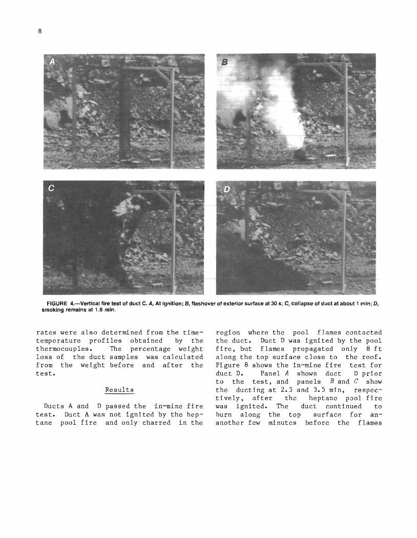
Figure 3 shows the temperature profiles at three locations for duct C. The data record starts at zero time; however, the igniter began at about 0.4 min. The sudden drop in temperature about 0.8 min is probably due to the flame bursting through the walls. The heptane igniter was out at about 1 min. Figure 4 shows the vertical fire test for duct C. Panel A shows the duct at ignition. After 30 s, the exterior surface is engulfed in flames (panel B) and at about 1 min (panel C) the duct collapses leaving fiberglass ribbons (panel D). Approximately 22 pct of the weight of the original duct was consumed in about 2 min or less, with the generation of large quantities of black, acrid smoke. Several tests were made with duct C at a 45° angle with similar results as the vertical test. The combustible products were not analyzed.
16-in I f---d-ia-m---l HEIGHT, in
r-----;-, 120
114
----- - T her mocouple
Ventilation duct
66 BLOWUP
Thermocouple
'--+-----1~~ ~
-I----,.--------:I-~" 21.5-in-diam , Ld
metal tray
FIGURE 2.-Schematlc view of setup for large-scale vertical fire test of ventilation duct.
Ducts A and C were tested simultaneously in the vertical configuration. Figure 5 shows the vertical fire test for ducts A and C. Panel A shows the experimental setup before ignition with duct C on the left side. Panels Band C show the ducts at 76 sand 90 s, respectively, after ignition. Duct A on the right was virtually undamaged, but duct C was consumed by the flames. Ducts B, D, E, and F behaved similarly to duct C and failed the vertical fire test. Duct A was the only one that passed the test. For the five ducts that burned, weight losses varied from 22 pct for duct C to 34 pct for duct
1,000 ,-----,------.------,---.-----.-----,
900 KEY Thermocouple positions
~ 18 in 800 -- 66 in
---6-114 in
700 u o
W ~ 600
~ 0:: W 500 a. ::E w l-IU :::::> o
2 3 TIME, min
FIGURE 3.-Temperatures Inside duct C during vertical fire test. Thermocouple heights measured from bottom.
E. The weight loss for duct A was negligible and this duct was retested many times with little damage.
The results of a large-scale vertical fire test of duct F are described in detail in table 4 where the temperatures at a position 6 in from the top inside the duct and comments of significant events are given. Figure 6 shows the vertical fire test of duct F.
FULL-SCALE IN-MINE FIRE TESTS
Description
The in-mine duct fire designed to provide data on bility behavior of the ducts scale conditions. The tests formed in a 7-ft-high by
tests were the flammaunder full -
were per-19-ft-wide
7
horizontal entry in the Lake Lynn Laboratory mine (11). The air ventilation in the entry was approximately 190 ft/min. Two or three 10-ft sections of the duct were suspended horizontally to form a nominal 20-ft or 30-ft run. When a 20-ft run of a particular duct was tested, a 10-ft section of highly fire resistant duct A was attached on the end to obtain a total 30 ft length. The ducts were supported every 5 ft by a looped chain attached to an overhead chain. The outer surface of the first duct was positioned approximately 1 ft from a metal shield protecting the mine roof and rib in the ignition area. The distance of the following duct sections from the rock mine ribs and roof ranged from 1.25 to 2 ft. The suspended duct run was instrumented with type K thermocouples. The thermocouples were positioned at 2-ft intervals, starting at the upstream edge of the first duct, with their measuring junctions just inside the duct walls. The thermocouples were connected to a data acquisition system that recorded the thermocouple readings every 6 s during a test. Video recordings e nd photographs were made for most of the tests by cameras located near the floor about 25 ft upstream of the ignition region.
The ignition source was a 22-in-diam tray fire of 2.1 qt (2 L) of heptane. The l.s-in-deep tray was supported by a metal stand and contained a layer of water on which the heptane was floated. The heptane pool was positioned 4 in below the upstream edge of the duct run with the end of the duct over the center of the pool. In this position, the pool flames impinged on the outer and inner duct surfaces. The heptane pool was remotely ignited by an electric match and burned about 3.5 min with a heat output of about 16,300 Btu/min. Figure 7 shows the test arrangement for the in-mine tests.
For this study, a duct was considered to fail the in-mine test if it ignited and flames propagated to the end of the second duct section, a distance of about 20 ft. The extent of flame propagation was determined by the thermocouples, video recordings, and examination of the ducting after the test. Flame spread
8
FIGURE 4.-Vertlcal fire test of duct C. A, At ignition; B, flashover of exterior surface at 30 s; C, collapse of duct at about 1 min; D, smoking remains at 1.8 min.
rates were also determined from the timetemperature profiles obtained by the thermocouples. The percentage weight loss of the duct samples was calculated from the weight before and after the test.
Results
Ducts A and D passed the in-mine fire test. Duct A was not ignited by the heptane pool fire and only' charred in the
region where the pool flames contacted the duct. Duct D was ignited by the pool fire, but flames propagated only 8 ft along the top surface close to the roof. Figure 8 shows the in-mine fire test for duct D. Panel A shows duct D prior to the test, and panels Band C show the ducting at 2.5 and 3.5 min, respectively, after the heptane pool fire was ignited. The duct continued to burn along the top surface for ananother few minutes before the flames

FIGURE 5.-Vertlcal fire test of duct A (right side) and duct C. A, Before ignition; 8, 76 s after Ignition; C, 90 s after Ignition; D, after test.
9

10
Time, min:s 0:00
:34 :38 :42 :46 :57
1:07 1:16 1:21 1:48 2:49 3:28 4:03
TABLE 4. - Vertical fire test sequence of events for duct F
Temperature, 1
°c 20
470 500 570 600 942 985
1,010 860 670 320 210
70
Event
Tray fire ignition (figure 6, panel A). Black smoke from top of duct. Flame 4 ft high inside duct. White smoke 2 ft up from bottom on outside of duct. Heavy black smoke from top of duct. Flame in smoke at top of duct (figure 6, panel B). Duct sways and sags, smoke and flame from top. Continuous flame from top of duct. Tray fire out. Entire duct on fire. Heavy black smoke (figure 6, panel C). Duct burning at top 2 ft and bottom 1 ft. Flame at top rim, and 2 ft down from top. No flame visible (figure 6, panel D).
1Thermocouple located inside duct, 6 in from top.
FIGURE 6.-Vertlcal fire test of duct F. A, At ignition; B, 57 s after Ignition; C, 108 s after Ignition; D, after 4 min.
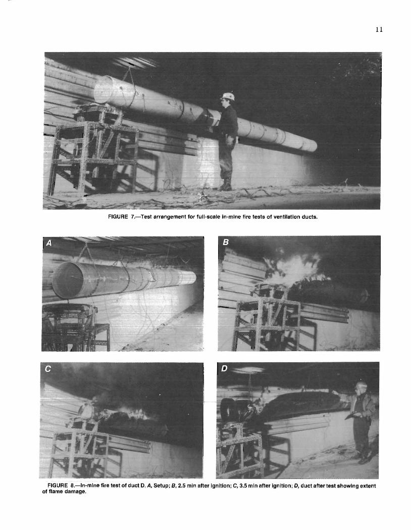
FIGURE 7.-Test arrangement for full-scale In-mine fire tests of ventilation ducts.
FIGURE 8.-ln-mine fire test of duct D. A, Setup; 8,2.5 min after Ignition; C, 3.5 min after Ignition; D, duct after test showing extent of flame damage.
11

12
self-extinguished. Panel D shows the ducting after the test.
The four remaining 16-in-diam duct samples, B, C, E, and F, all failed the in-mine test due to the propagation of flames over the entire sample length. The flame spread rates ranged from 3.1 to 9.8 ft/min. During the tests, large quantities of smoke were produced and carried downstream by the ventilation flow. The remains consisted of a charred fiberglass carcass, as shown in figure 9 for duct F. Weight losses due to the burning of the combustibles in the duct ranged from 10 to 40 pct and were mainly dependent on the ratio of combustible to inert ingredients.
Figure 10 shows the temperature-time profiles obtained from every other t-hermocouple during the in-mine test of duct B. As the flame spread down the duct, the thermocouples at each position indicated steadily increasing temperatures, which maximized at about 800 0 C and then fell after the burning subsided. A temperature of 310 0 C is used to signify the flame-front arrival at a thermocouple position. The best-fit straight line intersecting each profile at about the 310 0 C point (solid line in figure 10) indicates the region of steady-state burning and is used to determine the flame-front position as a function of
FIGURE g.-Charred fiberglass carcass of duct F after in-mine fire test.
time and the flame spread rate. Deviation from this straight line, as indicated by the dashed line in figure 10, occurred during the ignition phase of the test.
Two in-mine ducted with 20-in-diam
fire tests were also con-30-ft lengths of 12- and
ducts obtained from the same
800
400
0
800
400
0
800
400 U 0 0 W
800 0:: - ;3-
t;: 400 0::
0 W Cl.. ~ 800 W I- 400 I-U 0 :::J 0
800
400
0
800
400
0
800
400
0 2
Thermocouple position, ft
28
~_Flame spread rate, 5.6 ft/min
16
12
8
4
Tray fire out
o 4 6 8
TIME, min 10
FIGURE 10.-Temperature·time profiles of duct B during In-mine fire test. SOlid line Indicates the flame position wltn time during steady burning; dotted line indicates the erratic flame position during ignition.
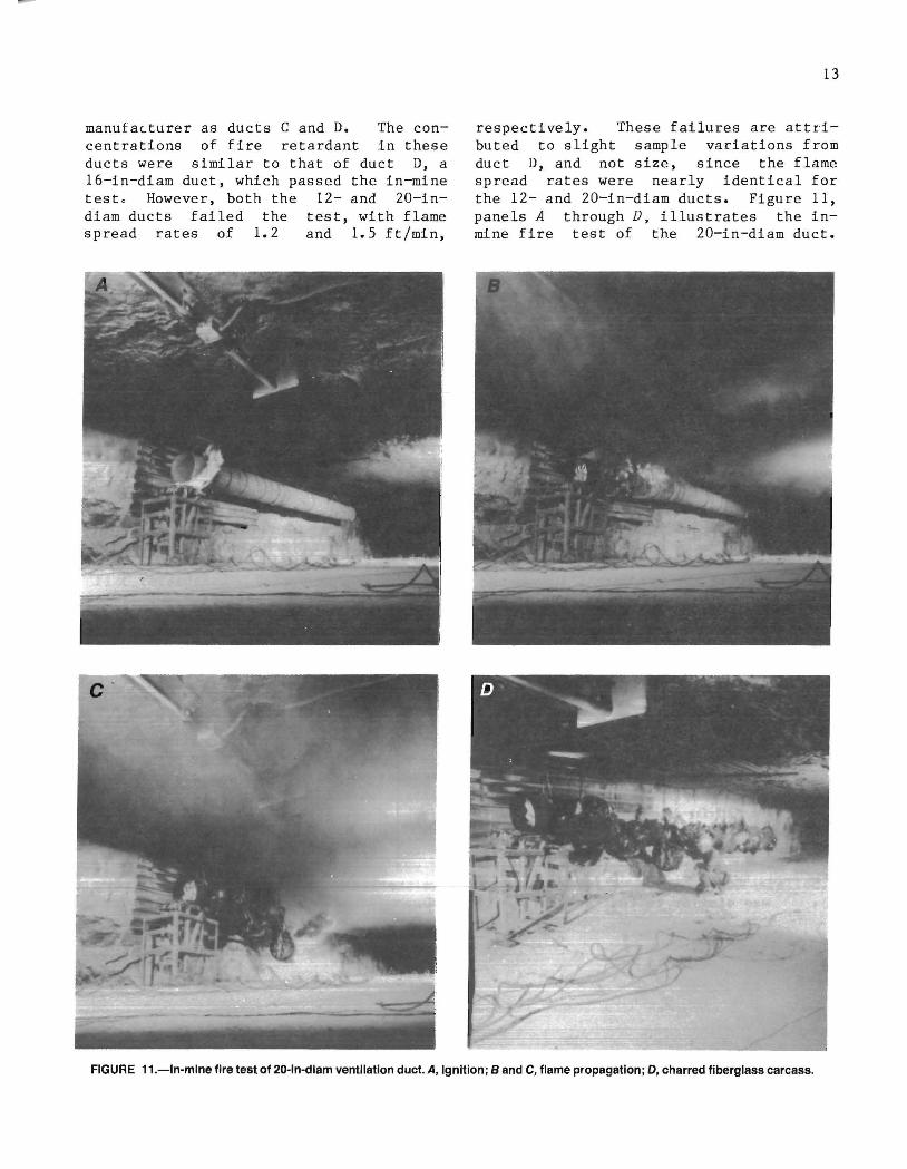
manufacturer as ducts C and D. The concentrations of fire retardant in these ducts were similar to that of duct D, a 16-in-diam duct, which passed the in-mine teste However, both the 12- and 20-indiam ducts failed the test, with flame spread rates of 1.2 and 1.5 ft/min,
13
respectively. These failures are attributed to slight sample variations from duct D, and not size, since the flame spread rates were nearly identical for the 12- and 20-in-diam ducts. Figure 11, panels A through D, illustrates the inmine fire test of the 20-in-diam duct.
FIGURE 11.-ln-mlne fire test of 20-ln-dlam ventilation duct. A, Ignition; Band C, flame propagation; D, charred fiberglass carcass.

14
Panel A shows the start of the test. In panels Band C, the flame front is propagating down the ducting after the ignition source has burned out. Panel D shows the charred fiberglass remains after the test. Approximately 40 wt pct of the original 180 lb of ducting was burned in 16 min.
The flame position versus time for all the ducts that failed the in-mine test is shown in figure 12. The solid lines indicate steady-state flame spread and the slopes of the lines are the flame spread rates. The steeper slopes of most of the dashed lines are a result of the influence of the tray fire. Duct E took more time to reach steady-state burning than did the other samples. These apparant anomalies are expected sinc·e the - -p-r-ocesses that govern ignition and uniform flame propagation are different. Duct C had the fastest flame spread rate of 9.8 ft/min, two to three times greater than the other 16-in-diam duct samples. The flame spread rates of the 12- and 20-in-diam ducts are similar to each other and had the slowest flame spread rates measured in the in-mine tests.
32
28
24
Z 20 o i= Vi 2 16
w ~ 12 ...J 1.L
8
4
o 2 6
KEY
20-in diam
12-in diam
B, C, E, F 16-in diam --- Erratic flame growth - Constant burning
18 20
TIME, min
FIGURE 12.-Flame position versus time for In-mine fire tests of ducts that failed.
The results of all the in-mine tests are summarized in table 5. The table gives the number of feet of ducting that burned, the steady-state flame spread rate, and whether the duct passed or failed the test.
TABLE 5. - Results of full-scale in-mine fire test
Length of duct, Flame spread Duct burned, ft rate,. ft/min Pass or fail
A ••••••••••••••••••••••• 0 of 20 0 Pass. B ••••••••••••••••••••••• 30 of 30 5.6 Fail. e ......•..•.....•.••..•. 30 of 30 9.8 Do. D ••••••••••••••••••••••• 8 of 20 SE Pass. Dl,12-in-diam 1 •••••••••• 30 of 30 1.2 Fail. D2, 20-in-diam 1 ••••••••• 30 of 30 1.5 Do. E ••••••••••••••••••••• a . • 30 of 30 4.3 Do. F ••••••••••••••••••••••• 20 of 20 3.1 Do.
SE Self-extinguished. lConcentration of fire retardant in the 12- and 20-in-diam ducts
was similar to that of the 16-in duct D.

15
CONCLUSIONS AND RECOMMENDATIONS
Of the six 16-in-diam FRP ducts tested in this study, only duct A passed the large-scale vertical fire test, and only duct A and the 16-in-diam duct D passed the full-scale in-mine test. The rapid burning of most of the ducts in the vertical configuration and the sustained flame spread observed in the in-mine tests indicate the need for improved fire resistance, similar to that of duct A. This might be achieved by the addition of more fire retardant to the plastic resin. Because of an increase in the concentration of fire retardant in duct D compared with that in duct C, duct D passed the in-mine test. Although the for mulation for the 12- and 20-in-diam ducts was similar to that for 16-in-diam duct D, they failed the in-mine test. How-ever, the flame spread rates for these ducts were slow compared with those for the other ducts that failed. Duct A was heavier than the other 16-in-diam ducts and contained aluminum trihydrate as the major fire retardant. Unfortunately, the cost of a 10-ft section of duct A is about three times that of the other ducts.
The interpretation of the duct fire behavior in the large-vertical and in-mine tests would be difficult based on the laboratory-scale ASTM fire tests. Several of the ducts that had flame spread indices of 25 or less, failed the largescale vertical and in-mine tests. The limiting oxygen index and flame spread index for duct F was similar to those for duct A, yet duct F failed the vertical and in-mine fire tests, which duct A passed.
The agreement of the results for the five FRP ducts tested by MSHA and the Bureau in the S3FT apparatus was excellent. There was also good agreement between the
S3FT results and the performance of the ducts in the large-scale vertical and full-scale in-mine fire tests. The one exception is duct D, which passed the in-mine test, extinguishing after burning 8 ft, but failed the vertical fire test and S3FT. The agreement between the S3FT and large-scale vertical test could be fortuitous considering the drastic differences in test procedures, such as a vertical versus horizontal duct configuration. Addi tiona1 1arge--sca1e vertical fire tests of ducts that pass the S3Ft are required to verify this agreement. Nevertheless, the S3FT provides a good assessment of the flammability behavior of FRP ducting under realistic test conditions.
Since the completion of this study, several manufacturers have produced FRP ducts that passed all the MSHA voluntary standards for ducting (8). MSHA has issued these ducts a VT (Ventilation Tubing) number, which is stamped on the ducting. The VT ducts pass the S3FT and would probably pass the full-scale i~mine fire test, but might not pass the more severe large-scale vertical test. Due to the rapid burning observed in the vertical fire test, the use of most FRP ducts in vertical runs and steep slopes should be avoided. Since FRP ventilation ducting is used widely in the vertical and sloping configuration in metal and nonmetal mines, the extension of the voluntary acceptance procedures for underground coal mines (8), which includes the S3FT, are recommended for the noncoal mines. In critical areas where FRP ducts are used in shafts, potential duct ignition sources should be eliminated and/pr automatic supression systems installed.

16
REFERENCES
1. Lee, C. K., R. F. Chaiken, J. M. Singer, and M. E. Harris. Behavior of Wood Fires in Model Tunnels Under Forced Ventilation Flow. BuMines RI 8450, 1980, 58 pp.
2. Pittsburgh Press (Pittsburgh, PA). Plenty of Head Room (22 ft diam by 600 ft high fiberglass reinforced plastic chimney stack liner). Nov. 21, 1982, p. Bll.
3. Heskestad, G., and H. Z. You. Fire Protection of Combustible Stacks and Mine Shafts. Phase I: Exposure-Fire Environment and Suppression. Factory Mutual Research Corp., Rep. No. J. I. OFON7.RAjOEOE1, RA, 1982, 102 pp.
4. World Mining Equipment. Sho-t-Resistant Ventilation Tubing. V. 10, No.3, Mar. 1986, p. 10.
5. Baker, R. M., J. Nagy, L. B. McDonald, and J. Wishmyer. An Annotated Bibliography of Metal and Nonmetal Mine Fire Reports (contract J0295035). BuMines OFR 63 (3)-81, 1980, p. 79; NTIS PB 81-223745.
6. U.s. Code of Federal Regulations. Title 30--Mineral Resources; Chapter I-Mine Safety and Health Administration, Department of Labor; Subchapter O--Coal Mine Safety and Health; Part 75--Mandatory Safety Standards--Underground Coal Mines; July 1, 1985.
7. Murphy E. M. Flame Spread Evaluation of Ventilation Cloth. BuMines RI 7625, 1972, 9 pp.
U.S. GOVERNMENT PRINTING OFFICE : 1987 605 ·01 7 /60035 18 5
8. Mine Safety and Health Administration. Standard Application Procedure for the Acceptance of Ventilation Tubing. Feb. 1984, 6 pp.; available from MSHA Approval and Certification Center, Triadelphia, WV.
9. American Society For Testing and Materials. Standard Test Method for Surface Flammability of Materials Using a Radiant Heat Energy Source. E162-83 in 1985 Annual Book of ASTM Standards: Volume 04.07, Building Seals and Sealants; Fire Standards; Building Construction. Philadelphia, PA, 1984, pp. 410-421.
10. Standard Method for Mea-suring the Minimum Oxygen Concentration To Support Candle-Like Combustion of Plastics (Oxygen Index). D2863-77 in 1986 Annual Book of ASTM Standards: Volume 08.02, Plastics (II). Philadelphia, PA, 1985, pp. 637-644.
11. Mattes, R. H., L. V. Wade. Lake Construction, Physical Capability. BuMines 4Q J)p.
A. Bacho, and Lynn Laboratory: Description, and
IC 8911, 1983,
12. American Society for Testing and Materials. Standard Test Method for Gross Calorific Value of Solid Fuel by the Adiabatic Bomb Calorimeter. D2015-77 in 1985 Annual Book of ASTM Standards: Volume 05.05, Gaseous Fuels; Coal and Coke. Philadelphia, PA, 1984, pp. 326-334.
INT.-BU.OF MINES,PGH.,PA. 28472


![Air Infiltration and Ventilation Centre © INIVE EEIG Ductwork ...This paper aims to complement Ventilation Information Paper (VIP)o1 “Airtightness of ventilation ducts” [12].](https://static.fdocuments.net/doc/165x107/6131cb5e1ecc51586944f5ae/air-infiltration-and-ventilation-centre-inive-eeig-ductwork-this-paper-aims.jpg)