Rectangular ducts and fittings - alnor-b2b.com.pl · PDF fileRectangular ducts and fittings...
31
Rectangular ducts and fittings We reserve the right to make changes in the dimensions and technical data products due to their continuous improvement
Transcript of Rectangular ducts and fittings - alnor-b2b.com.pl · PDF fileRectangular ducts and fittings...
Rectangular ducts and fittings
We reserve the right to make changes in the dimensions and technical data products due to their continuous improvement
Kan
ały
i ksz
tałt
ki p
rost
oką
tne
ALNOR® ventilation systemsis a legally protected trademark and technical patent. All rights reserved.
Rect
ang
ula
r d
uct
s an
d fi
tti
ng
sDownload Wentyle
Download AlnorCAMBuy via B2B
SQUER
TECHNICAL INFORMATION
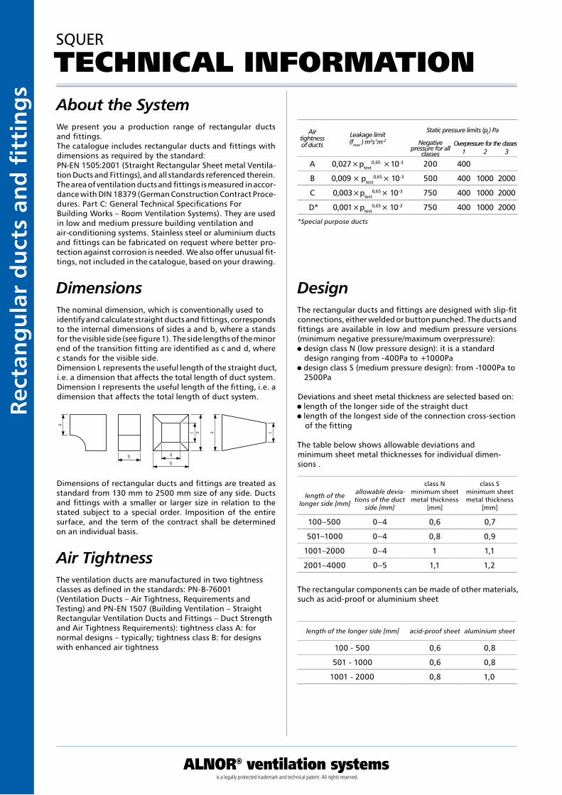
DesignThe rectangular ducts and fittings are designed with slip-fit connections, either welded or button punched. The ducts and fittings are available in low and medium pressure versions (minimum negative pressure/maximum overpressure): design class N (low pressure design): it is a standard design ranging from -400Pa to +1000Pa
design class S (medium pressure design): from -1000Pa to 2500Pa
Deviations and sheet metal thickness are selected based on: length of the longer side of the straight duct length of the longest side of the connection cross-section of the fitting
The table below shows allowable deviations and minimum sheet metal thicknesses for individual dimen-sions .
The rectangular components can be made of other materials, such as acid-proof or aluminium sheet
Air tightness of ducts
Leakage limit(fmax ) m3s-1m-2
Static pressure limits (ps) Pa
Negative pressure for all
classes
Overpressure for the classes1 2 3
*Special purpose ducts
length of the longer side [mm]
allowable devia-tions of the duct
side [mm]
class Nminimum sheet metal thickness
[mm]
class Sminimum sheet metal thickness
[mm]
length of the longer side [mm] acid-proof sheet aluminium sheet
About the System
Dimensions
We present you a production range of rectangular ducts and fittings.The catalogue includes rectangular ducts and fittings with dimensions as required by the standard:PN-EN 1505:2001 (Straight Rectangular Sheet metal Ventila-tion Ducts and Fittings), and all standards referenced therein.The area of ventilation ducts and fittings is measured in accor-dance with DIN 18379 (German Construction Contract Proce-dures. Part C: General Technical Specifications For Building Works – Room Ventilation Systems). They are used in low and medium pressure building ventilation and air-conditioning systems. Stainless steel or aluminium ducts and fittings can be fabricated on request where better pro-tection against corrosion is needed. We also offer unusual fit-tings, not included in the catalogue, based on your drawing.
The nominal dimension, which is conventionally used to identify and calculate straight ducts and fittings, corresponds to the internal dimensions of sides a and b, where a stands for the visible side (see figure 1). The side lengths of the minor end of the transition fitting are identified as c and d, where c stands for the visible side.Dimension L represents the useful length of the straight duct, i.e. a dimension that affects the total length of duct system.Dimension I represents the useful length of the fitting, i.e. a dimension that affects the total length of duct system.
The ventilation ducts are manufactured in two tightness classes as defined in the standards: PN-B-76001 (Ventilation Ducts – Air Tightness, Requirements and Testing) and PN-EN 1507 (Building Ventilation – Straight Rectangular Ventilation Ducts and Fittings – Duct Strength and Air Tightness Requirements): tightness class A: for normal designs – typically; tightness class B: for designs with enhanced air tightness
Air Tightness
Dimensions of rectangular ducts and fittings are treated as standard from 130 mm to 2500 mm size of any side. Ducts and fittings with a smaller or larger size in relation to the stated subject to a special order. Imposition of the entire surface, and the term of the contract shall be determined on an individual basis.
caac
a
b
db
100–500 0–4 0,6 0,7
501–1000 0–4 0,8 0,9
1001–2000 0–4 1 1,1
2001–4000 0–5 1,1 1,2
100 - 500 0,6 0,8
501 - 1000 0,6 0,8
1001 - 2000 0,8 1,0
A 0,027 × ptest0,65 × 10-3 200 400
B 0,009 × ptest0,65 × 10-3 500 400 1000 2000
C 0,003 × ptest0,65 × 10-3 750 400 1000 2000
D* 0,001 × ptest0,65 × 10-3 750 400 1000 2000
ALNOR® ventilation systemsis a legally protected trademark and technical patent. All rights reserved.
Rectang
ular d
ucts an
d fi ttin
gs
Download WentyleDownload AlnorCAM
Buy via B2B
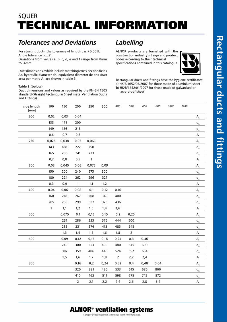
Tolerances and Deviations
SQUER
TECHNICAL INFORMATION
For straight ducts, the tolerance of length L is ±0.005LAngle tolerance is ±2°.Deviations from values a, b, c, d, e and f range from 0mm to -4mm
Duct dimensions, which include matching cross-section fields Ac, hydraulic diameter dh, equivalent diameter de and duct area per metre A, are shown in table 3.
Table 3 (below)Duct dimensions and values as required by the PN-EN 1505 standard (Straight Rectangular Sheet metal Ventilation Ducts and Fittings)..
LabellingALNOR products are furnished with the construction industry’s B sign and product codes according to their technical specifications contained in this catalogue.
Rectangular ducts and fittings have the hygiene certificates:a) HK/B/1652/03/2007 for those made of aluminium sheetb) HK/B/1652/01/2007 for those made of galvanised or acid-proof sheet
side length [mm]
100 150 200 250 300 400 500 600 800 1000 1200
200 0,02 0,03 0,04 Ac
133 171 200 dh
149 186 218 de
0,6 0,7 0,8 Al
250 0,025 0,038 0,05 0,063 Ac
143 188 222 250 dh
165 206 241 273 de
0,7 0,8 0,9 1 Al
300 0,03 0,045 0,06 0,075 0,09 Ac
150 200 240 273 300 dh
180 224 262 296 327 de
0,3 0,9 1 1,1 1,2 Al
400 0,04 0,06 0,08 0,1 0,12 0,16 Ac
160 218 267 308 343 400 dh
205 255 299 337 373 436 de
1 1,1 1,2 1,3 1,4 1,6 Al
500 0,075 0,1 0,13 0,15 0,2 0,25 Ac
231 286 333 375 444 500 dh
283 331 374 413 483 545 de
1,3 1,4 1,5 1,6 1,8 2 Al
600 0,09 0,12 0,15 0,18 0,24 0,3 0,36 Ac
240 300 353 400 480 545 600 dh
307 359 406 448 524 592 654 de
1,5 1,6 1,7 1,8 2 2,2 2,4 Al
800 0,16 0,2 0,24 0,32 0,4 0,48 0,64 Ac
320 381 436 533 615 686 800 dh
410 463 511 598 675 745 872 de
2 2,1 2,2 2,4 2,6 2,8 3,2 Al
Kan
ały
i ksz
tałt
ki p
rost
oką
tne
ALNOR® ventilation systemsis a legally protected trademark and technical patent. All rights reserved.
Rect
ang
ula
r d
uct
s an
d fi
tti
ng
sDownload Wentyle
Download AlnorCAMBuy via B2B
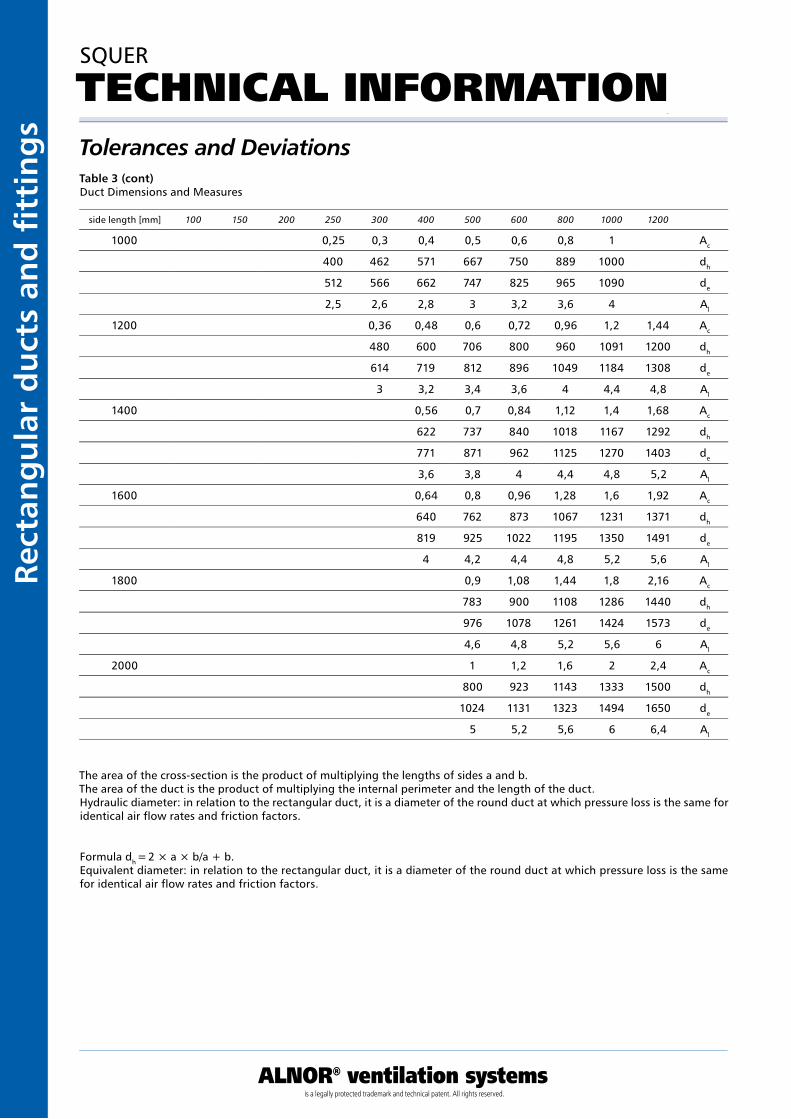
Tolerances and Deviations
SQUER
TECHNICAL INFORMATION
Table 3 (cont) Duct Dimensions and Measures
The area of the cross-section is the product of multiplying the lengths of sides a and b.The area of the duct is the product of multiplying the internal perimeter and the length of the duct.Hydraulic diameter: in relation to the rectangular duct, it is a diameter of the round duct at which pressure loss is the same for identical air flow rates and friction factors.
Formula dh = 2 × a × b/a + b.Equivalent diameter: in relation to the rectangular duct, it is a diameter of the round duct at which pressure loss is the same for identical air flow rates and friction factors.
side length [mm] 100 150 200 250 300 400 500 600 800 1000 1200
1000 0,25 0,3 0,4 0,5 0,6 0,8 1 Ac
400 462 571 667 750 889 1000 dh
512 566 662 747 825 965 1090 de
2,5 2,6 2,8 3 3,2 3,6 4 Al
1200 0,36 0,48 0,6 0,72 0,96 1,2 1,44 Ac
480 600 706 800 960 1091 1200 dh
614 719 812 896 1049 1184 1308 de
3 3,2 3,4 3,6 4 4,4 4,8 Al
1400 0,56 0,7 0,84 1,12 1,4 1,68 Ac
622 737 840 1018 1167 1292 dh
771 871 962 1125 1270 1403 de
3,6 3,8 4 4,4 4,8 5,2 Al
1600 0,64 0,8 0,96 1,28 1,6 1,92 Ac
640 762 873 1067 1231 1371 dh
819 925 1022 1195 1350 1491 de
4 4,2 4,4 4,8 5,2 5,6 Al
1800 0,9 1,08 1,44 1,8 2,16 Ac
783 900 1108 1286 1440 dh
976 1078 1261 1424 1573 de
4,6 4,8 5,2 5,6 6 Al
2000 1 1,2 1,6 2 2,4 Ac
800 923 1143 1333 1500 dh
1024 1131 1323 1494 1650 de
5 5,2 5,6 6 6,4 Al
ALNOR® ventilation systemsis a legally protected trademark and technical patent. All rights reserved.
Rectang
ular d
ucts an
d fi ttin
gs
Download WentyleDownload AlnorCAM
Buy via B2B
Rigidity
SQUER
TECHNICAL INFORMATION
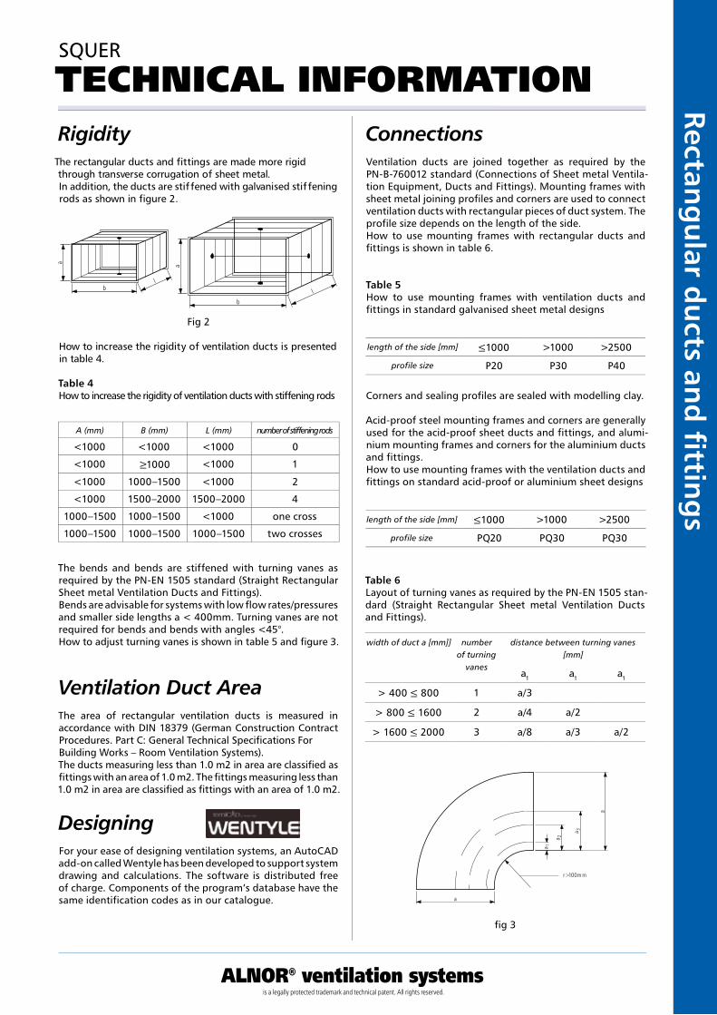
The rectangular ducts and fittings are made more rigid through transverse corrugation of sheet metal.In addition, the ducts are stif fened with galvanised stif fening rods as shown in figure 2.
How to increase the rigidity of ventilation ducts is presented in table 4.
Fig 2
fig 3
Table 4How to increase the rigidity of ventilation ducts with stiffening rods
The bends and bends are stiffened with turning vanes as required by the PN-EN 1505 standard (Straight Rectangular Sheet metal Ventilation Ducts and Fittings).Bends are advisable for systems with low flow rates/pressures and smaller side lengths a < 400mm. Turning vanes are not required for bends and bends with angles <45°.How to adjust turning vanes is shown in table 5 and figure 3.
ConnectionsVentilation ducts are joined together as required by the PN-B-760012 standard (Connections of Sheet metal Ventila-tion Equipment, Ducts and Fittings). Mounting frames with sheet metal joining profiles and corners are used to connect ventilation ducts with rectangular pieces of duct system. The profile size depends on the length of the side.How to use mounting frames with rectangular ducts and fittings is shown in table 6.
Table 5How to use mounting frames with ventilation ducts and fittings in standard galvanised sheet metal designs
Corners and sealing profiles are sealed with modelling clay.
Acid-proof steel mounting frames and corners are generally used for the acid-proof sheet ducts and fittings, and alumi-nium mounting frames and corners for the aluminium ducts and fittings.How to use mounting frames with the ventilation ducts and fittings on standard acid-proof or aluminium sheet designs
Table 6Layout of turning vanes as required by the PN-EN 1505 stan-dard (Straight Rectangular Sheet metal Ventilation Ducts and Fittings).
Ventilation Duct AreaThe area of rectangular ventilation ducts is measured in accordance with DIN 18379 (German Construction Contract Procedures. Part C: General Technical Specifications For Building Works – Room Ventilation Systems).The ducts measuring less than 1.0 m2 in area are classified as fittings with an area of 1.0 m2. The fittings measuring less than 1.0 m2 in area are classified as fittings with an area of 1.0 m2.
For your ease of designing ventilation systems, an AutoCAD add-on called Wentyle has been developed to support system drawing and calculations. The software is distributed free of charge. Components of the program’s database have the same identification codes as in our catalogue.
A (mm) B (mm) L (mm) number of stiffening rods
one cross
two crosses
length of the side [mm]
profile size
length of the side [mm]
profile size
width of duct a [mm]] number of turning
vanes
distance between turning vanes [mm]
Designing
l
l
aa
b
b
r>100mm
a 1
a 2
a 3
a
a
<1000 <1000 <1000 0
<1000 ≥1000 <1000 1
<1000 1000–1500 <1000 2
<1000 1500–2000 1500–2000 4
1000–1500 1000–1500 <1000
1000–1500 1000–1500 1000–1500
≤1000 >1000 >2500
P20 P30 P40
≤1000 >1000 >2500
PQ20 PQ30 PQ30
a1 a1 a1
> 400 ≤ 800 1 a/3
> 800 ≤ 1600 2 a/4 a/2
> 1600 ≤ 2000 3 a/8 a/3 a/2
Kan
ały
i ksz
tałt
ki p
rost
oką
tne
ALNOR® ventilation systemsis a legally protected trademark and technical patent. All rights reserved.
Rect
ang
ula
r d
uct
s an
d fi
tti
ng
sDownload Wentyle
Download AlnorCAMBuy via B2B
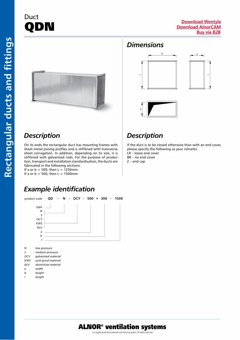
Duct
QDNDimensions
DescriptionOn its ends the rectangular duct has mounting frames with sheet metal joining profiles and is stiffened with transverse sheet corrugation. In addition, depending on its size, it is stiffened with galvanised rods. For the purpose of produc-tion, transport and installation standardisation, the ducts are fabricated in the following sections:If a or b < 500, then L = 1250mm If a or b > 500, then L = 1500mm
If the duct is to be closed otherwise than with an end cover, please specify the following as your remarks: LR – loose end coverBR – no end coverZ – end cap
product code QD - N - OCY - 500 × 300 - 1500
typeNS
OCYKWSALU
abl
Example identification
N low pressureS medium pressureOCY galvanised materialKWS acid-proof materialALU aluminium materiala widthb heightl length
Description
ALNOR® ventilation systemsis a legally protected trademark and technical patent. All rights reserved.
Rectang
ular d
ucts an
d fi ttin
gs
Download WentyleDownload AlnorCAM
Buy via B2B
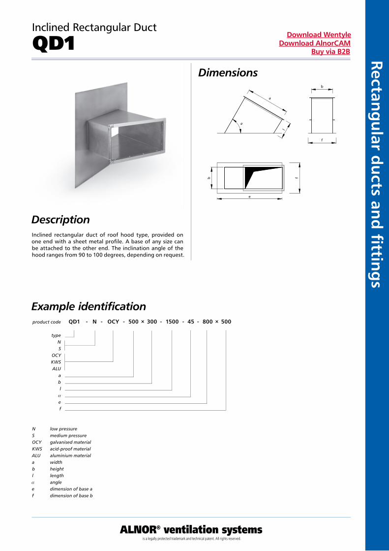
Inclined Rectangular Duct
QD1Dimensions
DescriptionInclined rectangular duct of roof hood type, provided on one end with a sheet metal profile. A base of any size can be attached to the other end. The inclination angle of the hood ranges from 90 to 100 degrees, depending on request.
product code QD1 - N - OCY - 500 × 300 - 1500 - 45 - 800 × 500
typeNS
OCYKWSALU
abl
a
ef
Example identification
N low pressureS medium pressureOCY galvanised materialKWS acid-proof materialALU aluminium materiala widthb heightl lengtha anglee dimension of base af dimension of base b
Kan
ały
i ksz
tałt
ki p
rost
oką
tne
ALNOR® ventilation systemsis a legally protected trademark and technical patent. All rights reserved.
Rect
ang
ula
r d
uct
s an
d fi
tti
ng
sDownload Wentyle
Download AlnorCAMBuy via B2B
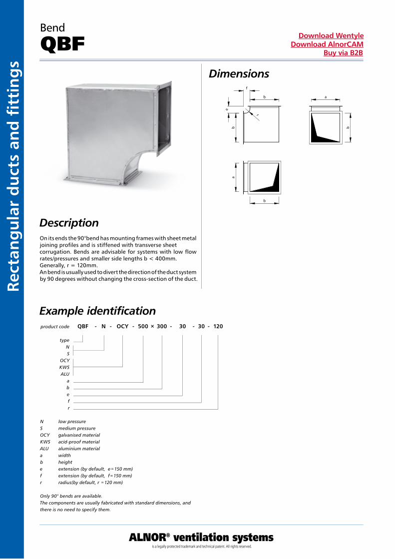
Bend
QBFDimensions
Description
product code QBF - N - OCY - 500 × 300 - 30 - 30 - 120
typeNS
OCYKWSALU
abefr
Example identification
N low pressureS medium pressureOCY galvanised materialKWS acid-proof materialALU aluminium materiala widthb heighte extension (by default, e = 150 mm)f extension (by default, f = 150 mm)r radius(by default, r = 120 mm)
Only 90° bends are available.The components are usually fabricated with standard dimensions, and there is no need to specify them.
On its ends the 90°bend has mounting frames with sheet metal joining profiles and is stiffened with transverse sheet corrugation. Bends are advisable for systems with low flow rates/pressures and smaller side lengths b < 400mm. Generally, r = 120mm.An bend is usually used to divert the direction of the duct system by 90 degrees without changing the cross-section of the duct.
ALNOR® ventilation systemsis a legally protected trademark and technical patent. All rights reserved.
Rectang
ular d
ucts an
d fi ttin
gs
Download WentyleDownload AlnorCAM
Buy via B2B
Variable Cross-Section Bend
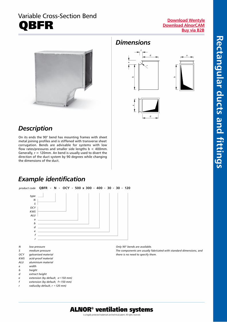
QBFRDimensions
DescriptionOn its ends the 90° bend has mounting frames with sheet metal joining profiles and is stiffened with transverse sheet corrugation. Bends are advisable for systems with low flow rates/pressures and smaller side lengths b < 400mm. Generally, r = 120mm. An bend is usually used to divert the direction of the duct system by 90 degrees while changing the dimensions of the duct.
product code QBFR - N - OCY - 500 x 300 - 400 - 30 - 30 - 120
typeNS
OCYKWSALU
abdefr
Example identification
N low pressureS medium pressureOCY galvanised materialKWS acid-proof materialALU aluminium materiala widthb heightd extract heighte extension (by default, e = 150 mm)f extension (by default, f = 150 mm)r radius(by default, r = 120 mm)
Only 90° bends are available.The components are usually fabricated with standard dimensions, and there is no need to specify them.
Kan
ały
i ksz
tałt
ki p
rost
oką
tne
ALNOR® ventilation systemsis a legally protected trademark and technical patent. All rights reserved.
Rect
ang
ula
r d
uct
s an
d fi
tti
ng
sDownload Wentyle
Download AlnorCAMBuy via B2B
Bend
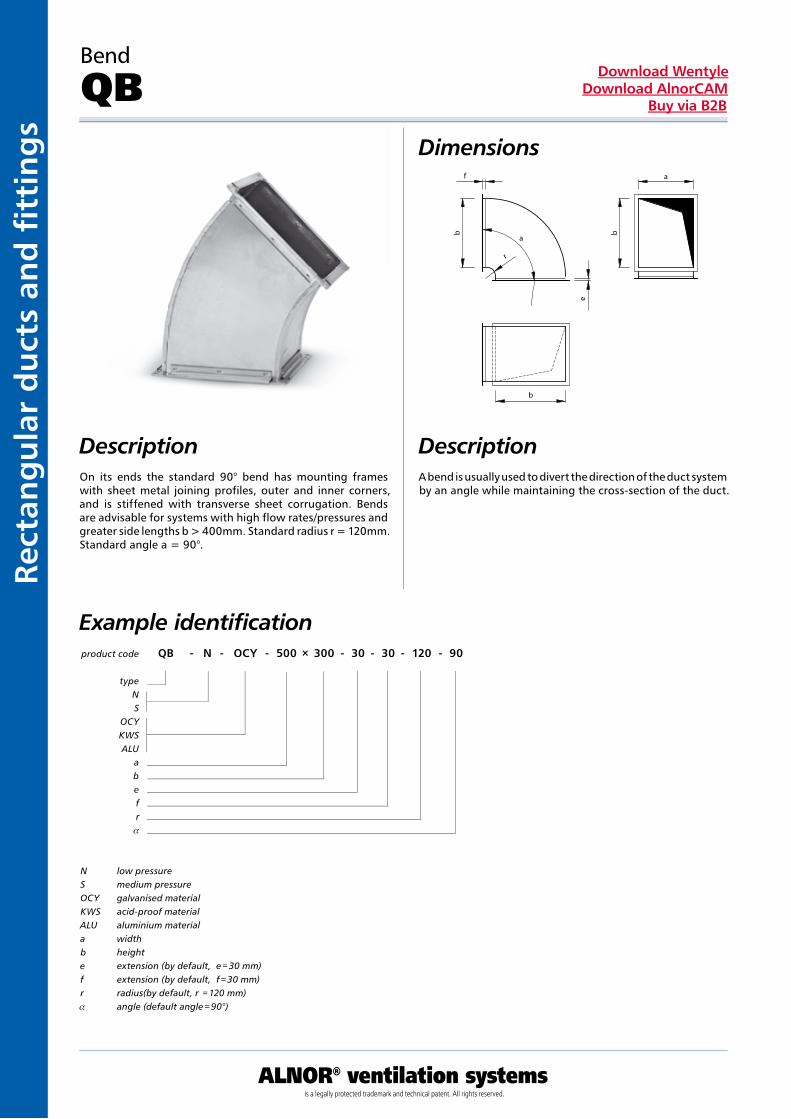
QBDimensions
product code QB - N - OCY - 500 × 300 - 30 - 30 - 120 - 90
typeNS
OCYKWSALU
abefr
a
Example identification
N low pressureS medium pressureOCY galvanised materialKWS acid-proof materialALU aluminium materiala widthb heighte extension (by default, e = 30 mm)f extension (by default, f = 30 mm)r radius(by default, r = 120 mm)a angle (default angle = 90°)
DescriptionOn its ends the standard 90° bend has mounting frames with sheet metal joining profiles, outer and inner corners, and is stiffened with transverse sheet corrugation. Bends are advisable for systems with high flow rates/pressures and greater side lengths b > 400mm. Standard radius r = 120mm. Standard angle a = 90°.
A bend is usually used to divert the direction of the duct system by an angle while maintaining the cross-section of the duct.
Description
ALNOR® ventilation systemsis a legally protected trademark and technical patent. All rights reserved.
Rectang
ular d
ucts an
d fi ttin
gs
Download WentyleDownload AlnorCAM
Buy via B2B
Variable Cross-Section Bend
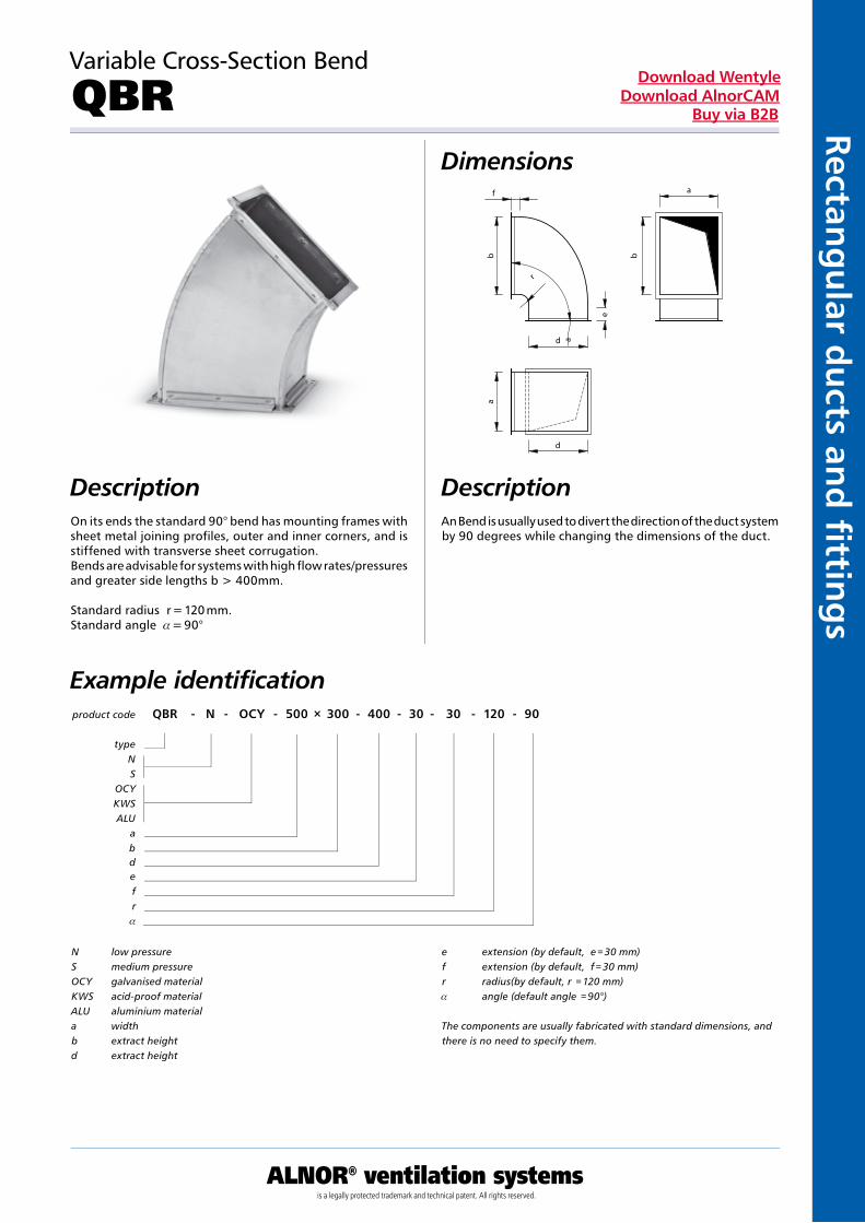
QBRDimensions
Description
product code QBR - N - OCY - 500 × 300 - 400 - 30 - 30 - 120 - 90
typeNS
OCYKWSALU
abdefr
a
Example identification
N low pressureS medium pressureOCY galvanised materialKWS acid-proof materialALU aluminium materiala widthb extract heightd extract height
e extension (by default, e = 30 mm)f extension (by default, f = 30 mm)r radius(by default, r = 120 mm)a angle (default angle = 90°)
The components are usually fabricated with standard dimensions, and there is no need to specify them.
On its ends the standard 90° bend has mounting frames with sheet metal joining profiles, outer and inner corners, and is stiffened with transverse sheet corrugation. Bends are advisable for systems with high flow rates/pressures and greater side lengths b > 400mm.
Standard radius r = 120 mm.Standard angle a = 90°
An Bend is usually used to divert the direction of the duct system by 90 degrees while changing the dimensions of the duct.
Description
Kan
ały
i ksz
tałt
ki p
rost
oką
tne
ALNOR® ventilation systemsis a legally protected trademark and technical patent. All rights reserved.
Rect
ang
ula
r d
uct
s an
d fi
tti
ng
sDownload Wentyle
Download AlnorCAMBuy via B2B
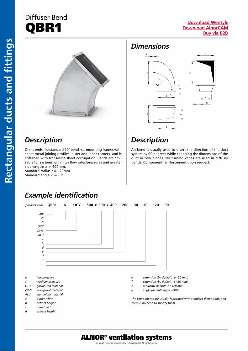
Diffuser Bend
QBR1Dimensions
DescriptionOn its ends the standard 90° bend has mounting frames with sheet metal joining profiles, outer and inner corners, and is stiffened with transverse sheet corrugation. Bends are advi-sable for systems with high flow rates/pressures and greater side lengths a > 400mm.Standard radius r = 120mmStandard angle a = 90°
An bend is usually used to divert the direction of the duct system by 90 degrees while changing the dimensions of the duct in two planes. No turning vanes are used in diffuser bends. Component reinforcement upon request.
product code QBR1 - N - OCY - 500 x 300 x 400 - 200 - 30 - 30 - 120 - 90
typeNS
OCYKWSALU
abdefr
a
Example identification
N low pressureS medium pressureOCY galvanised materialKWS acid-proof materialALU aluminium materiala outlet widthb extract heightc outlet widthd extract height
e extension (by default, e = 30 mm)f extension (by default, f = 30 mm)r radius(by default, r = 120 mm)a angle (default angle = 90°)
The components are usually fabricated with standard dimensions, and there is no need to specify them.
Description
ALNOR® ventilation systemsis a legally protected trademark and technical patent. All rights reserved.
Rectang
ular d
ucts an
d fi ttin
gs
Download WentyleDownload AlnorCAM
Buy via B2B
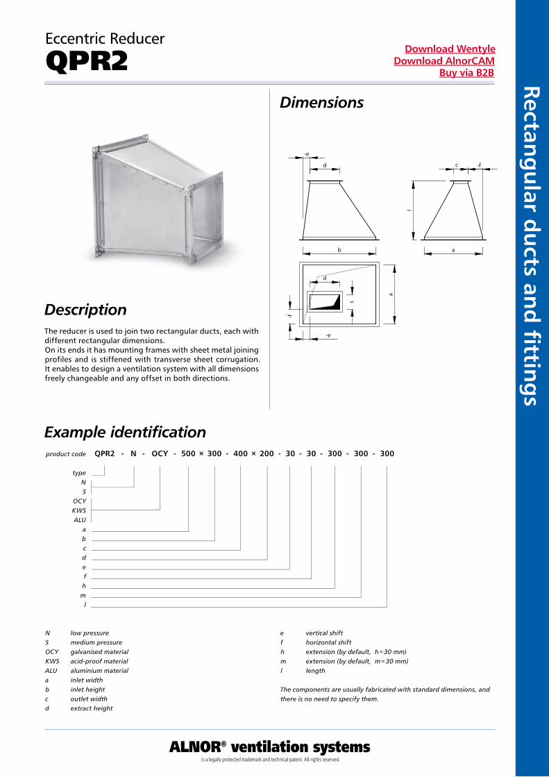
Eccentric Reducer
QPR2Dimensions
DescriptionThe reducer is used to join two rectangular ducts, each with different rectangular dimensions.On its ends it has mounting frames with sheet metal joining profiles and is stiffened with transverse sheet corrugation. It enables to design a ventilation system with all dimensions freely changeable and any offset in both directions.
product code QPR2 - N - OCY - 500 × 300 - 400 × 200 - 30 - 30 - 300 - 300 - 300
typeNS
OCYKWSALU
abcdefhm
l
Example identification
N low pressureS medium pressureOCY galvanised materialKWS acid-proof materialALU aluminium materiala inlet widthb inlet heightc outlet widthd extract height
e vertical shiftf horizontal shifth extension (by default, h = 30 mm)m extension (by default, m = 30 mm)l length
The components are usually fabricated with standard dimensions, and there is no need to specify them.
Kan
ały
i ksz
tałt
ki p
rost
oką
tne
ALNOR® ventilation systemsis a legally protected trademark and technical patent. All rights reserved.
Rect
ang
ula
r d
uct
s an
d fi
tti
ng
sDownload Wentyle
Download AlnorCAMBuy via B2B
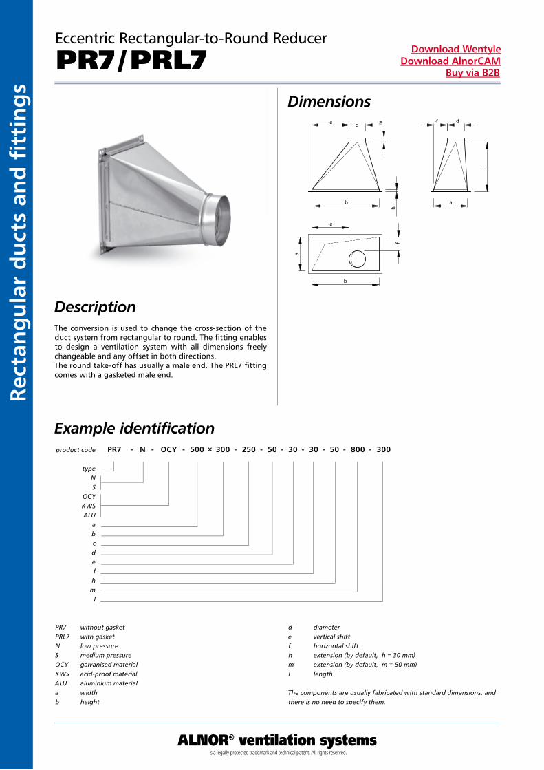
Eccentric Rectangular-to-Round Reducer
PR7 / PRL7Dimensions
DescriptionThe conversion is used to change the cross-section of the duct system from rectangular to round. The fitting enables to design a ventilation system with all dimensions freely changeable and any offset in both directions.The round take-off has usually a male end. The PRL7 fitting comes with a gasketed male end.
product code PR7 - N - OCY - 500 × 300 - 250 - 50 - 30 - 30 - 50 - 800 - 300
typeNS
OCYKWSALU
abcdefhm
l
Example identification
PR7 without gasketPRL7 with gasketN low pressureS medium pressureOCY galvanised materialKWS acid-proof materialALU aluminium materiala widthb height
d diametere vertical shiftf horizontal shifth extension (by default, h = 30 mm)m extension (by default, m = 50 mm)l length
The components are usually fabricated with standard dimensions, and there is no need to specify them.
ALNOR® ventilation systemsis a legally protected trademark and technical patent. All rights reserved.
Rectang
ular d
ucts an
d fi ttin
gs
Download WentyleDownload AlnorCAM
Buy via B2B
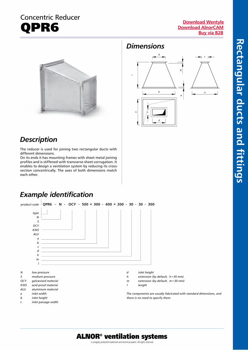
Concentric Reducer
QPR6Dimensions
DescriptionThe reducer is used for joining two rectangular ducts with different dimensions.On its ends it has mounting frames with sheet metal joining profiles and is stiffened with transverse sheet corrugation. It enables to design a ventilation system by reducing its cross-section concentrically. The axes of both dimensions match each other.
product code QPR6 - N - OCY - 500 × 300 - 400 × 200 - 30 - 30 - 300
typeNS
OCYKWSALU
abcdhm
l
Example identification
N low pressureS medium pressureOCY galvanised materialKWS acid-proof materialALU aluminium materiala inlet widthb inlet heightc inlet passage width
d inlet heighth extension (by default, h = 30 mm)m extension (by default, m = 30 mm)l length
The components are usually fabricated with standard dimensions, and there is no need to specify them.
Kan
ały
i ksz
tałt
ki p
rost
oką
tne
ALNOR® ventilation systemsis a legally protected trademark and technical patent. All rights reserved.
Rect
ang
ula
r d
uct
s an
d fi
tti
ng
sDownload Wentyle
Download AlnorCAMBuy via B2B
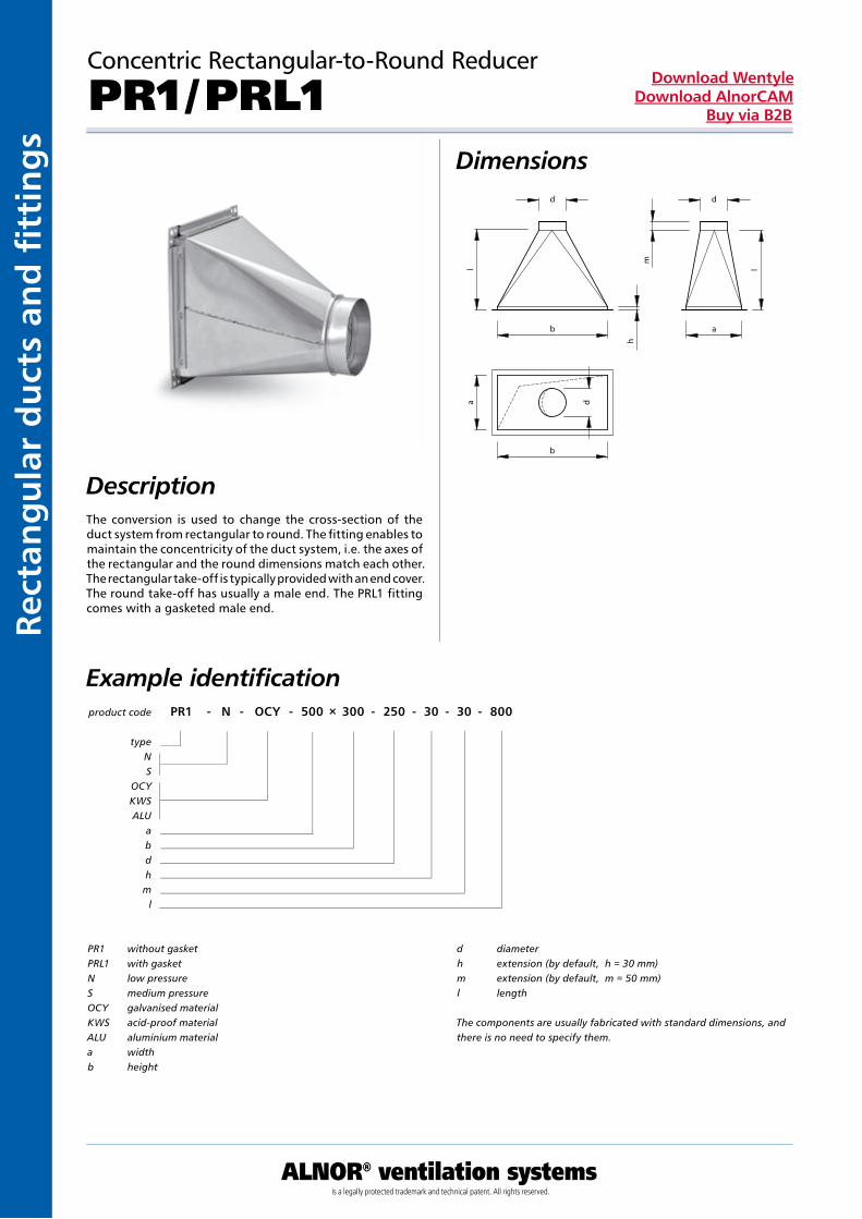
Concentric Rectangular-to-Round Reducer
PR1 / PRL1Dimensions
DescriptionThe conversion is used to change the cross-section of the duct system from rectangular to round. The fitting enables to maintain the concentricity of the duct system, i.e. the axes of the rectangular and the round dimensions match each other. The rectangular take-off is typically provided with an end cover.The round take-off has usually a male end. The PRL1 fitting comes with a gasketed male end.
product code PR1 - N - OCY - 500 × 300 - 250 - 30 - 30 - 800
typeNS
OCYKWSALU
abdhm
l
Example identification
PR1 without gasketPRL1 with gasketN low pressureS medium pressureOCY galvanised materialKWS acid-proof materialALU aluminium materiala widthb height
d diameterh extension (by default, h = 30 mm)m extension (by default, m = 50 mm)l length
The components are usually fabricated with standard dimensions, and there is no need to specify them.
ALNOR® ventilation systemsis a legally protected trademark and technical patent. All rights reserved.
Rectang
ular d
ucts an
d fi ttin
gs
Download WentyleDownload AlnorCAM
Buy via B2B
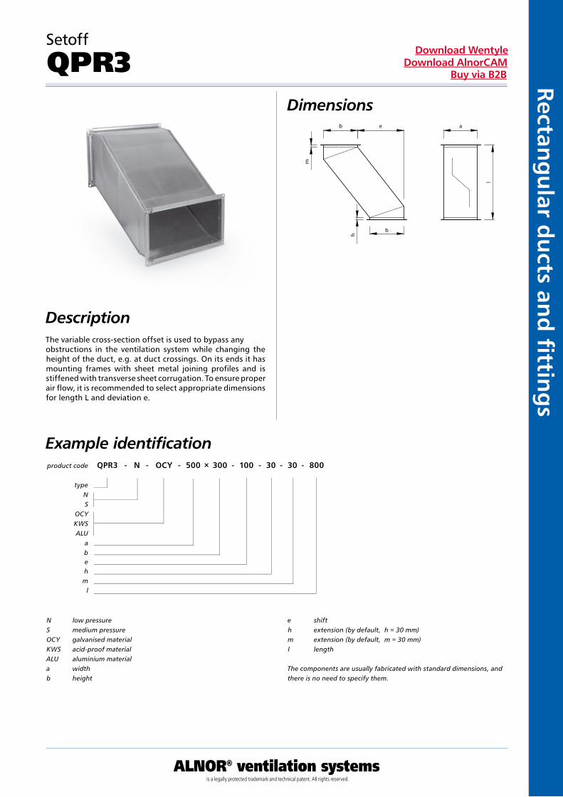
Setoff
QPR3Dimensions
DescriptionThe variable cross-section offset is used to bypass any obstructions in the ventilation system while changing the height of the duct, e.g. at duct crossings. On its ends it has mounting frames with sheet metal joining profiles and is stiffened with transverse sheet corrugation. To ensure proper air flow, it is recommended to select appropriate dimensions for length L and deviation e.
product code QPR3 - N - OCY - 500 × 300 - 100 - 30 - 30 - 800
typeNS
OCYKWSALU
abehm
l
Example identification
N low pressureS medium pressureOCY galvanised materialKWS acid-proof materialALU aluminium materiala widthb height
e shift h extension (by default, h = 30 mm)m extension (by default, m = 30 mm)l length
The components are usually fabricated with standard dimensions, and there is no need to specify them.
Kan
ały
i ksz
tałt
ki p
rost
oką
tne
ALNOR® ventilation systemsis a legally protected trademark and technical patent. All rights reserved.
Rect
ang
ula
r d
uct
s an
d fi
tti
ng
sDownload Wentyle
Download AlnorCAMBuy via B2B
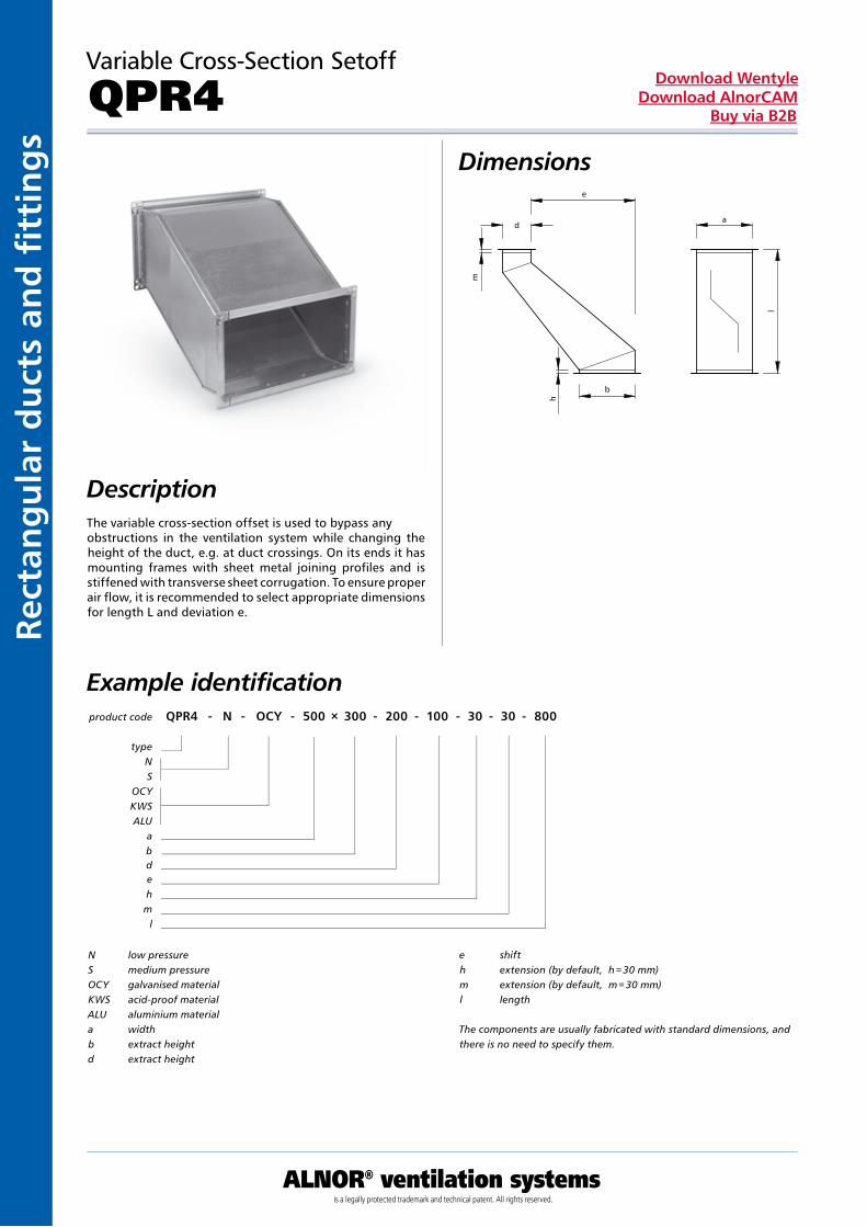
Variable Cross-Section Setoff
QPR4Dimensions
DescriptionThe variable cross-section offset is used to bypass any obstructions in the ventilation system while changing the height of the duct, e.g. at duct crossings. On its ends it has mounting frames with sheet metal joining profiles and is stiffened with transverse sheet corrugation. To ensure proper air flow, it is recommended to select appropriate dimensions for length L and deviation e.
product code QPR4 - N - OCY - 500 × 300 - 200 - 100 - 30 - 30 - 800
typeNS
OCYKWSALU
abdehm
l
Example identification
N low pressureS medium pressureOCY galvanised materialKWS acid-proof materialALU aluminium materiala widthb extract heightd extract height
e shifth extension (by default, h = 30 mm)m extension (by default, m = 30 mm)l length
The components are usually fabricated with standard dimensions, and there is no need to specify them.
ALNOR® ventilation systemsis a legally protected trademark and technical patent. All rights reserved.
Rectang
ular d
ucts an
d fi ttin
gs
Download WentyleDownload AlnorCAM
Buy via B2B
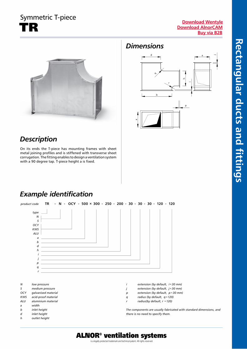
Symmetric T-piece
TRDimensions
DescriptionOn its ends the T-piece has mounting frames with sheet metal joining profiles and is stiffened with transverse sheet corrugation. The fitting enables to design a ventilation system with a 90 degree tap. T-piece height a is fixed.
product code TR - N - OCY - 500 × 300 - 250 - 200 - 30 - 30 - 30 - 120 - 120
typeNS
OCYKWSALU
abdhij
pqr
Example identification
N low pressureS medium pressureOCY galvanised materialKWS acid-proof materialALU aluminium materiala widthb inlet heightd inlet heighth outlet height
i extension (by default, i = 30 mm)j extension (by default, j = 30 mm)p extension (by default, p = 30 mm)q radius (by default, q = 120)r radius(by default, r = 120)
The components are usually fabricated with standard dimensions, and there is no need to specify them.
Kan
ały
i ksz
tałt
ki p
rost
oką
tne
ALNOR® ventilation systemsis a legally protected trademark and technical patent. All rights reserved.
Rect
ang
ula
r d
uct
s an
d fi
tti
ng
sDownload Wentyle
Download AlnorCAMBuy via B2B
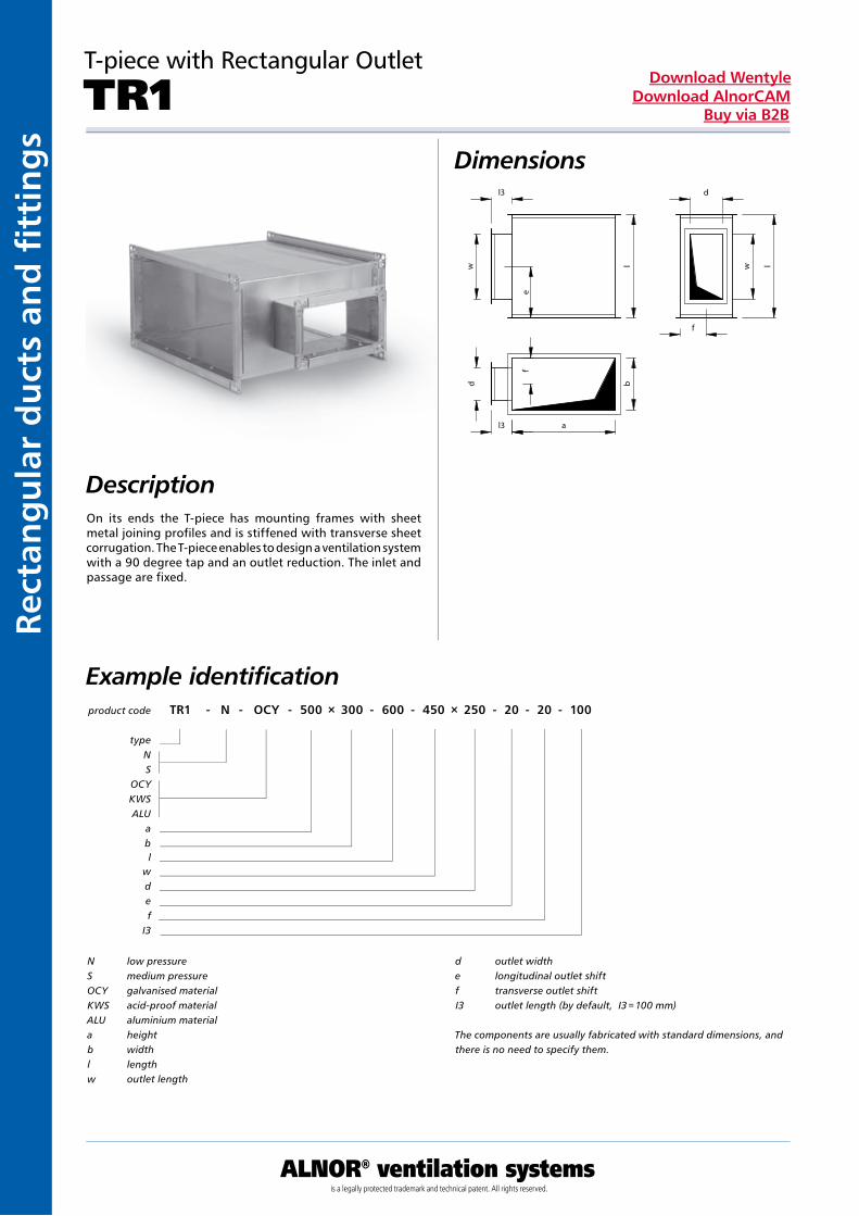
T-piece with Rectangular Outlet
TR1Dimensions
Description
product code TR1 - N - OCY - 500 × 300 - 600 - 450 × 250 - 20 - 20 - 100
typeNS
OCYKWSALU
abl
wdef
I3
Example identification
N low pressureS medium pressureOCY galvanised materialKWS acid-proof materialALU aluminium materiala heightb widthl lengthw outlet length
d outlet widthe longitudinal outlet shiftf transverse outlet shiftI3 outlet length (by default, I3 = 100 mm)
The components are usually fabricated with standard dimensions, and there is no need to specify them.
On its ends the T-piece has mounting frames with sheet metal joining profiles and is stiffened with transverse sheet corrugation. The T-piece enables to design a ventilation system with a 90 degree tap and an outlet reduction. The inlet and passage are fixed.
ALNOR® ventilation systemsis a legally protected trademark and technical patent. All rights reserved.
Rectang
ular d
ucts an
d fi ttin
gs
Download WentyleDownload AlnorCAM
Buy via B2B
Tapered T-piece
TR7Dimensions
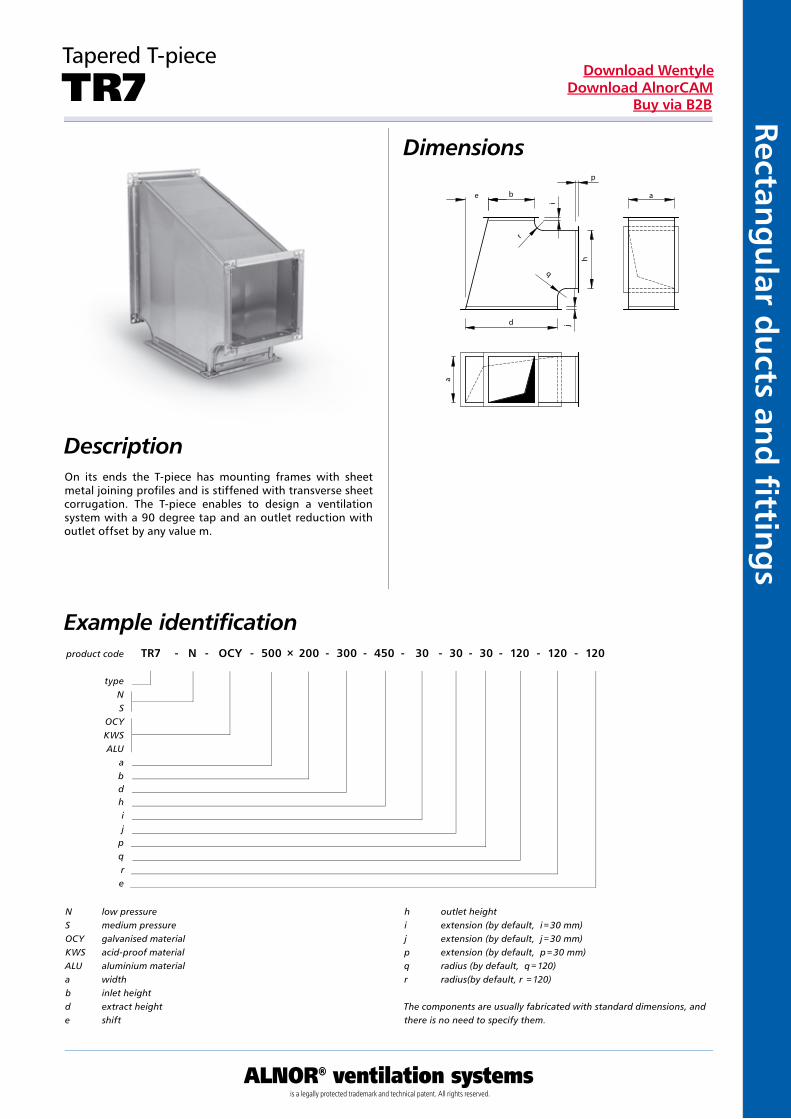
DescriptionOn its ends the T-piece has mounting frames with sheet metal joining profiles and is stiffened with transverse sheet corrugation. The T-piece enables to design a ventilation system with a 90 degree tap and an outlet reduction with outlet offset by any value m.
product code TR7 - N - OCY - 500 × 200 - 300 - 450 - 30 - 30 - 30 - 120 - 120 - 120
typeNS
OCYKWSALU
abdhij
pqre
Example identification
N low pressureS medium pressureOCY galvanised materialKWS acid-proof materialALU aluminium materiala widthb inlet heightd extract heighte shift
h outlet heighti extension (by default, i = 30 mm)j extension (by default, j = 30 mm)p extension (by default, p = 30 mm)q radius (by default, q = 120)r radius(by default, r = 120)
The components are usually fabricated with standard dimensions, and there is no need to specify them.
q
h
j
e
d
a
b
r
a
i
p
Kan
ały
i ksz
tałt
ki p
rost
oką
tne
ALNOR® ventilation systemsis a legally protected trademark and technical patent. All rights reserved.
Rect
ang
ula
r d
uct
s an
d fi
tti
ng
sDownload Wentyle
Download AlnorCAMBuy via B2B
Concentric Taper T-piece
TR8Dimensions
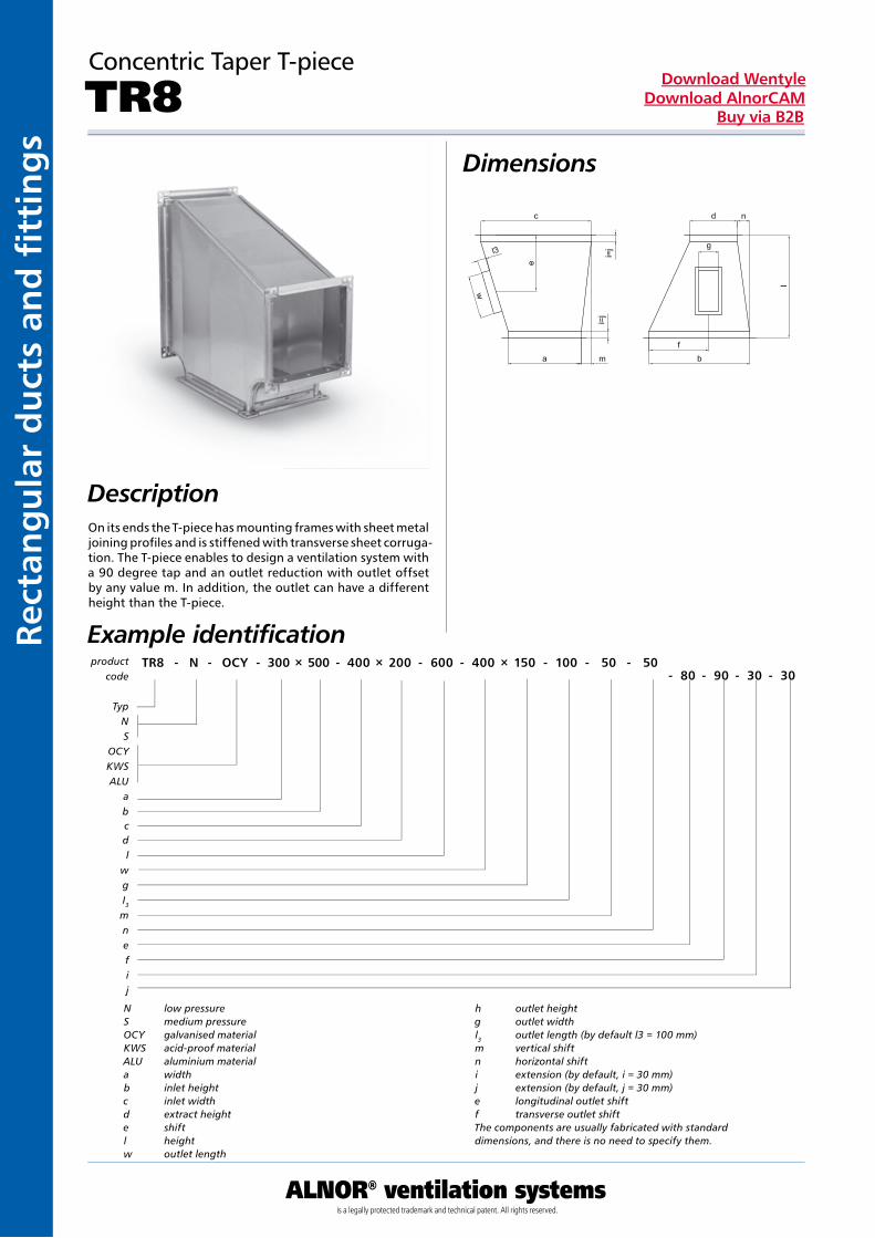
DescriptionOn its ends the T-piece has mounting frames with sheet metal joining profiles and is stiffened with transverse sheet corruga-tion. The T-piece enables to design a ventilation system with a 90 degree tap and an outlet reduction with outlet offset by any value m. In addition, the outlet can have a different height than the T-piece.
Example identification
N low pressureS medium pressureOCY galvanised materialKWS acid-proof materialALU aluminium materiala widthb inlet heightc inlet widthd extract heighte shiftl heightw outlet length
h outlet heightg outlet widthl3 outlet length (by default l3 = 100 mm)m vertical shiftn horizontal shifti extension (by default, i = 30 mm)j extension (by default, j = 30 mm)e longitudinal outlet shiftf transverse outlet shiftThe components are usually fabricated with standard dimensions, and there is no need to specify them.
product code
TR8 - N - OCY - 300 × 500 - 400 × 200 - 600 - 400 × 150 - 100 - 50 - 50- 80 - 90 - 30 - 30
TypNS
OCYKWSALU
abcdl
wgI3mnefij
ALNOR® ventilation systemsis a legally protected trademark and technical patent. All rights reserved.
Rectang
ular d
ucts an
d fi ttin
gs
Download WentyleDownload AlnorCAM
Buy via B2B
Symmetric Taper T-piece
TR9Dimensions
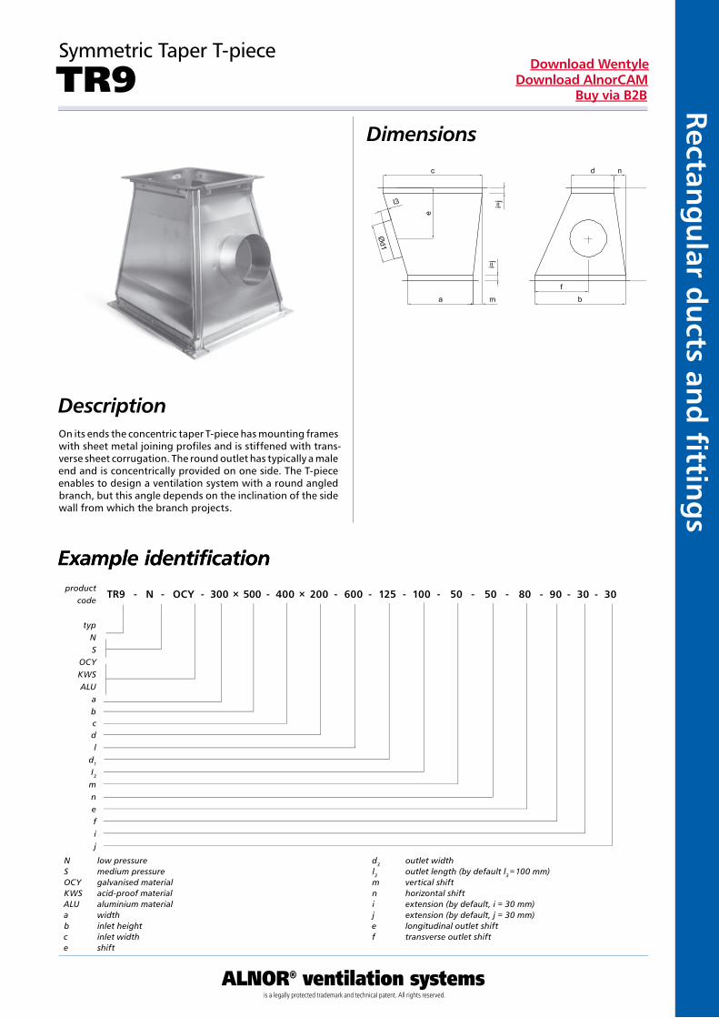
DescriptionOn its ends the concentric taper T-piece has mounting frames with sheet metal joining profiles and is stiffened with trans-verse sheet corrugation. The round outlet has typically a male end and is concentrically provided on one side. The T-piece enables to design a ventilation system with a round angled branch, but this angle depends on the inclination of the side wall from which the branch projects.
Example identificationExample identification
N low pressureS medium pressureOCY galvanised materialKWS acid-proof materialALU aluminium materiala widthb inlet heightc inlet widthe shift
d3 outlet widthl3 outlet length (by default l3 = 100 mm)m vertical shiftn horizontal shifti extension (by default, i = 30 mm)j extension (by default, j = 30 mm)e longitudinal outlet shiftf transverse outlet shift
product code
TR9 - N - OCY - 300 × 500 - 400 × 200 - 600 - 125 - 100 - 50 - 50 - 80 - 90 - 30 - 30
typNS
OCYKWSALU
abcdl
d1
I3mnefij
Kan
ały
i ksz
tałt
ki p
rost
oką
tne
ALNOR® ventilation systemsis a legally protected trademark and technical patent. All rights reserved.
Rect
ang
ula
r d
uct
s an
d fi
tti
ng
sDownload Wentyle
Download AlnorCAMBuy via B2B
X-piece with Round Taps
CZ2Dimensions
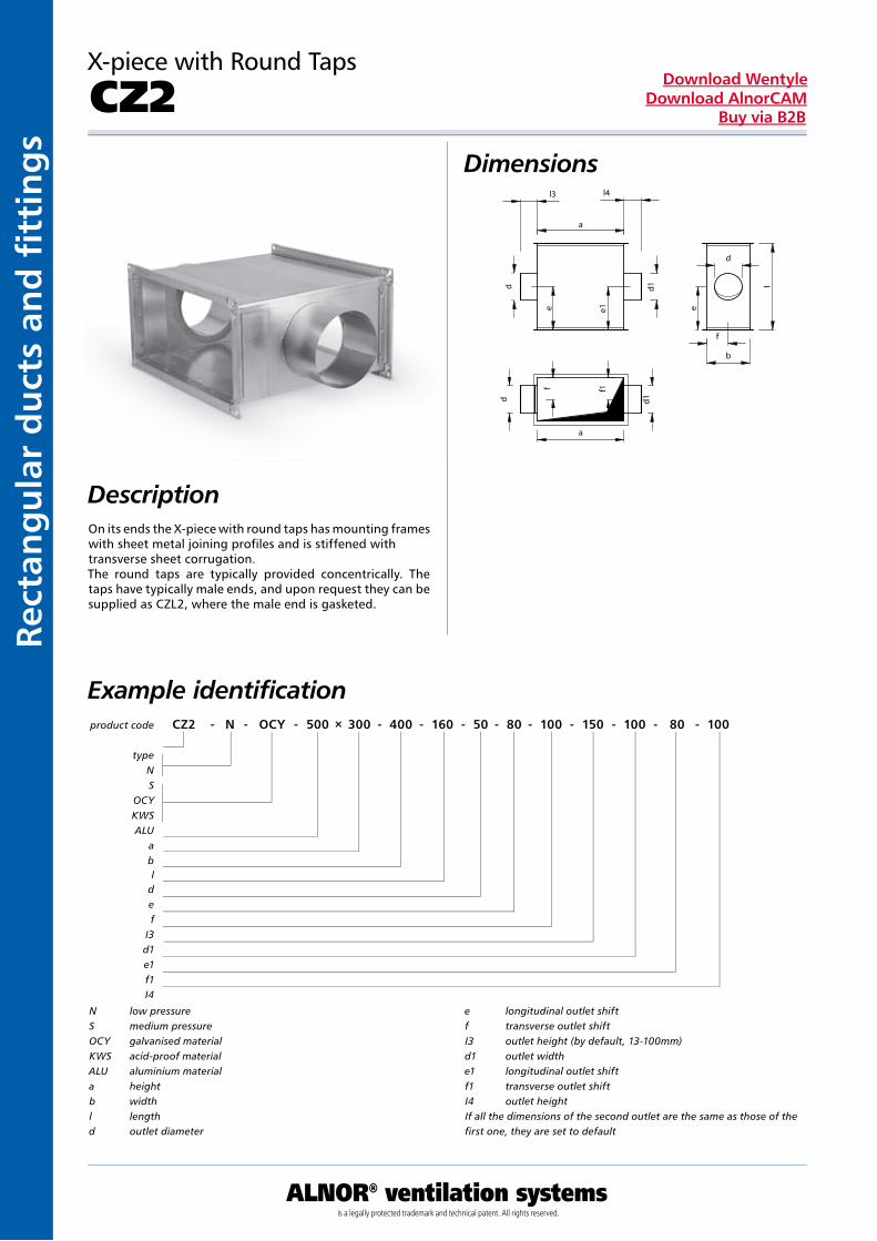
DescriptionOn its ends the X-piece with round taps has mounting frames with sheet metal joining profiles and is stiffened with transverse sheet corrugation.The round taps are typically provided concentrically. The taps have typically male ends, and upon request they can be supplied as CZL2, where the male end is gasketed.
Example identificationproduct code CZ2 - N - OCY - 500 × 300 - 400 - 160 - 50 - 80 - 100 - 150 - 100 - 80 - 100
typeNS
OCYKWSALU
abl
def
I3d1e1f1I4
N low pressureS medium pressureOCY galvanised materialKWS acid-proof materialALU aluminium materiala heightb widthl lengthd outlet diameter
e longitudinal outlet shiftf transverse outlet shiftI3 outlet height (by default, 13-100mm)d1 outlet widthe1 longitudinal outlet shiftf1 transverse outlet shiftI4 outlet heightIf all the dimensions of the second outlet are the same as those of the first one, they are set to default
ALNOR® ventilation systemsis a legally protected trademark and technical patent. All rights reserved.
Rectang
ular d
ucts an
d fi ttin
gs
Download WentyleDownload AlnorCAM
Buy via B2B
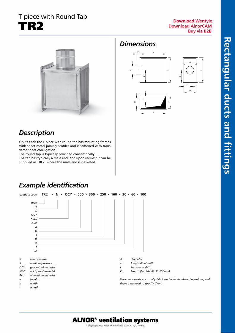
T-piece with Round Tap
TR2Dimensions
DescriptionOn its ends the T-piece with round tap has mounting frames with sheet metal joining profiles and is stiffened with trans-verse sheet corrugation.The round tap is typically provided concentrically. The tap has typically a male end, and upon request it can be supplied as TRL2, where the male end is gasketed.
Example identificationproduct code TR2 - N - OCY - 500 × 300 - 250 - 160 - 30 - 60 - 100
typeNS
OCYKWSALU
abl
def
I3
N low pressureS medium pressureOCY galvanised materialKWS acid-proof materialALU aluminium materiala heightb widthl length
d diametere longitudinal shiftf transverse shiftI3 length (by default, 13-100mm)
The components are usually fabricated with standard dimensions, and there is no need to specify them.
Kan
ały
i ksz
tałt
ki p
rost
oką
tne
ALNOR® ventilation systemsis a legally protected trademark and technical patent. All rights reserved.
Rect
ang
ula
r d
uct
s an
d fi
tti
ng
sDownload Wentyle
Download AlnorCAMBuy via B2B
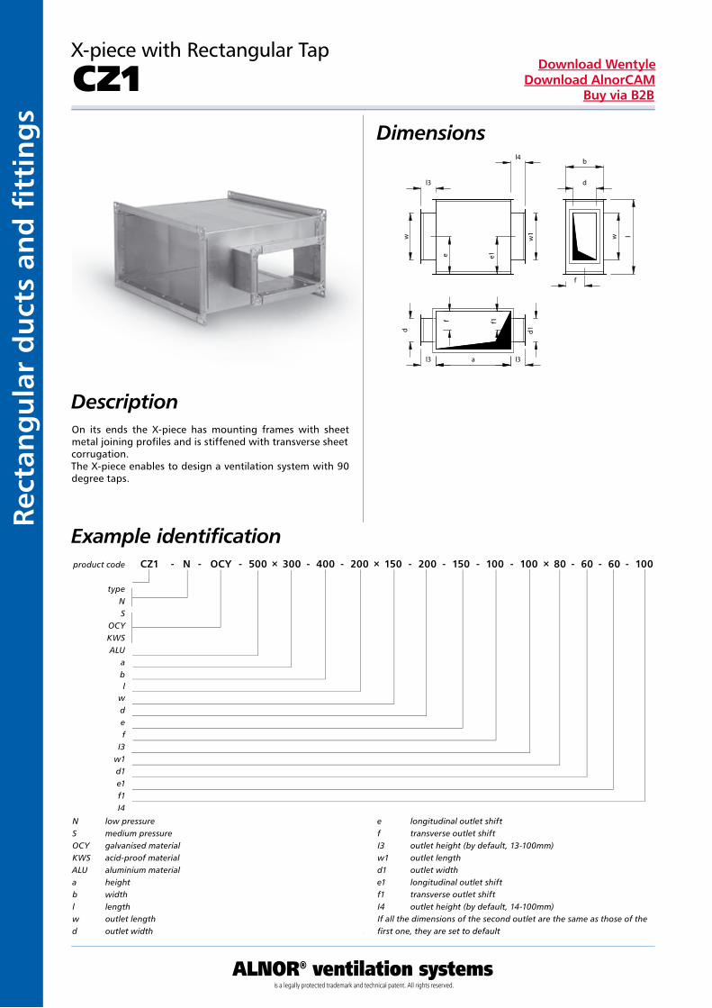
X-piece with Rectangular Tap
CZ1Dimensions
DescriptionOn its ends the X-piece has mounting frames with sheet metal joining profiles and is stiffened with transverse sheet corrugation. The X-piece enables to design a ventilation system with 90 degree taps.
Example identificationproduct code CZ1 - N - OCY - 500 × 300 - 400 - 200 × 150 - 200 - 150 - 100 - 100 × 80 - 60 - 60 - 100
typeNS
OCYKWSALU
abl
wdef
I3w1d1e1f1I4
N low pressureS medium pressureOCY galvanised materialKWS acid-proof materialALU aluminium materiala heightb widthl lengthw outlet lengthd outlet width
e longitudinal outlet shiftf transverse outlet shiftI3 outlet height (by default, 13-100mm)w1 outlet lengthd1 outlet widthe1 longitudinal outlet shiftf1 transverse outlet shiftI4 outlet height (by default, 14-100mm)If all the dimensions of the second outlet are the same as those of the first one, they are set to default
ALNOR® ventilation systemsis a legally protected trademark and technical patent. All rights reserved.
Rectang
ular d
ucts an
d fi ttin
gs
Download WentyleDownload AlnorCAM
Buy via B2B
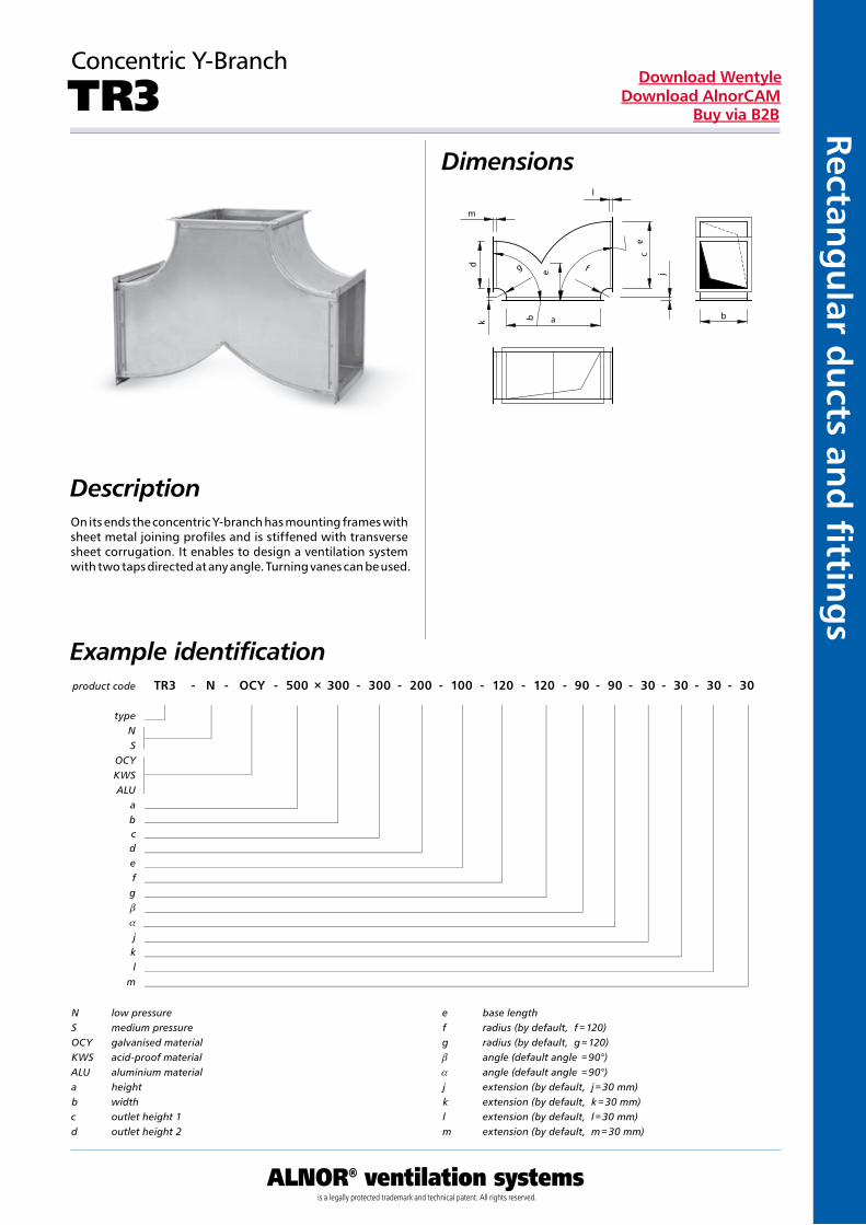
Concentric Y-Branch
TR3Dimensions
DescriptionOn its ends the concentric Y-branch has mounting frames with sheet metal joining profiles and is stiffened with transverse sheet corrugation. It enables to design a ventilation system with two taps directed at any angle. Turning vanes can be used.
Example identificationproduct code TR3 - N - OCY - 500 × 300 - 300 - 200 - 100 - 120 - 120 - 90 - 90 - 30 - 30 - 30 - 30
typeNS
OCYKWSALU
abcdefgb
a
jkl
m
N low pressureS medium pressureOCY galvanised materialKWS acid-proof materialALU aluminium materiala heightb widthc outlet height 1d outlet height 2
e base lengthf radius (by default, f = 120)g radius (by default, g = 120)b angle (default angle = 90°)a angle (default angle = 90°)j extension (by default, j = 30 mm)k extension (by default, k = 30 mm)l extension (by default, l = 30 mm)m extension (by default, m = 30 mm)
Kan
ały
i ksz
tałt
ki p
rost
oką
tne
ALNOR® ventilation systemsis a legally protected trademark and technical patent. All rights reserved.
Rect
ang
ula
r d
uct
s an
d fi
tti
ng
sDownload Wentyle
Download AlnorCAMBuy via B2B
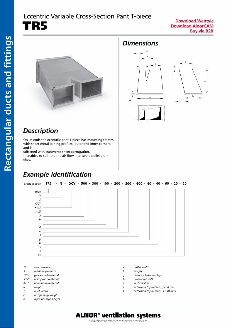
Eccentric Variable Cross-Section Pant T-piece
TR5Dimensions
DescriptionOn its ends the eccentric pant T-piece has mounting frames with sheet metal joining profiles, outer and inner corners, and is stiffened with transverse sheet corrugation. It enables to split the the air flow into two parallel bran-ches.
Example identificationproduct code TR5 - N - OCY - 500 × 300 - 100 - 200 - 200 - 600 - 60 - 40 - 60 - 20 - 20
typeNS
OCYKWSALU
abcdel
ghij
kv
N low pressureS medium pressureOCY galvanised materialKWS acid-proof materialALU aluminium materiala heightb inlet widthc left passage heightd right passage height
e outlet widthl lengthg distance between tapsh horizontal shifti vertical shiftj extension (by default, j = 30 mm)k extension (by default, k = 30 mm)
ALNOR® ventilation systemsis a legally protected trademark and technical patent. All rights reserved.
Rectang
ular d
ucts an
d fi ttin
gs
Download WentyleDownload AlnorCAM
Buy via B2B
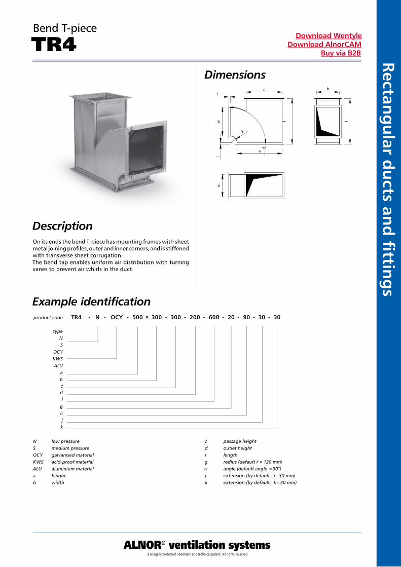
Bend T-piece
TR4Dimensions
DescriptionOn its ends the bend T-piece has mounting frames with sheet metal joining profiles, outer and inner corners, and is stiffened with transverse sheet corrugation. The bend tap enables uniform air distribution with turning vanes to prevent air whirls in the duct.
Example identificationproduct code TR4 - N - OCY - 500 × 300 - 300 - 200 - 600 - 20 - 90 - 30 - 30
typeNS
OCYKWSALU
abcdl
ga
jk
N low pressureS medium pressureOCY galvanised materialKWS acid-proof materialALU aluminium materiala heightb width
c passage heightd outlet heightl lengthg radius (default r = 120 mm)a angle (default angle = 90°) j extension (by default, j = 30 mm)k extension (by default, k = 30 mm)
Kan
ały
i ksz
tałt
ki p
rost
oką
tne
ALNOR® ventilation systemsis a legally protected trademark and technical patent. All rights reserved.
Rect
ang
ula
r d
uct
s an
d fi
tti
ng
sDownload Wentyle
Download AlnorCAMBuy via B2B
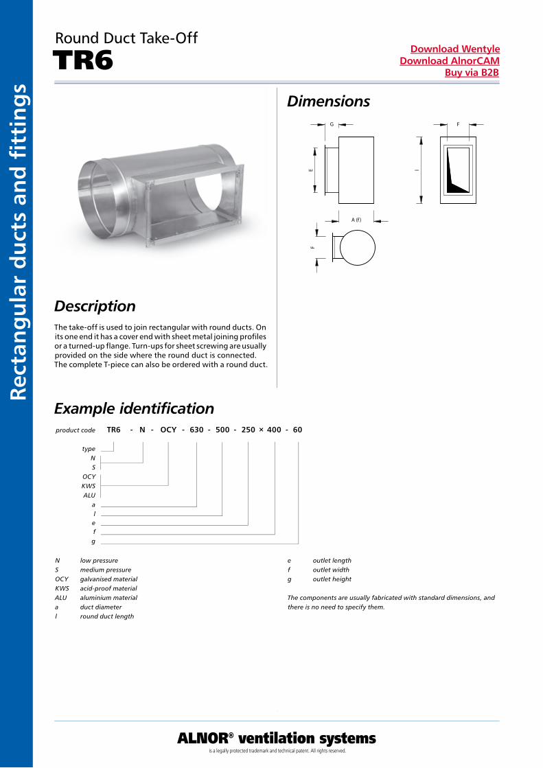
Round Duct Take-Off
TR6Dimensions
DescriptionThe take-off is used to join rectangular with round ducts. On its one end it has a cover end with sheet metal joining profiles or a turned-up flange. Turn-ups for sheet screwing are usually provided on the side where the round duct is connected. The complete T-piece can also be ordered with a round duct.
Example identificationproduct code TR6 - N - OCY - 630 - 500 - 250 × 400 - 60
typeNS
OCYKWSALU
alefg
N low pressureS medium pressureOCY galvanised materialKWS acid-proof materialALU aluminium materiala duct diameterl round duct length
e outlet lengthf outlet widthg outlet height
The components are usually fabricated with standard dimensions, and there is no need to specify them.
lE
G F
A (f )
F
ALNOR® ventilation systemsis a legally protected trademark and technical patent. All rights reserved.
Rectang
ular d
ucts an
d fi ttin
gs
Download WentyleDownload AlnorCAM
Buy via B2B
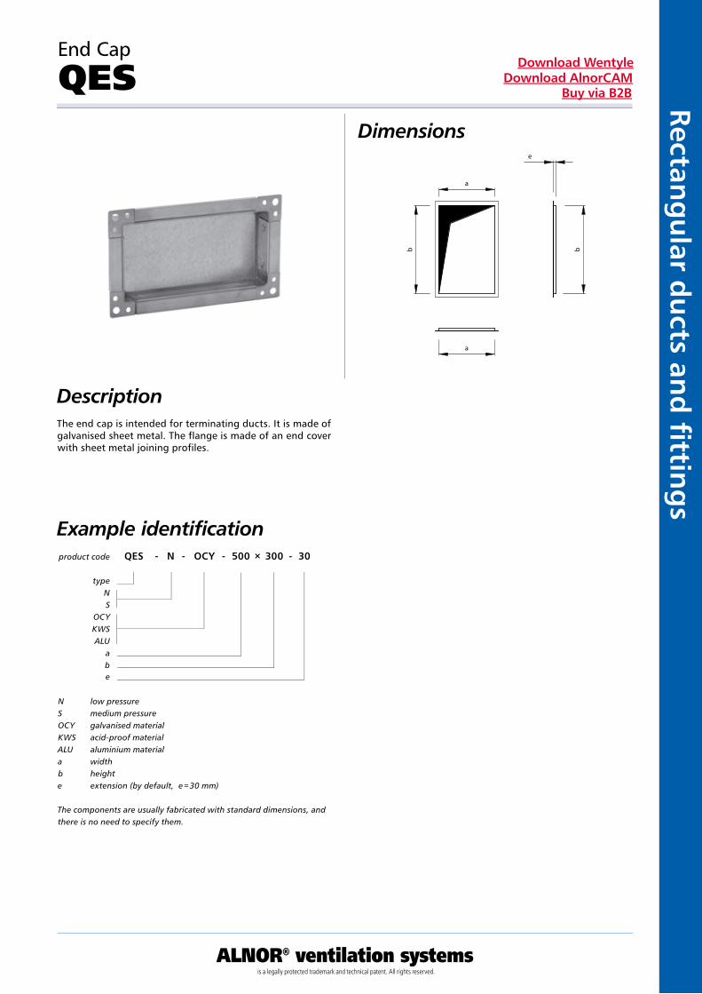
End Cap
QES Dimensions
DescriptionThe end cap is intended for terminating ducts. It is made of galvanised sheet metal. The flange is made of an end cover with sheet metal joining profiles.
Example identification
N low pressureS medium pressureOCY galvanised materialKWS acid-proof materialALU aluminium materiala widthb heighte extension (by default, e = 30 mm)
The components are usually fabricated with standard dimensions, and there is no need to specify them.
product code QES - N - OCY - 500 × 300 - 30
typeNS
OCYKWSALU
abe