Finishing Plasterboard - siniat.com.au
18
Finishing Plasterboard
Transcript of Finishing Plasterboard - siniat.com.au
Finishing Plasterboard
Technical Advice 1300 724 505 knaufplasterboard.com.au 345
4.1 Levels of Finish 346Australian Standard Requirements 346Level 3 Finish 347Level 4 Finish 347Level 5 Finish 347
4.2 Back-Blocking 348Back-Blocking Requirements 349Back-Blocking Ceiling Recessed Joints 349Back-Blocking Butt Joints on Ceilings and Walls 350
4.3 Jointing Plasterboard 352Compounds 353Three Coat Jointing System 354Internal and External Corners 355 4.4 Cornice Installation 356Cornice Installation 356
4.5 Painting Plasterboard 358Australian Standard Requirements 358Sealer Undercoat Application 359Paint Application 359Inspection 359
4.6 Glancing Light 360Minimising Glancing Light 361
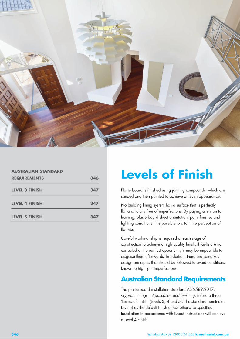
Levels of FinishPlasterboard is finished using jointing compounds, which are sanded and then painted to achieve an even appearance.
No building lining system has a surface that is perfectly flat and totally free of imperfections. By paying attention to framing, plasterboard sheet orientation, paint finishes and lighting conditions, it is possible to attain the perception of flatness.
Careful workmanship is required at each stage of construction to achieve a high quality finish. If faults are not corrected at the earliest opportunity it may be impossible to disguise them afterwards. In addition, there are some key design principles that should be followed to avoid conditions known to highlight imperfections.
Australian Standard RequirementsThe plasterboard installation standard AS 2589:2017, Gypsum linings – Application and finishing, refers to three ‘Levels of Finish’ (Levels 3, 4 and 5). The standard nominates Level 4 as the default finish unless otherwise specified. Installation in accordance with Knauf instructions will achieve a Level 4 Finish.
346 Technical Advice 1300 724 505 knaufmetal.com.au
AUSTRALIAN STANDARD
REQUIREMENTS 346
LEVEL 3 FINISH 347
LEVEL 4 FINISH 347
LEVEL 5 FINISH 347

Technical Advice 1300 724 505 knaufplasterboard.com.au 347
LEVELS OF FINISH 4.1
FRAMING REQUIREMENTS FOR EACH LEVEL OF FINISH
Australian Standard 2589 defines allowable deviations in the flatness of the framing surface to achieve the required level of finish. Framing members must have a minimum fixing face width of 32mm for screw fixing and 35mm for nail fixing. Framing should be true, plumb and level. Before installing plasterboard, the frame must be flat enough for the required level of finish. Over a 1.8m straight edge the frame must not deviate more than the values listed in Table 1.
Level 3 FinishA Level 3 Finish is recommended where no decoration is required such as walls above ceilings and concealed storage areas. The requirements for a Level 3 Finish are:
Framing as per the requirements in Table 1
A bedding coat and second coat on all face layer joints and corners.
Level 4 FinishLevel 4 is the default finish and is recommended for most applications when lighting is favourable and light colour, matt or low sheen paints are used. The requirements for a Level 4 Finish are:
Framing and back-blocking as per the requirements in Table 1
Face layer joints finished as detailed in Section 4.3 Three Coat Jointing System
A quality three coat paint system as detailed in Section 4.5 Painting Plasterboard.
Level 5 FinishA Level 5 Finish is the highest level of finish defined in the Australian Standard. Installation of the frame and plasterboard, finishing with compounds and the correct application of paint all contribute to a Level 5 Finish. Even if completed correctly, a Level 5 Finish may not result in all surface deviations being concealed, only minimised.
A Level 5 Finish is recommended where gloss, semi-gloss or dark colour paints are used, or in harsh or critical lighting conditions which are referred to as glancing light. Higher standards are required for frame flatness, jointing and back-blocking. It involves coating the entire wall or ceiling to provide an even surface texture and porosity, which helps conceal joints and fixing points. The coating may be sprayed, rolled or trowelled over the surface.
The requirements for a Level 5 Finish are:
Framing as per requirements in Table 1
Back-blocking of all ceiling joints and wall butt joints
Joints finished as detailed in Section 4.3 Three Coat Jointing System
Application of an additional coating over the entire surface to provide uniform texture and porosity
A quality three coat paint system as detailed in Section 4.5 Painting Plasterboard.
For a premium Level 4 Finish use OPAL. [Refer to the latest OPAL information on the website]
TABLE 1 Level of Finish Requirements for Non-Fire Rated Systems
Requirements Level 3 Level 4 Level 5
Back-block recessed joints on ceilings with 3 or more recessed joints Optional 1 Back-block recessed joints on ceilings with less than 3 recessed joints Optional Optional1 Ceiling butt joints permitted on framing members 2 2
Wall butt joints permitted on framing members 2 2
Minimum number of coats for jointing 2 3 3 and Skim Coat
Maximum frame deviation of 90% of area (mm)3 4 4 3
Maximum frame deviation of remaining area (mm)3 5 5 4
1 Back-blocking not required for recessed joints on suspended ceiling with no rigid connection at wall/ceiling junction.2 Back-blocking is required on these joints. [For more information, Refer to Section 4.2]3 Over a 1.8m straight edge the frame must not deviate by more than these values.

348
Back-BlockingBack-blocking is a method for reinforcing plasterboard joints to minimise joint cracking and peaking.
Back-blocked joints use strips of plasterboard adhered to the back of the joint between the framing members. Back-blocking adhesive must be set before commencing jointing.
348 Technical Advice 1300 724 505 knaufmetal.com.au
TABLE 2 Back-Blocking Requirements
Back-Blocking Required
Butt joints not made on a framing member Ceiling joints in balconies and breezeways Joints using MastaLite or MastaCoat3 for all three coats except those made over a framing member
Joints using self-adhesive fibreglass tape except those made over a framing member
Joints made over a framing member Multi-layer systems Wall butt joints less than 400mm in length and more than 2 metres above the floor
BACK-BLOCKING
REQUIREMENTS 349
BACK-BLOCKING CEILING
RECESSED JOINTS 349
BACK-BLOCKING BUTT
JOINTS ON CEILINGS
AND WALLS 350
BACK-BLOCKING 4.2
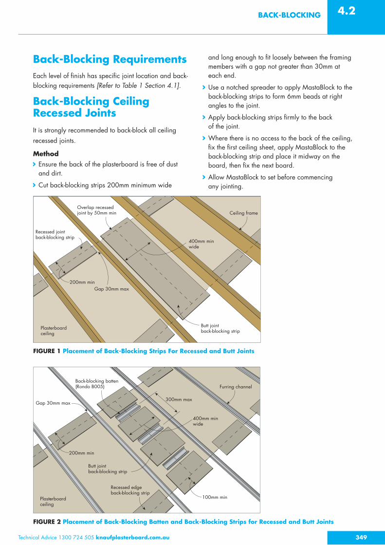
Back-Blocking RequirementsEach level of finish has specific joint location and back-blocking requirements [Refer to Table 1 Section 4.1].
Back-Blocking Ceiling Recessed JointsIt is strongly recommended to back-block all ceiling recessed joints.
Method Ensure the back of the plasterboard is free of dust and dirt.
Cut back-blocking strips 200mm minimum wide
and long enough to fit loosely between the framing members with a gap not greater than 30mm at each end.
Use a notched spreader to apply MastaBlock to the back-blocking strips to form 6mm beads at right angles to the joint.
Apply back-blocking strips firmly to the back of the joint.
Where there is no access to the back of the ceiling, fix the first ceiling sheet, apply MastaBlock to the back-blocking strip and place it midway on the board, then fix the next board.
Allow MastaBlock to set before commencing any jointing.
FIGURE 1 Placement of Back-Blocking Strips For Recessed and Butt Joints
200mm minGap 30mm max
400mm min wide
Ceiling frame
Plasterboard ceiling
Overlap recessed joint by 50mm min
Butt jointback-blocking strip
Recessed joint back-blocking strip
200mm min
100mm min
400mm min wide
300mm max
Furring channel
Plasterboard ceiling
Recessed edge back-blocking strip
Back-blocking batten (Rondo B005)
Butt joint back-blocking strip
Gap 30mm max
FIGURE 2 Placement of Back-Blocking Batten and Back-Blocking Strips for Recessed and Butt Joints
Technical Advice 1300 724 505 knaufplasterboard.com.au 349

Technical Advice 1300 724 505 knaufmetal.com.au350
4.2 BACK-BLOCKING
Back-Blocking Butt Joints on Ceilings and WallsButt joints are more difficult to conceal than recessed joints so they should be minimised. If butt joints are unavoidable, concealing them can be made easier by creating the joint mid-way between framing members, forming a recess and back-blocking. Butt joint requirements differ for each level of finish [Refer to Table 1 Section 4.1].
Method Create a recess by using either back-blocking battens as shown in Figure 3 or packers as shown in Figure 4 and 5.
Ensure the back of the plasterboard is free of dust and dirt.
Cut back-blocking strips 400mm minimun wide and long enough to fit loosely between
the framing members. Back-blocking strips are to overlap recessed joints by 50mm minimum.
Wall butt joints need support for the back-blocking strips as shown in Figure 5.
Use a notched spreader to apply MastaBlock to the back-blocking strips to form 6mm beads at right angles to the joint.
Apply back-blocking strips firmly to the back of the joint.
Where there is no access to the back of the ceiling, fix the first ceiling sheet. Apply MastaBlock to the back-blocking strip and place it midway on the board, then fix the next board.
Allow MastaBlock to set before commencing any jointing.
Where possible, avoid wall butt joints over single doors and cavity sliding doors to minimise joint cracking from vibration.

Back-blocking plasterboard strip
MastaBlock
Non-fire rated plasterboard
Ceiling butt joint with back-blocking plasterboard strip
Compound
Back-blocking plasterboard strip
MastaBlock
BattenButt joint with temporary batten and packer
Packer
Back-blocking plasterboard strip
MastaBlock
Non-fire rated plasterboard
Compound
Wall butt joint with back-blocking plasterboard strip
Back-blocking plasterboard strip
MastaBlock
BattenWall butt joint with temporary cleat and packer
Packer
Temporary laminating screws
Back-blocking batten (Rondo B0005)
Screws
Non-fire rated plasterboard
Butt joint with back-blocking battenCompound
Technical Advice 1300 724 505 knaufplasterboard.com.au 351
BACK-BLOCKING 4.2
FIGURE 3 Creating a Recess at Butt Joints Using Back-Blocking Battens – Elevation
FIGURE 4 Creating a Recess at a Butt Joint – Elevation
FIGURE 5 Creating a Recess at a Wall Butt Joint Using Laminating Screws – Plan View
352
Jointing PlasterboardPlasterboard walls and ceilings are jointed using compounds and reinforced with paper tape or corner beads.
All joints, internal and external corners and fastener heads must be evenly finished with compounds and lightly sanded to remove tool marks and ridges prior to decoration.
352 Technical Advice 1300 724 505 knaufmetal.com.au
COMPOUNDS 353
THREE COAT
JOINTING SYSTEM 354
INTERNAL AND
EXTERNAL CORNERS 355

CompoundsUse Knauf compounds with Knauf plasterboard systems. Performance of all systems in this guide rely on using nominated Knauf compounds. Use of non-Knauf compounds may reduce a system’s fire rating, appearance or other aspects of performance.
To achieve the FRL, fire rated systems require, as a minimum, paper tape and two coats of MastaBase/MastaLongset or three coats of MastaLite. Alternatively use Bindex Fire & Acoustic Sealant as permitted and detailed in the Bindex Technical Data Sheet. External fire rated wall systems with a moisture barrier wall wrap and non-combustible cladding covering the plasterboard do not require jointing.
Joints in wet areas must use paper tape. Areas to be tiled must only use MastaBase or MastaLongset.
Multi-layer systems only require face layer joints to be set, except GIB X-Block systems where all layers must be set.
There are two types of products used for jointing plasterboard: chemical setting compounds and air-drying compounds.
CHEMICAL SETTING COMPOUNDS
Chemical setting compounds are plaster based, supplied in powder form and when combined with water harden
by chemical reaction. They create the strongest joint.
Chemical setting compounds can be completely set but still damp. In cold and humid conditions, additional coats of chemical setting compounds can be applied to the joints when the compound is hard but before it is completely dry.
Hot and dry conditions may dry out the compound before it sets resulting in reduced strength and tape adhesion issues. Accelerating and retarding additives must not be used as they can also reduce strength.
Chemical setting compounds must not be applied over air-drying compounds.
AIR-DRYING COMPOUNDS
Air-drying compounds are premixed and harden by drying out. They are softer than chemical setting compounds, and are designed for easy sanding.
Previous coats of air-drying compound or chemical setting compounds must be completely dry before applying the next coat and before sanding. MastaTape Universal dries strong and is harder to sand.
In cold and humid conditions air-drying compounds may take longer to dry. Ventilation such as open windows or an exhaust fan may be required. Air-drying compounds must not be used in temperatures lower than 10°C.
TABLE 3 Type and Use of Finishing Compounds
Compounds Type Possible Compound Applications
Wet Areas Under Tiles
Fire Rated Systems
Bedding Second Finish
Bedding Cements
MastaBase Chemical setting powder MastaLongset Chemical setting powder Finishing Compounds
MastaFinish Air-drying premixed MastaGlide Air-drying premixed All Purpose Compounds
MastaLite Air-drying premixed MastaCoat3 Air-drying premixed MastaLine Air-drying premixed MastaTape Universal Air-drying premixed
Technical Advice 1300 724 505 knaufplasterboard.com.au 353
JOINTING PLASTERBOARD 4.3

Technical Advice 1300 724 505 knaufmetal.com.au354
4.3 JOINTING PLASTERBOARD
Three Coat Jointing SystemThe Three Coat Jointing System consists of a Bedding Coat, a Second Coat and a Finish Coat of compound. Level 4 Finish and Level 5 Finish must use the Three Coat Jointing System for all joints and external corners.
Internal corners only require a Bedding Coat and a Finish Coat.
BEDDING COAT (FIRST COAT)Method Fill any gaps more than 4mm at the joint and allow compound to set or dry
Using a 150mm broadknife, evenly fill the recess with compound [Refer to Figure 9 for minimum coat widths]
Place tape along the joint and bed it into the compound, removing excess compound and any air bubbles from behind the tape [Refer to Figures 6 & 7]
Apply a skim coat of compound over the tape [Refer to Figures 6 & 7].
SECOND COATMethod Allow the first coat of compound to set or dry
Use a 200mm trowel to apply a second coat of compound [Refer to Figures 8 and to Figure 9 for minimum coat widths]
Feather the joint edges to remove excess.
FIGURE 9 Minimum Coat Widths After Sanding
250mm
170mm
*
500mm
340mm240mm
Bedding Coat Bedding Coat
Second Coat Second Coat
Finish Coat Finish Coat
* Fill recess completelyRecessed Joint and back-blocked Butt Joints Butt Joint made over a framing member
FIGURES 6 & 7 Bedding Coat FIGURE 8 Second Coat
Paper tape is strongly recommended for all joints.
Joints made using paper tape are stronger and less prone to defects than those made with fibreglass tape. For the strongest joint, paper tape is recommended with two coats of MastaBase or MastaLongset and a final coat of MastaFinish, MastaGlide, MastaLite or MastaLine.
If fibreglass tape is used, all joints must be back-blocked. Fibreglass tape is not permitted for use in wet areas or fire rated systems.
Use broadknives, or a curved trowel for recessed joints and a flat trowel for butt joints on framing members.

Technical Advice 1300 724 505 knaufplasterboard.com.au 355
JOINTING PLASTERBOARD 4.3
FINISH COAT (THIRD COAT)Method Allow the second coat to set and dry. Lightly scrape off any lumps and high spots of compound
Use a 280mm trowel to apply a third coat of compound [Refer to Figure 10 and to Figure 9 for minimum coat widths]
Feather the joint edges to a smooth even surface, removing any excess
Allow the compound to fully dry before sanding.
FIGURE 10 Finish Coat
FASTENERS
Cover fastener heads with at least two coats of compound. Apply each coat in a different direction.
SANDINGMethod Lightly sand to a smooth even surface using a sanding float and 180 grit paper or 220 sanding mesh. Use finer paper for MastaLite (e.g. 220 paper) [Refer to Figure 11]
Do not expose or scuff the paper linerboard while sanding
Use power sanders with care as they can easily over sand the joint
A finished joint should have a slight crown.
FIGURE 11 Sanding
Internal CornersMethod Use a 75mm broadknife to apply compound to the corner
Fold paper tape in half and bed it into the compound using a corner taping tool
Cover the tape with a thin coat of bedding compound and remove any excess. Allow to set or dry
Apply a finish coat with a 100mm broadknife to both sides of the angle
Feather the edges and finish the joint with an internal angle finishing tool. Allow to dry
Lightly sand to a smooth finish before painting.
External CornersMethod Position a corner bead ensuring that it is plumb and straight [Refer to Figure 12]
Fix the bead in place using fasteners or staples at 300mm centres on both sides.
Treat external corner beads with the three coat jointing system as described previously. The minimum width of the three coats on both sides of the external corner is:
Bedding coat 200mm
Second coat 230mm
Finish coat 250mm.
300mm
FIGURE 12 Corner Bead on External Corner

Cornice InstallationCornice is used to complete the decoration of the building. Cornice is fixed to walls and ceilings using cornice cements, which are chemical setting compounds available in powder form.
Cornice cements are selected depending on the length and stability of the setting time, as well as their features for practical application, such as the ability to work back the cornice cement, polish mitres and the instant grab strength.
356 Technical Advice 1300 724 505 knaufmetal.com.au
CORNICE INSTALLATION 356

357357
FIGURE 16 Mitres
FIGURE 13 Butter Up
FIGURE 14 Position Cornice
FIGURE 15 Clean Off Excess
FIGURE 17 Wipe Down
TABLE 4 Type and Use of Compounds – Cornice Cements
Compounds Type Setting Time Applications
Minutes Cornicing Patching Jointing (1st and 2nd Coat)
Cornice Cements
MastaCove45 Chemical Setting Powder 45 MastaCove75 Chemical Setting Powder 75 MastaSmooth Chemical Setting Powder 45 3-in-1 Specialty Cement
MastaFix20 Chemical Setting Powder 20
Method
Ensure that wall and ceiling surfaces are free of dust and dirt
Measure and cut all cornices to the required lengths. Cut internal and external mitres using a mitre box
Avoid joints in straight runs where possible. If necessary, mitred joints are recommended
Measure and mark cornice projection on wall and ceiling to ensure accurate placement
Mix only the quantity of cornice cement that can be used within the setting time
Spread a 10mm continuous bead of cement along both back edges and the mitred end of the cornice [Figure 13]
Press the cornice into place and if necessary hold with temporary nails in the wall and ceiling along the edges of the cornice [Figure 14]
Clean off excess and remove nails when cement has partially set [Figure 15]
Straight stop along cornice edge at wall and ceiling. Finish mitres using a small cornice tool [Figure 16]
Wipe down the cornice with a wet sponge [Figure 17].
Technical Advice 1300 724 505 knaufplasterboard.com.au 357
CORNICE INSTALLATION 4.4

Australian Standard Requirements
Painting systems and methods are detailed in Australian Standard AS/NZS 2311, Guide to the painting of buildings. If painting plasterboard, a Three Coat Paint System must be applied to achieve the best finish. This consists of a sealer undercoat followed by two top coats. Both the quality of the paint and how it is applied have a large effect on the finished appearance of the plasterboard. Two coat paint systems are not nominated by AS/NZS 2311 as they often do not meet the customer’s expectations by showing up joints through texture and sheen variations.
Painting Plasterboard
358 Technical Advice 1300 724 505 knaufmetal.com.au
AUSTRALIAN STANDARD
REQUIREMENTS 358
SEALER UNDERCOAT
APPLICATION 359
PAINT APPLICATION 359
INSPECTION 359

359359
Sealer Undercoat ApplicationRECOMMENDATIONS
Ensure surfaces are set and dry
Lightly sand any minor surface defects and brush down surfaces to remove dust
Apply a sealer undercoat suitable for plasterboard, preferably with a roller. Plasterboard that has been exposed to sunlight and/or is discoloured will require a stain sealer undercoat
Ensure that the sealer undercoat is applied such that the plasterboard paper fibres remain flat
Check for any unsuitable surface imperfections and repair
Lightly sand with fine to medium grade paper before applying top coats
Avoid overworking sealer undercoat on plasterboard joints to avoid paint lifting.
Paint ApplicationRECOMMENDATIONS
Ensure surfaces are dry
Lightly sand any minor surface defects and brush down surfaces to remove dust
Cut in edges with a brush
Apply paint to the broad areas with an appropriate 10-14 mm nap synthetic roller. The roller nap gives a slight texture that improves the overall evenness of finish
Ensure each paint film is dry and manufacturer's recoat times are followed before applying the next coat.
If plasterboard is to be spray painted, the paint must not be diluted more than the manufacturer recommends. While the sealer undercoat is still wet, the surface should be back rolled to leave a ‘roller finish’. This helps to equalise the surface texture between the plasterboard and the set joints. For best results also back roll 2nd and 3rd coats. Any minor paint touch-ups can then be done with a roller rather than having to re-spray.
InspectionThe final inspection of a plasterboard wall or ceiling occurs after painting. AS/NZS 2589 AS/NZS 2311 recommend that visual inspection of finished surfaces of plasterboard be carried out in ordinary lighting, sighting from a distance of at least 1.5 metres from the surface. If differences of appearance are not clearly discernable the finish is usually considered acceptable.
To achieve a good quality painted finish, the following recommendations in addition to the three
coat paint system should be followed:
Apply paint according to the manufacturer’s recommendations
Avoid spraying or brushing which require advanced application techniques
Choose white or light colours, flats for ceilings and matt or low sheen paints for walls
Select a Level 5 Finish when using medium to high gloss or dark coloured paints, or in areas of glancing light in accordance with AS2589. These paints highlight any minor imperfections in the plasterboard and make the joints more visible.
For more information on glancing light, painting and other subjects affecting the appearance of plasterboard walls and ceilings, refer to:
www.awci.org.au (Association of Wall and Ceiling Industries – Australia and New Zealand)
www.apmf.asn.au (Australian Paint Manufacturers Association).
Technical Advice 1300 724 505 knaufplasterboard.com.au 359
PAINTING PLASTERBOARD 4.5

Glancing LightGlancing light is natural or artificial light that is cast along a surface. Glancing Light refers to light being cast along the face of a surface showing any minute undulation. As a result of this light being cast, a shadow is produced on the other side of the undulation. This draws attention to surface texture variations, such as plasterboard joints and patches, which under more diffused light would not be visible.
The glancing light condition can occur even when the wall or ceiling has been built according to AS/NZS 2589. Glancing light effects are directly linked to the type and placement of light sources relative to ceilings and walls.
MINIMISING
GLANCING LIGHT 361
360 Technical Advice 1300 724 505 knaufmetal.com.auTechnical Advice 1300 724 505 knaufmetal.com.au
Glancing light can highlight the following surface conditions:
Sheet joints
Surface irregularities
Patches
Variations in paint application technique.
Attention can also be drawn to minor deviations inherent in the manufacture and installation of plasterboard.
Minimising Glancing LightINTERIOR DESIGN
The following are recommendations to reduce the effect of glancing light:
Avoid full length windows in direct sunlight
Avoid locating windows close to perpendicular wall and ceiling surfaces during design phase
Diffuse light entering a room by using curtains, blinds or other window treatments
Introduce curtains or blinds where windows are close to wall and ceiling surfaces
Use low gloss, light coloured paints applied with a brush or roller.
FRAMING
Framing members should be straight and aligned.
SHEET ORIENTATION
Plasterboard sheets should be fixed parallel to the light source. Also arrange the sheets to minimise the number of joints.
LIGHTING
Glancing light caused by artificial lighting can be addressed by changing the type and/or positioning of the light fittings. Natural lighting problems are normally caused by building geometry. An example is running windows right to the edge of the ceiling or wall line.
The following are recommendations for design of light fittings:
Use recessed downlights and recessed fluorescent tubes
Shade batten-fixed bulbs on the ceiling and table lamps
Avoid designs that will create glancing light conditions where possible
Position downlights so that they do not shine down the surface of a wall.
For a premium Level 4 Finish use OPAL [Refer to the latest OPAL brochure on the website].
LEVEL 5 FINISH
A Level 5 Finish is the highest level of finish possible and can assist in reducing the effect of glancing light. By covering the entire surface, the skim coat of a Level 5 Finish fills any slight impressions in the surface, and removes the difference in texture and paint absorption between plasterboard and the joints. The framer, plasterer and painter all need to cooperate and contribute to providing a Level 5 Finish. Even when applied correctly, a Level 5 Finish is no guarantee that all surface deviations will be invisible, only minimised [Refer to Section 4.1 for details on Level 5 Finish].
Technical Advice 1300 724 505 knaufplasterboard.com.au 361
GLANCING LIGHT 4.6