FINAL TECHNICAL REPORT - 熱流計の専門商社|テ … TECHNICAL REPORT ADVANCED THERMOELECTRIC...
178
PPG Industries, Inc. Award No. DE-FC36-04GO14044 - 1 - FINAL TECHNICAL REPORT ADVANCED THERMOELECTRIC MATERIALS FOR EFFICIENT WASTE HEAT RECOVERY IN PROCESS INDUSTRIES DOE AWARD DE-FC36-04GO14044 PROJECT PERIOD 7/2004 – 6/2008 PRINCIPAL INVESTIGATORS: Adam Polcyn (412)820-4918 [email protected] Moe Khaleel (509)375-2438 [email protected] RECIPIENT ORGANIZATION: PPG Industries, Inc. One PPG Place Pittsburgh, PA 15272 PROJECT TEAM MEMBER ORGANIZATIONS: Pacific Northwest National Laboratory Dr. John Johnson Owens-Illinois 30 September, 2008
Transcript of FINAL TECHNICAL REPORT - 熱流計の専門商社|テ … TECHNICAL REPORT ADVANCED THERMOELECTRIC...
PPG Industries, Inc. Award No. DE-FC36-04GO14044
- 1 -
FINAL TECHNICAL REPORT
ADVANCED THERMOELECTRIC MATERIALS FOR
EFFICIENT WASTE HEAT RECOVERY IN PROCESS
INDUSTRIES
DOE AWARD DE-FC36-04GO14044
PROJECT PERIOD 7/2004 – 6/2008
PRINCIPAL INVESTIGATORS:
Adam Polcyn (412)820-4918
Moe Khaleel (509)375-2438
RECIPIENT ORGANIZATION:
PPG Industries, Inc. One PPG Place
Pittsburgh, PA 15272
PROJECT TEAM MEMBER ORGANIZATIONS:
Pacific Northwest National Laboratory Dr. John Johnson
Owens-Illinois
30 September, 2008

PPG Industries, Inc. Award No. DE-FC36-04GO14044
- 2 -
Acknowledgement: This report is based upon work supported by the U.S. Department of Energy under Award No. DE-FC36-04GO14044. Disclaimer: Any findings, opinions, and conclusions or recommendations expressed in this report are those of the author(s) and do not necessarily reflect the views of the Department of Energy. Proprietary Data Notice: There is no proprietary data in this report.

PPG Industries, Inc. Award No. DE-FC36-04GO14044
- 3 -
Table of Contents Table of Contents 3 List of Acronyms 4 List of Figures 5 List of Tables 8 List of Appendices 9 Executive Summary 10 Introduction 13 Background 15
TE Technology 15 Industrial Waste Heat Recovery 17
Results and Discussion 25 Advanced Thermoelectric Materials Development 25
Thermoelement Fabrication from Sputtered Material on Polyimide 26 Development of P-Type Material by Co-Sputtering AgSbTe2 and GeTe 27 Evolution of Materials Development 28 Development of N-Type Material by Co-Sputtering Ag and PbTe 31 Advanced TE Element Fabrication 32 Characterization of Thermoelectric Properties of Materials 34 TEG Fabrication 41
Industrial Waste Heat Recovery with Thermoelectric Technology 42 Bench Test of Prototype TEG 42 Glass Furnace Exhaust Flue Characterization Experiments 44 Conversion Device and System Design 49 Initial Economic Analysis 54 Economic Analysis After In-Plant Trial 77 Characterization of Emission and Impact on Heat Transfer 78
Accomplishments 98 Conclusions 99 Recommendations 100 References 101

PPG Industries, Inc. Award No. DE-FC36-04GO14044
- 4 -
List of Acronyms TEG – Thermoelectric Generator TE – Thermoelectric PNNL - Pacific Northwest National Laboratory GAST - Germanium Silver Antimony Telluride thermoelectric material GTC – Glass Technology Center AGC – Asahi Glass Co. HFT – Heat Flux Transducer RUTDC – Right Uptank Downcomer RDTDC – Right Downtank Downcomer LDTDC – Left Downtank Downcomer

PPG Industries, Inc. Award No. DE-FC36-04GO14044
- 5 -
List of Figures Figure 1 Schematic of basic TE device. .......................................................................15 Figure 2 Ideal TE device efficiency as a function of TH-TC, for TC=400K. ...................16 Figure 3 Schematic of Siemens regenerative glass melter. ...........................................19 Figure 4 Cross sectional view of Siemens regenerative melter. ....................................19 Figure 5 Schematic of oxyfuel flat glass melter............................................................20 Figure 6 Proposed concept for harvesting waste heat from exhaust gas flue with TEGs.23 Figure 7 Concept for TEG submodule. ........................................................................24 Figure 8 Approach to fabricating a thermoelement using thin films deposited on polyimide. .....................................................................................................................26 Figure 9 Approach to co-sputtering AgSbTe2 and GeTe to form a film on a substrate supported by flat substrate. ............................................................................................27 Figure 10 Modified approach to depositing thin films on long strips of polyimide. The aperature prevents deposited material from impacting the substrate at extremely oblique angles. ...........................................................................................................................30 Figure 11 Electrical properties of GAST films grown with parameters tabulated in Table 2 and using the rotating wheel with an aperature............................................................31 Figure 12 Results for co-sputtered Ag – PbTe films on a flat substrate platform. .........31 Figure 13 Seebeck coefficient and electrical conductivity vs temperature for a film deposited by co-sputtering from GeTe and AgSbTe2 targets on glass.............................33 Figure 14 Illustration of TE film deposited on polyimide edges. ..................................34 Figure 15 Approach for measuring thermal conductivity of a TE film on polyimide. ...35 Figure 16 Measured thermal loss for a 2 mil Kapton sample and for 16 micron GAST film on Kapton. .............................................................................................................36 Figure 17 Estimated values of thermal conductivity for Sample 3C-S. .........................36 Figure 18 Electrical conductivity versus temperature for Sample 3C-S. .......................37 Figure 19 Seebeck coefficient versus temperature for Sample 3C-S. ............................37 Figure 20 Schematic arrangement of samples and heater for measuring thermal conductivity of thick TE films .......................................................................................38 Figure 21 Apparatus for measuring thermal conductivity of disc-shaped samples (thermal shield lowered) ................................................................................................39 Figure 22 Apparatus for measuring thermal conductivity of disc-shaped samples (thermal shield in normal operating position).................................................................40 Figure 23 PNNL test bed for evaluating thermoelectric generators under waste heat flows which simulate conditions in industry. .................................................................42 Figure 24 Cross section of converter with key parameters for determining the energy balance, and an illustration of the inserted mantle. .........................................................43 Figure 25 Flue temperature data from suction pyrometry experiments. The view is facing the outboard wall of the right exhaust flue. The section of flue labeled “UT” is the up-tank downcomer, while “DT” is the down-tank downcomer. ....................................44 Figure 26 Flue velocity with the damper in place, blocking roughly half of the flue cross-section..................................................................................................................47 Figure 27 Gas flow in the exhaust flue with damper in place........................................48 Figure 28 Proposed slipstream design for in-plant test. ................................................49

PPG Industries, Inc. Award No. DE-FC36-04GO14044
- 6 -
Figure 29 Exploded Schematic of Flat Plate TEG, Diverter and Window Port Adapter. 51 Figure 30 Boom module geometry, looking across the flue cross-section.....................51 Figure 31 Boom module geometry, looking down the length of the flue.......................52 Figure 32 Heat pipe module geometry, looking down the length of the flue. ................53 Figure 33 Top view of Materials Testing Spoon in configuration used for Run 1. In Run 0, insulation was also applied around the inlet and outlet pipes. .....................................58 Figure 34 Side view of Materials Testing Spoon in configuration used for Runs 0,1. Insulation is not shown in this drawing for clarity..........................................................59 Figure 35 Heat flux transducer voltage towards the end of run "plug 13 1". .................62 Figure 36 Internal temperature and gas stream temperature. Air flow to the spoon was started at 16:09. Cooling of the spoon due to air flow is apparent..................................63 Figure 37 Response of inlet and outlet air temperatures to introducton of air flow to the spoon at 16:09. ..............................................................................................................64 Figure 38 Response of Thermonetics HFT to introduction of air flow to the spoon at 16:09. The HFT was saturated from 16:09 through 17:28. ............................................64 Figure 39 Suction pyrometer data at in-plant test site versus time. ...............................67 Figure 40 Various temperatures measured on the suction pyrometer and Materials Testing Spoon. ..............................................................................................................69 Figure 41 HFT data from the combined suction pyrometer / Materials Testing Spoon experiment. ...................................................................................................................69 Figure 42 Basic schematic of the in-plant test design, looking down from above. ........71 Figure 43 Engineering drawing of heat pipe used for the in-plant test. .........................72 Figure 44 Drawing of in-plant test site. This view is looking downtank (i.e. in the direction of glass motion). The downcomer is shown to the left, with the heat pipe extending at an angle across the downcomer. The external support structure used to support the heat pipe and move it in and out of the flue is shown above and behind the man. ..............................................................................................................................73 Figure 45 Photograph of in-plant test site, showing overhead support bar (blue) and the support used to minimize stress to the heat pipe during installation (folded back, orange) by supporting the heat pipe from below. ........................................................................74 Figure 46 Electrical power output of TEG versus time during the in-plant trial. ...........75 Figure 47 Behavior of a number of different parameters during the initial fast drop in power during the in-plant trial. ......................................................................................76 Figure 48 Gradient spoon.............................................................................................79 Figure 49 Temperature variation of gradient spoon across plate. ..................................80 Figure 50 Oxyfuel melter diagram showing right uptank downcomer (RUTDC) and right downtank downcomer (RDTDC)...........................................................................81 Figure 51 Gradient spoon after removal from right connecting flue before cleaning with brush and scraping region between hot end and 6” from hot end....................................84 Figure 52 Gradient spoon after removal from right connecting flue and after cleaning with brush and scraping region between hot end and 6” from hot end. ...........................85 Figure 53 Gradient spoon just after removal from RDTDC 10 feet up..........................86 Figure 54 Gradient spoon removed from RDTDC 10 feet up, after cooling. .................86 Figure 55 Jumps in HFT reading upon stopping and restarting data collection. Also shown are large, slower changes in HFT reading that did not correlate with other sensor readings.........................................................................................................................89

PPG Industries, Inc. Award No. DE-FC36-04GO14044
- 7 -
Figure 56 Fit of data for conductance measurement with HFT heat flux.......................90 Figure 57 Fit of data for "conductance" measurement using difference between HFT temperature and internal temperature, which is proportional to heat flux........................91 Figure 58 Decline in heat flux through the spoon over the extended exposure, as measured by the difference between HFT and Internal thermocouple temperatures........92 Figure 59 Heat flux (less zero flow heat flux) as a function of time over 15 days of continuous exposure to the flue environment at the proposed in-plant test site. No drifts or steps are observed. ....................................................................................................94 Figure 60 Heat flux as a function of time as measured during Run 2. ...........................95

PPG Industries, Inc. Award No. DE-FC36-04GO14044
- 8 -
List of Tables Table 1 Estimate of waste heat that could be harvested with TE technology for various process industries. .........................................................................................................13 Table 2 Typical process parameters for co-sputtering...................................................28 Table 3 Typical composition of GAST TE material .....................................................28 Table 4 Characterization of GAST film and resulting TE element ................................32 Table 5 Sample case studies showing present value payback v generated power value. .55 Table 6 Gas stream temperatures achieved by plugging brick-sized holes on the down and uptank sides of the right downtank downcomer.......................................................60 Table 7 Summary of heat flux data taken on air-cooled spoon......................................61 Table 8 Gardon gage radiometer data...........................................................................65 Table 9 Data collected in first gradient spoon experiments. ..........................................81 Table 10 Results of second round of gradient spoon experiments. ................................83 Table 11 Data collected for conductance measurements. ..............................................90 Table 12 Readings on various sensors before and after deliberately dumping a large quantity of powder on the spoon. Changes are also computed.......................................91 Table 13 Conductance from flue environment to spoon, and quantity proportional to that conductance, as a function of exposure time. The “2 hr (after 12 day)” data were taken after cleaning particulate from the spoon after 12 day exposure and reinserting the spoon at the same location. ......................................................................................................93

PPG Industries, Inc. Award No. DE-FC36-04GO14044
- 9 -
List of Appendices
Appendix I Study of the Characteristics and Control of Sodium Sulfate Particulate Cake Formation on a Heat Pipe Used for Energy Recovery from the Exhaust Gas of a Glass Manufacturing Furnace

PPG Industries, Inc. Award No. DE-FC36-04GO14044
- 10 -
Executive Summary At the turn of the century, over 2 Quads of waste heat energy was generated in the United States by various industrial processes (glass, aluminum, steel, and chemical manufacturing to name a few). By recovering this waste heat and converting it to a more useful form of energy, e.g. electricity, industrial energy efficiency could be improved dramatically. Thermoelectric generators (TEGs), which directly convert heat to electricity using thermoelectric materials, are a promising technology platform for waste heat recovery because they are easy to operate and maintain, and can be easily modified and scaled for a wide variety of industrial applications. In the 1990’s, new thin-film and bulk thermoelectric materials were discovered that held the promise of dramatically increasing the historically poor efficiency of thermoelectric devices1. For the first time, it became conceivable that thermoelectric technology could be an economically viable method for waste heat recovery. This insight provided the motivation for this project. The overall objective of the project was to integrate advanced thermoelectric (TE) materials into a power generation device that can convert waste heat from an industrial process to electrical power with an efficiency approaching 20%. Our strategy was to build on the new discoveries in thin-film thermoelectric materials to develop suitable advanced TE materials, integrate these into a TEG, and demonstrate waste heat recovery with efficiency approaching 20% in an existing industrial process. To demonstrate the viability and flexibility of the technology, we also set out to design (at least on paper) a large-scale waste heat recovery system and to identify the system cost targets that would need to be met to make the technology economical for industrial use. In order to achieve device efficiencies of 20%, the dimensionless figure-of-merit (ZT) for the thermoelectric materials needed to reach 2 or greater. Several potential high-ZT material candidates were investigated by PNNL, and the highest value of ZT achieved was around 1.5 at 275°C. In addition, it was recognized that due to the geometry of thin film samples and the relative thermal conductances of thin films and the substrates on which they are deposited, it is not trivial to integrate such materials into a practical thermoelectric device. However, PNNL developed a technique by which thin film thermoelectric materials could be deposited on 1.2m strips of 2-mil thick Kapton substrates. These strips were wound spirally into mechanically strong cylinders that resemble and potentially could be substituted for the conventional p- and n-type elements currently being built into commercially available TEGs. In parallel with advanced TEG development, waste heat recovery was demonstrated in an existing industrial process using a commercially available TEG with efficiency of 5%. It was hoped that such a demonstration would provide insight into the challenges that would be faced in integrating advanced TEGs with an existing industrial process. The industrial process chosen was the glass melting process at PPG Industries’ oxyfuel-fired furnace at Meadville, PA. The largest accessible waste heat source in this process is the furnace’s combustion exhaust gas stream, so waste heat was recovered from this source.

PPG Industries, Inc. Award No. DE-FC36-04GO14044
- 11 -
Several preliminary investigations were performed in advance of the in-plant waste heat recovery demonstration. PNNL built a bench-scale apparatus to characterize the Global Thermoelectric Model 7120 TEG, which was the commercially available TEG chosen for the in-plant demonstration. PPG characterized the combustion exhaust gas stream of the oxyfuel-fired furnace, and found that convective heat transfer from the gas was poor due to the low gas stream velocity, leaving radiative heat transfer from the hot (3000°F) glass melt as the dominant heat transfer mechanism. This led the partners to consider alternative designs for waste heat recovery. After considering several alternative designs, the partners decided to couple the TEG to a large sodium heat pipe. Heat pipe technology provides a very efficient means of transferring heat over long distances, and made it possible to collect radiant heat from the gas stream and transfer it to the TEG, which was connected to the heat pipe just outside the exhaust flue wall at room temperature conditions. This arrangement made it convenient to operate and maintain the TEG, and suggested a waste heat recovery strategy in which waste heat collection was performed by a number of modular units, each of which had a waste heat collection device that was customized to the waste heat source and transferred the heat to a TEG that need not be customized for each waste heat source. In addition to being easily adapted to a variety of waste heat recovery scenarios, this strategy makes it possible to quickly incorporate waste heat recovery in existing industrial processes without interrupting the operation of the process. The heat pipe / TEG waste heat recovery module was operated in the exhaust gas stream at Meadville for 3 months. The TEG was operated near its peak electrical output at the beginning of this trial, but within a week of starting the trial electrical output dropped to about 50% of peak, and remained near this level for the balance of the trial. Some additional small, slow degradation in power output was observed, most of which could be reversed by periodic cleaning of the heat pipe surface. At least one reason for the power degradation observed in the in-plant demonstration was the presence of solid and liquid materials (“condensates”) that would condense on any surface placed in the stream. These condensates were studied and found to be typically sodium sulfate, a component of the batch material used to make glass, and (to a lesser extent) refractory material from the walls of the exhaust flue that melted and dripped down onto the surface. The thermal effects of these condensates on a surface placed in the exhaust stream were studied. It was found that the heat flux to this surface fell by 50% after 12 days’ exposure to the exhaust stream environment, and then leveled off. This drop in heat flux was correlated to the buildup of condensates on the surface. The heat flux could be restored to its initial value by removing the surface from the exhaust stream and cleaning off the white solid powder buildup with a soft brush. Literature-based research was performed by Dr. John Johnson to study the properties of sodium sulfate and methods to remove it from heat transfer surfaces in the gas stream. Finally, the economics of modular waste heat recovery were considered. Given current TEG costs and projected costs for heat pipes in high-volume production, a waste heat recovery system based on the module demonstrated at Meadville would not be

PPG Industries, Inc. Award No. DE-FC36-04GO14044
- 12 -
economical for adoption by industry, even if TEG efficiencies were near 100%. PNNL found some scenarios in which the system would be economical at lower efficiencies if the cost of heat collection and transfer to the TEG could be reduced to a fraction of the TEG cost, and if TEG costs per watt dropped by more than a factor of 10. As a result of this work, we have concluded that waste heat recovery using thermoelectric technology is far from ready for widespread adoption by industry. In spite of the recent progress in material efficiency, it is not clear that these improvements in efficiency are adequate. Also, even with continued progress in materials efficiency, it is not trivial to incorporate these new thin-film materials into practical thermoelectric devices. Finally, the challenge of collecting waste heat and transferring it to the TEG is at least as important as the challenge of improving the efficiency of the TEG itself, and more work needs to be done to find economical ways of meeting both challenges.
PPG Industries, Inc. Award No. DE-FC36-04GO14044
- 13 -
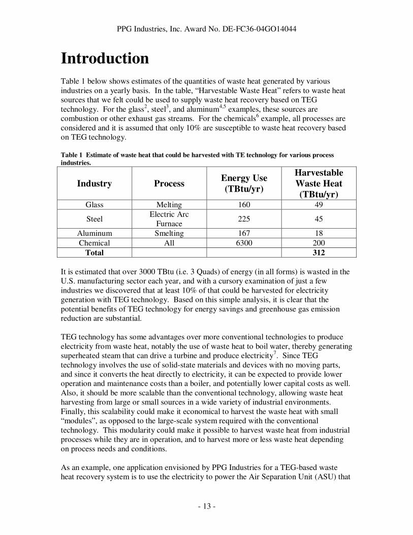
Introduction Table 1 below shows estimates of the quantities of waste heat generated by various industries on a yearly basis. In the table, “Harvestable Waste Heat” refers to waste heat sources that we felt could be used to supply waste heat recovery based on TEG technology. For the glass2, steel3, and aluminum4,5 examples, these sources are combustion or other exhaust gas streams. For the chemicals6 example, all processes are considered and it is assumed that only 10% are susceptible to waste heat recovery based on TEG technology. Table 1 Estimate of waste heat that could be harvested with TE technology for various process
industries.
Industry Process Energy Use
(TBtu/yr)
Harvestable
Waste Heat
(TBtu/yr) Glass Melting 160 49
Steel Electric Arc
Furnace 225 45
Aluminum Smelting 167 18 Chemical All 6300 200
Total 312
It is estimated that over 3000 TBtu (i.e. 3 Quads) of energy (in all forms) is wasted in the U.S. manufacturing sector each year, and with a cursory examination of just a few industries we discovered that at least 10% of that could be harvested for electricity generation with TEG technology. Based on this simple analysis, it is clear that the potential benefits of TEG technology for energy savings and greenhouse gas emission reduction are substantial. TEG technology has some advantages over more conventional technologies to produce electricity from waste heat, notably the use of waste heat to boil water, thereby generating superheated steam that can drive a turbine and produce electricity7. Since TEG technology involves the use of solid-state materials and devices with no moving parts, and since it converts the heat directly to electricity, it can be expected to provide lower operation and maintenance costs than a boiler, and potentially lower capital costs as well. Also, it should be more scalable than the conventional technology, allowing waste heat harvesting from large or small sources in a wide variety of industrial environments. Finally, this scalability could make it economical to harvest the waste heat with small “modules”, as opposed to the large-scale system required with the conventional technology. This modularity could make it possible to harvest waste heat from industrial processes while they are in operation, and to harvest more or less waste heat depending on process needs and conditions. As an example, one application envisioned by PPG Industries for a TEG-based waste heat recovery system is to use the electricity to power the Air Separation Unit (ASU) that

PPG Industries, Inc. Award No. DE-FC36-04GO14044
- 14 -
produces oxygen for use in an oxy-fuel glass furnace. The ASU requires roughly 3MW of electrical power, and the amount of power available in the form of heat in the combustion exhaust gas stream from the oxy-fuel furnace is approximately 20MW. Therefore, the method chosen to generate electricity from the exhaust gas stream must be at least 15% efficient. Note that this efficiency must consider both the efficiency of collecting and transferring the heat to the TEG, as well as the efficiency of the TEG itself. Typical efficiencies for commercially available TEGs that operate around 500°C (a relevant temperature for the oxy-fuel exhaust gas stream) are 5% or below. Also, commercial TEG costs are in the $5/W range, not considering the costs of the apparatus for collecting and transferring the heat to the TEG. Thus current TEG technology is not efficient enough to generate the amount of electricity needed for PPG’s application, nor is it expected to be cost-effective. The main challenge for improving the efficiency of TEG technology is improving the properties of the thermoelectric materials that convert the heat to electricity. TEG efficiency is directly related to the dimensionless figure-of-merit ZT, which are close to 0.5 in the temperature range of interest for commercial devices (despite intense work in the field beginning in the late 1930’s)8. As described below, ZT of 0.5 provides theoretical efficiencies, in the ideal case, of just under 10%. Given that real devices will not reach the theoretical efficiency (indeed, commercial devices apparently have efficiencies roughly half of the theoretical value), significant enhancement of ZT in the temperature range of interest is required. In 1993, Hicks and Dresselhaus9 published theoretical work that suggested that ZT could be increased by more than a factor of 10 for Bi2Te3 by considering quantum-confinement effects in a multilayer thin film structure. In 2001, Venkatasubramanian and his collaborators10 reported ZT of 2.4 at 300°K for Bi2Te3/Sb2Te3 superlattices. Also, Kanatzidis and his collaborators11 reported ZT of 2.2 at 500°C for AgPbmSbTe2+m bulk materials. These and other discoveries renewed interest in thermoelectric materials, and renewed hope that materials with high ZT at high temperatures could be realized. This project was motivated by the promising new results in TE material efficiencies, the capabilities at Pacific Northwest National Laboratory to further develop these materials, and the desire of PPG and other industrial partners to improve the energy efficiency of their manufacturing processes. We set out to develop the new thin film materials needed, to integrate them into a TEG device that could produce a modest amount of power, to design a device to capture heat and transfer it to the TEG efficienctly, and to demonstrate waste heat recovery with an efficiency near 20% in the combustion exhaust gas stream of PPG’s oxyfuel glass furnace.

PPG Industries, Inc. Award No. DE-FC36-04GO14044
- 15 -
Background
TE Technology The basic concept of TE energy conversion is illustrated in Figure 112. An n-type semiconductor material is electrically connected in series with a p-type semiconductor material, and the two are arranged so that a flow of heat through the elements will sustain a temperature gradient (TH – TC, where TH is the hot side temperature and TC the cold side temperature) across the elements. The temperature gradient causes electrons (in the n-type material) and holes (in the p-type material) to drift towards the heat sink, resulting in a flow of electrical current. The efficiency of the device is determined by TH – TC, and the figure of merit Z. Z is a property of the thermoelectric materials, equal to the square of the Seebeck coefficient, multiplied by the electrical conductivity, and divided by the thermal conductivity. Typically efficiency is described in terms of ZT, which is a dimensionless figure-of-merit equal to Z times the average of TH and TC. The dependence of the ideal, optimized efficiency of the TE device on temperature difference and ZT is described by the equation below and plotted in Figure 2.12
Figure 1 Schematic of basic TE device.

PPG Industries, Inc. Award No. DE-FC36-04GO14044
- 16 -
HCH
CH
TTZT
ZT
TTT
++
−+
−=
1
11η
0
5
10
15
20
25
30
35
40
0 200 400 600 800
Temperature Difference (K)
TE
De
vic
e E
ffic
ien
cy
(%
)
ZT=0.5
ZT=1
ZT=2
ZT=5
Tc=400K
Figure 2 Ideal TE device efficiency as a function of TH-TC, for TC=400K.
While there is no theoretical thermodynamic limit on ZT, typical state-of-the-art ZT values are close to 1 at temperatures relevant for industrial waste heat recovery (300C and above), which limits TEG efficiencies to less than 15%. As Hicks and Dresselhaus point out9, for simple materials an increase in Seebeck coefficient is accompanied by a decrease in electrical conductivity. Moreover, an increase in electrical conductivity leads to an increase in the electronic component of thermal conductivity. Thus only quite unique, semiconducting materials and/or unique configurations of those materials (such as multilayer thin film structures) have found some success as thermoelectric materials. For the waste heat recovery application considered in this project, Tc≈40°C and TH≈500°C. Thus the ZT value at 270°C is needed to estimate the performance of a given material in this application. A traditional material such as PbTe has ZT near 0.8 at 270°C, which (from Figure 2) gives a theoretical efficiency below 10%. In the 1990’s, a new class of bulk materials known as skutterudites were investigated13,14, with ZT’s in the 0.5-1.0 range near 270°C. In 2004, Kanatzidis and his collaborators at Michigan State University reported ZT of 1.5 near 270°C for AgPbmSbTe2+m.11 Chen et al.15 then reported that the (AgSbTe2)x(PbTe)(1-x) material showed multiphase behavior over the millimeter scale, leading to large inhomogeneities in Seebeck coefficient. A related material, TAGS, has ZT just above 1 and was used successfully for TEGs for many
PPG Industries, Inc. Award No. DE-FC36-04GO14044
- 17 -
decades16. To our knowledge, the new Michigan State material has not been successfully integrated into a working device to date. As noted in the Introduction, ZT near 2 has been reported in multilayer thin film structures near room temperature. These discoveries motivated PNNL to examine Si/SiGe and B4C/B9C superlattice structures for TEGs and to attempt to scale up these thin film materials in order to produce sufficient quantities of material to generate significant amounts of electrical power. According to Figure 2, and given that current commercial devices operate at efficiencies roughly half of their theoretical values, a ZT above 5 might be required to obtain efficiencies near 20% near 270°C. While progress has been made recently on improving ZT, there are currently no substantiated claims of ZT significantly above 1 in the temperature range of interest.
Industrial Waste Heat Recovery TEG technology is by no means the only option available for waste heat recovery in an industrial context. For the purposes of this project and this section of the Report, we will limit our discussion of industrial waste heat recovery to the glass industry, and primarily to the flat glass industry, as this is the area of expertise of the prime industrial partner involved in this project (PPG Industries). Waste heat boilers have been studied and (in some cases) implemented for use in various glass manufacturing facilities, particularly in Europe, for many years17,18,19. The hot combustion exhaust gas is used to boil water to create steam, which can then be used for a number of purposes, including driving a turbine to generate electricity. Recently, an AGC flat glass furnace in the Netherlands demonstrated a system with 2.1MW electrical output capacity20. Also, a Heye Glas container glass furnace in Germany has operated a boiler-based system with a 1MW electrical output capacity since 199621. In addition to electricity generation, boiler systems can be used to operate fans or compressors, or to provide space heating7. There are additional potential uses for waste heat that have been considered and implemented in the glass industry. One is to preheat the combustion gases and/or fuel used to melt the batch22. Indeed, one of the key ideas of the Siemens regenerative melter, the most common melter technology used in the flat glass industry, is to use combustion exhaust gases to heat refractory checker packing material. This hot refractory is then used to pre-heat combustion air drawn in from the outside before mixing it with fuel to melt the batch. Another idea is to use the waste heat to pre-heat batch material before melting it. This is particularly useful in the container glass industry, where a high proportion of cullet (which will not be carried away by an exhaust gas stream blowing over it) is used in the batch material. There are 13 glass manufacturing facilities worldwide that use this technique, 9 of them in Germany23. PPG also used this technique in its P-10 process for flat glass manufacturing, a unique process that was developed and used exclusively by PPG from 1979 to 1998.

PPG Industries, Inc. Award No. DE-FC36-04GO14044
- 18 -
As mentioned in the Introduction, our initial target for TEG technology was waste heat recovery from the combustion exhaust gas stream of a flat glass oxyfuel fired furnace operated by PPG in Meadville, Pennsylvania. Unlike conventional Siemens regenerative glass melting technology, oxyfuel-fired glass melters currently have no mechanism for capturing and using the waste heat contained in the combustion exhaust gas stream. While the efficiency of oxyfuel-fired glass melters is already superior to that of Siemens regenerative melters, with effective waste heat recovery the efficiency could be much higher. To give the reader a better understanding of the oxyfuel process, it is important to first give an account of the Siemens regenerative process (Figure 3). In the Siemens process, ambient air is drawn into the furnace by fans. This air passes over hot refractory material, where it is preheated before being combined with natural gas and ignited to produce a high luminosity flame that extends over the surface of the molten glass, which is contained in a large tank and continuously fed with solid batch material from one end of the tank. The luminous flame heats and melts the batch material primarily via radiative heat transfer. The hot combustion gases are then exhausted through a port on the opposite side of the tank, where they flow over refractory material in order to preheat it. After ten to fifteen minutes, the direction of gas flow is reversed so that ambient air is drawn over the newly heated refractory material, and combustion gases exhausted over the (now cold) refractory on the opposite side to begin heating that refractory again in preparation for the next reversal. These refractories are known as “regenerators” (or “checkers”), and typically there are two stages of regenerator on each side of the melter. The exhaust flues in which the primary regenerators reside are known as “downcomers”, since they connect the glass melter (on the first floor of the factory) with the connecting flues (in the basement). For a cross-sectional view of the process looking down the length of the melter, see Figure 4. As noted above, waste heat recovery is built into the Siemens process. However, it is relatively inefficient because a large fraction of the waste heat is used to preheat non-combustible components of air (e.g. nitrogen).

PPG Industries, Inc. Award No. DE-FC36-04GO14044
- 19 -
Figure 3 Schematic of Siemens regenerative glass melter.
Figure 4 Cross sectional view of Siemens regenerative melter.
AIR FIREDAIR FIRED

PPG Industries, Inc. Award No. DE-FC36-04GO14044
- 20 -
In the case of the oxyfuel process (Figure 5), natural gas is combined with oxygen (made at a separate facility) to produce a more efficient combustion process. The oxyfuel process does not involve reversal of the gas flow direction; rather, flames are produced continuously on both sides of the furnace, and combustion exhaust gases flow into the flues on both sides of the furnace continuously. The refractory checker material is removed from the flue regenerator areas. Because the hot combustion gases can not be exhausted directly into the atmosphere, cool ambient air is deliberately aspirated into the flues to cool the gas before ejecting it. This is achieved by introducing holes into the downcomer walls. As noted above, nearly 20MW of power are lost in this way.
The oxyfuel exhaust gas stream has great potential as a waste heat source. The exhaust gases continuously exit the melter at 2600°F, with an energy density of 1.8 MMBTU/ft2/hr. In addition to the high temperature and energy density, the gas stream is quite stable. On the other hand, the gas stream velocity is quite low (a few feet per second, driven largely by the aspirated room air used to cool the gas), so convective heat transfer is likely to be poor without modifying the gas stream (for example, constricting the flue diameter to increase gas velocity). Also, the gas stream contains solid and liquid components that can collect on heat exchangers and reduce heat transfer over time. There are other potential waste heat sources in a flat glass melter. Heat is lost through the refractory walls and crown of the melter. In addition, heat is lost further downstream in the process through the annealing lehr (which cools the glass in a controlled manner in order to optimize the stress state of the glass). We chose to focus on the exhaust gas stream for this project because (1) it is the largest concentrated source of waste heat in the process, and (2) harvesting waste heat from the exhaust gas stream could profoundly impact the efficiency of oxyfuel melting and therefore glass melting in general.
Figure 5 Schematic of oxyfuel flat glass melter. Figure 5 Schematic of oxyfuel melter.
5000 °F
2600 °F
5000 °F
2600 °F
Figure 5 Schematic of oxyfuel flat glass melter.

PPG Industries, Inc. Award No. DE-FC36-04GO14044
- 21 -
The overall objective of the project was to integrate advanced thermoelectric (TE) materials into a power generation device that can convert waste heat from an industrial process to electrical power with an efficiency approaching 20%. In order to achieve this objective, we needed to: • develop advanced TE materials with sufficiently high ZT to enable a 20% efficient
TEG device • design a TEG device that would make efficient use of the new materials to achieve at
least 20% efficiency • produce the TE materials in sufficient quantity and build them into a TEG • develop a method to extract heat from an industrial waste heat stream and supply the
heat to the TEG • build and validate the necessary equipment to extract the heat and supply it to the TEG • demonstrate waste heat recovery and electricity generation at efficiency of 20% or
above for a significant amount of time In order to demonstrate efficient waste heat recovery over a significant amount of time (at least several weeks), we anticipated a need to understand the effects of gas stream condensates on heat transfer, and to develop solutions to counteract those effects. To lend practical perspective to the work and demonstrate its value, we also felt it was important to propose a design for a large-scale waste heat recovery system based on the TEG and waste heat recovery method we developed, and to evaluate the economic feasibility of the system for a real industrial application. Given this objective and the anticipated steps required to meet the objective, the project work was organized into four major Tasks: Task 1. Design Energy Conversion System Subtask 1.1. Conversion System Design Subtask 1.2. Economic Analysis Task 2. Advanced Thermoelectric Materials Development Subtask 2.1. Advanced TE Materials Fabrication Subtask 2.2. Characterization of Materials Task 3. Thermoelectric Generator Fabrication and Test Subtask 3.1. TEG Fabrication Subtask 3.2. Bench Test of Prototype TEG Subtask 3.3. Testing of TEG at PPG Task 4. Combustion Emission Optimization Subtask 4.1. Characterization of Emission and Heat Transfer Subtask 4.2. Strategies to Minimize Emissions Impact Task 1 addressed the design of a large-scale energy conversion system based on the work of Tasks 2 and 3, and the economic viability of such a system for a representative industrial user. Task 2 addressed the development of advanced TE materials with high ZT, and characterization of those materials to demonstrate the ZT and other important properties for TEG device performance. Task 3 addressed the design and assembly of a

PPG Industries, Inc. Award No. DE-FC36-04GO14044
- 22 -
prototype TEG with advanced materials, the testing of that prototype on a small scale in the lab, and finally the transfer of that prototype to an industrial partner (PPG) to demonstrate efficient heat-to-electricity conversion in a real industrial process. Included in Task 3 was the work to design and build an apparatus to extract heat from the industrial process and transfer it to the TEG. Finally, Task 4 addressed characterization of the chosen industrial process (in our case, the combustion exhaust gas stream of a glass furnace) to support the design of the heat extraction and transfer apparatus, as well as addressing how the negative effects of particulates and other condensates in the exhaust gas stream could be counteracted. The impact of the project on industrial energy usage in the U.S. is driven by the efficiency and cost of the TE waste heat recovery device. This is in turn driven by the thermoelectric materials (addressed in Task 2 and Subtask 3.1) and by how heat is transferred to them (addressed in Subtasks 3.2,3.3, and 4.1). Given PNNL’s expertise and capabilities for development of advanced TE materials and devices, it was natural for PNNL to focus on Task 2 and Subtask 3.1. Given PPG’s expertise and capabilities for characterizing the glass furnace and testing devices in an industrial environment, it was natural for PPG to focus on Subtasks 3.3 and 4.1. PNNL also had the capability and resources to address Subtask 3.2. Both PPG and PNNL contributed to Task 1, and Subtask 4.2 was contracted to Dr. John Johnson, who brought expertise in the area of combustion emissions that was not available at either PPG or PNNL. The initial strategy for waste heat recovery with thermoelectrics in the glass process environment was to build thermoelectric devices in the form of large area flat panels that could be inserted in the walls of the melter and the flues, and on the external surfaces of the annealing lehr (see Figure 6). Relatively small area flat panel TEGs (less than 1 square foot) are commercially available from a number of vendors (e.g. Marlow Industries, Hi-Z Technology). For example, Hi-Z’s HZ-20 TEG produces 19W of power in a 3”x3”x0.2” package at 450°F hot side temperature24. Our initial approach was to build 10cm x 10cm “submodules” that could be connected together to produce larger “modules” that would provide higher electrical output.

PPG Industries, Inc. Award No. DE-FC36-04GO14044
- 23 -
Figure 6 Proposed concept for harvesting waste heat from exhaust gas flue with TEGs.
A schematic of such a submodule is shown in Figure 7 in both side view and cross-section. The n-type and p-type film elements are 10-100 µm in thickness. Materials systems to be considered for the elements included Si/SiGe multilayers, B4C/B9C multilayers, and multilayers based on skutterudite materials. The films would be deposited on a coated metal substrate, with necessary masking to form n-type and p-type sections on the substrate. The coating on the substrate is designed to protect the underlying metal substrate from the high-temperature environment. Electrical interconnects are provided between n-type and p-type elements. One important issue with this design is ensuring that the thin films have sufficiently low thermal conductance so that a significant temperature difference can be maintained across the device. For film thickness of 10 µm, thermal conductivity (typical of thermoelectrics or glassy materials) of 0.01 W/cm/K, a heat flux of 2 kW/cm2 would be required to maintain a temperature difference of 200°C across the device. For comparison, the Hi-Z HZ-20 uses a heat flux of 10 W/cm2 with a temperature difference of 200°C and a device thickness of 0.5cm.

PPG Industries, Inc. Award No. DE-FC36-04GO14044
- 24 -
Figure 7 Concept for TEG submodule.

PPG Industries, Inc. Award No. DE-FC36-04GO14044
- 25 -
Results and Discussion The results are presented in terms of the two major areas of work on this project: thermoelectric materials development, and industrial waste heat recovery with thermoelectric technology. The thermoelectric materials development work is presented first. After presentation of a novel method to fabricate thermoelements using thin-film TE material, the development of the p-type GAST material is described. This is followed by a description n-type Ag-PbTe material development, details of thermoelement fabrication using these materials, and a description of the metrology work done to characterize the thermoelectric properties of the new materials. Finally, an account of our efforts to fabricate a TEG with the new materials is given. Within the industrial waste heat recovery section, the results of an initial bench-scale test of existing TEG technology by PNNL are presented first. Next, several experiments to characterize the thermodynamics and fluid dynamics of PPG’s oxyfuel glass melter exhaust flue are discussed. The bench-scale test and the flue characterization experiments drove our thinking on design options for the waste heat recovery device. These designs, and a preliminary economic analysis by PNNL based on these designs, are presented next. The culmination of the design work and characterization experiments was the in-plant test of existing TEG technology at PPG. After an account of the in-plant test, the results of experiments on condensates in the furnace exhaust are described, along with the results of the literature study on condensate formation and control in the furnace exhaust.
Advanced Thermoelectric Materials Development In early work, several sputtered thin-films were investigated as candidates for high ZT thermoelectric materials. Multi-layer Si/SiGe and B9C/B4C films on thin single crystal silicon substrates were studied initially, but abandoned due to need for high-temperature heat treatment and due to substrate fragility. PNNL proceeded to study n-type Ag-doped PbTe films and p-type AgSbTe2-GeTe (GAST) alloys, on Kapton substrates. Sputter deposition of thin films of thermoelectric material has shown promise for a low cost approach to developing TE materials with ZT values approaching 2.0. Sputtered thin films produced in this task achieved electrical characteristics that suggest ZT values of 2.0 or greater can be achieved. These thin film structures are polycrystalline, multi-layered nanostructures. Whereas quantum well film structures consist of single crystal layers 1 nm to 10 nm thick, the films produced in this project are polycrystalline nanostructures. The work led to three major advances: (1) Demonstration that TE material can be sputter deposited onto long strips of polyimide and then spooled into cylindrical thermoelements;
PPG Industries, Inc. Award No. DE-FC36-04GO14044
- 26 -
(2) Processes were developed for growing films of P-type thermoelectric material that exhibits very good thermoelectric properties in the temperature range of 400°K to 650°K by co-sputtering from GeTe and AgSbTe2 targets; (3) Procedures were also developed for growing films of N-type thermoelectric material that exhibits improved thermoelectric properties in the temperature range of 450°K to 650°K by co-sputtering from Ag and PbTe targets. Further details of these advances are given in the following sections.
Thermoelement Fabrication from Sputtered Material on
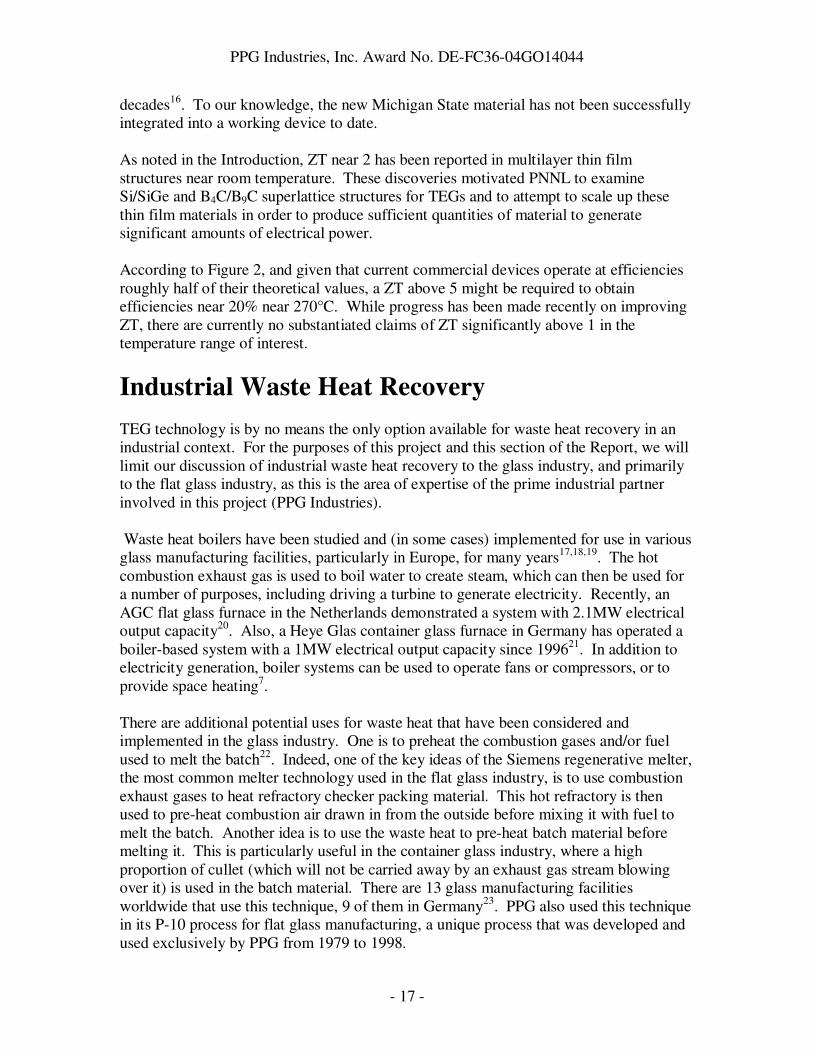
Polyimide An approach was developed allowing the fabrication of thermoelements that would be capable of being substituted for the cylindrical elements found in current commercial TEGs. This has been achieved by sputter depositing TE materials onto polyimide strips 1.2 meters long and spooling these strips into a tight, load-bearing cylindrical form. Deposition was carried out on a rotating wheel mounted in a sputtering chamber as depicted in Figure 8. The width and diameter of the wheel are 4.8 cm and 38 cm, respectively. Thermoelement fabrication was accomplished both by cutting strips from a 4.8 cm wide Kapton sample and by depositing directly onto pre-cut tapes 1 cm wide. After material deposition and spooling each strip into a cylindrical element, the ends of the element so formed were metalized.
Arrays of n- and p-type elements fabricated in this manner could be used to assemble a functional TEG. This procedure represents a unique and practical approach to utilizing
Figure 8 Approach to fabricating a thermoelement using thin films deposited on polyimide.
Sputtering Targets
TE Film
Deposition of TE Material On 1 meter Strip of Kapton
Long Strip Removed and Wound into Cylindrical Element
Metallization
PPG Industries, Inc. Award No. DE-FC36-04GO14044
- 27 -
thin films wherein the polyimide substrate acts as a scaffold to support a TE film that would not be capable of supporting itself. Efficient thermoelectric materials are characterized by thermal conductivities in the 0.01 to 0.02 Watts/cm/K range. Because the polyimide substrate material and thermoelectric film can be approximately the same thickness (10 to 20 µm), and the thermal conductivity of polyimide is an order of magnitude less (e.g., 0.001 W/cm/K with Kapton), the thermal conductivity of the polyimide substrate can be made to have a negligible impact on conversion efficiency. This approach was demonstrated with both n- and p-type materials.
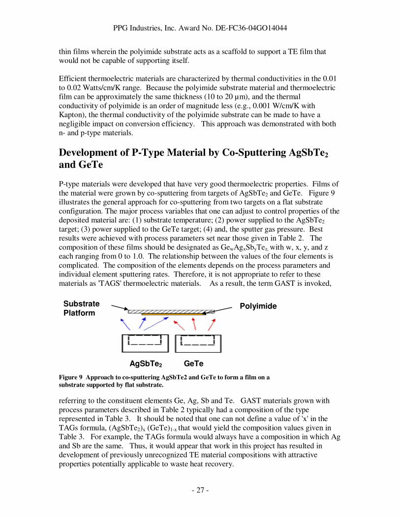
Development of P-Type Material by Co-Sputtering AgSbTe2
and GeTe P-type materials were developed that have very good thermoelectric properties. Films of the material were grown by co-sputtering from targets of AgSbTe2 and GeTe. Figure 9 illustrates the general approach for co-sputtering from two targets on a flat substrate configuration. The major process variables that one can adjust to control properties of the deposited material are: (1) substrate temperature; (2) power supplied to the AgSbTe2 target; (3) power supplied to the GeTe target; (4) and, the sputter gas pressure. Best results were achieved with process parameters set near those given in Table 2. The composition of these films should be designated as GewAgxSbyTez, with w, x, y, and z each ranging from 0 to 1.0. The relationship between the values of the four elements is complicated. The composition of the elements depends on the process parameters and individual element sputtering rates. Therefore, it is not appropriate to refer to these materials as 'TAGS' thermoelectric materials. As a result, the term GAST is invoked,
referring to the constituent elements Ge, Ag, Sb and Te. GAST materials grown with process parameters described in Table 2 typically had a composition of the type represented in Table 3. It should be noted that one can not define a value of 'x' in the TAGs formula, (AgSbTe2)x (GeTe)1-x that would yield the composition values given in Table 3. For example, the TAGs formula would always have a composition in which Ag and Sb are the same. Thus, it would appear that work in this project has resulted in development of previously unrecognized TE material compositions with attractive properties potentially applicable to waste heat recovery.
Figure 9 Approach to co-sputtering AgSbTe2 and GeTe to form a film on a
substrate supported by flat substrate.
Substrate Platform
Polyimide
AgSbTe2 GeTe

PPG Industries, Inc. Award No. DE-FC36-04GO14044
- 28 -
Table 2 Typical process parameters for co-sputtering
Substrate Sputtering Gas Power to Power to Temperature Pressure AgSbTe2 GeTe 330 ºC 3 mTorr 1.3 W/cm2 3.6 W/cm2 Table 3 Typical composition of GAST TE material
Ge 13.6 Atomic % Ag 1.5 Atomic % Sb 5.7 Atomic % Te 79.2 Atomic %
Evolution of Materials Development Prior to the initiation of this project, PNNL had investigated multi-layer film structures based on thin film Si/SiGe and B9C/B4C multi-layer structures. These films were grown on single crystal silicon substrates. As part of the previous effort, a sputtering system had been modified to allow automated growth of multi-layer films, where individual layers were from 25 Å to 100 Å thick. Initial studies carried out in the current project indicated that films deposited on insulating substrates are preferred over films deposited onto silicon. Work continued with the focus of growing and measuring the performance of advanced thick-film thermoelectric materials. The conceptual embodiment of these films was sputter depositing them on suitable thin metal substrates such as aluminum, copper and molybdenum. Using this geometry, functional thermoelements would be assembled by stacking the coated substrates one on top of the other and connected in electrical series. A number of samples were prepared that achieved adherent GAST depositions with thicknesses up to 12.5 µm. The thermoelectric properties of these samples were measured and reinforced earlier findings that the GAST composition possesses superior thermoelectric properties with the potential of exhibiting ZT values considerably greater than 1.0. Early development of GAST materials was conducted using the flat substrate configuration shown in Figure 9 which produced samples typically 25 mm wide and 75 mm long. Later in the project and because of potential difficulties in replicating thermoelectric properties and microstructure with bulk processing techniques, the bulk thermoelement path for materials fabrication was dropped and the focus returned to thin films. With existing equipment, 6-µm/hr sputter rates were achieved and 12-µm films of AgSbTe2/GeTe alloy produced for characterization. An important discovery applicable to industrial waste heat recovery resulted from experience gained in a different project that focuses on producing sputter-deposited TE

PPG Industries, Inc. Award No. DE-FC36-04GO14044
- 29 -
thin films on polyimide substrates. These films are applicable to small micro-watt level devices used as ambient energy harvesters. The films are fabricated by sputtering materials onto polyimide tapes mounted on the wheel shown in Figure 8. This wheel represents technology developed by PNNL while conducting wireless sensor studies in the DOE’s Building Energy Sciences Program. Using this equipment, a much more productive and efficient laboratory-scale method was developed for achieving sputtered coatings suitable for evaluation as high power TE elements. Adherent GAST coatings of 10 µm thickness and greater were uniformly deposited on 2- and 3-mil thick Kapton tapes. Over 570 cm2 of material deposited on tape was produced in each run. To acquire a similar amount of film deposited on 1-cm diameter metal discs would require many runs each interrupted by opening, reloaded and pumping down the deposition system. The previously considered approach of stacking coated discs requires engineered contacts between layers. While stacked materials that should function satisfactorily with these connections, the risk was recognized that several iterations might be necessary to produce a stack assembly with adequate thermal and electrical conduction properties. In contrast, only two connections produced by metal vapor deposition are needed using the spooled tape approach. The latter is also likely to be inherently cheaper to manufacture. Thus, success in demonstrating its practicality could be expected to have a favorable impact on system level economics. The only obvious disadvantage of the rolled tape approach appears to be the Kapton substrate acting as a thermal shunt to the sputtered material it supports. However, using at most a 1-mil thick polyimide substrate coated on both sides should limit the heat shunting of the substrate to a very small and possibly negligible amount. To achieve the same Seebeck coefficient and electrical conductivity as was obtained with small samples, it was found necessary to use an aperture with the wheel as depicted in Figure 10. If the aperture is not used, both electrical conductivity and Seebeck coefficient are reduced in value. This is apparently because deposited atoms incident at highly oblique angles apparently produce a less ordered lattice, and lower carrier mobility. Much more work would be needed to quantify this observation, but this qualitative model seems to be appropriate.

PPG Industries, Inc. Award No. DE-FC36-04GO14044
- 30 -
After considerable development, the process as described in Figure 10 was yielding TE thin-film material that could be spooled into cylindrical elements. The material properties shown in Figure 11 were measured for samples taken from sputter-deposited Kapton strips mounted on the wheel as shown in Figure 10. The ZT values are estimated assuming a thermal conductivity of 0.01 W/cm/K. These results show a large value of electrical conductivity being achieved with reasonably high values of the Seebeck coefficient. Without the aperture, the electrical conductivity values obtained were significantly lower.
Figure 10 Modified approach to depositing thin films on long strips of polyimide. The aperature
prevents deposited material from impacting the substrate at extremely oblique angles.

PPG Industries, Inc. Award No. DE-FC36-04GO14044
- 31 -
Development of N-Type Material by Co-Sputtering Ag and
PbTe Early studies of co-sputtered Ag/PbTe films gave very good results, as shown in Figure 12. The properties plotted in Figure 12 were obtained for films deposited on polyimide mounted on a flat substrate holder. Later in the project, similar results were obtained for films grown on 1.2-m Kapton strips mounted on the wheel assembly, described above.
Figure 11 Electrical properties of GAST films grown with parameters tabulated in Table 2 and
using the rotating wheel with an aperature.
Figure 12 Results for co-sputtered Ag – PbTe films on a flat substrate platform.
2.0
0
20
40
60
80
100
120
140
160
180
300 400 500 600 700
Seebeck (µV/K) (µV/ºC)
Elec Cond (S/cm)
1000
1400
1800
Temperature (K)
0.0
5.0
10.0
15.0
20.0
25.0
30.0
35.0
300 400 500 600 700
Power Factor (µW/cm/K) Estimated ZT
1.0
Temperature (K)
0
200
400
600
800
1000
300 400 500 600 700 Temperature ( K )
Cond(S/cm), Seebeck (µV/K)
Electrical Conductivity
Seebeck Coefficient
1.0
2.0
3.0
0.0 0 1
2
3
4
5
6
300 400 500 600 700 Temperature (K)
Power Factor (µW/cm/K) Estimated ZT

PPG Industries, Inc. Award No. DE-FC36-04GO14044
- 32 -
Advanced TE Element Fabrication
This activity concentrated on developing an approach to thermoelement fabrication using the spooled polyimide process discussed above. This process involved the following steps: 1. Co-sputter a 12-µm film from GeTe and AgSbTe2 targets onto a 1.2-m long, 2- mil Kapton strip 2. Wind the coated Kapton strip to form a tight spool
3. Metalize the ends of the spool
4. Bond copper discs to ends forming a cylindrical TE element. The effective Seebeck coefficient and resistance of the completed thermoelectric element were measured and compared to values obtained prior to winding the film into a spooled element. Table 4 summarizes these studies. Table 4 Characterization of GAST film and resulting TE element
Measured thermoelectric properties of the film: Seebeck Coefficient = 216 µV/ºC Electrical Conductivity = 120 ohm-1cm-1
Calculated properties of the element: Effective Seebeck Coefficient = 216 µV/ºC Resistance = 0.0506 ohms Measured properties of element: Effective Seebeck Coefficient = 202 µV/ºC Resistance = 0.133 ohms The film Seebeck coefficient and the effective Seebeck coefficient for the element were found to agree quite closely. The increased resistance of the element relative to the

PPG Industries, Inc. Award No. DE-FC36-04GO14044
- 33 -
calculated value was due to not achieving a perfect contact between the spooled film and the deposited metal on the two ends. Depositing TE material onto polyimide tapes mounted onto a wheel and spooling a strip to form a TE element developed into an excellent approach to utilize thin film technology. However, it was found not to be a straight forward proposition to achieve TE properties as previously obtained. This is illustrated in Figure 13 that shows results for a film deposited onto a glass substrate mounted on a platform above GeTe and AgSbTe2 targets. Further effort was committed to achieving performance as good as this on polyimide tape mounted on the wheel.
The process of depositing TE material on a 4.8-cm wide tape that fitted the full width of the wheel and subsequently cutting strips of the desired width was found to have disadvantages. First, the cut strips tended to have slightly irregular edges that made the ends of rolled up cylinders uneven. Second, the cuts exposed bare edges of the polyimide tape. This made establishing good thermal and electrical contacts more difficult. The solution was to deposit material onto pre-cut tapes supplied by the manufacturer. Rolls of 1-cm wide, 2-mil thick polyimide tape were purchased. Sputter depositing TE materials onto precut tapes allowed the TE film to deposit around the polyimide edges (see Figure 14), which, in turn, insured that the metallization on the element faces would connect effectively to the TE film material.
Figure 13 Seebeck coefficient and electrical conductivity vs temperature for a film deposited by co-
sputtering from GeTe and AgSbTe2 targets on glass.
0
50
100
150
200
250
300
300 350 400 450 500 550 600 650
0
600
400
200
800
Temperature ( K )
See
be
ck
Co
eff
( µ
V/K
)
Ele
ctr
ica
l C
on
du
cti
vit
y (
S/c
m)
S
Elec Cond
ZT with к = .01
Figure of Merit
1.0
2.0
0
50
100
150
200
250
300
300 350 400 450 500 550 600 650
0
600
400
200
800
Temperature ( K )
See
be
ck
Co
eff
( µ
V/K
)
Ele
ctr
ica
l C
on
du
cti
vit
y (
S/c
m)
S
Elec Cond
ZT with к = .01
Figure of Merit
1.0
2.0

PPG Industries, Inc. Award No. DE-FC36-04GO14044
- 34 -
Characterization of Thermoelectric Properties of Materials The figure-of-merit, ZT, of a TE material is given by the equation: ZT = S2. σ. κ-1.T where: S is the Seebeck coefficient (V/K) σ is electrical conductivity (Siemens/cm) κ is thermal conductivity (W/cm.K) T is the material’s temperature (K). The above discussion reports on the ability to characterize the electrical properties (S and σ) of the TE materials developed in this project. Up to this point, the estimation of ZT values has been based, in addition, on assuming the new materials will also exhibit reasonable values of κ expected to be about 10-2 W/cm.K or less. The thermal conductivity of TE samples developed in this project was measured by two methods to eliminate the uncertainty of this assumption. It should be noted that the accurate measurement of κ in thin films is extremely difficult and typically requires considerably more effort than that needed to determine electrical properties. The first method developed was applicable to a small sample comprised of thin film TE material deposited onto a polyamide substrate and suspended as shown in Figure 15. This approach was applied to a 14-µm thick film grown on 2-mil (50.8 µm) thick Kapton. The first step in the process involved measuring the heat loss of an uncoated sample of the polyamide tape suspended in the same fashion in a vacuum environment. The method relies on the expectation that, in a vacuum, all the heat (Q) supplied by the heater, as determined by a 4-point electrical power measurement, is conducted to the suspension structure. Knowing Q, and the physical dimensions of the suspended sample, κ may be calculated as a function of TH and TC. This step is followed by acquiring the same set of data for a sample comprised of a TE film deposited on 2-mil polyamide.
Figure 14 Illustration of TE film deposited on polyimide edges.
Polyimide TE Film
Wheel

PPG Industries, Inc. Award No. DE-FC36-04GO14044
- 35 -
Figure 16 shows data for these two measurements for Sample 3C-S. KTotal is calculated by dividing the heat supplied to the heater by the temperature difference (TH-TC). Further refinement of the measurement would have been required before data can be obtained at higher temperatures. However, the data were fit by polynomial functions and extrapolated to higher temperatures. The thermal conductivity of the thermoelectric material is obtained by setting
Κ = (L/A) (Ktotal –Kloss)
where κ is, as before, the TE material thermal conductivity, and KLoss is the total thermal conductance for Kapton only. Estimated values for κ are given in Figure 16. Note that the thermal conductivity is plotted versus TH-TC, the actual temperature difference. TC ranges between 25 ºC and 30 ºC. As with all approaches to measure thermal conductivity, this approach had its challenges. As indicated by the above equation and the plots in Figure 16, κ is calculated from a difference of two nearly equal values. Furthermore, thermal radiation from the Kapton only and TE/ Kapton films can be very different and needs to be taken into account. Thus, at this stage of the project, the thermal conductivity characteristic presented in Figure 17 of Sample 3C-S was used only as an early rough estimate.
Figure 15 Approach for measuring thermal conductivity of a TE film on polyimide.

PPG Industries, Inc. Award No. DE-FC36-04GO14044
- 36 -
0
0.0002
0.0004
0.0006
0.0008
0.001
0.0012
0.0014
0 50 100 150 200
TH-TC ( ºC )
KTotal (W/ºC)
Kapton
Film On Kapton
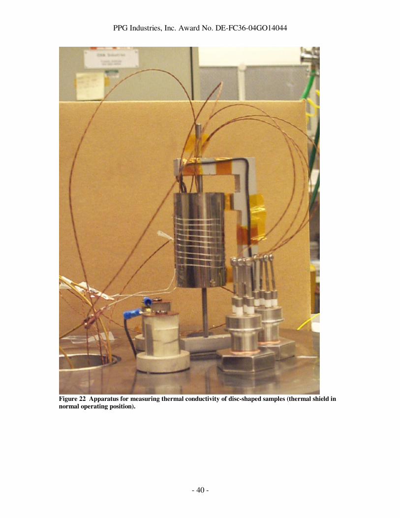
Electrical conductivity (σ) and Seebeck coefficient (S) were also measured for TE film 3C-S versus temperature. Data are given Figure 18 and Figure 19. If values for all three parameters are combined, ZT is estimated to be 1.5 at 275 ºC to 300 ºC, and > 1.5 above 300 ºC. These results were encouraging at the time work was proceeding to grow thick film elements that can be incorporated in a TEG. As a result, the next refinement in the measurement of thermal conductivity was to design a test rig to measure κ that utilized a disk-shaped sample. This test assembly shown schematically in Figure 20 is further illustrated in Figure 21 (showing the symmetrical sample/heater/sample subassembly with heat shield lowered) and Figure 22 (with heat shield in the normal operating position).
Figure 16 Measured thermal loss for a 2 mil Kapton sample and for 16 micron GAST film on Kapton.
Figure 17 Estimated values of thermal conductivity for Sample 3C-S.
0
0.01
0.02
0.03
0.04
0.05
0.06
0.07
0.08
100 150 200 250 300
Thermal Conductivity
Temperature ( ºC )

PPG Industries, Inc. Award No. DE-FC36-04GO14044
- 37 -
0
100
200
300
400
500
600
700
0 100 200 300 400
Electrical Conductivity
Temperature ( ºC) Figure 18 Electrical conductivity versus temperature for Sample 3C-S.
0
50
100
150
200
250
0 100 200 300 400
Temperature ( ºC)
Seebeck Coeff (µV / ºC)
Figure 19 Seebeck coefficient versus temperature for Sample 3C-S.

PPG Industries, Inc. Award No. DE-FC36-04GO14044
- 38 -
Sample Structure
TE Film Deposited onto Metal
Thermal Paste
Metal
Metal
This equipment was used to measure the κ of three sample sets: 1) quartz discs 1 cm diameter and 1.5 mm thick; 2) GAST material deposited on 1.27 cm diameter aluminum discs to a thickness of 125 µm and 3) Type 214 fused quartz discs 1 cm diameter and 1.75 mm thick. Thermal conductivities of the first two materials were achieved under a vacuum of less than 10-5 torr. These experiments indicated a κ value range from 1.99 x 10⁻² to 2.74 x 10⁻² W/cm.K for the first quartz sample set corresponding to a temperature range 27°C to 77°C. The corresponding ranges measured for the GAST sample set was 1.89 x 10⁻³ to 2.41 x 10⁻³ W/cm.K over the temperature range 60°C to 100°C.. However, while the quartz conductivity increased with temperature as expected, the GAST thermal conductivity showed an inverse temperature relationship. This and unexpected low values of κ together with the problem of asymmetrical temperature differences across the samples made the above results quantitatively less reliable despite showing a measure of consistency. The third sample set comprising Type 214 fused quartz with a published κ value of 1.4 x 10⁻² W/cm.K was used as a means of calibrating the overall measurement system. The encouraging result of κ = 1.35 x 10⁻² W/cm.K at 27°C is in close agreement with the expected value. The temperature distribution across the identical samples was also symmetrical. However, performing the measurement at higher temperatures produced the unacceptable result of κ declining instead of increasing with temperature as expected. This illustrated the issue that the arrangement was exhibiting imperfect thermal conductivity between the various layers.
Figure 20 Schematic arrangement of samples and heater for measuring thermal conductivity of thick
TE films

PPG Industries, Inc. Award No. DE-FC36-04GO14044
- 39 -
Figure 21 Apparatus for measuring thermal conductivity of disc-shaped samples (thermal shield
lowered)
PPG Industries, Inc. Award No. DE-FC36-04GO14044
- 40 -
Figure 22 Apparatus for measuring thermal conductivity of disc-shaped samples (thermal shield in
normal operating position).

PPG Industries, Inc. Award No. DE-FC36-04GO14044
- 41 -
TEG Fabrication TEG fabrication involves: selection of n-type and p-type thermoelectric materials; development of a process to fabricate thermoelements using those materials; modeling to determine number of thermocouples, element diameters, and lengths; and finally development of TEG packaging process. PNNL selected GAST for the p-type element, and Ag-PbTe alloys for the n-type element. Thermoelement fabrication was described above. Two basic TEG packaging geometries were considered: flat plate geometry and cylindrical geometry. In the flat plate geometry, exemplified by the design of Figure 7, heat flows normal to the surface of a flat plate at high temperature, through the thermoelectric couples, and to a second flat plate that is kept at a low temperature and serves as the heat sink. Many current thermoelectric generators (e.g. those made by High-Z or Marlow) use this geometry. These devices tend to be small and inefficient. One reason the devices are small is that the two flat plates are made of ceramic material that can withstand high temperatures and is electrically insulating, but is quite brittle and costly. This brittleness and cost makes it difficult to fabricate large (foot-size) pieces, which would be needed for large-scale waste heat recovery with TEGs. We approached several commercial TEG manufacturers in an attempt to find one who would work with us to fabricate a flat plate TEG using the spooled PNNL thermoelements, but none were interested. One manufacturer (Global Thermoelectric) did express willingness to evaluate the compatibility and performance of PNNL thermoelements with the manufacturer’s existing cylindrical TEG geometry. The cylindrical geometry is shown in cross-section in Figure 24 below. Here, the thermoelements are sandwiched between two concentric cylinders. The inner cylinder serves as the high temperature surface, and the outer cylinder is cooled and serves as the low temperature surface. The thermoelements are arranged to capture the radial heat flow and convert it to electricity. As described later, the heat transfer from the slow-moving gas stream in the PPG exhaust flue is inadequate to power directly a cylindrical TEG such as Global Thermoelectric’s Model 7120. However, direct mechanical contact between the inner cylinder and a hot tube could give adequate heat transfer to power the TEG. Given that we did not have a path to fabricate a high-temperature flat plate TEG, and the potential willingness of a TEG manufacturer to evaluate PNNL’s materials in a cylindrical geometry, we focused on a cylindrical TEG for the in-plant test. PNNL had previously studied the cylindrical TEG in a bench-scale test (as described below), so this earlier work formed the basis for our study of industrial waste heat recovery with thermoelectric technology, as discussed in the next section.

PPG Industries, Inc. Award No. DE-FC36-04GO14044
- 42 -
Industrial Waste Heat Recovery with
Thermoelectric Technology
Bench Test of Prototype TEG PNNL built a test bed (Figure 23) for characterizing thermoelectric generators, and used it to evaluate the performance of a Global Thermoelectric Model 7120 cylindrical TEG. The test bed was built around a 2 million-BTU/hr natural gas burner that provided combustion gas temperatures up to about 1150ºC (2100ºF) to simulate temperatures in the off-gas stream of a glass furnace. Test runs were carried out over a period of several months.
Figure 23 PNNL test bed for evaluating thermoelectric generators under waste heat
flows which simulate conditions in industry.
Global TEG With
Cooling Jacket
Blower
Burner

PPG Industries, Inc. Award No. DE-FC36-04GO14044
- 43 -
As shown in Figure 24, the pressures and temperatures of the gas at the inlet and exit of the Global unit were utilized along with measured heat flow through the TEG to carry out fluid thermodynamic calculations. The heat transfer coefficient 'h' was calculated by comparing the values of enthalpy extracted from the gas stream to the heat flowing through the TEG as determined from a calorimetric measurement using a water jacket around the Global TEG. The gas temperature at the inlet (936ºC, 1717ºF) was higher than anticipated apparently due to the inclusion of a mantle inside the TEG to enhance heat transfer (see the cross section in Figure 24). The mantle design could be modified to achieve other desired temperatures and pressure drops.
Testing the Model 7120 TEG was conducted to address questions affecting its operation in the planned in-plant demonstration. The focus of the investigation was 1) the function of the water jacket and 2) the pressure drop associated with the mantle placed inside the TEG to enhance heat transfer. Test runs with reduced cooling showed that the water jacket was not distributing water evenly over the cold surface of the TEG. This was evidently the cause of an asymmetrical elongation of the TEG observed at the highest heating rates in earlier runs. A subsequent discussion with the manufacturer confirmed that, if liquid cooling is desired, a new water jacket should be incorporated that delivers coolant more uniformly. Test runs with and without the mantle in place allowed comparisons at identical gas temperatures of the pressure drop caused by the mantle. Test results showed that the mantle contributed a 4- to 6-fold increase in pressure drop along the axis of the TEG. While removal of the mantle made the converter more amenable to being powered by the natural draft of the melter exhaust, heat transfer between the gas and the hot surface of the converter was degraded when the mantle was absent. This meant that for a given hot side temperature, the gas must be correspondingly hotter by up to several hundred Celsius degrees to maintain the same heat transfer and thereby achieve the same electric output from the TEG. This finding suggests that the mantle design could be instrumental as an
Figure 24 Cross section of converter with key parameters for determining the energy
balance, and an illustration of the inserted mantle.
Tgas = 1717°F
h K
P1, T1
P2, T2
TEG
Mantle
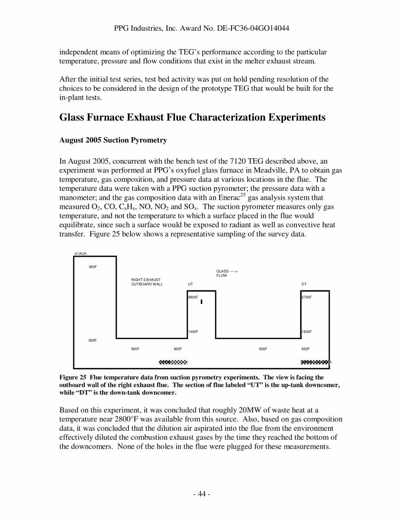
PPG Industries, Inc. Award No. DE-FC36-04GO14044
- 44 -
independent means of optimizing the TEG’s performance according to the particular temperature, pressure and flow conditions that exist in the melter exhaust stream. After the initial test series, test bed activity was put on hold pending resolution of the choices to be considered in the design of the prototype TEG that would be built for the in-plant tests.
Glass Furnace Exhaust Flue Characterization Experiments
August 2005 Suction Pyrometry
In August 2005, concurrent with the bench test of the 7120 TEG described above, an experiment was performed at PPG’s oxyfuel glass furnace in Meadville, PA to obtain gas temperature, gas composition, and pressure data at various locations in the flue. The temperature data were taken with a PPG suction pyrometer; the pressure data with a manometer; and the gas composition data with an Enerac25 gas analysis system that measured O2, CO, CxHx, NO, NO2 and SOx. The suction pyrometer measures only gas temperature, and not the temperature to which a surface placed in the flue would equilibrate, since such a surface would be exposed to radiant as well as convective heat transfer. Figure 25 below shows a representative sampling of the survey data.
STACK
360F
GLASS ----->FLOW
RIGHT EXHAUST
OUTBOARD WALL UT DT
2800F 2700F
1400F 1600F
600F
800F 800F 900F 850F
OPEN OPEN-->CLOSED
Figure 25 Flue temperature data from suction pyrometry experiments. The view is facing the
outboard wall of the right exhaust flue. The section of flue labeled “UT” is the up-tank downcomer,
while “DT” is the down-tank downcomer.
Based on this experiment, it was concluded that roughly 20MW of waste heat at a temperature near 2800°F was available from this source. Also, based on gas composition data, it was concluded that the dilution air aspirated into the flue from the environment effectively diluted the combustion exhaust gases by the time they reached the bottom of the downcomers. None of the holes in the flue were plugged for these measurements.

PPG Industries, Inc. Award No. DE-FC36-04GO14044
- 45 -
The pressure drop from the top to the bottom of the downcomer was measured to be about 0.2” WC, much lower than what was needed to drive the 7120 TEG in the bench test (there, pressure drops across the TEG were around 8” WC). Later in the project, gas velocities were measured directly with pitot tubes, and found to be less than 5 ft/sec. This led the project partners to explore alternative schemes for waste heat recovery in the glass furnace. These schemes would need to be consistent with the observation that convective heat transfer within the exhaust flue would be low, and heat transfer would need to be achieved using either large area devices or by taking advantage of other heat transfer mechanisms (e.g. radiation). Much later in the project, another flue characterization experiment was performed to determine what area of the flue could be blocked by waste heat recovery devices without impacting the glass melting process. This experiment confirmed the low flow rates and pressure drops existing in the exhaust flue, and showed that roughly half of the area of the exhaust flue could be blocked without impacting the glass melting process. This experiment is described in detail below. Flue Damper Experiment
A test was conducted at Meadville to quantify how much additional pressure drop could be sustained by the oxyfuel melter without disturbing the glass manufacturing process. The test results were used to determine how many heat recovery devices could potentially be installed with the existing flue design. This test (and any waste heat recovery scheme) had to consider both flues because of the furnace design. If it did not, the exhaust flow would become unbalanced. To simulate the flow resistance of a bank of waste heat recovery devices plant personnel recommended the use of flow dampers. The slots and lowering equipment for these dampers already existed but the existing dampers were made of 5/8” thick steel sheet. Plant personnel were concerned that the steel plates could warp and stick in place which had the potential of shutting down the tank. To avoid this risk Meadville personnel designed and built new dampers which consisted of a water cooled framework with sheets of high temperature fiberboard to obstruct the exhaust flow. If this became stuck the fiberboard could be easily knocked down restoring normal flow. The test itself was carried out on May 24, 2007 with Adam Polcyn and Bill Siskos (Research), Gary Nelis and Bill Tjader (Engineering), and Dave Girvan, Mark De Young and others from Meadville participating. Several meetings and conference calls were held in preparation for this pressure drop test as well as preparatory work being done to set-up for the test. The preparatory work included installing and wiring instrumentation for the test. The instrumentation (equipment and location supplied by Research) included installation of static pressure taps before and after flue dampers on both the left and right exhaust flues and a, Research modified, S-type pitot tube (Dwyer26 Series 160S “S” type pitot tube) located in the center but protruding six inches below the bottom edge of each damper and oriented to measure velocity pressure due to flow in a direction parallel to the flue centerline. Each pitot tube had a type K thermocouple attached at its end. The four static pressure taps and each pitot tube were connected by hoses to pressure transducers

PPG Industries, Inc. Award No. DE-FC36-04GO14044
- 46 -
(Setra27 Model 260 Series Differential Pressure Transducer) each of which output a DC signal which connected to a computer data acquisition system. The two thermocouples were attached directly to the computer data acquisition system. Per Research recommendations this equipment was installed by plant personnel. We needed to be sure that the test was in no way disruptive of actual line operation, since the line was still in production. It was determined that we would take pressure, flow and temperature readings in both flues during the test. The test involved the lowering the exhaust flue dampers (in both flues) incrementally and monitoring and recording temperature and pressure at each step. It was agreed that as soon as there was any indication that the process was being disrupted we would terminate the test. This would indicate the limit of blockage the process could tolerate before a process disruption occurred. The test was first tried on May 22, 2007 but the dampers jammed. Meadville hot works personnel worked on freeing the flue dampers and clearing any interference on May 23, 2007. The test was successfully completed on May 24, 2007. The results are as follows: It was found that the dampers could be lowered up to four feet from the top of the flue on each side without impacting the operation of the furnace. With the dampers lowered four feet from the top of the flue, the pressure drop across the dampers was about 0.5” water column. Also, using the pitot tube and thermocouple data, the velocities were computed to be roughly 20 ft/sec on the right flue and 35 ft per sec on the left flue (see Figure 26) with the dampers lowered four feet.

PPG Industries, Inc. Award No. DE-FC36-04GO14044
- 47 -
Flue Velocity vs. time
0
5
10
15
20
25
30
35
40
45
0 200 400 600 800
Time (sec)
ve
locity (
ft/s
ec)
R. vel. pitot
L. vel. pitot
Rt. vel. mov avg.
Lt. vel. mov. avg.
Figure 26 Flue velocity with the damper in place, blocking roughly half of the flue cross-section.
Using the velocity data it was possible to compute the total flow with time (see Figure 27).

PPG Industries, Inc. Award No. DE-FC36-04GO14044
- 48 -
tot. flow ft**3/sec
1300
1350
1400
1450
1500
1550
1600
0 100 200 300 400 500 600
time (sec)
tota
l flo
w (
ft**
3/s
ec)
Based on moving average of velocity,
uncorrected to standard conditions. Taken
with damper lowered to four foot position.
Figure 27 Gas flow in the exhaust flue with damper in place.
The flow measurements taken at the plant indicate a total exhaust gas flow of roughly 1450 ft3/sec (see figure 2) at a temperature of about 710°F. At 710°F the gases due to combustion amount to about 200 ft3/sec thus about 1250 ft3/sec of air had to be sucked in from the surroundings through holes in the flue. The ambient was about 110 °F during the experiment thus the heat up is estimated at 600 °F. For this to occur 6266 Btu/sec of heat had to be added to the ambient air from the exhaust gases. As a reality check it would be desirable to compute what the temperature of the combustion gases were before they were mixed with ambient air. This was done using an approximate single value estimate of the specific heats of the constituents rather than integrating up the curve. The temperature change that is needed is computed to be 2686 °F. The gas temperature leaving the furnace would thus be computed to be 3400 °F. This is a few hundred degrees higher that actually measured but not bad considering the approximations. From the North American Combustion Handbook flame temperatures near 3400 °F is what one would expect in the combustion of natural gas or methane. This computation does not include gases given off by the batch during the melting/dissolving process in the tank. The measurement in this experiment of a maximum flow velocity of 35 ft/sec with 0.5” WC pressure drop confirmed the earlier conclusion that the 7120 TEG could not be operated directly by the unmodified exhaust gas stream.
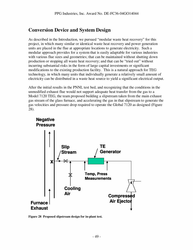
PPG Industries, Inc. Award No. DE-FC36-04GO14044
- 49 -
Conversion Device and System Design As described in the Introduction, we pursued “modular waste heat recovery” for this project, in which many similar or identical waste heat recovery and power generation units are placed in the flue at appropriate locations to generate electricity. Such a modular approach provides for a system that is easily adaptable for various industries with various flue sizes and geometries; that can be maintained without shutting down production or stopping all waste heat recovery; and that can be “tried out” without incurring substantial risks in the form of large capital investments or significant modifications to the existing production facility. This is a natural approach for TEG technology, in which many units that individually generate a relatively small amount of electricity can be distributed in a waste heat source to yield a significant electrical output. After the initial results in the PNNL test bed, and recognizing that the conditions in the unmodified exhaust flue would not support adequate heat transfer from the gas to a Model 7120 TEG, the team proposed building a slipstream taken from the main exhaust gas stream of the glass furnace, and accelerating the gas in that slipstream to generate the gas velocities and pressure drop required to operate the Global 7120 as designed (Figure 28).
CompressedAir EjectorFurnace
Exhaust
Negative Pressure
Slip Stream
Temp, PressMeasurements
Cooling Air
TE Generator
x
CompressedAir EjectorFurnace
Exhaust
Negative Pressure
Slip Stream
Temp, PressMeasurements
Cooling Air
TE Generator
x
Figure 28 Proposed slipstream design for in-plant test.

PPG Industries, Inc. Award No. DE-FC36-04GO14044
- 50 -
However, a number of objections arose to this module design. First, it was not clear how much the energy required to accelerate the gas stream through the generator would offset the energy produced by the TEG itself, making this a potentially unrealistic (or at least inefficient) method to integrate TE technology with the gas stream. Second, this design could obviate the low operation and maintenance costs expected for TE technology. Third, the slipstream would not be a good approximation of conditions inside the flue itself, making it difficult to use slipstream results to predict behavior in the actual exhaust flue. Finally, PNNL considered TEG operation with a slipstream that did not include a compressed air ejector, i.e. a TEG driven by the natural gas flow available in the flue. It was found that the heat transfer coefficient in such a case was an order of magnitude lower than with the ejector, requiring temperature differences between the gas and the TEG of considerably greater than 2000°F. The materials required to build a slipstream that would withstand such temperatures was enough to reject this design as impractical. After abandoning the slipstream approach, the team decided to look for module designs that would harvest waste heat from the exhaust gas stream without substantially modifying the existing properties of the gas stream. The primary challenges here are to obtain excellent heat transfer from the exhaust stream to the TEG hot face and to be compatible with the flue environment (i.e. address presence of condensates, as well as high temperatures). PNNL performed some preliminary conceptual design work to evaluate a flat plate converter exposed to the flue gas as illustrated in Figure 29. A pancake-shaped converter (using Global Thermoelectric’s 5120 unit as an example) is mounted on an insert that fits existing windows in the flue. A flow diverter is supported above the hot shoe to direct flue gasses onto the TEG. The diverter is in the form of a scoop that causes partial stagnation of the hot gas in the space it encloses. At 1450°F, a one foot square scoop opening above each TEG will intercept about 1.3 MMBTU/hr (384 kWt). The 5120 TEG produces 120 We at 7 V and 5% efficiency. Thus, it must receive about 2400 Wt of heat to operate at its design point. This can be achieved by designing the rear of the scoop to leak the appropriate amount of gas consistent with 2400 Wt out of the potential 384 kWt being transferred into the hot shoe. The tail end of the scoop acts as a “waste gate” that “leaks” gas back into the main stream at a rate that is controlled by the longitudinal pressure drop in the flue and eddy entrainment motion that occurs at its mouth. Also included in the design of this module is the concept of applying fins to the cold face of the TEG, and opening holes in the flue wall downstream of the module. In this way, it was hypothesized that room air would be aspirated into the flue, passing over the fins and providing cooling to the cold face of the TEG. This “natural draft cooling” concept was used for the economic analysis described below.

PPG Industries, Inc. Award No. DE-FC36-04GO14044
- 51 -
Figure 29 Exploded Schematic of Flat Plate TEG, Diverter and Window Port Adapter.
In addition to this “diverter” module described above, a “boom” module geometry was considered. In the boom geometry, a flat-plate TEG is hung from a boom extended directly into the gas stream, and exhaust gas heat is transferred to the TEG via direct gas impingement. This design has the advantages of allowing the operator to adjust the convective heat transfer by adjusting the angle of the flat-plate TEG relative to the gas flow direction, and the possibility that the gas flowing over the surface could minimize build up of particulate on the surface. Also, such a geometry could take advantage of radiant heat transfer from the furnace. On the other hand, since the entire TEG is submerged in the hot gas stream, cooling of the cold face of the TEG (the face opposite the face on which hot gas impinges) would be relatively inefficient.
Exhaust GasExhaust GasTEGExhaust GasExhaust GasTEG
Figure 30 Boom module geometry, looking across the flue cross-section.

PPG Industries, Inc. Award No. DE-FC36-04GO14044
- 52 -
TEGTEG
In addition to these diverter and boom modules, the heat pipe module was proposed (Figure 32). The concept is to insert a heat pipe into the exhaust flue, and attach a cylindrical TEG (such as the Global Thermoelectric Model 7120) to the condenser end of the heat pipe, which is outside of the flue. A heat pipe is a sealed, evacuated tube containing a small amount of working fluid (for the temperatures of interest here, possible fluids include sodium and potassium) and a wick. The working fluid is evaporated by the waste heat applied to one end of the heat pipe (the end inserted in the exhaust gas flue), and condenses back to a liquid at the point where the heat pipe contacts the inner cylinder of the TEG. As the liquid condenses, it gives up its latent heat, which is used by the TEG to generate electricity. After condensing, the working fluid rapidly flows back down the heat pipe under gravity and the capillary forces produced by the wick, where it evaporates again, thereby restarting the heat transfer cycle. Heat pipes are known as “superconductors” of heat, as very little heat is lost in the vaporization/condensation cycle of the sodium liquid. Heat pipe technology has been under development for over 45 years, and currently has a number of commercial applications, including the efficient removal of heat from computer chips (with water as the working fluid). Heat pipes are attractive for use as heat exchangers in this application because of their excellent heat transfer efficiency, and excellent durability and reliability28,29. This design makes it possible to separate the problems of heat recovery and electricity generation; takes the TEG itself out of the flue environment, thereby greatly simplifying the requirements on its design and construction, making operation and maintenance of the TEG much more convenient, and allowing for both air and water cooling options; and efficiently transfers the captured heat to the TEG. Finally, the heat pipe module has a “heat concentrating” functionality; i.e., it collects heat from the flue along the entire surface area of heat pipe that is inside the flue, and (ideally) deposits heat only over the area where it contacts the TEG. For our geometry, this implies that the heat flux available inside the flue can be an order of magnitude lower than what is required to operate the TEG. For these reasons, the heat pipe module geometry was eventually chosen for the in-plant test as the most promising and most practical approach.
Figure 31 Boom module geometry, looking down the length of the flue.

PPG Industries, Inc. Award No. DE-FC36-04GO14044
- 53 -
An additional geometry for heat collection proposed during this project was the “pin-fin” geometry. Pin-fin arrays are arrays of cylindrical posts placed such that turbulent flow is achieved inside the array for improved heat transfer, while maintaining fairly low pressure drops across the array and allowing air to enter the array from any direction. These arrays are used to cool chips in the computer industry. Arrays with posts consisting of biaxial cylinders, with cooling water flowing in the central cylinder, and TE modules placed between the inner and outer cylinder, were proposed. This arrangement provides for easy removal of individual posts for cleaning or other maintenance, as well as efficient use of cooling water. A downside to this concept is that thermal expansion
differences between the hot outer and cool inner cylinders could cause poor thermal contact to the TE modules upon inserting the device into the flue. Working from the pin-fin concept, pin-fin arrays of heat pipes were also proposed, with TE modules attached to the pipes external to the flue. This arrangement also provides for easy removal of individual pipes, and the added advantage of having the modules external to the flue where they can be easily accessed and cooled via air, water, or a combination of both.
Figure 32 Heat pipe module geometry, looking down the length of the flue.
CCyylliinnddrriiccaall ““SSlleeeevvee”” TTEEGG((ss))
HHeeaatt ppiippee
HHeeaatt ttrraannssffeerr ffiinnss
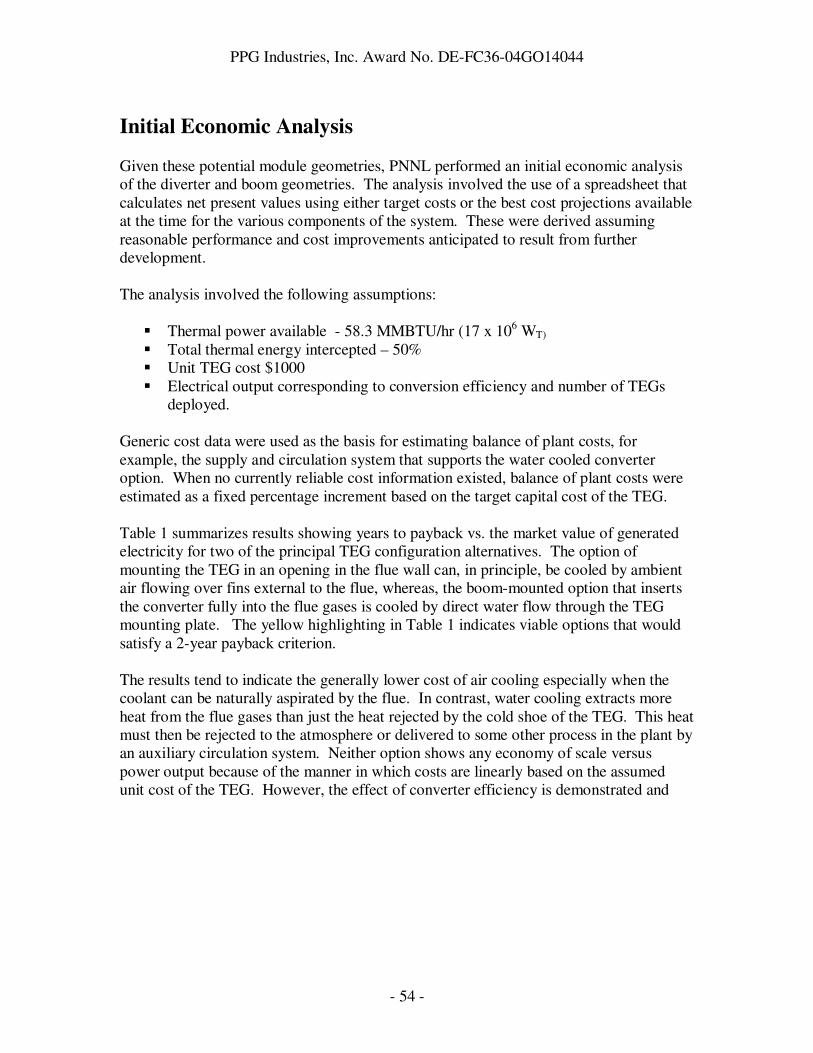
PPG Industries, Inc. Award No. DE-FC36-04GO14044
- 54 -
Initial Economic Analysis Given these potential module geometries, PNNL performed an initial economic analysis of the diverter and boom geometries. The analysis involved the use of a spreadsheet that calculates net present values using either target costs or the best cost projections available at the time for the various components of the system. These were derived assuming reasonable performance and cost improvements anticipated to result from further development. The analysis involved the following assumptions:
� Thermal power available - 58.3 MMBTU/hr (17 x 106 WT) � Total thermal energy intercepted – 50% � Unit TEG cost $1000 � Electrical output corresponding to conversion efficiency and number of TEGs
deployed. Generic cost data were used as the basis for estimating balance of plant costs, for example, the supply and circulation system that supports the water cooled converter option. When no currently reliable cost information existed, balance of plant costs were estimated as a fixed percentage increment based on the target capital cost of the TEG. Table 1 summarizes results showing years to payback vs. the market value of generated electricity for two of the principal TEG configuration alternatives. The option of mounting the TEG in an opening in the flue wall can, in principle, be cooled by ambient air flowing over fins external to the flue, whereas, the boom-mounted option that inserts the converter fully into the flue gases is cooled by direct water flow through the TEG mounting plate. The yellow highlighting in Table 1 indicates viable options that would satisfy a 2-year payback criterion. The results tend to indicate the generally lower cost of air cooling especially when the coolant can be naturally aspirated by the flue. In contrast, water cooling extracts more heat from the flue gases than just the heat rejected by the cold shoe of the TEG. This heat must then be rejected to the atmosphere or delivered to some other process in the plant by an auxiliary circulation system. Neither option shows any economy of scale versus power output because of the manner in which costs are linearly based on the assumed unit cost of the TEG. However, the effect of converter efficiency is demonstrated and
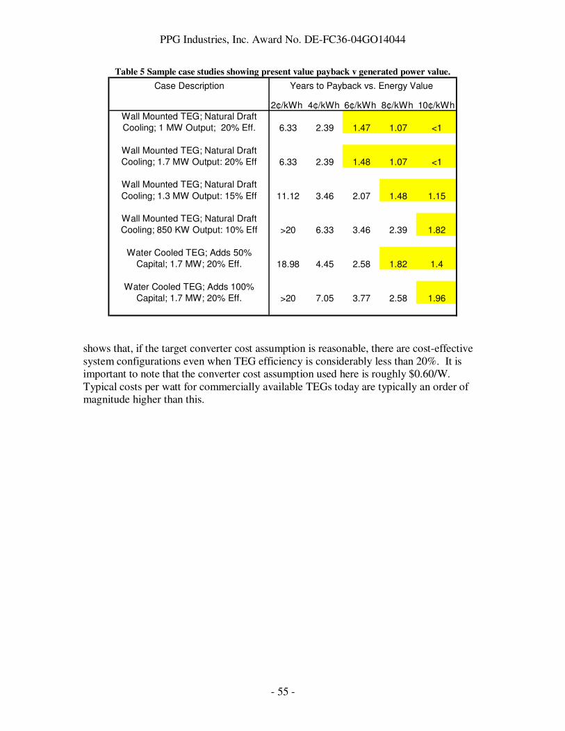
PPG Industries, Inc. Award No. DE-FC36-04GO14044
- 55 -
Table 5 Sample case studies showing present value payback v generated power value.
Case Description Years to Payback vs. Energy Value
2¢/kWh 4¢/kWh 6¢/kWh 8¢/kWh 10¢/kWh
Wall Mounted TEG; Natural Draft
Cooling; 1 MW Output; 20% Eff. 6.33 2.39 1.47 1.07 <1
Wall Mounted TEG; Natural Draft
Cooling; 1.7 MW Output: 20% Eff 6.33 2.39 1.48 1.07 <1
Wall Mounted TEG; Natural Draft
Cooling; 1.3 MW Output: 15% Eff 11.12 3.46 2.07 1.48 1.15
Wall Mounted TEG; Natural Draft
Cooling; 850 KW Output: 10% Eff >20 6.33 3.46 2.39 1.82
Water Cooled TEG; Adds 50%
Capital; 1.7 MW; 20% Eff. 18.98 4.45 2.58 1.82 1.4
Water Cooled TEG; Adds 100%
Capital; 1.7 MW; 20% Eff. >20 7.05 3.77 2.58 1.96
shows that, if the target converter cost assumption is reasonable, there are cost-effective system configurations even when TEG efficiency is considerably less than 20%. It is important to note that the converter cost assumption used here is roughly $0.60/W. Typical costs per watt for commercially available TEGs today are typically an order of magnitude higher than this.

PPG Industries, Inc. Award No. DE-FC36-04GO14044
- 56 -
PPG In-Plant Test of Waste Heat Recovery with TE
Technology
Because waste heat recovery from an oxy-fuel exhaust gas stream had never been attempted (to our knowledge) with TE technology, the project team felt that it was worthwhile to test conventional (3-5% efficiency) TE technology at PPG while PNNL was developing the materials for the advanced TEG. With this approach, it was hoped that many of the expected challenges related to integrating TE technology into a glass furnace environment would be identified and resolved before receiving the advanced TEG, thereby accelerating project progress. In addition, some of the findings from such a test were expected to be valuable inputs for the design of the advanced TEG. Recall from the Background section that combustion exhaust gases exit the oxy-fuel furnace through four ports. These gases then are pulled via natural draft down vertical sections of the flue known as “downcomers”. From here, they flow into two horizontal “connecting flue” sections (one on either side of the furnace) before being ejected out the stacks. The flue is at a slight negative pressure relative to the ambient, so a small number of bricks are removed from the flue walls to allow ambient air to flow into the downcomers and connecting flues to cool the combustion exhaust gases before ejection. When the gases leave the furnace and enter the downcomers, the gas temperature is around 2700°F, with composition roughly 50% water, 35% carbon dioxide, and the remainder nitrogen and a small quantity of oxygen. At the bottom of the downcomers, entering the connecting flue, the gas temperature is around 800°F, with composition roughly 75% nitrogen, 20% oxygen, and the remainder equally split between carbon dioxide and water. Thus by the time the gas reaches the bottom of the downcomers, it has composition very close to that of normal ambient air, indicating that the combustion gas has been highly diluted by the aspirated ambient air. The gas velocity is quite low; in the connecting flue area just beyond the downcomer, gas velocities below 5 ft/sec are typical. The bottoms of the four downcomers are the hottest points in the exhaust flue that are easily accessible from the basement floor of the furnace building. In addition to being the closest points to the furnace that are also easily accessible, they are in line-of-sight of the very hot upper downcomer region, which is heated by radiation emitted by the furnace. For these reasons, it was proposed to perform the in-plant test at the bottom of the right downtank downcomer. Before proceeding with the expense of the in-plant test, further characterization experiments on the proposed in-plant test site were performed. The purpose of these was to confirm that the temperatures required to power the TEG could be obtained at the site, and to better understand heat transfer mechanisms at the test site in order to design the most effective heat recovery module. Spoon Run 0: Flue Temperature Characterization “Spoon” is a generic term used by PPG to describe a probe, generally cooled by air or water, that can be inserted into a hot environment (such as the exhaust stream) to collect certain data on the hot environment. A spoon known as the “Materials Testing Spoon”

PPG Industries, Inc. Award No. DE-FC36-04GO14044
- 57 -
was custom-fabricated for this project. It was designed to measure directly both spoon surface temperature and heat flux through the spoon as condensates built up over time on the spoon surface. It also proved useful for simple characterization of temperature inside the flue. In Run 0 of the Materials Testing Spoon, a heat flux transducer (HFT) obtained from Thermonetics30 was cemented to the top surface of the spoon and placed in the exhaust stream at 1400°F gas temperature, 1150°F spoon top surface temperature, for three days. The HFT wires corroded and broke in the flue environment over this time, and the thermal connection between the HFT and the spoon weakened to the point that the HFT was easily removed from the spoon top surface. However, important information for the in-plant test was obtained in Run 0, which is therefore described in some detail below. Run 0: A high-temperature heat flux transducer for use up to 1650°F was obtained from Thermonetics Corp. This HFT is ¾”x ¾” thermopile covered with a glass frit glazing. Chromel wire was spot-welded to the ends of the HFT wires to make them long enough to extend into the exhaust flue. Then the Thermonetics HFT was cemented to the top surface of the spoon using Sauereisen31 Aluseal Adhesive Cement #2. After drying overnight, the cement was further dried at elevated temperature. The HFT calibration constant varied with temperature, 280 BTU/hr/ft2/mV at 1200°F and 345 BTU/hr/ft2/mV at 1600°F.

PPG Industries, Inc. Award No. DE-FC36-04GO14044
- 58 -
Combined valve/meter to throttle and measure air flow
Air inlet/outlet pipes shown offset for clarity; in actual, inlet pipe should be directly over outlet pipe
TOP VIEW MATERIALS TESTING
SPOON
Heat Flux Transducer cemented to top surface of spoon
Brick pattern shows placement of insulation during ITI HFT Run
Figure 33 Top view of Materials Testing Spoon in configuration used for Run 1. In Run 0, insulation
was also applied around the inlet and outlet pipes.

PPG Industries, Inc. Award No. DE-FC36-04GO14044
- 59 -
Air Out
Air In
Tint
Internal spoon temperature (Tint) measured here
TGS
Gas stream temperature measured here
Dashed arrows show path of air
through spoon
SIDE VIEW
The configuration of the spoon as used in this experiment is shown in Figure 33 and Figure 34. Kaowool32 was used to insulate all surfaces of the spoon except for the top surface, so that the heat flux measured by the spoon would be primarily through the top surface and would be absorbed by the cooling air impinging on the top surface. Insulation was also applied over the inlet and outlet air pipes in this experiment only in an attempt to measure the temperature change of the cooling air as it picked up heat from the spoon. The objectives for this run were:
1. To assess whether the temperatures required for the in-plant demonstration (800°C gas temperature, 650°C heat pipe surface) could be achieved at the bottom of the downcomer.
2. Assuming the first objective could be met, measure the heat flux through the heat flux transducer under the surface and gas temperatures relevant for the in-plant demonstration. Compare the result to the heat flux required to power the 7120 TEG.
Figure 34 Side view of Materials Testing Spoon in configuration used for Runs 0,1. Insulation is not
shown in this drawing for clarity.
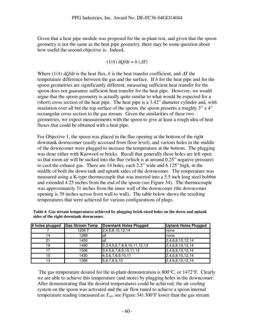
PPG Industries, Inc. Award No. DE-FC36-04GO14044
- 60 -
Given that a heat pipe module was proposed for the in-plant test, and given that the spoon geometry is not the same as the heat pipe geometry, there may be some question about how useful the second objective is. Indeed,
(1/A) dQ/dt = h (∆T) Where (1/A) dQ/dt is the heat flux, h is the heat transfer coefficient, and ∆T the temperature difference between the gas and the surface. If h for the heat pipe and for the spoon geometries are significantly different, measuring sufficient heat transfer for the spoon does not guarantee sufficient heat transfer for the heat pipe. However, we would argue that the spoon geometry is actually quite similar to what would be expected for a (short) cross section of the heat pipe. The heat pipe is a 3.42” diameter cylinder and, with insulation over all but the top surface of the spoon, the spoon presents a roughly 3” x 4” rectangular cross section to the gas stream. Given the similarities of these two geometries, we expect measurements with the spoon to give at least a rough idea of heat fluxes that could be obtained with a heat pipe. For Objective 1, the spoon was placed in the flue opening at the bottom of the right downtank downcomer (easily accessed from floor level), and various holes in the middle of the downcomer were plugged to increase the temperature at the bottom. The plugging was done either with Kaowool or bricks. Recall that generally these holes are left open so that room air will be sucked into the flue (which is at around 0.25” negative pressure) to cool the exhaust gas. There are 14 holes, each 2.5” wide and 6.125” high, in the middle of both the down tank and uptank sides of the downcomer. The temperature was measured using a K-type thermocouple that was inserted into a 5.5 inch long steel bobbin and extended 4.25 inches from the end of the spoon (see Figure 34). The thermocouple was approximately 31 inches from the inner wall of the downcomer (the downcomer opening is 39 inches across from wall to wall). The table below shows the resulting temperatures that were achieved for various configurations of plugs.
The gas temperature desired for the in-plant demonstration is 800°C, or 1472°F. Clearly we are able to achieve this temperature (and more) by plugging holes in the downcomer. After demonstrating that the desired temperatures could be achieved, the air cooling system on the spoon was activated and the air flow tuned to achieve a spoon internal temperature reading (measured as Tint, see Figure 34) 300°F lower than the gas stream
Table 6 Gas stream temperatures achieved by plugging brick-sized holes on the down and uptank
sides of the right downtank downcomer.
# holes plugged Gas Stream Temp Downtank Holes Plugged Uptank Holes Plugged
7 1206 F 2,4,6,8,10,12,14 none
14 1289 all none
21 1450 all 2,4,6,8,10,12,14
19 1490 2,3,4,5,6,7,8,9,10,11,12,13 2,4,6,8,10,12,14
17 1506 3,4,5,6,7,8,9,10,11,12 2,4,6,8,10,12,14
15 1430 4,5,6,7,8,9,10,11 2,4,6,8,10,12,14
13 1386 5,6,7,8,9,10 2,4,6,8,10,12,14

PPG Industries, Inc. Award No. DE-FC36-04GO14044
- 61 -
temperature. This is consistent with the temperature difference estimated by the heat pipe manufacturer to drive sufficient heat into the unfinned heat pipe for the 7120 TEG. It was found that 1.5scfm was sufficient to achieve the temperature difference desired. The data taken with air flow at 1.5scfm are shown in Table 7.
In the table above, “Run” signifies the name of the data run. The names correspond with the number of downcomer holes that were plugged for that run. “Day/time” signify the time frame over which data were acquired for that run. For each quantity, average, maximum, and minimum values are reported to give a sense for variation in each quantity during the run. Since there were slight, non-statistical, variations in the flue conditions during the run, we report max and min values rather than a standard deviation. “Internal” is the internal spoon temperature (see Figure 34). “HFT” is the voltage read from the Thermonetics heat flux transducer, which can be multiplied by a temperature-dependent calibration constant to obtain the heat flux in BTU/hr/ft2. “Inlet” and “Outlet” are the temperatures measured on the outside of the inlet and outlet pipes carrying the cooling air to and from the spoon. “Gas stream” is the gas stream temperature measured by the thermocouple enclosed in a steel bobbin and extended past the end of the spoon (see Figure 34). “HFT Heat Flux” is the increase in heat flux measured by the Thermonetics HFT upon turning on the 1.5scfm cooling air to the spoon (and waiting for equilibrium to be re-established). It is computed by subtracting a “background” heat flux measured when no cooling air was flowing to the spoon from the heat flux measured when cooling air was flowing. “Enthalpy to Air” is the calculated enthalpy transferred to the cooling air as it flows from the inlet to the outlet pipe, and includes enthalpy picked up while traveling through the pipes as well as in the spoon itself. The inlet and outlet pipes were covered with Kaowool insulation to minimize the amount of heat transferred to the cooling air while in the pipes, but we did not do experiments to separate out enthalpy transferred through the pipes versus through the spoon. “GS-Int” is the difference between the gas stream and internal temperatures.
Table 7 Summary of heat flux data taken on air-cooled spoon.
Internal HFT Inlet Outlet Gas Stream HFT Heat Flux Enthalpy to Air GS-Int
Run Day/Time Statistic °F mV °F °F °F BTU/hr/ft2 BTU/hr °F
plug 19 1/29 pm - avg 1182 33 69 320 1490 9113 385 308
1/30 am max 1209 37 72 337 1523 10485 407
min 1144 28 67 307 1450 7722 367
plug 15 1/30 late am avg 1116 26 73 259 1430 7209 282 313
max 1165 35 74 301 1441 9672 346
min 1030 20 72 192 1416 5501 175
plug 13 0 1/30 early pm avg 1159 15 74 309 1408 4257 358 249
max 1168 19 75 314 1427 5219 366
min 1153 12 74 302 1392 3222 348
plug 13 1 1/30 pm - avg 1159 9 75 304 1386 2596 349 228
2/2 am max 1197 16 78 313 1429 4363 360
min 1127 3 72 289 1345 970 330

PPG Industries, Inc. Award No. DE-FC36-04GO14044
- 62 -
As the table shows, the temperatures of the gas environment (as measured by TGS) and of the spoon surface (as measured by Tint) were close to those desired for the in-plant test (1472°F environment, 1200°F surface) for all of the runs. The heat flux measured by the Thermonetics HFT started near 9113 BTU/hr/ft2, then dropped consistently for subsequent runs to a minimum of 2596 BTU/hr/ft2 in the last run. In these units, the heat flux that must be collected by the heat pipe to power the 7120 TEG is 1966 BTU/hr/ft2 (0.62 W/cm2). The measured heat fluxes are at least comparable to this, although clearly a dramatic decline in measured heat flux occurred over the course of these experiments. Another measure of heat flux to the spoon is the enthalpy transferred to the cooling air. While this shows some decrease in later runs compared to the first run, the decline is much less dramatic than what was seen by the HFT (10% versus a factor of 3). One explanation for the dramatic decline in HFT heat flux could be rapid collection of particulate. However, even after the extended “plug 13 1” run, there was not enough white powder on the HFT to collect for measurement. There were also some solid “grains” of material on the HFT, although these were sparse on the HFT. After removing the probe from the flue after “plug 13 1”, a large buildup of solid material was noticed over the insulation covering the air pipes, and a red glow was seen just under this buildup, indicating that the area was very hot. Also, the voltage on the HFT rapidly climbed to saturation starting around 2100 hours on 1 February. After removing the buildup and insulation, it was noticed that an HFT electrical lead had broken in that region, most likely due to the excessive heating observed at that point. Also, the cement bond between the HFT and the spoon surface had degraded to the point where the HFT could be easily removed from the spoon surface by hand. Hence, we believe that the decline in heat flux over the course of these experiments was most likely due to degrading thermal contact between the HFT and the spoon surface, and the sharp rise in voltage after 2100 hours was due to the HFT wires breaking.
0.000
0.010
0.020
0.030
0.040
0.050
0.060
0.070
0.080
12:1
5:5
8
16:1
4:5
5
20:1
3:5
3
0:1
2:5
0
4:1
1:4
7
8:1
0:4
5
12:0
9:4
2
16:0
8:4
0
20:0
7:3
7
0:0
6:3
4
4:0
5:3
2
8:0
4:2
9
12:0
3:2
6
16:0
2:2
4
20:0
1:2
1
0:0
0:1
8
3:5
9:1
6
7:5
8:1
3
Time
HF
T V
olt
ag
e (
V)
Figure 35 Heat flux transducer voltage towards the end of run "plug 13 1".
The overall conditions of the downcomer did change due to the plugged holes and resulting increase in temperature in that region. The inside walls of the downcomer are generally covered with an “ice” composed of solid sodium sulfate and other
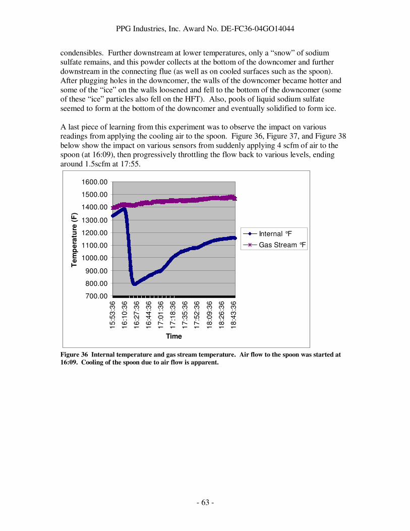
PPG Industries, Inc. Award No. DE-FC36-04GO14044
- 63 -
condensibles. Further downstream at lower temperatures, only a “snow” of sodium sulfate remains, and this powder collects at the bottom of the downcomer and further downstream in the connecting flue (as well as on cooled surfaces such as the spoon). After plugging holes in the downcomer, the walls of the downcomer became hotter and some of the “ice” on the walls loosened and fell to the bottom of the downcomer (some of these “ice” particles also fell on the HFT). Also, pools of liquid sodium sulfate seemed to form at the bottom of the downcomer and eventually solidified to form ice. A last piece of learning from this experiment was to observe the impact on various readings from applying the cooling air to the spoon. Figure 36, Figure 37, and Figure 38 below show the impact on various sensors from suddenly applying 4 scfm of air to the spoon (at 16:09), then progressively throttling the flow back to various levels, ending around 1.5scfm at 17:55.
700.00
800.00
900.00
1000.00
1100.00
1200.00
1300.00
1400.00
1500.00
1600.00
15
:53
:36
16
:10
:36
16
:27
:36
16
:44
:36
17
:01
:36
17
:18
:36
17
:35
:36
17
:52
:36
18
:09
:36
18
:26
:36
18
:43
:36
Time
Te
mp
era
ture
(F
)
Internal °F
Gas Stream °F
Figure 36 Internal temperature and gas stream temperature. Air flow to the spoon was started at
16:09. Cooling of the spoon due to air flow is apparent.

PPG Industries, Inc. Award No. DE-FC36-04GO14044
- 64 -
0.00
100.00
200.00
300.00
400.00
500.00
600.00
15
:53
:36
16
:07
:56
16
:22
:16
16
:36
:36
16
:50
:56
17
:05
:16
17
:19
:36
17
:33
:56
17
:48
:16
18
:02
:36
18
:16
:56
18
:31
:16
18
:45
:36
Time
Te
mp
era
ture
Inlet °F
Outlet °F
Figure 37 Response of inlet and outlet air temperatures to introducton of air flow to the spoon at
16:09.
0.0000
0.0100
0.0200
0.0300
0.0400
0.0500
0.0600
0.0700
0.0800
0.0900
0.1000
15
:53
:36
16
:04
:11
16
:14
:46
16
:25
:21
16
:35
:56
16
:46
:31
16
:57
:06
17
:07
:41
17
:18
:16
17
:28
:51
17
:39
:26
17
:50
:01
18
:00
:36
18
:11
:11
18
:21
:46
18
:32
:21
18
:42
:56
Time
HF
T V
olt
ag
e (
V)
Figure 38 Response of Thermonetics HFT to introduction of air flow to the spoon at 16:09. The
HFT was saturated from 16:09 through 17:28.

PPG Industries, Inc. Award No. DE-FC36-04GO14044
- 65 -
The Materials Testing Spoon was used again later in the project to characterize the impact of particulate buildup on heat transfer to the air-cooled surface. This experiment is described later in this report. Gardon Gage Radiometry
In order to increase our understanding of the convective and radiative heat sources and sinks at the site for the in-plant test, we measured radiant heat flux using a water cooled Gardon gage radiometer (Vatell Corp. Thermogage Circular Foil Heat Flux Gage Model No. 1000-34). The radiometer is constructed such that it generates a signal from a sensor that is proportional to radiant heat flux received. It measures this heat flux over a cone with a 62° total included angle. The emissivity on the sensor surface is 0.94 and is shielded from convection by a thin sapphire window. The temperature of the sensor is effectively the water temperature. Assuming gray body behavior, the effective temperature of the source of the radiation can be estimated via the Stefan-Boltzman equation. As a result of the procedure for calibrating the radiometer, the view factor would be 1.0. Using a relatively high emissivity, typical of ceramic or corroded surfaces, of 0.7 and a view factor of 1.0 the effective temperature of the surroundings in the direction noted was calculated, see Table 8. This data was taken at the in-plant test location, viz. the bottom of the right, down tank, downcomer. In addition to the effective temperature the effect of position in the flue was explored. This was limited by the length of the heat flux probe. Additionally, the Gardon gage was checked by measuring a heated metal plate both before and after the in plant measurements to assure the sensor was operating properly. It must be noted that the data in Table 8, and for that matter all the data in this report, has been collected at certain operating conditions. These are subject to change without compromising the operation of the process. The effective radiant source temperatures given in Table 8 have to be looked at in concert with spoon and suction pyrometer measurements. Table 8 Gardon gage radiometer data.
Radiometer facing up dist. Protruding (in.) effective temp (F) 24 1300 24 1313 24 1318 36 1352 36 1373 Radiometer facing down 24 1094 24 1107

PPG Industries, Inc. Award No. DE-FC36-04GO14044
- 66 -
36 1169 36 1159 Radiometer facing outer wall dist. Protruding (in.) effective temp (F) 24 1075 24 1079 36 1106 36 1088 Radiometer facing inner wall 24 1117 24 1105 36 1134 36 1181 As we have mentioned elsewhere, a significant amount of air leaks into the flues on both sides of the furnace both intentionally and by accident thus dropping the exhaust gas temperature from probably in excess of 3000 °F (in the furnace) to nominally 700 °F in the connecting flue between the two downcomers. Based on the spoon and Gardon gage experiments, we hypothesized that a surface placed at the in-plant test site was heated primarily by radiant heat from the furnace at the top of the downcomer, and the surface was convectively cooled by the relatively cold room air that made up the majority of the exhaust stream at the bottom of the downcomer. A combined suction pyrometer / spoon experiment was performed to confirm this hypothesis, as described below. August 2007 Suction Pyrometry/Spoon Experiment
Because of the radiation sources within view it was determined a simple thermocouple suspended in the flow may not give an accurate gas temperature. A thermocouple, simply suspended in a gas, will come into thermal equilibrium with its surroundings. This usually involves radiation and convection. For example, with relatively low flow of cool gas and intense radiation sources within view, an exposed thermocouple can read much higher than the gas temperature. To obtain the gas temperature a thermocouple must be shielded from radiation in a small tube with insulation on the tube’s exterior, and the gas drawn at high velocity through the tube and over the thermocouple. To do this, the tube is placed in the gas, the temperature of which is to be determined, and placed under a partial vacuum with an air ejector attached to the other end of the tube outside of the hot environment. The thermocouple is read as a function of gas velocity across the thermocouple junction. When increasing gas velocity (i.e. vacuum) produces no discernable change in temperature, the correct gas temperature has been found. This procedure simply increases the convective heat transfer to a point where it overwhelms the radiation and/or conductive heat transfer.
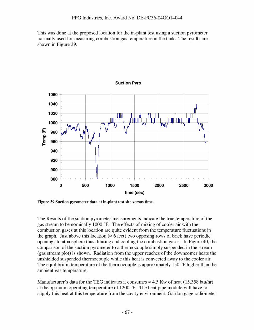
PPG Industries, Inc. Award No. DE-FC36-04GO14044
- 67 -
This was done at the proposed location for the in-plant test using a suction pyrometer normally used for measuring combustion gas temperature in the tank. The results are shown in Figure 39.
Suction Pyro
880
900
920
940
960
980
1000
1020
1040
1060
0 500 1000 1500 2000 2500 3000
time (sec)
Tem
p (
F)
Figure 39 Suction pyrometer data at in-plant test site versus time.
The Results of the suction pyrometer measurements indicate the true temperature of the gas stream to be nominally 1000 °F. The effects of mixing of cooler air with the combustion gases at this location are quite evident from the temperature fluctuations in the graph. Just above this location (≈ 6 feet) two opposing rows of brick have periodic openings to atmosphere thus diluting and cooling the combustion gases. In Figure 40, the comparison of the suction pyrometer to a thermocouple simply suspended in the stream (gas stream plot) is shown. Radiation from the upper reaches of the downcomer heats the unshielded suspended thermocouple while this heat is convected away to the cooler air. The equilibrium temperature of the thermocouple is approximately 150 °F higher than the ambient gas temperature. Manufacturer’s data for the TEG indicates it consumes ≈ 4.5 Kw of heat (15,358 btu/hr) at the optimum operating temperature of 1200 °F. The heat pipe module will have to supply this heat at this temperature from the cavity environment. Gardon gage radiometer

PPG Industries, Inc. Award No. DE-FC36-04GO14044
- 68 -
measurements (Table 8) indicate the walls and floor of the downcomer are colder than 1200 °F and thus would tend to prevent the heat pipe from reaching 1200 °F under present operating conditions. If the heat pipe were perfectly insulated from these radiation sinks (floor and walls), the view factor to the upper source were close to 1.0, the combined emissivity were 1.0, and the convective losses were eliminated, there would be enough heat due to radiation to supply the TEG through the heat pipe. Spoon heat flux data on Figure 41 shows that at about 3500 sec into the experiment, the spoon temperature was in excess of 1100 °F but the heat flux to the spoon was less than 1500 btu/(hr ft2). However, this is without any thermal load applied to the spoon. When cooling air is applied to the spoon (simulating the thermal load of the TEG), it appears that the required heat flux of 3430 btu/hr/ft2 can be drawn from the flue while incurring a temperature drop of around 300 °F. For the in-plant test, the overall temperature inside the flue will need to be raised by plugging holes in the downcomer. According to thermal modeling for the heat pipe, if the heat pipe surface is held at 1200 °F, the TEG hot surface will be at roughly 1100°F, the required hot surface temperature for optimal operation. Assuming the spoon and heat pipe have similar heat transfer coefficients, the heat pipe will need to be at a temperature of 1500°F without any thermal load on it. As described above, we can reach 1500°F at the in-plant test site by plugging holes in the downcomer. Based on these experiments, fins were added to the heat pipe used for the in-plant test, and were designed so that the maximum surface area faces the top of the downcomer, which is the primary radiation source. By plugging holes in the downcomer, we expected to be able to reduce convective cooling, increase the flue wall temperatures, and increase the effectiveness of the radiation source and therefore the temperature of the heat pipe. We expected that it would be possible to operate the TEG at optimal power output provided the heat pipe surface is clean. We also expected that over the course of two weeks, the output would be reduced dramatically by the collection of particulate on the heat pipe surface. We planned to apply an air lance through an existing hole that would have good visibility to the heat pipe to try to clean the heat pipe surface during the test.
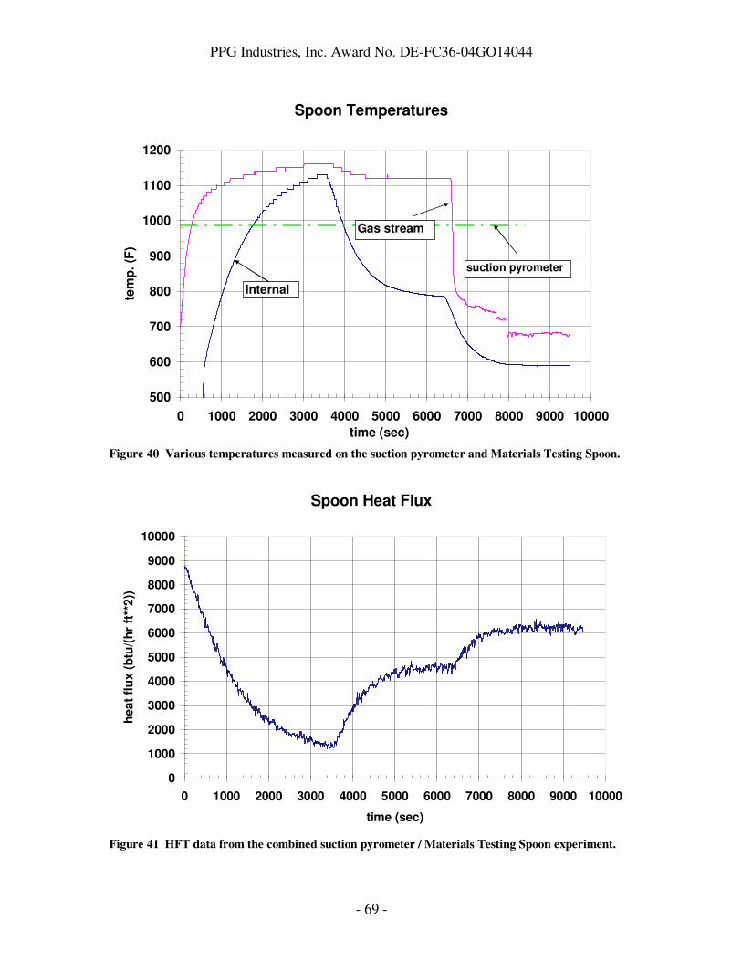
PPG Industries, Inc. Award No. DE-FC36-04GO14044
- 69 -
Spoon Temperatures
500
600
700
800
900
1000
1100
1200
0 1000 2000 3000 4000 5000 6000 7000 8000 9000 10000
time (sec)
tem
p.
(F)
suction pyrometer
Internal
Gas stream
Figure 40 Various temperatures measured on the suction pyrometer and Materials Testing Spoon.
Spoon Heat Flux
0
1000
2000
3000
4000
5000
6000
7000
8000
9000
10000
0 1000 2000 3000 4000 5000 6000 7000 8000 9000 10000
time (sec)
hea
t fl
ux (
btu
/(h
r ft
**2
))
Figure 41 HFT data from the combined suction pyrometer / Materials Testing Spoon experiment.
PPG Industries, Inc. Award No. DE-FC36-04GO14044
- 70 -
As stated above, it was most convenient to locate the in-plant test at the bottom of one of the downcomers, given that this area had the best combination of high temperature and ease of access from floor level. Also, given our desire to perform a demonstration at reasonably high temperature (1000°F) and generate a significant amount of electricity (in the hundreds of watts range), we were limited to using the cylindrical TEG geometry provided by (for example) the Global Thermoelectric Model 7120 TEG. Global Thermoelectric has a Model 5120 power unit that incorporates a flat plate TEG, but it was not possible to obtain this TEG in the form needed for the boom or diverter modules. Also, we considered connecting several small flat plate submodules (as made by, for example, Marlow or Hi-Z) together to generate a larger flat plate module, but did not have the resources to design and build such a module, nor was it clear that the heat flux available at the downcomer bottom was sufficient to power such a module without some heat flux concentration. Given that we were constrained to use a commercially available TEG designed only to withstand high temperatures at the inner cylindrical surface, it seemed preferable to operate the TEG outside the flue environment and bring the waste heat to the inner cylindrical surface. Operating the TEG outside the flue environment also made TEG cooling much more efficient and provided convenient access to the TEG should it require maintenance. Given these design constraints, we chose to attach the TEG to one end of a large sodium heat pipe that would be inserted in the flue to capture heat and transfer it to the inner cylindrical surface of the TEG. As mentioned earlier, a heat pipe is a sealed, evacuated tube containing a small amount of working fluid, in this case sodium metal, and a wick. As applied in our in-plant test, liquid sodium is evaporated by the waste heat applied to one end of the heat pipe (the end inserted in the exhaust gas flue), and condenses back to a liquid at the point where the heat pipe contacts the inner cylinder of the TEG, giving up its latent heat to the TEG where it is used to generate electricity. After condensing, the liquid sodium rapidly flows back down the heat pipe under gravity and the capillary forces produced by the wick, where it evaporates again, thereby restarting the heat transfer cycle. A schematic of the in-plant test, looking down from the top of the downcomer, is shown in Figure 42. The heat pipe is seen to extend across the entire dimension of the downcomer cross-section, and has “heat transfer fins” attached to it to increase the surface area available to collect radiant heat from above. The fins are made of nickel to maximize thermal conductance to the heat pipe surface. The heat pipe itself is made of Inconel 601, to ensure that the heat pipe would be as durable as possible during the in-plant test. There was concern that using a less expensive material such as stainless steel could lead to the heat pipe sagging over time in the high-temperature flue environment. The surfaces of the heat pipe and fins facing the radiant source were painted with a high-emissivity paint33 to enhance radiant heat transfer. The cylindrical TEG (Global Thermoelectric Model 7120) is fitted over the end of the heat pipe outside of the exhaust
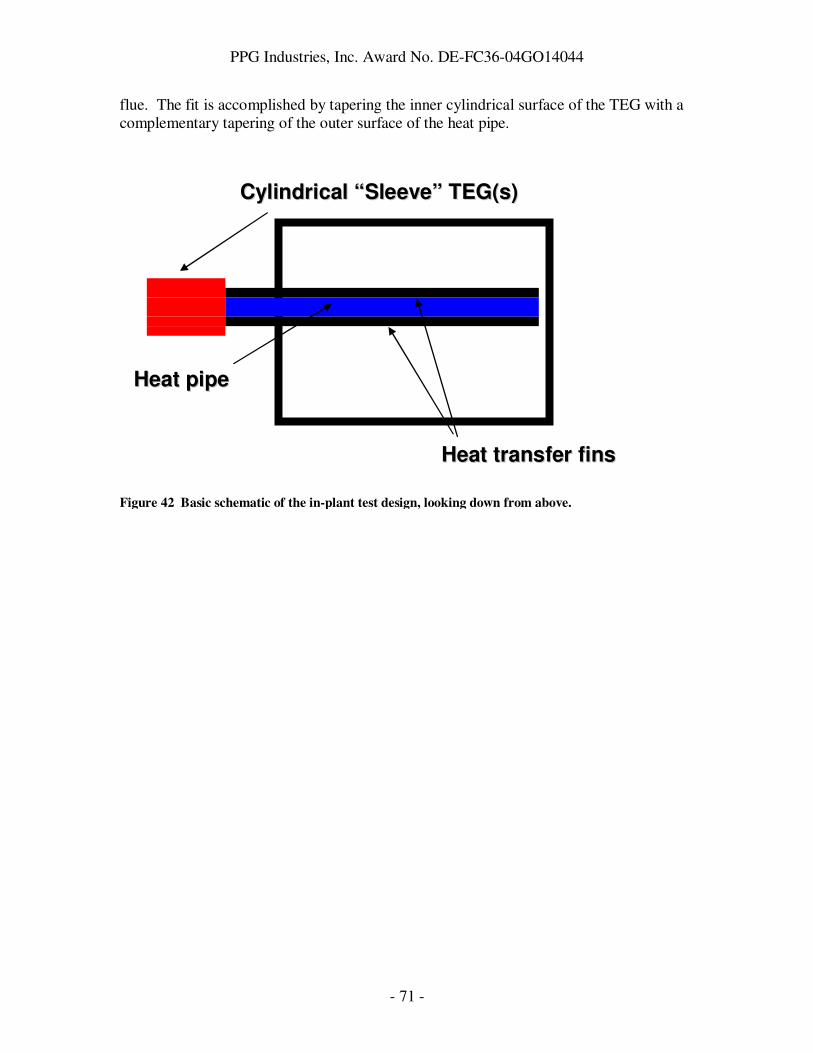
PPG Industries, Inc. Award No. DE-FC36-04GO14044
- 71 -
flue. The fit is accomplished by tapering the inner cylindrical surface of the TEG with a complementary tapering of the outer surface of the heat pipe.
Figure 42 Basic schematic of the in-plant test design, looking down from above.
CCyylliinnddrriiccaall ““SSlleeeevvee”” TTEEGG((ss))
HHeeaatt ppiippee
HHeeaatt ttrraannssffeerr ffiinnss

PPG Industries, Inc. Award No. DE-FC36-04GO14044
- 72 -
In addition to the waste heat recovery module itself (consisting of the heat pipe and the TEG), a support frame and trolley were required for the installation and removal of the module from the flue. Also, an electrical panel was required for measuring the electrical power produced by the TEG. PPG worked with a number of companies to execute the in-plant test. The heat pipe was designed and built by Thermacore (Lancaster, PA). Thermacore, PPG, and Global Thermoelectric worked together on the design and execution of the tapered fit between TEG and heat pipe. After verifying the electrical performance of a Model 7120 TEG, Global machined the taper on the inner cylindrical surface and sent the TEG to Thermacore so that Thermacore could match the taper on the heat pipe to the taper on the TEG. In addition to tapering and TEG electrical testing, Global provided an engineer who was present during start-up of the in-plant test to ensure that the TEG was brought up to operating conditions safely. River Consulting (Pittsburgh, PA) was contracted to design the support frame and trolley, and Carlson Manufacturing (Carnegie, PA) built the support frame and trolley. The electrical panel was designed by PPG, and built by Premier Automation (Monroeville, PA). Local contractors near the Meadville plant were engaged to install the support frame and trolley, the cooling water plumbing for the water jacket used to cool the outside surface of the TEG, and the installation of the electrical panel and connection to the TEG.
Figure 43 Engineering drawing of heat pipe used for the in-plant test.
An engineering drawing of the heat pipe is shown in Figure 43. The heat pipe was supported on both ends by brackets, and extended across the entire length (roughly 10

PPG Industries, Inc. Award No. DE-FC36-04GO14044
- 73 -
feet) of the flue. Thermocouples were attached at 6 locations on the heat pipe surface for diagnostic purposes.
Figure 44 Drawing of in-plant test site. This view is looking downtank (i.e. in the direction of glass motion). The downcomer is shown to the left, with the heat pipe extending at an angle across the
downcomer. The external support structure used to support the heat pipe and move it in and out of
the flue is shown above and behind the man.
The in-plant test site is shown schematically in Figure 44. Not shown in the Figure is the support that was placed in the middle of the heat pipe during installation in the flue. This support was added due to concerns about thermal stresses on the heat pipe during installation. After heat pipe installation, the support was moved back along the overhead support bar and folded for storage. In Figure 45, a photograph of the support structure is shown after installation of the heat pipe, including the folded support.

PPG Industries, Inc. Award No. DE-FC36-04GO14044
- 74 -
Before discussing the results of the in-plant trial in detail, it is worth noting that an important (and unforeseen) delay that we encountered while preparing for the trial was finding a Department of Transportation – approved method to ship the heat pipe from Thermacore to PPG Meadville. It was necessary to build special wooden crates and subject them to DOT approved testing before shipping the heat pipe. The main reason for this was the large size of the heat pipe and the fact that it contained sodium metal. Typical sodium heat pipes sold by Thermacore are smaller in size and can be shipped in 55-gallon drums. After successfully completing the shipping container testing and certification in mid-January 2008, the heat pipe manufacturer shipped the heat pipe to Works – 8 Meadville, PA. In late January 2008 the heat pipe was delivered to the plant. At that time plans were implemented to install the heat pipe and TEG. On February 4, 2008 we (PPG team and plant personnel, engineer from Global Thermoelectric, and workers from the piping, electrical, and mechanical contractors) completed the final installation of the support frame, heat pipe mounting, electrical and cooling water connections. At that time we slowly (to avoid thermal shock and to let the TEG output settle out) inserted the heat pipe into the bottom of the downstream right furnace flue. Upon installation, we began to see TEG open circuit voltage climb steadily. We blocked holes in the flue in order to raise the temperature around the heat pipe to see if we could achieve maximum TEG output. We achieved 301W of output (23.9 Amps at 12.6V) with
Figure 45 Photograph of in-plant test site, showing overhead support bar (blue) and the support
used to minimize stress to the heat pipe during installation (folded back, orange) by supporting the
heat pipe from below.
Support StructureSupport Structure
TEGTEG
Support StructureSupport Structure
TEGTEG

PPG Industries, Inc. Award No. DE-FC36-04GO14044
- 75 -
open circuit voltage above 28V. This constitutes the maximum output achievable for this TEG model. After achieving maximum output, we opened holes in the flue to return the power output level to a more sustainable level (the TEG lifetime would be shortened if operated constantly at 300W). We reduced the power to 264W and set up the data acquisition system to monitor TEG output. TEG output, as well as temperature data from the thermocouples attached to the heat pipe and cooling water temperature data, were recorded until the waste heat recovery module was removed from the exhaust flue on 8 May, 2008 (see Figure 46).
A rapid and large drop in power was observed over the first week of the plant trial. We believe this was due to change in the thermal contact between the heat pipe and the TEG, or due to an internal degradation in heat pipe performance. This is evidenced by Figure 47, which shows the TEG power output decline correlating with a decline in cooling water temperature change, which in turn correlates with the amount of heat flowing through the TEG to the cooling water. However, the heat pipe temperatures, while apparently declining slightly during the steep drop in power output, recover to their initial values soon after, while the TEG power does not recover. Also, the temperature of the heat pipe surface near the TEG was 1233°F on 5 February (when the power output was still high), whereas on 28 February that temperature was 1291°F. Thus it appears that while the surface temperatures of the heat pipe did not change substantially, the amount of heat transferred to the TEG dropped by a large amount. This points to either a thermal contact problem between heat pipe and TEG or to a problem internal to the TEG.
Figure 46 Electrical power output of TEG versus time during the in-plant trial.
Power Vs. Time For TEG
0
50
100
150
200
250
300
2/3
/08 0
:00
2/5
/08 0
:00
2/7
/08 0
:00
2/9
/08 0
:00
2/1
1/0
8 0
:00
2/1
3/0
8 0
:00
2/1
5/0
8 0
:00
2/1
7/0
8 0
:00
2/1
9/0
8 0
:00
2/2
1/0
8 0
:00
2/2
3/0
8 0
:00
2/2
5/0
8 0
:00
2/2
7/0
8 0
:00
2/2
9/0
8 0
:00
3/2
/08 0
:00
3/4
/08 0
:00
3/6
/08 0
:00
3/8
/08 0
:00
3/1
0/0
8 0
:00
3/1
2/0
8 0
:00
3/1
4/0
8 0
:00
3/1
6/0
8 0
:00
3/1
8/0
8 0
:00
3/2
0/0
8 0
:00
3/2
2/0
8 0
:00
3/2
4/0
8 0
:00
3/2
6/0
8 0
:00
3/2
8/0
8 0
:00
3/3
0/0
8 0
:00
4/1
/08 0
:00
4/3
/08 0
:00
4/5
/08 0
:00
4/7
/08 0
:00
4/9
/08 0
:00
4/1
1/0
8 0
:00
4/1
3/0
8 0
:00
4/1
5/0
8 0
:00
4/1
7/0
8 0
:00
4/1
9/0
8 0
:00
4/2
1/0
8 0
:00
4/2
3/0
8 0
:00
4/2
5/0
8 0
:00
4/2
7/0
8 0
:00
4/2
9/0
8 0
:00
5/1
/08 0
:00
5/3
/08 0
:00
5/5
/08 0
:00
5/7
/08 0
:00
5/9
/08 0
:00
5/1
1/0
8 0
:00
5/1
3/0
8 0
:00
5/1
5/0
8 0
:00
Date
Pow
er
(watt
)
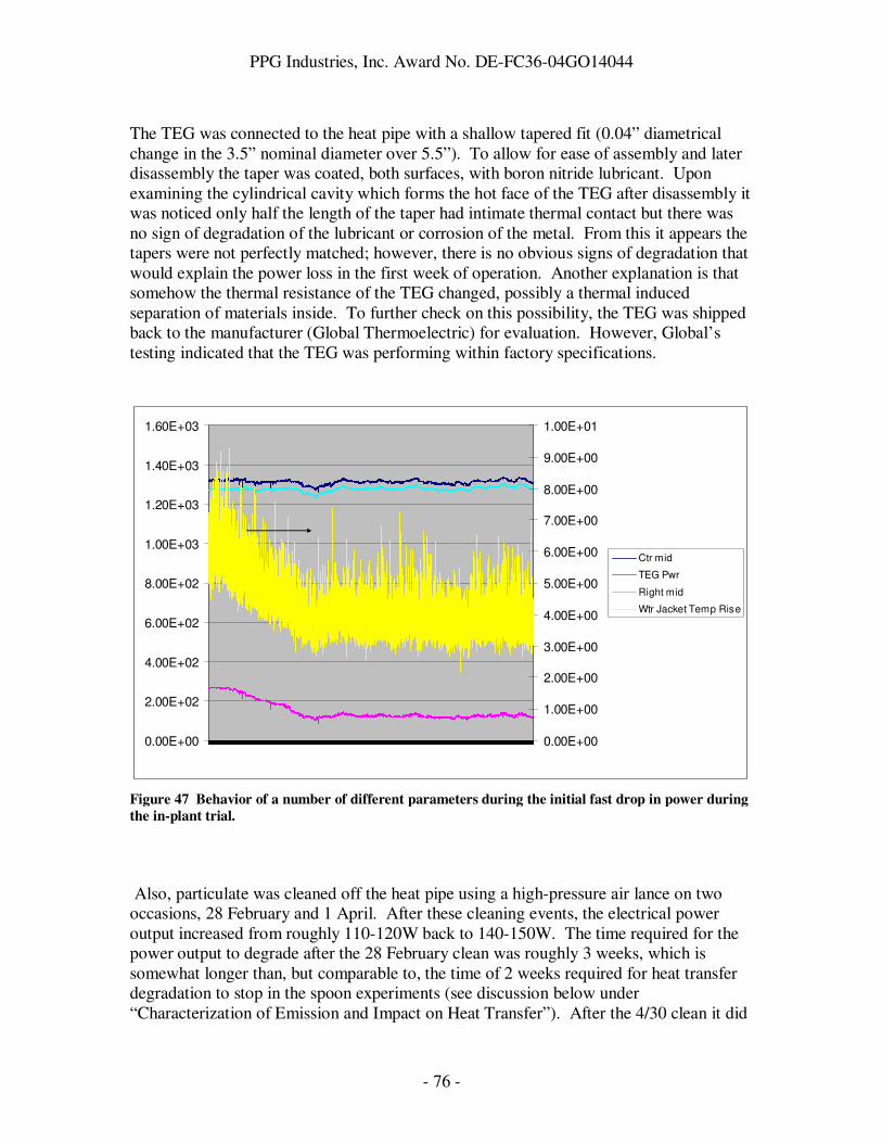
PPG Industries, Inc. Award No. DE-FC36-04GO14044
- 76 -
The TEG was connected to the heat pipe with a shallow tapered fit (0.04” diametrical change in the 3.5” nominal diameter over 5.5”). To allow for ease of assembly and later disassembly the taper was coated, both surfaces, with boron nitride lubricant. Upon examining the cylindrical cavity which forms the hot face of the TEG after disassembly it was noticed only half the length of the taper had intimate thermal contact but there was no sign of degradation of the lubricant or corrosion of the metal. From this it appears the tapers were not perfectly matched; however, there is no obvious signs of degradation that would explain the power loss in the first week of operation. Another explanation is that somehow the thermal resistance of the TEG changed, possibly a thermal induced separation of materials inside. To further check on this possibility, the TEG was shipped back to the manufacturer (Global Thermoelectric) for evaluation. However, Global’s testing indicated that the TEG was performing within factory specifications.
Also, particulate was cleaned off the heat pipe using a high-pressure air lance on two occasions, 28 February and 1 April. After these cleaning events, the electrical power output increased from roughly 110-120W back to 140-150W. The time required for the power output to degrade after the 28 February clean was roughly 3 weeks, which is somewhat longer than, but comparable to, the time of 2 weeks required for heat transfer degradation to stop in the spoon experiments (see discussion below under “Characterization of Emission and Impact on Heat Transfer”). After the 4/30 clean it did
Figure 47 Behavior of a number of different parameters during the initial fast drop in power during
the in-plant trial.
0.00E+00
2.00E+02
4.00E+02
6.00E+02
8.00E+02
1.00E+03
1.20E+03
1.40E+03
1.60E+03
0.00E+00
1.00E+00
2.00E+00
3.00E+00
4.00E+00
5.00E+00
6.00E+00
7.00E+00
8.00E+00
9.00E+00
1.00E+01
Ctr mid
TEG Pwr
Right mid
Wtr Jacket Temp Rise

PPG Industries, Inc. Award No. DE-FC36-04GO14044
- 77 -
not recover to the same level as after the 2/28 clean and the 4/1 clean. It is possible that additional buildup occurred during the interval between 4/1 and 4/30 that was not removable with air lance cleaning. On Thursday, May the 8th, the heat pipe, along with the thermoelectric generator (TEG), was removed from the flue on line 1 Meadville. Before removal a final set of operating data was retrieved. Plant personnel opened up the right side wall exposing a thick layer of molten sodium sulfate fusing the heat pipe to the wall. Two jack hammers were used to cut the molten sodium sulfate from the heat pipe. Because the sodium sulfate had built up so deep under the heat pipe it could not be removed once it was freed from the wall. The build up also prevented the insertion of the mid-span bottom support of the transport frame. Because of the Inconel construction of the heat pipe and the drop in temperature from opening up the flue it was decided that the heat pipe could be safely elevated by lengthening the two turnbuckles in the transport frame. This effectively made the heat pipe into a cantilever which once risen was easily pulled back out of the flue, clearing the deposits. During this time the water cooling was maintained to the TEG and was left on until the heat pipe was cool enough to touch. All the water and electrical connections were then disconnected. The TEG/heat pipe assembly was then unfastened from the transport frame and manually moved to rest on the shipping container. It was then decided to remove the TEG from the heat pipe in order to preserve the original approved shipping configuration of the heat pipe. The TEG was coupled to the heat pipe along a tapered fit. The taper was sprayed on both surfaces with boron nitride to prevent galling. Because of the construction of the TEG it could easily be damaged if pounding with a hammer was used to remove it thus it was decided to use a gear/bearing puller for removal. This was successful and the heat pipe was placed in the shipping container and shipped to GTC.
Economic Analysis After In-Plant Trial Based on the amount of space required by the heat pipe used in the in-plant trial, and the area of the flue we were able to block before impacting the glass production process (see “Flue Damper Experiment” described earlier under “Glass Furnace Exhaust Flue Characterization Experiments”), we believe that a practical system would use 24 heat pipes per furnace (6 per downcomer). Assuming that each heat pipe could transfer up to 15kW of heat (based on input from Thermacore), each heat pipe could in principle support 3 TEG’s (requiring 5kW each to produce 250W each). This system design was assumed for the economic analysis described below. For a 24 heat pipe system, with 3 TEG’s per heat pipe producing 250W each, a total of 18kW could be produced. This leads to a yearly energy production of 156,000 kWhr per year. Assuming 5 cents per kWhr as a typical industrial electricity charge, the yearly savings for the system would be $7800.

PPG Industries, Inc. Award No. DE-FC36-04GO14044
- 78 -
The estimated cost for a 72 TEG system on 24 heat pipes (including installation) is $970,000. Hence the payback time for this system would be 124 years, much longer than industry can support. The cost breakdown of the $970,000 is as follows: 35% Heat Pipe 22% TEG with water Jacket 17% Support Frame, Electrical & Piping materials 11% Installation 6% Engineering 9% Contingency This cost breakdown assumes that stainless steel heat pipes can be used. In our in-plant trial, we used an Inconel heat pipe due to concerns about stainless steel sagging when continuously exposed to the 1200°F flue conditions. Clearly, the major cost elements of the system are heat pipes and TEGs. Even if TEG efficiency could be increased from 5% to 100%, the payback time would still be over 6 years, which is still quite long from an industry point of view. The first point of attack for improving the economics of the module would be to find a means to capture the heat that is significantly less expensive than a heat pipe. Obviously, the economics calculated here do not show the promise of the original economics. This is due to a number of factors, including the high cost of TEGs and the high cost to capture the heat (represented by the heat pipes). Also, a much lower fraction of heat (2% versus 50% assumed earlier) is captured by the system, which limits its utility.
Characterization of Emission and Impact on Heat Transfer A number of experiments were performed in the oxyfuel furnace combustion gas exhaust flue to understand the impact of condensates in the gas stream on heat transfer to surfaces placed in the stream. These experiments included three different spoon experiments in which water- or air-cooled spoons were placed in the flue for a period of time to characterize temperature, heat flux, and/or condensate collection rate. Each experiment is discussed in some detail below. Water Cooled Block Spoon
In the first spoon experiment, a water-cooled carbon steel block was placed in the flue at the in-plant test site. None of the holes in the downcomer walls were blocked, and a

PPG Industries, Inc. Award No. DE-FC36-04GO14044
- 79 -
thermocouple placed in the gas stream measured 800°F during the testing. The block surface temperature was 200°F. The block was held in the flue for 3 1-day exposures. After each 1-day exposure, the white powder that collected on the surface was carefully brushed into a bag and weighed to determine a mass deposition rate. Finally, a 3-day exposure was performed. A deposition rate of 25 mg/day/in2 was measured. The powder composition was characterized via x-ray fluorescence (XRF) and found to be primarily sodium sulfate. Gradient Spoon The second spoon experiment was a “gradient spoon” experiment. The gradient spoon geometry is shown in Figure 48.
Existing water cooled spoon
Gradient Spoon
10
0.375
2.6875Blind hole for T/C
Cooling water in
Cooling water out
. Figure 48 Gradient spoon.
As shown in the drawing, the spoon consists of a water-cooled block with a 10” long steel plate welded to it. The plate has a blind hole drilled into it. A long rod with a thermocouple at the end of it fits snugly into the hole, and can be moved so that the temperature at various points on the plate can be measured. When the gradient spoon is inserted into the flue, a range of temperatures is realized on the steel plate. A sample temperature profile is shown in Figure 49.

PPG Industries, Inc. Award No. DE-FC36-04GO14044
- 80 -
RDTDC 3/28
0
200
400
600
800
1000
1200
0 2 4 6 8 10
Distance From Hot End of Plate
Tem
p (
F)
Figure 49 Temperature variation of gradient spoon across plate.
The block edge is 6 inches from the hot end of the plate. Thus for distances significantly greater than 6 inches, we expect the temperature to be roughly constant and low due to the effect of the cooled block. Close to the hot end of the plate, the cooling effect of the block is minimal, leading to a roughly constant and high temperature at that end. In the intermediate region between the hot and cold ends, heat is flowing via conduction at a rate governed by dQ/dt = k A dT/dx where dQ/dt is the rate of heat flow in Watts, k is the thermal conductivity in Watts/cm/K, A is the cross sectional area of the plate in cm2, and dT/dx is the temperature gradient in K/cm. Given the temperature profile data and the known cross-sectional area of the plate, and observing that k for steel is fairly constant over the 250°F – 1000°F range, it is possible to estimate the heat flow across the plate. For the profile shown above, we calculated heat transfer across the plate of 650-1300W and heat flux of 100-200W/cm2, for thermal conductivity in the range 2-4 W/cm/K. This heat transfer across the plate is related to the heat transfer from the flue environment to the plate. In addition, the gradient spoon defines a range of temperatures that is available at a given position in the flue. Finally, the gradient spoon provides the ability to study how much condensate would accumulate on a surface at a range of different temperatures at a specific location in the flue. The gradient spoon was used to characterize the Meadville flue at 3 different locations, all on the right side of the flue: the bottom of the uptank downcomer, the bottom of the downtank downcomer, and 10 feet above the bottom of the downtank downcomer. In the furnace diagram shown in Figure 50, the right uptank downcomer is labeled “RUTDC”, and the right downtank downcomer is labeled “RDTDC”.

PPG Industries, Inc. Award No. DE-FC36-04GO14044
- 81 -
Figure 50 Oxyfuel melter diagram showing right uptank downcomer (RUTDC) and right downtank
downcomer (RDTDC).
Table 9 summarizes the results of these experiments. Table 9 Data collected in first gradient spoon experiments.
Flue Location
Plate Orientation
Plate Hot End Temp
Plate Cold End Temp
Plate Heat Conduction
Total Heat Transfer
Particulate
RUTDC Bottom
Horizontal 1030°F 190°F 600-1200W
900W Collect below 600°F (4.8” from hot end)
RDTDC Bottom
Horizontal 1100 200 700-1400 1000 Collect below 700°F (4.8-5” from hot end)
RDTDC Bottom
Vertical 1070 200 700-1400
RDTDC 10 ft up
Vertical 1620 730 350-700 4000
In the table, Plate Orientation refers to whether the plane of the plate is horizontal or vertical. The Plate Hot (Cold) End Temp is the temperature of the plate at the hot (cold) end. These data show good agreement between temperatures at the bottoms of the two downcomers, and as expected much higher temperatures are seen 10 feet up the RDTDC. Plate Heat Conduction is the calculated amount of heat conducted through the plate using the calculation method described above and considering thermal conductivity values
RUTDC
RDTDC
LUTDC
LDTDC

PPG Industries, Inc. Award No. DE-FC36-04GO14044
- 82 -
between 2 and 4 W/cm/K. Again, the data are comparable at the bottom of the two downcomers. The Plate Heat Conduction 10 feet up the RDTDC is surprisingly lower than that at the bottom of the two downcomers. This could be due to a combination of factors. First, some insulation of the cooling water pipes was lost while inserting the spoon into the (narrow) slot in the downcomer, so the cooling water may have warmed significantly before entering the spoon. Second, the heat flux at that point in the downcomer is quite high, and may overwhelm the cooling power of the spoon. Upon removing the spoon from this section of the downcomer, the hottest 5 inches of the spoon were glowing red-hot, indicative of the high temperatures and heat transfer occurring in that section. Total Heat Transfer was computed by measuring the surface temperature of the cooling water in and out pipes, and using the measured water flow rate and properties of water to compute the amount of heat added to the water stream by the flue. Specifically, the formula was used, where dQ/dt is the heat transferred to the water; C is the heat capacity of water; ρ the density of water; dV/dt the volume flow rate of water; and ∆T the temperature difference measured between the two pipes. This calculation overestimates the amount of heat actually transferred to the spoon, since it includes heat transferred to the cooling water pipes as they conduct the cooling water to and from the spoon. The total heat transfer numbers are fairly consistent between RUTDC and RDTDC, and a much higher heat transfer is seen 10 feet up in the RDTDC, consistent with the higher temperatures at that location. Finally, it was noted that particulate did not collect on the hottest 5 inches of the gradient spoon when placed at the bottom of the 2 downcomers, even after 16 hours of exposure. The hottest 5 inches of the spoon had temperatures above 600F or 700F for the RUTDC and RDTDC, respectively. Additional gradient spoon experiments were performed at Meadville. An estimate of the impact of insulating the water cooling pipes to the spoon was made. Temperature profiles and particulate collection were studied for short (1/2-1 hour) exposures at three different flue locations to verify the initial results discussed above. To estimate the impact of insulating the water cooling pipes to the spoon, the spoon was inserted into the bottom of the right down tank downcomer without any insulation over the cooling pipes. The temperatures of the inlet and outlet cooling pipes were measured. Using the formula
we found that the non-insulated cooling pipes plus spoon absorbed roughly 2500W from the exhaust stream. After applying a new layer of insulation to the pipes, the device absorbed 600W from the exhaust stream. Given that the spoon length is roughly 1/5 of the total length inserted into the flue, and the other 4/5 is the cooling pipes, and assuming
Tdt
dVC
dt
dQ∆= ρ
Tdt
dVC
dt
dQ∆= ρ

PPG Industries, Inc. Award No. DE-FC36-04GO14044
- 83 -
that the insulation eliminated heat transfer to the cooling pipes, this ratio can be roughly explained based on the ratio of areas exposed to the exhaust stream. Also, given that the cooled water block on the spoon had a temperature of 200°F, and the temperature of the pipe outside the flue was 100°F, we estimate that the average temperature in the cooling water pipes is around 150°F. Given the dimensions of the tubes, and knowing the gas temperature in this region to be around 1000°F, we can estimate a heat transfer coefficient in this region without insulation, and find h ~ 60 W/m2/K. However, it is clear that it is important to minimize the length of exposed cooling water pipe to minimize the amount of stray heat transferred to the cooling water, and that insulation can dramatically improve this situation. These observations would be most relevant for a boom-type design. The following results were obtained in the second round of gradient spoon experiments. Table 10 Results of second round of gradient spoon experiments.
Flue Location
Plate Orientation
Plate Hot End Temp
Plate Cold End Temp
Total Heat Transfer
Particulate
RDTDC Bottom
Horizontal 1130 200 600W Collect below 700°F (4.8-5” from hot end)
RDTDC 10 ft up
Vertical 1680 300 3000 Collect below 650°F (5.5-6” from hot end)
Right Connecting Flue
Horizontal 770 150 300 Collect below 400°F (5” from hot end); collect differently above 400F?
The hot end temperatures obtained are quite similar for the two data sets. However, the cold end temperature is significantly lower for RDTDC 10ft up, and the total heat transfer is reduced for both RDTDC bottom and RDTDC 10 ft up. We believe this is due to much better insulation on the cooling water pipes during this quarter’s experiments. Also, while the emissions collected between 5” from the hot end and 10” from the hot

PPG Industries, Inc. Award No. DE-FC36-04GO14044
- 84 -
end were the same, easily removed white powder for each location, the surface between the hot end and 5” from the hot end was different at the three locations. For RDTDC 10 ft up, the surface was roughened and slightly charred, and indeed was glowing red hot upon removal from the flue. For RDTDC bottom, the surface was clean and undamaged. For right connecting flue, the surface seemed to have a thin, difficult-to-remove white film on it. Fortunately, the right connecting flue area is not under consideration for the current in-plant test, but if different TEGs involving lower temperature materials are used, the character of deposition there will become more important. Some pictures of the spoon are shown below.
Figure 51 Gradient spoon after removal from right connecting flue before cleaning with brush and
scraping region between hot end and 6” from hot end.

PPG Industries, Inc. Award No. DE-FC36-04GO14044
- 85 -
Figure 52 Gradient spoon after removal from right connecting flue and after cleaning with brush
and scraping region between hot end and 6” from hot end.
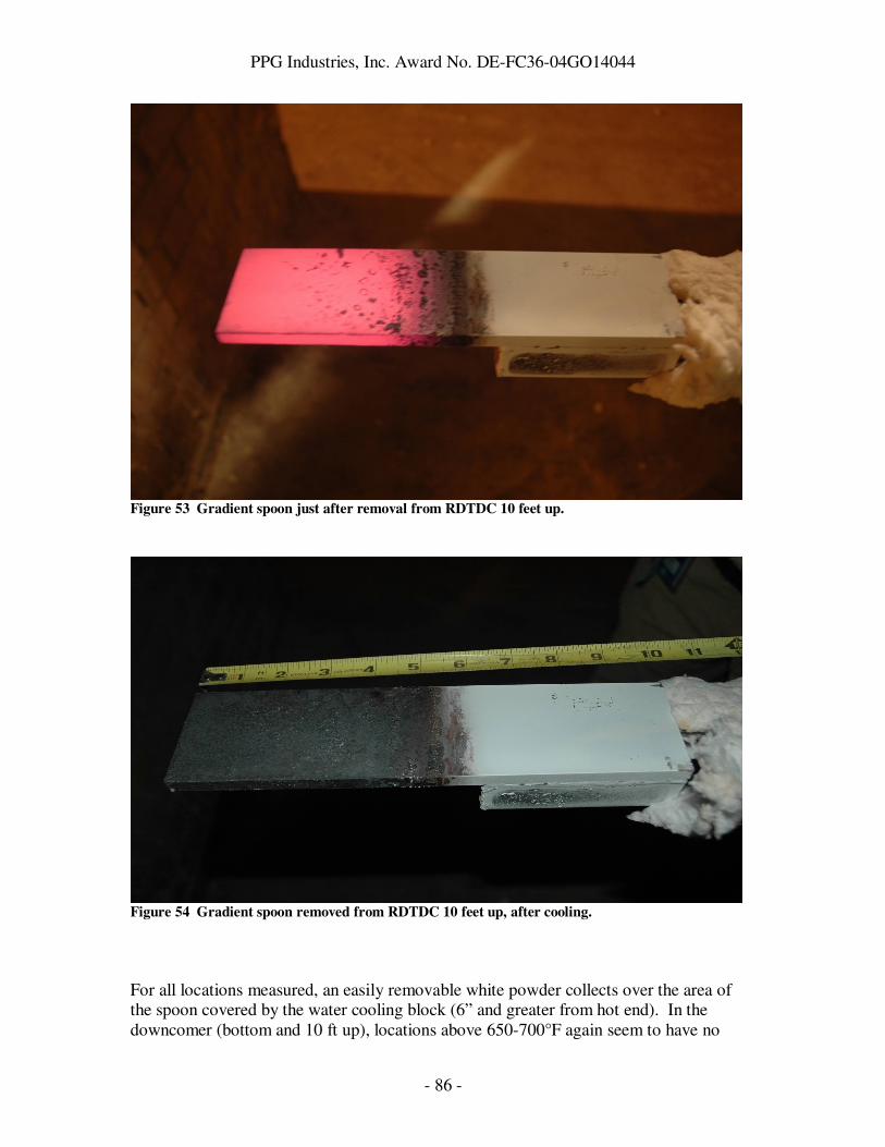
PPG Industries, Inc. Award No. DE-FC36-04GO14044
- 86 -
Figure 53 Gradient spoon just after removal from RDTDC 10 feet up.
Figure 54 Gradient spoon removed from RDTDC 10 feet up, after cooling.
For all locations measured, an easily removable white powder collects over the area of the spoon covered by the water cooling block (6” and greater from hot end). In the downcomer (bottom and 10 ft up), locations above 650-700°F again seem to have no

PPG Industries, Inc. Award No. DE-FC36-04GO14044
- 87 -
particulate collected. In the connecting flue, locations above 400°F seem to have a more tenacious film deposited on them that is difficult to remove. Materials Testing Spoon
In Run 1 of the Materials Testing Spoon (Run 0 was described above as part of the In-Plant Test report), a HFT obtained from ITI34 was cemented to the top surface of the spoon and placed in the exhaust stream at around 1100°F gas temperature, 850°F spoon top surface temperature, for twelve days. The HFT survived this exposure, and a reduction in thermal conductance from the gas to the spoon surface was observed over this time. At the end of the twelve day test, white powder particulate was cleaned off the top surface and collected, and the thermal conductance measured to return to its original value after removal of the white powder. The experiment is explained in detail below. Run 1: The major change from Run 0 to Run 1 was to switch from the Thermonetics HFT to the ITI Model HT-50 HFT. The ITI HFT is encased in stainless steel, and was therefore hoped to be more robust than the Thermonetics. Also, the ITI HFT has a K-type thermocouple integrated into it, which gives a direct measure of temperature at the surface of the spoon, in addition to the measurement of the spoon internal temperature (Tint). In addition, we dropped the measurement of heat transferred to the cooling air, and removed the insulation from the cooling air pipes. The ITI Model HT-50 HFT is a ¾” diameter and 1/8” high Gardon gauge-type transducer inside a stainless steel case, welded to a 1” diameter stainless steel flange. The wiring as received from ITI was long enough to extend out of the flue and to the data acquisition board. The ITI HFT was cemented to the top surface of the spoon using Sauereisen Aluseal Adhesive Cement #2. After drying overnight, the cement was further dried at 140°F for 6.5 hours. The HFT calibration constant did not depend on temperature, and was 18.59 BTU/hr/ft2/µV, significantly (70 times) less sensitive than the Thermonetics HFT. The configuration of the spoon as used in this experiment was shown in Figure 33 and Figure 34 above. Kaowool was again used to insulate all surfaces of the spoon except for the top surface, so that the heat flux measured by the spoon would be primarily through the top surface and would be absorbed by the cooling air impinging on the top surface. Again, insulation was not applied over the inlet and outlet air pipes in this experiment. The objectives of this run were:
1. Compare performance of ITI HFT versus Thermonetics. However, temperature would not be elevated by plugging downcomer holes in this experiment, in order to increase the chances of the HFT surviving the entire experiment.
2. Measure heat flux and compare to heat flux required for heat pipe module.
3. Demonstrate impact of condensate on heat transfer, and quantify.

PPG Industries, Inc. Award No. DE-FC36-04GO14044
- 88 -
The ITI HFT remained firmly fixed to the spoon throughout Run 1. Also, the integrity of all wires was good throughout the run. Part of this was due to the more robust design of the ITI HFT, but part was also due to maintaining normal flue conditions and not plugging holes. While this does not exactly simulate the conditions desired for the in-plant demonstration, it was shown to be possible to introduce a 300°F temperature gradient between the gas stream and internal thermocouples (using 3.3scfm of air), and the heat transfer properties are not expected to change greatly between the gas stream temperature used in this experiment (around 1130°F) and that expected for the in-plant demonstration (1472°F). As described in more detail below, heat fluxes measured with the clean (i.e. without particulate on the surface) ITI HFT were on average 3700 BTU/hr/ft2, with gas stream temperature around 1110°F, internal spoon temperature 850°F, and HFT thermocouple temperature 870°F. The temperature difference here between gas stream and spoon is 260°F. For similar temperature difference with the Thermonetics HFT, heat flux of 4257 BTU/hr/ft2 was measured (“plug 13 0” experiment). However, given uncertainties in the Thermonetics HFT contact to the spoon at that point, it is suspect at best to compare numbers between the two HFTs. If we assume the Thermonetics was still in good contact during the “plug 19” experiment, and reduce that heat flux proportionately for a 260°F temperature difference rather than the measured 308°F, we find 7700 BTU/hr/ft2 from the Thermonetics HFT. Assuming the 7700 BTU/hr/ft2 number is closer to the real value for the Thermonetics, there is a large discrepancy between the ITI and Thermonetics measurements. This discrepancy could be attributed to differences in furnace conditions, but we do not know of any significant differences in furnace conditions between Run 0 and Run 1. It could be attributed to differences in spoon geometry for the two experiments. However, the only major difference is the use of insulation on the air pipes for Run 0 versus no insulation on the air pipes for Run 1, and this seems unlikely to have a major impact on the heat flux to the HFT. Another possibility is a difference in radiant heat transfer to the two HFTs, given that the ITI HFT is made of stainless steel and so is expected to have a lower emissivity than the Thermonetics HFT, which has a glass frit coating. This difference in HFT emissivity seems like the most reasonable explanation, especially given the high intensity of red (and certainly infrared) light from the furnace that will be seen by a HFT at the bottom of the downcomer. Since the HFT was the only calibrated sensor available for measuring absolute heat flux, we used data taken from the HFT to quantify heat flux available for the in-plant test (objective 2). Three separate measurements were done with the spoon in a clean or nearly-clean state (i.e. no particulate collected). The result from these measurements was 3.7 +/- 0.3 kBTU/hr/ft2, well in excess of the 1966 BTU/hr/ft2 computed requirement for the in-plant test. These measurements were taken while measuring thermal conductance to the spoon, as described below. The spoon was left in the downcomer for twelve days to collect particulate and to monitor changes in heat flux over an extended exposure. The readings from the heat flux transducer showed a surprising amount of variation, and discontinuous jumps when data
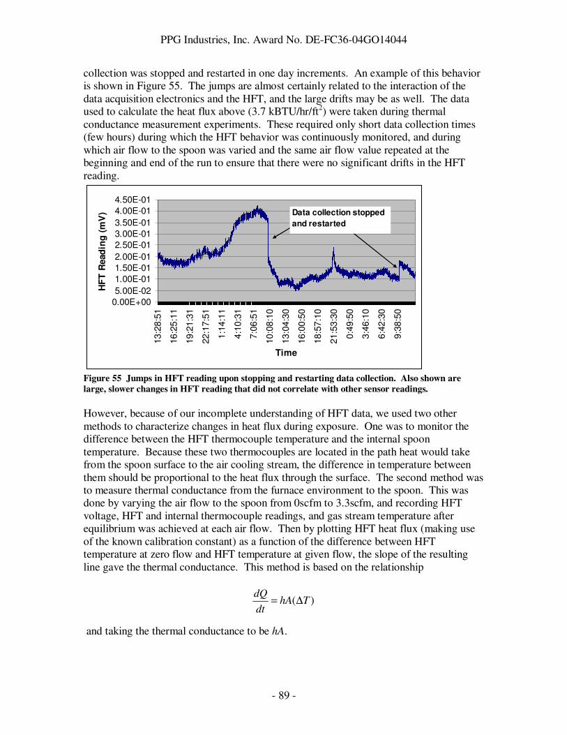
PPG Industries, Inc. Award No. DE-FC36-04GO14044
- 89 -
collection was stopped and restarted in one day increments. An example of this behavior is shown in Figure 55. The jumps are almost certainly related to the interaction of the data acquisition electronics and the HFT, and the large drifts may be as well. The data used to calculate the heat flux above (3.7 kBTU/hr/ft2) were taken during thermal conductance measurement experiments. These required only short data collection times (few hours) during which the HFT behavior was continuously monitored, and during which air flow to the spoon was varied and the same air flow value repeated at the beginning and end of the run to ensure that there were no significant drifts in the HFT reading.
0.00E+00
5.00E-02
1.00E-01
1.50E-01
2.00E-01
2.50E-01
3.00E-01
3.50E-01
4.00E-01
4.50E-01
13:2
8:5
1
16:2
5:1
1
19:2
1:3
1
22:1
7:5
1
1:1
4:1
1
4:1
0:3
1
7:0
6:5
1
10:0
8:1
0
13:0
4:3
0
16:0
0:5
0
18:5
7:1
0
21:5
3:3
0
0:4
9:5
0
3:4
6:1
0
6:4
2:3
0
9:3
8:5
0
Time
HF
T R
ead
ing
(m
V) Data collection stopped
and restarted
Figure 55 Jumps in HFT reading upon stopping and restarting data collection. Also shown are
large, slower changes in HFT reading that did not correlate with other sensor readings.
However, because of our incomplete understanding of HFT data, we used two other methods to characterize changes in heat flux during exposure. One was to monitor the difference between the HFT thermocouple temperature and the internal spoon temperature. Because these two thermocouples are located in the path heat would take from the spoon surface to the air cooling stream, the difference in temperature between them should be proportional to the heat flux through the surface. The second method was to measure thermal conductance from the furnace environment to the spoon. This was done by varying the air flow to the spoon from 0scfm to 3.3scfm, and recording HFT voltage, HFT and internal thermocouple readings, and gas stream temperature after equilibrium was achieved at each air flow. Then by plotting HFT heat flux (making use of the known calibration constant) as a function of the difference between HFT temperature at zero flow and HFT temperature at given flow, the slope of the resulting line gave the thermal conductance. This method is based on the relationship and taking the thermal conductance to be hA.
)( ThAdt
dQ∆=

PPG Industries, Inc. Award No. DE-FC36-04GO14044
- 90 -
Alternatively, one could plot the difference between HFT temperature and internal temperature as a function of the difference between HFT temperatures at zero and given flow, since the difference between HFT temperature and Internal temperature should be proportional to heat flux through the spoon. It was assumed in these measurements that with zero air flow, the heat flux through the spoon was zero. This assumption was borne out by the very low HFT voltages measured at zero air flow, and the less than 1F temperature difference between HFT temperature and Internal temperature at zero flow. Table 11, Figure 56, and Figure 57 below show an example of the conductance measurement.
y = -12.938x + 127.26
R2 = 0.9766
0
500
1000
1500
2000
2500
3000
3500
4000
4500
-350 -300 -250 -200 -150 -100 -50 0
HFT Temp - HFT Temp (zero flow) (F)
HF
T H
eat
Flu
x (
BT
U/h
r/ft
2)
Figure 56 Fit of data for conductance measurement with HFT heat flux.
Table 11 Data collected for conductance measurements.
Flow
(scfm)
Internal T
(F) HFT (mV)
HFT TC
(F)
Gas Strm
(F)
HFTC-Int
(F)
HFT Temp-HFT
Temp(0 flow) (F)
Corrected HFT
(mV)
Heat flux
(Btu/hr/ft2)
3.3 848 0.2016 871 1135 23 -292 0.1786 3573
0 1163 0.0230 1163 1138 1 0 0.0000 0
1.5 1000 0.1397 1013 1137 13 -151 0.1167 2334
3.3 851 0.2265 874 1128 22 -289 0.2035 4070

PPG Industries, Inc. Award No. DE-FC36-04GO14044
- 91 -
y = -0.0754x + 0.9546
R2 = 0.9993
0
5
10
15
20
25
-350 -300 -250 -200 -150 -100 -50 0
HFT Temp - HFT Temp (zero flow) (F)
HF
T T
em
p -
In
tern
al
Tem
p (
F)
Figure 57 Fit of data for "conductance" measurement using difference between HFT temperature
and internal temperature, which is proportional to heat flux.
Given these tools for monitoring the impact of condensate on heat transfer (viz. HFT voltage, thermal conductance, and temperature difference between HFT and Internal), two experiments were done to look at the impact of condensate. In the first experiment, a quantity of white powder that had collected on the floor of the downcomer was scooped up and dumped on a clean spoon. This experiment was done to show quickly whether there was an impact of particulate on heat transfer, and to quantify how much particulate generated that impact. In the second experiment, as already mentioned above, the spoon was left in the exhaust stream for 12 days and the heat flux monitored. At the beginning and end of the 12 day exposure, the thermal conductance was also measured. The spoon was pulled out after the 12 day exposure, and accumulated particulate was removed from the spoon and measured to quantify particulate deposition rate. Finally, the spoon was reinserted after cleaning, and thermal conductance and heat flux measured to verify that any changes in heat transfer were due to the accumulated particulate. The data obtained from dumping powder on the spoon are shown in Table 12. After dumping powder, the sensor readings were monitored and data recorded only after equilibrium was re-established. Table 12 Readings on various sensors before and after deliberately dumping a large quantity of
powder on the spoon. Changes are also computed.
Condition
Internal T
(F) HFT (mV) HFT TC (F)
Gas Stream T
(F)
HFT TC -
Internal T
(F)
Before Dump 849 0.187 869 1109 21
After Dump 804 0.131 816 1113 13
Change -45 -0.056 -53 4 -8 The two measures of heat flux, the HFT reading and the difference between the HFT and Internal spoon temperatures, both declined due to the powder. Also, the HFT and Internal temperatures themselves declined, indicating the powder insulated the spoon

PPG Industries, Inc. Award No. DE-FC36-04GO14044
- 92 -
from the heat of the exhaust stream. The powder directly over the HFT was observed to cover about 90% of the HFT area, and formed a layer 1/8” thick, plus or minus 50%. This layer was easily brushed off with a soft paint brush, and collected for measurement. 62mg of powder were collected. This first experiment showed a clear effect of powder on heat transfer. Also, it suggests that 62mg of powder reduces heat transfer by around 30%. As noted already above, it was difficult to use the long-term HFT readings to monitor changes in heat transfer over the entire 12 day experiment. However, the difference between HFT and Internal spoon temperatures showed a clear decrease over the experiment, indicating reduced heat transfer (see Figure 58). The size of the decrease was roughly 1/3. After removing the spoon at the end of the 12 day experiment and collecting the accumulated particulate, then reinserting the cleaned spoon, the temperature difference recovered to 24°F. This verifies that the decline in heat transfer can be attributed to the accumulation of particulate on the spoon.
1.00E+01
1.20E+01
1.40E+01
1.60E+01
1.80E+01
2.00E+01
2.20E+01
2.40E+01
2.60E+01
Time (arb)
HF
T T
C -
In
tern
al
T (
F)
Figure 58 Decline in heat flux through the spoon over the extended exposure, as measured by the
difference between HFT and Internal thermocouple temperatures.
The conductance measured using the HFT method, as well as the quantity proportional to conductance measured using the temperature difference of the HFT and Internal thermocouples, are tabulated for various exposure times in Table 13. According to both measurements, the conductance from the environment to the spoon is reduced by half over the 12 day exposure, and recovered to its original value after the particulate was brushed off of the spoon. 130mg of powder was collected from the HFT surface. Given the total exposure time of 306 hours, and the area of the spoon from which particulate was collected (the HFT itself and surrounding area), gives a collection rate of 5 mg/day/in2. This is a factor of four lower than what was measured earlier (in the very first spoon experiment, see above) on a water-cooled surface (200°F, as opposed to the 850°F of the air-cooled spoon used here), showing lower particulate collection rate on a surface closer to the temperature of the surrounding gas.

PPG Industries, Inc. Award No. DE-FC36-04GO14044
- 93 -
Table 13 Conductance from flue environment to spoon, and quantity proportional to that
conductance, as a function of exposure time. The “2 hr (after 12 day)” data were taken after
cleaning particulate from the spoon after 12 day exposure and reinserting the spoon at the same
location.
Exposure Time
HFT Conductance
(BTU/hr/ft2/F)
HFT TC - Internal T
"Conductance"
2 hr 12.2 0.065
18 hr 12.9 0.075
12 days 5.7 0.037
2 hr (after 12 day) 14.1 0.084
Summary: The major results of Run 1 are summarized below. • The heat flux available at the bottom of the downcomer should be
sufficient to power the 7120 TEG. Measurements taken with both the Thermonetics and ITI HFT’s indicated at least a factor of 2 margin over the heat flux requirement for Thermacore’s heat pipe.
• Radiant heat transfer may be very important at the bottom of the downcomer.
• Particulate collection rates are reduced as the temperature difference between surface and gas environment is reduced. 5 mg/in2/day were observed for a 300°F difference, while earlier data showed 20 mg/in2/day for a (roughly) 900°F difference.
• Particulate buildup can have a major impact on heat transfer. At this particular point in the exhaust stream, heat transfer fell by about 4% per day due to particulate buildup.
• Particulate collected on the spoon surface could be easily removed by light brushing with a soft brush.
A third run (Run 2) of the Materials Testing Spoon was also conducted. The purpose of this run was to repeat Run 1 with improved configuration of the data acquisition software in hopes of eliminating the large drifts in the HFT readings that were seen in Run 1 over time. Data collected over a 15 day run showed that the large drifts were indeed eliminated with this new configuration. After about 7 days in the flue environment, very little additional degradation in heat transfer was observed by HFT measurements. Run 2: The hardware used for Run 2 was identical to that used for Run 1, with the exception that a new (and presumably identical) data acquisition board was used.35 We enabled the “continuous calibration” feature in the data acquisition board software in hopes of eliminating the large drifts seen in the HFT data in Run 1. This feature is used specifically to eliminate drift in the analog circuitry of the board due to changes in the electrical environment or temperature of the board over time.
The objectives of this run were:
1. Confirm data taken in Run 1 for heat flux and degradation of heat flux over time at the proposed site for the in-plant demo.

PPG Industries, Inc. Award No. DE-FC36-04GO14044
- 94 -
2. Test whether the large drifts and jumps in HFT data could be reduced or eliminated.
The Materials Testing Spoon was insulated as shown in Figure 33 and inserted into the flue at the bottom of the right downtank downcomer, the proposed site of the in-plant test. Thermal conductance was measured as described above, and found to be 13.1 BTU/hr/ft2/°F. This is in good agreement with values of 12.2, 12.9, and 14.1 BTU/hr/ft2/°F measured in Run 1. The spoon was then left in the flue at that location for 14 days, and the usual data collected (internal spoon temperature, HFT temperature, HFT heat flux, and gas stream temperature). Figure 59 below shows the HFT readings in mV as a function of time over the course of the 14 day run. Clearly, these data do not show these drifts and jumps that were seen in Run 1 (see Figure 55). We attribute this to the continuous calibration feature on the data acquisition software, although we did not turn off this feature during the run to verify that it was the cause.
-1500
-1000
-500
0
500
1000
1500
2000
2500
3000
3500
4000
0 200000 400000 600000 800000 1000000 1200000 1400000
Time (sec)
Ht
Flx
(3.3
scfm
) -
Ht
Flx
(0scfm
)
(Btu
/hr/
ft2)
(HF
T)
Figure 59 Heat flux (less zero flow heat flux) as a function of time over 15 days of continuous
exposure to the flue environment at the proposed in-plant test site. No drifts or steps are observed.
The average heat flux over the first hour that the spoon was in the flue was 3026 BTU/hr/ft2. This is somewhat lower than the Run 1 result of 3.7 +/- 0.3 kBTU/hr/ft2. The average heat flux for data taken after day 7 of the experiment was 1739 BTU/hr/ft2. This represents a decrease in heat flux of nearly 40%. The maximum reduction in heat flux is about ½, judging by the upper and lower bounds of the data set. In Run 1, a reduction in heat flux of ½ was found for a 12 day exposure, based on conductance measurements. We conclude that the “clean” spoon heat flux value for Run 2 is somewhat lower than Run 1, while the reduction in heat transfer due to particulate collection in Run 2 is similar to slightly less than was measured in Run 1 using different methods. Note that all heat fluxes here did not include the heat flux with zero air flow to the spoon.

PPG Industries, Inc. Award No. DE-FC36-04GO14044
- 95 -
Run 2 of the Materials Testing Spoon continued to 28 days exposure to the flue environment at 3.3scfm air flow to the spoon. Heat flux and temperature data were collected with the heat flux transducer. The data are shown in Figure 60 below. Apparently, the heat flux stops decreasing after about 15 days flue exposure. The large drop in heat flux at the end of the run was due to a wire breaking on the HFT as it was removed from the flue.
-1500
-1000
-500
0
500
1000
1500
2000
2500
3000
3500
0 5 10 15 20 25 30
Flue Exposure Time (Days)
Ht
Flu
x (
3.3
scfm
) -
Ht
Flu
x (
0scfm
)
(Btu
/hr/
ft2)
HF
T
Figure 60 Heat flux as a function of time as measured during Run 2.
Strategies to Minimize Emissions Impact Dr. John H Johnson and his student Kiran Premchand set out to study the literature on formation and control of particulate in the glass furnace exhaust, including ways of controlling particulate formation or periodic cleaning of the surface to minimize the impact of the particulate formation on the performance of the heat pipe. Dr. John H Johnson has more than 40 years of experience working with particulate matter formation and its control as related to the mining and the automotive industry. It was proposed that a thorough study of the problem involving a literature review on the topic will reveal possible solutions. The major tasks involved in this study are summarized as follows:

PPG Industries, Inc. Award No. DE-FC36-04GO14044
- 96 -
1. Gather existing literature and information already known to PPG from PPG
personnel.
2. Perform a literature review about the chemical and physical characteristics of the particulate of interest, i.e., Na2SO4,
3. Based on the preliminary study of the particulate characteristics, perform a
literature review about means to prevent and/or control Na2SO4 particulate formation on the heat pipe,
4. With the help of available literature, come up with possible means of controlling
particulate formation or provide means of periodic cleaning of the heat pipe surface,
5. Write, review and submit a brief report (in electronic format - MSWord) about the
study to PPG industries.
6. Propose and make cost estimates for two or more 1-2 day experiments that PPG could perform in conjunction with its heat pipe / TEG test to test recommendations of the report for cleaning or controlling Na2SO4 particulate formation, and assist PPG with these experiments. Also include in the cost estimates assistance to PPG for these experiments.
The literature review concentrated in four general areas:
i. Properties of Na2SO4 and how it forms as a particulate including size distribution data,
ii. Na2SO4 particles and the methods of control, and iii. EPA New Source Standards that apply to glass manufacturing. iv. Possible materials that could be applied to the heat pipe surface that would reduce
the tendency of Na2SO4 to adhere to the heat pipe. The literature review focused on the following journals and electronic databases:
• Journal of the American Chemical Society, • Environmental Science and Technology (online journal), • Journal of the Air and Waste Management Association, • Journal of Chemical and Engineering Data, • Chemical Engineering Journal, • Environmental Sciences and Pollution Management (online database), and • Environmental Protection Agency – Standards – Information Services.
Other journals and/or databases were searched for material as and when found to be necessary. Also, relevant books were acquired and/or loaned to complete the literature review.

PPG Industries, Inc. Award No. DE-FC36-04GO14044
- 97 -
The other area of study was to come up with approaches/ideas for cleaning/preventing the formation of particles on the heat pipe. These were recorded in the brief report delivered at the end of the project. The main conclusions of the study were: • Rate of deposition of Na2SO4 is critical to degradation of heat pipe performance • Majority of degradation of heat pipe performance is expected due to change in
absorptivity of heat pipe surface (from 0.94 to 0.06-0.39) due to covering of surface with Na2SO4 , a loose white powdery deposit and change in outer surface temperature of heat pipe due to Na2SO4 particulate formation
• Online mechanical cleaning methods seem to be the most promising in restoring heat
pipe performance • Experiments can be conducted to study the effect of particulate formation on heat pipe
performance and to determine which cleaning method is most suitable and effective for restoring heat pipe performance
The full text of the report is found in Appendix I.
PPG Industries, Inc. Award No. DE-FC36-04GO14044
- 98 -
Accomplishments Although the primary objective of demonstrating waste heat recovery with 20% efficiency in an industrial process was not achieved, the project did accomplish many of the objectives that were integral to achieving the primary objective, including: • Defined a strategy (modular waste heat recovery) for implementing TE technology in
an industrial process, and suggested several possible module designs • Calculated the economics of one module, namely the heat pipe module, based on real
heat pipe, TEG, and installation costs from vendors, and demonstrated the importance of heat collection technology and TEG efficiency in those economics
• Identified a new class of thin-film TE materials and showed how they could be implemented in commercially available TEG designs
• Performed (to our knowledge) the first demonstration of high temperature waste heat recovery with TE technology in an industrial environment, using heat collection and TE technology capable of generating a significant amount of power (100W) given today’s technology
• Characterized temperatures and heat transfer in an oxyfuel glass melter exhaust system • Quantified the long-term impact of condensate buildup on heat transfer in the exhaust
system using a custom-designed spoon device • Reviewed existing knowledge of condensates in a glass furnace and existing
technology that may be useful for mitigating the impact of those condensates on heat transfer
In addition to these accomplishments, the following invention disclosures and/or patent applications were made: • “PbTe-based N-Type Thermoelectric Materials”, disclosure submitted by PNNL. • “Waste Heat Recovery with Photovoltaics”, disclosure submitted by PPG. PPG chose
not to pursue. • “Heat Pipes and Use of Heat Pipes in Furnace Exhaust”, patent application submitted
by PPG. • “A Device for Use in a Furnace Exhaust Stream for Thermoelectric Generation”, patent
application submitted by PPG. Also, the following presentation was made: “Advanced Thermoelectric Materials for Efficient Waste Heat Recovery in Process Industries”, Presented at the DOE Industrial Materials for the Future Annual Review, June 1, 2005, Chicago, IL.

PPG Industries, Inc. Award No. DE-FC36-04GO14044
- 99 -
Conclusions The primary conclusion to be drawn from this project is that TE technology is still far from ready to be used for waste heat recovery on an industrial scale. The Si/SiGe and B4C/B9C materials systems that motivated this project were found to be impractical for use in real devices. Thick film GAST material appears to show promise as a material that can achieve ZT ~ 1.5 at 300°C temperature. While this is a remarkable accomplishment in a field that has struggled to achieve ZT of 1 after 100 years of research, additional improvement in high temperature ZT is required to make an economical device. Also, while recent research has suggested that thin films and other new materials structures may lead to higher ZT materials, incorporating these new structures into a TEG may require new TEG device designs. We have demonstrated a novel technique for depositing thin films on Kapton substrates and then winding them to obtain thermoelements that could be integrated into TEG designs that currently use bulk thermoelements. However, this technique is limited to the useful temperature range of Kapton, which is 400°C or below. We successfully demonstrated that waste heat could be collected, transferred to a TEG, and converted to electricity in a real industrial process, and that this could be done for a period of at least several months with only minimal maintenance by plant personnel. This was achieved using heat pipe technology to efficiently transfer collected heat to the TEG hot surface, and relied on a relatively large heat pipe to collect a sufficient amount of heat through primarily radiative heat transfer from the hot glass furnace. The presence of condensates in the exhaust gas stream led to heat transfer reductions of about 50% after 2 weeks, but leveled off after that. The impact of particulate collection on waste heat recovery efficiency was observed, and it was found that some of the efficiency loss could be reversed by manually cleaning the heat pipe surface on a monthly basis. Commercially available, automated cleaning technologies were identified that could reduce this maintenance cycle even further. However, given current TEG costs and efficiencies, as well as current heat pipe costs, this approach to waste heat recovery is far from ready for adoption by industry.

PPG Industries, Inc. Award No. DE-FC36-04GO14044
- 100 -
Recommendations As a result of the findings of this project, we would recommend the following: • Additional basic science work on high-temperature thermoelectric materials such as
GAST, with the recognition that such work is high-risk and may require years of additional device work after benchtop demonstration of the material properties before a practical TEG with high efficiency would be realized
• Applied R&D and engineering work focused on developing inexpensive heat collection and heat transfer methods that could be applied across multiple industries
• Applied R&D work on inexpensive materials (either bulk or coatings) that would improve survivability of heat exchangers at high temperatures (>500°C)
• Exploration of alternative heat-to-electricity conversion methods with higher efficiencies than thermoelectrics

PPG Industries, Inc. Award No. DE-FC36-04GO14044
- 101 -
References 1 Mahan, G., Sales, B., and Sharp, J. Physics Today, March 1997, page 42. 2 Pellegrino, J. Glass Industry of the Future: Energy and Environmental Profile of the U.S. Glass Industry,
April 2002. Published by Office of Industrial Technologies, U.S. DOE. 3 Margolis, N. and Brindle, R. Energy Profile of the Steel Industry, August 2000. Published by Office of Industrial Technologies, U.S. DOE. 4 Choate, W. and Green, J.A.S. U.S. Energy Requirements for Aluminum Production, February 2003. Published by Office of Industrial Technologies, U.S. DOE. 5 Margolis, N. Energy Profile of the U.S. Aluminum Industry, July 1997. Published by Office of Industrial Technologies, U.S. DOE. 6 Pellegrino, J. Energy Profile for the Chemical Industry, May 2000. Published by Office of Industrial Technologies, U.S. DOE. 7 Trier, W. Glass Furnaces: Design, Construction, and Operation. Sheffield, UK: Society of Glass Technology, 1987. 8 Rowe, D.M. CRC Handbook of Thermoelectrics. Introduction. Boca Raton: CRC, 1995. 9 Hicks, L.D. and Dresselhaus, M.S. Physical Review B 47, 12727 (1993). 10 Venkatasubramanian, R., Silvola, E., Colpitts, T., and O’Quinn, B. Nature 413, 597 (2001). 11 Hsu, K.F. et al. Science 303, 818 (2004). 12 Goldsmid, H.J. CRC Handbook of Thermoelectrics, Chapter 3. Boca Raton: CRC, 1995. 13 Sales, B.C., Mandrus, D., Willaims, R.K. Science 272, 1325 (1996). 14 Nolas, G.S., et al. J. Appl. Phys. 79, 4002 (1996). 15 Chen, N. et al. Appl Phys. Lett. 87, 171903 (2005). 16 Skrabek, E.A. and Trimmer, D.S. CRC Handbook of Thermoelectrics, Chapter 22. Boca Raton: CRC, 1995. 17 Khinkis, M. Ya., et al. Steklo i Keramika 1, 15 (1968). 18 Shapiro, M.D. Tyurin, A.I., and Lashenkov, Yu. V. Steklo i Keramika 11, 24 (1980). 19 Nycz, J.A. and Sturgill, D.T. The Glass Industry, June 1980, p. 12. 20 Rozendaal, N.A. Glass International December 2007 / January 2008, p. 32. 21 Kobayashi, et al. Ceramic Engineering and Science Proceedings 26, 1 (2005). 22 Kobayashi, et al. Glass Problems Conference Energy Workshop. October 2005, Champaign IL. 23 Glass Manufacturing Industry Council. Glass Melting Technology: A Technical and Economic
Assessment. October 2004. 24http://www.hi-z.com/hz20.php 25 Enerac Inc., Westbury, NY. 26 Dwyer Instruments Inc., Michigan City, IN. 27 Setra Systems Inc., Boxborough, MA. 28 Kumar, V., Gangacharyulu, D., and Tathgir, R.G. Heat Transfer Engineering 28 954 (2007), and references therein. 29 Rosenfeld, J.H. and Ernst, D.M. Heat Pipe Science and Technology: Proc. 11
th Int. Heat Pipe Conf.,
Tokyo-Japan 1999, p 407. 30 Thermonetics Corp., La Jolla, CA 31 Sauereisen Cements Company, Pittsburgh, PA. 32 Thermal Ceramics, Augusta, GA. 33 HiE Coat 840-M, Aremco Products, Inc. 34 International Thermal Instrument Co., Del Mar, CA. 35 Personal DAQ/56. IOTech, Cincinnati, OH.
APPENDIX I ,-./0 o2 -34 536768-479:-98: 6;/ 5o;-7ol o2 ,o/9.= ,.l26-4 )67-98.l6-4 56>4 !o7=6-9o; o; 6 ?46- )9@4 A:4/ 2o7 (;47g0 '48oC470 27o= -34 (D36.:- E6: o2 6 El6:: F6;.268-.79;g !.7;684 !
!
!
!
!"#$%"#&'%(&')*+,-..#&'+/0'
1"2'345('6'345()4('"#$$!%&'()*!+(,*!-.('*!/012340)5!67!8!9::;"!<*=>!?:$@A!9BCD@9";!E&F>!?:$@A!9BCDG"##!
!H!!
7-"%('8'!"#,95%(&'!
!
!
!
I1)*!;$5!C$$B!
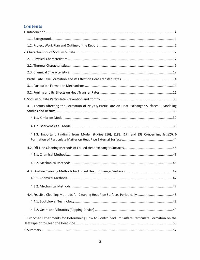
C!!
!"#$%#$&'"J!7)4.0,1K4(0)!JJJJJJJJJJJJJJJJJJJJJJJJJJJJJJJJJJJJJJJJJJJJJJJJJJJJJJJJJJJJJJJJJJJJJJJJJJJJJJJJJJJJJJJJJJJJJJJJJJJJJJJJJJJJJJJJJJJJJJJJJJJJJJJJJJJJJJJJJJJJJJJ!9!
"J"J!L&KM2.01),!JJJJJJJJJJJJJJJJJJJJJJJJJJJJJJJJJJJJJJJJJJJJJJJJJJJJJJJJJJJJJJJJJJJJJJJJJJJJJJJJJJJJJJJJJJJJJJJJJJJJJJJJJJJJJJJJJJJJJJJJJJJJJJJJJJJJJJJJJ!9!
"JCJ!N.0O*K4!P0.M!N=&)!&),!Q14=()*!0R!43*!%*S0.4!JJJJJJJJJJJJJJJJJJJJJJJJJJJJJJJJJJJJJJJJJJJJJJJJJJJJJJJJJJJJJJJJJJJJJJJJJJJJJJJJJJJJ!#!
CJ!T3&.&K4*.(U4(KU!0R!+0,(1V!+1=R&4*!JJJJJJJJJJJJJJJJJJJJJJJJJJJJJJJJJJJJJJJJJJJJJJJJJJJJJJJJJJJJJJJJJJJJJJJJJJJJJJJJJJJJJJJJJJJJJJJJJJJJJJJJJJJJJJ!G!
CJ"J!N3WU(K&=!T3&.&K4*.(U4(KU!JJJJJJJJJJJJJJJJJJJJJJJJJJJJJJJJJJJJJJJJJJJJJJJJJJJJJJJJJJJJJJJJJJJJJJJJJJJJJJJJJJJJJJJJJJJJJJJJJJJJJJJJJJJJJJJJJJJJJJ!G!
CJCJ!<3*.V&=!T3&.&K4*.(U4(KU!JJJJJJJJJJJJJJJJJJJJJJJJJJJJJJJJJJJJJJJJJJJJJJJJJJJJJJJJJJJJJJJJJJJJJJJJJJJJJJJJJJJJJJJJJJJJJJJJJJJJJJJJJJJJJJJJJJJJJJ!:!
CJ;J!T3*V(K&=!T3&.&K4*.(U4(KU!JJJJJJJJJJJJJJJJJJJJJJJJJJJJJJJJJJJJJJJJJJJJJJJJJJJJJJJJJJJJJJJJJJJJJJJJJJJJJJJJJJJJJJJJJJJJJJJJJJJJJJJJJJJJJJJJJJ!"C!
;J!N&.4(K1=&4*!T&M*!E0.V&4(0)!&),!(4U!XRR*K4!0)!/*&4!<.&)UR*.!%&4*U!JJJJJJJJJJJJJJJJJJJJJJJJJJJJJJJJJJJJJJJJJJJJJJJJJJJJJJJJJ!"9!
;J"J!N&.4(K1=&4*!E0.V&4(0)!6*K3&)(UVU!JJJJJJJJJJJJJJJJJJJJJJJJJJJJJJJJJJJJJJJJJJJJJJJJJJJJJJJJJJJJJJJJJJJJJJJJJJJJJJJJJJJJJJJJJJJJJJJJJ!"9!
;JCJ!E01=()2!&),!(4U!XRR*K4U!0)!/*&4!<.&)UR*.!%&4*UJJJJJJJJJJJJJJJJJJJJJJJJJJJJJJJJJJJJJJJJJJJJJJJJJJJJJJJJJJJJJJJJJJJJJJJJJJJJJJJJJ!"@!
9J!+0,(1V!+1=R&4*!N&.4(K1=&4*!N.*'*)4(0)!&),!T0)4.0=!JJJJJJJJJJJJJJJJJJJJJJJJJJJJJJJJJJJJJJJJJJJJJJJJJJJJJJJJJJJJJJJJJJJJJJJJJJJJJJJ!;$!
9J"J! E&K40.U!YRR*K4()2! 43*! E0.V&4(0)!0R!Z&C+Q9! N&.4(K1=&4*! 0)!/*&4! XFK3&)2*.! +1.R&K*U! 8!60,*=()2!+41,(*U!&),!%*U1=4U!JJJJJJJJJJJJJJJJJJJJJJJJJJJJJJJJJJJJJJJJJJJJJJJJJJJJJJJJJJJJJJJJJJJJJJJJJJJJJJJJJJJJJJJJJJJJJJJJJJJJJJJJJJJJJJJJJJJJJJJJJJJJJJJJJ!;$!
9J"J"J![(.M\.(,*!60,*=!JJJJJJJJJJJJJJJJJJJJJJJJJJJJJJJJJJJJJJJJJJJJJJJJJJJJJJJJJJJJJJJJJJJJJJJJJJJJJJJJJJJJJJJJJJJJJJJJJJJJJJJJJJJJJJJJJJJJJJJJJ!;$!
9J"JCJ!L**.M*)U!*4!&=J!60,*=JJJJJJJJJJJJJJJJJJJJJJJJJJJJJJJJJJJJJJJJJJJJJJJJJJJJJJJJJJJJJJJJJJJJJJJJJJJJJJJJJJJJJJJJJJJJJJJJJJJJJJJJJJJJJJJJ!;@!
9J"J;J! 7VS0.4&)4! E(),()2U! R.0V! 60,*=! +41,(*U! ]"@^5! ]"B^5! ]"G^! &),! ];^! T0)K*.)()2! GHIJKL!E0.V&4(0)!0R!N&.4(K1=&4*!6&44*.!0)!/*&4!N(S*!XF4*.)&=!+1.R&K*U!JJJJJJJJJJJJJJJJJJJJJJJJJJJJJJJJJJJJJJJJJJJJJJJJJJJJJJJ!99!
9JCJ!QRRD_()*!T=*&)()2!6*430,U!0R!E01=*,!/*&4!XFK3&)2*.!+1.R&K*U!JJJJJJJJJJJJJJJJJJJJJJJJJJJJJJJJJJJJJJJJJJJJJJJJJJJJJJ!9@!
9JCJ"J!T3*V(K&=!6*430,U!JJJJJJJJJJJJJJJJJJJJJJJJJJJJJJJJJJJJJJJJJJJJJJJJJJJJJJJJJJJJJJJJJJJJJJJJJJJJJJJJJJJJJJJJJJJJJJJJJJJJJJJJJJJJJJJJJJJJJ!9@!
9JCJCJ!6*K3&)(K&=!6*430,U!JJJJJJJJJJJJJJJJJJJJJJJJJJJJJJJJJJJJJJJJJJJJJJJJJJJJJJJJJJJJJJJJJJJJJJJJJJJJJJJJJJJJJJJJJJJJJJJJJJJJJJJJJJJJJJJJJ!9@!
9J;J!Q)D_()*!T=*&)()2!6*430,U!R0.!E01=*,!/*&4!XFK3&)2*.!+1.R&K*U!JJJJJJJJJJJJJJJJJJJJJJJJJJJJJJJJJJJJJJJJJJJJJJJJJJJJJ!9G!
9J;J"J!T3*V(K&=!6*430,U!JJJJJJJJJJJJJJJJJJJJJJJJJJJJJJJJJJJJJJJJJJJJJJJJJJJJJJJJJJJJJJJJJJJJJJJJJJJJJJJJJJJJJJJJJJJJJJJJJJJJJJJJJJJJJJJJJJJJJ!9G!
9J;JCJ!6*K3&)(K&=!6*430,U!JJJJJJJJJJJJJJJJJJJJJJJJJJJJJJJJJJJJJJJJJJJJJJJJJJJJJJJJJJJJJJJJJJJJJJJJJJJJJJJJJJJJJJJJJJJJJJJJJJJJJJJJJJJJJJJJJ!9G!
9J9J!E*&U(\=*!T=*&)()2!6*430,U!R0.!T=*&)()2!/*&4!N(S*!+1.R&K*U!N*.(0,(K&==W!JJJJJJJJJJJJJJJJJJJJJJJJJJJJJJJJJJJJJJJ!9B!
9J9J"J!+004\=0`*.!<*K3)0=02W!JJJJJJJJJJJJJJJJJJJJJJJJJJJJJJJJJJJJJJJJJJJJJJJJJJJJJJJJJJJJJJJJJJJJJJJJJJJJJJJJJJJJJJJJJJJJJJJJJJJJJJJJJJJJJ!9B!
9J9JCJ!a*&.U!&),!b(\.&40.U!?%&SS()2!-*'(K*A!JJJJJJJJJJJJJJJJJJJJJJJJJJJJJJJJJJJJJJJJJJJJJJJJJJJJJJJJJJJJJJJJJJJJJJJJJJJJJJJJJJJJJJ!9:!
#J!N.0S0U*,!XFS*.(V*)4U!R0.!-*4*.V()()2!/0`!40!T0)4.0=!+0,(1V!+1=R&4*!N&.4(K1=&4*!E0.V&4(0)!0)!43*!/*&4!N(S*!0.!40!T=*&)!43*!/*&4!N(S*!JJJJJJJJJJJJJJJJJJJJJJJJJJJJJJJJJJJJJJJJJJJJJJJJJJJJJJJJJJJJJJJJJJJJJJJJJJJJJJJJJJJJJJJJJJJJJJJJJJJJJJJJJJJJ!#$!
@J!+1VV&.W!JJJJJJJJJJJJJJJJJJJJJJJJJJJJJJJJJJJJJJJJJJJJJJJJJJJJJJJJJJJJJJJJJJJJJJJJJJJJJJJJJJJJJJJJJJJJJJJJJJJJJJJJJJJJJJJJJJJJJJJJJJJJJJJJJJJJJJJJJJJJJJJJJ!#G!

;!!
%*R*.*)K*U!JJJJJJJJJJJJJJJJJJJJJJJJJJJJJJJJJJJJJJJJJJJJJJJJJJJJJJJJJJJJJJJJJJJJJJJJJJJJJJJJJJJJJJJJJJJJJJJJJJJJJJJJJJJJJJJJJJJJJJJJJJJJJJJJJJJJJJJJJJJJJJJJJJJ!#B!
YSS*),(F!Y>!+&VS=*!_*44*.!&),!P.(4*D1S!40!T0VS&)(*U!43&4!N.0'(,*!/*&4!XFK3&)2*.!E01=()2!<.*&4V*)4!Xc1(SV*)4d+*.'(K*U!JJJJJJJJJJJJJJJJJJJJJJJJJJJJJJJJJJJJJJJJJJJJJJJJJJJJJJJJJJJJJJJJJJJJJJJJJJJJJJJJJJJJJJJJJJJJJJJJJJJJJJJJJJJJJJJJJJJJJJJJJJJJJJJJJJJJ!@$!
YJ"J!_*44*.!L0,W!JJJJJJJJJJJJJJJJJJJJJJJJJJJJJJJJJJJJJJJJJJJJJJJJJJJJJJJJJJJJJJJJJJJJJJJJJJJJJJJJJJJJJJJJJJJJJJJJJJJJJJJJJJJJJJJJJJJJJJJJJJJJJJJJJJJJJJJ!@$!
YJCJ!N.0\=*V!-*UK.(S4(0)!JJJJJJJJJJJJJJJJJJJJJJJJJJJJJJJJJJJJJJJJJJJJJJJJJJJJJJJJJJJJJJJJJJJJJJJJJJJJJJJJJJJJJJJJJJJJJJJJJJJJJJJJJJJJJJJJJJJJJJJJ!@$!
YJ;J!_(U4!0R!T0VS&)(*U!<3&4!N.0'(,*!/*&4!XFK3&)2*.!T=*&)()2!+*.'(K*U!d!N.0,1K4U!d!Xc1(SV*)4!]"9^!JJ!@C!
YSS*),(F!L>!_(U4!0R!+01.K*U!eU*,!R0.!P.(4()2!<3(U!%*S0.4!JJJJJJJJJJJJJJJJJJJJJJJJJJJJJJJJJJJJJJJJJJJJJJJJJJJJJJJJJJJJJJJJJJJJJJJJJJ!@9!
LJ"J!Y!_(U4!0R!I01.)&=U!0R!7)4*.*U4!?eS,&4*,!=&U4!0)!"CdC$dC$$GAJJJJJJJJJJJJJJJJJJJJJJJJJJJJJJJJJJJJJJJJJJJJJJJJJJJJJJJJJJJJ!@9!
LJCJ!Y!_(U4!0R!L00MU!H!N&S*.U!?eS,&4*,!=&U4!0)!$Cd""dC$$BA!JJJJJJJJJJJJJJJJJJJJJJJJJJJJJJJJJJJJJJJJJJJJJJJJJJJJJJJJJJJJJJJJJ!@@!
YSS*),(F!T>!Y,,(4(0)&=!E(21.*U!&),!<&\=*U!T0)4&()()2!N.0S*.4(*U!0R!+0,(1V!+1=R&4*!-*S0U(4!JJJJJJJJJJJJJJJJJJ!G$!
YSS*),(F!->!N&.&V*4.(K!Xc1&4(0)U!-*V0)U4.&4()2!T3&)2*!()!/*&4!<.&)UR*.!%&4*U!40!43*!/*&4!N(S*!,1*!40!Z&C+Q9!N&.4(K1=&4*!E0.V&4(0)!JJJJJJJJJJJJJJJJJJJJJJJJJJJJJJJJJJJJJJJJJJJJJJJJJJJJJJJJJJJJJJJJJJJJJJJJJJJJJJJJJJJJJJJJJJJJJJJJJJJJJJJJJJJJJJJJJJJJJ!G;!
T&U*!7!8!/*&4!S(S*!U1.R&K*!(U!K=*&)!?)0!,*S0U(4A!JJJJJJJJJJJJJJJJJJJJJJJJJJJJJJJJJJJJJJJJJJJJJJJJJJJJJJJJJJJJJJJJJJJJJJJJJJJJJJJJJJJJJJ!G;!
T&U*!77!8!Z&C+Q9!,*S0U(4!0R!43(KM)*UU!MNOP!(U!R0.V*,!0)!43*!3*&4!S(S*!U1.R&K*!JJJJJJJJJJJJJJJJJJJJJJJJJJJJJJJJJJ!G#!
YSS*),(F! X>! %*US0)U*U! 40! X)c1(.W! _*44*.! ?()! YSS*),(F! YA! R.0V! N04*)4(&=! +1SS=(*.U! 0R! /*&4! XFK3&)2*.!E01=()2!T0)4.0=!Xc1(SV*)4!JJJJJJJJJJJJJJJJJJJJJJJJJJJJJJJJJJJJJJJJJJJJJJJJJJJJJJJJJJJJJJJJJJJJJJJJJJJJJJJJJJJJJJJJJJJJJJJJJJJJJJJJJJJJJJJJJJJJJJJJJ!GG!
!

9!!
()'*#$+",-.$/"#'!
<3(U! .*S0.4! ,*UK.(\*U! &! U41,W! K0),1K4*,! 0)! &'&(=&\=*! .*U*&.K3! =(4*.&41.*! &\014! Z&C+Q9! S&.4(K1=&4*!S.0S*.4(*U!&),!R0.V&4(0)!`3(K3!=*&,U!40!R01=()2!0R!43*!014*.!U1.R&K*U!0R!&!3*&4!S(S*!()4*),*,!R0.!1U*!()!43*!*F3&1U4!R=1*!,1K4!0R!&!R=&4D2=&UU!V&)1R&K41.()2!R1.)&K*!&U!S&.4!0R!&!3*&4!.*K0'*.W!UWU4*VJ!
()()'01.23+"-#,'E=&4D2=&UU!(U!0)*!0R!43*!()4*.V*,(&4*!S.0,1K4U!43&4!NNa!V&)1R&K41.*U!&4!43*!S=&)4!()!6*&,'(==*5!NYJ!NNa!3&U!4`0!R1.)&K*U!8!&!.*2*)*.&4('*!4WS*!R1.)&K*!&),!&)!0FWDR1*=!R1.)&K*J!7)!&!.*2*)*.&4('*!4WS*!R1.)&K*5!&(.!(U!1U*,!&U!43*!0F(,&)4!R0.!K0V\1U4(0)!`3*.*&U!()!43*!0FWDR1*=!R1.)&K*5!0FW2*)!(U!1U*,!()U4*&,!0R!&(.!&U!43*!0F(,&)4J!<3*!R1.)&K*!43&4!(U!0R!()4*.*U4!40!43(U!S.0O*K4!(U!43*!0FWDR1*=!R1.)&K*J!!
XF3&1U4!2&U!R.0V!43*!0FWDR1*=!R1.)&K*!*F(4U!43.0123!'*.4(K&=!,1K4U!K&==*,!f,0`)K0V*.Ug5!)1V\*.()2!4`0!0)!*&K3!U(,*!0R!43*! =()*5!0)*!*&K3! R.0V!43*! f1S4&)Mg!&),!43*! f,0`)4&)MgJ!-0`)K0V*.! =*)243U! R0.! 43(U!R1.)&K*!&.*!&SS.0F(V&4*=W!"G!R45!&),!43*U*!V*.2*!()40!&!K0))*K4()2!R=1*!@J#!R4!\W!:J;!R4!&),!.0123=W!@$!R4!=0)25!K0))*K4()2!43*!,0`)K0V*.U!40!43*!U4&KMJ!<3*!O1)K4(0)!0R!43*!,0`)K0V*.!40!43*!K0))*K4()2!R=1*!(U!43*!&.*&!`3*.*!43*!3*&4!S(S*! (U!S=&))*,!40!\*!S=&K*,J!E.0V!()(4(&=!V*&U1.*V*)4U!0\4&()*,!R.0V!NNa5!43(U! &.*&! 3&U! &! 4*VS*.&41.*! .&)2*! 0R! #$$DG$$! hT5! `3*.*&U! 43*! 2&U! 4*VS*.&41.*U! &4! 43*! 40S! 0R! 43*!,0`)K0V*.U!3&'*!\**)!V*&U1.*,!40!\*!&SS.0F(V&4*=W!"#$$!hTJ!<3*!S.*UU1.*!()!43*!K0))*K4()2!R=1*!(U!U=(234=W!=*UU!43&)!&4V0US3*.(K!S.*UU1.*J!Y=U05!43*.*!&.*!UV&==!0S*)()2U!()!43*!K0))*K4()2!R=1*!`3(K3!=*4!&4V0US3*.(K!&(.!*)4*.! 43*!R=1*!43.0123!43*!0S*)()2U!'(&!)&41.&=!,.&R45! 43*.*\W!&UU(U4()2! ()!K00=()2!43*!R=1*!2&UJ!
<3*!3*&4!S(S*!(U!&!U=*),*.!KW=(),.(K&=!V*4&=!?7)K0)*=A!S(S*!`(43!&!=(c1(,!V*4&=!?U0,(1VA!R(==*,!()U(,*!43*!S(S*J! 74! &=U0! 3&U! 4`0! =&4*.&=! R()U! &44&K3*,! =*)243D`(U*! 40! 4`0! ,(&V*4.(K&==W! 0SS0U(4*! U(,*U! 0)! 43*!KW=(),.(K&=!S(S*J!P3(=*! ()!0S*.&4(0)5!43*U*!R()U!`(==!\*!S=&K*,!30.(i0)4&==W5!&U!43*!S.(V&.W!3*&4!4.&)UR*.!V*K3&)(UV!`(==!\*!.&,(&4(0)!R.0V!43*!R1.)&K*!&\0'*!43*!3*&4!S(S*J!<3*!<Xa!&),!43*!R1.)&K*!R=1*!,1K4U!&.*!,*UK.(\*,!()!V0.*!,*4&(=!()!YSS*),(F!YJ!YSS*),(F!Y!&=U0!,*UK.(\*U!43*!=*44*.!40!S04*)4(&=!U1SS=(*.U!0R!3*&4!*FK3&)2*.!R01=()2!K0)4.0=!*c1(SV*)4!&),!43*!*)K=0U1.*!`(43!43*!=*44*.!,*UK.(\()2!43*!R1.)&K*!R=1*!&),!43*!<XaJ!
Y)!(VS0.4&)4!(UU1*!43&4!)**,U!40!\*!&,,.*UU*,!`3*)!&44*VS4()2!40!.*K0'*.!3*&4!*)*.2W!R.0V!43*!R=1*!2&U*U!(U!43*!R01=()2!0R!43*!3*&4!4.&)UR*.!U1.R&K*U!0R!43*!3*&4!S(S*J!E.0V!&)!()(4(&=!()US*K4(0)!0R!43*!R=1*5!43*!R0.V&4(0)!0R!&!`3(4*!S0`,*.W!,*S0U(4!`&U!0\U*.'*,!40!4&M*!S=&K*J!<3(U!S0`,*.W!S&.4(K1=&4*!V&44*.!`&U! ,*4*.V()*,! 40! \*! U0,(1V! U1=R&4*! ?Z&C+Q9A5! R.0V! &)&=WU*U! K0),1K4*,! \W! NNaJ! +0,(1V! U1=R&4*5!*US*K(&==W!()!(4U!S0`,*.!R0.V!(U!&!S00.!K0),1K40.!0R!3*&4!&),!`(==!K&1U*!,*4*.(0.&4(0)!0R!43*!3*&4!S(S*!S*.R0.V&)K*!0'*.!4(V*J!!
<3*!X)'(.0)V*)4&=!N.04*K4(0)!Y2*)KW!?XNYA!3&U!.*21=&4*,!43*!404&=!S&.4(K1=&4*!*V(UU(0)!.&4*U!R.0V!)*`!2=&UU!V&)1R&K41.()2!S=&)4UJ!<3*!U4&),&.,U!&.*!2('*)!()!%*R*.*)K*!]"^5!&),!<&\=*!"!2('*U!&!K0VS&.(U0)!0R!

#!!
S&.4(K1=&4*!*V(UU(0)!.&4*U!?V*&U1.*,!()!2.&VU!0R!S&.4(K1=&4*!S*.!M(=02.&VU!0R!2=&UU!S.0,1K*,A!R0.!'&.(01U!U*2V*)4U!0R!43*!2=&UU!V&)1R&K41.()2!(),1U4.WJ!!
:%+;#'<0'=!>'?.%(&%"&)'@'!%".-9*;%.#'#,-))-4('"%.#)'!"#$%#&'()*+,-')./0"#$%#"-'11#&($2,+.23#A4"'B;%))',%(*A%9.*"-(B'$;%(.)'C<D'
Glass manufacturing plant industry Segment
Furnace fired with gaseous fuel!
Furnace fired with liquid fuel
T0)4&()*.!2=&UU! $J"! $J";!
N.*UU*,!&),!\=0`)!2=&UU! ! !
?&A L0.0U(=(K&4*!.*K(S*U! $J#! $J@#!
?\A +0,&D_(V*!&),!_*&,!.*K(S*U! $J"! $J";!
?KA Q43*.! 43&)! L0.0U(=(K&4*5! +0,&D_(V*! &),! _*&,! .*K(S*U! ?()K=1,()2!0S&=5!R=10.(,*!&),!043*.!.*K(S*UA!
$JC#! $J;C#!
P00=!R(\*.2=&UU! $JC#! $J;C#!
E=&4!2=&UU! $JCC#! $JCC#!
!
<3(U! .*S0.4!S.0'(,*U!&)!1),*.U4&),()2!0R!S&.4(K1=&4*! R0.V&4(0)!0)!3*&4!*FK3&)2*.! U1.R&K*U! &),!`&WU!&),!V*&)U!40!S.*'*)4!&),d0.!K0)4.0=! (4J!<3*!.*S0.4!U122*U4U!V*430,U!40!K=*&)!43*!3*&4!S(S*!U1.R&K*U!&),!S.0'(,*U!.*R*.*)K*UdK0)4&K4U! ()! 43*! (),1U4.W! 43&4!K&)!\*!0R!&UU(U4&)K*! ()!S.0'(,()2!*c1(SV*)4! R0.!43*!S.*'*)4(0)dK=*&)()2!S.0K*UU*UJ!!
()4)'5+"6%.$'7"+2'581#'1#,'9-$8/#%'":'$;%'<%="+$'<3*!R0==0`()2!&.*!43*!US*K(R(K!4&UMU!43&4!`*.*!K&..(*,!014! ()!&KK0.,&)K*!`(43!43*!NNadI03)!/!I03)U0)!K0)4.&K4J!
"J a&43*.!*F(U4()2!=(4*.&41.*!&),!()R0.V&4(0)!&=.*&,W!M)0`)!40!NNa!R.0V!NNa!S*.U0))*=5!CJ N*.R0.V!&! =(4*.&41.*! .*'(*`! &\014! 43*! K3*V(K&=! &),!S3WU(K&=! K3&.&K4*.(U4(KU!0R! 43*! S&.4(K1=&4*!0R!
()4*.*U45!(J*J5!Z&C+Q95!;J L&U*,!0)!43*!S.*=(V()&.W!U41,W!0R!43*!S&.4(K1=&4*!K3&.&K4*.(U4(KU5!S*.R0.V!&!=(4*.&41.*!.*'(*`!&\014!
V*&)U!40!S.*'*)4!&),d0.!K0)4.0=!Z&C+Q9!S&.4(K1=&4*!R0.V&4(0)!0)!43*!3*&4!S(S*5!9J P(43! 43*! 3*=S! 0R! &'&(=&\=*! =(4*.&41.*5! K0V*! 1S! `(43! S0UU(\=*! V*&)U! 0R! K0)4.0==()2! S&.4(K1=&4*!
R0.V&4(0)!0.!S.0'(,*!V*&)U!0R!S*.(0,(K!K=*&)()2!0R!43*!3*&4!S(S*!U1.R&K*5!!#J P.(4*5!.*'(*`!&),!U1\V(4!&!\.(*R!.*S0.4!?43(U!,0K1V*)4!D!()!*=*K4.0)(K!R0.V&4!D!6+P0.,A!&\014!43*!
U41,W!40!NNa!(),1U4.(*U5!&),!@J N.0S0U*!&),!V&M*!K0U4!*U4(V&4*U!R0.!4`0!0.!V0.*!"DC!,&W!*FS*.(V*)4U!43&4!NNa!K01=,!S*.R0.V!()!
K0)O1)K4(0)! `(43! (4U! 3*&4! S(S*d<Xa! 4*U45! 40! 4*U4! .*K0VV*),&4(0)U! 0R! 43*! .*S0.4! R0.! K=*&)()2! 0.!K0)4.0==()2!Z&C+Q9! S&.4(K1=&4*! R0.V&4(0)5! &),! &UU(U4! NNa!`(43! 43*U*! *FS*.(V*)4UJ! Y=U0! ()K=1,*! ()!43*!K0U4!*U4(V&4*U!&UU(U4&)K*!40!NNa!R0.!43*U*!*FS*.(V*)4UJ!
!
@!!
YSS*),(F!L!K0)4&()U!43*!,*4&(=U!0R!43*!=(4*.&41.*!.*'(*`!R0.!(4*VU!"D9!&\0'*J!Y!.&4()2!UWU4*V!R.0V!"D"$!?"!8!=0`*U4!&),!"$!8!3(23*U4A!`&U!1U*,!40!.&4*!43*!U(2)(R(K&)K*!0R!'&.(01U!S&S*.Ud\00MUJ!N&S*.Ud\00MU!43&4!`*.*! .&4*,! &U! #!0.! &\0'*!`*.*! 1U*,! 40!`.(4*! 43(U! .*S0.4! &),! 43*W! &.*! =(U4*,! ()! 43*! f%*R*.*)K*Ug!U*K4(0)!&4! 43*!*),!0R! 43(U! .*S0.4J! +*K4(0)!C! ()! 43(U! .*S0.4! K0)4&()U! 43*!S3WU(K&=5! 43*.V&=!&),!K3*V(K&=!S.0S*.4(*U! 0R! Z&C+Q9! R.0V! 43*! =(4*.&41.*5! R0==0`*,! \W! U*K4(0)! ;! `3(K3! K0)4&()U! &! ,(UK1UU(0)! 0)!S&.4(K1=&4*!K&M*!R0.V&4(0)!&),!(4U!*RR*K4U!0)!43*!3*&4!4.&)UR*.!.&4*UJ!<3*!&SS.0&K3*U!R0.!S.*'*)4(0)!&),!K0)4.0=!0R!Z&C+Q9! S&.4(K1=&4*!V&44*.! &.*! K0)4&()*,! ()! U*K4(0)! 9J! Y=U05! YSS*),(F! T! K0)4&()U! &,,(4(0)&=!4&\=*U!43&4!&.*!.*R*.*)K*,!R.0V!`(43()!U*K4(0)U!0R!43*!V&()!\0,W!0R!43(U!,0K1V*)4J!+*K4(0)!#!K0)4&()U!&!,*UK.(S4(0)!0R!*FS*.(V*)4U!43&4!K&)!\*!K0),1K4*,!\W!NNa!40!,*4*.V()*!43*!0S4(V&=!K=*&)()2!V*430,!R0.!43*!3*&4!S(S*!1U*,!R0.!3*&4!.*K0'*.W!0R!R=1*!2&U*U!R.0V!43*!2=&UU!R1.)&K*J!E()&==W5!U*K4(0)!@!U1VV&.(i*U!01.!R(),()2U!R.0V!43(U!U41,WJ!
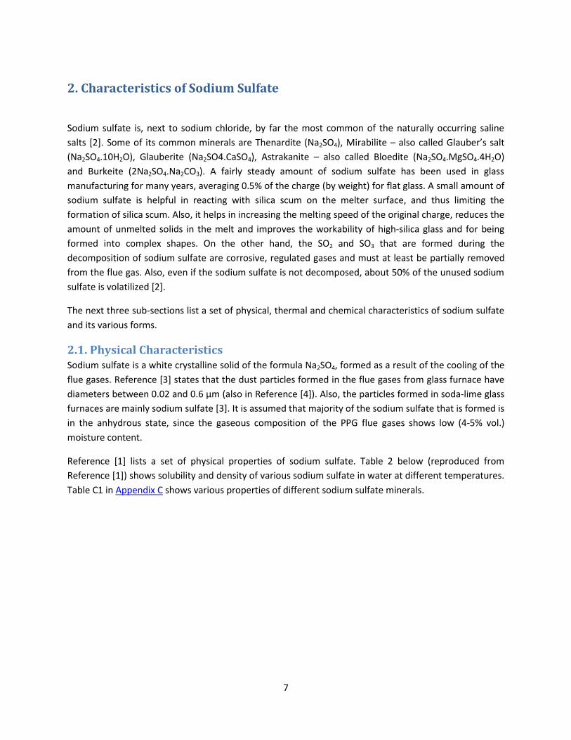
G!!
4)'!;1+1.$%+/&$/.&'":'>",/-?'>-8:1$%'!
+0,(1V!U1=R&4*! (U5! )*F4! 40! U0,(1V!K3=0.(,*5!\W! R&.! 43*!V0U4! K0VV0)!0R! 43*!)&41.&==W!0KK1..()2! U&=()*!U&=4U! ]C^J!+0V*!0R! (4U!K0VV0)!V()*.&=U!&.*!<3*)&.,(4*! ?Z&C+Q9A5!6(.&\(=(4*!8!&=U0!K&==*,!a=&1\*.gU!U&=4!?Z&C+Q9J"$/CQA5! a=&1\*.(4*! ?Z&C+Q9JT&+Q9A5! YU4.&M&)(4*! 8! &=U0! K&==*,! L=0*,(4*! ?Z&C+Q9J62+Q9J9/CQA!&),! L1.M*(4*! ?CZ&C+Q9JZ&CTQ;AJ! Y! R&(.=W! U4*&,W! &V01)4! 0R! U0,(1V! U1=R&4*! 3&U! \**)! 1U*,! ()! 2=&UU!V&)1R&K41.()2!R0.!V&)W!W*&.U5!&'*.&2()2!$J#j!0R!43*!K3&.2*!?\W!`*(234A!R0.!R=&4!2=&UUJ!Y!UV&==!&V01)4!0R!U0,(1V! U1=R&4*! (U! 3*=SR1=! ()! .*&K4()2! `(43! U(=(K&! UK1V! 0)! 43*! V*=4*.! U1.R&K*5! &),! 431U! =(V(4()2! 43*!R0.V&4(0)!0R!U(=(K&!UK1VJ!Y=U05!(4!3*=SU!()!()K.*&U()2!43*!V*=4()2!US**,!0R!43*!0.(2()&=!K3&.2*5!.*,1K*U!43*!&V01)4!0R!1)V*=4*,!U0=(,U! ()! 43*!V*=4!&),! (VS.0'*U! 43*!`0.M&\(=(4W!0R!3(23DU(=(K&!2=&UU!&),! R0.!\*()2!R0.V*,! ()40! K0VS=*F! U3&S*UJ! Q)! 43*! 043*.! 3&),5! 43*! +QC! &),! +Q;! 43&4! &.*! R0.V*,! ,1.()2! 43*!,*K0VS0U(4(0)!0R!U0,(1V!U1=R&4*!&.*!K0..0U('*5!.*21=&4*,!2&U*U!&),!V1U4!&4!=*&U4!\*!S&.4(&==W!.*V0'*,!R.0V!43*!R=1*!2&UJ!Y=U05!*'*)!(R!43*!U0,(1V!U1=R&4*!(U!)04!,*K0VS0U*,5!&\014!#$j!0R!43*!1)1U*,!U0,(1V!U1=R&4*!(U!'0=&4(=(i*,!]C^J!!
<3*!)*F4!43.**!U1\DU*K4(0)U!=(U4!&!U*4!0R!S3WU(K&=5!43*.V&=!&),!K3*V(K&=!K3&.&K4*.(U4(KU!0R!U0,(1V!U1=R&4*!&),!(4U!'&.(01U!R0.VUJ!
4)()'5;@&/.18'!;1+1.$%+/&$/.&'+0,(1V!U1=R&4*!(U!&!`3(4*!K.WU4&==()*!U0=(,!0R!43*!R0.V1=&!Z&C+Q95!R0.V*,!&U!&!.*U1=4!0R!43*!K00=()2!0R!43*!R=1*!2&U*UJ!%*R*.*)K*!];^!U4&4*U!43&4!43*!,1U4!S&.4(K=*U!R0.V*,!()!43*!R=1*!2&U*U!R.0V!2=&UU!R1.)&K*!3&'*!,(&V*4*.U!\*4`**)!$J$C!&),!$J@!kV!?&=U0!()!%*R*.*)K*!]9^AJ!Y=U05!43*!S&.4(K=*U!R0.V*,!()!U0,&D=(V*!2=&UU!R1.)&K*U!&.*!V&()=W!U0,(1V!U1=R&4*!];^J!74!(U!&UU1V*,!43&4!V&O0.(4W!0R!43*!U0,(1V!U1=R&4*!43&4!(U!R0.V*,!(U!()! 43*! &)3W,.01U! U4&4*5! U()K*! 43*! 2&U*01U! K0VS0U(4(0)! 0R! 43*! NNa! R=1*! 2&U*U! U30`U! =0`! ?9D#j! '0=JA!V0(U41.*!K0)4*)4J!
%*R*.*)K*! ]"^! =(U4U! &! U*4! 0R! S3WU(K&=! S.0S*.4(*U! 0R! U0,(1V! U1=R&4*J! <&\=*! C! \*=0`! ?.*S.0,1K*,! R.0V!%*R*.*)K*!]"^A!U30`U!U0=1\(=(4W!&),!,*)U(4W!0R!'&.(01U!U0,(1V!U1=R&4*!()!`&4*.!&4!,(RR*.*)4!4*VS*.&41.*UJ!<&\=*!T"!()!YSS*),(F!T!U30`U!'&.(01U!S.0S*.4(*U!0R!,(RR*.*)4!U0,(1V!U1=R&4*!V()*.&=UJ!
!
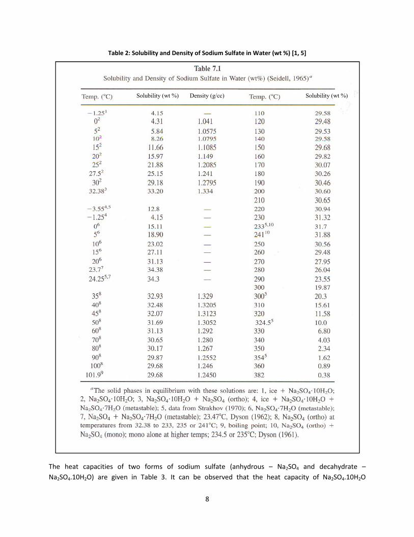
B!!
:%+;#'E0'?4;*+-;-./'%(&'1#()-./'4A'?4&-*,'?*;A%.#'-('F%.#"'GH.'IJ'C<K'LD'
!
<3*! 3*&4! K&S&K(4(*U! 0R! 4`0! R0.VU! 0R! U0,(1V! U1=R&4*! ?&)3W,.01U! 8! Z&C+Q9! &),! ,*K&3W,.&4*! 8!Z&C+Q9J"$/CQA! &.*! 2('*)! ()! <&\=*! ;J! 74! K&)! \*! 0\U*.'*,! 43&4! 43*! 3*&4! K&S&K(4W! 0R! Z&C+Q9J"$/CQ!
Solubility (wt %) Density (g/cc) Solubility (wt %)

:!!
?,*K&3W,.&4*A! (U! BD:! 4(V*U! 3(23*.! 43&)! 43&4! R0.! Z&C+Q9! ?&)3W,.01UA! &4! 43*! U&V*! 4*VS*.&41.*J! <3*!,*K&3W,.&4*!=0U*U!`&4*.!&4!"$$lT!40!R0.V!43*!&)3W,.01U!R0.V!&),!43*!&)3W,.01U!R0.V!V*=4U!&4!B99lTJ!
:%+;#'M0'6#%.'8%$%9-./'4A'N%E?OP'%(&'N%E?OP2<Q6EO'C<D'
:'G7J' 8$'G9%;R,4;#27J' :'G7J' 8$'G9%;R,4;#27J'
N%E?OP' N%E?OP2<Q6EO' ' N%E?OP' N%E?OP2<Q6EO'
"#! $JCCC! "J:9$! :$! "9J99$! #$J:G$!
C$! $J#B"! 9JC$$! "$$! "#J:;$! #@J":$!
C#! "JC";! GJ;$$! "C$! "BJ9#$! @#J:;$!
;$! "J::$! "$J#;$! "9$! C$J#$$! G#J"$$!
;#! CJ:B$! ";J:@$! "@$! CCJC#$! B;J@B$!
9$! 9J$GG! "GJ#"$! "B$! C;JBC$! :"J#9$!
9#! #JCCC! C"J"B$! C$$! C#JC;$! ::J"B$!
#$! @J9C;! C9J:#$! CC$! C@J#"$! "$@JB$$!
@$! BJG9;! ;CJ;B$! C9$! CGJ@G$! ""9JG$$!
G$! "$JB#$! ;:JC#$! C@$! CBJG;$! "CCJ:$$!
B$! "CJG@$! 9#J9;$! CB$! C:J@G$! ";"J9$$!
! ! ! ;$$! ;$J#"$! "9$J#$$!
!
Y)043*.!U*4!0R!.*=*'&)4!,&4&!R0.!U0,(1V!U1=R&4*!(U!43*!U*4!0R!43*.V0,W)&V(K!S.0S*.4(*U!U30`)!()!<&\=*!9J!
:%+;#'P0':5#",4&/(%,-9'S%;*#)'4A'N%E?OP'C<D'
=(.5%;$/'!0+'-/"#4$-5#67893'4A' T"##'=(#"B/'
'!0+'-/"#4$-3'
=(."4$/''
!+'-/8#"#4$-3#T4",%.-4(' T*)-4(' ?4;*.-4('
D;;$J:! m#JB;! m$JCB! D;$;J9! ;#JG!
!
4)4)'A;%+?18'!;1+1.$%+/&$/.&'<3*.V&=!K0),1K4('(4W!0R!U0,(1V!U1=R&4*! (U!&)043*.! (VS0.4&)4!S.0S*.4W! 43&4! (U! .*c1(.*,! R0.!K&=K1=&4(0)U!=&4*.!()!43(U!.*S0.4J!Y=430123!43*!.*R*.*)K*U!43&4!`*.*!.*'(*`*,!&U!S&.4!0R!43(U!U41,W!,0!)04!K(4*!'&=1*U!

"$!!
R0.! 43*! 43*.V&=! K0),1K4('(4W! 0R! Z&C+Q95! %*R*.*)K*! ]@^! 2('*U! &! .&)2*! 0R! '&=1*U! R0.! 43*! 43*.V&=!K0),1K4('(4W!0R!)0)DV*4&==(K! U0=(,U!&U!:;<#=#>:!"#$%&J!%*R*.*)K*! ]G^! K(4*U! 43*!43*.V&=!K0),1K4('(4W!0R!U0,(1V! 43(0U1=R&4*! ?Z&C+CQ;J! #/CQA! &U! ?;<>! "#$%&! &4! '()! &! ?''*+A5! &),! 43*! 43*.V&=! K0),1K4('(4W! 0R!U0,(1V!3W,.02*)!U1=R&4*!?Z&/+Q9A!&U!.&)2()2!R.0V!:;#>6>!"#$%&!&4!,,-!&!./01*+2! 40!:;7?7!"#$%&!&4!)/3!&!.',)*+2!&U!U30`)!()!<&\=*!#J!
:%+;#'L0':5#",%;'94(&*9.-S-./'4A')4&-*,'5/&"4B#(')*;A%.#'GN%6?OPJ'%.'S%"-4*)'.#,$#"%.*"#)'CUD'
:#,$#"%.*"#'!@3' :5#",%;'94(&*9.-S-./'!A/4;@3'
99;J$! $J@C@!
9#$J$! $J@$9!
9@$J;! $J9B$!
9G$JC! $J#$C!
#$CJC! $J#$:!
#"BJ;! $J#"#!
!
<3*!43*.V&=!K0),1K4('(4W!0R!7)K0)*=!@$$!(U!2('*)!()!%*R*.*)K*!]@^!&U!?B;C'A/4;@J!
Y\U0.S4('(4W!'&=1*U!0R!U0,(1V!U1=R&4*!&.*!&=U0!(VS0.4&)4!R0.!43*!K&=K1=&4(0)U!()!YSS*),(F!-!0R!43(U!.*S0.4J!P3(=*!43*!&\U0.S4('(4W!'&=1*U!0R!Z&C+Q9!&.*!)04!,(.*K4=W!&'&(=&\=*!R.0V!43*!=(4*.&41.*!43&4!`&U!.*'(*`*,5!&\U0.S4('(4W!0R!`3(4*!)0)DV*4&==(K!K0&4()2U!(U!M)0`)!40!\*!=*UU!43&)!43&4!R0.!&!V*4&=!&==0W!=(M*!7)K0)*=J!XV(UU('(4W!'&=1*U!0R!7)K0)*=!U3**4!&.*!.*S.0,1K*,!R.0V!%*R*.*)K*!]G^!()!<&\=*!@J!Y\U0.S4('(4W!'&=1*U!0R!7)K0)*=!&.*!&=U0!&UU1V*,!40!\*!*c1&=!40!43*(.!*V(UU('(4W!'&=1*U!?2.&W!U1.R&K*!&SS.0F(V&4(0)AJ!
:%+;#'V0'=,-))-S-./'4A'W(94(#;'%.'S%"-4*)'.#,$#"%.*"#)'CUD'
X%.#"-%;' :#,$#"%.*"#'GY8J' =,-))-S-./'Z'G2J'
7)K0)*=!U3**4! #;B! $JCB!
7)K0)*=!U3**4! @9:! $J9C!
7)K0)*=!U3**4! G@$! $J#B!
7)K0)*=!n5!S0=(U3*,! C9! $J":!
7)K0)*=!L5!S0=(U3*,! C9! $JC"!
!
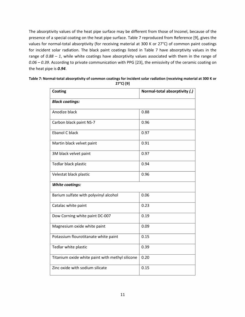
""!!
<3*!&\U0.S4('(4W!'&=1*U!0R!43*!3*&4!S(S*!U1.R&K*!V&W!\*!,(RR*.*)4!R.0V!430U*!0R!7)K0)*=5!\*K&1U*!0R!43*!S.*U*)K*!0R!&!US*K(&=!K0&4()2!0)!43*!3*&4!S(S*!U1.R&K*J!<&\=*!G!.*S.0,1K*,!R.0V!%*R*.*)K*!]:^5!2('*U!43*!'&=1*U!R0.!)0.V&=D404&=!&\U0.S4('(4W!?R0.!.*K*('()2!V&4*.(&=!&4!;$$![!0.!CGlTA!0R!K0VV0)!S&()4!K0&4()2U!R0.! ()K(,*)4! U0=&.! .&,(&4(0)J! <3*! \=&KM! S&()4! K0&4()2U! =(U4*,! ()! <&\=*! G! 3&'*! &\U0.S4('(4W! '&=1*U! ()! 43*!.&)2*!0R!1%33!4!/5!`3(=*!`3(4*!K0&4()2U!3&'*!&\U0.S4('(4W!'&=1*U!&UU0K(&4*,!`(43!43*V! ()! 43*!.&)2*!0R!1%15!4!1%-(J!YKK0.,()2!40!S.('&4*!K0VV1)(K&4(0)!`(43!NNa!]C;^5!43*!*V(UU('(4W!0R!43*!K*.&V(K!K0&4()2!0)!43*!3*&4!S(S*!(U!:;CBJ!
:%+;#'U0'N4",%;@.4.%;'%+)4"$.-S-./'4A'94,,4('94%.-(B)'A4"'-(9-&#(.')4;%"'"%&-%.-4('G"#9#-S-(B',%.#"-%;'%.'MQQ'7'4"'EUY8J'C[D'
84%.-(B' N4",%;@.4.%;'%+)4"$.-S-./'!;3'
D-'+0#+$')*E"1F#
Y)0,(i*!\=&KM! $JBB!
T&.\0)!\=&KM!S&()4!Z+DG! $J:@!
X\&)0=!T!\=&KM! $J:G!
6&.4()!\=&KM!'*='*4!S&()4! $J:"!
;6!\=&KM!'*='*4!S&()4! $J:G!
<*,=&.!\=&KM!S=&U4(K! $J:9!
b*=*U4&4!\=&KM!S=&U4(K! $J:@!
AG*).#+$')*E"1F#
L&.(1V!U1=R&4*!`(43!S0=W'()W=!&=K030=! $J$@!
T&4&=&K!`3(4*!S&()4! $JC;!
-0`!T0.)()2!`3(4*!S&()4!-TD$$G! $J":!
6&2)*U(1V!0F(,*!`3(4*!S&()4! $J$:!
N04&UU(1V!R=01.04(4&)&4*!`3(4*!S&()4! $J"#!
<*,=&.!`3(4*!S=&U4(K! $J;:!
<(4&)(1V!0F(,*!`3(4*!S&()4!`(43!V*43W=!U(=(K0)*! $JC$!
o()K!0F(,*!`(43!U0,(1V!U(=(K&4*! $J"#!
!

"C!!
4)B)'!;%?/.18'!;1+1.$%+/&$/.&'<3*!K3*V(K&=!U4.1K41.*!0R!U0,(1V!U1=R&4*!(U!2('*)!()!E(21.*!"J!!
!
T-B*"#'<0'85#,-9%;')."*9.*"#'4A'N%E?OP'C<QD'
+0,(1V! U1=R&4*! (U! 0,0.=*UU! &),! K3*V(K&==W! '*.W! U4&\=*5! \*()2! 1).*&K4('*! 40`&.,! V0U4! 0F(,(i()2! 0.!.*,1K()2!&2*)4U!&4!)0.V&=!4*VS*.&41.*UJ!Y4!3(23!4*VS*.&41.*U5!(4!K&)!\*!.*,1K*,!40!U0,(1V!U1=R(,*J!74!(U!&!)*14.&=!U&=45!`3(K3!R0.VU!&c1*01U!U0=14(0)U!`(43!S/!0R!GJ!<3*!)*14.&=(4W!0R!U1K3!U0=14(0)U!.*R=*K4U!43*!R&K4! 43&4! Z&C+Q9! (U! ,*.('*,5! R0.V&==W! US*&M()25! R.0V! 43*! U4.0)2! &K(,! U1=R1.(K! &K(,! &),! &! U4.0)2! \&U*!U0,(1V!3W,.0F(,*J!
+0,(1V!U1=R&4*!(U!&)!&=M&=(!U1=R&4*!R0.V*,!()!*F3&1U4!R=1*!2&U*U!0R!2=&UU!R1.)&K*U!,1*!40!U*'*.&=!?&4!=*&U4!R01.A!()4*.V*,(&4*!.*&K4(0)U!]#^!.*U1=4()2!()!43*!R0==0`()2!0'*.&==!K3*V(K&=!.*&K4(0)>!
CZYQ/!?2A!m!+QC!m!$J#QC! !Z&C+Q9!?2A!m!/CQ!
%*R*.*)K*! ]#^! 2('*U! &! 43*.V0,W)&V(K! K3&.&K4*.(i&4(0)! 0R! K0),*)U&4(0)! S.0,1K4U! R.0V! 2=&UU! R1.)&K*U5!`3(K3!U&WU!pU0=(,!0.! =(c1(,!&=M&=(!U1=R&4*U!&.*!43*!V&()!K0VS01),U!R0.V*,!,1.()2!43*!K00=()2!0R!&=M&=(D.(K3! &),! U1=R1.D.(K3! R=1*! 2&U*UqJ! <3*! K0),*)U&4(0)! (U! &=U0! 4301234! 40! \*! 0KK1..()2! ,1*! 40! 4`0!V*K3&)(UVU!8!R(.U4=W5!43*! ()K.*&U*,!U1S*.U&41.&4(0)!0R!U&=4!'&S0.U!&4!,*K.*&U*,!4*VS*.&41.*U! =*&,U!40!K0),*)U&4(0)! ()!43*!\1=M!R=1*!2&U5!&),!U*K0),=W5!K0),*)U&4(0)!`(==!0KK1.!,1*!40!S.*U*)K*!0R!.*=&4('*=W!K0=,!U1.R&K*U!()!43*!*F3&1U4!2&U!R=0`5!=*&,()2!40!43*!,*S0U(4(0)!0R!=(c1(,!0.!U0=(,!U&=4U!0)!43*U*!U1.R&K*UJ!%*R*.*)K*! ]#^! &=U0! U4&4*U! 43&4! p,*S0U(4(0)! 0R! &=M&=(! U1=R&4*U! (U! 0\U*.'*,! ()! .*2*)*.&40.U! &4! \.(KM!4*VS*.&41.*U! \*=0`! ";#$! [q5! `3(K3! (U! K0)U(U4*)4! `(43! 43*! 0\U*.'&4(0)U! R.0V! 43*! NNa! S=&)4J! <3*!V*K3&)(UV! 0R! R0.V&4(0)! 0)! 43*! 3*&4! S(S*! U1.R&K*U! K01=,! \*! \043! 43*! K0),*)U&4(0)! ,1*! 40!U1S*.U&41.&4(0)!0R!U&=4!'&S0.U!()!\1=M!R=1*!2&U5!&),!K0),*)U&4(0)!,1*!40!43*!=0`*.!4*VS*.&41.*!0R!43*!3*&4!S(S*!U1.R&K*J!
+0=1\(=(4W!&),!S3&U*!,&4&!R0.!,(RR*.*)4!&c1*01U!U0=14(0)U!K0)4&()()2!U0,(1V!U1=R&4*!&.*!2('*)!()!T3&S4*.!G!0R! %*R*.*)K*! ]"^J! Y! U0=1\(=(4W! S=04!0R!Z&C+Q9! ()!`&4*.! &4! '&.(01U! 4*VS*.&41.*U! R.0V!$lT! 40!C$$lT! (U!2('*)!()!E(21.*!C!?%*R*.*)K*U!]""^!&),!]#^AJ!74U!U0=1\(=(4W!.(U*U!V0.*!43&)!4*)R0=,!\*4`**)!$!lT!40!;CJ9!lT5!`3*.*!(4!.*&K3*U!&!V&F(V1V!0R!9:JG!2!Z&C+Q9!S*.!"$$!2!`&4*.J!Y4!43(U!S0()4!43*!U0=1\(=(4W!K1.'*!K3&)2*U!U=0S*!&),!43*!U0=1\(=(4W!\*K0V*U!&=V0U4!(),*S*),*)4!0R!4*VS*.&41.*J!

";!!
!
T-B*"#'E0'?4;*+-;-./'4A'N%E?OP'S)2':#,$#"%.*"#'C<<K'LD'

"9!!
B)'51+$/.-81$%'!12%'C"+?1$/"#'1#,'/$&'D::%.$'"#'E%1$'A+1#&:%+'<1$%&'!
-1.()2! 43*! K00=()2!0R! R=1*!2&U*U! U1K3!&U! 430U*! ()! 2=&UU! R1.)&K*U5! U0V*!0R! 43*! K0)U4(41*)4U!0R! 43*! R=1*!2&U*U!K0),*)U*!&),!R0.V!U0=(,!S&.4(K1=&4*!V&44*.J!%*U*&.K3! =(4*.&41.*! ]#^! (U!&'&(=&\=*!0)!43*!K3*V(K&=!K3&)2*U!0KK1..()2!,1.()2!43*!K00=()2!0R!*F3&1U4!2&U*U!()!&!2=&UU!R1.)&K*5!`3(K3!&=U0!2('*U!&!K&=K1=&4(0)!0R!43*!*c1(=(\.(1V!K0VS0U(4(0)!0R!43*!`&U4*!2&U!V(F41.*!R0.!4*VS*.&41.*U!R.0V!"$$$!40!"B$$![J!Y!4WS(K&=!`&U4*! 2&U! K0VS0U(4(0)! R.0V!&!2&UDR(.*,!2=&UU! R1.)&K*! (U! 2('*)! ()!<&\=*!TC! ()! YSS*),(F!TJ! <3(U! U*K4(0)!2('*U!&!\.(*R!,*UK.(S4(0)!0R!R0.V&4(0)!0R!S&.4(K1=&4*!V&44*.5!*US*K(&==W!0)!*F4*.)&=!U1.R&K*U!&),!(4U!*RR*K4!0)!3*&4!4.&)UR*.!.&4*J!
B)()'51+$/.-81$%'C"+?1$/"#'F%.;1#/&?&'L**.M*)U! *4! &=J! ];^! V*)4(0)! 43&4! pR01=()2! 0R! 3*&4! *FK3&)2()2! U1.R&K*U5! `3(K3! &.*! .*=&4('*=W! K0=,!K0VS&.*,!40!43*!R=1*!2&U*U5!(U!K&1U*,!\W!*(43*.>!
?&A!6&UU!4.&)UR*.!0R!2&U*01U!K0VS0)*)4U!R.0V!R=1*!2&U*U!40!K3&))*=!U1.R&K*U!&),!K0),*)U&4(0)!0R!43*U*!K0VS01),U!&4!43*!U1.R&K*U5!0.!
?\A!6&UU!4.&)US0.4!0R!,1U4!S&.4(K=*U!R.0V!43*!R=1*!2&U*U!40`&.,U!43*!3*&4!*FK3&)2()2!U1.R&K*UJq!
Y=U05! 43*! &'&(=&\=*! =(4*.&41.*! 0)! 43*! 40S(K! ];5! "C^! S0()4U! 014! 43&4! ()! U*K0),&.W! 3*&4! *FK3&)2*.U5! 43*!V*K3&)(UV!.*US0)U(\=*! R0.! R01=()2! (U!\AJ!Y4! 4*VS*.&41.*U!\*=0`!"$$$![5! 43*!S.0,1K4!0R! K0),*)U&4(0)!R.0V!R=1*!2&U*U!K0)U(U4U!V&()=W!0R!U1\DV(K.0V*4*.!S&.4(K=*UJ!<3*U*!S&.4(K=*U!&.*!,*S0U(4*,!0)!*F4*.)&=!U1.R&K*U!&),!0KK1.!V&()=W!,1*!40!0)*!0.!V0.*!0R!43*!V*K3&)(UVU!V*)4(0)*,!\*=0`!0KK1..()2!U*S&.&4*=W!0.!U(V1=4&)*01U=W>!
"J!a.&'(4&4(0)&=!U*44=()25!
CJ!-*S0U(4(0)!\W!()*.4(&!0R!43*!,1U4!S&.4(K=*U5!
;J!7)4*.K*S4(0)&=!,*S0U(4(0)!?0)=W!(VS0.4&)4!R0.!'*.W!.0123!U1.R&K*UA5!
9J!-*S0U(4(0)!\W!L.0`)(&)!,(RR1U(0)5!
#J!-*S0U(4(0)!\W!43*.V0S30.*4(K!R0.K*U!?(VS0.4&)4!R0.!UV&==!S&.4(K=*UAJ!
<3*.*!&.*!43.**!\&U(K!U4&2*U!0R!,*S0U(4(0)!0)!U1.R&K*U!R.0V!&!V0'()2!R=1(,!]";^>!
"J -(RR1U(0)&=!4.&)US0.4!0R!43*!S&.4(K1=&4*!V&44*.!43&4!R0.VU!43*!,*S0U(4!?0.!(4U!S.*K1.U0.UA!&K.0UU!43*!\01),&.W!=&W*.U!&,O&K*)4!40!43*!U0=(,!U1.R&K*!`(43()!43*!R=0`()2!R=1(,5!
CJ Y,3*U(0)!0R!43*!,*S0U(4!40!43*!U1.R&K*!&),!40!(4U*=R5!&),!
;J <.&)US0.4!0R!43*!,*S0U(4!V&4*.(&=!&`&W!R.0V!43*!U0=(,!U1.R&K*J!
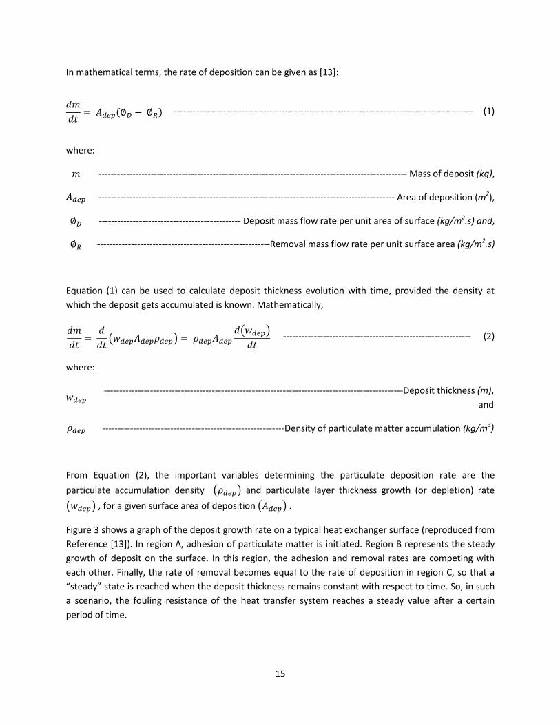
"#!!
7)!V&43*V&4(K&=!4*.VU5!43*!.&4*!0R!,*S0U(4(0)!K&)!\*!2('*)!&U!]";^>!
QRQS T UVWXYZ[ \ Z]^! DDDDDDDDDDDDDDDDDDDDDDDDDDDDDDDDDDDDDDDDDDDDDDDDDDDDDDDDDDDDDDDDDDDDDDDDDDDDDDDDDDDDDDDDDDDDDDDDD! ?"A!
`3*.*>!R! DDDDDDDDDDDDDDDDDDDDDDDDDDDDDDDDDDDDDDDDDDDDDDDDDDDDDDDDDDDDDDDDDDDDDDDDDDDDDDDDDDDDDDDDDDDDDDDDDDDD!6&UU!0R!,*S0U(4!.6725!UVWX! DDDDDDDDDDDDDDDDDDDDDDDDDDDDDDDDDDDDDDDDDDDDDDDDDDDDDDDDDDDDDDDDDDDDDDDDDDDDDDDDDDDDDDDDDDDDDDDD!Y.*&!0R!,*S0U(4(0)!?$'A5!Z[! DDDDDDDDDDDDDDDDDDDDDDDDDDDDDDDDDDDDDDDDDDDDDD!-*S0U(4!V&UU!R=0`!.&4*!S*.!1)(4!&.*&!0R!U1.R&K*!.67#$'%82!9:;5!Z]! DDDDDDDDDDDDDDDDDDDDDDDDDDDDDDDDDDDDDDDDDDDDDDDDDDDDDDDD%*V0'&=!V&UU!R=0`!.&4*!S*.!1)(4!U1.R&K*!&.*&!.67#$'%82!
!
Xc1&4(0)! ?"A! K&)! \*! 1U*,! 40! K&=K1=&4*! ,*S0U(4! 43(KM)*UU! *'0=14(0)!`(43! 4(V*5! S.0'(,*,! 43*! ,*)U(4W! &4!`3(K3!43*!,*S0U(4!2*4U!&KK1V1=&4*,!(U!M)0`)J!6&43*V&4(K&==W5!!QRQS T QQS _`VWXUVWXaVWXb T aVWXUVWX Q_`VWXbQS ! DDDDDDDDDDDDDDDDDDDDDDDDDDDDDDDDDDDDDDDDDDDDDDDDDDDDDDDDDDDDD! ?CA!
`3*.*>!
`VWX! DDDDDDDDDDDDDDDDDDDDDDDDDDDDDDDDDDDDDDDDDDDDDDDDDDDDDDDDDDDDDDDDDDDDDDDDDDDDDDDDDDDDDDDDDDDDDDDDD-*S0U(4!43(KM)*UU!.$25!&),!aVWX! DDDDDDDDDDDDDDDDDDDDDDDDDDDDDDDDDDDDDDDDDDDDDDDDDDDDDDDDDDD-*)U(4W!0R!S&.4(K1=&4*!V&44*.!&KK1V1=&4(0)!.67#$-2!
!
E.0V! Xc1&4(0)! ?CA5! 43*! (VS0.4&)4! '&.(&\=*U! ,*4*.V()()2! 43*! S&.4(K1=&4*! ,*S0U(4(0)! .&4*! &.*! 43*!
S&.4(K1=&4*! &KK1V1=&4(0)! ,*)U(4W! ! _aVWXb! &),! S&.4(K1=&4*! =&W*.! 43(KM)*UU! 2.0`43! ?0.! ,*S=*4(0)A! .&4*!_`VWXb!5!R0.!&!2('*)!U1.R&K*!&.*&!0R!,*S0U(4(0)!_UVWXb!J!E(21.*!;!U30`U!&!2.&S3!0R!43*!,*S0U(4!2.0`43!.&4*!0)!&!4WS(K&=!3*&4!*FK3&)2*.!U1.R&K*!?.*S.0,1K*,!R.0V!%*R*.*)K*!]";^AJ!7)!.*2(0)!Y5!&,3*U(0)!0R!S&.4(K1=&4*!V&44*.!(U!()(4(&4*,J!%*2(0)!L!.*S.*U*)4U!43*!U4*&,W!2.0`43!0R!,*S0U(4!0)! 43*!U1.R&K*J! 7)! 43(U! .*2(0)5! 43*!&,3*U(0)!&),! .*V0'&=! .&4*U! &.*! K0VS*4()2!`(43!*&K3!043*.J!E()&==W5!43*!.&4*!0R!.*V0'&=!\*K0V*U!*c1&=!40!43*!.&4*!0R!,*S0U(4(0)! ()!.*2(0)!T5!U0!43&4!&!pU4*&,Wq!U4&4*!(U!.*&K3*,!`3*)!43*!,*S0U(4!43(KM)*UU!.*V&()U!K0)U4&)4!`(43!.*US*K4!40!4(V*J!+05!()!U1K3!&! UK*)&.(05! 43*! R01=()2! .*U(U4&)K*! 0R! 43*! 3*&4! 4.&)UR*.! UWU4*V! .*&K3*U! &! U4*&,W! '&=1*! &R4*.! &! K*.4&()!S*.(0,!0R!4(V*J!

"@!!
!
T-B*"#'M0'W&#%;-\#&'"#$"#)#(.%.-4('4A'95%(B#'-('&#$4)-.'.5-9](#))'H-.5'.-,#'C<MD'
7R!43*!S&.4(K1=&4*!.*V0'&=!V&UU!R=0`!.&4*!?R0.!&!US*K(R(K!K&U*A!K&)!\*!K0)U(,*.*,!)*2=(2(\=*5!Xc1&4(0)!?"A!\*K0V*U>!QRQS T Z[! DDDDDDDDDDDDDDDDDDDDDDDDDDDDDDDDDDDDDDDDDDDDDDDDDDDDDDDDDDDDDDDDDDDDDDDDDDDDDDDDDDDDDDDDDDDDDDDDDDDDDDDDDDDDDDDDD! ?;A!
!
7)!K&U*!43(U!&UU1VS4(0)!(U!'&=(,5!43*!.&4*!0R!K3&)2*!0R!,*S0U(4!43(KM)*UU!`(==!&=`&WU!\*!)0)D)*2&4('*5!&),!3*)K*!43*!R01=()2!.*U(U4&)K*!D!cd!D!?`3(K3!,*S*),U!0)!43*!,*S0U(4!43(KM)*UUA!0R!43*!*)4(.*!3*&4!4.&)UR*.!UWU4*V!M**SU!()K.*&U()2!0.!.*V&()U!U4*&,W!`(43!4(V*J!
B)4)'C"-8/#3'1#,'/$&'D::%.$&'"#'E%1$'A+1#&:%+'<1$%&'YU!43*!S&.4(K1=&4*!,*S0U(4(0)!.&4*!K3&)2*U!`(43!4(V*!,(RR*.*)4=W!()!'&.(01U!3*&4!*FK3&)2*.U5!43*!R01=()2!.*U(U4&)K*! cd! &=U0! ()K.*&U*U! ()! ,(RR*.*)4! `&WUJ! %*R*.*)K*! ]"9^! U30`U! *F&VS=*U! 0R! =()*&.5! R&==()25!
&UWVS404(K! &),! U&`D40043! .&4*U! 0R! K3&)2*! ()! R01=()2! .*U(U4&)K*! ()! ,(RR*.*)4! 3*&4! *FK3&)2*.U5! &),! (U!c1&=(4&4('*=W!,*S(K4*,!()!E(21.*!9J!

"G!!
!
T-B*"#'P0'!4))-+;#'A4*;-(B'"#)-).%(9#'S#")*)'.-,#'9*"S#)'C<PD'
N&.4(K1=&4*! K0)4.0=!3&U!\**)!1U*,! ()! (),1U4.(*U!1U()2!3*&4!*FK3&)2*.U! R0.!,*K&,*U5! R0.! .*'('&=!0R!3*&4!*FK3&)2*.! *RR*K4('*)*UUJ! N*.(0,(K! K=*&)()2! 0R! 3*&4! *FK3&)2*.U! (U! )*K*UU&.W5! *'*)! R0.! &!`*==D,*U(2)*,!3*&4!*FK3&)2*.5!U()K*!43*!,*S0U(4(0)!0R!S&.4(K1=&4*!V&44*.!(U!&!K3&.&K4*.(U4(K!0R!43*!UWU4*V5!&),!,*S*),U!0)!43*!V*,(1V!0R!K00=()2!&),!43*!K3*V(K&=!K0VS0U(4(0)!0R!43*!S&.4(K=*UJ!
Z0`5! U()K*! `*! &.*! ()4*.*U4*,! ()! R(),()2! 014! 43*! *RR*K4! 0R! S&.4(K1=&4*! ,*S0U(4(0)! 0)! 3*&4! 4.&)UR*.!S*.R0.V&)K*!0R!43*!3*&4!S(S*5!`*!)**,!40!4&M*!&!K=0U*.!=00M!&4!43*!*)*.2W!\&=&)K*!0R!43*!3*&4!S(S*!&4!U4*&,W!U4&4*J!E(21.*!#!U30`U!&!UK3*V&4(K!0R!43*!U&V*J!
!T-B*"#'L0'=(#"B/'+%;%(9#')95#,%.-9'4A'.5#'5#%.'$-$#'%.'^).#%&/^').%.#'

"B!!
+()K*!43*!K0)4.0=!'0=1V*!(U!K30U*)!U1K3!43&4!43*!V&UU!R=0`U!()!&),d0.!014!0R!43*!UWU4*V!&.*!43*!V&UU!R=0`!0R! K00=()2!`&4*.! ()40! &),! 014! 0R! 43*! K00=()2!`&4*.! O&KM*4! 0)! 43*! 014*.! U1.R&K*! 0R! 43*! <Xa5! 43(U!\*K0V*U!&)!0S*)!UWU4*V!S.0\=*VJ!<3*!*)*.2W!\&=&)K*!0R!43(U!0S*)!UWU4*V!*FS.*UU*,!V&43*V&4(K&==W!(U>!
efgh T if \ jf k Rf lmn_opqr \ opsthb! DDDDDDDDDDDDDDDDDDDDDDDDDDDDDDDDDDDDDDDDDDDDDDDDDDDDDDDDDDDDDDDDDDDDDDDDDDDDDDD! ?9&A!
`3*.*>!efgh ! DDDDDDDDDDDDDDDDDDDDDDDDDDDDDDDDDDDDDDDDDDDDDDDDDDDD!%&4*!0R!K3&)2*!0R!*)*.2W!U40.*,!()!43*!UWU4*V!."25!if ! DDDDDDDDDDDDDDDDDDDDDDDDDDDDDDDDDDDDDDDDDDDDDDD!Z*4!.&4*!0R!3*&4!4.&)UR*.!()40!0.!014!0R!43*!UWU4*V!."2<!jf ! DDDDDDDDDDDDDDDDDDDDDDDDDDDDDDDDDDDDDDDDDDDDDDDDDDDDDDDDDD!Z*4!.&4*!0R!`0.M!()40!0.!014!0R!43*!UWU4*V!."2<!Rf lmn! DDDDDDDDDDDDDDDDDDDDDDDDDDDDDDDDDDDDDDDDDDDDDDDDDDDDDDDDDDDDDDDDDDDDDDDDD!6&UU!R=0`!.&4*!0R!`&4*.!?M2dUA5!&),!
opqr \ opsth! D!-(RR*.*)K*!()!US*K(R(K!*)43&=SW!0R!`&4*.!*)4*.()2!?f()gA!&),!=*&'()2!?f014gA!43*!UWU4*V!.=#672!
/*.*5!(4!U301=,!\*!)04*,!43&4!&KK0.,()2!40!43*!K0)'*)4(0)!1U*,!R0.!*)*.2W!\&=&)K*!0R!0S*)!UWU4*VU!&4!U4*&,W!U4&4*!R.0V!%*R*.*)K*U!]"#5!@^5!3*&4!4.&)UR*.! ()40!43*!UWU4*V!(U!K0)U(,*.*,!fmg!&),!3*&4!4.&)UR*.!014!0R! 43*! UWU4*V! (U! K0)U(,*.*,! fDgJ! Y=U05!`0.M! 014S14! \W! 43*! UWU4*V! (U! K0)U(,*.*,! fmg5!`3*.*&U!`0.M!()S14!40!43*!UWU4*V!(U!K0)U(,*.*,!&U!fDgJ!
E0.!&!K0)U4&)4!US*K(R(K!3*&4!0R!`&4*.5!43*!*)43&=SW!,(RR*.*)K*!4*.V!()!Xc1&4(0)!?9&A!K&)!\*!`.(44*)!&U>!
Rf lmn_opqr \ opsthb T \Rf lmnuX,lmn_vsth,lmn \ vqr,lmnb! DDDDDDDDDDDDDDDDDDDDDDDDDDDDDDDDDDDDDDDDDDDDDDDDDDD! ?9\A!
E0.!43*!UWU4*V!43&4!(U!K0)U(,*.*,!()!E(21.*!#5!&4!U4*&,W!U4&4*5!`*!M)0`!43&4!43*!()4*.)&=!*)*.2W!0R!43*!UWU4*V!(U!K0)U4&)45!U()K*!`3*)!43*!R=1(,!?=(c1(,!U0,(1VA!K0VS=*4*U!0)*!KWK=*!43.0123!43*!3*&4!S(S*5! (4!
.*41.)U!40!43*!U&V*!U4&4*!R0.!&!2('*)!=0K&4(0)!0R!43*!3*&4!S(S*!?!&),!3*)K*5!efgh T 0!AJ!Z0`5!Xc1&4(0)!?9A!K&)!\*!V0,(R(*,5!M)0`()2!43&4>!
"J /*&4!4.&)UR*.!()40!43*!UWU4*V!0KK1.U!'(&!.&,(&4(0)5!
CJ /*&4!4.&)UR*.!\W!K0)'*K4(0)!4&M*U!S=&K*!014!0R!43*!3*&4!S(S*!&),!()40!43*!R=1*!2&U!U()K*!43*!3*&4!S(S*!014*.!U1.R&K*!(U!&4!&!4*VS*.&41.*!2.*&4*.!43&)!43*!2&U!4*VS*.&41.*5!
;J /*&4!=0UU!R.0V!43*!<Xa!40!&V\(*)4!?43.0123!)&41.&=!K0)'*K4(0)!0)!43*!014*.!U1.R&K*U!0R!43*!<Xa!&),!3*&4!S(S*!*),A!&.*!4&M()2!S=&K*5!&=0)2!`(43!3*&4!4.&)UR*.!()4*.)&=!40!43*!UWU4*V!()!E(21.*!#!
`3(K3! K&1U*U! US*K(R(K! *)43&=SW! 0R! `&4*.! *F(4()2! 43*! UWU4*V! _opsthb! 40! \*! 3(23*.! 43&)! 43&4! 0R!`&4*.!*)4*.()2!43*!UWU4*V!_opqrb5!
9J P0.M!014S14!R.0V!43*!UWU4*V!(U!43*!*=*K4.(K&=!S0`*.!43&4!(U!0\4&()*,!R.0V!43*!<Xa!V0,1=*5!&),!

":!!
#J Y4! U4*&,W! U4&4*5! 43*! .&4*! 0R! *)*.2W! U40.&2*! ?0.! &KK1V1=&4(0)A! 0R! 43*! UWU4*V! (U! i*.0J! 7)! 043*.!`0.,U5!43*!404&=!*)*.2W!0R!43*!UWU4*V!(U!K0)U4&)4!&4!&!U4&4*!0R!*c1(=(\.(1VJ!
+05!R.0V!Xc1&4(0)!?9A5!
efgh T ifwxV \ ifysrz \ if {sgg \ jf sth \ Rf lmnuX,lmn_vsth,lmn \ vqr,lmnb T 0! DDDDDDDDDDDD! ?#&A!
E.0V!Xc1&4(0)!?#&A5!43*!S0`*.!014S14!R.0V!43*!UWU4*V!V&W!\*!K&=K1=&4*,!&U>!
jf sth T ifwxV \ ifysrz \ if {sgg \ Rf lmnuX,lmn_vsth,lmn \ vqr,lmnb! DDDDDDDDDDDDDDDDDDDDDDDDDDDDDDDD! ?#\A!
7)!0.,*.!40!K&=K1=&4*!jf sth!R0.!43*!UWU4*V!?43*!*)4(.*!3*&4!S(S*!&),!<Xa!()K=1,()2!43*!`&4*.!O&KM*4A5!43*!R0==0`()2!)**,!40!\*!K&=K1=&4*,>!
"J ifwxV!5!CJ ifysrz!5!&),!;J if {sgg!J!
Y=U05!Rf lmn!5!vsth,lmn!&),!vqr,lmn!)**,!40!\*!M)0`)!R0.!K&=K1=&4()2!43*!%/+!0R!Xc1&4(0)!?#\AJ!E(.U45!`*!=00M!&4!30`!40!*U4(V&4*!ifwxVJ!E0.!,*.('()2!43*!.&,(&4(0)!3*&4!4.&)UR*.!.&4*5!43*!2*0V*4.W!0R!43*!UWU4*V!0R!4`0!\0,(*U!8!*V(44()2!&),!&\U0.\()2!D!(U!&UU1V*,!40!\*!U(VS=(R(*,!&U!U30`)!()!E(21.*!@J!
/*.*5!43*!1SS*.!U1.R&K*!0R!43*!3*&4!S(S*!(U!&SS.0F(V&4*,!40!\*!&!R=&4!U1.R&K*!0R!&.*&!*c1&=!40!43*!U1V!0R!43*!1SS*.!K1.'*,!U1.R&K*!&.*&!0R!43*!S(S*!3&'()2!&)!014*.!,(&V*4*.!0R!;J#!()K3*U!&),!:J;!R**4!=0)25!&),!R=&4! U1.R&K*! &.*&!0R! 4`0! R()U! ;! ()K3*U!`(,*! &),! :J;! R**4! =0)2J! <3*! &UU1V*,! '&=1*U! 0R! 43*! ,(V*)U(0)U!,*S(K4*,!()!E(21.*!@!1U*,!R0.!43*!K&=K1=&4(0)U!()!YSS*),(F!-!&.*>!`q T 3.3 |S.5! }̀ T 9.5 ~�.5!� T 16.7 |S.5!&),!!�q T �} T 9.3 |S.!<3*!.&4*!&4!`3(K3!404&=! .&,(&4(0)!0R! 43*!*V(44()2!U1.R&K*! ?()! 43(U!K&U*5! 43*! R1.)&K*A! (U!&\U0.\*,!\W!43*!3*&4!&\U0.\()2!U1.R&K*!?1SS*.!3&=R!0R!3*&4!S(S*A!&UU1V()2!43*!R1.)&K*!&U!&!\=&KM\0,W!K&)!\*!K&=K1=&4*,!&U>!
ifwxV T Ug�dg��g_vd� \ vg�b! DDDDDDDDDDDDDDDDDDDDDDDDDDDDDDDDDDDDDDDDDDDDDDDDDDDDDDDDDDDDDDDDDDDDDDDDDDDDDDD! ?@A!
`3*.*>!
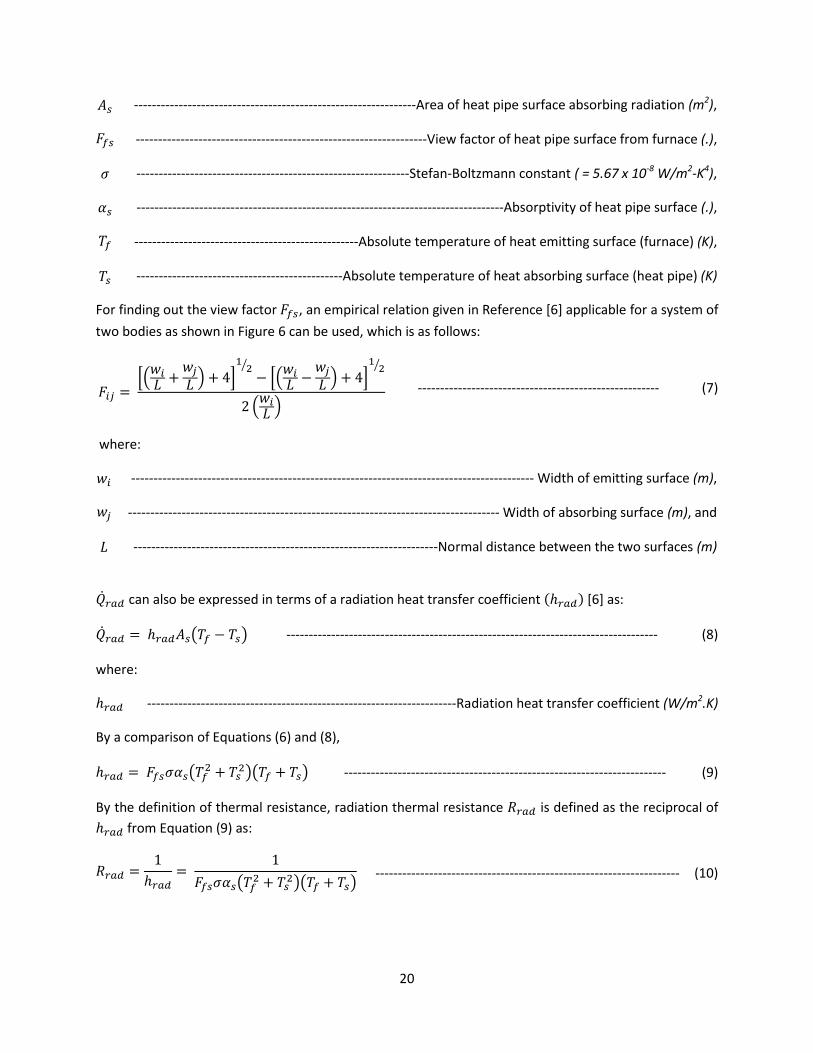
C$!!
Ug! DDDDDDDDDDDDDDDDDDDDDDDDDDDDDDDDDDDDDDDDDDDDDDDDDDDDDDDDDDDDDDDY.*&!0R!3*&4!S(S*!U1.R&K*!&\U0.\()2!.&,(&4(0)!.$'25!�dg! DDDDDDDDDDDDDDDDDDDDDDDDDDDDDDDDDDDDDDDDDDDDDDDDDDDDDDDDDDDDDDDDDb(*`!R&K40.!0R!3*&4!S(S*!U1.R&K*!R.0V!R1.)&K*!.%25!�! DDDDDDDDDDDDDDDDDDDDDDDDDDDDDDDDDDDDDDDDDDDDDDDDDDDDDDDDDDDDD+4*R&)DL0=4iV&))!K0)U4&)4!.!>!)%50!?!/1@3!"#$'@&,25!�g! DDDDDDDDDDDDDDDDDDDDDDDDDDDDDDDDDDDDDDDDDDDDDDDDDDDDDDDDDDDDDDDDDDDDDDDDDDDDDDDDDDY\U0.S4('(4W!0R!3*&4!S(S*!U1.R&K*!.%25!vd! DDDDDDDDDDDDDDDDDDDDDDDDDDDDDDDDDDDDDDDDDDDDDDDDDDY\U0=14*!4*VS*.&41.*!0R!3*&4!*V(44()2!U1.R&K*!?R1.)&K*A!.&25!vg! DDDDDDDDDDDDDDDDDDDDDDDDDDDDDDDDDDDDDDDDDDDDDDY\U0=14*!4*VS*.&41.*!0R!3*&4!&\U0.\()2!U1.R&K*!?3*&4!S(S*A!.&2!
E0.!R(),()2!014!43*!'(*`!R&K40.!�dg5!&)!*VS(.(K&=!.*=&4(0)!2('*)!()!%*R*.*)K*!]@^!&SS=(K&\=*!R0.!&!UWU4*V!0R!
4`0!\0,(*U!&U!U30`)!()!E(21.*!@!K&)!\*!1U*,5!`3(K3!(U!&U!R0==0`U>!
�q} T ��`q� k }̀� � k 4�� �� \ ��`q� \ }̀� � k 4�� ��2 �`q� � ! DDDDDDDDDDDDDDDDDDDDDDDDDDDDDDDDDDDDDDDDDDDDDDDDDDDDDD! ?GA!
!`3*.*>!`q! DDDDDDDDDDDDDDDDDDDDDDDDDDDDDDDDDDDDDDDDDDDDDDDDDDDDDDDDDDDDDDDDDDDDDDDDDDDDDDDDDDDDDDDDDD!P(,43!0R!*V(44()2!U1.R&K*!.$25!
}̀! DDDDDDDDDDDDDDDDDDDDDDDDDDDDDDDDDDDDDDDDDDDDDDDDDDDDDDDDDDDDDDDDDDDDDDDDDDDDDDDDDDD!P(,43!0R!&\U0.\()2!U1.R&K*!.$25!&),!�! DDDDDDDDDDDDDDDDDDDDDDDDDDDDDDDDDDDDDDDDDDDDDDDDDDDDDDDDDDDDDDDDDDDDZ0.V&=!,(U4&)K*!\*4`**)!43*!4`0!U1.R&K*U!.$2!
!ifwxV!K&)!&=U0!\*!*FS.*UU*,!()!4*.VU!0R!&!.&,(&4(0)!3*&4!4.&)UR*.!K0*RR(K(*)4!YowxV^!]@^!&U>!ifwxV T owxVUg_vd \ vgb! DDDDDDDDDDDDDDDDDDDDDDDDDDDDDDDDDDDDDDDDDDDDDDDDDDDDDDDDDDDDDDDDDDDDDDDDDDDDDDDDDDD! ?BA!
`3*.*>!owxV! DDDDDDDDDDDDDDDDDDDDDDDDDDDDDDDDDDDDDDDDDDDDDDDDDDDDDDDDDDDDDDDDDDDDD%&,(&4(0)!3*&4!4.&)UR*.!K0*RR(K(*)4!."#$'%&2!
LW!&!K0VS&.(U0)!0R!Xc1&4(0)U!?@A!&),!?BA5!owxV T �dg��g_vd� k vg�b_vd k vgb! DDDDDDDDDDDDDDDDDDDDDDDDDDDDDDDDDDDDDDDDDDDDDDDDDDDDDDDDDDDDDDDDDDDDDDDD! ?:A!
LW!43*!,*R()(4(0)!0R!43*.V&=!.*U(U4&)K*5!.&,(&4(0)!43*.V&=!.*U(U4&)K*!cwxV!(U!,*R()*,!&U!43*!.*K(S.0K&=!0R!owxV!R.0V!Xc1&4(0)!?:A!&U>!
cwxV T 1owxV T 1�dg��g_vd� k vg�b_vd k vgb! DDDDDDDDDDDDDDDDDDDDDDDDDDDDDDDDDDDDDDDDDDDDDDDDDDDDDDDDDDDDDDDDDDDD! ?"$A!
! !

!
T-B*"#'V0'>')95#,%.-9'"#$"#)#(.%.-4(
!
! !
C"!
'4A'.5#'A*"(%9#'%(&'5#%.'$-$#')*"A%9#)'A4"'"%&-%.-4('5#%.'.9%;9*;%.-4()'
!."%()A#"'

CC!!
E0.K*,!K0)'*K4(0)!3*&4!4.&)UR*.!.&4*!40!&!R=1(,!?*F3&1U4!R=1*A!R.0V!&!KW=(),.(K&=!*F4*.)&=!U1.R&K*!()!K.0UUDR=0`!(U!2('*)!&U!]@^>!
ifysrz T o�Ug_vg \ v�b! DDDDDDDDDDDDDDDDDDDDDDDDDDDDDDDDDDDDDDDDDDDDDDDDDDDDDDDDDDDDDDDDDDDDDDDDDDDDDDDDDDDDDDDDDDDDDDD! ?""A!
`3*.*>!o�! DDDDDDDDDDDDDDDDDDDDDDDDDDDDDDDDDDDDDDDDDDDDDDDDDDDDDDDDDDY'*.&2*!K0)'*K4('*!3*&4!4.&)UR*.!K0*RR(K(*)4!."#$'%&25!Ug! DDDDDDDDDDDDDDDDDDDDDDDDDDDDDDDDDDDDDDDDDDDDDDDDDDDDDDDDDDDDDDDDDDDDDDDDDDDDDD<04&=!U1.R&K*!&.*&!0R!3*&4!4.&)UR*.!.$'25!vg! DDDDDDDDDDDDDDDDDDDDDDDDDDDDDDDDDDDDDDDDDDDDDDDDDDDDDDDDDDDY\U0=14*!4*VS*.&41.*!0R!3*&4!4.&)UR*.!U1.R&K*!.&25!&),!v�! DDDDDDDDDDDDDDDDDDDDDDDDDDDDDDDDDDDDDDDDDDDDDDDDDDDDDDDDDDDDDDDDY\U0=14*!\1=M!4*VS*.&41.*!0R!*F3&1U4!2&U!.&2J!
Z04*! 43&4! ()! Xc1&4(0)! ?@A5! ,*S*),()2! 0)! 43*! U(2)! 0R! 43*! 4*.V! 0)! 43*! .(234D3&),! U(,*5!ifysrz! K&)! \*!S0U(4('*!0.!)*2&4('*5!K0..*US0),()2!40!3*&4!\*()2!U1SS=(*,!40!43*!S&.4!0R!43*!UWU4*V!()!43*!R=1*!,1K4!?(R!_v� � vgbA!0.!3*&4!\*()2!.*V0'*,!!R.0V!43*!UWU4*V!?(R!_v� � vgbA!.*US*K4('*=WJ!7)!0.,*.!40!K&=K1=&4*!43*!&'*.&2*!K0)'*K4('*!3*&4!4.&)UR*.!K0*RR(K(*)45!K*.4&()!K0..*=&4(0)U!&.*!K0VV0)=W!1U*,! &KK0.,()2! 40! %*R*.*)K*! ]@^5! 0)*! 0R! `3(K3! (U! 43*! o31M&1UM&U! K0..*=&4(0)! ?1U*,! R0.! &! KW=(),.(K&=!U1.R&K*!()!K.0UUDR=0`AJ!<3*!Z1UU*=4!)1V\*.!\&U*,!0)!43*!,(&V*4*.!(U!&U!R0==0`U>!
������[ T o��� T �c�[���r � ����g�� ��! DDDDDDDDDDDDDDDDDDDDDDDDDDDDDDDDDDDDDDDDDDDDDDDDDDDDDDDDDDDDDDDDDDDDDDDDDDDDDDD! ?"CA!
R0.! ! !0.7 � �� � 500! ! !
&),! ! !1 � c�[ � 10�! ! !
`3*.*>!c�[! DDDDDDDDDDDDDDDDDDDDDDDDDDDDDDDDDDDDDDDDDDDDDDD%*W)0=,gU!)1V\*.!\&U*,!0)!,(&V*4*.!0R!KW=(),.(K&=!U1.R&K*!?JA5!��! DDDDDDDDDDDDDDDDDDDDDDDDDDDDDDDDDDDDDDDDDDDDDDDDDDDDDDDDDDDDDDDDDDDDDDDDDDDDDDDN.&),4=!)1V\*.!0R!43*!*F3&1U4!2&U!?JA5!��g! DDDDDDDDDDDDDDDDDDDDDDDDDDDDN.&),4=!)1V\*.!0R!43*!*F3&1U4!2&U!K&=K1=&4*,!&4!43*!U1.R&K*!4*VS*.&41.*!?JA5!�! DDDDDDDDDDDDDDDDDDDDDDDDDDDDDDDDDDDDDDDDDDDDDDDDDDDDDDDDDDDDDDDDDDDDDDDDDDDD-(&V*4*.!0R!KW=(),.(K&=!U1.R&K*!.$25!&),!�! DDDDDDDDDDDDDDDDDDDDDDDDDDDDDDDDDDDDDDDDDDDDDDDDDDDDDDDDDDDDDDDDDDDD<3*.V&=!K0),1K4('(4W!0R!*F3&1U4!2&U!."#$@&2!

C;!!
7)!Xc1&4(0)!?GA5!43*!S.*D,*4*.V()*,!K0)U4&)4U!�!&),!R!&.*!2('*)! ()!%*R*.*)K*!]@^!&U!R1)K4(0)U!0R!c�[!&),!43*!K0)U4&)4!�!(U!2('*)!&U!&!R1)K4(0)!0R!��5!&U!2('*)!()!<&\=*!B!\*=0`J!
:%+;#'_0'84().%(.)'�K'�'%(&' '-('=`*%.-4('GUJ'A4"'9/;-(&#"'-('9"4))@A;4H'CVD'¡O¢' �' �'
"D9$! $JG#! $J9!
9$D"$$$! $J#"! $J#!
"$$$DC!F!"$#! $JC@! $J@!
C!F!"$#!8!"!F!"$@! $J$G@! $JG!
! ! !£¤' ' '
r!"$! $J;G! !
s!"$! $J;@! !
E.0V!Xc1&4(0)!?"CA5!(4!R0==0`U!43&4>!
o� T ������[ ��! DDDDDDDDDDDDDDDDDDDDDDDDDDDDDDDDDDDDDDDDDDDDDDDDDDDDDDDDDDDDDDDDDDDDDDDDDDDDDDDDDDDDDDDDDDDDDDDDD! ?";A!
!
/*)K*5!o�!K&)!\*!K&=K1=&4*,!R0.!43*!2('*)!K0),(4(0)U!0R!43*!*F3&1U4!2&U!R=0`!&),!&SS=(*,!\&KM!40!Xc1&4(0)!?@A5! R.0V!`3(K3!43*!K0)'*K4('*!3*&4! 4.&)UR*.! .&4*!K&)!\*!K&=K1=&4*,5!M)0`()2!43*!404&=!U1.R&K*!&.*&!0R!3*&4! 4.&)UR*.! &),! 43*! 2&U*01U! &),! U1.R&K*! 4*VS*.&41.*UJ! Y! U&VS=*! K&=K1=&4(0)! ,*V0)U4.&4()2!
K&=K1=&4(0)!0R!o�!R0.!&!V*&)!2&U!4*VS*.&41.*!v� T 600¥!R0.!'&.(01U!U1.R&K*!4*VS*.&41.*U!vg!(U!U30`)!()!YSS*),(F!-J!
<3*!)*F4!c1&)4(4W!43&4!(U!0R!()4*.*U4!40!K&=K1=&4*!R0.!U0='()2!Xc1&4(0)!?#\A!(U!if{sggJ!<3(U!(U!43*!&,,(4(0)&=!3*&4!=0UU!R.0V!43*!<Xa!40!43*!&V\(*)45!&),!(U!&UU1V*,!40!\*!0KK1..()2!*)4(.*=W!,1*!40!R.**!K0)'*K4(0)!0)! 43*!*F4*.)&=! U1.R&K*U!0R! 43*!<Xa! ?&=430123! .&,(&4(0)!3*&4! 4.&)UR*.!V&W!&=U0!\*!0KK1..()2! R.0V!43*!<Xa!*F4*.)&=!U1.R&K*U!40!43*!&V\(*)4AJ!Xc1&4(0)!?"9A!2('*U!43*!c1&)4(4&4('*!*FS.*UU(0)!R0.!43*!U&V*J!7R!43*!*F4*.)&=!U1.R&K*U!0R!43*!<Xa!K&)!\*!&SS.0F(V&4*,!40!\*!K0)U(U4()2!0R!&!US3*.*!0R!43*!U&V*!,(&V*4*.!&U!43*!&'*.&2*!,(V*)U(0)!0R!43*!<Xa!U*41S5!Xc1&4(0)!?"#A!2('*U!43*!&'*.&2*!Z1UU*=4!)1V\*.!\&U*,!0)!43*! ,(&V*4*.! 0R! &)! (U043*.V&=! US3*.(K&=! U1.R&K*! *FS0U*,! 40! )&41.&=! K0)'*K4(0)! ]@^5! R.0V! `3(K3! 43*!
&'*.&2*!K0)'*K4(0)!3*&4!4.&)UR*.!K0*RR(K(*)4!_o�¦b!K&)!\*!K&=K1=&4*,J!if{sgg T o�¦Uqrh_v�,s \ vx�§b! ! ?"9A!

C9!!
`3*.*>! ! !
������[ T o�¦�qrh�¨x T©ªª«ªª¬0.60k 0.387c[_� �� b
®1 k �0.559�� ��̄�° ±�²³ªª́ªªµ�
! ! ?"#A!
R0.!!c[ ¶ 10��! ! !
`3*.*>!�qrh! DDDDDDDDDDDDDDDDDDDDDDDDDDDDDDDDDDDDDDDDDDDDDDDDDDDDDDDDDDDDDDDDDDDDDDDDDD!7)4*.)&=!,(&V*4*.!0R!43*!3*&4!S(S*!.$25!�¨x! DDDDDDDDDDDDDDDDDDDDDDDDDDDDDDDDDDDDDDDDDDDDDDDDDDDDDDDDDDDDDDD!<3*.V&=!K0),1K4('(4W!0R!=(c1(,!U0,(1V!."#$%&25!Uqrh! DDDDDDDDDDDDDDDDDDDDDDDDDDDDDDDDDDDDDDDDDDDDDDDDDDDDDDDDDDD!7)4*.)&=!K1.'*,!U1.R&K*!&.*&!0R!43*!3*&4!S(S*!.$'25!v�,s! DDDDDDDDDDDDDDDDDDDDDDDDDDDDDDDDDDDDDDDDDDDDDDDDDDDDDDDDD!/*&4!S(S*!014*.!V*4&=!U1.R&K*!4*VS*.&41.*!.&25!&),!vx�§! DDDDDDDDDDDDDDDDDDDDDDDDDDDDDDDDDDDDDDDDDDDDDDDDDDDDDDDDDDDDDDDDDDDDDDDDDDDDDDDDDDDDDDDDDDD!YV\(*)4!4*VS*.&41.*!.&2J!
YU!K&)!\*!0\U*.'*,! R.0V!Xc1&4(0)! ?"9A5! 43*!%&W=*(23!)1V\*.!\&U*,!0)! 43*!,(&V*4*.!0R! 43*!US3*.(K&=!U1.R&K*!Yc[^!)**,U!40!\*!K&=K1=&4*,!]@^!&U>!c[ T ·¸_v�,s \ vx�§b�qrh¹º� ! DDDDDDDDDDDDDDDDDDDDDDDDDDDDDDDDDDDDDDDDDDDDDDDDDDDDDDDDDDDDDDDDDDDDDDDDDDDDDDDDDDDD! ?"#&A!
`3*.*>!·! DDDDDDDDDDDDDDDDDDDDDDDDDDDDDDDDDDDDDDDDDDDDDDDDDDDDDDDDDDDDDDDDDDDDDD!YKK*=*.&4(0)!,1*!40!2.&'(4W!.$#8'25!¸! DDDDDDDDDDDDDDDDDDDDDDDDDDDDDDDDDDDDDDDDDDDDDDDDDDDDDDDDDDDDDDDDDDDDDDDDDD!<3*.V&=!K0VS.*UU(\(=(4W!.$'#A25!º! DDDDDDDDDDDDDDDDDDDDDDDDDDDDDDDDDDDDDDDDDDDDDDDDDDDDDDDDDDD
C#!!
Y)043*.!&SS.0&K3!40!K0)U(,*.!()!,*4*.V()()2!43*!*RR*K4!0R!,*S0U(4!R0.V&4(0)!0)!43*!3*&4!S(S*!U1.R&K*!0)!K0)'*K4(0)!3*&4!4.&)UR*.!.&4*!(U!40!U41,W!43*!(),('(,1&=!43*.V&=!.*U(U4&)K*U!,1*!40!43*!,*S0U(4!=&W*.!&),!43*!V*4&=J!%*R*.*)K*!]";^!2('*U!U1K3!&!.*S.*U*)4&4(0)!0R!43*!3*&4!4.&)UR*.!U1.R&K*!`3*)!S&.4(K1=&4*!,*S0U(4U! &.*! S.*U*)4! 0)! 43*! f304DU(,*g! &),! fK0=,DU(,*g! 0R! &! 3*&4! *FK3&)2*.! U1.R&K*5!`3*.*! K0)'*K4(0)!R.0V!43*!304!U(,*!(U!43*!0)=W!V0,*!0R!3*&4!4.&)US0.4!()40!43*!UWU4*VJ!
i !
T-B*"#'U0':#,$#"%.*"#'&-)."-+*.-4('%9"4))'A4*;#&'5#%.'#a95%(B#"')*"A%9#)'A4"'94(S#9.-4('%;4(#'C<MD'
E(21.*!G!U30`U!&!4WS(K&=!4*VS*.&41.*!,(U4.(\14(0)!&K.0UU!3*&4!*FK3&)2*.!U1.R&K*!43(KM)*UU!?.*S.0,1K*,!R.0V! %*R*.*)K*! ]";^A! K0)U(,*.()2! 0)=W! &! K0)'*K4(0)! 3*&4! 4.&)UR*.5!`3(K3! (U! 4WS(K&=! R0.! 4`0DR=1(,! 3*&4!*FK3&)2*.UJ!<3*!3*&4!4.&)UR*.!.&4*!R.0V!43*!304!R=1(,!40!43*!K0=,!R=1(,!R0.!&!K0VS0U(4*!`&==!(U!2('*)!&U!]@^>!ifysrz T ½UgYv� \ v�^! DDDDDDDDDDDDDDDDDDDDDDDDDDDDDDDDDDDDDDDDDDDDDDDDDDDDDDDDDDDDDDDDDDDDDDDDDDDDDDDDDD! ?"@A!
&),!
½ T 1chsh T 1¾� 1o¿sh� k �`��� � k �`��� � k �`��� � k � 1oys{V�À! DDDDDDDDDDDDDDDDDDDDDDDDDDDDDDDDDDDDDDDDDDDDD! ?"GA!
`3*.*>!½! DDDDDDDDDDDDDDDDDDDDDDDDDDDDDDDDDDDDDDDDDDDDDDDDDDDDDDDDDDDDDDDDDDDDD!Q'*.&==!3*&4!4.&)UR*.!K0*RR(K(*)4!."#$'%&25!Ug! DDDDDDDDDDDDDDDDDDDDDDDDDDDDDDDDDDDDDDDDDDDDDDDDDDDDDDDDDDDDDDDDDDDDDDDDDDDDDDDD!+1.R&K*!&.*&!0R!3*&4!4.&)UR*.!.$'25!v�! DDDDDDDDDDDDDDDDDDDDDDDDDDDDDDDDDDDDDDDDDDDDDDDDDDDDDDDDDDDDDDDDDDDDDDDDDDD!Y\U0=14*!4*VS*.&41.*!0R!304!R=1(,!.&25!v�! DDDDDDDDDDDDDDDDDDDDDDDDDDDDDDDDDDDDDDDDDDDDDDDDDDDDDDDDDDDDDDDDDDDDDDDDDD!Y\U0=14*!4*VS*.&41.*!0R!K0=,!R=1(,!.&25!

C@!!
chsh! DDDDDDDDDDDDDDDDDDDDDDDDDDDDDDDDDDDDDDDDDDDDDDDDDDDDDDDDDDDDD!<04&=!43*.V&=!.*U(U4&)K*!0R!43*!UWU4*V!.$'%&#"25!o¿sh! DDDDDDDDDDDDDDDDDDDDDDDDDDDDDDDDDDDDDDDDDDDDDDDDDDDD!/04DU(,*!K0)'*K4(0)!3*&4!4.&)UR*.!K0*RR(K(*)4!."#$'%&25!oys{V! DDDDDDDDDDDDDDDDDDDDDDDDDDDDDDDDDDDDDDDDDDDDDDDDDDD!T0=,DU(,*!K0)'*K4(0)!3*&4!4.&)UR*.!K0*RR(K(*)4!."#$'%&25!`�! DDDDDDDDDDDDDDDDDDDDDDDDDDDDDDDDDDDDDDDDDDDDDDDDDDDDDDDDDDDDDDDDDDDDDDDDDDDD!<3(KM)*UU!0R!,*S0U(4!"!]304DU(,*^!.$25!`�! DDDDDDDDDDDDDDDDDDDDDDDDDDDDDDDDDDDDDDDDDDDDDDDDDDDDDDDDDDDDDDDDDDDDDDDDDDDDDDDDDDDDDDDDDDDDDDD!<3(KM)*UU!0R!V*4&=!.$25!`�! DDDDDDDDDDDDDDDDDDDDDDDDDDDDDDDDDDDDDDDDDDDDDDDDDDDDDDDDDDDDDDDDDDDDDDDDDDD!<3(KM)*UU!0R!,*S0U(4!C!]K0=,DU(,*^!.$25!��! DDDDDDDDDDDDDDDDDDDDDDDDDDDDDDDDDDDDDDDDDDDDDDDDDDDDDDDDDDDDDDDDDDDD!<3*.V&=!K0),1K4('(4W!0R!,*S0U(4!"!."#$%&25!��! DDDDDDDDDDDDDDDDDDDDDDDDDDDDDDDDDDDDDDDDDDDDDDDDDDDDDDDDDDDDDDDDDDD!<3*.V&=!K0),1K4('(4W!0R!V*4&=!."#$%&25!&),!��! DDDDDDDDDDDDDDDDDDDDDDDDDDDDDDDDDDDDDDDDDDDDDDDDDDDDDDDDDDDDDDDDDDDD!<3*.V&=!K0),1K4('(4W!0R!,*S0U(4!C!."#$%&25!
E.0V!Xc1&4(0)U!?"@A!&),!?"GA5!(4!K&)!\*!0\U*.'*,!43&4!43*!3*&4!4.&)UR*.!.&4*!\W!K0)'*K4(0)!`(==!,*K.*&U*!`(43!()K.*&U()2!S&.4(K1=&4*!=&W*.!43(KM)*UU5!,1*!40!43*!()K.*&U*!()!404&=!43*.V&=!.*U(U4&)K*!0R!43*!UWU4*V!
\W!&)!()K.*&U()2!V&2)(41,*!0R!43*!,*S0U(4!43*.V&=!.*U(U4&)K*!D!ÁÂÃÂ !4*.V!D!()!Xc1&4(0)!?"GAJ!!
7R! &! .&,(&4(0)! 3*&4! 4.&)UR*.! (U! &,,*,! ()40! 43(U! UK*)&.(05! &! )*`! 4*VS*.&41.*! S.0R(=*! (U! *FS*K4*,! &4!*c1(=(\.(1V5!&U!UK3*V&4(K&==W!U30`)!()!E(21.*!BJ!
!T-B*"#'_0'?95#,%.-9'4A'.#,$#"%.*"#'$"4A-;#'%;4(B'"%&-%;'&-"#9.-4('A"4,'5#%.'$-$#'%a-)'
<3*!*c1('&=*)4!43*.V&=!K(.K1(4!0R!43*!UWU4*V!(U!U30`)!()!E(21.*!:J!

CG!!
!T-B*"#'[0'=`*-S%;#(.'.5#",%;'9-"9*-.'4A'.5#'5#%.'$-$#'
E0.!43*!K0),1K4(0)!8!K0)'*K4(0)!V0,*!3*&4!4.&)UR*.!43&4!4&M*U!S=&K*!43.0123!43*!3*&4!S(S*5!R.0V!E(21.*!:5!43*!R0==0`()2!*c1&4(0)U!K&)!\*!,*'*=0S*,>!
ifwxV T 1cwxV UtX_vd \ vgb! DDDDDDDDDDDDDDDDDDDDDDDDDDDDDDDDDDDDDDDDDDDDDDDDDDDDDDDDDDDDDDDDDDDDDDDDDDDDDDDDDDDDDDDDDDD! ?"BA!
`3*.*!cwxV!(U!2('*)!\W!Xc1&4(0)!?"$AJ!ifysrz T 1cysrz,sthWw UtXÄVr_vg \ v�b! DDDDDDDDDDDDDDDDDDDDDDDDDDDDDDDDDDDDDDDDDDDDDDDDDDDDDDDDDDDDDDDDDDDDDDDDDDDD! ?":A!
`3*.*!cysrz T �¿ÅÆÇÈ T �¿É!&),!o�!(U!2('*)!\W!Xc1&4(0)U!?";A!&),!?"CAJ!ifrWh T ifwxV\ifysrzT » 1cysrV,¨xmÊnË k cysrV,qrysrW{ k cysrz,¨x¼ UtXÄVrYvg \ v̈ x^! DDDDDDDDDDDDDDDDDD! ?C$A!
`3*.*>!
cysrV,¨xmÊnË T `VWX�VWX ! DDDDDDDDDDDDDDDDDDDDDDDDDDDDDDDDDDDDDDDDDDDDDDDDDDDDDDDDDDDDDDDDDDDDDDDDDDDDDDDDDDDDDDDDDDDDDDDDDDD! ?C"A!
cysrV,qrysrW{ T `��� ! DDDDDDDDDDDDDDDDDDDDDDDDDDDDDDDDDDDDDDDDDDDDDDDDDDDDDDDDDDDDDDDDDDDDDDDDDDDDDDDDDDDDDDDDDDDDDDDDDDD! ?CCA!

CB!!
cysrz,¨x T 1o�¦! DDDDDDDDDDDDDDDDDDDDDDDDDDDDDDDDDDDDDDDDDDDDDDDDDDDDDDDDDDDDDDDDDDDDDDDDDDDDDDDDDDDDDDDDDDDDDDDDDDD! ?C;A!
T0V\()()2!Xc1&4(0)U!?"BA5!?":A!&),!?C$A5!&!U()2=*!*c1&4(0)!3&'()2!vg!&U!43*!1)M)0`)!K&)!\*!&..('*,!&4!&U>!1cwxV UtX_vd \ vgb \ 1cysrz,sthWw UtXÄVr_vg \ v�b\ 1_cysrV,¨xmÊnË k cysrV,qrysrW{ k cysrz,¨xb UtXÄVrYvg \ v̈ x^ T 0! DDDDDDDDDDDDD! ?C9A!
Xc1&4(0)!?C9A!(U!0R!43*!943!,*2.**!()!vg!&),!K&)!\*!U0='*,!R0.!vg!R0.!M)0`)!'&=1*U!0R!vd5!v�!&),!v̈ x!&),!(),('(,1&=!43*.V&=!.*U(U4&)K*U!cqgUJ!/*.*5!)04*!43&4!cwxV!(U!&=U0!&!R1)K4(0)!0R!vg!?R.0V!Xc1&4(0)!?"$AAJ!
!
_00M()2!&4!E(21.*!B!&),!Xc1&4(0)!?C;A5!(4!K&)!\*!)04*,!43&4>!
"J P3*)! 43*.*! (U! )0! ��ÌÍ�! ,*S0U(4! S.*U*)4! 0)! 43*! 014*.! U1.R&K*! 0R! 43*! 3*&4! S(S*5!!cysrV,¨xmÊnË T 0!&),!!vg T v�,sJ!CJ YU!cysrV,¨xmÊnË! ()K.*&U*U5!43*!'&=1*!0R!vg! ()K.*&U*U!R.0V!43&4!0R!v�,sJ!E.0V!Xc1&4(0)U!?@A!&),!
?""A5!43(U!K&1U*U!&!,*K.*&U*!()!ifwxV!&),!()K.*&U*!()!ifysrz!R.0V!43*(.!.*US*K4('*!fK=*&)g!'&=1*UJ!
;J Y=U05! R.0V!Xc1&4(0)! ?@A5!ifwxV! ,*K.*&U*U! R.0V! (4U! fK=*&)g! '&=1*! \*K&1U*!0R! ,*K.*&U*! ()!�g5! 43*!&\U0.S4('(4W!0R!43*!U1.R&K*!0R!43*!3*&4!S(S*J!
9J _00M()2!&4!Xc1&4(0)!?#\A5! (R!&==!043*.!'&.(&\=*U!0)!43*!%/+!.*V&()!43*!U&V*!&U!\*R0.*!?fK=*&)gA5!jf sth!&4!&!4(V*!,1.()2!0S*.&4(0)!0R!43*!3*&4!S(S*!`3*)!43*.*!(U!&!K*.4&()!R()(4*!'&=1*!0R!,*S0U(4!43(KM)*UU!0)!43*!3*&4!S(S*!`(==!\*!=*UU!43&)!(4U!fK=*&)g!'&=1*J!<3(U!(U!S.*K(U*=W!43*!,*2.&,&4(0)!0R!3*&4!S(S*!S*.R0.V&)K*J!
YU!&!.*U1=4!0R!R01=()2!0R!43*!3*&4!S(S*!U1.R&K*5!43*!K3&)2*U!0KK1..()2!()!0'*.&==!3*&4!4.&)UR*.!.&4*!&.*!,1*!40>!
"J -*K.*&U*!()!.&,(&4(0)!3*&4!4.&)UR*.!.&4*!()40!43*!3*&4!S(S*!,1*!40>!
&J -*K.*&U*!()!&\U0.S4('(4W!Y�g^!0R!43*!3*&4!S(S*!U1.R&K*5!&),!\J 7)K.*&U*! ()! 4*VS*.&41.*! 0R! 014*.! U1.R&K*! ?&U! 43*! U1.R&K*! 2*4U! K0&4*,! `(43! ��ÌÍ�!
,*S0U(4A!0R!3*&4!S(S*!Yvg^5!CJ 7)K.*&U*!()!K0)'*K4(0)!3*&4!4.&)UR*.!.&4*!014!0R!43*!3*&4!S(S*!,1*!40>!
&J 7)K.*&U*!()!U1.R&K*!4*VS*.&41.*!Yvg^!

C:!!
7)!043*.!`0.,U5!ifrWh!&U!2('*)!\W!Xc1&4(0)!?C$A!,*K.*&U*U!`(43!()K.*&U()2!R01=()2!0R!43*!3*&4!S(S*J!N&.&V*4.(K! *c1&4(0)U! 0R! 43*! 3*&4! 4.&)UR*.! .&4*U! '(&! K0)'*K4(0)! &),! .&,(&4(0)! &),! K0)'*K4(0)! &),!.&,(&4(0)! 43*.V&=! .*U(U4&)K*U! `3*)! 43*! 3*&4! S(S*! U1.R&K*! (U! fK=*&)g! &),! `3*)! &! U0,(1V! U1=R&4*!S&.4(K1=&4*!=&W*.!0R!&)!&.\(4.&.W!43(KM)*UU!(U!S.*U*)4!0)!43*!3*&4!S(S*!U1.R&K*!(U!2('*)!()!YSS*),(F!-J!
<3*! )*F4! U*K4(0)! ?U*K4(0)! 9A! 2('*U! &! ,*UK.(S4(0)! 0R! V0,*=U! ,*'*=0S*,! 40! S.*,(K4! 43*! K0),*)U&4(0)!S.0,1K4U!R.0V!*F3&1U4!R=1*!2&U*U!0R!2=&UU!R1.)&K*U!&),!K0)K=1U(0)U!43&4!`*.*!,.&`)!\W!43*!&1430.U!0R!43*U*!V0,*=UJ!+*K4(0)!9!&=U0!=(U4U!K0VV0)=W!1U*,!K=*&)()2!V*430,U!R0.!R01=*,!3*&4!*FK3&)2*.!U1.R&K*U!&),!US*K(R(K!V*430,U!43&4!U**V!40!\*!S04*)4(&=!U0=14(0)U!40!43*!R0.V&4(0)!0R!Z&C+Q9!S&.4(K1=&4*!0)!43*!3*&4!S(S*!*F4*.)&=!U1.R&K*UJ!

;$!!
G)'>",/-?'>-8:1$%'51+$/.-81$%'5+%H%#$/"#'1#,'!"#$+"8!E.0V!S3WU(K&=!()US*K4(0)!0R!43*!S&.4(K1=&4*!R0.V*,!0)!43*!U1.R&K*U!0R!43*!*F3&1U4!R=1*!&4!43*!NNa!S=&)4!()!6*&,'(==*5!NY5!43*!S&.4(K1=&4*!R0.V*,!(U!&!`3(4*!S0`,*.W!U1\U4&)K*5!&),!&)!nD%&W!E=10.*UK*)K*!?n%EA!V*430,!&)&=WU(U!K0),1K4*,!\W!NNa!U30`*,!43&4!t:#j!?\W!`*(234A!0R!43*!S&.4(K1=&4*!`&U!��ÌÍ�J!/*)K*!43*! R0.V&4(0)! &),! K=*&)()2!V*430,U! 43&4! `*.*! =00M*,! ()40! R0.! 43(U! .*S0.4! `*.*! R0K1U*,! 0)!��ÌÍ�!S&.4(K1=&4*!R0.V&4(0)!&),!K=*&)()25!&=430123!&!=(U4!0R!K0VV0)=W!1U*,!K=*&)()2!V*430,U!(U!&=U0!2('*)!()!43(U!U*K4(0)J!
G)()'C1.$"+&'I::%.$/#3'$;%'C"+?1$/"#'":'J14>9G'51+$/.-81$%'"#'E%1$'DK.;1#3%+'>-+:1.%&'L'F",%8/#3'>$-,/%&'1#,'<%&-8$&'!
<3*.*!&.*! US*K(R(K! R&K40.U!&RR*K4()2! 43*! R0.V&4(0)!&),! .&4*U!0R! R0.V&4(0)!0R! K0),*)U&4(0)!,*S0U(4U!0)!R1.)&K*!U1.R&K*UJ![(.M\.(,*!*4!&=J!]#^!&),!L**.M*)U!];^!,*UK.(\*!43*!K3*V(K&=!K3&)2*U!4&M()2!S=&K*!()!R=1*!2&U*U! R.0V!2=&UU! R1.)&K*U!,1.()2! K00=()2J! 7)! 2=&UU! R1.)&K*U5! 43*! U0,(1V!U1=R&4*!,1U4!S&.4(K=*U!3&'*!&)!&'*.&2*!,(&V*4*.!0R!Q2<Q'.4'Q2<L'H4!];5!9^J!L*K&1U*!43*U*!S&.4(K=*!U(i*U!K&)!\*!K0)U(,*.*,!&U!\*()2!()!43*! fUV&==! S&.4(K=*Ug! .&)2*5! 43*! K0)4.(\14(0)U! 0R! V*K3&)(UVU! "! ?2.&'(4&4(0)&=! U*44=()2A! &),! C! ?()*.4(&=!,*S0U(4(0)A!?V*)4(0)*,!()!U*K4(0)!;J"!0R!43(U!.*S0.4A!40!0'*.&==!,*S0U(4!R0.V&4(0)!.&4*!K&)!\*!K0)U(,*.*,!40!\*!)*2=(2(\=*J!<3*!,*S0U(4(0)!U1.R&K*! ()!c1*U4(0)!3*.*! (U! UV0043! ?43*!3*&4!S(S*! (U!V&,*!0R! 7)K0)*=!&==0W5! &),! U&),*,! &),! K0&4*,! `(43! &! S&()4! R0.! 3(23D4*VS*.&41.*! 1U*A5! &),! 3*)K*! V*K3&)(UV! ;!?()4*.K*S4(0)&=!,*S0U(4(0)A!&=U0!K&)!\*!K0)U(,*.*,!40!\*!)*2=(2(\=*J!<3(U!V*&)U!43&4!0)=W!,*S0U(4(0)!\W!L.0`)(&)!,(RR1U(0)!&),!\W!43*.V0S30.*4(K!R0.K*U!&.*!(VS0.4&)4!()!43*!K&U*!1),*.!U41,WJ!Y=U05!43*!4`0!V&O0.! ,*S0U(4(0)! S.0,1K4U! R0.V*,! &.*! U0,(1V! U1=R&4*! ! Y��ÌÍ�^! &),! U0,(1V! \(U1=R&4*! Y�ÎÌÍ�^5!,*S*),()2!0)!43*!4*VS*.&41.*!.&)2*!0R!43*!U1.R&K*!0R!,*S0U(4(0)>!��ÌÍ�!(R!43*!U1.R&K*!4*VS*.&41.*!(U!2.*&4*.!43&)!7I:#@!&),!�ÎÌÍ�!(R!43*!U1.R&K*!4*VS*.&41.*!(U!\*=0`!7B:#@!];^J!
4.1.1. Kirkbride Model %*R*.*)K*! ]"@^! 014=()*U! 43*! K3&)2*U! 0KK1..()2! ,1*! 40! K00=()2! 0R! R=1*! 2&U*U! R.0V! &! 2=&UU! R1.)&K*J!%*R*.*)K*!]"@^!&=U0!,*R()*U!R=&4!2=&UU!&U!&!U0,&D=(V*DU(=(K&!2=&UU!0R!&SS.0F(V&4*!K0VS0U(4(0)!GCj!Ì~Í�5!"Cj! ��Í5! "9j! Y�Í k Ï·Í^5! `(43! UV&==! &V01)4U! 0R! UÐ�͹! &),! Ñ�ÍJ! <3*! .&`! V&4*.(&=U! R0.! 43*!S.0,1K4(0)! 0R! R=&4! 2=&UU! &.*>! U&),! YÌ~Í�^5! =(V*U40)*! Y��͹^5! ,0=0V(4*! Y��͹.Ï·�͹^5! U0,&! &U3!Y���͹^! &),! U&=4K&M*! Y��ÌÍ�^J! <3*U*! .&`! V&4*.(&=U! &.*! 3*&4*,! 402*43*.! ()! =&.2*! .*2*)*.&4('*!R1.)&K*U!\W!\1.)()2!*(43*.!0(=!0.!)&41.&=!2&U5!&),!43*!R1.)&K*!4*VS*.&41.*U!K&)!.*&K3!"##$D"@$$lTJ!<3(U!V*=4()2! S0()4! =*&,U! 40! *)4.&()V*)4! 0R! U0V*! 0R! 43*! .&`! V&4*.(&=U! ()! 43*! K0V\1U4(0)! 2&U*U! &),! 40!'0=&4(=(i&4(0)! 0R! U0V*! 0R! 43*! K0)U4(41*)4U! R.0V! \043! 43*! .&`!V&4*.(&=U! &),! 43*! fV*=4g! 0.! 43*!V0=4*)!V(F41.*J!XF3&1U4!2&U*U!=*&'*!43*!R1.)&K*!&),!*)4*.!43*!*F3&1U4!R=1*!&4!&\014!"#$$lT5!&),!&.*!K00=*,!&U!43*W!S&UU!43.0123!43*!R=1*J!YKK0.,()2!40!%*R*.*)K*!]"@^5!p&4!U0V*!U4&2*!,1.()2!43*!K00=()2!S.0K*UU5!43*!'0=&4(=*!V&4*.(&=! ()!43*!2&U!U4.*&V!K0),*)U*U!&),!,*S0U(4U!V&4*.(&=!0)!43*!`&==U!0R!43*!2&U!S&UU&2*UqJ!%*R*.*)K*!]"@^!S.*U*)4U>!
"J <3*! K3*V(K&=! 43*.V0,W)&V(K! K&=K1=&4(0)! 0R! 43*! *c1(=(\.(1V! V0=*K1=&.! K0VS0U(4(0)! 0R! 43*!*F3&1U4!2&U!R.0V!&!4WS(K&=!R=&4!2=&UU!R1.)&K*!&U!(4!=*&'*U!43*!R1.)&K*5!&),!

;"!!
CJ <3*!K3*V(K&=!K3&)2*U!`3(K3!V(234!\*!*FS*K4*,!40!0KK1.!&U!43*!*F3&1U4!2&U!K00=U!,0`)5!=*&,()2!40!43*!K0),*)U&4(0)!0R!0)*!0.!V0.*!US*K(*UJ!
+0,(1V!U1=R&4*!2*4U!*)4.&()*,!()!43*!*F3&1U4!2&U!R.0V!43*!U&=4K&M*!43&4!(U!0)*!0R!43*!.&`!V&4*.(&=U!1U*,!()!43*!V&)1R&K41.*!0R!R=&4!2=&UUJ!+0,(1V!U1=R&4*!'&S0.(i*U!K0)2.1*)4=W5!43&4!(U5!43*!'&S0.!S3&U*!&),!43*!K0),*)U*,!?U0=(,!0.!=(c1(,A!S3&U*!3&'*!43*!U&V*!U40(K3(0V*4.(K!K0VS0U(4(0)J!<3(U!K&)!\*!.*S.*U*)4*,!&U!]"@^>!
��ÌÍ�YÒ Ó� Ð^ Ô ��ÌÍ�Y·^! DDDDDDDDDDDDDDDDDDDDDDDDDDDDDDDDDDDDDDDDDDDDDDDDDDDDDDDDDDDDDDDDDDDDDDDDDDDDDDDDDD! ?%"A!
!
Y=U05!&!'&S0.!S.*UU1.*!ÕY��ÌÍ�^!0R!U0,(1V!U1=R&4*!K&)!\*!,*R()*,!&\0'*!43*!K0),*)U*,!S3&U*5!`3(K3!2('*U! &! c1&)4(4&4('*! V*&U1.*! 0R! U0,(1V! U1=R&4*! S.*U*)4! ()! 43*! '&S0.! S3&U*J! 7)! 43*! '&S0.! S3&U*5!��ÌÍ�Y·^! K&)! ,(UU0K(&4*! ()40! 043*.! K3*V(K&=! US*K(*U5! &KK0.,()2! 40! 43*! R0==0`()2! =(M*=W! K3*V(K&=!.*&K4(0)U!?%*&K4(0)U!?%CA5!?%;A!&),!?%9A!&),!(R!43*!&4V0US3*.*!(U!,&VS5!%*&K4(0)!?%#AA!]"@^>!��ÌÍ�Y·^ Ô 2�Y·^ k ÌÍ�Y·^ k Í�Y·^! DDDDDDDDDDDDDDDDDDDDDDDDDDDDDDDDDDDDDDDDDDDDDDDDDDDDDDDDDDDDDDDDDDDD! ?%CA!
��ÌÍ�Y·^ Ô ��ÍY·^ k ÌÍ�Y·^ k 12Í�Y·^! DDDDDDDDDDDDDDDDDDDDDDDDDDDDDDDDDDDDDDDDDDDDDDDDDDDDDDDDDDDDDDDDD! ?%;A!
��ÌÍ�Y·^ Ô 2�ÍY·^ k ÌÍ�Y·^! DDDDDDDDDDDDDDDDDDDDDDDDDDDDDDDDDDDDDDDDDDDDDDDDDDDDDDDDDDDDDDDDDDDDDDDDDDDDDDD! ?%9A!
��ÌÍ�Y·^ k Î�ÍY·^ Ô 2�ÍÎY·^ k ÌÍ� k 12Í�Y·^! DDDDDDDDDDDDDDDDDDDDDDDDDDDDDDDDDDDDDDDDDDDDDDDDDDDDD! ?%#A!
!
7)!0.,*.!40!K&=K1=&4*!43*!*c1(=(\.(1V!K0VS0U(4(0)!0R!43*!*F3&1U4!2&U5!43*!R0==0`()2!U4*SU!&.*!*F*K14*,>!
"J 74!(U!&UU1V*,!43&4!43*!U(2)(R(K&)4!K0)U4(41*)4U!0R!43*!*F3&1U4!2&U!K0)U(U4!0R!43*!*=*V*)4U!U0,(1V5!U1=R1.!&),!K3=0.()*J!<3*!K3*V(K&=!US*K(*U!K0)4&()()2!43*U*!*=*V*)4U!&.*>!
&J K0)4&()()2!U0,(1V!8!�Í5!��Í5!�ÍÎ5!��Ð5!���͹5!��ÌÍ�5!�!\J K0)4&()()2!U1=R1.!D!ÌÍ�5!Ì͹5!��ÌÍ�!KJ K0)4&()()2!K3=0.()*!8!Î�Ð5!��Ð!
CJ 7)(4(&==W5!&==! 43*!U0,(1V5!U1=R1.!&),!K3=0.()*!&.*!S.*U*)4!&U!�ÍÎ5!ÌÍ�!&),!Î�Ð! ?43*! fS.(V&.Wg!US*K(*UA5!
;J Xc1&4(0)U! &.*! `.(44*)! ?%#! 43.1! %:A! *FS.*UU()2! 43*! R0.V&4(0)! 0R! 43*! 043*.! S0UU(\=*! US*K(*U!?fU*K0),&.Wg! US*K(*UA! R.0V! 43*! S.(V&.W! US*K(*U! &),! *c1(=(\.(1V! K0)U4&)4U! &.*! *'&=1&4*,! R0.!

;C!!
43*U*!.*&K4(0)U! R.0V!43*.V0,W)&V(K!,&4&!&'&(=&\=*! R0.! 43*!.&)2*!0R! 4*VS*.&41.*U!K0)U(,*.*,!?/111!4!/311!&A!&U!U30`)!()!<&\=*!:5!
9J 6&UU! \&=&)K*! *c1&4(0)U! &.*! `.(44*)! R0.! 43*! S.(V&.W! US*K(*U5! K0)U(,*.()2! K0),*)U&4(0)! 0R!��ÌÍ�5!���͹!&),!��Ð!?43*!&V01)4U!0R!V&O0.(4W!US*K(*U!&.*!K0)U(,*.*,!U0!=&.2*!43&4!43*W!*UU*)4(&==W!.*V&()!K0)U4&)4A!&U!U30`)!()!Xc1&4(0)U!?C#A5!?C@A!&),!?CGA5!
#J Xc1(=(\.(1V!&),!V&UU!\&=&)K*!*c1&4(0)U!&.*!U(V1=4&)*01U=W!U0='*,!`(43!43*!K0)U4.&()4!43&4!43*!&V01)4U!0R!��ÌÍ�5!���͹!&),!��Ð!()!43*!2&U!K&))04!*FK**,!43*!U&41.&4*,!'&S0.!S.*UU1.*!0R! 43*! (),('(,1&=! K0VS01),U! K&=K1=&4*,! R.0V! 43*.V0,W)&V(K! ,&4&! &4! 43*! 4*VS*.&41.*! 0R!K&=K1=&4(0)J!
:%+;#'[0'85#,-9%;'"#%9.-4()'%(&'#`*-;-+"-*,'94().%(.)'*)#&'-('H%).#'B%)'#`*-;-+"-*,'9%;9*;%.-4()'C<VD'
! 85#,-9%;' "#%9.-4(' #`*%.-4()' %(&'#a$"#))-4()'A4"'#`*-;-+"-*,'94().%(.)'
=`*-;-+"-*,'94().%(.'%.'.#,$#"%.*"#'!@3'
"$$$! "C$$! ";$$! "9$$! "#$$! "B$$!1 �ÍÎY·^ k Î�ÐY·^ Ô ��ÐY·^ k Î�ÍY·^!DDDDDDDDDDDDDDDDDDDDDDDDDDDDDDDDDDDDDDDDDDDDDDDDDDDDDDDDDDDDDDDDDDDDDD?%@A! Ñ� T �¨xÖ{�lmn�¨xnl�lÖ{! "J$#F"$@! :J;BF"$9! ;JGCF"$9! "J@#F"$9! BJCBF"$;! "J@9F"$;!
C! 2�ÍÎY·^ k �Í�Y·^ Ô ���͹Y·^ k Î�ÍY·^!DDDDDDDDDDDDDDDDDDDDDDDDDDDDDDDDDDDDDDDDDDDDDDDDDDDDDDDDDDDDDDDD?%GA! Ñ� T �¨xmÖn×�lmnY�^Y�¨xnl^��Önm ! "J$CF"$9! ;J#CF"$"! 9J:$F"$$! :JGGF"$D"! CJ#"F"$D"! "JCBF"$DC!
;! 2�ÍÎY·^ k ÌÍ�Y·^ k �� Í�Y·^ Ô ��ÌÍ�Y·^ k Î�ÍY·^!DDDDDDDDDDDDDDDDDDDDDDDDDDDDDDDDDDDDDDDDDDDDDDDDDD?%BA!! ѹ T �¨xmÊnË�lmnY�^� ��Y�¨xnl^��Ênm_�nmb� �� ! "JGGF"$"9! CJB9F"$:! #J@CF"$G! "J@9F"$@! BJ:;F"$9! "J":F"$C!
9! �ÍÎY·^ k �� Í�Y·^ Ô �ÍY·^ k �� Î�ÍY·^!DDDDDDDDDDDDDDDDDDDDDDDDDDDDDDDDDDDDDDDDDDDDDDDDDDDDDDDDDDDDDDDDDDDDD?%:A!! Ñ� T �¨xn_�lmnb� �� Y�^Ø_� �� b�¨xnl�nm� �� ! GJBBF"$DB! CJ@@F"$D@! "J$;F"$D#! ;JCBF"$D#! BJ:BF"$D#! :J9GF"$D9!
#! ÌÍ�Y·^ k �� Í�Y·^ Ô Ì͹Y·^!DDDDDDDDDDDDDDDDDDDDDDDDDDDDDDDDDDDDDDDDDDDDDDDDDDDDDDDDDDDDDDDDDDDDDDDDDDDDDDDDDDDDDDDD?%"$A!! ÑÙ T �Ên×Y�^� ���Ênm_�nmb� �� ! "JBCF"$$! CJ#:F"$D"! "JC;F"$D"! @J#CF"$DC! ;JB$F"$DC! "J$@F"$DC!

;;!!
!Ú¨xnl T �¨xnl k �¨xÖ{ k 2�¨xmÊnË k 2�¨xmÖn× k �¨xÖ{ k 2�¨xmÊnË k 2�¨xmÖn×! DDDDDDDDDDDDDDDDD?C#A!ÚÊnm T �Ênm k �Ên× k �¨xmÊnË k �¨xmÊnË! DDDDDDDDDDDDDDDDDDDDDDDDDDDDDDDDDDDDDDDDDDDDDDDDDDDDDDDDDDDDDDDDDDDDDDDDD?C@A!ÚlÖ{ T �lÖ{ k �¨xÖ{ k �¨xÖ{! DDDDDDDDDDDDDDDDDDDDDDDDDDDDDDDDDDDDDDDDDDDDDDDDDDDDDDDDDDDDDDDDDDDDDDDDDDDDDDDDDDDDDDDDD?CGA!
!
`3*.*>!�q! DDDDDDDDDDDDDDDDDDDDDDDDDDDDDDDDDDDDDDDDDDDDDDDDDDDDDDDDDDDDDDDDDDDDDDDDDXc1(=(\.(1V!&V01)4!0R!US*K(*U!~!()!UWU4*V5!Ú}! DDDDDDDDDDDDDDDDDDDDDDDDDDDDDDDDDDDDDDDDDDDDDD<04&=!)1V\*.!0R!V0=*U!0R!fS.(V&.Wg!US*K(*U!Û!()!UWU4*V!()(4(&==W5!Y�^! DDDDDDDDDDDDDDDDDDDDDDDDDDDDDDDDDDDDDDDDDDDDDDDDDDDDDDDDDDDD<04&=!)1V\*.!0R!V0=*U!()!UWU4*V!&4!*c1(=(\.(1V5!&),!�Ã! DDDDDDDDDDDDDDDDDDDDDDDDDDDDDDDDDDDDDDDDDDDDDDDDDDDDDDDDDDDDDDDDDDDDDDDXc1(=(\.(1V!&V01)4!0R!US*K(*U!�!K0),*)U*,!!
:%+;#'<Q0'=a$"#))-4()'A4"'S%$4"'$"#))*"#'%(&'S%$4"'$"#))*"#'S%;*#)'A"4,'.5#",4&/(%,-9'&%.%'%.'S%"-4*)'.#,$#"%.*"#)'C<VD'
?$#9-#' =a$"#))-4('A4"'S%$4"'$"#))*"#' b%$4"'$"#))*"#'!')43'%.'.#,$#"%.*"#'!@3'
"$$$! "C$$! ";$$! "9$$! "#$$! "B$$!
�ÍÎ! log � T \7.520v k 4.55! "J$GF"$D;! "J:CF"$DC! #JBCF"$DC! "J#"F"$D"! ;J99F"$D"! CJ;#F"$$!
��Ð! log � T \11.530v \ 3.48 log vk 17.89! @JG9F"$D#! ;J@:F"$D;! "J#;F"$DC! BJ9:F"$DC! "J9"F"$D"! "J9;F"$$!
��ÌÍ�! log � T \1.554 Ü 10�v k 5.86! CJ$:F"$D"$! BJ;CF"$DB! BJ";F"$DG! #JG9F"$D@! ;J"@F"$D#! "JG$F"$D;!
���͹! log � T \1.15 Ü 10�v k 3.96! CJBBF"$DB! CJ9$F"$D@! "JC:F"$D#! #J#@F"$D#! "J:#F"$D9! ;JG"F"$D;!
!
<3*! .*U1=4U! 0R! *c1(=(\.(1V! S&.4(&=! S.*UU1.*! 0R! 43*! K3*V(K&=! US*K(*U! ()! &! U&VS=*! *F3&1U4! 2&U! 0R!K0VS0U(4(0)!&U!U30`)!()!<&\=*!TC!&.*!2('*)!()!E(21.*!"$!?4&M*)!R.0V!%*R*.*)K*!]"@^AJ!

;9!!
!
T-B*"#'<Q0'=`*-;-+"-*,'$"#))*"#'4A',%.#"-%;)'-('.5#'#a5%*).'B%)'A"4,'%'B%)@A-"#&'B;%))'A*"(%9#'C<VD2'?4;-&';-(#)'"#$"#)#(.'.5#'S%"-%.-4('4A'$"#))*"#'H-.5'.#,$#"%.*"#'4A'.5#'-(&-9%.#&')$#9-#)K'%(&'&4..#&';-(#)'-(&-9%.#'.5#'
S%"-%.-4('4A'S%$4"'$"#))*"#'H-.5'.#,$#"%.*"#'4A'.5#'$*"#'94,$4*(&2'
E(21.*! ""! ?R.0V! %*R*.*)K*! ]"@^A! U30`U! 43*! K3&)2*! ()! ,(U4.(\14(0)! 0R! 43*! &'&(=&\=*! U0,(1V! &V0)2!,(RR*.*)4!K0VS01),U!`(43!K3&)2*U!()!4*VS*.&41.*UJ!
!
T-B*"#'<<0'1-)."-+*.-4('4A')4&-*,'+#.H##('&-AA#"#(.'94,$4*(&)'-('.5#'H%).#'B%)'A"4,'%'B%)@A-"#&'A;%.'B;%))'A*"(%9#'%)'A*(9.-4('4A'.#,$#"%.*"#'C<VD'

;#!!
E.0V!E(21.*!"$!&),!E(21.*!""!]"@^5!43*!R0==0`()2!K&)!\*!0\U*.'*,>!
"J Y4!43*!3(23*U4!4*VS*.&41.*!?"B$$![A5!'(.41&==W!&==!0R!43*!U0,(1V!(U!S.*U*)4!&U!*(43*.!�ÍÎ!?G:jA!0.!��Ð!?C"jAJ!
CJ YU!43*!2&U!K00=U5!\043!��ÌÍ�!&),!���͹!&.*!R0.V*,!()K.*&U()2=W!\W!K3*V(K&=!.*&K4(0)U!?%BA!&),!?%GA!.*US*K4('*=WJ!
;J Y4!"9$$![5!��ÌÍ�!&KK01)4U!R0.!0)=W!CJ9j!0R!U0,(1V!S.*U*)4!?U**!E(21.*!""AJ!
9J Y4! ";$$! [5! 43*! 2&U! (U! U&41.&4*,! `(43! ��ÌÍ�! ?U**! E(21.*! "$AJ! E1.43*.! K00=()2! 2('*U! .(U*! 40!K0),*)U&4(0)!0R!��ÌÍ�!&),!43*!'&S0.!S.*UU1.*!0R!��ÌÍ�!R0==0`U!43*!K1.'*!U \ UÝ!?U**!E(21.*!"$A!&),!K0..*US0),()2=W5!()K.*&U()2!&V01)4U!0R!��ÌÍ�!K0),*)U*5!&U!K&)!\*!U**)!R.0V!E(21.*!""J!LW!"C$$![5!&\014!:$j!0R!43*!U0,(1V!3&U!K0),*)U*,!&U!��ÌÍ�!&),!&4!"$$$![5!43(U!.*&K3*U!'(.41&==W!"$$jJ!
#J YU!K&)!\*!U**)!R.0V!E(21.*!""5!K0),*)U&4(0)!0R!��ÌÍ�!K&1U*U!&!.*,1K4(0)!()!43*!404&=!&V01)4!0R! U0,(1V! ()! 43*! 2&U! S3&U*5! &),! 431U! K&1U*U! &! .*,1K4(0)! ()! 43*! �ÍÎ! &),! ���͹!K0)K*)4.&4(0)UJ!��Ð!K0)K*)4.&4(0)!&=U0!R&==U5!&=430123!&4!&!V1K3!V0.*!2.&,1&=!.&4*!43&)!43&4!0R!�ÍÎJ!
@J <3*!K0),*)U&4(0)!0R!��ÌÍ�!R.0V!43*!*F3&1U4!2&U!&U!(4!(U!K00=*,5!(U!,1*!40!C!R&K40.U>!!
&J 7)K.*&U()2!U4&\(=(4W!0R!��ÌÍ�!V0=*K1=*!()!43*!2&U5!&),!
\J <3*!R&K4!43&4!&V0)2!43*!K0VS01),U!0R!U0,(1V5!��ÌÍ�!3&U!43*!=0`*U4!U&41.&4(0)!'&S0.!S.*UU1.*!&4!&!2('*)!4*VS*.&41.*!?&U!K&)!\*!U**)!R.0V!43*!,044*,!=()*U!()!E(21.*!"$AJ!
<3*![(.M\.(,*!V0,*=!]"@^!?S1\=(U3*,!()!":G:A!431U!S.0'(,*,!&!\&U(U!R0.!K&=K1=&4()2!43*!K0),*)U&4(0)!0R!U0,(1V!()!43*!R0.V!0R!(4U!K0VS01),U!&4!,(RR*.*)4!4*VS*.&41.*U!0R!43*!*F3&1U4!2&U!&U!(4!K00=U!,0`)J!<3*!U1\U*c1*)4!.*U*&.K3!`0.MU!U()K*!&\014!V0,*=U!K0)K*.)()2!,*S0U(4(0)!&),!K0),*)U&4(0)!S.0,1K4U!R.0V!*F3&1U4!2&U*U!0R!2=&UU!R1.)&K*U!?R0.!()U4&)K*5!]"C^5!]"B^5!]"G^!&),!];^A!3&'*!K(4*,!43*![(.M\.(,*!V0,*=!]"@^!&U!&!.*R*.*)K*!R0.!K3*V(K&=!K3&)2*U!43&4!4&M*!S=&K*!()!R=1*!2&U*U!R.0V!2=&UU!R1.)&K*U!,1.()2!K00=()2J!<3*!)*F4! U1\DU*K4(0)! ?9J"JCA!,*UK.(\*U! 43*!V0.*!&,'&)K*,!V0,*=U! 43&4!`*.*!,*'*=0S*,!,1.()2! 43*!S*.(0,!":B@D":B:!\W!.*U*&.K3*.U!&4!43*!<ZQ!()U4(414*!0R!YSS=(*,!N3WU(KU!&4!-*=R45!Z*43*.=&),UJ!
!
!
!
!
!
!

;@!!
4.1.2. Beerkens et al. Model %*R*.*)K*!]"C^!,*4&(=U!&!V0,*=!43&4!`&U!,*'*=0S*,!?\W!%JaJT!L**.M*)U!&U!S&.4!0R!3(U!,0K40.&=!.*U*&.K3A!&),!1U*,!40!S.*,(K4!43*!K0),*)U&4(0)!S.0,1K4U!R.0V!R=1*!2&U*U!0R!&!U0,&D=(V*!2=&UU!R1.)&K*J!%*R*.*)K*U!]"B^!&),!]"G^!&.*!.*U*&.K3!S&S*.U!S1\=(U3*,!`(43!L**.M*)U!&U!43*!S.(V&.W!&1430.5!&),!%*R*.*)K*!];^!`&U!K0D&1430.*,!\W!L**.M*)UJ!<3*! .*=*'&)4!0\U*.'&4(0)U! R.0V!43*U*! R01.! .*R*.*)K*U!&.*!K0)U0=(,&4*,!&),!S.*U*)4*,!()!43(U!U1\DU*K4(0)J!
%*R*.*)K*! ]"B^! ,*UK.(\*U! R(),()2U! R.0V! *FS*.(V*)4U! K0),1K4*,! 1U()2! U(V1=&4*,! R=1*! 2&U*U! ?0)! &!=&\0.&40.W! UK&=*A! R.0V!2=&UU! R1.)&K*U!K0VS&.*,! 40! .*U1=4U! R.0V!&! 43*0.*4(K&=!V0,*=J!YKK0.,()2! 40! 43*!&1430.U5!pU0=(,!0.!=(c1(,!&=M&=(!U1=R&4*U!&.*!43*!V&()!K0VS01),U!R0.V*,!,1.()2!43*!K00=()2!0R!&=M&=(D.(K3!&),!U1=R1.D.(K3!R=1*!2&U*UqJ!T0),*)U&4(0)!K&)!0KK1.!()!4`0!`&WU!8!?&A!()K.*&U()2!U1S*.DU&41.&4(0)!0R!U&=4!'&S0.U! &U! 43*! 4*VS*.&41.*!,.0SU! =*&,U! 40!K0),*)U&4(0)! ()! 43*!\1=M! 2&U5! .*U1=4()2! ()! 43*! R0.V&4(0)!0R!UV&==! S&.4(K=*U5! 1%1)! 4! /1! B$! ()! ,(&V*4*.5! &),! ?\A! K0),*)U&4(0)! ,1*! 40! S.*U*)K*! 0R! .*=&4('*=W! K0=,!U1.R&K*U! ()! 43*! *F3&1U4! 2&U! R=0`5! =*&,()2! 40! ,*S0U(4(0)! 0R! =(c1(,! 0.! U0=(,! U&=4U! 0)! 43*U*! U1.R&K*UJ! Y!43*.V0,W)&V(K!V0,*=! R0.!S.*,(K4()2! 43*!K0),*)U&4(0)!S.0,1K4U! R.0V!*F3&1U4!2&U*U!0R!2=&UU! R1.)&K*U!`&U!S1\=(U3*,!()!%*R*.*)K*!]"@^5!&=430123!(4!`&U!)04!'&=(,&4*,!&2&()U4!*FS*.(V*)4&=!,&4&J!%*R*.*)K*!]"B^!*FS=&()U! .*U*&.K3! 43&4! `&U! K&..(*,! 014! 40! K0VS&.*! *FS*.(V*)4&=! ,&4&! R.0V! U(V1=&4*,! 2=&UU! R1.)&K*!*F3&1U4!2&U*U!40!.*U1=4U!0R!K&=K1=&4(0)U!\&U*,!0)!43*.V0,W)&V(KUJ!!
7)! 43*0.W5!,*S0U(4(0)!0R!K0VS01),U!.*U1=4U! ()!&!,*K.*&U*! ()! 43*(.!K0)K*)4.&4(0)!&=0)2!43*!,(.*K4(0)!0R!*F3&1U4!R=0`J!/0`*'*.5!,*S0U(4(0)!0R!U&=4U!&KK01)4U!R0.!)@/1C!]"B^!0R!43*!U&=4!K0)4*)4!()!R=1*!2&U*UJ!-1*!40! 43(U! .*&U0)5! 43*! V0,*=! S.*U*)4*,! ()! %*R*.*)K*! ]"@^! ,(,! )04! 4&M*! ()40! &KK01)4! 43*! ,*K.*&U()2!K0)K*)4.&4(0)!0R!K0VS01),U!()!43*!*F3&1U4!2&U!,1*!40!,*S0U(4(0)J!7)!%*R*.*)K*!]"B^5!*FS*.(V*)4&=!&),!43*0.*4(K&=!U41,(*U!`*.*!K&..(*,!014!`(43!43*!U(F!R=1*!2&U!K0VS0U(4(0)U!&U!=(U4*,!()!<&\=*!T#!()!YSS*),(F!TJ! T&=K1=&4(0)U!`*.*!V&,*! ()! %*R*.*)K*! ]"B^! 40! *U4(V&4*! 43*! ()R=1*)K*! 0R! K3&)2()2! K0)K*)4.&4(0)U!0R!K0VS01),U! ()!43*!*F3&1U4!2&U*U!?,1*!40!K0),*)U&4(0)!0R!430U*!K0VS01),UA!0)!R1.43*.!K0),*)U&4(0)J!Y=U05!&!.*&K4(0)!UK3*V*!`&U!K0)U4.1K4*,!?&U!U30`)!()!<&\=*!""A!()!`3(K3!&==!S0UU(\=*!K0VS01),U!`*.*!()K=1,*,!&),!K&=K1=&4(0)U!`*.*!,0)*!&4!'&.(01U!4*VS*.&41.*U!40!,*4*.V()*!43*!*c1(=(\.(1V!K0VS0U(4(0)!0R!*F3&1U4!2&U*U5!`(43!43*!K0)U4.&()4!43&4!43*!'&S0.!S.*UU1.*!R0.!43*!(),('(,1&=!U1\U4&)K*!K&))04!*FK**,!43*!U&41.&4(0)!'&S0.!S.*UU1.*!&4!43*!4*VS*.&41.*!0R!K&=K1=&4(0)J!/*)K*5!K0),*)U()2!S.0,1K4U!`(==!3&'*!43*(.!'&S0.!S.*UU1.*U!*c1&=!40!U&41.&4(0)!'&S0.!S.*UU1.*!&4!&!2('*)!4*VS*.&41.*J!!
a&U! D! ?`(43!U0,(1V5!K3=0.()*!&),!U1=R1.A! ?U**!<&\=*!T#! ()!YSS*),(F!TA! .*U*V\=*,!43*!K0VS0U(4(0)!0R!&!4WS(K&=! U0,&D=(V*! 2=&UU! R1.)&K*! R=1*! 2&U! V*)4(0)*,! ()! %*R*.*)K*! ]"@^! ?U**! <&\=*! TC! ()! YSS*),(F! TAJ!<3*.V0,W)&V(K! K&=K1=&4(0)U! U30`! 43&4!0)=W!��ÌÍ�!`&U! *FS*K4*,! 40! K0),*)U*! R.0V! 43(U! 2&U5!`3(K3!`&U! ()! &2.**V*)4! `(43! 43*! *FS*.(V*)4&=! .*U1=4U! R.0V! %*R*.*)K*! ]"B^J! /0`*'*.5! &! 4*VS*.&41.*!,(RR*.*)K*!0R!&\014!/11!&!\*4`**)!43*!,*`!S0()4U!,*4*.V()*,!'(&!43*.V0,W)&V(K!K&=K1=&4(0)U!?/-'1!&A!&),!*FS*.(V*)4&=!V*&U1.*V*)4U!?/''1!&A!`&U!0\U*.'*,5!&),!`&U!4301234!40!\*!43*!.*U1=4U!0R!.*&K4(0)!&),d0.!K0),*)U&4(0)!M()*4(K! =(V(4&4(0)U5!&=430123!43*!*F&K4! .*&U0)!R0.! 43(U!,(RR*.*)K*!`&U!)04!M)0`)J!-*K.*&U()2!43*!0FW2*)!K0)K*)4.&4(0)!R.0V!,%)C!40!'%')C!K3&)2*,!43*!,*`!S0()4!0R!U0,(1V!U1=R&4*!0)=W!\W!)!&J!
!

;G!!
:%+;#'<<0'c%)#4*)'%(&'94(&#()#&'94,$4*(&)'-(9;*&#&'-('"#%9.-4(')95#,#'94()-&#"#&'-('d#A#"#(9#'C<_D'
a&U!)1V\*.!
a&U*01U!US*K(*U! T0),*)U*,!+S*K(*U!
D!�Í�5! Î�Í5! Í�5! ��5! U�5! �ÍÎ5! �5! ��Ð5! Î�Ð5!���Ð�5!��ÌÍ�5!�YÍÎ^�5!ÌÍ�5!Ì͹5!���͹! ��Ð5!��ÌÍ�5!���͹!
DD!�Í�5! Î�Í5! Í�5! ��5! U�5! �ÍÎ5! �5! ��Ð5! Î�Ð5!���Ð�5!��ÌÍ�5!�YÍÎ^�5! ÌÍ�5! Ì͹5!���͹5!Ï·5!Ï·Í5!Ï·ÍÎ5!Ï·YÍÎ^�5!Ï·�Ð�5!Ï·�Ð!
��Ð5! ��ÌÍ�5! ���͹5! Ï·Í5!Ï·�Ð�5!Ï·ÌÍ�!
DDD!�Í�5! Î�Í5! Í�5! ��5! U�5! �ÍÎ5! �5! ��Ð5! Î�Ð5!���Ð�5!��ÌÍ�5!�YÍÎ^�5! ÌÍ�5! Ì͹5!���͹5!�YÍÎ^�5!��Ð�5!��Ð!
��Ð5!��ÌÍ�5!���͹5!�Í5!��Ð�5!�ÌÍ�!
DE!�Í�5! Î�Í5! Í�5! ��5! U�5! ÑÍÎ5! YÑÍÎ^�5! Ñ5! Ñ�5!Ñ���5!Ñ��͹5!ÑÞÍ�5!Ñ�Þ�Ͳ5!Þ�͹5!ÞÍ�5!ÎÞÍ�5!ιÞ͹5!Þ�¹5!ÌÍ�5!Ì͹5!Ì��5!Ñ�ÌÍ�!
Ñ�ÌÍ�5!Ñ�Þ�Ͳ5!ÑÞÍ�5!Þ�͹5!Ñ�!E!
�Í�5! Î�Í5! Í�5! ��5! U�5! ��Í5! ���Í�5! ��¹Í¹5!���Í�5!��ÙÍÙ5!���Í�5!��5!���! ��Í5!��¹Í�5!��YÍÎ^�5!���͹!
ED!�Í�5! Î�Í5! Í�5! ��5! U�5! ��Í5! ���Í�5! ��¹Í¹5!���Í�5!��ÙÍÙ5!���Í�5!��5!���5!��ÌÍ�5!ÌÍ�5!Ì͹! ��Í5! ��¹Í�5! ��YÍÎ^�5! ���͹5!��ÌÍ�5! ��Í.��ÌÍ�5! 2��Í.��ÌÍ�5!3��Í.��ÌÍ�5!4��Í.��ÌÍ�!
a&U!DD!?`(43!U0,(1V5!K3=0.()*5!U1=R1.!&),!V&2)*U(1VA!,(RR*.*,!R.0V!7!()!43.**!`&WU>!Ï·!`&U!&,,*,5!�!K0)4*)4!`&U! .*,1K*,!\W!#$j5!&),!Ì! K0)4*)4!`&U!,*K.*&U*,! 40!'0!FF$J!<3.**!K0),*)U&4(0)!S.0,1K4U!`*.*! ,*4*.V()*,! R.0V! *FS*.(V*)4&=! V*&U1.*V*)4U! 8! &\0'*! :9$! [5! 0)=W! Ï·Í! `&U! R01),J! YU! 43*!4*VS*.&41.*!,*K.*&U*U5!()K.*&U()2!R.&K4(0)U!0R!��ÌÍ�!`*.*!R01),5!&),!\*=0`!B:$
;B!!
!
!
T-B*"#'<E0'1-)."-+*.-4('4A'&#$4)-.-4('94,$4*(&)'-(')%,$;#)'A"4,'B%)'JJ'S)2'.#,$#"%.*"#'C<_D'
!
!
T-B*"#'<M0'1-)."-+*.-4('4A'&#$4)-.-4('94,$4*(&)'-(')%,$;#)'A"4,'B%)'WWW'S)2'.#,$#"%.*"#'C<_D'

;:!!
%*U*&.K3!014=()*,!()!%*R*.*)K*!]"B^!431U!2&'*!()U(234!()40!43*!.*=(&\(=(4W!0R!&!43*.V0,W)&V(K!*c1(=(\.(1V!V0,*=! R0.! S.*,(K4()2! K3*V(K&=! K3&)2*U! ()! *F3&1U4! 2&U*U! R.0V! 2=&UU! R1.)&K*UJ! /0`*'*.5! ,(UK.*S&)K(*U!`*.*!R01),!\*4`**)!*FS*.(V*)4U!&),!K&=K1=&4(0)U!1U()2!43*!V0,*=5!`3(K3!`&U!4301234!40!\*!,1*!40!43*!V0,*=! )04! 4&M()2! ()40! &KK01)4! 43*! M()*4(K! =(V(4&4(0)! &US*K4U! 43&4!V(234! 3&'*! &RR*K4*,! 43*! ,*`! S0()4!4*VS*.&41.*U! S.*,(K4*,! \W! 43*!V0,*=J! <3*! 43*0.*4(K&=! V0,*=! `&U! 431U! R01),! 014! 40! \*! U1(4&\=*! R0.!S.*,(K4()2!43*!)&41.*!0R!K0),*)U&4(0)!S.0,1K4U5!\14!S.*,(K4(0)U!0R!,*S0U(4(0)!.&4*U!K01=,!)04!\*!V&,*!,(.*K4=W!&),!&KK1.&4*=W!`(43!43(U!V0,*=J!
%*R*.*)K*!]"G^!2('*U!&!)*`!V&43*V&4(K&=!V0,*=!,*'*=0S*,!\W!%JaJTJ!L**.M*)U!&),!/J!,*!P&&=5!`3(K3!,*UK.(\*U! 43*! S.0K*UU*U! ()'0='*,! ()! 43*! ,*S0U(4(0)! 0R! ,(RR*.*)4! K0VS01),U! ()! R=1*! 2&U! K3&))*=UJ! <3*!V04('&4(0)!R0.!43*!,*'*=0SV*)4!0R!43(U!V0,*=!`&U!43*!R&K4!43&4!R0.!.*2*)*.&40.!K0)U4.1K4(0)!&),!3*&4!*FK3&)2*.!R1)K4(0)5! (4! (U! (VS0.4&)4!40!,*4*.V()*!43*! ()R=1*)K*!0R!R=1*!2&U!K0VS0U(4(0)!&),!'*=0K(4W!0)!,*S0U(4(0)! .&4*U! 0R! ,(RR*.*)4! K0VS01),UJ! Y=U05! 43*! S.*'(01U!V&43*V&4(K&=!V0,*=!`&U! )04! K&S&\=*! 0R!S.*,(K4()2!,*S0U(4(0)!.&4*U!0R!,(RR*.*)4!K0VS01),U!,(.*K4=W5!&),!43(U!`&U!&)043*.! (VS.0'*V*)4!V&,*!`(43!43(U!V0,*=!]"G^J!YKK0.,()2!40!43*!&1430.U5!,*S0U(4(0)!0R!K0VS01),U!()!R=1*!2&U!K3&))*=U!4&M*U!S=&K*!\W! 4`0!S.0K*UU*U>! ?&A! K0),*)U&4(0)!0R! U&=4! K0VS01),U!0.!V*4&=!0F(,*U!0)! 43*! .*=&4('*=W! K0=,! K3&))*=!U1.R&K*U5! &),! ?\A!,*S0U(4(0)!0R! R()*!S&.4(K=*U! &=.*&,W!S.*U*)4! ()! 43*! R=1*!2&U5! R0.V*,!\W!K0),*)U&4(0)!.*&K4(0)UJ!<3*!R0.V*.!S.0K*UU!(U!S.*,0V()&)4!&4!3(23*.!*F3&1U4!4*VS*.&41.*U!?s!311!&A5!&),!43*!=&44*.!(U!(VS0.4&)4!&4!4*VS*.&41.*U!\*=0`!311!&!?)'0*+AJ!-*S0U(4(0)!S.0K*UU!?&A!(U!UK3*V&4(K&==W!U30`)!()!E(21.*!"95!.*S.0,1K*,!R.0V!%*R*.*)K*!]"G^J!
!
T-B*"#'<P0'?95#,%.-9'"#$"#)#(.%.-4('4A'&#$4)-.-4('$"49#))'-('"#B#(#"%.4"'4A'%')4&%@;-,#'B;%))'A*"(%9#2'<0'"#B#(#"%.4"'+"-9]K'E0'&#$4)-.-4(K'M0'+4*(&%"/';%/#"'C<UD'
<3*! K3*V(K&=! K0VS0U(4(0)! 0R! 43*! R=1*! 2&U! (U! K&=K1=&4*,! 0)! &! 43*.V0,W)&V(K! \&U(UJ! +()K*! 43*! 2&U!4*VS*.&41.*! (U! 2*)*.&==W! 3(23*.! 43&)! 43*! U1.R&K*! 4*VS*.&41.*! \W!-1! 4! )1! &5! 43*! K0VS0U(4(0)! 0R! 43*!*F3&1U4!2&U!()!43*!\01),&.W!=&W*.!?.*2(0)!?;A!()!E(21.*!"9A!(U!K0)U(,*.*,!,(RR*.*)4!R.0V!43&4!0R!43*!\1=M!S3&U*J! <3(U! K0)K*)4.&4(0)! 2.&,(*)4! =*&,U! 40! &! ,(RR1U(0)! 0R! 2&U*01U! U&=4! K0VS0)*)4U! 0R! 43*! \1=M! 2&U!40`&.,U!43*!.*=&4('*=W!K00=!U1.R&K*UJ!!
<3*!V*430,!1U*,!40!,*4*.V()*!,*S0U(4(0)!.&4*U!R.0V!R=1*!2&U*U!(U!\&U*,!0)!T3*V(K&==W!E.0i*)!L01),&.W!_&W*.!?TEL_A!43*0.WJ!<3(U!V0,*=!K0)U(U4U!0R!R01.!&UU1VS4(0)U>!

9$!!
"J <3*!V&()!R=0`!0R!*F3&1U4!2&U*U!(U!()!43*.V0,W)&V(K!*c1(=(\.(1V5!
CJ <3*!R=1*!2&U!S3&U*!()!43*!\01),&.W!=&W*.!(U!&=U0!()!43*.V0,W)&V(K!*c1(=(\.(1V5!
;J Z0!K3*V(K&=!.*&K4(0)U!0KK1.!()!43*!\01),&.W!=&W*.!?K3*V(K&==W!R.0i*)A5!&),!
9J <3*! )*4! ,(RR1U(0)! .&4*U! 0R! 43*! 2&U*01U! K0VS0)*)4U! ,*4*.V()*! 43*! K0),*)U&4(0)d,*S0U(4(0)!.&4*U!0R!430U*!K0VS01),U!&4!43*!U1.R&K*J!
<3*!V0U4!(VS0.4&)4!2&U*01U!K0VS0)*)4U!R0.!43*!,*S0U(4(0)!S.0K*UU!()!&!R=1*!2&U!U&VS=*!R.0V!&!U0,&D=(V*! 2=&UU! R1.)&K*! &.*!�ÍÎ5!�5!��Ð5!��ÌÍ�5!Î�Ð5!ÌÍ�5!Ì͹5!��5!�Íß5!Í�5!Î�Í! &),!�Í�J! LW! &!43*.V0,W)&V(K! K&=K1=&4(0)! S.0K*,1.*5! =0K&=! R=1*! 2&U! K0VS0U(4(0)U! `*.*! K&=K1=&4*,! R0.! ,(RR*.*)4!4*VS*.&41.*U! 0R! 43*! 2&UJ! <3*! R=1*! 2&U! K0VS0U(4(0)! &4! 43*! U1.R&K*! `&U! &=U0! ,*4*.V()*,! \W!43*.V0,W)&V(K! *c1(=(\.(1V! K&=K1=&4(0)U! ()K=1,()2! 43*! ,*4*.V()&4(0)! 0R! 43*! K0VS0U(4(0)! 0R! 43*!K0),*)U*,!V&4*.(&=! &4! 43*! U1.R&K*J! <3*U*! K&=K1=&4(0)U!`*.*!*F*K14*,! (4*.&4('*=W! K0V\()*,!`(43!V&UU!4.&)US0.4! *c1&4(0)U! 20'*.)()2! 43*! ,(RR1U(0)! 0R! 43*! 2&U! V0=*K1=*U! 43.0123! 43*! \01),&.W! =&W*.J! E0.!*F&VS=*5!43*!,(RR1U(0)!*c1&4(0)!0R!�ÍÎ!V0=*K1=*U!(U!2('*)!()!Xc1&4(0)!?CBA!]"G^>!
Û¨xnl T 1Ϩxnl . Ìo¨xnl� .�¨xnl.�gY�ÍÎ^.a.®Y`¨xnl� \ `¨xnlg ^ k à¨xnl�gY�ÍÎ^ .`¨xnlg °! DDD! ?CBA!
`3*.*>!Ûq! DDDDDDDDDDDDDDDDDDDDDDDDDDDDDDDDDDDDDDDDDDDDDDDDDDDDDDDDDDDDDDDDDDDDDDDDDDDD60=&.!R=1F!.$GH#$'%825!Ïq! DDDDDDDDDDDDDDDDDDDDDDDDDDDDDDDDDDDDDDDDDDDDDDDDDDDDDDDDDDDDDDDDDDDDDDDDDDDD60=&.!V&UU!.67#$GH25!
Ìoq T �q. ��q ! DDDDDDDDDDDDDDDDDDDDDDDDDDDDDDDDDDDDDDDDDDDDDDDDDDDDDDDDDDDDDDDDDDDDDDDDDDDD+3*.`00,!)1V\*.!.%25!
�q! DDDDDDDDDDDDDDDDDDDDDDDDDDDDDDDDDDDDDDDDDDDDDDDDDDDDDDDDDDDDDDD6&UU!4.&)UR*.!K0*RR(K(*)4!.$#825!�q! DDDDDDDDDDDDDDDDDDDDDDDDDDDDDDDDDDDDDDDDDDDDDDDDDDDDDDDDDDDDDDDDDDDDDDDDDDDDDDDDDD-(RR1U('(4W!.$'#825!àq! DDDDDDDDDDDDDDDDDDDDDDDDDDDDDDDDDDDDDDDDDDDDDDDDDDDDDDDDDDDDDDDD<3*.V0S30.*4(K!S&.&V*4*.!.%25!�gY~^! DDDDDDDDDDDDDDDDDDDDDDDDDDDDDDDDDT0..*K4(0)!S&.&V*4*.!R0.!43*.V0S30.*4(K!,(RR1U(0)!.%25!`q! DDDDDDDDDDDDDDDDDDDDDDDDDDDDDDDDDDDDDDDDDDDDDDDDDDDDDDDDDDDDDDDDDDDDDDDDDDDDDDDDDD6&UU!R.&K4(0)!.%25!�! DDDDDDDDDDDDDDDDDDDDDDDDDDDDDDDDDDDDDDDDDDDDDDDDDDDDDDDDDDDDDDDDDDDDDDDT3&.&K4*.(U4(K!=*)243!.$25!a! DDDDDDDDDDDDDDDDDDDDDDDDDDDDDDDDDDDDDDDDDDDDDDDD-*)U(4W!0R!R=1*!2&U!()!V&()!U4.*&V!.67#$-25!
+1\UK.(S4U>!~! DDDDDDDDDDDDDDDDDDDDDDDDDDDDDDDDDDDDDDDDDDDDDDDDDDDDDDDDDDDDDDDDDDDDDDDDDDDDDDDDDDDDDDDDDQR!US*K(*!IDJ5!

9"!!
+1S*.UK.(S4U>!Ò! DDDDDDDDDDDDDDDDDDDDDDDDDDDDDDDDDDDDDDDDDDDDDDDDDDDDDDY4!U1.R&K*!=0K&4(0)!?()!2&U*01U!S3&U*A5!R! DDDDDDDDDDDDDDDDDDDDDDDDDDDDDDDDDDDDDDDDDDDD7)!V&()!U4.*&V!0R!2&U!R=0`!?()!2&U*01U!S3&U*A!
!
<31U5!,*S0U(4(0)!.&4*U!&.*!K&=K1=&4*,!&U!*c1&=!40!43*!,(RR1U(0)!.&4*U!0R!43*!S&.4(K1=&.!US*K(*J!E0.!43*!K&U*!0R!��ÌÍ�!,*S0U(4(0)!0)=W5!&!K0)U4.&()4!(U!&SS=(*,!U1K3!43&4!43*!)*4!V0=&.!4.&)US0.4!.&4*!0R!U0,(1V!3&U!40!\*!4`(K*!43&4!0R!U1=R1.J!!
<3(U!V0,*=!`&U!'*.(R(*,!\W!,*4*.V()&4(0)!0R!*FS*.(V*)4&=!,*S0U(4(0)!.&4*U!0R!K3*V(K&=!K0VS01),U!()!&!U(V1=&4*,!R=1*!2&U!K3&))*=J!E(21.*!"#!U30`U!U1K3!&)!*FS*.(V*)4&=!,*4*.V()&4(0)!0R!,*S0U(4(0)!.&4*!0R!��ÌÍ�! K0VS&.*,! 40! ,*S0U(4(0)! .&4*U! S.*,(K4*,! \W! 43*! V&43*V&4(K&=! V0,*=! &4! ,(RR*.*)4! U1.R&K*!4*VS*.&41.*UJ!<3*!2*)*.&=!0\U*.'&4(0)!R.0V!E(21.*!"#!(U!43&4!43*!43*0.*4(K&==W!K&=K1=&4*,!'&=1*U!0R!,*`!S0()4! 0R! ��ÌÍ�! ?4*VS*.&41.*! \*=0`! `3(K3! ,*S0U(4(0)! 0R! ��ÌÍ�! U4&.4U! 40! 0KK1.! D! t"9$$[! R.0V!f43*0.*4(K&=g!K1.'*!&U!0SS0U*,!40!t";$$[!R.0V!f*FS*.(V*)4&=g!K1.'*A!&.*!3(23*.!43&)!43*!*FS*.(V*)4&==W!0\U*.'*,!'&=1*!0R!43*!U&V*J!/0`*'*.5!\*4`**)!:$$!&),!";$$
9C!!
!
T-B*"#'<V0'8%;9*;%.#&'GHIJKL'&#$4)-.-4('"%.#'%)'%'A*(9.-4('4A'.5#'"#B#(#"%.4"'5#-B5.'A4"'%')4&%@;-,#'B;%))'A*"(%9#'C<UD2'><'e'+%)#K'>E'e'H-.5'&4*+;#&')*;A*"'94(9#(."%.-4('-('A;*#'B%)K'>M'e'H-.54*.'95;4"-&#K'>P'e'H-.5'
"#&*9#&')*;A*"'%(&'-(9"#%)#&'95;4"-(#'94(9#(."%.-4(K'>L'e'H-.5'"#&*9#&')4&-*,'94(9#(."%.-4(K'>V'e'H-.5'&4*+;#&'A;*#'B%)'S#;49-./K'>U'e'H-.5'"#&*9#&'.#,$#"%.*"#'&-AA#"#(9#'+#.H##('B%)'%(&'+"-9]')*"A%9#'GEL'7'-().#%&'4A'LQ'7J'
<3(U!V0,*=!]"G^!`&U!&=U0!1U*,!R0.!S.*,(K4(0)!0R!K0),*)U&4(0)!S.0,1K4U!R.0V!&!U0,(1V!\0.0U(=(K&4*!2=&UU!R1.)&K*J! <3*! (VS0.4&)4! K0)K=1U(0)! R.0V! 43*! &)&=WU(U! 0R! .*U1=4U! 0\4&()*,! R.0V! *FS*.(V*)4U! &),!43*.V0,W)&V(K!K&=K1=&4(0)U!`&U!43&4!43*!V&43*V&4(K&=!V0,*=!\&U*,!0)!TEL_!43*0.W!&SS.0&K3!K01=,!\*!U1KK*UUR1==W! &SS=(*,! 40! U41,W! 43*! R01=()2! ()! .*2*)*.&40.U! 0R! (),1U4.(&=! 2=&UU! R1.)&K*UJ! <3*! V0,*=! (U!&SS=(K&\=*!R0.!,*S0U(4(0)!0R!2&U*01U!K0VS0)*)4U!K0),*)U()2!0)!.*=&4('*=W!K0=,!U1.R&K*UJ!
%*R*.*)K*! ];^!,*4&(=U! &)043*.! .*U*&.K3!*RR0.4!`30U*!S1.S0U*!`&U! p40!0\4&()!&)!1),*.U4&),()2!0R! 43*!R01=()2! &),! K0..0U(0)! S.0K*UU*U! 0R! U*K0),&.W! 3*&4! *FK3&)2*.UqJ! <3*! U(V1=&4(0)! V0,*=! 1U*,! ()! 43(U!.*U*&.K3!`&U! ,*.('*,! R.0V! 43&4! 1U*,! ()! %*R*.*)K*! ]"G^5! &),!3&U! \**)!1U*,! 40! S.*,(K4! 43*! ,*S0U(4(0)!.&4*U!&),!43*!)&41.*!0R!,*S0U(4U!&U!&!R1)K4(0)!0R!4*VS*.&41.*!&),!=0K&4(0)!0)!43*!3*&4!*FK3&)2*.!41\*J!<3*!V0,*=!*FS=&()*,!()!%*R*.*)K*!];^!`&U!'&=(,&4*,!\W!K0),1K4()2!*FS*.(V*)4U!40!V*&U1.*!,*S0U(4(0)!.&4*U!&U!R1)K4(0)U!0R>!
"J Y)21=&.! ,(U4&)K*! 0R! =0K&4(0)! 0R! ()4*.*U4! R.0V! 43*! 1SU4.*&V! U4&2)&4(0)! S0()4! 0R! &! KW=(),*.! ()!K.0UUDR=0`!?U(V1=&4()2!&!U()2=*!3*&4!*FK3&)2*.!41\*!*FS0U*,!0)!43*!014*.!U1.R&K*!40!43*!*F3&1U4!2&U5!&),!3*)K*!R01=()2!0KK1.U!*F4*.)&==WA5!!
CJ <1\*!U1.R&K*!4*VS*.&41.*5!&),!
;J -(&V*4*.U!0R!,(RR*.*)4!U(i*!S&.4(K=*U!0R!��ÌÍ�!,1U4J!<3*U*!.*U1=4U!&.*!U30`)!()!E(21.*U!"G5!"B!&),!":!.*US*K4('*=WJ!
E(21.*! "G! ?.*S.0,1K*,! R.0V! %*R*.*)K*! ];^A! U30`U! &! K0VS&.(U0)! 0R! 43*! 43*0.*4(K&=! &),! *FS*.(V*)4&=!'&=1*U!0R!,*S0U(4(0)!.&4*U!?V*&U1.*,! ()!$7#$'%$K:A!0R!43*!S&.4(K1=&4*!V&44*.!&U!R1)K4(0)!0R!43*!&)2=*!
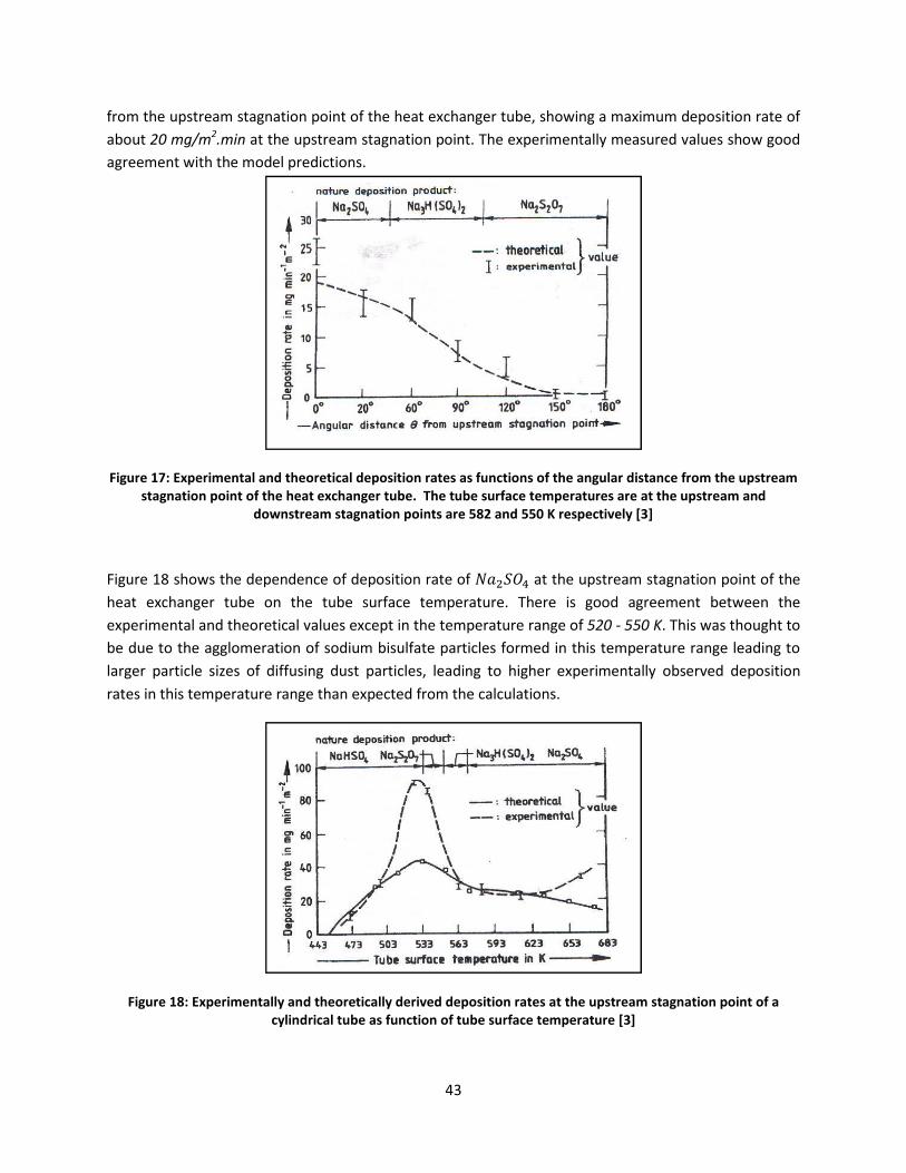
9;!!
R.0V!43*!1SU4.*&V!U4&2)&4(0)!S0()4!0R!43*!3*&4!*FK3&)2*.!41\*5!U30`()2!&!V&F(V1V!,*S0U(4(0)!.&4*!0R!&\014!'1!$7#$'%$K:!&4!43*!1SU4.*&V!U4&2)&4(0)!S0()4J!<3*!*FS*.(V*)4&==W!V*&U1.*,!'&=1*U!U30`!200,!&2.**V*)4!`(43!43*!V0,*=!S.*,(K4(0)UJ!
!
T-B*"#'<U0'=a$#"-,#(.%;'%(&'.5#4"#.-9%;'&#$4)-.-4('"%.#)'%)'A*(9.-4()'4A'.5#'%(B*;%"'&-).%(9#'A"4,'.5#'*$)."#%,').%B(%.-4('$4-(.'4A'.5#'5#%.'#a95%(B#"'.*+#2'':5#'.*+#')*"A%9#'.#,$#"%.*"#)'%"#'%.'.5#'*$)."#%,'%(&'
&4H()."#%,').%B(%.-4('$4-(.)'%"#'L_E'%(&'LLQ'7'"#)$#9.-S#;/'CMD'
!
E(21.*!"B!U30`U!43*!,*S*),*)K*!0R!,*S0U(4(0)!.&4*!0R!��ÌÍ�!&4!43*!1SU4.*&V!U4&2)&4(0)!S0()4!0R!43*!3*&4! *FK3&)2*.! 41\*! 0)! 43*! 41\*! U1.R&K*! 4*VS*.&41.*J! <3*.*! (U! 200,! &2.**V*)4! \*4`**)! 43*!*FS*.(V*)4&=!&),!43*0.*4(K&=!'&=1*U!*FK*S4!()!43*!4*VS*.&41.*!.&)2*!0R!)'1!@!))1!&J!<3(U!`&U!4301234!40!\*!,1*!40!43*!&22=0V*.&4(0)!0R!U0,(1V!\(U1=R&4*!S&.4(K=*U!R0.V*,!()!43(U!4*VS*.&41.*!.&)2*!=*&,()2!40!=&.2*.! S&.4(K=*! U(i*U! 0R! ,(RR1U()2! ,1U4! S&.4(K=*U5! =*&,()2! 40! 3(23*.! *FS*.(V*)4&==W! 0\U*.'*,! ,*S0U(4(0)!.&4*U!()!43(U!4*VS*.&41.*!.&)2*!43&)!*FS*K4*,!R.0V!43*!K&=K1=&4(0)UJ!
!
T-B*"#'<_0'=a$#"-,#(.%;;/'%(&'.5#4"#.-9%;;/'&#"-S#&'&#$4)-.-4('"%.#)'%.'.5#'*$)."#%,').%B(%.-4('$4-(.'4A'%'9/;-(&"-9%;'.*+#'%)'A*(9.-4('4A'.*+#')*"A%9#'.#,$#"%.*"#'CMD'
!

99!!
E(21.*!":!U30`U!43*!,*S*),*)K*!0R!K&=K1=&4*,!,*S0U(4(0)!.&4*U!0R!;!,(RR*.*)4!S&.4(K=*!,(&V*4*.U!0)!41\*!U1.R&K*! 4*VS*.&41.*J! YU! K&)! \*! 0\U*.'*,5! 43*! ,*S0U(4(0)! .&4*U! R0.! =&.2*! S&.4(K=*U! ?1%',! B$! ,(&JA! &.*!2.*&4*.!43&)!43&4!R0.!UV&==*.!S&.4(K=*U!?1%/'!&),!1%15!B$!,(&JAJ!
!
T-B*"#'<[0':5#4"#.-9%;'&#$4)-.-4('"%.#'%)'A*(9.-4('4A'.*+#')*"A%9#'.#,$#"%.*"#'A4"'N%E?OP'&*).'$%".-9;#)'H-.5'&-AA#"#(.'&-%,#.#")'CMD'
<3*!(VS0.4&)4!K0)K=1U(0)!R.0V!43*!.*U*&.K3!014=()*,!()!%*R*.*)K*!];^!(U!43&4!p43*!,*2.**!0R!R01=()2!0R!3*&4! *FK3&)2*.! 41\*U! ,*S*),U! U4.0)2=W! 1S0)! 43*! =0K&4(0)! &),! 4*VS*.&41.*! 0R! 43*! 41\*! U1.R&K*qJ!6&F(V1V! R01=()2! 0KK1.U! &4! 43*! 1SU4.*&V! U4&2)&4(0)! S0()4! 0R! 43*! 41\*J! Y=U05! V&F(V1V! R01=()2! `&U!R01),!40!\*!0KK1..()2!\*4`**)!)'1!&),!))1!&!41\*!U1.R&K*!4*VS*.&41.*UJ!Y=U05!U(i*!0R!43*!,1U4!S&.4(K=*U!R0.V*,!`&U!&)!(VS0.4&)4!S&.&V*4*.!()!43*!V0,*=!K&=K1=&4(0)U5!&),!43*.*R0.*5!&KK1.&4*!V*&U1.*V*)4U!0R!S&.4(K=*! U(i*!,(U4.(\14(0)U5!&KK0.,()2! 40! 43*!&1430.U5!`(==! (VS.0'*! 43*!&SS=(K&\(=(4W!0R! 43*!,*S0U(4(0)!V0,*=J!
4.1.3. Important Findings from Model Studies [16], [18], [17] and [3] Concerning GHIJKL Formation of Particulate Matter on Heat Pipe External Surfaces E.0V! U41,(*U! 43&4! `*.*! ,*UK.(\*,! ()! U1\DU*K4(0)U! 9J"J"! &),! 9J"JC5! 43*! R0==0`()2! &.*! 43*! (VS0.4&)4!R(),()2U!S&.4(K1=&.=W!.*=*'&)4!R0.!43*!R0.V&4(0)!0R!��ÌÍ�!S&.4(K1=&4*!V&44*.>!
"J +1.R&K*!4*VS*.&41.*!0R!43*!3*&4!S(S*!(U!&)!(VS0.4&)4!R&K40.!`3(K3!()R=1*)K*U!43*!,*S0U(4(0)!.&4*!0R! S&.4(K=*UJ! E.0V! %*R*.*)K*! ];^5!V&F(V1V! ,*S0U(4(0)! .&4*U! 0R!��ÌÍ�! `*.*! 0\U*.'*,! R0.! &!KW=(),.(K&=!3*&4!*FK3&)2*.!41\*!&4!41\*!U1.R&K*!4*VS*.&41.*!.&)2*!0R!#C$D##$![J!E.0V!.*R*.*)K*!]"G^5!V&F(V1V!,*S0U(4(0)!.&4*U!0R!��ÌÍ�!`*.*!K&=K1=&4*,!0)!&!.*2*)*.&40.!\.(KM!U1.R&K*!40!\*!0KK1..()2!&4!U1.R&K*!4*VS*.&41.*!0R!&\014!";"$
!
S0()45!(J*J5!()!43*!K&U*!0R!43*!3*43*!3*&4!S(S*J!E(21.*!C$!U30`UV&F(V1V!,*S0U(4(0)!.&4*J!
T-B*"#'EQ0'?95#,%.-9'"#$"#)#(.%.-4
;J -(&V*4*.!0R! 43*!S&.4(K=*U! R0.V.&4*U5! &U! (U! (),(K&4*,!V0,*=! U443&4! U301=,! \*! ,0)*! R0.! 43*! *6*&,'(==*!S=&)4!43&4!K&)!\*!3*=S43*!R=1*!,1K4!(U!0S4(V&=J!
7)! 43*! *'*)4! 43&4! 43*! S=&K*V*)4! 0R! 4R0.V&4(0)! .&4*! 0)! 43*! 3*&4! S(S*! (U! '(..*,1K4(0)! ()!3*&4! 4.&)UR*.!*RR*K4('*)*UU1.R&K*UJ!
+0,(1V!U1=R&4*!S&.4(K1=&4*!V&44*.!K&)!\*K&1U*!(4!(U!&!`*&M=W!&,3*.()2!,*S0U(4\*! .*V0'*,!&),! .*D()U4&==*,!*&K3! 4(V*?;J#!()J!,(&V*4*.!41\*!`(43!4`0!=0)2(41,43*! 3*&4! S(S*5! \043! K0)4&K4! &),!)0)DK4*VS*.&41.*!?#$$DG$$lTA!0R!43*!R=1*!2&U
7)!0.,*.!40!.*)*`!43*!3*&4!4.&)UR*.!S*.1U*,!()!43*!(),1U4.WJ!Y==!K=*&)()2!V*430=()*J!<3*!)*F4!4`0!U1\DU*K4(0)U!?9JC!&),=()*!&),!0)D=()*!K&4*20.(*U!.*US*K4('*=WJ
9#!
*&4!S(S*5!&=0)2!43*!1SS*.V0U4!S&.4!0R!43*!K1.'*,!U1.U!&)!*),!'(*`!0R!43*!3*&4!S(S*5!(),(K&4()2!43*!*FS*K4
!
4('4A'.5#'fA4*;#&g'5#%.'$-$#')54H-(B'*$)."#%,').%B(%.-4('
V*,!V&W!\*!&)043*.! (VS0.4&)4! R&K40.! 43&4!&RR*K4U! 431,(*U! R.0V!%*R*.*)K*! ];^J! <3(U!V(234! \*! &)043*.!V*F3&1U4! 2&U! R.0V! 43*! R=1*! ,1K4! 0R! 43*! 0FWDR1*=! R1.)&SR1=!()!,*4*.V()()2!(R!43*!S=&))*,!S0U(4(0)!0R!43*!3*&4
3*! 3*&4! S(S*! (U! K0)U4.&()*,5! ()! 043*.! `0.,U5! (R! 43*.41&==W! 1)K3&)2*&\=*5! 43*! )*F4! \*U4! U0=14(0)! 40! 43*U!0R! 43*!3*&4!S(S*! (U!S*.(0,(K!K=*&)()2!0R! 43*!3*&4!S
\*!K=*&)*,!\W!S.(V&.(=W!V*K3&)(K&=!K=*&)()2!V*430J!Q)D=()*!K=*&)()2!V*430,U!&.*!S.*R*..*,5!U()K*!43*!<*!&!K=*&)()2! (U! .*c1(.*,J!+()K*! 43*!3*&4!S(S*!2*0V*,()&=!R()UA!&),!43*!U1.R&K*U!40!\*!K=*&)*,!&.*!0)!43*!1K0)4&K4! K=*&)()2!V*430,U! K&)! \*! K0)U(,*.*,5! &=4301U*U!=(V(4U!43*!&SS=(K&\(=(4W!0R!K0)4&K4D4WS*!K=*&)()2!V*
.R0.V&)K*!0R!3*&4!*FK3&)2*.U5!&!'&.(*4W!0R!K=*&)()2!V0,U!K&)!\*!\.0&,=W!K=&UU(R(*,!()40!4`0!K&4*20.(*U>!QRRD,!9J;A!,*UK.(\*!43*!'&.(01U!K0VV0)!K=*&)()2!V*430,J!
.R&K*!&.*&!0R!4*,!.*2(0)!0R!
$4-(.'
3*! R0.V&4(0)!V*&U1.*V*)4!&K*! &4! NNagU!4!S(S*!`(43()!
*! S&.4(K1=&4*!*! S.0\=*V! 0R!S(S*!*F4*.)&=!
,U5!S.(V&.(=W!<Xa!)**,!)04!4.W! (U! U(VS=*!1SS*.!3&=R!0R!123! 43*! 3(23!*430,UJ!
V*430,U!&.*!D=()*!&),!Q)D,U!()!43*!0RRD

9@!!
G)4)'9::MN/#%'!8%1#/#3'F%$;",&'":'C"-8%,'E%1$'DK.;1#3%+'>-+:1.%&'QRRD=()*!V*430,U!&.*!1U1&==W!S*.R0.V*,!`3*)!43*!3*&4!*FK3&)2*.!S*.R0.V&)K*!,*4*.(0.&4*U!\*W0),!&!US*K(R(*,!=(V(45!&),!()'0='*!4&M()2!43*!,*'(K*!014!0R!0S*.&4(0)!R0.!K=*&)()2J!+4*()3&2*)!]"9^!&),!L044!]";^!3&'*! &! '&.(*4W! 0R! 0RRD=()*! K=*&)()2! V*430,U! =(U4*,J! <3*W! K&)! \*! \.0&,=W! K=&UU(R(*,! ()40! K3*V(K&=! &),!V*K3&)(K&=!V*430,UJ!
4.2.1. Chemical Methods T3*V(K&=!V*430,U!&.*! R.*c1*)4=W!1U*,! R0.! K=*&)()2! ()4*.)&=! U1.R&K*U!0R!3*&4!*FK3&)2*.UJ!<3*W!3&'*!&!)1V\*.!0R!&,'&)4&2*U!K0VS&.*,!40!V*K3&)(K&=!K=*&)()2!V*430,U!]"95!";^5!U1K3!&U>!
"J <3*W!&.*!.*=&4('*=W!c1(KM5!
CJ +1.R&K*U!,0!)04!*FS*.(*)K*!V*K3&)(K&=!,&V&2*5!
;J T3*V(K&=!U0=14(0)U!.*&K3!043*.`(U*!()&KK*UU(\=*!&.*&U5!
9J <3*W!&.*!=*UU!=&\0.D()4*)U('*!43&)!V*K3&)(K&=!K=*&)()25!&),!
#J T=*&)()2!K&)!\*!S*.R0.V*,!()!U(41J!
60U4!0R!43*!K3*V(K&=!K=*&)()2!V*430,U!K0)U(U4!0R!R('*!,(U4()K4!S.0K*UU*U5!*&K3!\*()2!V0)(40.*,!R0.!200,!.*U1=4U!\*R0.*!S.0K**,()2!40!43*!)*F4!V*430,J!<3*W!&.*>!
"J Y=M&=()*!K=*&)5!
CJ %()U*U5!
;J YK(,(K!K=*&)5!
9J %()U*U5!&),!
#J N&UU('&4(0)J!
%*R*.*)K*U!]"9^!&),!]";^!2('*!,*4&(=U!&\014!,(RR*.*)4!K=*&)()2!&2*)4U!&),!4WS(K&=!,*S0U(4U!.*V0'*,!1U()2!K3*V(K&=!K=*&)()25!&=430123!U0,(1V!U1=R&4*!(U!)04!0)*!0R!43*!,*S0U(4U!V*)4(0)*,!?()!<&\=*!9!0)!S&2*!;9!0R!%*R*.*)K*!]"9^!&),!<&\=*!T#!()!YSS*),(F!TAJ!
4.2.2. Mechanical Methods <3*U*! V*430,U! ()'0='*! ,(UV&)4=()2! 0R! 43*! `30=*! &SS&.&41U! &),! K=*&)()2! 1U()2! S.*UU1.(i*,! U4*&V!?U4*&VD\=&U4()2A! 0.! `&4*.! ?3W,.0D\=&U4()2AJ! +&),! K&)! \*! &,,*,! 40! 43*! K=*&)()2!`&4*.! 40! (VS.0'*! 43*!K=*&)()2!*RR(K(*)KWJ!%(2(,!=&)K()2!&),!R=*F(\=*!=&)K()2!&.*!&=U0!S0S1=&.!V*430,U!1U*,!40!K=*&)!43*!()4*.)&=!U1.R&K*U!0R!3*&4!*FK3&)2*.! 41\*UJ!b&.(01U!V*430,U!0R!K=*&)()2!*F4*.)&=!U1.R&K*U!&.*!&=U0!,*UK.(\*,! ()!%*R*.*)K*!]"9^5!U1K3!&U!3(23!&),!1=4.&!3(23!S.*UU1.*!S1VSU5!K=*&)()2!)0ii=*U5!41.\0O*4U5!S1U3!&),!S1==!)0ii=*U!&),!.040.O*4UJ!Y140V&4(K!V*K3&)(K&=!K=*&)()2!V*430,!R0.!*F4*.)&=!U1.R&K*U!`(43!3(23DS.*UU1.*!`&4*.!U**VU!40!\*!&!V*430,!0R!()4*.*U4!R0.!43*!K=*&)()2!0R!43*!<XaJ!<3(U!K=*&)()2!4&M*U!S=&K*!`(43014!&)W!&,,(4('*U5!&),!(U!*RR*K4('*J!

9G!!
G)B)'9#MN/#%'!8%1#/#3'F%$;",&':"+'C"-8%,'E%1$'DK.;1#3%+'>-+:1.%&'<3*U*!K=*&)()2!V*430,U!&.*!S*.R0.V*,!K0)4()101U=W!&),d0.!S*.(0,(K&==W! 40!.*)*`!43*!3*&4!*FK3&)2*.!3*&4!4.&)UR*.!S*.R0.V&)K*5!&U!0SS0U*,!40!0RRD=()*!V*430,UJ!Y2&()5!43*W!K&)!\*!K=&UU(R(*,!()40!K3*V(K&=!&),!V*K3&)(K&=!V*430,UJ!
4.3.1. Chemical Methods N&.4(K1=&4*!R01=()2!()!3*&4!*FK3&)2*.U!(U!1U1&==W!V(4(2&4*,!'(&!0)D=()*!K3*V(K&=!V*&)U!\W!43*!&,,(4(0)!0R!U1.R&K4&)4U! 0.! ,(US*.U&)4U! ]"9^! 0.! \W! 43*! ()O*K4(0)! 0R! K3*V(K&=! U0=14(0)U! K&==*,! f,0U()2g! ]";^J! <3(U! (U!*US*K(&==W! &SS=(K&\=*! R0.! ()4*.)&=! 41\*U!0R!3*&4!*FK3&)2*.U!`3*.*!&! =(c1(,!V*,(1V! (U!1U*,! 40! 4.&)UR*.!3*&4J!LW!.*,1K()2!43*!U1.R&K*!4*)U(0)5! =&.2*!S&.4(K=*U!K&)!\.*&M!,0`)!()40!UV&==*.!S&.4(K=*U5!`3(K3!&.*!K&..(*,! &`&W! \W! 43*! 3*&4! *FK3&)2*.! =(c1(,! (4U*=RJ! <&\=*! T#! ()! YSS*),(F! T! ]";^! 2('*U! U0V*! K3*V(K&=!K=*&)()2!&2*)4U!1U*,!()!43*!(),1U4.WJ!
4.3.2. Mechanical Methods b&.(01U!0)D=()*!V*K3&)(K&=!S&.4(K1=&4*!R01=()2!V(4(2&4(0)!V*430,U!3&'*!\**)!,*'*=0S*,5!\&U*,!0)!43*!R0==0`()2!V*K3&)(UVU>!
"J +30.4D4(V*! 0'*.3*&4()2! 0R! 43*! 3*&4! 4.&)UR*.! U1.R&K*U! ?,(RR*.*)4! 43*.V&=! *FS&)U(0)! 0R! 41\*U! &),!41\*!,*S0U(4U!V&W!K&1U*!K.&KM()2!0R!43*!,*S0U(45!&),!43*!K.&KM*,!,*S0U(4!R&==U!0RR5!&),!(U!,*S0U(4*,!0)!43*!\0440V5!0.!K&..(*,!&`&W!\W!43*!K(.K1=&4()2!R=1(,A5!
CJ 6*K3&)(K&=!'(\.&4(0)!0R!3*&4!4.&)UR*.!U1.R&K*U5!
;J YK01U4(K!'(\.&4(0)!0R!3*&4!4.&)UR*.!U1.R&K*U5!
9J 7)K.*&U*,!U3*&.!U4.*UU!&4!R=1(,!,*S0U(4!()4*.R&K*5!&),!
#J %*,1K*,!&,3*U(0)!0R!,*S0U(4UJ!
Y!)1V\*.!0R!4*K3)(c1*U!&.*!&'&(=&\=*!?%*R*.*)K*!]";^A!R0.!.*,1K()2!43*!*RR*K4U!0R!R01=()25!U0V*!0R!`3(K3!&.*!V*)4(0)*,!\*=0`>!
"J T(.K1=&4(0)!0R!US0)2*!.1\\*.!\&==U5!
CJ L.1U3!&),!T&2*!UWU4*VU5!
;J Y(.!0.!2&U!()O*K4(0)5!
9J 6&2)*4(K!,*'(K*U5!!
#J +004!\=0`*.U5!
@J +0)(K!4*K3)0=02W5!
GJ P&4*.!`&U3()25!

9B!!
BJ +304!K=*&)()25!
:J a&='&)(K!S.04*K4(0)5!&),!
"$J eU*!0R!7)U*.4UJ!
7)!=(c1(,DR=0`!4WS*!3*&4!*FK3&)2*.U5!.*'*.U&=!0R!R=0`!,(.*K4(0)!()!K0)O1)K4(0)!`(43!&!U30.4D4(V*!()K.*&U*!0R!R=0`!'*=0K(4W!(U!U0V*4(V*U!1U*,!&U!&!V*430,!0R!K=*&)()2!014!`*&M=W!&,3*.()2!,*S0U(4UJ!!
G)G)'C%1&/O8%'!8%1#/#3'F%$;",&':"+'!8%1#/#3'E%1$'5/=%'>-+:1.%&'5%+/",/.188@'!
YSS*),(F!Y!2('*U!&!=(U4!0R!K0VS&)(*U!V*)4(0)*,!()!%*R*.*)K*!]"9^!43&4!&.*!()!43*!\1U()*UU!0R!S.0'(,()2!3*&4!*FK3&)2*.!K=*&)()2!U*.'(K*U!&),!,*'(K*UdS.0,1K4Ud*c1(SV*)4UJ!/W,.0D\=&U4()2d+4*&VD\=&U4()2!&),!+004\=0`*.! 4*K3)0=02(*U! ]"9^! U**V! 40! \*! S.0V(U()2!`&WU! 0R! K=*&)()2! 43*! 3*&4! S(S*! *F4*.)&=! U1.R&K*U!S*.(0,(K&==W!&),!`(43!.*=&4('*!*&U*!0R!0S*.&4(0)J! 7)!S&.4(K1=&.5! 43*!+004\=0`*.!4*K3)0=02W!U**VU!40!\*!V0U4!S.0V(U()2!U()K*! ()!%*R*.*)K*! ]"9^5! (4! (U!&=U0!V*)4(0)*,!43&4!pT=*&)()2!UWU4*VU!&.*! ()U4&==*,!`(43!S.0S*.!.*U1=4U!()!.*2*)*.&4('*!2&Ud&(.!3*&4*.Uq!?%*R*.*)K*!]"9^!S&2*!CB$!8!pT=W,*!L*.2*V&))!T=*&)()2!<*K3)0=02W! R0.! /*&4! XFK3&)2*.q5! +4*S3&)! +(V0)! H! %(K3&.,! o&K3&W5! T=W,*! L*.2*V&))5! -DP*U*=5!a*.V&)WAJ! <3*! R0==0`()2! U1\DU*K4(0)! 2('*U! &)! 0'*.'(*`! 0R! U004\=0`*.! 4*K3)0=02W! &U! ,*UK.(\*,! ()!%*R*.*)K*!]"9^J!
!
4.4.1. Sootblower Technology +004\=0`*.! 4*K3)0=02W! \&U(K&==W! .*=(*U! 0)! 43*! M()*4(K! *)*.2W!0R! &! \=0`()2! O*4!`3(K3! (U! 2*)*.&4*,! ()! &!'*)41.(! )0ii=*! R.0V!S.*UU1.(i*,!2&U5! 40!S*.R0.V!K=*&)()2!0R!3*&4!*FK3&)2*.! U1.R&K*U! R.0V!S&.4(K1=&4*!,*S0U(4UJ!Y(.5!`&4*.!&),!U4*&V!&.*!1U*,!&U!\=0`()2!V*,(&J! 74! (U!&=U0!V*)4(0)*,!43&4! ()!0.,*.! 40!V**4!*&K3!(),('(,1&=!K=*&)()2!.*c1(.*V*)4!\&U(K!,*U(2)!R*&41.*U!3&'*!40!\*!K0)U(,*.*,5!U1K3!&U>!
• +*=*K4()2!43*!.(234!U004\=0`*.!4WS*5!
• XK0)0V(K!&..&)2*V*)4!0R!U004\=0`*.U5!
• +*=*K4(0)!0R!43*!.*c1(.*,!)0ii=*!2*0V*4.W5!
• T300U()2!43*!S.0S*.!\=0`()2!S.*UU1.*5!&),!
• QS*.&4()2!U1SS0.4J!
+004\=0`*.U!0R!,(RR*.*)4!4WS*U!3&'*!\**)!,*'*=0S*,!R0.!,(RR*.*)4!&SS=(K&4(0)U5!U1K3!&U>!
_0)2!.*4.&K4&\=*!\=0`*.!?R0.!U1S*.3*&4*.!&.*&A5!3*=(K&=!\=0`*.!?R0.!*K0)0V(i*.!`(43!UV0043!41\*A5!`&==!\=0`*.! ?R0.! R1.)&K*! &.*&! 8! U4*&V! &),!`&4*.D0S*.&4*,A5! .04&4()2! *=*V*)4! \=0`*.! ?R0.! 3*&4! *FK3&)2*.!`(43! UV0043! 41\*UA5! .&M*! \=0`*.! ?R0.! *K0)0V(i*.!`(43! R()! 41\*UA5!P&4*.! K&))0)u! ?R0.! R1.)&K*! &.*&5!

9:!!
30SS*.5! 043*.! R1.)&K*! K3&V\*.UA5! =&)K*D4WS*!`&4*.!\=0`*.! ?R0.! R1.)&K*! &.*&!&),!043*.! &SS=(K&4(0)UA5!&),!U004\=0`*.U!R0.!US*K(&=!&SS=(K&4(0)UJ!
<3*! \=0`()2!V*,(1V! K&)! \*! U4*&V5! &(.! 0.! `&4*.J! E0.! 43*! 3*&4! S(S*5! U()K*! 43*.V&=! U30KM!`(==! \*! &)!(VS0.4&)4!K.(4*.(0)!40!\*!K0)U(,*.*,5!&),!&=U0!U()K*!43*!K=*&)()2!V*430,!(U!*)'(U(0)*,!40!\*!&)!0)D=()*!V*430,5!&(.!&4!U(V(=&.!4*VS*.&41.*U!?&U!43*!3*&4!S(S*!U1.R&K*!4*VS*.&41.*UA!(U!&!R*&U(\=*!0S4(0)J!E0.!43(U5!.*DK(.K1=&4*,!&),!R(=4*.*,!R=1*!2&U!V&W!\*!1U*,!`(43!U004\=0`*.UJ!
4.4.2. Gears and Vibrators (Rapping Device) %&SS()2!2*&.U!&),!'(\.&40.U!K&)!\*!1U*,!R0.!K=*&)()2!()!K&U*!0R!3*&4()2!U1.R&K*!K0&4()2U!43&4!&.*!43(KM!U=&22()2!]"9^J!T=*&)()2! ()!43(U!K&U*! (U!K&1U*,!\W!43*!'(\.&4(0)!S.0K*UU!&K4()2!0)!43*!3*&4()2!U1.R&K*J! 7)!K&U*!0R!43*!3*&4!S(S*5!43(U!V*430,!3&U!43*!&,'&)4&2*!0R!\*()2!()U4&==*,!0)D=()*!&),!&=U0!)04!()4.0,1K()2!&)W!43*.V&=!U30KM!40!43*!UWU4*VJ!<3*!*RR*K4('*)*UU!0R!43(U!4*K3)(c1*5!30`*'*.5!,*S*),U!0)!43*!)&41.*!0R!43*!,*S0U(4!(4U*=R5!&),!43*!S.*K&.(01U)*UU!0R!43*!3*&4!S(S*!UWU4*V!()U4&==&4(0)J!<3(U!(U!&)043*.!V*430,!43&4!U301=,!\*!K0)U(,*.*,!&)!&=4*.)&4('*!40!,(.*K4!K0)4&K4!K=*&)()2!V*430,UJ!T=W,*!L*.2*V&))!7)KJ!?0)*!0R!43*!K0)4&K4U!=(U4*,!()!YSS*),(F!YA!U**VU!40!\*!M)0`=*,2*&\=*!0R!43(U!S.0K*,1.*J!
!
!

#$!!
P)'5+"="&%,'DK=%+/?%#$&':"+'Q%$%+?/#/#3'E"R'$"'!"#$+"8'>",/-?'>-8:1$%'51+$/.-81$%'C"+?1$/"#'"#'$;%'E%1$'5/=%'"+'$"'!8%1#'$;%'E%1$'5/=%'!
<3(U!U*K4(0)!014=()*U!&!S=&)!R0.!*FS*.(V*)4U!43&4!&.*!40!\*!K0),1K4*,!&4!43*!NNa!S=&)4!&4!6*&,'(==*5!NY!()!0.,*.!40>!
"J 6*&U1.*!&),!,*4*.V()*!43*!'&.(&\=*U! 43&4!&RR*K4! 43*! .&4*!0R! R0.V&4(0)!0R!��ÌÍ�!S&.4(K1=&4*!=&W*.!0)!43*!3*&4!S(S*5!&),!43*.*\W!,*4*.V()*!43*!0S4(V&=!=0K&4(0)!0R!43*!3*&4!S(S*!()!43*!R=1*!,1K45!
CJ 60)(40.!43*!,*K.*&U*!()!3*&4!4.&)UR*.!*RR*K4('*)*UU!0R!43*!3*&4!S(S*!()!K0)'*.4()2!43*!&'&(=&\=*!43*.V&=!*)*.2W!40!*=*K4.(K&=!*)*.2W!?'(&!43*!<Xa!V0,1=*A!!&U!&!R1)K4(0)!0R!,1.&4(0)!0R!0S*.&4(0)5!&),!
;J eU*!43*!V0)(40.()2!4*K3)(c1*!40!4*U4!43*!=*'*=!0R!.*K0'*.W!0R!3*&4!4.&)UR*.!*RR*K4('*)*UU!0R!43*!3*&4!S(S*!,1*!40!K=*&)()2!43*!3*&4!S(S*!1U()2!4`0!K=*&)()2!V*430,UJ!
7)! 0.,*.! 40! 1),*.U4&),! 43*! R0.V&4(0)! 0R! ��ÌÍ�! S&.4(K1=&4*! R0.V&4(0)! .&4*5! 43*! 43*0.*4(K&=! &),!*FS*.(V*)4&=!.*U1=4U!R.0V!.*U*&.K3!`0.M!43&4!3&U!\**)!K0),1K4*,!0)!=&\0.&40.W!UK&=*!?&U!,(UK1UU*,!()!U*K4(0)! 9J"! &),! (4U! U1\DU*K4(0)U! ()! 43(U! .*S0.4A! `(==! \*! 1U*,J! YKK0.,()2! 40! %*R*.*)K*! ];^5! 43*! V0U4!(VS0.4&)4! S&.&V*4*.! 43&4! &RR*K4U! 43*! .&4*! 0R! ,*S0U(4(0)! 0R! ��ÌÍ�! S&.4(K1=&4*! (U! 43*! U1.R&K*!4*VS*.&41.*! 0R! 43*! 3*&4! S(S*J! E.0V! ()R0.V&4(0)! U1SS=(*,! \W! NNa5! 43*! S&.&V*4*.U! 43&4! &.*! \*()2!V*&U1.*,!K1..*)4=W!&.*>!
"J <3*! '0=4&2*! Yá^! &K.0UU! 43*! <Xa! &),! *=*K4.(K! K1..*)4! Yâ^! ,.&`)! R.0V! 43*! <Xa! &U! 4(V*D3(U40.W!'&.(&\=*U5!
CJ <3*! 3*&4! S(S*! U1.R&K*! V*4&=! 4*VS*.&41.*U! Yv�,v�,v¹,v�,vÙ^! &4! 43*! =0K&4(0)U! &U! (),(K&4*,! ()!E(21.*!C"J!
<3*! 4*VS*.&41.*U! K1..*)4=W! \*()2! V0)(40.*,! `(==! \*! U1RR(K(*)4! 40! ,*4*.V()*! 43*! 4*VS*.&41.*!,(U4.(\14(0)!0)!43*!*F4*.)&=!U1.R&K*!0R!43*!3*&4!S(S*J!7)!&,,(4(0)!40!43(U!()R0.V&4(0)5!(4!`(==!&=U0!\*!1U*R1=!40!M)0`!43*!R=1*!2&U!4*VS*.&41.*!()!43*!'(K()(4W!0R!43*!3*&4!S(S*!&),!&=U0!43*!R=1*!2&U!4*VS*.&41.*!&U!43*!2&U!S&UU*U!43.0123!43*!,0`)K0V*.!R.0V!43*!R1.)&K*J!E(21.*!CC!U30`U!43*!&,,(4(0)&=!43*.V0K01S=*!=0K&4(0)U!43&4!K&)!\*!1U*,!40!,*4*.V()*!43*!4*VS*.&41.*!K3&)2*!0R!43*!R=1*!2&UJ!<3(U!()R0.V&4(0)!`(==!\*!1U*R1=!40!K0VS&.*!`(43!E(21.*!""!R.0V!%*R*.*)K*!]"@^5!`3(K3!2('*U!43*!,(U4.(\14(0)!0R!43*!404&=!U0,(1V!()!*F3&1U4!2&U!R.0V!&!2&UDR(.*,!R=&4!2=&UU!R1.)&K*!?`3(K3!(U!43*!U&V*!&U!43&4!()!NNa!S=&)4!()!6*&,'(==*5!NY!8!&=430123!(4! (U!)04!K=*&.!`3*43*.!43*!0)*!V*)4(0)*,!()!%*R*.*)K*!]"@^!(U!&)!0FWDR1*=!4WS*!R1.)&K*A!&U!&!R1)K4(0)!0R!2&U!4*VS*.&41.*J!<3(U!`(==!2('*!&)!(),(K&4(0)!0R!`3&4!43*!.*=&4('*!,*S0U(4(0)!0R!U0,(1V!`01=,!\*!()!43*!*F3&1U4!2&U!&U!��ÌÍ�!S&.4(K1=&4*!R0.!,(RR*.*)4!S0U(4(0)U!0R!43*!3*&4!S(S*!()!43*!R=1*!,1K4J!
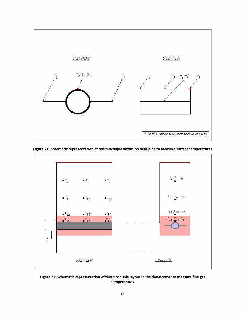
#"!!
!
T-B*"#'E<0'?95#,%.-9'"#$"#)#(.%.-4('4A'.5#",494*$;#';%/4*.'4('5#%.'$-$#'.4',#%)*"#')*"A%9#'.#,$#"%.*"#)'
!
T-B*"#'EE0'?95#,%.-9'"#$"#)#(.%.-4('4A'.5#",494*$;#';%/4*.'-('.5#'&4H(94,#"'.4',#%)*"#'A;*#'B%)'.#,$#"%.*"#)'

#C!!
Y)043*.!(VS0.4&)4!R&K40.!&RR*K4()2!43*!,*S0U(4(0)!.&4*!0)!&!KW=(),.(K&=!41\*!(U!43*!&)21=&.!,(U4&)K*!R.0V!43*!1SU4.*&V!U4&2)&4(0)!S0()4! ?.*R*.! E(21.*!"G!&),!E(21.*!C$AJ!YKK0.,()2! 40!%*R*.*)K*! ];^5!V&F(V1V!,*S0U(4(0)! .&4*! 0R!��ÌÍ�! `&U! 0\U*.'*,! &4! 43*! 1SU4.*&V! U4&2)&4(0)! S0()4! ?&U! U30`)! ()! E(21.*! "GAJ!YKK0.,()2=W5! &! UK3*V&4(K! .*S.*U*)4&4(0)! 0R! 43*! fR01=*,g! 3*&4! S(S*! `(43! &)! *FS*K4*,! S&.4(K1=&4*!,*S0U(4(0)! S.0R(=*! (U! U30`)! ()! E(21.*! C$J! <3(U! K&)! \*! K3&==*)2()2! 40! V*&U1.*5! \14! (U! S0UU(\=*! \W!V*&U1.*V*)4U! 0R! 43(KM)*UU! 0R! 43*! ��ÌÍ�! ,*S0U(4! =&W*.! &4! '&.(01U! &)21=&.! ,(U4&)K*! =0K&4(0)U! ?&U!UK3*V&4(K&==W!U30`)!()!E(21.*!C;A!&4!.*21=&.!()4*.'&=U!0R!4(V*!\W!4&M()2!43*!,*'(K*!0RRD=()*J!
!
T-B*"#'EM0'?95#,%.-9'"#$"#)#(.%.-4('4A';49%.-4()'4('.5#'5#%.'$-$#'.4'%))#))'.5#'#AA#9.'4A'%(B*;%"'&-).%(9#'A"4,'.5#'*$)."#%,').%B(%.-4('$4-(.'G;49%.-4('^V^J'4('GHIJKL'&#$4)-.-4('"%.#'
<3*! 43(.,! &),!S*.3&SU! 43*! =*&U4! ()'*U4(2&4*,! R&K40.! 43&4! &RR*K4U! 43*! S&.4(K1=&4*! ,*S0U(4(0)! .&4*! (U! 43*!(),('(,1&=! S&.4(K1=&4*! U(i*U5! &U! U30`)! ()! E(21.*! ":! &),! &U! V*)4(0)*,! ()! 43*! K0)K=1U(0)U! ,.&`)! \W!%*R*.*)K*!];^J!<3*!,*S0U(4(0)!.&4*U!()!E(21.*!":!`*.*!,*.('*,!R.0V!43*!V&43*V&4(K&=!V0,*=v!3*)K*!43*W!&.*!43*!43*0.*4(K&=!'&=1*U!0R!,*S0U4(0)!.&4*U!0R!S&.4(K=*U!0R!,(RR*.*)4!,(&V*4*.UJ!N1\=(U3*,!,&4&!0)!43*!S&.4(K1=&4*!U(i*!,(U4.(\14(0)!V*&U1.*,!R.0V!4`0!R1.)&K*U!V*=4()2!R=()4!2=&UU!&),!&V\*.!2=&UU!.*US*K4('*=W!(U!U30`)!()!.*S.0,1K*,!R.0V!%*R*.*)K*!]9^J!YKK0.,()2!40!%*R*.*)K*!]9^5!S&.4(K=*U!()!43*!R=1*!2&U*U!R.0V!43*U*!R1.)&K*U!`*.*!\*4`**)!$J$#!&),!$J#!B$J!%*R*..()2!40!E(21.*!":5!(R!43*!S&.4(K=*!U(i*!,(U4.(\14(0)!0R!43*!��ÌÍ�! R0.V*,! R.0V! 43*! R=1*! 2&U*U! ()! 43*! 0FWDR1*=! R1.)&K*! &4! 43*! NNa! S=&)4! ()!6*&,'(==*5! NY! (U!V*&U1.*,! R.0V! R=1*! 2&U! U&VS=*U5! 43*! ,*S0U(4(0)! .&4*U! ?&U! S.*,(K4*,! \W! 43*! V&43*V&4(K&=! V0,*=! \W!614U&*.U!*4!&=J!];^A!K&)!\*!S.*,(K4*,!R0.!43*!,(RR*.*)4!S&.4(K=*!,(&V*4*.U5!&),!()4*2.&4*,!40!2*4!43*!404&=!,*S0U(4(0)!.&4*J!7)!%*R*.*)K*!]9^5!&!U&VS=()2!4.&()!`(43!<*R=0)!R(=4*.U!`&U!1U*,!40!K0==*K4!43*!S&.4(K1=&4*!V&44*.!&),!*=*K4.0)!S3040V(K.02.&S3U!`*.*!1U*,!R0.!,*4*.V()()2!43*!S&.4(K=*!U(i*!,(U4.(\14(0)!R.0V!43*!K0==*K4*,! U&VS=*UJ! b&.(01U! 4*K3)(c1*U! U1K3! &U! +K&))()2! X=*K4.0)! 6(K.0UK0SW! ?+X6A5! -0SS=*.! _&U*.!+K&44*.()2! ?-_+A5! _&U*.! -(RR.&K4(0)5! nD%&W! +*,(V*)4&4(0)5! T*)4.(R12&=! +*,(V*)4&4(0)5! X=*K4.(K&=! o0)*!

#;!!
+*)U()2!*4KJ!&.*!1U*,!R0.!,*4*.V()()2!43*!S&.4(K=*!U(i*!,(U4.(\14(0)UJ!E1.43*.! ()'*U4(2&4(0)!)**,U!40!\*!,0)*!40! R(),!014!`3&4!V*430,!`(==!\*!\*U4!U1(4*,! R0.! 43*!U(41&4(0)!&4!3&),5! 43&4! (U5!3(23!4*VS*.&41.*!*F3&1U4!2&U!K0)4&)()()2!S&.4(K1=&4*!V&44*.!43&4!(U!V&()=W!K0VS.(U*,!0R!()0.2&)(K!U&=4UJ!
!
T-B*"#'EP0'!%".-9;#')-\#'&-)."-+*.-4('4A'#AA;*#(.)'A"4,'.H4'B;%))'A*"(%9#)'CPD'
E.0V!Xc1&4(0)! ?""A! ()! U*K4(0)!;JC!0R! 43(U! .*S0.45! 43*! '&.(&\=*U! &RR*K4()2! K0)'*K4(0)!3*&4! 4.&)UR*.! .&4*!R.0V!43*!3*&4!S(S*!40!43*!*F3&1U4!2&U!?43*!,(.*K4(0)!0R!K0)'*K4(0)!3*&4!4.&)UR*.!.&4*! (U! R.0V!43*!3*&4!S(S*!40!43*!R=1*!2&U!&U!K0)R(.V*,!`(43!NNa!D!U**!%*R*.*)K*!]C;^A!&.*>!
"J o�! D! 43*!K0)'*K4(0)!3*&4!4.&)UR*.!K0*RR(K(*)45!
CJ UtXÄVr!D! 404&=!U1.R&K*!&.*&!0R!3*&4!S(S*!014*.!U1.R&K*5!
;J v�!! D! &\U0=14*!2&U!4*VS*.&41.*5!&),!
9J vg!! D! &\U0=14*!U1.R&K*!4*VS*.&41.*J!
Z04*! 43&4!vg!V&W! )04! \*!*c1&=! 40!v�,s! 43*! 4*VS*.&41.*!0R! 43*! 014*.!V*4&=! U1.R&K*!0R! 43*! 3*&4! S(S*!
?`3(K3! (U!\*()2!V*&U1.*,!&4!43*!NNa!S=&)4!&U!v�5!v�5!v¹5!v�!&),!vÙ! D!U**!E(21.*!C"A5!*US*K(&==W!`3*)!&!S&.4(K1=&4*!=&W*.!0R!��ÌÍ�!(U!S.*U*)4!0)!43*!3*&4!S(S*J!6*&U1.()2!vg!V&W!\*!,(RR(K1=4v!&!\*44*.!V*430,!0R! *U4(V&4()2! vg! R.0V! v�,s! `(==! \*! 40! V*&U1.*! 43*! 43*.V&=! K0),1K4('(4W! ?R.0V! =&\0.&40.W! UK&=*!
*FS*.(V*)4UA!0R!43*!��ÌÍ�!S&.4(K1=&4*!=&W*.!&),!43*)!K&=K1=&4*!vg!?E(21.*!BA!1U()2!V*&U1.*,!3*&4!R=1F!_ifrWhb! 43.0123! 43*! S&.4(K1=&4*! =&W*.5! V*&U1.*,! '&=1*U! 0R! V*4&=! 014*.! U1.R&K*! 4*VS*.&41.*! ?v�,s! ()!E(21.*!BA!&),! R=1*!2&U! 4*VS*.&41.*! ?v�! ()!E(21.*!BA5!&),!V*&U1.*,!S&.4(K1=&4*! =&W*.! 43(KM)*UU!_`VWXbJ!<3*!&\U0=14*!2&U!4*VS*.&41.*!v�!V&W!\*!0\4&()*,!&U!43*!&'*.&2*!0R!!v�Ù5!v��!&),!v�²!?U**!E(21.*!CCAJ!

#9!!
<3*!K3&)2*!()!.&,(&4(0)!3*&4!4.&)UR*.!.&4*!K&)!\*!V0)(40.*,!\W!M)0`()2!43*!&\U0.S4('(4W!_�g{sxVWVb!0R!43*!��ÌÍ�! S&.4(K1=&4*! =&W*.! &),! 43*! U1.R&K*! 4*VS*.&41.*! _vg{sxVWVb! `3*)! 43*! 3*&4! S(S*! U1.R&K*! (U!K0'*.*,! `(43!��ÌÍ�! S&.4(K1=&4*! =&W*.J! YKK0.,()2! 40! %*R*.*)K*! ]C;^5! 43*! &\U0.S4('(4W! 0R! 43*! US*K(&=!K0&4()2!_�gy{Wxrb!0)!43*!3*&4!S(S*!1SS*.!U1.R&K*!(U!$J:9v!3*)K*5!R.0V!Xc1&4(0)!?@A!()!U*K4(0)!;JC!0R!43(U!
.*S0.45!.&,(&4(0)!3*&4!4.&)UR*.!.&4*U!K&)!\*!K0VS14*,!&4!&)W!()U4&)4!0R!4(V*!&U>!
ifwxVy{Wxr T Ug�dg��gy{Wxr �_vdb� \ _vgy{Wxrb��! DDDDDDDDDDDDDDDDDDDDDDDDDDDDDDDDDDDDDDDDDDDDDDDDDDDDDDDDDDDDDDD! ?@&A!
&),!
ifwxV{sxVWV T Ug�dg��g{sxVWV �_vdb� \ _vg{sxVWVb��! ! ?@\A!
!
Z04*!43&4!()!Xc1&4(0)!?@&A5!vgy{Wxr T v�,s!`3*.*&U!()!Xc1&4(0)!?@\A5!vg{sxVWV ã v�,s!\14!vg!&U!*U4(V&4*,!
R.0V!Xc1&4(0)!?A!\W!43*!S.*'(01U=W!,(UK1UU*,!V*430,!?S&2*!9B!0R!43(U!.*S0.4A!K01=,!\*!1U*,!R0.!vg{sxVWVJ!L14! 43*!V&O0.!,(RR*.*)K*!\*4`**)!ifwxVy{Wxr! &),!ifwxV{sxVWV! (U! ,1*! 40!�gy{Wxr! ?:;CB5! &KK0.,()2! 40!%*R*.*)K*!]C;^A! \*()2!V1K3! 2.*&4*.! 43&)!�g{sxVWV! ?E.0V! <&\=*! G5!�! R0.! &! `3(4*! YÞÌÍ�^! K0&4()2!`(43! S0=W'()W=!&=K030=! (U!:;:>5!&KK0.,()2!40!%*R*.*)K*! ]:^AJ!Y=U05!U()K*!43*!3*&4!4.&)UR*.! ()40!43*!3*&4!S(S*! (U!*)4(.*=W!,1*!40!.&,(&4(0)!?43*!K0)'*K4(0)!(U!R.0V!43*!3*&4!S(S*!40!43*!R=1*!2&U5!&KK0.,()2!40!Xc1&4(0)!?@A!&),!R.0V!()R0.V&4(0)!&\014! 2&U! &),!3*&4! S(S*! U1.R&K*! 4*VS*.&41.*U! ()! %*R*.*)K*! ]C;^A5! &),! U()K*! 43*!`0.M()2!R=1(,!?U0,(1VA!()!43*!3*&4!S(S*!(U!&4!&!K0)U4&)4!4*VS*.&41.*!?@9:lT!R.0V!%*R*.*)K*!]C;^A!&),!S.*UU1.*!
?@JB:!MN&!D!&\U0=14*A5!43(U!'&.(&4(0)!`(==!,(K4&4*!43*!K3&)2*!()!43*!S0`*.!014S14!jf sth!`3(=*!43*!3*&4!S(S*!(U!()!0S*.&4(0)J!
7)!0.,*.!40!V0)(40.!43*!3*&4!4.&)UR*.!*RR*K4('*)*UU!0R!43*!3*&4!S(S*5!43*!S0`*.!014S14!_jf sth T á Ü âb!!R.0V!43*!<Xa!V0,1=*!(U!\*()2!V0)(40.*,!&4!43*!NNa!S=&)4!&U!R1)K4(0)!0R!4(V*!0R!0S*.&4(0)J!<3*!,*K.*&U*!
()! 3*&4! 4.&)UR*.! *RR*K4('*)*UU! 0R! 43*! 3*&4! S(S*! `(==! \*!V&)(R*U4*,! &U! &! ,*K.*&U*! ()!jf sth! 0'*.! 4(V*J!%*R*.*)K*! ]";^! 3&U! U0V*! 4*K3)(c1*U! =(U4*,! R0.! &UU*UU()2! 3*&4! *FK3&)2*.! S*.R0.V&)K*! 43.0123!&Kc1(U(4(0)! 0R! S=&)4! ,&4&J! Q)*! 0R! 43*! &UU*UUV*)4! 4*K3)(c1*U! (U! V0)(40.()2! V*&)! R01=()2! .*U(U4&)K*!'*.U1U!,&WU!0)!U4.*&V5!&),!43*!*FS*K4*,!4.*),!R0.!R01=()2DS.0)*!3*&4!*FK3&)2*.U!(U!&)!()K.*&U*!()!V*&)!R01=()2!.*U(U4&)K*J!<3(U5!30`*'*.5!(U!*c1('&=*)4!40!V0)(40.()2!43*!S0`*.!014S14!R.0V!43*!<Xa!()!43*!K&U*!0R!43*!3*&4!S(S*J!
<3(U!V0)(40.()2!4*K3)(c1*!K&)!\*!1U*,!R0.!&UU*UU()2!43*!*RR*K4('*)*UU!0R!,(RR*.*)4!K=*&)()2!V*430,U!&U!`*==J!7)!0.,*.!40!,0!43(U5!0)*!)**,U!40!M)0`>!
"J jf sth,qrqhqx{!D!(J*J5!S0`*.!014S14!()(4(&==W5!`3*)!43*!3*&4!S(S*!(U!fK=*&)g!CJ jf sth,§WdswW!D!(J*J5!S0`*.!014S14!\*R0.*!K=*&)()2!1U()2!0)*!0R!43*!K=*&)()2!V*430,U!\*()2!4*U4*,!
0145!&),!
;J jf sth,xdhWw!D!(J*J5!S0`*.!014S14!&R4*.!K=*&)()2!(U!K0VS=*4*,J!
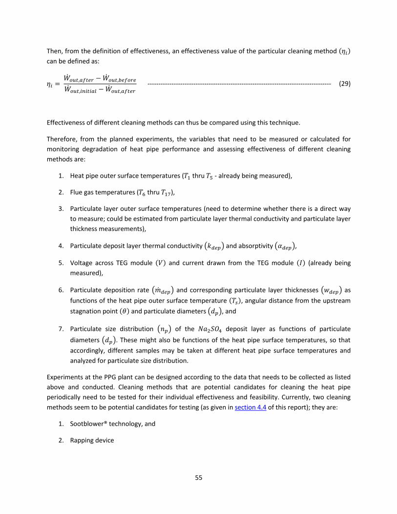
##!!
<3*)5!R.0V!43*!,*R()(4(0)!0R!*RR*K4('*)*UU5!&)!*RR*K4('*)*UU!'&=1*!0R!43*!S&.4(K1=&.!K=*&)()2!V*430,!Yäq^!K&)!\*!,*R()*,!&U>!!
äq T jf sth,xdhWw \ jf sth,§WdswWjf sth,qrqhqx{ \ jf sth,xdhWw ! DDDDDDDDDDDDDDDDDDDDDDDDDDDDDDDDDDDDDDDDDDDDDDDDDDDDDDDDDDDDDDDDDDDDDDDDDDDDDDDDDDDD! ?C:A!
!
XRR*K4('*)*UU!0R!,(RR*.*)4!K=*&)()2!V*430,U!K&)!431U!\*!K0VS&.*,!1U()2!43(U!4*K3)(c1*J!
<3*.*R0.*5! R.0V! 43*! S=&))*,! *FS*.(V*)4U5! 43*! '&.(&\=*U! 43&4! )**,! 40! \*!V*&U1.*,! 0.! K&=K1=&4*,! R0.!V0)(40.()2! ,*2.&,&4(0)! 0R! 3*&4! S(S*! S*.R0.V&)K*! &),! &UU*UU()2! *RR*K4('*)*UU! 0R! ,(RR*.*)4! K=*&)()2!V*430,U!&.*>!
"J /*&4!S(S*!014*.!U1.R&K*!4*VS*.&41.*U!?v�!43.1!vÙ!D!&=.*&,W!\*()2!V*&U1.*,A5!
CJ E=1*!2&U!4*VS*.&41.*U!?v�!43.1!v�²A5!;J N&.4(K1=&4*!=&W*.!014*.!U1.R&K*!4*VS*.&41.*U!?)**,!40!,*4*.V()*!`3*43*.!43*.*!(U!&!,(.*K4!`&W!
40!V*&U1.*v!K01=,!\*!*U4(V&4*,!R.0V!S&.4(K1=&4*!=&W*.!43*.V&=!K0),1K4('(4W!&),!S&.4(K1=&4*!=&W*.!43(KM)*UU!V*&U1.*V*)4UA5!
9J N&.4(K1=&4*!,*S0U(4!=&W*.!43*.V&=!K0),1K4('(4W!_�VWXb!&),!&\U0.S4('(4W!_�VWXb5!#J b0=4&2*! &K.0UU! <Xa!V0,1=*! Yá^! &),! K1..*)4! ,.&`)! R.0V! 43*! <Xa!V0,1=*! Yâ^! ?&=.*&,W! \*()2!
V*&U1.*,A5!
@J N&.4(K1=&4*!,*S0U(4(0)! .&4*!_Rf VWXb! &),! K0..*US0),()2!S&.4(K1=&4*! =&W*.! 43(KM)*UU*U!_`VWXb! &U!R1)K4(0)U!0R!43*!3*&4!S(S*!014*.!U1.R&K*!4*VS*.&41.*!Yvg^5!&)21=&.!,(U4&)K*!R.0V!43*!1SU4.*&V!
U4&2)&4(0)!S0()4!Yå^!&),!S&.4(K1=&4*!,(&V*4*.U!_QXb5!&),!GJ N&.4(K1=&4*! U(i*! ,(U4.(\14(0)! _�Xb! 0R! 43*! ��ÌÍ�! ,*S0U(4! =&W*.! &U! R1)K4(0)U! 0R! S&.4(K1=&4*!
,(&V*4*.U!_QXbJ!<3*U*!V(234!&=U0!\*! R1)K4(0)U!0R! 43*!3*&4!S(S*!U1.R&K*!4*VS*.&41.*U5!U0!43&4!
&KK0.,()2=W5! ,(RR*.*)4! U&VS=*U!V&W! \*! 4&M*)! &4! ,(RR*.*)4! 3*&4! S(S*! U1.R&K*! 4*VS*.&41.*U! &),!&)&=Wi*,!R0.!S&.4(K1=&4*!U(i*!,(U4.(\14(0)J!
XFS*.(V*)4U!&4!43*!NNa!S=&)4!K&)!\*!,*U(2)*,!&KK0.,()2!40!43*!,&4&!43&4!)**,U!40!\*!K0==*K4*,!&U!=(U4*,!&\0'*! &),! K0),1K4*,J! T=*&)()2! V*430,U! 43&4! &.*! S04*)4(&=! K&),(,&4*U! R0.! K=*&)()2! 43*! 3*&4! S(S*!S*.(0,(K&==W!)**,!40!\*!4*U4*,! R0.! 43*(.! (),('(,1&=!*RR*K4('*)*UU!&),!R*&U(\(=(4WJ!T1..*)4=W5!4`0!K=*&)()2!V*430,U!U**V!40!\*!S04*)4(&=!K&),(,&4*U!R0.!4*U4()2!?&U!2('*)!()!U*K4(0)!9J9!0R!43(U!.*S0.4Av!43*W!&.*>!
"J +004\=0`*.w!4*K3)0=02W5!&),!
CJ %&SS()2!,*'(K*!

#@!!
<3*U*!V*430,U!)**,!40!\*!U41,(*,!V0.*!K=0U*=W!`(43!.*2&.,!40!&SS=(K&\(=(4W! 40!K=*&)()2!43*!3*&4!S(S*!S*.(0,(K&==WJ!YR4*.!43*!*FS*.(V*)4U!&.*!K0),1K4*,5!,&4&!.*2&.,()2!43*!*RR*K4('*)*UU!0R!K=*&)()2!V*430,U!4*U4*,!014!`(==!\*!U41,(*,!&),!,*K(U(0)U!V&,*!43*.*0R!&U!40!`3(K3!K=*&)()2!V*430,!U301=,!\*!1U*,!R0.!S*.(0,(K&==W!.*U40.()2!43*!S*.R0.V&)K*!0R!43*!3*&4!S(S*J!
T1..*)4=W5!43*.*!&.*!43.**!K0VS&)(*U!43&4!3&'*!M)0`=*,2*!&\014!0)=()*!K=*&)()2!V*430,U!R0.!*F4*.)&=!KW=(),.(K&=!U1.R&K*Uv!43*W!&.*>!
"J +HL;M!NMO7M$9::<!D:P%5!
CJ QRS!TMK:K7U:788L8VM$M!W$XY5!&),!
-% ZUXM!ZMP[!D:VMO:9VKG:9H!\V;%!
<3*!K0)4&K4!,*4&(=U!R0.!43*U*!K0VS&)(*U!&.*!=(U4*,!()!YSS*),(F!Y!0R!43(U!.*S0.4J!b(U(4U!40!43*U*!K0VS&)(*U!40! ,(UK1UU! 43*! S.0\=*V! &),! S0UU(\=*! U0=14(0)U! `01=,! \*! 3*=SR1=! 40! ,*4*.V()*! 43*! \*U4! V*430,! R0.!K=*&)()2!43*!3*&4!S(S*J!
!
#G!!
S)'>-??1+@'!
Y!,*4&(=*,!U41,W!0R!43*!=(4*.&41.*!.*2&.,()2!43*!3*&4!4.&)UR*.!S.0K*UU*U!4&M()2!S=&K*!()!&!3*&4!S(S*!S=&K*,!()!43*!*F3&1U4!R=1*!,1K4!0R!&!0FWDR1*=!4WS*!)&41.&=!2&UDR(.*,!R=&4!2=&UU!R1.)&K*!&),!43*!K3&)2*U!0KK1..()2!40!43*!3*&4!S(S*!&U!&!.*U1=4!0R!S&.4(K1=&4*!,*S0U(4(0)!0)!43*!014*.!U1.R&K*U!3&U!\**)!K0),1K4*,J!XF(U4()2!=(4*.&41.*!0)!43*!U1\O*K4!`*.*!1U*,!40!,.&`!K0)K=1U(0)U!R.0V!43*!.*U*&.K3!*RR0.4!&U!&SS=(*,!40!43*!3*&4!S(S*J!E.0V!43*!U41,W5!43*!R0==0`()2!S0()4U!&.*!40!\*!)04*,>!
"J <3*!.&4*!0R!,*S0U(4(0)!0R!S&.4(K1=&4*!V&44*.!?`3(K3!K0)U(U4U!V&()=W!0R!U0,(1V!U1=R&4*!D!��ÌÍ�A!(U!S.0\&\=W!43*!U()2=*!R&K40.!43&4!&RR*K4U!43*!.&4*!0R!,*2.&,&4(0)!0R!43*!3*&4!S(S*!S*.R0.V&)K*J!
<3(U!,*S0U(4(0)!.&4*!(U!()!41.)!&!R1)K4(0)!0R!43*!2&U!4*VS*.&41.*!&4d)*&.!43*!3*&4!S(S*!_v�b5!43*!3*&4!S(S*!014*.!U1.R&K*!4*VS*.&41.*!Yvg^5!43*!&)21=&.!,(U4&)K*!0R!43*!=0K&4(0)!0)!43*!3*&4!S(S*!R.0V! 43*! 1SU4.*&V! U4&2)&4(0)! S0()4! Yå^! &),! 43*! (),('(,1&=! ,(&V*4*.! 0R! 43*! S&.4(K=*! \*()2!
,*S0U(4*,!_QXbJ!CJ /*&4!4.&)UR*.!R.0V!43*!R1.)&K*!40!43*!3*&4!S(S*!0KK1.U!'(&!43*.V&=!.&,(&4(0)J!T0)'*K4(0)!3*&4!
4.&)UR*.!K0)U(U4*)4=W!0KK1.U!R.0V!43*!3*&4!S(S*!40!43*!R=1*!2&UJ!<3*!V&O0.(4W!0R!43*!,*2.&,&4(0)!()!3*&4!S(S*!S*.R0.V&)K*!0KK1.U!,1*!40!43*!K3&)2*!()!43*.V&=!.&,(&4(0)!&\U0.S4('(4W!0R!43*!3*&4!S(S*! U1.R&K*! `3*)! 43*! U1.R&K*5! ()(4(&==W! &4! &)! &\U0.S4('(4W! 0R! :;CB5! \*K0V*U! K0'*.*,! `(43!S&.4(K1=&4*!,*S0U(4! =&W*.5!`3(K3!S.0\&\=W!3&U! &)!&\U0.S4('(4W!0R! &.01),!:;:>! ?&U! U122*U4*,!\W!)0.V&=D404&=!&\U0.S4('(4W!'&=1*U!R0.!U0=&.!.&,(&4(0)!0R!&!`3(4*!\&.(1V!U1=R&4*!K0&4()25!&=430123!43*!'&=1*!0R!&\U0.S4('(4W!0R!��ÌÍ�!&),!43*.V&=!K0),1K4('(4W!0R!��ÌÍ�!3&'*!)04!\**)!R01),!()!43*!=(4*.&41.*!&'&(=&\=*AJ!
;J Q)=()*! V*K3&)(K&=! K=*&)()2! V*430,U! U**V! 40! \*! V0U4! U1(4*,! R0.! K=*&)()2! 43*! 3*&4! S(S*!S*.(0,(K&==W5!2('*)!43*!)&41.*!0R!43*!S&.4(K1=&4*!,*S0U(4!&),!43*!3*&4!S(S*!U*41SJ!+S*K(R(K&==W5!43*!?44.+;4H#"h'.#95(4;4B/!&),!d%$$-(B'&#S-9#!?*FS=&()*,!()!U*K4(0)!9J9!0R!43(U!.*S0.4A!U**V!40!\*!43*!4`0!V0U4!S.0V(U()2!K=*&)()2!V*430,U!R0.!43*!3*&4!S(S*J!
9J <3*! *RR*K4('*)*UU! 0R! *&K3! K=*&)()2! V*430,! S=&))*,! 40! \*! 4*U4*,! 0)! 43*! 3*&4! S(S*! K&)! \*!,*4*.V()*,!\W!V0)(40.()2! K*.4&()! '&.(&\=*U! &4! '&.(01U! 4(V*! ()U4&)K*U! ,1.()2! 0S*.&4(0)!0R! 43*!3*&4!S(S*!&U!V*)4(0)*,!()!U*K4(0)!#!0R!43(U!.*S0.4J!
!
#B!!
<%:%+%#.%&'"J pX=*K4.0)(K! T0,*! 0R! E*,*.&=! %*21=&4(0)U! ?*DTE%A! <(4=*! 9$>! N.04*K4(0)! 0R! X)'(.0)V*)4! D! N&.4! @$! D!
+4&),&.,U!0R!N*.R0.V&)K*!R0.!Z*`!+4&4(0)&.W!+01.K*U!D!+1\S&.4!TT!D!+4&),&.,U!0R!N*.R0.V&)K*!R0.!a=&UU!6&)1R&K41.()2!N=&)4Uq!
CJ x+0,(1V! +1=R&4*>! /&),\00M! 0R! -*S0U(4U5! N.0K*UU()2! &),! eU*x5! -0)&=,! X! a&..*445! YK&,*V(K! N.*UU5!C$$"J!
;J pE01=()2! 0R! /*&4! XFK3&)2*.! +1.R&K*U! \W! -1U4! N&.4(K=*U! E.0V! E=1*! a&U*U! 0R! a=&UU! E1.)&K*Uq5! N*4*.!_J6J614U&*.U5! %! a! T! L**.M*)U! &),! /*)M! ,*!P&&=5! <ZQ! 7)U4(414*! 0R! YSS=(*,! N3WU(KU5! -*=R4! ?Z_A! 8!a=&U4*K3J!L*.J!@C!?":B:A!Z0J!B!SS!C@@DCG;!
9J p<3*!T0VS0U(4(0)!0R!a&U*U!X'0='*,!R.0V!a=&UU!E1.)&K*Uq5!+40KM3&V!I!-5!I01.)&=!0R!43*!Y(.!N0==14(0)!T0)4.0=!YUU0K(&4(0)!b0=J!C"!7UU1*!""5!":G"5!SS!G";DG"#!
#J p+0=1\(=(4(*U!0R! 7)0.2&)(K! &),!6*4&=!Q.2&)(K! T0VS01),Uq5! _()M*5!PJEJv! YJ! +*(,*==5! 943! *,(4(0)5! b&)!Z0U4.&),!?":@#AJ!
@J pE1),&V*)4&=U!0R!/*&4!&),!6&UU!<.&)UR*.q5!EJNJ7)K.0S*.&!&),!-JNJ-*`(445!I03)!P(=*W!&),!+0)U5!#43!X,(4(0)5!C$$"!
GJ 344S>dd```JV0)&.K3U*.'*.JK0Vd<&\=*0RXV(UU('(4WJS,R5! Q)=()*! .*U01.K*5! YKK*UU*,! =&U4! 0)!$;d"9dC$$BJ!
BJ !p<3*.V0S3WU(K&=! N.0S*.4(*U! 0R! 6&44*.! b0=J! C! 8! <3*.V&=! T0),1K4('(4W! 8! Z0)V*4&==(K! +0=(,Up5! yJ+J!<01=01M(&)5!%JPJN0`*==5!TJyJ/0!&),!NJaJ[=*V*)U5!7E7dN=*)1V5!Z*`!y0.M5!":G$D":G:!
:J !p<3*.V&=! %&,(&4(0)! /*&4! <.&)UR*.q5! %0\*.4! +(*2*=! &),! I03)! %J! /0`*==5! /*V(US3*.*! N1\=(U3()2!T0.S0.&4(0)5!<3(.,!*,(4(0)5!"::C!
"$J pZ7+<!T3*V(U4.W!P*\\00Mq5!Q)=()*!%*U01.K*5!YKK*UU*,!0)!$"d$#dC$$B!
""J x<3*!/*&4!0R!/W,.&4(0)!0R!+0,(1V!+1=R&4*J!_0`!<*VS*.&41.*!/*&4!T&S&K(4W!&),!X)4.0SW!0R!+0,(1V!+1=R&4*!-*K&3W,.&4*x5!a!L.0,&=*! &),!P!E!a(&1c1*5! I01.)&=! 0R! 43*!YV*.(K&)!T3*V(K&=! +0K(*4W! B$>!C$9C8C$995!":#B!
"CJ p-*S0U(4U! &),! T0),*)U&4(0)! R.0V! E=1*! a&U*U! ()! a=&UU! E1.)&K*Uq5! %! a! T! L**.M*)U5! e)('*.U(4W! 0R!<*K3)0=02W!X(),30'*)!?<3*!Z*43*.=&),UA!N3-!43*U(U5!":B@J!
";J pE01=()2!0R!/*&4!XFK3&)2*.Uq5!<J%JL0445!X=U*'(*.5!"::#!
"9J x/*&4! XFK3&)2*.! E01=()2>!6(4(2&4(0)! &),! T=*&)()2! <*K3)(c1*Ux5! /&)U!61==*.D+4*()3&2*)5! 7T3*VX5!C$$$!
#:!!
"#J pE1),&V*)4&=U! 0R! X)2()**.()2! <3*.V0,W)&V(KUq5! 6JIJ60.&)! &),! /JZJ+3&S(.05! P(=*W5! #43! X,(4(0)5!C$$;!
"@J x<3*! T3*V(K&=! T3&)2*U! QKK1..()2! ,1.()2! 43*! T00=()2! 0R! /04! a&U*U! R.0V! E=&4! a=&UU! E1.)&K*Ux5
@$!!
I==%#,/K'IT'>1?=8%'N%$$%+'1#,'7+/$%M-='$"'!"?=1#/%&'$;1$'5+"H/,%'E%1$'DK.;1#3%+'C"-8/#3'A+%1$?%#$'DU-/=?%#$V>%+H/.%&'
'I)()'N%$$%+'0",@'<3(U!=*44*.!(U!.*2&.,()2!&!S04*)4(&=!S.0\=*V!43&4!&!K0VS&)W!V&)1R&K41.()2!R=&4!2=&UU!(U!R&K*,!`(435!`3(K3!(U!()!.*=&4(0)!40!R01=()2!0R!43*!3*&4!4.&)UR*.!U1.R&K*U!0R!&!3*&4!.*K0'*.W!*c1(SV*)4!?&!3*&4!S(S*A!43&4!43*!K0VS&)W!S=&)U!40!()U4&==! ()!0)*!0R!43*(.!2=&UU!R1.)&K*!*F3&1U4!R=1*!,1K4UJ!N=*&U*!S.0'(,*!,*UK.(S4(0)!0R!S04*)4(&=!K=*&)()2!*c1(SV*)4!43&4!V(234!\*!1U*R1=!R0.!V&()4&()()2!43*!3*&4!4.&)UR*.!*RR*K4('*)*UU!0R!43*!3*&4!S(S*!&4!43*!*&.=(*U4!S0UU(\=*J!Y44&K3*,!`(43!43(U!V*UU&2*! (U!&!S.0\=*V!,*UK.(S4(0)!,0K1V*)4!43&4!W01!V&W!1U*!&U!()S14!40!S.0'(,()2!1U!()R0.V&4(0)!0)!&!U1(4&\=*!K=*&)()2!V*430,J!
I)4)'5+"O8%?'Q%&.+/=$/"#'Y!<3*.V0DX=*K4.(K!a*)*.&40.!?<XaA!(U!S=&))*,!40!\*!1U*,!0)!&)!*FS*.(V*)4&=!\&U(U!R0.!3*&4!.*K0'*.W!0R!*F3&1U4!2&U!R.0V!&!R1.)&K*!&U!S&.4!0R!&!.*U*&.K3!S.0O*K4!R0.!-QX!?eJ+J!-*S4J!0R!X)*.2WAJ!<3*!3*&4!S(S*!(U!&SS.0F(V&4*=W!;J#!()K3*U!()!,(&V*4*.!&),!"CJ;!R**4!=0)2J!E(21.*!Y"!U30`U!&!UM*4K3!0R!43*!&SS.0F(V&4*!,(V*)U(0)!0R!43*!*F3&1U4!R=1*5!`(43!43*!S=&))*,!=0K&4(0)!&),!0.(*)4&4(0)!0R!43*!3*&4!S(S*5!&),!E(21.*!YC!U30`U!&!UK3*V&4(K!.*S.*U*)4&4(0)!0R!43*!3*&4!S(S*J!
!T-B*"#'><0'?95#,%.-9'"#$"#)#(.%.-4('4A'.5#'A*"(%9#'#a5%*).'A;*#'
/*&4!*)*.2W!R.0V!&!)&41.&=!2&UDR(.*,!R1.)&K*!&\0'*!43*!*F3&1U4!R=1*!(U!4.&)UR*..*,!40!43*!<Xa!\W!&!=(c1(,!V*4&=! `0.M()2! R=1(,! ()U(,*! 43*! 3*&4! S(S*! &),! K0)'*.4*,! 40! *=*K4.(K(4W! \W! 43*! <XaJ! <3*! 0S*.&4(0)&=!4*VS*.&41.*!0R!43*!*F3&1U4!2&U!()!43*!.*2(0)!`3*.*!43*!<Xa!(U!()4*),*,!40!\*!S=&K*,!(U!&SS.0F(V&4*=W!

@"!!
#$$! 40!G$$lT!&),! 43*!S.*UU1.*! (U! U=(234=W!\*=0`!&4V0US3*.(K!S.*UU1.*J! <3*!3*&4!S(S*! (U!S=&K*,! ()! 43*!,(.*K4(0)!)0.V&=! 40! 43*!S=&)*!0R! 43*!S&2*5! &4! &)!&)2=*! ?t"$lA! 40! 43*!30.(i0)4&=J!YU! K&)!\*! U**)! R.0V!E(21.*!YC5!43*!3*&4!S(S*!&=U0!3&U!4`0!=&4*.&=!R()U!40!*)3&)K*!43*!3*&4!4.&)UR*.!R.0V!43*!*F3&1U4!2&UJ!<3*!S.(V&.W!V0,*!0R!3*&4!4.&)UR*.!`(==!=(M*=W!\*!.&,(&4(0)!R.0V!43*!R1.)&K*!,(.*K4=W!&\0'*!43*!3*&4!S(S*J!
!T-B*"#'>E0'?95#,%.-9'"#$"#)#(.%.-4('4A'.5#'5#%.'$-$#'
Q)*!0R!43*!S.0\=*VU!&)4(K(S&4*,!`(43!43*!(VS=*V*)4&4(0)!0R!43(U!S.0O*K45!30`*'*.5!(U!43*!R0.V&4(0)!0R!&!=&W*.! 0R! S&.4(K1=&4*! R.0V! 43*! *F3&1U4! 2&U! S&UU()2! 0'*.! 43*! 3*&4! S(S*! &),! 43*! .*U1=4&)4! =0UU! ()! 3*&4!4.&)UR*.!*RR(K(*)KW!0R!43*!3*&4!S(S*J!<3(U!(U!\*K&1U*!43*!S0`,*.W!S&.4(K1=&4*!=&W*.!(U!V0U4=W!&)!()0.2&)(K!U&=45!`3(K3! (U! &!S00.! K0),1K40.!0R!3*&4J! 7)!0.,*.! 40!V()(V(i*! 43*! =0UU!0R!3*&4! 4.&)UR*.!*RR(K(*)KW5! (4! (U!()4*),*,! 40! K=*&)! 43*! U1.R&K*U! 0R! 43*! 3*&4! S(S*5! S&.4(K1=&.=W! 43*! 1SS*.! U1.R&K*U! `3*.*! S&.4(K1=&4*!R0.V&4(0)!.&4*!(U!V&F(V1VJ!
<0`&.,U! 43(U5!&!'&.(*4W!0R!K=*&)()2!V*430,U!&.*!\*()2!*'&=1&4*,! 40!,*4*.V()*!43*!0S4(V&=!V*430,J!Y!200,!K=*&)()2!V*430,!`(==>!
"J \*!U(VS=*!40!U*41S5!CJ \*! .*=&4('*=W! ()*FS*)U('*! ?(J*J5! 1U*U! &! .*&,(=W! &'&(=&\=*! &),! ()*FS*)U('*! K=*&)()2!V*,(1V! =(M*!
3(23DS.*UU1.*!U4*&V!0.!&(.A5!;J \*!&\=*!40!\*!K&..(*,!014!.*=&4('*=W!*&U(=W!?(J*J5!)0!.*V0'&=!0R!43*!3*&4!S(S*!(U!()4*),*,A5!&),!9J \*! *RR*K4('*! ?(J*J5! &\=*! 40! .*'('*! 43*! 3*&4! 4.&)UR*.! *RR(K(*)KW! 0R! 43*! 3*&4! S(S*! &U! K=0U*! 40! 43*!
0.(2()&=!0.!fK=*&)g!'&=1*!&U!S0UU(\=*AJ!!
Y==!R*&U(\=*!V*430,U!0R!K=*&)()2!43*!3*&4!S(S*!`(==!\*!.*'(*`*,J!
Q1.! c1*U4(0)! (U>! `3&4! V*430,! 0R! K=*&)()2! 43*! <Xa! ,0! W01! .*K0VV*),{! -0! W01! U*==! K0VV*.K(&=!*c1(SV*)4!U1(4&\=*!R0.!43(U!0.!`01=,!(4!)**,!40!\*!US*K(&==W!,*U(2)*,{!
! '

@C!!
I)B)' N/&$' ":' !"?=1#/%&' A;1$' 5+"H/,%' E%1$' DK.;1#3%+' !8%1#/#3' >%+H/.%&' V'5+",-.$&'V'DU-/=?%#$'W(GX'!
"! T0)K0!+WU4*VU5!7)KJ! #;$!I0)*U!+4.**4!!b*.0)&5!NY!"#"9G!e+Y!!<*=>!9"CDBCBD""@@!!E&F>!9"CDBC@DBC##!!XDV&(=>!()R0|K0)K0UWU4*VUJK0V!
C! <1\*!<*K3!7)4*.)&4(0)&=!_4,J! e)(4!"9!!%&`.*43!7),1U4.(&=!XU4&4*!!%&`.*43!_&)*5!%&W=*(235!!XUU*F5!++@!:%_!!?a.*&4!L.(4&()A!!<*=>!m99!?$A!BG$DC9D"9D:::!!E&F>!m99!?$A!BG$DC9D;9D:::!!P*\U(4*>!```J41\*4*K3JK0V!!XDV&(=>!()R0|41\*4*K3JK0V!
;! e%YTY!aV\/!m!T0J
@;!!
G! PQ6Y!YSS&.&4*\&1!aV\/! P*.43&1U*.!+4.J!GGDG:!!-D9GCC@!-1(U\1.2!!NJQJL0F!"9"BC$!-D9GC$B!-1(U\1.2!!<*=>!m9:!C$@#!d!;$9D$!!E&F>!m9:!C$@#!d!;$9DC$$!!P*\U(4*>!```J`0V&J,*!!XDV&(=>!()R0|`0V&J,*!
B! T=W,*!L*.2*V&))5!7)KJ! 9$"#!N.*U(,*)4(&=!N&.M`&W!!Y4=&)4&5!aY!D!;$;9$D;G$G!!<*=>!GG$D##GD;@$$!!E&F>!GG$D##GD;@#"!!P*\U(4*>!```JK=W,*\*.2*V&))JK0V!!XDV&(=>!&U,|K=W,*\*.2V&))JK0V!
'!

@9!!
I==%#,/K'0T'N/&$'":'>"-+.%&'Y&%,':"+'7+/$/#3'A;/&'<%="+$'!
0)()'I'N/&$'":'Z"-+#18&'":'*#$%+%&$'[Y=,1$%,'81&$'"#'(4V4\V4\\]^'!
K$;# L*)-.# LM&.# N.'(1# 'O'*-'P-.# ')#QLR#-*P('(M#
@.MS$(21#,1.2#
I"! I01.)&=!0R!43*!YV*.(K&)!T3*V(K&=!+0K(*4W!
I01.)&=! "BG:DC$$G! +0,(1V! +1=R&4*5!%*K1S*.&40.! R01=()25!N&.4(K1=&4*!R01=()2!
IC! X)'(.0)V*)4&=! +K(*)K*!&),!<*K3)0=02W!
I01.)&=! ":@GDC$$G! N&.4(K1=&4*! R01=()25!%*K1S*.&40.!R01=()2!
I;! I01.)&=! 0R! 43*! Y(.! H!P&U4*! 6&)&2*V*)4!YUU0K(&4(0)!
I01.)&=! "::BDC$$G! +0,(1V! +1=R&4*5!%*K1S*.&40.!R01=()2!
I9! I01.)&=! 0R! T3*V(K&=! H!X)2()**.()2!-&4&!
I01.)&=! ":#@DC$$G! +0,(1V!+1=R&4*!
I#! T3*V(K&=! X)2()**.()2!I01.)&=!
I01.)&=! "::GDC$$G! +0,(1V! +1=R&4*5!%*K1S*.&40.!R01=()2!
I@! X)'(.0)V*)4&=!+K(*)K*U!H! N0==14(0)!6&)&2*V*)4!
I01.)&=! Q)=()*! /*&4! *FK3&)2*.!R01=()2!
IG! X)'(.0)V*)4&=!N.04*K4(0)! Y2*)KW! 8!+4&),&.,U! 8!7)R0.V&4(0)!+*.'(K*U!
+4&),&.,U!8!20'J!,0KU! Q)=()*! ?*DTE%!,&4&\&U*A!
a=&UU!V&)1R&K41.()2!
IB! a=&U4*K3J! L*.J! ?a=&UU!+K(*)K*!H!<*K3)0=02WA!
L00M! ?*=U*'(*.A!a=&U4*K3)(UK3*! L*.(K34*!]a*.V&)! D! %*S0.4U! 0)!a=&UU!<*K3)0=02W^!
Z0! S.()4U! 0)=()*v!43.1! 7)4*.D_(\.&.W!_0&)! 0)! US*K(R(K!S&S*.U!
?(),('(,1&=! S&S*.U!.*c1*U4*,A!
I:! a=&UU!<*K3)0=02W! I01.)&=! "::BDC$$G! +0,(1V! +1=R&4*5! /*&4!*FK3&)2*.!R01=()2!
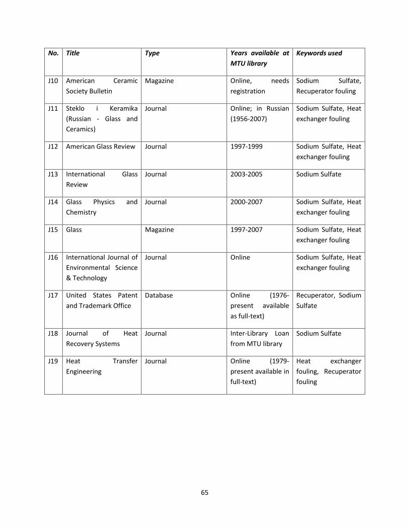
@#!!
K$;# L*)-.# LM&.# N.'(1# 'O'*-'P-.# ')#QLR#-*P('(M#
@.MS$(21#,1.2#
I"$! YV*.(K&)! T*.&V(K!+0K(*4W!L1==*4()!
6&2&i()*! Q)=()*5! )**,U!.*2(U4.&4(0)!
+0,(1V! +1=R&4*5!%*K1S*.&40.!R01=()2!
I""! +4*M=0! (! [*.&V(M&!?%1UU(&)! D! a=&UU! &),!T*.&V(KUA!
I01.)&=! Q)=()*v! ()! %1UU(&)!?":#@DC$$GA!
+0,(1V! +1=R&4*5! /*&4!*FK3&)2*.!R01=()2!
I"C! YV*.(K&)!a=&UU!%*'(*`! I01.)&=! "::GD":::! +0,(1V! +1=R&4*5! /*&4!*FK3&)2*.!R01=()2!
I";! 7)4*.)&4(0)&=! a=&UU!%*'(*`!
I01.)&=! C$$;DC$$#! +0,(1V!+1=R&4*!
I"9! a=&UU! N3WU(KU! &),!T3*V(U4.W!
I01.)&=! C$$$DC$$G! +0,(1V! +1=R&4*5! /*&4!*FK3&)2*.!R01=()2!
I"#! a=&UU! 6&2&i()*! "::GDC$$G! +0,(1V! +1=R&4*5! /*&4!*FK3&)2*.!R01=()2!
I"@! 7)4*.)&4(0)&=! I01.)&=!0R!X)'(.0)V*)4&=! +K(*)K*!H!<*K3)0=02W!
I01.)&=! Q)=()*! +0,(1V! +1=R&4*5! /*&4!*FK3&)2*.!R01=()2!
I"G! e)(4*,! +4&4*U! N&4*)4!&),!<.&,*V&.M!QRR(K*!
-&4&\&U*! Q)=()*! ?":G@DS.*U*)4! &'&(=&\=*!&U!R1==D4*F4A!
%*K1S*.&40.5! +0,(1V!+1=R&4*!
I"B! I01.)&=! 0R! /*&4!%*K0'*.W!+WU4*VU!
I01.)&=! 7)4*.D_(\.&.W! _0&)!R.0V!6<e!=(\.&.W!
+0,(1V!+1=R&4*!
I":! /*&4! <.&)UR*.!X)2()**.()2!
I01.)&=! Q)=()*! ?":G:DS.*U*)4!&'&(=&\=*!()!R1==D4*F4A!
/*&4! *FK3&)2*.!R01=()25! %*K1S*.&40.!R01=()2!
!

@@!!
0)4)'I'N/&$'":'0""2&'_'51=%+&'[Y=,1$%,'81&$'"#'\4V((V4\\`^'!
K$;## L*)-.#'E2#T.1+(*&)*$E# LM&.# U*"E*%*+'E+.#.8P9HM!G]!/!VG!/1<!/! @! HGS<! /1@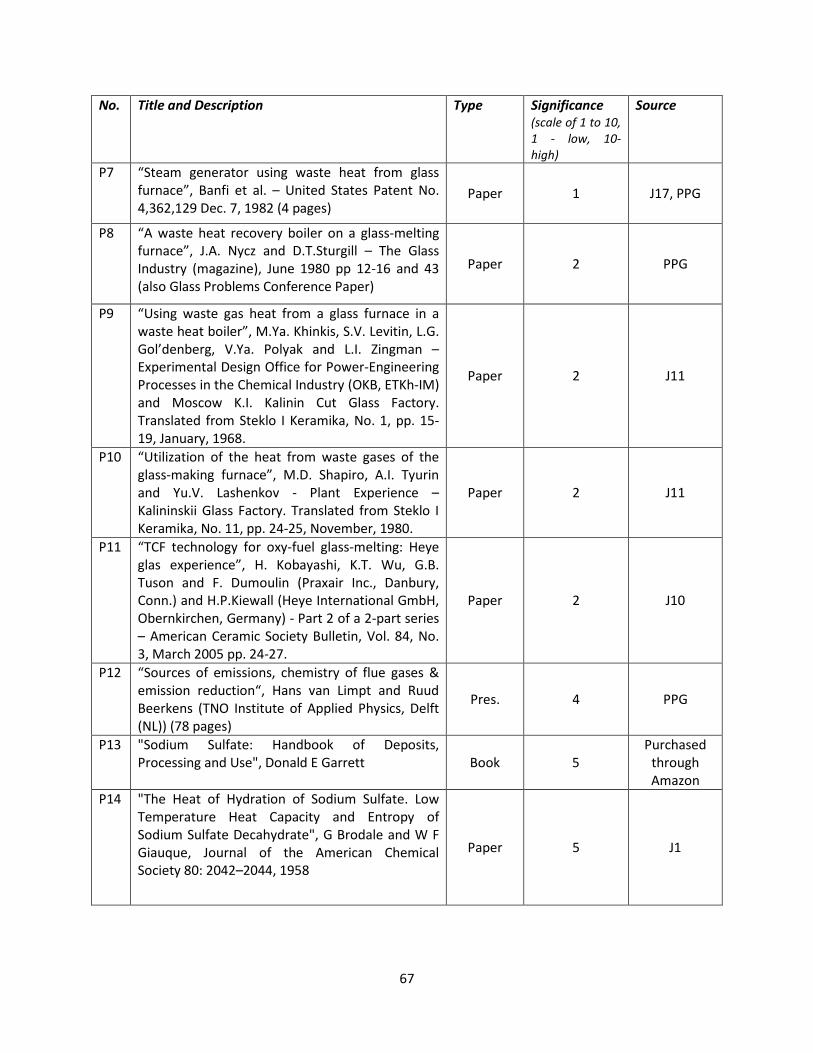
@G!!
K$;## L*)-.#'E2#T.1+(*&)*$E# LM&.# U*"E*%*+'E+.#.8P9HM!G]!/!VG!/1<!/! @! HGS<! /1@
@B!!
K$;## L*)-.#'E2#T.1+(*&)*$E# LM&.# U*"E*%*+'E+.#.8P9HM!G]!/!VG!/1<!/! @! HGS<! /1@
@:!!
K$;## L*)-.#'E2#T.1+(*&)*$E# LM&.# U*"E*%*+'E+.#.8P9HM!G]!/!VG!/1<!/! @! HGS<! /1@
G$!!
I==%#,/K' !T' I,,/$/"#18' C/3-+%&' 1#,' A1O8%&' !"#$1/#/#3' 5+"=%+$/%&' ":'>",/-?'>-8:1$%'Q%="&/$'
:%+;#'8<0'b%"-4*)'!"4$#".-#)'4A'?4&-*,'?*;A%.#'X-(#"%;)'C<D'
!
!
!
:%+;#'8E0'84,$4)-.-4('4A'H%).#'B%)'A"4,'%'A;%.@B;%))'A*"(%9#'C<VD'
9$4&$E.E)# V$-,4.#W#
/CQ! ";J;!
TQC! BJ@!
QC! #JC!
ZC! GCJG!
+QC! "J@!F!"$DC!
<04&=!Z&!?&U!Z&Q/A! BJ;!F!"$D;!
<04&=!T=!?&U!/T=A! 9J$!F!"$D;!
!
!
!

G"!!
:%+;#'8L0'T;*#'B%)'94,$4)-.-4()'A4"'#a$#"-,#(.)'-('d#A#"#(9#'C<_D'
?$#9-#'c%)'(*,+#"'
J# JJ# JJJ# JV# V# VJ#
6&O0.!US*K(*U!8!.C!^GH%2!!KI! 9J#! 9J#! 9J#! CJ$! 9J#! 9J#!GI! GCJG! GCJG! GCJG! GCJC! GCJG! GCJG!æIK! ";J$! ";J$! ";J$! "#J$! ";J$! ";J$!�KI! :J$! :J$! :J$! "$J$! :J$! :J$!ç¤! $JB! $JB! $JB! $JB! $JB! $JB!
-0S&)4U!8!.FF$2!GH! "C#! @@! @@! D! D! D!è! D! D! D! @$! D! D!�H! D! D! ;;! D! D! D!éê! D! ;;! D! D! D! D!£ë! D! D! D! D! 9$! 9$!ì! D! D! D! :@! D! D!J! C9$! CG! CG! "#$! D! ;$!�í! @CJ#! @@! @@! D! D! D!î! D! D! D! @$! D! D!
!
!
! '

GC!!
:%+;#'8V0'?4,#'95#,-9%;'9;#%(-(B'%B#(.)'G"#$"4&*9#&'A"4,'C<MDJ'
T4*;%(.' 85#,-9%;'9;#%(-(B'%B#(.' 84,,#(.)'
7.0)!0F(,*U!7)3(\(4*,! 3W,.0R=10.(K5!3W,.0K3=0.(K5! K(4.(K! 0.! U1=S3&V(K!&K(,5!X-<Y!
7)3(\(4*,! 3W,.0R=10.(K! &K(,! (U! \W!R&.! 43*!V0U4!*RR*K4('*!&2*)4!\14!K&))04! \*! 1U*,! (R! ,*S0U(4U!K0)4&()! V0.*! 43&)! "j! S#^!K&=K(1V!
T&=K(1V!0.!6&2)*U(1V!UK&=*!7)3(\(4*,! /W,.0K3=0.(K! &K(,5!X-<Y!
YU!R0.!(.0)!0F(,*U!
Q(=U!0.!=(234!2.*&U*U!
?&A +0,(1V! 3W,.0F(,*5!K&.\0)&4*! 0.! 4.(DU0,(1V!S30US3&4*! `(43! 0.! `(43014!,*4*.2*)4U!0.!
?\A +0='*)4! 8! `&4*.!*V1=U(0)U5! *J2J! M*.0U*)*! D!`&4*.!
Y=M&=(U! &.*! &=U0! 1U*,! R0.! 43*!.*V0'&=!0R!\(0=02(K&=!,*S0U(4U!
!
eU*R1=! R0.! )0)DR*..01U! UWU4*VU!`3(K3!V&W!\*!&44&KM*,!\W!&=M&=(U!
/*&'W!0.2&)(K!,*S0U(4U5!*J2J!4&.U5!S0=WV*.U!
T3=0.()&4*,!0.!&.0V&4(K!U0='*)4U!R0==0`*,!\W!O*4!`&U3()2!
<.(K3=0.0*43W=*)*! &),!S*.K3=0.0*43W=*)*! &.*! )0)DR=&VV&\=*!
T0M*dK&.\0)!Y=M&=()*! U0=14(0)U! 0R! S04&UU(1V!S*.V&)2&)&4*! 0.! U4*&Vd&(.!,*K0M()2!
+4*&Vd&(.! ,*K0M()2! (U! 1U*,! 0)!R1.)&K*! 41\*U! `3*.*! K0M*! (U!.*V0'*,!\W!K0)4.0==*,!\1.)()2!

G;!!
I==%#,/K' QT' 51+1?%$+/.' DU-1$/"#&' Q%?"#&$+1$/#3' !;1#3%' /#' E%1$'A+1#&:%+'<1$%&'$"'$;%'E%1$'5/=%',-%'$"'J14>9G'51+$/.-81$%'C"+?1$/"#'!
/*.*5!43*!V*&)!2&U!4*VS*.&41.*!v�!(U!&UU1V*,!&U!511*+!>!30-%/)!&J!
!1&%'*'L'E%1$'=/=%'&-+:1.%'/&'.8%1#'[#"',%="&/$^'!
E.0V!&(.!S.0S*.4(*U!4&\=*!()!%*R*.*)K*!]@^5!&4!v� T 600¥5!
!º! }!:GJ:B@!F!"$D@!VCdU5!DDDDDDDDDDDDDDDDDDDDDDDDDDDDDDDDDDDDDDDDDDDDDDDDDDDDDDDDDDDDDDDDDDDDDDDDDDDDDDDDDDDDDDDDDDDDDD?-"A!��! }!$JG"B"5!DDDDDDDDDDDDDDDDDDDDDDDDDDDDDDDDDDDDDDDDDDDDDDDDDDDDDDDDDDDDDDDDDDDDDDDDDDDDDDDDDDDDDDDDDDDDDDDDDDDDDDDDDDDDD?-CA!��g! } ��Yvg^5!DDDDDDDDDDDDDDDDDDDDDDDDDDDDDDDDDDDDDDDDDDDDDDDDDDDDDDDDDDDDDDDDDDDDDDDDDDDDDDDDDDDDDDDDDDDDDDDDDDDDDDDDDDDDD?-;A!�! }!@$JG!F!"$D;!PdVJ[!DDDDDDDDDDDDDDDDDDDDDDDDDDDDDDDDDDDDDDDDDDDDDDDDDDDDDDDDDDDDDDDDDDDDDDDDDDDDDDDDDDDDDDDDDDDDDDD?-9A!
!
E0.!U0='()2!Xc1&4(0)!?"CA5!`*!&=U0!)**,!40!M)0`!%*W)0=,gU!)1V\*.!c�[!&4!_v T v�bJ!!c�[ T z[ï !DDDDDDDDDDDDDDDDDDDDDDDDDDDDDDDDDDDDDDDDDDDDDDDDDDDDDDDDDDDDDDDDDDDDDDDDDDDDDDDDDDDDDDDDDDDDDDDDDDDDDDDDDDDDDDDDDDDDDDD?-#A!ð! }!#!R4dU5!?()R0.V&4(0)!U1SS=(*,!\W!NNaA!DDDDDDDDDDDDDDDDDDDDDDDDDDDDDDDDDDDDDDDDDDDDDDDDDDDDDDDDDDDDDDDDDDDDDDD?-@A!�!! }!;J#!()K3!?()R0.V&4(0)!U1SS=(*,!\W!NNaA!DDDDDDDDDDDDDDDDDDDDDDDDDDDDDDDDDDDDDDDDDDDDDDDDDDDDDDDDDDDDDDDDDDDD?-GA!
+05!c�[! }!?#J$!F!$J;$9BA!F!?;J#!F!$J$C#9A!d!?:GJ:B@!F!"$D@A!
! }!<M_E2U'DDDDDDDDDDDDDDDDDDDDDDDDDDDDDDDDDDDDDDDDDDDDDDDDDDDDDDDDDDDDDDDDDDDDDDDDDDDDDDDDDDDDDDDDDDDDDDDDDDDDDDDDDDDDDD?-BA!
!
E.0V!<&\=*!B!()!%*R*.*)K*!]@^5!�! }!$JC@5!&),!DDDDDDDDDDDDDDDDDDDDDDDDDDDDDDDDDDDDDDDDDDDDDDDDDDDDDDDDDDDDDDDDDDDDDDDDDDDDDDDDDDDDDDDDDDDDDDDDDDDDDDDDDDD?-:A!R!! }!$J@!DDDDDDDDDDDDDDDDDDDDDDDDDDDDDDDDDDDDDDDDDDDDDDDDDDDDDDDDDDDDDDDDDDDDDDDDDDDDDDDDDDDDDDDDDDDDDDDDDDDDDDDDDDDDDDDDD?-"$A!
G9!!
R0.!"$$$!~!%*-!~!C!F!"$#!
&),!�! }!$J;G!R0.!N.!¶!"$!DDDDDDDDDDDDDDDDDDDDDDDDDDDDDDDDDDDDDDDDDDDDDDDDDDDDDDDDDDDDDDDDDDDDDDDDDDDDDDDDDDDDDDDDDDDDDDDD?-""A!
+0='()2!Xc1&4(0)!?"CA5!������[! }!?$JC@A?";BCJGA$J@?$JG"B"A$J;G?$JG"B"dN.UA$JC#!
! }!"@JCCGCd_O8$JC#!DDDDDDDDDDDDDDDDDDDDDDDDDDDDDDDDDDDDDDDDDDDDDDDDDDDDDDDDDDDDDDDDDDDDDDDDDDDDDDDDDDDDDDDDDDDDDDDDDD?-"CA!
E.0V!Xc1&4(0)!?";A5!o� T ������[ Ã[! }!"@JCCGCd_O8$JC#!F!??@$JG!F!"$D;Ad?;J#!F!$J$C#9AA!
! ! }!""J$G:BdN.U$JC#!PdVCJ[!DDDDDDDDDDDDDDDDDDDDDDDDDDDDDDDDDDDDDDDDDDDDDDDDDDDDDDDDDDDDDDDDDDDDDDDDDDDD?-";A!Ug T ñ[ò� k 2 d̀qr�! !
}!?;J"9"#:!F!?;J#!F!$J$C#9A!F!?:J;!F!$J;$9BAdCA!m!?C!F!?;!F!$J$C#9A!F!?:J;!F!$J;$9BAA!
! }!"JCC;G!VC!DDDDDDDDDDDDDDDDDDDDDDDDDDDDDDDDDDDDDDDDDDDDDDDDDDDDDDDDDDDDDDDDDDDDDDDDDDDDDDDDDDDDDDDDDDDDDDDDDDDDDDDD?-"9A!
+0='()2!Xc1&4(0)!?""A5!ifysrz T o�Ug_v� \ vgb!}!""J$G:BdN.U
$JC#!F!"JCC;G!F!?BG;J"#!D!Z8A!DDDDDDDDDDDDDDDDDDDDDDDDDDDDDDDDDDDDDDDDDDDDDDDDDDDDDDDDDDDDDDDDDDD?-"#A!
+()K*!Xc1&4(0)! ?-"#A! (U!)0`!*FS.*UU*,!&U!&! R1)K4(0)!0R!Z8!0)=W5! K0)'*K4(0)!3*&4! 4.&)UR*.! .&4*U!K&)!\*!S=044*,!'*.U1U!U1.R&K*!4*VS*.&41.*U5!&U!U30`)!()!E(21.*!-"J!
E.0V!Xc1&4(0)!?@A5!ifwxV T Ug�dg��g_vd� \ vg�b!!/*.*5!Ug! }!"JCC;G!VC!DDDDDDDDDDDDDDDDDDDDDDDDDDDDDDDDDDDDDDDDDDDDDDDDDDDDDDDDDDDDDDDDDDDDDDDDDDDDDDDDDDDDDDDDDDDDDDDDDDDDDDDD?-"@A!�dg! }!$J$C;@!?R.0V!K&=K1=&4(0)U!&U!U30`)!\W!Xc1&4(0)!?GA!&),!1U()2!43*!U(VS=(R(*,!K0)R(21.&4(0)!&U!
U30`)!()!E(21.*!GA5!DDDDDDDDDDDDDDDDDDDDDDDDDDDDDDDDDDDDDDDDDDDDDDDDDDDDDDDDDDDDDDDDDDDDDDDDDDDDDDDDDDDDDDDDDDDDDDDDDDDDDDDDD?-"GA!�! }!#J@G!F!"$DB!PdVCJ[95!DDDDDDDDDDDDDDDDDDDDDDDDDDDDDDDDDDDDDDDDDDDDDDDDDDDDDDDDDDDDDDDDDDDDDDDDDDDDDDDDDDDDDDDDDDD?-"BA!�g! }!'&.(&\=*5!DDDDDDDDDDDDDDDDDDDDDDDDDDDDDDDDDDDDDDDDDDDDDDDDDDDDDDDDDDDDDDDDDDDDDDDDDDDDDDDDDDDDDDDDDDDDDDDDDDDDDDDDDD?-":A!vd! }!"#$$lT!}!"GG;J"#
G#!!
+0='()2!Xc1&4(0)!?@A5!ifwxV! }!"JCC;G!F!$J$C;@!F!?#J@G!F!"$DBA!F!�g!F!?"GG;J"#9!8!vg�A!DDDDDDDDDDDDDDDDDDDDDDDDDDDDDDDDDDDDDDDDDDDDDDDD?-C"A!E(21.*! -"! U30`U! S=04U! 0R! ifysrzYvg^! &),! ifwxVY�g,vg^! '*.U1U! vg5! R0.! '&.(01U! '&=1*U! 0R! �g! Y�g T1, 0.9, 0.5, 0.1 �Q 0.01^J!<3*!)*2&4('*!'&=1*!0R!ifysrz!&4!vg T 700¥!(),(K&4*U!43&4!`3*)!v� � vg5!3*&4!(U!K0)'*K4*,!&`&W!R.0V!43*!3*&4!S(S*J!
!
T-B*"#'1<0'6#%.'."%()A#"'"%.#)'S-%'94(S#9.-4('%(&'"%&-%.-4('A4"'S%"-4*)'S%;*#)'4A')*"A%9#'%+)4"$.-S-./'GX1J'S#")*)')*"A%9#'.#,$#"%.*"#)'GL1J'C?-(9#'L1'i'L"K'94(S#9.-4('5#%.'."%()A#"'-)'(#B%.-S#2D'
!
!
!1&%'**'L'J14>9G',%="&/$'":'$;/.2#%&&'_MNOPb'/&':"+?%,'"#'$;%';%1$'=/=%'&-+:1.%'!
7)!0.,*.!40!K&=K1=&4*!43*!K3&)2*!()!K0)'*K4(0)!3*&4!4.&)UR*.!.&4*5!`*!K&)!V&M*!1U*!0R!Xc1&4(0)U!?"@A!&),!?"GAJ!E.0V!43*U*!C!*c1&4(0)U5!o� T �]ÅÆÇÈ!DDDDDDDDDDDDDDDDDDDDDDDDDDDDDDDDDDDDDDDDDDDDDDDDDDDDDDDDDDDDDDDDDDDDDDDDDDDDDDDDDDDDDDDDDDDDDDDDDDDDDDDDDDDDDDD?-CCA!+05!K0)'*K4(0)!43*.V&=!.*U(U4&)K*!`3*)!43*!3*&4!S(S*!(U!K=*&)!K&)!\*!R01),!014!R.0V!Xc1&4(0)!?-";A!&U>!
D9$$$
DC$$$
$
C$$$
9$$$
@$$$
B$$$
"$$$$
"C$$$
"9$$$
"@$$$
"B$$$
$ "$$ C$$ ;$$ 9$$ #$$ @$$ G$$ B$$
6#%.'."%()A#"'"%.#'GF
J
?*"A%9#'.#,$#"%.*"#'4A'5#%.'$-$#'GY8J
��,04�K0)' ��,04�.&,?&=S3&}"A
��,04�.&,?&=S3&}$J:A ��,04�.&,?&=S3&}$J#A
��,04�.&,?&=S3&}$J"A ��,04�.&,?&=S3&}$J$"A

G@!!
cysrzY�^ T �¿É T ówôõ.mö��.÷²¯±!DDDDDDDDDDDDDDDDDDDDDDDDDDDDDDDDDDDDDDDDDDDDDDDDDDDDDDDDDDDDDDDDDDDDDDDDDDDDDDDDDDDDDDDDDDDDDDDDDDDDDDD?-C;A!Z0`5!43*!&,,(4(0)&=!43*.V&=!.*U(U4&)K*!,1*!40!43*!S&.4(K1=&4*!=&W*.!K&)!\*!&,,*,!0)!40!43*!.(234D3&),!U(,*!0R!?-C;A!40!2*4!43*!)*`!K0)'*K4(0)!43*.V&=!.*U(U4&)K*!&U>!cysrzY�^ T cysrzY�^ k ÁøùúÃøùú !DDDDDDDDDDDDDDDDDDDDDDDDDDDDDDDDDDDDDDDDDDDDDDDDDDDDDDDDDDDDDDDDDDDDDDDDDDDDDDDDDDDDDDDDDDDDDDDDDDDD?-C9A!E.0V!Xc1&4(0)U!?"$A!&),!?-C9A5!43*!K0)'*K4(0)!3*&4!4.&)UR*.!.&4*!K&)!)0`!\*!K&=K1=&4*,!&U>!ifysrzÝ T �]ÅÆÇÈYm^ Ug_v� \ vgÝb T �]ÅÆÇÈYÂ^ Äûøùúüøùú Ug_v� \ vgÝb!DDDDDDDDDDDDDDDDDDDDDDDDDDDDDDDDDDDDDDDDDDDDDDDDDDDDDDDDDDD?-C#A!Z04*! 43&4!vgÝ ã vg! &),!&=U0!�VWX! (U!&=U0!&! R1)K4(0)!0R!vgJ! <3*!K3&)2*! ()!K0)'*K4(0)!3*&4! 4.&)UR*.! .&4*!�∆ifysrz T if ysrzÝ \ ifysrz�!(U!&!R1)K4(0)!0R!`VWX!5!�VWX!5!vg!&),!vgÝ!R0.!&!2('*)!'&=1*!0R!v�J!%&,(&4(0)!3*&4! 4.&)UR*.! .&4*! 40! 43*!UWU4*V!&=U0! K3&)2*U5!,1*! 40!ifwxV T ifwxVY�g,vg^J! Xc1&4(0)! ?-C"A!K&)!\*!1U*,!40!K&=K1=&4*!ifwxV!`(43!�g T �VWXJ!E.0V!Xc1&4(0)!?-C"A5!ifwxVÝ T Ug�dg��VWX_vd� \ vgÝ�b!DDDDDDDDDDDDDDDDDDDDDDDDDDDDDDDDDDDDDDDDDDDDDDDDDDDDDDDDDDDDDDDDDDDDDDDDDDDDDDDDDDDDDDDD?-C@A!E.0V!Xc1&4(0)U!?@A!&),!?-C@A5!∆ifwxV T ifwxVÝ \ ifwxV T Ug�dg�þ�g_vd� \ vgÝ�b \ �VWX_vd� \ vg�bÿ!DDDDDDDDDDDDDDDDDDDDDDDDDDDDDDDDDDDDDDDD?-CGA!E.0V!Xc1&4(0)!?-CGA5!43*!(VS0.4&)4!'&.(&\=*U!43&4!,*4*.V()*!∆ifwxV!&.*!�g!5!�VWX!5!vg!&),!vgÝ5!R0.!&!2('*)!'&=1*!0R!vd!&),!&!2('*)!U*41S5!&U!.*S.*U*)4*,!()!E(21.*!@J!Y=U05!R.0V!Xc1&4(0)!?@A5!43*!.&,(&4(0)!43*.V&=!.*U(U4&)K*U!`3*)!43*!3*&4!S(S*!(U!fK=*&)g!&),!`3*)!43*.*!(U!&!Z&C+Q9!,*S0U(4!=&W*.!&.*>!cwxV T �¿!"ø T �#$ô%&ô�'$mÄ'ôm�_'$Ä'ôb!DDDDDDDDDDDDDDDDDDDDDDDDDDDDDDDDDDDDDDDDDDDDDDDDDDDDDDDDDDDDDDDDDDDDDDDDDDDDDDDDDDD?-CBA!&),!cwxVÝ T �¿!"ø( T �#$ô%&øùú�'$mÄ'ô(m�_'$Ä'ô(b!DDDDDDDDDDDDDDDDDDDDDDDDDDDDDDDDDDDDDDDDDDDDDDDDDDDDDDDDDDDDDDDDDDDDDDDDDDDDDDD?-C:A!

GG!!
I==%#,/K'DT'<%&="#&%&'$"'D#U-/+@'N%$$%+'[/#'I==%#,/K'I^':+"?'5"$%#$/18'>-==8/%+&'":'E%1$'DK.;1#3%+'C"-8/#3'!"#$+"8'DU-/=?%#$'
DDDDDDDDDDDDDDDDDDDDDDDDDDDDDDDDDDDDDDDDDDDDDDDDDDDDDDDDDDDDDDDDDDDDDDDDDDDDDDDDDDDDDDDDDDDDDDDDDDDDDDDDDDDDDDDDDDDDDDDDDDDDDDDDDDDDDDDDDD!
Gentlemen Tube Tech International Ltd posses every tube / pipeline cleaning method available worldwide. That is, we are aware of every conceivable alternative that you will have knowledge of and its limitations. This should save you re-inventing the wheel. We have over 12 solutions to clean this tube that will be robust and cost effective. If you wish me to list all the alternatives I am happy to do so or even discuss via tel conference. (try 1600 uk time Monday afternoon ) To this end I recommend the Rotaflex. Graham will provide a proposal if you wish once you have completed a Tube Tech questionnaire Kind regards Mike Mike Watson Technical Director Tube Tech International Ltd "Failure is not an option" www.tubetech.com
DDDDDDDDDDDDDDDDDDDDDDDDDDDDDDDDDDDDDDDDDDDDDDDDDDDDDDDDDDDDDDDDDDDDDDDDDDDDDDDDDDDDDDDDDDDDDDDDDDDDDDDDDDDDDDDDDDDDDDDDDDDDDDDDDDDDDDDDDD!
'