Automated High Resolution Measurement of Heliostat Slope Errors
1
Final Project Report:
Heliostat-Concentrator
Solar Cooker
Team Helios
Ian Davison and Devin Mast
December 3, 2015

2
Statement of Disclaimer Since this project is a result of a class assignment, it has been graded and accepted as fulfillment
of the course requirements. Acceptance does not imply technical accuracy or reliability. Any use
of information in this report is done at the risk of the user. These risks may include catastrophic
failure of the device or infringement of patent or copyright laws. California Polytechnic State
University at San Luis Obispo and its staff cannot be held liable for any use or misuse of the
project.

3
Table of Contents
Statement of Disclaimer ................................................................................................................ 2
Table of Contents ......................................................................................................................... 3
List of Tables ............................................................................................................................... 6
List of Figures .............................................................................................................................. 6
Nomenclature .............................................................................................................................. 8
EXECUTIVE SUMMARY ............................................................................................................ 9
1. Introduction ............................................................................................................................10
1.1 Solar Cooking Background ..................................................................................................10
1.2 Objectives..........................................................................................................................13
1.2.1 Optimize Concentration at a Stationary Point ...................................................................13
1.2.2 User-Friendliness .........................................................................................................14
1.2.3 Cost and Sustainability ..................................................................................................14
1.3 Requirements .....................................................................................................................14
1.3.1 User Parameters ...........................................................................................................15
1.3.2 Investment Considerations .............................................................................................15
1.3.3 Performance ................................................................................................................16
1.3.4 Safety .........................................................................................................................16
1.3.5 Maintenance and Sustainability ......................................................................................16
1.4 Year-Long Plan ..................................................................................................................17
1.4.1 Winter .........................................................................................................................17
1.4.2 Spring .........................................................................................................................17
1.4.3 Fall .............................................................................................................................17
2. Background .............................................................................................................................18
2.1 Existing Products ................................................................................................................18
2.2 Applicable Standards ..........................................................................................................18
3. Design Development ................................................................................................................19
3.1 Concept Generation ............................................................................................................19
3.2 Top Concepts .....................................................................................................................19
3.3 Selection Process ................................................................................................................23
3.4 Selection ...........................................................................................................................23
4. Proposed Design ......................................................................................................................25

4
4.1 Design Details ....................................................................................................................25
4.1.1 Reflector .....................................................................................................................25
4.1.2 Concentrator ................................................................................................................27
4.2 Material Selection and Production ........................................................................................29
4.2.1 Reflector .....................................................................................................................30
4.2.2 Concentrator ................................................................................................................30
4.3 Analysis Results .................................................................................................................30
4.3.1 Concentrator Size and Cooking Power ............................................................................30
4.3.2 Reflector Deflection and Efficiency ................................................................................30
4.3.3 Heliostat Construction and Out-Of-Plane Deflection .........................................................31
4.3.4 Reflector Construction and Torque Requirements .............................................................32
4.3.5 Reflector Weight and Deflection ....................................................................................32
4.4 Cost Analysis .....................................................................................................................32
4.5 Schematics .........................................................................................................................32
4.6 Safety Considerations ..........................................................................................................32
4.7 Maintenance and Repair ......................................................................................................33
5. Product Realization ..................................................................................................................34
5.1 Fall Construction ................................................................................................................34
5.2 Design Changes since the Critical Design Report ...................................................................34
5.2.1 Target Users ................................................................................................................34
5.2.2 Concentrator ................................................................................................................34
5.2.3 Seasonal Adjustment .....................................................................................................35
5.2.4 String Guide/tensioner ..................................................................................................36
5.2.5 Tracking Circuit and Power Source.................................................................................36
5.2.6 Top and Bottom Support ...............................................................................................37
5.2.7 Temporary Stand ..........................................................................................................38
5.3 Recommendations for Future Design Development .................................................................38
5.3.1 Insulation Possibilities ..................................................................................................38
5.3.2 Reflective Surface Coverings .........................................................................................38
5.3.3 Frame Alterations .........................................................................................................38
5.3.4 Concentrator ................................................................................................................39
5.3.5 Tracking System ..........................................................................................................39
6. Design Verification ..................................................................................................................40
5
6.1 Testing Procedures .............................................................................................................40
6.2.1 Daily Setup Time .........................................................................................................40
6.2.2 Maximum Input Force...................................................................................................40
6.2.3 Static Heat Spot ............................................................................................................41
6.2.4 Static Heat Spot, with Wind ...........................................................................................41
6.2.5 Performance ................................................................................................................41
6.2.6 Maintenance ................................................................................................................43
7. Conclusion ..............................................................................................................................44
Appendix A: References
Appendix B: Quality Function Deployment
Appendix C: Decision Matrices
Appendix D: Vendors and Pricing
Appendix E: Design Verification Plan
Appendix F: Testing Procedures
Appendix G: Detailed Analysis
Appendix H: Gantt Chart
Appendix I: Potential Failure Modes and Effects Analysis
Appendix J: Technical Drawings
Appendix K: Instructions

6
List of Tables Table 1. Solar cooker formal engineering requirements ............................................................................. 15
Table 2. Projected costs for heliostat system prototype .............................................................................. 32
Table 3. Tracking Circuit Component Specifications ................................................................................. 37
Table 4. Test names and associated specification numbers ........................................................................ 40
Table 5. Revised specifications for testing formal requirements ................................................................ 40
Table 6. System style decision matrix. ....................................................................................................... 47
Table 7. Daily tracking mechanism decision matrix. .................................................................................. 48
Table 8. Seasonal adjustment decision matrix. ........................................................................................... 48
List of Figures Figure 1. A woman in Totolgalpa uses a solar box cooker to produce baked goods for sale. [2] .............. 11
Figure 2. An Indian woman and her family outside their home with a parabolic concentrator (A)
[3]. A Scheffler reflector at the Barli Development Institute in Indore (B) [3]. ............................ 12
Figure 3. Diagram and explanation of parabolic concentration for solar cooking purposes [7] ................. 12
Figure 4. Panel cookers made from corrugated plastic with a reflective coating being used in
India. [2] ......................................................................................................................................... 13
Figure 5. Small scale models used to facilitate understanding of how to concentrate sunlight.
Models were built with wooden skewers, scrap Mylar, and foam core. ........................................ 19
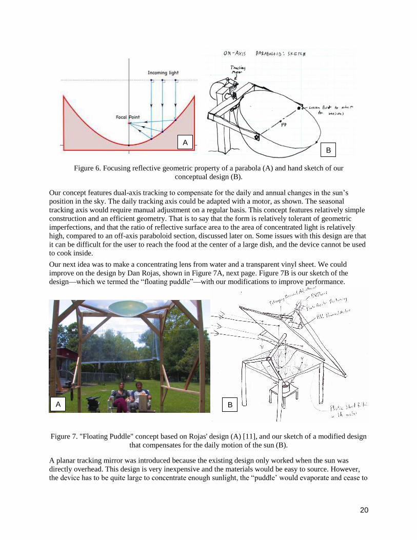
Figure 6. Focusing reflective geometric property of a parabola (A) and hand sketch of our
conceptual design (B). ................................................................................................................... 20
Figure 7. "Floating Puddle" concept based on Rojas' design (A) [11], and our sketch of a modified
design that compensates for the daily motion of the sun (B). ........................................................ 20
Figure 8. Conceptual diagram of a Scheffler dish, which has a focal point that remains fixed
relative to the ground. .................................................................................................................... 21
Figure 9. Sketch of Fresnel lens concentrator concept showing relative positions and tracking
device. ............................................................................................................................................ 21
Figure 10. Concept sketches for a dual-mirror system layout (A) and a potential seasonal
compensation system design (B). .................................................................................................. 22
Figure 11. Parabolic trough concept, where a high-temperature fluid carries heat to the cooking
interface. ........................................................................................................................................ 22
Figure 12. A 3D rendering of the primary reflector .................................................................................... 25
Figure 13. A 3D layout of the overall system ............................................................................................. 26
Figure 14. Conceptual (A) and revised (B) design of seasonal adjustment for the primary reflector ........ 27
Figure 15. Parabolic profile sweep setup with finished mold surface. When revolved about the
axis, the pattern lightly contacts the light brown concrete-like mixture evenly. ........................... 28
Figure 16. Wooden lath frame, weighted down by bricks after pressing dirt and plastic were
removed. The bricks were necessary because the elasticity of the wood caused the frame
to separate slightly from the mold. ................................................................................................ 28
Figure 17. Completed prototype with Mylar strips adhered to wooden frame. .......................................... 29
Figure 18. Solidworks ray tracing sketch, assuming ideal concentrator and circular reflector.
Dimensions in meters. .................................................................................................................... 31
Figure 19. Close up of the new seasonal adjustment support rod design.................................................... 35

7
Figure 20. String tensionr system. Used to eliminate slack in the daily tracking system as the
geometry of the string drive changes with the rotation of the heliostat. ........................................ 36
Figure 21. Tracking circuit: used to detect movement of the sun and actuate the motor to orient
the heliostat. ................................................................................................................................... 37
Figure 22. Plot of temperature as a function of time demonstrating how the solar cooker heated up
2 kilograms of water. ..................................................................................................................... 42
Figure 23. Instantaneous power absorbed at the hot spot with varying time steps. .................................... 43

8
Nomenclature
Heat flux The time rate of heat transfer per unit area
Heliostat A device including a reflective surface that turns so as to keep reflecting sunlight toward a
target
Insolation The cumulative solar energy per unit area over a defined period of time
Irradiation The instantaneous incident (solar) radiative power per unit area
Lath A thin flat strip of wood
Paraboloid The solid generated by revolving a parabola about its axis
Off-axis
paraboloid
The section of a paraboloid defined by a plane not parallel to its axis
Scheffler dish A flexible off-axis paraboloid solar concentrator invented by Wolfgang Scheffler
Solar azimuth
angle
The angle between a projection of the vector from an observer on Earth to the sun on a
horizontal reference plane and due north
Solar elevation
angle
The angle between a horizontal reference plane and the vector from an observer on Earth to
the sun
Solar zenith
angle
The angle between the vertical and the vector from an observer on Earth to the sun; the
complement of the elevation angle

9
EXECUTIVE SUMMARY This document is the full report for the senior project of Cal Poly Mechanical Engineering students Ian
Davison and Devin Mast. The report encompasses the full project process, including background
research, identification of need, design requirements, design development, proposed design, design
realization, changes to proposed design, and design verification. We were tasked with the design and
manufacture of a “dual mirror” solar cooker to verify a concept for a new type of off-axis parabolic solar
cooker conceived by Dr. Pete Schwartz, the sponsor of the senior project and a physics professor at Cal
Poly. Previously, off-axis parabolic solar cookers have used a deformable concentrator to adjust for
seasonal change in solar position. The core innovation of the dual mirror concept was to replace the
deformable concentrator with a rigid dish and use a tracking heliostat to adjust for seasonal variation,
redirect the light, and provide a constant light source on the dish. The motivation for this modification is
to simplify construction and lower costs, as deformable dishes must maintain precise geometry
throughout deformation and are therefore difficult to manufacture. This means traditional off-axis
parabolic solar cookers are often beyond the financial reach of the intended users: economically
disadvantaged communities in developing countries. The scope of the project initially encompassed the
creation of both the concentrator and the heliostat but was redefined at the beginning of fall quarter to
solely encompass the tracking heliostat, as proof of concept could be accomplished using a previously
built concentrator. The heliostat was completed and testing was performed fall quarter.

10
1. Introduction
This report was compiled by Team Helios of the California Polytechnic State University (Cal Poly) in
San Luis Obispo, California. It represents the cumulative efforts of team members Ian Davison and Devin
Mast, senior Mechanical Engineering students, on the behalf of their sponsor Dr. Pete Schwartz. Team
Helios was under the advisement of Professor Eileen Rossman of the Cal Poly Mechanical Engineering
Department.
The team was tasked with developing a solar cooker. The cooker will better meet the needs of members
of developing communities in Yemen1 by offering power comparable to current state-of-the-art products
while being more affordable, reliable, easy to use, and serviceable on site. It should outperform the
previous Scheffler heliostat built by Cal Poly students and be competitive with other solar cookers on the
market. For the purposes of this project, we have focused our efforts on the design and construction of the
heliostat frame, tracking system, and concentrating dish2 of a solar cooking system. Future projects may
investigate integration into living structures, cooktop design, and insulation of cookware. In the long
term, this project will facilitate the development of a solar cooking system that will improve the quality of
life in developing communities worldwide.
1.1 Solar Cooking Background
In developing countries there is a need for a low-cost means of cooking food. Many regions burn fuels to
create the heat needed to boil water and bake, but there are several problems associated with fuel-burning
cooking. In fuel-scarce regions, cooking consumes valuable organic resources, which degrades the local
environment and can sometimes lead to aggravated competition for these resources [1]. Some regions are
so scarce in fuel that it is too time-consuming and/or dangerous to collect [1]. Cooking with fire also leads
to soot-contaminated air, food, and water, which is harmful to health [1]. People in developing
communities with such limited resources cannot afford alternate fuels like natural gas. These factors
contribute to the need for an alternative source of energy for cooking.
With the help of various organizations, communities in India, Egypt, Ecuador, Nepal, and many other
countries have turned to solar energy as an alternative because it has several advantages over fuel-fed
fires. Irradiation at the Earth’s surface is roughly 1,000 W/m2, or 1 kW/m2. By focusing this radiation to a
more concentrated area, temperatures suitable for cooking can be reached. Since solar cookers require
only sunlight, there is no need to gather or burn fuels. The result is better air quality, less time spent
foraging for fuel, and less damage to the local environment [1]. A solar cooker is a one-time investment
that produces free, clean heat as long as there is sunlight.
Some communities are not turning to solar cooking, however. Some of the impediments to the transition
include the need for a different cooking space. This can either be a separate outdoor space, or integrated
into an existing home, but either way switching to solar cooking requires the construction of new or
different infrastructure. Solar cookers also consumer a fair amount of space, since the power output is
directly correlated to the area of sunlight collected by the dish. It is difficult to implement a solar cooker
in communities with tight space constraints. Another issue is the reliability of a solar cooker, which is
1 The project was originally associated with an interested NGO in Yemen, but that changed in May 2015. See
Section 5.2.1 Target Users. 2 The focus of the project with regard to the concentrating dish shifted in fall of 2015. Refer to Section 5.2.2
Concentrator.

11
only effective when the sun is strong. One work-around involves thermal energy storage systems, but that
comes at an added cost with additional losses.
Currently there are a number of solar cookers on the market that have been implemented in developing
communities. The simplest of these is a heat-trap box style cooker; an example is shown in Figure 1.
Solar box cookers are inexpensive and easy to manufacture. They “cook at moderate to high temperatures
and often accommodate multiple pots. Worldwide, they are the most widespread” [3, 4]. They do not
cook as fast as a fire.
Curved concentrator cookers are expensive and require trained skilled workers and specialty equipment to
produce. Additionally, they need to be adjusted regularly so they face the sun properly throughout the day
and year. These costs are offset by their cooking power, because they concentrate sunlight from a larger
area more accurately, resulting in higher heat and faster cooking times. They are especially suited to large
community cooking operations [4].
There are two main types of curved (parabolic) mirrors: on-axis and off-axis. Examples of each of these
are shown in Figure 2, next page. The more common design is the on-axis parabolic mirror, which is a
rigid mirror in the shape of the bottom of a paraboloid. These concentrators either have control systems
that use two axes to account for daily rotation and seasonal change or are manually pointed at the sun at
the time of use [5]. The second type of mirror is called a Scheffler Reflector, which is an off-axis
parabolic mirror. This design requires daily rotation and seasonal deformation of the dish to concentrate
sunlight on a fixed focus throughout the year [6, 8]. Figure 3 on the next page is a schematic showing
how the geometry of an off-axis parabolic mirror focuses sunlight.
Figure 1. A woman in Totolgalpa uses a solar box cooker
to produce baked goods for sale. [2]

12
There is also a hybrid of these two types, called a panel cooker, which combines the principle of
concentrating sunlight using the geometry of a paraboloid with the simple, planar construction of a box
cooker. They are inexpensive and fairly easy to make, which has made them popular. Figure 4, next page,
shows a common panel cooker.
Currently, there are a number of ways that researchers test solar concentrators. This variation in testing
methods is a result of differing objectives of solar cookers. Some focus on being cheap as possible or on
minimizing user input, while other try to maximize power supplied to cooking surface. One example of
testing protocol is the WBT (Water Boiling Test): “a laboratory test that evaluates stove performance
A B
Figure 3. Diagram and explanation of parabolic
concentration for solar cooking purposes [7]
Figure 2. An Indian woman and her family outside their home with a parabolic concentrator (A)
[3]. A Scheffler reflector at the Barli Development Institute in Indore (B) [3].

13
while [boiling or simmering water] in a controlled environment to investigate the heat transfer and
combustion efficiency of the stove.” [10]. A similar test is the CCT (Controlled Cooking Test). This
method attempts to evaluate the performance of designs in real life settings in comparison to traditional
methods of consumable fuel stoves. We plan to perform multiple tests incorporating these techniques
when we have completed our project.
1.2 Objectives
Ultimately we aimed to optimize the concentration of sunlight at a single stationary “point” for the
purpose of cooking. The end users will be members of communities in rural areas of developing nations,
so an additional objective is to maximize user-friendliness and minimize cost. Further, primary purposes
of choosing solar power to begin with include low operating cost and sustainability, so the solution should
also be designed and built with this sustainable manufacture and materials in mind. Before the product is
implemented in developing communities overseas, we wish to verify the design here in San Luis Obispo,
CA, so the product is tailored to this location. Finally, from the project management perspective, it is our
objective to deliver a finished, working solar concentrator that accomplishes these objectives in December
2015.
To link these objectives to engineering specifications, we employed a Quality Function Deployment
(QFD) diagram. The QFD diagram is a tool that systematically incorporates the needs of each customer
and engineering requirements to meet these needs. It also facilitates comparisons with existing
competitive designs, and provides a graphical comparison of how well these other products meet the
customer needs. Building a QFD diagram is ultimately a systematic method to make sure there are
engineering specifications that can be measured to determine that a product meets customer needs.
Using this tool, we created specific metrics by which to assess the success of our design in meeting
customer requirements. Our QFD provides a comparison between box cookers, panel cookers, Scheffler
Reflectors, and others. Our goal was to create a solar cooker that is competitive with others on the market.
1.2.1 Optimize Concentration at a Stationary Point
A main factor in concentration efficiency is the geometry of the concentrator dish. We implemented a
paraboloid mirror, which relies on precise geometry to accurately redirect light to its focal point. Box and
panel type concentrators, in contrast, use planar surfaces angled in such a way as to reflect light onto a
Figure 4. Panel cookers made from corrugated plastic with a reflective
coating being used in India. [2]

14
focal area. Our objective was to design the optimal concentrator dish geometry to focus nearly all of the
incident radiation. This is important to the end user, because it affects how quickly the user can cook.
Adaptability to the instantaneous position of the sun is also important to optimal concentration. As the sun
travels across the sky, the incident radiation changes direction, and the solar concentrator must account
for this. For some concentrator designs requiring lower precision it would be sufficient for the user to
reorient the cooker by hand, as needed. For cookers requiring greater precision, like parabolic reflectors, a
more precise positioning system is needed. The sun’s relative position also changes depending on the
season and latitude, which a cooker’s frame geometry must be able to account for. This is important to the
user because it is difficult to adjust the cooker and cook simultaneously.
1.2.2 User-Friendliness
For a solar cooker to be successful, it must be more user-friendly than open fire. This means minimizing
the number and magnitude of user inputs, such as repositioning the cooker or making tuning adjustments.
By extension, this means the cooker should be freestanding--no one should have to hold it while in
operation.
A solar cooker is a significant investment for low-income communities, so it needs to be made to last.
Therefore it was our objective to design a solar cooker that is weather resistant and requires simple, low
maintenance.
1.2.3 Cost and Sustainability
When delivering engineered products to developing communities, the greatest potential for change exists
when the products can be made locally. Cost becomes prohibitive to the buyer when the device must be
assembled in another country and imported. For these reasons, our objective was to design a device that
could be made of materials that are locally available to the end user. A local trained craftsman should be
able to build the device without special equipment or facilities.
Solar cookers function by redirecting light using reflective surfaces, so it was our objective to identify and
employ a material with a high reflectivity-to-cost ratio. We also sought to use relatively low-cost
materials for the frame construction.
1.3 Requirements
From the objectives discussed above, we devised a set of engineering requirements to test how well a
design meets each one. Table 1, next page, summarizes these requirements. The predicted risk for each is
indicated as high (H), medium (M), or low (L). The compliance, or method used to verify the
specification is met, is indicated as some combination of analysis (A), test (T), inspection (I), or similarity
to existing designs (S).

15
Table 1. Solar cooker formal engineering requirements
1.3.1 User Parameters
The user parameters were chosen to ensure the product is easy to use. We expect that someone using our
product would not want to spend more than 10 minutes tuning or managing it in any way on a daily basis.
When the user does need to alter the output of the device, any adult should be capable of doing so, thus
the 30 N (6.7 lbf) maximum input force. Also important to user friendliness is the complexity of operating
the product. Since the number of possible user inputs affects the ease of operation, we limited them to 5.
1.3.2 Investment Considerations
Because this is a significant investment for low-income communities, we are striving to keep the cost
down. A typical Scheffler reflector costs over $600, while we estimate the last Cal Poly prototype to have
3 Following the change of scope of our project in May 2015 (see section 5.2.1 Target Users), this sourceable range
requirement applies only to the long term product(s) and not our delivered prototype, which is the focus of this
senior project.
Spec.
#
Parameter Description Requirement
or Target
Tolerance Risk Compliance
1 Daily setup time 10 minutes Max. L T, S
2 Maximum user input force 30 N Max. L T, S
3 Number of user controls 5 controls Max. L I
4 Purchase price $200 Max. M I, S
5 Static heat spot, relative to cooker True ± 5 cm L T
6 Product life 5 years Min. M I
7 Functional latitude range 34.6° ± 1° L T
8 Wind speed while operable 10 m/s Min. L T
9 Wind speed before failure 30 m/s Min. M A
10 Risk of minor injury, severe injury 1%, 0.1% Max. L I
11 Power to cooking surface 40 kW/m2 ± 10 kW/m2 L A, T
12 Works with ordinary cookware True None L I
13 Annual maintenance 10 hours Max. L A
14 Daily maintenance 5 minutes Max. L T
15 Materials sourceable within range of
target location3
200 km range Max. M T
16
cost around $200. Our requirement is to exceed the value of the last Cal Poly prototype by building a
better reflector for less4. We also require that the product last for at least 5 years because a long life is
needed to justify the price of expensive equipment.
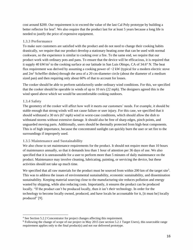
1.3.3 Performance
To make sure customers are satisfied with the product and do not need to change their cooking habits
drastically, we require that our product develop a stationary heating zone that can be used with normal
cookware, so the experience is similar to cooking over a fire. To the same end, we require that our
product work with ordinary pots and pans. To ensure that the device will be efficacious, it is required that
it supply 40 kW/m2 to the cooking surface at our latitude in San Luis Obispo, CA of 34.6° N. The heat
flux requirement was derived by assuming a cooking power of ~2 kW (typical for a modern electric stove
and 2m2 Scheffler dishes) through the area of a 20 cm-diameter circle (about the diameter of a medium
sized pan) and then requiring only about 60% of that to account for losses.
The cooker should be able to perform satisfactorily under ordinary wind conditions. For this, we specified
that the cooker should be operable in winds of up to 10 m/s (22 mph). The designers agreed this is the
wind speed above which we would be uncomfortable cooking outdoors.
1.3.4 Safety
The geometry of the cooker will affect how well it meets our customers’ needs. For example, it should be
stable enough that strong winds will not cause failure or user injury. For this case, we specified that it
should withstand a 30 m/s (67 mph) wind in worst-case conditions, which should allow the dish to
withstand storms without extensive damage. It should also be free of sharp edges, pinch points, and
unguarded moving parts. Additionally, users should be thermally protected from high-heat components.
This is of high importance, because the concentrated sunlight can quickly burn the user or set fire to the
surroundings if improperly used.
1.3.5 Maintenance and Sustainability
We also chose to set maintenance requirements for the product. It should not require more than 10 hours
of maintenance annually, so that it demands less than 1 hour of attention per 36 days of use. We also
specified that it is unreasonable for a user to perform more than 5 minutes of daily maintenance on the
product. Maintenance may involve cleaning, lubricating, painting, or servicing the device, but these
activities should not take up much time.
We specified that all raw materials for the product must be sourced from within 200 km of the target site5.
This was to address the issues of environmental sustainability, economic sustainability, and dissemination
sustainability. Keeping material sourcing close to the manufacturing site reduces pollution and energy
wasted by shipping, while also reducing costs. Importantly, it ensures the product can be produced
locally. “If the product can’t be produced locally, then it isn’t their technology. In order for the
technology to become locally owned, produced, and have locals be accountable for it, [it must be] locally
produced” [9].
4 See Section 5.2.2 Concentrator for project changes affecting this requirement. 5 Following the change of scope of our project in May 2015 (see section 5.2.1 Target Users), this sourceable range
requirement applies only to the final product(s) and not our delivered prototype.

17
1.4 Year-Long Plan
Here we break down the stages of the development of our product by the winter, spring, and fall academic
terms.
1.4.1 Winter
At this point in the design process, our main focus was research. After partnering with Dr. Schwartz and
establishing ourselves as a team, we began to investigate current solutions to the main problem: cook food
in a sustainable fashion. We concentrated this research on solar concentrators and their use in solar
cooking. Once we had a grasp of the subject matter and had met with Dr. Schwartz, we began creating the
QFD. Here we outlined the project requirements as discussed previously.
Following completion of the QFD, we began ideation. We continued our research into different methods
of solar cooking to develop as many solutions as possible for the problem. Towards the end of winter
quarter, we entered the design selection process, which is documented in section 3.2 Top Concepts.
1.4.2 Spring
Starting at the beginning of spring quarter, we began in-depth design work in preparation for construction
of our product. This included testing of materials and organizing a set of technical drawings. Throughout
spring quarter we worked towards the implementation and construction of a full scale product.
During this time, we completed the analysis of our design. Halfway through spring quarter, we expanded
on our Preliminary Design Report to reflect the new information we learned through research,
experimentation, and construction. This was presented to our sponsor and advisor in the form of a Critical
Design Report (CDR). This report included a full description of our design, complete technical drawings,
safety and failure mode considerations, and supporting analysis.
After this report we continued with the construction of our device. At the end of spring quarter we
reported our progress to Dr. Schwartz in the form of a project update report.
1.4.3 Fall
In fall, we completed construction, analysis, and testing. The testing included design verification to
determine whether the product accurately met the engineering specifications and the customer
requirements. Modifications were made to the design to optimize its performance and overall usability.
The results of the analysis were compiled over the course of fall quarter and used to create this Final
Project Report. This report is an extension of the Critical Design Report and includes everything we
learned previously. It includes the full design of the product, technical drawings for manufacturing,
testing results, and additional analysis.

18
2. Background This section includes details on existing solar cooking products and relevant solar cooking standards. The
purpose of this section is to establish the baselines and norms of the contemporary solar cooking industry.
2.1 Existing Products
There are numerous solar cooker designs that are used throughout the world. The category that is most
similar to our product is also the least prevalent: the off-axis parabolic concentrator.
The most well-known product similar to our device is the Scheffler Reflector. This device, created by the
German engineer Wolfgang Scheffler, is an off-axis parabolic dish. It tracks the sun’s daily movement
with rotation of the concentrator and the sun’s seasonal movement by changing the shape of the
concentrator.
The next closest type of solar cooker is the on-axis parabolic cooker. This has many more variations,
including the Balcony Cooker, the SolSource, the Sun Chef, the Solar Flame, the Cookup 200, and more.
These dishes all use the same geometric principles with small variations in material use and support
systems. The dual mirror concept is different than all of these due to the introduction of the tracking
heliostat. Occasionally parabolic dishes will add a plane mirror after the concentrator to change the
orientation of the focusing light, however no designs that we found used a plane mirror before a
concentrator to provide a constant light source.
2.2 Applicable Standards
While the solar cooking community is relatively small, there are a number of standards worldwide. For
instance, Nepal has a set of standards specifying design requirements that must be met. However, no such
specifications exist in America and no design specifications are accepted worldwide by the solar cooking
community. There are substantially more standards when it comes to the performance testing of solar
cookers. This is partially due to the fickle nature of testing, which is dependent on the weather, an ever
changing factor. Performance tests include: the Water Boiling Test Version 4.2.3; the ASAE s580.1; the
IS 13429 1-3; the Controlled Cooking Test; and the Kitchen Performance Test. We used these tests as the
basis for our performance testing.

19
3. Design Development This section details the design process of our product. In our design process it was important to
thoroughly investigate all possible solution avenues, and so this section details the concept generation and
selection methods used to assure the best choices.
3.1 Concept Generation
To create a wealth of ideas, we conducted research on existing designs, searched patented products, and
employed some creative thinking processes. Most of our initial concepts were generated by brainstorming
as a team, seeking combinations and simplifications of ways to concentrate light. Much of our later ideas
were inspired by the research we were doing in parallel and conversations with Dr. Schwartz. We came
across numerous innovative ways of concentrating light, including Fresnel lenses, glass spheres, adapted
umbrellas and satellite dishes, old television lenses, collapsible and portable designs, various
implementations of parabolas, and many more. While thinking creatively about potential solutions, we
guided ourselves with the primary function of the product, which was to cook food by focusing sunlight.
To help aid our understanding of this requirement, we experimented with some crude small scale models,
seen in Figure 5. These models helped us better intuit ways of concentrating sunlight to create a “hot
spot.”
3.2 Top Concepts
From the various concepts generated, the following were our top six.
This first of our ideas was inspired by one of the more prevalent existing solar cookers, the on-axis
paraboloid concentrator. This idea uses the geometric property of a parabola that rays incident to the
concave side of a parabola are reflected to a single point, known as the focus. This property is illustrated
in Figure 6A below. Figure 6B is a hand sketch of our concept.
Figure 5. Small scale models used to facilitate understanding of how to concentrate sunlight. Models were
built with wooden skewers, scrap Mylar, and foam core.
20
Our concept features dual-axis tracking to compensate for the daily and annual changes in the sun’s
position in the sky. The daily tracking axis could be adapted with a motor, as shown. The seasonal
tracking axis would require manual adjustment on a regular basis. This concept features relatively simple
construction and an efficient geometry. That is to say that the form is relatively tolerant of geometric
imperfections, and that the ratio of reflective surface area to the area of concentrated light is relatively
high, compared to an off-axis paraboloid section, discussed later on. Some issues with this design are that
it can be difficult for the user to reach the food at the center of a large dish, and the device cannot be used
to cook inside.
Our next idea was to make a concentrating lens from water and a transparent vinyl sheet. We could
improve on the design by Dan Rojas, shown in Figure 7A, next page. Figure 7B is our sketch of the
design—which we termed the “floating puddle”—with our modifications to improve performance.
A planar tracking mirror was introduced because the existing design only worked when the sun was
directly overhead. This design is very inexpensive and the materials would be easy to source. However,
the device has to be quite large to concentrate enough sunlight, the “puddle’ would evaporate and cease to
A B
B A
Figure 7. "Floating Puddle" concept based on Rojas' design (A) [11], and our sketch of a modified design
that compensates for the daily motion of the sun (B).
Figure 6. Focusing reflective geometric property of a parabola (A) and hand sketch of our
conceptual design (B).

21
focus if disturbed by wind, and there are considerable inefficiencies associated with the transmission of
radiation through the water and the plastic.
Another concept we considered was the existing Scheffler design. This is the state of the art in solar
cookers. It uses a dish in the shape of an off-axis paraboloid section, which deforms to compensate for the
seasonal variations of the sun. It rotates about a fixed axis to track the sun during the day, using a
clockwork mechanism driven by a weight. Figure 8 is a conceptual diagram of the design.
The Scheffler is an efficient and reliable design. It also directs the heat away from itself, creating an
unobstructed heat zone that can be easily used for cooking. However, the construction is complicated and
requires trained craftsmen to execute it properly. Both the dish and the tracking mechanism have very
tight tolerances, which are challenging to meet in a developing community.
We also generated the concept of using a rigid glass or plastic lens to focus light. A Fresnel lens is an
efficient way to focus incoming light with great accuracy. The lens must be on the line between the focal
point and the sun, so to heat a pot from below, we mounted the mirror lower than the food and used a
mirror to track the sun and direct it at the lens throughout the day. Our concept sketch is seen in Figure 9.
Figure 8. Conceptual diagram of a Scheffler dish, which
has a focal point that remains fixed relative to the ground.
Figure 9. Sketch of Fresnel lens concentrator concept showing
relative positions and tracking device.

22
The lens concept’s strength was that lenses can be purchased ready-made with high quality geometry due
to their history of use in other applications. However, the cost of a large, accurate lens is high, and
sourcing one in a developing community would be challenging. Additionally, a Fresnel lens’ surface
ridges make it difficult to clean out any dust or grit that would settle on its surface. This opaque layer
would significantly reduce the lens’ efficiency.
Another idea that came forward as a top concept used two reflectors. The first is a plane mirror that tracks
the sun throughout the day and keeps it directed at the same area, as seen in some of the preceding
concepts. The second reflector is an off-axis paraboloid section that concentrates the light from the plane
mirror to the cooking point. As far as we could determine, no existing designs are similar to this
configuration, shown in Figure 10.
This design allowed for the concentrating reflector to be sheltered as it is kept on the ground near a wall.
Like the Scheffler, it would also create an easy-access unobstructed heat zone, but its advantage over the
Scheffler is that it doesn’t require a deformable dish. Although the concentrator dish is not deformable, it
does still need to be a precise paraboloid section. Another drawback is that there is some loss in efficiency
at both reflective surfaces, instead of just at one.
The final of our top six concepts employed a heat transfer fluid, heated by a parabolic trough. A tracking
system rotates the trough to follow the sun during the day, which continually heats a heated fluid, such as
sunflower seed oil. The heating process causes convective circulation, leading to a constant supply of hot
oil at the top of the reservoir, where food can be cooked. See Figure 11.
A B
Figure 10. Concept sketches for a dual-mirror system layout (A) and a potential seasonal compensation
system design (B).
Figure 11. Parabolic trough concept, where a
high-temperature fluid carries heat to the
cooking interface.

23
This approach is different in that the concentrated sunlight is not directly cooking any food. The benefits
include the simpler geometry of a parabolic trough and the ease of routing the heat to any desired
location. The fluid reservoir could also be used for space heating or for cooking after dark, due to the
thermal energy stored by the fluid. However, the cost of the fluid would be high, as would the expenses of
the piping and fluid maintenance. There are also the issues of a lower efficiency due to conduction and
the issue of a long start-up time to get the fluid up to cooking temperatures.
3.3 Selection Process
To choose the best design, we coupled our engineering judgment and experience with two forms of
comparative matrices.
The first, called a Pugh matrix, compared each idea to a datum, or baseline, idea by scoring either +, 0, or
- as an indication of meeting each customer requirement better, the same, or worse than the datum. The
results often do not reflect how much better or how much worse, because the symbols omit information
about the magnitude of each rating. For example, a minus could be an extreme issue, but the Pugh matrix
doesn’t reflect this. The benefit of the Pugh matrices, then, is that they led us as designers to examine why
certain ideas scored well or poorly when we did not expect it.
The second form of matrix was a weighted decision matrix, which assigned numerical weights to each
customer requirement to reflect their relative importance to the success of the product. Each product is
then assigned a numerical rating for how well it meets each criterion. The weighted ratings are then
summed and can be compared to give insight into how well each design measures up to the others. Refer
to Appendix C: Decision Matrices for the weighted decision matrices, logbooks for Pugh matrices, and
Appendix B: Quality Function Deployment for customer requirements.
We used these decision tools to compare what we believed to be the best choice of concept with a detailed
consideration of how well each concept would perform. It was based on the combination of our judgment
and the results from these tools that we selected our concept.
3.4 Selection
Through our selection process, it became clear that one design stood out from the rest: the Dual Mirror.
This design provides a balance of performance, usability, and cost that made it stand out from our other
ideas.
Our main tool to choose our design was our decision matrix (see Appendix C: Decision Matrices). This
tool clearly displays the attributes and shortcomings of each design. Through analysis of the decision
matrix and in depth discussion of its results, we came to the conclusion that the Dual Mirror was better
suited to our requirements than each of the other designs.
The Dual Mirror design scored higher than any other design, scoring a whole 9 points better than the
second best design, the lens. These two designs scored similarly on many of the categories, with the dual
mirror taking the lead in a few key sections. On a daily basis, a user of the dual mirror would input less
time than as user of the lens due to the geometry of the lens. The design would utilize a Fresnel lens,
which approximates a regular lens in a single plane through the use of concentric ridges. These ridges
would fill easily with debris and quickly decrease the performance of the mirror, requiring daily input to
ensure optimum performance. This lens is also a specialty item, which increases the cost of the product
considerably. While the lens design could be slightly more compact, the benefits of the dual mirror easily
outweigh this consideration.

24
The third best design was the Scheffler at 10 points less than the Dual Mirror. Basic analysis showed that
this design would actually perform better than the dual mirror; however, it has other shortcomings that
make it less than ideal. Firstly, the deformable nature of the concentrator increases cost, complicates
construction, and worsens the user interface. Despite the slight inefficiency caused by a second mirror, the
Dual Mirror has comparable power output, as shown by our calculations. We came to the conclusion that
the Scheffler method is better suited for communities that are constructing large scale systems like that of
Abu Road, Rajastan [8].
The next best idea was the Heat Transfer Fluid. This idea was very promising at first; the ability to route
heat to any desirable location through piping was very appealing in regards to our purpose of building a
solar kitchen. However, we found that it had shortcomings the Dual Mirror did not. Firstly, the heat
transfer fluid itself would be expensive: water cannot be used due to the danger of steam creation in the
pipes at the concentrator and all alternatives (e.g. sunflower seed oil) are relatively expensive and
unavailable in third world countries. Secondly, due to scarcity of support and resources, any issues caused
by plumbing could cause the device to stop functioning. Despite the construction advantages of having a
parabolic trough as opposed to an off axis paraboloid, we decided the Heat Transfer Fluid was not the
design we wanted.
The other three design concepts scored even lower than these previously presented. They ran into
problems with reliability (Floating Puddle), inability to cook inside (On Axis Paraboloid), product life
(Cal Poly’s), among other issues. We determined that the Dual Mirror would better meet our customer’s
and sponsor’s requirements than each of these other designs.

25
4. Proposed Design This section investigates the chosen concept by providing a complete description of the geometry,
materials, manufacturing processes, and testing plans. The design presented in this section was proposed
at the time of the CDR. Changes have been made following the CDR throughout the end of spring quarter
and the entirety of fall quarter, and are documented in Section 5.2 Design Changes since the Critical
Design Report.
4.1 Design Details
Our design is subdivided into two parts: the heliostat (also referred to in this report as the reflector or
primary reflector) and the concentrator. The heliostat redirects sunlight such that the concentrator receives
optimal irradiation. In this section we offer the details of these two main parts of the design.
4.1.1 Reflector
The reflector, as seen in Figure 12, consists of a plane mirror with 3 main geometric concerns: latitude,
daily tracking, and seasonal tracking.
The rotation of the plane mirror is driven by a
small motor to follow the daily movement of the
sun. This small motor is controlled by a relatively
small, analog circuit and powered by a 12V
battery. The circuit consists of two photoresistors,
regular resistors, an op-amp comparator, a DC
relay, a breadboard, and a rechargeable battery.
The two photoresistors are used to detect the
position of the sun: when one of the photo-
resistors does not receive sunlight, the circuit will
rotate the mirror to directly face the sun. This
results in discrete movements of the mirror with a
time delay. This is advantageous over a directly
connected motor that continuously turns the
mirror, as the continuous motion quickly drains
the battery. Our motor will rotate the mirror via of
a string drive. This provides a large moment arm
in a cost effective method. The rotational axis is
secured on one side by a pin joint, and on the
other side by a concentric half-pipe. The bottom
end of the rotational pipe is fixed with an endcap,
with a small bowl bored in the center, which mates with a bolt milled to a point, providing a low-cost,
low-friction bearing. At the high end, the rotating pipe is cupped by a half-pipe, supporting the vertical
load, while a bolt protruding out the top resists axial load.
The rotational axis must be specifically angled relative to level ground to compensate for latitude
differences. This is executed properly by making the angle of the axis of rotation with respect to
horizontal equal to the local latitude, thus producing an axis parallel to the Earth’s. By angling the
reflector towards the equator (due South, for our Northern Hemisphere location), light can then be
Figure 12. A 3D rendering of the primary reflector

26
reflected onto a concentrator on the equator-side of the reflector. In order to ensure the incoming light
provides a constant irradiation at an unchanging angle, the reflector must direct the light so it is parallel to
the rotational axis (and Earth’s axis). Thus, the rotational axis must be in line with the axis of the
paraboloid as seen in Figure 13. This is accomplished by support the pin joint and the concentric pipe by
angled steel plates clamped to steel pipes that serve as the legs of the frame.
Additionally, the heliostat must adjust to compensate for the seasonal change of the Sun’s path through
the sky. To account for this change, the angle of our reflector with respect to the rotational axis must vary
between 33° and 57°. This is true for any latitude, because the seasonal variation is directly related to the
angle of inclination of the Earth’s rotational axis. Initially, we thought to accomplish this through a rigid
rod attaching the back of the reflector frame to a small pipe, concentric to the rotational pipe, which could
be fixed in place by a pin fitting into a hole in the small pipe and a set of holes in the rotational pipe. To
increase the rigidity of the frame, we have opted for two rigid rods, and to increase resolution of the
seasonal adjustment, we opted for a pair of set screws instead of the quick-release pin (See Figure 14).
This is beneficial, as the change in angle of the mirror is not discretized throughout the year, but instead
varies continuously.
Figure 13. A 3D layout of the overall system

27
Figure 14. Conceptual (A) and revised (B) design of seasonal adjustment for the primary reflector
4.1.2 Concentrator
The design of the concentrator was not finalized to the same extent as the heliostat at the time the CDR
was authored. A number of different manufacturing techniques have been explored at Cal Poly
previously, none of which we were comfortable with settling on before understanding firsthand the
challenges of manufacturing a paraboloid surface. To improve our understanding and better inform our
design choices, we opted to build a small scale prototype.
The construction technique we chose for the prototype involved building a mold for the paraboloid
surface, then laying up and gluing together a lattice of wood lath in this mold. Finally, reflective Mylar
strips were affixed to the finished lattice.
The mold was created by revolving a parabolic pattern about its axis, sweeping out a parabolic profile in a
shallow hole in the earth at the Student Experimental Farm. We chose to make the mold this way because
it is close to the first principles of a paraboloid, literally revolving a parabolic path in space. The parabolic
profile was created by marking and connecting points on a piece of thin plywood, whose locations were
calculated and mapped in Cartesian coordinates. The points were connected and then this profile was cut
out. The cutout was next affixed to an axle and supported so that it would sweep out a shallow hole in the
ground when revolved.
Next, the hole was dug such that there remained roughly 1cm between the solid earth and the wood
pattern throughout the range of its sweep. Then a thin layer of a cement-like mixture of water, sand, and
clay was spread in the shallow hole. By sweeping back and forth with the pattern, it could be seen where
the mixture needed to be lower of higher. The pattern was swept back and forth and the mixture
redistributed until it was only just in contact with the pattern throughout its range. The mold was then
allowed to cure. Figure 15 shows the parabolic pattern and mold after sweeping out a uniform surface.
A B
Single
rod
Discrete
adjustment
holes
Dual
rods
Slider uses
set screws

28
Figure 15. Parabolic profile sweep setup with finished mold surface. When revolved about the axis, the
pattern lightly contacts the light brown concrete-like mixture evenly.
Once cured, narrow wooden lath was placed in the mold in two orthogonal layers. The top layer was
chosen to run concentric to the parabolic axis to aid with adhering the reflective material later. A dab of
glue was placed at each point where the slats crossed, then the assembly was pressed in place by burying
it in dirt. The wood and the pressing dirt were separated by a layer of heavy plastic. The glue was allowed
to cure for two days. Figure 16 shows the results.
Axis
PVC pipe
axis fixture
Wooden
axis fixture
Parabolic
pattern
Figure 16. Wooden lath frame, weighted down by bricks after
pressing dirt and plastic were removed. The bricks were necessary
because the elasticity of the wood caused the frame to separate
slightly from the mold.
Top layer slats
are concentric
to parabolic axis

29
Once cured, the wooden frame was removed. Sheets of Mylar were cut to span the distance between the
slats of the top layer, and then affixed using a single staple in the center, followed by tape. Figure 17
shows the finished prototype.
In building the concentrator this way, we learned that the wood lath frame was too springy; once the
frame was removed from the mold, it sprung back slightly towards its original planar shape. We also
learned about the criticality of imperfections in the reflective surface. It was important not to over-
constrain the reflective material, because it would introduce unwanted distortions. The Mylar used was
wrinkled and had dents and smudges, seen in Figure 17 as the distorted reflections in the surface of the
reflector. These imperfections significantly scattered the light received, producing a very crude focal
point. We believe these are the primary sources of imperfection in our construction technique. The
method was a success in that it produced an effective concentrator, with which we were able to burn large
holes in a piece of black foam core board.
With these results, we could make a well-informed and structured decision about the best—or hybrid of—
known concentrator construction methods. Section 5.2.2 Concentrator details our ultimate decision on
construction of the concentrator.
4.2 Material Selection and Production
We selected materials to best meet our design requirements. For the frame, the main considerations were
strength, durability, ease of manufacture, and cost. For the mirrors, there was the added consideration of
reflectivity. Additionally, we considered each material’s availability and manufacturability in developing
countries. While we designed the product to be calibrated and used in San Luis Obispo, where we had
access to extensive fabrication technologies, we kept the design simple and manufacturable regardless of
location.
Figure 17. Completed prototype with Mylar strips adhered to wooden frame.

30
4.2.1 Reflector
The majority of the reflector used off-the-shelf parts. The mirrors themselves are 1’x4’ bedroom mirrors
mounted onto a 4’x5’ plywood sheet. The mirrors are low cost and have adequate reflectivity, while the
plywood is low cost and sufficiently strong. The frame itself consists primarily of 1.5” schedule 40 steel
pipe with off-the-shelf brackets and mounts. The steel is a common building material and easy to work
with, since it is weldable. It is also robust and durable.
4.2.2 Concentrator
The concentrator requires attention to detail in its manufacture and material selection. To achieve an
acceptable efficiency, the geometry of the dish must be very precise. We investigated the use of a cob
mold to shape wooden strips into the correct shape. This mold could be easily created with readily
available materials at low cost using a plywood parabolic profile swept through a wet mixture which is
then cured (see Section 4.1.2 Concentrator). The choice of reflective material depends on reflectivity and
durability. The efficiency of our product is quickly compromised by surface imperfections like dents,
scratches, and contaminants. We recommend reflective aluminum in our final design, as it is more
resistant to deformation that Mylar and has a comparable reflectivity. We weigh resistance to deformation
heavily because accidental bends or even the slightest of curvature anomalies can have significant effects
on the concentration of the light, and Mylar is more susceptible to more sudden changes in curvature.
4.3 Analysis Results
As a tool in our design process, we have analyzed critical design features to learn more about the system
and to lend confidence to our decisions. Notably among these are the correlations between
Concentrator size and cooking power,
Reflector deflection and concentration,
Heliostat construction and out-of-plane deflection,
Reflector construction and torque requirements, and
Reflector weight and deflection.
This section summarizes the results from these investigations. Refer to Appendix D: Detailed Analysis for
complete calculations.
4.3.1 Concentrator Size and Cooking Power
The measure of cooking power we are using is an area density, kW/m2, which captures the combination
of two properties: the total power delivered and the area it is distributed to. The total power delivered is
proportional to the irradiation area of the concentrator, and the area of distribution is related to the
geometric accuracy of the concentrator.
To calculate the size of the concentrator needed for our cooking power requirement, we considered the
reflective efficiencies and construction inaccuracies as power losses, then back-solved for the irradiation
area required, knowing the average insolation for our location. We found that we will require a roughly
1.13 m2 irradiation area.
4.3.2 Reflector Deflection and Efficiency
For a perfect system, the heliostat reflector is perfectly planar, and so if incident rays are parallel, then all
reflected rays are parallel. The geometric principle of the paraboloid concentrator we are employing is
that rays parallel to the paraboloid’s axis and incident to the concave face of a paraboloid are reflected to

31
the focal point. When incident rays are not parallel, they are not reflected to converge at the parabola’s
focus; instead they may not focus at all or will focus at some other point. For our system, it was important
to understand how deflection of the primary reflector would affect concentration at the focus.
We modeled the system with a reflector of circular curvature and an ideal concentrator. We adjusted the
offset at the peripheral ends from the ideal reflector to the actual curved reflector surface, and observed
the change in focal width at the theoretical focal point. Figure 18 below shows the ray tracing model
developed in Solidworks, used to explore this relationship between deflection and concentration.
4.3.3 Heliostat Construction and Out-Of-Plane Deflection
With an understanding of how tolerant the system is of reflector deformation, we needed to verify that the
construction of our reflector would not permit excessive deformation. We modeled the reflector surface as
a beam in bending under its own weight, treating the components as homogenous materials. We assumed
the plywood was perfectly bonded to the beams behind it. The analysis took advantage of the symmetry in
the system, and considered only a 2D model of the reflector. This meant that weight densities were
collapsed to a single plane and considered in units of weight per length. Worst-case material properties
and reflector orientation were used to yield a conservative analysis.
The results from the beam theory analysis indicated a peripheral deflection of about 3 mm, which is
allowable based on the results of our ray tracing. As seen in Figure 18, a deflection of 4.8 mm yields a
focal width of 8 cm, which is small enough to achieve our desired concentration.
Figure 18. Solidworks ray tracing sketch, assuming ideal concentrator and circular
reflector. Dimensions in meters.

32
4.3.4 Reflector Construction and Torque Requirements
In order to design the tracking motor and drive train system, we needed to know how much torque would
be required to turn the daily tracking axle. We considered torques due to friction in the bearings and the
torque required to accelerate the reflector at 0.5 rpm/s. we found that 2.26 N-m (20.0 in-lbf) of torque is
needed to move the reflector as desired.
4.3.5 Reflector Weight and Deflection
To be sure the part used for the daily tracking axis was sturdy enough, we checked the deflection it would
undergo due to its weight and the weight of the reflector. The axle was modeled as a simply supported
beam in bending subject to a distributed load and a point load. The model assumed the beam was
horizontal, and thus yielded a conservative estimate. The weight of the reflector was taken from the
Solidworks model of the reflector assembly, which accounts for component volumes and densities. We
found that the beam would deflect by less roughly 1 mm (.04 in). This is an acceptable deflection because
it will not impair the operation of the reflector.
4.4 Cost Analysis
This section presents the costs the project is expected to incur. Project costs primarily consist of the
material costs of constructing the prototype, outlined in Table 2.
The majority of the cost of the heliostat frame is hardware, priced according to McMaster-Carr and Home
Depot. The reflector will be the second most expensive part of the prototype, where nearly half the cost is
the glass mirrors sourced from Home Depot. The tracking circuit cost includes circuit elements and the
motor mount. The total cost is only 11% over our $200 budget.
Refer to Appendix D: Vendors and Pricing for detailed a detailed cost breakdown.
4.5 Schematics
A full set of drawings for the construction of the Reflector is available in Appendix J: Technical
Drawings.
4.6 Safety Considerations
To safeguard against potential failures that may result in damage to the product or users, we completed a
Failure Modes and Effects Analysis (FMEA). In this analysis, we carefully considered all the modes of
failure possible for each subsystem and component. Possible causes or mechanisms for each potential
failure mode were then explored, and all of these combinations were scored based on their severity and
likelihood of occurrence. The criticality of each potential failure mode and effect was quantified as the
product of the severity and occurrence scores; thus, a high severity and a high likelihood compound to
Table 2. Actual costs for heliostat system
prototype
Subsystem Projected Cost
Heliostat Frame $ 102.31
Heliostat Reflector $ 70.81
Tracking Circuit $ 38.44
TOTAL $ 221.51

33
denote a critical item that needs attention. For items with criticality above 20 (out of 100 possible), we
have proposed solutions that were incorporated into the design.
The items with the highest criticality are failures that significantly compromise the cooking power of the
product. The items of greatest criticality involved the imperfections, degradation, or wear on the reflective
surfaces. To address these, we proposed methods of refining construction and maintenance schedule.
Refer to Appendix I: Potential Failure Modes and Effects Analysis for complete details.
Based on the results of the FMEA, we did not identify any major safety concerns with our concentrator.
The FMEA was continued until the conclusion of our project to be sure that all possible safety hazards
have been identified and addressed.
4.7 Maintenance and Repair
Maintenance and repair are guaranteed issues concerning products like our dual mirror system, which will
receive use almost every day and be exposed to the elements.
In order to maintain adequate power to the cooking surface, both the reflector and mirror will have to be
cleaned regularly. The actual frequency of this process was determined in the fall as explained in the
Design Verification Plan in Appendix E: Design Verification Plan. Additional maintenance will likely be
require as well.
The string in the string drive motor system will likely wear over time and fail. This part is cheaply and
easily replaceable with little to no tools required. The pivot points of the reflector will need regular
application of grease in order to ensure the reflector can rotate properly without overly stressing the
motor.

34
5. Product Realization
At the time of the CDR, little actual construction had taken place. Since then, the design was altered, the
product was created, and much knowledge was gained. This section outlines the manufacturing process,
changes to the project since the CDR, and recommendations for the future.
5.1 Fall Construction
The week before class began fall quarter, we picked up where we left off at the end of spring quarter. This
began with the rapid construction of a 1/5th scale prototype to ensure that our design was feasible. This
was shortly followed by the manufacturing of all necessary parts and the design and creation of the
tracking circuit. The manufacturing of the parts included cutting components to size, welding components
together, and drilling holes for assembly. The tracking circuit required consultation from an EE student
and an EE professor, multiple iterations of the design, and creation of a computer model. These two tasks
were completed at the end of week 5. A temporary stand was designed and built to hold the product until
its planned in-ground installation after the Senior Expo, and the components were assembled into their
subassemblies. Finally, the pieces were brought together. At this point, a number of small issues
presented themselves. The following weeks were spent redesigning these small subsystems (e.g. the
tensioner system). The date of testing had to be pushed back during this time. Finally, we attempted to
combine the concentrator and heliostat and begin testing. This proved harder than expected as the
concentrator had not retained the ideal geometry and was difficult to secure. This setback pushed testing
back further. Finally, the product was finished and testing was started.
5.2 Design Changes since the Critical Design Report
There are a number of changes to the design since May. There are two main changes regarding the scope
of the project, and a number of small design tweaks to improve manufacturability/ease of use.
5.2.1 Target Users
In late May of 2015, it was confirmed that Dr. Schwartz’s contact in Yemen was not interested in our
work. Since we were no longer designing for a particular community, we lifted our requirement for our
proof-of-concept prototype that our design be made with materials sourceable within a reasonable range
of the target community, since we could not know in which community our cooker would be
implemented. However, we still wanted to make sure the parts of our prototype could easily be replaced
with equally functional components that would be attainable at similar cost in potential target
communities. Our prototype reflects this intent.
5.2.2 Concentrator
Over summer, Dr. Schwartz suggested that we could begin testing earlier if we used an existing
concentrator instead of waiting until that portion of the manufacturing was complete. This idea was
retained until the beginning of fall quarter, during which time it became apparent that we were going to
run into time constraints due to manufacturing. As the creation of a new concentrator is not necessary for
design verification of the dual mirror concept, we decided to narrow the scope of our project to only
include the heliostat. Our final product reflects this change, with the heliostat and associated tracking
systems newly fabricated and the concentrator borrowed from a previous project.

35
5.2.3 Seasonal Adjustment
At the time of the CDR, our seasonal adjustment consisted of two rigid rods with eyehooks on either end
that connected the upper mirror assembly to the rotating axis via a concentric pipe fixed with set screws.
Shortly following the CDR, we realized a much simpler method of accomplishing the necessary degrees
of freedom. To execute it, we created metal support rods as shown in Figure 19 whose pins on either end
were parallel. This avoids the out-of-plane complications that encumbered the previous design.
Figure 19. Close up of the new seasonal adjustment support
rod design.

36
5.2.4 String Guide/tensioner
We also made a number of changes to the daily tracking. The first change was made both for ease of
manufacture and cost reasons. We eliminated the semicircular string guide and added a pulley and large
deformation spring to supply the motor adequate tension. We found that the semicircular guide would be
hard to manufacture, especially in a developing country, and a similar result could be obtained by
eliminating the string guide, adding a larger displacement string, and adding a pulley to direct the string
around the hinge board as seen in Figure 20.
5.2.5 Tracking Circuit and Power Source
Over the summer between spring and fall quarter, we began work on creating the tracking circuit by
talking to undergraduate electrical engineering student Nick Hayes. With his advice, we were able to
figure out the necessary components to create the circuit seen below in Figure 21.
Figure 20. String tensionr system. Used to eliminate slack in the daily tracking
system as the geometry of the string drive changes with the rotation of the heliostat.

37
Figure 21. Tracking circuit: used to detect movement of the sun and actuate the motor to orient the
heliostat.
This circuit consists of only IC’s and discrete circuit elements (exact specifications can be found below in
Table 3) to detect changing sunlight and actuate the motor. It is currently powered by a 12V power
source, but ideally this could be replaced by a rechargeable battery and charging solar panel. Two photo
resistors are placed on either side of the Photocomparator Divider (Drawing P001) on the
Photocomparator Base (P002). The divider projects perpendicular to the heliostat surface; when the sun
position moves, it casts a shadow on the east side of the Photocomparator base and the east photoresistor.
This changes the resistance of said photoresistor. The comparator receives two input voltages dependent
on the resistance of the two photoresistors and, when the west photoresistor detects sunlight and the east
does not, triggers the relay which actuates the motor. When cloud cover casts shadow on the heliostat, the
resistance of both photoresistors will change and the voltage difference will not be sufficient to trigger the
comparator. This allows the heliostat to track the sun’s movement without being confused by cloud cover.
Table 3. Tracking Circuit Component Specifications
Circuit Component Specifications
Motor Amico a12032000ux0190
Relay TE OUAZ-SS-112D
Comparator LM 311
R1 1000Ω
R2 2200Ω
R3 150Ω
PR1 80Ω in direct sunlight, 600Ω in shade
PR2 80Ω in direct sunlight, 600Ω in shade
5.2.6 Top and Bottom Support
In order to increase the safety and sturdiness of our design, we made two small changes to the top and
bottom supports. We welded a bolt onto the top of the rotating pipe parallel to the pipe’s axis. This bolt
fits through a hole in the top bracket and a nut secures the top side of the assembly to the frame.

38
Secondly, we added a 2-inch section of semicircular pipe on the bottom support, which acts as a backup
support in the unlikely case that the pipe falls off of the pivot bolt.
5.2.7 Temporary Stand
Due to the fact that it was most convenient to build and test our product near the student shops and that
we must present our project at Senior Expo, we created a temporary stand for the device. The stand holds
the 4”x4”wooden post and secures the lower legs. This allows the device to be free-standing until it is
permanently mounted in the ground at the Student Experimental Farm. The lower two feet of each leg
will be sunk into a foundation to secure the device and ensure a long lifetime despite occasional strong
winds. Since this temporary stand is not something that someone would need to recreate our system, the
technical drawings for it are not included in this report.
5.3 Recommendations for Future Design Development
In the event that another group wishes to improve on our design, we recommend the following design
changes to improve the product.
5.3.1 Insulation Possibilities
Over the summer, we realized that our definition of the scope of our project was somewhat limiting. By
defining the project as ending at the hot spot, we neglected any changes that could be made at the hotspot.
As such, we designed our product to provide 1200 watts to the hot spot—60% of the power of a
conventional stovetop. However, with creative use of insulation and reflective material, we may have
been able to cook at a much lower power (decreasing the size and cost of the complicated heliostat and
concentrator) by surrounding the sides and top of the pot with sheep’s wool or similar insulation and
leaving the bottom open for the concentrated light. This does not negate the usefulness of our project, as
the concept has still been verified and insulation testing could be performed even with the larger scale
device by blocking a portion of the incoming light to adjust the input power. It is a potential area to
investigate and improve upon the current design.
5.3.2 Reflective Surface Coverings
We recommend that the reflective surfaces be covered with a light cloth to prevent animal intrusion and
potential damage to the surfaces.
5.3.3 Frame Alterations
There are two potential major changes to the frame: switch the configuration of the legs and lighten the
overall weight.
The current frame is built as a tripod of sorts, with two short legs in the front and one main support in the
back. We found that the two legs in front caused not two shadows on the concentrator, but four,
decreasing the efficiency more than expected. This is due to the sunlight casting a shadow from the legs
on the reflector and the redirected light casting a shadow of the legs on the concentrator. If the orientation
of the supports were to be flipped, with a central support in front and two support in the back, the
efficiency could be increased. We chose the current configuration for its structural stability however, so
this would have to be taken into account.
The second change would be to lighten the overall weight of the heliostat. The frame and heliostat are
together quite heavy: more than one person could safely move. Especially with the consideration of

39
insulation at the hotspot, it is likely that the frame could be streamlined to produce a more convenient and
manageable design.
One further alteration would be to include a means of locking the rotation of the daily tracking axis. This
would prevent inadvertent rotation due to wind, which could crash the mirror assembly into the tracking
motor bracket. We managed by bracing the mirror assembly with wood and spacer blocks temporarily.
5.3.4 Concentrator
We believe that the majority of our performance issues stem from inefficient concentration of the light by
the concentrator. We decided to eliminate the concentrator from our project scope because we knew that
previous projects at Cal Poly had created solar concentrators and that we could borrow one of these
concentrators to verify that our heliostat was properly working. However, at the time of this decision we
were not aware the magnitude to which the concentrator had deformed. If we had known, we may have
opted for a different course of action, but regardless we already were working overtime finishing the
heliostat. We recommend that a concentrator be constructed for this device and the old concentrator be
recycled. From the preliminary prototyping that we were able to complete, we found that a concentrator
could be constructed by sweeping a mold in the ground and laying mylar in this mold. We leave this as a
possibility for future development.
5.3.5 Tracking System
During our testing, we found that at the extremes of the heliostat rotation, the string began to slip on the
pulley. We recommend that the pulleys on the tensioner system and motor be switch to knurled aluminum
and the string be swapped for a coated cord.
The seasonal adjustment took a lot of trial and error to dial in properly. We recommend marking out on
the rotating pipe where the adjustment slider ought to be set to for evenly spaced times throughout the
year. Also, we recommend that the setscrews should be relocated on the slider pipe so as to eliminate slop
and unintentional pivoting. Currently they form an axis about which the slider pivots, introducing a small
angular range that the mirror assembly can freely rotate through. This range should be limited to improve
reliability and durability. Further, we recommend that a lever be permanently attached to each set screw
for ease of adjustment.
In the current design, the motor and tracking circuitry are directly exposed to the atmosphere. We
recommend that all electronic components be carefully protected from water intrusion to prevent a short
circuit.

40
6. Design Verification Following construction of the device, verification of the design was necessary to determine whether or not
the dual mirror concept met our requirements. Prior to construction, a full testing plan was created to
guide our testing efforts. This section lists the intended and completed tests.
6.1 Testing Procedures
We created six testing procedures to determine whether we adequately met our requirements. These can
be found in Appendix F: Testing Procedures. These tests are matched with specifications as shown in
Table 4.
Table 4. Test names and associated specification numbers
Test Name Spec #
Daily Setup Time 1
Maximum Input Force 2
Static Heat Spot 5
Static Heat Spot with Wind 5
Performance 11
Regular Maintenance 14
Not all tests were completed according to the original specifications after we realized that we over-
specified them; in using the product and performing some tests we learned enough by simple observation
that we could confidently say the other requirements were met without subjecting them to rigorous tests.
The requirements specified for testing in Table 1 are iterated below in Table 5 with the revised
requirements and compliance verification types.
Table 5. Revised specifications for testing formal requirements
6.2.1 Daily Setup Time
Daily setup included removing the chocking, manually rotating the mirror assembly to the start position,
removing coverings, seasonal adjustment as needed, and switching on the electronics. We did not
rigorously time these tasks, as could have been done with a stopwatch. Nevertheless, never in our
experience setting up the device did these tasks require more than 10 minutes.
Results: Setup requires less than 10 minutes.
6.2.2 Maximum Input Force
User inputs included manually rotating the mirror assembly, removing coverings, switching on
electronics, and performing seasonal adjustment as needed.
Results: In our experience using the machine, we never needed to exert a force in excess of 30 N.
Spec. # Parameter Description Requirement or Target Tolerance Compliance
1 Daily setup time 10 minutes Max. Observed
2 Maximum user input force 30 N Max. Observed
5 Static heat spot, relative to cooker True ± 5 cm Tested
7 Daily tracking axis inclination 34.6° ± 1° Inspected
8 Wind speed while operable 10 m/s Min. Not Tested
11 Power to cooking surface 40 kW/m2 ± 10 kW/m2 Tested
14 Daily maintenance 5 minutes Max. Observed

41
6.2.3 Static Heat Spot
This test was designed to verify that the heliostat did its job properly. If the heat spot was not static, it
would indicate either a problem with the daily tracking or seasonal adjustment. We could discern which
system was at fault because if the automated daily tracking functioned but the heat spot migrated, we
would know the seasonal adjustment was out of calibration.
Before this test, we verified that the tracking circuit triggered the motor as desired. As soon as the circuit
was completed, it was tested to ensure it would trigger when the correct photoresistor fell into shadow.
Results: The tracking circuit properly engages the motor and rotates the heliostat to properly reflect light
onto the concentrator whenever the east side photoresistor falls into shadow. This successfully kept the
entire concentrator supplied with light correcting for the azimuth angle. The seasonal adjustment easily
corrected for the elevation of the sun for the current season, although we had to run the system for a few
hours to get it dialed in properly.
6.2.4 Static Heat Spot, with Wind
In the end, we were unable to follow the testing procedure originally created to test for a static heat spot
in windy conditions. This was partially due to manufacturing setbacks, but mostly due to the weather not
cooperating during the days that we were able to test.
Nevertheless, we were able to obtain some preliminary results. Following its completion, we left the
device outside in the courtyard of Bonderson Projects Center. During a month-long period, the week of
October 19th was especially windy and reported outdoor wind speeds (maximum of 23 mph, or 10.3 m/s)
exceeded the testing wind speed. While the wind speed at the heliostat was not necessarily as high as the
reported maximums and we did not verify cooking ability in these conditions, it does demonstrate that the
device is able to withstand high winds without structural failure.
Results: The heliostat can withstand higher windspeeds than its predecessors. The exact magnitude is
unknown.
6.2.5 Performance
This test was based off of a performance testing standard published by ASABE (American Society of
Agricultural and Biological Engineers). The device was used to raise the temperature of water and the
power supplied to the hotspot was calculated from the energy absorbed by the water. A thermocouple data
logger system was used to record the temperature of the water; this can be found below in Figure 22.

42
Figure 22. Plot of temperature as a function of time demonstrating how the solar cooker heated up 2
kilograms of water.
We found the power supplied by the device at a water temperature 50 °C above ambient to be 35 Watts.
This is considerably lower than the required power of 1200 watts. We can account for some of this
difference when we take into account potential inefficiencies: the legs shadows, the washers, not perfectly
planar mirrors, inefficient reflectivity of the mirrors, and seasonal change of irradiation (the value of 1200
watts was calculated using summer values for irradiation and current irradiation values may be as low as
half of the summer values). However, all these together does not result in the performance obtained. The
light profile at the hot spot produced by the concentrator is roughly 40 cm in diameter, but is unevenly
distributed and partially scattered. While more testing is necessary to determine the exact cause of this
low performance, we believe that the main cause is the concentrator.
In addition to finding the average power delivered by the concentrator, we also found the power with
multiple time steps to give us a sense of the instantaneous heat transfer balance to the pot. This can be
seen below in Figure 23.
0
10
20
30
40
50
60
70
80
12:00 PM 12:15 PM 12:30 PM 12:45 PM 1:00 PM 1:15 PM 1:30 PM 1:45 PM 2:00 PM
Tem
per
atu
re [
°C]
Time [hr:min]

43
Figure 23. Instantaneous power absorbed at the hot spot with varying time steps.
Results: The device performs much worse than expected. This failure has a number of potential causes;
the primary cause we suspect is at fault is the concentrator’s improper geometry. We suggest the device
be tested with a more accurately shaped concentrator to thoroughly investigate the root cause of failure.
6.2.6 Maintenance
As previously stated, the device was left outside for the month prior to Senior Expo. During this time it
was exposed to three periods of rain, a wide variation in wind and sun, a cold snap, and a significant
amount of dust and grime created from the nearby machine shop. From our estimation, this has had
negligible effects on the power output and no effects on the structural integrity or user interaction with the
device.
-400
-300
-200
-100
0
100
200
300
400
12:45 13:00 13:15 13:30 13:45 14:00
Po
wer
[W
atts
]
Time [hr:min]
10 min Average
5 min Average
2 min Average
1 min Average
20 s Average

44
7. Conclusion This project was pitched to the mechanical engineering students by Dr. Pete Schwartz, a professor in the
Physics department. For some time, he has been involved in the field of solar cookers. These devices
attempt to solve a problem of two interconnected societal trends: the need to support the growing
population and the push to become sustainable and self-supporting. These two trends combine in many
ways, including a lack of sustainable, appropriate cooking technologies in developing countries. One
solution to this need is the solar cooker. Dr. Schwartz pitched the project to design and build a Dual-
Mirror Solar Cooker; while other solar cookers exist and use similar technologies, no other cookers use
this specific geometric design (the dual mirror has only been attempted once before, by a previous senior
project group at Cal Poly). This project was an attempt to verify the design concept, produce a working
model for testing purposes, and design a product for this concept that was reliable, cost effective, and
simply constructed.
This project began with research and analysis of the concept and how it compared to other designs on the
market. We determined that the dual mirror was a worthy approach to fulfilling the need, continued with
the design of the dual mirror system, created small and full scale prototypes, and tested this device for our
design verifications.
Throughout the course of the past year, we encountered many issues and setbacks and the device and
project changed accordingly. The largest change from our initial goal was the elimination of the
concentrator from the scope of the project. While this change was necessary in order for us to complete
the project and not necessarily vital to the verification of the concept, it did negatively impact the
outcome of the project. Upon completion of the heliostat, we tested the performance of the solar cooker
and found that it failed to meet our design specifications. A number of potential causes other than the
improper geometry of the concentrator can be found in Section 6.2.5. Following our testing, we have a
number of recommendations (these are fully elaborated in Section 5.3 Recommendations for Future
Design Development) for further investigation of this design: insulation at the hotspot should be
investigated to allow for a smaller scale device; a cover should be designed for the heliostat and
concentrator; the support structure should be investigated to eliminate shadows; most importantly a
concentrator with proper geometry should be constructed.
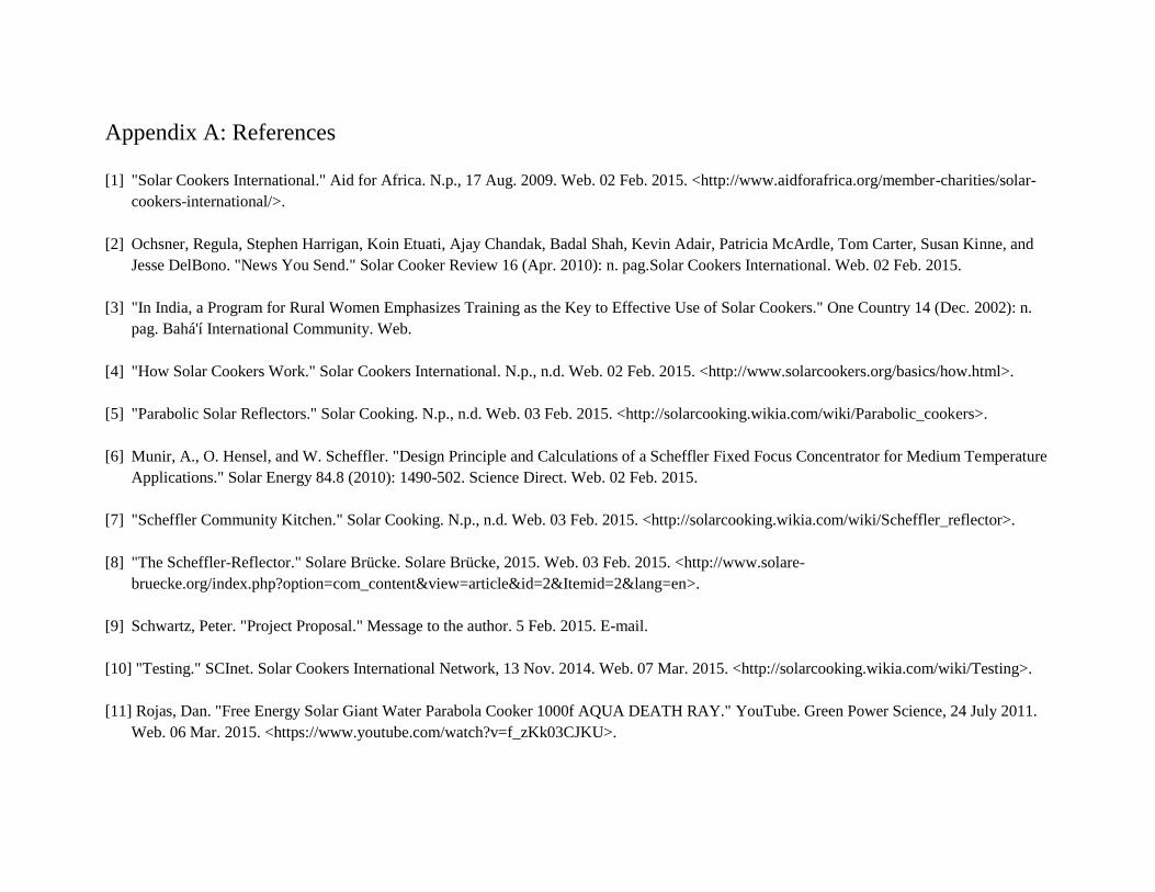
Appendix A: References
[1] "Solar Cookers International." Aid for Africa. N.p., 17 Aug. 2009. Web. 02 Feb. 2015. <http://www.aidforafrica.org/member-charities/solar-
cookers-international/>.
[2] Ochsner, Regula, Stephen Harrigan, Koin Etuati, Ajay Chandak, Badal Shah, Kevin Adair, Patricia McArdle, Tom Carter, Susan Kinne, and
Jesse DelBono. "News You Send." Solar Cooker Review 16 (Apr. 2010): n. pag.Solar Cookers International. Web. 02 Feb. 2015.
[3] "In India, a Program for Rural Women Emphasizes Training as the Key to Effective Use of Solar Cookers." One Country 14 (Dec. 2002): n.
pag. Bahá'í International Community. Web.
[4] "How Solar Cookers Work." Solar Cookers International. N.p., n.d. Web. 02 Feb. 2015. <http://www.solarcookers.org/basics/how.html>.
[5] "Parabolic Solar Reflectors." Solar Cooking. N.p., n.d. Web. 03 Feb. 2015. <http://solarcooking.wikia.com/wiki/Parabolic_cookers>.
[6] Munir, A., O. Hensel, and W. Scheffler. "Design Principle and Calculations of a Scheffler Fixed Focus Concentrator for Medium Temperature
Applications." Solar Energy 84.8 (2010): 1490-502. Science Direct. Web. 02 Feb. 2015.
[7] "Scheffler Community Kitchen." Solar Cooking. N.p., n.d. Web. 03 Feb. 2015. <http://solarcooking.wikia.com/wiki/Scheffler_reflector>.
[8] "The Scheffler-Reflector." Solare Brücke. Solare Brücke, 2015. Web. 03 Feb. 2015. <http://www.solare-
bruecke.org/index.php?option=com_content&view=article&id=2&Itemid=2&lang=en>.
[9] Schwartz, Peter. "Project Proposal." Message to the author. 5 Feb. 2015. E-mail.
[10] "Testing." SCInet. Solar Cookers International Network, 13 Nov. 2014. Web. 07 Mar. 2015. <http://solarcooking.wikia.com/wiki/Testing>.
[11] Rojas, Dan. "Free Energy Solar Giant Water Parabola Cooker 1000f AQUA DEATH RAY." YouTube. Green Power Science, 24 July 2011.
Web. 06 Mar. 2015. <https://www.youtube.com/watch?v=f_zKk03CJKU>.

Appendix B: Quality Function Deployment QFD: House of Quality
Project: Solar Collector
Revision: 3
Date:
HO
W:
En
gin
eeri
ng
Sp
eci
fica
tion
s
WHAT:
Customer
Requirement
s (explicit &
implicit)
1 | | | 7% 3 3 2 9 3 4 5 5 5 2 1
2 | | | | 9% 3 3 5 9 1 2 2 3 4 3 2
3 | | | | 8% 4 4 2 9 5 5 5 5 5 5 3
4 | | | | | 10% 4 4 4 9 3 4 4 3 3 0 4
5 | | | | 9% 3 4 3 9 5 5 5 5 5 5 5
6 | | | 7% 3 3 2 9 5 5 5 5 5 5 6
7 | | | | | | 13% 5 5 5 9 4 4 4 5 5 2.5 7
8 | | | | | 10% 4 4 4 9 5 5 5 3 3 5 8
9 | | 4% 2 2 1 3 5 5 3.5 3 3.5 4 9
10 | | | 7% 3 2 3 9 3.5 4 4 4 4 0 10
11 | | | | 10% 3 4 4 9 5 3 5 5 5 5 11
12 | | 5% 4 1 1 9 3 2 2 5 5 2 12
Our Product: 2014 model
Competitor #1: Scheffler reflector
Competitor #2: Parabolic mirror
Competitor #3: Box cooker
Competitor #4: Panel cooker
Competitor #5: Open fire
5 544452.5
2
Com
mu
nit
ies w
ho p
urc
ha
se t
he p
rod
uct
○
●
20
0 k
m
4
2
Technical Importance Rating
0
4
4
7%
54.5
5
4 5 4 5 4 5 3.5 4.5
4 3 5 4
43.3535554
Ma
teri
als
sou
rcea
ble
in
ra
nge o
f
targ
et
loca
tion
[k
m]
1
Template Revision: 0.9 Date: 4/23/2010
Christopher Battles
M
axim
um
Rela
tion
sh
ip
32
10
54
5
3
Ma
xim
um
pow
er
to c
ook
ing s
urf
ace
[kW
/m2]
Work
s w
ith
ord
ina
ry p
ots
/pa
ns
[Y/N
]
5 0 0
5 4 4 5
5
5
3
Com
peti
tor
# 4
: P
an
el
Cook
er
5
3 3 0 5 5 5
5 2.5 4 3.5 5
3.5 0 35 4 5 5 4
5
R
ow
#5
1 2 3 4
Ou
r C
urr
en
t P
rod
uct
(2
01
4 m
od
el)
Com
peti
tor
# 1
: S
cheff
ler
refl
ect
or
Com
peti
tor
# 2
: P
ara
boli
c M
irro
r
Com
peti
tor
# 3
: B
ox c
ook
er
Com
peti
tor
# 5
: O
pen
Fir
e
0
9 93 9 9
|||||
|||
|||
6%
▲
◇
▼
99 9 9 9 9 9
▲ ▲4 5 6 7 8 9 10
WHO: Customers
HOW MUCH: Target
Max Relationship 9 9
14 15 16Column #
Weight Chart
Relative Weight
3 3 5 1.5
8 9 10 11 12 13
|||
|| |||
1 2 3 4 5 6 7
|||
||||
4 5 2 5 4 5 2
3 3.5 5 0 5
4
2
|||
|||
||
4
9% 11% 6% 2% 7%5% 4% 4% 6% 7% 7% 5%
10
0 k
W/m
2
Yes
10
hou
rs
94 74 115158 94 2575 62 62 84 98 109 78
10
m/s
1%
, 0
.1%
◇ ▼ ▼14 15 16
▼ ▼ ▼ ▼◇
▽
●
▽
●
▽
○
R
ela
tive W
eig
ht
R
ow
#
W
eig
ht
Ch
art
●
●
Wom
en
wh
o c
ook
wit
h t
he p
rod
uct
● ○
Dr.
Sch
wa
rtz
●
○ ○
▽ ○●
○▽ ▽
Sustainable manufacture
Low maintenance
●
▽
●
Stationary cooking spot
Win
dsp
eed
wh
ile o
pera
ble
[m
/s]
Da
ily u
ser
inp
ut
[min
ute
s]
Ma
xim
um
user
inp
ut
forc
e [
N]
Op
era
tion
act
ion
s [
# u
ser
con
trols
]
Pu
rch
ase p
rice
[U
SD
]
Fix
ed
hea
t sp
ot,
rela
tive t
o c
ook
er
[Y/N
]
Pro
du
ct l
ife [
yea
rs]
Fu
nct
ion
al
latt
itu
de r
an
ge
[degre
es]
●
Cooks quickly
Easy access to pot/pan
Easy to use
Low cost
Long lasting
Specific to user latitude
Freestanding stability
Safe to use
Direction of Improvement
1
▼2 3
◇ ▲Column #
+
+
11 12
▼ ▲
Ris
k o
f in
jury
[cu
sto
m w
eig
hte
d
ind
ex]
An
nu
al
ma
inte
na
nce
[h
ou
rs]
+
Da
ily m
ain
ten
an
ce [
min
ute
s]
+
+ +
+
Siz
e (
len
gth
x w
idth
x h
eig
ht)
[m
]
+
+
+
13
Minimize
Target
Maximize
Weak
+
Moderate
February 1, 2015
Direction of Improvement
Relationships
Correlations
Strong
No Correlation
Negative
Positive
▽
○
●
+−
+
Cu
rren
t P
rod
uct
Assesm
en
t -
En
gin
eeri
ng S
peci
fica
tion
s
▲
9
30
m/s
○
●
○
Win
dsp
eed
befo
re f
ail
ure
[m
/s]
3
0
0
Manageable size
||
●
9
○
●
●
○
101 133
5 m
inu
tes
1.5
mx1
.5m
x1
.5m
NOW: Current Product Assesment - Customer
Requirements
103
5% 8%
3.5 4 11
10
min
ute
s
30
N
5 c
on
trols
$2
00
Yes
5 y
ea
rs
± 5
0°
|| || ||
Our Current Product (2014 model)
Competitor # 1: Scheffler reflector
Competitor # 2: Parabolic Mirror
Competitor # 3: Box cooker
Competitor # 4: Panel Cooker
Competitor # 5: Open Fire
Our Product
Competitor
#1Competitor
#2Competitor
#3Competitor
#4

Appendix C: Decision Matrices
Table 6. System style decision matrix.
Engineering Requirement Direct
Weight
Relative
Weight
Cal Poly's Scheffler Dual
Mirror
On Axis
Paraboloid
Heat Transfer
Fluid Lens
Floating
Puddle
UW W UW W UW W UW W UW W UW W UW W
Daily user input [minutes] 4 9.2% 4.5 18 3.5 14 5 20 2 8 4 16 4 16 4 16
Maximum user input force [N] 1.5 3.4% 5 7.5 2 3 5 7.5 4 6 5 7.5 5 7.5 4 6
Operation actions [# user controls] 1 2.3% 3 3 3 3 3 3 1 1 2.5 2.5 3 3 3 3
Purchase price [USD] 3 6.9% 3 9 1 3 3 9 4 12 3 9 1 3 4 12
Fixed heat spot, relative to cooker
[Y/N] 4 9.2% 4 16 4.5 18 4.5 18 2.5 10 5 20 4.5 18 3 12
Product life [years] 3 6.9% 2 6 4 12 3.5 10.5 4 12 3 9 3 9 2 6
Functional latitude range [degrees] 3 6.9% 3 9 3 9 3 9 3 9 3 9 3 9 3 9
Wind speed while operable [m/s] 2 4.6% 2 4 4 8 4 8 3 6 4 8 3 6 2.5 5
Wind speed before failure [m/s] 2 4.6% 1.5 3 3.5 7 3.5 7 4.5 9 4 8 3.5 7 2 4
Risk of injury [custom weighted
index] 5 11.5% 4 20 4 20 4 20 3.5 17.5 4 20 4 20 4.5 22.5
Maximum power to cooking
surface [kW/m2]
4 9.2% 4.5 18 4.5 18 4 16 4.5 18 3.5 14 4 16 3 12
Works with ordinary pots/pans
[Y/N] 2 4.6% 5 10 5 10 5 10 5 10 3.5 7 5 10 5 10
Annual maintenance [hours] 2 4.6% 4 8 4 8 4 8 4.5 9 2 4 4 8 3.5 7
Daily maintenance [minutes] 2 4.6% 4.5 9 4.5 9 4.5 9 5 10 4.5 9 4.5 9 3.5 7
Materials sourceable in range of
target location [km] 2 4.6% 3 6 3 6 3 6 3 6 3 6 3 6 3 6
Size (length x width x height) [m] 3 6.9% 4 12 4 12 3 9 4.5 13.5 3.5 10.5 4.5 13.5 3 9
Total: 43.5 100% 57 158.5 57.5 160 62 170 58 157 57.5 159.5 59 161 53 146.5

Table 7. Daily tracking mechanism decision matrix.
Engineering Requirement Direct
Weight
Relative
Weight
Clockwork Manual Electric
UW W UW W UW W
Daily user input [minutes] 5 21.3% 3.5 17.5 1 5 4.5 22.5
Maximum user input force [N] 3 12.8% 2 6 4 12 5 15
Operation actions [# user controls] 5 21.3% 1.5 7.5 4 20 3 15
Purchase price [USD] 4 17.0% 4 16 5 20 3 12
Product life [years] 1 4.3% 2.5 2.5 3 3 4 4
Annual maintenance [hours] 3 12.8% 4 12 4 12 4 12
Materials sourceable in range of target location
[km] 2.5 10.6% 5 12.5 5 12.5 3 7.5
Total: 23.5 100% 22.5 74 26 84.5 26.5 88
Table 8. Seasonal adjustment decision matrix.
Engineering Requirement Direct
Weight
Relative
Weight
Turnbuckle Electric Wooden
Blocks Telescoping
Perforated
Disk
UW W UW W UW W UW W UW W
Daily user input [minutes] 3.5 14.0% 4 14 5 17.5 5 17.5 4 14 4 14
Maximum user input force [N] 4 16.0% 4 16 5 20 2 8 4 16 3.5 14
Operation actions [# user controls] 4.5 18.0% 4 18 4 18 2 9 3 13.5 3 13.5
Purchase price [USD] 2 8.0% 3 6 1 2 5 10 4 8 2.5 5
Product life [years] 3 12.0% 5 15 2.5 7.5 4 12 4 12 3.5 10.5
Annual maintenance [hours] 2 8.0% 5 10 2 4 5 10 5 10 5 10
Materials sourceable in range of
target location [km] 1 4.0% 3 3 2 2 5 5 4.5 4.5 3 3
Adjustability 5 20.0% 5 25 5 25 2 10 4 20 3 15
Total: 25 100% 33 107 26.5 96 30 81.5 32.5 98 27.5 85

Appendix D: Vendors and Pricing
Heliostat Costs 221.51$
Unit Cost Net Cost Source
1/2-in OSB, 48"x96" 1 9.15$ 9.15$ Home Depot
1"x3" 10 ft length 2 5.12 10.24$ Home Depot
49" x 13" Framed Door Mirror 5 5.98$ 29.90$ Home Depot
1/4 - 20 Zinc-Plated Steel Hex Nut (10 pack) 1 1.18$ 1.18$ Home Depot
1/4-20 x 1.5 Hex cap bolt 2 0.90$ 1.80$ Home Depot
1/4-20 Nylock lock nut 2 -$ -$ Scrap
Steel pipe mounting clamp 2 2.57$ 5.14$ Home Depot
1/16 in thick neoprene sheet 1 4.57$ 4.57$ Home Depot
Fender washers (6 pack) 2 1.18$ 2.36$ Home Depot
#6 x 1 drywall screws 1 lb 6.47$ 6.47$ Home Depot
1/4 in steel plate, .5 ft2 1 -$ -$ Scrap
Reflector Total 70.81$
1-1/2 in x 10 ft Galvanized Steel Pipe 1 43.50$ 43.50$ Home Depot
1 in x 10 ft galvanized steel tube 1 -$ -$ SEF
2in male-male galvanized steel pipe nipple 1 1.89$ 1.89$ Ace Hardware
Pipe Clamp, 1-7/8 OD, 2-hole mount 2 2.57$ 5.14$ McMaster
1/4-20 x 3 zinc-plated screws, pack of 10 1 5.84$ 5.84$ McMaster
1/4-20 x 1 zinc-plated screws, pack of 100 1 9.75$ 9.75$ McMaster
1/4-20 zinc-plated nuts 14 -$ -$ Home Depot
U-clamp, 1/4-20 threads, pack of 10 1 7.84$ 7.84$ McMaster
1/4 in. steel plate 1 ft2 -$ -$ Scrap
Paino hinge, 3ft 1 -$ -$ SEF
1/2 x 1/2 steel box tube, 3 ft length 2 5.57$ 11.14$ Home Depot
Frame-side Pulley 1 -$ -$ Rose Float Lab
Extension spring 1 3.08$ 3.08$ McMaster
Motor-side pulley 1 -$ -$ Scrap
3/8-16 x 2 cap screw 1 -$ -$ Scrap
1/4 in washer (12 pack) 3 1.18$ 3.54$ Home Depot
4"x4" 10 ft length 1 10.59$ 10.59$ Home Depot
Frame Total 102.31$
Motor 1 18.44$ 18.44$ Amazon
Pipe, sch 40, .50 diameter, 36 in length 1 7.62$ 7.62$ Home Depot
Wire, 22 awg 30 ft -$ -$ Ian's Backpack
Photovoltaic panel 1 -$ -$ Mustang '60
Battery 1 8.48$ 8.48$ Zoro
Photoresistors 3 -$ -$ Mustang '60
LM311 comparator 1 1.95$ 1.95$ Radioshack
5V DC Relay 1 1.95$ 1.95$ Radioshack
Tracking Circuit Total 38.44$
Heliostat Total 211.56$
Tracking Circuit
NET PROJECT COST:
Part Description Qty.
Reflector
Frame

Appendix E: Design Verification Plan
TEST PLAN Item
No
Specification or
Clause Reference Test Description Acceptance
Criteria
Test
Responsibility
Test
Stage
SAMPLES TESTED TIMING
Quantity Type Start date Finish date
1
Prototype dish
construction
Small scale WBT: in order to test the
abilities of the chosen material and
manufacturing, we will construct a
small scale prototype and use this to
test the time it takes the model to boil
a cup of water.
Max Ian CV 1 s 5/1/2015 6/13/2015
2
Ray Tracing Perform basic ray tracing including
bending analysis of reflector frame to
verify size of reflector
Pass Ian CV 1 A 4/1/2015 5/1/2015
3
Daily setup time First we will time ourselves multiples
time performing all the necessary
tasks in order to operate the product.
We will then find volunteers to test
out the product and record their usage
of the product.
Max 10 min Devin DV 10 C 10/5/2015 11/5/2015
4
Maximum user
input force
Using spring scales or force scale to
apply all forces to the product, we will
go through and perform all the tasks
necessary to cook with the product
and record the applied forces
Max 30 N Devin DV 1 D 10/5/2015 11/5/2015
5
Static heat spot
relative to cooker
We will track the movement of the
focus throughout a full daily use cycle
± 5 cm from
static
Devin DV 10 C 10/5/2015 11/5/2015

6
Wind speed while
operable
We will document the performance of
the mirror on days with and without
wind to determine any correlations
between wind and performance
Min 10 m/s
before
operation
failure
Devin DV 5 C 10/5/2015 11/5/2015
7
Maximum power
to cooking surface
WBT: Through an adaption of the
water boiling test, we can determine
the power input to the stove at various
levels of cloud cover the time it takes
to boil water and extrapolate the
power output of the stove
80-160 kW/m2 Ian PV 10 C 10/5/2015 11/5/2015
8
Daily maintenance Simulate a windy dusty day and time
the necessary steps required to clean
and maintain the system
5 minutes Ian DV 10 C 10/5/2015 11/5/2015

Appendix F: Testing Procedures

Daily Setup Test Protocol Objective: To determine the time required each day to setup the solar cooker before it can be used.
Materials: Stopwatch
Procedure: 1. Before doing anything, start the stopwatch.
2. As soon as you start the stopwatch, begin setting up the device.
3. Reset to the starting position.
4. Setup cooking area.
5. Plug in the battery and start the tracking circuit.
6. Ensure seasonal tracking is correctly adjusted and change if needed.
7. Stop the timer.
Analysis: 1. Report total setup time.

Maintenance Test Protocol Objective: Quantify the time required to sufficiently maintain the device.
Materials: Heliostat-Concentrator Solar Cooker
Stopwatch
Procedure: 1. Before doing anything, start the stopwatch.
2. Clean and polish the mirrors.
3. Paint any broken off bits from the frame.
4. Check string wear and replace if needed.
5. Perform any other necessary maintenance.
6. Stop the timer.
Analysis: 1. Report total setup time.

Maximum Input Force Objective: To ensure that all actions necessary for the operation of the device can be performed by the user.
Materials: Spring Scale
Heliostat-Concentrator Solar Cooker
Procedure: 1) Perform all actions necessary for use of the device with the spring scale and record maximum force
required.
a) Place wrench on seasonal adjustment set screw, place spring scale at end of wrench, and slowly
increase the force applied. Record the maximum force applied before screw turns.
b) Place spring scale on seasonal adjustment (through the top support hole) and record max force
required to slide the slider pipe throughout full range of motion.
c) Place wrench and retighten set screw using the spring scale, record the maximum force.
d) Use spring scale to rotate the heliostat back to starting position.
Analysis: 1) Report all tasks that exceed maximum limit of 30 N

Pre-cooking Setup Test Protocol Objective: To determine the time required each day to setup the solar cooker before it can be used.
Materials: Stopwatch
Procedure: 1. Before doing anything, start the stopwatch.
2. As soon as you start the stopwatch, begin setting up the device.
3. Reset to the starting position.
4. Setup cooking area.
5. Plug in the battery and start the tracking circuit.
6. Ensure seasonal tracking is correctly adjusted and change if needed.
7. Stop the timer.
Analysis: 1. Report total setup time.

Static Heat Spot Test Protocol Objective: Quantify how stationary the heated area generated by the system is.
Materials: Heliostat-Concentrator Solar Cooker
Cooking Stand
Nonflammable Surface
Nonflammable marking tool for nonflammable Surface
Time Lapse Camera
Windless but sunny setting
Procedure: 1. Setup Heliostat-concentrator system for cooking.
2. Setup cooking stand at the focal region.
3. Mark nonflammable surface with a polar grid.
4. Place marked nonflammable surface marked side down on cooking stand, centered (approximately).
5. Setup time-lapse camera focused on gridded area. Setup camera to take frame once a minute for the
test duration. The test duration should range from sunrise to sunset. Be sure the camera will have
sufficient battery and storage.
6. Record:
a. Nonflammable surface used: material, shapes
b. Polar grid scale
c. Time lapse frame rate
d. Start time and date
7. Begin recording at sunrise.
8. Monitor the test throughout the day.
9. Stop recording at sunset.
10. Playback time-lapse. Note range of lighted area of nonflammable surface.
11. Find centroid of this range and realign the gridded surface so that the lighted range centroid is
coincident with the polar grid origin.
12. Repeat steps 5-8.
Analysis: 1. Review time-lapse. Calculate the maximum deviation of the centroid of the instantaneous light spot
from the centroid of the overall range of the light sport. This deviation quantifies the mobility of the
heat sport, which is important as temperature will be directly related to the visible radiation.

Static Heat Spot with Wind Test Protocol Objective: Quantify the effect of wind on the position of the hot spot.
Materials: Heliostat-Concentrator Solar Cooker
Cooking Stand
Nonflammable Surface
Nonflammable marking tool for nonflammable Surface
Time Lapse Camera
Wind and sun
Anemometer
Wind direction sensor
Procedure: 1. Setup Heliostat-concentrator system for cooking
2. Setup cooking stand at the focal region
3. Mark nonflammable surface with a polar grid
4. Place marked nonflammable surface marked side down on cooking stand, centered (approximately)
5. Setup time-lapse camera focused on gridded area. Setup camera to take frame once a minute for the
test duration. The test duration should range from sunrise to sunset. Be sure the camera will have
sufficient battery and storage.
6. Record:
a. Nonflammable surface used: material, shapes
b. Polar grid scale
c. Time lapse frame rate
d. Start time and date
7. Setup anemometer and direction sensor near system
8. Begin recording at sunrise
9. If wind measurements must be taken manually, they should be taken every half hour.
a. Record average wind direction and uncertainty
10. Stop recording at sunset.
11. Playback time-lapse. Note range of lighted area of nonflammable surface
12. Find centroid of this range and realign the gridded surface so that the lighted range centroid is
coincident with the polar grid origin.
13. Repeat steps 5-8.
Analysis: 1. Review time-lapse. Calculate the maximum deviation of the centroid of the instantaneous light spot
from the centroid of the overall range of the light sport. This deviation quantifies the mobility of the
heat sport, which is important as temperature will be directly related to the visible radiation.
2. Compare this deviation to the deviation found in the Static Heat Spot test.

Appendix G: Detailed Analysis
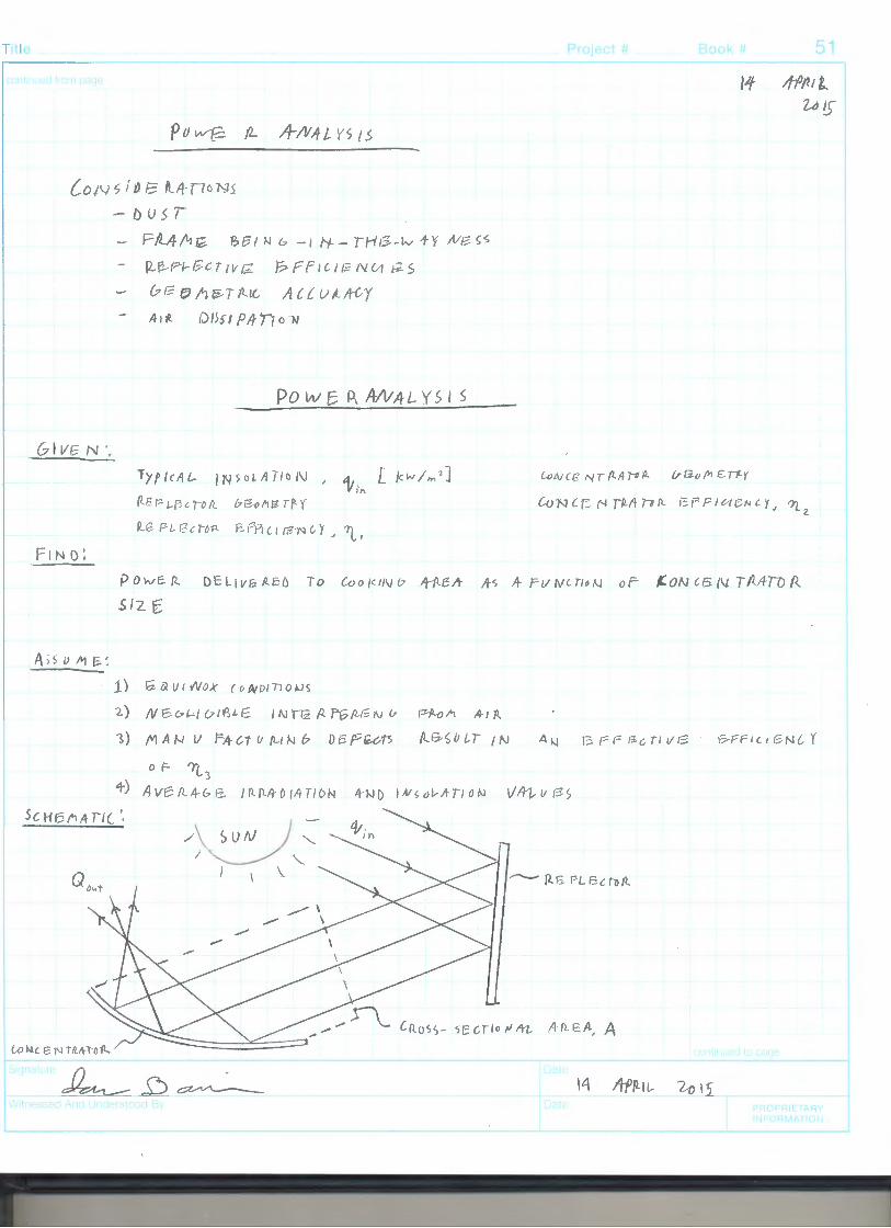
T tie
LoN s / tJ. 8 fl4170Ns
GI Vb N ..
- Du 5 r FM/11,;. "&£31 N b -1 f-1- - THt3-w +'f /VJ?- ~s
P.,B-P-1-Gcr1vr;. l?Pf1l11;NV11-2S
& I~ (;) A fi, T /l.I(, A c { u tt fr{, y A-ill Oi>n P/ff1or.i
Pow~ P\ A-NA-Ly s 1 s
I N s o U! / 1 o 1\1 , a, [ Jc w I,,,, 2 ]
V i',.. (/.Er- 1-B c 'rO /l b G-o fl fl rJ '{
R.G PL. I? c: lb'fl- P--11'1 l I ~1"1 6Y ?) , l, I
Project# Book
lo N c r= H Tflfl 10 fl 1~ ;= F 10 BN l r, llo '(.,2.
Powe. fl- DcL1vizP..El) To Coo/<1/Vb "HlBA- A-s A- P11rvcm1'.I oF ~ON l6{1..L Tfi..fl:IDR
..s12 E
1) Gav1Nox cowotnokls
2) N'6v'-'/u1'()LE. 11\JTTz AfGp.J;;1v v Pfi-ol'1 .41R
51
1) MAN V rA-ct u {LIN b Df5.Pte.ot5 (l&S/JlT /N 1?-F FI l 1 /'3 N l Y
0 F- 113 4) AvBIZ4-&1:Z.. /Rf\-!rDIA-TION 4-ND 1A1~01r1rno"'1 Vftt,v P-S
5cH6tiA II(',
/\ )UN j :: .._ /~ "--
} \
-
-----i
\l\ PR TA y
J JR AT

o? . 'I t;1_
IS /rp{l/1.. 11) 15
Pow&P- A-N.4Ln1~ - ~NT"D
4NALY51{
Q0'1+ A i 1t;,, 'YL, ~2 11~
Foll.
P--o.t fol(_
(;,l !fSS /111(l/1"1Jfl 'IL, = qs ~ flc Fl- /3l r IVG
(.,a;...i~TAUl//o /\J
A- LI/ f'1 I l\J v 11'1 I 'lL 2. = :? 0 % SP-fl-vfl..1 t'fL3 :::: SO 9-"o
00"1t ::= tflt)') ( • q) C • ~) (. 3) 1 A
Oo"t-:::: ·4-6o<ti tti;h A
pap_ s l 0.) 1f 1'n ".'.:::: 4-. i 7 kWh /ni 2/ J()c1
a. = 1-. g 7 kW)" /;,,i/ ~ (i+ ~ ) Y,~
4,.1'\ - o. 203 kW/mz
)o.;
o.,,.i·:::: ( +D6 ?>)( .2,o) 'd% 'L) A
Qo:.+== (0.Dlf1~ /c~,,l.) A
Fo fl .4 Coo/c..UJ b -4- P-i~A- o F fJ' 3 o r:.. w-. _,
t}octt- -
=
Q "~I" -!! D2 i
(9. o q s c; k "'~~ 2) A
r c 3 m) 2.
4 ·.::. t·32.3 k\f\//4 /\ -o~~ /rn
~'o .. t
A= "$:.~_.) kl~~+
~~~
Pro,ect #
1-i; 11-Pfl-ll- 2-o 1r
Boo>< #
(1)
c2)
(s)
(4)
())
PRr ~. E" ARY
IN!-ORMAT!ON

rte
\-0 R. DBs In,& D lo 8 5. 4-() 6 u T
A:::: /.1)4 t"'l 2
o PT i!"V\4'[
A5 s ()fl p // 0 N 5 ~ I) 1\J o I Tl 0~ ~
2) p._ Sc TA N & v LA-
"3) 0 &S r & rv Fo A.
a
5, ; z e o F Th E
R. 6 eL e c.:10 n__
s /_ 0
Project# Book# 53
It 41/LJl- 2-015
i6 AffLIL WI')
PRC '1-1 E l\'iY If\. r.I ,\,1/ I "J

'JC V\ ', , J... J" j >-y
s.s
# )j008
;
-t '-'! % I b .5. '? :::. ~::t /(V 5L'~ )('" 5'1) ~ ::::
~ ~ 11 ::: ~[
..--=
N4 159C/
I
I ,.<
4' l\I ) s. 'b1 00 . :r 41
£ c "-' s -z 'o J ( I(/ s ·1 ) ~1 -"'-
£ ~~ T--:::: 7.1
-><
q so 1%X// x};,
~(]I SNOJ
(} 9(} IS N OJ
51 fJ-z., l l'lld-V 11
e1. L 17S

Tit e Project#
5"4 1~ ltP/41L io rs
/_ I ft- P Ill L 0J i 5
Y4 1"
+1 t~t I 1/1 I~ 'A ~/Vl A->
t .j, ,u J, J, ~
1~· '72----"'
/l = A. e P (, r
x
Book#
( Jt- N r I l-- Ev I~ ti- 1=. f) -.
y
55
= ( p; NJC ~ - s-~ ( -7£:) ,_ C 4t 1 ),7'1r ~)
Fon.. OS~ ,
+ I 4
A..r:z l. 6 o ii.;/Pt
€ "" 4 S e ~ f o I b 5-/4 3 O>P,
l>
l,tJ IS '>oPRI TA f
FlRMAT•ll\

r, 'Vv'H:J J't Vi ltJd u
LS..
s 3 ~ N 17 I / 'J JV' • 3 fl 'U .J. -1 "/I/ // ,,
'7'1' /7 S' CJ
/73 bl(& '.~ U/ bl(f r ~.,,,W
J =-}
--~#~v~,~~~z~·~~;.......:;;;......-~~f--'
b:r 4_::
~._:_11':LI~[ rlL-Ll _:_c·~~-L_ __ ~/,~,~~1'1-) h~'i~~::., ')u'1*~~#~,];J.~ ,~· ~~+~0 9y'I;)--------
1I B 9;
(ti I I '-,{ f) 7 , •1, CJ I s ~ (1
# )j008
~lf12 11?1d/I IZ .s .s
e1l .L 9S

Title Pro1ec~ #
/l'iQTfz/, IU?s u LIS D o ;V T 11-C&ou f\J I r-vfl._
W f2,{ & HT o F fz il- f L 8-c;r I V 8'.- /11 /t-1 1_
Book# 57
---' 63
L>Rt PP TA <Y ,. FURTv'ATI f',
---'-----
-.

rte
-c,,
w
fl NI)',
1.
(~fl.. fl Uf;.
pv4/TloN
..f P:t 6fi el' A-f'
Project#
0 65 I & N / 5il.lf~(TLD..N
~f_ £2 VI fl F- 0 IV (Ui/?lEcnrz. I "1
( wun ~ T CA 5 /; J lr'N A-Ur; l- E fl ll-'11 o N
~ fi, ~~ J 1'\ h} p P--0-P v «E s A- T£ 1 /2 O U~.U4'-
2, fa ~ofL O)lf,O ~ tA3/h' G B 8.t-fl 1 N b L~ /\.• ,.... 0.2
~. N&&1.- i l71P.t1::.
2_,T;:;. I rJ.
i:h - T f ;:: I <:}..,
r::-/L1 {Ti ON fl r ),-o'vvffi._ /)!?A-fl. I "1 &
f'111uoP.. f\SSer~8L y ( INU.JNCl))
--T
['
z 3 AP /LIL
[ '
Book# 59
23 ltPfLtt u 15
l/Vl'fJi£ fl_ 5oi-Si1lE
vF 1 n_pf"\
~l~il'lbP, ~ '(J1fr;_j'('I
01't.-
60
~nO' < E ARY N (' 1'v1A O'l

60 Tit e Proiect # ---- -
S"tt
2 '4 /tpp.11.- i 0 15 Tfl!rlll //-.) b ~' tl]7J~ /)/}<. / b N / > /ZJ:,,/i:c,, TliJ llJ - c (, 1'iT' 1)
I~ i.VHl/ Nb FI? fJ ·, ------
~ F := 0 f)
~ 0::: RA - m9 Sine
P-4 ;::. rri~ sfh e
'S_;t\ fJ ~o O ~ ·--am.'.} c;,o., Q r ~ {,;t·f b)
FN ·::: (fa vv t...os o Mb
/,/.;
f - - \II' .1 N - t,U-b tft:. "'
~o.) rf -= fa r, t).'~b \r1/ UY, e
F 11..J o cl JC: 1 p_P~ ~f~}-2 SU ~~~\,,,,\,
Z F-t;; 0
D :: R t -r F,., ·- '"" 8 cos e R-t ::. i'l'IJ c,aj e _ ~.
"'-:;, I nerr:110N/l'IN. ( 2.. ·n-- rtA),). ( ~ ~) L. 5.f,<", '.1-~ , oD ~u
cL--::::: 2 '/Y -j / _o
)--11'% ·, $
-L--= O, o S z. + r(,{tl/5 ·2
fl"' D T~h
Tsh - Ir, ::::. I cf.-
Ts,,=- fcLt-/'F
~<;?CV'/~ i-t AP ll.1t.- 7_.,c 15
Book#
6 l
.JPP, T/l y ,.

Tit e
cc I l
So
60
I-::::. 77 . 37 x10 3 fbjyd}il
~ ~- D. l· 'i J h - AS ' c. I ' T ;::. --:z:- - ,VJ I "
t:L = b \ftf .~ I z t: IL J-~
/ ) ~ . ,)
t7' =: .5"t . (1
[: 2. 0. D
I. 6 7 --
N ~xr ' c x PLofLE.
t, > lK 61
~ 0 ,~ 'd 9 f ffl I I ) .
+

rit le Project# Book n 63
C"l1 J n"T 11 5° 7
(o NI 1 tvv 1 N & v s rz. o F 5 Y At M f3, If.- Y) v > ~ TH rz F o ~iv 1 IV b ~ () o~ --
@)"1 i !'l-c Y/ 9 lto',
(Y It OSf!;
@ Plri~ boli ~d
Ft 1'i D
w
w ( ~))
6EI w ( ~) ~
JI f;, .J:_
w l~)t 3 e-r
. 2,z~
[)a
l~· w- y
i L
. . r 1
t ' d t c 6f
'l-6 lrf>fl.I i- 2 o I !i "R JPRI TA °"friRMATl<ll\
---- -- ---- -----'----------'

--i
I ' \tV'J>:!') <'\I I
~8\t 3 'Otld 'U +
SIOZ, 111.ldV 9'Z
# )j008 ll 1 79

NClli\fv'H:IC' IN ).1-'\fi l::ld0' •
L9 EJ anu1 1
# )j008 # pefOJd
I +
s I),,\ iilNV 51XV ~N/71?-tl'd.l ,l7/-V0 ~'l1L 99

n e O A-IL Y rn..Avtc.t kl & A X/5 BFN o 1 N & A-Nlf L Ys1 ~
er' rpa 6'
ltX15 ll > A-
< 6 b[I
Project# Book#
A_¢'·'"'" ~,6 1.6 1'"
67
p 6 )( 6Liz-J ( L -z .... b 1 - x<)
i:=1 ND
Ft N l)
--Vv
w == IN n e,, == ep,?c.- A(. L = 4~ i n ( = s-oo lbJ./f-1-3
51 "1'/j
tt= b '.:: 2"'t i ti
r - ? b !:- - J 0 )(1 0 f 51
:r:.
( L' - b?. - b '-)
- --------------~ p~~~ 2..q ,fp f!I L
'1 lPP AR'! 'J <lP Af

68 T•lt DA-IL Y T /),, /I-CIC/ N G Axi s Be'l--IOIN & A-N/-TLY .s15 P•oect" Book# -- - ------- - -
2. "t. frP Jt.l L 1-o I !;
PtND p
Fi nd
p = wri. ~11,., h•. lo~ e :=: (k 5" J b 5- ) l us ( > t. ~ ' )
P .:::::. 7o.o l'i·f
J(x=b) 7. , )
('_ - IN b (L1-1.L b"--rb'3) -~ (L1.- 2), ~- 2AEI ~ 6J..5.I.
= - __ (.2;1~ ~;..-)('2.4)..() -R4s ;,iJ°3-z(43;·)')x24 •'i )l f- { z4.1o})1 Z.4(~0,1g1•' ~n·)(.l6 q 1 ,'r.1)
- ( 7o.o ~) (i.4v,) 4 [ ( 43 ¢}" - 4 C24~JJ
6 (+~ ;n)(Jo ;.;((/i ~~) (,3 aqq 1/)
7 -'3 . - I . z. C> )({ () I lo'\ -3 - / 7 1 31 q XJ/ 0 I I')
[ S -: - O. DI q i]
* fi/o/6 ', +~ovE. CA uvL-fr/lD N Fltll- ) Tl> !Trrov.1\JT
f2-o1t IN (, L 1 i\1 r:o.) it- 1\J o 1)
Jl1 lJ~ (01-.i)µVA'il viZ :\ \.'V\,1,\
J J// j>
L-/ ~\,0vj/
~
I s I= - w,, p-e .x ( L' - 2L ~ l t- ~}) c 0 s 9 -Z-46 I
~cP ' ~
P"° 5 9 bx 6 LE. I
( L 'L_ b 1._ ~ 1 )
?.-it A-P/l. 1t,_ 2-<J 15
~
t- t- 1...' 'R 1 TARY N ' Vl\rlC "l

Appendix H: Gantt Chart

ID Task Mode
Task Name Duration Start Finish
1 WINTER 104 days Thu 1/15/15 Wed 4/29/15
2 Letter of Introduction 3 hrs Thu 1/15/15 Thu 1/15/15
3 Project Proposal 17 days Fri 1/16/15 Mon 2/2/15
4 Background Research 17 days Fri 1/16/15 Mon 2/2/15
5 Patent Search 17 days Fri 1/16/15 Mon 2/2/15
6 Problem Definition 1 day Sun 2/1/15 Mon 2/2/15
7 Preliminary Design Report 31.33 days Mon 2/2/15 Thu 3/5/15
8 Brainstorming and Concept Ideation 1 day Mon 2/2/15 Tue 2/3/15
9 Prototyping Round 1 1 day Tue 2/10/15 Wed 2/11/15
10 Go No‐Go Chart 1 day Tue 2/17/15 Wed 2/18/15
11 Pugh Matrix 5 days Thu 2/12/15 Tue 2/17/15
12 Decision Matrix 7 days Wed 2/18/15 Wed 2/25/15
13 Design Selection 0 days Sat 2/28/15 Sat 2/28/15
14 Gantt Chart 1 day Tue 2/24/15 Wed 2/25/15
15 Sketches of Top Concepts 5 days Sat 2/28/15 Thu 3/5/15
16 Preliminary 3D Model of Top Design 5 days Sat 2/28/15 Thu 3/5/15
17 Preliminary Design Review in Class 0 days Thu 3/5/15 Thu 3/5/15
18 Preliminary Design Review with Pete 0 days Wed 3/11/15 Wed 3/11/15
19 FMEA 51 days Mon 3/9/15 Wed 4/29/15
20 DV Planning 3 days Mon 3/9/15 Thu 3/12/15
21 Analysis Planning 1 day Thu 1/15/15 Fri 1/16/15
22 SPRING 78 days Mon 3/30/15 Tue 6/16/15
23 Critical Design Report 32 days Mon 3/30/15 Fri 5/1/15
2/28
3/5
3/11
T S W S T M F T S W S T M F T S W SDec 21, '14 Feb 15, '15 Apr 12, '15 Jun 7, '15 Aug 2, '15 Sep 27, '15 Nov 22, '15 Jan 17, '16
Task
Split
Milestone
Summary
Project Summary
Inactive Task
Inactive Milestone
Inactive Summary
Manual Task
Duration-only
Manual Summary Rollup
Manual Summary
Start-only
Finish-only
External Tasks
External Milestone
Deadline
Progress
Manual Progress
Page 1
Project: Team Helios GanttDate: Thu 12/3/15

ID Task Mode
Task Name Duration Start Finish
24 Critical Design Review with Pete 0 days Fri 5/8/15 Fri 5/8/15
25 Progress Report 2 days Tue 6/2/15 Thu 6/4/15
26 Prototyping 16 days Sun 4/5/15 Tue 4/21/15
27 Choose build style(s) 3 hrs Tue 4/7/15 Tue 4/7/15
28 Component drawings 1 day Fri 4/10/15 Sat 4/11/15
29 Dish sweep template 1 hr Fri 4/10/15 Fri 4/10/15
30 Wooden lath 0.5 hrs Fri 4/10/15 Fri 4/10/15
31 Reflective surface section patterns 1 hr Fri 4/10/15 Fri 4/10/15
32 Sweep Jig 2.5 hrs Fri 4/10/15 Fri 4/10/15
33 Fabrication 16 days Sun 4/5/15 Tue 4/21/15
34 Dish sweep template 2 hrs Sun 4/5/15 Sun 4/5/15
35 Wooden lath 1 hr Fri 4/17/15 Fri 4/17/15
36 Reflective surface section patterns 2 hrs Fri 4/17/15 Fri 4/17/15
37 Sweep Jig 1.5 hrs Sun 4/19/15 Sun 4/19/15
38 Assembly 1 hr Sun 4/19/15 Sun 4/19/15
39 Analysis 4 days Tue 4/7/15 Sat 4/11/15
40 Power delivered (working backward) 1 day Tue 4/7/15 Wed 4/8/15
41 Concentrator Size 1 day Wed 4/8/15 Thu 4/9/15
42 Reflector Size 1 day Thu 4/9/15 Fri 4/10/15
43 Axis Bending 1 day Fri 4/10/15 Sat 4/11/15
44 Motor Torque/Speed 1 day Fri 4/10/15 Sat 4/11/15
45 Drawings 22 days Mon 5/25/15 Tue 6/16/15
46 Concentrator Assembly 2 wks Tue 6/2/15 Tue 6/16/15
5/8T S W S T M F T S W S T M F T S W SDec 21, '14 Feb 15, '15 Apr 12, '15 Jun 7, '15 Aug 2, '15 Sep 27, '15 Nov 22, '15 Jan 17, '16
Task
Split
Milestone
Summary
Project Summary
Inactive Task
Inactive Milestone
Inactive Summary
Manual Task
Duration-only
Manual Summary Rollup
Manual Summary
Start-only
Finish-only
External Tasks
External Milestone
Deadline
Progress
Manual Progress
Page 2
Project: Team Helios GanttDate: Thu 12/3/15
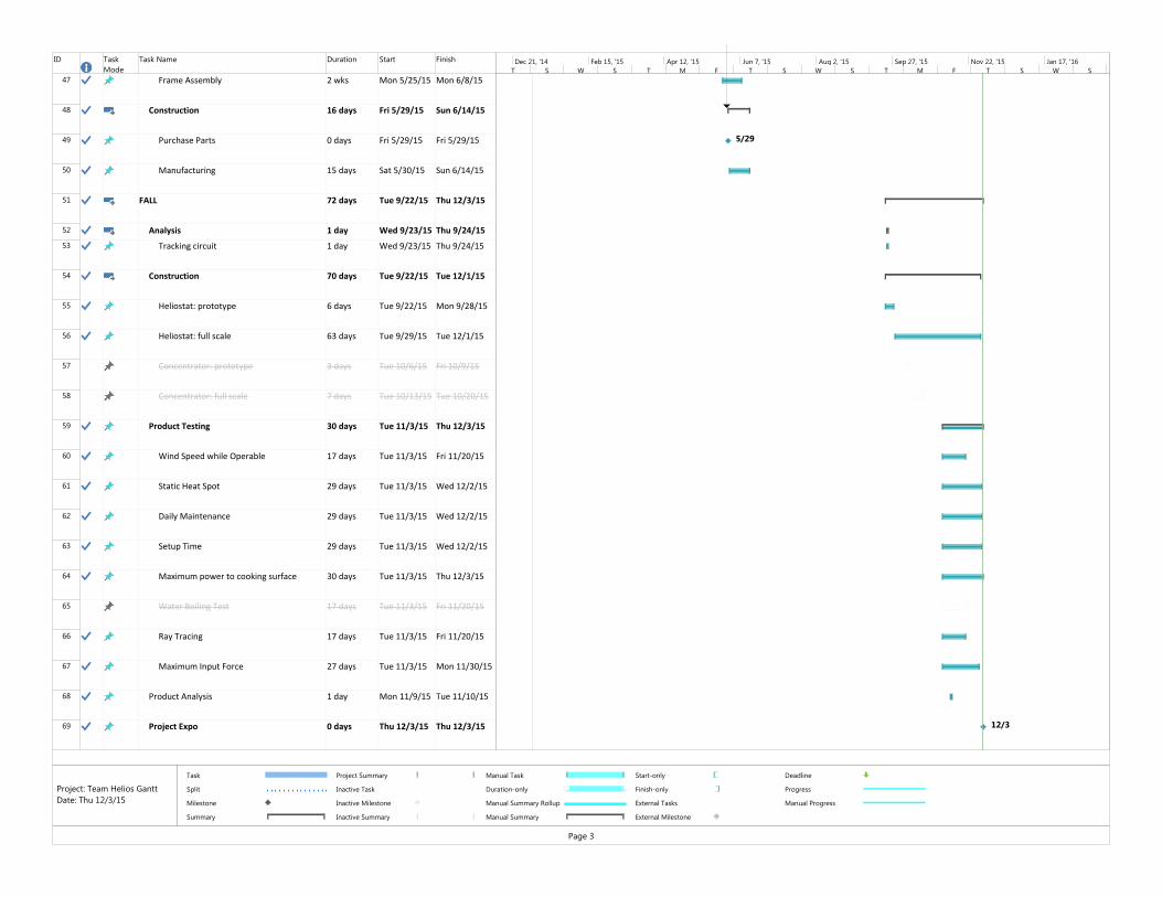
ID Task Mode
Task Name Duration Start Finish
47 Frame Assembly 2 wks Mon 5/25/15 Mon 6/8/15
48 Construction 16 days Fri 5/29/15 Sun 6/14/15
49 Purchase Parts 0 days Fri 5/29/15 Fri 5/29/15
50 Manufacturing 15 days Sat 5/30/15 Sun 6/14/15
51 FALL 72 days Tue 9/22/15 Thu 12/3/15
52 Analysis 1 day Wed 9/23/15 Thu 9/24/15
53 Tracking circuit 1 day Wed 9/23/15 Thu 9/24/15
54 Construction 70 days Tue 9/22/15 Tue 12/1/15
55 Heliostat: prototype 6 days Tue 9/22/15 Mon 9/28/15
56 Heliostat: full scale 63 days Tue 9/29/15 Tue 12/1/15
57 Concentrator: prototype 3 days Tue 10/6/15 Fri 10/9/15
58 Concentrator: full scale 7 days Tue 10/13/15 Tue 10/20/15
59 Product Testing 30 days Tue 11/3/15 Thu 12/3/15
60 Wind Speed while Operable 17 days Tue 11/3/15 Fri 11/20/15
61 Static Heat Spot 29 days Tue 11/3/15 Wed 12/2/15
62 Daily Maintenance 29 days Tue 11/3/15 Wed 12/2/15
63 Setup Time 29 days Tue 11/3/15 Wed 12/2/15
64 Maximum power to cooking surface 30 days Tue 11/3/15 Thu 12/3/15
65 Water Boiling Test 17 days Tue 11/3/15 Fri 11/20/15
66 Ray Tracing 17 days Tue 11/3/15 Fri 11/20/15
67 Maximum Input Force 27 days Tue 11/3/15 Mon 11/30/15
68 Product Analysis 1 day Mon 11/9/15 Tue 11/10/15
69 Project Expo 0 days Thu 12/3/15 Thu 12/3/15
5/29
12/3
T S W S T M F T S W S T M F T S W SDec 21, '14 Feb 15, '15 Apr 12, '15 Jun 7, '15 Aug 2, '15 Sep 27, '15 Nov 22, '15 Jan 17, '16
Task
Split
Milestone
Summary
Project Summary
Inactive Task
Inactive Milestone
Inactive Summary
Manual Task
Duration-only
Manual Summary Rollup
Manual Summary
Start-only
Finish-only
External Tasks
External Milestone
Deadline
Progress
Manual Progress
Page 3
Project: Team Helios GanttDate: Thu 12/3/15

ID Task Mode
Task Name Duration Start Finish
70 Print Poster 0 days Mon 11/30/15Mon 11/30/15
71 Final Design Report 25 days Fri 11/6/15 Tue 12/1/15
72 Report Sections 25 days Fri 11/6/15 Tue 12/1/15
73 Title Page, Table of Contents, List of tables, figures, nomenclature, Executive Summary
25 days Fri 11/6/15 Tue 12/1/15
74 Introduction 25 days Fri 11/6/15 Tue 12/1/15
75 Background 25 days Fri 11/6/15 Tue 12/1/15
76 Design Development 25 days Fri 11/6/15 Tue 12/1/15
77 Design Specifications 25 days Fri 11/6/15 Tue 12/1/15
78 Product Realization 25 days Fri 11/6/15 Tue 12/1/15
79 Testing 25 days Fri 11/6/15 Tue 12/1/15
80 Conclusions 25 days Fri 11/6/15 Tue 12/1/15
81 Appendices 25 days Fri 11/6/15 Tue 12/1/15
82 QFD, Decision matrices 25 days Fri 11/6/15 Tue 12/1/15
83 Final Drawings 25 days Fri 11/6/15 Tue 12/1/15
84 List of Vendors 25 days Fri 11/6/15 Tue 12/1/15
85 Vendor Data Sheets 25 days Fri 11/6/15 Tue 12/1/15
86 Detailed Analysis 25 days Fri 11/6/15 Tue 12/1/15
87 Gantt Chart 25 days Fri 11/6/15 Tue 12/1/15
88 Print and bind sponsor and advisor copies
89 Upload PDF to library, obtain receipt
11/30T S W S T M F T S W S T M F T S W SDec 21, '14 Feb 15, '15 Apr 12, '15 Jun 7, '15 Aug 2, '15 Sep 27, '15 Nov 22, '15 Jan 17, '16
Task
Split
Milestone
Summary
Project Summary
Inactive Task
Inactive Milestone
Inactive Summary
Manual Task
Duration-only
Manual Summary Rollup
Manual Summary
Start-only
Finish-only
External Tasks
External Milestone
Deadline
Progress
Manual Progress
Page 4
Project: Team Helios GanttDate: Thu 12/3/15

Appendix I: Potential Failure Modes and Effects Analysis

PotentialFailure Mode and Effect Analysis
(Design FMEA) FMEA Number:Page 1 of 7
System: Concentrator Design Responsibility: Ian DavisonSubsystem: Frame Prepared By (Orig.): Ian DavisonComponent: - FMEA Date (Orig.) 3/11/2015
Revised By: Ian DavisonRevision Date: 12/2/2015 (Rev.) A
Action Results
Actions TakenSev
Occur
Crit
3 Thermal warping 3 9 None - 0
3Warping under the weight of collected rainwater
7 21 Integrate drainage holes in concentrator
I. Davison5 Oct. 2015 0
2 Thermal warping 3 6 None - 0
2Warping under the weight of collected rainwater
6 12 Integrate drainage holes in concentrator
I. Davison5 Oct. 2015 None 2 6 12
3 Foundation settling 4 12
Add a feature to allow for calibration of the frame position relative to the foundation
I. Davison5 Oct. 2015 None 3 4 12
3 Frame corrosion 3 9 Paint frame I. Davison5 Oct. 2015
Non-corrosive material selected for frame 3 2 6
2 Foundation settling 7 14
Add a feature to allow for calibration of the frame position relative to the foundation
I. Davison5 Oct. 2015 None 2 7 14
2 Frame corrosion 2 4 Paint frame I. Davison5 Oct. 2015
Non-corrosive material selected for frame 2 1 2
Optical system alignment failure 7 Frame picked up by
wind 5 35 Design braces for high wind scenarios
I. Davison5 Oct. 2015
Frame to be installed in-ground 7 2 14
0 0
Recommended Action(s)
Responsibility & Target
Completion Date
Item / Function Potential Failure Mode Potential Effect(s) of
Failure
Sev
Potential Cause(s) / Mechanism(s) of
Failure
Occur
Efficiency drop
Focal point translation
Rigid body motionPrevent rigid
body motion of concentrator
Crit
Efficiency drop
Focal point translation
Shape change
Maintain proper shape for reflective material

PotentialFailure Mode and Effect Analysis
(Design FMEA) FMEA Number:Page 2 of 7
System: Concentrator Design Responsibility: Ian DavisonSubsystem: Concentrator Surface Prepared By (Orig.): Ian DavisonComponent: FMEA Date (Orig.) 3/11/2015
Revised By: Ian DavisonRevision Date: 12/2/2015 (Rev.) A
Action Results
Actions TakenSev
Occur
Crit
2 Water weight 7 14 Integrate drainage holes in concentrator surface
I. Davison5 Oct. 2015 None 2 7 14
2Material contraction
7 14Choose material with low coeficient of thermal expansion
I. Davison29 Oct. 2015 None 2 7 14
1 Thermal deformation 10 10Choose material with low coeficient of thermal expansion
I. Davison29 Oct. 2015 None 1 10 10
3 Water weight 7 21 Integrate drainage holes in concentrator surface
I. Davison5 Oct. 2015 None 3 7 21
3Material contraction
6 18Choose material with low coeficient of thermal expansion
I. Davison29 Oct. 2015 None 3 6 18
3 Thermal deformation 6 18Choose material with low coeficient of thermal expansion
I. Davison29 Oct. 2015 None 3 6 18
Wrong shape Low efficiency 6 Improper construction 9 54
Experiment with different construction techniques to learn most accurate methods. Consult a manufacturing engineer.
I. Davison30 May 2015
Experimented with multiple construction techniques and selected the most reliable
6 7 42
5 Wind-blown debris, dust 8 40 Advise users to protect
surface when not in useI. Davison5 Oct. 2015
Covered surface when not in use 5 4 20
5 Animal intrusion 6 30 Advise users to protect surface when not in use
I. Davison5 Oct. 2015
Covered surface when not in use 5 4 20
6 Wind-blown debris, dust 10 60 Recommend regular
cleaningI. Davison5 Oct. 2015
Wiped down surface as needed 6 5 30
4 Bird poop 9 36 Recommend regular cleaning
I. Davison5 Oct. 2015
None. Bird poop likelihood observed to be very low
4 1 4
Burn someone 9 Inadeqaute safeguards 8 72 None I. Davison1 Dec. 2015
Maximum power is physically not high enough to cause burns
9 3 27
Blind someone 9 Inadeqaute safeguards 8 72 Require eye protection while in operation
I. Davison23 Nov. 2015
Sunglasses required of those nearby during operation
9 3 27
0 0
Safeguard user
Recommended Action(s)
Responsibility & Target
Completion Date
Item / Function Potential Failure Mode Potential Effect(s) of
Failure
Sev
Potential Cause(s) / Mechanism(s) of
Failure
Occur
Scratched surface
Dirty surface
Focus sunlight
Reflect sunlight (surface finish)
Crit
Focal point translation
Low efficiency
Efficiency Drop
Warping
Low efficiency
Allow user to come to harm

PotentialFailure Mode and Effect Analysis
(Design FMEA) FMEA Number:Page 3 of 7
System: Primary Reflector Design Responsibility: Devin MastSubsystem: Frame Prepared By (Orig.): Ian DavisonComponent: - FMEA Date (Orig.) 3/11/2015
Revised By: Ian DavisonRevision Date: 12/2/2015 (Rev.) A
Action Results
Actions TakenSev
Occur
Crit
8 Strong wind loads 2 16Confirm bolt size provides FS of 2 for worst case wind load
D. Mast5 Oct. 2015
Analysis confirms FS of at least 2 for worst case loading
8 1 8
8 Fatigue 4 32 Upsize bolts D. Mast5 Oct. 2015 Bolts upsized 8 1 8
6 User error 7 42
Etch approximate seasonal slider placement into rotating pipe
D. Mast5 Oct. 2016 None 6 7 42
5 Adjustment creep 5 25 Incorporate additional locking feature
D. Mast5 Oct. 2015
Recommend daily check for proper seasonal positioning
5 1 5
Rigid body translation Low efficiency 5 Ground shifting 3 15 Build on a foundation D. Mast5 Oct. 2015
Reflector frame will be installed in-ground 5 1 5
Warping of frame Low efficiency 1 Thermal deformation 10 10 Select material with low coefficient of thermal
D. Mast 22 Oct. 2015 None 1 10 10
Safeguard user Allow user to come to harm Pinch user 8 Unguarded pinch point 7 56 Paint pinch points red D. Mast
2 Dec. 2015
Joints designed to minimize pinch severity and likelihood
6 5 30
0 0
Maintain rotation axis parallel to
Earth's
Crit
Recommended Action(s)
Responsibility & Target
Completion DateItem / Function Potential Failure Mode Potential Effect(s) of
Failure
Sev
Potential Cause(s) / Mechanism(s) of
Failure
Occur
Cracked/broken reflectorBolt failureSupport Reflector
Improperly calibrated Improper focusSeasonal Adjustment

PotentialFailure Mode and Effect Analysis
(Design FMEA) FMEA Number:Page 4 of 7
System: Primary Reflector Design Responsibility: Devin MastSubsystem: Reflector Prepared By (Orig.): Ian DavisonComponent: - FMEA Date (Orig.) 3/11/2015
Revised By: Ian DavisonRevision Date: 12/2/2015 (Rev.) A
Action Results
Actions TakenSev
Occur
Crit
5 Impact to frame 7 35 Improve frame rigidity D. Mast5 Oct. 2015 Frame reinforced 5 4 20
4 Deformation under its own weight 6 24 Improve frame rigidity D. Mast
5 Oct. 2015 Frame reinforced 4 3 12
5 Strong wind loads 9 45 Improve frame rigidity D. Mast5 Oct. 2015 Frame reinforced 5 7 35
2 Thermal warping 10 20Select material with lower coefficient of thermal expansion
D. Mast5 Oct. 2015 None 2 10 20
5 Wind-blown debris, dust 8 40 Advise users to protect
surface when not in useD. Mast5 Oct. 2015
Users advised to cover surface when not in use
5 5 25
5 Animal intrusion 6 30 Advise users to protect surface when not in use
D. Mast5 Oct. 2015
Animal intrusion determined to be unlikely
5 2 10
6 Wind-blown debris, dust 10 60 Advise users to protect
surface when not in useD. Mast5 Oct. 2015
Users advised to cover surface when not in use
6 5 30
4 Bird poop 9 36 Recommend regular cleaning
D. Mast5 Oct. 2015
None. Bird poop likelihood observed to be very low
4 1 4
0 0
Reflect sunlight parallel to earth
axis
Recommended Action(s)
Responsibility & Target
Completion DateItem / Function Potential Failure Mode Potential Effect(s) of
Failure
Sev
Potential Cause(s) / Mechanism(s) of
Failure
Occur
Crit
Scratched surface Low efficiency
Dirty surface Low efficiency
Low efficiencyAnti-planar deformation

PotentialFailure Mode and Effect Analysis
(Design FMEA) FMEA Number:Page 5 of 7
System: Primary Reflector Design Responsibility: Devin MastSubsystem: Daily Tracking System Prepared By (Orig.): Ian DavisonComponent: Electric Circuit FMEA Date (Orig.) 3/10/2015
Revised By: Ian DavisonRevision Date: 12/2/2015 (Rev.) A
Action Results
Actions TakenSev
Occur
Crit
5 Water intrusion 4 20 Shield motor from condensate
D. Mast5 Oct. 2015 0
4 Loose wiring 4 16 Use manufacturer specified crimps
D. Mast5 Oct. 2016 0
4 Insulation degradation 5 20Tie down cables and wires away from moving parts
D. Mast5 Oct. 2017 0
5 Loose wiring 4 20 Use manufacturer specified crimps
D. Mast5 Oct. 2018 0
5 Insulation degradation 5 25Tie down cables and wires away from moving parts
D. Mast5 Oct. 2019 0
7 Water intrusion 4 28 Enclose motor assembly D. Mast5 Oct. 2020 0
7 Loose wiring 4 28 Use manufacturer specified crimps
D. Mast5 Oct. 2021 0
7 Insulation degradation 5 35Tie down cables and wires away from moving parts
D. Mast5 Oct. 2022 0
7 Loose wiring 4 28 Use manufacturer specified crimps
D. Mast5 Oct. 2023 0
7 Corrosion 3 21 Enclose motor assembly D. Mast5 Oct. 2024 0
7 Loose wiring 4 28 Use manufacturer specified crimps
D. Mast5 Oct. 2025 0
7 Corrosion 3 21 Enclose motor assembly D. Mast5 Oct. 2026 0
7 Water intrusion 2 14 Enclose battery D. Mast5 Oct. 2027 0
7 Loose wiring 3 21 Use manufacturer specified crimps
D. Mast5 Oct. 2028 0
8 Water intrusion 2 16 Enclose battery D. Mast5 Oct. 2029 0
Responsibility & Target
Completion DateItem / Function Potential Failure Mode Potential Effect(s) of
Failure
Sev
Potential Cause(s) / Mechanism(s) of
Failure
Occur
Overheating
SparkShort Circuit
Crit
Recommended Action(s)
Tracking stops
Open Circuit Tracking Stops
Tracking stopsOpen Circuit
Motor
Tracking stops
Chemical Leak
Short Circuit
Battery

PotentialFailure Mode and Effect Analysis
(Design FMEA) FMEA Number:Page 5 of 7
System: Primary Reflector Design Responsibility: Devin MastSubsystem: Daily Tracking System Prepared By (Orig.): Ian DavisonComponent: Electric Circuit FMEA Date (Orig.) 3/10/2015
Revised By: Ian DavisonRevision Date: 12/2/2015 (Rev.) A
Action Results
Actions TakenSev
Occur
Crit
Responsibility & Target
Completion DateItem / Function Potential Failure Mode Potential Effect(s) of
Failure
Sev
Potential Cause(s) / Mechanism(s) of
Failure
Occur
Crit
Recommended Action(s)
8 Loose wiring 2 16 Use manufacturer specified crimps
D. Mast5 Oct. 2030 0
Low voltage Tracking stops 7 Battery aging 3 21 None 0Spring Fracture Inconsistent tracking 6 Excessive cycling 1 6 None 0
6 Excessive pre-load 3 18 Specify maximum pre-load
D. Mast5 Oct. 2015
Spring selected operates well within possible loading scenarios
6 1 6
6 Excessive cycling 1 6 Advise against unecessary cycling
D. Mast5 Oct. 2015
Condemn uneccessary cycling 6 1 6
7 Weathering 6 42 Protect string from weathering
D. Mast5 Oct. 2015
Recommend regular string replacement 7 2 14
7 Mechanical wear 8 56 Choose a more wear-resistant string
D. Mast5 Oct. 2015
Recommend regular string replacement 7 2 14
Slip Inconsistent tracking 6 Mechanical wear 7 42 Choose a more wear-resistant string
D. Mast5 Oct. 2015
Recommend regular string replacement 7 2 14
7 Loose wiring 4 28 Use manufacturer specified crimps
D. Mast5 Oct. 2015
Solder connection points 7 3 21
7 Impact 4 28 Install photovoltaic cell away from impact zones
D. Mast5 Oct. 2015 None 7 4 28
7 Corrosion 3 21 Protect connections from weathering
D. Mast5 Oct. 2015
Weatherproof connections 7 2 14
Low voltage Battery does not charge 7 Faulty panel 2 14 Choose panel with high reliability ratings
D. Mast27 Oct. 2015 None 7 2 14
Safeguard user Harm user Electric shock 8 Loose wiring 2 16 Specify careful insulation measures
D. Mast5 Oct. 2015 None 8 2 16
0 0
Battery does not chargeOpen circuit
String breaks Heliostat swings freely
Photovoltaic panel
Drive train
Spring Set Inconsistent tracking
Chemical Leak
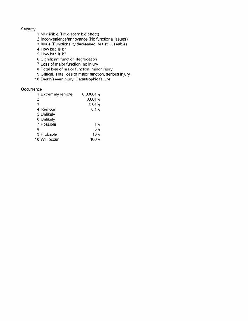
Severity1 Negligible (No discernible effect)2 Inconvenience/annoyance (No functional issues)3 Issue (Functionality decreased, but still useable)4 How bad is it?5 How bad is it?6 Significant function degredation7 Loss of major function, no injury8 Total loss of major function, minor injury9 Critical. Total loss of major function, serious injury
10 Death/sever injury. Catastrophic failure
Occurrence1 Extremely remote 0.00001%2 0.001%3 0.01%4 Remote 0.1%5 Unlikely6 Unlikely7 Possible 1%8 5%9 Probable 10%
10 Will occur 100%

Appendix J: Technical Drawings

FULL BOMITEM NO. PART NUMBER DESCRIPTION QTY.
1 R051 REAR UPRIGHT ASSEMBLY 11.1 R101 REAR UPRIGHT POST 11.2 R011 TOP BENT STEEL PLATE WITH PIPE FITTING 1
1.2.1 T001 TOP BENT STEEL PLATE 11.2.2 T002 HALF PIPE 11.3 R009 SUPPORT BRACKET PLATE 11.4 N/A WASHER FOR .25 INCH 81.5 N/A 1/4-20 NUT 41.6 91286A128 1/4-20 X 5 STEEL BOLT 42 R200 FRONT UPRIGHT ASSEMBLY 1
2.1 R010 BOTTOM BRACKET PLATE 12.2 R007 1.5 STEEL PIPE LEG 22.3 R008 BOTTOM BENT STEEL PLATE 12.4 N/A WASHER FOR .25 INCH 102.5 N/A 1/4-20 NUT 52.6 91286A128 1/4-20 X 2 STEEL BOLT 42.7 R012 MILLED PIVOT BOLT 13 R500 TRACKING STAGE ASSEMBLY 1
3.1 R001 1.5" STEEL ROTATING PIPE 13.2 R004 PLYWOOD SUPPORT FOR HINGE 13.3 R034 PIANO HINGE 23.4 R013 MIRROR ASSEMBLY 1
3.4.1 M001 PLYWOOD BACKING 13.4.2 M002 PLANE MIRROR 43.4.3 M004 1X3 BOARD HORIZONTAL 23.4.4 M005L 1X3 BOARD SHORT, LEFT SIDE 13.4.5 M005R 1X3 BOARD TALL, RIGHT SIDE 13.4.6 90130A012 RUBBER SEALING WASHER 123.4.7 R036 FENDER WASHER 123.4.8 N/A 1/4-20 X 1.5 HEX CAP BOLT 23.4.9 N/A WASHER FOR .25 INCH 63.4.10 N/A 1/4-20 NYLON LOCK NUT 23.4.11 N/A #6 X 3/4 WOOD SCREW 403.4.12 M003 HALF SIZE PLANE MIRROR 1
3.5 R015 SEASONAL ADJUSTMENT SLIDER PIPE 13.5.1 SP001 SLIDER PIPE 13.6 3201T54 PIPE CLAMP 23.7 R903 SUPPORT STRUT 23.8 91375A532 1/4-20 x .125 SETSCREW 23.9 R902 SLIDER PIN 13.10 R800 PHOTOCOMPARATOR ASSEMBLY 1
3.10.1 P001 PHOTOCOMPARATOR BASE 13.10.2 P002 PHOTOCOMPARATOR DIVIDER 13.10.3 N/A PHOTORESISTOR 23.10.4 P004 CONNECTOR BRACKET 13.10.5 N/A #4-40 X .19 WOOD SCREW 63.11 R901 PULLEY 13.12 9640K151 EXTENSION SPRING 13.13 91286A128 1/4-20 X 3 STEEL BOLT 23.14 N/A 3/8"-16 X 2 CAP SCREW 13.15 N/A 1/4-20 NUT 23.16 N/A WASHER FOR .25 INCH 43.17 N/A 1/4-20 X 1.5 HEX CAP BOLT 13.18 N/A 1/4-20 NYLON LOCK NUT 1
4 N/A 3/8"-16 LOCKNUT 15 M400 MOTOR MOUNT ASSEMBLY 1
5.1 a12032000ux0190 12V DC 5 RPM GEARMOTOR 15.2 R020 MOTOR MOUNT 15.3 M503 MOTOR PULLEY 15.4 91400A170 #6-40 X .25 STEEL SCREW 15.5 91735A102 #4-40 X .25 MACHINE SCREW 37 N/A #6 X 3/4 WOOD SCREW 48 R700 TRACKING CIRCUIT 19 R750 BATTERY 1
10 S001 STRING 1

2
3
1
4
8
6
5
7
ITEM NO. PART NUMBER DESCRIPTION QTY.1 R500 TRACKING STAGE ASSEMBLY 12 R051 REAR UPRIGHT ASSEMBLY 13 R200 FRONT UPRIGHT ASSEMBLY 14 M400 MOTOR MOUNT ASSEMBLY 15 R700 TRACKING CIRCUIT 16 R750 BATTERY 17 S001 STRING 18 N/A 3/8"-16 LOCKNUT 19 N/A #6 X 3/4 WOOD SCREW 4
Scale: 1:8Title: REFLECTOR ASSEMBLY
Dwg. #: R000
Drwn. By: DEVIN MASTDate: 12/03/15 Chkd. By: I. DAVISONNxt Asb: N/A
SHEET 2 of 5Lab Section: 03
UNLESS OTHERWISE SPECIFIED:
DIMENSIONS ARE IN INCHES.TOLERANCES:.X±.1.XX±.05.XXX±.005ANGLES±1º

3X 20.00
GROUND LEVEL
50
24.00 3X 8
Scale: 1:12Title: REFLECTOR ASSEMBLY
Dwg. #: R000Drwn. By: I. DAVISON
Date: 12/8/2015 Chkd. By:Nxt Asb: N/ASHEET 3 of 5Lab Section:03

A
B
C
DETAIL ASCALE 1 : 2 DETAIL B
SCALE 1 : 2
DETAIL CSCALE 1 : 4
9 4X
Scale: 1:24Title: REFLECTOR ASSEMBLY
Dwg. #: R000Drwn. By: DEVIN MAST
Date: 12/03/15 Chkd. By: I. DAVISONNxt Asb: N/ASHEET 4 of 5Lab Section: 03

D
DETAIL DSCALE 1 : 2
NOTE THAT THE TWO PULLEYS ARE ALIGNED ONCE THE MOTOR MOUNT IS INSTALLED
Scale: 1:8Title: REFLECTOR ASSEMBLY
Dwg. #: R000Drwn. By: DEVIN MAST
Date: 12/03/15 Chkd. By: I. DAVISONNxt Asb: N/ASHEET 5 of 5Lab Section: 03

A
1
2
3
4
5
6
7
8
9
13
18
14
17
10
11
11
DETAIL ASCALE 1 : 2
12
UNLESS OTHERWISE SPECIFIED:
DIMENSIONS ARE IN INCHES.TOLERANCES:.X±.1.XX±.05.XXX±.005ANGLES±1º
ITEM NO. PART NUMBER DESCRIPTION QTY.1 R001 1.5" STEEL ROTATING PIPE 12 R004 PLYWOOD SUPPORT FOR HINGE 13 R013 MIRROR ASSEMBLY 14 R034 PIANO HINGE 25 R015 SEASONAL ADJUSTMENT SLIDER PIPE 16 R903 SUPPORT STRUT 27 R902 SLIDER PIN 18 R800 PHOTOCOMPARATOR ASSEMBLY 19 R901 PULLEY 110 3201T54 PIPE CLAMP 211 9640K151 EXTENSION SPRING 112 91375A532 1/4-20 x .125 SETSCREW 213 91286A128 1/4-20 X 3 STEEL BOLT 214 N/A 1/4-20 NUT 215 N/A 1/4-20 X 1.5 HEX CAP BOLT 116 N/A 1/4-20 NYLON LOCK NUT 117 N/A 3/8"-16 X 2 CAP SCREW 118 N/A WASHER FOR .25 INCH 4
Dwg. #: R500Lab Section: 03 SHEET 1 of 2
Nxt Asb: R000 Chkd. By: Date: 12/03/15Drwn. By: I. DAVISONTitle: TRACKING STAGE ASSEMBLY
Scale: 1:12

15
16
12
Dwg. #: R500Lab Section: 03 SHEET 2 of 2
Nxt Asb: R000 Chkd. By: Date: 12/03/15Drwn. By: I. DAVISONTitle: TRACKING STAGE ASSEMBLY
Scale: 1:6

26.04
26.56
A
1
2
2
5
3
4
.13
.13
0.150.156
.13
.13
.13
.13
1.00
.56
DETAIL ASCALE 1 : 2
.13
.13
.13
.13
UNLESS OTHERWISE SPECIFIED:
DIMENSIONS ARE IN INCHES.TOLERANCES:.X±.1.XX±.05.XXX±.005ANGLES±1º
ITEM NO. DESCRIPTION LENGTH QTY.1 PIPE, SCH 40, 1.50 DIA. 54 12 PIPE, SCH 40, 1.50 DIA. 16 23 .25 PLATE 14 .25 PLATE 15 .19 PLATE 4.15 26 .25 ROUND STOCK 3.80 1
Dwg. #: R001Lab Section: 03 SHEET 1 of 3
Nxt Asb: R500 Chkd. By:Date: 12/03/15Drwn. By: I. DAVISONTitle: 1.5" STEEL ROTATING PIPE
Scale: 1:2

54.00
23.50
6.50
1 1X
16.00
1.90
2 2X
Dwg. #: R001Lab Section: 03 SHEET 2 of 3
Nxt Asb: R500 Chkd. By: Date: 12/03/15Drwn. By: I. DAVISONTitle: 1.5" STEEL ROTATING PIPE
Scale: 1:16
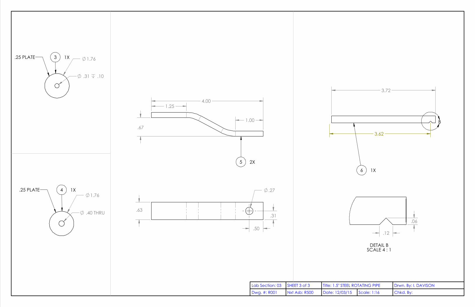
1.76
.31 .10
.25 PLATE 3 1X
1.76
.40 THRU
.25 PLATE 4 1X
.67
4.00 1.25
1.00
5 2X
.63
.27
.50
.31
3.72
3.62
B
6 1X
.06
.12
DETAIL BSCALE 4 : 1
Dwg. #: R001Lab Section: 03 SHEET 3 of 3
Nxt Asb: R500 Chkd. By:Date: 12/03/15Drwn. By: I. DAVISONTitle: 1.5" STEEL ROTATING PIPE
Scale: 1:16

0
1.0
0
3.0
0
5.0
0
7.0
0
9.0
0
11.
00
13.
00
2X
16.0
0
19.
00
21.
00
23.
00
2X
23.5
0
25.
00
27.
00
29.
00
31.
00
2X
8.50
0 14X .48 .75
2X 2.88
2X 5.13
7.25 8.00
32.
00
.50
UNLESS OTHERWISE SPECIFIED:
DIMENSIONS ARE IN INCHES.TOLERANCES:.X±.1.XX±.05.XXX±.005ANGLES±1º
MATERIAL: 1/2 INCH OSBDwg. #: R004Lab Section: 03 SHEET 1 of 1
Nxt Asb: R500 Chkd. By: Date: 12/03/15Drwn. By: I. DAVISONTitle: PLYWOOD SUPPORT FOR HINGE
Scale: 1:4

1 2
3
?
5
UNLESS OTHERWISE SPECIFIED:
DIMENSIONS ARE IN INCHES.TOLERANCES:.X±.1.XX±.05.XXX±.005ANGLES±1º
ITEM NO. PART NUMBER DESCRIPTION QTY.1 M001 PLYWOOD BACKING 12 M002 PLANE MIRROR 43 M003 HALF SIZE PLANE MIRROR 14 M004 1X3 BOARD HORIZONTAL 25 M005L 1X3 BOARD SHORT, LEFT SIDE 16 M005R 1X3 BOARD TALL, RIGHT SIDE 17 R036 FENDER WASHER 128 90130A012 RUBBER SEALING WASHER 129 N/A 1/4-20 X 1.5 HEX CAP BOLT 210 N/A WASHER FOR .25 INCH 611 N/A 1/4-20 NYLON LOCK NUT 212 N/A #6 X 3/4 WOOD SCREW 40
Dwg. #: R013Lab Section: 03 SHEET 1 of 2
Nxt Asb: R500 Chkd. By: Date: 12/03/15Drwn. By: I. DAVISONTitle: MIRROR ASSEMBLY
Scale: 1:12

A
12
7
8
12
4
4
5
1
3
2DETAIL A
SCALE 1 : 1.5
11
10
10
10
9
ITEM NO. PartNo DESCRIPTION QTY.1 M001 PLYWOOD BACKING 12 M002 PLANE MIRROR 43 M003 HALF SIZE PLANE MIRROR 14 M004 1X3 BOARD HORIZONTAL 25 M005L 1X3 BOARD SHORT, LEFT SIDE 16 M005R 1X3 BOARD TALL, RIGHT SIDE 17 R036 FENDER WASHER 128 90130A012 RUBBER SEALING WASHER 129 N/A 1/4-20 X 1.5 HEX CAP BOLT 2
10 N/A 1/4-20 NYLON LOCK NUT 211 N/A WASHER FOR .25 INCH 612 N/A #6 X 3/4 WOOD SCREW 40
Dwg. #: R013Lab Section: 03 Assignment #
Nxt Asb: R500 Chkd. By: Date: 12/03/15Drwn. By: I. DAVISONTitle: MIRROR ASSEMBLY
Scale: 1:8

0
8X
5.63
2X
9.38
2X
15.3
8
2X
21.3
8
2X
27.3
8
2X
33.3
8
2X
39.3
8 8
X 42
.38
48.
00
23.
00
25.
00
0
6X 8.38 2X 10.63
2X 16.63
2X 22.63
2X 28.63
2X 34.63
2X 40.63
2X 46.63
2X 52.63 6X 55.63
64.00
38.00
26.00
.50
UNLESS OTHERWISE SPECIFIED:
DIMENSIONS ARE IN INCHES.TOLERANCES:.X±.1.XX±.05.XXX±.005ANGLES±1º
MATERIAL: 1/2 INCH OSB
Dwg. #: M001Lab Section: 03 SHEET 1 of 1
Nxt Asb: R013 Chkd. By:Date: 12/8/2015Drwn. By: I. DAVISONTitle: PLYWOOD BACKING
Scale: 1:12

48.00
12.00
.25
UNLESS OTHERWISE SPECIFIED:
DIMENSIONS ARE IN INCHES.TOLERANCES:.X±.1.XX±.05.XXX±.005ANGLES±1º
MATERIAL: GLASS MIRROR, SILVERED
Dwg. #: M002Lab Section: 03 SHEET 1 of 1
Nxt Asb: R013 Chkd. By:Date: 12/8/2015Drwn. By: I. DAVISONTitle: PLANE MIRROR
Scale: 1:8

23.00 23.00
2X 12.00
.25
UNLESS OTHERWISE SPECIFIED:
DIMENSIONS ARE IN INCHES.TOLERANCES:.X±.1.XX±.05.XXX±.005ANGLES±1º
MATERIAL: GLASS MIRROR, SILVERED
Dwg. #: M003Lab Section: 03 SHEET 1 of 1
Nxt Asb: R013 Chkd. By:Date: 12/8/2015Drwn. By: I. DAVISONTitle: HALF SIZE PLANE MIRROR
Scale: 1:8

36.00
2.50 .75
UNLESS OTHERWISE SPECIFIED:
DIMENSIONS ARE IN INCHES.TOLERANCES:.X±.1.XX±.05.XXX±.005ANGLES±1º
MATERIAL: PINE
Dwg. #: M004Lab Section: 03 SHEET 1 of 1
Nxt Asb: R013 Chkd. By:Date: 12/8/2015Drwn. By: I. DAVISONTitle: 1X3 BOARD HORIZONTAL
Scale: 1:8

.75
MATERIAL: PINE
2.50
48.00
A
5.00
.27 THRU.75 .13 .90
DETAIL ASCALE 1 : 2
UNLESS OTHERWISE SPECIFIED:
DIMENSIONS ARE IN INCHES.TOLERANCES:.X±.1.XX±.05.XXX±.005ANGLES±1º M005L
Dwg. #: M005LLab Section: 03 SHEET 1 of 1
Nxt Asb: R013 Chkd. By:Date: 12/8/2015Drwn. By: I. DAVISONTitle: 1X3 BOARD SHORT, LEFT SIDE
Scale: 1:8

.75
MATERIAL: PINE 48.00
2.50
21.50
A
B
.27 THRU.75 .13
5.00
.90
DETAIL ASCALE 1 : 2
R3.80
.63
.09
90°
1.38
DETAIL BSCALE 1 : 2
M005RUNLESS OTHERWISE SPECIFIED:
DIMENSIONS ARE IN INCHES.TOLERANCES:.X±.1.XX±.05.XXX±.005ANGLES±1º
Dwg. #: M005RLab Section: 03 SHEET 1 of 1
Nxt Asb: R013 Chkd. By: Date: 12/8/2015Drwn. By: I. DAVISONTitle: 1X3 BOARD TALL, RIGHT SIDE
Scale: 1:8

1.00
.17 MATERIAL: STEEL
.05
UNLESS OTHERWISE SPECIFIED:
DIMENSIONS ARE IN INCHES.TOLERANCES:.X±.1.XX±.05.XXX±.005ANGLES±1º
Dwg. #: R036Lab Section: 03 SHEET 1 of 1
Nxt Asb: R013 Chkd. By:Date: 12/8/2015Drwn. By: I. DAVISONTitle: FENDER WASHER
Scale: 4:1

McMaster PART NO.: 1608A44CUT LENGTH: 14.00
UNLESS OTHERWISE SPECIFIED:
DIMENSIONS ARE IN INCHES.TOLERANCES:.X±.1.XX±.05.XXX±.005ANGLES±1º
Dwg. #: R034Lab Section: 03 SHEET 1 of 1
Nxt Asb: R500 Chkd. By:Date: 12/8/2015Drwn. By: I. DAVISONTitle: PIANO HINGE
Scale: 1:1

2.0
.4
.5
1.0
1.0
.25
1.03
.27
1/4-20 UNC THRU ALL
2.19
1.95
90°
.13 .13
.325 THRU
1.63
UNLESS OTHERWISE SPECIFIED:
DIMENSIONS ARE IN INCHES.TOLERANCES:.X±.1.XX±.05.XXX±.005ANGLES±1º
.13Dwg. #: R015Lab Section: 03 SHEET 1 of 1
Nxt Asb: R500 Chkd. By: I. DAVISONDate: 12/8/2015Drwn. By: DEVIN MASTTitle: SEASONAL ADJUSTMENT SLIDER PIPE
Scale: 1:1

54.60°
19.94
17.75
13.25
A
0.5" SQUARE TUBEMILD STEEL
B
R.50
1.0
.8
.19
.75
DETAIL ASCALE 1 : 1
.25
.25
.27
DETAIL BSCALE 1 : 1
UNLESS OTHERWISE SPECIFIED:
DIMENSIONS ARE IN INCHES.TOLERANCES:.X±.1.XX±.05.XXX±.005ANGLES±1º
DIMENSIONS IN DETAIL VIEWS A AND B ARE TYPICAL OF BOTH ANGLED TABS
Dwg. #: R903Lab Section: 03 SHEET 1 of 1
Nxt Asb: R500 Chkd. By: DEVIN MASTDate: 12/03/15Drwn. By: I. DAVISONTitle: SUPPORT STRUT
Scale: 1:12

1.08
2X .08
.88
.25
UNLESS OTHERWISE SPECIFIED:
DIMENSIONS ARE IN INCHES.TOLERANCES:.X±.1.XX±.05.XXX±.005ANGLES±1º
MATERIAL: MILD STEELDwg. #: R902Lab Section: 03 SHEET 1 of 1
Nxt Asb: R500 Chkd. By: Date: 12/03/15Drwn. By: I. DAVISONTitle: SLIDER PIN
Scale: 4:1

2
1
5
4
3
GLUE PHOTORESISTORS IN PLACE
UNLESS OTHERWISE SPECIFIED:
DIMENSIONS ARE IN INCHES.TOLERANCES:.X±.1.XX±.05.XXX±.005ANGLES±1º
MATERIAL: WOOD
ITEM NO. PART NUMBER DESCRIPTION QTY.1 P001 PHOTOCOMPARATOR BASE 12 P002 PHOTOCOMPARATOR DIVIDER 13 P004 CONNECTOR BRACKET 14 N/A PHOTORESISTOR 25 N/A #4-40 X .19 WOOD SCREW 6
Dwg. #: R800Lab Section: 03 SHEET 1 of 1
Nxt Asb: R500 Chkd. By: Date: 12/03/15Drwn. By: I. DAVISONTitle: PHOTOCOMPARATOR ASSEMBLY
Scale: 1:1

6X .10
0
2X
.70
2X
1.00
2X
1.30
2.0
0
0
.90
2X 1.43
2X 1.58
2.10
3.00
.19
UNLESS OTHERWISE SPECIFIED:
DIMENSIONS ARE IN INCHES.TOLERANCES:.X±.1.XX±.05.XXX±.005ANGLES±1º
MATERIAL: WOOD
Dwg. #: P001Lab Section: 03 SHEET 1 of 1
Nxt Asb: R800 Chkd. By:Date: 12/8/2015Drwn. By: I. DAVISONTitle: PHOTOCOMPARATOR BASE
Scale: 2:1
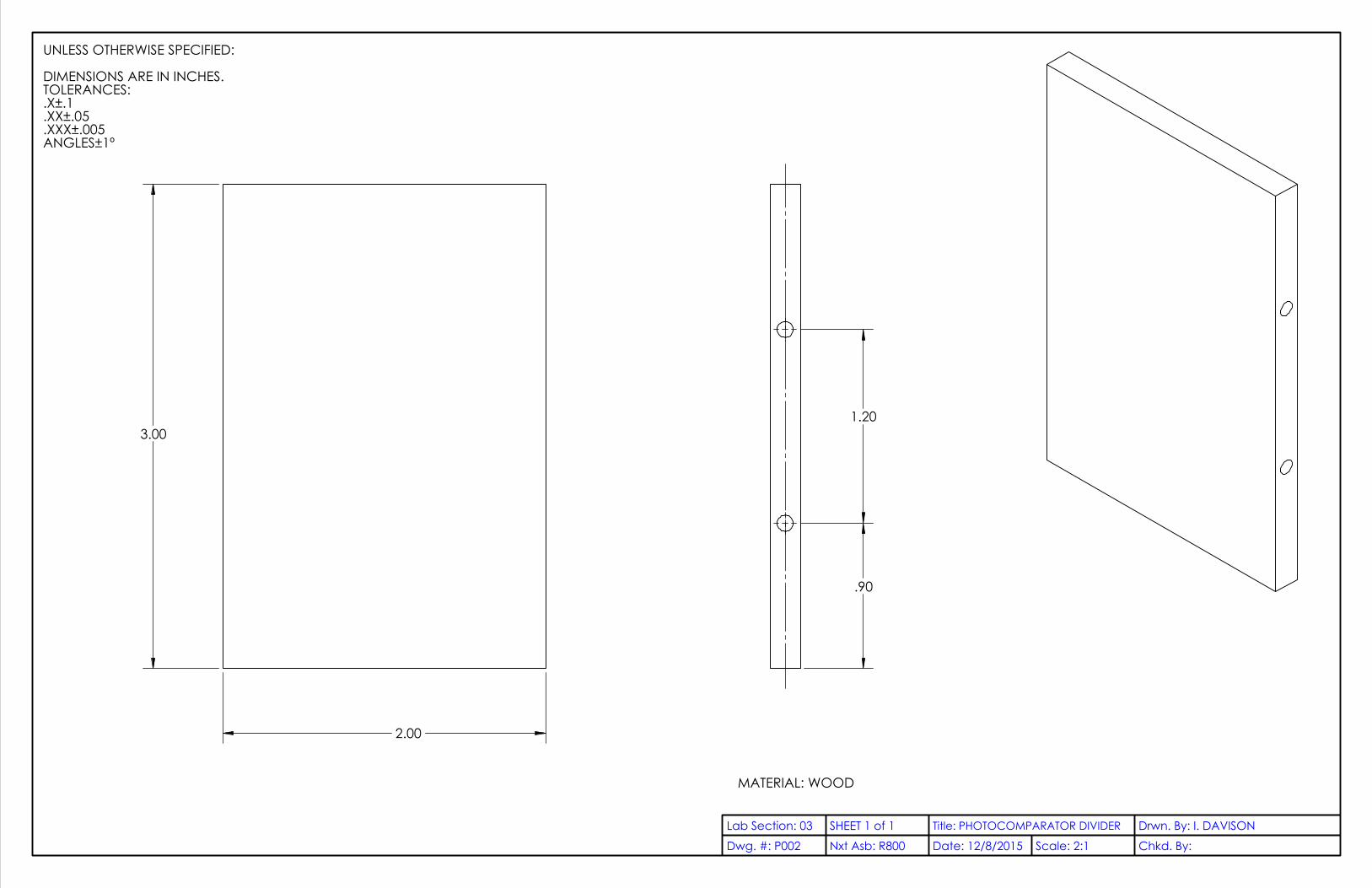
3.00
2.00
1.20
.90
UNLESS OTHERWISE SPECIFIED:
DIMENSIONS ARE IN INCHES.TOLERANCES:.X±.1.XX±.05.XXX±.005ANGLES±1º
MATERIAL: WOOD
Dwg. #: P002Lab Section: 03 SHEET 1 of 1
Nxt Asb: R800 Chkd. By:Date: 12/8/2015Drwn. By: I. DAVISONTitle: PHOTOCOMPARATOR DIVIDER
Scale: 2:1

0
2X .25
2X 1.25
1.50 0
2X
.25
2X
.75
1.0
0
.19
UNLESS OTHERWISE SPECIFIED:
DIMENSIONS ARE IN INCHES.TOLERANCES:.X±.1.XX±.05.XXX±.005ANGLES±1º
Dwg. #: P004Lab Section: 03 SHEET 1 of 1
Nxt Asb: R800 Chkd. By:Date: 12/8/2015Drwn. By: I. DAVISONTitle: CONNECTOR BRACKET
Scale: 4:1

3.50
.26
A
A
R.20
.05 .05
.50
SECTION A-A
UNLESS OTHERWISE SPECIFIED:
DIMENSIONS ARE IN INCHES.TOLERANCES:.X±.1.XX±.05.XXX±.005ANGLES±1º
Dwg. #: R901Lab Section: 03 SHEET 1 of 1
Nxt Asb: R500 Chkd. By: Date: 12/03/15Drwn. By: I. DAVISONTitle: PULLEY
Scale: 2:1

1
2
4
5
63
UNLESS OTHERWISE SPECIFIED:
DIMENSIONS ARE IN INCHES.TOLERANCES:.X±.1.XX±.05.XXX±.005ANGLES±1º
ITEM NO. PART NUMBER DESCRIPTION QTY.1 R101 REAR UPRIGHT POST 12 R011 TOP BENT STEEL PLATE WITH PIPE FITTING 13 R009 SUPPORT BRACKET PLATE 14 91286A128 1/4-20 X 5 STEEL BOLT 45 N/A 1/4-20 NUT 46 N/A WASHER FOR .25 INCH 8
Dwg. #: R051Lab Section: 03 SHEET 1 of 1
Nxt Asb: R000 Chkd. By:Date: 12/03/15Drwn. By: I. DAVISONTitle: REAR UPRIGHT ASSEMBLY
Scale: 1:2

78.00
2X 2.10
2X 1.25
4X .28
2X .89
2X .70
UNLESS OTHERWISE SPECIFIED:
DIMENSIONS ARE IN INCHES.TOLERANCES:.X±.1.XX±.05.XXX±.005ANGLES±1º
MATERIAL: PINE, 4X4 NOMINALFINISH: WEATHERPROOF PAINT,
CAL POLY GREEN
Dwg. #: R101Lab Section: 03 SHEET 1 of 1
Nxt Asb: R051 Chkd. By: Date: 12/03/15Drwn. By: I. DAVISONTitle: REAR UPRIGHT POST
Scale: 1:2

A
A
1
2
B
VIEW A-A
.05 A B.05 M A
A
.25
UNLESS OTHERWISE SPECIFIED:
DIMENSIONS ARE IN INCHES.TOLERANCES:.X±.1.XX±.05.XXX±.005ANGLES±1º
ITEM NO. PART NUMBER DESCRIPTION QTY.1 T001 TOP BENT STEEL PLATE 12 T002 HALF PIPE 1
Dwg. #: R011Lab Section: 03 SHEET 1 of 1
Nxt Asb: R051 Chkd. By: Date: 12/03/15Drwn. By: I. DAVISONTitle: TOP BENT STEEL PLATE WITH PIPE FITTING
Scale: 1:1

4X .28
0
2X
.95
2X
3.05
4.0
0
2X .75
2X 2.00
35°
2.8
2.8
A
A 1.5
2.0
.50
VIEW A-A
UNLESS OTHERWISE SPECIFIED:
DIMENSIONS ARE IN INCHES.TOLERANCES:.X±.1.XX±.05.XXX±.005ANGLES±1º
Dwg. #: T001Lab Section: 03 SHEET 1 of 1
Nxt Asb: R011 Chkd. By: Date: 12/03/15Drwn. By: I. DAVISONTitle: TOP BENT STEEL PLATE
Scale: 1:1

2.25
1.98
2.5
MATERIAL: 2 INCH (NOMINAL) STEEL PIPE
UNLESS OTHERWISE SPECIFIED:
DIMENSIONS ARE IN INCHES.TOLERANCES:.X±.1.XX±.05.XXX±.005ANGLES±1º
Dwg. #: T002Lab Section: 03 SHEET 1 of 1
Nxt Asb: R011 Chkd. By:Date: 12/8/2015Drwn. By: I. DAVISONTitle: HALF PIPE
Scale: 1:1

2X 1.25
2X 2.10 2X .95
2X .50
4.0
2.5
.25
UNLESS OTHERWISE SPECIFIED:
DIMENSIONS ARE IN INCHES.TOLERANCES:.X±.1.XX±.05.XXX±.005ANGLES±1º
MATERIAL: MILD STEEL
Dwg. #: R009Lab Section: 03 SHEET 1 of 1
Nxt Asb: R051 Chkd. By: Date: 12/03/15Drwn. By: I. DAVISONTitle: SUPPORT BRACKET PLATE
Scale: 2:1

3 1
6
7
2
4
5
UNLESS OTHERWISE SPECIFIED:
DIMENSIONS ARE IN INCHES.TOLERANCES:.X±.1.XX±.05.XXX±.005ANGLES±1º
ITEM NO. PART NUMBER DESCRIPTION QTY.1 R007 1.5" SHORT STEEL PIPE LEG 22 R008 BOTTOM BENT STEEL PLATE 13 R010 BOTTOM BRACKET PLATE 14 R012 MILLED PIVOT BOLT 15 91286A128 1/4-20 X 2 STEEL BOLT 46 N/A WASHER FOR .25 INCH 107 N/A 1/4-20 NUT 5
Dwg. #: R200Lab Section: 03 SHEET 1 of 1
Nxt Asb: R000 Chkd. By:Date: 12/03/15Drwn. By: I. DAVISONTitle: FRONT UPRIGHT ASSEMBLY
Scale: 1:8
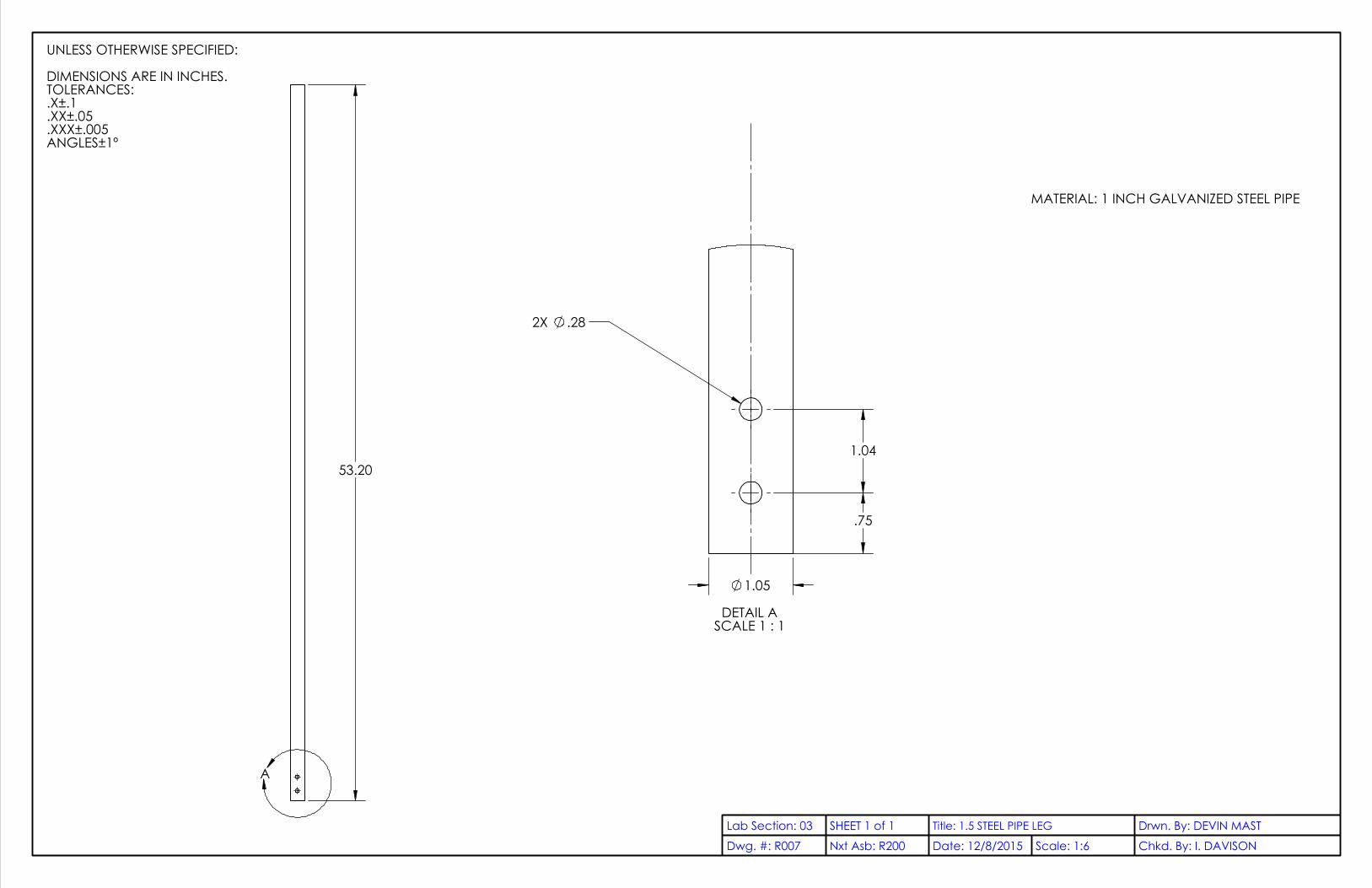
53.20
A
1.05
.75
2X .28
1.04
DETAIL ASCALE 1 : 1
UNLESS OTHERWISE SPECIFIED:
DIMENSIONS ARE IN INCHES.TOLERANCES:.X±.1.XX±.05.XXX±.005ANGLES±1º
MATERIAL: 1 INCH GALVANIZED STEEL PIPE
Dwg. #: R007Lab Section: 03 SHEET 1 of 1
Nxt Asb: R200 Chkd. By: I. DAVISONDate: 12/8/2015Drwn. By: DEVIN MASTTitle: 1.5 STEEL PIPE LEG
Scale: 1:6

4X .28
0
.79
.52
3.2
1
3.4
8
4.0
0
0
2X 1.00
2X 2.00
2.68
2.7
.25
1.9
35°
A
A
1.3
.5
.28
VIEW A-A
UNLESS OTHERWISE SPECIFIED:
DIMENSIONS ARE IN INCHES.TOLERANCES:.X±.1.XX±.05.XXX±.005ANGLES±1º
Dwg. #: R008Lab Section: 03 SHEET 1 of 1
Nxt Asb: R200 Chkd. By: Date: 12/03/15Drwn. By: I. DAVISONTitle: BOTTOM BENT STEEL PLATE
Scale: 1:1

0
.52
.79
3.2
1
3.4
8
4.0
0
2X .50
2X 1.50
2.5
UNLESS OTHERWISE SPECIFIED:
DIMENSIONS ARE IN INCHES.TOLERANCES:.X±.1.XX±.05.XXX±.005ANGLES±1º
MATERIAL: 1/4 INCH SHEETMETAL, MILD STEEL
Dwg. #: R010Lab Section: 03 SHEET 1 of 1
Nxt Asb: R200 Chkd. By: Date: 12/03/15Drwn. By: I. DAVISONTitle: BOTTOM BRACKET PLATE
Scale: 2:1
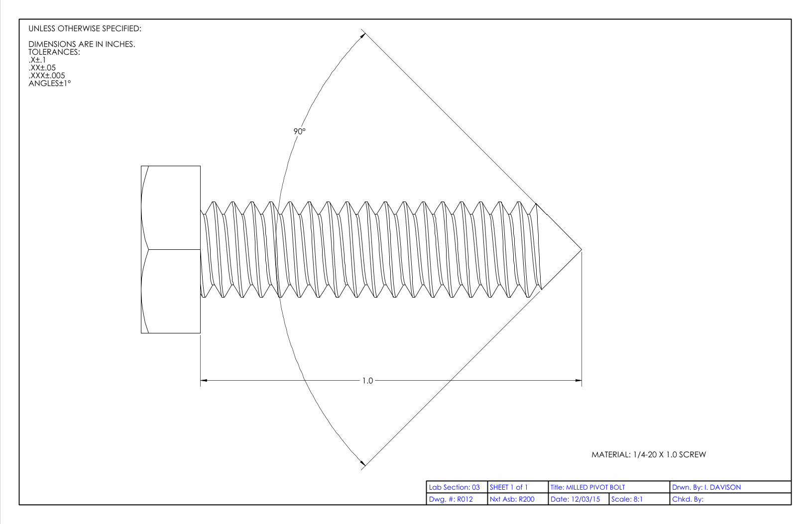
90°
1.0
UNLESS OTHERWISE SPECIFIED:
DIMENSIONS ARE IN INCHES.TOLERANCES:.X±.1.XX±.05.XXX±.005ANGLES±1º
MATERIAL: 1/4-20 X 1.0 SCREW
Dwg. #: R012Lab Section: 03 SHEET 1 of 1
Nxt Asb: R200 Chkd. By: Date: 12/03/15Drwn. By: I. DAVISONTitle: MILLED PIVOT BOLT
Scale: 8:1
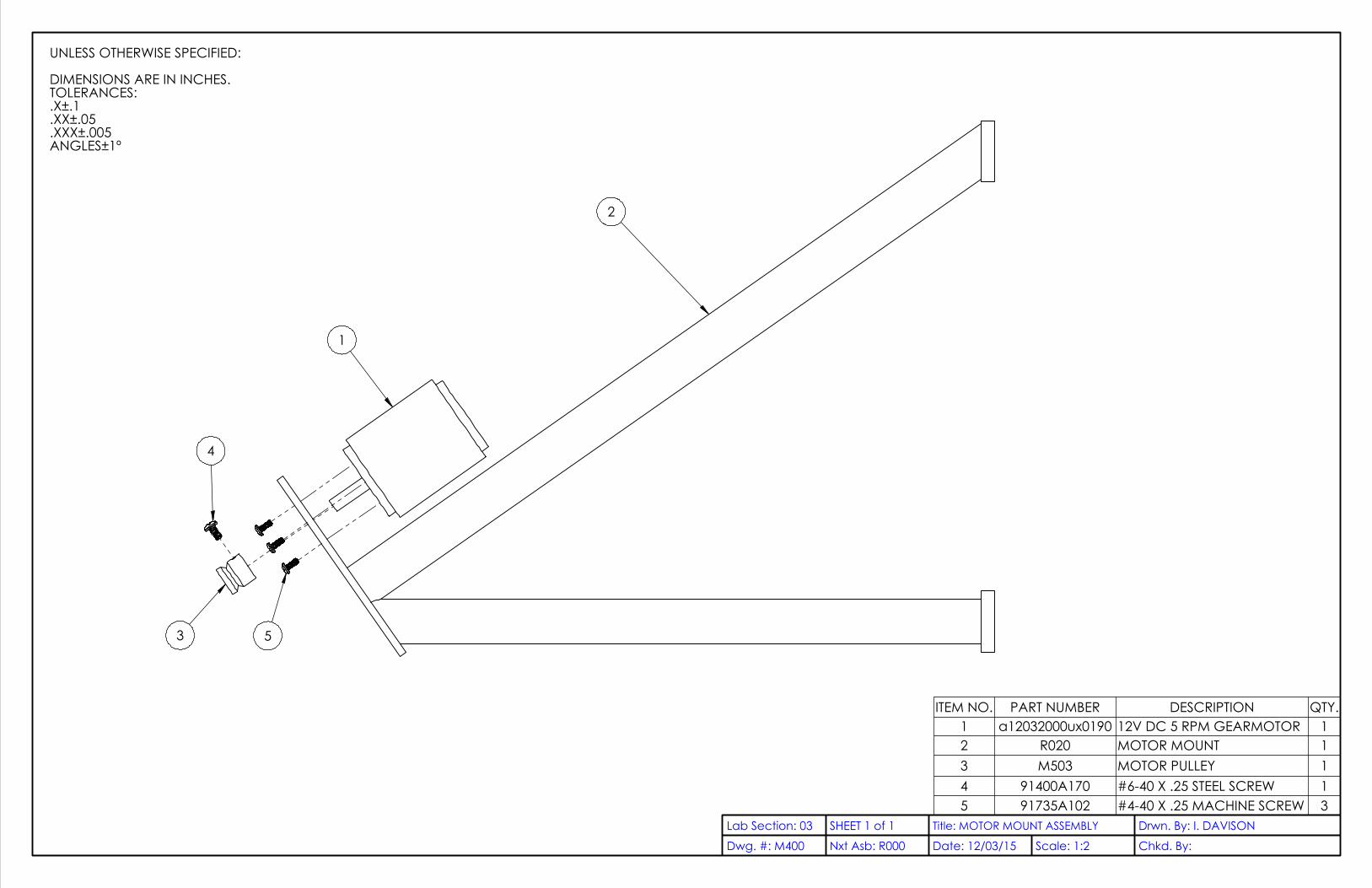
2
1
3 5
4
UNLESS OTHERWISE SPECIFIED:
DIMENSIONS ARE IN INCHES.TOLERANCES:.X±.1.XX±.05.XXX±.005ANGLES±1º
ITEM NO. PART NUMBER DESCRIPTION QTY.1 a12032000ux0190 12V DC 5 RPM GEARMOTOR 12 R020 MOTOR MOUNT 13 M503 MOTOR PULLEY 14 91400A170 #6-40 X .25 STEEL SCREW 15 91735A102 #4-40 X .25 MACHINE SCREW 3
Dwg. #: M400Lab Section: 03 SHEET 1 of 1
Nxt Asb: R000 Chkd. By: Date: 12/03/15Drwn. By: I. DAVISONTitle: MOTOR MOUNT ASSEMBLY
Scale: 1:2
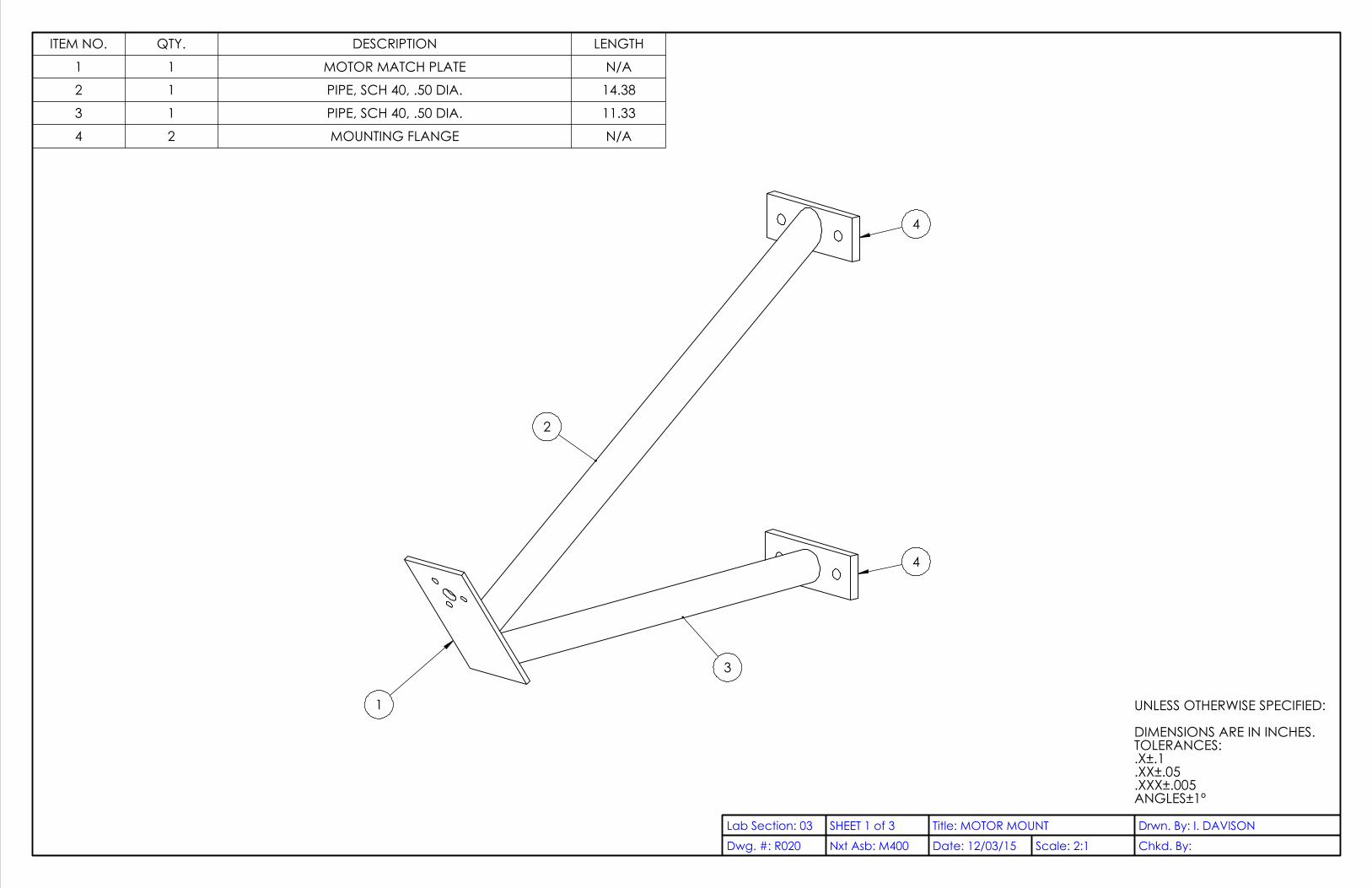
1
2
3
4
4
UNLESS OTHERWISE SPECIFIED:
DIMENSIONS ARE IN INCHES.TOLERANCES:.X±.1.XX±.05.XXX±.005ANGLES±1º
ITEM NO. QTY. DESCRIPTION LENGTH
1 1 MOTOR MATCH PLATE N/A
2 1 PIPE, SCH 40, .50 DIA. 14.38
3 1 PIPE, SCH 40, .50 DIA. 11.33
4 2 MOUNTING FLANGE N/A
Dwg. #: R020Lab Section: 03 SHEET 1 of 3
Nxt Asb: M400 Chkd. By:Date: 12/03/15Drwn. By: I. DAVISONTitle: MOTOR MOUNT
Scale: 2:1

.13
D
D
0 .50
1.00 2X 1.25
2.00
0
.57
1.43
2X 1.00
4.00
VIEW D-D
MOTOR MOUNT PLATE
Dwg. #: R020Lab Section: 03 SHEET 2 of 3
Nxt Asb: M400 Chkd. By:Date: 12/03/15Drwn. By: I. DAVISONTitle: MOTOR MOUNT
Scale: 1:1

14.38
55.00°
55.00°
11.33
0
2X
.57
1.1
4
0
.50
2.50
3.00
.25
QTY.: 2
Dwg. #: R020Lab Section: 03 SHEET 3 of 3
Nxt Asb: M400 Chkd. By:Date: 12/03/15Drwn. By: I. DAVISONTitle: MOTOR MOUNT
Scale: 1:2
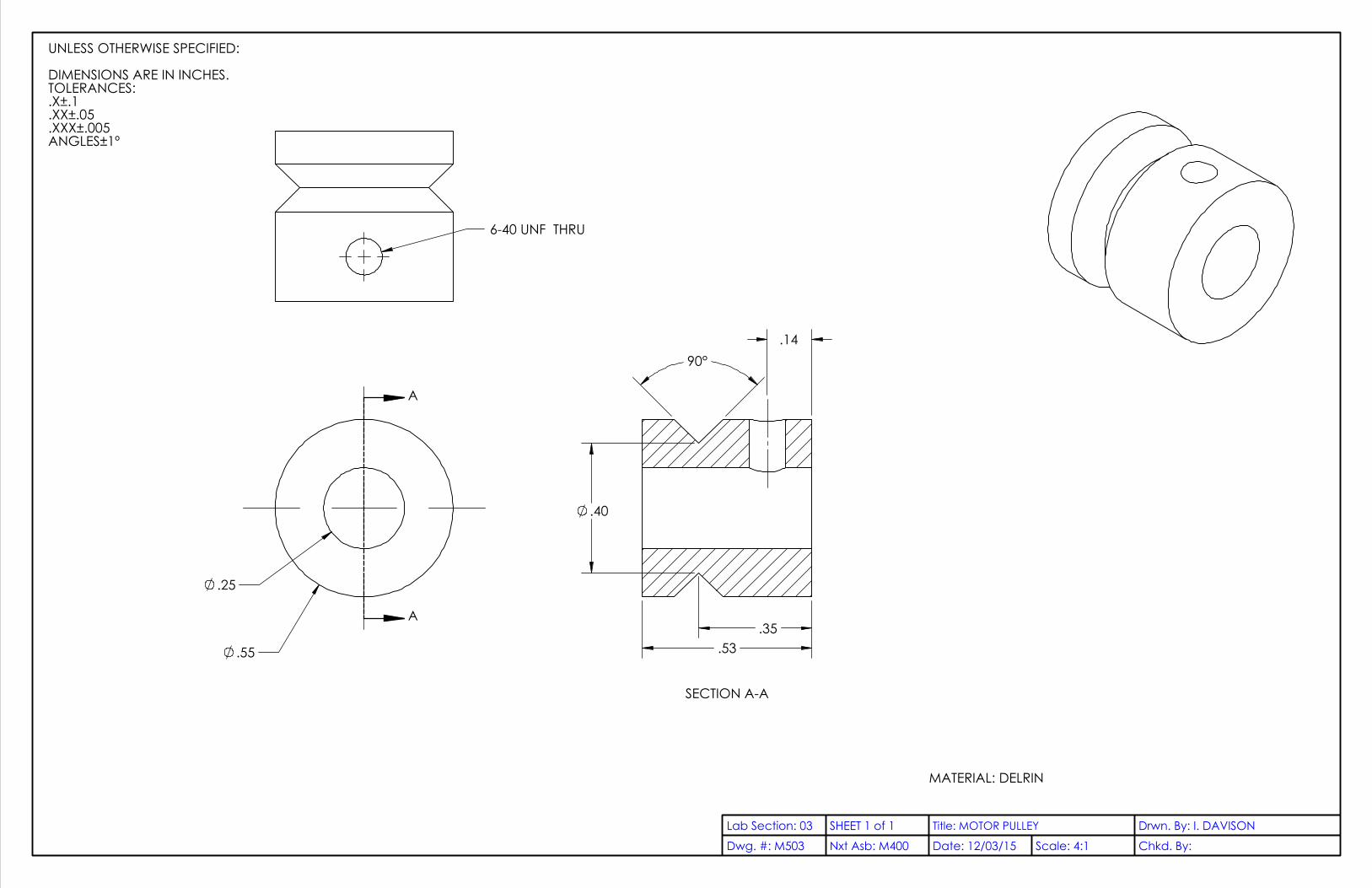
.55
.25
A
A
90°
.40
.53 .35
.14
SECTION A-A
6-40 UNF THRU
UNLESS OTHERWISE SPECIFIED:
DIMENSIONS ARE IN INCHES.TOLERANCES:.X±.1.XX±.05.XXX±.005ANGLES±1º
MATERIAL: DELRIN
Dwg. #: M503Lab Section: 03 SHEET 1 of 1
Nxt Asb: M400 Chkd. By: Date: 12/03/15Drwn. By: I. DAVISONTitle: MOTOR PULLEY
Scale: 4:1

UNLESS OTHERWISE SPECIFIED:
DIMENSIONS ARE IN INCHES.TOLERANCES:.X±.1.XX±.05.XXX±.005ANGLES±1º
Dwg. #: R700Lab Section: 03 SHEET 1 of 1
Nxt Asb: R000 Chkd. By:Date: 12/8/2015Drwn. By: I. DAVISONTitle: TRACKING CIRCUIT
Scale: 1:1

MATERIAL: STRINGLENGTH: 69.70 INCHES
UNLESS OTHERWISE SPECIFIED:
DIMENSIONS ARE IN INCHES.TOLERANCES:.X±.1.XX±.05.XXX±.005ANGLES±1º
Dwg. #: S001Lab Section: 03 SHEET 1 of 1
Nxt Asb: R000 Chkd. By:Date: 12/8/2015Drwn. By: I. DAVISONTitle: STRING
Scale: 1:4

Appendix K: Instructions

Device Installation Objective: To install the heliostat concentrator solar cooker to prepare it for cooking.
Materials: Heliostat concentrator solar cooker
Compass
String
Gravity-based angle finder
Procedure: 14. Assemble:
a. Rear Upright Assembly (R051)
b. Front Upright Assembly (R200)
c. Tracking Stage Assembly (R500)
15. First, find an area of ground 6 feet by 12 feet that is stable, flat, and that does not experience periods
of shade throughout the day.
16. Use the compass and mark a line about 5 feet long on the ground to establish a north-south axis.
a. Ensure that this line is true north-south, not magnetic north-south by correcting for
magnetic declination according to your latitude and longitude. This orientation is critical
for proper performance of the device.
b. Draw this line at the north end of the free area to ensure there is a free area at least an
additional 7 feet south of this line for the concentrator and kitchen setup.
17. At the south end of this line, use the compass to mark an east-west line that extends 2 feet in either
direction.
18. 49.5 inches north from the east-west line, dig a hole on the north-south line about 6 inches wide and
at least 20 inches deep.
19. Use this hole to secure the 4x4 post.
a. Ensure the post is perfectly vertical.
b. Ensure the sides of the post run north-south and east-west, and that the Top Bent Steel
Plate with Pipe Fitting (R011) is on the south-facing side of the 4x4.
c. One method to fill the hole: after placing the post, backfill with a small layer gravel, then
fill in the spaces with sand, and repeat until level with the ground.
20. Dig holes centered 1 foot east and west from the intersection of the marked lines at least 8” wide and
at least 20 inches deep.

21. Place R200 in the holes on the east-west line and install it vertically, ensuring the milled pivot bolt
(R012) faces the 4x4.
22. Ensure the two upright assemblies are positioned to incline the tracking stage at your latitude:
a. Connect a string to R012, then thread it through the hole in R011.
b. Measure the inclination of the string with the gravity-based angle finder.
c. Adjust the depth to which R200 will be buried until the inclination of the string matches
your latitude.
23. With at least two people, mount the tracking stage assembly:
a. Slide the bolt through the Top Bent Steel Plate,
b. Place the bottom on the Pivot Bolt of the front upright assembly, and
c. Secure the top with the 3/”-16 Locknut.
24. Attach the motor mount to the 4x4 as shown in R000.
25. Attach the string and spring to the motor mount, pulley, and .25” peg on the tracking stage
assembly’s cross pipe.
26. Secure the tracking circuit to the underside of the upper instance of M004 on the tracking stage
assembly.
27. As soon as the device is plugged in to the battery it is ready for use.

Instructions for Use: Let’s Cook Something! Objective: To cook food with the power of the sun.
Materials: Heliostat-Concentrator Solar Cooker
Cookstand
Cookware
Sunglasses
Food
Sunlight
Procedure: 1. Rotate the device so the mirrors face east (if you are in the northern hemisphere).
2. Power the tracking circuit (if your device is set up with a solar panel disregard step 1) and step back
to allow the device to orient itself properly.
3. Ensure you are wearing eye protection (e.g. sunglasses) and oven mitts as you approach the hotspot.
4. Place your food filled pot or pan in the hotspot on the cooking stand.
5. Whenever you approach the device to stir your food or check its status, ensure you are wearing proper
protection.