Final Focus Test Facility at ATF -...
30
ATF2 Overview Final Focus Test Facility at ATF presented by T. Tauchi, ILC-Asia WG4: Beam Delivery at ATF2 mini-workshop, SLAC 5 January, 2005
Transcript of Final Focus Test Facility at ATF -...
ATF2 OverviewFinal Focus Test Facility at ATF
presented by T. Tauchi,ILC-Asia WG4: Beam Delivery
at ATF2 mini-workshop, SLAC
5 January, 2005
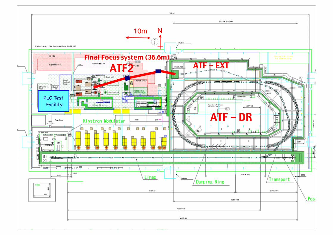
Final Focus system (36.6m)
10m N
PLC Test Facility
ATF – DR
ATF – EXTATF2
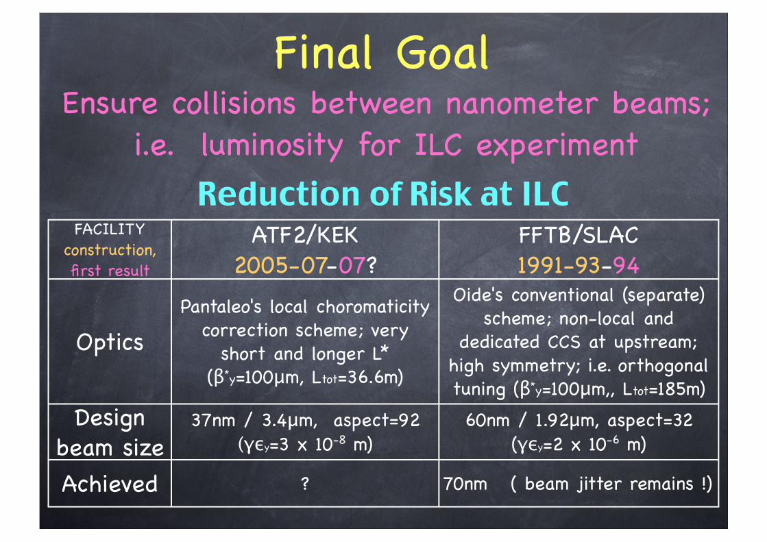
Final GoalEnsure collisions between nanometer beams;
i.e. luminosity for ILC experiment
FACILITYconstruction, first result
ATF2/KEK2005-07-07?
FFTB/SLAC1991-93-94
OpticsPantaleo's local choromaticity
correction scheme; very short and longer L*
(β*y=100μm, Ltot=36.6m)
Oide's conventional (separate) scheme; non-local and
dedicated CCS at upstream; high symmetry; i.e. orthogonal tuning (β*y=100μm,, Ltot=185m)
Design beam size
37nm / 3.4μm, aspect=92(γεy=3 x 10⁻⁸ m)
60nm / 1.92μm, aspect=32(γεy=2 x 10⁻⁶ m)
Achieved ? 70nm ( beam jitter remains !)
Reduction of Risk at ILC
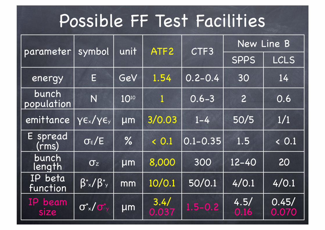
parameter symbol unit ATF2 CTF3New Line B
SPPS LCLS
energy E GeV 1.54 0.2-0.4 30 14bunch
population N 1010 1 0.6-3 2 0.6
emittance γεx/γεy μm 3/0.03 1-4 50/5 1/1
E spread (rms) σE/E % < 0.1 0.1-0.35 1.5 < 0.1
bunch length σZ μm 8,000 300 12-40 20IP beta function β*x/β*y mm 10/0.1 50/0.1 4/0.1 4/0.1
IP beam size σ*x/σ*y μm 3.4/
0.037 1.5-0.2 4.5/0.16
0.45/0.070
Possible FF Test Facilities
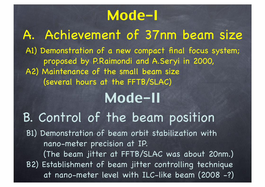
Mode-I A. Achievement of 37nm beam size A1) Demonstration of a new compact final focus system; proposed by P.Raimondi and A.Seryi in 2000, A2) Maintenance of the small beam size (several hours at the FFTB/SLAC)
Mode-II B. Control of the beam position B1) Demonstration of beam orbit stabilization with nano-meter precision at IP. (The beam jitter at FFTB/SLAC was about 20nm.) B2) Establishment of beam jitter controlling technique at nano-meter level with ILC-like beam (2008 -?)
ATF2 OperationThe mode-I and -II can not go together for BSM and IP-BPM at the same FP.
First, ATF2 will operate in the mode-I with the BSM.
Next, ATF2 will operate in the mode-II with the IP-BPM.
In long term, ATF2 will interchangeably operate the mode-I and -II.
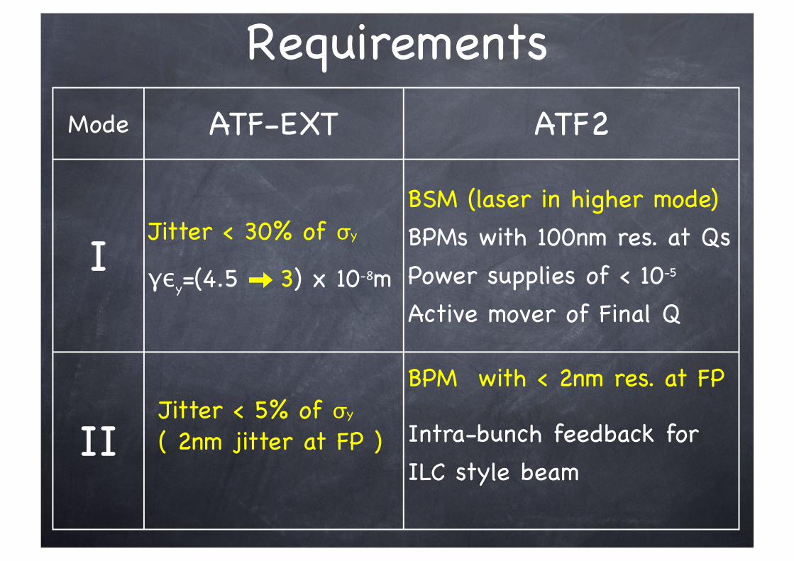
RequirementsMode ATF-EXT ATF2
IJitter < 30% of σy
γεy=(4.5 3) x 10-8m
BSM (laser in higher mode)BPMs with 100nm res. at QsPower supplies of < 10-5
Active mover of Final Q
II Jitter < 5% of σy
( 2nm jitter at FP )
BPM with < 2nm res. at FP
Intra-bunch feedback forILC style beam

Mode-I
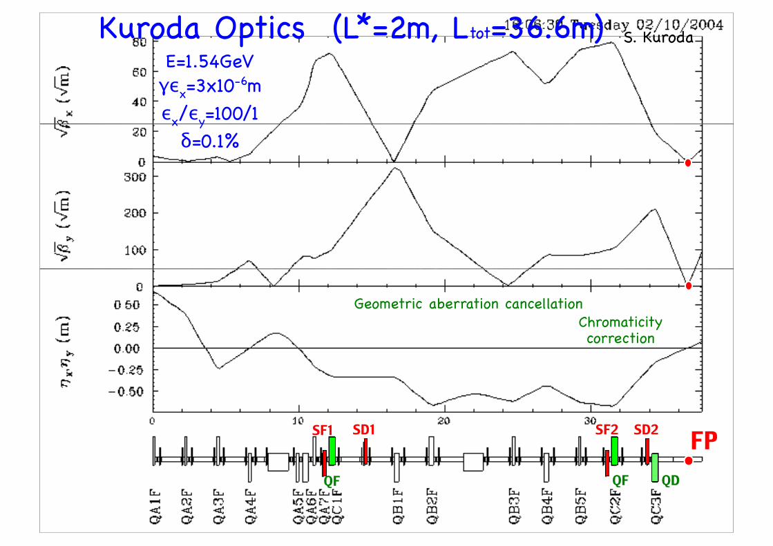
SF1 SD1 SF2 SD2
QF QDQF
S. KurodaKuroda Optics (L*=2m, Ltot=36.6m)
FP
E=1.54GeVγεx=3x10
-6mεx/εy=100/1δ=0.1%
Geometric aberration cancellationChromaticity correction
0.8
1
1.2
1.4
1.6
1.8
2
2.2
0 0.2 0.4 0.6 0.8 1 1.2 1.4 1.6
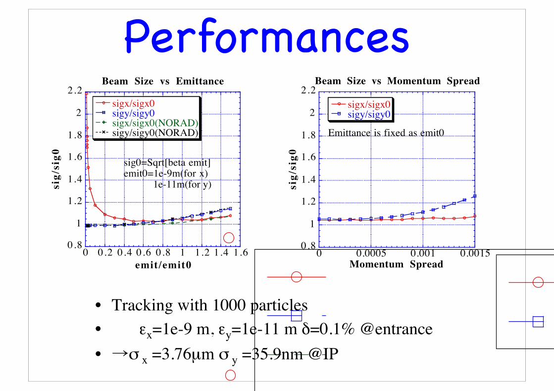
Beam Size vs Emittance
sigx/sigx0sigy/sigy0sigx/sigx0(NORAD)sigy/sigy0(NORAD)
sig/
sig0
emit/emit0
sig0=Sqrt[beta emit]emit0=1e-9m(for x) 1e-11m(for y)
0.8
1
1.2
1.4
1.6
1.8
2
2.2
0 0.0005 0.001 0.0015
Beam Size vs Momentum Spread
sigx/sigx0sigy/sigy0
sig/
sig0
Momentum Spread
Emittance is fixed as emit0
• Tracking with 1000 particles• εx=1e-9 m, εy=1e-11 m δ=0.1% @entrance• →σ x =3.76µm σ y =35.9nm @IP
Performances
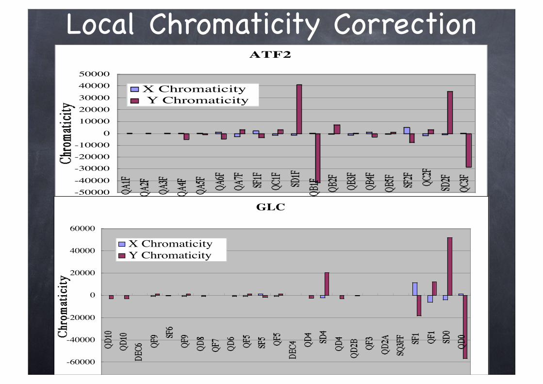
ATF2
-50000-40000-30000-20000-10000
01000020000300004000050000
Element
X Chromaticity Y Chromaticity
GLC
-80000
-60000
-40000
-20000
0
20000
40000
60000
Element
X Chromaticity Y Chromaticity
Local Chromaticity Correction
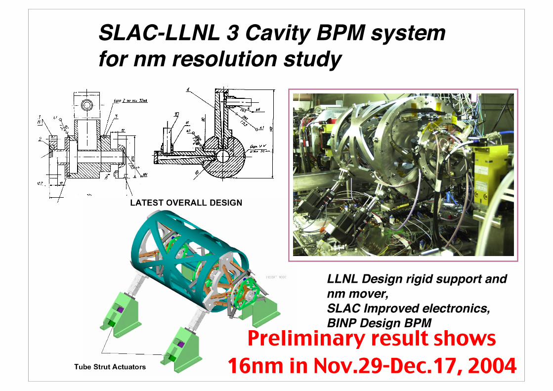
SLAC-LLNL 3 Cavity BPM systemfor nm resolution study
LLNL Design rigid support andnm mover,SLAC Improved electronics,BINP Design BPM
Achieved resolution 50nmPreliminary result shows 16nm in Nov.29-Dec.17, 2004
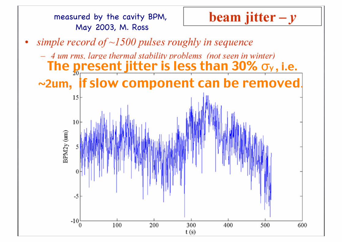
measured by the cavity BPM, May 2003, M. Ross
The present jitter is less than 30% σy , i.e. ~2um, if slow component can be removed.

Mode-II
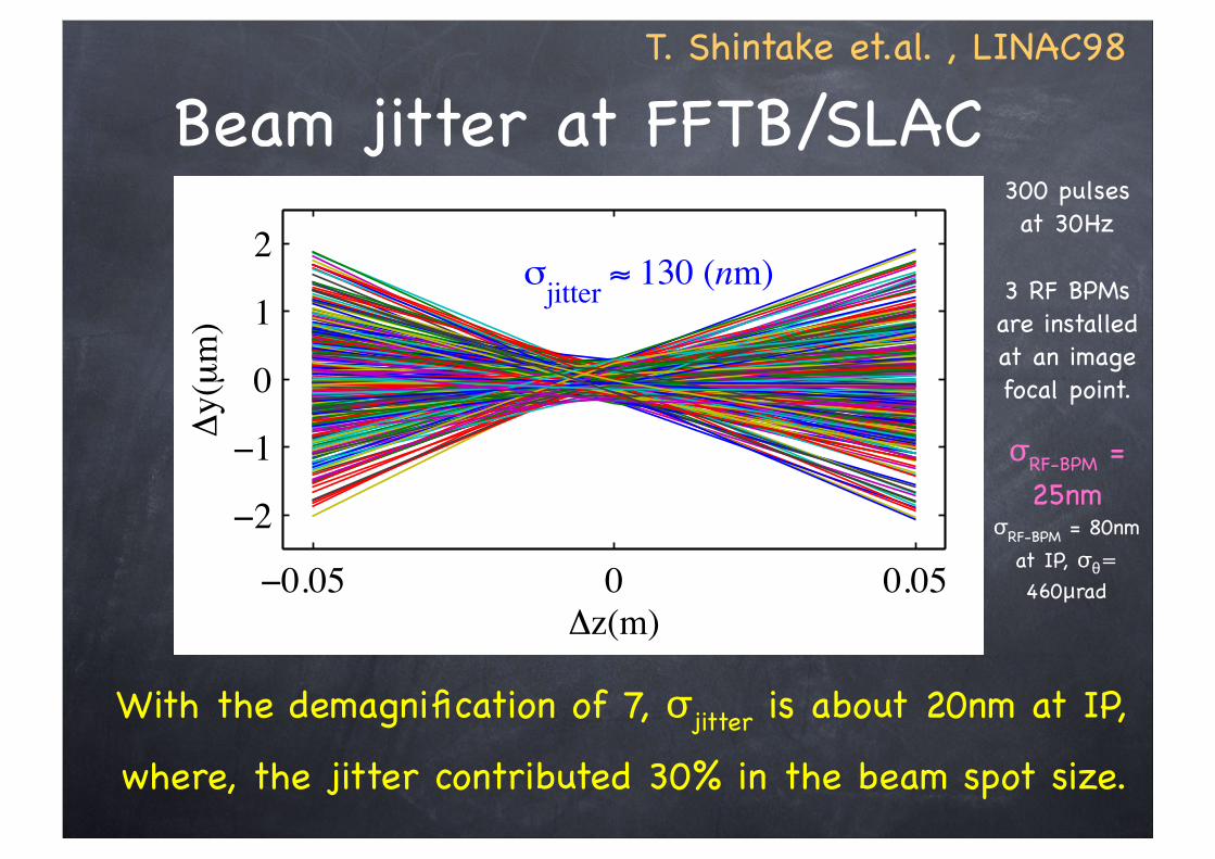
Beam jitter at FFTB/SLACT. Shintake et.al. , LINAC98
!"!!=#
140 nm at these BPMs. This set of BPMs is used for the
resolution measurement, as well as for characterizing the
beam’s jitter parameters before entering the final
transformer.
2 EXPERIMENT CONFIGURATION
The RF-BPMs are a typical pill box cavity design
producing a signal containing four components
(1)
where q is the beam charge, y is the beam’s offset with
respect to the center of the cavity, y’ is the beam’s angle
with respect to the cavity (y’=dy/dz), y0 is an offset
which comes from the TM010
signal (common mode), and
j denotes the imaginary terms.
The signals from the RF-BPM are sent through a 180o
hybrid that significantly reduces the second and third
term in equation 1. The difference signal from the
hybrid is passed into a RF receiver circuit. The RF
receiver circuit is set up as a heterodyne synchronous
detector that extracts the amplitude and polarity of the
BPM signal. The beam induced waveform is filtered at
5712 MHz and mixed down to 500 MHz. The 500 MHz
signal is then filtered, amplified, and mixed down to 50
MHz. This signal is again filtered and amplified and
passed to a dual track and hold (NiTNH) module, a 16
bit digitizer with a ±2 volt limit and a 300 MHz
bandwidth. The digital signal is converted into beam
position and read by the SLC Control Program (SCP).
The measured dynamic range of the receiver is 51
dBm with measured noise of -82 dBm or 1 nm for a
beam charge of 1 nC. The gain factor for the system is
measured by moving the BPMs with respect to the beam
(see section 3 below for this process).
3 DATA ACQUISITION
Before being used for data acquisition, the RF-BPMs
were phased to the electron beam and a signal to
position calibration constant was measured. Phasing was
accomplished by using a fourth cavity which is located
at the end of the triplet stack (see figure 1). Since the
BPMs were phased to the beam, drifting due to timing
signals were eliminated. The calibration constant was
measured by moving the BPMs with respect to the beam.
Calibrated linear variable differential transformers
(LVDTs) measured the change in the BPM’s position
while the change in the BPM’s signal is recorded. Within
the dynamic range of the receiver, position verses signal
is linear and the slope is the gain or calibration constant.
This calibration constant is stored in the SCP’s database
for use with the BPM acquisition software. The
maximum beam rate of the FFTB is 30 Hz. The signals
from RF-BPMs are acquired simultaneously with the
signals from standard BPMs up to the acquisition rate of
30 Hz. This allows for the comparison of the beam
positions measured by the RF-BPMs to that measured by
the standard BPMs.
4 DATA ANALYSIS
The top plot in figure 2 displays beam trajectories for
approximately 300 machine pulses at an acquisition rate
of 30 Hz. The beam’s waist at the IMFP is close to the
middle RF-BPM of the triplet set. With only drift spaces
between the BPMs, the calculation of the slope and
offset for each beam trajectory at the center BPM does
not require knowledge of beam line optics. The bottom
plot in figure 2 shows angles verses positions with a one
sigma ellipse. This is a measurement of the jitter
emittance which is equal to 1.533 µm. The equation for
the emittance is
(2)
where y is the measured position at the center BPM, y’ is
the measured angle using all three BPMs (y’=dy/dz), and
<…> means an average over a series of measurements
with a fixed time limit. The jitter emittance is close to
one tenth of the beam emittance, which is expected for
the observed beam jitter to beam size fraction of 30% in
the SLC. This is an important measurement because it
shows that the RF-BPMs agree with standard BPMs.
+++=
!0.05 0 0.05
!2
!1
0
1
2$
y(µ
m)
$z(m)
%jitter
& 130 (nm)
!0.3 !0.2 !0.1 0 0.1 0.2 0.3
!40
!20
0
20
40
yp
(µra
d)
y(µm)
#jitter
& 1.533 (um)
Figure 2. The top plot displays the measured beamtrajectories. The bottom plot shows the calculatedjitter emittance.
912
With the demagnification of 7, σjitter is about 20nm at IP,
where, the jitter contributed 30% in the beam spot size.
300 pulses at 30Hz
3 RF BPMs are installed at an image focal point.
σRF-BPM = 25nm
σRF-BPM = 80nm at IP, σθ=460μrad
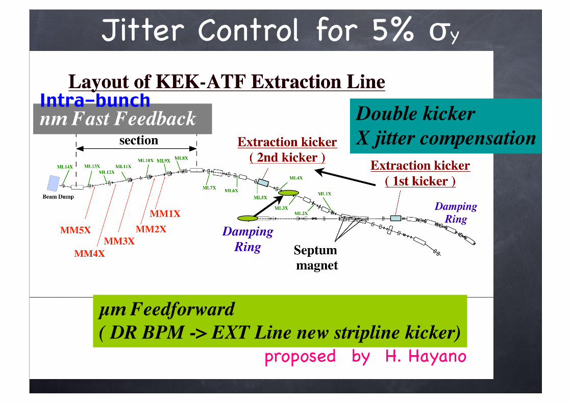
Jitter Control for 5% σy
nm Fast Feedback Double kicker X jitter compensation
µm Feedforward( DR BPM -> EXT Line new stripline kicker)
proposed by H. Hayano
Intra-bunch
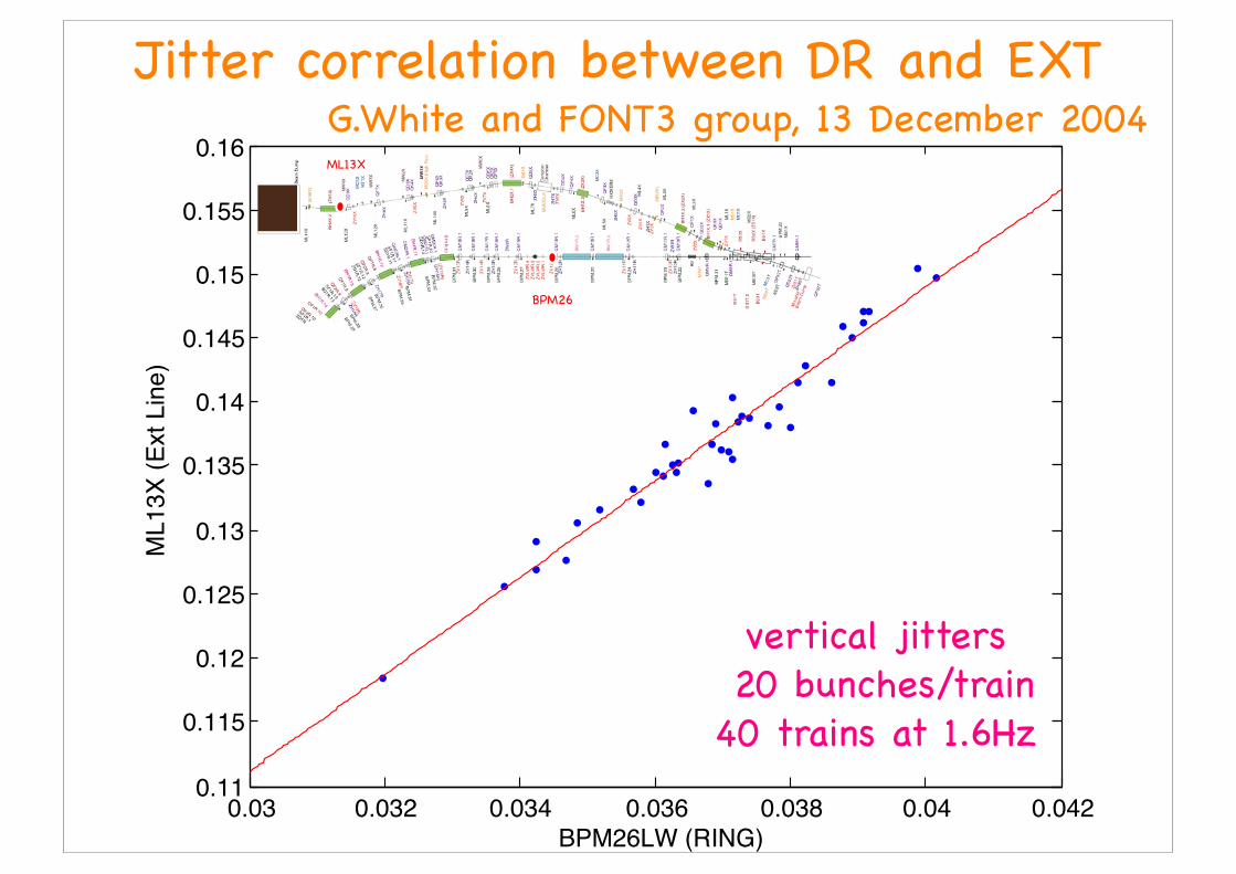
ML13X
BPM26
0.03 0.032 0.034 0.036 0.038 0.04 0.0420.11
0.115
0.12
0.125
0.13
0.135
0.14
0.145
0.15
0.155
0.16
BPM26LW (RING)
ML13X
(E
xt Lin
e)
G.White and FONT3 group, 13 December 2004Jitter correlation between DR and EXT
vertical jitters 20 bunches/train40 trains at 1.6Hz
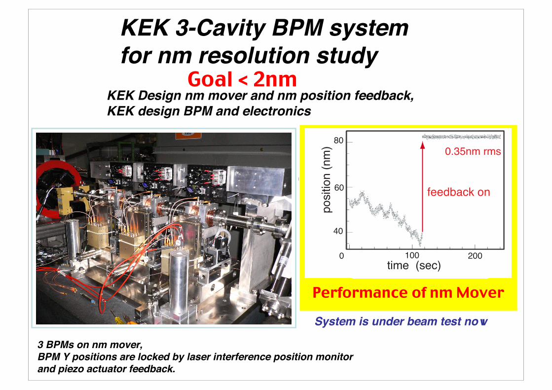
KEK 3-Cavity BPM system for nm resolution study
KEK Design nm mover and nm position feedback,KEK design BPM and electronics
6.5GHz cavity BPM.Sensor cavity and reference cavity are in one body.Symmetric signal extraction.
3 BPMs on nm mover,BPM Y positions are locked by laser interference position monitor and piezo actuator feedback.
System is under beam test now
Goal < 2nm
0
0.35nm rms
feedback on
200100
time (sec)0
80
60
40
positio
n (
nm
)
Performance of nm Mover
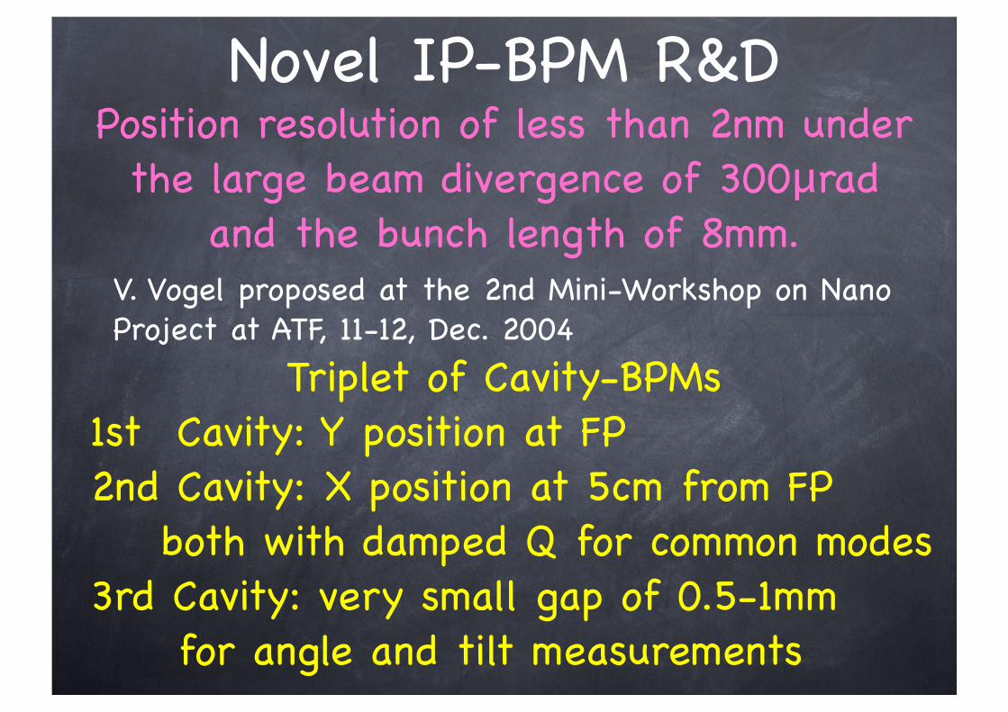
Novel IP-BPM R&DPosition resolution of less than 2nm under the large beam divergence of 300μrad
and the bunch length of 8mm.V. Vogel proposed at the 2nd Mini-Workshop on Nano Project at ATF, 11-12, Dec. 2004
Triplet of Cavity-BPMs 1st Cavity: Y position at FP 2nd Cavity: X position at 5cm from FP both with damped Q for common modes 3rd Cavity: very small gap of 0.5-1mm for angle and tilt measurements
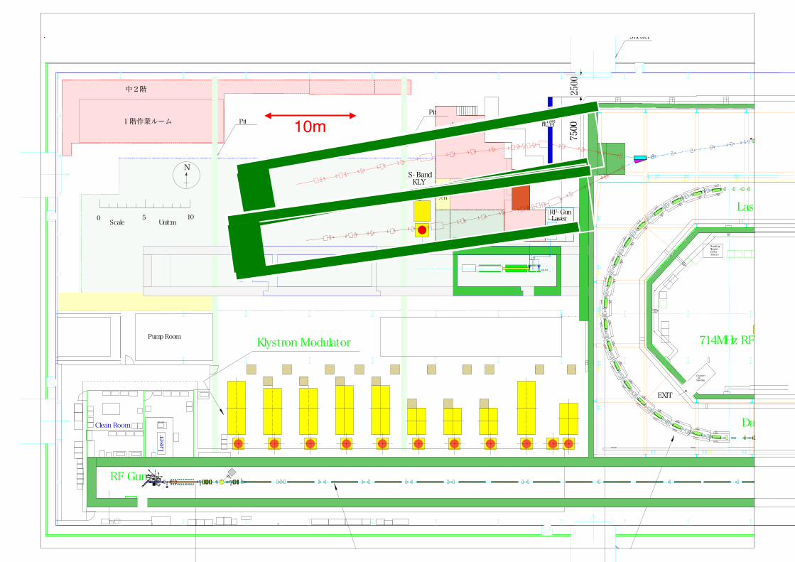
中2階
1階作業ルーム 中2階
1階作業エリア1階部分共有
7500
2500
配管
1階部分のみ X- bandで使用
RF Gun
Pump Room
Shutter
PitPit
BendingMagnetPowerSource
Clean Room
Klystron Modulator
Laser
S-band Linac
Damped
714MHz RF sour
Laser Wi
Clearance forShielding
EXIT
road lock
S- Band KLY
RF-Gun Laser0 5 10
Scale Unit:m
N
10m
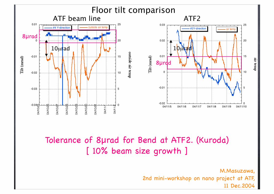
Floor tilt comparison
10µrad10µrad
ATF beam line ATF2
4µrad
14 degree!KEKB tunnel floor
temp
tilt
ATF floor tilt, similar to KEKB tunnel floor
KEKB tunnel tilt measurementsKEK preprint 03-97
M.Masuzawa, 2nd mini-workshop on nano project at ATF,
11 Dec.2004
Tolerance of 8μrad for Bend at ATF2. (Kuroda)[ 10% beam size growth ]
8μrad
8μrad
Comparison between ATF (Jpower meas. Feb.) & ATF2 (Dec.)
Red : ATF2Blue : ATFDiffference in vertical direction is largest.!agrees with Yamaoka’s measurememt.
Fair comparison??“Noiser” around ATF2 (chiller pumpsnear by, other activities going on, etc.)Taken on different days.
Day-to-day fluctuations in ATF2 area? !
X Y
V
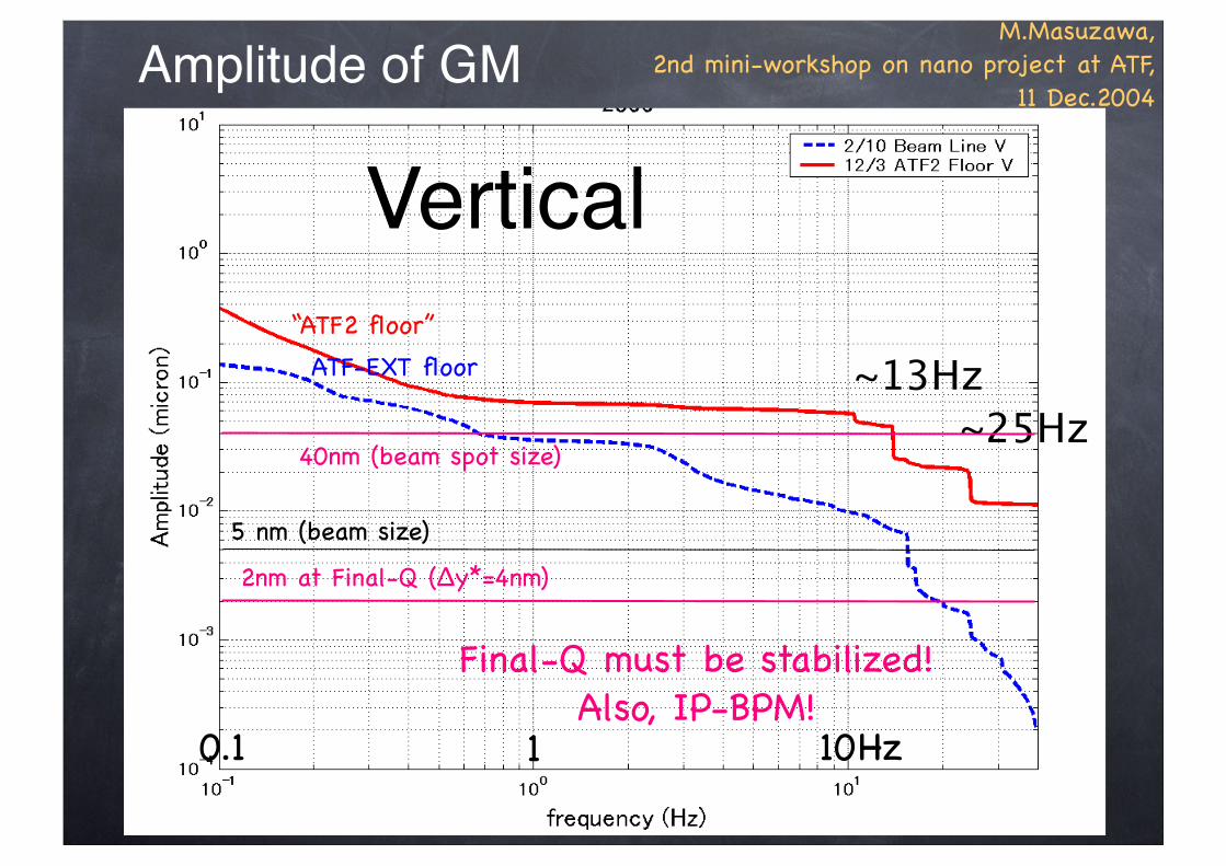
~13Hz
~25Hz
M.Masuzawa, 2nd mini-workshop on nano project at ATF,
11 Dec.2004
Vertical
40nm (beam spot size)
2nm at Final-Q (Δy*=4nm)
5 nm (beam size)
0.1 1 10Hz
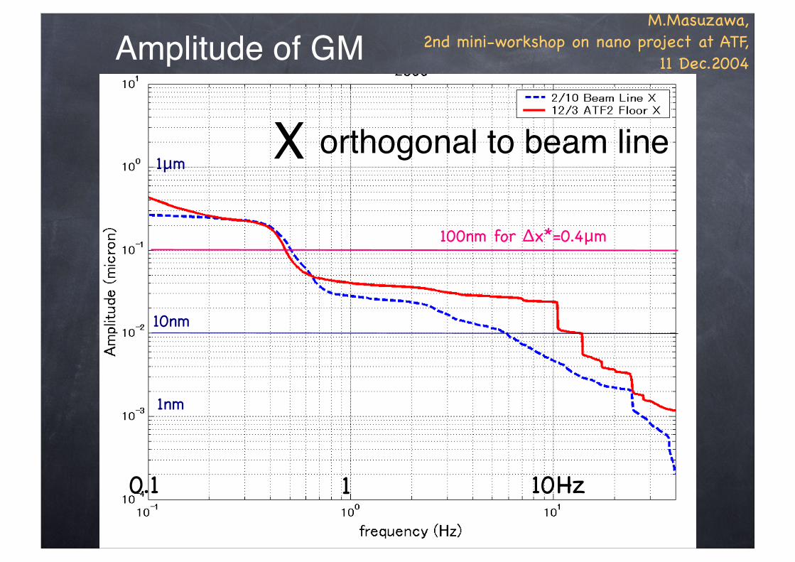
Amplitude of GM
Final-Q must be stabilized!Also, IP-BPM!
“ATF2 floor”
ATF-EXT floor
Comparison between ATF (Jpower meas. Feb.) & ATF2 (Dec.)
Red : ATF2Blue : ATFDiffference in vertical direction is largest.!agrees with Yamaoka’s measurememt.
Fair comparison??“Noiser” around ATF2 (chiller pumpsnear by, other activities going on, etc.)Taken on different days.
Day-to-day fluctuations in ATF2 area? !
X Y
V
~13Hz
~25Hz
M.Masuzawa, 2nd mini-workshop on nano project at ATF,
11 Dec.2004
orthogonal to beam line
100nm for Δx*=0.4μm
10nm
0.1 1 10Hz
Amplitude of GM
1nm
1μm
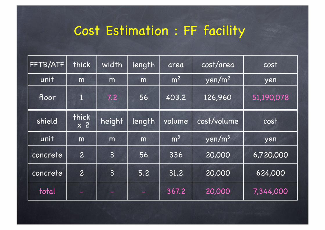
FFTB/ATF thick width length area cost/area cost
unit m m m m2 yen/m2 yen
floor 1 7.2 56 403.2 126,960 51,190,078
shield thick x 2 height length volume cost/volume cost
unit m m m m3 yen/m3 yen
concrete 2 3 56 336 20,000 6,720,000
concrete 2 3 5.2 31.2 20,000 624,000
total - - - 367.2 20,000 7,344,000
Cost Estimation : FF facility
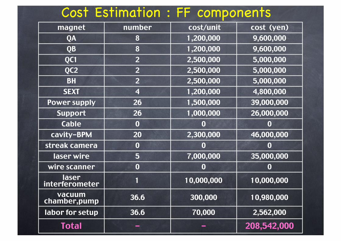
magnet number cost/unit cost (yen)QA 8 1,200,000 9,600,000QB 8 1,200,000 9,600,000
QC1 2 2,500,000 5,000,000QC2 2 2,500,000 5,000,000BH 2 2,500,000 5,000,000
SEXT 4 1,200,000 4,800,000Power supply 26 1,500,000 39,000,000
Support 26 1,000,000 26,000,000Cable 0 0 0
cavity-BPM 20 2,300,000 46,000,000streak camera 0 0 0
laser wire 5 7,000,000 35,000,000wire scanner 0 0 0
laser interferometer 1 10,000,000 10,000,000
vacuum chamber,pump 36.6 300,000 10,980,000
labor for setup 36.6 70,000 2,562,000
Total - - 208,542,000
Cost Estimation : FF components
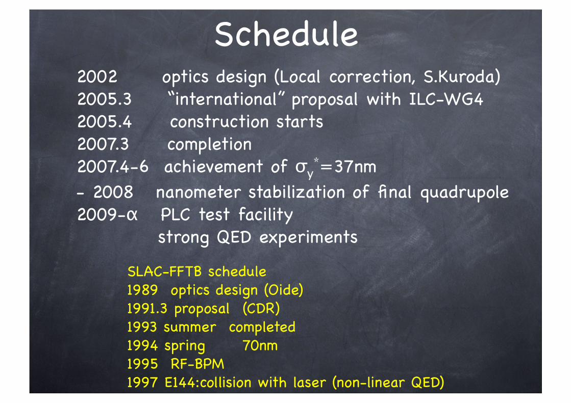
Schedule2002 optics design (Local correction, S.Kuroda)2005.3 “international” proposal with ILC-WG42005.4 construction starts2007.3 completion2007.4-6 achievement of σy*=37nm- 2008 nanometer stabilization of final quadrupole2009-α PLC test facility strong QED experiments
SLAC-FFTB schedule1989 optics design (Oide)1991.3 proposal (CDR)1993 summer completed1994 spring 70nm1995 RF-BPM1997 E144:collision with laser (non-linear QED)
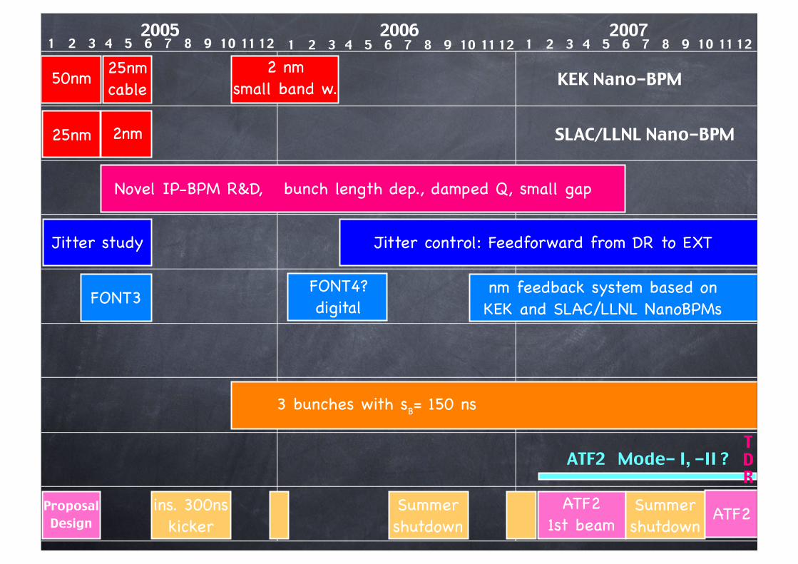
KEK Nano-BPM
ProposalDesign
ATF21st beam
2005 1 2 3 4 5 6 7 8 9 10 11 12
2006 1 2 3 4 5 6 7 8 9 10 11 12
2007 1 2 3 4 5 6 7 8 9 10 11 12
Summershutdown
Summershutdown
ins. 300ns kicker
50nm 25nmcable
2 nmsmall band w.
FONT3
SLAC/LLNL Nano-BPM
FONT4?digital
3 bunches with sB= 150 ns
Jitter control: Feedforward from DR to EXT
nm feedback system based on KEK and SLAC/LLNL NanoBPMs
25nm
Novel IP-BPM R&D, bunch length dep., damped Q, small gap
Jitter study
ATF2
ATF2 Mode- I, -II ?TDR
2nm
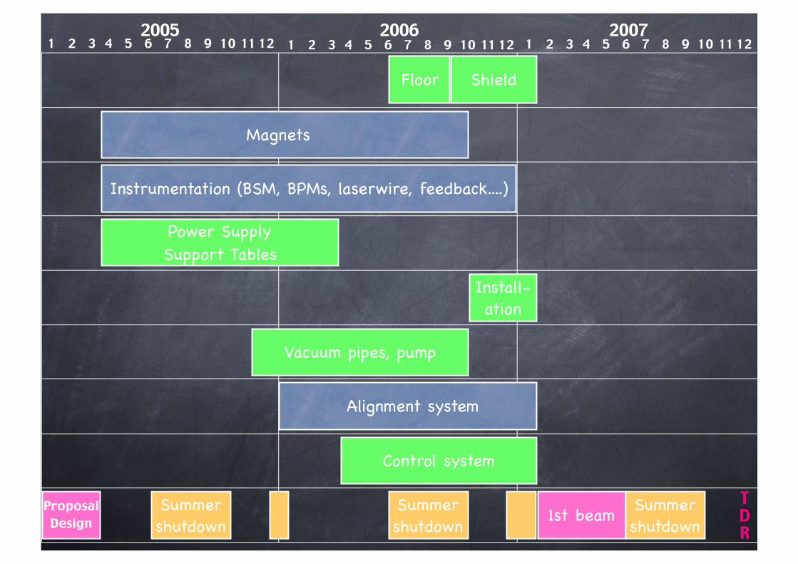
Power SupplySupport Tables
Floor
Magnets
Instrumentation (BSM, BPMs, laserwire, feedback....)
Install-ation
Vacuum pipes, pump
Alignment system
Control system
ProposalDesign 1st beam
2005 1 2 3 4 5 6 7 8 9 10 11 12
2006 1 2 3 4 5 6 7 8 9 10 11 12
2007 1 2 3 4 5 6 7 8 9 10 11 12
Summershutdown
Summershutdown
Summershutdown
TDR
Shield
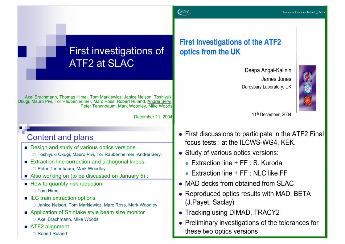
First investigations of
ATF2 at SLAC
Axel Brachmann, Thomas Himel, Tom Markiewicz, Janice Nelson, ToshiyukiOkugi, Mauro Pivi, Tor Raubenheimer, Marc Ross, Robert Ruland, Andrei Seryi,
Peter Tenenbaum, Mark Woodley, Mike Woods
December 11, 2004
2
Content and plans! Design and study of various optics versions
" Toshiyuki Okugi, Mauro Pivi, Tor Raubenheimer, Andrei Seryi
! Extraction line correction and orthogonal knobs
" Peter Tenenbaum, Mark Woodley
! Also working on (to be discussed on January 5) :
! How to quantify risk reduction
" Tom Himel
! ILC train extraction options
" Janice Nelson, Tom Markiewicz, Marc Ross, Mark Woodley
! Application of Shintake style beam size monitor
" Axel Brachmann, Mike Woods
! ATF2 alignment
" Robert Ruland
First Investigations of the ATF2
optics from the UK
Deepa Angal-Kalinin
James Jones
Daresbury Laboratory, UK
11th December, 2004
2
! First discussions to participate in the ATF2 Final
focus tests : at the ILCWS-WG4, KEK.
! Study of various optics versions:
! Extraction line + FF : S. Kuroda
! Extraction line + FF : NLC like FF
! MAD decks from obtained from SLAC
! Reproduced optics results with MAD, BETA
(J.Payet, Saclay)
! Tracking using DIMAD, TRACY2
! Preliminary investigations of the tolerances for
these two optics versions

Author List is Open.So, please
Join us !
Contributed paper to PAC05, Knoxville, Tennessee, 16-20 May,2005
PROPOSAL OF THE NEXT INCARNATION OF ACCELERATOR TEST
FACILITY AT KEK FOR THE INTERNATIONAL LINEAR COLLIDER
H.Hayano, Y.Higashi, Y.Honda, Y.Iwashita, M.Kuriki, S.Kuroda, K.Kubo, M.Kumada,
M.Masuzawa, T.Mihara, T.Okugi, T.Sanuki, R.Sugahara, T.Takahashi, T.Tauchi, J.Urakawa V.Vogel,
H.Yamaoka, K.Yokoya Univ.Tokyo/Kyoto/NIRS/KEK, Japan
I.Agapov, D.Angal-Kalinin, R.Appleby, G.A.Blair, S.Boogert, P.N.Burrows, J.Carter, G.Christian,
N. Delerue, C.Driouichi, J.Jones, A.Kalinin, S.Malton, S.Molloy, A.Reichold, D.Urner, G.White,
CCLRC/Oxford/ QMUL/RHUL/UCL, UK
P.Bambade, O.Napoly, J.Payet, Saclay/Orsay, France
H.Brauu, D.Schulte, F.Zimmermann, CERN, Switzerland
N.Names, DESY, Germany
B.Grishanov, F.Podgorny, V.Telnov, BINP, Russia
A.Brachmann, J.Gronberg, T.Himel, T.Markiewicz, J.Nelson, M.Pivi, T.Raubenheimer, M.Ross,
A.Seryi, C.Spencer, P.Tenenbaum, E.Torrence, M.Woodley, M.Woods, Univ.Oregon/LLNL/SLAC,
USA
Abstract
The realization of the International Linear Collider (ILC) will require the ability to create and reliably maintain
nanometer size beams. The ATF damping ring is the unique facility where ILC emittancies are possible. In this paper we
present and evaluate the proposal to create a final focus facility at the ATF which, using compact final focus optics and
an ILC-like bunch train, would be capable of achieving 35nm beam size. Such a facility would enable the development
of beam diagnostics and tuning methods, as well as the training of young accelerator physicists.