
Figure 18-1 Fiber-optic communication system.
34
Modern Electronic Communication 9th edition Jeffrey S. Beasley and Gary M. Miller Copyright ©2008 by Pearson Education, Inc. Upper Saddle River, New Jersey 07458 All rights reserved. Figure 18-1 Fiber-optic communication system.
-
Upload
zahir-ellis -
Category
Documents
-
view
56 -
download
3
description
Figure 18-1 Fiber-optic communication system. Figure 18-2 Refraction of light. Figure 18-3 Critical angle. Figure 18-4 The electromagnetic wavelength spectrum. Figure 18-5 Single-fiber construction. Figure 18-6 (a) Development of numerical aperture; (b) acceptance cone. - PowerPoint PPT Presentation
Transcript of Figure 18-1 Fiber-optic communication system.

Modern Electronic Communication 9th editionJeffrey S. Beasley and Gary M. Miller
Copyright ©2008 by Pearson Education, Inc.Upper Saddle River, New Jersey 07458
All rights reserved.
Figure 18-1 Fiber-optic communication system.

Modern Electronic Communication 9th editionJeffrey S. Beasley and Gary M. Miller
Copyright ©2008 by Pearson Education, Inc.Upper Saddle River, New Jersey 07458
All rights reserved.
Figure 18-2 Refraction of light.
Modern Electronic Communication 9th editionJeffrey S. Beasley and Gary M. Miller
Copyright ©2008 by Pearson Education, Inc.Upper Saddle River, New Jersey 07458
All rights reserved.
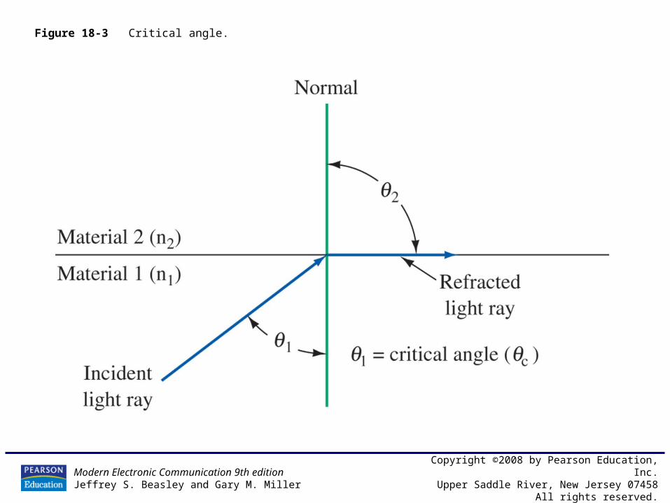
Figure 18-3 Critical angle.

Modern Electronic Communication 9th editionJeffrey S. Beasley and Gary M. Miller
Copyright ©2008 by Pearson Education, Inc.Upper Saddle River, New Jersey 07458
All rights reserved.
Figure 18-4 The electromagnetic wavelength spectrum.
Modern Electronic Communication 9th editionJeffrey S. Beasley and Gary M. Miller
Copyright ©2008 by Pearson Education, Inc.Upper Saddle River, New Jersey 07458
All rights reserved.
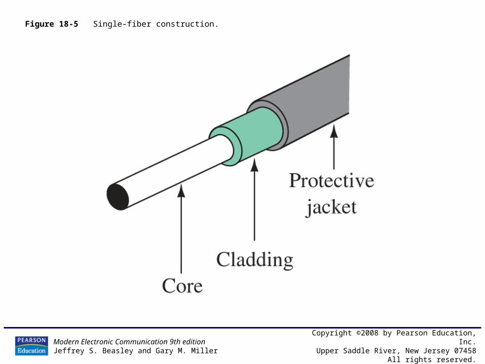
Figure 18-5 Single-fiber construction.
Modern Electronic Communication 9th editionJeffrey S. Beasley and Gary M. Miller
Copyright ©2008 by Pearson Education, Inc.Upper Saddle River, New Jersey 07458
All rights reserved.
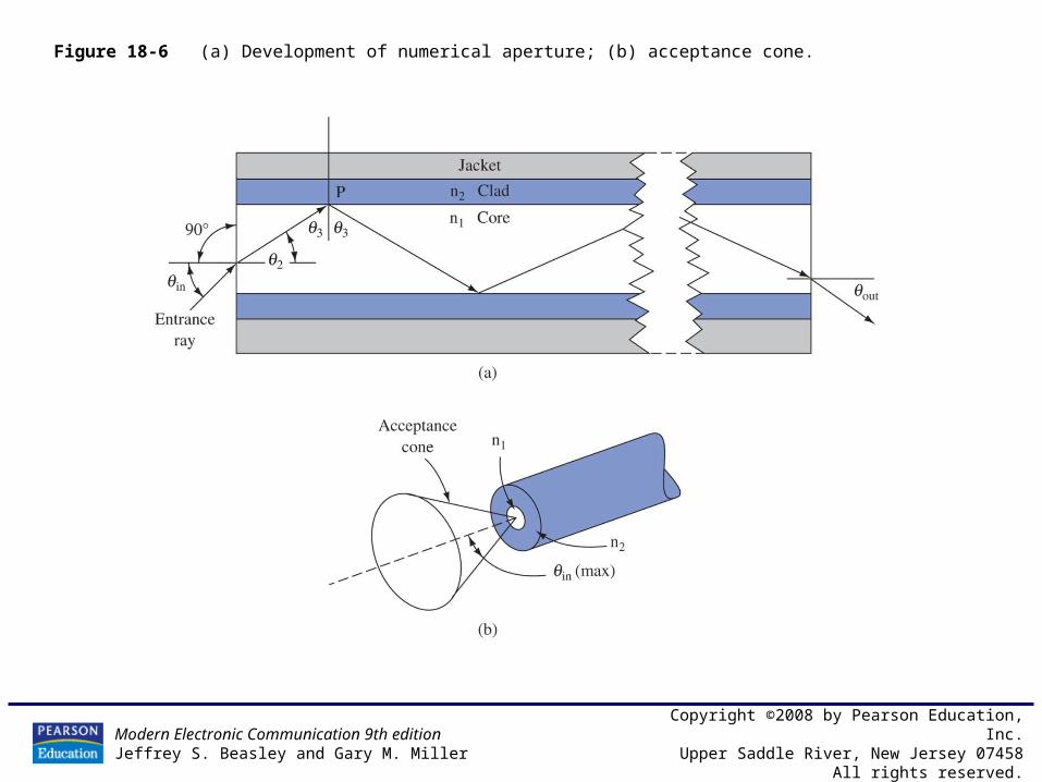
Figure 18-6 (a) Development of numerical aperture; (b) acceptance cone.

Modern Electronic Communication 9th editionJeffrey S. Beasley and Gary M. Miller
Copyright ©2008 by Pearson Education, Inc.Upper Saddle River, New Jersey 07458
All rights reserved.
Figure 18-7 Modes of propagation for step-index fiber.
Modern Electronic Communication 9th editionJeffrey S. Beasley and Gary M. Miller
Copyright ©2008 by Pearson Education, Inc.Upper Saddle River, New Jersey 07458
All rights reserved.
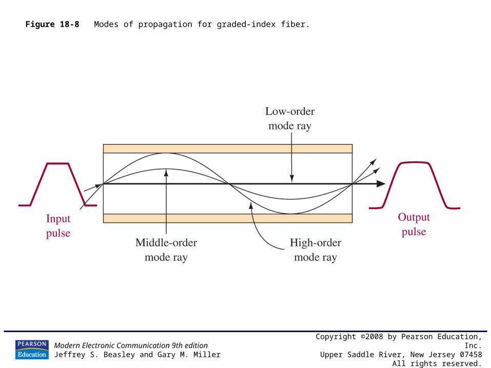
Figure 18-8 Modes of propagation for graded-index fiber.
Modern Electronic Communication 9th editionJeffrey S. Beasley and Gary M. Miller
Copyright ©2008 by Pearson Education, Inc.Upper Saddle River, New Jersey 07458
All rights reserved.
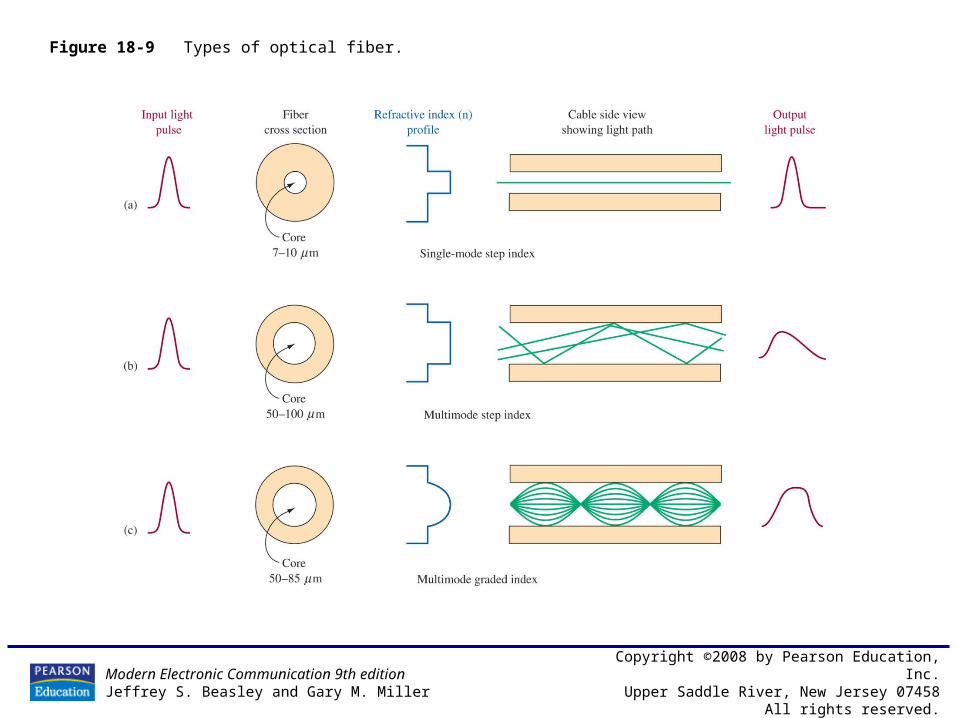
Figure 18-9 Types of optical fiber.
Modern Electronic Communication 9th editionJeffrey S. Beasley and Gary M. Miller
Copyright ©2008 by Pearson Education, Inc.Upper Saddle River, New Jersey 07458
All rights reserved.
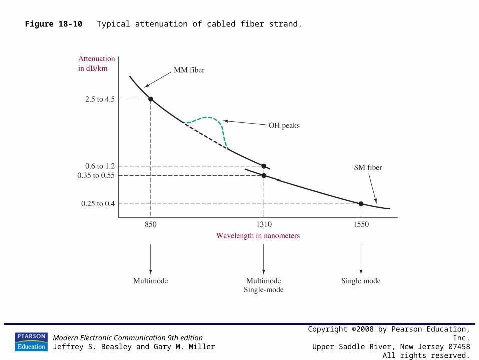
Figure 18-10 Typical attenuation of cabled fiber strand.
Modern Electronic Communication 9th editionJeffrey S. Beasley and Gary M. Miller
Copyright ©2008 by Pearson Education, Inc.Upper Saddle River, New Jersey 07458
All rights reserved.
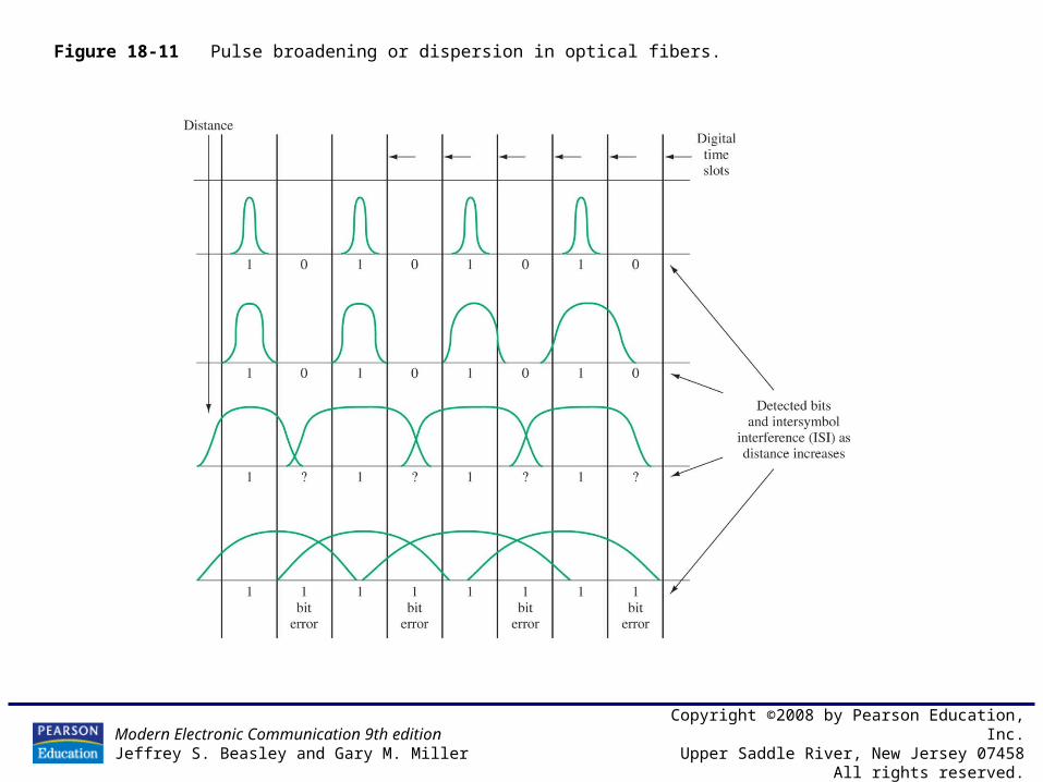
Figure 18-11 Pulse broadening or dispersion in optical fibers.
Modern Electronic Communication 9th editionJeffrey S. Beasley and Gary M. Miller
Copyright ©2008 by Pearson Education, Inc.Upper Saddle River, New Jersey 07458
All rights reserved.
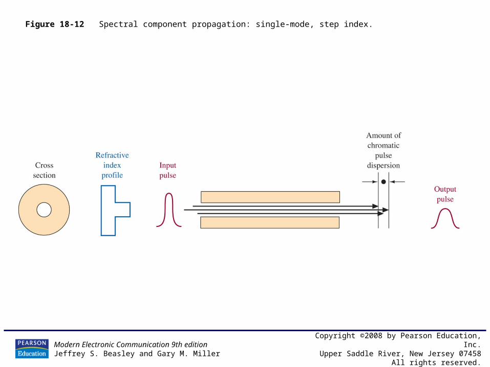
Figure 18-12 Spectral component propagation: single-mode, step index.

Modern Electronic Communication 9th editionJeffrey S. Beasley and Gary M. Miller
Copyright ©2008 by Pearson Education, Inc.Upper Saddle River, New Jersey 07458
All rights reserved.
Figure 18-13 Polarization mode dispersion in single-mode fiber.
Modern Electronic Communication 9th editionJeffrey S. Beasley and Gary M. Miller
Copyright ©2008 by Pearson Education, Inc.Upper Saddle River, New Jersey 07458
All rights reserved.
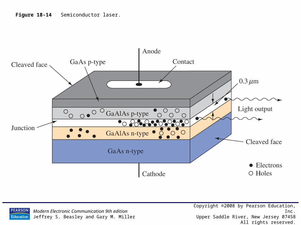
Figure 18-14 Semiconductor laser.
Modern Electronic Communication 9th editionJeffrey S. Beasley and Gary M. Miller
Copyright ©2008 by Pearson Education, Inc.Upper Saddle River, New Jersey 07458
All rights reserved.
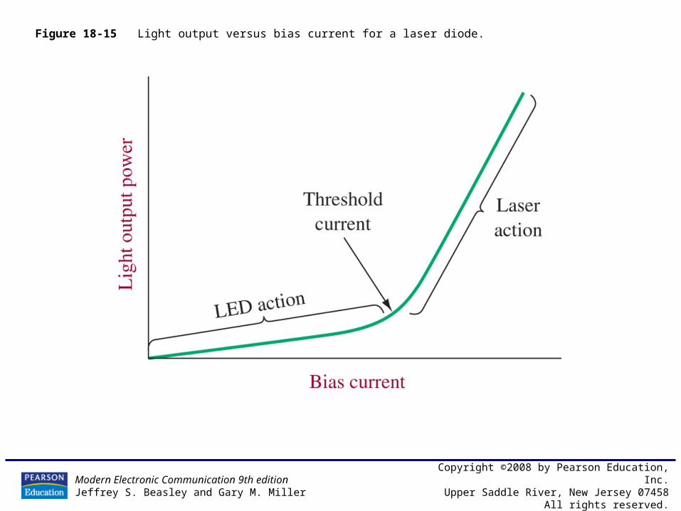
Figure 18-15 Light output versus bias current for a laser diode.
Modern Electronic Communication 9th editionJeffrey S. Beasley and Gary M. Miller
Copyright ©2008 by Pearson Education, Inc.Upper Saddle River, New Jersey 07458
All rights reserved.
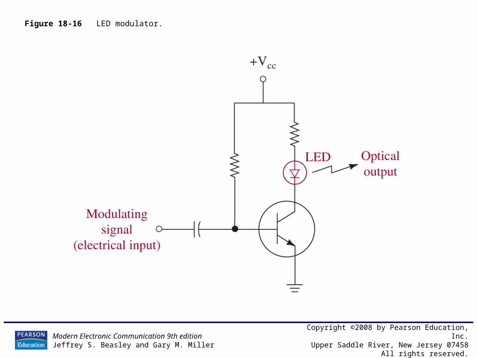
Figure 18-16 LED modulator.

Modern Electronic Communication 9th editionJeffrey S. Beasley and Gary M. Miller
Copyright ©2008 by Pearson Education, Inc.Upper Saddle River, New Jersey 07458
All rights reserved.
Figure 18-17 Spectral response of a p-i-n diode.

Modern Electronic Communication 9th editionJeffrey S. Beasley and Gary M. Miller
Copyright ©2008 by Pearson Education, Inc.Upper Saddle River, New Jersey 07458
All rights reserved.
Figure 18-18 p-i-n diode.
Modern Electronic Communication 9th editionJeffrey S. Beasley and Gary M. Miller
Copyright ©2008 by Pearson Education, Inc.Upper Saddle River, New Jersey 07458
All rights reserved.
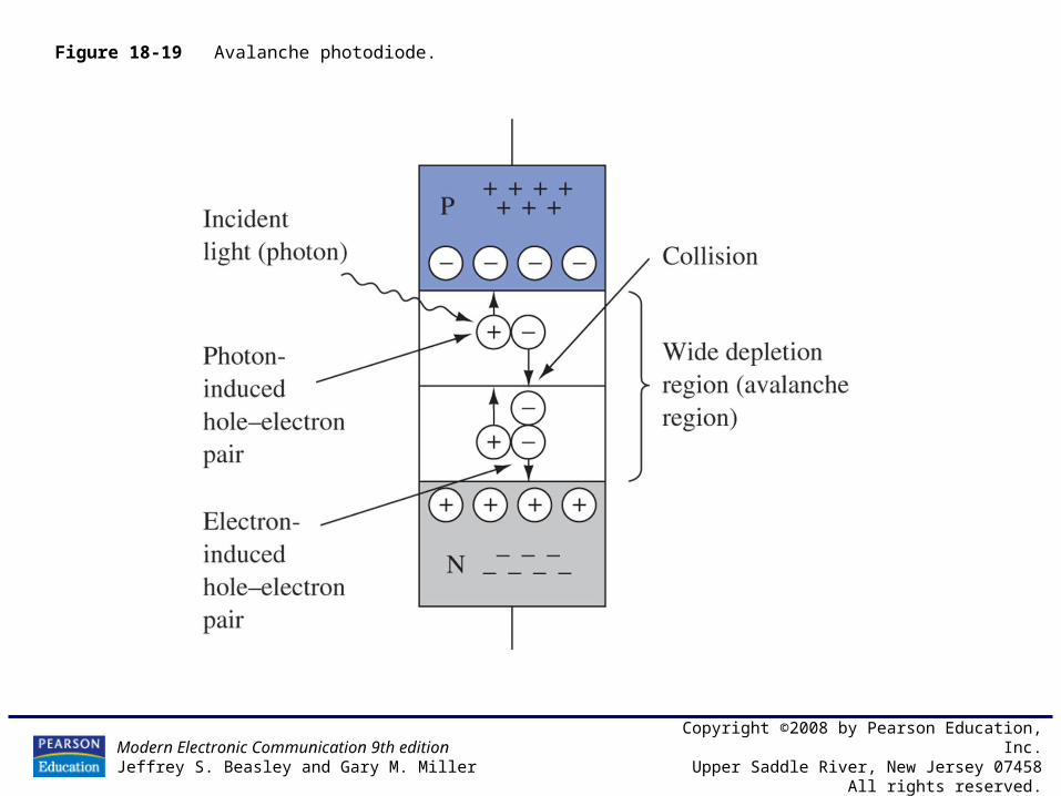
Figure 18-19 Avalanche photodiode.
Modern Electronic Communication 9th editionJeffrey S. Beasley and Gary M. Miller
Copyright ©2008 by Pearson Education, Inc.Upper Saddle River, New Jersey 07458
All rights reserved.
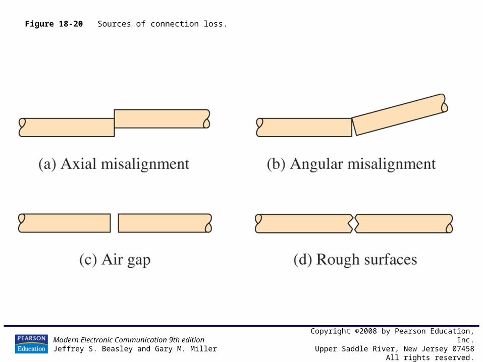
Figure 18-20 Sources of connection loss.

Modern Electronic Communication 9th editionJeffrey S. Beasley and Gary M. Miller
Copyright ©2008 by Pearson Education, Inc.Upper Saddle River, New Jersey 07458
All rights reserved.
Figure 18-20 (continued) Sources of connection loss.
Modern Electronic Communication 9th editionJeffrey S. Beasley and Gary M. Miller
Copyright ©2008 by Pearson Education, Inc.Upper Saddle River, New Jersey 07458
All rights reserved.
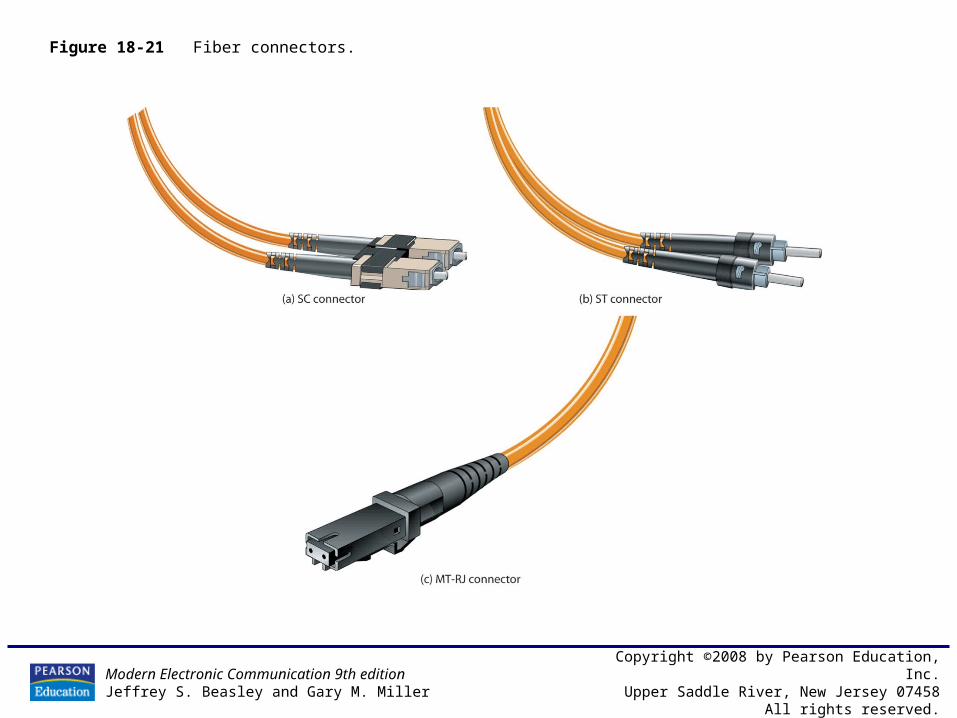
Figure 18-21 Fiber connectors.

Modern Electronic Communication 9th editionJeffrey S. Beasley and Gary M. Miller
Copyright ©2008 by Pearson Education, Inc.Upper Saddle River, New Jersey 07458
All rights reserved.
Figure 18-22 System design.
Modern Electronic Communication 9th editionJeffrey S. Beasley and Gary M. Miller
Copyright ©2008 by Pearson Education, Inc.Upper Saddle River, New Jersey 07458
All rights reserved.
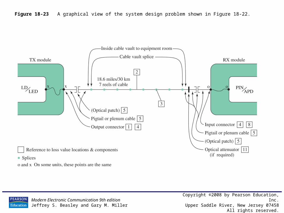
Figure 18-23 A graphical view of the system design problem shown in Figure 18-22.
Modern Electronic Communication 9th editionJeffrey S. Beasley and Gary M. Miller
Copyright ©2008 by Pearson Education, Inc.Upper Saddle River, New Jersey 07458
All rights reserved.
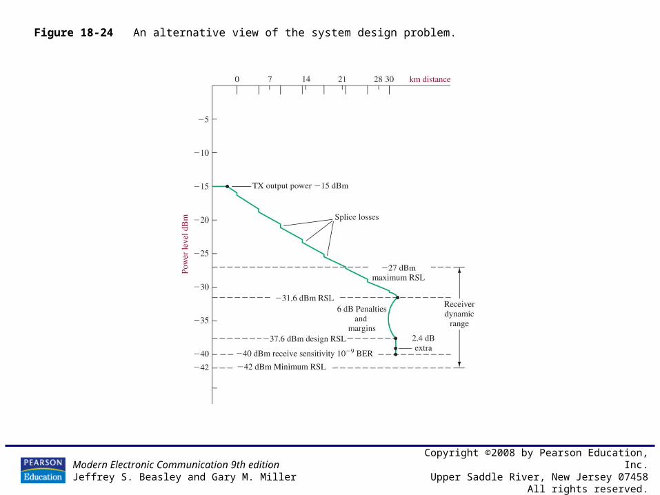
Figure 18-24 An alternative view of the system design problem.

Modern Electronic Communication 9th editionJeffrey S. Beasley and Gary M. Miller
Copyright ©2008 by Pearson Education, Inc.Upper Saddle River, New Jersey 07458
All rights reserved.
Figure 18-25 An OTDR trace of an 850-nm fiber.
Modern Electronic Communication 9th editionJeffrey S. Beasley and Gary M. Miller
Copyright ©2008 by Pearson Education, Inc.Upper Saddle River, New Jersey 07458
All rights reserved.
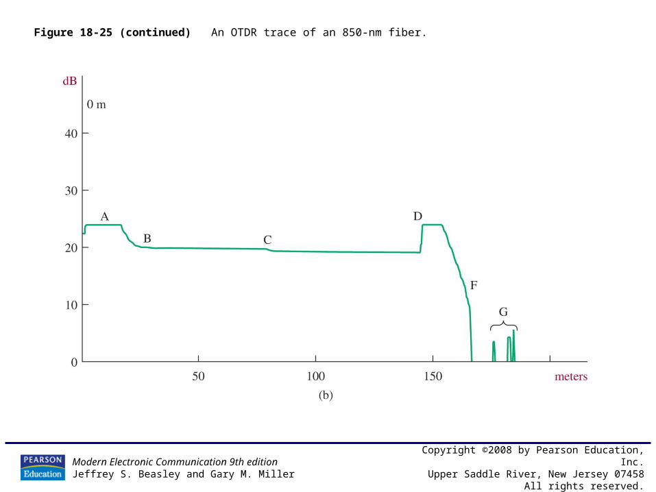
Figure 18-25 (continued) An OTDR trace of an 850-nm fiber.

Modern Electronic Communication 9th editionJeffrey S. Beasley and Gary M. Miller
Copyright ©2008 by Pearson Education, Inc.Upper Saddle River, New Jersey 07458
All rights reserved.
Figure 18-26 An example of connecting a PC to an Ethernet hub or switch via fiber.
Modern Electronic Communication 9th editionJeffrey S. Beasley and Gary M. Miller
Copyright ©2008 by Pearson Education, Inc.Upper Saddle River, New Jersey 07458
All rights reserved.
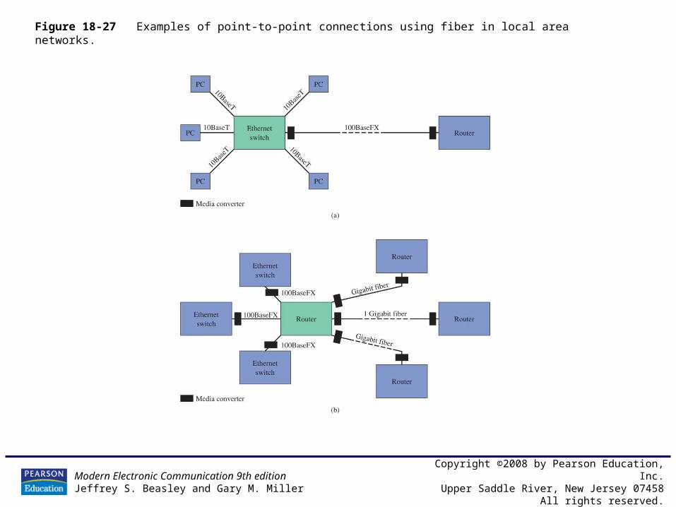
Figure 18-27 Examples of point-to-point connections using fiber in local area networks.
Modern Electronic Communication 9th editionJeffrey S. Beasley and Gary M. Miller
Copyright ©2008 by Pearson Education, Inc.Upper Saddle River, New Jersey 07458
All rights reserved.
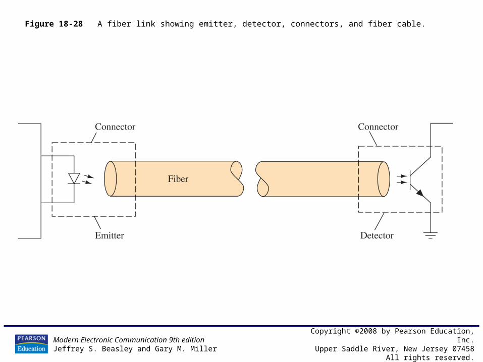
Figure 18-28 A fiber link showing emitter, detector, connectors, and fiber cable.

Modern Electronic Communication 9th editionJeffrey S. Beasley and Gary M. Miller
Copyright ©2008 by Pearson Education, Inc.Upper Saddle River, New Jersey 07458
All rights reserved.
Figure 18-29 Light probe.

Modern Electronic Communication 9th editionJeffrey S. Beasley and Gary M. Miller
Copyright ©2008 by Pearson Education, Inc.Upper Saddle River, New Jersey 07458
All rights reserved.
Figure 18-30 The Multisim circuit for the light-budget simulation.

Modern Electronic Communication 9th editionJeffrey S. Beasley and Gary M. Miller
Copyright ©2008 by Pearson Education, Inc.Upper Saddle River, New Jersey 07458
All rights reserved.
Figure 18-31 The settings for the voltage-controlled sine-wave generator that is being used to model an optical receiver with a minimum and maximum RSL.
Modern Electronic Communication 9th editionJeffrey S. Beasley and Gary M. Miller
Copyright ©2008 by Pearson Education, Inc.Upper Saddle River, New Jersey 07458
All rights reserved.
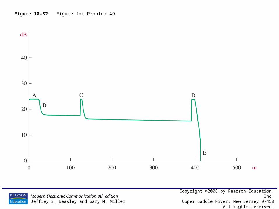
Figure 18-32 Figure for Problem 49.


