FieldPoint cFP-20xx Quick Start Guide - National · PDF filewith the backplane to secure the...
20
FieldPoint TM 1 cFP-20xx Quick Start Guide © National Instruments Corporation cFP-20xx Quick Start Guide What You Need to Get Set Up • cFP-20xx LabVIEW RT controller • Mounting hardware (DIN rail, panel-mount, or rack-mount accessory) • I/O module(s) • cFP-BP-x backplane, connector blocks, cables • 11–30 VDC power supply • Accessories: Ethernet cable, number 2 Phillips screwdriver • PC running Windows • FieldPoint software 3.0.2 or later • LabVIEW RT Mount the Compact FieldPoint Backplane You can mount the cFP-BP-x backplane on a 35 mm DIN rail, on a panel, or in a standard 19 in. rack. Before using any of these mounting methods, record the serial number from the back of the backplane. Each set of mounting instructions in this document includes an instruction to connect the protective earth (PE) ground terminal on the cFP-BP-x backplane to the system safety ground. The backplane PE ground terminal has the following symbol stamped beside it: . Connect the backplane PE ground terminal to the system safety ground using 14 AWG (1.6 mm) wire with a ring lug. Use the 5/16 in. panhead screw shipped with the backplane to secure the ring lug to the backplane PE ground terminal. 1
-
Upload
nguyenthien -
Category
Documents
-
view
216 -
download
2
Transcript of FieldPoint cFP-20xx Quick Start Guide - National · PDF filewith the backplane to secure the...
FieldPoint TM
1 cFP-20xx Quick Start Guide© National Instruments Corporation
cFP-20xx Quick Start Guide
What You Need to Get Set Up
• cFP-20xx LabVIEW RT controller• Mounting hardware (DIN rail,
panel-mount, or rack-mountaccessory)
• I/O module(s)• cFP-BP-x backplane, connector
blocks, cables
• 11–30 VDC power supply• Accessories: Ethernet cable,
number 2 Phillips screwdriver• PC running Windows• FieldPoint software 3.0.2 or later• LabVIEW RT
Mount the Compact FieldPoint BackplaneYou can mount the cFP-BP-x backplane on a 35 mm DIN rail, on a panel, or in astandard 19 in. rack. Before using any of these mounting methods, record the serialnumber from the back of the backplane.
Each set of mounting instructions in this document includes an instruction to connectthe protective earth (PE) ground terminal on the cFP-BP-x backplane to the systemsafety ground. The backplane PE ground terminal has the following symbol stampedbeside it: . Connect the backplane PE ground terminal to the system safety groundusing 14 AWG (1.6 mm) wire with a ring lug. Use the 5/16 in. panhead screw shippedwith the backplane to secure the ring lug to the backplane PE ground terminal.
1
323334c.qxd 4/3/2003 4:19 PM Page 1
2cFP-20xx Quick Start Guide ni.com
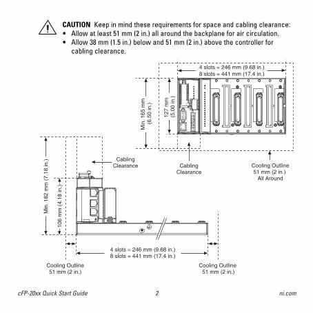
CAUTION Keep in mind these requirements for space and cabling clearance:• Allow at least 51 mm (2 in.) all around the backplane for air circulation.• Allow 38 mm (1.5 in.) below and 51 mm (2 in.) above the controller for
cabling clearance.
CablingClearance
4 slots = 246 mm (9.68 in.)8 slots = 441 mm (17.4 in.)
Cooling Outline51 mm (2 in.)
Cooling Outline 51 mm (2 in.)
Min
. 182
mm
(7.
18 in
.)
106
mm
(4.
18 in
.)
CablingClearance
Cooling Outline51 mm (2 in.)
All Around
4 slots = 246 mm (9.68 in.)8 slots = 441 mm (17.4 in.)
127
mm
(5.0
0 in
.)
Min
. 165
mm
(6
.50
in.)
323334c.qxd 4/3/2003 4:19 PM Page 2

3 cFP-20xx Quick Start Guide© National Instruments Corporation
Mounting the Backplane on a PanelA. Fasten the panel-mount plates to the back of the cFP-BP-x using a number 2 Phillips
screwdriver and the 8-32 × 5/16 in. countersink screws shipped with the kit.
CAUTION Do not use screws longer than 5/16 in. to fasten the panel-mountplates to the backplane.
NATIONAL
INSTRUMENTS
102 mm(4 in.)
457 mm (18 in.)
323334c.qxd 4/3/2003 4:19 PM Page 3

4cFP-20xx Quick Start Guide ni.com
260 mm (10.25 in.)
102 mm (4 in.)
104.78 mm (4.1 in.)
63.50 mm (2.5 in.)
22.23 mm (0.9 in.)
33.1
5 m
m(1
.3 in
.)
129.
54 m
m(5
.1 in
.)
311.
40 m
m(1
2.3
in.)
387.
60 m
m(1
5.3
in.)
407.
80 m
m(1
6.1
in.)
127.00 mm (5.0 in.)
440.94 mm(17.4 in.)
323334c.qxd 4/3/2003 4:19 PM Page 4
5 cFP-20xx Quick Start Guide© National Instruments Corporation
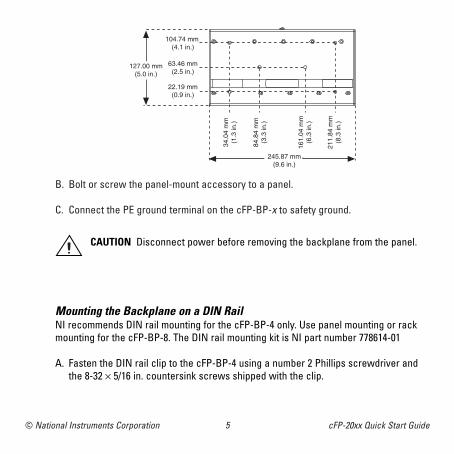
B. Bolt or screw the panel-mount accessory to a panel.
C. Connect the PE ground terminal on the cFP-BP-x to safety ground.
CAUTION Disconnect power before removing the backplane from the panel.
Mounting the Backplane on a DIN RailNI recommends DIN rail mounting for the cFP-BP-4 only. Use panel mounting or rackmounting for the cFP-BP-8. The DIN rail mounting kit is NI part number 778614-01
A. Fasten the DIN rail clip to the cFP-BP-4 using a number 2 Phillips screwdriver andthe 8-32 × 5/16 in. countersink screws shipped with the clip.
104.74 mm (4.1 in.)
63.46 mm(2.5 in.)
127.00 mm(5.0 in.)
22.19 mm(0.9 in.)
34.0
4 m
m(1
.3 in
.)
84.8
4 m
m(3
.3 in
.)
161.
04 m
m(6
.3 in
.)
211.
84 m
m(8
.3 in
.)
245.87 mm(9.6 in.)
323334c.qxd 4/3/2003 4:19 PM Page 5
6cFP-20xx Quick Start Guide ni.com
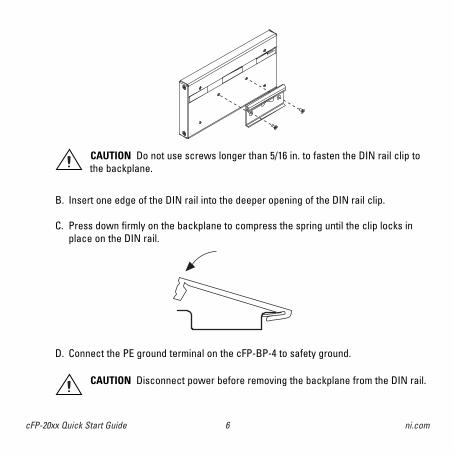
B. Insert one edge of the DIN rail into the deeper opening of the DIN rail clip.
C. Press down firmly on the backplane to compress the spring until the clip locks inplace on the DIN rail.
D. Connect the PE ground terminal on the cFP-BP-4 to safety ground.
CAUTION Disconnect power before removing the backplane from the DIN rail.
CAUTION Do not use screws longer than 5/16 in. to fasten the DIN rail clip tothe backplane.
NATIONAL
INSTRUMENTS
323334c.qxd 4/3/2003 4:19 PM Page 6

7 cFP-20xx Quick Start Guide© National Instruments Corporation
Mounting the Backplane in a Standard 19-in. RackA. Fasten the rack-mount bracket to the back of the cFP-BP-x using the captive
screws on the bracket.
NATIONAL
INSTRUMENTS
323334c.qxd 4/3/2003 4:19 PM Page 7

8cFP-20xx Quick Start Guide ni.com
B. Bolt the rack-mount accessory to a standard 19-in. rack.
C. Connect the PE ground terminal on the cFP-BP-x to safety ground.
NATIONAL
INSTRUMENTS
CAUTION Disconnect power before removing the backplane from the bracket.
323334c.qxd 4/3/2003 4:19 PM Page 8

9 cFP-20xx Quick Start Guide© National Instruments Corporation
Install the cFP-20xx Controller on the BackplaneA. Make sure that no power is connected to the controller.
B. Make sure that the cFP-20xx controller is right side up with the NI logo at the top,and align the captive screws on the controller with the holes on the backplane.
C. Seat the card edge at the back of the controller in the card-edge connector on thebackplane.
D. Press the controller firmly to seat it on the backplane.
E. Using a number 2 Phillips screwdriver with a shank of at least 64 mm (2.5 in.) length,tighten the captive screws to 1.1 N ⋅ m (10 lb ⋅ in.) of torque.
2
NATIONAL INSTRUMENTS
323334c.qxd 4/3/2003 4:19 PM Page 9

10cFP-20xx Quick Start Guide ni.com
Install I/O Modules on the BackplaneA. Align the captive screws on the I/O module with the holes on the backplane.
B. Press firmly to seat the I/O module on the backplane.
C. Using a number 2 Phillips screwdriver with a shank of at least 64 mm (2.5 in.) length,tighten the captive screws to 1.1 N ⋅ m (10 lb ⋅ in.) of torque.
D. Repeat this procedure to install additional I/O modules on the backplane.
3
323334c.qxd 4/3/2003 4:19 PM Page 10

11 cFP-20xx Quick Start Guide© National Instruments Corporation
Install Connector Blocks on the BackplaneIn order to connect I/O modules to input signals or to external loads, you need to installa cFP-CB-x connector block or other connectivity accessory for each I/O module onthe backplane. Use the connector socket to the right of each I/O module socket.
A. Wire field devices as described in the I/O module and connector block operatinginstructions.
B. Align the captive screws on the connector block with the holes on the backplane.
C. Press firmly to seat the connector block on the backplane.
D. Using a number 2 Phillips screw-driver with a shank of at least 64 mm (2.5 in.) length, tighten thecaptive screws to 1.1 N ⋅ m (10 lb ⋅ in.) of torque.
E. Repeat this procedure to install additional connector blocks on the backplane.
4
CAUTION Do not insert or remove connector blocks or other connectivityaccessories while power is applied to them.
CAUTION Hazardous voltage wiring should be performed by qualifiedpersonnel and in accordance with local electrical standards.
323334c.qxd 4/3/2003 4:19 PM Page 11

12cFP-20xx Quick Start Guide ni.com
Connect the cFP-20xx to Your NetworkConnect the cFP-20xx controller to an Ethernet network using the RJ-45 Ethernet porton the controller. Use a standard Category 5 Ethernet cable to connect the cFP-20xx toan Ethernet hub, or use an Ethernet crossover cable to connect the controller directlyto a computer.
If the host PC is already configured on a network, you must configure the cFP-20xx onthe same network. If neither is connected to a network, you can connect the twodirectly using a crossover cable.
In order for you to configure the cFP-20xx, it must reside on the same subnet as thehost PC.
5
CAUTION To prevent data loss and to maintain the integrity of your Ethernetinstallation, do not use a cable longer than 100 m. If you are using a 100 MbpsEthernet, National Instruments recommends using a Category 5 shieldedtwisted-pair Ethernet cable.
323334c.qxd 4/3/2003 4:19 PM Page 12

13 cFP-20xx Quick Start Guide© National Instruments Corporation
Wire Power to the Compact FieldPoint SystemEach cFP-20xx on your network requires an 11–30 VDC power supply.
A. Connect the positive lead of the primarypower supply to one of the V1 terminalsand the negative lead to one of the C terminals.
B. If you are using a backup power supply,connect the positive lead to V2 and thenegative lead to one of the C terminals.The cFP-20xx uses the power supply withthe higher voltage level. V2 is isolatedfrom the other V terminals.
C. Refer to the operating instructions for the power requirements of each I/O module.
D. Use a separate power supply for each module that needs external power.
6
C
V1
V2
+–
+–
11–30 VDCPrimary Power Supply
11–30 VDC BackupPower Supply
(optional)
CAUTION Cascading power defeats isolation between the cascaded modules.
323334c.qxd 4/3/2003 4:19 PM Page 13
14cFP-20xx Quick Start Guide ni.com
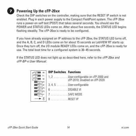
Powering Up the cFP-20xxCheck the DIP switches on the controller, making sure that the RESET IP switch is notenabled. Plug in each power supply to the Compact FieldPoint system. The cFP-20xxruns a power-on self test (POST) that takes several seconds. You should see thePOWER and STATUS LEDs come on. After about five seconds, the STATUS LED beginsflashing steadily. The cFP-20xx is ready to be configured.
If you have already assigned an IP address to the cFP-20xx, the STATUS LED turns off,and the A, B, C, and D LEDs come on for about 15 seconds as LabVIEW RT starts up.Once they turn off, the I/O module READY LEDs come on, and the cFP-20xx is ready foruse. The total boot time for a configured system is 30–45 seconds.
If the STATUS LED does not light up as described here, refer to the cFP-20xx and cFP-BP-x User Manual.
7
12
34
56
87
ON
DIP Switches Functions1, 2 . . . . . . . . . .User-configurable on cFP-2000 and
cFP-2010; disabled on cFP-20203, 4, 5 . . . . . . . .User-configurable6 . . . . . . . . . . . .DISABLE VI7 . . . . . . . . . . . .SAFE MODE8 . . . . . . . . . . . .RESET IP
323334c.qxd 4/3/2003 4:19 PM Page 14

15 cFP-20xx Quick Start Guide© National Instruments Corporation
Install Software on the Host PCA. Install the software packages you plan to use, such as LabVIEW, LabVIEW RT,
Measurement Studio, VI Logger, or LabWindowsTM/CVITM, before you install theFieldPoint software. The FieldPoint software installation installs the LabVIEW VIsand examples and the LabWindows/CVI instrument driver only if it finds thecorresponding development software installed.
B. Close all other applications.
C. Insert the National Instruments FieldPoint Software CD into the CD-ROM drive onyour computer.
D. Follow the onscreen instructions to complete the installation.
8
NOTE If the setup does not launch automatically, select Start»Run fromWindows, enter d:\setup, where d is the letter of your CD-ROM drive, andselect OK.
Configure the cFP-20xxLaunch Measurement & Automation Explorer (MAX) to configure the cFP-20xx. Forinformation about configuring the cFP-20xx in software, refer to the Measurement &Automation Explorer Help for FieldPoint (Start»Programs»National Instruments»FieldPoint»FieldPoint Help).
9
323334c.qxd 4/3/2003 4:19 PM Page 15

16cFP-20xx Quick Start Guide ni.com
Specifications
NetworkNetwork interface . . . . . . . . . . . . . . . 10BaseT and 100BaseTX EthernetCompatibility. . . . . . . . . . . . . . . . . . . . IEEE802.3Communication rates . . . . . . . . . . . . 10 Mbps, 100 Mbps, auto-negotiatedMaximum cabling distance . . . . . . . 100 m/segmentMaximum power to connected I/O modules . . . . . . . . 9 WMaximum number of banks . . . . . . . Determined by network topology
MemorycFP-2000 . . . . . . . . . . . . . . . . . . . . . . . 16 MB nonvolatile; 16 MB DRAMcFP-2010 . . . . . . . . . . . . . . . . . . . . . . . 32 MB nonvolatile; 32 MB DRAMcFP-2020 . . . . . . . . . . . . . . . . . . . . . . . 32 MB nonvolatile; 32 MB DRAMFor information about the memory used by the LabVIEW RT module and the operatingsystem, go to ni.com/info and enter rdfpec.
RS-485 Isolation VoltageMaximum isolation voltage. . . . . . . . 100 VrmsTransient overvoltage . . . . . . . . . . . . 740 Vrms
Power RequirementPower supply range . . . . . . . . . . . . . 11 to 30 VDCRecommended power supply
cFP-BP-4 system . . . . . . . . . . . 15 WcFP-BP-8 system . . . . . . . . . . . 20 W
323334c.qxd 4/3/2003 4:19 PM Page 16

17 cFP-20xx Quick Start Guide© National Instruments Corporation
Power consumptioncFP-2000 . . . . . . . . . . . . . . . . . . 4.8 W + 1.1(I/O module power requirements)cFP-2010 . . . . . . . . . . . . . . . . . . 5.0 W + 1.1(I/O module power requirements)cFP-2020 . . . . . . . . . . . . . . . . . . 6.1 W + 1.1(I/O module power requirements)
Physical CharacteristicsScrew-terminal wiring . . . . . . . . . . . 16–26 AWG copper conductor wire with
7 mm (0.28 in.) of insulation stripped from the endTorque for screw terminals . . . . . . . 0.5–0.6 N ⋅ m (4.4–5.3 lb ⋅ in.)Weight of cFP-20xx . . . . . . . . . . . . . . 278 g (9.8 oz)
EnvironmentalFieldPoint modules are intended for indoor use only. For outdoor use, they must be installed ina suitable sealed enclosure.Operating temperature . . . . . . . . . . . –25 to 60 °CStorage temperature . . . . . . . . . . . . . –55 to 85 °C Humidity . . . . . . . . . . . . . . . . . . . . . . . 10 to 90% RH, noncondensingMaximum altitude . . . . . . . . . . . . . . . 2,000 m; at higher altitudes the isolation voltage ratings
must be loweredPollution Degree . . . . . . . . . . . . . . . . 2
Shock and VibrationOperating vibration
Random (IEC 60068-2-64). . . . . 10–500 Hz, 5 grmsSinusoidal (IEC 60068-2-6) . . . . 10–500 Hz, 5 g
Operating shock (IEC 60068-2-27) . . . . . . . . . . . . . . . . . 50 g, 3 ms half sine, 18 shocks at 6 orientations;
30 g, 11 ms half sine, 18 shocks at 6 orientations
323334c.qxd 4/3/2003 4:19 PM Page 17

18cFP-20xx Quick Start Guide ni.com
SafetyThis product is designed to meet the requirements of the following standards of safetyfor electrical equipment for measurement, control, and laboratory use:• IEC 61010-1, EN 61010-1• UL 3121-1, UL 61010C-1• CAN/CSA C22.2 No. 1010.1For UL, hazardous location, and other safety certifications, refer to the product label orto ni.com.
Electromagnetic CompatibilityCE, C-Tick, and FCC Part 15 (Class A) CompliantEmissions . . . . . . . . . . . . . . . . . . . . . . EN 55011 Class A at 10 m FCC Part 15A
above 1 GHzImmunity . . . . . . . . . . . . . . . . . . . . . . . EN 61326:1997 + A2:2002, Table 1
For EMC compliance, operate this device with shielded cabling.
CE ComplianceThis product meets the essential requirements of applicable European Directives, asamended for CE Marking, as follows:Low-Voltage Directive (safety) . . . . . 73/23/EECElectromagnetic Compatibility Directive (EMC). . . . . . 89/336/EEC
NOTE Refer to the Declaration of Conformity (DoC) for this product foradditional regulatory compliance information. To obtain the DoC for thisproduct, click Declarations of Conformity Information atni.com/hardref.nsf/.
323334c.qxd 4/3/2003 4:19 PM Page 18

19 cFP-20xx Quick Start Guide© National Instruments Corporation
CablingThe table below shows the standard Ethernet cable wiring connections for both normaland crossover cables.
Connector 1 Connector 2
pin 1 pin 1 pin 8pin 8
Ethernet CableConnector Pinouts
1 white/orange white/orange white/green
2 orange orange green
3 white/green white/green white/orange
4 blue blue blue
5 white/blue white/blue white/blue
6 green green orange
7 white/brown white/brown white/brown
8 brown brown brown
Connector 2 Connector 2Pin Connector 1 (Normal) (Crossover)
323334c.qxd 4/3/2003 4:19 PM Page 19

Go to ni.com/support for the most current manuals, examples, and troubleshooting information. For telephone support in the United States, create your service request at ni.com/ask and follow thecalling instructions or dial 512 795 8248. For telephone support outside the United States, contact yourlocal branch office:
Australia 02 612 9672 8846, Austria 43 0 662 45 79 90 0, Belgium 32 0 2 757 00 20, Brazil 55 11 3262 3599, Canada (Calgary) 403 274 9391, Canada (Montreal) 514 288 5722, Canada (Ottawa) 613 233 5949, Canada (Québec) 514 694 8521, Canada (Toronto) 905 785 0085, Canada (Vancouver) 514 685 7530, China 86 21 6555 7838, Czech Republic 420 2 2423 5774, Denmark 45 45 76 26 00, Finland 385 0 9 725 725 11,France 33 0 1 48 14 24 24, Germany 49 0 89 741 31 30, Greece 30 2 10 42 96 427, Hong Kong 2645 3186, India 91 80 51190000, Israel 972 0 3 6393737, Italy 39 02 413091, Japan 81 3 5472 2970, Korea 82 02 3451 3400,Malaysia 603 9131 0918, Mexico 001 800 010 0793, Netherlands 31 0 348 433 466, New Zealand 64 09 914 0488,Norway 47 0 32 27 73 00, Poland 48 0 22 3390 150, Portugal 351 210 311 210, Russia 7 095 238 7139,Singapore 65 6226 5886, Slovenia 386 3 425 4200, South Africa 27 0 11 805 8197, Spain 34 91 640 0085,Sweden 46 0 8 587 895 00, Switzerland 41 56 200 51 51, Taiwan 886 2 2528 7227, United Kingdom 44 0 1635 523545
CVITM, FieldPointTM, LabVIEWTM, Measurement StudioTM, National InstrumentsTM, NITM, and ni.comTM aretrademarks of National Instruments Corporation. Product and company names mentioned herein aretrademarks or trade names of their respective companies.
For patents covering National Instruments products, refer to the appropriate location: Help»Patents in your software, the patents.txt file on your CD, or ni.com/patents.
© 2002–2003 National Instruments Corporation. All rights reserved.373334C-01 Apr03
ni.com
323334c.qxd 4/3/2003 4:19 PM Page 20