
Fiber Optic Terminus End Face Quality · PDF fileFiber Optic Terminus End Face Quality...
12
Fiber Optic Terminus End Face Quality Standards Introduction Good fiber optic performance relies on connectors that are manufactured properly. Specifically, optimal optical performance requires that the mating surfaces of the fiber optic termini be polished in accordance with industry standards for geometry and cleanliness. This paper briefly explains and addresses those requirements. Fiber Construction Figure 1 - Representation of a Fiber Optic Cable Figure 1 depicts a representative cross-section of a single mode fiber optic cable. The outer jacket provides protection from environmental elements while the buffer provides pull strength to the fragile core/cladding. A typical outer diameter of the glass or cladding of fiber optic cable measures 125um, just slightly larger than that of the average human hair of 100um. For demonstration purposes, the cladding in Figure 1 is depicted as recessed back from the core; in reality, the core and cladding are cut at the same length and it is impossible to distinguish between the two with the human eye. Fiber to Fiber Connection Options The fiber is the conducting medium through which a light signal passes from the transmitter to the receiver. A connector terminates the optical fiber inside a ceramic ferrule with the use of epoxy to hold the fiber in place and allows mating/de-mating of he fiber optic circuit. t Fiber termination begins with removing the appropriate length of outer jacket to expose the buffer. The buffer is next stripped to the appropriate length to expose the core/cladding, which in turn is cleaned. The exposed core/cladding is then inserted through the ferrule, the internal fiber passageway of which has been filled with epoxy. Finally, the epoxy is “cured” at a specified time and temperature to complete the process. 1
Transcript of Fiber Optic Terminus End Face Quality · PDF fileFiber Optic Terminus End Face Quality...

Fiber Optic Terminus End Face Quality Standards
Introduction Good fiber optic performance relies on connectors that are manufactured properly. Specifically, optimal optical performance requires that the mating surfaces of the fiber optic termini be polished in accordance with industry standards for geometry and cleanliness. This paper briefly explains and addresses those requirements. Fiber Construction
Figure 1 - Representation of a Fiber Optic Cable
Figure 1 depicts a representative cross-section of a single mode fiber optic cable. The outer jacket provides protection from environmental elements while the buffer provides pull strength to the fragile core/cladding. A typical outer diameter of the glass or cladding of fiber optic cable measures 125um, just slightly larger than that of the average human hair of 100um. For demonstration purposes, the cladding in Figure 1 is depicted as recessed back from the core; in reality, the core and cladding are cut at the same length and it is impossible to distinguish between the two with the human eye. Fiber to Fiber Connection Options The fiber is the conducting medium through which a light signal passes from the transmitter to the receiver. A connector terminates the optical fiber inside a ceramic ferrule with the use of epoxy to hold the fiber in place and allows mating/de-mating of he fiber optic circuit. t Fiber termination begins with removing the appropriate length of outer jacket to expose the buffer. The buffer is next stripped to the appropriate length to expose the core/cladding, which in turn is cleaned. The exposed core/cladding is then inserted through the ferrule, the internal fiber passageway of which has been filled with epoxy. Finally, the epoxy is “cured” at a specified time and temperature to complete the process.
1

At this point the fiber is held in place by the terminus. The excess fiber is then removed from the end of the terminus and the appropriate polish finish applied. To join or mate each fiber with its respective opposing terminus, the termini are held in direct physical contact (PC) and aligned using a sleeve. This process is repeatable, cost-effective and produces a product that is easy to clean. Figure 2 shows an example of resultant termini and alignment sleeve representative of the process just described.
Figure 2 - Zirconia Sleeve Between Simplex Fiber Terminations
Fiber with outer jacket
Requirements for Fiber to Fiber Connections The telecommunications industry was an early adopter and high volume consumer of fiber optic cable; consequently, quality requirements were first established by this industry. Performance tests were developed to analyze optical connectors across various operating conditions. Generic requirements (GR) were defined across the following five categories:
1) General Requirements – covering documentation, packaging and design features;
2) Performance Requirements – including service life and long term reliability; 3) Service Life – testing to simulate stresses to which a connector could be
subjected; 4) Reliability Tests – providing for long term reliability; 5) Reliability Assurance – ensuring desired long-term operation of fiber optic
connectors.
These product concerns and guiding requirements were published in a Telecordia document known as GR-326-CORE. The development of these requirements and collection of data resulted in terminus geometry requirements that are summarized in Table 1 below.
GR 326
Terminus Geometry Requirements (Single
Ferrule
Terminus
Sleeve
2

Mode) Terminus Type
Radius of Curvature
Fiber Height Apex Offset
Physical Contact
7 to 25mm +50nm to -125nm <50um
Angled Physical Contact
7 to 12mm +100nm to -100nm < 50um
Table 1 – GR 326 Terminus and Fiber Geometry Requirements for Single Mode
Expanded Terminus and Fiber Geometry Requirement for Single Mode and Multimode The aerospace industry similarly developed its own guidelines in a comprehensive standard entitled Aerospace Standard 5675. It defines a measurable for single mode termination, 9/125um and it includes a measurable for multimode terminations as well. It also establishes “Grade A” and “Grade B” categories. The distinguishing characteristics between the two grades are the reduced range of the radius of curvature and the apex offset. AFSI uses the Aerospace Standard 5675 because our company believes this guideline ensures fiber optic terminations that yield the best optical performance, reliability, product life and quality. AS 5675 is shown below in Table 2.
3

Table 2 - Aerospace Standard 5675 for PC Termini
Ideal Terminus Geometry and Potential Scenarios to Avoid Best optical performance is achieved when the terminus is manufactured in accordance with the standard polishing process and to the desired end face geometries. Examples of terminus polish geometries and mechanical tolerances along with the resultant impacts to Insertion Loss (IL) and Return Loss (RL) are depicted in Table 3 below.
4

Table 3 - Terminus Geometries and the Impact to Insertion Loss and Return Loss
5

Terminus and Fiber Measured Physical Features
Figure 3 - Terminus Physical Features Figure 3 shows the features and parameters that need to be measured and controlled during the polishing process to provide the best optical performance.
Radius of Curvature (or Radius) is the corresponding radius of a circle that could be placed over the ferrule and match the curvature of the end of the ferrule. A nearly flat end face would have a very large radius of curvature because the corresponding circle would need to be very large to approximate the flat end face. A small radius of curvature would require a small circle, and the ferrule shape would resemble a pencil point. Fiber Undercut (or Protrusion) is measured in one of two approaches -- planar or spherical. The planar method has all but been abandoned by the industry, and it is derived from defining the location of the inside of the ferrule where the fiber passage way stops inside at the end. A virtual planar surface would be established across that location, and the height of the fiber would be obtained by measuring from the defined planar surface to the top of the fiber. Spherical fiber height is slightly different in that the curvature is interpolated from the known curvature of the ferrule into the space where the fiber exists. The fiber height is then measured from the virtual sphere to the known location of the core/cladding. End Face Angle is the measurement of the angle that exists between the perpendicular to the optical axis and the angle of the end face of the ferrule.
6

Apex Offset is defined as the distance of the location of high point of the ferrule with respect to the optical axis
Measurement Regions of Terminus and Fiber End Face An additional guiding requirement defines the regions or areas on the terminus and fiber end face where measurements are taken for radius of curvature, fiber height and apex offset (see Figure 4). This requirement ensures that when measurements are taken by different parties, the data is meaningful to all involved.
Figure 4 - Terminus and Fiber Measurement Regions
Optical Inspection of Terminus and Fiber End Face Meeting the terminus and fiber measureable features is a necessary but insufficient condition to ensure optimal optical performance. Fiber optic terminations are sensitive not only to the physical end face geometries but also to dust, dirt, debris and scratches across the fiber and areas on the ferrule close to the fiber. Published standards guide producers and users regarding the finish quality of the terminus. Tables 4 and 5 below show the acceptance criteria of IPC 8497 and AS 5675.
7
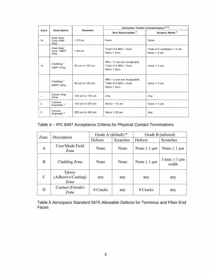
Table 4 – IPC 8497 Acceptance Criteria for Physical Contact Terminations
Grade A (default) * Grade B (tailored) Zone Description Defects Scratches Defects Scratches
A Core/Mode Field Zone None None None ≥ 1 μm None ≥ 1 μm
B Cladding Zone None None None ≥ 1 μm 3 max ≥ 1 μm width
C Epoxy
(Adhesive/Coating) Zone
any any any any
D Contact (Ferrule) Zone 0 Cracks any 0 Cracks any
Table 5 Aerospace Standard 5675 Allowable Defects for Terminus and Fiber End Faces
8

Figure 5 - Video Display of Ferrule and Fiber End Face Implementing these inspection/acceptance criteria in the factory requires special equipment. The system shown in Figure 5 is a bench- top microscope connected to a video display that provides a real-time image. This visual system is manual in nature and relies on human judgment. Therein lies a weakness to this approach -- what is deemed acceptable by one operator may not be acceptable by the next or a defect may be overlooked altogether. There are also automated systems (see Figure 6) that use defined criteria in conjunction with a computer running inspection software that applies the standards in an objective manner across defined regions of the fiber and terminus.
9

Figure 6 - Video Display of Objective Evaluation of the Terminus and Fiber End Face
Single Mode Multimode Figure 7
Figure 7 depicts a typical end face of single mode and multimode terminus and fiber end face regions. The closer one is to the core or region A, the more stringent the requirements are for a pristine condition.
10

The image of the inspection microscope is captured and the computer software then applies standards to each of the defined regions. Table 4, shown earlier, contains the list of acceptance criteria as defined by IPC 8497, which is often used in industry. The inspection software can be configured to apply the acceptance criteria to the defined regions and yield an objective decision regarding the quality of the terminus and fiber end face. AFSI uses the IPC 8497 end face definition standard. It does not permit any scratches in Zone A for single mode fiber while AS 5675 allows scratches for Grade B material. All U.S. government/ aerospace applications require Grade A end face inspection criteria under AS 5675. AFSI believes it is best not to permit any scratches in Zone A to insure best optical performance, reliability, product life and quality.
11

Company Overview
Amphenol Fiber Systems International (AFSI), a division of Amphenol, provides reliable and innovative fiber optic interconnect solutions that withstand the harsh environments of military (ground systems, avionics, shipboard), energy and broadcast applications. After more than 18 years in business, AFSI maintains its position as a global leader in fiber optic interconnect components and systems such as termini, M28876, 38999 assemblies, MIL-ST, TFOCA and the TFOCA-II® connector, which AFSI developed and patented. AFSI has delivered millions of fiber optic connectors in more than 34 countries. Whenever there is a need for superior cost-effective fiber optic systems and products that will stand up to demanding operating environments, you can rely on AFSI for engineering know-how, top-quality products and expert technical support.
Amphenol Fiber Systems International 1300 Central Expressway N, #100
Allen, TX 75013 T: (214) 547-2400 F: (214) 547-9344
About the author:
Phillip Herman, Advanced Manufacturing & Test Engineering Manager Phillip began his professional career in laser electro-optics working with excimer, tunable dye and Nd: YAG lasers, which were used by major universities, research facilities, NASA, NIST, the Air Force and NRL. Phillip worked briefly with Lockheed Space and Science at the Johnson Space Center in the Inertial Navigation Laboratory before joining Texas Instruments, where he spent 14 years working in the semiconductor manufacturing sector as a process and equipment engineer in Photolithography and later as the manager of Photolithography and Metrology equipment engineering. Phillip joined AFSI in 2009 and has focused efforts on continual improvement, waste reduction and improved productivity to bring greater differentiation of AFSI’s products in the market. Phillip graduated from the University of Houston Clear Lake with a Bachelor of Science in Applied Physics.
12


