Fiber-Optic Propagation Effects in Long-Haul … · Naval Research Laboratory Washington, DC...
22
Naval Research Laboratory Washington, DC 20375-5320 NRL/MR/5650--14-9537 Fiber-Optic Propagation Effects in Long-Haul HF/VHF/UHF Analog Photonic Links April 17, 2014 Approved for public release; distribution is unlimited. CHRISTOPHER E. SUNDERMAN VINCENT J. URICK Photonics Technology Branch Optical Sciences Division
Transcript of Fiber-Optic Propagation Effects in Long-Haul … · Naval Research Laboratory Washington, DC...
Naval Research LaboratoryWashington, DC 20375-5320
NRL/MR/5650--14-9537
Fiber-Optic Propagation Effects inLong-Haul HF/VHF/UHF AnalogPhotonic Links
April 17, 2014
Approved for public release; distribution is unlimited.
Christopher e. sunderman VinCent J. uriCk
Photonics Technology BranchOptical Sciences Division

i
REPORT DOCUMENTATION PAGE Form ApprovedOMB No. 0704-0188
3. DATES COVERED (From - To)
Standard Form 298 (Rev. 8-98)Prescribed by ANSI Std. Z39.18
Public reporting burden for this collection of information is estimated to average 1 hour per response, including the time for reviewing instructions, searching existing data sources, gathering and maintaining the data needed, and completing and reviewing this collection of information. Send comments regarding this burden estimate or any other aspect of this collection of information, including suggestions for reducing this burden to Department of Defense, Washington Headquarters Services, Directorate for Information Operations and Reports (0704-0188), 1215 Jefferson Davis Highway, Suite 1204, Arlington, VA 22202-4302. Respondents should be aware that notwithstanding any other provision of law, no person shall be subject to any penalty for failing to comply with a collection of information if it does not display a currently valid OMB control number. PLEASE DO NOT RETURN YOUR FORM TO THE ABOVE ADDRESS.
5a. CONTRACT NUMBER
5b. GRANT NUMBER
5c. PROGRAM ELEMENT NUMBER
5d. PROJECT NUMBER
5e. TASK NUMBER
5f. WORK UNIT NUMBER
2. REPORT TYPE1. REPORT DATE (DD-MM-YYYY)
4. TITLE AND SUBTITLE
6. AUTHOR(S)
8. PERFORMING ORGANIZATION REPORT NUMBER
7. PERFORMING ORGANIZATION NAME(S) AND ADDRESS(ES)
10. SPONSOR / MONITOR’S ACRONYM(S)9. SPONSORING / MONITORING AGENCY NAME(S) AND ADDRESS(ES)
11. SPONSOR / MONITOR’S REPORT NUMBER(S)
12. DISTRIBUTION / AVAILABILITY STATEMENT
13. SUPPLEMENTARY NOTES
14. ABSTRACT
15. SUBJECT TERMS
16. SECURITY CLASSIFICATION OF:
a. REPORT
19a. NAME OF RESPONSIBLE PERSON
19b. TELEPHONE NUMBER (include areacode)
b. ABSTRACT c. THIS PAGE
18. NUMBEROF PAGES
17. LIMITATIONOF ABSTRACT
Fiber-Optic Propagation Effects in Long-Haul HF/VHF/UHFAnalog Photonic Links
Christopher E. Sunderman and Vincent J. Urick
Naval Research Laboratory4555 Overlook Avenue, SWWashington, DC 20375-5320 NRL/MR/5650--14-9537
Approved for public release; distribution is unlimited.
UnclassifiedUnlimited
UnclassifiedUnlimited
UnclassifiedUnlimited
UnclassifiedUnlimited
21
Christopher Sunderman
(202) 404-7591
Fiber opticsAnalog photonics
A full theoretical analysis of crosstalk in fiber optic wavelength division multiplexed systems is presented for the HF/VHF/UHF (1 MHz to 3 GHz) frequency bands. Crosstalk due to both stimulated Raman scattering and cross-phase modulation is examined. Data is presented that shows the limitations these mechanisms can have on system dynamic range at these frequencies.
17-04-2014 Memorandum
Office of Naval ResearchOne Liberty Center875 North Randolph Street, Suite 1425Arlington, VA 22203-1995
EW-271-003
6582
ONR
Wavelength division multiplexingCrosstalk
05-03-2013 – 20-08-2014

TABLE OF CONTENTS
EXECUTIVE SUMMARY…………………………………………………………………. E-1
1 INTRODUCTION…………………………………….………………………………….. 1
2 DOUBLE RAYLEIGH SCATTERING………………………………………….……… 3
3 INTERCHANNEL CROSSTALK CALCULATIONS………….………..….…………. 5
3.1 Stimulated Raman Scattering (SRS)..…………………….……………………….. 5
3.2 Cross-phase Modulation (XPM)……………………………….…………………… 7
4 CROSSTALK MEASUREMENTS…..…..………………………………………..……. 10
5 SRS AND XPM IMPACT ON HF/VHF/UHF LINKS..…………………….………….. 15
6 CONCLUDING REMARKS……….….…………………………………….………….. 16
REFERENCES……………………………..…………………………………………….… 17
iii
EXECUTIVE SUMMARY The effect of crosstalk due to Stimulated Raman Scattering and Cross Phase Modulation in HF/VHF/UHF photonic links is examined. A theoretical model and experimental data each of the three bands under the constraint of a two wavelength system. The results presented in this report show that maintaining the dynamic range of a photonic link at these frequencies will be quite difficult. This will prove especially true for the HF/VHF bands where the WDM filter is shown to be the dominant crosstalk mechanism.
E-1
FIBER-OPTIC PROPAGATION EFFECTS IN LONG-HAUL HF/VHF/UHF ANALOG PHOTONIC LINKS
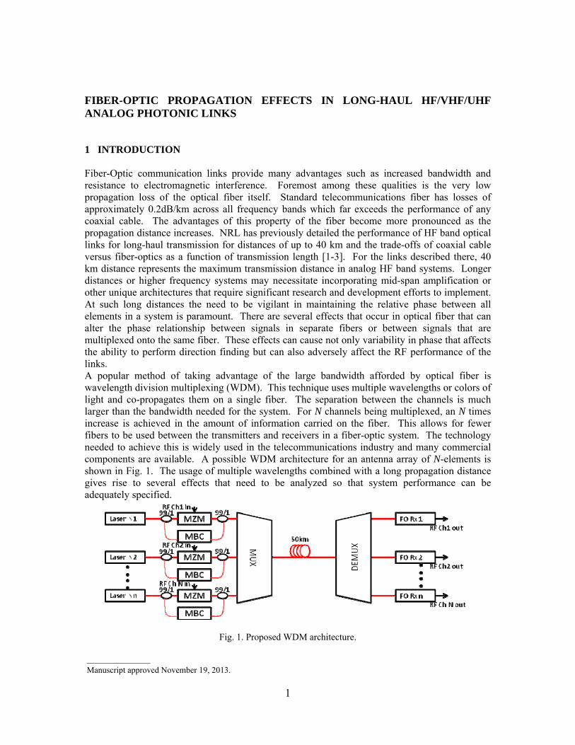
1 INTRODUCTION Fiber-Optic communication links provide many advantages such as increased bandwidth and resistance to electromagnetic interference. Foremost among these qualities is the very low propagation loss of the optical fiber itself. Standard telecommunications fiber has losses of approximately 0.2dB/km across all frequency bands which far exceeds the performance of any coaxial cable. The advantages of this property of the fiber become more pronounced as the propagation distance increases. NRL has previously detailed the performance of HF band optical links for long-haul transmission for distances of up to 40 km and the trade-offs of coaxial cable versus fiber-optics as a function of transmission length [1-3]. For the links described there, 40 km distance represents the maximum transmission distance in analog HF band systems. Longer distances or higher frequency systems may necessitate incorporating mid-span amplification or other unique architectures that require significant research and development efforts to implement. At such long distances the need to be vigilant in maintaining the relative phase between all elements in a system is paramount. There are several effects that occur in optical fiber that can alter the phase relationship between signals in separate fibers or between signals that are multiplexed onto the same fiber. These effects can cause not only variability in phase that affects the ability to perform direction finding but can also adversely affect the RF performance of the links. A popular method of taking advantage of the large bandwidth afforded by optical fiber is wavelength division multiplexing (WDM). This technique uses multiple wavelengths or colors of light and co-propagates them on a single fiber. The separation between the channels is much larger than the bandwidth needed for the system. For N channels being multiplexed, an N times increase is achieved in the amount of information carried on the fiber. This allows for fewer fibers to be used between the transmitters and receivers in a fiber-optic system. The technology needed to achieve this is widely used in the telecommunications industry and many commercial components are available. A possible WDM architecture for an antenna array of N-elements is shown in Fig. 1. The usage of multiple wavelengths combined with a long propagation distance gives rise to several effects that need to be analyzed so that system performance can be adequately specified.
Fig. 1. Proposed WDM architecture.
1
_______________Manuscript approved November 19, 2013.

Figure 2. An example of Four Wave Mixing in optical fiber.
Propagation effects in fiber range from linear scattering mechanisms to relatively complicated nonlinear processes. The linear process of Rayleigh scattering, due to the elastic scattering of a photon from an atom or molecule, is the dominant loss mechanism in fiber at 1550nm. Previous reports have addressed other phenomena such as phase drift due to temperature in long fiber lengths as well as the effects of chromatic dispersion resulting from the frequency dependent index of refraction of the optical fiber for HF applications [1]. Optical fiber is an inherently nonlinear medium as a consequence of its composition, the manufacturing processes used to produce it, and the nature of its usage. An example of this is four wave mixing (FWM) where two different wavelengths of light interact to produce two other wavelengths. This is analogous to third order intermodulation distortion in RF systems where two tones can combine to form distortion. Generally, the passage of light through the fiber medium induces a polarization in the fiber that has a nonlinear dependence on the applied electric field of the light. This induced polarization P is a nonlinear function of the applied electric field E and can be written as a power series expansion [4]:
( ( ) ( ) ( ) )1 2 30ε χ χ χ= ⋅ + ⋅ + ⋅ +P E EE EEE , (1)
where 0ε is permittivity of vacuum and ( )nχ is the n-th order susceptibility. The first-order term
including ( )1χ describes linear propagation in fiber. Because of the molecular structure of the
fiber material the third order nonlinear susceptibility ( )3χ is most important in photonic systems. The primary single channel nonlinearity is stimulated Brillouin scattering (SBS), the result of a
2

photon-acoustic phonon interaction, has also been previously addressed for HF applications [1]. In addition to SBS there are numerous fiber nonlinearities that can have a negative impact on system performance. Nonlinearities such as polarization mode dispersion (PMD), which is due to birefringence of the fiber, and self phase modulation, which is applicable in pulsed systems, are beyond the scope of this report. There are a number of crosstalk mechanisms in fiber-optic links. The two that are most relevant for the present discussion are stimulated Raman scattering (SRS) and cross-phase modulation (XPM). SRS arises from an inelastic collision with the scattered photon possessing a different energy and therefore a different wavelength. As a result the scattered photon would then occupy a different channel in the WDM architecture. In an intensity modulated system this means that information from one channel would be moved to another. XPM is a nonlinear optical effect where one wavelength of light alters the phase of another wavelength through the nonlinear refractive index. This phase modulation is then converted to intensity modulation via the chromatic dispersion and/or DRS in the fiber. In addition various effects in the fiber span the crosstalk in the WDM filters themselves must also be taken into consideration [5]. The remainder of this report will include a more complete treatment of double Rayleigh scattering in Section 2. Section 3 will cover the calculations for stimulated Raman scattering and cross-phase modulation in WDM systems. In Section 4 crosstalk data for HF/VHF/UHF bands will be presented with a discussion of this data and its impact on systems in these bands in Section 5. Conclusions based on the calculated and measured data will be offered in Section 6. 2 DOUBLE RAYLEIGH SCATTERING (DRS) Multiple reflection points in a fiber-optic link can cause interference and noise. Such multiple-path interference (MPI) can convert phase noise to intensity noise. Consider the cartoon shown in Fig. 3. A portion of a forward-traveling wave can be reflected to propagate in the reverse direction. A small amount of this backscattered wave can then be reflected to co-propagate with the signal. The laser signal can then interfere with a delayed version of itself, thus converting laser phase fluctuations to intensity fluctuations. If the output of such a link is passed to a photodiode, the laser lineshape will be replicated at baseband. The level of the delayed signal will typically be much smaller than the un-delayed version. Discrete reflections in the fiber link can be caused by bad splices or connectors. Such MPI can be managed with proper link construction and maintenance. However, a distributed reflection will occur due to Rayleigh scattering in the fiber, a process that is not as easily mitigated.
Rayleigh scattering in fiber is the primary source of attenuation near 1.55 μm, dominating other sources such as absorption and radiative losses. Rayleigh scattering arises from small inhomogeneities in the fiber and results in light scattering in all directions. Double Rayleigh scattering is an important source of MPI in long fiber optic links. The DRS process provides a mechanism for a nearly continuous set of reflections of the type shown in Figure 3. The calculations and data shown in this section will be given in terms of Relative Intensity Noise (RIN). This normalization allows for the data to be examined independent of received photocurrent. The RIN at a link output due to DRS can be derived using a theory similar to that given by [6] as
Fig. 3. Pictorial representation of Rayleigh scattering.
3

Fig. 4. Measured (symbols) and calculated DRS-induced (lines) relative intensity noise at the output of 6 km (gray) and 19 km (black) of standard single-mode optical fiber. Shown also is the calculated level due to shot noise and RF amplifier noise from the measurement apparatus.
( )( )
2 2DRS bs 22
RIN 2 2 1LR L ef
ααπ ν
−= + −νΔ
⎡ ⎤+ Δ⎣ ⎦
, (2)
where Rbs is the Rayleigh backscattering reflectance for the fiber, α is the attenuation coefficient, L is the fiber length, Δν is the FWHM Lorentzian linewidth and f is the electronic frequency. Equation (2) is valid only for a laser exhibiting a Lorentzian lineshape outside its coherent length.
Shown in Figure 4 are two RIN spectra measured at the output of 6- and 19-km spans of standard single-mode fiber both with an average photocurrent of Idc = 0.92 mA. A low-noise RF amplifier with a noise figure 2 dB was used to amplify the signals above the spectrum analyzer noise floor. A semiconductor laser was used as the optical input, having Δν = 481 kHz. The attenuation coefficient was measured as α = 0.18 dB/km for each span. The Rbs in Equation (2) was used as a fit parameter to the 6-km spectrum, resulting in Rbs = -30.5 dB. This same value was then used in the calculation for L = 19 km. Neither shot noise nor amplifier noise were subtracted from the measured results. The resulting noise floor set by these two sources is shown in Figure 4 at a level of -150.3 dBc/Hz. The measured data and theoretical results in Fig. 4 agree well, justifying the use of Equation (2) for link design and analysis. Again, Equation (2) was derived for a laser exhibiting a Lorentzian lineshape and for MPI where the differential path lengths are outside the coherence length of the laser [ ( )c 1τ π ν= ⋅ Δ for a Lorentzian].
The relationship between RIN and fiber length is fairly obvious based on Fig. 4. As length increases there are more opportunities for photons to scatter and therefore more noise at the distal end of the link. Figure 5 shows the calculated RIN spectra as a function of three different lengths for a fixed linewidth laser. It is also instructive to look at how RIN changes as a function of Δν for a fixed length of propagation distance. As shown in Fig. 5 the lower linewidth lasers rollover at lower frequencies but have higher RIN levels at that point. However, at frequencies in the HF band and above it is clear that at a given frequency the RIN value is lower for a lower linewidth laser.
4

Fig. 5. RIN spectra due to DRS as a function of linewidth and length.
3 INTERCHANNEL CROSSTALK CALCULATIONS 3.1 Stimulated Raman Scattering (SRS) Stimulated Raman scattering (SRS) involves optical phonons interacting with photons. The associated frequency shift of the light for Raman scattering is around 13 THz for optical fibers. The Raman gain spectrum is very broad for Raman scattering and can span tens of THz. It is important to note that Raman scattered light can counter- or co-propagate with the signal. SRS can cause serious problems for multi-channel links in the form of interchannel crosstalk. For a single channel link, where the signal acts as the pump for the spontaneous Raman process, the threshold at which Raman scattering becomes stimulated can be calculated. A simple approximation for the SRS threshold power can be used [7]
effSRS
R eff
16APg L
≈ , (3)
where gR is Raman gain coefficient. The Raman gain coefficient can be estimated using previously-published data [8] with a triangular fit having a slope of 5.0 × 10⁻¹⁵ m/W/THz [9]. For 1550 nm light in standard optical fiber, the peak Raman gain occurs at a frequency shift of about 13 THz, where gR = 6.5 × 10⁻¹⁴ m/W. Inserting this value along with the same parameters for calculating the minimum SBS threshold power (Aeff = 85 μm2, α = 0.2 dB/km and Leff = 21.7 km) into Equation (3) yields 30 dBm (1 W) for the minimum SRS threshold. By comparison the calculated SBS threshold using the same parameters is 3 dBm (2 mW). Clearly, SBS will inhibit performance at much lower power levels than SRS. However, the effects of SRS in terms of RF crosstalk are important as detailed in the following. The effects of SRS on the RF crosstalk in a multi-channel link involve solving coupled differential equations that describe the evolution of the different wavelengths propagating in the fiber. A two-channel system is assumed in this treatment where the equations are [9]
5
(1 11 R 2 1
1
1I I I g IL v t
)α∂ ∂+ = −
∂ ∂ (4)
( )2 22 R 1 2
1I I I g I∂ α2L v t
∂+ = − −
∂ ∂. (5)
In these equations the subscripts correspond to the signals at wavelengths λ1 and λ2, I is the optical intensity, v is the group velocity and α is the fiber loss. The Raman gain coefficient is taken to be positive when λ1 > λ2 and negative when λ1 < λ2 and can be approximated as [10]
15R
2 1
m 1 15.0 10W THz
g cλ λ
− ⎛ ⎞⎛ ⎞= × −⎜⎜ ⎟⋅⎝ ⎠⎝ ⎠⎟ . (6)
Assuming that λ1 is an unmodulated continuous wave (CW) signal and that λ2 is modulated by an RF signal, the RF crosstalk (Xtalk) from λ2 onto λ1 is defined as
( )( )
RF,1
RF,2Xtalk
PP
Ω=
Ω, (7)
the ratio of the RF power on channel 1 (CW) at the link output to that on channel 2 (modulated). Equations 4 and 5 can be solved for the amplitude (XtalkSRS) and RF phase (ΘSRS) of the crosstalk due to SRS yielding the following equations [9]
( )2 2212SRS R 2 SRS R 2 eff
SRS 2 2 2eff eff12
1 2 cosXtalk 1
L Le e d Lg P g P LA Ad
α αρ ρα
−− −+ − Ω⎛ ⎞ ⎛= +⎜ ⎟ ⎜
+ Ω⎝ ⎠ ⎝
⎞⎟⎠
(8)
( )( )
121 112 sintan tan
Le d Ld α−− −
SRS12cos 1Le d Lαα −
⎡ ⎤Ω−Ω⎛ ⎞Θ = + ⎢ ⎥⎜ ⎟− Ω −⎝ ⎠ ⎢ ⎥⎣ ⎦. (9)
Here, ρSRS is the polarization overlap factor that is one when the two beams are in the same polarization and nearly zero when they are in orthogonal polarizations, P2 is the average optical power in the modulated channel at the fiber input (assumed to be amplitude modulation), Ω is the angular drive frequency, α1 = α2 = α is assumed, and d12 is the walk-off parameter. This last parameter describes the effect of chromatic dispersion and is defined as [4]
6
(a) (b)
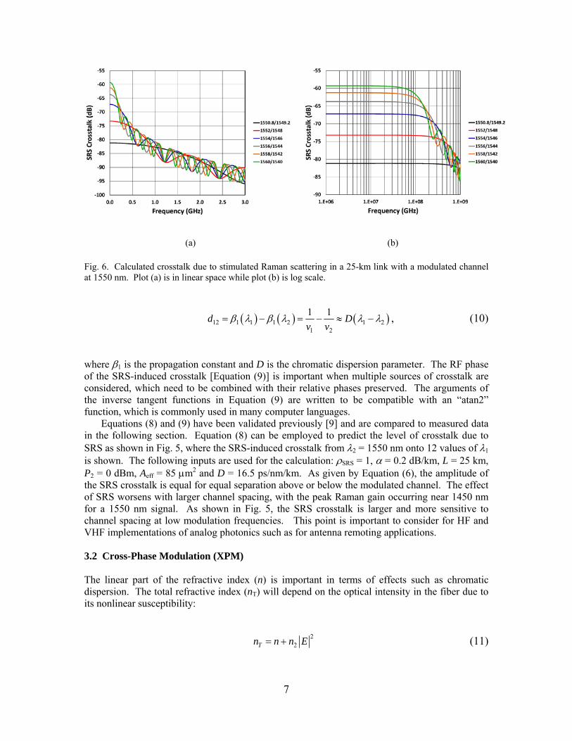
Fig. 6. Calculated crosstalk due to stimulated Raman scattering in a 25-km link with a modulated channel at 1550 nm. Plot (a) is in linear space while plot (b) is log scale.
( ) ( ) (12 1 1 1 2 1 21 2
dv v
)1 1 Dβ λ β λ λ λ= − = − ≈ − , (10)
where β1 is the propagation constant and D is the chromatic dispersion parameter. The RF phase of the SRS-induced crosstalk [Equation (9)] is important when multiple sources of crosstalk are considered, which need to be combined with their relative phases preserved. The arguments of the inverse tangent functions in Equation (9) are written to be compatible with an “atan2” function, which is commonly used in many computer languages.
Equations (8) and (9) have been validated previously [9] and are compared to measured data in the following section. Equation (8) can be employed to predict the level of crosstalk due to SRS as shown in Fig. 5, where the SRS-induced crosstalk from λ2 = 1550 nm onto 12 values of λ1 is shown. The following inputs are used for the calculation: ρSRS = 1, α = 0.2 dB/km, L = 25 km, P2 = 0 dBm, Aeff = 85 μm2 and D = 16.5 ps/nm/km. As given by Equation (6), the amplitude of the SRS crosstalk is equal for equal separation above or below the modulated channel. The effect of SRS worsens with larger channel spacing, with the peak Raman gain occurring near 1450 nm for a 1550 nm signal. As shown in Fig. 5, the SRS crosstalk is larger and more sensitive to channel spacing at low modulation frequencies. This point is important to consider for HF and VHF implementations of analog photonics such as for antenna remoting applications. 3.2 Cross-Phase Modulation (XPM) The linear part of the refractive index (n) is important in terms of effects such as chromatic dispersion. The total refractive index (nT) will depend on the optical intensity in the fiber due to its nonlinear susceptibility:
22Tn n n E= + (11)
7
where
( )32
3 Re8
n n χ⎡ ⎤= ⋅ ⎣ ⎦ (12)
is the nonlinear index coefficient and E is the electric field in the fiber [4]. A typical value of n2 for single-mode fiber is n2 = 2.6×10⁻²⁰ m2/W [11] but precise values depend on the specific fiber type. If the intensity is modulated, the index of refraction will be modulated, which will cause phase modulation of a signal propagating in the fiber. This process gives rise to self-phase modulation (SPM) and cross-phase modulation (XPM).
The nonlinear refraction can convert intensity modulation to phase modulation in the fiber. A single signal can impose such modulation onto itself, the SPM process. Phase modulation can be imposed onto a signal by other signals in the fiber, the XPM effect. An analysis of Equation (11) can show that the phase shift imposed by XPM is twice that due SPM for two equal-intensity optical signals. For an intensity-modulation direct-detection link, the nonlinear phase modulation by itself may not be a problem because a photodiode alone is insensitive to optical phase fluctuations. However, SPM and XPM can be converted to intensity modulation by chromatic dispersion. Likewise, a constant intensity modulation, such as phase modulation, will not cause SPM or XPM. However, if chromatic dispersion converts the phase modulation to intensity modulation, the intensity modulation can cause SPM and XPM, which can then distortion the original phase-modulated signal. The effects of SPM and XPM are therefore strongly dependent on the dispersion map for a link, not simply the net dispersion. Therefore, the crosstalk mechanism for the phase-modulated link is a three step process. First, dispersion transforms the phase-modulation into intensity modulation. This intensity modulation then causes XPM, which is converted to intensity-modulated crosstalk via dispersion or the phase-sensitive receiver. This is more efficient with a higher-dispersion fiber first for most of the frequency range shown.
The calculation of XPM-induced crosstalk in a two-channel link involves many of the same parameters used in the previous section to describe SRS crosstalk. For two wavelengths λ1
(unmodulated CW) and λ2 (intensity modulated), the crosstalk can be derived using a technique called the wave-envelope perturbation analysis [12]. The results in terms of the amplitude (XtalkXPM) and RF phase (ΘXPM) of the crosstalk due to XPM are [9]
( ) ( ) ( ) ( )( )
22 1 2 XPM
XPMeff
2 2 2 2 212 12 12 12
22 2 212
2Xtalk
1 2 1 cos 2 sinL L L
n DPA c
e e L d L L d e d L d L
d
α α α
λ ρ
α α α
α
− − −
⎛ ⎞Ω= ×⎜ ⎟
⎝ ⎠⎡ ⎤+ − − Ω − + Ω Ω + + Ω⎣ ⎦
+ Ω
(13)
( )( )
12 121 112 sin2tan tanLe d L d Ld
L
αα −− −
XPM 2 2 212 12cos 1Ld e d Lαα α−
⎡ ⎤⎛ ⎞ Ω − ΩΩΘ = + ⎢ ⎥⎜ ⎟
− Ω Ω − +⎢ ⎥⎝ ⎠ ⎣ ⎦ (14)
8
(a)
(b)
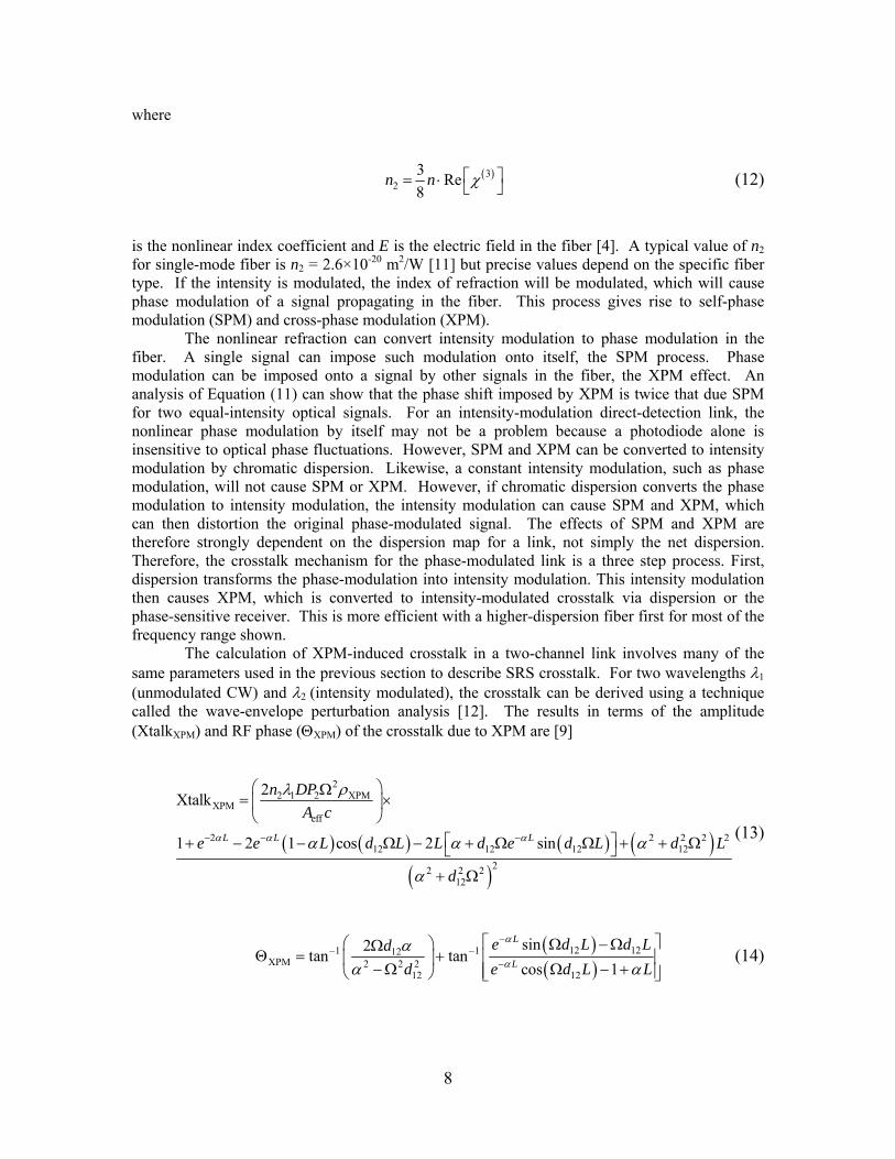
Fig. 7. Calculated crosstalk due to XPM in a 25-km link with a modulated channel at 1550 nm. Plot (a) is in linear space while plot (b) is log scale. where all parameters are as defined previously and ρXPM is the polarization overlap factor for the XPM process. Neglecting the effects of PMD, ρXPM ranges from one-third for perpendicular polarizations to one for parallel polarizations. Like the SRS case, the crosstalk due to XPM is symmetric about the modulation channel for the wavelengths shown. At low modulation frequencies, the crosstalk is very low as governed by the first term in Equation (13). However, the crosstalk due to XPM increases rapidly with frequency as shown in Fig. 7. The effect of channel spacing for XPM is opposite that for SRS; the efficiency of XPM-induced crosstalk is higher at narrower channel spacing. The theory for XPM as given by Equation (13) is quite useful in predicting a variety of scenarios but can sometimes yield erroneous results as described by [13]. Particularly, the effects of pump channel distortion, which are not included in Equation (13), are important at high modulation frequency and/or some dispersion-managed fiber spans [13].
9
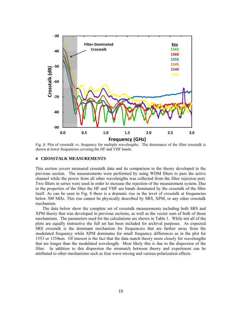
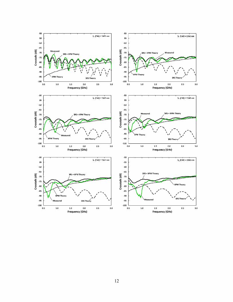
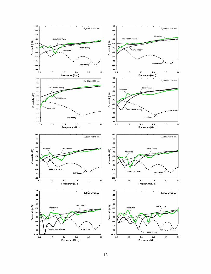
Fig. 8: Plot of crosstalk vs. frequency for multiple wavelengths. The dominance of the filter crosstalk is shown at lower frequencies covering the HF and VHF bands. 4 CROSSTALK MEASUREMENTS This section covers measured crosstalk data and its comparison to the theory developed in the previous section. The measurements were performed by using WDM filters to pass the active channel while the power from all other wavelengths was collected from the filter rejection port. Two filters in series were used in order to increase the rejection of the measurement system. Due to the properties of the filter the HF and VHF are bands dominated by the crosstalk of the filter itself. As can be seen in Fig. 8 there is a dramatic rise in the level of crosstalk at frequencies below 300 MHz. This rise cannot be physically described by SRS, XPM, or any other crosstalk mechanism. The data below show the complete set of crosstalk measurements including both SRS and XPM theory that was developed in previous sections, as well as the vector sum of both of those mechanisms. The parameters used for the calculations are shown in Table 1. While not all of the plots are equally instructive the full set has been included for archival purposes. As expected SRS crosstalk is the dominant mechanism for frequencies that are farther away from the modulated frequency while XPM dominates for small frequency differences as in the plot for 1553 or 1554nm. Of interest is the fact that the data match theory more closely for wavelengths that are longer than the modulated wavelength. Most likely this is due to the dispersion of the filter. In addition to this dispersion the mismatch between theory and experiment can be attributed to other mechanisms such as four wave mixing and various polarization effects.
10
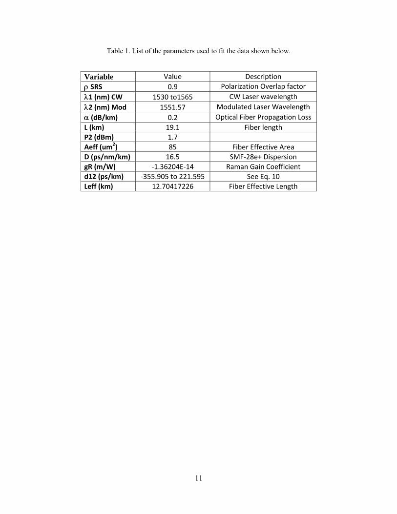
Table 1. List of the parameters used to fit the data shown below.
Variable Value Description ρ SRS 0.9 Polarization Overlap factor λ1 (nm) CW 1530 to1565 CW Laser wavelength λ2 (nm) Mod 1551.57 Modulated Laser Wavelength α (dB/km) 0.2 Optical Fiber Propagation Loss L (km) 19.1 Fiber length P2 (dBm) 1.7 Aeff (um2) 85 Fiber Effective Area D (ps/nm/km) 16.5 SMF‐28e+ Dispersion gR (m/W) ‐1.36204E‐14 Raman Gain Coefficient d12 (ps/km) ‐355.905 to 221.595 See Eq. 10 Leff (km) 12.70417226 Fiber Effective Length
11
12
13

14
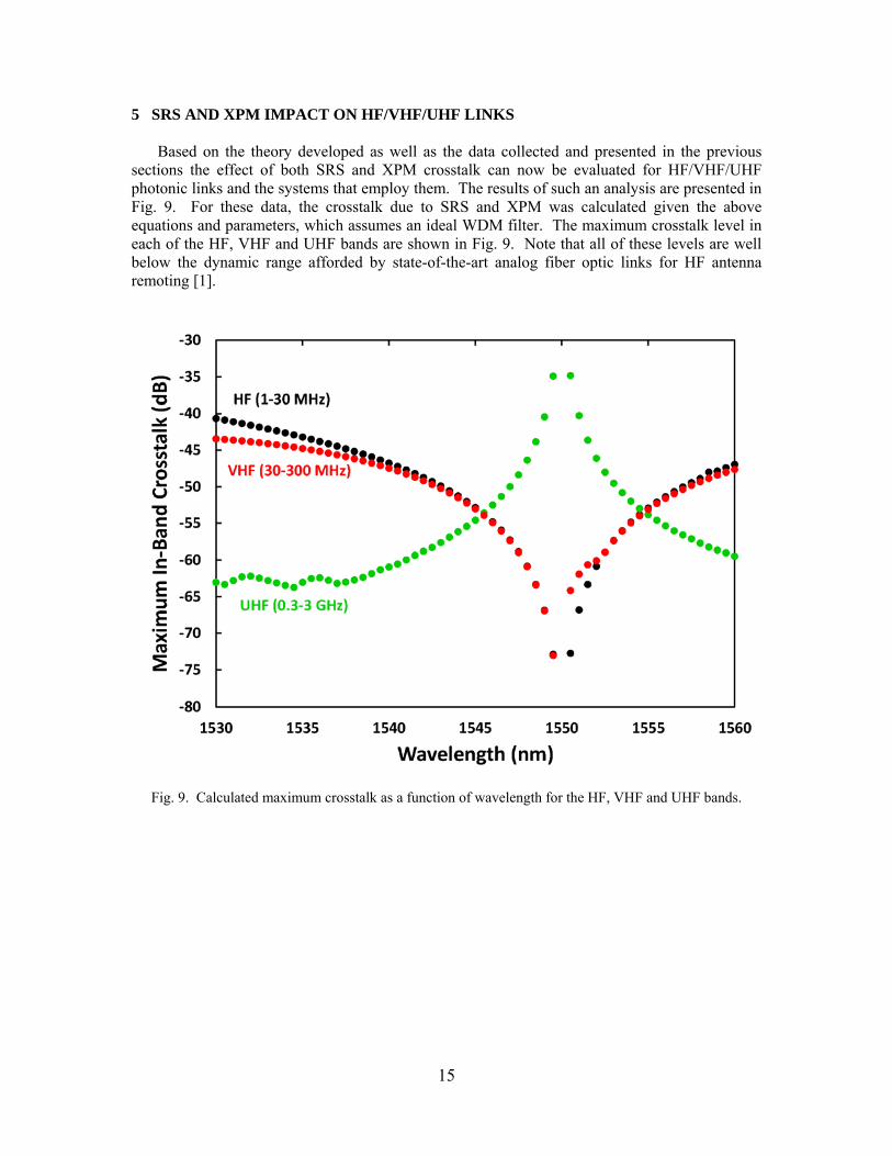
5 SRS AND XPM IMPACT ON HF/VHF/UHF LINKS Based on the theory developed as well as the data collected and presented in the previous sections the effect of both SRS and XPM crosstalk can now be evaluated for HF/VHF/UHF photonic links and the systems that employ them. The results of such an analysis are presented in Fig. 9. For these data, the crosstalk due to SRS and XPM was calculated given the above equations and parameters, which assumes an ideal WDM filter. The maximum crosstalk level in each of the HF, VHF and UHF bands are shown in Fig. 9. Note that all of these levels are well below the dynamic range afforded by state-of-the-art analog fiber optic links for HF antenna remoting [1].
Fig. 9. Calculated maximum crosstalk as a function of wavelength for the HF, VHF and UHF bands.
15

6 CONCLUSIONS AND FURTHER CONSIDERATIONS This report has examined the theoretical expectations and experimental results of crosstalk due to Stimulated Raman Scattering and Cross Phase Modulation in HF/VHF/UHF photonic links. Using the equations for SRS and XPM the best case was calculated for each of the three bands under the constraint of a two wavelength system. Given the results presented in this report maintaining the dynamic range of the photonic links will be quite difficult. This will prove especially true for the HF/VHF bands where it would be desirable to avoid the filter dominated crosstalk shown here. If a WDM system is to be deployed in the future careful and thorough analysis and testing of the filters considered for deployment should be undergone before a final system architecture is selected. In addition to an analysis of filter crosstalk there are several other processes that could be considered for research in order to more full characterize and gain a better understanding of the complicated interactions in long fiber lengths within the bands of interest. Among these are XPM being converted to intensity modulation due to the dispersion of the WDM filter and an in depth examination of the effects of four wave mixing which was briefly discussed in this report. Also to be considered are the effects of multiple wavelengths interacting with each other. In addition to crosstalk effects there are a number of optical processes that can result in RF distortions. These include, FWM, polarization mode dispersion, and chromatic dispersion. The later of these can be easily corrected by using dispersion compensating fiber however the use of this fiber can have a deleterious effect on crosstalk. Also for long haul links that employ optical amplifiers the RF distortion due to these amplifiers must be considered as well.
16
17
REFERENCES [1] Urick, V. J., Diehl, J., Hastings, A., Sunderman, C., McKinney, J. D., Devgan, P. S., Dexter,
J. L., and Williams, K. J., “Analysis of fiber-optic links for HF antenna remoting,” NRL Memorandum Report, NRL/MR/5650-08-9101 (2008).
[2] Urick, V. J., Hastings, A., Sunderman, C., Diehl, J., Colladay, K., Dexter, J. L., Williams, K. J., “Field test on the feasibility of remoting HF antenna with fiber optics,” NRL Memorandum Report, NRL/MR/5652-08-9137 (2008).
[3] Urick, V. J., Colladay, K. R., Sunderman, C. E., Diehl, J. F., Devgan, P. S., and Williams, K. J., “Extended-distance analog fiber-optic links for HF antenna remoting,” internal NRL Report (2009).
[4] Agrawal, G., Nonlinear Fiber Optics, 5th edition, Academic Press (2013). [5] Campillo, A. L. and Bucholtz, F., “Increased nonlinear crosstalk in analog wavelength-
division-multiplexed links due to the chromatic dispersion of optical filters,” IEEE Photonics Technology Lett., 18(19), 2014-2016 (2006).
[6] Wan, P. and Conradi, J., “Impact of double Rayleigh backscatter noise on digital and analog fiber systems,” J. of Lightwave Technol., 14(3), 288-297 (1996).
[7] Smith, R. G., “Optical power handling capacity of low loss optical fibers as determined by stimulated Raman and Brillouin scattering,” Applied Optics, 11(11), 2489-2494 (1972).
[8] Stolen, R. H. and Ippen, E. P., “Raman gain in glass optical waveguides,” Applied Physics Lett., 22(6), 276-278 (1973).
[9] Phillips, M. R. and Ott, D. M., “Crosstalk due to optical fiber nonlinearities in WDM CATV lightwave systems,” J. of Lightwave Technology, 17(10), 1782-1792 (1999).
[10] Campillo, A. L., Funk, E. E., Tulchinsky, D. A., Dexter, J. L., and Williams, K. J., “Phase performance of an eight-channel wavelength-division-multiplexed analog-delay line,” J. of Lightwave Technology, 22(2), 440-447 (2004).
[11] Antona, J. C., Bigo, S., and Kosmalski, S., “Nonlinear index measurements of various fibre types over C+L bands using four-wave mixing,” in Proc. 27th European Conf. on Optical Communications, 270-271 (2001).
[12] Phillips, M. R., Darcie, T. E., Marcuse, D., Bodeep, G. E., and Frigo, N. J., “Nonlinear distortion generated by dispersive transmission of chirped intensity-modulated signals,” IEEE Photonics Technology Lett., 3, 481-483 (1991).
[13] Marks, B. S., Menyuk, C. R., Campillo, A. L., and Bucholtz, F., “Analysis of interchannel crosstalk in a dispersion-managed analog transmission link,” J. of Lightwave Technology, 24(6), 2305-2310 (2006).


![DESIGN AND CHARACTERIZATION OF LONG-HAUL SINGLE … · Fiber-optic links have been shown to offer increased performance in these applications [3]. Whether these links use either intensity](https://static.fdocuments.net/doc/165x107/5fbaebce2683392bdc25370a/design-and-characterization-of-long-haul-single-fiber-optic-links-have-been-shown.jpg)