Fiber General Catalog -...
28
Fiber General Catalog Meeting the diverse needs of our customers with a wide range of different models and an improved product line-up. http://www.fiber-sensor.com INDEX
Transcript of Fiber General Catalog -...

Fiber General Catalog
Meeting the diverse needs of our customers with a wide range of different models and an improved product line-up.
http://www.fiber-sensor.com
INDEX

1
Detecting chip components as they are drop-sorted / FT-WA8Has a wide 11 mm 0.433 in detection area. Vibrating objects and minute objects passing at high speed, that were previously difficult to detect, can now be easily detected using FT-WA8 in combination with the FX-300 series amplifiers.
Detecting components from a parts feeder / FT-WZ8EThe industry’s smallest ultra-thin rectangular fiber head, with dimensions of W3 H12 D8 mm W0.018 H0.472 D0.315 in. Contains a sharp bending fiber cable attachment area, thus saving installation space.
New sharp bending fiber applications
"3 15 mm"0.118 0.591 in
570 mm22.441 in
570 mm22.441 in
M4 15 mm 0.591 in
570 mm22.441 in
"2.5 8 mm"0.098 0.315 in
* The sensing ranges indicated above were obtained using LONG mode.
Now Available – Our Long-awaited, Improved Selection of Sharp Bending FibersAdditional new products bring our fiber line-up to a total of 24 models, consisting of 13 models of thru-beam fibers and 11 models of reflective fibers.
* Sleeve part cannot be bent.
Product line-up consists of 13 modelsof sharp bending thru-beam fibers
Coming soon
160 mm6.299 in
M3 15 mm 0.591 in
160 mm6.299 in
"1.5 8 mm"0.059 0.315 in
1,200 mm47.244 in
"3 8 mm"0.118 0.315 in
700 mm27.559 in
W8.5 H12 D3 mmW0.355 H0.472 D0.118 in
1,500 mm59.055 in
W3 H12 D8 mmW0.118 H0.472 D0.315 in
2,500 mm 59.055 in
W3 H8 D12 mmW0.118 H0.315 D0.472 in
3,600 mm141.732 in
90 mm3.543 in
W4.2 H31 D13.5 mmW0.165 H1.22 D0.531 in
3,600 mm141.732 in
W5 H69 D20 mmW0.197 H2.717 D0.787 in
1,700 mm66.929 in
"4 25 mm"0.157 0.984 in
"1 15 mm"0.039 0.591 in
"2 15 mm"0.079 0.591 in
FT-WS3Standard
FT-W8Standard
FT-WS8Standard
FT-W4Small diameter
Lens mountable
FT-WS8LWith lens
FT-WS4Small diameter
FT-WZ8Rectangular head . Front sensing
FT-WZ8ERectangular head . Side sensing
FT-WZ8HRectangular head . Top sensing
FT-WA30Wide beam (32 mm 1.26 in)
FT-WA8Wide beam(11 mm 0.433 in)
FT-WV42Side-view
FT-WKV8Narrow beamSide-view
Digital fiber sensorFX-301
Now it’s possible to simultaneously cut two fibers to the same lengthEach fiber (with some exceptions) has a newly developed two-in-one fiber attachment (FX-AT3/AT4/AT5/AT6) which enables two fibers to be cut simultaneously to the same length with the new fiber cutter (FX-CT2). Also, since the fibers can be attached to the amplifier while being fixed in position in the two-in-one fiber attachment, sensitivity changes resulting from variation in the amount of fiber insertion do not occur.
on’t break, to
Fiber attachment integrates 2 individual fibers into a single unit (Accessories for fibers)
Stable sensing is obtained, as 2 fibers are fixed securely together for usage.
FX-AT2(for fixed-length fiber)
FX-AT3(for "2.2 mm "0.087 in fiber)
FX-AT4(for "1 mm "0.039 in fiber)
FX-AT5(for "1.3 mm "0.051 in fiber)
FX-AT6(for "1 mm "0.039 in and "1.3 mm "0.051 in mixed fiber)
Newlydeveloped

2
Detecting water taken out from a FOUP / FD-WL42Due to the distance-limiting properties, detection is unaffected by colors or surface luster, therefore, the upper wafer will not be accidentally detected. Furthermore, FD-WL42 is the smallest unit in the industry, with a thickness of only 3 mm 0.118 in.
Detecting the presence of a glass substrate within a cassette / FD-WL41By utilizing its excellent distance-limiting properties, reliable detection of the specific glass substrate located only in the desired position within the cassette, can be guaranteed.
WaferFOUP
Glass substrate cassette
Glass substrate
*The sensing ranges indicated above were obtained using LONG mode.
FD-WL41Fixed-focus reflective . Glass substrate detection
FD-WL42Fixed-focus reflective . Specular object detection
FD-WG4High precisionCoaxial
FD-WSG4High precisionCoaxial
FD-WKZ1 Long range . Rectangular head
FD-WV42Side-view
FD-WS8Small fiber head
FD-WT4Small fiber head . Small diameter
FD-WT8Small fiber head
30 mm 1.181 in
FD-W44Small diameter . With sleeve
Lens mountable
4 mm0.157 in
3 mm0.118 in
FD-W8Standard
Product line-up consists of 11 modelsof sharp bending reflective fibers
Coming soon
190 mm7.48 in
M6 15 mm 0.591 in
M4 12 mm 0.472 in"1.48 40 mm"0.058 1.575 in
190 mm7.48 in
M4 12 mm 0.472 in
190 mm7.48 in
"3 15 mm"0.118 0.591 in
30 mm1.181 in
M3 12 mm 0.472 in
24 21 mm0.945 0.827 in
6.5 to 14 mm0.256 to 0.551 in(Convergent point : 8 mm 0.315 in)
15 19 mm0.591 0.748 in
0.6 to 3.5 mm0.024 to 0.138 in(Convergent point : 2 mm 0.079 in)
65 mm2.559 in
M4 25 mm 0.984 in
65 mm2.559 in
20 to 480 mm0.787 to 18.898 in
"3 15 mm"0.118 0.591 in
W5.2 H9.5 D15 mmW0.205 H0.374 D0.591 in
* Sleeve part cannot be bent.
15 mm0.591 in
"2 15 mm"0.079 0.591 in
"3 15 mm"0.118 0.591 in
Aperture angle of 2° or less
Narrow beam . Side-viewFT-WKV8
The fiber can be bent sharply, like an electric wire, to avoid space wastage in installation because of its small allowable bending radius of R1 mm R0.039 in or more (FD-WG4,FD-WSG4 : R2 mm R0.079 in or more).
Allowable bending radiusR1 mm R0.039 in or more
Allowable bending radiusR25 mm R0.984 in or more
on’t break, to
Can be rotated freely in any direction R1 mm R0.039 in or more
Sharp bending fiber Conventional fiber
Fiber cable won’t break, even when bent to this extent!

3
Tough Flexible Fiber / FT-P81X,FD-P81X,FD-G6XStainless steel braiding protects the fiber cable and prevents fiber breakage due to snagging. The allowable bending radius is R10 mm R0.394 in or greater. The fiber will bend flexibly, without breaking. The installation of troublesome protection tubes for breakage prevention is no longer required.
Flexible Fiber / FT-P60,FT-PS1These fibers are most suitable for usage on moving components due to their high resistance to repeated flexing. Our product line now includes the new FT-P60 (M4 type, with lens attachment mountable) and FT-PS1 (ultra-small diameter type, with "1 mm "0.039 in). An allowable bending radius of R4 mm R0.157 in or greater has been achieved and the fiber can withstand repeated bending for more than 1 million times (at R10 mm R0.394 in).
FT-P81XLens mountable
*The sensing ranges indicated above were obtained using LONG mode.
*The sensing ranges indicated above were obtained using LONG mode.
Tough flexible fiber line-up
Flexible fiber line-up
FT-P60
FT-PS1
FD-P81X
FD-G6X
FD-P50
Lens mountable
Lens mountable
FD-P60
M420 mm 0.787 in
650 mm25.591 in
185 mm7.283 in
M619 mm 0.748 in
90 mm3.543 in
M318 mm 0.709 in
M415 mm 0.591 in
400 mm15.748 in
80 mm3.15 in
90 mm3.543 in
"16 mm "0.0390.236 in
"315 mm"0.1180.591 in
90 mm3.543 in
M415 mm 0.591 in
Strong stainless steel meshprotects fiber cables from breakage
Tough, but bends flexibly!Allowable bending radiusR10 mm R0.394 in or greater
Conventional Fiber
Tough Flexible Fiber
No cable breakage
Conventional Fiber
Flexible Fiber
Bending durability 1 million times or more!Allowable bending radius R4 mm R0.157 in or more
No cable breakage
Cable breakage
by repeated bending
Cable breakage by repeated bending

Suction detection for chipsThis fiber unit can be used to confirm chip presence, when mounting chips using a flip chip bonder.
Counting connector pinsThe optimum combination of lens and fiber can be selected, in accordance with the connector pin size and pin pitch.
4
* The spot diameter can be changed by adjusting the length of fiber inserted.
"0.7 to "2.0 mm"0.028 to "0.079 in
18.5 to 43 mm approx.0.728 to 1.693 in approx.
* The spot diameter can be changed by adjusting the length of fiber inserted.
"0.5 to "3.0 mm"0.02 to "0.12 in
13 to 30 mm approx.0.512 to 1.181 in approx. W6.3H20.3D10.3 mm
W0.248H0.799D0.403 in
"0.5 mm"0.02 in
"0.2 mm"0.008 in
"0.15 mm"0.006 in
"0.1 mm"0.004 in
"0.3 mm"0.012 in
Finest Spot Lens / FX-MR6High Precision Fiber / FD-EG2,FD-EG3An ultra-small "0.1 mm "0.004 in spot size has now been made possible through the integration of our finest spot lens (FX-MR6) with our precision fiber (FD-EG3).
70.5 mm0.2760.02 in
"516 mm"0.1970.63 in
29.5 mm1.161 in
70.5 mm0.2760.02 in
70.5 mm0.2760.02 in
70.5 mm0.2760.02 in
70.5 mm0.2760.02 in
"516 mm"0.1970.63 in
"516 mm"0.1970.63 in
29.5 mm1.161 in
29.5 mm1.161 in
28.5 mm1.122 in
"4.515 mm"0.17710.177 in
"4.515 mm"0.17710.177 in
36.5 mm1.122 in
"827.1 mm"0.3151.067 in
15 mm0.591 in
M317 mm 0.669 in
25 mm0.984 in
M317 mm 0.669 in
Small spot applications
*The sensing ranges indicated above were obtained using LONG mode.
FX-MR2FD-WG4/G4
FX-MR5FD-WG4/G4
FD-EG3 (Fiber)Coaxial
FD-EG2 (Fiber)Coaxial
FX-MR3FD-EG1
FX-MR3FD-G4/WG4
FX-MR6FD-EG1
FX-MR6FD-EG2
FX-MR6FD-EG3
Spot lens & high precision fiber line-up
FX-MR6 (lens)FD-EG3 (fiber)Spot size"0.1 mm"0.004 in
Distance to focal point 70.5 mm 0.2760.02 in
Now available - ultra-smallspot size of "0.1 mm "0.004 in(FX-MR6FD-EG3)
This precisely focused spot is produced through the use of a new lens design, allowing stable sensing to be achieved, even for minute sensing tasks, such as the detection of ultra-small chip components (0603 chips, etc.).
by repeated bending

Liquid sensing
5
Reliable detectionThe unique effect of capillarity enables reliable detection of small leaks and viscous liquids.
Compact, space-savingThis slim (10 mm 0.394 in) side-mounting fiber is especially good for use in confined spaces.
Ideal for chemicals and volatile materialsThis fiber type sensor is safer to use with volatile materials (SEMI S2 compliant). The fluorine resin fiber head makes it ideal for use with chemicals.
Note: Dedicated amplifier FX-301-F must be used with the FD-F7 series.
Note: Dedicated amplifier FX-301-F must be used with the FT-F9 series.
A new slim fiber ideal for sensing chemical leaks
Leak Detection Fiber / FD-F7 SERIES
Safer fiber type sensorIn response to the demand for higher safety standards throughout the world, including SEMI S2, safer sensing can be achieved by placing the amplifier for this fiber sensor away from dangerous locations, such as locations with volatile chemicals, where electrical circuits increase the risk of fire or explosion.
Reliable detection not affected by bubbles or dropletsLatest optical fiber techniques have solved problems caused by bubbles, droplets or liquid leakage that arise in conventional pipe-mountable sensors.
Reliably detect liquid in pipe
Heat-resistant Fixed-focus Reflective Fiber / FD-H18-L31,FD-H30-L32 SERIES
Glass substrate detection in high temperature production line
High precision detectionIn addition to excellent heat resistance, these fibers have achieved a repeatability of 0.06 mm 0.002 in for transparent glass substrates.
Extended detection rangeNow available with full-range detection capabilities containing no dead zones (in both LONG and STD modes). As well, an extended detection distance of 15 mm 0.591 in (in LONG mode) has been achieved, even allowing for the detection of warping in glass substrates.
Thin fiber headIn addition to having heat resistance of 180C 356F and 300C 572F, respectively, these new fiber heads are thin - now only 5 mm 0.197 in thick. Even more space can now be saved during installation.
Liquid Fiber / FT-F9 SERIES
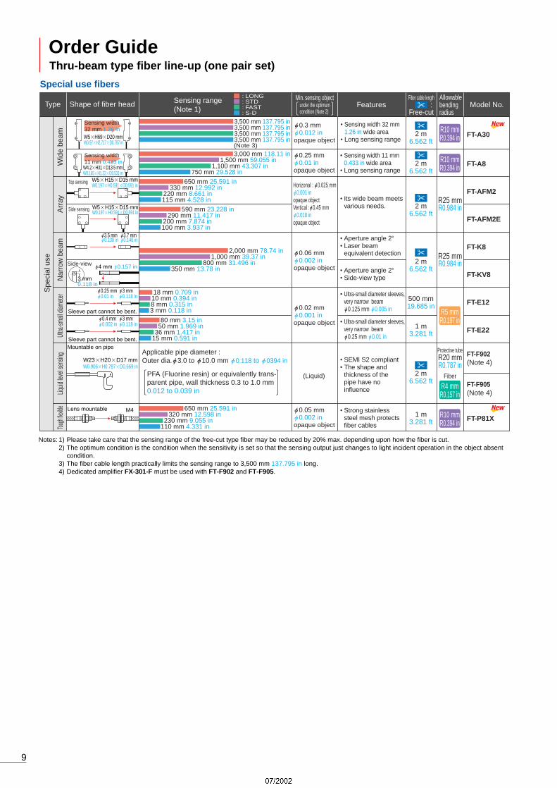
Wide Beam Fiber / FT-WA30/A3032 mm 1.26 in New wide-area fiber launched!
Seal slit is avalableThe using of a seal slit reduces the amount of emitting beam and allows sensing of much smaller objects.
FT-WA30/A30 fiber heads are not susceptible to interference from peripheral objectsAs these fibers incorporate light sources having almost the same collimated beam as lasers, beam interference from peripheral objects is minimal, thus permitting stable detection to be performed in crowded areas.
A bending radius of R1 mm (R0.039 in) has been made possibleThe allowable bending radius for FT-WA30 is R1 mm R0.039 in or greater. These fibers can be bent as much as if they were electric wires, thus saving tremendous amounts of space during fiber installation.
Space-saving installation is now possibleFT-WA30/A30 has a depth of 20 mm 0.787 in allowing for installation on the narrowest production lines.
Leak detection for use in semiconductor device manufacturing
Glass substrate detection in high temperature production line
Detecting dropping objects
• Capillarity effect
Leakage pan
Liquid
Fiber head
10 mm0.394 in
FT-F9
FD-F7
Liquid present Liquid absent
Beam-receiving signalLow
Beam-receiving signalHigh
Glass substrateGlass substrate

Detecting wafer cassette in cleaning tank
Chemical-resistant Rectangular Head Fiber / FT-Z8Y SERIES
High accuracy sensingEven with variation among glass subst- rates, the positioning error is 0.2 mm 0.008 in or less (at sensing range 5 to 17 mm 0.197 to 0.669 in).
Single type serving two applicationsAs the fiber can sense an object located even at 0 mm, it can be used for sensing, as well as alignment checking of the glass substrate (at sensing range 5 to 17 mm 0.197 to 0.669 in).
Long-range sensing capabilityThe sensing range is as long as 0 to 20 mm 0.787 in. In addition, the fiber will not detect a glass substrate 30 mm 1.181 in or more away achieving outstanding detecting characteristics for limited distance.
Compact design allows easy, flexible positioningCompact size of W17H29D3.8 mm W0.669H1.142D0.15 in. The outer diameter of the fiber cable is "1.3 mm "0.118 in, enabling the fiber to be routed with R4 mm R0.157 in bending radius.
High accuracy & stable sensing
Usable with various chemical liquidsWith the case made of PFA and fiber sheath with PFA, the fiber can be used with various types of chemical liquids.
Easy cutting of even PFA protected fiberAs the diameter of the fiber cable, including the PFA protected portion, is only "2.2 mm "0.087 in, you can simply cut the fiber cable to a desired length.
Square-shaped head provides easy mountingThe square-shaped head offers both easy installation and easy light-beam alignment. The head measures W7H15D13 mm W0.276H0.591D0.512 in, and can be mounted with M3 screws at two locations.
Thru-beam type side-view with 3,500 mm 137.795 in long sensing range
Excellent explosion-proof structure complying with SEMI S2Since the fiber does not have any electrical circuit in the sensing part, it offers an excellent explosion-proof structure.
Chemical-resistant square-shaped head with no light-beam misalignment
Flexible Heat-resistant Fiber / FT-H20W SERIES
Rectangular Head Fiber / FT-Z8 SERIES
Heat-resistant temperature 200C (392F)Withstands temperature up to 200C 392F. Sensing is now possible in high temperature environments, such as detecting the presence of ICs in a high temperature handler.
Fiber cable types of 1 m (3.281 ft) and 2 m (6.562 ft) lengths are available
Bending radius R10 mm (R0.394 in) for space savingBy utilizing a PTFE exterior coating, bends of R10 mm R0.394 in are possible, even in high temperature environments. Cabling can be laid out freely, thus saving space.
A bending radius of R10 mm R0.394 in is possible even in high temperature environments
Extremely thin, the smallest size in the industryThe smallest super thin type rectangular head fiber in the industry with dimensions of W3H12D8 mm W0.118H0.472D0.315 in (side sensing type).
Rectangular fiber head allows for easy installationIt can be installed with only two M2 screws, allowing easy light beam axis alignment.
Utilizes flexible inflection resistant cableMinimum permissible bending radius of R4 mm R0.157 in. The fiber can withstand repeated bending 1 million times or more (at R10 mm R0.394 in).
Long sensing range 2,700 mm (106.279 in)
Smallest in the industryEasy, space-saving screw type installation
Glass Substrate Alignment & Seating Confirmation Fiber / FD-L43
Glass substrate alignment & seating confirmation
Detection of components from a parts feeder
IC detection within a high temperature handler
6
Conventional model The FT-H20W series
Enclosure: PFA
Fiber sheath: PFA
FD-L43
FT-Z802Y
Cleaning tank
Wafer casstte
Sensing object (glass substrate)
Fiber headSenses up to 20 mm 0.787 infrom seating position.
Does not sense when the distance is 30 mm 1.181 inor more.
Fiber head
0 to 20 mm 0.787 in30 mm 1.181 in or more
Glass substrate
Glass substrate

7
FT-FM10L
FT-SFM2L
FT-B8
FT-NB8
FT-FM2
FT-FM2S
FT-FM2S4
FT-T80
FT-SFM2
FT-N8
FT-NFM2
FT-NFM2S
FT-NFM2S4
FT-SNFM2
FT-R80
FT-SFM2SV2
FT-V22
FT-V41
R25 mmR0.984 in
R25 mmR0.984 in
R25 mmR0.984 in
R25 mmR0.984 in
R25 mmR0.984 in
R25 mmR0.984 in
R25 mmR0.984 in
R25 mmR0.984 in
10 m32.808 ft
2 m6.562 ft
2 m6.562 ft
2 m 6.562 ft(Note 3)
2 m6.562 ft
2 m 6.562 ft(Note 3)
2 m6.562 ft
2 m6.562 ft
2 m6.562 ft
1 m6.562 ft
2 m6.562 ft
• Large lenses on the fiber heads increase the sensing range significantly.
• Long sensing range with small fiber heads of "2.5 mm "0.098 in
• Long sensing range
• Long sensing range with miniature fiber heads
• Low price
• Low price
• The fiber head is bent at a right angle with 5 mm 0.197 in bending radius at the neck.
• The side-view sensing
• Space-saving
• Suitable for detection in a congested equipment
• Free-cut type
• Free-cut type
"0.4 mm"0.016 inopaque object
"0.02 mm"0.001 inopaque object
"0.04 mm"0.002 inopaque object
"0.03 mm"0.001 inopaque object
"0.03 mm"0.001 inopaque object
"0.03 mm"0.001 inopaque object
"0.025 mm"0.001 inopaque object
"0.04 mm"0.002 inopaque object
"0.02 mm"0.001 inopaque object
With lens
With lens
Lens mountable
Lens mountable
Sleeve 90 mm 3.543 in
Sleeve 40mm 1.575in
Lens mountable
Sleeve 90 mm 3.543 in
Sleeve 40 mm 1.575 in
Lens mountable
Sta
ndar
dLo
ng s
ensi
ng r
ange
Elb
owS
ide-
view
Notes: 1) Please take care that the sensing range of the free-cut type fiber may be reduced by 20% max. depending upon how the fiber is cut.2) The optimum condition is the condition when the sensitivity is set so that the sensing output just changes to light incident operation in the object absent
condition.3) Fiber cutter is not supplied as accessory along with FT-NB8 and FT-N8. Please order it separately.
19,500 mm 767.715 in14,000 mm 551.18 in
10,000 mm 393.7 in3,800 mm 149.606 in
1,600 mm 62.992 in800 mm 31.496 in
580 mm 22.835 in280 mm 11.024 in
1,100 mm 43.307 in530 mm 20.866 in
400 mm 15.748 in180 mm 7.087 in
1,000 mm 39.37 in480 mm 18.898 in
360 mm 14.173 in168 mm 6.614 in
780 mm 30.709 in400 mm 15.748 in
280 mm 11.024 in130 mm 5.118 in
700 mm 27.559 in360 mm 14.173 in
250 mm 9.843 in126 mm 4.961 in
270 mm 10.63 in140 mm 5.512 in
100 mm 3.937 in49 mm 1.929 in
530 mm 20.866 in230 mm 9.055 in
150 mm 9.906 in80 mm 3.15 in
400 mm 15.748 in200 mm 7.874 in
140 mm 5.512 in70 mm 2.756 in
390 mm 15.354 in180 mm 7.087 in
125 mm 4.921 in63 mm 2.48 in
175 mm 6.89 in80 mm 3.15 in60 mm 2.362 in
27 mm 1.063 in
M14
"2.5 mm "0.098 in
M4
M4
M4
M4
"1.48 mm"0.058 in
M4
"1.48 mm"0.058 in
M3
"2.5 mm"0.098 in
M4
M3
M3
"0.88 mm "0.035 in
M3
"0.88 mm "0.035 in
"1.5 mm"0.059 in
M4
"2 mm "0.079 in "2.5 mm "0.098 in
0.6 mm 0.024 in
Sleeve part cannot be bent.
"1 mm "0.039 in "2.5 mm "0.098 in
0.6 mm 0.024 in
Sleeve part cannot be bent.
Sleeve part cannot be bent.0.8 mm 0.031 in
"1.5 mm "0.059 in "2.5 mm "0.098 in
Type Features Model No.Shape of fiber head Sensing range (Note 1)
: LONG: STD : FAST: S-D
Min. sensing object Fiber cable length Allowablebendingradius
:Free-cut
FiberR25 mmR0.984 inSleeve
R10 mmR0.394 in
FiberR25 mmR0.984 inSleeve
R10 mmR0.394 in
Thru-beam type fiber line-up (one pair set)
Standard fibers
under the optimumcondition (Note 2)
Order Guide

8
Type Features Model No.Shape of fiber headMin. sensing object Fiber cable length Allowable
bendingradius
:Free-cut
With lens
Lens mountable
Lens mountable
FT-WA30
FT-WA8
FT-WZ8H
FT-WZ8E
FT-WZ8
FT-WKV8
FT-WS8L
FT-W8
FT-WS3
FT-WS8
FT-W4
FT-WS4
FT-Z8H
FT-Z8E
FT-Z8
FT-P80
FT-P60
FT-P40
FT-P2
FT-PS1
2 m6.562 ft
2 m6.562 ft
2 m6.562 ft
2 m6.562 ft
2 m6.562 ft
2 m6.562 ft
2 m6.562 ft
• Sensing width 11 mm 0.433 in wide area
• Long sensing range
• Sensing width 32 mm 1.26 in wide area
• Long sensing range
• Installs with M2screws, allowing easy beam axis alignment
• Allowable bending radius: R1 mm R0.039 in or more
• Long sensing range with fiber heads of "3 mm "0.118 in
• Installs with M2 screws, allowing easy beam axis alignment
• Bending durability:1 million times or more (at R10 mm R0.394 in)
• Bending durability:1 million times or more (at R10 mm R0.394 in)
• Bending durability:1 million times or more (at R10 mm R0.394 in)
• Bending durability:1 million times or more (at R4 mm R0.157 in)
• The side-view sensing
• Aperture angle 2°
"0.25 mm"0.01 inopaque object
"0.3 mm"0.012 inopaque object
"0.08 mm"0.003 inopaque object
"0.05 mm"0.002 inopaque object
"0.04 mm"0.002 inopaque object
"0.06 mm"0.002 inopaque object
"0.02 mm"0.001 inopaque object
"0.03 mm"0.001 inopaque object
"0.05 mm"0.002 inopaque object
"0.03 mm"0.001 inopaque object
"0.02 mm"0.001 inopaque object
"0.03 mm"0.001 inopaque object
"0.04 mm"0.002 inopaque object
"0.02 mm"0.001 inopaque object
Sha
rp b
endi
ngF
lexi
ble
Wid
e be
amR
ecta
ngul
ar h
ead
Narr
ow
beam
Long
sens
ingran
geS
tand
ard
Sm
all d
iam
eter
Rec
tang
ular
hea
dS
tand
ard
Sm
all d
iam
eter
3,500 mm 137.795 in3,500 mm 137.795 in3,500 mm 137.795 in3,500 mm 137.795 in
3,500 mm 137.795 in1,500 mm 59.055 in
1100 mm 43.307 in750 mm 29.528 in
2,500 mm 98.425 in1,200 mm 47.244 in
850 mm 33.465 in410 mm 16.142 in
1,500 mm 59.055 in700 mm 27.559 in
500 mm 19.685 in210 mm 8.268 in
700 mm 27.559 in330 mm 12.992 in
240 mm 9.449 in120 mm 4.724 in
1,700 mm 66.929 in700 mm 27.559 in
600 mm 23.622 in
1,200 mm 47.244 in600 mm 23.622 in
420 mm 16.535 in210 mm 8.268 in
570 mm 22.441 in290 mm 11.417 in
300 mm 11.417 in
200 mm 7.874 in100 mm 3.937 in
100 mm 3.937 in
570 mm 22.441 in290 mm 11.417 in
200 mm 7.874 in
570 mm 22.441 in290 mm 11.417 in
200 mm 7.874 in100 mm 3.937 in
160 mm 6.299 in80 mm 3.15 in
55 mm 2.165 in28 mm 1.102 in
2,700 mm 106.299 in1,400 mm 55.118 in
1,000 mm 39.37 in490 mm 19.291 in
1,600 mm 62.992 in800 mm 31.496 in
600 mm 23.622 in280 mm 11.024 in
800 mm 31.496 in400 mm 15.748 in
300 mm 11.811 in140 mm 5.512 in
650 mm 25.591 in320 mm 12.598 in
230 mm 9.055 in110 mm 4.331 in
400 mm 15.748 in190 mm 7.48 in
140 mm 5.512 in80 mm 3.15 in
250 mm 9.843 in100 mm 3.937 in
75 mm 2.953 in35 mm 1.378 in
280 mm 11.024 in120 mm 4.724 in
90 mm 3.543 in42 mm 1.654 in
80 mm 3.15 in40 mm 1.575 in30 mm 1.181 in
17 mm 0.669 in
2 m6.562 ft
2 m6.562 ft
2 m6.562 ft
1 m3.281 ft
500 mm19.685 in
Notes: 1) Please take care that the sensing range of the free-cut type fiber may be reduced by 20% max. depending upon how the fiber is cut.2) The optimum condition is the condition when the sensitivity is set so that the sensing output just changes to light incident operation in the object absent
condition.3) The fiber cable length practically limits the sensing range to 3,500 mm 137.795 in long. 4) The sheath of FT-P80 is very soft. In the case of insertion in amplifier, please use an attachment (FX-AT3), then insert the fiber in amplifier vertically.
M4
"2.5 mm "0.098 in
"3 mm "0.118 in
"1 mm "0.039 in
M3
"1.5 mm "0.059 in
Lens mountable
(Note 4)
M4
M3
"1.5 mm "0.059 in
Side sensing
Side-view
3 mm0.118 in
Front sensing
Top sensing
R4 mmR0.157 in
R4 mmR0.157 in
R4 mmR0.157 in
R1 mmR0.039 in
R1 mmR0.039 in
R1 mmR0.039 in
R1 mmR0.039 in
R1 mmR0.039 in
R1 mmR0.039 in
R1 mmR0.039 in
Sensing width 32 mm 1.260 in
Sensing width 11 mm 0.433 in
M4
"3 mm "0.118 in
W5H69D20 mmW0.197H2.717D0.787 in
W4.2H31D13.5 mmW0.165H1.22D0.531 in
W3H8D12 mmW0.118H0.315D0.472 in
W3H12D8mmW0.118H0.472D0.315in
W8.5H12D3 mmW0.335H0.472D0.118 in
"4 mm "0.157 in
Side sensing
Front sensing
Top sensing W3H8D12 mmW0.118H0.315D0.472 in
W3H12D8 mmW0.335H0.472D0.118 in
W8.5H12D3 mmW0.335H0.472D0.118 in
Sharp bending fibers / Flexible fibers
Sensing range (Note 1)
: LONG: STD : FAST: S-D
under the optimumcondition (Note 2)
(Note 3)
2 m6.562 ft
FT-A30
FT-A8
FT-AFM2
FT-AFM2E
FT-K8
FT-KV8
FT-E12
FT-E22
FT-F902(Note 4)
FT-F905(Note 4)
FT-P81X
R25 mmR0.984 in
R25 mmR0.984 in
R10 mmR0.394 in
R10 mmR0.394 in
R10 mmR0.394 in
R5 mmR0.197 in
Protective tubeR20 mmR0.787 in
Fiber
2 m6.562 ft
2 m6.562 ft
1 m3.281 ft
2 m6.562 ft
• Sensing width 11 mm 0.433 in wide area
• Long sensing range
• Sensing width 32 mm 1.26 in wide area
• Long sensing range
• Its wide beam meets various needs.
• Ultra-small diameter sleeves, very narrow beam "0.25 mm "0.01 in
• Strong stainless steel mesh protects fiber cables
• Aperture angle 2°• Laser beam equivalent detection
• Aperture angle 2°• Side-view type
• Ultra-small diameter sleeves, very narrow beam "0.125 mm "0.005 in
• SEMI S2 compliant• The shape and thickness of the pipe have no influence
"0.25 mm"0.01 inopaque object
"0.3 mm"0.012 inopaque object
Horizonal : "0.025 mm"0.001 inopaque objectVertical :"0.45 mm"0.018 inopaque object
"0.02 mm"0.001 inopaque object
"0.06 mm"0.002 inopaque object
(Liquid)
"0.05 mm"0.002 inopaque object
Top sensing
Side sensing
Side-view
Mountable on pipe
Lens mountable
Applicable pipe diameter : Outer dia."3.0 to "10.0 mm "0.118 to "0394 in
Spe
cial
use
Arr
ayW
ide
beam
Liquid
leve
l sen
sing
Ultra
-small
diam
eter
Nar
row
bea
mTou
gh fle
xible
Notes: 1) Please take care that the sensing range of the free-cut type fiber may be reduced by 20% max. depending upon how the fiber is cut.2) The optimum condition is the condition when the sensitivity is set so that the sensing output just changes to light incident operation in the object absent
condition.3) The fiber cable length practically limits the sensing range to 3,500 mm 137.795 in long. 4) Dedicated amplifier FX-301-F must be used with FT-F902 and FT-F905.
3,500 mm 137.795 in3,500 mm 137.795 in3,500 mm 137.795 in3,500 mm 137.795 in
3,000 mm 118.11 in1,500 mm 59.055 in
1,100 mm 43.307 in750 mm 29.528 in
650 mm 25.591 in330 mm 12.992 in
220 mm 8.661 in115 mm 4.528 in
590 mm 23.228 in290 mm 11.417 in
100 mm 3.937 in
18 mm 0.709 in10 mm 0.394 in8 mm 0.315 in3 mm 0.118 in
80 mm 3.15 in50 mm 1.969 in
36 mm 1.417 in15 mm 0.591 in
2,000 mm 78.74 in1,000 mm 39.37 in
800 mm 31.496 in350 mm 13.78 in
650 mm 25.591 in320 mm 12.598 in
230 mm 9.055 in110 mm 4.331 in
200 mm 7.874 in
2 m6.562 ft
500 mm19.685 in
1 m3.281 ft
"3.5 mm "0.138 in
"3.7 mm "0.146 in
"4 mm "0.157 in
3 mm0.118 in
Sleeve part cannot be bent.
"3 mm "0.118 in
"0.25 mm "0.01 in
Sleeve part cannot be bent.
"3 mm "0.118 in
"0.4 mm "0.002 in
R4 mmR0.157 in
PFA (Fluorine resin) or equivalently trans- parent pipe, wall thickness 0.3 to 1.0 mm 0.012 to 0.039 in
M4
W23H20D17 mmW0.906H0.787D0.669 in
Sensing width 32 mm 1.26 in
Sensing width 11 mm 0.433 in
W5H69D20 mmW0.97H2.717D0.787 in
W4.2H31D13.5 mmW0.165H1.22D0.531 in
W5H15D15 mmW0.197H0.591D0.591 in
W5H15D15 mmW0.197H0.591D0.591 in
9
Type Features Model No.Shape of fiber headMin. sensing object Fiber cable length Allowable
bendingradius
:Free-cut
Sensing range (Note 1)
: LONG: STD : FAST: S-D
under the optimumcondition (Note 2)
(Note 3)
Thru-beam type fiber line-up (one pair set)
Special use fibers
Order Guide

R10 mmR0.394 in
Lens mountable
Sleeve 60 mm 2.362 in
Lens mountable
Lens mountable
Lens mountable
Rectangular head SEMI S2 compliant
Lens mountable
FT-H35-M2
FT-H35-M2S6
FT-H20W-M1
FT-H20W-M2
FT-H20-M1
FT-H13-FM2
FT-Z807Y
FT-L8Y
FT-V8Y
FT-6V
FT-60V
R25 mmR0.984 in
R25 mmR0.984 in
R30 mmR1.181 in
R200 mmR7.874 in
R25 mmR0.984 in
R30 mmR1.181 in
2 m6.562 ft
2 m6.562 ft
2 m6.562 ft
2 m6.562 ft
• Heat-resistant temp. : 350°C
662°F• Cold-resistant temp. : 60°C
76°F
• Heat-resistant temp. : 200°C
392°F• Cold-resistant temp. : 60°C
76°F
• Heat-resistant temp. : 200°C 392°F
• Cold-resistant temp. : 60°C76°F
• Heat-resistant specification(115°C 239°F)
• Long sensing range with lens
• Heat-resistant specification(115°C 239°F)
• Side-view type
• Heat-resistant temp. : 120°C
248°F
• Rectangular head with no beam misalignment
• Heat-resistant temp. : 130°C 266°F
• Cold-resistant temp. : 60°C76°F
"0.04 mm"0.002 inopaque object
"0.02 mm"0.001 inopaque object
"0.04 mm"0.002 inopaque object
"0.06 mm"0.002 inopaque object
"4 mm"0.157 inopaque object
"0.08 mm"0.003 inopaque object
"0.02 mm"0.001 inopaque object
Env
ironm
ent r
esis
tant
Hea
t-re
sist
ant
Che
mic
al-r
esis
tant
Vac
uum
310 mm 12.205 in140 mm 5.512 in
100 mm 3.937 in50 mm 1.969 in
550 mm 21.654 in280 mm 11.024 in
200 mm 7.874 in90 mm 3.549 in
550 mm 21.654 in280 mm 11.024 in
200 mm 7.874 in90 mm 3.549 in
880 mm 34.646 in440 mm 17.323 in
300 mm 11.811 in155 mm 6.102 in
3,500 mm 137.795 in
3,500 mm 137.795 in
1,500 mm 59.055 in1,000 mm 39.37 in
220 mm 8.661 in100 mm 3.937 in
75 mm 2.953 in35 mm 1.378 in
470 mm 18.504 in230 mm 9.055 in
165 mm 6.496 in80 mm 3.15 in
800 mm 31.496 in400 mm 15.748 in
280 mm 11.024 in140 mm 5.512 in
1 m3.281 ft
1 m3.281 ft
2 m6.562 ft
7 m22.966 ft
5 m16.404 ft
1 m3.281 ft
FT-Z805Y
FT-Z802Y
Notes: 1) Please take care that the sensing range of the free-cut type fiber may be reduced by 20% max. depending upon how the fiber is cut.2) The optimum condition is the condition when the sensitivity is set so that the sensing output just changes to light incident operation in the object absent
condition.
1,500 mm 59.055 in1,000 mm 39.37 in
530 mm 20.866 in
530 mm 20.866 in
M4
M4
M4
W7H15D13 mmW0.276H0.591D0.512 in
"5.5 mm "0.217 in
"5.5 mm "0.217 in
M4
The vacuum type fiber must be used with the following products as a set. FT-J6: Fiber at atmospheric side (one pair set) FV-BR1: Photo-terminal (one pair set)
Note: The standard fiber has a 2 m 6.562 ft fiber cable length and a 4 cm 1.575 in or 9 cm 3.543 in sleeve length.
Semi-standard fibers (Custom-order made)The fiber cable length or sleeve length of the standard fibers can be modified at your request. Select the fiber cable length (symbol ) or the sleeve length (symbol ) from the table below.
Type Basic modelNo.
Fiber cable length(Unit: m ft)
Sleeve length(Unit: cm in)
FT-FMStandard threaded head(free-cut)
3 9.843, 4 13.123, 5 16.404, 10 32.808, 15 49.213, 20 65.617, 25 82.021, 30 98.425
2 6.562, 3 9.843
20 65.617, 30 98.425
3 9.843
2 6.562 (Note), 3 9.843, 4 13.123, 5 16.404, 10 32.808, 15 49.213, 20 65.617, 25 82.021, 30 98.425
1 0.394, 2 0.787, 3 1.181, 4 1.575, 5 1.969, 6 2.362, 7 2.756, 8 3.15, 9 3.543, 10 3.937, 11 4.331, 12 4.724
1 0.394, 2 0.787, 3 1.181, 4 1.575, 5 1.969, 6 2.362, 7 2.756, 8 3.15, 9 3.543, 10 3.937, 11 4.331, 12 4.724
Small diameter threaded head with sleeve (free-cut)
200°C heat-resistant
With large diameter lens
350°C heat-resistant
With sleeve FT-FM -S
FT-FM L
FT-NFM2-S
FT-H20-M
FT-H35-M
• Correlation between sensing range attenuation coefficient and fiber cable length
Longer the fiber cable, shorter is the sensing range.
516.404
1032.808
1549.213
2065.617
0
0.4
0.8
0.2
0.6
1.2
1.0
2582.021
3098.425
Fiber cable length # (m) (ft)
Sens
ing ra
nge
atte
nuat
ion co
effic
ient
M4
M4
"2.1 mm "0.083 in
FiberR25 mmSleeve
R10 mm
10
Environment resistant fibers
Type Features Model No.Shape of fiber headMin. sensing object Fiber cable length Allowable
bendingradius
:Free-cut
Sensing range (Note 1)
: LONG: STD : FAST: S-D
under the optimumcondition (Note 2)

FD-B8
FD-5
FD-FM2
FD-FM2S
FD-FM2S4
FD-T80
FD-T40
FD-S80
FD-N8
FD-N4
FD-NFM2
FD-NFM2S
FD-NFM2S4
FD-SNFM2
FD-R80
FD-SFM2SV2
R25 mmR0.984 in
R25 mmR0.984 in
R25 mmR0.984 in
R25 mmR0.984 in
R25 mmR0.984 in
R25 mmR0.984 in
R25 mmR0.984 in
2 m6.562 ft
• Long sensing range
• Long sensing range with miniature fiber head
• Low price
• Suitable for detection in a congested equipment
• The fiber head is bent at a right angle with 5mmbending radius at the neck.
• The side-view sensing
• Space-saving
• As fiber cutting is not required, sensing range will not be reduced.
• Free-cut type
"0.02 mm"0.001 ingold wire
"0.02 mm"0.001 ingold wire
"0.02 mm"0.001 ingold wire
"0.02 mm"0.001 ingold wire
"0.02 mm"0.001 ingold wire
"0.02 mm"0.001 ingold wire
"0.02 mm"0.001 ingold wire
"0.02 mm"0.001 ingold wire
Coaxial
Sleeve 90 mm 3.543 in
Sleeve 40 mm 1.575 in
Small diameter
Sleeve 90 mm 3.543 in
Sleeve 40 mm 1.575 in
Sta
ndar
dLo
ng se
nsing
range
Elb
owS
ide-
view
Notes: 1) The sensing range is specified for white non-glossy paper (FD-B8, FD-5, FD-FM2, FD-FM2S, FD-FM2S4, FD-N8, FD-T80, FD-S80 and FD-R80: 400 400 mm 15.748 15.748 in, FD-T40, FD-N4, FD-NFM2, FD-NFM2S, FD-NFM2S4, FD-SNFM2, FD-SFM2SV2 and FD-V41: 200 200 mm 7.874 7.874 in) as the object.
2) Please take care that the sensing range of the free-cut type fiber may be reduced by 20% max. depending upon how the fiber is cut.3) The minimum sensing object is specified for maximum sensitivity. Also, note that the corresponding setting distance is different from the rated sensing
distance.4) Fiber cutter is not supplied as accessory along with FD-N8 and FD-N4. Please order it separately.
480 mm 18.898 in220 mm 8.661 in
160 mm 6.299 in75 mm 2.953 in
310 mm 12.205 in140 mm 5.512 in
100 mm 3.937 in47 mm 1.85 in
270 mm 10.63 in110 mm 4.331 in
85 mm 3.346 in39 mm 1.535 in
270 mm 10.63 in110 mm 4.331 in
85 mm 3.346 in39 mm 1.535 in
270 mm 00 in110 mm 00 in
85 mm 00 in39 mm 00 in
90 mm 3.543 in45 mm 1.772 in
35 mm 1.378 in16 mm 0.63 in
90 mm 3.543 in45 mm 1.772 in
35 mm 1.378 in16 mm 0.63 in
260 mm 10.63 in120 mm 4.724 in
85 mm 3.346 in42 mm 1.654 in
75 mm 2.953 in38 mm 1.496 in
28 mm 1.102 in13 mm 0.512 in
185 mm 7.283 in85 mm 3.346 in
60 mm 2.362 in30 mm 1.181 in
100 mm 3.937 in45 mm 1.772 in
32 mm 1.26 in16 mm 0.63 in
500 mm19.685 in
2 m6.562 ft
2 m6.562 ft
2 m6.562 ft
2 m6.562 ft(Note 4)
2 m6.562 ft
2 m6.562 ft
2 m6.562 ft
M6
M6
M6
"2.5 mm "0.098 in
M6
"2.5 mm "0.098 in
M4
M3
"3 mm "0.118 in
M6
M4
M4
M4
"1.48 mm "0.058 in
M4
"1.48 mm "0.058 in"2.5 mm "0.098 in
M6
FD-V4155 mm 2.165 in
25 mm 0.984 in17 mm 0.669 in
9 mm 0.354 in
Small diameter
Sleeve part cannot be bent.
"1.5 mm "0.059 in
"3mm"0.118 in
0.7 mm0.028 in
Sleeve part cannot be bent.
"2 mm "0.079 in
"5 mm "0.197 in
0.8 mm0.031 in
FiberR25 mmR0.984 inSleeve
R10 mmR0.394 in
FiberR25 mmR0.984 inSleeve
R10 mmR0.394 in
Type Features Model No.Shape of fiber headMin. sensing object Fiber cable length Allowable
bendingradius
:Free-cut
Sensing range (Note 1, 2)
: LONG: STD : FAST: S-D
at the maximumsensitivity (Note 3)
Reflective type fiber line-up
Standard fibers
Order Guide
11

R4 mmR0.157 in
R2 mmR0.079 in
R1 mmR0.039 in
R1 mmR0.039 in
R1 mmR0.039 in
R1 mm
R10 mm
R1 mmR0.039 in FD-WKZ1
FD-W8
FD-W44
FD-WT8
FD-WS8
FD-WT4
FD-WG4
FD-WSG4
FD-WL41
FD-WL42
FD-P80
FD-P60
FD-P50
FD-P40
FD-P2
2 m6.562 ft
• Narrow-view• Long sensing range
• Allowable bending radius: R1 mm R0.039 in or moreSleeve part of ( FD-W44: R10 mm ) R0.394 in or more
• Bending durability:1 million times or more (at R10 mm R0.394 in)
• Bending durability:1 million times or more (at R4 mm R0.157 in)
• Precise position sensing
• Just 4 mm 0.157 in thick• Glass substrate is reliably detected.
• Just 3 mm 0.118 in thick• Wafer is reliably detected.
"0.3 mm"0.012 incopper wire
"0.02 mm"0.001 ingold wire
"0.02 mm"0.001 ingold wire
"1.9 mm"0.0751 inMetal pipe (gray)
"0.08 mm"0.003 ingold wire
"0.02 mm"0.001 ingold wire
Sleeve 40 mm1.575 in
Coaxial Lens mountable
Coaxial
Glass substrate detection
Specular object detection
Rectangularhead
Sha
rp b
endi
ngF
lexi
ble
Sta
ndar
dLo
ng se
nsing
range
Hih
g pr
ecis
ion
Fixe
d-fo
cus r
eflec
tive
Sta
ndar
dS
mal
l dia
met
er
Notes: 1) The sensing range is specified for white non-glossy paper [100 100 mm 3.937 3.937 in (FD-WKZ1, FD-W8, FD-WT8, FD-WS8 and FD-P80: 400 400 mm 15.748 15.748 in, FD-WG4, FD-WSG4, FD-P60 and FD-P50: 200 200 mm 7.874 7.874 in, FD-WL41: glass substrate 100 100 t2 mm 3.937 3.937 t0.472 in)] as the object.
2) Please take care that the sensing range of the free-cut type fiber may be reduced by 20% max. depending upon how the fiber is cut.3) The minimum sensing object is specified for maximum sensitivity. Also, note that the corresponding setting distance is different from the rated sensing
distance. However, in the case of fixed-focus reflective type, when the sensitivity is at MAX., it is only possible to detect the minimum size of sensing object at a distance of convergent point.
4) The sheath of FD-P80 is very soft. In the case of insertion in amplifier, please use an attachment (FX-AT3), then insert the fiber in amplifier vertically.
20 to 480 mm 0.787 to 18.898 in20 to 230 mm 0.787 to 9.055 in
20 to 170 mm 0.787 to 6.693 in25 to 100 mm 0.984 to 3.937 in
190 mm 7.48 in90 mm 3.543 in
60 mm 2.362 in32 mm 1.26 in
190 mm 7.48 in90 mm 3.543 in
60 mm 2.362 in32 mm 1.26 in
30 mm 1.181 in15 mm 0.591 in
12 mm 0.472 in5 mm 0.197 in
30 mm 1.181 in15 mm 0.591 in
12 mm 0.472 in5 mm 0.197 in
65 mm 2.559 in32 mm 1.26 in
25 mm 0.984 in11 mm 0.433 in
6.5 to 14 mm 0.256 to 0.551 in (Convergent point 8 mm 0.315 in)7 to 12 mm 0.276 to 0.472 in (Convergent point 8 mm 0.315 in)7.5 to 12 mm 0.295 to 0.472 in (Convergent point 8 mm 0.315 in)
Cannot use0.6 to 3.5 mm 0.024 to 0.138 in (Convergent point 2 mm 0.079 in)
0.9 to 2.7 mm 0.035 to 0.106 in (Convergent point 2 mm 0.079 in)1.0 to 2.5 mm 0.039 to 0.098 in (Convergent point 2 mm 0.079 in)Cannot use
220 mm 8.661 in100 mm 3.937 in
70 mm 2.756 in35 mm 1.378 in
90 mm 3.543 in45 mm 1.772 in
30 mm 1.181 in16 mm 0.63 in
36 mm 1.417 in18 mm 0.709 in
14 mm 0.551 in6 mm 0.236 in
50 mm 1.969 in25 mm 0.984 in
19 mm 0.748 in9 mm 0.354 in
2 m6.562 ft
2 m6.562 ft
2 m6.562 ft
2 m6.562 ft
1 m3.281 ft
M6
M4
"1.48 mm"0.058 in
M4
"3 mm "0.118 in
M3
M4
"3 mm "0.118 in
M6
(Note 4)
M4
"3 mm "0.118 in
M3
"1.5 mm "0.059 in
Sleeve
Fiber
W24 H21 D4 mmW0.945 H0.827 D0.157 in
W15 H19 D3 mmW0.591 H0.748 D0.118 in
Sharp bending fibers / Flexible fibers
Type Features Model No.Shape of fiber headMin. sensing object Fiber cable length Allowable
bendingradius
:Free-cut
Sensing range (Note 1, 2)
: LONG: STD : FAST: S-D
at the maximumsensitivity (Note 3)
W5.2 H9.5 D15 mmW0.205 H0.374 D0.591 in
12

13
R4 mm
R4 mmR0.157 in
R10 mmR0.394 in
R10 mmR0.394 in
R10 mmR0.394 in
R10 mmR0.394 in
R10 mmR0.394 in
Applicable pipe diameter : Outer dia."6 to "26 mm "0.236 to "1.024 in transparent pipe
PVC, fluorine resin, polycarbonate, acrylic, glass, wall thickness 1 to 3 mm
Applicable pipe diameter : Outer dia."6 to "26 mm "0.236 to "1.024 in transparent pipe
PFA (fluorine resin) or equivalently transparent pipe, wall thickness 1 mm 0.039 in
FD-AFM2
FD-AFM2E
FD-G4
FD-EG1
FD-EG2
FD-EG3
FD-E12
FD-E22
FD-EN500S1
FD-ENM1S1
FD-L43
FD-L41
FD-L42
FD-L4
FD-F705
FD-F707
FD-F8Y
FD-F41
FD-F91
FD-F4
FD-F9
FD-P81X
FD-G6X
R25 mmR0.984 in
R25 mmR0.984 in
R25 mmR0.984 in
R20 mmFiber
R40 mmFiber
R15 mm
2 m6.562 ft
• Its wide beam meets various needs.
• Precise position sensing
• Easy fine adjustment of the installation position.
• Suitable for detection in a congested equipment
• Just 3.8 mm 0.15 in thick• Glass substrate is reliably detected.
• Just 4 mm 0.157 in thick• Glass substrate is reliably detected.
• Just 3 mm 0.118 in thick• Wafer is reliably detected.
• Detection is not affected by object color.
• Small leaks and viscous liquids are reliably detected.
• Reduces malfunction due to liquid drop at the tip.
• Liquid level is reliably detected from outside the pipe.
• Strong stainless steel mesh protects fiber cables
• Precise position sensing with coaxial fiber
• Precise position sensing with coaxial fiber
• Combination with FX-MR6 lens gives an extremely small spot diameter of "0.2 mm "0.008 in approx.
• Combination with FX-MR6 lens gives an extremely small spot diameter of "0.15 mm "0.006 in approx.
• Combination with FX-MR6 lens gives an extremely small spot diameter of "0.1 mm "0.004 in approx.
"0.02 mm"0.001 ingold wire
"0.02 mm"0.001 ingold wire
"0.04 mm"0.002 ingold wire
"0.02 mm"0.001 ingold wire
"0.02 mm"0.001 ingold wire
"0.03 mm"0.001 ingold wire
"0.06 mm"0.002 ingold wire
"0.02 mm"0.001 ingold wire
LCD glass
(Liquid)
(Liquid)
(Liquid)
Side sensing
Top sensing
Coaxial Lens mountable
Coaxial Lens mountable
Coaxial Lens mountable
Coaxial Lens mountable
Coaxial Lens mountable
Coaxial
Coaxial
Glass substrate detection SEMI S2 compliant
SEMI S2 compliant
Contact type
Glass substrate detection
Specular object detection
Mountable on pipe Standard
Mountable on pipe for 1 mm 0.039 in thick PFA pipe
Spe
cial
use
Hig
h pr
ecis
ion
Ultr
a-sm
all d
iam
eter
Fix
ed-f
ocus
ref
lect
ive
Liqu
id le
ak d
etec
tion
Liqu
id le
vel s
ensi
ngTo
ugh
flexi
ble
Arr
ay
220 mm 8.661 in110 mm 4.331 in
78 mm 3.071 in39 mm 1.535 in
110 mm 4.331 in55 mm 2.165 in
42 mm 1.654 in19 mm 0.748 in
38 mm 1.496 in18 mm 0.709 in
14 mm 0.551 in6 mm 0.236 in
25 mm 0.984 in12 mm 0.472 in
9 mm 0.354 in5 mm 0.197 in
15 mm 0.591 in8 mm 0.315 in
5 mm 0.197 in3 mm 0.118 in
11 mm 0.433 in6 mm 0.236 in
4 mm 0.157 in1 mm 0.039 in
45 mm 1.772 in23 mm 0.906 in
17 mm 0.669 in7 mm 0.276 in
5 mm 0.197 in3 mm 0.118 in
2 mm 0.079 inCannot use
38 mm 1.496 in18 mm 0.709 in
14 mm 0.551 in6 mm 0.236 in
0 to 20 mm 0 to 0.787 in
2.5 to 18 mm 0.098 to 0.709 in (Convergent point 8 mm 0.315 in)3 to 16 mm 0.118 to 0.63 in (Convergent point 8mm 0.315 in)3.5 to 15 mm 0.138 to 0.591 in (Convergent point 8 mm 0.315 in)
Cannot use0.5 to 4 mm 0.02 to 0.157 in (Convergent point 2 mm 0.079 in)1 to 3.8 mm 0.039 to 0.15 in (Convergent point 2 mm 0.079 in)1.3 to 3.5 mm 0.051 to 0.138 in (Convergent point 2mm 0.079 in)
Cannot use2.5 to 18 mm 0.098 to 0.709 in (Convergent point 6 mm 0.236 in)
4 to 12 mm 0.157 to 0.472 in (Convergent point 6 mm 0.236 in)4.5 to 11 mm 0.177 to 0.433 in (Convergent point 6 mm 0.236 in)4.8 to 9.5 mm 0.189 to 0.374 in (Convergent point 6 mm 0.236 in)
185 mm 7.283 in80 mm 3.15 in
60 mm 2.362 in35 mm 1.378 in
90 mm 3.543 in45 mm 1.772 in
35 mm 1.378 in20 mm 0.787 in
2 m6.562 ft
500 mm19.685 in
1 m3.281 ft
500 mm19.685 in
1 m3.281 ft
2 m6.562 ft
5 m 16.404 ft
7 m 22.966 ft
2 m6.562 ft
2 m6.562 ft
5 m16.404 ft
2 m6.562 ft
5 m16.404 ft
1 m3.281 ft
1 m3.281 ft
M4
M3
"1.5 mm "0.059 in
"0.5 mm "0.02 in
Sleeve part cannot be bent.
"3 mm "0.118 in
"0.65 mm "0.026 in
Sleeve part cannot be bent.
Sleeve part cannot be bent.
"0.5 mm "0.02 inM3
Sleeve part cannot be bent.
M3"0.8 mm "0.031 in
W17 H29 D3.8 mmW0.669 H1.142 D0.15 in
W6 H18 D14 mmW0.236 H0.709 D0.551 in
"6 mm "0.236 in
"5 mm "0.197 in
W25 H13 D20 mmW0.984 H0.512 D0.787 in
W25 H13 D20 mmW0.984 H0.512 D0.787 in
M3
M3
W24 H21 D4 mmW0.945 H0.827 D0.157 in
W15 H19 D3 mmW0.591 H0.748 D0.118 in
W20 H30 D10 mmW0.787 H1.181 D0.394 in
M6
M3
Notes: 1) The sensing range is specified for white non-glossy paper [100 100 mm 3.937 3.937 in (FD-G4, FD-G6X: 200 200 mm 7.874 7.874 in, FD-AFM2, FD-AFM2E, FD-P81X: 400 400 mm 15.748 15.748 in, FD-L43: glass substrate 76 52 t1.1 mm 2.992 2.047 t0.043 in, FD-L41: glass substrate 100 100 t2 mm 3.937 3.937 t0.472 in)] as the object.
2) Please take care that the sensing range of the free-cut type fiber may be reduced by 20% max. depending upon how the fiber is cut.3) The minimum sensing object is specified for maximum sensitivity. Also, note that the corresponding setting distance is different from the rated sensing distance. However, in the case of
fixed-focus reflective type, when the sensitivity is at MAX., it is only possible to detect the minimum size of sensing object at a distance of convergent point.
W5 H20 D20 mmW0.197 H0.787 D0.787 in
W5 H20 D20 mmW0.197 H0.787 D0.787 in
Type Features Model No.Shape of fiber headMin. sensing object Fiber cable length Allowable
bendingradius
:Free-cut
Sensing range (Note 1, 2)
: LONG: STD : FAST: S-D
at the maximumsensitivity (Note 3)
Protective tube:3 m 9.843 ft
Protective tube:5 m 16.404 ft
Protectivetube
Protectivetube
Reflective type fiber line-up
Special use fibers
Order Guide

14
FD-H35-M2
FD-H35-M2S6
FD-H20-M1
FD-H30-L32
FD-H18-L31
FD-H13-FM2
FD-6V
R25 mmR0.984 in
R25 mmR0.984 in
R25 mmR0.984 in
R25 mmR0.984 in
R200 mmR7.874 in
2 m6.562 ft
• Heat-resistant temp. : 350°C
662°F• Cold-resistant temp. : 60°C
76°F
• Heat-resistant temp. : 300°C 572°F
• Cold-resistant temp. : 60°C76°F
• Heat-resistant temp. : 180°C 356°F
• Cold-resistant temp. : 60°C76°F
• Heat-resistant temp. : 200°C 392°F
• Cold-resistant temp. : 60°C76°F
• Heat-resistant temp. : 130°C 266°F
• Cold-resistant temp. : 60°C76°F
• Usable in vacuum chamber• Heat-resistant temp. : 130°C
266°F
"0.02 mm"0.001 ingold wire
"0.02 mm"0.001 ingold wire
"0.02 mm"0.001 ingold wire
"0.02 mm"0.001 ingold wire
Coaxial
Sleeve 60 mm 2.362 in
Coaxial
Fixed-foucus reflective
Fixed-foucus reflective
Env
ironm
ent r
esis
tant
Hea
t-re
sist
ant
Vacu
um
Notes: 1) The sensing range is specified for white non-glossy paper [400 400 mm 15.748 15.748 in (FD-H30-L32, FD-H18-L31: glass substrate 50 50 mm 1.969 1.969 in)] as the object.
2) Please take care that the sensing range of the free-cut type fiber may be reduced by 20% max. depending upon how the fiber is cut.3) The minimum sensing object is specified for maximum sensitivity. Also, note that the corresponding setting distance is different from the rated sensing
distance.
Note: Fiber cutter is not supplied as accessory along with FT-NB8, FT-N8, FD-N8 and FD-N4. Please order it separately.
0 to 15 mm 0 to 0.591 in0 to 10 mm 0 to 0.394 in
1 to 8 mm 0.039 to 0.315 in2 to 6 mm 0.079 to 0.236 in
165 mm 6.496 in75 mm 2.593 in
52 mm 2.047 in26 mm 1.024 in
310 mm 12.205 in140 mm 5.512 in
100 mm 3.937 in47 mm 1.85 in
310 mm 12.205 in140 mm 5.512 in
100 mm 3.937 in47 mm 1.85 in
1 m3.281 ft
2 m6.562 ft
2 m6.562 ft
1 m3.281 ft
2 m6.562 ft
M6
M6
"2.8 mm "0.11 in
M6
M6
M6
Accessories (attached with fibers)Fiber cutter• FX-CT2
Fiber attachment• FX-AT2 (for fixed-length fiber) • FX-AT3
(for "2.2 mm "0.087 in fiber)• FX-AT4 (for "1 mm "0.039 in fiber)• FX-AT5 (for "1.3 mm "0.051 in fiber)• FX-AT6 (for "1 mm "0.039 in
and "1.3 mm "0.051 in mixed fiber)
W19 H27 D5 mmW0.748 H1.063 D0.197 in
W19 H27 D5 mmW0.748 H1.063 D0.197 in
FiberR25 mmSleeve
R10 mm
Environment resistant fibers
The vacuum type fiber must be used with the following products as a set. FT-J6: Fiber at atmospheric side (one pair set) FV-BR1: Photo-terminal (one pair set)
Semi-standard fibers (Custom-order made)The fiber cable length or sleeve length of the standard fibers can be modified at your request. Select the fiber cable length (symbol ) or the sleeve length (symbol ) from the table below.
Type Basic modelNo.
Fiber cable length(Unit: m ft)
Sleeve length(Unit: cm in)
FD-FMStandard threaded head(free-cut)
3 9.843, 4 13.123, 5 16.404, 10 32.808, 15 49.213, 20 65.617
2 6.562, 3 9.843
3 9.843
2 6.562 (Note), 3 9.843, 4 13.123, 5 16.404, 10 32.808, 15 49.213, 20 65.617
1 0.394, 2 0.787, 3 1.181, 4 1.575, 5 1.969, 6 2.362, 7 2.756, 8 3.15, 9 3.543, 10 3.937, 11 4.331, 12 4.724
1 0.394, 2 0.787, 3 1.181, 4 1.575, 5 1.969, 6 2.362, 7 2.756, 8 3.15, 9 3.543, 10 3.937, 11 4.331, 12 4.724
Small diameter threaded head with sleeve (free-cut)
200 °C heat-resistant
350 °C heat-resistant
With sleeve FD-FM -S
FD-NFM2-S
FD-H20-M
FD-H35-M
• Correlation between sensing range attenuation coefficient and fiber cable length
Longer the fiber cable, shorter is the sensing range.
516.404
1032.808
1549.213
2065.617
0
0.4
0.8
0.2
0.6
1.2
1.0
Fiber cable length # (m) (ft)
Sens
ing ra
nge
atte
nuat
ion co
effic
ient
Type Features Model No.Shape of fiber headMin. sensing object Fiber cable length Allowable
bendingradius
:Free-cut
Note: The standard fiber has a 2 m 6.562 ft fiber cable length and a 4 cm 1.575 in or 9 cm 3.543 in sleeve length.
Sensing range (Note 1, 2)
: LONG: STD : FAST: S-D
at the maximumsensitivity (Note 3)

15
Note: 1) When the thru-beam type fiber is used equipping with the expansion lens, since beam envelope becomes narrow, be careful in the case of installation.Especially, in the case of using the fiber of the many cores (sharp bending fibers and heat-resistant glass fiber) please use it after sufficiently adjusting.
2) The fiber cable length practically limits the sensing range to 3.500 mm 137.795 in long (FT-H20W-M1 and FT-H20-M1: 1,600 mm 62.992 in).
FX-LE1
FX-LE2
FX-SV1
For
thru
-bea
m ty
pe fi
ber
Increases the sensing range by 5 times or more.
• Ambient temperature: 60 to 350 C76 to 662 F
Tremendously increases the sensing range with large diameter lenses.
• Ambient temperature: 60 to 350 C76 to 662 F
Beam axis is bent by 90 .
• Ambient temperature: 60 to 300 C76 to 662 F
Super-expansion lens(Note 1)
Expansion lens(Note 1)
Side-view lens
Sensing range (mm)[Lens on both sides]
FiberMode
FT-B8
FT-FM2
FT-T80
FT-R80
FT-W8
FT-P80
FT-P60
FT-P81X
FT-H35-M2
FT-H20W-M1
FT-H20W-M2
FT-H20-M1
3,500
3,500
3,500
3,500
3,500
3,500
3,500
3,500
3,500
1,600
2,600
1,600
(Note 2)
(Note 2)
(Note 2)
(Note 2)
(Note 2)
(Note 2)
(Note 2)
(Note 2)
(Note 2)
(Note 2)
(Note 2)
2,500
3,500
3,500
2,300
2,900
3,500
3,500
3,500
2,000
1,300
1,300
1,600
(Note 2)
(Note 2)
(Note 2)
(Note 2)
(Note 2)
(Note 2)
(Note 2)
2,000
2,500
2,500
1,600
2,000
2,500
1,500
2,500
1,500
900
900
1,100
LONG STD FAST
Designation Model No. Description
FV-LE1
Sensing range increases by 15 times or more.
• Ambient temperature: 40 to 120 C40 to 248 F
Expansion lens for vacuum fiber(Note 1)
FiberMode
FT-6V
FT-60V
Sensing range (mm)[Lens on both sides]
3,500
2,800
2,700
1,450
1,800
1,000
Sensing range (mm)[Lens on both sides]
FiberMode
FT-B8
FT-FM2
FT-T80
FT-W8
FT-P80
FT-P60
FT-P81X
FT-H35-M2
FT-H20W-M1
FT-H20W-M2
FT-H20-M1
1,100
1,200
1,200
900
1,200
650
1,200
550
310
310
550
530
600
600
450
600
300
600
280
140
140
280
400
440
440
330
440
200
440
200
100
100
200
(Note 2)
Sensing range (mm)[Lens on both sides]
FiberMode
FT-B8
FT-FM2
FT-R80
FT-W8
FT-P80
FT-P60
FT-P81X
FT-H35-M2
FT-H20W-M1
FT-H20W-M2
FT-H20-M1
FT-H13-FM2
3,500
3,500
3,500
3,500
3,500
3,500
3,500
3,500
1,600
3,500
1,600
3,500
(Note 2)
(Note 2)
(Note 2)
(Note 2)
(Note 2)
(Note 2)
(Note 2)
(Note 2)
(Note 2)
(Note 2)
(Note 2)
(Note 2)
3,500
3,500
3,500
3,500
3,500
3,500
3,500
3,500
1,600
3,500
1,600
3,500
(Note 2)
(Note 2)
(Note 2)
(Note 2)
(Note 2)
(Note 2)
(Note 2)
(Note 2)
(Note 2)
(Note 2)
(Note 2)
(Note 2)
3,500
3,500
3,500
3,500
3,500
3,500
3,500
3,500
1,600
3,000
1,600
3,500
(Note 2)
(Note 2)
(Note 2)
(Note 2)
(Note 2)
(Note 2)
(Note 2)
(Note 2)
(Note 2)
(Note 2)
(Note 2)
(Note 2)
(Note 2)
(Note 2)
(Note 2)
(Note 2)
(Note 2)
(Note 2)
(Note 2)
(Note 2)
(Note 2)
LONG STD FAST
LONG STD FAST
LONG STD FAST
1,000
1,300
1,300
800
1,000
1,100
900
1,100
750
500
500
900
S-D
940
490
186
210
210
160
210
130
200
90
50
50
90
3,500
3,500
3,500
3,500
3,500
3,500
3,500
3,500
1,500
1,500
1,600
3,500
S-D
S-D
S-D
Lens (For thru-beam type fiber)
Order Guide

16
Lens (For reflective type fiber)
Designation Model No. Description
FX-MR2
FX-MR1
FX-MR3
FX-MR5
For
ref
lect
ive
type
fibe
r
The spot diameter is adjustable from "0.7 "0.028 to "2 mm "0.079 in according to how much the fiber is screwed in.• Applicable fibers: FD-WG4, FD-G4• Ambient temperature: 40 to 70 C
40 to 158 F• Accessory: MS-EX-3 (mounting bracket)
Extremely fine spot of "0.3 mm "0.012 in achieved.• Applicable fibers:FD-WG4, FD-G4
FD-EG1, FD-EG2,FD-EG3, FD-G6X,
• Ambient temperature: 40 to 70 C40 to 158 F
FX-MR2 is converted into a side-view type and can be mounted in a very small space.• Applicable fibers: FD-WG4, FD-G4• Ambient temperature: 40 to 70 C
40 to 158 F
Pinpoint spot of "0.5 mm "0.02 in. Enables detection of minute objects or small marks. • Applicable fibers: FD-WG4, FD-G4• Ambient temperature: 40 to 70 C 40 to 158 F• Distance to focal point: 6 1 mm 0.236 0.039 mm
Zoom lens
Pinpoint spot lens
Finest spot lens
FX-MR6Finest spot lens
Screw-in depth Distance to focal point Spot diameter
8 mm
10 mm
14 mm
13 mm approx.
15 mm approx.
30 mm approx.
" 0.5 mm
" 0.8 mm
" 3.0 mm
Fiber Distance to focal point Spot diameter
FD-WG4/G4/G6X 7.5 0.5 mm "0.5 mm approx.
FD-EG3 7.5 0.5 mm "0.15 mm approx.
FD-EG1 7.5 0.5 mm "0.3 mm approx.
FD-EG2 7.5 0.5 mm "0.2 mm approx.
Extremely fine spot of "0.1 mm "0.004 in achieved.• Applicable fibers:FD-WG4, FD-G4
FD-EG1, FD-EG2,FD-EG3, FD-G6X,
• Ambient temperature: 20 to 60 C4 to 140 F
Fiber Distance to focal point Spot diameter
FD-WG4/G4/G6X 7 0.5 mm "0.4 mm approx.
FD-EG3 7 0.5 mm "0.1 mm approx.
FD-EG1 7 0.5 mm "0.2 mm approx.
FD-EG2 7 0.5 mm "0.15 mm approx.
Screw-in depth
7 mm
12 mm
14 mm
Distance to focal point Spot diameter
18.5 mm approx.
27 mm approx.
43 mm approx.
"0.7 mm
"1.2 mm
"2.0 mm
Distance to focal point
Spot diameter
Screw-in depth
Spot diameter
Distance to focal point
Screw-in depth
Distance to focal point
Spot diameter
Zoom lensSide-view type
Others
For M4 thread
For M3 thread
For M6 thread
For M4 thread
Designation Model No. Description
FTP-N1500 (1.5 m 4.921 ft)
FTP-500 (0.5 m 1.64 ft)
FTP-1000 (1 m 3.281 ft)
FTP-1500 (1.5 m 4.921 ft)
FTP-N500 (0.5 m 1.64 ft)
FTP-N1000 (1 m 3.281 ft)
FDP-500 (0.5 m 1.64 ft)
FDP-1000 (1 m 3.281 ft)
FDP-1500 (1.5 m 4.921 ft)
FDP-N500 (0.5 m 1.64 ft)
FDP-N1000 (1 m 3.281 ft)
FDP-N1500 (1.5 m 4.921 ft)
Notes: 1) Do not bend the sleeve part of any side-view type fiber or ultra-small diameter head type fiber.2) Refer to the MS-AJ series catalog or sensor general catalog for the universal sensor mounting stand.
Protective tube
Fiber bender
App
licab
le fi
bers
The protective tube, made of non-corrosive stainless steel, protects the inner fiber cable from any external forces.
The fiber bender bends the sleeve part of the fiber head at the proper radius. (Note 1)FB-1
MS-AJ-FMounting stand assembly for fiber (For M3, M4 or M6 threaded head fibers)
FT-B8 FT-N8FT-NB8 FT-P80FT-FM2 FT-P60FT-FM2S FT-H13-FM2FT-FM2S4
FT-T80 FT-P40 FT-NFM2 FD-T40 FT-NFM2S FD-P40 FT-NFM2S4
FD-B8 FD-P80FD-FM2 FD-H13-FM2FD-FM2SFD-FM2S4FD-N8
FD-T80FD-N4FD-NFM2FD-NFM2SFD-NFM2S4
Protective tube
Fiber bender
Universal sensor mounting stand
Heightadjustment:150 mm 5.906 in approx.
angle adjustment
20
Mounting holesfor M6 screw
360 rotation
360 rotation
2020
Using the arm which enables adjustment in the horizontal direction, sensing can also be done from above an assembly line.
Universal sensormounting stand (Note 2)
For thru-beamtype fiber
Protective tubeFor reflectivetype fiber

17
Standard / Flexible / Sharp bending / Special use Fibers
Stainless steel (SUS), PolycarbonateLens: Norbornene resinPrism of FT-KV8: Acrylic
ItemType
35 to 85%RH (No dew condensation or icing allowed)
Acrylic
Polyethylene (FT-V22: Polyolefin) Vinyl chloride (FT-PS1: Polyethylene, FD-P2: Vinyl chloride, Polyurethane)
R25 mm R0.984 in or more [Sleeve part of a head with sleeve:R10 mm 0.394 in or more (Note 1)]
40 to 70°C 40 to 158°F
Standard Flexible
R4 mm or more
1 million times or more (at R10 mm, FT-P40/P2, FD-P40/P2: at R4 mm)
Mat
eria
l
Allowable bending radius
Bending durability
Ambient temperature
Ambient humidity
Fiber core
Sheath
Fiber head
ItemType
R1 mm R0.039 in or more (FD-WG4/WSG4: R2 mm R0.079 in or more, Sleeve of FD-W44: R10 mm R0.394 in or more)
40 to 60 °C 40 to 140 °F (FT-WA30/WA8/WKV8: 40 to 55 °C 40 to 131 °F)
35 to 85%RH (No dew condensation or icing allowed)
Acrylic
Polyethylene
Sharp bending
Mat
eria
l
Allowable bending radius
Ambient temperature
Ambient humidity
Fiber core
Sheath
Fiber head
All fibers (except for FT-NB8/N8, FD-N8/N4): 1 set of fiber attachmentFree-cut type fibers (except for FT-NB8/N8, FD-N8/N4): 1 No. of FX-CT2 (Fiber cutter)Threaded head fibers: 2 Nos. of nuts (thru-beam type: 4 Nos.) and 1 No. of toothed lock washer (thru-beam type: 2 Nos.)
All fibers: 1 set of fiber attachment and 1 No. of FX-CT2 (Fiber cutter)Threaded fibers: 2 Nos. of nuts (thru-beam type: 4 Nos.) and 1 No. of toothed lock washer (thru-beam type: 2 Nos.)FT-WA30: 2 Nos. of 0.5 32 mm 0.02 1.26 in seal type slit maskFT-WA8: 2 Nos. of 0.5 12 mm 0.02 0.472 in seal type slit mask and 2 Nos. of 1 12 mm 0.039 0.472 in seal type slit maskFT-WZ8: 1 set of mounting screwFD-WKZ1: 1 No. of mounting bracket
All fibers: 1 set of fiber attachment Free-cut type fibers: 1 No. of FX-CT2 (Fiber cutter)Threaded head fibers: 2 Nos. of nuts (thru-beam type: 4 Nos.) and 1 No. of toothed lock washer (thru-beam type: 2 Nos.), FT-Z8: 1 set of mouhting screw
FT-SFM2SV2: 20 to 70°C 4 to 158°FFT-V22, FD-SFM2SV2: 20 to 60°C 4 to 140°FFT-V41, FD-V41: 40 to 60°C 40 to 140°F
FT-SFM2L/T80/SFM2/SNFM2/SFM2SV2/V22/V41, FD-T80/T40/S80/SNFM2/SFM2SV2/V41, Sleeve: SUS, FT-FM10L: ABS, Lens of FT-FM10L/SFM2L: Acrylic
Brass (Nickel plated)FT/FD-P80, FT-P60: Brass (Nickel plated)Case of FT-Z8: PolycarbonateLens of FT-Z8H/Z8E, Front film of FT-Z8: Polyester
SUS
40 to 70°C 40 to 158°FFT-Z8, FT-P60, FT-PS1, FD-P60, FD-P50: 40 to 60°C 4 to 140°F
Notes 1) Sleeve part of side-view type cannot be bent.2) The fiber attachment accessories described in this catalog are for use only with the FX-300 series. Fiber attachment accessories are also supplied as
accessory along with conventional amplifiers. Please contact our office for more details on these accessories.
Notes 1) The fiber attachment accessories described in this catalog are for use only with the FX-300 series. Fiber attachment accessories are also supplied as accessory along with conventional amplifiers. Please contact our office for more details on these accessories.
Stainless steel (SUS) (including sleeve part)
ItemType
Mat
eria
l
Allowable bending radius
Ambient temperature
Ambient humidity 35 to 85%RH (No dew condensation or icing allowed)
Acrylic
Polyethylene Polyolefin (FD-G4: Polyethylene)
Accessories (Note 1)
Fiber core
Sheath
Fiber head
Notes 1) The fiber attachment accessories described in this catalog are for use only with the FX-300 series. Fiber attachment accessories are also supplied as accessory along with conventional amplifiers. Please contact our office for more details on these accessories.
R10 mm R0.394 in or moreFD-EG2/EG3: R10 mm R0.394 in or moreFD-G4/EG1: R25 mm R0.984 in or more
Wide beam
R25 mm R0.984 in or more
Array
Special use
R25 mm R0.984 in or more
FT-A30: 40 to 60°C 40 to 140°FFT-A8: 40 to 70°C 40 to 158°F
All fibers: 1 set of fiber attachment and 1 No. of FX-CT2 (Fiber cutter)
FT-A30: 2 Nos. of 0.5 32 mm 0.02 1.26 in seal type slit mask
FT-A8: 2 Nos. of 0.5 12 mm 0.02 0.472 in seal type slit mask and 2 Nos. of 1 12 mm 0.039 0.472 in seal type slit mask
All fibers: 1 set of fiber attachment Free-cut type fibers: 1 No. of FX-CT2 (Fiber cutter)Threaded head fibers: 2 Nos. of nuts and 1 No. of toothed lock washer
20 to 60°C 4 to 140°F(FD-G4: 40 to 70°C 40 to 158°F)
40 to 70°C40 to 158°F
40 to 60°C40 to 140°F
Polycarbonate Lens of FT-A30: Norbornene resin Lens of FT-A8: Polyolefin
Brass (Nickel plated) Brass (Nickel plated)
Narrow beam High precision
Accessories (Note 2)
Accessories (Note 1)
FT-W8/W4, FD-W8/W44/WG4: Brass (Nickel plated)Case of FT-WA30/WA8/WZ8, Lens of FT-WS8L, Resin of FT-WKV8: Polycarbonate, Lens of FT-WA30: Norbornene resinLens of FT-WA8: Polyolefin, Lens of FT-WZ8H/WZ8E, Reflector of FT-WZ8E, Prism of FT-WKV8: Acrylic,Reflector of FT-WZ8: Polycarbonate, FD-WL41: Heat-resistant ABS, FD-WL42: Aluminum (Aluminized in black), Lens of FD-WKZ1: Optical lens, Front film of FD-WL41: Polyester
Fiber Specifications

18
Special use / Environment resistant Fibers
ItemType
Mat
eria
l
Allowable bending radius
Ambient temperature
Ambient humidity 35 to 85%RH (No dew condensation or icing allowed)
Protective tube: R20 mm R0.0787 in or moreFiber: R4 mm R0.157 mm or more
Fiber: 1 million times or more (at R4 mm R0.157 in)
Acrylic
Polyolefin Polyethylene (FD-L42: Vinyl chloride)Polyethylene [FT-P81X: Vinyl chloride, Protective tube: Stainless steel (SUS)]
Brass (Nickel plated)[Sleeve: Stainless steel (SUS)]
FT-P81X, FD-P81X: Brass (Nickel plated)FD-G6X: Stainless steel (SUS)
FD-L43/L41: Heat-resistant ABSFD-L4: ABSFD-L42: Aluminum (Black ALMITE)
Lens of FD-L43/L4: Acrylic Front film of FD-L41: Polyester
Accessories (Note 2)
Fiber core
Sheath
Fiber head
Notes 1) Sleeve part cannot be bent.2) The fiber attachment accessories described in this catalog are for use only with the FX-300 series. Fiber attachment accessories are also supplied as
accessory along with conventional amplifiers. Please contact our office for more details on these accessories.
Notes 1) With the liquid sensing fiber, make sure that the temperature of the liquid is also within the ambient temperature range.2) The fiber attachment accessories described in this catalog are for use only with the FX-300 series. Fiber attachment accessories are also supplied as
accessory along with conventional amplifiers. Please contact our office for more details on these accessories.
FT-E12/E22: R5 mm R0.197 in or more (Note 1)FD-E12: R10 mm R0.394 in or more (Note 1)FD-E22/EN500S1/ENM1S1: R25 mm R0.984 in or more (Note 1)
FT-E12/E22, FD-E22: 40 to 70°C 40 to 170°FFD-E12: 40 to 60°C 40 to 140°FFD-EN500S1/ENM1S1: 20 to 60°C 4 to 140°F
FD-L43: 0 to 70°C 14 to 158°FFD-L41/L42: 40 to 60°C 40 to 140°FFD-L4: 40 to 70°C 40 to 158°F
R10 mm R0.394 in or more(FD-L43: R4 mm R0.157 in or more)
Ultra-small diameter
Special use
R10 mm R0.394 in or more
40 to 60°C 40 to 140°F(FD-P81X: 40 to 70°C 40 to
Fixed-focus reflective Tough flexible
Exterior: Fluorine resinInterior: Heat-resistant ABS, Acrylic, Brass
Case: Heat-resistant ABSLens: Acrylic
Polyetherimide(Lens: Polycarbonate)
All fibers: 1 set of fiber attachmentThreaded head fibers: 2 Nos. of nuts and 1 No. of toothed lock washer
1 set of fiber attachment1 No. of FX-CT2 (Fiber cutter)1 No. of PFA mounting bracket, 1 No. of PVC mounting bracket
1 set of fiber attachment1 No. of FX-CT2 (Fiber cutter)2 Nos. of tying bands and 2 Nos. of anti-slip tubes
1 set of fiber attachment1 No. of FX-CT2 (Fiber cutter)4 Nos. of tying bands and 2 Nos. of anti-slip tubes
1 set of fiber attachment1 No. of FX-CT2 (Fiber cutter)
All fibers: 1 set of fiber attachment and1 No. of FX-CT2 (Fiber cutter)FD-L4: 2 Nos. of M2.6 (length 12 mm 0.472 in) screws with washers and 2 Nos. of nuts
All fibers: 1 set of fiber attachment, 2 Nos. of nuts (thru-beam type: 4 Nos.) and 1 No. of toothed lock washer (thru-beam type: 2 Nos.)FD-G6X: 1 No. of FX-CT2 (Fiber cutter)
Item
Type
Model No.
Leak detection
Special use
Allowable bending radius
Bending durability
Liquid level sensing
FD-F7 FT-F9 FD-F8Y FD-F4/F9
Protective tube: R40 mm R1.575 in or moreFiber: R15 mm R0.591 in or more
R10 mm R0.394 in or more
40 to 125°C 40 to 257°F (Note 1) 40 to 100°C 40 to 212°F (Note 1)20 to 60°C 4 to 140°F (Note 1)Ambient temperature
Ambient humidity 35 to 85%RH (No dew condensation or icing allowed)
Acrylic Polycarbonate
Mat
eria
l
Accessories (Note2)
Fiber core
Sheath
Fiber head
Vinyl chloride (Protective tube: Fluorine resin)Polypropylene
(Protective tube: Fluorine resin)
Polyethylene
Item
Type
Mat
eria
l
Allowable bending radius
Ambient temperature
Ambient humidity 35 to 85%RH (No dew condensation or icing allowed)
Multi-component glass (Note 3) Silicone Acrylic Quarts glass (Note 3)
Stainless steel (SUS)
Brass (Nickel plated) Stainless steel (SUS) Brass (Nickel plated) Aluminum
Fluorine resin Fluorine resin
Accessories (Note5)
Fiber core
Sheath
Fiber head
Notes 1) If the fiber is used under 30°C 22°F, its resistable maximum temperature drops to 200°C 392°F. If the side-view lens FX-SV1 is put on the fiber head, the allowable maximum temperature comes down to 300°C 572°F. (The ambient temperature range of FX-SV1 is from 60 to 300°C 76 to 572°F.)
2) The ambient temperature of heat-resistant 350°C 662°F type, 300°C 572°F type and 200°C 392°F type fiber is the value in dry condition. In humid environment, the ambient temperature differs. (For a high humidity of 85% RH, the ambient temperature is 0 to 40°C 14 to 104°F.)
3) If the fiber material is quartz glass or multi-component glass, keep it away from vibration or impact.4) Please give continuous using temperature and continuous storage temperature as 60 to 150°C 76 to 302°F.5) The fiber attachment accessories described in this catalog are for use only with the FX-300 series. Fiber attachment accessories are also supplied as
accessory along with conventional amplifiers. Please contact our office for more details on these accessories.
R25 mm R0.984 in or more(FT-H20W-: R10 mm R0.394 in or more)
60 to 350°C76 to 662°F (Note 1) (Note 2)
60 to 300°C76 to 572°F (Note 1) (Note 2) (Note 3)
60 to 200°C76 to 392°F
(Note 2)
60 to 180°C76 to 356°F (Note 2) (Note 4)
60 to 130°C76 to 266°F
40 to 115°C 40 to 239°F(FT-Z8Y: 0 to 60°C 14 to 140°F)
R30 mm R1.181 in or more(FT-Z8Y: R25 mm R0.984 in or more)
R200 mm R7.874 in or more(FT-60V: R30 mm R1.181 in or more)
Heat resistant
Environment resistant
40 to 120°C40 to 248°C
Chemical-resistant Vacuum350°C 662°F type 300°C 572°F type 200°C 392°F type 180°C 356°F type 130°C 266°F type
FT-H20W-, FD-H18-L31, FT-H13-FM2: 1 set of fiber attachmentFree-cut type fibers: 1 No. of FX-CT2 (Fiber cutter)Threaded head fibers: 2 Nos. of nuts (thru-beam type: 4 Nos.) and 1 No. of toothed lock washer (thru-beam type: 2 Nos.)
1 set of fiber attachment 1 No. of FX-CT2 (Fiber cutter)
2 Nos. of nuts (thru-beam type: 4 Nos.) and 1 No. of toothed lock washer (thru-beam type: 2 Nos.)
SiliconeInside stainless steel (SUS) spiral tube
FT-H20W-: Fluorine resin
Protective tube: Fluorine resinSheath: Polypropylene(Sheath of FT-Z8Y: Fluorine resin)

19
Specially developed light emitting element extends life expectancy – no need to ever adjust incident light levelThe levels of incident light produced by the light-emitting element (LEDs) utilized in conventional fiber sensor, tend to eventually decrease due to the effects of temperature and time. However, FX-301 incorporates our newly developed ‘four-chemical LED’, which eliminates such LED performance deterioration. This new element results in stable incident light levels that can be maintained almost indefinitely.
Long-range sensing made possible with built-in optical lensFor the first time in the industry, an optical ‘double coupling lens’ has been incorporated directly into the fiber sensor itself. This lens maximizes the light emission efficiency, resulting in a tremendous improvement in the sensing range. Sensing ranges with small diameter fibers and ultra-small diameter fibers, which have become very popular in recent years due to the miniaturization of chip components, have been increased by 50% over previous values achieved with other amplifiers.
Easy operation with MODE NAVIMODE NAVI uses six indicators to display the amplifier’s basic operations. The current operating mode can be confirmed at a glance, so even a first time user can easily operate the amplifier without becoming confused.
Easy maintenance, as main and sub units are identicalBoth main and sub units utilize the same amplifier body. This feature allows for easy mounting in the side-by-side configuration, because main and sub unit functions are distinguished only by the proper use of 3-core main cable for the main unit and the 1-core sub cable for each sub unit. Moreover, due to the utilization of the same main body for both main and sub units, inventory management and maintenance is simplified.
Superior performance and advanced user-friendly multi-functionality enables expert usage on the very first day
Digital Fiber Sensor / FX-301
Refer to the FX-301 catalog for more details. UL RecognitionConforming toEMC Directive
New Advanced sensor with Visible Indicator
No performance deterioration over timeNo reduced life expectancy for elements
Newly developed light emitting element
Conventional light emitting element
Time
2,000
Threshold value
Over time, sensing becomes unstable due to decreasing incident light level caused
by element deterioration
Newlydeveloped
Innovative feature
Conventional fiber sensor system (without lens)
FX-301 (built-in double coupling lens)
Low efficiency due to the diffusionand loss of emitted light.
The light emission efficiency is increased tremendously, as light is now collected andfocused into the fiber by the lens.
Double coupling lens
Fiber FiberLight emitting element
Light emitting element
Main cable
Sub cable
Sensing range
Thru-beam type (FT-B8): 1,100 mm 43.307 in (LONG), 530 mm 20.866 in (STD) 400 mm 15.748 in (FAST), 180 mm 7.087 in (S-D)Reflective type (FD-B8): 480 mm 18.898 in (LONG), 220 mm 8.661 in (STD) 160 mm 6.299 in (FAST), 75 mm 2.953 in (S-D)
150 !s or less (FAST), 250 !s or less (STD / S-D),2 ms or less (LONG) selectable with jog switch
( If 4 to 7 units are connected in cascade:10 to50°C14 to 122°F, if 8 to 16 units are connected in cascade: 10 to45°C14 to 113°F )
Supply voltage 12 to 24 V DC10%
Selectable either Light-ON or Dark-ON, with jog switch
4 digit red LED display
Red LED (modulated)
W10H30.5 D64.5 mm W0.394H1.201D2.575 in
2-level teaching / Limit teaching / Manual adjustment
Incorporated (Up to 4 sets of fiber heads can be mounted closely.)
NPN open-collector transistor PNP open-collector transistorOutput
Output operation
Response time
Digital display
Sensitivity setting
Automatic interferenceprevention function
Ambienttemperature
Emitting element
Dimensions
TypeModel No.
Note: The cable for amplifier connection is not supplied as an accessory. Make sure to use the optional quick-connection cable given belowMain cable (3-core): CN-73-C1 (cable length 1 m 3.281 ft)
CN-73-C2 (cable length 2 m 6.562 ft) CN-73-C5 (cable length 5 m 16.404 ft)
Sub cable (1-core): CN-71-C1 (cable length 1 m 3.281 ft)CN-71-C2 (cable length 2 m 6.562 ft) CN-71-C5 (cable length 5 m 16.404 ft)
NPN output PNP outputFX-301 FX-301P
MODE NAVI (MODE indicators)
10 to55°C14 to 131°F

20
12-turn potentiometer with visible indicator12-turn potentiometer has been incorporated for fine adjustments.It enables detection of very fine differences.Moreover, since the pointer of indicator has a red backlight, you can confirm the position at a glance, even in a dark area.
Side-by-side connection with FX-301 is also possible for wide-saving and quick installationEach sub cable is a single output wire, reducing wiring and simplifying installation. Quick-connection cables are the same type as used on FX-301, facilitating side-by-side connection. Further, the connectors are slide type, allowing removal without shifting amplifier positions. This eliminates the need to provide extra maintenance space around the amplifiers.
Rapid flashing ‘Assist Function’ eases adjustment for optimum sensitivityFX-311 has a convenient built-in ‘assist function’ which indicates the optimum sensitivity position by flashing rapidly when optimum sensitivity is reached. This enables easy and reliable sensitivity adjustment, which is convenient for a narrow sensing range requiring fine tuning.
Easy operation by using a convenient, hand-turned adjusting knob of coverAn optional hand-turned knob attached cover (FX-AJ1) is available, which makes a screwdriver unnecessary. You can adjust sensitivity on site at any time quickly and easily.
Sensing New Frontiers Highly sensitive manual tuning made easy.
UL RecognitionConforming toEMC Directive
Innovative feature
Sensing range
Thru-beam type (FT-B8): 1,100 mm 43.307 in (LONG), 530 mm 20.866 in (STD), 180 mm 7.087 in (S-D)Reflective type (FD-B8): 480 mm 18.898 in (LONG), 220 mm 8.661 in (STD), 75 mm 2.953 in (S-D)
250!s or less (STD / S-D), 2 ms or less (LONG) selectable with selection switch
( If 4 to 7 units are connected in cascade: 10 to50°C 14 to 122°F, if 8 to 16 units are connected in cascade:10 to45°C 14 to 131°F )
Supply voltage 12 to 24 V DC10%
Selectable either Light-ON or Dark-ON, with selection switch
Incorporated with OFF-delay timer, selectable either effective(10ms or 40ms approx.) or ineffective
Red LED (modulated)
W10H30.5 D64.5 mm W0.394H1.201D2.575 in
Incorporated (Up to 4 sets of fiber heads can be mounted closely.)
NPN open-collector transistor PNP open-collector transistorOutput
Output operation
Response time
Timer function
Automatic interferenceprevention function
Ambienttemperature
Emitting element
Dimensions
TypeModel No.
NPN output PNP outputFX-311 FX-311P
mNOTENote that settings other than the interference prevention function cannot be transmitted between this product and digital fiber sensor FX-301(P) / 302(P).Therefore, if both models of amplifiers are mounted in cascade, make sure to mount identical models together.
FX-301FX-311
Main cable
Power supply wires
Sub cables are just single output wires.
Outputwire
Manually Set Fiber Sensor / FX-311
Refer to the FX-311 catalog for more details.
Indicator
12-turn potentiometer
Sliding connectors are easy to insert and remove
Note: The cable for amplifier connection is not supplied as an accessory. Make sure to use the optional quick-connection cable given belowMain cable (3-core): CN-73-C1 (cable length 1 m 3.281 ft)
CN-73-C2 (cable length 2 m 6.562 ft) CN-73-C5 (cable length 5 m 16.404 ft)
Sub cable (1-core): CN-71-C1 (cable length 1 m 3.281 ft)CN-71-C2 (cable length 2 m 6.562 ft) CN-71-C5 (cable length 5 m 16.404 ft)
10 to55°C 14 to 131°F

21
Arithmetic processing is no longer required Incorporates a convenient single-output window comparator modeIn addition to standard ON / OFF operation, FX-302 comes fully equipped with a window comparator mode, which sets maximum and minimum threshold values and controls the incident light level through ON / OFF operation within this range. With its single output, only one wire is required, making PLC processing unnecessary.
Lower total cost, as PLC and timer are not required Incorporates an ON-delay / OFF-delay timer and an ON-delay / ONE SHOT timerIn addition to the 3 timer modes incorporated in FX-301 (ON-delay, OFF-delay and ONE SHOT), FX-302 also adds an ON-delay / OFF-delay timer and an ON-delay / ONE SHOT timer. Timer operations that were previously controlled by the PLC and timer can now be controlled by the fiber sensor unit itself, resulting in space savings and a lower cost.
UL RecognitionConforming toEMC Directive
Newconcept
Newconcept
ON OFF
Incident light level(MAX.4,000)Threshold
Value 1ThresholdValue 2
OFF
OFF ON
OFF
Conventional model
0
Window comparator mode (FX-302)
2 outputs are required
OK with 1 output
ON
Teaching Methods There are 3 types of teaching methods: 1-level teaching / 2-level teaching / 3-level teaching.
This function allows the unit to perform 1-level teaching (object ‘A’). If an arbitrary shift value has been selected, then threshold values are set at 2 positions.
If teaching is performed for 2 positions (positions ‘A’ and ‘B’), then the threshold values will be set for these 2 positions.
If 3-level teaching is performed for 3 positions (objects ‘A’, ‘B’ and ‘C’), then the threshold values will be set in-between objects ‘A’ & ‘B’, and objects ‘B’ & ‘C’.
Identifying the orientation of the object[When only object ‘A’ must be detected]
Object ‘A’ Object ‘B’
Position ‘A’ Position ‘B’
(1,500)(0)
(1,000) (2,000)
(600) (1,000) (3,000)
(3,000)
(3,000)
NGNG OK
NGNG OK
• Performing 1-level teaching only for object ‘A’
0
0
0
In the L-ON state
In the D-ON state
In the L-ON state
Position ‘B’
Sheet
Position ‘A’
ON OFF
Incident light intensity
1,000 1,500(Object ‘A’)
2,000
OFF
OFF ON
Incident light intensity
1,000(Position ‘A’)
3,000(Position ‘B’)
ON
Object ‘A’ Object ‘B’ Object ‘C’NGNG OK
ON OFF
Incident light intensity
1,000(Object ‘B’)
600(Object ‘A’)
3,000(Object ‘C’)
2,000800
OFF
No object present
Sensing side-to-side fluctuations in sheet motion • Performing 2-level teaching for positions ‘A’ and ‘B’.
Identifying the length of a screw[When only object ‘B’ must be detected]
• Performing 3-level teaching on objects ‘A’, ‘B’ and ‘C’.
1-level Teaching
2-level Teaching
3-level Teaching
Overwriting will be prevented when fiber sensor amplifier settings have been locked.
Up to 8 fiber heads can be installed closely togetherThe optical communications feature allows up to 8 fiber heads to be installed closely together, without causing mutual interference.
Time Chart In the L-ON state
Sensing condition
ON-delay / OFF-delay
ON-delay / ONE-SHOT
Timer period T1 and T2: 0.5 ms, variable from 1 ms to 5 sec.
Dark
Light
OFF
ON
OFF
ON
Timer period0.5 ms, 1 ms to 30 ms
30 ms to 100 ms100 ms to 500 ms500 ms to 1 sec.1 sec. to 5 sec.
Settings Changing Unit1 ms5 ms
10 ms50 ms
0.5 sec.
T1
T1
T2
T2
Only chips with the bottom surface facing upward will be detected. These chips, once detected, will be blown to the side with a jet of air.The ON-delay function cancels the detection signals of the electrodes.By detecting the distance between the fiber head and the air outlet, and the rate of vibration, either the ON-delay / OFF-delay timer, or the ON-delay / ONE-SHOT timer will be set.
FX-302Air
Liquid fiber, FT-F9 series
Leak detection fiber FD-F7 series
For a shift value of 500
Communications setting change function can be lockedOnce optical communications has been used for the single-step copy of settings, or for the single-step read-out / saving of databank data, then new data cannot be overwritten into fiber sensors with locked settings.This function is useful when all data must be read-out in a single step, at the time that sensing objects are about to be rearranged, or when the existing settings of synchronized fiber sensors must be maintained.
Building upon our existing multi-functionality and usability, FX-302 further extends the state-of-the-art by incorporating a Window Comparator Mode
High-functional Digital Fiber Sensor / FX-302
When side-to-side fluctuations, outside the permissible range of motion, must be detected for a moving sheet (between positions ‘A’ and ‘B’)
Utilization of high pressure air for chip sorting after identification of top and bottom surfaces
Detecting chip congestion status on a straight transport feeder
Application example for the ON-delay / OFF-delay timer and the ON-delay / ONE-SHOT timer
The ON-delay function is used to output a signal containing the chip congestion status, in order to determine whether the feeder is too crowded with chips. This signal controls the rate of vibration at the ball feeder area.The OFF-delay function keeps the vibration of the ball feeder area stopped, until chip congestion decreases and chips are again transported smoothly.
Application example for the ON-delay / OFF-delay timer
However, when connecting FX-301/311 units, a maximum of 4 units can be installed without mutual interference.
In the L-ON state

22
Use only with leak detection or liquid fiberFX-301-F is designed for use with only leak detection fiber, the FD-F7 series or liquid fiber, the FT-F9 series. You can set the optimum conditions with simple operations.
Flashing function incorporatedWhen the leak detection fiber is connected (F7 mode), if a leak is detected, you will recognize which fiber detects the leak at one sight because the emitter will start flashing.
Easy to operate with individual / collective teaching mode
After you select the FD-F7 series or the FT-F9 series by the jog switch, the optimum threshold level is automatically set by just pressing the jog switch.
You can set the optimum sensitivity for all cascaded units in one step by the optical communications function. Further, since the settings are also copied to all the units, cumbersome setting operation is considerably reduced.
Optimum settings can be realized with simple operations.
SPECIFICATIONS I/O CIRCUIT DIAGRAMS
Selectable either Light-ON or Dark-ON, with jog switch
12 to 24 V DC10 % Ripple P-P 10 % or less
Normal operation: 960 mW or less (Current consumption 40 mA or less at 24 V supply voltage)
ECO mode: 600 mW or less (Current consumption 25 mA or less at 24 V supply voltage)
NPN open-collector transistor• Maximum sink current: 100 mA (Note 1) • Applied voltage: 30 V DC or less (between output and 0 V) • Residual voltage: 1.5 V or less [at 100 mA (Note 1) sink current]
PNP open-collector transistor• Maximum source current: 100 mA (Note 1) • Applied voltage: 30 V DC or less (between output and V)• Residual voltage: 1.5 V or less [at 100 mA (Note 1) source current]
Incorporated
Incorporated with variable ON-delay, OFF-delay, ONE-SHOT, ON-delay / OFF-delay, ON-delay / ONE-SHOT timer, switchable either effective or ineffective (timer period. 0.5 ms to 5 sec. approx.)
Incorporated
4 digit red LED display
Orange LED (lights up when the output is ON)
Green LED (lights up under stable light received condition or stable dark condition)
RUN: Green LED, TEACH • ADJ • L / D ON • TIMER • PRO: Yellow LED
Incorporated (Up to 8 sets of fiber heads can be mounted closely.)
( If 4 to 7 units are connected in cascade: 10 to50°C 14 to 122°F, if 8 to 16 units are connectedin cascade: 10 to45°C 14 to 113°F )
35 to 85 % RH, Storage: 35 to 85 % RH
FX-302PFX-302TypeModel No.Supply voltage
Power consumption
Output
Output operation
Short-circuit protection
Response time
Operation indicator
Stability indicator
MODE indicator
Digital display
Ambient humidity
Emitting element
Material
Connecting method
Cable extension
Weight
300 !s or less (FAST), 500 !s or less (STD / S-D), 4 ms or less (LONG) selectable with jog switch
Sensitivity settingNormal mode: 2-level teaching / Limit teaching / Manual adjustmentWindow comparator mode: Teaching (1-level / 2-level / 3-level) / Manual adjustment
NPN output PNP output
Red LED (modulated)
Enclosure: Heat-resistant ABS, Case cover: Polycarbonate, Switch: Acrylic
Connector connection (Note 4)
20 g 0.705 oz approx.
Extension up to total 100 m 328.084 ft is possible with 0.3 mm2 0.012 in2, or more, cable.
DIMENSIONS (Unit : mm in)
0.70.028
48.21.898
120.472
26.31.035
2.50.098
8.30.327
MODE key
Jog switchDigital display (Red)
Stability indicator (Green)
Operation indicator (Orange)
27.81.094
70.276
10.50.413
3.950.15636.5
1.43713.50.531
30.118
64.52.575
30.118
30.51.201
30.118
Communication window
Suitable for 35 mm 1.378 in width DIN rail
70.276
70.276
100.394Beam-
emitting part
Beam-receiving part
Liquid fiber, FT-F9 series
Leak detection fiber FD-F7 series FX-301-F
Quick-connection cable is optional.
Individual teaching mode (TEACH)
Collective teaching mode (ALL)Supply voltage: 12 to 24 V DC10 %
Output: NPN open-collector transistor (NPN output type) or PNP open-collector transistor (PNP output type)
Notes: 1) 50 mA, if five, or more, amplifiers are connected in cascade.2) When connecting FX-301 (P) digital fiber sensors and FX-311 (P) manually set
fiber sensors, a maximum of 4 units can be installed without mutual interference.3) When the power supply is switched on, the emission timing are automatically set
for interference prevention.4) The cable for amplifier connection is not supplied as an accessory. Make sure to
use the optional quick-connection cable given below.Main cable (3-core): CN-73-C1 (cable length 1 m 3.281 ft)
CN-73-C2 (cable length 2 m 6.562 ft)CN-73-C5 (cable length 5 m 16.404 ft)
Sub cable (1-core): CN-71-C1 (cable length 1 m 3.281 ft)CN-71-C2 (cable length 2 m 6.562 ft)CN-71-C5 (cable length 5 m 16.404 ft)
Notes: 1) The quick-connection sub cable does not have V (brown) and 0 V (blue).2) 50 mA max., if five amplifiers, or more, are connected together.
Notes: 1) The quick-connection sub cable does not have V (brown) and 0 V (blue).2) 50 mA max., if five amplifiers, or more, are connected together.
Symbols ... DZD
Tr
: Reverse supply polarity protection diode: Surge absorption zener diode: NPN output transistor
Symbols ... DZD
Tr
: Reverse supply polarity protection diode: Surge absorption zener diode: PNP output transistor
FX-302 NPN output
FX-302P PNP output
FX-302 / FX-302P
100 mA max. (Note 2)
(Blue) 0 V (Note 1)
12 to 24 V DC10 %
(Brown) V (Note 1)
(Black) Output
Color code of quick-connection cable
Users’ circuitInternal circuit
Tr
D
ZD
Sen
sor
circ
uit
Load
100 mA max. (Note 2)
(Black) Output
(Blue) 0 V (Note 1)
12 to 24 V DC10%
Color code of quick-connection cable
(Brown) V (Note 1)
Users’ circuitInternal circuit
D
ZD
Tr
Load
Refer to the FX-301-F catalog for more details.
Digital Fiber SensorFX-301-F
Timer function
Automatic interferenceprevention function
Fine sensivityadjustment function
Ambienttemperature
For leak detection fiber / liquid fiber only
Communication direction
Collective teaching mode is possible for 16 units max.
10 to55°C 14 to 131°F
(No dew condensation or icing allowed) Storage: 20 to70°C 4 to158°F
Liquid fiber FT-F9 series
Sen
sor
circ
uit
Leak detection fiber FD-F7 series

23
Settings for up to 16 fiber sensors can be changed at once by means of external signals
UL RecognitionConforming toEMC Directive
Settings can be changed by external signalsThe settings for fiber sensors with bank functions can be changed using switch or PLC signals.
Both loading and saving can be performedIt is possible to perform both load (read-out settings) and save (save settings) operations by designating the bank channel.
Settings for 16 fiber sensors can be changed at onceSettings for up to 16 FX-301 and FX-302 sensors connected in series can be changed at once. This makes it much easier to reset sensors after tooling changes.
Suitable for a wide range of applicationsBank settings include response times, threshold values, output operation settings, timer settings, hysteresis, stability, digital display settings (incident light intensity / percentage / peak hold / bottom hold), digital display inversion and ECO mode. These can all be changed at once using external signals to correspond to a variety of different applications.
External signals for changing bank channel settings
FX-301(P), FX-302(P)
Signals can be simultaneously directed to up to 16 fiber sensors
In production lines containing target objects that vary in color, from lot to lot, as shown by the figures below, the fiber sensor settings must be changed in accordance with the characteristics of the target objects. However, it can be very troublesome to change sensor settings for each different arrangement or type of work. Making these changes to settings takes time and requires extra care, in order to avoid possible malfunctions. The FX-CH series allows preset bank settings to be changed, all in a single step, by utilizing an external signal, without having to handle individual sensors.
Morning Lot Afternoon LotAll settings are changed in a single step
No cap present
OK
NG
Channel 1
No cap present
OK
NG
Channel 2
Simultaneous settings changes
Signal for changing the settings
FX-CH
Bank Selection Unit / FX-CH SERIES
Application Example

24
SPECIFICATIONS
I/O CIRCUIT DIAGRAMS OPERATION TIMING CHART
ORDER GUIDE
Designation Model No. Description
Load
Input operation timing
Sav
e
S2
S3
S1S2
S3
S1t1
t2
S2
S3
S1
1ch
1Select bank channel using S1 and S2.2Keep S1 and S2 in the same state.
Note) t1 : t1>t2, t1>t3 t2 : 1 ms to more than 2 sec.t3 : 2 sec. or more
4Cancel input using S3.* Input may be performed again after 10 sec.
3Load using S3. (Input the timing period t2) (Input the timing period t3 for saving)
2ch 3ch1chLoad / Save
2ch 3ch
HIGH
LOW
1ch 2ch 3ch
FX-CH
FX-CH-P
SL-CP1 (White)
SL-CP2 (Black)
After the FX-CH series and the fiber sensors have been attached to the DIN rail, all of these devices must be secured firmly together by placing end plates at each of the ends and sandwiching the FX-CH series and the fiber sensors in-between. Ensure that these end plates are used for this purpose.
SL-CP3 (Greenish blue)
CN-73-C1
MS-DIN-E
For 0.08 to 0.2 mm2
Wire diameter: "0.7 to "1.2 mm "0.028 to "0.047 in
NPN input type
PNP input type
Length: 1 m 3.281 ft
Length: 2 m 6.562 ft
Length: 5 m 16.404 ft
Length: 1 m 3.281 ft
Length: 2 m 6.562 ft
Length: 5 m 16.404 ft
For 0.3 mm2
Wire diameter: "1.1 to "1.6 mm "0.043 to "0.063 in
For 0.5 mm2
Wire diameter: "1.7 to "2.5 mm "0.067 to "0.098 in
CN-73-C2
CN-73-C5
CN-71-C1
CN-71-C2
CN-71-C5
This one-touch cable is utilized when connecting the FX-300 series fiber sensor and the FX-CH series bank selection unit together in the side-by-side configuration.0.15 mm2 1-core cabtyre cable, with connector on one end Cable outer diameter: " 3 mm "0.12 in
This one-touch cable is utilized when connecting the FX-300 series fiber sensor and the FX-CH series bank selection unit together in the side-by-side configuration.0.15 mm2 3-core cabtyre cable, with connector on one end Cable outer diameter: "3 mm "0.12 in
This male snap connector is used to connect the channel changing input to the bank selection unit. The bank selection unit includes one SL-CP1.
This unit allows the bank channel settings for up to 16 fiber sensors (of both FX-301 and FX-302) to be changed, all in a single step, through the use of an external signal.
Bank selection unit
4-pin type male snap connector
Main cable
Quick-connection cable
End plates
Sub cable
220.866
10.50.413
26.21.031
Power indicator (Green)
36.71.445
7.50.295
36.51.437
13.50.531
501.969
64.52.539
3.950.156
20.80.819
271.063
15.10.594
8.20.323
t1
t3
100.394
6.80.268
Mai
n ci
rcui
t
Users’ circuitInternal circuit
5 V
Tr1
10 kΩ10 kΩ D1
12 to 24 V DC
5 V
Tr2
10 kΩ10 kΩ D2
5 V
Tr3
Tr
Tr
Tr
10 kΩ10 kΩ D3
Source current
Snap connector
Mai
n ci
rcui
t
Users’ circuitInternal circuit
Tr1
10 kΩ
10 kΩ D1
0 V
0 V
0 V
Tr2
10 kΩ
10 kΩ D2
0 V
Tr3
Tr
Tr
Tr
10 kΩ
10 kΩ D3
Sink current
Snap connector
HIGH
LOW
HIGH
LOW
HIGH
LOW
HIGH
LOW
HIGH
LOW
Power supply connector side
External input connector side
D1,D2,D3: Input protection diodesTr1,Tr2,Tr3: Input transistors
D1,D2,D3: Input protection diodesTr1,Tr2,Tr3: Input transistors
2S2
3S3
4COM(0 V)
1S1 1S1
2S2
3S3
4COM (12 to 24 V DC)
Notes: 1) The above diagram is for FX-CH (NPN input).For FX-CH-P (PNP input), HIGH and LOW are reversed.
DIMENSIONS (Unit : mm in)
FX-CH / FX-CH-P
FX-CH FX-CH-P
Transmission operation indicator (Green)
FX-CH-PFX-CHModel No.Type
Supply voltage
NPN input PNP input
10 to55C 14 to 131F (No dew condensation or icing allowed), Storage: 20 to70C 4 to158F
12 to 24 V DC10 % Ripple P-P10 % or less25 mA or less
Low: 0 to 2 V DC
(Source current: 0.5 mA Input impedance: 10 kΩ approx.)High: 5 V to V DC or open
High: 4 V to V DC
(Sink current: 0.5 to 3 mA Input impedance: 10 kΩ approx.)Low: 0 to 0.6 V DC or open
Green LED (Lights up when the power is ON)
Current consumption
Bank selection input
Power indicator
35 to 85 % RH, Storage: 35 to 85 % RHAmbient humidityEnclosure: Heat-resistant ABSMaterial
20 g 0.705 oz approx.WeightSL-CP1 (Male snap connector): 1 No. Accessory
Green LED (Lights up when loaded, blinks lights up when saved)
Ambienttemperature
Transmission operation indicator

25
SC-MIL
SC-MIL
SC-MIL-S
SC-MIL-S
Main unit
CN-70Non-line connector
W27.5H19.6D14.1 mmW1.083H0.772D0.555 in
SL-CP1 SL-CP2 SL-CP3
SL-CP1
SL-CP2
SL-CP3
4-pin type male snap connector (1 set: 10 Nos.)MS-DIN-EEnd plates (1 set: 2Nos.)
Separate unit SC-T1J(-P)1-channel connector input extension unit SC-T8J(-P)SC-TP8J
SC-T8J(-P) SC-TP8J
8-channel connector input extension unit8-channel connector I/O mixed extension unit
Custom circuit boardPhotoelectric sensor
Inductive proximity sensor
Micro photoelectric sensorCylinder switchPLC
The SC series signal lines connect directly, thus causing no delay in response.
Up to 16 I/O devices can be connected at once using MIL connectors
UL RecognitionConforming toEMC Directive
Up to 16 I/O devices can be connected at onceDevices such as fiber sensors and amplifiers built-in compact sensors that are used in concentrated groups can be connected together efficiently using MIL connectors.
Separated installation possibleSeparate unit SC-MIL-S is available for connecting sensors at a distance from each other using MIL connectors. This makes it possible to finely tune the sensor layout to suit the setting-up location.
Freely expandable as requiredThe abbreviated wiring system is economical and lets you expand the system by any amount required from one up to 16 channels.
Compatible with a variety of input and output devicesIn addition to NPN open collector and PNP open collector output sensors and switches, input from other devices such as DC 2-wire sensors is also possible. Output to many different types of device is also available.
Sensor-PLC Connection System / SC SERIES

26
ORDER GUIDE
OPTIONS
Designation Model No. DescriptionSC-MILSC-MIL-SSC-T1JSC-T1J-P
The MIL connector allows up to 16 input / output device connections to a PLC or custom circuit board, in a single step.
Allows the connection of a variety of input and output devices.This unit does not contain input / output signal indicators.
This one-touch connector is used to connect the main unit to the following devices: The FX-300 series fiber sensors, the FX-CH series bank selection unit and the 1-channel connector input extension unit.
After the SC series units have been attached to the DIN rail, all these devices must be secured firmly together by placing end plates at each of the ends and sandwiching the devices in-between. Ensure that these end plates are used for this purpose.
Connector end caps are utilized to protect the unconnected ends of connectors, for both the 8-channel connector input unit and the 8-channel connector input / output unit.
Distributed installations are possible through the use of a main unit and MIL connectors.
SC-T8J
SC-T8J-P
CN-70
MS-DIN-E
SC-TP8J
For 0.08 to 0.2 mm2
Wire diameter: "0.7 to "1.2 mm "0.028 to 0.047 mm
For NPN output devices
For NPN output devices
For PNP output devices
For PNP output devices
For 0.3 mm2
Wire diameter: "1.1 to "1.6 mm "0.043 to 0.063 mm
For 0.5 mm2
Wire diameter: "1.7 to "2.5 mm "0.067 to 0.098 mm
SL-CP1 (White)
SL-CP2 (Black)
SL-CP3 (Greenish blue)
Male snap connectors are utilized to connect input / output devices to both the 1-channel and the 8-channel connector input units, as well as to the 8-channel connector combined input / output unit. The 1-channel connector input extension unit includes one SL-CP1.
Allows the connection of input devices, such as sensors or switches.Incorporates a power indicator and an input signal indicators (1 ch).
Allows the connection of input devices, such as sensors or switches.Incorporates a power indicator and input signal indicators (8 ch).
Main unitSeparate unit
1-channel connector input extension unit
8-channel connector input extension unit
8-channel connector I/O mixed extension unit
Non-line connector
End plates (1 set: 2 Nos.)
4-pin type male snap connector (1 set: 10 Nos.)
SC-MA1
SC-PK
An identifier for each connector should be marked on each seal, then the seals should be applied to the number plates attached to both the 8-channel connector input unit and the 8-channel connector input / output unit.
Index seals (1 set: 10 sheets.)
Connector end caps (1 set: 8 Nos.)
SPECIFICATIONS
Connectable up to 16 channels (Note 4)
12 to 24 V DC 10% (Note 1) Depends on the supply voltage from SC-MIL1 A or less (Note 3)2 A or less (Note 2)
20 g 0.705 oz approx.25 g 0.882 oz approx.
10 m or less (the distance between SC-MIL and PLC and that between SC-MIL and SC-MIL-S put together) (Note 5)
SC-MIL-SSC-MILSupply voltageAllowable through currentSignal channel No.
Ambient temperatureMax. distance between units
35 to 85% RH, Storage: 35 to 85% RHAmbient humidity
Enclosure: Heat-resistant ABSMaterialWeight
Connector protection seal: 1 No.Accessory
Main unit Separate unitType
Model No.
Sensor unit
12 to 24 V DC 10 % 5 to 24 V DC 10 % (Note 1)
Green LED [SC-T8J(-P): 8 Nos.] (Lights up when each channel input is ON)
8 channels1 channel 8 channels 8 channels1 channel
For PNP output devicesFor NPN output devices
PNP open-collector output sensoror switch etc. (Note 5)
PNP open-collector, or DC 2-wire output type sensor, or switch etc.
NPN open-collector output sensoror switch etc. (Note 5)
NPN open-collector, or DC 2-wire outputtype sensor, or switch etc.
20 mA or less (when all indicators light up) 60 mA or less (when all indicators light up) 20 mA or less (when all indicators light up) 60 mA or less (when all indicators light up) 7 mA or less
100 mA or less 800 mA or less (At a total of 8 channels) 100 mA or less 800 mA or less (At a total of 8 channels)
10 g 0.353 oz approx. 40 g 1.411 oz approx.Index seal: 1 No.
10 g 0.353 oz approx.
1 input 8 inputs (Note 3) 1 input 8 inputs (Note 3) 8 inputs / outputs (Note 4)
Commercial I/O device
SC-T8JSC-T1J SC-T8J-P SC-TP8JSC-T1J-PSupply voltageCurrent consumption (Note 2)Signal channel No.
Input indicator10 to45C14 to 113F (No dew condensation or icing allowed), Storage: 20 to70C4 to158FAmbient temperature
Connectable device
Supply current for units (Note 6)
35 to 85 % RH, Storage: 35 to 85 % RHAmbient humidityEnclosure: Heat-resistant ABS, Frame: Polycarbonate Enclosure: Heat-resistant ABS Enclosure: Heat-resistant ABS, Frame: PolycarbonateMaterial
WeightSL-CP1 (Male snap connector): 1 No. Index seal: 1 No. SL-CP1 (Male snap connector): 1 No.Accessories
Power indicator
Connector input extension unit
Green LED (Lights up when the power is ON)
Connector I/O mixedextension unitType
Model No.
Connector extension units
CN-70
Non-line connector
For NPN output devicesFor PNP output devicesFor NPN output devicesFor PNP output devicesFor NPN output devicesFor PNP output devicesFor NPN output devicesFor PNP output devicesFor NPN output devicesFor PNP output devicesFor NPN output devicesFor PNP output devices
Model No. DescriptionSC-T1JSC-T1J-PFX-301FX-301PFX-302FX-302PFX-311FX-311PFX-301-FFX-301P-FFX-CHFX-CH-P
Designation1-channel input extension units
Digital fiber sensors
Manually set fiber sensors
Digital fiber sensors for leak detection fiber / liquid fiber
Bank selection unit
40 g 1.411 oz approx. 40 g 1.411 oz approx.
Pin layout diagram for MIL connector pins
Description
Pin Number
0V
10 9 8 7 6 5 4 3 2 1
Pin Number 20 19 18 17 16 15 14 13 12 11
V
Signa
l 7
Signa
l 6Sig
nal 5
Signa
l 4Sig
nal 3
Signa
l 2Sig
nal 1
Signa
l 0
Description
Mark on connector for pin number 20
* The MIL connector pin layout is compatible with SL-BMW sensor block, which is utilized to simplify wiring and save space.
0V V
Signa
l 15Sig
nal 14
Signa
l 13Sig
nal 12
Signa
l 11Sig
nal 10
Signa
l 9Sig
nal 8
Designation Model No. Description
Enclosure: Heat-resistant ABS
Notes:1) It depends on the power supply from SC-MIL.2) The current consumption and input current of input unit connected are not included.3) The signal for 8 channels is occupied regardless of number of input units connected.
4) The signal for 8 channels is occupied regardless of number of I/O units connected.5) DC 2-wire type sensor and switch etc. cannot be connected.6) Set the maximum current passing through input / output line, to 50 mA or less.
10 to 45°C14 to 113°F (No dew condensation or icing allowed), Storage: 20 to 70°C 4 to 158°F
Notes: 1) In combination with SC-TP8J, the unit can be also used with a power supply of 5 to 24 V DC 10%. When connecting the FX-300 series, set the power voltage to 12 to 24 V DC 10%, ripple to P-P 10% or less.
2) Same as maximum permissible current consumption of all units connected to SC-MIL. When either the permissible current amount of power supply unit or the permissible current amount of cable to be connected is 2 A or less, adjust the current to the smallest value.
3) Same as maximum permissible current consumption of all units connected to SC-MIL, or permissible current amount of general cable with MIL connector. When the permissible current amount of cable with MIL connector to connect is 1 A or less, adjust it to the specification.
4) The signal of up to 16th point (counting from unit adjacent to SC-MIL), of all unit connected to SC-MIL, is transferred, however, the signal thereafter is not transferred. Note that SC-MIL-S does not occupy any signal point.
5) The value is given for case when the FX-300 series is connected.
Applicable unitSupply voltageSupply current for unitsSignal channel No.
Ambient humidityMaterialWeight
Type
Model No.
Applicable unit of non-line connector
Non-line connector
10 to 45°C14 to 113°F (No dew condensation or icing allowed) Storage: 20 to 70°C4 to158°F
Refer to the list of ‘Applicable unit of non-line connector’Depends on the supply voltage from SC-MIL (Note)
100 mA or less1 channel
35 to 85 % RH, Storage: 35 to 85 % RHEnclosure: ABS
4 g 0.141 oz approx.
Note: In case the FX-300 series is connected in cascade, the supply voltage should be 12 to 24 V DC 10% ripple P-P10% or less.
Ambienttemperature
CN-70

No. CE-FIBERG-10 JUNE, 2002
2431-1 Ushiyama-cho, Kasugai-shi, Aichi, 486-0901, JapanPhone: +81-(0)568-33-7211FAX: +81-(0)568-33-2631
SUNX Limited
Phone: +81-(0)568-33-7861FAX: +81-(0)568-33-8591
Overseas Sales Dept.
Printed on 100% recycled paper PRINTED IN JAPAN
http://www.sunx.co.jp/
All information is subject to change without prior notice.
SC-MIL SC-T8J / SC-TP8J / SC-T8J-P
SC-MIL-S SC-T1J / SC-T1J-PWith power supply cover removed.
Unit faceplate
13.70.539
Connector used for side-by-side configuration(Convex side)
MIL connector (20 P)
6.350.25
160.63
3.90.154
15.50.61
240.945
13.50.531
8.70.343
853.346
38.171.503
73.82.906
4.50.177
(44.7)(1.76)
34.51.358
4.150.163
4.5 0.177
38.171.503
(44.7)1.76
160.63
6.350.25
MIL connector (20 P)
15.50.61
13.050.514 24
0.945
5.550.219
Power supply connector
13.50.531
34.51.358 3.9 0.154
8.70.343
Unit faceplate
13.70.539
Connector used for side-by-side configuration(Concave side)
853.346
73.82.906
IN
pow
er
10.550.415
70.276
CN-70 connector port
30.118
SL-CP1 connector port
220.866
271.063
0.50.02
14.50.571
0.50.02
100.394
14.050.553
V
Male snap connector pin position
V
7.50.295
64.52.539
34.51.358
0.50.02
12.550.866
Power indicator (Green)Input indicator (Green)
(SC-TP8J does not incorporate these indicators)
8-Connector used for attaching the SL-CP1/CP2/CP373.8
2.906
7.5 0.295
85 3.346
52.5 (7.57) 2.362 (0.2950.315)
60 (7.58) 2.362 (0.2950.315)
73.8 2.9065
0.197
6.7 0.264
25 0.9844.25 0.167
4.15 0.163
8-Input indicators (Green)
Numbering plate
13.5 0.531
34.51.358
4.5 0.177
21.7 0.854
7.65 0.30111.45 0.451
10.15 0.4
0.50.021.2
0.047
32 1.26
Connector used for side-by-side configuration(Convex side)
100.394
21.7 0.854
Power indicator (Green)
Connector used for side-by-side configuration(Concave side)
32.95 1.2974.3 0.169 1.7
0.067 8.150.321
7.5 0.295
Signal
Pin No. SC-TP8J
1 V2 GND3 Signal4 Not connected
Signal
Not connected
GND GND
Snap connector sideMale snap connector pin position
Pin No. SC-T1J(-P)SC-T8J(-P)
1 V
V V
Input 2
Input 1Outputindicator
2 GND
GND GND
Output3 Input 14
For DC 2-wire type input device [SC-T1J(-P) only]
mInput 2
SC-TP8J
VGNDInput
Not connected
Male snap connector pin position
Pin No. SC-T1J(-P)SC-T8J(-P)
1 V2 GND3 Input 14 mInput 2
SC-TP8J
VGNDInput
Not connected
1
4
3
2
Snap connector side To SC-MIL
To SC-MIL
Snap connector side To SC-MIL
V V
Input 1
Input 2
Outputindicator
GND GND
Output
1
3
4
2
m1 Residual voltage: 1 V or less (at 50 mA sink current)
m1 Residual voltage: 1 V or less (at 50 mA source current)
50 mA m1
50 mA m1
m
Leak current : 1 mA or less (when the power is OFF)Offset voltage : 3 V or less (when the power is ON)The product of which the load current range contains 5 to 8 mA.
Conditions
Conditions
For DC 2-wire type input device [SC-T1J(-P) only]
m
Leak current : 1 mA or less (when the power is OFF)Offset voltage : 3 V or less (when the power is ON)The product of which the load current range contains 5 to 8 mA.
DIMENSIONS (Unit : mm in)
SC-T1J / SC-T8J SC-TP8JI/O CIRCUIT DIAGRAMS
SC-T1J-P / SC-T8J-P