FIBER COMPOSITE ELEMENTS AND TECHNIQUES …...FIBER COMPOSITE ELEMENTS AND TECHNIQUES AS...
78
FIBER COMPOSITE ELEMENTS AND TECHNIQUES AS NON-METALLIC REINFORCEMENT OF CONCRETE BRITE PROJECT 4142 / BREU - CT 91 0515 Test methods for the assessment of mechanical properties of FRP F.S. Rostasy, C. Hankers, M. Scheibe Report No.: BREU 1-93 SICOM AKZO HBG iBMB/TU Braunschweig Magnel Laboratory Gent March 1993 Digitale Bibliothek Braunschweig http://www.digibib.tu-bs.de/?docid=00061526
Transcript of FIBER COMPOSITE ELEMENTS AND TECHNIQUES …...FIBER COMPOSITE ELEMENTS AND TECHNIQUES AS...

FIBER COMPOSITE ELEMENTS AND TECHNIQUES
AS NON-METALLIC REINFORCEMENT OF
CONCRETE
BRITE PROJECT 4142 / BREU - CT 91 0515
Test methods for the assessment of mechanical properties of FRP
F.S. Rostasy, C. Hankers, M. Scheibe
Report No.: BREU 1-93
SICOM AKZO HBG iBMB/TU Braunschweig Magnel Laboratory Gent
March 1993
Digitale Bibliothek Braunschweig
http://www.digibib.tu-bs.de/?docid=00061526
- I -
1. AIM OF REPORT
2. EXPERIMENTAL DETERMINATION OF THE MECHANICAL SHORT-TERM PROPERTIES 2.1 Axial Short-term Tensile Strength
2.1.1 Introductory remarks 2.1.2 On the difficulty to define the composite tensile strength 2.1.3 Parameters of axial tensile strength testing 2.1.4 Influence of loading rate 2.1.5 Influence of free length of specimen 2.1.6 Influence of pre-conditioning 2.1.7 Influence of anchorage
2.2 Short-term Shear Strength 2.2.1 Overview on existing test regulations 2.2.2 lnterlaminar shear strength - ILSS 2.2.3 Surface shear strength
3. EXPERIMENTAL DETERMINATION OF MECHANICAL LONG-TERM PROPERTIES 3.1 Introductory Remarks 3.2 Creep Rupture Strength 3.3 Fatigue Strength
4. TEST METHODS OF IBMB FOR THE DETERMINATION OF MECHANICAL PROPERTIES OF UNIDIRECTIONAL FRP-ELEMENTS 4.1 Short-term Tensile Testing
4.1.1 Main requirements for the test set-up and testing procedures 4.1.2 Testing machine 4.1.3 Anchorage assembly 4.1.4 Loading device 4.1.5 Measuring device
4.2 Creep Rupture Testing 4.2.1 Main requirements for the test set-up and testing procedures 4.2.2 Test frame 4.2.3 Anchorage assembly 4.2.4 Loading device 4.2.5 Springs 4.2.6 Measuring devices 4.2.7 Test environment
Digitale Bibliothek Braunschweig
http://www.digibib.tu-bs.de/?docid=00061526
5.
6.
- II -
4.3 Fatigue Testing 4.3.1 Main requirements for the test set-up and testing procedures 4.3.2 Test frame and anchorage 4.3.3 Loading device 4.3.4 Measuring devices 4.3.5 Test environment
INTERNAL STANDARDIZATION OF TEST METHODS 5.1 Introductory Remarks 5.2 Structure of the Internal Standard 5.3 Internal Standard for Short-term Tensile Testing 5.4 Internal Standard for Interlaminar Shear Strength Testing 5.5 Internal Standard for Surface Shear Strength Testing 5.6 Internal Standard for Creep Rupture Testing 5.7 Internal Standard for Fatigue Testing
LITERATURE
Digitale Bibliothek Braunschweig
http://www.digibib.tu-bs.de/?docid=00061526
- Ill -
NOTATION (in accordance to EC2. pt.l)
1. UNITS
For calculations, the following units are recommended: forces and loads kN, kN/m, kN/m2 unit mass kg/m3 unit weight kN/m3 stresses and strengths N/mm2 (= MPa; MN/m2) moments (bending ... ) kNm strain
2. LATIN UPPER CASE SYMBOLS 2.1. GEOMETRY
A
Ab
Ab,eff Abt Ac Af Am Ap As
As,min Asl As2 As,prov As,req As,surf Ast Asv Ib R T
wb Wt
Area (in general) Total cross sectional area of a concrete section Effective tensile zone of reinforcement Tensile zone in the uncracked state of concrete Total cross sectional area of a composite element Total cross sectional area of fibers Total cross sectional area of resin matrix Area of a prestressing steel unit Area of reinforcement within the tensile zone Minimum area of longitudinal tensile reinforcement Area of tension reinforcement effective at the section Area of compressive reinforcement Area of steel provided Area of steel required Area of surface reinforcement Area of a transverse bar Additional transverse steel perpendicular to the lower face Second moment of area of a concrete section Curvature radius of tendon Torsional moment Section modulus of concrete Torsional resistance moment
Digitale Bibliothek Braunschweig
http://www.digibib.tu-bs.de/?docid=00061526
2.2
A
G p
Q s sd
R
Rd Rk F
Fe Ff
FP Fs Fck
- IV -
ACTIONS, RESISTANCE$, FORCES AND MOMENTS
Accidental action Permanent action Prestressing force Variable action Characteristic action Design action Resistance Design resistance Characteristic resistance Force (in general) Short-term tensile force of total composite cross-section Short-term tensile force of total fiber cross-section Short-term tensile force of prestressing steel Short-term tensile force of reinforcing steel Characteristic short-term tensile breaking force of the composite Characteristic short-term tensile breaking force of total fiber cross-section Characteristic short-term breaking force of prestressing steel unit Characteristic short-term tensile breaking force of reinforcing steel Long-term force of total composite cross-section Long-term tensile breaking force of total fiber cross-section Characteristic long-term static breaking force of the composite element Characteristic long-term tensile force of total fiber crosssection Long-term force on force level a;
Mean short-term tensile breaking force of the investigated lot of FRP-elements Failure load after long-term loading of the composite Bending moment (in general) Moment causing cracking Design value of the applied internal bending moment Ultimate bending moment Design axial force (tension or compression)
Digitale Bibliothek Braunschweig
http://www.digibib.tu-bs.de/?docid=00061526

L\P s l L\P~(x)
L\Pc(t)
- V -
Design ultimate capacity of the section subjected to axial load only Design value of the prestressing force at the ultimate limit state Lower and upper characteristic value of the prestressing force for Pk,sup serviceability calculations Initial force at the active end of the tendon immediately after stressing Maximum permissible value of P0 Mean value of the prestressing force immediately after stressing (post-tensioning) or transfer (pre-tensioning) at any point distance along the member (i.e. the force after immediate losses have occured) Mean value of the prestressing force at time t, at any point distance x along the member Mean value of the prestressing force, after all losses have occured, at any point distance x along the member Ultimate shear capacity Loss of prestress Loss of prestress due to elastic deformation of the member at transfer Loss of prestress due the anchorage slip Loss of prestress due to friction Loss of prestress due to creep, shrinkage and relaxation at time t
2.3 MATERIALS
Ebc,eff ELc;ELb,m Ec Ef Em Es
Modulus of elasticity of normal weight concrete Design value of the secant modulus of elasticity Secant modulus of elasticity of normal weight concrete Tangent modulus of elasticity of normal weight concrete at time t Tangent modulus of elasticity of normal weight concrete at 28 days Effective modulus of elasticity of normal weight concrete Secant modulus of elasticity of lightweight concrete Modulus of elasticity of composite Modulus of elasticity of fiber Modulus of elasticity of matrix Modulus of elasticity of reinforcement or prestressing steel
Digitale Bibliothek Braunschweig
http://www.digibib.tu-bs.de/?docid=00061526

- VI -
3. LATIN LOWER CASE LETTERS 3.1 GEOMETRY
b
beff bz bw
bw,nom c min c d
0n dg de df ds e f
fc,s ftot h
hf k 1
lb 1ba
lbp
le le 1eff ln la
lp,eff
s
sv, sh
Overall width of a cross-section, or actual flange width in a T or L beam Effective flange width of a T or L beam Width of the tensile cross section Width of the web on t, I or L beams Effective width of the web Concrete cover Minimum concrete cover Effective depth of a cross-section Diameter of a prestressing duct Largest nominal maximum aggregate size Diameter of a composite bar,etc. Diameter of an individual fiber Diameter of a reinforcing or prestressing bar Eccentricity Deflection Increase of deflection due to creep and shrinkage Total deflection Overall depth of a cross-section Overall depth of a flange in T or L beams Unintentional angular displacement of the tendons Length, span (in general) Basic anchorage length for reinforcement Anchorage length over which the tendon for(e in pretensioned members is fully transmitted to the concrece Transmission lenghth over which the prestressing force is fully transmitted to the concrete Free length between anchorages Gage length for the measurement of the axial strain Effective span of a beam Clear distance between the faces of the supports Length of span(s) between points of zero moment Dispersion length, over which the concrete stresses gradually disperse to a linear distribution across the section (effective transfer) Spacing of the stirrups Minimal vertical or horizonal distance of tendons
Digitale Bibliothek Braunschweig
http://www.digibib.tu-bs.de/?docid=00061526
u
Vf vm wk x, y, z
z
Zcp
- VII -
Perimeter of concrete cross section, having area Ab Fiber volume in a composite cross section Matrix volume in a composite cross section Design crack width Coordinates Lever arm of internal forces Distance between the centre of gavity of the concrete section and the tendons
3.2 MATERIALS
f strength (in general)
fb
fbk,cube fbm fbtk fbtm fbtk,0.05 fbtk,0.95 fbt,ax fbt,fl fbt,sp fc fck fcri fcrs fr
ff ffk fm fmk fp
fpk fp0.1 fp0.1k ft
ftk fy
Compressive strength of concrete Characteristic compressive cube strength of concrete at 28 days Mean value of concrete cylinder compressive strength Characteristic axial tensile strength of concrete Mean value of axial tensile strength of concrete Lower characteristic tensile strenth (5% fractile) Upper characteristic tensile strength (95% fractile) Axial tensile strength of concrete Flexural tensile strength of concrete Splitting tensile strength of concrete Tensile strength of composite Characteristic tensile strength of composite interlaminar shear strength of a composite surface strength of a composite bond strength between composite and conc1·2:c
Tensile strength of fiber of a composite Characteristic short-term tensile strength of fiber Tensile strength of matrix of a composite Characteristic strength of matrix of a composite Tensile strength of prestressing steel Characteristic tensile strength of prestressing steel 0.1% proof-stress of prestressing steel Characteristic 0.1% proof-stress of prestressing steel Tensile strength of reinforcement Characteristic tensile strength of reinforcement Yield stress of reinforcement
Digitale Bibliothek Braunschweig
http://www.digibib.tu-bs.de/?docid=00061526

4.
4.1
4.2
a; f
Eu fb
Ebu fbs fbsoo fu
Ec
fee Ef Em
fp Et 6Ec
6fp a
- VIII -
Design yield strength of reinforcement Characteristic yield stress of reinforcement Design yield strength of stirrups
GREEK LOWER CASE LETTERS GEOMETRY
Inclination of shear reinforcement to the member axis Angle, ratio Spread angle of the prestressing force
Ratio (As/Ab) Coefficient of friction between the tendons and their ducts
STRAIN AND STRESS
Force level (Fcl;/Zcm) Strain (in general) Ultimate strain Compressive strain in the concrete Ultimate compressive strain in the concrete Basic shrinkage strain for normal weight concrete Final shrinkage strain for normal weight concrete Elongation of reinforcement or prestressing steel at maximum load Elongation of composite at maximum load Creep strain Elongation of fiber at maximum load Elongation of matrix at maximum load Elongation of prestressing steel at maximum load Elongation of reinforcing steel at maximum load Variation of elongation in the composite Variation of elongation in the prestressing steel Stress (in general)
a(t0 );a(t) Stress at time t 0 or t Stress in concrete Stress in the concrete adjacent to the tendons, due to selfweight and any other permanent actions Initial stress in the concrete adjacent to the tendons, due to prestress
Digitale Bibliothek Braunschweig
http://www.digibib.tu-bs.de/?docid=00061526
- IX -
Compressive stress in the centre of gravity of a concrete cross section
abt Tensile stress in concrete ac Stress in a fiber composite af Stress in an individual fiber of a composite am Stress in matrix
ap am;au;ao Aapr
1
Stress in prestressing steel Middle-, lower- and upper stress under dynamic action Variation of stress in the tendons at section x due to relaxation Variation of stress in the tendons due to creep, shrinkage and relaxation Shear stress Stress variation between lower and upper stress Variation of stress of a composite due to relaxation
4.3 MATERIAL
a
a
an aft am p
Pb
Pc Pf Pm
J.Lb
J.Lc
cl>
1/J
Ratio (Es/Eb or Ec/Eb) Coefficient of linear thermal expansion (in general) Coefficient of linear thermal expansion of concrete Coefficient of linear thermal expansion of a fiber composite Coefficient of linear thermal expansion of reinforcing or prestressing steel Coefficient of linear thermal expansion of composite (longitudinal) Coefficient of linear thermal expansion of composite (transversal) Coefficient of linear thermal expansion of fiber (longitudinal) Coefficient of linear thermal expansion of fiber (transversal) Coefficient of linear thermal expansion of matrix
Density Density of concrete Density of the composite element Density of fibers Density of matrix Poisson's ratio of concrete Poisson's ratio of composite Creep function Relaxation function
Digitale Bibliothek Braunschweig
http://www.digibib.tu-bs.de/?docid=00061526
4.4
rA rs rF rG rM
rp
rf
5.
n
a
V
- X -
SAFETY
Partical safety factors for accidental actions A Partial safety factors for concrete material properties Partial safety factors for actions, F Partial safety factors for permanent actions G Partial safety factor for material property, taking account of uncertainties in the material properties itself and in the design model used Partial safety factors for actions associated with prestressing, p
Partial safety factors for variable actions Q Partial safety factor for the properties of reinforcement and prestressing steel Partial safety factor for actions without taking account of model uncertainties Partial safety factor for permanent actions without taking account of model undertainties Partial safety factor for a material property, taking account only of uncertainties in the material property
OTHER SYMBOLS
Number of load cycles Number of load cycles until fracture
Temperature Temperature difference
Total number of wires and strands in a tendon
Time being considered Time at initial loading of concrete Time under load until fracture
Time under force Fcli until fracture Mean value Standard deviation Coefficient of variation
Digitale Bibliothek Braunschweig
http://www.digibib.tu-bs.de/?docid=00061526

- 1 -
1. AIM OF REPORT
In the technical report [1] on task 1 11 Evaluation of the potentials and production technologies of FRP" a state-of-the-art of the mechanical properties was - beyond other items - presented. It was shown that the determination of the mechanical properties of FRP requires suitable experimental techniques and subsequent test regulations. The existing standards dealing with the testing of FRP mostly pertain to laminated FRP. They are in many respects not suitable for the testing of FRP tensile elements in the shape of rods, strips or strands to be used for structural engineering appl ications.
If the results of tests performed at different laboratories are to be compared, the a pp 1 i ed test methods must a 1 east be known. For partners perseuing the same goal this requirement does not suffice. In this case, the comparability of test results requires that i dent i ea 1 types of tests are also performed identically to preclude test-induced differences and falsifications. It is the aim of the report to present descriptions of the testing and measuring devices and prescriptions for the test procedures and also to set up an internal test standardization.
2. EXPERIMENTAL DETERMINATION OF THE MECHANICAL SHORT-TERM PROPERTIES
2.1 Axial Short-term Tensile Strength
2.1.1 Introductory remarks
The FRP elements used for structural concrete applications are unidirectional fiber composites in the shape of round bars and strands. They will in practical use to be axially stressed in tension, i.e. in parallelity to the fibers. Hence, the axial tensile strength under short-term and also under long-term force is one of the most important property.
In consequence of this fact, the testing of the axial tensile short-term strength is pre-eminently important. Not only for the structural use of the FRP element but also for the quality control of the production and for many
Digitale Bibliothek Braunschweig
http://www.digibib.tu-bs.de/?docid=00061526

- 2 -
other aspects, the short-term tensile strength is the decisive reference property of the FRP element.
In spite of the importance of this value the state of test regulations is rather confusing and non-uniform. The test methods for high-strength composites generally follow the ASTM standards D 3039 and 23243 [2]. The German standard DIN 53 455 [3] refers to the ISO/DIS 527 .. Plastics-Determination of Tensile Properties .. [4]. The latter is identical with EN 61 11 Fiber reinforced plastics, tensile properties .. [5].
In all of these standards, the important fact that the FRP element has to be tested in its as-produced state is not fully considered. In view of these facts, the test reports as found in the literature only partly adhere to these standards. Mostly, product-specific test regulations and procedures were chosen which often differ from each other and which consequently aggravate the objective comparison between products.
2.1.2 On the difficulty to define the composite tensile strength
When testing the tensile strength of a prestressing steel wire of small diameter ds and with a defined free 1 ength 1 > 10 to 20 ds, the break of wire in the free length of specimen can usually be achieved. There is a lot of experimental experience available to ensure such desired failure mode. In such cases we obtain a true though volume-related strength value.
However, testing becomes more difficult for seven-wire and for multi-wire strands, especially if the strands are being compacted. This difficulty arises from two facts: the force introduction effect and the compound action effect. For 1 arge diameter bars, the introduction of the force in such a way to ensure break in free 1 ength causes great prob 1 ems. We can conclude that also for prestressing steel the experimental derivation of the tensile strength of the material may be tarnished by falsifying effects.
The experimental determination of the tensile strength of an FRP element is also aggravated by the afore-mentioned effects. In addition, the pronounced strength anisotropy causes problems when anchoring the FRP element in the test machine.
Digitale Bibliothek Braunschweig
http://www.digibib.tu-bs.de/?docid=00061526

- 3 -
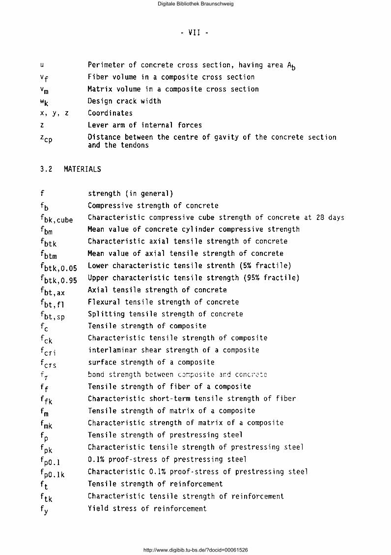
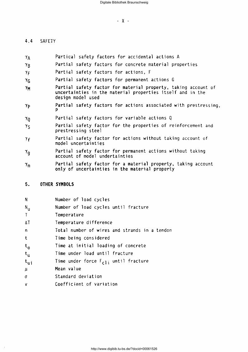
It is not just a matter of scientific curiosity to know more about the true axial strength of an FRP element. Presupposing that such property exists and that it can be reliably tested or forecast, it has an important economic meaning, because it represents the highest level of structural utilization (FRP are expensive materials). A common but crude method to forecast the axial tensile strength is the rule of mixtures [6] in the form of
( 2.1)
in which the contribution of the matrix to the axial tensile strength fc of the composite is entirely neglected. Equ.(2.1) assumes, s. Fig. 2.1, that
(2.2)
which justifies the omission of the contribution of the matrix, especially if the fiber volume is in the practical range of 50 to 70 Vol.-% and if polyesther and epoxy matrices are used. Certainly, the failure strain of the matrix Emu must exceed that of the fiber, a condition which is usually met.
The fiber strength ff is a value usually given by the fiber producer. It must be regarded as a nominal breaking strength. It is derived on basis of tensile tests on bundles of variable numbers of resin-impregnated fibers in order to simulate the composite action within an FRP element with e.g. 50000 to 400000 individual fibers. Suitable practical procedures are applied. By such a procedure the reduction of the variability of the fiber strength and of the effect of the fiber length on its strength by composite interaction between fiber and matrix can be taken into account [6].
From [6] we conclude that the value ff is not the tensile strength of the naked fiber of a certain length but represents its tensile strength in the embedded state. Then we may write for the theoretical mean tensile breaking force of the element
(2.3)
if the value ff is made known by the fiber producer.
It should be pointed out that the forecast with Eq. (2.3) will be a rather crude one. Even if the cross-section is known, it cannot be considered to
Digitale Bibliothek Braunschweig
http://www.digibib.tu-bs.de/?docid=00061526
- 4 -
Fig. 2.1: Stress-Strain Lines of Components and Rule of Mixtures
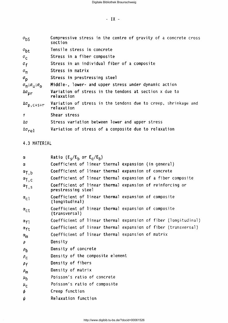
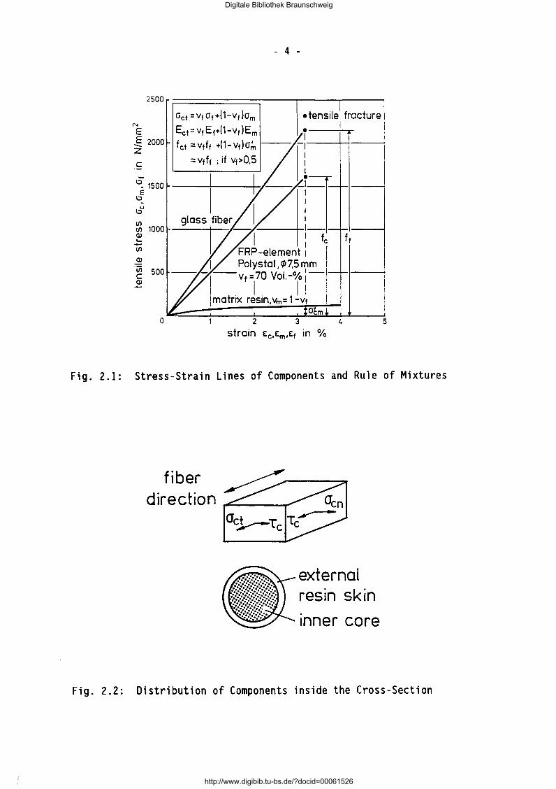
fib er direction
external resin skin
tnner core
Fig. 2.2: Distribution of Components inside the Cross-Section
Digitale Bibliothek Braunschweig
http://www.digibib.tu-bs.de/?docid=00061526
- 5 -
be uniformly interspersed with fibers. As shown by Fig. 2.2, there exists an outer region of resin without fibers.
These remarks show that the prediction of the tensile breaking strength is connected with several uncertainties. Extensive testing becomes inevitable.
2.1.3 Parameters of the axial tensile strength testing
The following parameters influence the axial tensile strength of an FRP element:
a.) cross-section Ac as well as the volume ratios vf and vm of fibers and the matrix;
b.) thickness of external layer of resin on the core of the element;
c.) mechanical properties of the components, inter- and intralaminar shear strength, shear strength between external layer and core;
d.) alignment of fibers and uniformity of fiber distribution, etc.
The parameters a.) to d.) pertain to the FRP e 1 ement in its as -produced state. They all exhibit scatter. Besides these material parameters, the following ones are related to testing:
e.) loading or strain rate;
f.) free length of specimen;
g.) moisture content and temperature of element (pre-conditioning);
h.) type of anchorage
The influence of the material parameters on the tensile strength has been de a 1 t with in ( 1]. The influence of the parameters of testing wi 11 be
discussed in the sequel.
2.1.4 Influence of loading rate
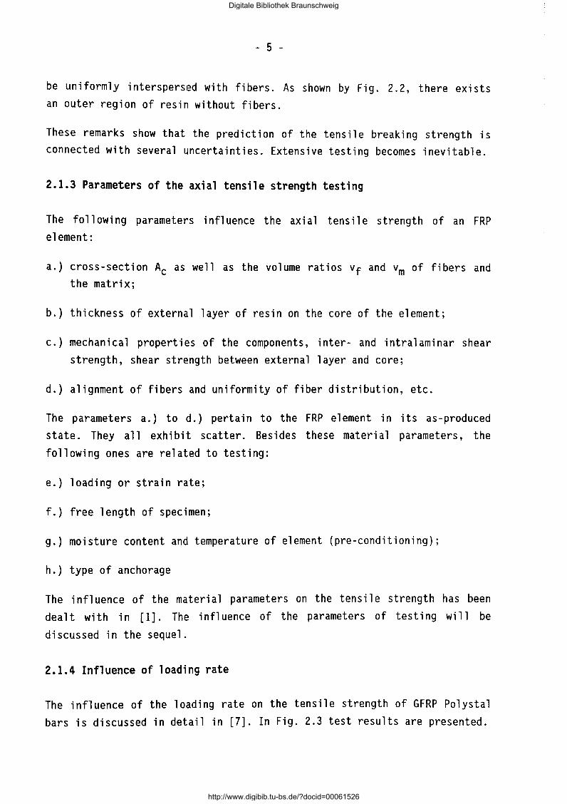
The influence of the loading rate on the tensile strength of GFRP Polystal bars is discussed in detail in [7]. In Fig. 2.3 test results are presented.
Digitale Bibliothek Braunschweig
http://www.digibib.tu-bs.de/?docid=00061526
Feu (vs)
Fcu(0.5kN s
1.00
0.95
0.90
- 6 -
V v-
j
V ·I
0.())250.125 0.250 0.5 tO
loading rate v8
[kNs-1 ]
Fig. 2.3: Related Tensile Strength of GFRP dependent on Loading Rate [7]
As can be seen from Fig. 2.3 the influence of the loading rate vanishes for v8 > 0,250 kN/s. For the subsequent tests the value 0,5 kN/s will be chosen. Similar results were obtained for AFRP Arapree strips with a loading rate of 1 kN/s (= 0,42 °/oo/s). In the range of these loading rates no significantly differing results are obtained if the tests were performed with a constant strain rate.
2.1.5 Influence of free length of specimen
Because the strength of the fi ber is influenced by the density of flaws along its length, the free length of the test specimen will also play a role for the composite strength. In [8] results for GFRP bars with a variable free length are reported. In Fig. 2.4 the results are depicted. The strength values are normalized to the strength of the length of 300 mm. This value will be chosen for the subsequent tensile tests.
Digitale Bibliothek Braunschweig
http://www.digibib.tu-bs.de/?docid=00061526

- 7 -
fck (le)
fck {300) 1.os I lt- short -term tensile
strength {related values
fck with ~ = 300 mm l + ..
+ ... + ....
0,95
t~~ ~y=1121-5,2122lgx (r=0,95) ... ... ----... - .. ... 1---- ...
+ .. -+
i ~ a.~
0 2CXX) 3(XX) 4000 5000
le [mm]
Fig. 2.4: Related Tensile Strength of GFRP Dependent on the Free Length of Specimen [8]
2.1.6 Influence of pre-conditioning
An FRP element is immediately after production completely dry. From then on, it will absorb moisture dependent on the relative humidity of the surrounding air and on the diffusion properties of the matrix resin. Absorption and desorption of moisture are entirely reversible [1]. If the FRP e!emen: is - immediately after production - sheathed by a shrunk-on polymeric cover, the up-take of moisture is slowed down.
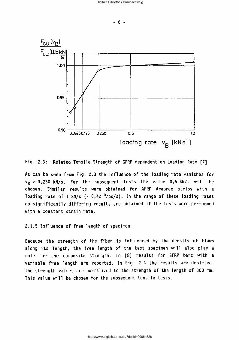
Tests have shown that due to the storage of as-produced unsheathed GFRP bars at 20 oC/65% r.h. and the following absorption of moisture a loss of strength of 3,5% occurs which levels off after a storage time of 8 to 9 weeks [1]. Table 2.1 gives results obtained at different laboratories. For the future test work the FRP material should be preconditioned at the laboratory for a period of about 4 weeks at 20 oC/65 % r.h. prior to testing.
Digitale Bibliothek Braunschweig
http://www.digibib.tu-bs.de/?docid=00061526
- 8 -
Table 2.1: Influence of the Duration of Preconditioning at 20 oc; 65 % r.h. on GFRP [9]
1 aboratory IWB Bayer AG STRABAG Stuttgart
free length (mm) 300 700 910
tensile strength (N/mm2) at the age of
0 days - 1572 -7 days 1599 1510 1588
4 weeks 1549 1501 1573 (3 weeks) 9 weeks 1543 1485 1572
19 weeks 1548 - 1536 27 weeks 1542 1474 1500
2.1.7 Influence of anchorage
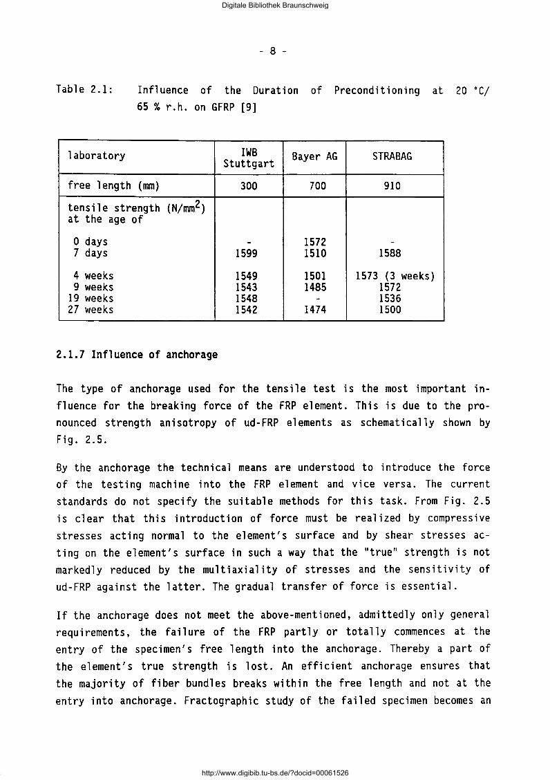
The type of anchorage used for the tensile test is the most important influence for the breaking force of the FRP element. This is due to the pronounced strength anisotropy of ud-FRP elements as schematically shown by Fig. 2.5.
By the anchorage the technical means are understood to introduce the force of the testing machine into the FRP element and vice versa. The current standards do not specify the suitable methods for this task. From Fig. 2.5 is clear that this introduction of force must be realized by compressive stresses acting normal to the element's surface and by shear stresses acting on the element's surface in such a way that the "true" strength is not markedly reduced by the multiaxial ity of stresses and the sensitivity of ud-FRP against the latter. The gradual transfer of force is essential.
If the anchorage does not meet the above-mentioned, admittedly only general requirements, the failure of the FRP partly or totally commences at the entry of the specimen's free length into the anchorage. Thereby a part of the element's true strength is lost. An efficient anchorage ensures that the majority of fiber bundles breaks within the free length and not at the entry into anchorage. Fractographic study of the failed specimen becomes an
Digitale Bibliothek Braunschweig
http://www.digibib.tu-bs.de/?docid=00061526
- 9 -
important tool to judge the efficiency of an anchorage in conjunction with the forecast value of Equ.(2.3).
Fig. 2.5: Multiaxial Strength of FRP
strength reduction by anchorage effects
The testing of an unprotected FRP element in a tensile testing machine with grooved and teethed steel clamps is completely unsuitable. More suitable are hydraulically or pneumatically adjustable and segmented steel clamps with compressible layers to protect the naked bar from injury. Besides this method it is necessary to have an anchorage of high efficiency not only for the short-term tensile testing but also for the long-term and fatigue testing. This leads to anchorages in which the introduction of force into the bar is reparated from the introduction into the test machine.
The development of laboratory anchorages is today an interactive process of experiments and analytical studies and is strongly based on experience. Three basic types have been developed:
a.) clamp anchorage b.) wedge-bond anchorage c.) bond anchorage
Digitale Bibliothek Braunschweig
http://www.digibib.tu-bs.de/?docid=00061526
- 10 -
The types a.) and b.) will be briefly dealt with. The type c.) is not suitable as laboratory anchorage.
Clamp anchorage
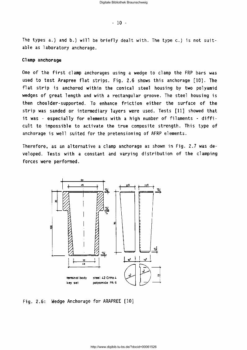
One of the first clamp anchorages using a wedge to clamp the FRP bars was used to test Arapree flat strips. Fig. 2.6 shows this anchorage [10]. The flat strip is anchored within the conical steel housing by two polyamid wedges of great length and with a rectangular groove. The steel housing is then choulder-supported. To enhance friction either the surface of the strip was sanded or intermediary layers were used. Tests [11] showed that it was - especially for elements with a high number of filaments - difficult to impossible to activate the true composite strength. This type of anchorage is well suited for the pretensioning of AFRP elements.
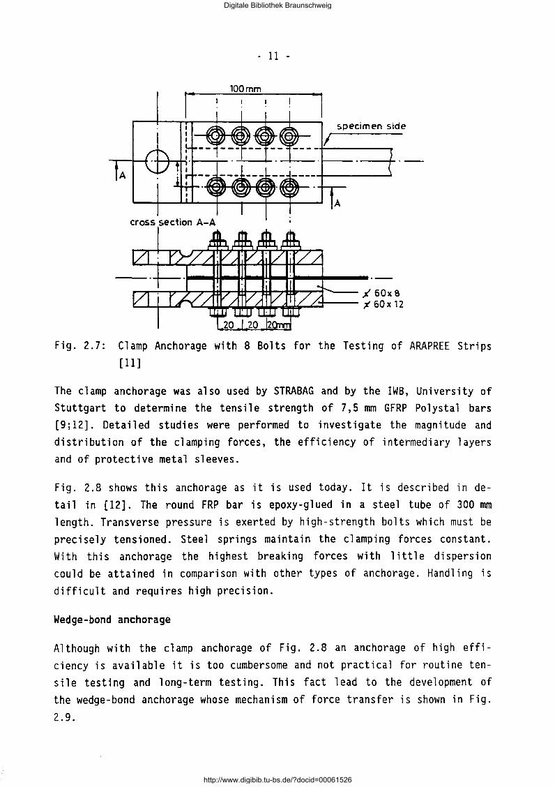
Therefore, as an alternative a clamp anchorage as shown in Fig. 2.7 was developed. Tests with a constant and varying distribution of the clamping forces were performed.
terminal body
key set
"' ..
steel 42 CrMo 4
polyamide PA 6
~ ! ~7 l t 167 t
(jEJ] Fig. 2.6: Wedge Anchorage for ARAPREE [10]
Digitale Bibliothek Braunschweig
http://www.digibib.tu-bs.de/?docid=00061526
- 11 -
100mm
specimen side
I
A
cross section A-A
,.....,'l"""":'~,......-.,........'th,.....J4........,-1+11---7'*1P-..,-r'-- ~ 60 x e u~~::.u.t~u..t;;...J.~.L.:t--- ~ 60 x 12
Fig. 2.7: Clamp Anchorage with 8 Bolts for the Testing of ARAPREE Strips
[11]
The clamp anchorage was also used by STRABAG and by the IWB, University of
Stuttgart to determine the tensile strength of 7,5 mm GFRP Polystal bars
[9;12]. Detailed studies were performed to investigate the magnitude and
distribution of the clamping forces, the efficiency of intermediary layers
and of protective metal sleeves.
Fig. 2.8 shows this anchorage as it is used today. It is described in de
tail in [12]. The round FRP bar is epoxy-glued in a steel tube of 300 mm
length. Transverse pressure is exerted by high-strength bolts which must be
precisely tensioned. Steel springs maintain the clamping forces constant.
With this anchorage the highest breaking forces with little dispersion
could be attained in comparison with other types of anchorage. Handling is
difficult and requires high precision.
Wedge-bond anchorage
Although with the clamp anchorage of Fig. 2.8 an anchorage of high effi
ciency is available it is too cumbersome and not practical for routine ten
sile testing and long-term testing. This fact lead to the development of
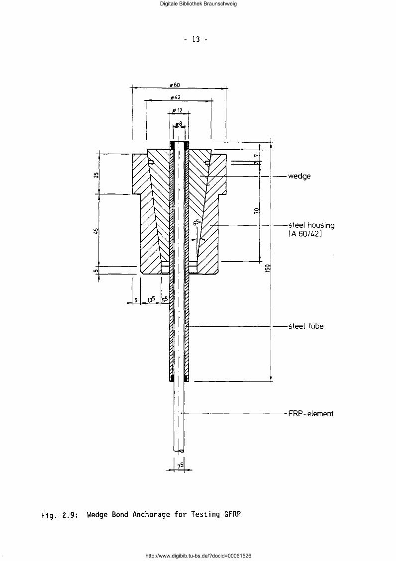
the wedge-bond anchorage whose mechanism of force transfer is shown in Fig.
2.9.
Digitale Bibliothek Braunschweig
http://www.digibib.tu-bs.de/?docid=00061526

- 12 -
steel springs
FRP element
Fig. 2.8: Clamp Anchorage for the Testing of GFRP Bars [12]
As shown in Fig. 2.9, the FRP bar is epoxy-glued on both ends into steel tubes with an inner thread. The steel tubes are then gripped at their rear ends by commercial steel wedges in a conical housing. More details and test results are given in [13]. By this combination of force transfer by bond alone and by bond plus transverse pressure very high breaking forces with a low dispersion of results was attained. This anchorage is equivalent to the clamp anchorage of Fig. 2.8 and by far less cumbersome.
Digitale Bibliothek Braunschweig
http://www.digibib.tu-bs.de/?docid=00061526
- 13 -
tt60
A
0 ....
""7"+----- -steel hous1ng (A 60/42)
1~-------1--steel tube
+----------FRP-element
Fig. 2.9: Wedge Bond Anchorage for Testing GFRP
Digitale Bibliothek Braunschweig
http://www.digibib.tu-bs.de/?docid=00061526
- 14 -
2.2 Short-term Shear Strength
2.2.1 Overview on existing test regulations
Shear tests are used to assess the strength of bond between fiber and resin of an FRP element. In addition to their importance for the generation of design data for structural applications such tests are necessary because they can be employed to assess new sizing systems for the surface treatment. But not only in this respect but also for the characterization of FRP e 1 ements these testing methods became important. Idea 11 y the test method should produce only shear. However it is difficult to meet this condition because of coup 1 i ng effects. Neverthe 1 ess sever a 1 methods for determining the in-plane shear properties of FRP exist in the literature [14;15]. Most of them follow the ASTM - Standard D 2844 [16], which is identical with the European Standard EN 2377 [17] and the DIN 29 971 [18].
2.2.2 Interlaminar shear strength - ILSS
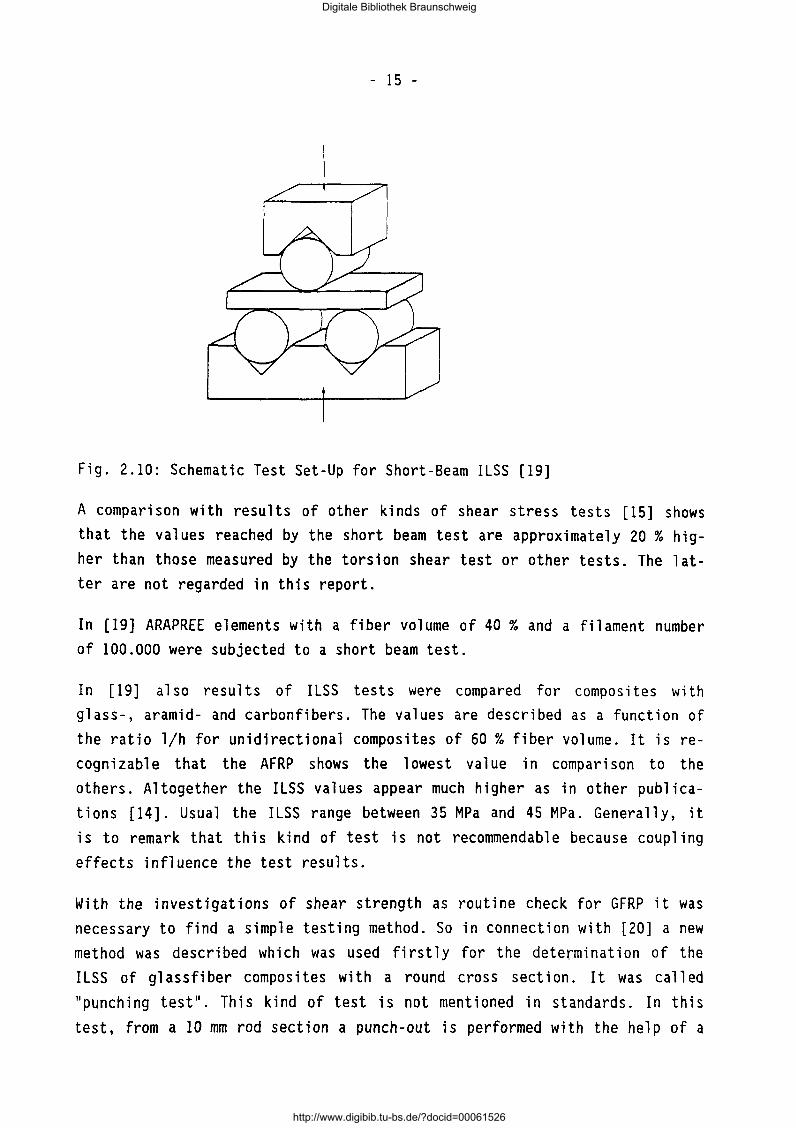
Delamination failures commonly occur in highly loaded composite structures. Several tests have been developed to determine the ILSS, but all have severe limitations. Perhaps the most popular of these tests is the short beam test, which consists of a small unidirectional FRP strip loaded in three point bending. This method based on the elementary beam theory. Experimental work is described in [14;19]. The test set-up is illustrated in Fig.
2.10.
The specimen is supported by two rods; F is the applied load. The compressive roller bearings are exactly defined because the ILSS strongly depends on the ratio 1/h (length/height). The stress distribution along the thickness of the FRP element is a parabolic function which reaches a maximum value at the middle of thickness and zero at upper and lower surface. Thus we
obtain the ILSS:
(2.4)
where Feu is the load at failure, fcri is the ILSS and A is the cross-sec
tional area.
Digitale Bibliothek Braunschweig
http://www.digibib.tu-bs.de/?docid=00061526
- 15 -
Fig. 2.10: Schematic Test Set-Up for Short-Beam ILSS [19]
A comparison with results of other kinds of shear stress tests [15] shows that the values reached by the short beam test are approximately 20 % higher than those measured by the torsion shear test or other tests. The latter are not regarded in this report.
In [19] ARAPREE elements with a fiber volume of 40% and a filament number of 100.000 were subjected to a short beam test.
In [19] also results of ILSS tests were compared for composites with glass-, aramid- and carbonfibers. The values are described as a function of the ratio 1/h for unidirectional composites of 60% fiber volume. It is recognizable that the AFRP shows the lowest value in comparison to the others. Altogether the ILSS values appear much higher as in other publications [14]. Usual the ILSS range between 35 MPa and 45 MPa. Generally, it is to remark that this kind of test is not recommendable because coupling effects influence the test results.
With the investigations of shear strength as routine check for GFRP it was necessary to find a simple testing method. So in connection with [20] a new method was described which was used firstly for the determination of the I LSS of gl assfi ber composites with a round cross section. It was ea 11 ed 11 punching test 11
• This kind of test is not mentioned in standards. In this test, from a 10 mm rod section a punch-out is performed with the help of a
Digitale Bibliothek Braunschweig
http://www.digibib.tu-bs.de/?docid=00061526
- 16 -
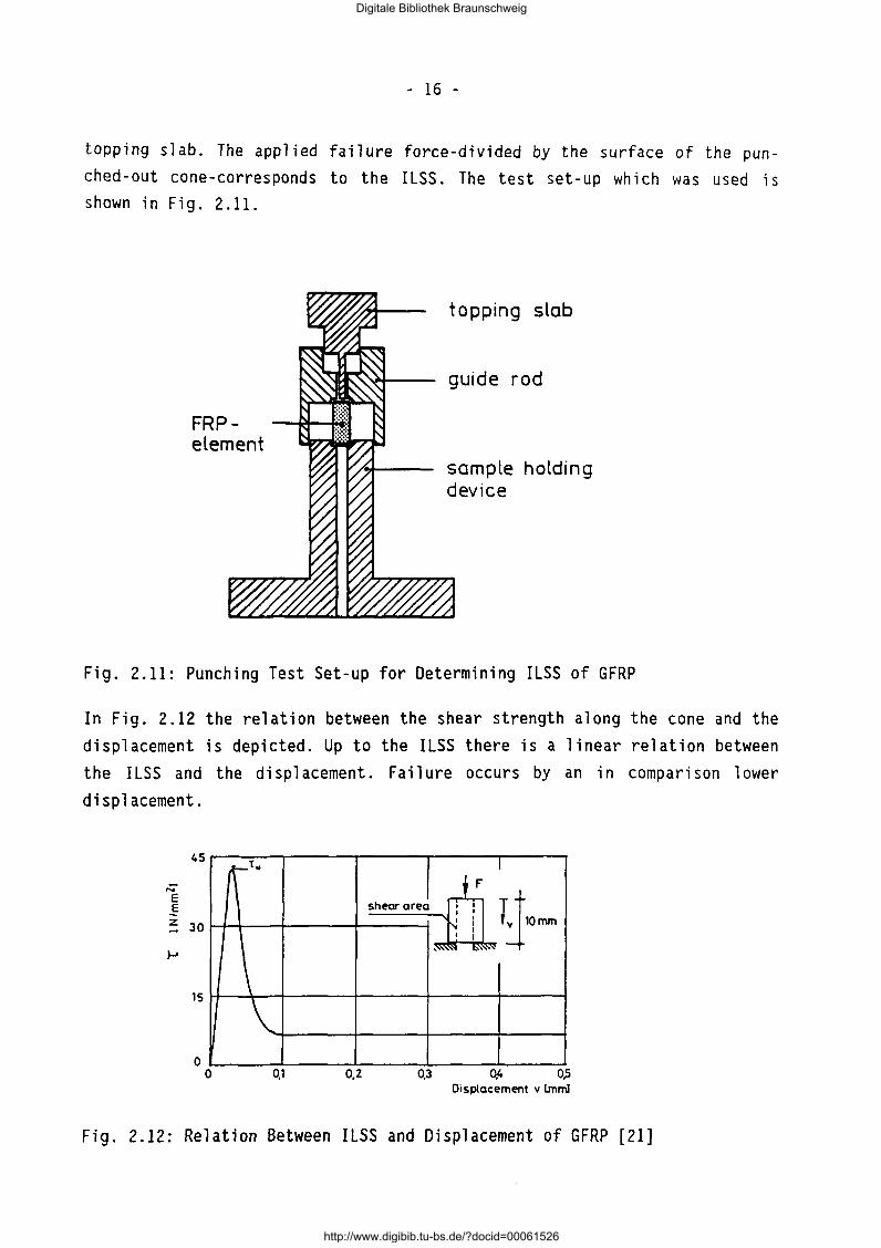
topping slab. The applied failure force-divided by the surface of the punched-out cone-corresponds to the ILSS. The test set-up which was used is shown in Fig. 2.11.
FRPelement
topping slab
guide rod
sample holding device
Fig. 2.11: Punching Test Set-up for Determining ILSS of GFRP
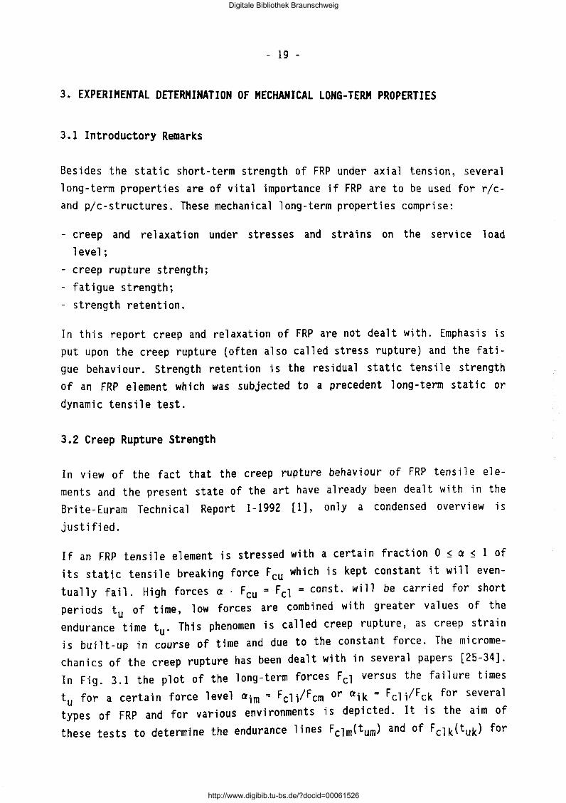
In Fig. 2.12 the relation between the shear strength along the cone and the displacement is depicted. Up to the ILSS there is a linear relation between the ILSS and the displacement. Failure occurs by an in comparison lower displacement.
e .§
45
z 30
15
0
t\t"
\ \
0 0,1
I F
I
•h«ra•ea ; ; Tj N ! v 10rnm
I I
~~ IS'~
0,2 0,3 Oft 0,5 Displacement v lmml
Fig. 2.12: Relation Between ILSS and Displacement of GFRP [21]
Digitale Bibliothek Braunschweig
http://www.digibib.tu-bs.de/?docid=00061526

- 17 -
More details of this test (loading rate, specimen length} are given in [ 21] . It is important, that the tests are performed carefu 11 y because of the sensitive test set-up.
2.2.3 Surface shear strength
The quantification of the force transfer between the fiber containing core and its outer coating which may consists of either the same of a different resin is reffered to as surface shear strength. This property of FRP will also influence the transfer length.
The bond strength is very important for the force transfer between the FRP element and the steel tube or housing of a post-tensioning anchorage. The definitions of the various types of bond strength are illustrated as follows:
,.---- surface shear strength
fTcs
FRP- \\-----+-- bond strength element --+--~lob f-r
mortar
interlaminar shear strength
fTci
Mostly the surface shear strength is determined by "pull-out" tests (Fig. 2.13}. Thereby the FRP element is loaded by a tensile force and similar to the ILSS the pertinent displacement will be recorded. The results are presented as shear stress-displacement diagrams.
Within the scope of tests with GFRP [22;23;24] a mean surface shear strength frcs of 30 MPa was measured for bars embedded in a sand-resin mortar. As the bond fa i1 ure occurred at the contact surface of the bar with the mortar all other strength values were in excess of frcs·
Digitale Bibliothek Braunschweig
http://www.digibib.tu-bs.de/?docid=00061526

- 18 -
bond length ( 30 mm 1
without bord
FRP- element
F
Fig. 2.13: Pull-Out Test Set-up for Determining Surface Shear Strength [22]
The surface shear strength and the chosen test method are not the object of any standard. Also in the literature only a small number of publications exist. Further research is necessary.
Digitale Bibliothek Braunschweig
http://www.digibib.tu-bs.de/?docid=00061526
- 19 -
3. EXPERIMENTAL DETERMINATION OF MECHANICAL LONG-TERM PROPERTIES
3.1 Introductory Remarks
Besides the static short-term strength of FRP under axial tension, several long-term properties are of vital importance if FRP are to be used for r/cand plc-structures. These mechanical long-term properties comprise:
- creep and relaxation under stresses and strains on the service load level ;
- creep rupture strength; - fatigue strength; - strength retention.
In this report creep and relaxation of FRP are not dealt with. Emphasis is put upon the creep rupture (often also called stress rupture) and the fatigue behaviour. Strength retention is the residual static tensile strength of an FRP element which was subjected to a precedent long-term static or
dynamic tensile test.
3.2 Creep Rupture Strength
In view of the fact that the creep rupture behaviour of FRP tensile elements and the present state of the art have already been dealt with in the Brite-Euram Technical Report 1-1992 [1], only a condensed overview is
justified.
If an FRP tensile element is stressed with a certain fraction 0 ~ a ~ 1 of its static tensile breaking force Feu which is kept constant it will eventually fail. High forces a . Feu= Fcl = const. will be carried for short peri ads tu of time, low forces are combined with greater values of the endurance time tu. This phenomen is called creep rupture, as creep strain is built-up in course of time and due to the constant force. The micromechanics of the creep rupture has been dealt with in several papers [25-34]. In Fig. 3.1 the plot of the long-term forces Fcl versus the failure times
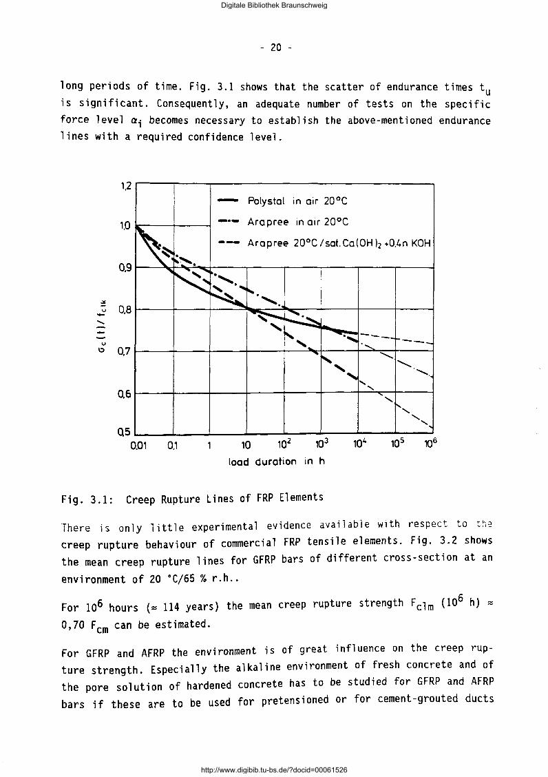
tu for a certain force level aim= Fcli/Fcm or aik = Fcli/Fck for several types of FRP and for various environments is depicted. It is the aim of
these tests to determine the endurance lines Fclm<tum) and of Fclk(tuk) for
Digitale Bibliothek Braunschweig
http://www.digibib.tu-bs.de/?docid=00061526
- 20 -
long periods of time. Fig. 3.1 shows that the scatter of endurance times t is significant. Consequently, an adequate number of tests on the specifi~ force level a; becomes necessary to establish the above-mentioned endurance lines with a required confidence level.
1,2
- Polys tal in air 20°C
1,0 -·- Arapree in air 20°C
~ -- Arapree 20°C/sat.Ca(0Hh .O.L.n KOH
0.9
~
~ 0,8 ........
u 1:1 0,7
Q6
QS 0.01
'1:, ~~. ~~
0.1
~-.,
' . ., ~-~ '· ~' 'f-: -~ ~ '· "' "-,
'
10
load duration in h
Fig. 3.1: Creep Rupture Lines of FRP Elements
-._._._ ,_ ___ ...........
'-.... ...........
........... ...... ......
.... , 1',
' .........
There is only little experimental evidence available with respect to t~.::
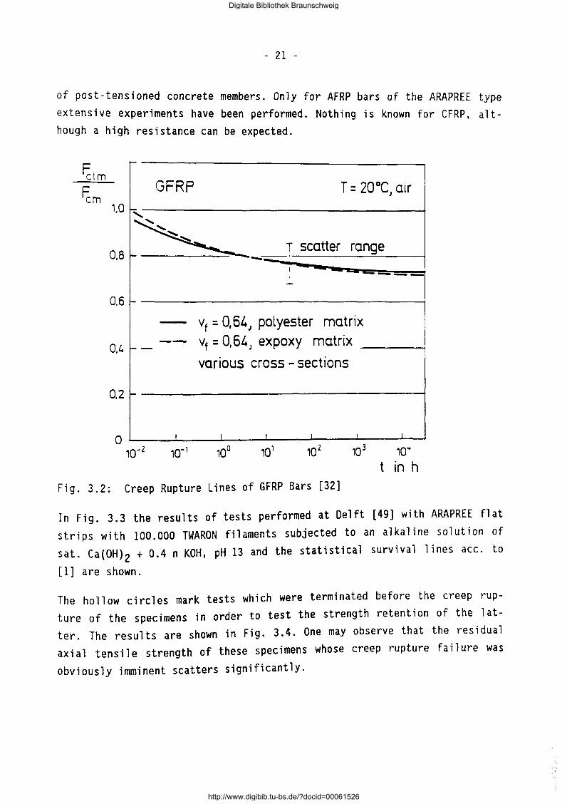
creep rupture behaviour of commercial FRP tensile elements. Fig. 3.2 shows the mean creep rupture lines for GFRP bars of different cross-section at an
environment of 20 oC/65% r.h ..
For 106 hours (= 114 years) the mean creep rupture strength Fclm (106 h) =
0,70 Fern can be estimated.
For GFRP and AFRP the environment is of great influence on the creep rupture strength. Especially the alkaline environment of fresh concrete and of the pore solution of hardened concrete has to be studied for GFRP and AFRP bars if these are to be used for pretensioned or for cement-grouted ducts
Digitale Bibliothek Braunschweig
http://www.digibib.tu-bs.de/?docid=00061526
- 21 -
of post-tensioned concrete members. Only for AFRP bars of the ARAPREE type extensive experiments have been performed. Nothing is known for CFRP, although a high resistance can be expected.
~lm ~m
1,0
0.8
0.6
O,l.
0,2
r-
GFRP T = 20°C a1r J
" ~ '~~ ~ --I scatter range
1 ------~
- vf = 0,64J polyester matrix
--t-- vt = 0, 64 J expoxy matrix
various cross -sections
r-
I I I I I I
10 3 10 ..
t in h Fig. 3.2: Creep Rupture Lines of GFRP Bars [32]
In Fig. 3.3 the results of tests performed at Delft [49] with ARAPREE flat
strips with 100.000 TWARON filaments subjected to an alkaline solution of sat. Ca(OH)
2 + 0.4 n KOH, pH 13 and the statistical survival lines ace. to
[l] are shown.
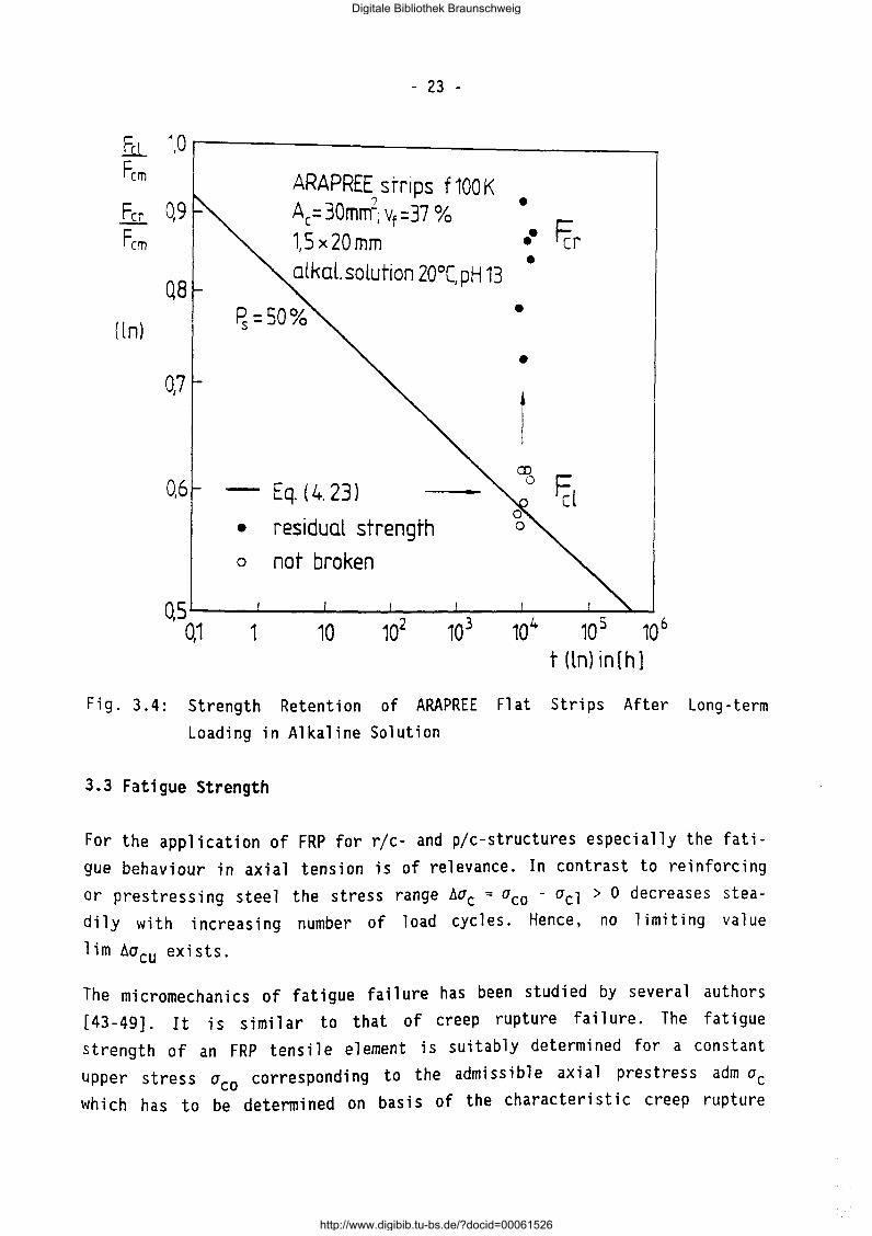
The hollow circles mark tests which were terminated before the creep rupture of the specimens in order to test the strength retention of the latter. The results are shown in Fig. 3.4. One may observe that the residual
axi a 1 tens i 1 e strength of these specimens whose creep rupture failure was
obviously imminent scatters significantly.
Digitale Bibliothek Braunschweig
http://www.digibib.tu-bs.de/?docid=00061526

fu Fcm
( ln)
- 22 -
1,0
ARAPREE f 100K; 1,5 x 20 mm ?
0,9 Ar_=30mnr;vf =37% alkaline solution; 20°(; pH 13 fck= 30kN; fcm= 36 kN
0,8 • broken
o not broken
0,7
• 0,6
- Eq. {4. 23)
QsQ~1--~,---,~o---1~0-2 --,~o-3 --~10-4 --~10~5 ~~,o6
t (ln) in [ h]
Fig. 3.3: Creep Rupture Tests of ARAPREE Flat Strips in Alkaline Solution [35]
The most extensive tests were carried out by [35-37]. Resin-impregnated sglass and aramid fiber bundles were used. Test times were up to 104 hours. Especially the methodology of test evaluation will serve here as guideline in connection with the theoretical forecast models of the sources [38-42].
The evaluation of the scarce experimental data necessitate extensive testing of the creep rupture behaviour.
Digitale Bibliothek Braunschweig
http://www.digibib.tu-bs.de/?docid=00061526
fu_ 1,0 Fe m
Fer 0,9 Fe m
Q8
( ln)
0,7
0,6
- 23 -
ARAPREE strips f100K ?
Ac= 30mm-; vf =37 % 1,5 x20 mm alkal.solution 20°C,pH 13
Eq. (4. 23}
• residual strength
o not broken
• •• Fcr •
•
•
I CD
0 ~l
QS----~--~--~--~--~----L-~ 0,1 1 10 102 103 104 10 5 10 6
t(ln)in[h]
Fig. 3.4: Strength Retention of ARAPREE Flat Strips After Long-term
Loading in Alkaline Solution
3.3 Fatigue Strength
For the application of FRP for r/c- and plc-structures especially the fati
gue behaviour in axial tension is of relevance. In contrast to reinforcing
or prestressing steel the stress range Aac = aco - acl > 0 decreases stea
dily with increasing number of load cycles. Hence, no limiting value
lim Aacu exists.
The micromechanics of fatigue failure has been studied by several authors
[43-49]. It is similar to that of creep rupture failure. The fatigue
strength of an FRP tensile element is suitably determined for a constant
upper stress a corresponding to the admissible axial prestress adm ac eo
which has to be determined on basis of the characteristic creep rupture
Digitale Bibliothek Braunschweig
http://www.digibib.tu-bs.de/?docid=00061526

- 24 -
line Fclk(t) for the time range of the service life. Hence with the constant force
( 3. I)
and the variable lower force
(3.2)
the S-N-1 ines with an adequate number of identical tests for the specific force range AFc = Fco - Fcl can be experimentally determined.
The fatigue strength of FRP e 1 ements depends on a series of parameters. First of all the type of fiber is of great influence. CFRP have the highest fatigue strength, with that of AFRP being only slightly less. The fatigue strength of GFRP is significantly lower. Fig. 3.5 shows fatigue test lines (mean values) from [50]. The type of matrix resin is of influence. Progressive matrix cracking seems to be detrimental.
160 ' Polystal ~ 7.5 mm : in air, 20°C
E-gloss+epoxy 1
1 E -glass+ polyester
Ql ::l C7l
0 ~0~------~------~~----~------~ ~ v, = 0.55
cr0 = 736N/mm 2
; 0.48 fetk
oL-------~------~~~6~~7~----:,ae 10' 105 106 N::2·10 10
load cycles N
Fig. 3.5: Fatigue Behaviour of GFRP Polystal Bars Dependent on Matrix
Resin [SO]
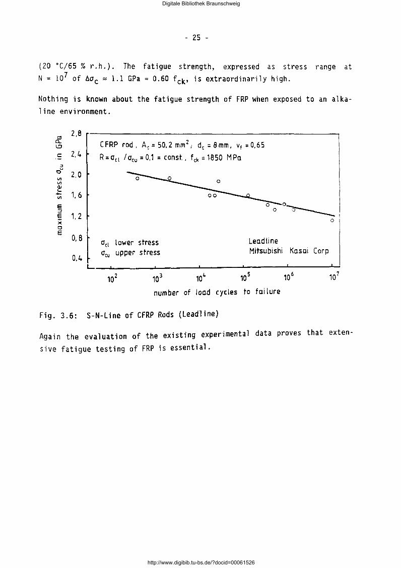
Fig. 3.6 shows the results of fatigue tests performed with CFRP rods (leadline, Japan) with a constant stress ratio R = acllaco = 0,1
Digitale Bibliothek Braunschweig
http://www.digibib.tu-bs.de/?docid=00061526
- 25 -
(20 OC/65% r.h.). The fatigue strength, expressed as stress range at N = 107 of hac= 1.1 GPa = 0.60 fck' is extraordinarily high.
Nothing is known about the fatigue strength of FRP when exposed to an alkaline environment.
::J
o'"' Ill Ill <lJ '--Ill E ~
E X 0 E
2,8
2.4
2,0
1.6
1, 2
0, 8
0,4
CFRP rod, A,= 50,2 mm 2 ; d, = Bmm, Yt =0,65
R=a,1 lacu = 0,1 = const., f,k = 1850 MPa
0 0-o--.____
o,1 lower stress a,u upper stress
Lead line Mitsubishi Kasai Corp
0
L--~------_.------~------~--------~------~
number of load cycles to failure
Fig. 3.6: S-N-Line of CFRP Rods (leadline)
Again the evaluation of the existing experimental data proves that exten
sive fatigue testing of FRP is essential.
Digitale Bibliothek Braunschweig
http://www.digibib.tu-bs.de/?docid=00061526

- 26 -
4. TEST METHODS OF IBMB FOR THE DETERMINATION OF MECHANICAL PROPERTIES OF UNIDIRECTIONAL-FRP-ELEMENTS
4.1 Short-term Tensile Testing
4.1.1 Main requirements for the test set-up and testing procedures
Because of the great significance of the short term tensile strength for the quality control and for the classification of the FRP-material the test
set-up have to meet several requirements:
- a suitable anchorage must be available, s. 2.1.7
pre-conditioning of the FRP-bars prior to testing is necessary, e.g. four
weeks at 20 oc and 65 % r.h.
- an approved tensile testing machine according to DIN 51 300 and ISO 5893
must be available.
4.1.2 Testing machine
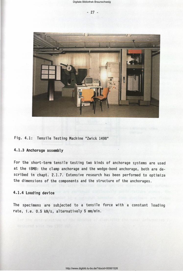
All tests were performed in a conventional tensile testing machine "Zwick 1498" with a maximal tensile force of 100 kN. Various grips allow the testing of several kinds of anchorages. Fig. 4.1 and 4.2 show the
testing machine with measuring devices.
Digitale Bibliothek Braunschweig
http://www.digibib.tu-bs.de/?docid=00061526
- 27 -
Fig. 4.1: Tensile Testing Machine "Zwick 1498"
4.1.3 Anchorage assembly
For the short-term tensile testing two kinds of anchorage systems are used at the iBMB: the clamp anchorage and the wedge-bond anchorage, both are described in chapt. 2.1.7. Extensive research has been performed to optimize the dimensions of the components and the structure of the anchorages.
4.1.4 Loading device
The specimens are subjected to a tensile force with a constant 1 oadi ng rate, i.e. 0.5 kN/s, alternatively 5 mm/min.
Digitale Bibliothek Braunschweig
http://www.digibib.tu-bs.de/?docid=00061526

- 28 -
controller
~~
r4 _, ~
Fig. 4.2: Testing Device
4.1.5 Measuring devices
~ --~ -
I
cross head
moving cross member
anchorage device (clamping wedge anchorage)
FRP- element
stationary cross member
The measurement of the axial tensile force and the corresponding deformation of the specimen are performed continuously until failure occurs. The test data are recorded on a personal computer. Some specimens are fitted with strain gauges (5 mm) on their free length and on the steel housing of
the wedge-bond anchorage to record deformations.
For the determination of the modulus of elasticity the axial deformation is
measured with two LVDT W5E.
Digitale Bibliothek Braunschweig
http://www.digibib.tu-bs.de/?docid=00061526
- 29 -
4.2 Creep Rupture Testing
4.2.1 Main requirements for the test set-up and testing procedures
The test set-up and the measuring devices for the determination of the creep rupture strength of an FRP tensile element have to meet several requirements:
- static long-term forces - in the same magnitude as the static short-term tensile breaking force - must be generated and maintained constant over a long period of time. Control and adjustment of force must be possible,
- the initial axial strain and the time-dependent creep strain must be recorded reliably and accurately during long-term testing,
a single bar anchorage with a high static efficiency factor must be available so that the creep rupture strength of the FRP element is not influ
enced by anchorage effects,
- the FRP element shall be subjected on a certain part of its free length to an environment similar to the future conditions in practice.
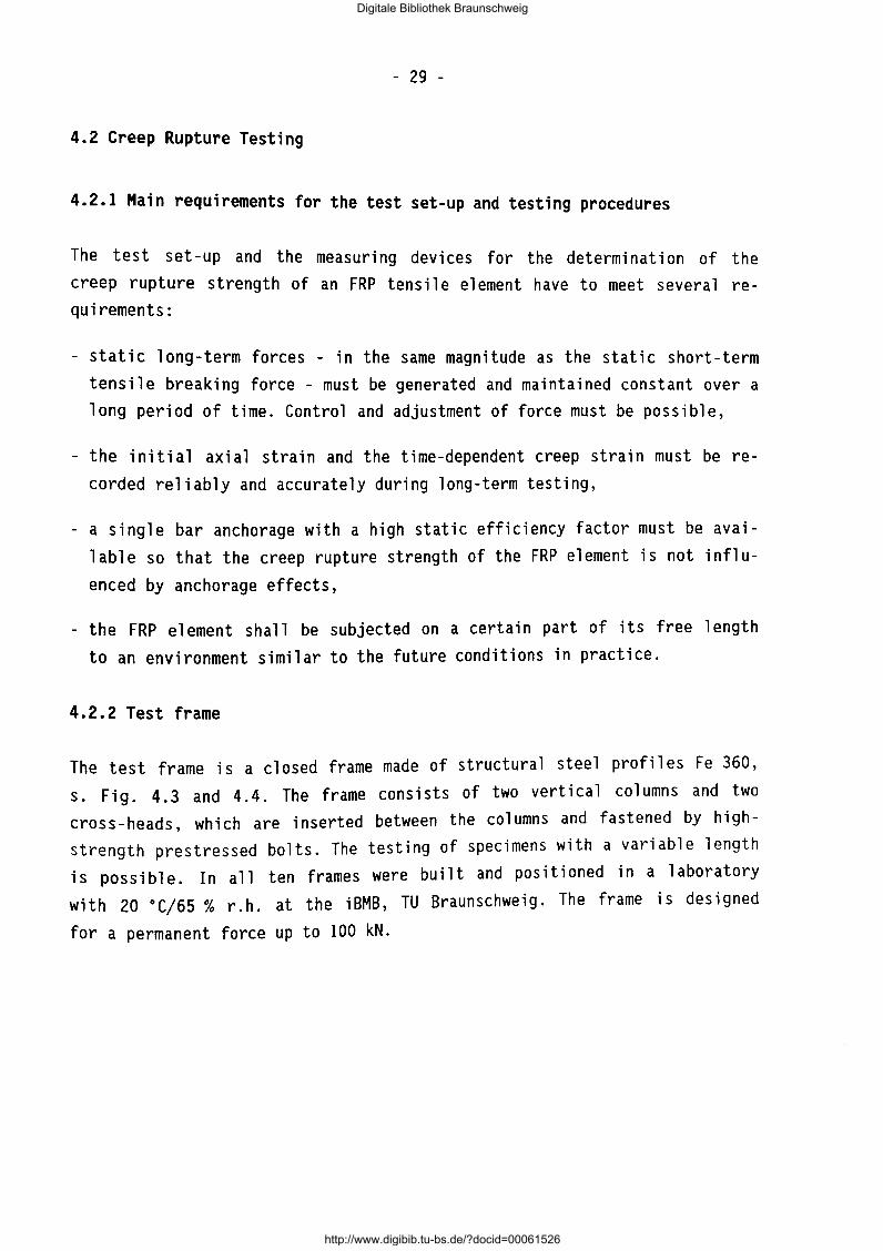
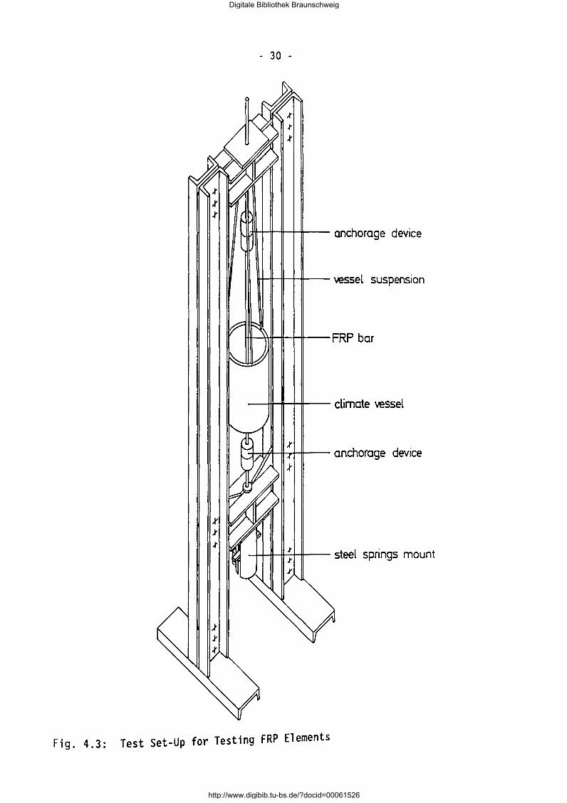
4.2.2 Test frame
The test frame is a closed frame made of structural steel profiles Fe 360, s. Fig. 4.3 and 4.4. The frame consists of two vertical columns and two cross-heads, which are inserted between the columns and fastened by highstrength prestressed bolts. The testing of specimens with a variable length is possible. In all ten frames were built and positioned in a laboratory with 20 oC/65% r.h. at the iBMB, TU Braunschweig. The frame is designed
for a permanent force up to 100 kN.
Digitale Bibliothek Braunschweig
http://www.digibib.tu-bs.de/?docid=00061526
- 30 -
anchorage device
vessel suspension
---ttt--+-+-11--- climate vessel
steel springs mount
Fig. 4.3: Test Set-Up for Testing FRP Elements
Digitale Bibliothek Braunschweig
http://www.digibib.tu-bs.de/?docid=00061526
- 31 -
·,
Fig. 4.4: Photograph of Test Set-up
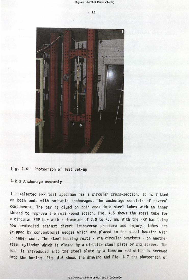
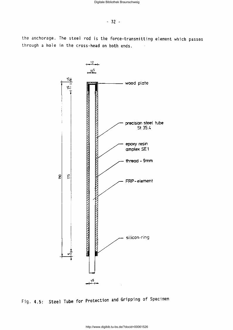
4.2.3 Anchorage assembly
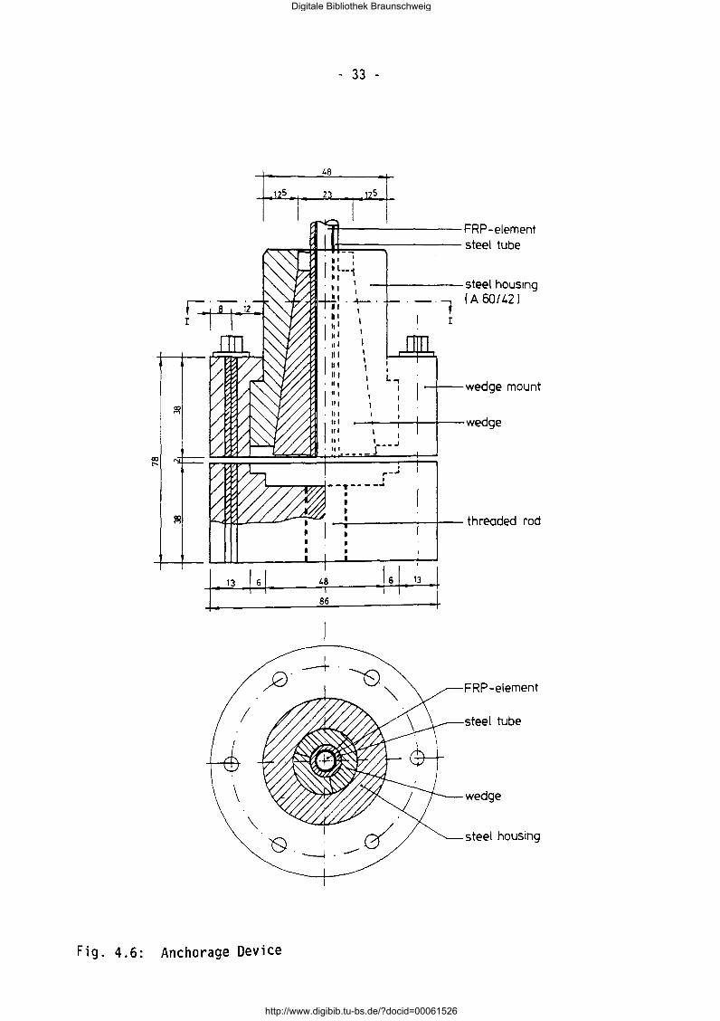
The selected FRP test specimen has a circular cross-section. It is fitted on both ends with sui tab 1 e anchorages. The anchorage consists of sever a 1 components. The bar is glued on both ends into steel tubes with an inner thread to improve the resin-bond action. Fig. 4.5 shows the steel tube for a circular FRP bar with a diameter of 7.0 to 7.5 mm. With the FRP bar being now protected against direct transverse pressure and injury, tubes are gripped by conventional wedges which are placed in the steel housing with an inner cone. The steel housing rests - via circular brackets - on another steel cylinder which is closed by a circular steel plate by six screws. The load is introduced into the steel plate by a tension rod which is screwed into the boring. Fig. 4.6 shows the drawing and Fig. 4.7 the photograph of
Digitale Bibliothek Braunschweig
http://www.digibib.tu-bs.de/?docid=00061526
- 32 -
the anchorage. The steel rod is the force-transmitting element which passes through a hole in the cross-head on both ends.
11'1 ......
12 I • • I
precision steel tube St 35.4
epoxy resin amplex SE1
thread- 9mm
FRP- element
silicon-ring
F" Steel Tube for Protection and Gripping of Specimen lg. 4.5:
Digitale Bibliothek Braunschweig
http://www.digibib.tu-bs.de/?docid=00061526
- 33 -
48
23
'fl---------FRP-element ~~..J~-1+;;:;:::==::::;------ steel tube
I: , 1·1-
Fig. 4.6: Anchorage Device
48 I
86
1 1 I
-+------steel housing . -. f (A 60/42)
I I
I I
L.., I ~--wedge mount
-H-, :I
FRP-element
steel tube
wedge
steel hous1ng
Digitale Bibliothek Braunschweig
http://www.digibib.tu-bs.de/?docid=00061526

- 34 -
Fig. 4.7: Photograph of Anchorage Element
4.2.4 Loading device
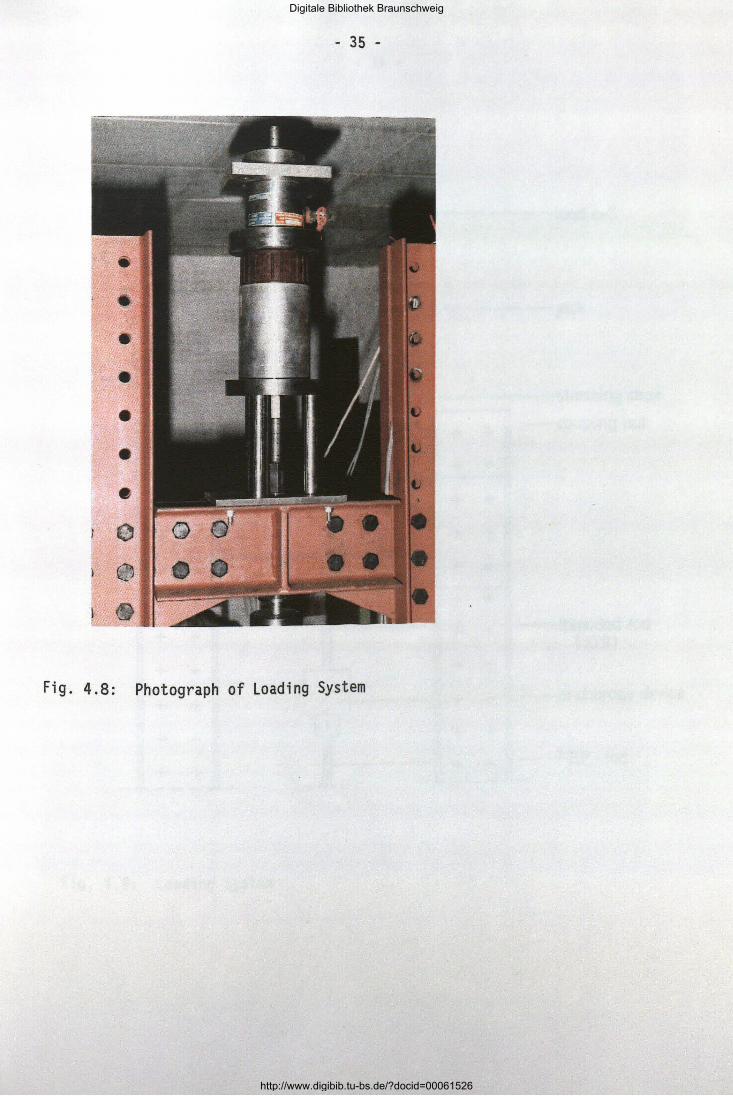
The specimen is stressed at the upper cross-head by a hydraulic jack with a center hole. The jack is seated on a jack chair to permit the tightening of the nut on the bar, until the desired force is attained. The force - during initial loading and at each readjustment of force - is measured with a load cell. The loading rate is 0.5 kN/s. Fig. 4.8 and 4.9 show the loading device. Once, the force is attained the jack and the load cell will be remo ved after an initial observation period of 24 hours.
Digitale Bibliothek Braunschweig
http://www.digibib.tu-bs.de/?docid=00061526
• • • 0
e
- 35 -
Fig. 4.8: Photograph of Loading System
Digitale Bibliothek Braunschweig
http://www.digibib.tu-bs.de/?docid=00061526

- 36 -
Jl I
L l
I I I I
h-.-- .--1
+ + + +
+ + I + + ------ -------+
I I + + + I I + + + +
I I I I
+ + + + I I + + + + I I
+ + ~ ~ + + ------ I ------+ + + +
+ + + +
+ + + + I
+ + I
i + +
+ __j._ LlJ -+- ...!...
I + + ~"--
+ + ---- - -...l
_ ... L.---
Fig. 4.9: Loading System
--
load cell
jack
stressing chair
coupling nut
--t hreaded rod ( 10.9)
--a nchorage device
--F RP- rod -
Digitale Bibliothek Braunschweig
http://www.digibib.tu-bs.de/?docid=00061526

- 37 -
4.2.5 Springs
Load constancy during the testing time is attained by a package of plate
springs, s. Fig. 4.10. The actual spring package is enclosed by a steel cy
linder tube. Fig. 4.11 shows the calibration line of the chosen spring package.
- r-----.-- - - - ----
lil j
I + + + + + + I + +
+ + I + +
~ ----------
~ + + I + + I I
+ + + + + + + I I + I I
+ + + + I I + + + + I I ----------
~ ~~f,.. ·~-- -:::~-
~r-i~-;. =t=~ ~~~-=B '--- ---. --~ ,..........
I ""-----------
+ + I + +
+ + I + + I
+ + + +
,I I
Fig. 4.10: Load Constancy by Steel Plate Springs
--FRP-element
-anch orage device
-threa ded rod
-dial gage
--steel spnng 00• 51• 6) (A 1
--spn ng mount
ll
Digitale Bibliothek Braunschweig
http://www.digibib.tu-bs.de/?docid=00061526

- 38 -
120
110
100
90
-,-----F measured by load cell I
-f- Al measured by dial gage I
80 z ..>(. - 70 ~
I
u..
~ GO
u 0 u.. 50
40
30
20
10
0
~ n= 10 _. n- 20
V V I /
I V I /
Springs A 100 X 51 X 6
I / --I
n: number of I i
1/ V springs -
j/ 0 20 40 60
Spring deformation AI tmml
Fig. 4.11: Calibration Lines of Springs (A lOO x 51 x 6)
In course of time the spring package will extend due to the specimen's creep. The magnitude of extension serves for the control of load constancy. Consequently, the extension is measured on two sides with 1/100 mm dial gages. It is planned to complete this measuring system with an LVOT. If the force falls still to a specified lower boundary value readjustment is ne-
cessary and possible.
Pilot tests have proved the suitability of this equipment. Testing accor
ding to the test program has commenced.
4.2.6 Measuring devices
The measuring devices for the force and the spring deformation have already been described. The measurement of the axial tensile strain of the specimen is performed by two LVOT WSE (total displacement 5 mm) of H&B MeBtechnik
Digitale Bibliothek Braunschweig
http://www.digibib.tu-bs.de/?docid=00061526
- 39 -
edge
-+------- FRP-element
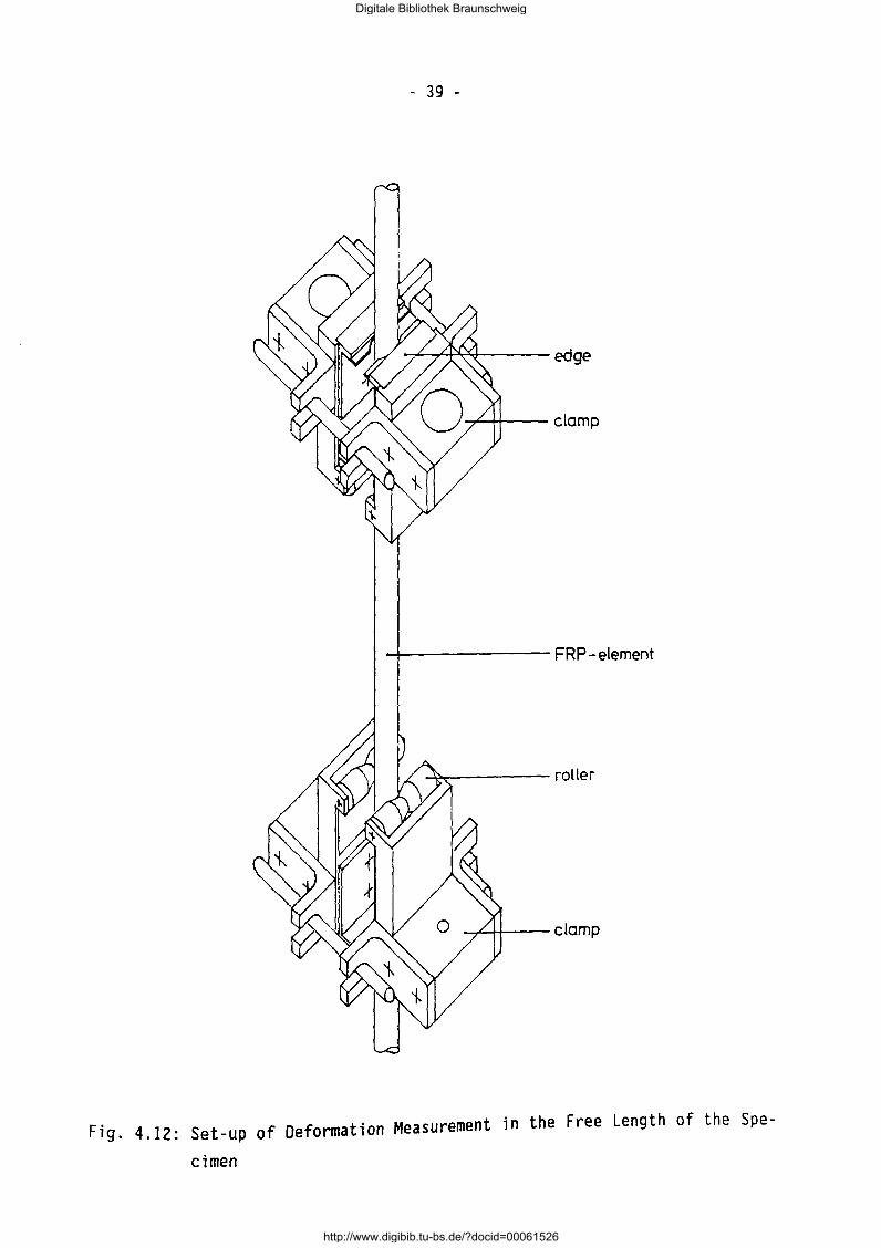
Fig. 4.12: Set-up of Deformation Measurement in the Free Length of the Spe
cimen
Digitale Bibliothek Braunschweig
http://www.digibib.tu-bs.de/?docid=00061526
- 40 -
over a gage length of 200 mm. The gage length is situated within the environment vessel. The bridging of the gage length is performed with bars made from invar steel whose thermal dilatancy is negligible. The upper ends of the invar bars are coupled with the plungers of the LVDT.
Fig. 4.12 shows a principal drawing of the measurement set-up. The device consists of two clamps with rollers and edges, made from Cr-Ni-steel. The clamping force and the edges were chosen in such a way that the bar is not adversely injured (control by SEM investigation was performed).
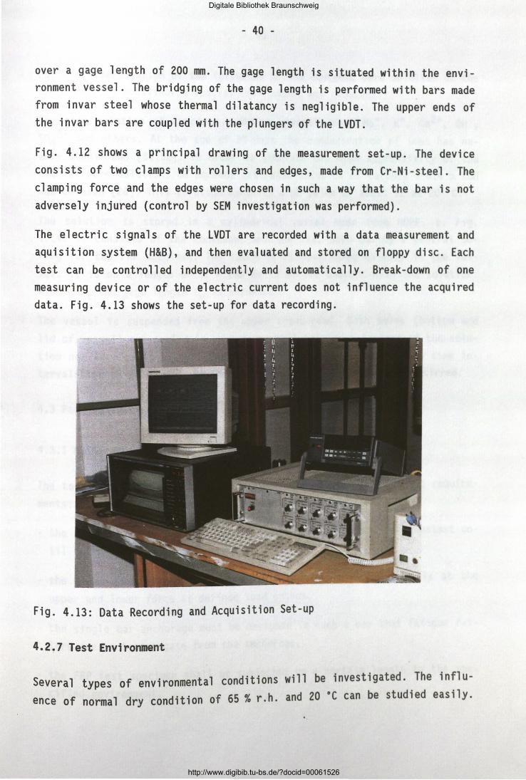
The electric signals of the LVDT are recorded with a data measurement and aquisition system (H&B), and then evaluated and stored on floppy disc. Each test can be controlled independently and automatically. Break-down of one measuring device or of the electric current does not influence the acquired data. Fig. 4.13 shows the set-up for data recording.
Fig. 4.13: Data Recording and Acquisition Set-up
4.2!7 Test Environment
Several types of environmental conditions will be investigated. The influence of normal dry condition of 65% r.h. and 20 ·c can be studied easily.
Digitale Bibliothek Braunschweig
http://www.digibib.tu-bs.de/?docid=00061526

- 41 -
For the investigation of the influence of the concrete pore solution on the creep rupture behaviour a special environment was choosen.
The pore solution of concrete contains several ions: Na+, K+, ca2+, OW, so4
2- and others. At the age of 28 days the concentration of ions has nearly stabilized [51;52]. In order to simulate the high aggressivity of the natural pore solution, an aqueous saturated solution of Ca(OH) 2 + 0.4 n KOH was choosen [26]. This solution exhibits a pH value of about 12 at 20 oc.
The solution is stored in a cylindrical vessel made from HOPE, s. Fig. 4.14. It consists of the container and the lid, both having a central boring for the FRP specimen. The specimen is positioned axially in the vessel. It is on a length of Lt = 250 mm in direct contact with the solution.
Within Lt the gage length Le is situated.
The vessel is suspended from the upper cross-head. Both holes (bottom and lid of vessel) are sealed in such a way that neither a leakage of the solution nor an ingress of air (carbon dioxide) can occur. At certain time intervals the pH value will be controlled and the solution will be stirred.
4.3 Fatigue Testing
4.3.1 Main requirements for the test set-up and testing procedures
The test set-up and the measuring devices must meet the following require
ments:
- the upper force Fu and the lower force F1 must be maintained constant un
til failure of the FRP bar occurs,
- the axial strain must be recorded continuously or automatically at the
upper and lower force at defined load cycles,
- the single bar anchorage must be designed in such a way that fatigue fai
lure does not propagate from the anchorage,
- the FRP test specimen shall be subjected on a certain length to the spe
cified environment.
Digitale Bibliothek Braunschweig
http://www.digibib.tu-bs.de/?docid=00061526

0 ....:t tT'I
0 ....:t
0 N
0-rin
silicon ea 2"/21. 96.06
Fig. 4.14: Environment Vessel
- 42 -
~ 225
I et> 225 X 20 5
Digitale Bibliothek Braunschweig
http://www.digibib.tu-bs.de/?docid=00061526
- 43 -
4.3.2 Test frame and anchorage
In all three test frames were built. They are designed as shown in Fig. 4 .15. The same anchorage elements as for the creep rupture testing were chosen.
4.3.3 loading device
The loading is performed hydraulically with a jack of 100 kN force-controlled at the lower cross-head. The jack has a central hole to accommodate the threaded steel tension bar which is connected with the lower anchorage of the specimen.
Fatigue loading is performed with a frequency of about 5 Hz. The loading is controlled and measured by a 100 kN load cell (± 0.5 kN).
4.3.4 Measuring devices
Because of the vibrations during fatigue testing a measuring system with LVDT used for creep rupture testing is not suitable. It is planned to use electric strain gages, situated on the free length, which have to be sealed from contact with the solution. In addition slip of the bar at its entry into the anchorage and deformations of the steel housing will be measured.
Digitale Bibliothek Braunschweig
http://www.digibib.tu-bs.de/?docid=00061526

r--
I rJ.
f7 ·'\]
~~~ '~ ~ I I I
4-.- .!
I : I
Fig. 4.15: Test Frame for Fatigue Testing (Photograph - Side and Front View)
r--
--
:
-f-
-
~
I
oncho<ogo dMce IA601L2l
FRP-etemenl
lood cell
LVDT
Digitale Bibliothek Braunschweig
http://www.digibib.tu-bs.de/?docid=00061526

- 45 -
5. INTERNAL STANDARDIZATION OF TEST METHODS
5.1 Introductory RemarKs
The partners agree to develop and to standardize - for the internal use -the test methods necessary to qua 1 i fy and quantify the properties of the FRP materials included in the work programme of this project. Such internal standardization is important for the comparison of properties etc., for the mutual understanding and the manifold aspects of cooperation. The structure of internal standardization must be as far as possible and necessary con
gruent with relevant ISO- and EN-standards.
5.2 Structure of the Internal Standard
The content of the specific internal test standard should be structured in
the following manner:
1. Aim of test 2. Reference to other standards 3. Short description of test method
4. Definitions and notations 5. Units 6. Test specimen 7. Cross section of the composite 8. Accuracy of testing an measuring devices
9. Miscellaneous information 10. Test performance 11. Evaluation of test results
12. Test report
5.3 Internal Standard for Short-term Tensile Testing
1. Aim of test
It is the aim of the test to assess the short-term static tensile strength
of FRP-elements.
Digitale Bibliothek Braunschweig
http://www.digibib.tu-bs.de/?docid=00061526

- 46 -
2. Reference to other standards
ASTM D 3039; ISO/DIS 527; DIN 53 455; EN 61; Product-specific test regulations of the FRP producers.
3. Short description of test method
The specimen is subjected to a tensile force. The force until fracture and affiliated deformations of the specimen are recorded.
4. Definitions and notations
5. Units
Force Stress Strain
total length of specimen free length between anchorages gage length for measurement of axial strain force (in general) short-term tensile breaking force mean short-term tensile breaking force of the investigated lot of
FRP-elements strain (in general) strain of composite ultimate strain stress (in general) stress at time t
N, kN MPa, N/mm2
0joo, %
Displacement mm
6. Test specimen
Shape and dimension
Of the test Specimen correspond to the produced state Shape and dimension of the FRP-elements.
Digitale Bibliothek Braunschweig
http://www.digibib.tu-bs.de/?docid=00061526

- 47 -
Total length, test length and gage length
The test specimen has a total length L adequate for the gripping by sleeves in the testing machine of 900 mm and by wedges of 600 mm. The free length is 300 mm.
Initial material data
The specimens have to be from the same production lot. The fiber volume vf and the density of the fibers Pf must be announced by the producer.
Sampling and pre-conditioning of specimen
Samples are cut from coils or rods of the same production lot and are then stored for at least 14 day prior to testing at 20 oC/65% r.h.
7. Cross-section of the composite
The circular cross-section of the FRP-element is determined by its diameter. If it is necessary the load-carrying cross-section of the FRP-element is determined by weighing the specimen with the length Lt and then calculated with the fiber volume vf and the density of the fiber Pf· Also other
shapes of cross-section can be tested.
8. Accuracy of testing and measuring devices
The testing machine must satisfy the conditions given in ISO 5893 [53]. The testing machine shall incorporate a suitable load cell to measure the total tensile force. The used load cell shall indicate the load with an accuracy
of at least 1 % of the actual value.
9. Miscellaneous information
If needed other data or information must be gathered.
10. Test performance
Testing machine
The test will be performed in a convential tensile testing machine. The.testing machine must satisfy the conditions given in ISO 5893. The spec1men
is axially loaded with the tensile force Fe·
Digitale Bibliothek Braunschweig
http://www.digibib.tu-bs.de/?docid=00061526
- 48 -
Anchorage
The specimen shall be gripped on both ends in such a way that the original tens i 1 e breaking force of the FRP-e 1 ement is not markedly reduced. The clamping system shall not cause premature failure at the grips.
Clamp anchorage (Fig. 2.8)
The anchorage consists of two clamping steel plates, which incorporate a steel tube. Transverse pressure is created by prestressed bolts. Load constancy is reached by steel springs (A 20 x 10.2 x 1.1). The material of the steel tube {300 mm) is a special steel (St 35.4) with an inner thread of 9 mm in which the FRP is glued into by an unfilled, two componentical resin
(Amplex SE 1).
Wedge-bond anchorage {Fig. 2.9)
The anchorage consists of two parts; a conventional clamping wedge anchorage in combination with a steel tube of 190 mm. The FRP-element is encased in a tighty fitting, resin filled steel tube which is gripped by steel wedges. The basis of the used anchorage is a sleeve, a standard pro-
duct of the German company PAUL.
Loading
The specimen has been pre-conditioned prior to testing at 20 "C/65% r.h. The specimen is subjected to a tensile force until failure occurs.
Force and strain measurement
Force is measured with a load cell during the test. The corresponding axial strain is measured with LVDT or with strain gauges glued to the specimens surface. The measurements will be performed continuously until failure.
Number of specimen and evaluation of test results
A minimum of 10 test specimen will be tested for each material to determine characteristic values for the short-term tensile strength. For the evalua-
. '11 b d which are obviously broken t1on of test results only specimens Wl e use on the specimen free length, i.e. between the anchorages.
Digitale Bibliothek Braunschweig
http://www.digibib.tu-bs.de/?docid=00061526
- 49 -
11. Evaluation of test results
The stress values are calculated on the basis of the initial cross sectional area of the test specimen.
A statistical evaluation of the test results, e.g. mean values, standard deviations and 95% confidence intervalls shall be calculated.
12. Test report
The test report must contain the following informations:
- complete identification of the material (type, manufacturer, method and date of manufacturing, production lot, shape, dimension, method of preparing etc.)
- complete description ace. to 5.3.1 - 5.3.11)
5.4 Internal Standard for Interlaminar Shear Strength Testing
1. Aim of the test
It is the aim of the test to assess the interlaminar shear strength of the
FRP-specimens.
2. Reference to other standards
ASTM D 2344; EN 2377
3. Short description of the test method
The determination of the interlaminar shear strength bases of a so called "punching test". In this test from a 10 mm rod section a punch-out is performed with the help of a topping slab. The applied failure force correspond to the i nterl ami nar shear strength between fi bers and matrix of the
specimen.
Digitale Bibliothek Braunschweig
http://www.digibib.tu-bs.de/?docid=00061526

4. Definition and notations
force (in general) ultimate force
- 50 -
effective diameter of the topping slab total length of specimen interlaminar shear strength
5. Units
Force Stress
Displacement
6. Test specimen
N, kN MPa, N/mm2
mm
Shape and dimension
Shape and dimension of the test specimen correspond to the as produced state of the FRP-elements. The length of the 7.5 mm diameter bar amounts to 10 mm.
Initial material data
The specimens have to be from the same production lot. Their short-term
tensile strength has to be determined before.
Sampling and pre-conditioning of specimen
Samples are cut from coils or rods and are stored 14 days prior to testing
at 20 oC/65 % r.h.
7. Cross-section of composite
The cross-section of the FRP-element is defined by 7.5 mm in diameter.
8. Accuracy of testing and measuring devices
The testing machine has to satisfy the conditions given in ISO 5893. The displacement of the transverse heads of the testing machine have to be measured with LVDT. Tests should be performed in a laboratory climate of
20 oC/65 % r.h.
Digitale Bibliothek Braunschweig
http://www.digibib.tu-bs.de/?docid=00061526

- 51 -
9. Miscellaneous information
10. Test performance
The test will be performed in a conventional servohydraulic testing machine. The specimen (FRP-elements, diameter 7.5 mm, length 1 = 10 mm) are adjusted and fixed among the transverse heads. The specimen is subjected to a compressive force in a deformation-controlled fashion with a loading speed of 0.0125 mm/s. The force is measured with a load cell and is recorded. The corresponding displacement of the transverse heads of the testing machine is measured with LVDT. The determination of a complete force-displacement diagram should be possible.
11. Evaluation of test results
The measured force corresponds with the inventory interlaminar shear strength between the fibers of the specimen. The interlaminar shear
strength is determined by the following relation:
fTCi =
Test mean values and the standard deviation of the results have to be calculated. Because of the spread of the results 15 specimen should be tested.
12. Test report
The test report must contain the following information:
- camp 1 ete i dent; fi cation of the tested materia 1 (type' manufacturer • thod and date of manufactoring, production lot number etc.)
me-
· all relevant informations and test - Furthermore the test report conta 1 ns data to the items above mentioned.
Digitale Bibliothek Braunschweig
http://www.digibib.tu-bs.de/?docid=00061526
- 52 -
5.5 Internal Standard for Surface Shear Strength Testing
1. Aim of the test
It is the aim of the test to quantify the force transfer between the fibers and their outer coating.
2. Reference to other standards
3. Short description of the test method
The determination of the surface shear strength is based on a pull-out test of FRP-elements, embedded in a resin mortar. The bond length of the FRPelement amounts to 30 mm in the middle third. The embedded FRP-element is subjected to a pull-out force. The value of this force is recorded.
4. Definition and notations
F force (in general) Fu ultimate force L total length of specimen d effective diameter of the topping slab
Ls bond length of the embedded specimen
f 1 cs surface shear strength
5. Units
Force Stress
6. Test specimen
N, kN
MPa, N/mm2
Shape and dimension
Shape and dimension of the test specimen correspond to the as produced state of the FRP-e 1 ements. The embedded 1 ength of the FRP e 1 ement amounts
to 30 mm.
Digitale Bibliothek Braunschweig
http://www.digibib.tu-bs.de/?docid=00061526

- 53 -
Initial material data
(in analogy to interlaminar shear strength)
Sampling and pre-conditioning of specimen
(in analogy to interlaminar shear strength)
7. Cross-section of composite
(in analogy to interlaminar shear strength)
8. Accuracy of testing and measuring devices
(in analogy to interlaminar shear strength)
9. Miscellaneous information
10. Test performance
Test set-up
An overview of the test set-up is given in Fig. 2.13. The specimen is subjected to a tensile force. The loading rate is about 0.04 mm/s.
Number of specimens
It is necessary to test a serie of 10 specimens.
Force and displacement measurement
The force is measured with a load cell during the test. The corresponding displacement at the unloaded end of the specimen is measured with LVDT.
11. Evaluation of test results
The measured force referred to the surface of the specimen corresponds with the surface shear strength between FRP and bond mortar. The surface shear
strength is determined by the following relation:
Digitale Bibliothek Braunschweig
http://www.digibib.tu-bs.de/?docid=00061526
- 54 -
12. Test report
(in analogy to interlaminar shear strength)
5.6 Internal Standard for Creep Rupture Testing
1. Aim of test
It is the aim of the test to assess the long-term static tensile strength of FRP tensile elements subjected to a specific environment.
2. Reference to other standards
3. Short description of test method
The specimen is subjected to a constant tensile force in combination with a specific environment. The time under force until fracture of the specimen
will be recorded.
4. Definitions and notations
L total length of specimen Le free length between anchorages Le gage length for measurement of axial strain Lt contact length of the specimen with the test environment
F force (in general)
Fcl long-term force Fcli long-term force on force level a;
Fclm mean long-term static breaking force Fclk characteristic long-term static breaking force
Fern mean short-term tensile breaking force
Fcri strength retention t time tu time until fracture
Digitale Bibliothek Braunschweig
http://www.digibib.tu-bs.de/?docid=00061526
time until fracture on
force level {Fcl;/Fcm> strain ultimate strain
Ecc creep strain a stress (in general) ac{t) stress at time t
5. Units
Force Stress Displacement Strain
6. Test specimen
N, kN MPa, N/mm2 mm 0/oo
Shape and dimension
- 55 -
force level a· 1
Shape and dimension of the test specimen correspond to the as-produced state of the FRP element. The specific FRP tensile element is produced in different shapes, dimensions etc. Representative types for the testing must be chosen.
Total length, test length and gage length
The test 1 ength Le is 1000 mm. The gage 1 ength Le for the measurement of
the axial strain is Le = 200 mm.
Initial material data
Specimens have to be from the same production lot. The knowledge of the short-term tensile strength with statistical evaluations ace. to 5.3 is
prerequisite for the creep rupture testing.
Sampling and pre-conditioning of specimens
Samples are cut from coils or rods of the same production lot and are stored for at least 14 days prior to testing at 20 ·c;ss % r.h.
Digitale Bibliothek Braunschweig
http://www.digibib.tu-bs.de/?docid=00061526

- 56 -
7. Cross-section of composite
8. Accuracy of testing and measuring devices
The devices to establish and maintain the specific test environment must be calibrated and must guarantee constancy of conditions. The tests are performed in a laboratory with controlled climate 20 ·c;ss% r.h.
9. Miscellaneous information
If needed other data or information shall be gathered.
10. Test performance
Test set-up
The specimen is axially loaded with the tensile force Fcli· The test will be performed in a specific test set-up, s. 3.2. The specimen is gripped or anchored in such a way that the original tensile strength of the FRP element is not reduced. Furthermore, the laboratory anchorage should not exhibit significant slip of the FRP element during the time under load and should have an efficiency ratio of about 0.96.
The force Fcli must be maintained constant. Suitable and accurate devices have to be used to measure the force in course of time. A readjustment must
be possible. Tolerance range: ~Fc 1 {t) ~ 0.02 Fcli·
Environment chamber
For a specific test environment a complete 1 iquid- and air-tight chamber enclosing of the FRP element along the contact length Lt is necessary. Special devices for the control of temperature ~T ~ ± 3 K and for the control of the composition of the test solution must be chosen.
Loading and force levels
The specimen has been pre-conditioned prior to the test at 20 oC/65 % r.h. The specimen is subjected to the initial force Fcli at 20 oC/65% r.h., either in a strain-rate controlled or deformation controlled mode. The force F c
1 i ; 5 kept constant unt i1 fracture occurs or until termination of
Digitale Bibliothek Braunschweig
http://www.digibib.tu-bs.de/?docid=00061526

- 57 -
the test. Immediately after loading the specific environment has to be activied.
Test environment
The test environment is chosen in such a way that it corresponds to the real environment of the envisaged application of the FRP element. The following test environments are recommended:
Normal environment T = 20 •c; 65 % r.h.
Wet environment
water at 20 ·cor air 20 ·c;gg% r.h. (above water level).
Alkaline environment aqueous saturated solution of Ca(OH) 2 + 0.4 n KOH at 20 ·c.
Acidic environment aqueous solution containing aggressive anions (Cl-), at 20 ·c.
The number of specimens per force level must be chosen in such a way that a statistical evaluation of measured times until fracture tu is possible. It
is recommended to test 8 specimens on force level 0.75 and 0.85 and 5 specimens on force level 0.7 and 0.9.
Force and strain measurement
Force is measured with a load cell during the loading, and the axial strain With LVDT along the measuring length Lt. Measurements in the initial test phase should be performed continuously up to 148 h and later on in suitable time intervals. Test data should be recorded and logged.
11. Evaluation of test results
The fracture time t of the specimen under a force level a; are evaluated ui . .
1 With suitable statistical methods to obtain mean and charactenst1c ong-
term strength values, Fclm(t) and Fclk(t).
Digitale Bibliothek Braunschweig
http://www.digibib.tu-bs.de/?docid=00061526

- 58 •
12. Test report
The test report must contain the following information:
- camp 1 ete i dent i fi cation of the materia 1 (type, manufacturer, method and date of manufactoring, production lot number, etc.)
- tensile strength of the material, obtaining to the same production lot.
5.7 Internal Standard for Fatigue Testing
1. Aim of test
The aim of the test is to determine the mechanical behaviour of FRP-tensile elements subjected to pulsating tensile loading. The effects of damages such as delamination and fiber fracture will be characterized.
2. References to international standards
Up to now there are no standards describing the procedure of fatigue testing of unidirectional FRP-elements for the pre- or post-tensioning. The tests will be performed following the German guidelines for acceptance te
sting of prestressing steel [54].
3. Short description of test method
The specimens with suitable anchorages will be subjected to a pulsating tensile force. All fatigue tests will be performed under load control mode with a stress ratio in fatigue of approx 0.1. The number of load cycles until failure will be recorded. Unbroken specimens will be subjected to a short term tensile test for determination of their residual tensile
strength.
4. Definitions and notations
total length of specimen free length between anchorages
force middle-, lower- and upper stress under dynamic action
stress range number of load cycles
Digitale Bibliothek Braunschweig
http://www.digibib.tu-bs.de/?docid=00061526
5. Units
Force Stress
6. Test specimen
N, kN
MPa, N/mm2
Shape and dimension
- 59 -
Shape and dimension of the test specimen correspond to the as-produced state of the FRP element.
Total length, test length
The test specimen will be 1000 mm in the free length. The total length depends on the chosen anchorage. The length for measurement of deformations will be defined after prelimenary tests.
Initial material data
Specimens for fatigue testing have to belong to the same production lot used for short-term testing. Their main material data must be known.
Sampling and pre-conditiong of specimens
Specimens will cut from coils or rods of the used production lot and will then stored for at least 14 days prior to testing at 20 ·c;65 % r.h.
7. Cross-section of composite
8. Accuracy of testing and measuring devices
The devices for testing and measuring will be calibrated following ISO 4965
[SS].
9. Miscellaneous information
Various information will be given: slip, kind of failure etc.
Digitale Bibliothek Braunschweig
http://www.digibib.tu-bs.de/?docid=00061526
- 60 -
10. Test performance
Test set-up
The test set-up for fatigue testing is described in Sec. 4.3.
Test environment
The test will be performed in a laboratory climate. Test in alkaline solution should be carried out to registrate the damage mechanism of this environment to the specimen. The following test environments are planned:
a) Normal environment Laboratory climate, air (20 •c; 65% r.h.).
b) Alkaline environment, saturated solution (20 •c; Ca(OH) 2 + 0.4n KOH).
Frequency of loading
The frequency wi 11 be kept constant during the test series. It is about
5 Hz.
Number of specimens
At least 6 specimens on each stress level are necessary· In accordance to the guideline for prestressing steel stress levels of 0.55 x fc and
0.9 x fc are necessary.
Force and strain measurement
Th . . 1 d 11 strain gages and displace-e load 1 ng will be measured w1 th a oa ce · . t · f the test specimen during
ment pickups registrade stra1n and elonga 10n ° dynamic loading.
Residual strength test
Unbroken specimen after 2 x 10⁶ load cycles are subjected to a short-term
tensile test to determine their residual strength (see sec. 5·3).
Digitale Bibliothek Braunschweig
http://www.digibib.tu-bs.de/?docid=00061526
- 61 -
10. Evaluation of test results
Test results will be evaluated with suitable statistical methods (e.g. arcsin jP-transformation, 2-parameter Weibull distribution) to determine characteristic fatigue life lines.
11. Test report
The test report must contain the following information:
- camp l ete i dent i fi cation of the materia 1 (type, manufacturer, method and date of manufactoring, production lot number).
- report on the mechanical short-term properties of the tested material.
Furthermore the test report must contain all relevant information and test
data with respect to 1. to 10 ..
Digitale Bibliothek Braunschweig
http://www.digibib.tu-bs.de/?docid=00061526
- 62 -
6. LITERATURE
[1] Rostasy, F.S.: Evaluation of potentials and production technologies of FRP; Technical report Task 1; BREU 1-92.
[2] ASTM Standard D 3039-76, "Standard Test Method for Tensile Properties of Fiber-Resin Composites", American Society for Testing and Materials, Philadelphia, 1982.
[3] DIN 53455 "Prufung van Kunststoffen - Zugversuch", NormenausschuB Materialprufung, 1981.
[4] ISO/DIS 527 .. Plastics-Determination of tensile properties", International Organization for Standardization, Genf, 1978.
[5] EN 61 11 Fiber reinforced plastics, tensile properties 11, European Com
mittee for Standardization, Brussels, 1977.
[6] Chawla,K.K.: Composite Materials. Science and Engenieering, Springer
Verlag, New York, 1987.
[7] Faoro,M.: Optimierung von Klemmplattenverankerungen fUr HLV-Stabe. Universitat Stuttgart, Institut fur Werkstoffe im Bauwesen, Stuttgart,
1983.
[8] Rehm,G.; Schlottke B.: Obertragbarkeit von Werkstoffkennwerten bei Stuttgart, Instl. tut fi.ir Gl asfaser-Harz- Verbundstaben, Uni vers i tat
Werkstoffe im Bauwesen, Stuttgart, 1987.
[9] Rehm,G.: Gutachterliche Stellungnahme Ober die Material- und Verbundeigenschaften van HLV-Elementen im Hinblick auf einen Einsatz als
Spannbewehrung, Anlage 1, Stuttgart, 1985.
[10] HBG, R&D Department/AKZO: Vorschlag fur Entwurfsgrundlagen und Sicher
heitskriterien van Arapree, 1989.
[11] Mijnsbergen, J.: Mechanical properties of Arapree. Part 1: Short-term
strength and stiffness. Report 25-87-28, TU Delft, 1989.
Digitale Bibliothek Braunschweig
http://www.digibib.tu-bs.de/?docid=00061526

- 63 -
[12] Faoro, M.: Zum Tragverhalten kunstharzgebundener Glasfaserstabe im Be
reich van Endverankerungen und Rissen in Beton. Dissertation, Universitat Stuttgart, 1988.
[13] Kepp, B.: Prufung und Optimierung verschiedener Konstruktionselemente
fur die tempo rare und permanente SpannkraftUberl ei tung a us HLV -Beweh
rungsstrangen in Beton- und Erdbaukorper Uber geeignete Verankerungs
elemente. Untersuchungsbericht Nr. 82649, iBMB/TU Braunschweig, 1982.
[14] Chiao, C.C.; Moore, R.L.; Chiao, T.T.: Measurement of shear properties
of fibre composites; Part 1: Eva 1 uat ion on test methods, Composites,
July 1977.
[15] Loveless, H.S.; Ellis, J.H.: A Comparison of Methods for Determining
the Shear Properties of Glass/Resin Unidirectional Composites. Journal
of Testing and Evaluation, Vol.S, No.S; 1977, pp. 369-374.
[16] ASTM-Standard 0 2344 "Standard Test Method for Apparent Interlaminar Shear Strength of Parallel Fiber Composites by Short-Beam-Method",
American Society for Testing and Materials, Philadelphia, 1984.
[17] EN 2377 "Prufverfahren zur Bestimmung der scheinbaren interlaminaren
Scherfestigkeit", European Committee for Standardization, Brussels,
1989.
[18] DIN 29971 "Unidirektionalgelege-Prepreg aus Kohlenstoffasern und
Epoxidharz", 1991.
[19] Elkink, F.: Short-beam ILSS-metingen aan Arapree (in dutch). Akzo Re
search Arnheim, 03.09.88.
[20] Schlottke, B.; Franke, L.; Hermann, G.: Interlaminare Schubfestigkeit.
Universitat Stuttgart, Institut fur Werkstoffe im Bauwesen, Stuttgart
1983.
[21] Schlottke, B.; Faoro, M.: Ermittlung der Materialkennwerte von HLV-. . h n Universitat Stuttgart, In-
Elementen unter kurzze1t1ger Beanspruc u g. stitut fur Werkstoffe im Bauwesen, Stuttgart, 1985.
Digitale Bibliothek Braunschweig
http://www.digibib.tu-bs.de/?docid=00061526
- 64 -
[22] Faoro, M.: EinfluBgroBen auf die experimentelle Ermittlung der Ver
bundtragfah i gkeit der HLV- El emente im Verankerungsmorte 1. Techni scher Bericht Nr. Z 5 - 90/2, Strabag Bau-AG, Koln, 1990.
[23] Sippel, T.M.: Stellungnahme und erganzende Versuche zum Verbundverhal
ten van HLV-Elementen im Verankerungsmortel. Bericht Nr. s 2 1 021-
90/3 vom 08.01.1991 des Institutes fur Werkstoffe im Bauwesen, Univer
sitat Stuttgart, 1991.
[24] Faoro, M.: Pruftechnische Fragen und EinfluBgroBen auf die Material
kennwerte kunstharzgebundener Gl asfaserstabe. Techni scher Beri cht Nr.
z 8-91/3' 1991.
[25] Chiao, T.T.; Wells, J.E.; Moore, R.L.; Hamstad, M.A.: Stress-Rupture
Behavior of Strands of an Organic Fiber/Epoxy Matrix. 3rd Conf. on
Composite Materials: Testing and Design, ASTM STP. 546, 1974, pp. 209-
220.
[26] den Uijl, J.A.: Mechanical properties of Arapree. Part 4: Creep and
stress-rupture. Report 25-87-31, TU Delft, 1991.
[27] Aveston, J.: Long term strength of glass reinforced plastics in wet
environments. Advances in Composite Materials, Proceedings of the
Third Conference on Composite Materials, Paris, 26.08.1980.
[28] Chri stensen, R.M.: Residual-Strength Determination in Polymeric Mate
rials. Journal of Rheology, 25(5), pp. 529-536 (1981).
[29] Chiao, T.T; Chiao, C.C., Sherry, R.J.: Lifestimes of fiber composites
under sustained tensile loading. International Conference Fracture Me-
chanics and Technology, Hong Kong, 1977.
[30] Glaser, R.E.; Christensen, R.M.; Chiao, T.T.: Theoretical Relations . . D' t 'b t'on for Composites: An
[31]
Between Static Strength and L1fet1me 1s nu 1 . 8 nd 6 Heft 4, s. 164-167,
Evaluation. Composites Technology Rev1ew, a '
1984.
Glaser, R.E.; Moore, R.L.;Chiao, T.T.: Life Estimation of an S-Glass/ .1 L d'ng Composites Technology
Epoxy Composite Under Sustained Tens1 e oa 1 •
Review, Band 5, Heft 1, S. 21-26, 1983.
Digitale Bibliothek Braunschweig
http://www.digibib.tu-bs.de/?docid=00061526

- 65 -
[32] Rehm, G.; Franke, L.; Patzak, M.; Zur Frage der Krafteinleitung in
kunstharzgebundene Glasfaserstabe. DAfStb Heft 304, 1979, S.19-43.
[33] Rostasy, F.S.; Budelmann, H.: FRP-Tendons for the post-tensioning of
Concrete Structures. ASCE & Spec. Conf.: Advancered Composites Materi
als in Civil Engineering Structures, Las Vegas, 1991, S. 155-166.
[34] Cook, J.; Howard, A.; Parret, N.J.: Creep and Static fatique of Aroma
tic Polyamide Fibres. Ministry of Defence, UK, pp. 193-198, 1982.
[35] den Uijl, J.A.: Mechanical properties of Arapree. Part 2: Fatique
strength. Report 25-87-29, TU Delft, 1990.
[36] Chiao, T. T; Sherry, R.J.; Hetherington, N.W.: Experimental Verifica
tion of an Accelerated Test for Predicting the Lifetime of Organic Fi
ber Composites, Composite Materials. Band 11, University of Califor
nia, S. 79-91, 1977.
[37] Phoenix, S.L.; Wu, E.M.: Statistics for the Time-Dependent Failure of
Kevlar-49/Epoxy Composites: Micromechanical Modeling and Data Inter
pretation. Forschungsbericht UCLR-53365, Lawrence Liverpool Labora
tory, University of California, 1983.
[38] Weibull, W.: A statistical distribution function of wide applicabi
lity. J. Appl. Mech. 18 (1951), No.3, p. 324.
[39] Rosen, W.: Tensile failure of fibrous composites. AIAA Aerospace
Sciences Meeting Jan. 20-22(1964), pp. 64-73.
[40] L ifshitz, M.J.; Rotem, A.: Longitudinal tensile failure of unidirec
tional fibrous composites. J. of Mat. Sci. 7(1972), P· 861.
[41] Franke, L; Overbeck, E.; Meyer, H.-J.: Vorhersage der Zeitstandfestig
keit von GFK-Staben. Bautechnik 68, 1991, H.1, S. 21-24.
[42] Franke, L.: Schadensakkumulation und Restfestigkeit im Licht der
kt . Ingenieurbau, Rehm-Fest-Bruchmechani k. Fortschritte im konstru 1Ven
schrift, Munchen, 1984, s. 187-197.
[43] Rostasy, F .S.; Kepp, B.: Zum Verhalten dynamisch beanspruchter GFK
Spannglieder. Forschungsbericht, TU Braunschweig, 1986 ·
Digitale Bibliothek Braunschweig
http://www.digibib.tu-bs.de/?docid=00061526

- 66 -
[44] Rehm, G.: Gutachterliche Stellungnahme uber die Material- und Verbund
eigenschaften von HLV-Elementen im Hinblick auf einen Einsatz als Spannbewehrung. Anlage 3, Stuttgart, 1985.
[45] Budelmann, H.; Kepp, B.; Rostasy, F.S.: Fatique behavior of Bond-Anchored Unidirectional Glass-FRP's. ASCE Materials Eng. Congr., Oenver, Aug.l990, Vol. 2, pp. 1142-1151.
[46] den Uijl, J.A.: Mechanical properties of Arapree. Part 2: Fatique strength. Report 25-87-29, TU Delft, 1990.
[47] Walton, J.M.; Yeung, Y.T.C.: The fatique Performance of Structural
Strands of Pultruded Composite Rods. Journal of the Institute of Me
chanical Engineers, London, C286/86, 1986, pp. 315-320.
[48] Jessen, S.M., Plumtree, A.: Fatique damage accumulation in pultruded
glass/polyester rods, Composites, Band 20, Heft 6, S. 559 ff., 1989.
[49] Franke, L.; Overbeck, E.: Dauerschwingverhalten von Glasfaserverbund
staben im anwendungsorientietem Zugschwellbereich. Bautechnik 66,
1989, H. 3, S. 90-92.
[50] Franke, L.; Wolff, R. Fibre Glass Tendons for Presstressed Concrete
Bridges. IABSE-Congress, Helsinki, June 1988, pp. 51-56.
[51] Smolczyk, H.-G.: Fli.issigkeit in den Poren des Betones - Zusammenset
zung und Transportvorgange in der fl i.issigen Phase des Zementsteines.
Seton-Information 1-84, Di.isseldorf 1984.
[52] Equilibria of the chemical composition of concrete pore solution Part
1: Comparative study of synthetic and extracted solutions I Part 2:
Calculation of the equilibria constants of the synthetic solutions.
Cement and Concrete Research, Vol. 17/18, pp. 173-182 I PP· 342-350,
1987/1988.
[53] ISO 5893 "Rubber and plastics test equipment - Tensile, flexural and
compression testing machines", Genf, 1985.
[54J Richtlinie fur Zulassungs- und Oberwachungspri.ifungen an Spannstahlen,
Anlage 1: Bestimmungen fur die DurchfOhrung von Oauerschwingversuchen
an Spannstahlen, IfBt, Berlin , 1977.
Digitale Bibliothek Braunschweig
http://www.digibib.tu-bs.de/?docid=00061526
- 67 -
[55] ISO 4965 "Axial load fatigue testing machines-Dynamic force calibra
tion-Strain gauge technigue", International Organization for Standar
tization, Genf, 1979.
T-Digitale Bibliothek Braunschweig
http://www.digibib.tu-bs.de/?docid=00061526