Fet n transducer
21
Anurag Sharma School of Engineering
-
Upload
nishank100ny -
Category
Documents
-
view
100 -
download
0
Transcript of Fet n transducer
Anurag Sharma
School of Engineering


• The field-effect transistor (FET) is a three-terminaldevice used for a variety of applications.
• The primary difference between the two types oftransistors is the fact that the BJT transistor is acurrent-controlled device, while the JFET transistor isa voltage-controlled device.
• Just as there are npn and pnp bipolar transistors,there are n-channel and p-channel field-effecttransistors.

• BJT transistor is a bipolar device and The FET is a unipolar device depending solely on either electron (n-channel) or hole (p-channel) conduction.
• Why Field Effect Transistor?
• An electric field is established by the charges presentthat will control the conduction path of the outputcircuit .

One of the most important characteristics of the FET is itshigh input impedance. At a level of 1 to several hundredmega ohms it far exceeds the typical input resistance levelsof the BJT transistor configurations—a very importantcharacteristic in the design of linear ac amplifier systems.On the other hand, the BJT transistor has a much highersensitivity to changes in the applied signal.
In other words, the variation in output current istypically a great deal more for BJTs than FETs for the samechange in applied voltage. For this reason, typical ac voltagegains for BJT amplifiers are a great deal more than for FETs.In general, FETs are more temperature stable than BJTs, andFETs are usually smaller in construction than BJTs, makingthem particularly useful in integrated-circuit (IC) chips. Theconstruction characteristics of some FETs, however, canmake them more sensitive to handling than BJTs.

FET
JFET MOSFET
Depletion Type
Enhancement Type

CONSTRUCTION AND CHARACTERISTICS OF JFETs
the JFET is a three-terminal device with one terminalcapable of controlling the current between the othertwo.
The FET's three terminals are:• Source (S), through which the carriers enter the
channel. Conventionally, current entering thechannel at S is designated by IS.
• Drain (D), through which the carriers leave thechannel. Conventionally, current entering thechannel at D is designated by ID. Drain-to-sourcevoltage is VDS.
• Gate (G), the terminal that modulates the channelconductivity. By applying voltage to G, one cancontrol ID.

The major part of the structure is the n-type material thatforms the channel between the embedded layers of p-type material. The top of the n-type channel is connectedthrough an ohmic contact to a terminal referred to as thedrain (D), while the lower end of the same material isconnected through an ohmic contact to a terminalreferred to as the source (S). The two p-type materials areconnected together and to the gate (G) terminal.
In essence, therefore, the drain and source areconnected to the ends of the n-type channel and the gateto the two layers of p-type material. In the absence of anyapplied potentials the JFET has two p-n junctions underno-bias conditions. The result is a depletion region ateach junction that resembles the same region of a diodeunder no-bias conditions. Recall also that a depletionregion is that region void of free carriers and thereforeunable to support conduction through the region.

Analogies are seldom perfect and at times can bemisleading, but the water analogy does provide a sensefor the JFET control at the gate terminal and theappropriateness of the terminology applied to theterminals of the device. The source of water pressure canbe likened to the applied voltage from drain to sourcethat will establish a flow of water (electrons) from thespigot (source). The “gate,” through an applied signal(potential), controls the flow of water (charge) to the“drain.”
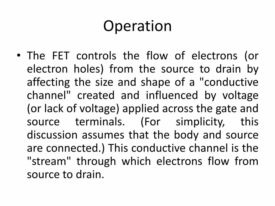
Operation
• The FET controls the flow of electrons (orelectron holes) from the source to drain byaffecting the size and shape of a "conductivechannel" created and influenced by voltage(or lack of voltage) applied across the gate andsource terminals. (For simplicity, thisdiscussion assumes that the body and sourceare connected.) This conductive channel is the"stream" through which electrons flow fromsource to drain.

n-channel• In an n-channel depletion-mode device, a negative gate-to-source
voltage causes a depletion region to expand in width and encroach onthe channel from the sides, narrowing the channel. If the depletionregion expands to completely close the channel, the resistance of thechannel from source to drain becomes large, and the FET is effectivelyturned off like a switch. This is called pinch-off, and the voltage atwhich it occurs is called the pinch-off voltage. Conversely, a positivegate-to-source voltage increases the channel size and allows electronsto flow easily.
• In an n-channel enhancement-mode device, a conductive channel doesnot exist naturally within the transistor, and a positive gate-to-sourcevoltage is necessary to create one. The positive voltage attracts free-floating electrons within the body towards the gate, forming aconductive channel. But first, enough electrons must be attracted nearthe gate to counter the dopant ions added to the body of the FET; thisforms a region with no mobile carriers called a depletion region, andthe voltage at which this occurs is referred to as the threshold voltageof the FET. Further gate-to-source voltage increase will attract evenmore electrons towards the gate which are able to create a conductivechannel from source to drain; this process is called inversion.


Applications
• As a FET chip occupies very small space ascompared to BJT chip, FETs are widely used inICs.
• FETs are used as voltage-variable resistors(WRs) in operational amplifiers (op-amps) andtone controls etc, for mixer operation on FMand TV receivers and in logic circuits.
• FETs are generally used in digital switchingcircuits though their operating speed is lower.


A transducer is a device that converts a signal in one form of energy toanother form of energy.Energy types include (but are not limited to) electrical,mechanical,electromagnetic (including light),chemical,acoustic andthermal energy.
A sensor is used to detect a parameter in one form and report it inanother form of energy, often an electrical signal. For example, apressure sensor might detect pressure (a mechanical form of energy)and convert it to electrical signal for display at a remote gauge.
An actuator accepts energy and produces movement (action). Theenergy supplied to an actuator might be electrical or mechanical(pneumatic, hydraulic, etc.). An electric motor and a loudspeaker areboth actuators, converting electrical energy into motion for differentpurposes.
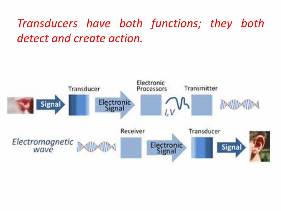
Transducers have both functions; they bothdetect and create action.

A transducer will have basically two main components. They are1. Sensing ElementThe physical quantity or its rate of change is sensed and responded to by this part ofthe transistor.2. Transduction ElementThe output of the sensing element is passed on to the transduction element. Thiselement is responsible for converting the non-electrical signal into its proportionalelectrical signal.There may be cases when the transduction element performs the action of bothtransduction and sensing. The best example of such a transducer is a thermocouple. Athermocouple is used to generate a voltage corresponding to the heat that is generatedat the junction of two dissimilar metals.

Selection of TransducerSelection of a transducer is one of the most important factors which help inobtaining accurate results. Some of the main parameters are given below.
• Selection depends on the physical quantity to be measured.• Depends on the best transducer principle for the given physical input.• Depends on the order of accuracy to be obtained.

Transducer Classification
Some of the common methods of classifying transducers are given below.
• Based on their application.• Based on the method of converting the non-electric signal into electric
signal.• Based on the output electrical quantity to be produced.• Based on the electrical phenomenon or parameter that may be changed
due to the whole process. Some of the most commonly electricalquantities in a transducer are resistance, capacitance, voltage, currentor inductance. Thus, during transduction, there may be changes inresistance, capacitance and induction, which in turn change the outputvoltage or current.
• Based on whether the transducer is active or passive.
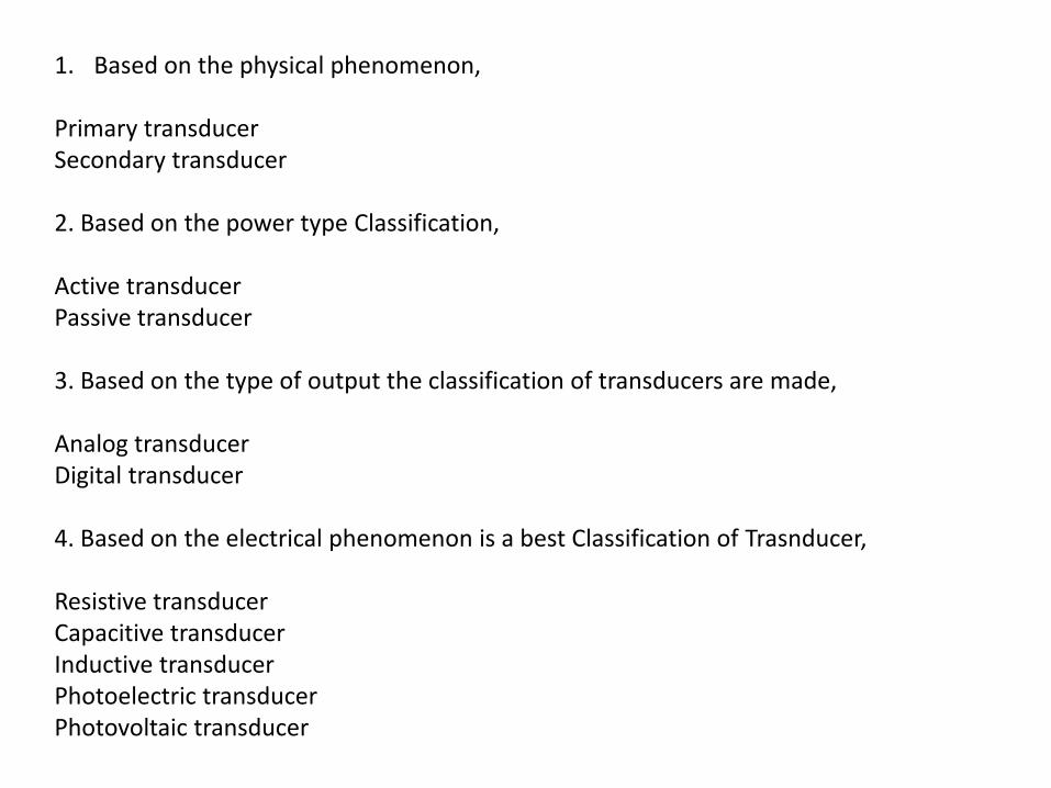
1. Based on the physical phenomenon,
Primary transducerSecondary transducer
2. Based on the power type Classification,
Active transducerPassive transducer
3. Based on the type of output the classification of transducers are made,
Analog transducerDigital transducer
4. Based on the electrical phenomenon is a best Classification of Trasnducer,
Resistive transducerCapacitive transducerInductive transducerPhotoelectric transducerPhotovoltaic transducer

5. Based on the non-electrical phenomenon Classification of transducer,
Linear displacementRotary displacement
6. Based on the transduction phenomenon,
TransducerInverse transducer.
Requirements of a good transducers
• Smaller in size and weight.• High sensitivity.• Ability to withstand environmental conditions.• Low cost.