FDOT Civil 3D Drainage Design & Resources · FDOT Civil 3D Drainage Design & Resources Randy...
18
FDOT Civil 3D Drainage Design & Resources Randy Roberts Engineering/CADD Systems Office Central Office – Tallahassee [email protected] Phone: 850-245-1631 All Presentations and Downloads will be available online A link will be emailed to all class registrants
-
Upload
phamkhuong -
Category
Documents
-
view
221 -
download
0
Transcript of FDOT Civil 3D Drainage Design & Resources · FDOT Civil 3D Drainage Design & Resources Randy...

FDOT Civil 3D Drainage Design & Resources
Randy Roberts
Engineering/CADD Systems Office
Central Office – Tallahassee
Phone: 850-245-1631
All Presentations and Downloads will be available online
A link will be emailed to all class registrants

Required Data for Pipe Networks
Surfaces – Existing & Proposed
Alignment – Road Centerline or Baseline
Modeled Corridor
FDOT Parts List (Truncated)

Editing the “FDOT Drainage” Parts List
It is imperative that you not rename the parts
list as you delete unneeded structure part
families. The name is needed for round
tripping purposes to and from SSA.
To delete parts right click on the FDOT
Drainage parts list and select Edit then
browse to the desired part family or part size
and right click and select delete.

Editing your Parts List
To add back a deleted part simply right click
on the Parts list and select Add part family.
Once a part family is added browse to the
bottom of the list and right click on the just
added part family and select Add part
size.

Laying out a Sample Drainage System
Launches the Pipe Creation Tools to start the
process of designing a drainage system
based on the FDOT Drainage parts list
From top to Bottom fill in the information such
as Network name, parts list, surface, etc.

Network Layout Tools Toolbar
Structure pull down allows you to select
various structures from the designated parts
list you are using. The pipe pull down
operates similar.
You can insert both Pipes and Structures or
each separately
Upslope/Down slope Toggle. Make sure you
are aware of which direction you are laying
out your system it will make editing easier
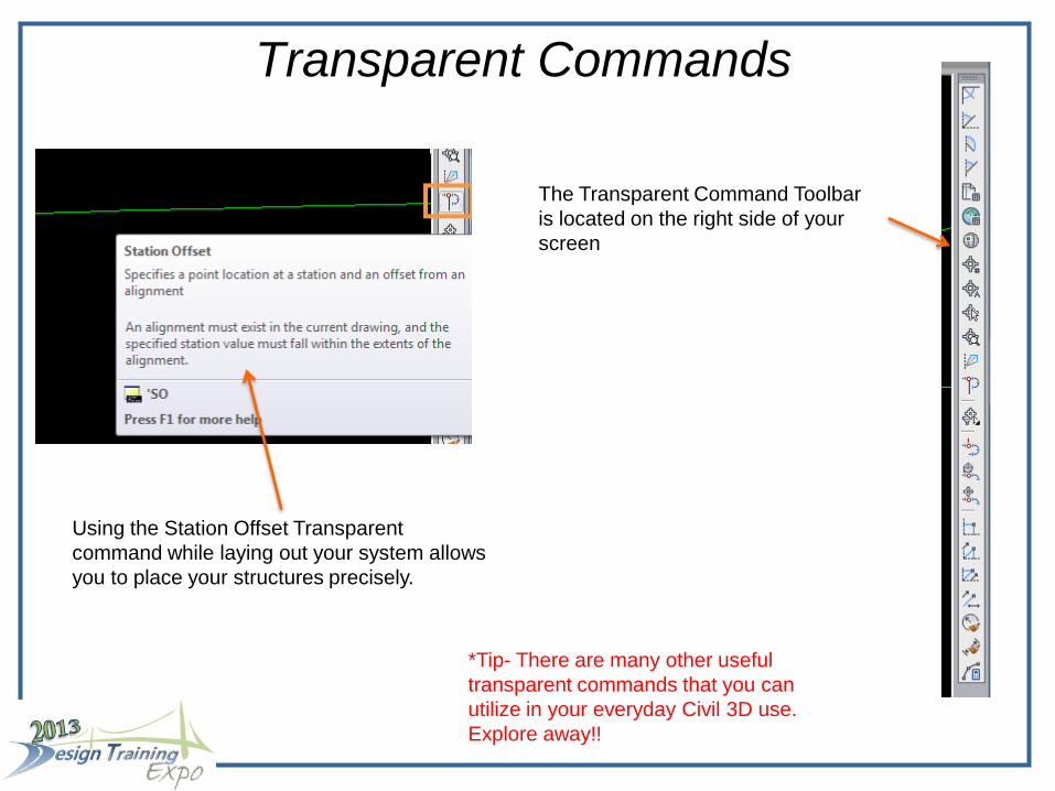
Transparent Commands
Using the Station Offset Transparent
command while laying out your system allows
you to place your structures precisely.
The Transparent Command Toolbar
is located on the right side of your
screen
*Tip- There are many other useful
transparent commands that you can
utilize in your everyday Civil 3D use.
Explore away!!

Editing your System
After system layout you can edit by grip
editing your structures to either move or rotate
them. As you move the structure around the
pipe stays attached.
When you select a part a ribbon
appears along the top for editing
purposes
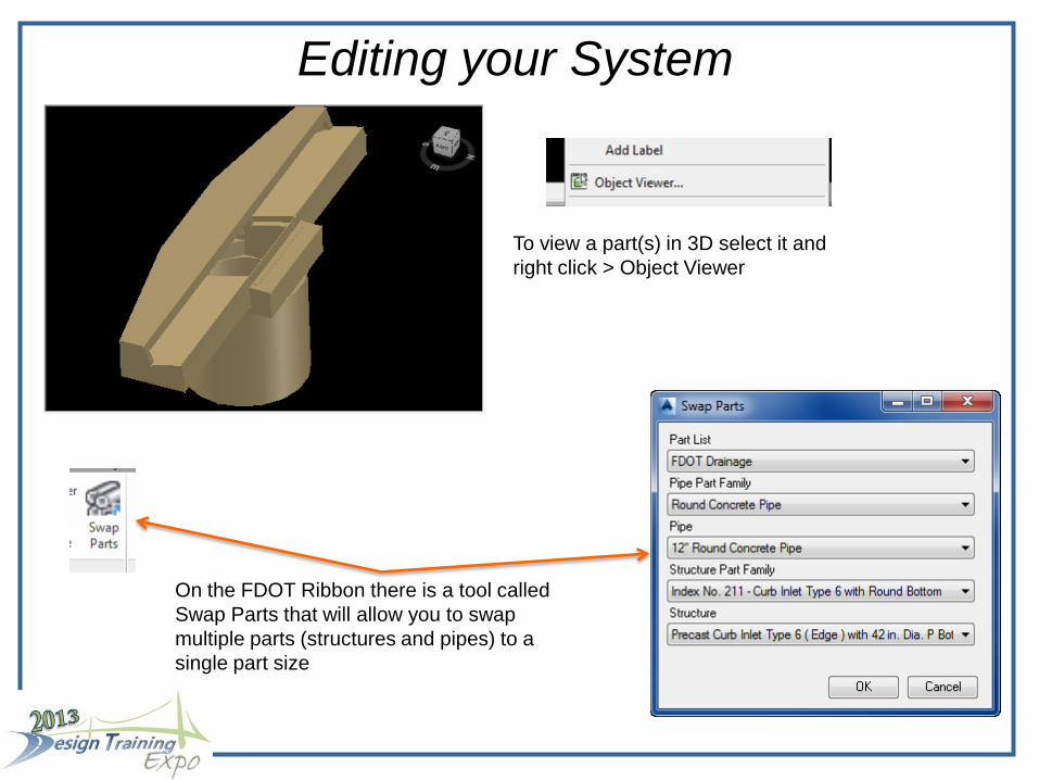
Editing your System
On the FDOT Ribbon there is a tool called
Swap Parts that will allow you to swap
multiple parts (structures and pipes) to a
single part size
To view a part(s) in 3D select it and
right click > Object Viewer

Sections and Profiles
A Profile view along the Alignment
A section view of our sample
drainage system
*Tip- If you create more drainage
systems or other utilities you can
project them to the section view
by selecting a section and on the
ribbon select “Sample More
Sources”

Grading a Detention Pond On the Home Ribbon select Grading > Grading Creation Tools
Grading Creation Toolbar
Select the FDOT Grading Criteria set
The FDOT Criteria set contains various
grading styles that you can use to grade with

Grading a Detention Pond
Select your grading style and select Create Grading
Pick the Feature Line and side to offset (Side of Grading)
If you do not have a feature line established a create feature line dialog box will appear after you select a polyline
If contours are not visible - right click on your Grading Group on prospector and select properties

Grading a Detention Pond
Select and right click on your pond > select object viewer
The bottom of your pond has a hole in it!
To fix this add a “Create Infill” to fill in
the bottom of your pond

Stage Storage Table
The final part of this equation is to create a Stage Storage Table for
storage calculations and to import into SSA for further analysis
First we have to extract objects from the surface, in this case
contour lines, this procedure will convert them to polylines with
elevations.
Select the contours manually by
using the select button

Stage Storage Table
Then we need to create a Boundary designating the top of pond
Make sure you clear the Non-destructive breakline box.
The pond surface with the surface contours hidden

Stage Storage Table 1. Located on the Analyze tab select Stage
Storage
2. Fill in the information from top to bottom, then click
Define Basin
3. Select Define to pick the
contours from the drawing

Stage Storage Table With the data located in
the dialog box you can
execute several options
located on the bottom.
The finished Stage Storage Table inserted in the drawing.
The next slide gives you some tips for working with SSA. In future classes we will
explore the relationship between FDOT projects and SSA

Tips for working with SSA
• Make sure you download and install the Civil 3D 32-bit object enabler even if you are
running a 64 bit system. SSA is a 32 bit application under the hood
• Unlike AutoCAD, SSA keeps you in a command until you press escape or click the
select element tool from the toolbar
• Don’t forget to save! There is no Auto-save
• Always work upstream to downstream
• There is no UNDO command in SSA, if you totally mess something up exit without
saving