FCC RF Test Report · Equipment WCDMA/LTE CPE Brand Name ZTE Model Name MF279 FCC ID SRQ-MF279 EUT...
42
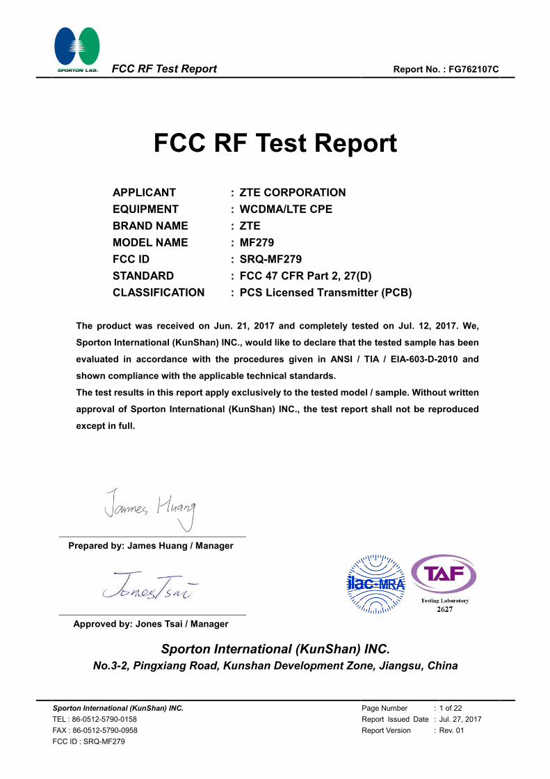
Sporton International (KunShan) INC. Page Number : 1 of 22 TEL : 86-0512-5790-0158 Report Issued Date : Jul. 27, 2017 FAX : 86-0512-5790-0958 Report Version : Rev. 01 FCC ID : SRQ-MF279 FCC RF Test Report Report No. : FG762107C FCC RF Test Report APPLICANT : ZTE CORPORATION EQUIPMENT : WCDMA/LTE CPE BRAND NAME : ZTE MODEL NAME : MF279 FCC ID : SRQ-MF279 STANDARD : FCC 47 CFR Part 2, 27(D) CLASSIFICATION : PCS Licensed Transmitter (PCB) The product was received on Jun. 21, 2017 and completely tested on Jul. 12, 2017. We, Sporton International (KunShan) INC., would like to declare that the tested sample has been evaluated in accordance with the procedures given in ANSI / TIA / EIA-603-D-2010 and shown compliance with the applicable technical standards. The test results in this report apply exclusively to the tested model / sample. Without written approval of Sporton International (KunShan) INC., the test report shall not be reproduced except in full. Prepared by: James Huang / Manager Approved by: Jones Tsai / Manager Sporton International (KunShan) INC. No.3-2, Pingxiang Road, Kunshan Development Zone, Jiangsu, China
Transcript of FCC RF Test Report · Equipment WCDMA/LTE CPE Brand Name ZTE Model Name MF279 FCC ID SRQ-MF279 EUT...
Sporton International (KunShan) INC. Page Number : 1 of 22
TEL : 86-0512-5790-0158 Report Issued Date : Jul. 27, 2017
FAX : 86-0512-5790-0958 Report Version : Rev. 01
FCC ID : SRQ-MF279
FCC RF Test Report Report No. : FG762107C
FCC RF Test Report
APPLICANT : ZTE CORPORATION
EQUIPMENT : WCDMA/LTE CPE
BRAND NAME : ZTE
MODEL NAME : MF279
FCC ID : SRQ-MF279
STANDARD : FCC 47 CFR Part 2, 27(D)
CLASSIFICATION : PCS Licensed Transmitter (PCB)
The product was received on Jun. 21, 2017 and completely tested on Jul. 12, 2017. We,
Sporton International (KunShan) INC., would like to declare that the tested sample has been
evaluated in accordance with the procedures given in ANSI / TIA / EIA-603-D-2010 and
shown compliance with the applicable technical standards.
The test results in this report apply exclusively to the tested model / sample. Without written
approval of Sporton International (KunShan) INC., the test report shall not be reproduced
except in full.
Prepared by: James Huang / Manager
Approved by: Jones Tsai / Manager
Sporton International (KunShan) INC. No.3-2, Pingxiang Road, Kunshan Development Zone, Jiangsu, China
Sporton International (KunShan) INC. Page Number : 2 of 22
TEL : 86-0512-5790-0158 Report Issued Date : Jul. 27, 2017
FAX : 86-0512-5790-0958 Report Version : Rev. 01
FCC ID : SRQ-MF279
FCC RF Test Report Report No. : FG762107C
TABLE OF CONTENTS REVISION HISTORY .......................................................................................................................................... 3
SUMMARY OF TEST RESULT ......................................................................................................................... 4
1 GENERAL DESCRIPTION .......................................................................................................................... 5
1.1 Applicant ............................................................................................................................................ 5 1.2 Manufacturer ...................................................................................................................................... 5 1.3 Product Feature of Equipment Under Test ........................................................................................ 5 1.4 Product Specification of Equipment Under Test ................................................................................ 6 1.5 Modification of EUT ........................................................................................................................... 6 1.6 Maximum Frequency Tolerance and Emission Designator ............................................................... 7 1.7 Testing Site ........................................................................................................................................ 7 1.8 Applied Standards ............................................................................................................................. 7
2 TEST CONFIGURATION OF EQUIPMENT UNDER TEST ........................................................................ 8
2.1 Test Mode .......................................................................................................................................... 8 2.2 Connection Diagram of Test System ................................................................................................. 9 2.3 Support Unit used in test configuration and system .......................................................................... 9 2.4 Measurement Results Explanation Example ................................................................................... 10 2.5 Frequency List of Low/Middle/High Channels ................................................................................. 10
3 CONDUCTED TEST ITEMS ...................................................................................................................... 11
3.1 Measuring Instruments .................................................................................................................... 11 3.2 Test Setup ....................................................................................................................................... 11 3.3 Test Result of Conducted Test ........................................................................................................ 11 3.4 Conducted Output Power Measurement ......................................................................................... 12 3.5 Peak-to-Average Ratio .................................................................................................................... 13 3.6 EIRP Power Density ........................................................................................................................ 14 3.7 Occupied Bandwidth ........................................................................................................................ 15 3.8 Conducted Band Edge Measurement ............................................................................................. 16 3.9 Conducted Spurious Emission Measurement ................................................................................. 17 3.10 Frequency Stability Measurement ................................................................................................... 18
4 RADIATED TEST ITEMS .......................................................................................................................... 19
4.1 Measuring Instruments .................................................................................................................... 19 4.2 Test Setup ....................................................................................................................................... 19 4.3 Test Result of Radiated Test ........................................................................................................... 19 4.4 Radiated Spurious Emission Measurement .................................................................................... 20
5 LIST OF MEASURING EQUIPMENT ........................................................................................................ 21
6 UNCERTAINTY OF EVALUATION ........................................................................................................... 22
APPENDIX A. TEST RESULTS OF CONDUCTED TEST
APPENDIX B. TEST RESULTS OF RADIATED TEST
APPENDIX C. TEST SETUP PHOTOGRAPHS
Sporton International (KunShan) INC. Page Number : 3 of 22
TEL : 86-0512-5790-0158 Report Issued Date : Jul. 27, 2017
FAX : 86-0512-5790-0958 Report Version : Rev. 01
FCC ID : SRQ-MF279
FCC RF Test Report Report No. : FG762107C
REVISION HISTORY
REPORT NO. VERSION DESCRIPTION ISSUED DATE
FG762107C Rev. 01 Initial issue of report Jul. 27, 2017
Sporton International (KunShan) INC. Page Number : 4 of 22
TEL : 86-0512-5790-0158 Report Issued Date : Jul. 27, 2017
FAX : 86-0512-5790-0958 Report Version : Rev. 01
FCC ID : SRQ-MF279
FCC RF Test Report Report No. : FG762107C
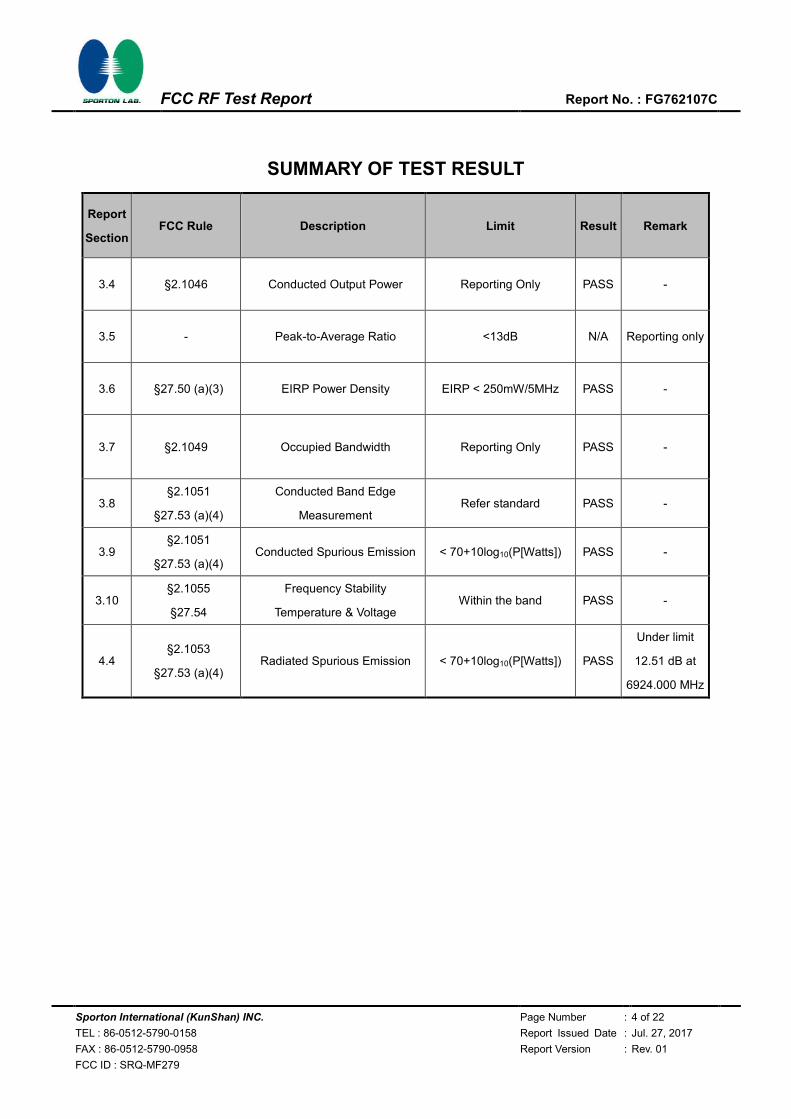
SUMMARY OF TEST RESULT
Report
Section FCC Rule Description Limit Result Remark
3.4 §2.1046 Conducted Output Power Reporting Only PASS -
3.5 - Peak-to-Average Ratio <13dB N/A Reporting only
3.6 §27.50 (a)(3) EIRP Power Density EIRP < 250mW/5MHz PASS -
3.7 §2.1049 Occupied Bandwidth Reporting Only PASS -
3.8 §2.1051
§27.53 (a)(4)
Conducted Band Edge
Measurement Refer standard PASS -
3.9 §2.1051
§27.53 (a)(4) Conducted Spurious Emission < 70+10log10(P[Watts]) PASS -
3.10 §2.1055
§27.54
Frequency Stability
Temperature & Voltage Within the band PASS -
4.4 §2.1053
§27.53 (a)(4) Radiated Spurious Emission < 70+10log10(P[Watts]) PASS
Under limit
12.51 dB at
6924.000 MHz

Sporton International (KunShan) INC. Page Number : 5 of 22
TEL : 86-0512-5790-0158 Report Issued Date : Jul. 27, 2017
FAX : 86-0512-5790-0958 Report Version : Rev. 01
FCC ID : SRQ-MF279
FCC RF Test Report Report No. : FG762107C
1 General Description
1.1 Applicant
ZTE CORPORATION
ZTE Plaza, Keji Road South, Hi-Tech, Industrial Park, Nanshan District, Shenzhen, Guangdong,
518057, P. R. China
1.2 Manufacturer
ZTE CORPORATION
ZTE Plaza, Keji Road South, Hi-Tech, Industrial Park, Nanshan District, Shenzhen, Guangdong,
518057, P. R. China
1.3 Product Feature of Equipment Under Test
Product Feature
Equipment WCDMA/LTE CPE
Brand Name ZTE
Model Name MF279
FCC ID SRQ-MF279
EUT supports Radios application
WCDMA/HSPA/HSPA+ (16QAM uplink is not supported)/LTE
WLAN2.4GHz 802.11b/g/n HT20/HT40
WLAN5GHz 802.11a/n HT20/HT40
WLAN5GHz 802.11ac VHT20/VHT40/VHT80
IMEI Code Conducted: 990008890000974
Radiation: 990008890001063
HW Version dqfA
SW Version EN_ZTE_MF279V0.0.0B02
EUT Stage Identical Prototype
Sporton International (KunShan) INC. Page Number : 6 of 22
TEL : 86-0512-5790-0158 Report Issued Date : Jul. 27, 2017
FAX : 86-0512-5790-0958 Report Version : Rev. 01
FCC ID : SRQ-MF279
FCC RF Test Report Report No. : FG762107C
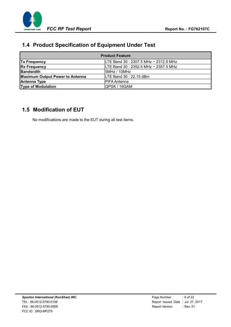
1.4 Product Specification of Equipment Under Test
Product Feature
Tx Frequency LTE Band 30 : 2307.5 MHz ~ 2312.5 MHz
Rx Frequency LTE Band 30 : 2352.5 MHz ~ 2357.5 MHz
Bandwidth 5MHz / 10MHz
Maximum Output Power to Antenna LTE Band 30 : 22.15 dBm
Antenna Type PIFA Antenna
Type of Modulation QPSK / 16QAM
1.5 Modification of EUT
No modifications are made to the EUT during all test items.
Sporton International (KunShan) INC. Page Number : 7 of 22
TEL : 86-0512-5790-0158 Report Issued Date : Jul. 27, 2017
FAX : 86-0512-5790-0958 Report Version : Rev. 01
FCC ID : SRQ-MF279
FCC RF Test Report Report No. : FG762107C
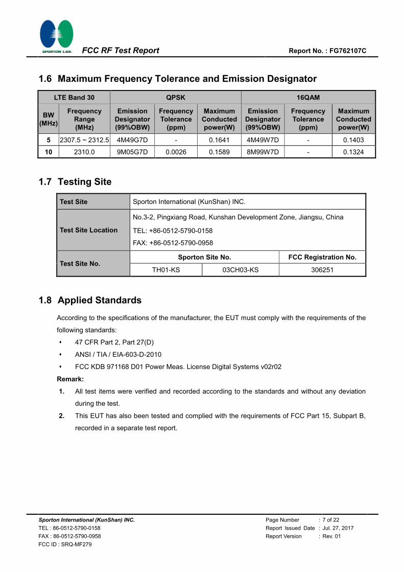
1.6 Maximum Frequency Tolerance and Emission Designator
LTE Band 30 QPSK 16QAM
BW (MHz)
Frequency Range (MHz)
Emission Designator (99%OBW)
Frequency Tolerance
(ppm)
Maximum Conducted power(W)
Emission Designator (99%OBW)
Frequency Tolerance
(ppm)
Maximum Conducted power(W)
5 2307.5 ~ 2312.5 4M49G7D - 0.1641 4M49W7D - 0.1403
10 2310.0 9M05G7D 0.0026 0.1589 8M99W7D - 0.1324
1.7 Testing Site
Test Site Sporton International (KunShan) INC.
Test Site Location
No.3-2, Pingxiang Road, Kunshan Development Zone, Jiangsu, China
TEL: +86-0512-5790-0158
FAX: +86-0512-5790-0958
Test Site No. Sporton Site No. FCC Registration No.
TH01-KS 03CH03-KS 306251
1.8 Applied Standards
According to the specifications of the manufacturer, the EUT must comply with the requirements of the
following standards:
47 CFR Part 2, Part 27(D)
ANSI / TIA / EIA-603-D-2010
FCC KDB 971168 D01 Power Meas. License Digital Systems v02r02
Remark:
1. All test items were verified and recorded according to the standards and without any deviation
during the test.
2. This EUT has also been tested and complied with the requirements of FCC Part 15, Subpart B,
recorded in a separate test report.
Sporton International (KunShan) INC. Page Number : 8 of 22
TEL : 86-0512-5790-0158 Report Issued Date : Jul. 27, 2017
FAX : 86-0512-5790-0958 Report Version : Rev. 01
FCC ID : SRQ-MF279
FCC RF Test Report Report No. : FG762107C
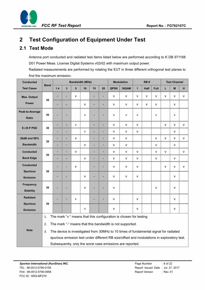
2 Test Configuration of Equipment Under Test
2.1 Test Mode
Antenna port conducted and radiated test items listed below are performed according to K DB 971168
D01 Power Meas. License Digital Systems v02r02 with maximum output power.
Radiated measurements are performed by rotating the EUT in three different orthogonal test planes to
find the maximum emission.
Conducted
Test Cases Band
Bandwidth (MHz) Modulation RB # Test Channel
1.4 3 5 10 15 20 QPSK 16QAM 1 Half Full L M H
Max. Output
Power 30
- - v - - v v v v v v v v
- - v - - v v v v v v
Peak-to-Average
Ratio 30 - - v - - v v v v v
E.I.R.P PSD 30 - - v - - v v v v v v
- - v - - v v v v
26dB and 99%
Bandwidth 30
- - v - - v v v v v v
- - v - - v v v v
Conducted
Band Edge 30
- - v - - v v v v v v
- - v - - v v v v v
Conducted
Spurious
Emission
30
- - v - - v v v v v v
- - v - - v v v v
Frequency
Stability 30 - - v - - v v v
Radiated
Spurious
Emission
30
- - v - - v v v
v v v v
Note
1. The mark “v “ means that this configuration is chosen for testing
2. The mark “-“ means that this bandwidth is not supported.
3. The device is investigated from 30MHz to 10 times of fundamental signal for radiated
spurious emission test under different RB size/offset and modulations in exploratory test.
Subsequently, only the worst case emissions are reported.
Sporton International (KunShan) INC. Page Number : 9 of 22
TEL : 86-0512-5790-0158 Report Issued Date : Jul. 27, 2017
FAX : 86-0512-5790-0958 Report Version : Rev. 01
FCC ID : SRQ-MF279
FCC RF Test Report Report No. : FG762107C
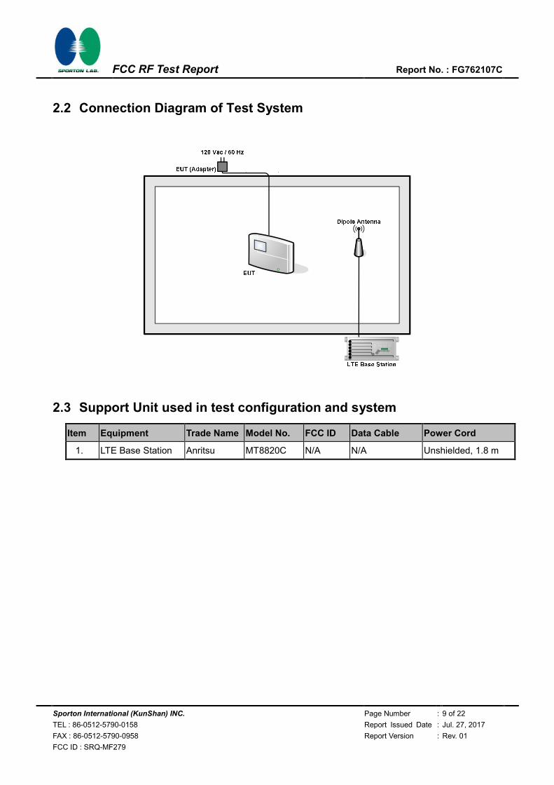
2.2 Connection Diagram of Test System
2.3 Support Unit used in test configuration and system
Item Equipment Trade Name Model No. FCC ID Data Cable Power Cord
1. LTE Base Station Anritsu MT8820C N/A N/A Unshielded, 1.8 m

Sporton International (KunShan) INC. Page Number : 10 of 22
TEL : 86-0512-5790-0158 Report Issued Date : Jul. 27, 2017
FAX : 86-0512-5790-0958 Report Version : Rev. 01
FCC ID : SRQ-MF279
FCC RF Test Report Report No. : FG762107C
2.4 Measurement Results Explanation Example
For all conducted test items:
The offset level is set in the spectrum analyzer to compensate the RF cable loss between EUT
conducted output port and spectrum analyzer. With the offset compensation, the spectrum analyzer
reading level is exactly the EUT RF output level.
The spectrum analyzer offset is derived from RF cable loss.
Offset = RF cable loss.
Following shows an offset computation example with cable loss 4.5 dB.
Example :
Offset(dB) = RF cable loss(dB).
= 4.5 (dB)
2.5 Frequency List of Low/Middle/High Channels
LTE Band 30 Channel and Frequency List
BW [MHz] Channel/Frequency(MHz) Lowest Middle Highest
10 Channel - 27710 -
Frequency - 2310 -
5 Channel 27685 27710 27735
Frequency 2307.5 2310 2312.5
Sporton International (KunShan) INC. Page Number : 11 of 22
TEL : 86-0512-5790-0158 Report Issued Date : Jul. 27, 2017
FAX : 86-0512-5790-0958 Report Version : Rev. 01
FCC ID : SRQ-MF279
FCC RF Test Report Report No. : FG762107C
3 Conducted Test Items
3.1 Measuring Instruments
See list of measuring instruments of this test report.
3.2 Test Setup
3.2.1 Conducted Output Power
3.2.2 Peak-to-Average Ratio, Occupied / 26dB Bandwidth ,Band-Edge and Conducted
Spurious Emission
3.2.3 Frequency Stability
3.3 Test Result of Conducted Test
Please refer to Appendix A.
Sporton International (KunShan) INC. Page Number : 12 of 22
TEL : 86-0512-5790-0158 Report Issued Date : Jul. 27, 2017
FAX : 86-0512-5790-0958 Report Version : Rev. 01
FCC ID : SRQ-MF279
FCC RF Test Report Report No. : FG762107C
3.4 Conducted Output Power Measurement
3.4.1 Description of the Conducted Output Power Measurement
A base station simulator was used to establish communication with the EUT. Its parameters were set
to transmit the maximum power on the EUT. The measured power in the radio frequency on the
transmitter output terminals shall be reported.
3.4.2 Test Procedures
1. The transmitter output port was connected to base station.
2. Set EUT at maximum power through base station.
3. Select lowest, middle, and highest channels for each band and different modulation.
Sporton International (KunShan) INC. Page Number : 13 of 22
TEL : 86-0512-5790-0158 Report Issued Date : Jul. 27, 2017
FAX : 86-0512-5790-0958 Report Version : Rev. 01
FCC ID : SRQ-MF279
FCC RF Test Report Report No. : FG762107C
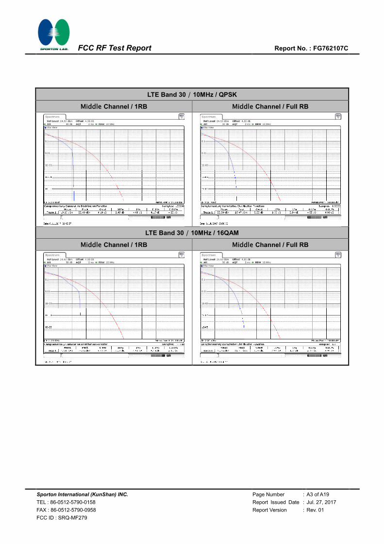
3.5 Peak-to-Average Ratio
3.5.1 Description of the PAR Measurement
Power Complementary Cumulative Distribution Function (CCDF) curves provide a means for
characterizing the power peaks of a digitally modulated signal on a statistical basis. A CCDF curve
depicts the probability of the peak signal amplitude exceeding the average power level. Most
contemporary measurement instrumentation include the capability to produce CCDF curves for an
input signal provided that the instrument’s resolution bandwidth can be set wide enough to
accommodate the entire input signal bandwidth. In measuring transmissions in this band using an
average power technique, the peak-to-average ratio (PAR) of the transmission may not exceed 13
dB.
3.5.2 Test Procedures
1. The testing follows FCC KDB 971168 v02r02 Section 5.7.1.
2. The EUT was connected to spectrum and system simulator via a power divider.
3. Set the CCDF (Complementary Cumulative Distribution Function) option in spectrum analyzer.
4. The highest RF powers were measured and recorded the maximum PAPR level associated with
a probability of 0.1 %.
5. Record the deviation as Peak to Average Ratio.
Sporton International (KunShan) INC. Page Number : 14 of 22
TEL : 86-0512-5790-0158 Report Issued Date : Jul. 27, 2017
FAX : 86-0512-5790-0958 Report Version : Rev. 01
FCC ID : SRQ-MF279
FCC RF Test Report Report No. : FG762107C
3.6 EIRP Power Density
3.6.1 Description of EIRP Power Density
For mobile and portable stations transmitting in the 2305-2315 MHz band or the 2350-2360 MHz
band, the average EIRP must not exceed 50 milliwatts within any 1 megahertz of authorized
bandwidth, except that for mobile and portable stations compliant with 3GPP LTE standards or
another advanced mobile broadband protocol that avoids concentrating energy at the edge of the
operating band the average EIRP must not exceed 250 milliwatts within any 5 megahertz of
authorized bandwidth but may exceed 50 milliwatts within any 1 megahertz of authorized bandwidth.
For mobile and portable stations using time division duplexing (TDD) technology, the duty cycle
must not exceed 38 percent in the 2305-2315 MHz and 2350-2360 MHz bands. Mobile and portable
stations using FDD technology are restricted to transmitting in the 2305-2315 MHz band. Power
averaging shall not include intervals in which the transmitter is off.
3.6.2 Test Procedures
1. Set instrument center frequency to OBW center frequency.
2. Set span to at least 1.5 times the OBW.
3. Set the RBW to the specified reference bandwidth (often 1 MHz).
4. Set VBW ≥ 3 × RBW.
5. Detector = RMS (power averaging).
6. Ensure that the number of measurement points in the sweep ≥ 2 × span/RBW.
7. Sweep time = auto couple.
8. Employ trace averaging (RMS) mode over a minimum of 100 traces.
9. Use the peak marker function to determine the maximum amplitude level within the reference
bandwidth (PSD).
Sporton International (KunShan) INC. Page Number : 15 of 22
TEL : 86-0512-5790-0158 Report Issued Date : Jul. 27, 2017
FAX : 86-0512-5790-0958 Report Version : Rev. 01
FCC ID : SRQ-MF279
FCC RF Test Report Report No. : FG762107C
3.7 Occupied Bandwidth
3.7.1 Description of Occupied Bandwidth Measurement
The occupied bandwidth is the width of a frequency band such that, below the lower and above the
upper frequency limits, the mean powers emitted are each equal to a specified percentage 0.5% of
the total mean transmitted power.
The 26dB occupied bandwidth is the width of a frequency band such that, below the lower and above
the upper frequency limits, the mean powers emitted are each equal 26 dB.
The 26 dB emission bandwidth(EBW) is defined as the frequency range between two points, one
above and one below the carrier frequency, at which the spectral density of the emission is
attenuated 26 dB below the maximum in-band spectral density of the modulated signal. Spectral
density (power per unit bandwidth) is to be measured with a detector of resolution bandwidth equal to
approximately 1.0% of the emission bandwidth.
3.7.2 Test Procedures
1. The EUT was connected to Spectrum Analyzer and Base Station via power divider.
2. The 26dB and 99% occupied bandwidth (BW) of the middle channel for the highest RF powers
with full RB sizes were measured.
Sporton International (KunShan) INC. Page Number : 16 of 22
TEL : 86-0512-5790-0158 Report Issued Date : Jul. 27, 2017
FAX : 86-0512-5790-0958 Report Version : Rev. 01
FCC ID : SRQ-MF279
FCC RF Test Report Report No. : FG762107C
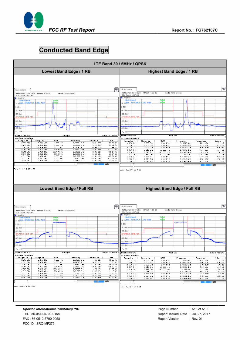
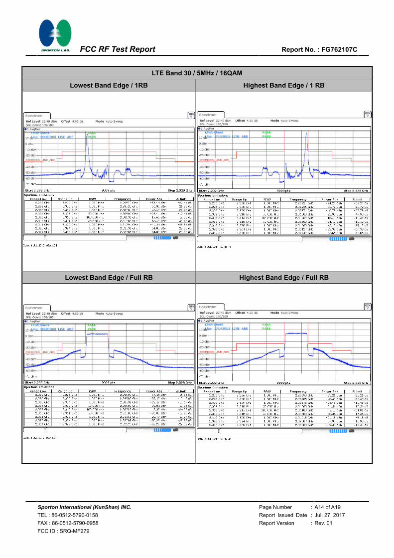
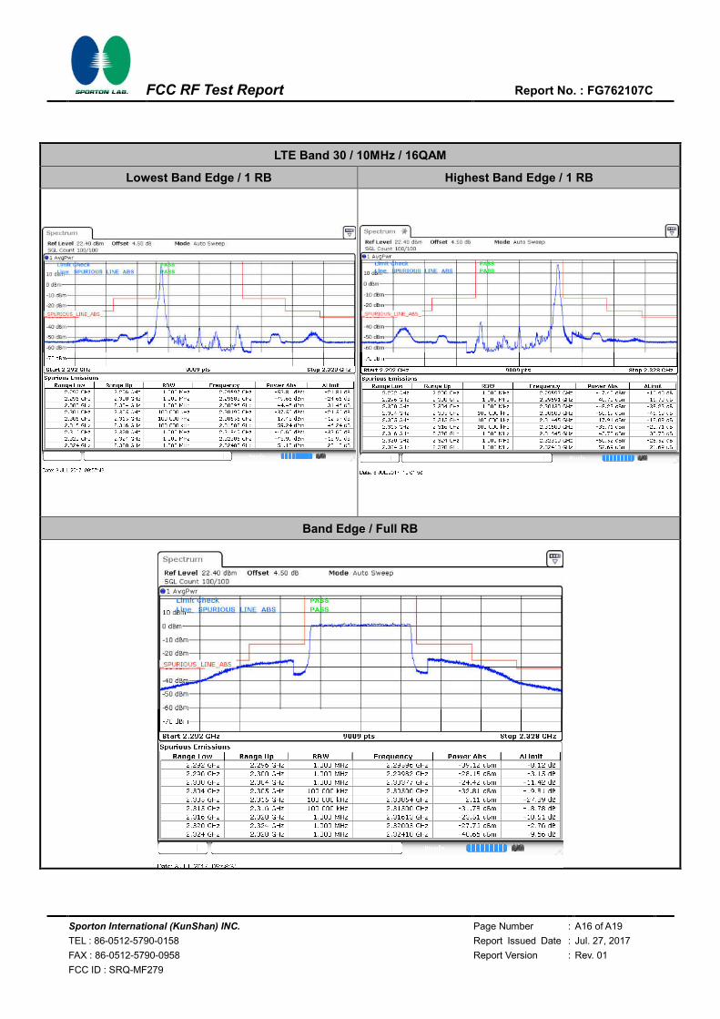
3.8 Conducted Band Edge Measurement
3.8.1 Description of Conducted Band Edge Measurement
27.53 (a)(4)
For mobile and portable stations operating in the 2305-2315 MHz and 2350-2360 MHz bands:
(i) By a factor of not less than: 43 + 10 log (P) dB on all frequencies between 2305 and 2320 MHz and
on all frequencies between 2345 and 2360 MHz that are outside the licensed band(s) of operation,
not less than 55 + 10 log (P) dB on all frequencies between 2320 and 2324 MHz and on all
frequencies between 2341 and 2345 MHz, not less than 61 + 10 log (P) dB on all frequencies
between 2324 and 2328 MHz and on all frequencies between 2337 and 2341 MHz, and not less than
67 + 10 log (P) dB on all frequencies between 2328 and 2337 MHz;
(ii) By a factor of not less than 43 + 10 log (P) dB on all frequencies between 2300 and 2305 MHz, 55
+ 10 log (P) dB on all frequencies between 2296 and 2300 MHz, 61 + 10 log (P) dB on all frequencies
between 2292 and 2296 MHz, 67 + 10 log (P) dB on all frequencies between 2288 and 2292 MHz,
and 70 + 10 log (P) dB below 2288 MHz;
(iii) By a factor of not less than 43 + 10 log (P) dB on all frequencies between 2360 and 2365 MHz,
and not less than 70 + 10 log (P) dB above 2365 MHz.
3.8.2 Test Procedures
1. The EUT was connected to Spectrum Analyzer and Base Station via power divider.
2. The band edges of low and high channels were measured with RBW ≥ 1% EBW set in Spectrum
Analyzer, while the EUT was transmitting under maximum power.
3. The RF fundamental frequency should be excluded against the limit line in the operating
frequency band.
4. The limit line is derived from 43 + 10log(P)dB below the transmitter power P(Watts)
= P(W)- [43 + 10log(P)] (dB) = [30 + 10log(P)] (dBm) - [43 + 10log(P)] (dB) = -13dBm.

Sporton International (KunShan) INC. Page Number : 17 of 22
TEL : 86-0512-5790-0158 Report Issued Date : Jul. 27, 2017
FAX : 86-0512-5790-0958 Report Version : Rev. 01
FCC ID : SRQ-MF279
FCC RF Test Report Report No. : FG762107C
3.9 Conducted Spurious Emission Measurement
3.9.1 Description of Conducted Spurious Emission Measurement
The power of any emission outside of the authorized operating frequency ranges must be lower than
the transmitter power (P) by a factor of at least 70 + 10 log (P) dB.
It is measured by means of a calibrated spectrum analyzer and scanned from 30MHz up to a
frequency including its 10th harmonic.
3.9.2 Test Procedures
1. The EUT was connected to spectrum analyzer and base station via power divider.
2. The RF output of EUT was connected to the spectrum analyzer by RF cable and attenuator.
The path loss was compensated to the results for each measurement.
3. The middle channel for the highest RF power within the transmitting frequency was measured.
4. The conducted spurious emission for the whole frequency range was taken.
5. Make the measurement with the spectrum analyzer's RBW = 1MHz, VBW = 3MHz, taking the
record of maximum spurious emission.
6. The RF fundamental frequency should be excluded against the limit line in the operating
frequency band.
7. The limit line is derived from 70 + 10log(P)dB below the transmitter power P(Watts)
= P(W)- [70 + 10log(P)] (dB)
= [30 + 10log(P)] (dBm) - [70 + 10log(P)] (dB)
= -40dBm.
Sporton International (KunShan) INC. Page Number : 18 of 22
TEL : 86-0512-5790-0158 Report Issued Date : Jul. 27, 2017
FAX : 86-0512-5790-0958 Report Version : Rev. 01
FCC ID : SRQ-MF279
FCC RF Test Report Report No. : FG762107C
3.10 Frequency Stability Measurement
3.10.1 Description of Frequency Stability Measurement
The frequency stability shall be measured by variation of ambient temperature and variation of
primary supply voltage to ensure that the fundamental emission stays within the authorized frequency
block. The frequency stability of the transmitter shall be maintained within ±0.00025% (±2.5ppm) of
the center frequency.
3.10.2 Test Procedures for Temperature Variation
1. The EUT was set up in the thermal chamber and connected with the base station.
2. With power OFF, the temperature was decreased to -30°C and the EUT was stabilized before
testing. Power was applied and the maximum change in frequency was recorded within one
minute.
3. With power OFF, the temperature was raised in 10°C step up to 50°C. The EUT was stabilized
at each step for at least half an hour. Power was applied and the maximum frequency change
was recorded within one minute.
3.10.3 Test Procedures for Voltage Variation
1. The EUT was placed in a temperature chamber at 25±5° C and connected with the base
station.
2. The power supply voltage to the EUT was varied from 85% to 115% of the nominal value
measured at the input to the EUT.
3. The variation in frequency was measured for the worst case.
Sporton International (KunShan) INC. Page Number : 19 of 22
TEL : 86-0512-5790-0158 Report Issued Date : Jul. 27, 2017
FAX : 86-0512-5790-0958 Report Version : Rev. 01
FCC ID : SRQ-MF279
FCC RF Test Report Report No. : FG762107C
4 Radiated Test Items
4.1 Measuring Instruments
See list of measuring instruments of this test report.
4.2 Test Setup
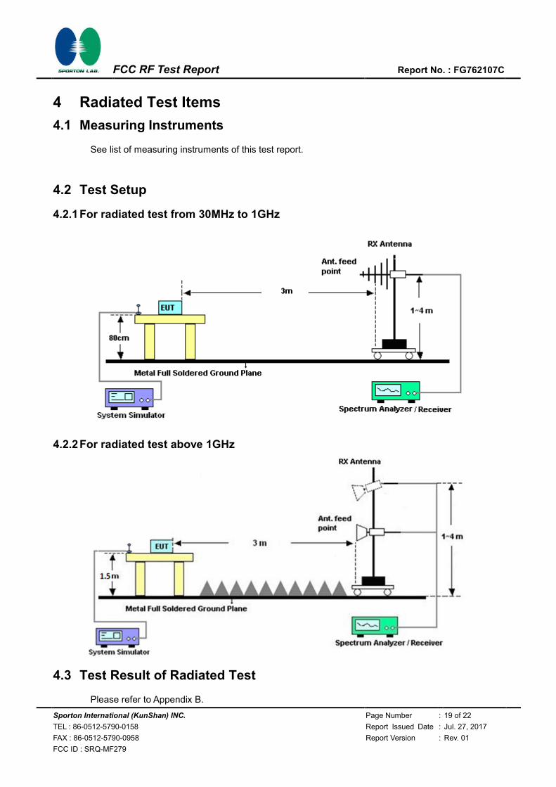
4.2.1 For radiated test from 30MHz to 1GHz
4.2.2 For radiated test above 1GHz
4.3 Test Result of Radiated Test
Please refer to Appendix B.
Sporton International (KunShan) INC. Page Number : 20 of 22
TEL : 86-0512-5790-0158 Report Issued Date : Jul. 27, 2017
FAX : 86-0512-5790-0958 Report Version : Rev. 01
FCC ID : SRQ-MF279
FCC RF Test Report Report No. : FG762107C
4.4 Radiated Spurious Emission Measurement
4.4.1 Description of Radiated Spurious Emission
The radiated spurious emission was measured by substitution method according to ANSI / TIA /
EIA-603-D-2010.
The power of any emission outside of the authorized operating frequency ranges must be attenuated
below the transmitter power (P) by a factor of at least 70 + 10 log (P) dB.
4.4.2 Test Procedures
1. The EUT was placed on a turntable with 0.8 meter for frequency below 1GHz and 1.5 meter for
frequency above 1GHz respectively above ground.
2. The EUT was set 3 meters from the receiving antenna, which was mounted on the antenna
tower.
3. The table was rotated 360 degrees to determine the position of the highest spurious emission.
4. The height of the receiving antenna is varied between one meter and four meters to search the
maximum spurious emission for both horizontal and vertical polarizations.
5. Make the measurement with the spectrum analyzer's RBW = 1MHz, VBW = 3MHz, Sweep =
500ms, Taking the record of maximum spurious emission.
6. A horn antenna was substituted in place of the EUT and was driven by a signal generator.
7. Tune the output power of signal generator to the same emission level with EUT maximum
spurious emission.
8. Taking the record of output power at antenna port.
9. Repeat step 7 to step 8 for another polarization.
10. The RF fundamental frequency should be excluded against the limit line in the operating
frequency band.
The limit line is derived from 70 + 10log(P)dB below the transmitter power P(Watts)
= P(W)- [70 + 10log(P)] (dB)
= [30 + 10log(P)] (dBm) - [70 + 10log(P)] (dB)
= -40dBm.
11. EIRP (dBm) = S.G. Power – Tx Cable Loss + Tx Antenna Gain
Sporton International (KunShan) INC. Page Number : 21 of 22
TEL : 86-0512-5790-0158 Report Issued Date : Jul. 27, 2017
FAX : 86-0512-5790-0958 Report Version : Rev. 01
FCC ID : SRQ-MF279
FCC RF Test Report Report No. : FG762107C
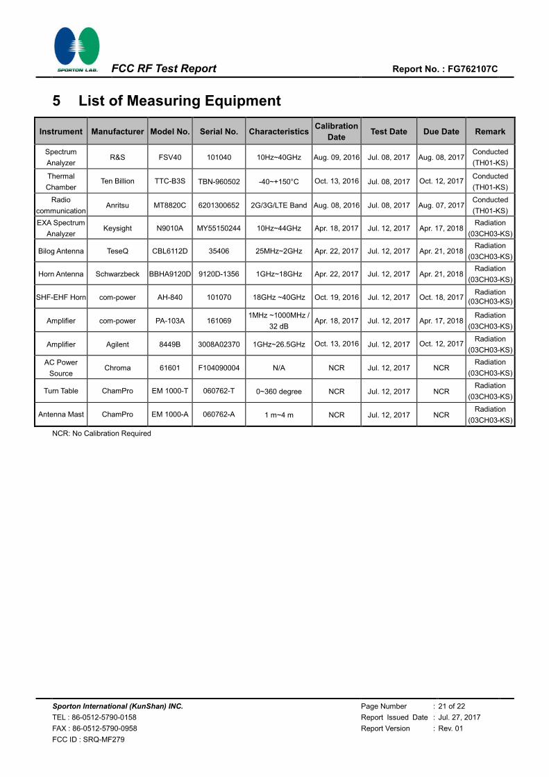
5 List of Measuring Equipment
Instrument Manufacturer Model No. Serial No. Characteristics Calibration
Date Test Date Due Date Remark
Spectrum
Analyzer R&S FSV40 101040 10Hz~40GHz Aug. 09, 2016 Jul. 08, 2017 Aug. 08, 2017
Conducted
(TH01-KS)
Thermal
Chamber Ten Billion TTC-B3S TBN-960502 -40~+150°C Oct. 13, 2016 Jul. 08, 2017 Oct. 12, 2017
Conducted
(TH01-KS)
Radio
communication Anritsu MT8820C 6201300652 2G/3G/LTE Band Aug. 08, 2016 Jul. 08, 2017 Aug. 07, 2017
Conducted
(TH01-KS)
EXA Spectrum
Analyzer Keysight N9010A MY55150244 10Hz~44GHz Apr. 18, 2017 Jul. 12, 2017 Apr. 17, 2018
Radiation
(03CH03-KS)
Bilog Antenna TeseQ CBL6112D 35406 25MHz~2GHz Apr. 22, 2017 Jul. 12, 2017 Apr. 21, 2018 Radiation
(03CH03-KS)
Horn Antenna Schwarzbeck BBHA9120D 9120D-1356 1GHz~18GHz Apr. 22, 2017 Jul. 12, 2017 Apr. 21, 2018 Radiation
(03CH03-KS)
SHF-EHF Horn com-power AH-840 101070 18GHz ~40GHz Oct. 19, 2016 Jul. 12, 2017 Oct. 18, 2017 Radiation
(03CH03-KS)
Amplifier com-power PA-103A 161069 1MHz ~1000MHz /
32 dB Apr. 18, 2017 Jul. 12, 2017 Apr. 17, 2018
Radiation
(03CH03-KS)
Amplifier Agilent 8449B 3008A02370 1GHz~26.5GHz Oct. 13, 2016 Jul. 12, 2017 Oct. 12, 2017 Radiation
(03CH03-KS)
AC Power
Source Chroma 61601 F104090004 N/A NCR Jul. 12, 2017 NCR
Radiation
(03CH03-KS)
Turn Table ChamPro EM 1000-T 060762-T 0~360 degree NCR Jul. 12, 2017 NCR Radiation
(03CH03-KS)
Antenna Mast ChamPro EM 1000-A 060762-A 1 m~4 m NCR Jul. 12, 2017 NCR Radiation
(03CH03-KS)
NCR: No Calibration Required
Sporton International (KunShan) INC. Page Number : 22 of 22
TEL : 86-0512-5790-0158 Report Issued Date : Jul. 27, 2017
FAX : 86-0512-5790-0958 Report Version : Rev. 01
FCC ID : SRQ-MF279
FCC RF Test Report Report No. : FG762107C
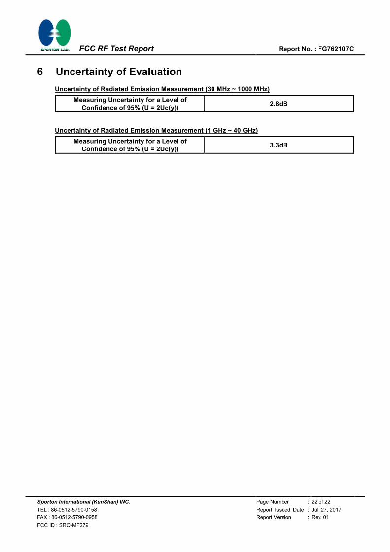
6 Uncertainty of Evaluation
Uncertainty of Radiated Emission Measurement (30 MHz ~ 1000 MHz)
Measuring Uncertainty for a Level of Confidence of 95% (U = 2Uc(y))
2.8dB
Uncertainty of Radiated Emission Measurement (1 GHz ~ 40 GHz)
Measuring Uncertainty for a Level of Confidence of 95% (U = 2Uc(y))
3.3dB
Sporton International (KunShan) INC. Page Number : A1 of A19
TEL : 86-0512-5790-0158 Report Issued Date : Jul. 27, 2017
FAX : 86-0512-5790-0958 Report Version : Rev. 01
FCC ID : SRQ-MF279
FCC RF Test Report Report No. : FG762107C
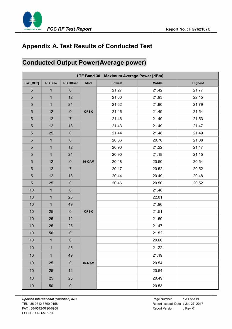
Appendix A. Test Results of Conducted Test
Conducted Output Power(Average power)
LTE Band 30 Maximum Average Power [dBm]
BW [MHz] RB Size RB Offset Mod Lowest Middle Highest
5 1 0
QPSK
21.27 21.42 21.77
5 1 12 21.60 21.93 22.15
5 1 24 21.62 21.90 21.79
5 12 0 21.46 21.49 21.54
5 12 7 21.46 21.49 21.53
5 12 13 21.43 21.49 21.47
5 25 0 21.44 21.48 21.49
5 1 0
16-QAM
20.56 20.70 21.08
5 1 12 20.90 21.22 21.47
5 1 24 20.90 21.18 21.15
5 12 0 20.48 20.50 20.54
5 12 7 20.47 20.52 20.52
5 12 13 20.44 20.49 20.48
5 25 0 20.46 20.50 20.52
10 1 0
QPSK
21.48
10 1 25 22.01
10 1 49 21.96
10 25 0 21.51
10 25 12 21.50
10 25 25 21.47
10 50 0 21.52
10 1 0
16-QAM
20.60
10 1 25 21.22
10 1 49 21.19
10 25 0 20.54
10 25 12 20.54
10 25 25 20.49
10 50 0 20.53
Sporton International (KunShan) INC. Page Number : A2 of A19
TEL : 86-0512-5790-0158 Report Issued Date : Jul. 27, 2017
FAX : 86-0512-5790-0958 Report Version : Rev. 01
FCC ID : SRQ-MF279
FCC RF Test Report Report No. : FG762107C
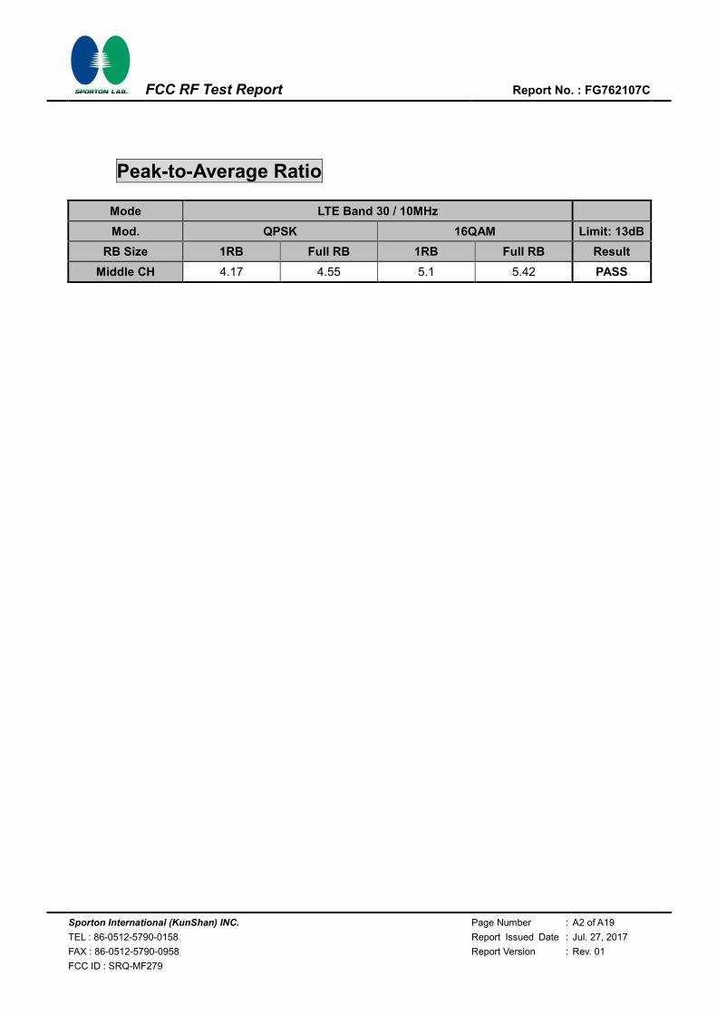
Peak-to-Average Ratio
Mode LTE Band 30 / 10MHz
Mod. QPSK 16QAM Limit: 13dB
RB Size 1RB Full RB 1RB Full RB Result
Middle CH 4.17 4.55 5.1 5.42 PASS
Sporton International (KunShan) INC. Page Number : A3 of A19
TEL : 86-0512-5790-0158 Report Issued Date : Jul. 27, 2017
FAX : 86-0512-5790-0958 Report Version : Rev. 01
FCC ID : SRQ-MF279
FCC RF Test Report Report No. : FG762107C
LTE Band 30 / 10MHz / QPSK
Middle Channel / 1RB Middle Channel / Full RB
LTE Band 30 / 10MHz / 16QAM
Middle Channel / 1RB Middle Channel / Full RB
Sporton International (KunShan) INC. Page Number : A4 of A19
TEL : 86-0512-5790-0158 Report Issued Date : Jul. 27, 2017
FAX : 86-0512-5790-0958 Report Version : Rev. 01
FCC ID : SRQ-MF279
FCC RF Test Report Report No. : FG762107C
EIRP Power Density
Mode LTE Band 30 : Conducted Power Density (dBm/5MHz)
BW 1.4MHz 3MHz 5MHz 10MHz 15MHz 20MHz
Mod. QPSK 16QAM QPSK 16QAM QPSK 16QAM QPSK 16QAM QPSK 16QAM QPSK 16QAM
Lowest CH 21.37 20.89
Middle CH 21.30 20.63 21.35 20.99
Highest CH 21.67 21.16
Mode LTE Band 30 : EIRP Power Density (dBm/5MHz)
BW 1.4MHz 3MHz 5MHz 10MHz 15MHz 20MHz
Mod. QPSK 16QAM QPSK 16QAM QPSK 16QAM QPSK 16QAM QPSK 16QAM QPSK 16QAM
Lowest CH 22.87 22.39
Middle CH 22.80 22.13 22.85 22.49
Highest CH 23.17 22.66
Antenna Gain 1.5dBi
Limit 250mW / 5MHz = 24dBm / 5MHz
Result Pass
Sporton International (KunShan) INC. Page Number : A5 of A19
TEL : 86-0512-5790-0158 Report Issued Date : Jul. 27, 2017
FAX : 86-0512-5790-0958 Report Version : Rev. 01
FCC ID : SRQ-MF279
FCC RF Test Report Report No. : FG762107C
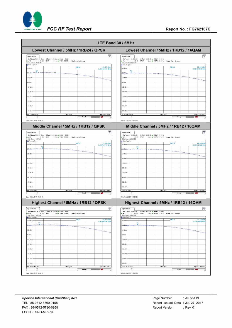
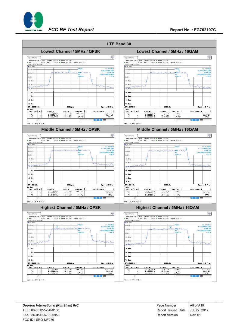
LTE Band 30 / 5MHz
Lowest Channel / 5MHz / 1RB24 / QPSK Lowest Channel / 5MHz / 1RB12 / 16QAM
Middle Channel / 5MHz / 1RB12 / QPSK Middle Channel / 5MHz / 1RB12 / 16QAM
Highest Channel / 5MHz / 1RB12 / QPSK Highest Channel / 5MHz / 1RB12 / 16QAM
Sporton International (KunShan) INC. Page Number : A6 of A19
TEL : 86-0512-5790-0158 Report Issued Date : Jul. 27, 2017
FAX : 86-0512-5790-0958 Report Version : Rev. 01
FCC ID : SRQ-MF279
FCC RF Test Report Report No. : FG762107C
LTE Band 30 / 10MHz
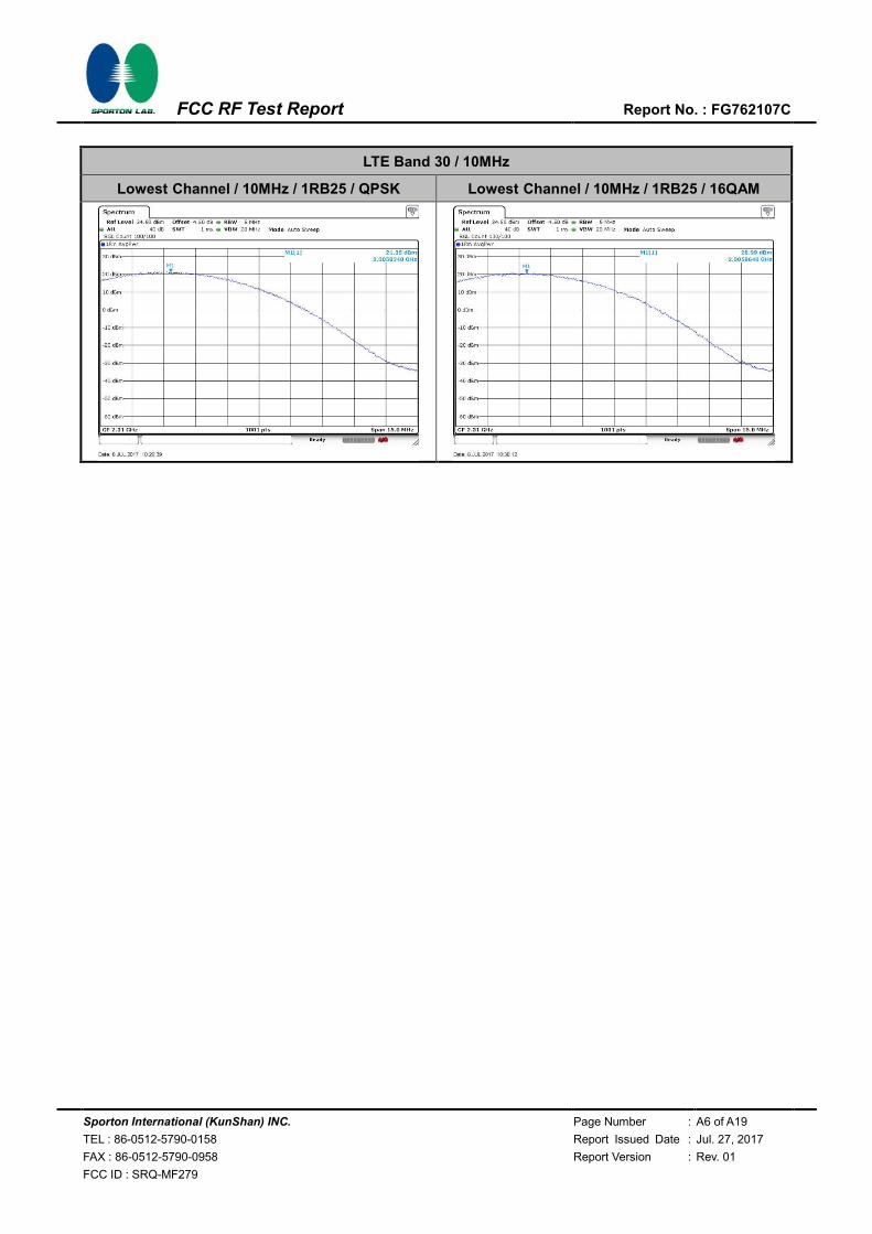
Lowest Channel / 10MHz / 1RB25 / QPSK Lowest Channel / 10MHz / 1RB25 / 16QAM
Sporton International (KunShan) INC. Page Number : A7 of A19
TEL : 86-0512-5790-0158 Report Issued Date : Jul. 27, 2017
FAX : 86-0512-5790-0958 Report Version : Rev. 01
FCC ID : SRQ-MF279
FCC RF Test Report Report No. : FG762107C
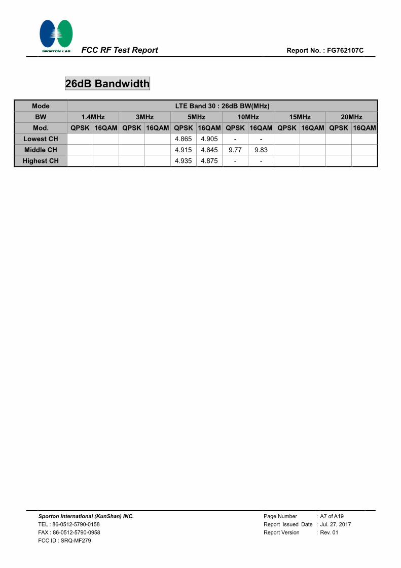
26dB Bandwidth
Mode LTE Band 30 : 26dB BW(MHz)
BW 1.4MHz 3MHz 5MHz 10MHz 15MHz 20MHz
Mod. QPSK 16QAM QPSK 16QAM QPSK 16QAM QPSK 16QAM QPSK 16QAM QPSK 16QAM
Lowest CH 4.865 4.905 - -
Middle CH 4.915 4.845 9.77 9.83
Highest CH 4.935 4.875 - -
Sporton International (KunShan) INC. Page Number : A8 of A19
TEL : 86-0512-5790-0158 Report Issued Date : Jul. 27, 2017
FAX : 86-0512-5790-0958 Report Version : Rev. 01
FCC ID : SRQ-MF279
FCC RF Test Report Report No. : FG762107C
LTE Band 30
Lowest Channel / 5MHz / QPSK Lowest Channel / 5MHz / 16QAM
Middle Channel / 5MHz / QPSK Middle Channel / 5MHz / 16QAM
Highest Channel / 5MHz / QPSK Highest Channel / 5MHz / 16QAM
Sporton International (KunShan) INC. Page Number : A9 of A19
TEL : 86-0512-5790-0158 Report Issued Date : Jul. 27, 2017
FAX : 86-0512-5790-0958 Report Version : Rev. 01
FCC ID : SRQ-MF279
FCC RF Test Report Report No. : FG762107C
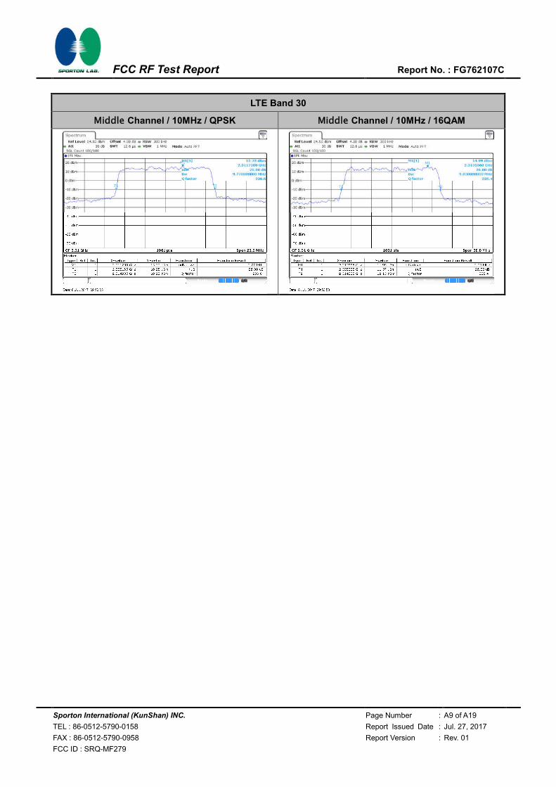
LTE Band 30
Middle Channel / 10MHz / QPSK Middle Channel / 10MHz / 16QAM
Sporton International (KunShan) INC. Page Number : A10 of A19
TEL : 86-0512-5790-0158 Report Issued Date : Jul. 27, 2017
FAX : 86-0512-5790-0958 Report Version : Rev. 01
FCC ID : SRQ-MF279
FCC RF Test Report Report No. : FG762107C
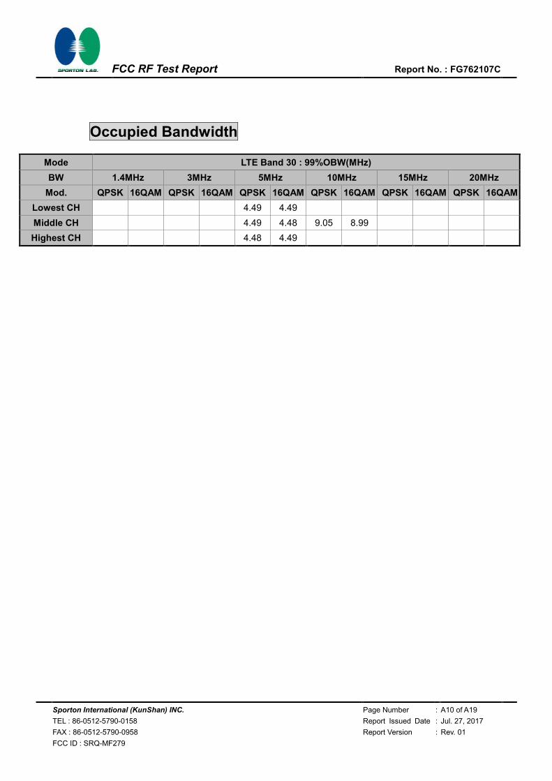
Occupied Bandwidth
Mode LTE Band 30 : 99%OBW(MHz)
BW 1.4MHz 3MHz 5MHz 10MHz 15MHz 20MHz
Mod. QPSK 16QAM QPSK 16QAM QPSK 16QAM QPSK 16QAM QPSK 16QAM QPSK 16QAM
Lowest CH 4.49 4.49
Middle CH 4.49 4.48 9.05 8.99
Highest CH 4.48 4.49

Sporton International (KunShan) INC. Page Number : A11 of A19
TEL : 86-0512-5790-0158 Report Issued Date : Jul. 27, 2017
FAX : 86-0512-5790-0958 Report Version : Rev. 01
FCC ID : SRQ-MF279
FCC RF Test Report Report No. : FG762107C
LTE Band 30
Lowest Channel / 5MHz / QPSK Lowest Channel / 5MHz / 16QAM
Middle Channel / 5MHz / QPSK Middle Channel / 5MHz / 16QAM
Highest Channel / 5MHz / QPSK Highest Channel / 5MHz / 16QAM

Sporton International (KunShan) INC. Page Number : A12 of A19
TEL : 86-0512-5790-0158 Report Issued Date : Jul. 27, 2017
FAX : 86-0512-5790-0958 Report Version : Rev. 01
FCC ID : SRQ-MF279
FCC RF Test Report Report No. : FG762107C
LTE Band 30
Middle Channel / 10MHz / QPSK Middle Channel / 10MHz / 16QAM
Sporton International (KunShan) INC. Page Number : A13 of A19
TEL : 86-0512-5790-0158 Report Issued Date : Jul. 27, 2017
FAX : 86-0512-5790-0958 Report Version : Rev. 01
FCC ID : SRQ-MF279
FCC RF Test Report Report No. : FG762107C
Conducted Band Edge
LTE Band 30 / 5MHz / QPSK
Lowest Band Edge / 1 RB Highest Band Edge / 1 RB
Lowest Band Edge / Full RB Highest Band Edge / Full RB
Sporton International (KunShan) INC. Page Number : A14 of A19
TEL : 86-0512-5790-0158 Report Issued Date : Jul. 27, 2017
FAX : 86-0512-5790-0958 Report Version : Rev. 01
FCC ID : SRQ-MF279
FCC RF Test Report Report No. : FG762107C
LTE Band 30 / 5MHz / 16QAM
Lowest Band Edge / 1RB Highest Band Edge / 1 RB
Lowest Band Edge / Full RB Highest Band Edge / Full RB

Sporton International (KunShan) INC. Page Number : A15 of A19
TEL : 86-0512-5790-0158 Report Issued Date : Jul. 27, 2017
FAX : 86-0512-5790-0958 Report Version : Rev. 01
FCC ID : SRQ-MF279
FCC RF Test Report Report No. : FG762107C
LTE Band 30 / 10MHz / QPSK
Lowest Band Edge / 1 RB Highest Band Edge / 1 RB
Band Edge / Full RB
Sporton International (KunShan) INC. Page Number : A16 of A19
TEL : 86-0512-5790-0158 Report Issued Date : Jul. 27, 2017
FAX : 86-0512-5790-0958 Report Version : Rev. 01
FCC ID : SRQ-MF279
FCC RF Test Report Report No. : FG762107C
LTE Band 30 / 10MHz / 16QAM
Lowest Band Edge / 1 RB Highest Band Edge / 1 RB
Band Edge / Full RB
Sporton International (KunShan) INC. Page Number : A17 of A19
TEL : 86-0512-5790-0158 Report Issued Date : Jul. 27, 2017
FAX : 86-0512-5790-0958 Report Version : Rev. 01
FCC ID : SRQ-MF279
FCC RF Test Report Report No. : FG762107C
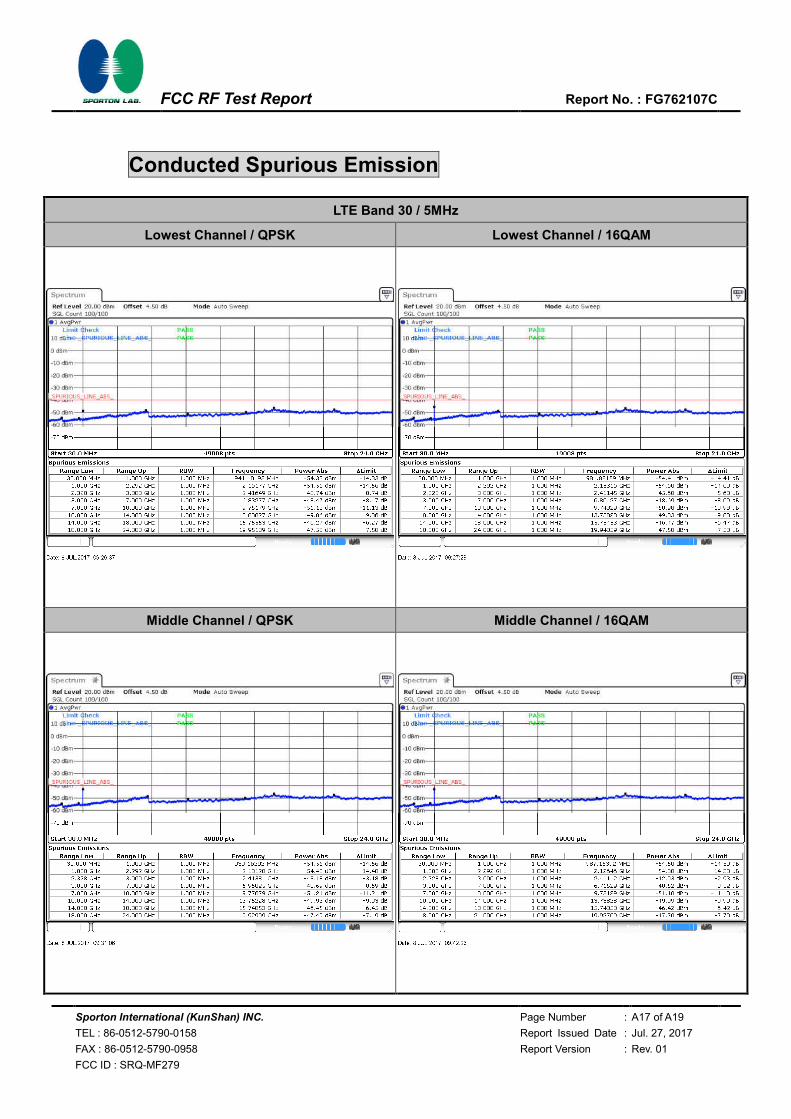
Conducted Spurious Emission
LTE Band 30 / 5MHz
Lowest Channel / QPSK Lowest Channel / 16QAM
Middle Channel / QPSK Middle Channel / 16QAM
Sporton International (KunShan) INC. Page Number : A18 of A19
TEL : 86-0512-5790-0158 Report Issued Date : Jul. 27, 2017
FAX : 86-0512-5790-0958 Report Version : Rev. 01
FCC ID : SRQ-MF279
FCC RF Test Report Report No. : FG762107C
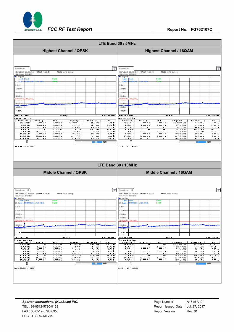
LTE Band 30 / 5MHz
Highest Channel / QPSK Highest Channel / 16QAM
LTE Band 30 / 10MHz
Middle Channel / QPSK Middle Channel / 16QAM
Sporton International (KunShan) INC. Page Number : A19 of A19
TEL : 86-0512-5790-0158 Report Issued Date : Jul. 27, 2017
FAX : 86-0512-5790-0958 Report Version : Rev. 01
FCC ID : SRQ-MF279
FCC RF Test Report Report No. : FG762107C
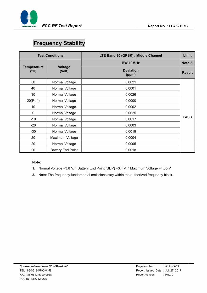
Frequency Stability
Test Conditions LTE Band 30 (QPSK) / Middle Channel Limit
Temperature (°C)
Voltage (Volt)
BW 10MHz Note 2.
Deviation (ppm)
Result
50 Normal Voltage 0.0021
PASS
40 Normal Voltage 0.0001
30 Normal Voltage 0.0026
20(Ref.) Normal Voltage 0.0000
10 Normal Voltage 0.0002
0 Normal Voltage 0.0025
-10 Normal Voltage 0.0017
-20 Normal Voltage 0.0003
-30 Normal Voltage 0.0019
20 Maximum Voltage 0.0004
20 Normal Voltage 0.0005
20 Battery End Point 0.0018
Note:
1. Normal Voltage =3.8 V.;Battery End Point (BEP) =3.4 V.;Maximum Voltage =4.35 V.
2. Note: The frequency fundamental emissions stay within the authorized frequency block.
Sporton International (KunShan) INC. Page Number : B1 of B1
TEL : 86-0512-5790-0158 Report Issued Date : Jul. 27, 2017
FAX : 86-0512-5790-0958 Report Version : Rev. 01
FCC ID : SRQ-MF279
FCC RF Test Report Report No. : FG762107C
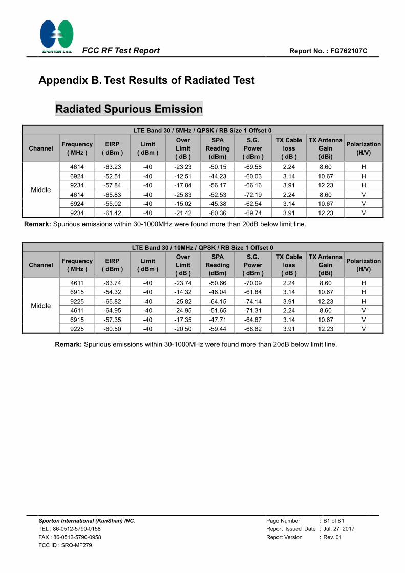
Appendix B. Test Results of Radiated Test
Radiated Spurious Emission
LTE Band 30 / 5MHz / QPSK / RB Size 1 Offset 0
Channel Frequency
( MHz )
EIRP
( dBm )
Limit
( dBm )
Over
Limit
( dB )
SPA
Reading
(dBm)
S.G.
Power
( dBm )
TX Cable
loss
( dB )
TX Antenna
Gain
(dBi)
Polarization
(H/V)
Middle
4614 -63.23 -40 -23.23 -50.15 -69.58 2.24 8.60 H
6924 -52.51 -40 -12.51 -44.23 -60.03 3.14 10.67 H
9234 -57.84 -40 -17.84 -56.17 -66.16 3.91 12.23 H
4614 -65.83 -40 -25.83 -52.53 -72.19 2.24 8.60 V
6924 -55.02 -40 -15.02 -45.38 -62.54 3.14 10.67 V
9234 -61.42 -40 -21.42 -60.36 -69.74 3.91 12.23 V
Remark: Spurious emissions within 30-1000MHz were found more than 20dB below limit line.
LTE Band 30 / 10MHz / QPSK / RB Size 1 Offset 0
Channel Frequency
( MHz )
EIRP
( dBm )
Limit
( dBm )
Over
Limit
( dB )
SPA
Reading
(dBm)
S.G.
Power
( dBm )
TX Cable
loss
( dB )
TX Antenna
Gain
(dBi)
Polarization
(H/V)
Middle
4611 -63.74 -40 -23.74 -50.66 -70.09 2.24 8.60 H
6915 -54.32 -40 -14.32 -46.04 -61.84 3.14 10.67 H
9225 -65.82 -40 -25.82 -64.15 -74.14 3.91 12.23 H
4611 -64.95 -40 -24.95 -51.65 -71.31 2.24 8.60 V
6915 -57.35 -40 -17.35 -47.71 -64.87 3.14 10.67 V
9225 -60.50 -40 -20.50 -59.44 -68.82 3.91 12.23 V
Remark: Spurious emissions within 30-1000MHz were found more than 20dB below limit line.


![OWA333010 WCDMA HSPA+ Principles RAN11 ISSUE1.11.Ppt [Last Saved by User]](https://static.fdocuments.net/doc/165x107/55cf98ec550346d0339a7b6d/owa333010-wcdma-hspa-principles-ran11-issue111ppt-last-saved-by-user.jpg)