Fatigue life prediction methodology of automotive … life prediction methodology of automotive...
7
Fatigue life prediction methodology of automotive rubber component *Chang-Su Woo 1) 1) Department of Nano Mechanics, KIMM, Daejeon 305-345, Korea 1) [email protected] ABSTRACT Fatigue life prediction and evaluation are the key technologies to assure the safety and reliability of automotive rubber components. The objective of this study is to develop the fatigue analysis process for rubber components, which is applicable to predict fatigue lifetime at initial product design step. Fatigue life prediction methodology of rubber component was proposed by incorporating the finite element analysis and fatigue damage parameter of maximum Green-Lagrange strains appearing at the critical location determined from fatigue test. The fatigue lifetime of rubber component was effectively represented by the maximum Green-Lagrange strain. Predicted fatigue lifetime of the rubber component was in fairly good agreements with the experimental lifetime. 1. INTRODUCTION Rubber materials are used usually in many industries because of their large reversible elastic deformation, damping and energy absorption characteristics (Evans, 2001). The fatigue life prediction on the rubber components was increasing according to the extension of warranty period of the automotive components. A design of rubber components against fatigue failure is one of the critical issues to prevent the failures during the operation. Therefore, fatigue lifetime prediction and evaluation are the key technologies to assure the safety and reliability of mechanical rubber components Fatigue lifetime evaluation of rubber components has hitherto relied mainly on a real load test, road simulator test or bench fatigue test (Lake, 1995). Although above methods have advantages in accuracy of fatigue life, but cannot be used before the first prototype is made and the fatigue test should be always conducted whenever material or geometry changes are made (Hirakawa, 1978). In order to predict the fatigue life of the rubber components at the design stage, a simple procedure of lifetime prediction is suggested in Fig. 1. In this paper, engine mount insulator for automobile, which is damaged by repeated loading during operation, is selected for a typical application of fatigue life 1) Dr, Principal researcher
Transcript of Fatigue life prediction methodology of automotive … life prediction methodology of automotive...
Fatigue life prediction methodology of automotive rubber component
*Chang-Su Woo1)
1) Department of Nano Mechanics, KIMM, Daejeon 305-345, Korea
ABSTRACT
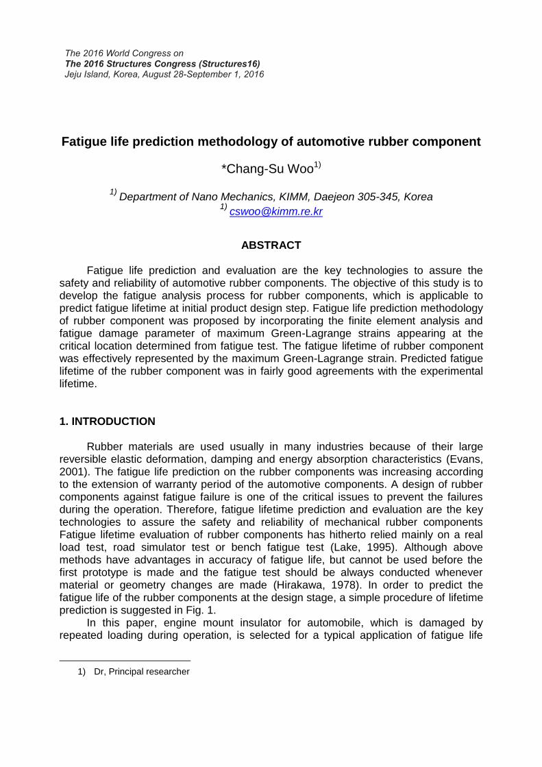
Fatigue life prediction and evaluation are the key technologies to assure the safety and reliability of automotive rubber components. The objective of this study is to develop the fatigue analysis process for rubber components, which is applicable to predict fatigue lifetime at initial product design step. Fatigue life prediction methodology of rubber component was proposed by incorporating the finite element analysis and fatigue damage parameter of maximum Green-Lagrange strains appearing at the critical location determined from fatigue test. The fatigue lifetime of rubber component was effectively represented by the maximum Green-Lagrange strain. Predicted fatigue lifetime of the rubber component was in fairly good agreements with the experimental lifetime. 1. INTRODUCTION Rubber materials are used usually in many industries because of their large reversible elastic deformation, damping and energy absorption characteristics (Evans, 2001). The fatigue life prediction on the rubber components was increasing according to the extension of warranty period of the automotive components. A design of rubber components against fatigue failure is one of the critical issues to prevent the failures during the operation. Therefore, fatigue lifetime prediction and evaluation are the key technologies to assure the safety and reliability of mechanical rubber components Fatigue lifetime evaluation of rubber components has hitherto relied mainly on a real load test, road simulator test or bench fatigue test (Lake, 1995). Although above methods have advantages in accuracy of fatigue life, but cannot be used before the first prototype is made and the fatigue test should be always conducted whenever material or geometry changes are made (Hirakawa, 1978). In order to predict the fatigue life of the rubber components at the design stage, a simple procedure of lifetime prediction is suggested in Fig. 1.
In this paper, engine mount insulator for automobile, which is damaged by repeated loading during operation, is selected for a typical application of fatigue life
1) Dr, Principal researcher
prediction methodology developed in the research. Simple tension, equi-biaxial tension and planar test were conducted to determine the nonlinear material constants of the rubber components. The maximum Green-Lagrange strain of 3-dimensional dumbbell specimens and engine mount insulator were obtained from the nonlinear finite element analysis using the hyper-elastic material model determined from the material tests. We used the 3-dimensional dumbbell specimens to evaluate the fatigue life of rubber materials. Fatigue tests of 3-dimensional dumbbell specimens with various mean strains were performed, and a fatigue life curve equation represented by the maximum Green-Lagrange strain was obtained. Fatigue lifetime prediction of engine mount insulator was made by incorporating the maximum Green-Lagrange strain values, which was evaluated from the finite element analysis and fatigue tests, respectively. Predicted fatigue lives of the rubber component showed a fairly good agreement with the experimental fatigue lives. Fatigue analysis procedure employed in this study could be used approximately for the fatigue design.
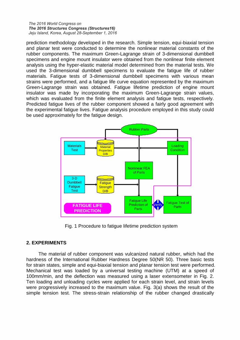
Fig. 1 Procedure to fatigue lifetime prediction system 2. EXPERIMENTS The material of rubber component was vulcanized natural rubber, which had the hardness of the International Rubber Hardness Degree 50(NR 50). Three basic tests for strain states, simple and equi-biaxial tension and planar tension test were performed. Mechanical test was loaded by a universal testing machine (UTM) at a speed of 100mm/min, and the deflection was measured using a laser extensometer in Fig. 2. Ten loading and unloading cycles were applied for each strain level, and strain levels were progressively increased to the maximum value. Fig. 3(a) shows the result of the simple tension test. The stress-strain relationship of the rubber changed drastically
Rubber Parts
Materials
TestMaterial
Properties
D/B
Fatigue Test of
Parts
Fatigue Life
Prediction of
Parts
3-D
Dumbbell
Fatigue
Test
Fatigue
Strength
D/B
Loading
Condition
Verify
Nonlinear FEA
of Parts
FATIGUE LIFE
PREDICTION
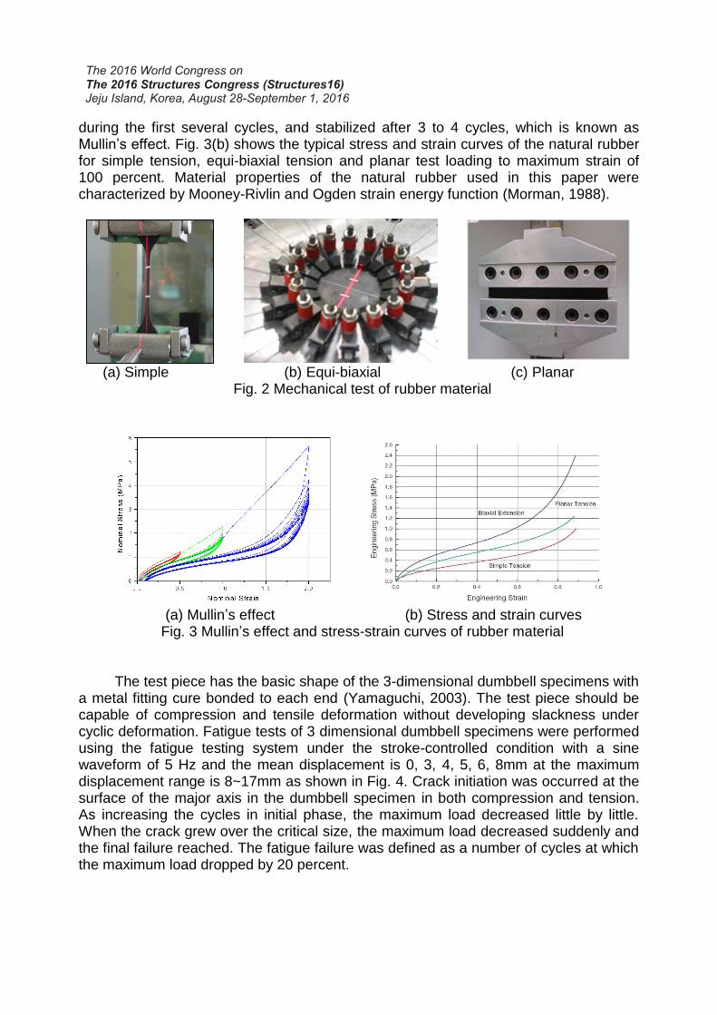
during the first several cycles, and stabilized after 3 to 4 cycles, which is known as Mullin’s effect. Fig. 3(b) shows the typical stress and strain curves of the natural rubber for simple tension, equi-biaxial tension and planar test loading to maximum strain of 100 percent. Material properties of the natural rubber used in this paper were characterized by Mooney-Rivlin and Ogden strain energy function (Morman, 1988).
(a) Simple (b) Equi-biaxial (c) Planar
Fig. 2 Mechanical test of rubber material
(a) Mullin’s effect (b) Stress and strain curves
Fig. 3 Mullin’s effect and stress-strain curves of rubber material
The test piece has the basic shape of the 3-dimensional dumbbell specimens with a metal fitting cure bonded to each end (Yamaguchi, 2003). The test piece should be capable of compression and tensile deformation without developing slackness under cyclic deformation. Fatigue tests of 3 dimensional dumbbell specimens were performed using the fatigue testing system under the stroke-controlled condition with a sine waveform of 5 Hz and the mean displacement is 0, 3, 4, 5, 6, 8mm at the maximum displacement range is 8~17mm as shown in Fig. 4. Crack initiation was occurred at the surface of the major axis in the dumbbell specimen in both compression and tension. As increasing the cycles in initial phase, the maximum load decreased little by little. When the crack grew over the critical size, the maximum load decreased suddenly and the final failure reached. The fatigue failure was defined as a number of cycles at which the maximum load dropped by 20 percent.
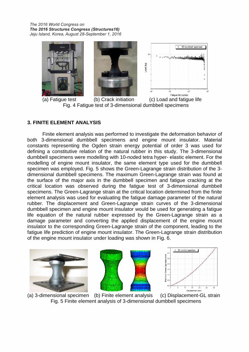
(a) Fatigue test (b) Crack initiation (c) Load and fatigue life
Fig. 4 Fatigue test of 3-dimensional dumbbell specimens
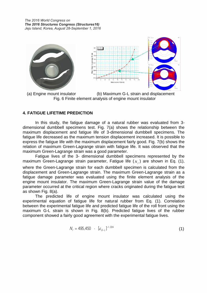
3. FINITE ELEMENT ANALYSIS Finite element analysis was performed to investigate the deformation behavior of
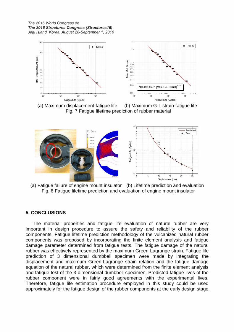
both 3-dimensional dumbbell specimens and engine mount insulator. Material constants representing the Ogden strain energy potential of order 3 was used for defining a constitutive relation of the natural rubber in this study. The 3-dimensional dumbbell specimens were modelling with 10-noded tetra hyper- elastic element. For the modelling of engine mount insulator, the same element type used for the dumbbell specimen was employed. Fig. 5 shows the Green-Lagrange strain distribution of the 3- dimensional dumbbell specimens. The maximum Green-Lagrange strain was found at the surface of the major axis in the dumbbell specimen and fatigue cracking at the critical location was observed during the fatigue test of 3-dimensional dumbbell specimens. The Green-Lagrange strain at the critical location determined from the finite element analysis was used for evaluating the fatigue damage parameter of the natural rubber. The displacement and Green-Lagrange strain curves of the 3-dimensional dumbbell specimen and engine mount insulator would be used for generating a fatigue life equation of the natural rubber expressed by the Green-Lagrange strain as a damage parameter and converting the applied displacement of the engine mount insulator to the corresponding Green-Lagrange strain of the component, leading to the fatigue life prediction of engine mount insulator. The Green-Lagrange strain distribution of the engine mount insulator under loading was shown in Fig. 6.
(a) 3-dimensional specimen (b) Finite element analysis (c) Displacement-GL strain
Fig. 5 Finite element analysis of 3-dimensional dumbbell specimens
(a) Engine mount insulator (b) Maximum G-L strain and displacement
Fig. 6 Finite element analysis of engine mount insulator
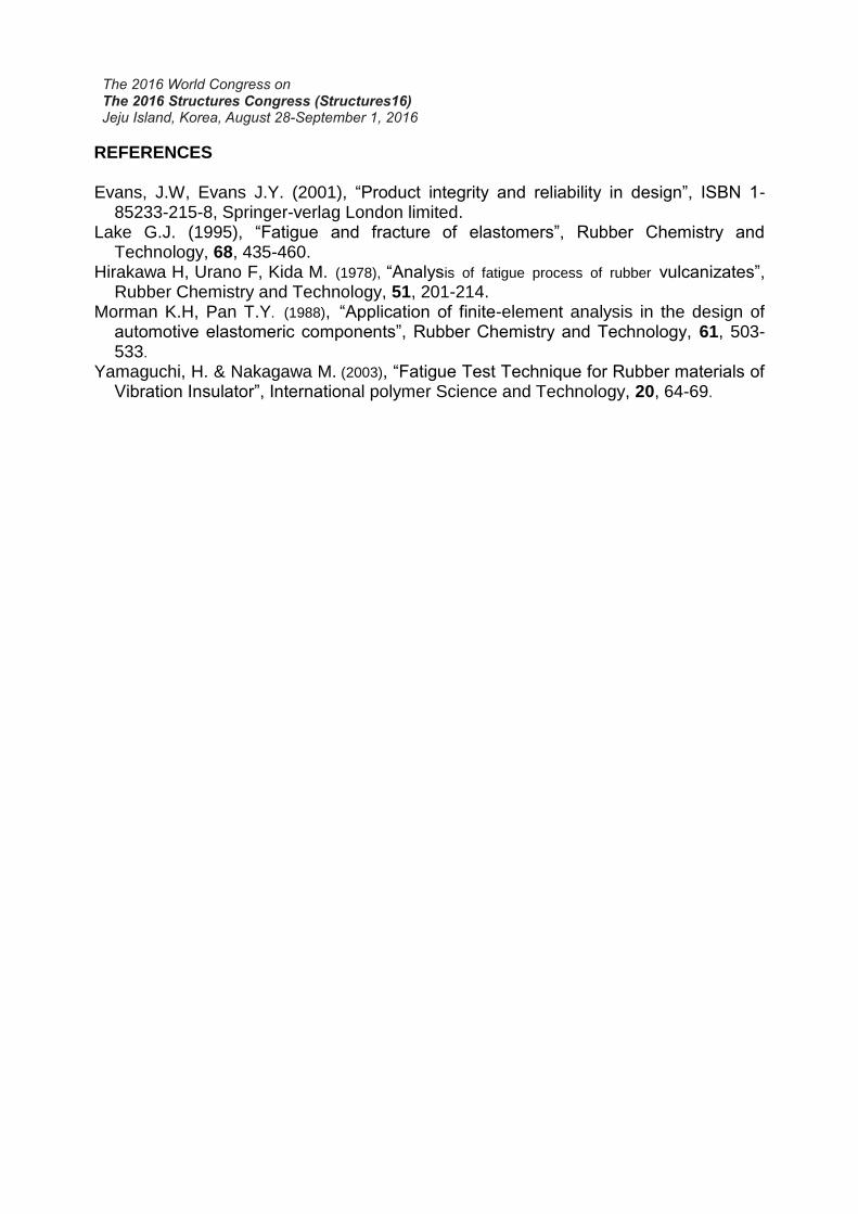
4. FATIGUE LIFETIME PREDICTION In this study, the fatigue damage of a natural rubber was evaluated from 3-
dimensional dumbbell specimens test. Fig. 7(a) shows the relationship between the maximum displacement and fatigue life of 3-dimensional dumbbell specimens. The fatigue life decreased as the maximum tension displacement increased. It is possible to express the fatigue life with the maximum displacement fairly good. Fig. 7(b) shows the relation of maximum Green-Lagrange strain with fatigue life. It was observed that the maximum Green-Lagrange strain was a good parameter.
Fatigue lives of the 3- dimensional dumbbell specimens represented by the maximum Green-Lagrange strain parameter, Fatigue life (
fN ) are shown in Eq. (1),
where the Green-Lagrange strain for each dumbbell specimen is calculated from the displacement and Green-Lagrange strain. The maximum Green-Lagrange strain as a fatigue damage parameter was evaluated using the finite element analysis of the engine mount insulator. The maximum Green-Lagrange strain value of the damage parameter occurred at the critical region where cracks originated during the fatigue test as shown Fig. 8(a).
The predicted life of engine mount insulator was calculated using the experimental equation of fatigue life for natural rubber from Eq. (1). Correlation between the experimental fatigue life and predicted fatigue life of the roll front using the maximum G-L strain is shown in Fig. 8(b). Predicted fatigue lives of the rubber component showed a fairly good agreement with the experimental fatigue lives.
324.1][450,495
LGfN (1)
(a) Maximum displacement-fatigue life (b) Maximum G-L strain-fatigue life
Fig. 7 Fatigue lifetime prediction of rubber material
(a) Fatigue failure of engine mount insulator (b) Lifetime prediction and evaluation
Fig. 8 Fatigue lifetime prediction and evaluation of engine mount insulator
5. CONCLUSIONS
The material properties and fatigue life evaluation of natural rubber are very important in design procedure to assure the safety and reliability of the rubber components. Fatigue lifetime prediction methodology of the vulcanized natural rubber components was proposed by incorporating the finite element analysis and fatigue damage parameter determined from fatigue tests. The fatigue damage of the natural rubber was effectively represented by the maximum Green-Lagrange strain. Fatigue life prediction of 3 dimensional dumbbell specimen were made by integrating the displacement and maximum Green-Lagrange strain relation and the fatigue damage equation of the natural rubber, which were determined from the finite element analysis and fatigue test of the 3 dimensional dumbbell specimen. Predicted fatigue lives of the rubber component were in fairly good agreements with the experimental lives. Therefore, fatigue life estimation procedure employed in this study could be used approximately for the fatigue design of the rubber components at the early design stage.
REFERENCES Evans, J.W, Evans J.Y. (2001), “Product integrity and reliability in design”, ISBN 1-
85233-215-8, Springer-verlag London limited. Lake G.J. (1995), “Fatigue and fracture of elastomers”, Rubber Chemistry and
Technology, 68, 435-460. Hirakawa H, Urano F, Kida M. (1978), “Analysis of fatigue process of rubber vulcanizates”,
Rubber Chemistry and Technology, 51, 201-214.
Morman K.H, Pan T.Y. (1988), “Application of finite-element analysis in the design of automotive elastomeric components”, Rubber Chemistry and Technology, 61, 503-533.
Yamaguchi, H. & Nakagawa M. (2003), “Fatigue Test Technique for Rubber materials of Vibration Insulator”, International polymer Science and Technology, 20, 64-69.