
Fast track construction of 9.5 km long elevated expressway...
6
Tailor Made Concrete Structures – Walraven & Stoelhorst (eds) © 2008Taylor & Francis Group, London, ISBN 978-0-415-47535-8 Fast track construction of 9.5km long elevated expressway by largescale, prefabrication of superstructure S. Sengupta Span Consultants Pvt. Ltd., Bangalore, India ABSTRACT: The traffic volume on existing national highway no. 7 from Bangalore city to Hosur city in southern India has substantially increased in recent years to an extent much beyond the capacity of the 4-lane highway. Apart from being a common stretch to the Golden Quadrilateral and North-South corridor of national highway network in India, this stretch provides daily access to large number of InformationTechnology and Bio-Technology professionals in Bangalore who commutes daily to the Electronic city appx. 9.5km away from the downtown area. Due to the severe traffic congestion and consequent loss of precious man-hours on the road, the authorities had decided to construct an elevated expressway all along the road with full access control and tolling for providing a dedicated fast access on this corridor. The four-lane superstructure takes off just after an existing flyover recently built and run straight into the Electronic City, Phase I & II approx. 9.5km away. The elevated viaduct alongwith a multilevel interchange at the terminal point is being constructed on Build Operate & Transfer (BOT) basis using large – scale precast prestressed concrete (PSC) segmental, glued, matchcast technology and erected by Overhead Launching Girders without using any ground scaffold to avoid any traffic disturbance at GL.The four-lane superstructure is supported on single row of piers to be constructed along the central median of the highway.This is presently the longest flyover under construction in India. Fig. 1 shows a general view of the elevated expressway. 1 PRECAST/PREFAB CONSTRUCTION For the elevated viaduct superstructure, largescale precast segmental construction has been adopted. The precast construction will have following advan- tages. – reduction in construction time due to concurrent working for foundations and superstructure. – minimal interference to flowing traffic at ground level. – superior quality control due to factory condition of concreting in precasting yard. – environment – friendly as no site concreting work is involved for the superstructure. Figure 1. General view of the elevated expressway. For this project, fast track construction is of extreme importance since the project is financed by BOT Con- cessionaire and he can start earning the toll revenue only after the facilities are opened to traffic. In addi- tion to the precast segmental superstructure (grade M50), prefabrication has been adopted for several other structural elements e.g. – precast crash barrier, total length 22 km, grade M40 – precast central median, total length 22 km, grade M40 – precast closed box drain, total length 18 km, grade M30 – precast fascia panels of reinforced earth walls, grade M30 – precast PSC contiguous I-girders, grade M50 – precast sacrificial RC planks for deck, grade M30 2 STRUCTURAL ARRANGEMENT The existing highway crosses numbers of cross-roads at GL and major junctions all along the length. The span configuration of the elevated viaduct has been finally evolved after a number of trials to cater to these locations of existing cross roads and other site specific constraints viz. 987
Transcript of Fast track construction of 9.5 km long elevated expressway...
Tailor Made Concrete Structures – Walraven & Stoelhorst (eds)© 2008 Taylor & Francis Group, London, ISBN 978-0-415-47535-8
Fast track construction of 9.5 km long elevated expressway bylargescale, prefabrication of superstructure
S. SenguptaSpan Consultants Pvt. Ltd., Bangalore, India
ABSTRACT: The traffic volume on existing national highway no. 7 from Bangalore city to Hosur city insouthern India has substantially increased in recent years to an extent much beyond the capacity of the 4-lanehighway. Apart from being a common stretch to the Golden Quadrilateral and North-South corridor of nationalhighway network in India, this stretch provides daily access to large number of Information Technology andBio-Technology professionals in Bangalore who commutes daily to the Electronic city appx. 9.5 km away fromthe downtown area. Due to the severe traffic congestion and consequent loss of precious man-hours on the road,the authorities had decided to construct an elevated expressway all along the road with full access control andtolling for providing a dedicated fast access on this corridor.
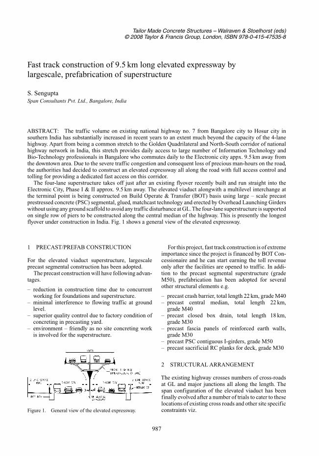
The four-lane superstructure takes off just after an existing flyover recently built and run straight into theElectronic City, Phase I & II approx. 9.5 km away. The elevated viaduct alongwith a multilevel interchange atthe terminal point is being constructed on Build Operate & Transfer (BOT) basis using large – scale precastprestressed concrete (PSC) segmental, glued, matchcast technology and erected by Overhead Launching Girderswithout using any ground scaffold to avoid any traffic disturbance at GL.The four-lane superstructure is supportedon single row of piers to be constructed along the central median of the highway. This is presently the longestflyover under construction in India. Fig. 1 shows a general view of the elevated expressway.
1 PRECAST/PREFAB CONSTRUCTION
For the elevated viaduct superstructure, largescaleprecast segmental construction has been adopted.
The precast construction will have following advan-tages.
– reduction in construction time due to concurrentworking for foundations and superstructure.
– minimal interference to flowing traffic at groundlevel.
– superior quality control due to factory condition ofconcreting in precasting yard.
– environment – friendly as no site concreting workis involved for the superstructure.
Figure 1. General view of the elevated expressway.
For this project, fast track construction is of extremeimportance since the project is financed by BOT Con-cessionaire and he can start earning the toll revenueonly after the facilities are opened to traffic. In addi-tion to the precast segmental superstructure (gradeM50), prefabrication has been adopted for severalother structural elements e.g.
– precast crash barrier, total length 22 km, grade M40– precast central median, total length 22 km,
grade M40– precast closed box drain, total length 18 km,
grade M30– precast fascia panels of reinforced earth walls,
grade M30– precast PSC contiguous I-girders, grade M50– precast sacrificial RC planks for deck, grade M30
2 STRUCTURAL ARRANGEMENT
The existing highway crosses numbers of cross-roadsat GL and major junctions all along the length. Thespan configuration of the elevated viaduct has beenfinally evolved after a number of trials to cater to theselocations of existing cross roads and other site specificconstraints viz.
987
– Existing subsoil conditions and maximum capacityof the piled foundations.
– Maximum repetitions of modules to effect savingsin time and cost.
– Constraints in width of pile cap on existing centralmedian.
– Feasible method of precast superstructure erectionas per site condition.
After considering various alternatives, the spanarrangement has been worked out in the range of29 m to 34 m. Major part of the precast segmen-tal viaduct are with continuous span modules of29 m + 6 × 34 m + 29 m = 262 m as a standard mod-ule. There are 28 nos. of such modules and also 15 nosstructure modules with different span configurationsin the entire 9.5 km stretch. The multilevel interchangeat the terminal point comprises sharply curved PSCbox girders in the loops. The interchange is beingconstructed with a combination of in-situ and precasttechnology.
3 PRECAST SEGMENTAL SUPERSTRUCTURE
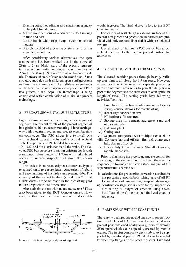
Figure 2 shows cross-section through a typical precastsegment. The overall width of the precast segmentalbox girder is 16.4 m accommodating 4-lane carriage-way with a central median and precast crash barrierson each edge. The PSC girder is a twin-cell onewith inclined external webs and a central verticalweb. The permanent PT bonded tendons are of size19 × 0.6” and are distributed in all the webs. The ele-vated PSC box structure is having uniform depth witha minimum clear height of 1.70 m with unhinderedaccess for internal inspection all along the 9.5 kmlength.
The deck slab has been designed as transversely posttensioned units to ensure lesser congestion of rebarsand easy handling of the wide cantilevering slabs. Thestressing of these short tendons (size 4 × 0.6” in flatHDPE ducts) are to be made in the precasting yardbefore despatch to site for erection.
Alternatively, option without any transverse PT hasalso been given to the BOT Concessionaire. How-ever, in that case the rebar content in deck slab
Figure 2. Section thru typical precast segment.
would increase. The final choice is left to the BOTConcessionaire.
For reasons of aesthetics, the external surface of theprecast box girder and precast crash barriers are pro-vided with polyurethane liner finish with pre-selectedtexture.
Overall shape of the in-situ PSC curved box girderis kept identical to that of the precast portion foraesthetics.
4 PRECASTING METHOD FOR SEGMENTS
The elevated corridor passes through heavily built-up area almost all along the 9.5 km route. However,it was possible to arrange two separate precastingyards of adequate area so as to plan the daily trans-port of the segments to the erection site with optimumlength of travel. The casting yards have followingactivities/facilities.
i) Long line or short line moulds area on jacks withsurvey control stations for matchcasting
ii) Rebar cage fabrication areaiii) PT hardware fixture areaiv) Storage area for cement, aggregate, sand and
other materialsv) Batching plant
vi) Curing areavii) Segment storage area with multiple-tier stackingviii) Concrete lab and offices, first aid, conference
hall, design office etc.ix) Heavy duty Goliath cranes, Straddle Carriers,
mobile cranes etc.
Prior to finalising the precise geometric control forconcreting of the segments and finalising the erectionsequence, following construction stage analysis of thesuperstructure is carried out:
i) calculations for pre-camber correction required inthe precasting moulds/beds taking care of all PTforces, effects of temperature, creep and shrinkage.
ii) construction stage stress check for the superstruc-ture during all stages of erection using Over-head Launching Girders as per finalized erectionsequence.
5 RAMP SPANS WITH PRECAST UNITS
There are two ramps, one up and one down, superstruc-ture of which is of 8.3 m width and constructed withprecast post-tensioned contiguous girders of average25 m spans which can be speedily erected by mobilecranes. The in-situ composite deck slab is to be sup-ported by sacrificial precast RC planks to be erectedbetween top flanges of the precast girders. Live load
988
continuity over 5 or 6 spans are ensured through in-situRC diaphragms at the pier locations.
6 BASIS OF LAUNCHING SCHEME
The cardinal principles adopted for evolving thelaunching/erection method for such largescale precastunits at the site are as follows:
i) Under no circumstances, shall traffic flow on theexisting highway at ground level be disturbed.
ii) The minimum carriageway width on the high-way at ground level during the entire period ofconstruction shall be maintained 8.75 m in eachdirection, except while widening the existing car-riageway, when this can be 7.50 m minimum. Alsoconstruction of service lanes in such lengths shallbe completed prior to start of widening of existingcarriageway.
iii) No ground scaffold shall be erected during theentire construction period for construction ofsuperstructure.
iv) For construction of interchange near ElectronicCity, adequate number of casting trusses of ade-quate spans shall be used for construction ofin-situ box girders without erecting any groundscaffold affecting the traffic flow.
v) For constructing the elevated road, maximumwidth of the barricaded zone at the existing centralmedian shall be limited to 8.5 m.
vi) The entire construction should be completed in 24months.
7 ERECTION OF PRECAST SEGMENTALVIADUCT
Appx. total nos of precast segments : 3200Maximum weight of one segment : Normal : 80tsegment
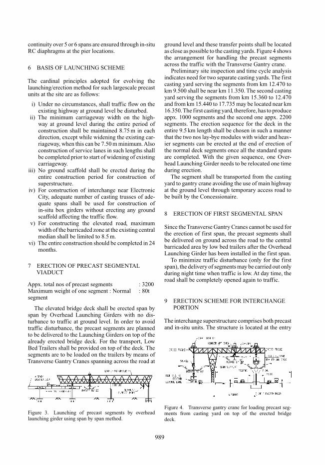
The elevated bridge deck shall be erected span byspan by Overhead Launching Girders with no dis-turbance to traffic at ground level. In order to avoidtraffic disturbance, the precast segments are plannedto be delivered to the Launching Girders on top of thealready erected bridge deck. For the transport, LowBed Trailers shall be provided on top of the deck. Thesegments are to be loaded on the trailers by means ofTransverse Gantry Cranes spanning across the road at
Figure 3. Launching of precast segments by overheadlaunching girder using span by span method.
ground level and these transfer points shall be locatedas close as possible to the casting yards. Figure 4 showsthe arrangement for handling the precast segmentsacross the traffic with the Transverse Gantry crane.
Preliminary site inspection and time cycle analysisindicates need for two separate casting yards. The firstcasting yard serving the segments from km 12.470 tokm 9.500 shall be near km 11.350. The second castingyard serving the segments from km 15.360 to 12.470and from km 15.440 to 17.735 may be located near km16.350.The first casting yard, therefore, has to produceappx. 1000 segments and the second one appx. 2200segments. The erection sequence for the deck in theentire 9.5 km length shall be chosen in such a mannerthat the two nos lay-bye modules with wider and heav-ier segments can be erected at the end of erection ofthe normal deck segments once all the standard spansare completed. With the given sequence, one Over-head Launching Girder needs to be relocated one timeduring erection.
The segment shall be transported from the castingyard to gantry crane avoiding the use of main highwayat the ground level through temporary access road tobe built by the Concessionaire.
8 ERECTION OF FIRST SEGMENTAL SPAN
Since the Transverse Gantry Cranes cannot be used forthe erection of first span, the precast segments shallbe delivered on ground across the road to the centralbarricaded area by low bed trailers after the OverheadLaunching Girder has been installed in the first span.
To minimize traffic disturbance (only for the firstspan), the delivery of segments may be carried out onlyduring night time when traffic is low. At day time, theroad shall be completely opened again to traffic.
9 ERECTION SCHEME FOR INTERCHANGEPORTION
The interchange superstructure comprises both precastand in-situ units. The structure is located at the entry
Figure 4. Transverse gantry crane for loading precast seg-ments from casting yard on top of the erected bridgedeck.
989
to the Electronic City where large volume of IT trafficpasses everyday and as such, the construction schemeshall be so as to ensure no traffic disturbance/closureon the existing highway at GL.
The PSC precast I – girders (for 25 m spans) shallbe manufactured close to the erection site and erectedon pier caps by mobile cranes. End diaphragms shallbe cast-in-situ. Temporary structural steel supportingbrackets with temporary bearings are planned to beused for supporting the end precast girders till thein-situ diaphragms are fully commissioned.
The PSC in-situ box girders shall be concreted onsuitably designed temporary structural steel castingtruss (nos of plate girders of shallow depth with crossbeams to ensure maximum vertical moving clearance)spanning between the piers thereby avoiding closureof any span for moving traffic at GL.
10 ERECTION SEQUENCE AND CYCLE TIME
Span by span erection of superstructure with precastsegments has been adopted and the major steps oferection sequence are as follows:
Detailed time-study analysis of all activities hasbeen carried out and the target cycle time per spanis 5 days (average). With the site mobilisation plannedand earlier experience in similar projects, it is foundachievable. Even, after the initial learning curve, it isexpected to reduce the average cycle time to from 5 to 3days per span. Cast-in-situ stitch has been incorporatedin the precast segmental superstructure (@ approx.one per span) for compensating manufacturing toler-ances, effects of creep and shrinkage. The thicknessof in-situ stitch preferably should not exceed 200 mmsand should be of richer grade than that of the precastsegments.
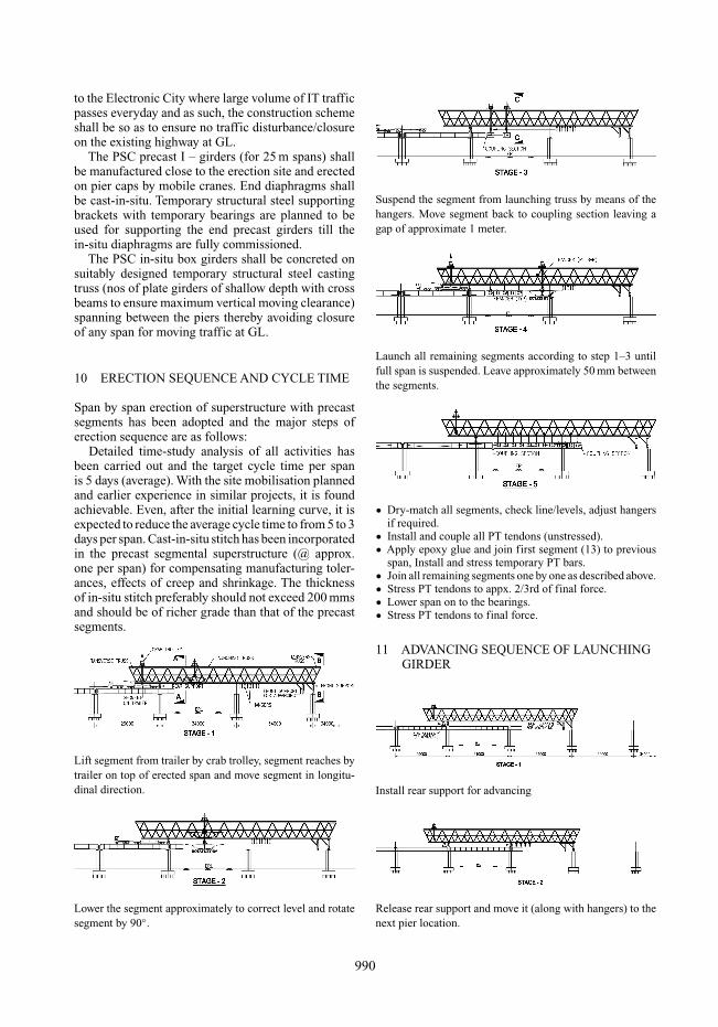
Lift segment from trailer by crab trolley, segment reaches bytrailer on top of erected span and move segment in longitu-dinal direction.
Lower the segment approximately to correct level and rotatesegment by 90◦.
Suspend the segment from launching truss by means of thehangers. Move segment back to coupling section leaving agap of approximate 1 meter.
Launch all remaining segments according to step 1–3 untilfull span is suspended. Leave approximately 50 mm betweenthe segments.
• Dry-match all segments, check line/levels, adjust hangersif required.
• Install and couple all PT tendons (unstressed).• Apply epoxy glue and join first segment (13) to previous
span, Install and stress temporary PT bars.• Join all remaining segments one by one as described above.• Stress PT tendons to appx. 2/3rd of final force.• Lower span on to the bearings.• Stress PT tendons to final force.
11 ADVANCING SEQUENCE OF LAUNCHINGGIRDER
Install rear support for advancing
Release rear support and move it (along with hangers) to thenext pier location.
990
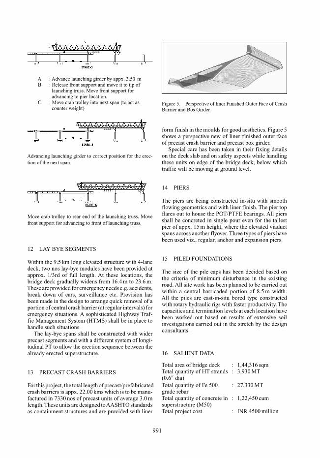
A : Advance launching girder by appx. 3.50 mB : Release front support and move it to tip of
launching truss. Move front support foradvancing to pier location.
C : Move crab trolley into next span (to act ascounter weight)
Advancing launching girder to correct position for the erec-tion of the next span.
Move crab trolley to rear end of the launching truss. Movefront support for advancing to front of launching truss.
12 LAY BYE SEGMENTS
Within the 9.5 km long elevated structure with 4-lanedeck, two nos lay-bye modules have been provided atapprox. 1/3rd of full length. At these locations, thebridge deck gradually widens from 16.4 m to 23.6 m.These are provided for emergency needs e.g. accidents,break down of cars, surveillance etc. Provision hasbeen made in the design to arrange quick removal of aportion of central crash barrier (at regular intervals) foremergency situations. A sophisticated Highway Traf-fic Management System (HTMS) shall be in place tohandle such situations.
The lay-bye spans shall be constructed with widerprecast segments and with a different system of longi-tudinal PT to allow the erection sequence between thealready erected superstructure.
13 PRECAST CRASH BARRIERS
For this project, the total length of precast/prefabricatedcrash barriers is appx. 22.00 kms which is to be manu-factured in 7330 nos of precast units of average 3.0 mlength.These units are designed toAASHTO standardsas containment structures and are provided with liner
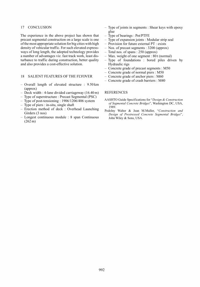
Figure 5. Perspective of liner Finished Outer Face of CrashBarrier and Bos Girder.
form finish in the moulds for good aesthetics. Figure 5shows a perspective new of liner finished outer faceof precast crash barrier and precast box girder.
Special care has been taken in their fixing detailson the deck slab and on safety aspects while handlingthese units on edge of the bridge deck, below whichtraffic will be moving at ground level.
14 PIERS
The piers are being constructed in-situ with smoothflowing geometrics and with liner finish. The pier topflares out to house the POT/PTFE bearings. All piersshall be concreted in single pour even for the tallestpier of appx. 15 m height, where the elevated viaductspans across another flyover. Three types of piers havebeen used viz., regular, anchor and expansion piers.
15 PILED FOUNDATIONS
The size of the pile caps has been decided based onthe criteria of minimum disturbance in the existingroad. All site work has been planned to be carried outwithin a central barricaded portion of 8.5 m width.All the piles are cast-in-situ bored type constructedwith rotary hydraulic rigs with faster productivity. Thecapacities and termination levels at each location havebeen worked out based on results of extensive soilinvestigations carried out in the stretch by the designconsultants.
16 SALIENT DATA
Total area of bridge deck : 1,44,316 sqmTotal quantity of HT strands : 3,930 MT(0.6′′ dia)Total quantity of Fe 500 : 27,330 MTgrade rebarTotal quantity of concrete in : 1,22,450 cumsuperstructure (M50)Total project cost : INR 4500 million
991
17 CONCLUSION
The experience in the above project has shown thatprecast segmental construction on a large scale is oneof the most appropriate solution for big cities with highdensity of vehicular traffic. For such elevated express-ways of long length, the adopted technology providesa number of advantages viz. fast track work, least dis-turbance to traffic during construction, better qualityand also provides a cost-effective solution.
18 SALIENT FEATURES OF THE FLYOVER
– Overall length of elevated structure : 9.50 km(approx)
– Deck width : 4-lane divided carriageway (16.40 m)– Type of superstructure : Precast Segmental (PSC)– Type of post-tensioning : 1906/1206/406 system– Type of piers : in-situ, single shaft– Erection method of deck : Overhead Launching
Girders (3 nos)– Longest continuous module : 8 span Continuous
(262 m)
– Type of joints in segments : Shear keys with epoxyglue
– Type of bearings : Pot/PTFE– Type of expansion joints : Modular strip seal– Provision for future external PT : exists– Nos. of precast segments : 3200 (approx)– Total nos. of spans : 250 (approx)– Max. weight of one segment : 80 t (normal)– Type of foundations : bored piles driven by
Hydraulic rigs– Concrete grade of precast segments : M50– Concrete grade of normal piers : M50– Concrete grade of anchor piers : M60– Concrete grade of crash barriers : M40
REFERENCES
AASHTO Guide Specifications for “Design & Constructionof Segmental Concrete Bridges”, Washington DC, USA,1989.
Podolny Walter & Jean M.Muller, “Construction andDesign of Prestressed Concrete Segmental Bridges”,John Wiley & Sons, USA.
992