Failure Prediction of Fiber Reinforced Polymer Pipes using … · Abstract— Numerical study is...
6
International Journal of Engineering and Technical Research (IJETR) ISSN: 2321-0869 (O) 2454-4698 (P), Volume-4, Issue-2, February 2016 115 www.erpublication.org Abstract— Numerical study is done to predict the failure of fiber reinforced polymer pipes produced by filament winding when subjected to pure internal pressure. The analysis is done using the last ply failure technique for a four layered pipe oriented anti-symmetrically [±Ø°] 2 . ANSYS Composite PrepPost (version 15) is used for analysis. Three different composites were examined in this study: E-glass fiber/epoxy, carbon fiber/epoxy and aramid fiber/epoxy. Numerical analysis was further validated through experimental data in case of E- glass fiber/epoxy composite. Comparison proves a good degree of correlation. The maximum burst pressure for the three types of material is realised at [±55°] 2 compared to a minimum pressure at [±0°] 2 . Index Terms—Failure analysis, Filament winding, Finite element analysis, Polymer matrix composites. I. INTRODUCTION Advanced composite materials are nowadays used to fabricate many structural parts in engineering applications due to their promising properties compared to other monolithic materials. Composite materials offer light weight at high strength, high stiffness, good fatigue resistance and good corrosion resistance [1]. Further, composites bring along the advantage of tailoring the material according to the needs of the end product [2]. Composite pipes can thus combine selective directional (anisotropic) properties to meet specific application needs. Filament winding is a process used to produce such composite pipes. The process, as schematically illustrates in Fig.1, is used to wrap resin-impregnated continuous fibers around a rotating mandrel that has the internal shape of the desired product [3, 4]. Design and analysis of composites should consider several aspects not limited to material properties, examination of production parameters, investigations of geometries and loading conditions. Burst pressure is an important parameter that must be well studied in case of pipes. This, and other properties will change by altering filament type, roving size, number of layers and winding angle (Ø), to mention a few of the affecting parameters. The winding angle is measured between the rotating axe and wrapped fiber, as indicated in Fig. 2. Ahmed W. Abdel-Ghany, Design and Production Engineering Department, Ain Shams University/ Faculty of Engineering, Cairo, Egypt, +201119555036. Iman Taha, Design and Production Engineering Department, Ain Shams University/ Faculty of Engineering, Cairo, Egypt, +201289369100. Samy J. Ebeid, Design and Production Engineering Department, Ain Shams University/ Faculty of Engineering, Cairo, Egypt, +201223720125, Fig. 1 - Common form of Filament winding process [5] Fig. 2 - Winding pattern in filament winding Literature reports analytical analysis for pipes subjected to pure internal pressure fulfilling a hoop to axial stress ratio of 2:1, and the optimum burst pressure was found to occur at a winding angle of 54.7° [6, 7]. Experimental results meet these theoretical findings [8-10]. Soden et al. experimentally investigated the failure stresses for ±55° filament wound glass fiber reinforced plastic tubes under biaxial loads. Bai et al. studied the mechanical behavior of ±55° filament-wound glass-fiber/epoxy-resin tubes from different aspects in a series of researches [11-13]. Finite Element Analysis (FEA) is considered a powerful tool to reduce the trials used to produce the required part. Last ply failure (LPF) is used as an assessment tool in FEA to determine the failure load for composite layers [14]. This theory implies that composite failure will occur when all layers fail. Each layer is investigated separately using FEA and the failure load can be individually determined for each layer. The objective of this paper is building a Finite Element model to investigate the burst pressure of different composite pipes, at high accuracy. This model can be further used as a design tool to select the best parameters for optimum design prior to production. II. QUADRATIC FAILURE CRITERION A quadratic criterion is the commonly used criterion for fiber-reinforced composites [15]. A quadratic criterion combines all stress or strain components into a general form that can be expressed as a second-degree polynomial for plane stresses as given by (1). Failure Prediction of Fiber Reinforced Polymer Pipes using FEA Ahmed W. Abdel-Ghany, Iman Taha, Samy J. Ebeid
Transcript of Failure Prediction of Fiber Reinforced Polymer Pipes using … · Abstract— Numerical study is...
International Journal of Engineering and Technical Research (IJETR)
ISSN: 2321-0869 (O) 2454-4698 (P), Volume-4, Issue-2, February 2016
115 www.erpublication.org
Abstract— Numerical study is done to predict the failure of
fiber reinforced polymer pipes produced by filament winding
when subjected to pure internal pressure. The analysis is done
using the last ply failure technique for a four layered pipe
oriented anti-symmetrically [±Ø°]2. ANSYS Composite
PrepPost (version 15) is used for analysis. Three different
composites were examined in this study: E-glass fiber/epoxy,
carbon fiber/epoxy and aramid fiber/epoxy. Numerical analysis
was further validated through experimental data in case of E-
glass fiber/epoxy composite. Comparison proves a good degree
of correlation. The maximum burst pressure for the three types
of material is realised at [±55°]2 compared to a minimum
pressure at [±0°]2.
Index Terms—Failure analysis, Filament winding, Finite
element analysis, Polymer matrix composites.
I. INTRODUCTION
Advanced composite materials are nowadays used to
fabricate many structural parts in engineering applications
due to their promising properties compared to other
monolithic materials. Composite materials offer light weight
at high strength, high stiffness, good fatigue resistance and
good corrosion resistance [1]. Further, composites bring
along the advantage of tailoring the material according to the
needs of the end product [2].
Composite pipes can thus combine selective directional
(anisotropic) properties to meet specific application needs.
Filament winding is a process used to produce such composite
pipes. The process, as schematically illustrates in Fig.1, is
used to wrap resin-impregnated continuous fibers around a
rotating mandrel that has the internal shape of the desired
product [3, 4].
Design and analysis of composites should consider several
aspects not limited to material properties, examination of
production parameters, investigations of geometries and
loading conditions. Burst pressure is an important parameter
that must be well studied in case of pipes. This, and other
properties will change by
altering filament type, roving size, number of layers
and winding angle (Ø), to mention a few of the
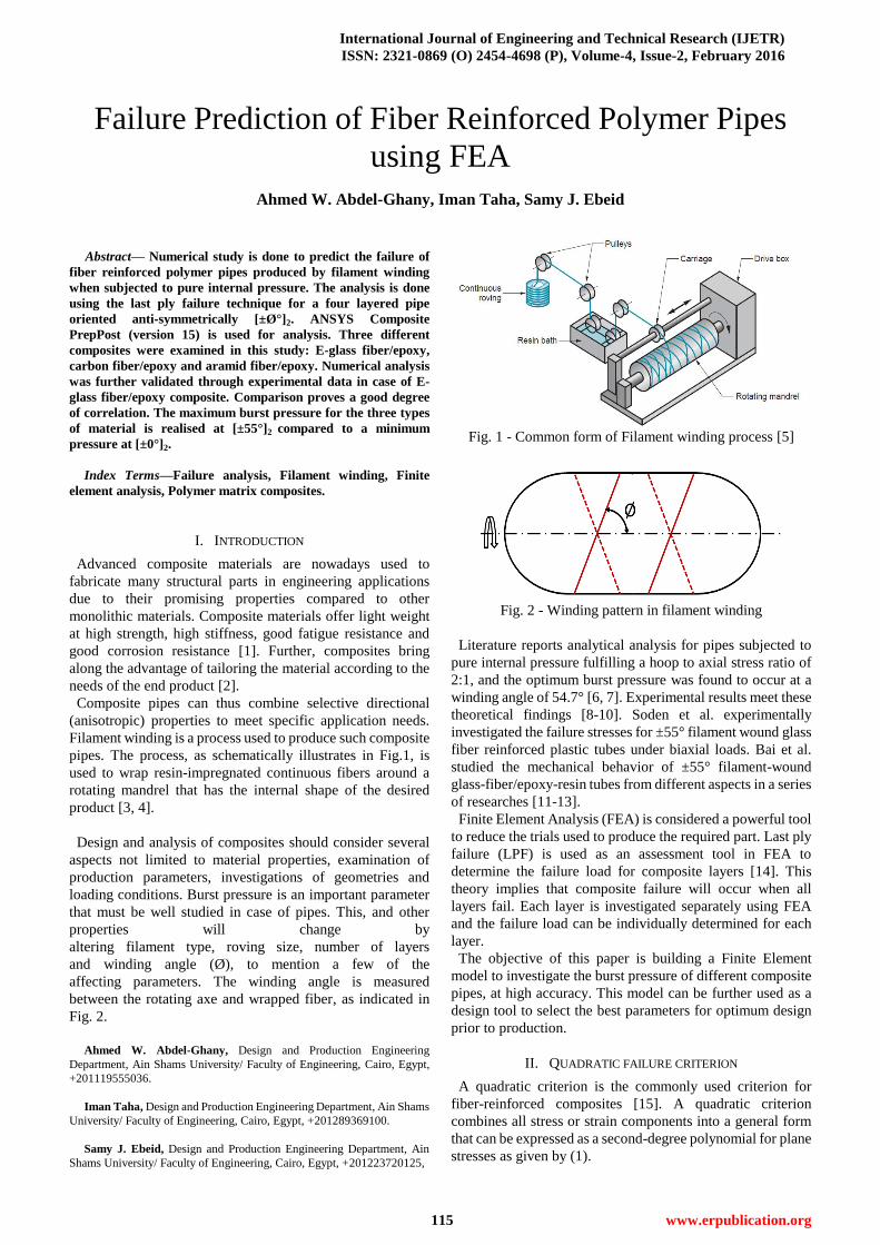
affecting parameters. The winding angle is measured
between the rotating axe and wrapped fiber, as indicated in
Fig. 2.
Ahmed W. Abdel-Ghany, Design and Production Engineering
Department, Ain Shams University/ Faculty of Engineering, Cairo, Egypt,
+201119555036.
Iman Taha, Design and Production Engineering Department, Ain Shams
University/ Faculty of Engineering, Cairo, Egypt, +201289369100.
Samy J. Ebeid, Design and Production Engineering Department, Ain
Shams University/ Faculty of Engineering, Cairo, Egypt, +201223720125,
Fig. 1 - Common form of Filament winding process [5]
Fig. 2 - Winding pattern in filament winding
Literature reports analytical analysis for pipes subjected to
pure internal pressure fulfilling a hoop to axial stress ratio of
2:1, and the optimum burst pressure was found to occur at a
winding angle of 54.7° [6, 7]. Experimental results meet these
theoretical findings [8-10]. Soden et al. experimentally
investigated the failure stresses for ±55° filament wound glass
fiber reinforced plastic tubes under biaxial loads. Bai et al.
studied the mechanical behavior of ±55° filament-wound
glass-fiber/epoxy-resin tubes from different aspects in a series
of researches [11-13].
Finite Element Analysis (FEA) is considered a powerful tool
to reduce the trials used to produce the required part. Last ply
failure (LPF) is used as an assessment tool in FEA to
determine the failure load for composite layers [14]. This
theory implies that composite failure will occur when all
layers fail. Each layer is investigated separately using FEA
and the failure load can be individually determined for each
layer.
The objective of this paper is building a Finite Element
model to investigate the burst pressure of different composite
pipes, at high accuracy. This model can be further used as a
design tool to select the best parameters for optimum design
prior to production.
II. QUADRATIC FAILURE CRITERION
A quadratic criterion is the commonly used criterion for
fiber-reinforced composites [15]. A quadratic criterion
combines all stress or strain components into a general form
that can be expressed as a second-degree polynomial for plane
stresses as given by (1).
Failure Prediction of Fiber Reinforced Polymer Pipes
using FEA
Ahmed W. Abdel-Ghany, Iman Taha, Samy J. Ebeid

Failure Prediction of Fiber Reinforced Polymer Pipes using FEA
116 www.erpublication.org
2 2 2
11 1 22 2 66 12 12 1 2 1 1 2 22
f
F F F F F F
(1)
Xt and Xc denote the tensile and compressive strengths in the
direction of fiber, Yt and Yc are the tensile and compressive
strengths transverse to fiber direction and S is the shear
strength in the same plane. The coefficients F11, F22, F66, F1,
and F2 present material strength in the principle material
directions. These coefficients and F12 can be determined in
various ways, based on the following theories.
A. Tsai Wu failure criterion
11
1
t c
FX X
, 1
1 1
t c
FX X
, 22
1
t c
FYY
,
(2)
2
1 1
t c
FY Y
, 66 2
1F
S ,
122 , 1F XY default Therefore Tsai-Wu criterion can be written as:
2 2 2
1 2 121 22
1 2
1 1 1 1
t c t c
t c t c
fX X YY S
X X Y Y
(3)
B. Tsai Hill failure criterion:
11 2
1F
X , 1 0F , 22 2
1F
Y , 2 0F ,
(4)
12 2
1
2F
X , 66 2
1F
S
X and Y are defined as follow:
1 0 X=Xt ; 1 0 X=Xc
(5)
2 0 Y=Yt ; 2 0 Y=Yc
Therefore Tsai-Hill criterion can be written as:
2 2 2 2
1 2 12 1 2
2 f
X Y S X
(6)
C. Hoffman failure criterion:
11
1
t c
FX X
, 1
1
t c
FX X
, 22
1
t c
FYY
,
(7)
2
1
t c
FY Y
, 12
1
t c
FX X
, 66 2
1F
S
Therefore Tsai-Hill criterion can be written as:
2 2 2
1 2 12 1 2 1 2
2
t c t c t c t c t c
fX X YY S X X X X YY
(8)
III. FINITE ELEMENT ANALYSIS
A. Model building
A mechanical model of the pipe is built in ANSYS
Composite PrepPost (ACP) with the dimensions shown in
Table 1 [8]. The geometry of the pipe is defined using shell
geometry in the ACP. Quadratic shell element (SHELL281),
as illustrated in Fig. 3 is selected for the analysis.
The mesh generated on the shell geometry is further shown
in Fig. 4. To simulate the hydraulic burst failure test, fixed
supports are applied at both pipe ends. Pressure is applied to
the internal pipe wall, as schematically presented in Fig. 5.
Table 1: Dimensions of the pipe
Length of the pipe 400 mm
Internal diameter of pipe 100 mm
Wall thickness of pipe 1.6 mm
Approximate Thickness of each layer 0.4 mm
Fig. 3 - Shell element
Fig. 4 - Generated shell element for a four layered pipe
Fig. 5 - Loading conditions and constrains
E-glass fiber/epoxy material is defined in the model using
the literature data summarized in Table 2 [8]. Four
anti-symmetrical layers are applied to the geometry [±Ø°]2.
The default fiber direction (0° orientation) is defined parallel

International Journal of Engineering and Technical Research (IJETR)
ISSN: 2321-0869 (O) 2454-4698 (P), Volume-4, Issue-2, February 2016
117 www.erpublication.org
to the pipe axis, which is also the mandrel axis of rotation as
well as the reference line from which the winding angle is
measured (Fig. 6). Different winding angles are used for
simulation: [±45°]2, [±55°]2, [±60°]2, [±75°]2 and [±90°]2, as
indicated in Fig. 7.
Table 2: Properties of E-glass Fiber/Epoxy
Property E-glass
Fiber/Epoxy
Young's
Modulus
Ex (GPa) 36.5
Ey = Ez (GPa) 15
Poisson's
Ratio
Vxy = Vxz 0.24
Vyz 0.22
Shear
Modulus
Gxy = Gxz (GPa) 6.35
Gyz (GPa) 1.6
Tensile
Strength
Xt (MPa) 1050
Yt = Zt (MPa) 43
Compression
Strength
Xc (MPa) -938
Yc = Zc (MPa) -106
Shear
Strength
Sxy = Syz = Sxz
(MPa) 88
Fig. 6 - Reference direction for fibers
B. Numerical analysis
The element size directly affects FEA results. A coarse
element will give the advantage of reduced solving time but
with lack of accuracy, and vice versa for the fine elements.
Using the concept of the LPF, the burst pressure will be
determined for each individual ply. A randomly selected
pressure value is applied as an initial load, where the Reserve
Factor (RF) is determined for each ply individually. The
Reserve Factor (RF) is used to determine the margin to
failure, where the failure load is equal to the applied load
multiplied by the RF. In other words, if RF is greater than one
the applied load is low and needs to be increased to cause
failure, and vice versa.
(a)
(b)
Fig. 7 - Fiber orientation for (a) [±55°]2 and (b) [±90°]2
Fig. 8 - Flow chart for the Finite Element Analysis using Last
Ply Failure
The failure pressure is then determined using (9), where
Pfailure is the failure load and Papplied is the applied load. This is
equivalent to the minimum pressure required to cause a failure
in all plies of the pipe (burst pressure).
failure appliedP P RF (9)
Hence, to apply LPF, all RF must be slightly less than or
equal to one. Otherwise a higher value for pressure is selected
and the test is run again until this condition is satisfied. The
flow chart given in Fig. 8 shows the various stages of the
analysis.
Several trials are conducted using the ACP Analysis to
determine the optimum number and size of elements. The
predicted burst pressure is compared to the experimental
value known for an E-glass/epoxy pipe manufactured at 55°
winding angle [±55°]2.
Fig. 9 – Burst Pressure vs. number of elements for pure
internal pressure of E-glass/epoxy pipe with [±55°]2 winding
angle

Failure Prediction of Fiber Reinforced Polymer Pipes using FEA
118 www.erpublication.org
Fig. 9 presents the effect of element number on the predicted
burst pressure. It can be observed that the burst pressure
increases with increasing number of elements, up to an
element number of about 5000, after which results start to
stabilize at a constant pressure of 10.9 MPa. Based on these
results, an element size of 5 mm (approximately 5200
elements) will be sufficient for predicting the burst pressure
with an acceptable percent of error at a reasonable
computational cost.
Finally the simulated results are compared to experimental
values.
IV. NUMERICAL RESULTS
A. Model Verification
Three theories were used to compare numerical and
experimental results, namely the Tsai-Wu, Tsai-Hill and
Hoffman theories. Fig. (10-12) show the results of these
analyses in contrast to the experimental data for a glass
fiber/epoxy pipe produced by filament winding.
Fig. 10 - Comparative analysis between experimental results
and Tsai-Wu failure criterion for [±Ø°]2 E-glass fibers/epoxy
orthotropic tubes
Fig. 11 - Comparative analysis between experimental results
and Tsai-Hill failure criterion for [±Ø°]2 E-glass fibers/epoxy
orthotropic tubes
Results of the three criterions used are very close to
the experimental outcomes. Whereas both Tsai-Hill
and Hoffmann models seem to slightly underestimate
the burst pressure (but still within the acceptable range
of error), Tsai-Wu was found to be most fitting to the
experimental results.
Maximum burst pressure occurs at 55° winding angle
as theoretically predicted at a pressure of 10.9 MPa
for using Tsai-Wu, 11.2 MPa for using Tsai-Hill and
10.6 MPa for using Hoffman theory, in contrast to an
experimental value of 11.18 MPa. Fig, 13 shows the
expected burst pressure for the range of winding
angles from [±0°]2 to [±45°]2 which are not
experimentally proven. The results confirm that the
55° winding angle provides the optimum setup. The
[±0°]2 layup shows the lowest burst pressure record for
all anti-symmetrical layups.
Fig. 12 - Comparative analysis between experimental results
and Hoffman failure criterion for [±Ø°]2 E-glass fibers/epoxy
orthotropic tubes
Fig. 13 - FEA results for variation of burst pressure with
different winding angle for [±Ø°]2 E-glass fiber/epoxy
orthotropic tubes
B. Analysis of carbon fiber/epoxy and aramid/epoxy pipes
Proving good agreement with experimental data, the
same FEA model is adopted for the analysis of
different composites. Carbon fiber/epoxy and
aramid/epoxy are selected for this analysis.
Table 3 shows the respective properties used in the
FEA [16-19]. The burst pressure is predicted for the
following set of plies [±0°]2, [±30°]2, [±45°]2, [±55°]2,
[±60°]2, [±75°]2, and [±90°]2.
Analysis results of the burst pressure for pipes made
of carbon fiber/epoxy composites at different winding
angles using the various failure criterions are shown in
Fig. 14. Maximum burst pressure occurs at [±55°]2

International Journal of Engineering and Technical Research (IJETR)
ISSN: 2321-0869 (O) 2454-4698 (P), Volume-4, Issue-2, February 2016
119 www.erpublication.org
with a pressure of 29.4 MPa for Tsai-Wu criterion,
28.8 MPa for Tsai-Hill and 27.1 MPa for Hoffman.
The minimum burst pressure occurs at [±0°]2 with a
value of 0.93 MPa for both Tsai-Hill and Hoffman
criterion compared with 0.95 MPa for Tsai-Wu.
Table 3: Properties of carbon fiber/epoxy and aramid
fiber/epoxy composites
Property Carbon
Fiber/Epoxy
Aramid
/Epoxy
Young's
Modulus
Ex (GPa) 127.7 83
Ey = Ez (GPa) 7.4 7
Poisson's
Ratio
Vxy = Vxz 0.33 0.41
Vyz 0.188 0.4
Shear
Modulus
Gxy = Gxz (GPa) 6.9 2.1
Gyz (GPa) 4.3 1.86
Tensile
Strength
Xt (MPa) 1717 1377
Yt = Zt (MPa) 30 18
Compression
Strength
Xc (MPa) -1200 -235
Yc = Zc (MPa) -216 -53
Shear
Strength
Sxy = Syz = Sxz
(MPa) 33 34
Fig. 14 - FEA results for variation of burst pressure with
different winding angle for [±Ø°]2 carbon fiber/epoxy
orthotropic tubes
Fig. 15 - FEA results for variation of burst pressure with
different winding angle for [±Ø°]2 aramid fiber/epoxy
orthotropic tubes
Fig. 15 shows the same analysis for aramid/epoxy,
recording maximum burst pressure at [±55°]2 with a value of
25.5 MPa for Tsai-Wu criterion, 20 MPa for Hoffman
criterion and 18 MPa for Tsai-Hill criterion. The minimum
burst pressure was recorded to be about 0.6 MPa for the
three criterions at [±0°]2. As a result the optimum winding
angle is [±55°]2 verified for the three criterions. A
Comparison of the analytical results using the Tsai-Wu
criterion for E-glass/epoxy, carbon/epoxy and aramid/epoxy
is shown in Fig. 16. FEA records show that carbon/epoxy
pipes withstand maximum burst pressure through the
variation of winding angle, followed by aramid/epoxy and
finally E-glass/epoxy. Except for the range of winding
angles from [±0°]2 to [±42°]2 aramid/epoxy shows higher
resistance to pressure. Comparative analysis for the
maximum induced Von-Mises stress just before failure for
the three materials shown in Fig. 17.
Fig. 16 - Comparing numerical burst pressure for different
composite structures through different [±Ø°]2
Fig. 17 - Comparing numerical equivalent stresses just before
failure for different composite structures through different
[±Ø°]2
V. DISCUSSION AND CONCLUSIONS
This study was done to simulate the structural behavior of
composite pipes subjected to internal pressure. Analysis for
E-glass/epoxy applying LPF technique and Tsai-Wu, Tsai-

Failure Prediction of Fiber Reinforced Polymer Pipes using FEA
120 www.erpublication.org
Hill and Hoffman failure criterions shows close prediction
for the burst pressure compared to the experimental results.
FEA prediction of the burst pressure for a four layered
filament wound composite pipes made of E-glass/epoxy,
carbon/epoxy and aramid/epoxy composites using LPF
concept concluded that the optimum winding angle is 55°.
The lowest burst pressure was recorded to be at 0° winding
angle. The burst pressure at the optimum winding angle
[±55°]2 for the three materials E-glass/epoxy, aramid/epoxy
and carbon/epoxy is predicted to be 10.9, 25.5
and 29.4 MPa respectively; where the burst Pressure for
Carbon/epoxy is about three times that for E-glass/epoxy.
The burst pressure for [±0°]2 comparing the three
composites is almost the same. For [±90°]2, carbon/epoxy
and aramid/epoxy results to about double the burst pressure
for E-glass/epoxy.
REFERENCES
[1] S. Mazumdar, Composites manufacturing: materials, product, and
process engineering: CrC press, 2001.
[2] A. Newberry, "GRP pipe: custom or commodity?," Reinforced
Plastics, vol. 47, pp. 22-24, 2003.
[3] S. T. Peters, Composite filament winding: ASM International, 2011.
[4] F. C. Shen, "A filament-wound structure technology overview,"
Materials Chemistry and Physics, vol. 42, pp. 96-100, 1995.
[5] M. P. Groover, Fundamentals of modern manufacturing: materials
processes, and systems: John Wiley & Sons, 2007.
[6] J. Evans and A. Gibson, "Composite angle ply laminates and netting
analysis," in Proceedings of the Royal Society of London A:
Mathematical, Physical and Engineering Sciences, 2002, pp.
3079-3088.
[7] S. Sulaiman, S. Borazjani, and S. Tang, "Finite element analysis of
filament-wound composite pressure vessel under internal pressure,"
in IOP Conference Series: Materials Science and Engineering, 2013,
p. 012061.
[8] A. Onder, O. Sayman, T. Dogan, and N. Tarakcioglu, "Burst failure
load of composite pressure vessels," Composite structures, vol. 89,
pp. 159-166, 2009.
[9] M. Shultz and L. Smith, "Optimal fiber orientation for fiber reinforced
pressure vessels," in Proceedings of the SEM X International
Congress & Exposition on Experimental & Applied Mechanics,
Costa Mesa, California, USA, June, 2004, pp. 7-10.
[10] B. Spencer and D. Hull, "Effect of winding angle on the failure of
filament wound pipe," Composites, vol. 9, pp. 263-271, 1978.
[11] J. Bai, P. Seeleuthner, and P. Bompard, "Mechanical behaviour
of±55° filament-wound glass-fibre/epoxy-resin tubes: I.
Microstructural analyses, mechanical behaviour and damage
mechanisms of composite tubes under pure tensile loading, pure
internal pressure, and combined loading," Composites science and
technology, vol. 57, pp. 141-153, 1997.
[12] J. Bai, G. Hu, and P. Bompard, "Mechanical behaviour of±55
filament-wound glass-fibre/epoxy-resin tubes: II. Micromechanical
model of damage initiation and the competition between different
mechanisms," Composites science and technology, vol. 57, pp.
155-164, 1997.
[13] G. Hu, J. Bai, E. Demianouchko, and P. Bompard, "Mechanical
behaviour of±55° filament-wound glass-fibre/epoxy-resin tubes—III.
Macromechanical model of the macroscopic behaviour of tubular
structures with damage and failure envelope prediction," Composites
science and technology, vol. 58, pp. 19-29, 1998.
[14] N. Rahimi, A. K. Hussain, M. S. Meon, and J. Mahmud, "Capability
assessment of finite element software in predicting the last ply failure
of composite laminates," Procedia Engineering, vol. 41, pp.
1647-1653, 2012.
[15] I. ANSYS, "ANSYS Composite PrepPost User's Guide," ed, 2013.
[16] S. W. Tsai, Theory of composites design: Think composites Dayton,
1992.
[17] M. Al-Khalil and P. Soden, "Theoretical through-thickness elastic
constants for filament-wound tubes," International journal of
mechanical sciences, vol. 36, pp. 49-62, 1994.
[18] J. Lifshitz and H. Dayan, "Filament-wound pressure vessel with thick
metal liner," Composite Structures, vol. 32, pp. 313-323, 1995.
[19] A. Hamed, M. Hamdan, B. Sahari, and S. Sapuan, "Experimental
characterization of filament wound glass/epoxy and carbon/epoxy
composite materials," ARPN Journal of Engineering and Applied
Sciences, vol. 3, pp. 76-87, 2008.
Ahmed W. Abdel-Ghany, B.Sc. is a teaching
assistant at the ―Design and Production
Engineering‖ Department of Ain Shams University
in Cairo – Egypt. His current research interests are
in the areas of composite materials, stress analysis,
and modeling and simulation of mechanical systems
using FEA. Ahmed W. Abdel-Ghany has worked for
three years in the Technical Research and
Development Department, Egyptian Air Forces.
Iman Taha, Ph.D is an Associate Professor at the
―Design and Production Engineering‖ Department
of the Ain Shams University in Cairo – Egypt. The
main research interests lie in the field of polymers
and polymer composites, their development,
processing and characterization technologies. Iman
Taha has above 20 international publications,
covering the above mentioned field, especially in
combination with renewable resources.
Samy J. Ebeid, Ph.D is an Emeritus Professor at
the ―Design and Production Engineering‖
Department of Ain Shams University in Cairo –
Egypt. The main research interests lie in the fields of
Recent Manufacturing Processes
(ECM – EDM – LASER – RP …etc), Machine
Design and Stress Analysis. Samy J. Ebeid has
above 50 local and international publications
covering the mentioned fields. Samy J. Ebeid is also
a referee for international journals in addition was a
member of the Egyptian scientific committee for the
promotion of professors and a member of the
Egyptian national committee for welding
technology.