F L Y M - pudn.comread.pudn.com/downloads126/ebook/534816/McGraw Hill - W-CDMA a… · Chapter 6...
401
TEAMFLY
Transcript of F L Y M - pudn.comread.pudn.com/downloads126/ebook/534816/McGraw Hill - W-CDMA a… · Chapter 6...

TEAMFLY
Team-Fly®

W-CDMA and
cdma2000 for3G Mobile Networks
M.R. Karimand
M. Sarraf
McGraw-HillNew York Chicago San Francisco Lisbon
London Madrid Mexico City Milan New DelhiSan Juan Seoul Singapore Sydney Toronto

Copyright © 2002 by M.R. Karim and Lucent Technologies, Inc.0-07 All rights reserved. Manufactured in the United States of America.Except as permitted under the United States Copyright Act of 1976, no part of this publication may be reproduced or distributed in anyform or by any means, or stored in a database or retrieval system, without the prior written permission of the publisher.
0-07-140956-4
The material in this eBook also appears in the print version of this title:0-07-138513-4.
All trademarks are trademarks of their respective owners. Rather than put a trademark symbol after every occurrence of a trade-marked name, we use names in an editorial fashion only, and to the benefit of the trademark owner, with no intention of infringe-ment of the trademark. Where such designations appear in this book, they have been printed with initial caps.
McGraw-Hill eBooks are available at special quantity discounts to use as premiums and sales promotions, or for use in corporatetraining programs. For more information, please contact George Hoare, Special Sales, at [email protected] or (212)904-4069.
TERMS OF USEThis is a copyrighted work and The McGraw-Hill Companies, Inc. (“McGraw-Hill”) and its licensors reserve all rights in and to thework. Use of this work is subject to these terms. Except as permitted under the Copyright Act of 1976 and the right to store andretrieve one copy of the work, you may not decompile, disassemble, reverse engineer, reproduce, modify, create derivative worksbased upon, transmit, distribute, disseminate, sell, publish or sublicense the work or any part of it without McGraw-Hill’s prior con-sent. You may use the work for your own noncommercial and personal use; any other use of the work is strictly prohibited. Yourright to use the work may be terminated if you fail to comply with these terms.
THE WORK IS PROVIDED “AS IS”. McGRAW-HILL AND ITS LICENSORS MAKE NO GUARANTEES OR WARRANTIESAS TO THE ACCURACY, ADEQUACY OR COMPLETENESS OF OR RESULTS TO BE OBTAINED FROM USING THEWORK, INCLUDING ANY INFORMATION THAT CAN BE ACCESSED THROUGH THE WORK VIA HYPERLINK OROTHERWISE, AND EXPRESSLY DISCLAIM ANY WARRANTY, EXPRESS OR IMPLIED, INCLUDING BUT NOT LIMITEDTO IMPLIED WARRANTIES OF MERCHANTABILITY OR FITNESS FOR A PARTICULAR PURPOSE. McGraw-Hill and itslicensors do not warrant or guarantee that the functions contained in the work will meet your requirements or that its operation willbe uninterrupted or error free. Neither McGraw-Hill nor its licensors shall be liable to you or anyone else for any inaccuracy, erroror omission, regardless of cause, in the work or for any damages resulting therefrom. McGraw-Hill has no responsibility for the con-tent of any information accessed through the work. Under no circumstances shall McGraw-Hill and/or its licensors be liable for anyindirect, incidental, special, punitive, consequential or similar damages that result from the use of or inability to use the work, evenif any of them has been advised of the possibility of such damages. This limitation of liability shall apply to any claim or cause what-soever whether such claim or cause arises in contract, tort or otherwise.
DOI: 10.1036/0071409564
abcMcGraw-Hill
iii
To our families
Rahima, Razi, and Nayeem—MRK
Maryam, Artin, and Shawhin—MS
ABOUT THE AUTHORS
M. R. Karim, formerly a Distinguished Member of Technical Staff of BellLaboratories, was a member of the original team that developed the world’sfirst cellular system. He has published in the areas of mobile communica-tions and packet switching, and is author of the book ATM Technology andServices Delivery (Prentice Hall, 1999).
Mohsen Sarraf received his Ph.D. degree in 1986 from the University ofSouthern California. He joined Bell Laboratories in 1987 where he hasbeen involved in various aspects of communications systems. He hasworked on wireless systems from design and implementation to projectleadership during the last ten years. Currently he is the Director ofAdvanced Multimedia Communications Department of Bell Labs.
Copyright 2002 M.R. Karim and Lucent Technologies. Click Here for Terms of Use.
CONTENTS
Preface xi
Acknowledgments xiii
Foreword xv
Chapter 1 Introduction 1
Early Systems 2
The Cellular System 4
TDMA System 9
IS-54 and IS-136 9
GSM 11
cdmaOne (Based on IS-95-A and IS-95-B) 13
Personal Communications System 15
Third-Generation (3G) Wireless Technology 16
3G Requirements 18
Evolution to 3G Systems 21
Summary 23
References 25
Chapter 2 Propagation Characteristics of a Mobile Radio Channel 27
Large-Scale Variations 29
Signal Variations in Free Space 29
Variations in Urban Areas Due to Terrain and Clutter 31
Signal Variations in Suburban and Rural Areas 35
Variation of the Local Mean Signal Level 36
Propagation Model 39
Short-term Variations of the Signal 41
Effect of Short-term Variations 45
Coherence Bandwidth and Power Delay Profiles 46
Simulation Model of a Mobile Radio Channel 49
Summary 52
References 52
Chapter 3 Principles of Wideband CDMA (WCDMA) 55
Multiple Access Schemes 56
FDMA 57
TDMA 58
Spread Spectrum Multiple Access 59
Copyright 2002 M.R. Karim and Lucent Technologies. Click Here for Terms of Use.
For more information about this book, click here.
CDMA Technology 60
Direct-Spread CDMA Principles 60
Capacity of a CDMA System 63
3G Radio Transmitter Functions 67
Speech Encoding 69
Channel Coding 71
Convolutional Encoder 71
Decoding Convolutional Codes 76
Punctured Codes 76
Channel Encoders for UMTS 76
Interleavers 78
Modulation 79
Demodulation of a Phase Modulated Signal 80
Spreading 82
Walsh Codes 82
Scrambling Codes 83
Receiver 90
Receiver Structure 90
Hard and Soft Decision 91
Viterbi Decoding 93
Multipath Diversity in CDMA 94
Rake Receiver 95
Multiuser Detection 98
Smart Antennas 101
Summary 106
Appendix A—Viterbi Decoding
of Convolutional Codes 107
Appendix B—Modulation 110
QPSK 110
Offset QPSK (OQPSK) 111
Differential QPSK (DQPSK) 111
Appendix C—Multiuser Detection Using Viterbi Algorithm 113
References 116
Chapter 4 cdmaOne and cdma2000 121
cdmaOne 122
Spectrum Allocation 122
Physical Channels 123
Reverse Channel Transmit Functions 124
Forward Channel Functions 127
Contentsvi
Power Control 130
Handoff in IS-95 133
cdma2000 137
System Features 137
The Protocol Stack 140
Physical Channels 143
Forward Channel Transmit Functions 146
Reverse Channel Transmit Functions 147
Summary 149
References 151
Chapter 5 The GSM System and General Packet Radio Service (GPRS) 153
GSM System Features 155
System Architecture 157
Speech Encoder 162
Channel Encoder 163
Interleaving 165
Modulation Technique—GMSK 166
Logical Channels 169
GSM Frame and Slot Structure 171
Data Services in GSM 173
General Capabilities and Features of GPRS 174
GPRS Network Architecture 175
GPRS Protocol Stacks 177
Packet Structures 180
Logical Channels 181
Packet Transmission Protocol 182
Summary 186
References 187
Chapter 6 Universal Mobile Telecommunications System (UMTS) 189
System Features 190
Wireless Network Architecture 193
Radio Interface Protocol Stack—An Overview 195
Physical Layer 198
Overview of Physical Layer Functions 199
Transport Channels 203
Physical Channels 206
Packet Mode Data 214
Mapping of Transport Channels to Physical Channels 215
Contents vii

Physical Layer Procedures 215
Spreading and Modulation 223
Physical Layer Measurements 230
MAC Layer Protocol 232
Overview 232
MAC Procedures 234
MAC Layer Data Formats 236
Radio Link Control Protocol 237
RLC Functions 237
RLC Protocol Description 240
Packet Data Convergence Protocol (PDCP) 245
Overview 245
Header Compression 246
Broadcast/Multicast (BMC) Protocol 246
Radio Resource Control Protocol 247
RRC Functions 247
Management of RRC Connections 249
Handover 250
Summary 254
References 256
General Systems Descriptions 256
Overview of the UE-UTRAN Protocols 256
Physical Layer 257
Layer 2 and Layer 3 Protocols 257
Protocols at Different Interface Points 257
Miscellaneous Specifications of Interest 258
Other References 259
Web Sites 259
Chapter 7 Evolution of Mobile Communication Networks 261
Review of 3G Requirements [1]-[4] 262
Network Evolution 264
First-Generation Network 264
Second-Generation Networks 266
2G� Networks 268
3G Network 270
All-IP Network 271
Summary 273
References 274
Contentsviii

Chapter 8 Call Controls and Mobility Management 277
Protocol Stacks in Access and Core Networks 279
GSM 279
UMTS 282
Call Controls 291
Summary 295
References 296
Chapter 9 Quality of Service (QoS) in 3G Systems 297
Introduction 298
Overview of the Concepts 300
Classification of Traffic 301
UMTS Service Attributes 304
Requesting QoS—RSVP Protocol 309
Admission Control 315
Admission Control Strategies 315
Resource Allocation 317
Policing 318
Providing Requested QoS 320
Differentiated Services (DiffServ) 323
RSVP for Mobile Systems 325
Summary 329
References 329
Chapter 10 Network Planning and Design 331
Network Design 334
Spectrum Requirements 334
Link Budget Calculation 337
Frequency Planning 343
Analog and TDMA Systems 343
CDMA System 347
Cellular System Growth 347
Cell Splitting 348
Overlay Design 348
Summary 351
Appendix A—Traffic Capacity of a Network 351
References 352
Contents ix

Chapter 11 Beyond 3G 355
Driving Force Behind 4G 356
Applications and Features of 4G 358
Technologies 360
Other Considerations 361
References 362
Appendix List of Abbreviations and Acronyms 363
Index 375
Contentsx
TEAMFLY
Team-Fly®
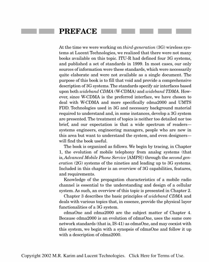
PREFACE
At the time we were working on third-generation (3G) wireless sys-tems at Lucent Technologies, we realized that there were not manybooks available on this topic. ITU-R had defined four 3G systems,and published a set of standards in 1999. In most cases, our onlysources of information were these standards, which were necessarilyquite elaborate and were not available as a single document. Thepurpose of this book is to fill that void and provide a comprehensivedescription of 3G systems. The standards specify air interfaces basedupon both wideband CDMA (W-CDMA) and wideband TDMA. How-ever, since W-CDMA is the preferred interface, we have chosen todeal with W-CDMA and more specifically cdma2000 and UMTSFDD. Technologies used in 3G and necessary background materialrequired to understand and, in some instances, develop a 3G systemare presented. The treatment of topics is neither too detailed nor toobrief, and our expectation is that a wide spectrum of readers—systems engineers, engineering managers, people who are new inthis area but want to understand the system, and even designers—will find the book useful.
The book is organized as follows. We begin by tracing, in Chapter1, the evolution of mobile telephony from analog systems (that is, Advanced Mobile Phone Service [AMPS]) through the second gen-eration (2G) systems of the nineties and leading up to 3G systems.Included in this chapter is an overview of 3G capabilities, features,and requirements.
Knowledge of the propagation characteristics of a mobile radiochannel is essential to the understanding and design of a cellularsystem. As such, an overview of this topic is presented in Chapter 2.
Chapter 3 describes the basic principles of wideband CDMA anddeals with various topics that, in essence, provide the physical layerfunctionalities of a 3G system.
cdmaOne and cdma2000 are the subject matter of Chapter 4.Because cdma2000 is an evolution of cdmaOne, uses the same corenetwork standards (that is, IS-41) as cdmaOne, and may coexist withthis system, we begin with a synopsis of cdmaOne and follow it upwith a description of cdma2000.
Copyright 2002 M.R. Karim and Lucent Technologies. Click Here for Terms of Use.

Chapter 5 is devoted to GSM and General Packet Radio Service(GPRS). The reasons we have included these two systems are the fol-lowing: Both GSM and UMTS share the same core network and usethe same Mobile Application Part (MAP) protocol of Signaling Sys-tem 7. Similarly, the packet mode data services in UMTS and theassociated network entities and protocols have been harmonizedwith those of GPRS. Thus, even though there are significant differ-ences in the air interface standards of UMTS Terrestrial RadioAccess Network (UTRAN) and GSM, a description of GSM and GPRSmay be helpful to the reader in this context.
UMTS is described in Chapter 6, where, among other things, wediscuss the protocols of different layers, synchronization schemes,power controls, and handover procedures.
Since packet mode data is an important aspect of 3G, existing corenetworks, which are built around a circuit-switch fabric, work in con-junction with routers and gateways to provide packet mode data ser-vices. In fact, because of high volume data transfer requirements innext generation systems, the core network is evolving to an all-IParchitecture. Chapter 7 describes the evolution of mobile communi-cation networks.
Chapter 8 touches briefly on call controls and mobility manage-ment in wireless networks. To help the reader understand this topicbetter, a brief description of protocol stacks at various interfacepoints is also included.
Chapter 9 deals with the quality of service (QoS) concepts as theyrelate to 3G, provides the reader with a basic understanding of thesubject, and discusses the need for implementing a flexible resourcemanagement scheme in the network that will provide mobile sta-tions with an end-to-end QoS across all-IP networks.
Network planning and design issues, such as spectrum require-ments, link budget calculation, frequency planning, and cellulargrowth, are presented in Chapter 10.
We conclude the book with our reflections, in Chapter 11, on whatmay come about beyond 3G, discuss the driving force behind the evo-lution of the fourth-generation (4G) system, and mention some tech-nologies that might play a key role in the development of 4G.
Prefacexii
ACKNOWLEDGMENTSThe authors would like to thank Reed Fisher who read almost theentire manuscript, and gave us valuable comments. Special thanksgo to Ken Smolik who gladly reviewed much of the material andoffered suggestions that have greatly enhanced the quality of thebook. Thanks are also due to Nikil Jayant, Victor Lawrence, and ananonymous reviewer for going over a few chapters and giving ustheir comments. We are grateful to Marjorie Spencer for inviting usto write this book and for her continued interest in this endeavor.Finally, we would like to express our most sincere gratitude to ourfamilies because without their constant support and encouragement,we could not have undertaken this work and completed it on time.
M. R. KARIM
M. SARRAF
MARCH 2002
Copyright 2002 M.R. Karim and Lucent Technologies. Click Here for Terms of Use.

This page intentionally left blank.
FOREWORD
Throughout history and across boundaries, people have been engaged ina constant quest for information. What they have learned is that infor-mation is one of the most valuable and enabling commodities in the world.Those who have it become more powerful, and those who can access itfaster than others gain an extra edge. For this reason, people are con-stantly in search of means to generate, archive, access, and transfer infor-mation as quickly as possible. This quest for obtaining and transferringinformation has made people innovate in many dimensions. It has madethem create new words, new means of recording information, new meansof interpreting information, and, above all, new means of transmittinginformation. In the latter area, over the past several thousand years wehave observed the use of smoke signals and the creation and evolution oflanguages, mail systems, messenger services, the telegraph, wirelessbroadcast, telephony, wireless telephony, and now e-mail and wirelessmessages. Among important parameters in this quest are the amount, thetype, the speed, the security, and the ease of access of the underlying infor-mation to be transferred.
As with many other scientific and technological quests, the advances incommunications have come in cycles of slower progress in the beginninguntil a critical mass has been achieved, followed by a leap and the contin-uation of the cycle. Eventually, these leaps will take the technology to thepoint where the underlying service (be it agricultural, medical, engineer-ing, scientific, or another type of service) will become inexpensive and reli-able enough to make it economically viable for mass production, resultingin a big jump in quality of life. We are fortunate to live at a point in his-tory that allows us to observe the many technological advances in infor-mation transfer taking place right in front of our eyes. Never before havewe been able to transfer information of most types (text, image, sound)fast and securely enough for real-time applications, from anywhere toanywhere with portable gadgets light and small enough to fit easily in ourpockets. Only a couple of decades ago, this achievement would have beenrelegated to science fiction writers and movie producers. The aforemen-tioned scientific and technological leaps, however, have swiftly moved theachievement from imagination to implementation. To make implementa-tions cheap and, at the same time, ubiquitous, those involved in bringingthis technology to the public have created the Third Generation WirelessTelephony standards, commonly referred to as 3G.
Copyright 2002 M.R. Karim and Lucent Technologies. Click Here for Terms of Use.

Forewordxvi
Those who produce and implement 3G solutions will provide the pub-lic with great social and economic benefits. Learning about the basics ofthe technologies and methods upon which 3G solutions are based is thefirst step in this important task, and this book is an excellent vehicle toaccomplish that step. With a depth that is just right for graduate stu-dents, engineers who are developing the systems, and others who want tograsp the breadth of the subject, it describes the most important issues inthe design of the overall 3G system. (It is also suitable for business man-agers, product managers, sales and marketing, attorneys, and others whoneed to gain general knowledge of the subject.) At the same time, it eas-ily accommodates the more advanced readers, who can use it to pinpointthe important issues in the field and follow up on them in the moreadvanced literature cited in its references. Some of the issues discussed inthis book are the challenges of the wireless channel, the evolution of theolder technologies to the current ones, the basics of the Code DivisionMultiple Access (CDMA) technology, systems planning, and the architec-ture of the systems and their evolution. All are presented in a highly read-able manner, providing a great all-inclusive source for learning andreferences on the subject of 3G wireless technology.
I hope every reader enjoys and takes advantage of this book, as I did.
VICTOR B. LAWRENCE
VICE PRESIDENT
ADVANCED COMMUNICATIONS TECHNOLOGY
BELL LABORATORIES—LUCENT TECHNOLOGIES

Introduction
CHAPTER 11
Copyright 2002 M.R. Karim and Lucent Technologies. Click Here for Terms of Use.

Early SystemsThe earliest recorded instance of radio service to moving vehicles,such as ships, trains, and automobiles, was an experimental systemin 1919 that provided two-way radio communication among coastalsteamers between Boston and Baltimore [2], [3]. For the next 12years or so, considerable improvement was made to radio communi-cations technology to provide an effective high-seas mobile radio ser-vice. For land-based users, however, the earliest mobile phone servicewas in 1933, although research laboratories started experimentingwith it much earlier. This system used a 35 MHz frequency band andwas available only to police and fire departments.There were only 10channels in the system with a 40 kHz spacing. It was a manual sys-tem where channel assignment and dialing were performed by thetelephone operator. Because the mobile could not receive and trans-mit information simultaneously, the user had to “push to talk.” Therewas no roaming feature available. In other words, users wouldreceive service only in their registered home areas and would bedenied the service if they moved to different serving areas.
Subsequently, in 1946, the FCC granted some spectrum on the 150MHz band for an improved mobile telephone service; that year, fol-lowing this spectrum allocation, the first commercial service wasintroduced in St. Louis, Missouri, and by the end of the same year,services were available to 25 other U.S. cities. These earlier systemswere manual in that all calls were handled by a telephone operator.Because of the heavy demand for this service, the FCC allocated sixmore channels around 150 MHz and 12 new channels around 450MHz in 1956. This is the first time that a 450 MHz system was usedfor commercial service [1].
An improved version of the mobile telephone service was intro-duced in 1964. Known as the MJ, this system operated at 150 MHzand had 11 channels. Initially, the channel spacing was 120 kHz, butwith the advancement of radio frequency (RF) circuit technology, thisspacing was reduced to 30 kHz with a peak frequency deviation of 5kHz. Each mobile serving area consisted of a single, fixed-tuned FMtransmitter, which was located centrally at a high enough elevationso that it could serve all mobiles in the serving area with a high
Chapter 12
probability. The RF power output of a transmitter was 50 to 250 W,while with the antenna gain, the radiated power at the antenna wasusually in the range of 500 W. A number of FM receivers were placedat different points in the serving area to receive the signal from allvehicles. These transmitters and receivers were then connected to acontrol terminal in a local switch. Roaming features were now pro-vided. However, because the complete routing information was notavailable to the local switch, a land-originated call to a roamingmobile had to be completed manually by telephone operators. Themobile unit could scan all available channels, lock onto an idle one,and then start dialing. Signaling was done using low-frequencyaudio tones.The maximum range between a serving transmitter anda mobile unit was about 25 miles. To provide satisfactory operation,frequencies could be reused but only at distances of 75 miles or more.
To meet the growing demand from customers, the FCC opened upanother spectrum in the 450 MHz band. This system, which wasintroduced in 1969, was known as the MK system and had 12 chan-nels with a frequency spacing of 25 kHz. Like its predecessor, it sup-ported automatic dialing and operator-assisted roaming.
These early systems provided three types of mobile telephone ser-vice:
� Complete Mobile Telephone Service (MTS) for voicecommunication to land-mobile users assisted with mobiletelephone operators where necessary.
� Automatic Dispatch Service (ADS) was used between one ormore dispatchers and a fleet of mobile units. This servicesupported only one two-way conversation at a time between adispatcher and a mobile unit. Conference calls between adispatcher and multiple mobile units were not possible.
� One-way paging.
The spectrum allocated by the FCC for these early systems wasusually quite small compared to the relatively large number of con-tending users. Also, because of the limitations of the hardware tech-nology, the frequencies could not be reused at distances any closerthan 75 miles or so. Thus, naturally, as the demand grew, users expe-rienced high probability of call blockage. To overcome this
3Introduction

fundamental problem, the FCC set aside a bandwidth of 75 MHz inthe 850 MHz range and asked common carriers to submit their pro-posals for a high-capacity mobile telecommunication system(HCMTS) [1]. In response, the Bell System submitted comprehensivedetails of one such system based on the cellular concept that hadbeen under development in Bell Laboratories since 1947 [4]. Finally,in 1974, the FCC ruled that 40 MHz of the original 75 MHz spectrumcould be used by common carriers to provide advanced mobile tele-phone service, and the remaining 30 MHz was reserved for privateservices. In 1975, the Illinois Bell Telephone Company filed a peti-tion to the FCC asking for permission to build and test a cellular sys-tem. The permission was granted in 1977. Consequently, in 1978, adevelopment system that was built in Bell Laboratories during 1972to 1977 was installed in Chicago to verify the system concept anddesign issues. This phase of the trial, known as the Equipment Test,involved only 100 mobile units. A follow-up test phase, known as theService Test, was launched in the following years using about 2,000mobile units that were designed by outside vendors1 according toBell Laboratories specifications.
The Cellular SystemThe FCC allocated a bandwidth of 20 MHz—from 870 to 890 MHz—in the forward direction (that is, from base station transceivers tomobile stations) and another band of 20 MHz—from 825 MHz to 845MHz—in the reverse direction.2 These frequency bands were dividedinto a number of channels, each with a bandwidth of 30 kHz. Theoperating frequencies of these channels are shown in Figure 1-1.
The idea behind a cellular system is simple [22]. Because the spac-ing between adjacent channels is 30 kHz, there are altogether 666channels in either direction. Of these channels, a few are set aside for
Chapter 14
1They were Motorola and E. F. Johnson of the United States and Oki of Japan.2Because a different frequency band is used for transmission in each direction, thesystem is said to operate in a frequency division duplex (FDD) mode.
TEAMFLY
Team-Fly®

access and control purposes, while the rest are used as voice chan-nels to provide two-way voice communications. Because each user isassigned a different channel operating at a different frequency, thesystem is called frequency division multiple access (FDMA).
In the simplest case, the desired serving area is partitioned into anumber of hexagonal cells of equal size. A base station may belocated at the center of each hexagonal cell and provide coverage onthe entire cell using an omnidirectional antenna. Alternatively, abase station may be located at each alternate corner of a cell andcover each of the three 120-degree sectors of the cell using a direc-tional antenna. The actual radius of each cell depends upon a num-ber of parameters, one of which is the traffic density. The availablevoice channels are divided into seven sets3 in such a way that the
5Introduction
f870.045870.015
o o oCh. 1 Ch 2 Ch 666
889.965 MHz
f
o o oCh 2 Ch 666Ch 1
825.015 825.045 844.965
Upstream (Mobile to Base Station)
Downstream (Base Station to Mobile)
MHz
∆
∆
Figure 1-1Spectrumallocation andchannelassignment inadvanced mobilephone service
3Here the available channels have been divided into seven sets, assuming a cluster ofseven cells.As will be shown shortly, the channels could have been divided differently,leading to a different cluster size. For example, clusters of 3, 4, 9, 12, and so on couldbe used. However, the cluster size of seven has some advantages. They will be dis-cussed later.

separation between any two neighboring channels in any set is aslarge as possible so that the adjacent channel interference becomesminimum. Each channel set is assigned to one of a cluster of sevencells as depicted in Figure 1-2 and reused in other cells outside thecluster over and over again as shown in Figure 1-3, where each cellis identified by the number of the channel set being used in that cell.Cells that use the same channel set are called co-channel cells. Inthis example, the cluster consists of seven cells. Thus, the co-channelreuse ratio is 7.
To see how the channel sets should be reused, refer once more toFigure 1-3. From the center of a cell, say, cell 2, we go across two cellsalong vector OA as indicated by i � 2 and then one cell along vectorAB as indicated by j � 1. The cell where we finally land is the co-channel cell with channel set 2. Clearly, for any given cell, there areexactly six co-channel cells. In a general case, for any value of i andj, the distance D between any two neighboring co-channel cells isgiven by
(1-1)
In terms of the radius of a cell R
(1-2)D>R � 231i2 � ij � j 2 2
D � 2i2 � ij � j 2
Chapter 16
ChannelSet (CS) 1
CS 5
CS 3
CS 2CS 4
CS 7
CS 6
Figure 1-2Available channelsassigned to acluster of sevencells
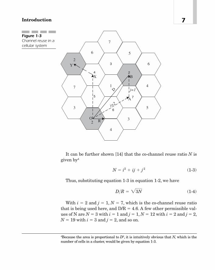
It can be further shown [14] that the co-channel reuse ratio N isgiven by4
(1-3)
Thus, substituting equation 1-3 in equation 1-2, we have
(1-4)
With i � 2 and j � 1, N � 7, which is the co-channel reuse ratiothat is being used here, and D/R � 4.6. A few other permissible val-ues of N are N � 3 with i � 1 and j � 1, N � 12 with i � 2 and j � 2,N � 19 with i � 3 and j � 2, and so on.
D>R � 23N
N � i2 � ij � j 2
7Introduction
1
5
3
24
7
6
5
6
2
4
2
7
3
4
3
5
6
7
R
D
O
A
BX
Y
i=2
j=1
Figure 1-3Channel reuse in acellular system
4Because the area is proportional to D2, it is intuitively obvious that N, which is thenumber of cells in a cluster, would be given by equation 1-3.

The interference experienced by a mobile station from its neigh-boring co-channel cells is called co-channel interference. The signal-to-co-channel interference at a mobile station depends upon theco-channel reuse ratio and the path loss characteristics of the RFsignal.5
The mobile phone system that was developed in Bell Laboratoriesusing the cellular concept was called Advanced Mobile Phone Service(AMPS). It was first commercially deployed by Ameritech in Chicagoin 1983. This system, which was subsequently standardized as TIA-553, was based on essentially the same technical specifications anddesign principles as the development system of the trial phase andused the 40 MHz spectrum allocation.
Later in 1989, the FCC allocated another 10 MHz band. Thus, atotal bandwidth of 50 MHz was now available for cellular systems.The spectrum allocation is shown in Figure 1-4. The B bands con-sisting of subbands B and B¿ were provided for use by wire-line ser-vice providers such as AT&T, MCI, Verizon, and so on. The A bandsconsisting of A, A¿ and A– were opened to nonwireline serviceproviders. With a channel spacing of 30 kHz, the number of chan-nels available in either direction is 833. System features are sum-marized in Table 1-1. The parameters of the table will be discussedlater.
Chapter 18
5Assume that the received signal strength varies inversely as the nth power of thedistance, that is, S � k/dn, where k is a constant and d is the distance. If the mobileis at the edge of its serving cell, the interference to the mobile due to a co-channelcell at a distance D from the mobile is given by I � k/Dn. Because there are six co-channel cells, the signal-to-interference ratio (SIR) at the mobile is given by
Here, all base stations are assumed to havethe same transmitter power level and antenna gain, among other things. Theexponent n depends on the terrain and environmental clutter and may vary from2 to 5. Assuming n � 3.5 and N � 7 for a cluster of seven cells, S/I � 34.33 or 15.36dB. The previous expression for the SIR shows that the larger the value of N, thegreater the SIR. However, a disadvantage of a large value of N is that now, for agiven spectrum allocation, each channel set has fewer channels. As a result, thecapacity of a cell (that is, the number of active calls per cell) is diminished. In mostcases of spectrum allocation, N � 7 gives a fairly good SIR.
S>I � 1 kRn 2> 16k
Dn 2 � 16 1DR 2n � 1
6 13N 2n>2.

TDMA System
IS-54 and IS-136
In Cellular System TIA-553, where each user is allocated one physi-cal channel with a bandwidth of 30 kHz, about 21 channels arereserved for access and paging, and the remaining 811 are reservedfor voice channels. Thus, in a cellular system with a co-channel reuseratio of 7, each cell has 116 channels (that is, 811/3) or about 39 chan-nels (that is, 116/3) per sector.
Because of the tremendous demand for cellular services, it wassoon found that there was a need to increase the capacity of an exist-ing system, or alternatively build new systems with higher capacity.The capacity of an installed system could be increased with the
9Introduction
824
A" A B A' B' B'A'BAA"
849 869 894MHz
1 MHz 10 MHz 10 MHz 1.5 MHz 2.5 MHz 2.5 MHz1.5 MHz10 MHz10 MHz1 MHz
Mobiles Base Station Base Station Mobiles
Figure 1-4The spectrumallocation by theFCC for commercialdeployment ofcellular systems
Multiple Access Scheme FDMA with FDD
Channel Bandwidth 30 kHz
No. of Users per Channel 1
Speech Signal Analog, band-limited to 300—3000 Hz
Data Rate 10 kb/s (only for control)
Modulation FM for speech, FSK for data
Frequency Deviation 12 kHz for speech and 8 kHz for data
User Data Transfer Capability None
Table 1-1
The cellularsystem features
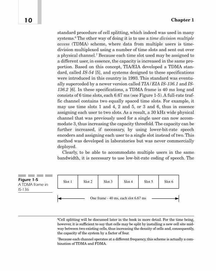
standard procedure of cell splitting, which indeed was used in manysystems.6 The other way of doing it is to use a time division multipleaccess (TDMA) scheme, where data from multiple users is time-division multiplexed using a number of time slots and sent out overa physical channel.7 Because each time slot used may be assigned toa different user, in essence, the capacity is increased in the same pro-portion. Based on this concept, TIA/EIA developed a TDMA stan-dard, called IS-54 [5], and systems designed to these specificationswere introduced in this country in 1993. This standard was eventu-ally superceded by a newer version called TIA/EIA IS-136.1 and IS-136.2 [6]. In these specifications, a TDMA frame is 40 ms long andconsists of 6 time slots, each 6.67 ms (see Figure 1-5). A full-rate traf-fic channel contains two equally spaced time slots. For example, itmay use time slots 1 and 4, 2 and 5, or 3 and 6, thus in essenceassigning each user to two slots. As a result, a 30 kHz wide physicalchannel that was previously used for a single user can now accom-modate 3, thus increasing the capacity threefold. The capacity can befurther increased, if necessary, by using lower-bit-rate speechencoders and assigning each user to a single slot instead of two. Thismethod was developed in laboratories but was never commerciallydeployed.
Clearly, to be able to accommodate multiple users in the samebandwidth, it is necessary to use low-bit-rate coding of speech. The
Chapter 110
6Cell splitting will be discussed later in the book in more detail. For the time being,however, it is sufficient to say that cells may be split by installing a new cell site mid-way between two existing cells, thus increasing the density of cells and, consequently,the capacity of the system by a factor of four.7Because each channel operates at a different frequency, this scheme is actually a com-bination of TDMA and FDMA.
Slot 1
One frame - 40 ms, each slot 6.67 ms
Slot 2 Slot 3 Slot 4 Slot 5 Slot 6Figure 1-5A TDMA frame inIS-136

System features are summarized in Table 1-2. Obviously, in thesedigital systems, it is possible to multiplex user data with digitallyencoded speech, thus opening up the possibility of providing data ser-vices (both basic and enhanced, such as mobile access to the Inter-net), which would be outside the realm of the older analog systems.
GSM
In Europe, cellular mobile telephony was first introduced in Swe-den, Norway, Finland, and Denmark in 1981. These were all analogsystems operating at 450 and 900 MHz bands. Over the next fewyears, many large service providers, such as Nordic Mobile Tele-phone (NMT) and Total Access Communications Systems (TACS),installed similar systems in almost every other country of WesternEurope. One of the problems with these systems was that theywere incompatible with each other and thus did not permit
11Introduction
Multiple Access Scheme TDMA
Spectrum Allocation 824—849 MHz uplink
869—894 MHz Downlink
Channel Bandwidth 30 kHz
Modulation Data Rate on 48.6 kb/san RF Channel
Modulation �/4-Shifted DQPSK
No. of Users per Channel 3 for full-rate speech and 6 for half-rate.There are 6 time slots/frame.
Digital Coding of Speech Vector Sum Excited Linear Predictive(VSELP) coder at 7.95 kb/s with 159 bits per20 ms frame
Channel Coding Combination of 7-bit CRC and convolutionalcoding of rate 1/2
User Data Transfer Capability Limited capability, such as short messages ona dedicated control channel (DCCH)
Table 1-2
The IS-136 systemfeatures

inter-system or international roaming. To overcome this problem, anew standard called Global System for Mobile Communications(GSM) was developed in 1990 for next-generation digital cellularmobile communications in Europe. Systems based on this standardwere first deployed in 18 European countries in 1991. By the end of1993, it was adopted in nine more countries of Europe, as well asAustralia, Hong Kong, much of Asia, South America, and now theUnited States.
GSM, like IS-54 and IS-136, combines FDMA and TDMA accessschemes and uses 2 frequency bands around 900 MHz [7]. As shownin Figure 1-6, the first band, dedicated to the reverse link, operatesat 890 to 915 MHz and the second at 935 to 960 MHz on the forwardlink. Each physical channel has a bandwidth of 200 kHz and consistsof 8 time slots, each assigned to an individual user. Among the fea-tures supported by the system are the following:
� Voice, call forwarding, call screening, and call hold.
� Facsimile.
� Short messaging service (SMS).
� Circuit-switched data services at rates up to 12 kb/s. The systemcan support a maximum of 76.8 kb/s data rate by bundling 8transport channels.
� International roaming.
� Interoperability with ISDN.
� Discontinuous transmissions of mobile stations, thus leading toincreased battery life.
In addition to the standard voice telephony, call forwarding, andcall screening, the system supports transmission of digital data inthe range of 0.3 to 9.6 kb/s transparently using the normal channelcoding procedure of the system as well as nontransparently using
Chapter 112
915
Downlink
890 935 960
UplinkFrequency (MHz)
Figure 1-6The spectrumallocation in theGSM system

special coding procedures as required by a user interface. In GSM,a TDMA frame is 4.615 ms long and consists of 8 time slots, eachassigned to a user. Thus, the effective bandwidth per user is only25 kHz (that is, 200/8). Other features include SMS, in whichalphanumeric texts of limited lengths are transmitted by base sta-tions along with the regular voice traffic and such supplementaryISDN services as caller identification, call diversion, and so on. Thesystem features are summarized in Table 1-3.
cdmaOne (Based on IS-95-A and IS-95-B)Concurrently, the application of spread spectrum technology to amobile communication system was being explored. The feasibility ofsuch a system based on code division multiple access (CDMA)scheme was demonstrated in 1998. According to this scheme, each
13Introduction
Multiple Access Scheme TDMA
Spectrum Allocation 890—915 MHz uplink
935—960 MHz Downlink
Channel Bandwidth 200 kHz
Modulation Data Rate on 270.8333 kb/san RF Channel
Modulation 0.3 GMSK
No. of Users per Channel 8 for full-rate speech
Digital Coding of Speech Regular Pulse Excitation with Long-TermPredictor (RPE-LTP) at 13 kb/s for full-ratecoding
Channel Coding Combination of block coding and convolu-tional coding
User Data Transfer Capability Circuit-switched data up to 12 kb/s and SMS
Table 1-3
GSM systemfeatures

user is assigned a unique pseudonoise (PN) code whose clock rate(that is, the chip rate) is generally much higher than the user datarate. The PN code modulates the user data and the resulting outputphase-modulates a carrier. The available spectrum is divided into anumber of channels, each with a much higher bandwidth—1.25 MHz—compared to the TDMA systems that were previously discussed.However, the same carrier can now be used in all cells, adjacent orotherwise, and not just in those cells that are outside a cluster as inthe cellular or GSM system. In other words, the co-channel reuseratio is 1. It was found that CDMA systems can provide much largercapacity, more efficient utilization of the spectrum, better speechquality using low-bit-rate linear predictive coders, more robust com-munication of data services employing efficient channel coding, andmuch larger bandwidth per channel, thus leading to the possibility,for the first time, of truly multimedia services in wireless networks.With more efficient and dynamic power controls and novel trans-mission algorithms, transmitter power requirements for the basestation or even the mobile station can be minimized. Thus, the hand-sets could be smaller and more compact in design, resulting inincreased battery life. Furthermore, handoff strategies used in aCDMA system provide for a better coverage and lead to an improve-ment in the system performance. Because of these potential benefitsthat the system may eventually offer to the end users, this new tech-nology is fast becoming popular. In the United States, there is nowthe CDMA system called cdmaOne based on TIA/EIA specificationsIS-95A and IS-95B at Cellular 850 and PCS 1800 MHz bands [8].Table 1-4 lists the basic features of this system.
Chapter 114
Multiple Access Scheme CDMA, FDD
Spectrum Allocation Cellular CDMA:824—849 MHz uplink and869—894 MHz downlink
PCS CDMA:1850—1910 MHz uplink1930—1990 MHz downlink
Table 1-4
cdmaOne systemfeatures
TEAMFLY
Team-Fly®
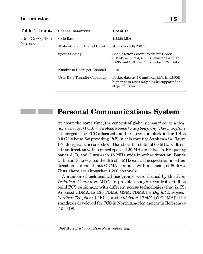
Personal Communications SystemAt about the same time, the concept of global personal communica-tions services (PCS)—wireless access to anybody, anywhere, anytime—emerged. The FCC allocated another spectrum block in the 1.8 to2.0 GHz band for providing PCS in this country. As shown in Figure1-7, the spectrum consists of 6 bands with a total of 60 MHz width ineither direction with a guard space of 20 MHz in between. Frequencybands A, B, and C are each 15 MHz wide in either direction. BandsD, E, and F have a bandwidth of 5 MHz each. The spectrum in eitherdirection is divided into CDMA channels with a spacing of 50 kHz.Thus, there are altogether 1,200 channels.
A number of technical ad hoc groups were formed by the JointTechnical Committee (JTC) to provide enough technical detail tobuild PCS equipment with different access technologies (that is, IS-95-based CDMA, IS-136 TDMA, GSM, TDMA for Digital EuropeanCordless Telephone [DECT] and wideband CDMA [W-CDMA]). Thestandards developed for PCS in North America appear in References[15]–[19].
15Introduction
Channel Bandwidth 1.23 MHz
Chip Rate 1.2288 Mb/s
Modulation (for Digital Data) QPSK and OQPSK8
Speech Coding Code Excited Linear Predictive Coder(CELP)—1.2, 2.4, 4.8, 9.6 kb/s for Cellular IS-95 and CELP—14.4 kb/s for PCS IS-95
Number of Users per Channel �16
User Data Transfer Capability Packet data at 9.6 and 14.4 kb/s. In IS-95B,higher data rates may also be supported insteps of 8 kb/s.
Table 1-4 cont.
cdmaOne systemfeatures
8OQPSK is offset quadrature phase shift keying.
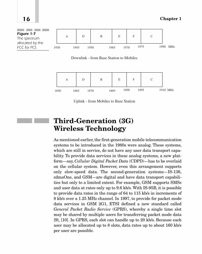
Third-Generation (3G) Wireless TechnologyAs mentioned earlier, the first-generation mobile telecommunicationsystems to be introduced in the 1980s were analog. These systems,which are still in service, do not have any user data transport capa-bility. To provide data services in these analog systems, a new plat-form—say, Cellular Digital Packet Data (CDPD)—has to be overlaidon the cellular system. However, even this arrangement supportsonly slow-speed data. The second-generation systems—IS-136,cdmaOne, and GSM—are digital and have data transport capabili-ties but only to a limited extent. For example, GSM supports SMSsand user data at rates only up to 9.6 kb/s. With IS-95B, it is possibleto provide data rates in the range of 64 to 115 kb/s in increments of8 kb/s over a 1.25 MHz channel. In 1997, to provide for packet modedata services in GSM 2G1, ETSI defined a new standard calledGeneral Packet Radio Service (GPRS), whereby a single time slotmay be shared by multiple users for transferring packet mode data[9], [10]. In GPRS, each slot can handle up to 20 kb/s. Because eachuser may be allocated up to 8 slots, data rates up to about 160 kb/sper user are possible.
Chapter 116
1945
A B
MHz
Downlink - from Base Station to Mobiles
Uplink - from Mobiles to Base Station
1930 1950 1965 1970 1975 1990
CD E F
1865
A B
MHz1850 1870 1885 1890 1895 1910
CD E F
Figure 1-7The spectrumallocated by theFCC for PCS
To support high-speed data rates and, more importantly, to be ableto provide for multimedia services, the International Telecommuni-cations Union-Radio Communication Sector (ITU-R) undertook thetask of defining a set of recommendations for International MobileTelecommunication in the year 2000 (IMT-2000). Reference [21] givesa historical background on the standardization activities thatresulted in the development of many different proposals for 3G radiointerfaces and eventually culminated in the selection of a few basictechnologies. Briefly, research organizations, equipment manufac-turers, and service providers from many different countries of theworld started working on different aspects of 3G mobile communi-cations. They developed algorithms and air interfaces, performedsimulation, built prototypes, and conducted field tests to verify theirvalidity. 3G partnership projects were established to coordinate thetechnical activities of various groups and help work out their details.Based on their work, a number of regional standards bodies began todevelop the relevant standards. They were
� Telecommunications Industry Association (TIA) and T1P1 in theUnited States. Here, two proposals emerged. One, from TIATR45.5, is cdma2000. Based upon the direct sequence spreadspectrum technology, cdma2000 works in the FDD mode,operates with one or more carriers, and is backwards compatiblewith the 2G system cdmaOne.
The other proposal, from TR45.3, is UWC-136, which iswideband TDMA based on recommendations from the UniversalWireless Communications Consortium (UWCC) that developedthe TDMA standard IS-136 for the United States.
� The Association of Radio Industries and Business (ARIB) ofJapan. Initially, this organization made a number of proposals,based on W-CDMA, TDMA, and even Orthogonal FrequencyDivision Multiplexing (OFDM) schemes. At the end of theprocess, however, it submitted only one proposal to ITU that isbased on W-CDMA.
� European Telecommunications Standards Institute(ETSI)/Special Mobile Group (SMG). Here also a number ofproposals were initially studied. Eventually, only two proposalswere submitted. One is Universal Mobile Telecommunications
17Introduction

System (UMTS) W-CDMA FDD, which was actually harmonizedwith the ARIB proposal. The other is UMTS, based on time-division, code-division multiple access (TD-CDMA) principles 17and operates in the TDD mode.9
� Telecommunications Technology Association (TTA) of SouthKorea. Here two proposals were developed—one of them wassimilar to cdma2000, and the other was similar to theETSI/ARIB proposal.
Thus, eventually, there were only 4 systems for 3G mobile com-munications—cdma2000, UWC-136, W-CDMA UMTS FDD, and W-CDMA UMTS TDD. Recommendations on these systems werepublished by ITU-R as a harmonized standard with four modes in1999. cdma2000 is required to comply with EIA/TIA IS-41 and W-CDMA UMTS with GSM MAP intersystem networking standards.ITU-R also stipulated that IMT-2000 might provide for other modesas necessary in support of systems that may be developed from timeto time around the world with new spectrum allocation.
3G Requirements
3G systems are required to operate in many different radio environ-ments, such as indoor or outdoor, urban, suburban, or rural. The endusers may be fixed or moving at various speeds. For example, ser-vices may involve:
� Stationary users or pedestrian (0 to 10 km/h)
� Ordinary vehicular applications up to 100 km/h
� High-speed vehicular applications up to 500 km/h
� Aeronautical applications up to 1500 km/h
� Satellites up to 27000 km/h.
Chapter 118
9In TDD, the same carrier frequency is used in either direction. Information is trans-mitted in frames, each consisting of a number of time slots, some of which are used foruplink transmissions and the rest for downlink.

The infrastructure used to deliver 3G services may be either ter-restrial or satellite based.The information types may include speech,audio, data, text, image, and video [11]. Radio interfaces must bedesigned to provide voiceband data and variable bit rate services toend users. Both circuit and packet mode data must be supported.The data rates may be
� 144 kb/s or more in vehicular operations10
� At least 384 kb/s for pedestrians
� About 2.048 Mb/s for indoor or low-range outdoor applications
Many different cell sizes are permissible in 3G. For example, theycould be
� Large or so-called megacells more than 35 km in radius
� Macrocells with a radius of 1 to 35 km
� Indoor or outdoor microcells with a radius of up to 1 km
� Indoor or outdoor picocells with a radius of less than 50 m
3G networks must interoperate with legacy networks, such as aPublic Switched Telephone Network (PSTN) or Integrated ServicesDigital Network (ISDN) [12], as well as packet-switched public datanetworks, for example, the Internet.
Some user applications may require bandwidth on demand and aguaranteed quality of service (QoS) from networks. Thus, the corenetwork should be capable of reserving resources based on userrequests and making sure that all users get the requested quality.3G standards call for efficient utilization of the spectrum and, insome cases, phased introduction of these services [13]. For example,the data rate supported may be only 144 kb/s in the first phase, 384kb/s in the second phase, and 2.048 Mb/s in the final phase, allphases being backwards compatible. The goal here is to provide 3Gservices to users regardless of their locations, in both rural andurban areas, and to support both national and international roamingin a seamless manner. Mobile stations should be able to interwork
19Introduction
10It is understood that the system must also be capable of supporting lower data rates(such as 14.4 kb/s, 64 kb/s, and so on) as well.

with different multimedia terminal types that may be used on thefixed side and also connect to other mobile users over satellite linksif necessary.Additional services, such as user identity, global positionidentification, and so on, may also be offered to a customer as avail-able options [12]. Mobile stations could be in different sizes. Forexample, they could be as small as a pocket radio or large enough torequire mounting in a vehicle, and should be able to operate satis-factorily in extreme weather conditions. Open interfaces should beused wherever possible. The service quality to be provided to mobileusers is intended to be comparable to that available from a PSTN oran ISDN and should be maintained even when there is more thanone service provider in a given serving area [13]. The received speechquality at a mobile station should be equivalent to 32 kb/s adaptivedifferential pulse code modulation (ADPCM). Services should beprovided to each user with an acceptable degree of privacy and secu-rity that would be at least as good as or better than what is currentlyavailable over a PSTN. Finally, the 3G networks should be synergis-tic with the architecture of the future network.
The 3G standards envisage different types of user traffic. Forexample, it may be
� Constant bit rate traffic, such as speech, high-quality audio,video telephony, full-motion video, and so on, which are sensitiveto delays and, more importantly, delay variations.
� Real-time variable bit rate traffic, such as variable bit-rateencoded audio, interactive MPEG video, and so on. This type oftraffic requires variable bandwidths and is also sensitive todelays and delay variations.
� Non-real-time variable bit rate traffic, such as interactive andlarge file transfers, that can tolerate delays or delay variations.
Some possible applications that appear commercially attractiveare
� Conversational voice, video phone and video conferencing,interactive games, and two-way process control, and telemetryinformation.
� High-speed Internet access applications, such as web browsing,e-mail, data transfer to or from a server (such as a database
Chapter 120

download for later analysis), transaction services (that is,e-commerce), and so on.
� Audio streaming, one-way video, still images, large-volume datatransfers, and telemetering information for monitoring purposesat an operations and maintenance center.
� Entertainment-quality audio.
� Inquiries/reservation (such as, plane ticket ordering and so on.
Evolution to 3G Systems
One of the goals of 3G standards is to enable the graceful evolutionof the current, 2G wireless networks, using as much of the existinginfrastructure as possible. The evolution path to 3G is shown in Fig-ure 1-8.
cdma2000 is actually an evolution of cdmaOne. As indicatedbefore, it is a direct sequence spread spectrum system, may use oneor more carriers, and operates in the FDD mode. In a multicarrier
21Introduction
IS-136
GSM 2G+GPRS
GSM (2G)UMTS
WCDMA
GSM 2G++GPRS/EDGE
IS-136 HS, Outdoor
IS-136+IS-136 HS
Indoor
IS-95 cdma2000Figure 1-8The evolution pathto 3G systems

system with N carriers (N � 1, 2, or 3), each individual carrier usu-ally has a bandwidth of 1.25 MHz. However, for N � 3, the totalbandwidth required is 5 MHz, including the necessary guard bands.To provide for high-speed data services, say, up to 2 Mb/s, a singlecarrier may have a nominal bandwidth of 5 MHz11 with a chip rateof 3.6864 Mc/s (that is, 3 � 1.2288 Mc/s). Commercial viability mayrequire the cdma2000 technology to be introduced in differentphases. For example, phase 1 may use a single carrier that will sup-port data rates up to 144 kb/s. In phase 2, two more carriers may beadded to provide still higher data rates.
Standards have been designed to harmonize core networks ofUMTS with those of GSM. Similarly, packet mode data services ofUMTS have been harmonized with GPRS, which is a service capa-bility of GSM 2G1. W-CDMA, which is the radio interface of theUMTS Terrestrial Radio Access (UTRA), uses a direct sequencespread spectrum on a 5 MHz bandwidth and operates in both FDDand TDD modes.
The TDMA version of the 3G system for use in North America isknown as UWC-136.As shown in Figure 1-8, its evolution takes placein three phases: IS-1361, IS-136 HS Outdoor/Vehicular, and IS-136HS Indoor. The first phase, IS-1361, provides voice and up to 64 kb/sdata.The per-channel bandwidth is still the same (that is, 30 kHz) asfor IS-136. However, to support higher data rates, 8-PSK modulationis used instead of the usual QPSK. The second phase provides datarates up to 384 kb/s for outdoor/vehicular operations, using high-levelmodulation and a bandwidth of 200 kHz per channel. It should bementioned here that ETSI has defined a standard called EnhancedData Rates for GSM Evolution (EDGE) to support IP-based servicesin GSM at rates up to 384 kb/s [20], [21]. IS-136 HS for outdoor/vehic-ular applications is designed to use this standard in the access net-work. In the third stage, IS-136 HS Indoor, end users may have adata rate of up to 2 Mb/s with a bandwidth of 1.6 MHz.The spectrumallocation for UWC-136 is the same as for cdma2000.
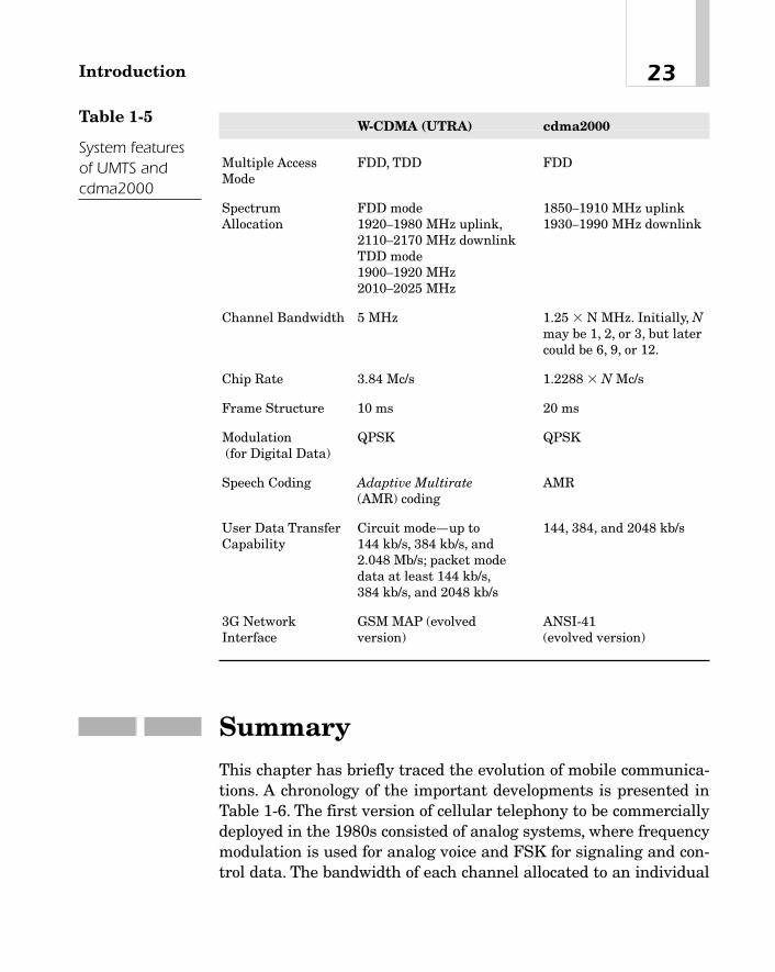
The system features of UMTS and cdma2000 are summarized inTable 1-5.
Chapter 122
11Or, if necessary, the bandwidth of a single carrier may be some multiple of 5 MHz.
SummaryThis chapter has briefly traced the evolution of mobile communica-tions. A chronology of the important developments is presented inTable 1-6. The first version of cellular telephony to be commerciallydeployed in the 1980s consisted of analog systems, where frequencymodulation is used for analog voice and FSK for signaling and con-trol data. The bandwidth of each channel allocated to an individual
23Introduction
W-CDMA (UTRA) cdma2000
Multiple Access FDD, TDD FDDMode
Spectrum FDD mode 1850—1910 MHz uplinkAllocation 1920—1980 MHz uplink, 1930—1990 MHz downlink
2110—2170 MHz downlinkTDD mode1900—1920 MHz2010—2025 MHz
Channel Bandwidth 5 MHz 1.25 � N MHz. Initially, Nmay be 1, 2, or 3, but latercould be 6, 9, or 12.
Chip Rate 3.84 Mc/s 1.2288 � N Mc/s
Frame Structure 10 ms 20 ms
Modulation QPSK QPSK(for Digital Data)
Speech Coding Adaptive Multirate AMR(AMR) coding
User Data Transfer Circuit mode—up to 144, 384, and 2048 kb/sCapability 144 kb/s, 384 kb/s, and
2.048 Mb/s; packet mode data at least 144 kb/s,384 kb/s, and 2048 kb/s
3G Network GSM MAP (evolved ANSI-41 Interface version) (evolved version)
Table 1-5
System featuresof UMTS andcdma2000
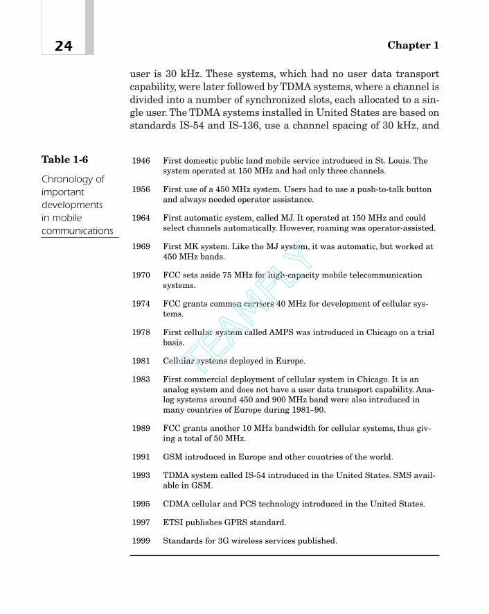
user is 30 kHz. These systems, which had no user data transportcapability, were later followed by TDMA systems, where a channel isdivided into a number of synchronized slots, each allocated to a sin-gle user. The TDMA systems installed in United States are based onstandards IS-54 and IS-136, use a channel spacing of 30 kHz, and
Chapter 124
1946 First domestic public land mobile service introduced in St. Louis. Thesystem operated at 150 MHz and had only three channels.
1956 First use of a 450 MHz system. Users had to use a push-to-talk buttonand always needed operator assistance.
1964 First automatic system, called MJ. It operated at 150 MHz and couldselect channels automatically. However, roaming was operator-assisted.
1969 First MK system. Like the MJ system, it was automatic, but worked at450 MHz bands.
1970 FCC sets aside 75 MHz for high-capacity mobile telecommunicationsystems.
1974 FCC grants common carriers 40 MHz for development of cellular sys-tems.
1978 First cellular system called AMPS was introduced in Chicago on a trialbasis.
1981 Cellular systems deployed in Europe.
1983 First commercial deployment of cellular system in Chicago. It is ananalog system and does not have a user data transport capability. Ana-log systems around 450 and 900 MHz band were also introduced inmany countries of Europe during 1981—90.
1989 FCC grants another 10 MHz bandwidth for cellular systems, thus giv-ing a total of 50 MHz.
1991 GSM introduced in Europe and other countries of the world.
1993 TDMA system called IS-54 introduced in the United States. SMS avail-able in GSM.
1995 CDMA cellular and PCS technology introduced in the United States.
1997 ETSI publishes GPRS standard.
1999 Standards for 3G wireless services published.
Table 1-6
Chronology ofimportantdevelopments in mobilecommunications
TEAMFLY
Team-Fly®

provide six slots per frame, eventually tripling the capacity com-pared to the older analog system. GSM, which is used in much ofEurope and many other countries of the world, is also based on theTDMA technology, where each channel has a bandwidth of 200 kHz,and each frame consists of six slots.A distinctive feature of these sys-tems is their support of SMS and circuit-switched user data. Anenhanced data service called GPRS is also now available in GSM.CDMA systems, which use direct sequence spread spectrum tech-nology, have been deployed in this country since 1995. Standards for3G wireless services were published in 1999. Support for high-speeddata at rates from 144 kb/s for urban and suburban outdoor envi-ronments to 2,048 Mb/s for indoor or low-range outdoor environ-ments is one of the most important features of 3G. Because of themany advantages that it offers, the CDMA technology forms thebasis of 3G systems.
References[1] W.R. Young, “Advanced Mobile Phone Service: Introduction,
Background, and Objectives,” Bell Syst. Tech. J., Vol. 58, No. 1,January 1979, pp. 1—14.
[2] E.F. O’Neill (ed.), A History of Engineering and Science in theBell System. Indianapolis, Indiana: AT&T Bell Laboratories,1985, pp. 401—418.
[3] R.F. Rey (ed.), Engineering and Operations in the Bell Sys-tem. Murray Hill, New Jersey: 1984, pp. 516—525.
[4] High Capacity Mobile Telephone System. Technical ReportPrepared by Bell Laboratories for submission to the FCC,December 1971.
[5] EIA Standard IS-54-B, “Cellular System Dual-Mode MobileStation—Base Station Compatibility Standard,” 1992.
[6] EIA Interim Standard IS-136.2, “800 MHz TDMA—RadioInterface—Mobile Station—Base Station Compatibility—Traffic Channels and FSK Control Channels,” 1994.
25Introduction
[7] GSM Specifications 2.01, Version 4.2.0, Issued by ETSI, Jan-uary 1993. Also, ETSI/GSM Specifications 2.01, “Principles ofTelecommunications Services,” January 1993.
[8] EIA Interim Standard IS-95, “Mobile Station—Base StationCompatibility Standard for Dual-Mode Wideband SpreadSpectrum Cellular System,” 1998.
[9] GSM Specifications 3.60, Version 6.4.1, “General PacketRadio Service (GPRS); Service Description, Stage 2,” 1997.
[10] GSM Specifications 4.60, Version 7.2.0, “General PacketRadio Service (GPRS); Mobile Radio-Base Station Interface,Radio Link Control/Medium Access Control (RLC/MAC) Pro-tocol,” 1998.
[11] Recommendations ITU-R M.1034-1, “International MobileTelecommunications-2000 (IMT-2000),” 1997.
[12] Recommendations ITU-R M.816-1, “Framework for ServicesSupported on International Mobile Telecommunications-2000 (IMT-2000),” 1997.
[13] Recommendations ITU-R M.687-2, “International MobileTelecommunications-2000 (IMT-2000),” 1997
[14] V.H. MacDonald, “The Cellular Concept,” Bell Syst. Tech. J.,Vol. 58, No. 1, January 1979, pp. 15—41.
[15] TR-45.4, Microcellular/PCS.
[16] TR-46, Mobile and Personal Communications 1800.
[17] TR-46.1, Services and Reference Model.
[18] TR-46.2, Network Interfaces.
[19] TR-46.3, Air Interfaces.
[20] E. Dahlman, et al., “UMTS/IMT-2000 Based on WidebandCDMA,” IEEE Commun. Mag., September 1998, pp. 70—80.
[21] T. Ojanpera, et al., “An Overview of Air Interface MultipleAccess for IMT-2000/UMTS,” IEEE Commun. Mag., Septem-ber 1998, pp. 82—95.
[22] EIA/TIA-553 Cellular System Mobile Station—Land StationCompatibility Specification.
Chapter 126

PropagationCharacteristics
of a MobileRadio Channel
CHAPTER 22
Copyright 2002 M.R. Karim and Lucent Technologies. Click Here for Terms of Use.

Knowledge of the propagation characteristics of a mobile radio chan-nel is essential to the understanding and design of a cellular system.For example, an appropriate propagation model is required whenestimating the link budget or designing a rake receiver for a wide-band Code Division Multiple Access CDMA system.
There are two types of variations of a mobile radio signal. First,the average value of the signal at any point depends on its distancefrom the transmitter, the carrier frequency, the type of antennasused, antenna heights, atmospheric conditions, and so on, and it mayalso vary because of shadowing caused by terrain and clutter such ashills, buildings, and other obstacles. This type of signal variation,which is observable over relatively long distances, say, a few tens orhundreds of wavelengths of the radio frequency (RF) carrier, has alog normal distribution and is classified in the literature as a large-scale variation.
The second type of variation is due to multipath reflections. Inurban or dense urban areas, there may not be any direct line-of-sightpath between a mobile and a base station antenna. Instead, the signalmay arrive at a mobile station over a number of different paths afterbeing reflected from tall buildings, towers, and so on. Because the sig-nal received over each path has a random amplitude and phase, theinstantaneous value of the composite signal is found to vary randomlyabout a local mean. A fade is said to occur when the signal falls belowits mean level. These fades, which occur roughly at intervals of one-half of a wavelength, may sometimes be quite severe. In fact, fades asdeep as 25 dB or more below the local mean are not uncommon. Con-sequently, a moving vehicle experiences a rapidly fluctuating signal.The rate at which the received signal crosses the fades depends uponthe mobile velocity, the RF carrier wavelength, and the depth of thefades. There are other effects due to the motion of the vehicle. Forexample, if a vehicle moves with a fixed velocity, the power spectrumof the received signal is not constant any more, but varies within anarrow band of frequencies around the carrier. Second, because thein-phase and quadrature components of the fading signal are inher-ently time varying, the frequency of the received FM signal variesrandomly—this is known as random FM. Generally, the deeper thefades, the higher its frequency deviation. In fact, this deviation may bemuch higher than the Doppler shift.
Chapter 228
The purpose of this chapter is to summarize the propagation char-acteristics of a mobile radio channel. We begin with large-scale vari-ations of the signal and consider the effect of terrain and clutter thatusually characterize an urban area. Signal variations as a functionof the distance, carrier frequency, and antenna heights, as well as thepropagation characteristics of suburban and rural areas, will be dis-cussed. Because there is no straightforward relationship betweenthe signal and these factors, path loss models are presented that arebased upon empirical relations. The next section deals with short-term variations of the signal resulting from multipath reflections,their effects, coherence bandwidth, and power delay profiles. Thechapter concludes with a simulation model of a mobile radio channelin terms of a small number of resolvable paths, each associated withan attenuation and delay that characterize the environment inwhich the mobile station is operating.
Large-Scale Variations
Signal Variations in Free Space
Consider an ideal, lossless antenna that radiates power equally in alldirections. Such an antenna is called isotropic. If its input power isPt, the power density (that is, power per unit area) at a distance r isgiven by
(2-1a)
assuming that the medium is the free space and that there is noclutter or environmental obstruction.
For a directional antenna, the power density depends upon thedirection. If the direction is such that pd(r) is the maximum value ofthe power density, then the antenna gain A with respect to anisotropic antenna is defined as
(2-1b)A � pd1r 2>pi1r 2
pi1r 2 �Pt
4pr2
29Propagation Characteristics of a Mobile Radio Channel

Thus, combining equations 2-1(a) and 2-1(b), pd(r) is given by
(2-1c)
When expressed in dB by taking its logarithm with respect to base10, the antenna gain is taken to be
(2-1d)
In this context, the term effective isotropic radiated power (EIRP)of a directional antenna is useful. It is defined as the input power ofan isotropic antenna such that the two antennas have identicalpower densities. In other words, if the directional antenna has aninput power Pt and gain A as defined in 2-1(b), then
(2-1e)
The power Pr received by an antenna depends on the antenna size,that is, the antenna aperture, which in turn is directly proportionalto the antenna gain and square of the wavelength. More specifically,using equation 1(c), Pr is given by
(2-1f)
where At and Ar are, respectively, the transmitting and receivingantenna gains with regard to an isotropic antenna, and l is thewavelength of the signal frequency. The term within the parenthesesis the effective aperture of the receiving antenna.
There are many other factors that affect the signal attenuation.For example, rain, snow, and other similar atmospheric conditionsincrease the attenuation. Furthermore, the higher the frequency, thegreater the attenuation. The attenuation due to a rainfall rate of 1mm/hour at 10 GHz is about 0.01 dB/km, whereas it increases toabout 5 dB/km for a rainfall rate of 100 mm/hour. Similarly, theattenuation due to a rainfall rate of 1mm/hour at 20 GHz is0.1dB/km and about 1 dB/km at 100 GHz.
Pr1r 2 �AtPt
4pr2 aArl2
4p b
EIRP � APt
GdBi � 10 log1A 2
pd1r 2 �APt
4pr2
Chapter 230

Variations in Urban Areas Due to Terrain and Clutter
In equation 2-1(f), it is assumed that the transmission takes placeover the free space and that the received signal is composed of onlydirect rays between the two antennas. Because in most environ-ments, there are buildings, towers, trees, and hills along the propa-gation path, there may not be any direct line-of-sight path, and sothe signal received at an antenna may not have any direct waves.Instead, it may consist of only reflected rays or possibly a combina-tion of both direct and reflected waves as shown in Figure 2-1.1
The propagation characteristics of the mobile radio signal havebeen extensively studied by a number of authors: [1], [2], and [18]—[20]. For example, Young [18] measured the mobile radio signal inNew York at 150, 450, 900, and 3,700 MHz. Okumura et al. [2] mea-sured the signal strength received by a mobile antenna in andaround Tokyo in the frequency band from 200 MHz to 1,920 MHzusing different base station and mobile antenna heights. Black andReudink [19] studied the mobile radio signal characteristics at 800MHz in Philadelphia. Measurements by these and other authorsindicate that the signal strength received by a mobile would depend
31Propagation Characteristics of a Mobile Radio Channel
Base StationAntenna Mobile Antenna
Direct RayReflected
Ray
r
ht
hr
Figure 2-1Signal propagationbetween a basestation and amobile
1An electromagnetic wave can penetrate an object, entering it at one angle and exit-ing it at another or bend around an object (such as a hill) due to diffraction. As such,the signal received by a mobile may also include the refracted and diffracted rays.

not only on the transmitter power, the separation distance betweenthe mobile and the base station, carrier frequencies, and antennaheights as discussed previously, but also on the terrain features;environmental clutter such as buildings, tall structures, trees, lakes,or other bodies of water; the width of the streets traversed by themobiles; the angle at which the signal is incident at the receivingantenna; and the direction in which the vehicles travel with respectto the signal propagation. The terrain may be smooth or quasi-smooth with small undulations, say, on the average of 20 m or so, orit could be quite irregular such as rolling hills, sloping terrain, amountain range, or an isolated mountain. Sometimes the signal pathmight include large water bodies such as a sea or a lake. Based onthe environmental clutter, a serving area could be urban or denseurban, featuring built-up areas with tall buildings. Similarly, theremay be suburban areas with buildings not as tall or dense and ruralareas that have very few obstacles except for trees and hills.
The next few subsections describe the effects of the distance, fre-quency, antenna heights, and other parameters on the received sig-nal for an urban environment. In this description, we have used theresults of reference [2] because the general trends in signal varia-tions as shown in [2] are valid for most cities of similar types.
Effect of Distance Figure 2-2 shows signal variations at variousdistances from the transmitter and at two different frequencies. Thevalues are given relative to the signal level in the free space at a dis-tance of 1 km from the transmitter. The terrain is considered to bequasi-smooth where the average height of the surface undulationsis 20 m or less. Also shown in the figure is the signal level in the freespace as computed from equation 2-1(a) and 2-1(b).
First of all, notice that the free space signal decreases by 6 dB peroctave or 20 dB per decade. Secondly, the difference between theactual signal strength measured in an urban area and the free spacesignal sharply increases at a distance of about 25 km.2 It is shown inReference [2] that for any given frequency, the signal level varieswith the distance according to the following empirical relation:
Chapter 232
2This difference is due to the environmental clutter in the densely built city of Tokyowhere Okumura et al. took the measurements.
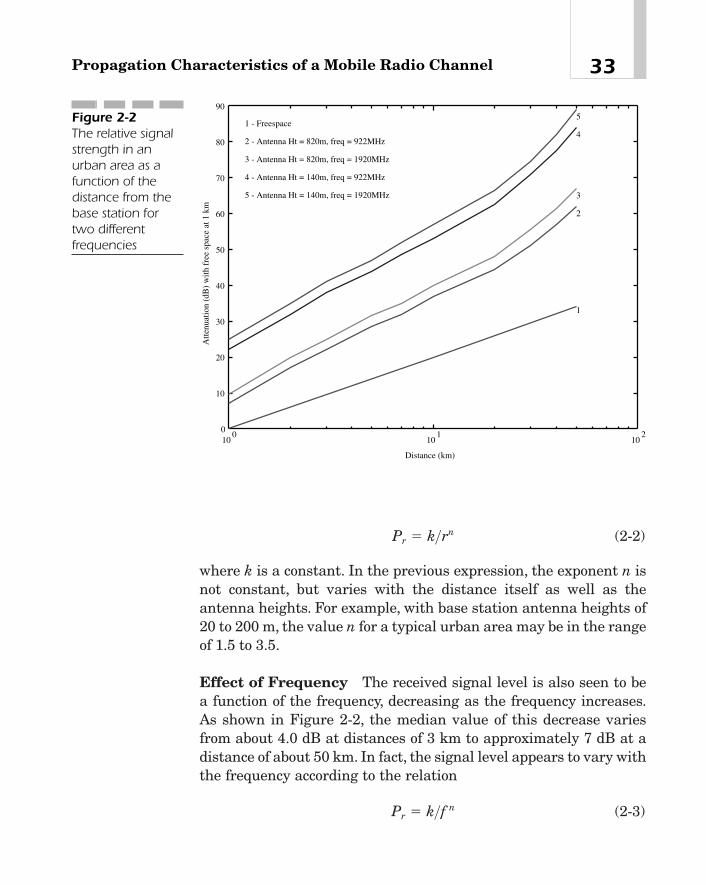
(2-2)
where k is a constant. In the previous expression, the exponent n isnot constant, but varies with the distance itself as well as theantenna heights. For example, with base station antenna heights of20 to 200 m, the value n for a typical urban area may be in the rangeof 1.5 to 3.5.
Effect of Frequency The received signal level is also seen to bea function of the frequency, decreasing as the frequency increases.As shown in Figure 2-2, the median value of this decrease variesfrom about 4.0 dB at distances of 3 km to approximately 7 dB at adistance of about 50 km. In fact, the signal level appears to vary withthe frequency according to the relation
(2-3)Pr � k>f n
Pr � k>rn
33Propagation Characteristics of a Mobile Radio Channel
100
101
102
0
10
20
30
40
50
60
70
80
90
Distance (km)
Atte
nuat
ion
(dB
) w
ith f
ree
spac
e at
1 k
m
1
2
3
4
51 - Freespace
2 - Antenna Ht = 820m, freq = 922MHz
3 - Antenna Ht = 820m, freq = 1920MHz
4 - Antenna Ht = 140m, freq = 922MHz
5 - Antenna Ht = 140m, freq = 1920MHz
Figure 2-2The relative signalstrength in anurban area as afunction of thedistance from thebase station fortwo differentfrequencies

where k is a constant. Table 2-1 lists approximate values of n for dif-ferent distances and frequency bands.
Effect of Antenna Heights The received signal level increaseswith base station antenna heights. See Figure 2-2. This increase inthe signal also depends on the distance between the mobile stationand base station antennas. For distances of up to 10 km, the signallevel increases by about 6 dB/octave. At longer distances, the signalincreases by 9 dB/octave if the base station antenna is higher than200 m or so, but by only 6 dB/octave if the antenna heights are lower.This trend in the signal variation as a function of the base stationantenna height is almost independent of the frequency.
The signal level also depends on the mobile antenna height. Forexample, if the height is increased from 1.5 m to 3 m, the increase inthe signal level is about 3 dB [2]. However, this increase is virtuallyconstant at all distances from the base station.
Effect of Other Parameters Other factors that affect the signalattenuation include irregular terrain such as rolling hills, isolatedmountains, mixed land-sea paths, tunnels, foliage, bodies of water,and so on, and orientation of the street traversed by a vehicle withrespect to a radius from the base station. Although there have beensome experimental studies of these parameters, there is no sufficientdata to make any conclusive statement about their effects. Okumuraet al. suggested some correction factors that can be used to predictthe signal level in rolling, hilly terrain. Generally, the signal leveldecreases as the average terrain undulation height averaged over a
Chapter 234
Value of n in equation Value of n in equation
Distance from (2-3) at 500—1,000 (2-3) at 1,000—2,000
transmitter (km) MHz band MHz band
1—20 0.35—0.42 0.5—0.6
20—100 0.42—0.66 0.6—0.8
Table 2-1
Values ofexponent n inthe expression forthe receivedsignal as afunction of thefrequency
TEAMFLY
Team-Fly®
few kilometers increases. For a more detailed description, the inter-ested reader is referred to [1], [2].
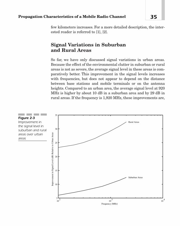
Signal Variations in Suburban and Rural Areas
So far, we have only discussed signal variations in urban areas.Because the effect of the environmental clutter in suburban or ruralareas is not as severe, the average signal level in these areas is com-paratively better. This improvement in the signal levels increaseswith frequencies, but does not appear to depend on the distancebetween base stations and mobile terminals or on the antennaheights. Compared to an urban area, the average signal level at 920MHz is higher by about 10 dB in a suburban area and by 29 dB inrural areas. If the frequency is 1,920 MHz, these improvements are,
35Propagation Characteristics of a Mobile Radio Channel
102
103
104
5
10
15
20
25
30
35
Frequency (MHz)
Impr
ovem
ent i
n S
igna
l Lev
el (
dB)
Rel
ativ
e to
Urb
an A
reas
Suburban Areas
Rural Areas
Figure 2-3Improvement inthe signal level insuburban and ruralareas over urbanareas

respectively, about 12 dB and 32.5 dB. Okumura et. al [2] have sug-gested using some prediction curves to compute this signal improve-ment that is statistically valid for most suburban and rural areas.These curves are shown in Figure 2-3.
Variation of the Local Mean Signal Level
It is evident from the previous discussions that even if such factorsas the distance from the base station, the antenna heights, fre-quency, and so on were to remain the same, the local mean signallevel3, because of the environmental clutter, would vary randomly. Infact, this variation is found to have a log-normal distribution.4 Nogeneral characterization can be made of its standard deviation. Forthe city of New York, it is about 8 dB at a distance of about 2 km fromthe base station and increases to 12 dB at points farther away fromthe transmitter. In other cities, it may either decrease with the dis-tance or may not vary with the distance at all but instead maydepend only upon the frequency.
In general, then, the received signal at a distance r from the trans-mitter may be given by
(2-4)
where k is a constant that depends on the transmitter and receiverantenna heights. The exponent n depends on the environment. Val-ues of n for a few environments are given in Table 2-2.
Pr1r 2 �kAtAr
rn Pt
Chapter 236
3When we talk about the local mean signal, it is understood that variations of thereceived signal due to fading have been removed by averaging the received signal overa distance of about 10 to 20 m.4The density function of a log-normal variable is given by the following expression:
where m is the average value of the variable x and s2 is the variance. In other words,the mean signal level when expressed in decibels, has a normal distribution.
f1x 2 �
1
x22ps2 e� 1lnx �m22
2s2 4 , if x 7 0
0 otherwiseu

If Pt is in watts, then taking the logarithm of expression (4), thereceived power Pr in dB is given by
If Pt is in dB, and Gt and Gr are respectively the transmitter andreceiver antenna gains in dB, then the previous expression may berewritten as
where a is a constant. The received signal power Pr (in dB) may alsobe expressed in terms of the signal Pr0
(in dB) at a reference distance,say, r0:
The reference distance r0 may be taken as 1 km for cells of anaverage size.5 In this case,
(2-5)
Notice that if n is assumed to be 4, the average signal at a distanceof 10 km is 40 dB below the signal at 1 km.6 Like the exponent n, sig-
Pr � Pr0� 10n log1r 2
Pr � Pr0� 10n log1r>r0 2
Pr1dB 2 � a � Pt 1dB 2 � Gt � Gr � 10n log1r 2
Pr � 10 log1k 2 � 10 log Pt � 10 log At � 10 log Ar � 10n log1r 2
37Propagation Characteristics of a Mobile Radio Channel
Transmission Environment Values of n in equation (2-4)
Outdoor urban and dense urban areas 3.0—4.0
Indoor urban and dense urban areas 4.5—6.0
Rural areas 2.0—3.0
Table 2-2
Values ofexponent n that determineRF signalattenuation in differentenvironments
5For microcells, it is about 100 m or less. For picocells, it could be a few meters.6For this value of n, if the distance increases by a factor of 10, the signal decreases by40 dB. In other words, the signal falls at a rate of 40 dB per decade.

nal level Pr0at a reference distance r0 also depends upon the envi-
ronment. For rural areas, this value is higher than for an urban envi-ronment. As an example, assume that 1w (that is, 30 dBm) istransmitted from a base station antenna. Then typical signal varia-tions as a function of the distance are shown in Figure 2-4.
The actual signal level measured at any point differs from the cal-culated value using equation 2-1(f). This difference, referred to in theliterature as an excess path loss, is also a log-normal distribution.Actual measurements in New York and New Jersey show that forurban areas, the excess path loss has a standard deviation of about8 to 12 dB for locations about 1 mile from the base station. As we will
Chapter 238
r (km)TransmitAntenna
ro
1 10.0 100
Pr (dBm)
-60.0
-70.0
-80.0
-90.0
-100.0
-110.0
-120.0
-130.0
-140.0
Urban Suburban
Rural
Figure 2-4An example ofvariations of thereceived signalwith distance forurban, suburban,and rural areas
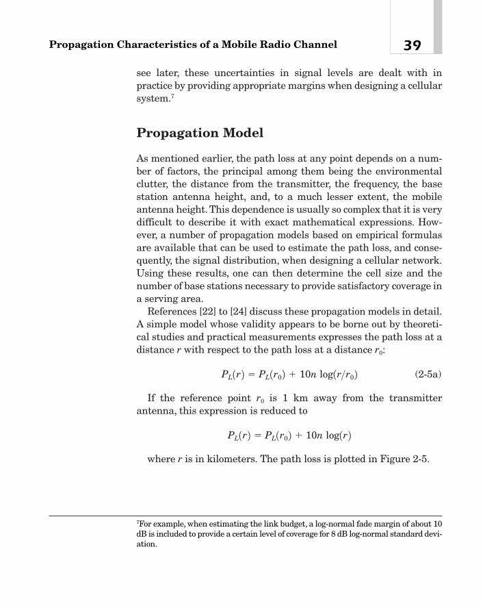
see later, these uncertainties in signal levels are dealt with inpractice by providing appropriate margins when designing a cellularsystem.7
Propagation Model
As mentioned earlier, the path loss at any point depends on a num-ber of factors, the principal among them being the environmentalclutter, the distance from the transmitter, the frequency, the basestation antenna height, and, to a much lesser extent, the mobileantenna height.This dependence is usually so complex that it is verydifficult to describe it with exact mathematical expressions. How-ever, a number of propagation models based on empirical formulasare available that can be used to estimate the path loss, and conse-quently, the signal distribution, when designing a cellular network.Using these results, one can then determine the cell size and thenumber of base stations necessary to provide satisfactory coverage ina serving area.
References [22] to [24] discuss these propagation models in detail.A simple model whose validity appears to be borne out by theoreti-cal studies and practical measurements expresses the path loss at adistance r with respect to the path loss at a distance r0:
(2-5a)
If the reference point r0 is 1 km away from the transmitterantenna, this expression is reduced to
where r is in kilometers. The path loss is plotted in Figure 2-5.
PL1r 2 � PL1r0 2 � 10n log1r 2
PL1r 2 � PL1r0 2 � 10n log1r>r0 2
39Propagation Characteristics of a Mobile Radio Channel
7For example, when estimating the link budget, a log-normal fade margin of about 10dB is included to provide a certain level of coverage for 8 dB log-normal standard devi-ation.
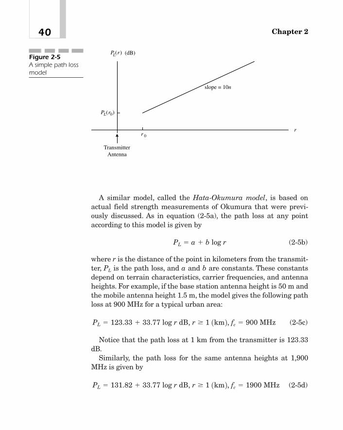
A similar model, called the Hata-Okumura model, is based onactual field strength measurements of Okumura that were previ-ously discussed. As in equation (2-5a), the path loss at any pointaccording to this model is given by
(2-5b)
where r is the distance of the point in kilometers from the transmit-ter, PL is the path loss, and a and b are constants. These constantsdepend on terrain characteristics, carrier frequencies, and antennaheights. For example, if the base station antenna height is 50 m andthe mobile antenna height 1.5 m, the model gives the following pathloss at 900 MHz for a typical urban area:
(2-5c)
Notice that the path loss at 1 km from the transmitter is 123.33dB.
Similarly, the path loss for the same antenna heights at 1,900MHz is given by
(2-5d)PL � 131.82 � 33.77 log r dB, r � 1 1km 2, fc � 1900 MHz
PL � 123.33 � 33.77 log r dB, r � 1 1km 2, fc � 900 MHz
PL � a � b log r
Chapter 240
slope = 10n
P rL( )
r
P rL( )0
(dB)
r 0
TransmitterAntenna
Figure 2-5A simple path lossmodel

The path loss in suburban and open areas is less than in urbanareas. For example, at 1,950 MHz, this improvement in path loss isabout 12 dB for suburban and 32 dB for open areas.
Short-term Variations of the SignalAs described before, in urban and dense urban areas, there is veryoften no direct line-of-sight path between a mobile and a base sta-tion. In these instances, the signal is composed of a large number ofreflected rays because of scattering and reflections from buildingsand obstructions. As a result, over short distances, say, of the order ofa few wavelengths, the average signal level received at any pointremains virtually constant, but its instantaneous value (that is, theenvelope of the RF signal) varies randomly about the mean levelwith a Rayleigh distribution, while its phase is uniformly distributedbetween 0 and 2p. Because in those cases that are of interest to us,the received signal e at a mobile antenna may consist of a number ofrandomly varying components; we can represent it as
(2-6)
where x1 and x2 are two independent Gaussian random variableswith zero mean and equal variance, say, E2
rms, and vc is the carrierfrequency [21]. The amplitude of e is given by the random variable
. The variable z, defined this way, may be shown tohave Rayleigh distribution [25] with the probability density functiongiven by
(2-7)
Figure 2-6 shows the amplitude variations of a Rayleigh fadingsignal. As the mobile moves through this signal pattern, the ampli-tude of the received signal varies, going alternately through themaxima and minima. When the amplitude falls below a given levelwith respect to its average value, we say that the mobile has goneinto a fade.
f1z 2 �2z
Erms2 e� z2
E2rms, z � 0
z � 2x21 � x2
2
e � x1 cosvct � x2 sinvct
41Propagation Characteristics of a Mobile Radio Channel

The rate, NR, at which the instantaneous value of the received sig-nal goes below the level z � E is called the level crossing rate and isgiven by [21]
(2-8)
where fd � n/l is the Doppler shift due to a mobile velocity n and car-rier wavelength l.8
The average duration of a fade at level z � E is given by [21]:
(2-9)
Obviously, the level crossing rate, which is the same as the num-ber of fades per second, and the fade duration depends on the fadelevel, among many other parameters. Table 2-3 shows the number offades per second at 850 MHz. The average fade duration for thesame carrier is given in Table 2-4. Notice that the deeper the fade
w �122p fd
Erms
E 1e1E>Erms22 � 1 2
NR � 22p fd EErms
e� 1E>Erms22
Chapter 242
Received Signal Envelope
Distance from Transmitter
Average Signal Level
Fade Level = - R dB
Fade
Fade Width
/ 2λ
Figure 2-6A Rayleigh fadingsignal. The figureshows fades at asignal level R withrespect to theaverage signal. The signal minimaoccur approx-imately at one-halfthe wavelength.
8The fade level is usually specified in dB. For example, there may be a �10 dB fade.In this case, 20log(E/Erms) � �10, or E/Erms � 0.316228.

level (that is, the larger the absolute value of R in Figure 2-6) withrespect to the average value of the signal, the fewer the number offades per second and the shorter the fade duration.
Assuming that an unmodulated carrier at frequency vc is trans-mitted, if a mobile moves with a constant velocity v, the power spec-trum of the received carrier is no longer confined to vc , but isdistributed over a frequency band 0v � vc0 � vd, where, as before,
(2-10)
is the Doppler shift in radians.9 Here, a is the angle between thedirection of the incident signal and the direction of the vehiclemotion as shown in Figure 2-7. The power spectral density S(v) ofthe received signal envelope is given by
(2-11)S1v 2 �E2
rms
vd c1 � a v � vc
vdb2 d �0.5
vd �2pVl
cos a
43Propagation Characteristics of a Mobile Radio Channel
Vehicle Speed (km/h) �10 dB fades �15 dB fades
32 18 10.8
112 64 38.4
Table 2-3
The number offades/second at850 MHz
Vehicle Speed (km/h) �10 dB fade �15 dB fade
32 5.31 2.88
112 1.49 0.81
Table 2-4
The average fadeduration (in ms)at 850 MHz
9In other words,vd is the maximum apparent change in the frequency of the receivedsignal due to the Doppler effect.

for 0v� vc0� vd and is depicted in Figure 2-8. Figure 2-8(a) shows thespectrum of an unmodulated carrier transmitted by a base station.Here, all the energy is concentrated in a single frequency vc. Whenthis signal is received by a mobile station that is travelling at a veloc-ity n, the energy is no longer concentrated in the carrier frequencyalone but instead distributed over a bandwidth 2vd around vc as inFigure 2-8(b).10
The above analysis assumes that the antenna used is omnidirec-tional, and that the signal is arriving at the mobile antenna at all
Chapter 244
V
MultipathSignal
Figure 2-7The direction of theincoming signalwith respect to thevehicle velocity
10In practical terms, this means that when an unmodulated carrier is being trans-mitted, the output at the baseband of a stationary receiver is a low-level thermalnoise, which, for an average carrier-to-noise ratio, would be inaudible. If the receivernow moves at a velocity n, the output at the baseband will be an audible noise withnoise power concentrated in a narrow band of frequencies that depends on the veloc-ity and the carrier frequency.
ωc ω ωc d+ω ωc d−
( / ) ( )ω ωd rmsE S2
ωc
f f
(a) (b)
Pow
er S
pect
ral D
ensi
ty
Figure 2-8Effect of mobilityon an RF signal. (a) The powerspectrum of anunmodulatedcarrier transmittedby a base station.(b) The powerspectrum of thesignal envelopereceived at theantenna of amoving vehicle.
TEAMFLY
Team-Fly®

angles with equal probability. As indicated before, Erms is the RMSvalue of the signal envelope. Equations 2-6 and 2-7 show that ran-dom fluctuations of the received signal envelope depend on the vehi-cle velocity and the carrier frequency and may in some cases be 30dB or more below the average value of the signal.
In suburban areas, the signal may, sometimes have a direct pathand a few indirect paths as well, although possibly not as many as inan urban area. In rural areas, there is often a direct path, anddepending on the terrain, the signal may also come over one or tworeflected paths. When there is a direct line-of-sight component inaddition to one or more reflected rays, the channel is said to be aRician fading channel.11
Effect of Short-term Variations
In a digital system, short-term variations of the RF signal result inburst errors in the received data stream. When the signal goes intoa fade, the data bits in the faded portion of the signal are in errorwith a probability that usually depends upon the fade level. Tounderstand the severity of the burst errors, consider a narrow-bandsystem (such as TDMA based on IS-136 or GSM). Assume that thecarrier frequency is 850 MHz and that the mobile velocity is 32km/h. In this case, the signal falls 15 dB below its local mean about11 times a second, and each time remains below that level about 3ms (see Tables 2-3 and 2-4). Hence, the signal is in a fade approxi-mately three percent of the time.12 Thus, for a �15 dB fade, assum-ing that the probability of a faded bit being in error is 0.5, the bursterrors during a fade will result in a bit error rate of 0.015. Becausewideband CDMA systems are inherently less susceptible to fades,the burst error rates due to the vehicle motion are less severe in
45Propagation Characteristics of a Mobile Radio Channel
11The signal with Rician distribution is given by
where x0 is a constant line-of-sight component, and x1 and x2 are two independentGaussian random processes as in equation 2-6.12That is, during each second, the signal is in a fade 3�11 � 33 ms.
e � Re 3 1x0 � x1 � jx2 2e�jvct 4

these systems.13 Also, because a mobile radio channel is time varying,and because the signal at a mobile antenna is subjected to a Dopplershift that varies with the mobile velocity, the signal frequency as per-ceived at a mobile station goes through a random variation with time.This phenomenon, which is known as random FM, manifests itself asadditional noise in the baseband, which in a digital system may causethe bit error rate to increase even more.
Coherence Bandwidth and Power Delay ProfilesTo understand coherence bandwidth, assume for simplicity that sig-nals are being transmitted at two different frequencies over a mobileradio channel. If the difference between the two frequencies is small,the two signals fade in the same way. In other words, their short-term variations (with respect to time) have identical statistical prop-erties and consequently are correlated to each other. As theseparation between the frequencies is increased, they begin to fadedifferently, and if the separation is wide enough, the signal varia-tions become statistically independent. The separation between thetwo frequencies that the signal variations are correlated below iscalled the coherence bandwidth. When the channel bandwidth is lessthan the coherence bandwidth, the resulting fading is called flat fad-ing. If the channel bandwidth is any greater, it leads to a frequency-selective fading.
Suppose that a base station transmits a single pulse on a coherentchannel as shown in Figure 2-9. As we have seen earlier, this resultsin a number of reflected rays, each of which travels to a mobile sta-tion along a different path. Because of attenuation, only a finitenumber of rays have sufficient energy to be useful at a mobile sta-tion. In Figure 2-9(b), only three reflected waves are shown to haveany significant amount of energy, the last two being delayed withrespect to the first by, respectively, t1 and t2. The variation of the sig-
Chapter 246
13See Chapter 3 “Principles of Wideband CDMA.”
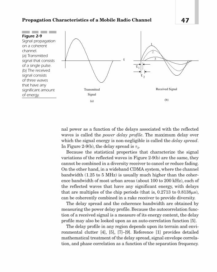
nal power as a function of the delays associated with the reflectedwaves is called the power delay profile. The maximum delay overwhich the signal energy is non-negligible is called the delay spread.In Figure 2-9(b), the delay spread is t2.
Because the statistical properties that characterize the signalvariations of the reflected waves in Figure 2-9(b) are the same, theycannot be combined in a diversity receiver to cancel or reduce fading.On the other hand, in a wideband CDMA system, where the channelbandwidth (1.25 to 5 MHz) is usually much higher than the coher-ence bandwidth of most urban areas (about 100 to 200 kHz), each ofthe reflected waves that have any significant energy, with delaysthat are multiples of the chip periods (that is, 0.2713 to 0.8138ms),can be coherently combined in a rake receiver to provide diversity.
The delay spread and the coherence bandwidth are obtained bymeasuring the power delay profile. Because the autocorrelation func-tion of a received signal is a measure of its energy content, the delayprofile may also be looked upon as an auto-correlation function [5].
The delay profile in any region depends upon its terrain and envi-ronmental clutter [4], [5], [7]—[9]. Reference [1] provides detailedmathematical treatment of the delay spread, signal envelope correla-tion, and phase correlation as a function of the separation frequency.
47Propagation Characteristics of a Mobile Radio Channel
1
2
Transmitted
Signal
Received Signal
1
2
3t
(a) (b)
τ
τ
Figure 2-9Signal propagationon a coherentchannel. (a) Transmittedsignal that consistsof a single pulse.(b) The receivedsignal consists of three waves that have anysignificant amountof energy.

Cox and Leck [4], [5] have studied the delay spreads, excess delays,14
and distributions of delay spreads in selected areas of New York Cityand have found that at 910 MHz, the maximum delay spread is about3.5 ms. The delay spread exceeds 3 ms in 5 percent of the areas wheremeasurements were taken, 2.5 ms in about 10 percent of the areas,and 1.2 ms in 50 percent of the region. Determination of the cumula-tive distribution from these values indicates that the delay spreadapproximates a log-normal distribution with a mean of 1.3 ms and astandard deviation of 0.6 ms. The excess delay, on the other hand, isfound to have a mean of 1.1 ms, standard deviation of 0.9 ms, and amaximum value of about 4 ms, and exceeds 2 ms in about 10 percentof the areas observed. Evidently, the delay spread is smaller in sub-urban and rural areas and possibly the smallest in those areas thathave a direct line-of-sight path as in a satellite communications sys-tem [17].Table 2-5 gives average delay spreads for typical urban, sub-urban, rural, and in-building communications channels.
Reference [5] gives measured power delay profiles of a few placesin New York City. These profiles are generally not smooth functionsof the delay variations. However, to further explain our ideas, somesimple, idealized power delay profiles are shown in Figure 2-10. InFigure 2-10(a), the maximum delay that might be considered in thedesign of a rake receiver is 4 ms. However, most of the signal energyis concentrated in multipaths that have delays of 2.0 ms or less.
Chapter 248
Environment Class Average Delay Spread (ms)
Urban area 2.5
Suburban area 0.5—1.5
Rural/open area 0.1—0.25
In-building 0.1
Table 2-5
Delay spreads fortypical urban,suburban, rural,and in-buildingchannels
14The excess delay is the average delay spread (obtained by taking the first momentof the power delay profile) less the first arrival delay.

A number of empirical formulas based upon field measurementshave been used to express the coherence bandwidth [5], [23]. As anexample, the following expression defines this bandwidth Bcoherence interms of the average delay:
where tav is the average value of the delay spread. If Figure 2-10 (b)is the power delay profile of a certain urban area, then because tav �
1.5 ms, the coherence bandwidth is
Simulation Model of a Mobile Radio ChannelIn many instances, it is useful to simulate multipath signals in thelaboratory because in the absence of such simulation, one wouldhave to actually build the system, test it in the field to see if it actu-ally works satisfactorily in a mobile environment, adjust the designparameters if necessary, retest, and repeat the process until thedesired performance is achieved.
Bcoherence � 0.16>tav � 106.67 kHz
Bcoherence � 0.16>tav
49Propagation Characteristics of a Mobile Radio Channel
t ( )
Rel
ativ
e Si
gnal
Ene
rgy
(dB
)
1 4
-20
0
s-40
2 4 6 8( ) st
0
-20
-40
(a) (b)
Excess Delay
Rel
ativ
e Si
gnal
Ene
rgy
(dB
)
av
2 3Excess Delay
µ µ
τ
Figure 2-10Two idealizedpower delayprofiles showingthe signal energyas a function of thedelay relative to adirect ray

A number of procedures for simulating a mobile radio channelhave been suggested by various authors [11]—[17]. The procedurepresented here is based on the fact that the power delay profile of amobile radio environment may be resolved into a small number ofmultipaths that have significant energy [3].
A block diagram of the simulation model is shown in Figure 2-11.The signal on each path i is attenuated by e��i (where ai is the atten-uation in dB) and delayed by ti second. The first branch represents adirect line-of-sight path between the transmitter and receiver anten-nas. The delayed signal from each of the other paths is passedthrough a Doppler shaping filter. The frequency response of this fil-ter, which is shown in Figure 2-12, is designed to approximate thetheoretical spectrum of the received signal envelope of Figure 2-8(b)[11]. Notice that the filter response increases to a peak value at theDoppler frequency vd/2p [11] and then falls off at 18 dB/octave. Sig-nals from all branches are summed together and then combinedwith additive white Gaussian noise. The resulting output simulatesthe signal received over a mobile radio channel. The number ofpaths, the attenuation, and delay of each are obtained from thepower delay profile.
Reference [3] discusses five mobile radio channels corresponding tothe following environments: urban fast, urban slow, rural, terrain-obstructed, and satellite mobile channels. In most urban areas, thereis no direct path, and as such their simulation excludes the first
Chapter 250
X X
+X
X
Delay = 1
Delay = 2
Delay = n
ooo
DopplerShaping
Filter
DopplerShaping
Filter
ModulatedSignal
Additive WhiteGaussian Noise
Output Signal
e−α1
e−α2
e n−α
e j td− ω
Σ
τ
τ
τ
Figure 2-11A simulation modelof the Rayleighfading channel.The Dopplershaping filter has a Doppler spreadof vd/2p Hz wherevd � 2pV/l. HereV is the vehiclespeed, and l iswavelength of thecarrier frequency.

branch of Figure 2-11.The number of paths to be included depends onthe environment.15 For example, nine paths, as shown in Table 2-6,have been used in simulating a mobile radio channel in a typicalurban area for Digital Audio Radio (DAR) systems. For the represen-tative power delay profiles of other environments, see Reference [3].
51Propagation Characteristics of a Mobile Radio Channel
18 dB/octave
6 dB
S ( )
d
ω
ω
Figure 2-12The frequencyresponse of theDoppler shapingfilter
15A satellite channel usually consists of a line-of-sight ray, but may include one or twomultipaths as well.
Path # Attenuation (dB) Delay (�s)
1 2 0
2 0 0.25
3 3 0.5
4 4 0.75
5 2 1.0
6 0 1.25
7 3 2.0
8 5 2.5
9 10 3.0
Table 2-6
The power delayprofile for anurban area usedin testing DARsystems

SummaryIn this chapter, we have described the propagation characteristics ofa mobile radio channel. There are two types of variations experi-enced by an RF signal—the large scale variations observed over rel-atively long distances, say, a few tens or hundreds of wavelengths ofthe carrier, and short-term variations that result from multipathreflections and occur over very short distances, such as a fraction ofthe wavelength. Factors responsible for large-scale variationsinclude clutter and environmental obstructions, distance from thetransmitter, the carrier frequency, antenna heights, and so on. Signalvariations as functions of these parameters are described in terms offield measurements and empirical relations. The mean signal levelat any point obtained by averaging it over a small area around thatpoint varies randomly with a log-normal distribution. Simple modelsare presented that can be used to compute the path loss of a mobileradio channel. Short-term variations have a Rayleigh distributionand may cause the instantaneous value of the signal envelope tovary by as much as 30 to 40 dB about the local mean. The effect ofthese variations, the coherence bandwidth, and power delay profilesare discussed. We conclude the chapter with a simulation model of amobile radio channel. The model consists of a small number ofresolvable paths, each associated with an attenuation and delay thatcharacterize the particular propagation environment—urban, sub-urban, or rural—that is being simulated.
References[1] W.C. Jakes, Jr. (Ed.), Microwave Mobile Communications.
New York: John Wiley, 1974.
[2] Y. Okumura, et al., “Field Strength and Its Variability in VHFand UHF Land-Mobile Radio Service,” Review of the Electri-cal Communication Laboratory, Vol. 16, No. 9—10, Septem-ber—October, 1968, pp. 825—873.
[3] L.Thibault, G. Soulodre, and T. Grusec, “EIA/NRSC DAR Sys-tems Subjective Tests Part II: Transmission Impairments,”
Chapter 252

IEEE Trans. Broadcasting, Vol. 43, No. 4, December 1997, pp.353—369.
[4] D.C. Cox and R.P. Leck, “Distributions of Multipath DelaySpread and Average Excess Delay for 910-MHz UrbanMobile Radio Paths,” IEEE Trans. Ant. & Prop., Vol. AP-23,No. 2, March 1975, pp. 206—213.
[5] D.C. Cox and R.P. Leck, “Correlation Bandwidth and DelaySpread Multipath Propagation Statistics for 910-MHz UrbanMobile Radio Paths,” IEEE Trans. Comm, Vol. COM-23, No.11, November 1975, pp. 1271—1280.
[6] R.D.J. van Nee, et al., “Rician Fading Land-Mobile SatelliteChannel,” IEEE J. Sel. Areas Comm., Vol. 10, No. 2, February1992, pp. 350—357.
[7] A. Afrashteh, et al., “Performance of a TDM/TDMA PortableRadio Link for Interference, Noise, and Delay Spread Impair-ments,” IEEE Trans. Veh. Tech., Vol. 43, No. 1, February 1994,pp. 1—7.
[8] M.J. Feuerstein, et al., “Path Loss, Delay Spread, and OutageModels as Functions of Antenna Height for MicrocellularSystem Design,” IEEE Trans.Veh.Tech.,Vol. 43, No. 3,August1994, pp. 487—497.
[9] E.S. Sousa, et al., “Delay Spread Measurements for the Digi-tal Cellular Channel in Toronto,” IEEE Trans. Veh. Tech., Vol.43, No. 4, November 1994, pp. 837—847.
[10] N.L.B. Chan, “Multipath Propagation Effects on a CDMACellular System,” IEEE Trans. Veh. Tech., Vol. 43, No. 4,November 1994, pp. 848—855.
[11] G.A. Arredondo, et al., “A Multipath Fading Simulator forMobile Radio,” IEEE Trans. Comm., Vol. COM-21, No. 11,November 1973, pp. 1325—1328.
[12] J.I. Smith, “A Computer Generated Multipath Fading Simu-lation for Mobile Radio,” IEEE Trans. Veh. Tech., Vol. VT-24,No. 3, August 1975, pp. 39—40.
[13] M.R. Karim, “Packet Communications on a Mobile RadioChannel,” AT&T Tech. J., Vol. 65, Issue 3, May/June 1986, pp.12—20.
53Propagation Characteristics of a Mobile Radio Channel

[14] C. Loo, et al., “Computer Models for Fading Channels withApplications to Digital Transmission,” IEEE Trans. Veh.Tech., Vol. 40, No. 4, November 1991, pp. 700—707.
[15] C. Loo, “A Statistical Model for a Land Mobile Satellite Link,”IEEE Trans. Veh. Tech., Vol. VT-34, No. 3, August 1985, pp.122—127.
[16] G.E. Corazza, et al., “A Statistical Model for Land MobileSatellite Channels and Its Applications to NongeostationaryOrbit Systems,” IEEE Trans. Veh. Tech., Vol. 43, No. 3, August1994, pp. 738—741.
[17] E. Lutz, et al., “The Land Mobile Satellite CommunicationChannel—Recording, Statistics, and Channel Model,” IEEETrans. Veh. Tech., Vol. 40, No. 2, May 1991, pp. 375—385.
[18] W.R. Young, Jr., “Comparison of Mobile Radio Transmissionat 150, 450, 900, and 3700 MC,” Bell System Tech. J. 31,November 1952, pg. 1068.
[19] D.M. Black and D.O. Reudink, “Some Characteristics of RadioPropagation at 800 MHz in the Philadelphia Area,” IEEETrans. Veh. Tech., Vol. 21, May 1972, pp. 45—51.
[20] D.O. Reudink, “Comparison of Radio Transmission at X-BandFrequencies in Suburban and Urban Areas,” IEEE Trans.Ant. Prop., AP-20, July 1972, pg. 470.
[21] W.C. Jakes, Jr., “A Comparison of Specific Space DiversityTechniques for Reduction of Fast Fading in UHF MobileRadio Systems,” IEEE Trans. Veh. Tech., Vol. VT-20, No. 4,November 1971, pp. 81—92.
[22] M. Hata, “Empirical Formula for Propagation Loss in LandMobile Radio Services,” IEEE Trans. Veh. Tech., Vol. 29, May1980.
[23] K. Garg, IS-95 and cdma2000. New Jersey: Prentice Hall,2000, pp. 232—243.
[24] J. Lee and L. Miller, CDMA Systems Engineering Handbook.Artech House, 1998.
[25] A. Papoulis, Probability, Random Variables and StochasticProcesses. New York: McGraw-Hill, 1965.
Chapter 254
TEAMFLY
Team-Fly®
Principles ofWideband
CDMA (W-CDMA)
CHAPTER 33
Copyright 2002 M.R. Karim and Lucent Technologies. Click Here for Terms of Use.

IMT-2000 has defined four 3G systems, only one of which, namely,UWC-136 is based upon the time division multiple access (TDMA)scheme, while the other three—Universal Mobile Telecommunica-tions System (UMTS) W-CDMA Frequency Division Duplex (FDD),UMTS W-CDMA Time Division Duplex (TDD), and cdma2000—usedirect-sequence code division multiple access (DS-CDMA).1 In fact,CDMA appears to be the preferred technology for wireless commu-nications because of the many advantages it offers including, forexample, the multipath diversity and soft handoff [1], [31]. The pur-pose of this chapter is to provide the reader with a basic under-standing of the principles of wideband CDMA technology. Thechapter begins with an overview of the various access technologies.It next considers a wideband CDMA system architecture and pre-sents some technical detail of its various physical layer components.
Multiple Access SchemesUMTS W-CDMA FDD is a direct-sequence CDMA system with anominal bandwidth of 5 MHz [16], [19], [20]. The second system,UMTS W-CDMA TDD, also uses CDMA with a bandwidth of 5 MHz,but now the frequency band is time shared in both directions—onehalf of the time, it is used for transmission in the forward directionand the other half of the time in the reverse direction. cdma2000 isa multicarrier, direct-sequence CDMA FDD system. Like cdmaOne,its first phase is expected to use a single carrier with a bandwidth of1.25 MHz. In the second phase, it may have as many as three carri-ers. In this system, even though each carrier has a nominal band-width of 1.25 MHz, the total bandwidth required is 5 MHz. Thefourth system supported by IMT-2000 is based upon a TDMAscheme whereby each physical channel is divided into a number offixed, synchronized time slots. Each user is assigned one or moreslots and is permitted to transmit its information only during its
Chapter 356
1To be more accurate, however, W-CDMA UMTS TDD uses a combination of TDMAand CDMA schemes.
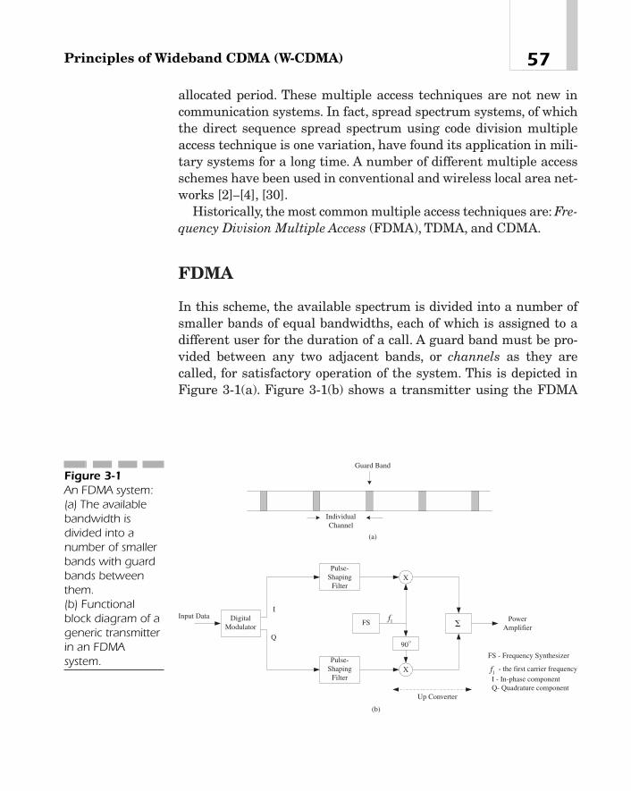
allocated period. These multiple access techniques are not new incommunication systems. In fact, spread spectrum systems, of whichthe direct sequence spread spectrum using code division multipleaccess technique is one variation, have found its application in mili-tary systems for a long time. A number of different multiple accessschemes have been used in conventional and wireless local area net-works [2]—[4], [30].
Historically, the most common multiple access techniques are: Fre-quency Division Multiple Access (FDMA), TDMA, and CDMA.
FDMA
In this scheme, the available spectrum is divided into a number ofsmaller bands of equal bandwidths, each of which is assigned to adifferent user for the duration of a call. A guard band must be pro-vided between any two adjacent bands, or channels as they arecalled, for satisfactory operation of the system. This is depicted inFigure 3-1(a). Figure 3-1(b) shows a transmitter using the FDMA
57Principles of Wideband CDMA (W-CDMA)
Input DataFS
DigitalModulator
X
X
900
I
Q
PowerAmplifier
f1
FS - Frequency Synthesizer
- the first carrier frequencyf1
Pulse-Shaping
Filter
I - In-phase componentQ- Quadrature component
Up Converter
Pulse-Shaping
Filter
Guard Band
IndividualChannel
(a)
(b)
�
Figure 3-1An FDMA system:(a) The availablebandwidth isdivided into anumber of smallerbands with guardbands betweenthem. (b) Functionalblock diagram of ageneric transmitterin an FDMAsystem.

technique. An FDMA system would actually consist of many of thesetransmitters, each using a different carrier frequency. Pulse-shapingfiltering of the incoming data is usually done at the base band. Anexample of this access mechanism is cellular system TIA-553, whereeach channel has a bandwidth of 30 kHz. Separate channels areused on uplinks and downlinks.
TDMA
In TDMA [5], information from multiple users is sent out in fixed-size frames, each consisting of a number of equal time slots. Anygiven user may be assigned one or more of these slots and is allowedto transmit only during the allocated slot(s) in each frame using theentire bandwidth of the channel.2 A guard period must be providedbetween any two adjacent time slots so that transmissions from different users do not overlap. The access scheme is illustrated inFigure 3-2.
Digital systems, such as the North American standard IS-54, itsnewer version IS-136, and Global System for Mobile Communica-tions (GSM), are all based on TDMA and FDD. In IS-54 and IS-136,each voice channel has a bandwidth of 30 kHz and consists of sixtime slots. For full-rate speech, three users use these six slots in acertain way. For example, user 1 uses time slots 1 and 4, user 2 timeslots 2 and 5, and user 3 time slots 3 and 6. For half-rate speech, oneuser is assigned to each of the six time slots. Because the same band-width is now being time shared among three and possibly six users,the system capacity increases three to six times.
In GSM, on the other hand, each physical channel has a band-width of 200 kHz. Each frame consists of eight time slots. As such,the system can support up to eight users per channel with full-ratespeech. Each TDMA frame is 4.615 ms. Each slot is 0.577 ms, ofwhich the guard period is 0.03462 ms. In these TDMA systems, phys-ical channels use different frequencies as in FDMA.Thus, in essence,they combine TDMA and FDMA schemes.
Chapter 358
2This bandwidth is not to be confused with the available spectrum, which is dividedinto a number of separate channels for use in the TDMA system.

Spread Spectrum Multiple Access
As we have just seen, each user in FDMA or TDMA is allocated afraction of the available bandwidth. In the spread spectrum multipleaccess scheme, on the other hand, all users can transmit simultane-ously on the entire available bandwidth using a pseudorandom codethat is unique for each user. These codes, which are also known aspseudonoise (PN) codes, are random sequences generated by meansof a multistage shift register, where some selected outputs are addedmodulo 2 and fed back to the input of the shift register. As will beshown later in this chapter, the code sequences repeat themselvesafter a finite, although usually quite long, period and behave as ran-dom functions for all practical purposes. The receiver separates thedifferent users by correlating the received signal with these codes.
Many spread spectrum techniques are currently available. Forexample, there are direct sequence spread spectrum (DSSS), fre-quency-hopping spread spectrum (FHSS), time-hopping spread spec-trum (THSS), and hybrid techniques, which are combinations of the
59Principles of Wideband CDMA (W-CDMA)
Input Data DigitalModulation
Q
0Synchronized
Time Base
User 1
User 2
User N
oo
Slot 1 Slot 2 Slot No o otime
Frame
I
Guard Period
(a)
(b)
MUXUp-Converter
andPower Amplifier
TransmitAntenna
Figure 3-2A TDMA system: (a) A TDMA frame(b) A TDMAtransmitter

first three. Because UMTS W-CDMA and cdma2000 use directsequence spread spectrum, only this access scheme will be explainedin this section.
In a direct-sequence spread spectrum system [6], [7], also knownas the CDMA, each user is assigned a unique PN code. Its datastream is first spread out by that PN code, and then modulates thecarrier frequency. The clock rate of the spreading code is known asthe chip rate. This principle is illustrated in Figure 3-3.
The chip rate of the PN code is usually much higher than the userdata rate. The ratio of the chip rate to the data rate is called thespreading factor. In UMTS, the spreading factor varies from 4 to 256.
CDMA Technology
Direct-Spread CDMA Principles
As will be seen later, PN codes have some unique properties. One ofthem is that any physical channel or user application, when spreadby a PN code at the transmitter, can be uniquely identified at thereceiver by multiplying the received baseband signal with a phase-coherent copy of that PN code. To illustrate how a CDMA receivercan detect the signal from a desired user in the presence of signalsreceived from other users in a CDMA system, consider Figure 3-4 (a),which shows the block diagram of an overly simplified CDMAreceiver. Suppose that the receiver wants to detect the data stream
Chapter 360
DigitalModulator
User DataX X Output
CodeGenerator
cf
User's PNCode
Figure 3-3Principles of a DSSS

61Principles of Wideband CDMA (W-CDMA)
Demodulator X Integrator)(trx
)(1 tC
)(1 ts)(tr )(1 tr
Decoder
(a)
Figure 3-4A CDMA system: (a) A simplifiedCDMA receiver. Thereceived signal atthe input of thedemodulator iscomposed ofsignals frommultiple users. The data streamfrom user 1 isbeing detected in this figure. (b) Diagramsshowing how thesignal arriving at areceiver iscomposed of thetransmitted signalsfrom multipleusers. (c) Diagramsillustrating how thesignal from adesired user can bedetected. Thedecoder reads theintegrator outputat the end of eachsymbol period, andif it is positive, ittakes the data tobe a binary zero. Ifit is negative, thedata is decoded tobe a binary one.Notice that afterthe decoder hasread the integratoroutput, theintegrator must(cont.)
cT
bT
10 0
User 1 Data
User 1 PN Code
)(1 tC
)(1 ts
)(*)( 11 tCts
)(2 ts
)(2 tC
)(*)( 22 tCts
)(3 ts
)(3 tC
)(*)( 33 tCts
t
t1
0
DemodulatorOutput =
s t C ti ii
( ) ( ) =�
1
3
(b)

from user 1. The received signal from multiple users is first demod-ulated. The output of the demodulator, which is a baseband signal, ismultiplied by the PN code assigned to user 1. The resulting output isapplied to the input of an integrator where it is integrated over eachsymbol period. The decoder reads the output of the integrator and
Chapter 362
Figure 3-4 cont.be reset (that is, itsoutput must bedumped) so thatthe process canrecommence at thestart of the nextsymbol period.
10User 1
Decoded Data
User 1 PN Code
)(1 tC t
1
DemodulatorOutput 1
2
3
-3
-2
-1
DemodulatorOutput * User 1
Code
IntegratorOutput
2
4
6
12
-2
-4
-6
(c)

decodes it into binary data, following certain rules. The result is therecovered data from user 1.
To see that this indeed is the case, assume that the data streamfrom any user is represented by si(t) and its associated PN code byCi(t). The output at the transmitter after spreading is ni(t) �
si(t)*Ci(t). Notice that in si(t) or Ci(t), the signal level is either �1 or�1, with �1 representing a binary 0 and �1 a binary 1. If the noiseintroduced by the channel is negligible, the demodulated signal atthe baseband is given by
where N is the number of users in the system. If r(t) is now multi-plied by a copy of the PN code C1(t) of user 1, the resulting output isgiven by
Because the cross-correlation between C1(t) and C2(t) is verysmall, the second term appears as noise so that when it is integratedover a symbol period, the output of the integrator due to this term isvirtually zero. The same is true of the third and following terms.However, the output of the integrator due to the first term, whenaveraged over a symbol period, is s1(t) because
These ideas are illustrated in the time diagrams of Figure 3-4(b)and (c).
Capacity of a CDMA System
Consider a single cell CDMA system where a number of mobiles aresimultaneously transmitting at the same frequency. Here, eachmobile is assigned a unique PN code sequence. Let
P � carrier power,Eb � Energy per bitBc � spread spectrum signal bandwidth
C11t 2*C11t 2 � 1
� s11t 2*C11t 2*C11t 2 � s21t 2*C21t 2*C11t 2 � s31t 2*C31t 2*C11t 2 � p
r11t 2 � C11t 2*r1t 2 � C11t 2*aN
i�1si1t 2*Ci1t 2
r1t 2 � aN
i�1si1t 2*Ci1t 2
63Principles of Wideband CDMA (W-CDMA)

fdata � information bit rate
I � power due to interference
No � noise power per bit
Then,
(3-1)
So,
Here Gp is the RF bandwidth divided by the information bit rate. Inthe CDMA system being discussed here, the signal is QuadraturePhase Shift Key (QPSK)-modulated, where the RF bandwidth isapproximately equal to the chip rate. In other words, if fchip is the chiprate, then the RF bandwidth Bc � fchip, and in that case Gp � fchip/fdata
is called the process gain. For a given bit error rate, Eb /N0 is fixed.Consequently, the greater the process gain, the larger the allowableinterference (that is, I/P) for that bit error rate.
If there are N transmitters, all transmitting at the same powerand using the same chip rate, then
So, using equation (3-1),
Or,
(3-2)
for large values of N.
N � 1 �Gp
Eb>No�
Gp
Eb>No
I>P �1N � 1 2P
P � N � 1 �Gp
Eb>No
I � 1N � 1 2P
Eb>No �PI
Bc
fdata�
PI
� Gp
N0 � I>Bc
Eb>N0 �P
N0 fdata
Eb � P>fdata
Chapter 364
TEAMFLY
Team-Fly®

Notice that for a fixed bit error rate (that is, a fixed value of Eb/N0),the greater the process gain, the larger the capacity N of the system.Similarly, with a fixed process gain, the capacity increases if thevalue of Eb /N0 required to provide a satisfactory operation decreases.
The capacity given by the previous equation is achieved onlyunder ideal conditions. In actual practice, it may be significantly lessfor a number of reasons. For example, the capacity will decrease ifthe power control is not perfect. Similarly, in a multicell system,where each cell operates at the same frequency, transmissions inother cells may cause the interference to be increased by 60—85percent.
Because the system is interference limited, the capacity of the sys-tem can be increased by reducing the interference. There are a num-ber of ways of doing this. First, the interference due to other userscan be reduced by replacing an omnidirectional antenna with adirectional one. For example, a 3-sector antenna would increase thecapacity by a factor of about 2—3.
Second, human conversation is characterized by talk bursts fol-lowed by silence periods. If the transmitter is turned off during thesesilence periods, the interference to other transmitters will decrease,and consequently, the overall system capacity will increase. Thus,actual capacity may be given by
(3-3)
where a is the correction factor due to imperfect power control, b isthe effect of co-channel interference from other cells in a multicellsystem, and n is the voice activity factor. Table 3-1 gives some typicalvalues of these parameters.
As an example, suppose that a� 1 (that is, perfect power control),n� 0.4, b� 0.85 for a 3-sector cell, data rate � 9.6 kb/s for an 8 kb/svocoder, and chip rate � 1.2288 Mc/s. The required Eb /N0 � 7dB. So,the value of Eb /N0 � 100.7 � 5.01. Gp � 1.2288 � 106/9600 � 128. So,N � 1 � (128/5.01)(1/1.85)(1/0.4) � 35. This capacity is also known asthe sectorized pole capacity.
Notice that the capacity can be increased by simply reducingEb /N0, but that would result in increased bit error rates for all users.On the other hand, it is possible to minimize Eb /N0 without
N � 1 �Gp
Eb>No a11 � b 2v
65Principles of Wideband CDMA (W-CDMA)

necessarily running the risk of increasing the bit error rate. One wayto do this is to select an appropriate modulation technique. Forexample, if the desired bit error rate is 10�5, the required Eb /N0 is12.6 dB with Binary Frequency Shift Keying (BFSK), whereas it isonly 9.6 dB for Binary Phase Shift Keying (BPSK) or QPSK usingcoherent detection [9].
Because the bit error rate increases as the signal-to-interferenceratio is minimized, it is necessary to use an error-correcting code.The coding that is normally used in CDMA and W-CDMA systems isconvolutional coding where it is possible to achieve a coding gain of4—6 dB with hard decision sequential and soft decision Viterbi decod-ing. Thus, the capacity of a CDMA system can be increased by usingchannel coding.3
It is interesting to know the minimum signal-to-noise ratio (SNR)that one can possibly use.The maximum attainable data rate Rmax ona channel with infinite bandwidth in the presence of Gaussian noiseis given by Shannon’s channel capacity theorem:
(3-4)
Comparing equations (3-1) and (3-4), we see that the minimumSNR is ln 2 � 0.693, that is, 10 log(0.693) or �1.6 dB. The maximumdata rate is determined not only by this SNR but also the transmit-ter power.
Rmax �P
N0ln2
Chapter 366
Parameter Average Values
Power control correction factor, a 0.5–1.0
Voice activity factor, n 0.4–0.6
Effect of co-channel interference 0.5–0.9. A typical value for a 3-sector cell is from other cells in the system, b 0.85. For an omnidirectional antenna,
it is 0.6.
Table 3-1
Typical values ofparameters thataffect the systemcapacity
3This is true even though the use of a channel code leads to a somewhat increasedchannel rate.

3G Radio Transmitter FunctionsTo understand the technology used in the implementation of thephysical layer functions of a typical W-CDMA system, consider Fig-ure 3-5, which shows a simplified block diagram of the transmitfunctions of a multicarrier cdma2000 base transceiver station.
The incoming data stream (destined to each user) is encoded into a CRC code and passed through a convolutional encoder of
67Principles of Wideband CDMA (W-CDMA)
X X
X X
AW
AW
Q
ComplexSpreading
Code
CRCEncoder
ConvolutionalEncoder
oo
BlockInterleaver
User 1 Data(U1)
Pulse-ShapingFilter
X
X
o90
tAωcosTo Amplifier
SymbolMapper
IS QSI Q
QS ISI Q
k = 9r = 1/3
SymbolRepetition
Demul-tiplexer
Long CodeMask Long Code
GeneratorDecimator
+
Repeated for Each User
PowerControl
oo
from OtherUsers
MUX P/S
I
Q
(Walsh Codefor Carrier A)
ChannelGain
ChannelGain
X
X
j
I
QI jSS
Repeated for Each CDMA Carrier
1A
2A
NA
A U1 1( )
A1
Pulse-ShapingFilter
∑
∑
+
−
+
�
Figure 3-5A simplified blockdiagram of thetransmit functionsof a basetransceiver stationof a multicarriercdma2000 system
constraint length 9 and rate 1/3.4 Depending upon the data rate, theoutput of this coder may have to be repeated a few times in theblock marked Symbol Repetition so that the resulting outputmatches the physical channel rate.
The output of the symbol repetition block is applied to an inter-leaver that spreads out in time adjacent bits of the input stream toprovide protection against burst errors. A long PN code that isunique for each user scrambles the output of the interleaver andapplies the scrambled sequence to a demultiplexer where it is bro-ken into N subsequences, where N is the number of CDMA carriers.Each of these subsequences is transmitted over a separate CDMAcarrier as shown in the lower half of the diagram. In other words,data is transmitted in parallel over multiple CDMA carriers. Thechip rate used is N � 1.2288 Mc/s. The value of N may be 1, 3, 6, 9,or 12. However, standards currently specify N � 1 and 3 only.
Subsequences (shown as A1, A2, . . .) are multiplexed with thepower control bits, converted into a parallel form, and then split intoI and Q streams corresponding to the in-phase (I) and quadrature(Q) component of the transmitted signal. Each bit of the I and Qstream is mapped into a BPSK symbol: a zero into �1 and a one into�1.The symbols of the I and Q branches are multiplied by a gain fac-tor and spread by a Walsh code, say, WA, which is different for eachCDMA carrier. As described later, these codes are constructed withthe elements of a row of an orthogonal matrix, whose entries areeither �1 or �1 so that when channels are spread with differentWalsh codes, they become mutually orthogonal.
The I and Q symbols after Walsh spreading are added in quadra-ture to form complex symbols that are again spread (that is, multi-plied) by a complex PN code SI � jSQ, where SI and SQ are,respectively, the cell-specific I-channel and Q-channel pilot PNsequence. The I and Q components of the output from complexspreading are passed through a pulse-shaping filter and modulatethe desired CDMA carrier shown as vA in Figure 3-5.
Chapter 368
4In IS-95, the convolutional code used has a constraint length 9 and rate 1/2.

Basic ideas behind the system components, such as a channelencoder, an interleaver, PN code sequences, and so on, are presentedin the following section.
Speech EncodingSpeech encoders used in different mobile communications systemsare listed in Table 3-2. UMTS uses Adaptive Multirate (AMR) codingof speech based on the principles of Algebraic Code Excited LinearPrediction (ACELP) [43]—[46]. Eight encoded bit rates are supported:12.2 (GSM enhanced full rate), 10.2, 7.95, 7.40, 6.70, 5.90, 5.15, and4.75 kb/s.
ACELP coders belong to the vocoder class of encoders that, unlikea waveform quantizer, model the vocal tract as a time-varying digitalfilter such that when it is excited with an appropriate input, the out-put is a desired speech signal. The filter coefficients are determined
69Principles of Wideband CDMA (W-CDMA)
Mobile Communications System Speech Coding Algorithm
IS-54/IS-136 Vector-Sum Excited Linear PredictiveCoding (VSELP). The bit rate is 7.95kb/s. The coder operates on 20-msframes. Its output consists of 159 bitsper frame.
European Telecommunications 13 kb/s Regular Pulse Excitation with Standards Institute (ETSI)/GSM Long Term Predictor (RPE-LTP). Every Standard 06.xx 20 ms, the speech encoder generates
260 bits.
cdmaOne based on IS-95A Code Excited Linear Predictive Codingand IS-95B (CELP). The bit rate may be 9.6, 4.8,
2.4, or 1.2 kb/s.
UMTS AMR based upon ACELP. There areeight possible bit rates varying from4.75 kb/s to 12.2 kb/s. At 12.2 kb/s, theoutput of the coder is 244 bits for every20-ms frame.
Table 3-2
Speech encodersused in mobilecommunicationssystems
by analyzing the speech input. The input to the filter is selected fromtwo code books that contain excitation signals. The output of the syn-thesis filter is compared with the incoming speech, and the differencesignal is minimized by choosing the best excitation signals from thecode books. The resulting pitch, gain, and code indices together withthe filter coefficients (rather than the speech samples themselves) aretransmitted to the far end. The receiving end, which also maintainstwo similar code books, decodes these indices to derive an excitationsignal and feeds it into a linear predictor (LP) synthesis filter that isconstructed using the received filter coefficients.
Figure 3-6(a) shows the block diagram of the encoder. It consists oftwo code books—a fixed or algebraic code book containing a smallnumber of predefined excitation vectors (that is, nonzero pulses) andan adaptive code book containing excitation vectors, which areadapted during every 5 ms subframe of the incoming speech signal.5
The speech signal at a mobile station is sampled at 8000 Hz, eachsample consisting of 13 bits. Samples are read into the encoder in 20ms frames and are analyzed to derive the short-term coefficients ofan LP filter of order 10.6 Because speech is encoded in publicswitched telephone networks (PSTNs) using the 8-bit A-law (or m-law) companding schemes, the speech signal received from a PSTNis first converted into 13-bit uniform pulse code modulation (PCM),and then applied to the input of an ACELP encoder.
Excitation vectors from the code books are multiplied by gains,summed together, and then fed into the LP synthesis filter. For each5 ms subframe, the code books are searched for vectors to minimizethe mean squared error using a perceptual weighting filter wherevarious formant frequencies are weighted according to their contri-bution to the perceptual quality of the speech. Because each of the codec parameters—the pitch, gain, code indices, and filtercoefficients—affects the speech quality differently, they are encodedin different error-protecting codes before they are transmitted overthe channel. At 12.2 kb/s, a 20 ms frame at the output of the encoder
Chapter 370
5The pitch, gain, and code are together known as a vector.6In other words, each frame contains 160 samples.

includes 38 bits of LP parameters, 30 bits of pitch delay, 16 bits ofpitch gain, 140 bits of algebraic codes, and 20 bits of code book gain.
Figure 3-6(b) shows the block diagram of the ACELP decoder atthe receiving end. The received filter coefficients are interpolatedevery subframe before synthesizing speech at the receiver.
Channel Coding
Convolutional Encoder
In W-CDMA, user data and voice are encoded into convolutionalcodes before they are transmitted. These codes are different from
71Principles of Wideband CDMA (W-CDMA)
SpeechInput
AdaptiveCodebook
FixedCodebook
GainDecoder
X
X
+LP
Synthesis
SpeechAnalysis
PerceptualWeighting
ErrorMinimization
Pitch, gain andcode indices
LPCCoefficients
Pitch Syn-thesis Filter
+-
(a)
AdaptiveCodebook
FixedCodebook
GainDecoder
X
X
+LP
Synthesis Post Filter
Pitch Index
Gain Indices
Code IndexInterpolator
ReceivedFilter Coefficients
SpeechOutput
(b)
Figure 3-6Codecs used inUMTS. The codingscheme is basedon ACELP: (a) AnACELP encoder (b) An ACELPdecoder at thereceiving end.

block codes not only in the way they are generated at the transmit-ter but also in the way they are usually decoded at the receiver. Con-sider, for example, an (n,k) block code of length n with k message bitsand n-k check bits. When decoding this block code, it is necessary tofirst retrieve a block of n bits from a synchronous frame, and thenapply the decoding procedures to that block. A block code is memo-ryless because decoding any given code block does not require theknowledge of any previous blocks. In convolutional codes, on theother hand, there is no concept of a block; decoding can be done withany finite or semi-infinite sequence of input data [8]—[11]. However,when encoding the incoming data stream, only a finite number of thepast data bits will determine the output. Thus, in both the encodingand decoding of these codes, it is necessary to save some past databits in memory. In this section, we shall define this code and describethe commonly used decoding procedure.
A convolutional encoder is shown in Figure 3-7(a). It consists ofthree one-stage shift registers; the first registers holds the currentbit, and the last two contain the past two bits of the incoming data.Input data is shifted one bit at a time. For each input bit, there aretwo bits of the output that are obtained by adding modulo 2 outputsof certain registers. Given the input stream 0110011 . . . , the twooutput streams are respectively 0100110 . . ., and 0010101 . . . .Because each bit of the input stream generates two bits of the output,the code is rate 1/2. The constraint length of the coder is equal to thelength of the registers. Here, the constraint length is 3. Notice that inour example, a 2-bit shift register would have been sufficient becausethe first bit is the current bit of the incoming data stream.
In general, there could be any number of registers, say m, each oflength k bits as shown in Figure 3-7(b). The input is shifted k bits ata time. As there are n output bits for each set of k bits at the input,the code is of rate k/n and constraint length mk. In Figure 3-7(a), k �1, n � 2 and m � 3.
The two generating functions of the code of Figure 3-7(a) are
g21x 2 � x � x2
g11x 2 � 1 � x � x2, and
Chapter 372

The encoder output for any input can be determined from asequential state machine. The states of the machine are given by thecontents of the last k-1 stages of the shift register that save the pastk-1 inputs. In our figure, because only two bits of the shift registersave the past data, the state machine has four states. The output atany instant is determined by the current input and the state of thestate machine at that instant. Figure 3-8 shows the states of theencoder of Figure 3-7a. Beside each path is a number of the type a/bc,which means that the input that causes the state transition is a andthe resulting outputs are b and c.
To explain this figure, assume that at t � 0, the encoder is in state00. If the first bit of the incoming data is 0, it is shifted into bitposition 2 of the shift register at the end of the bit period, and so thestate of the machine still remains at 00. If, instead, the input bit is 1,
73Principles of Wideband CDMA (W-CDMA)
+
+
Output 2
Output
1 2 3
Output 1
0110011 . . .
0100110 . . .
0010101. . .
(a)
1 2 o o k 1 2 o o k 1 2 o o k
1 2 m
InputShifted k bits
at a time
1 2 n
++
+
Outputs o o o
(b)
Figure 3-7Convolutionalencoders: (a) Anencoder of rate 1/2
and constraintlength 3. (b) A more generalencoder structure.The code is of ratek/n and constraintlength mk.

this bit moves into bit position 2 of the register, and so the state atthe end of this bit period is 10. Similarly, the reader can easily tracethe transitions at other states.
A limitation of the previous state machine is that it does notexplicitly show how the states change with respect to time. Theyhave to be derived by tracing the diagram for a given sequence ofinput. We can overcome this limitation and show the state transi-tions as a function of time by means of a trellis diagram, which hasa tree-like structure, where diverging branches remerge at a node atsome later time. This is shown in Figure 3-9. The number of nodes isequal to the number of states. The states at different instants of timeare indicated on the vertical axis. Each line or trellis represents astate change at some instant (n � 1)T to the next instant nT.Branches indicating state changes caused by an incoming bit 0 areshown by heavy lines, and those due to an incoming bit 1 by lightlines. Alongside each line is a 2-bit number that represents the out-put of the encoder.
Referring to Figure 3-9, the initial state of the encoder at t � 0 is00. If now the input to the encoder is 0, the output is 00, and the new
Chapter 374
00
01 10
11
0/00
1/10
0/11
1/01
0/00
1/10
0/11
1/01
Figure 3-8The state machinerepresentation ofthe convolutionalencoder of Fig-ure 3-7
TEAMFLY
Team-Fly®

state is the same as before, namely, 00. If, instead, the input is 1, youcan see that the new state will be 10, and the corresponding outputswill be 1 and 0, denoted as 10 alongside the trellis. With themachine in this state at instant T, assume that another input bitcomes in. If this input is 0, the new state is 01, and the resulting out-put is 11. If the input is 1 instead, the state transitions to 11 with anoutput 01 as shown in the figure. Similarly, if the state at 2T is 01,it transitions to 00 if the input is 0 or 10 if the input is 1. In this way,one can see state changes and resulting outputs at differentinstants of time.
There are a few things to notice in Figure 3-9. First, the trellisdiagram has a repetitive structure that manifests itself after t �3T. In general, this repetition period is equal to the constraintlength of the encoder. At t � 3T (that is, at trellis depth 3) andbeyond, every node has two incoming and two outgoing branches.This assumes that there are three registers and that the incomingdata is being shifted only one bit at a time. In this case, the pathsthat diverge at a node remerge after two consecutive identical bitsat the input.
75Principles of Wideband CDMA (W-CDMA)
00
01
10
11
t
Stat
e
T 2T 3T 4T 5T 6T
10
01
10
11
11
00 00 00 00 00
10 10
00
01
01
Trellis Depth 3Figure 3-9The trellis diagramfor the encoder ofFigure 3-7

Decoding Convolutional Codes
Conceptually, a convolutional code can be decoded in the followingmanner. For a given number of information bits, say, n at the source,we could compute the likelihood of the transmitted code sequencecorresponding to each path of the trellis and choose the most likelyone as the desired sequence. Because the number of all possible pat-terns containing n information bits is 2n, this approach is not verypractical for large values of n.
A procedure that overcomes this difficulty and is widely used isknown as the Viterbi algorithm or the maximum likelihood decoding[8], [9], [11]. It uses sequential decoding at each sampling instantand is based on the fact that if at any instant tk, there is a sequenceof k information bits for which the receiver performance is optimum,then that sequence will be the first k information bits of a sequencethat optimize the performance at any later instant tl � tk. AppendixA provides a brief description of the Viterbi algorithm. Interestedreaders are referred to references [9], [11] for a more detaileddescription of the algorithm.
Punctured Codes
The encoding procedure discussed in the previous paragraphs usinga single register with the incoming message shifted one bit at a timeis suitable for codes of rates 1/2, 1/3, 1/4, and so on. To generate a codeof rate, say, 2/3, we could begin with a code of rate 1/2, and then removeone out of every four bits from the output. Because this would leavethree bits of output for two bits at the input, the resulting code israte 2/3. In this case, the code is said to be punctured. The Viterbialgorithm described in this chapter may also be used to decode punc-tured codes with slight modification. See, for example, reference [29].
Channel Encoders for UMTS
In UMTS, the Media Access Control (MAC) layer data carried by dif-ferent transport channels are multiplexed, segmented if necessary,and then encoded into either a convolutional code or a turbo code,
Chapter 376
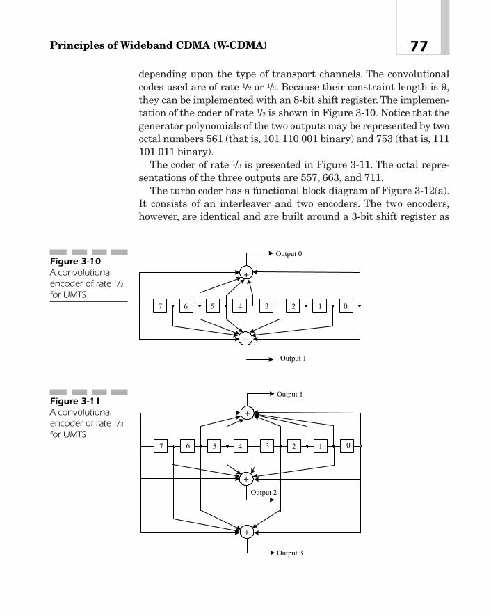
depending upon the type of transport channels. The convolutionalcodes used are of rate 1/2 or 1/3. Because their constraint length is 9,they can be implemented with an 8-bit shift register. The implemen-tation of the coder of rate 1/2 is shown in Figure 3-10. Notice that thegenerator polynomials of the two outputs may be represented by twooctal numbers 561 (that is, 101 110 001 binary) and 753 (that is, 111101 011 binary).
The coder of rate 1/3 is presented in Figure 3-11. The octal repre-sentations of the three outputs are 557, 663, and 711.
The turbo coder has a functional block diagram of Figure 3-12(a).It consists of an interleaver and two encoders. The two encoders,however, are identical and are built around a 3-bit shift register as
77Principles of Wideband CDMA (W-CDMA)
+
+
27
Output 0
Output 1
1 03456
Figure 3-10A convolutionalencoder of rate 1/2
for UMTS
+
+
+
1234567 0
Output 1
Output 2
Output 3
Figure 3-11A convolutionalencoder of rate 1/3
for UMTS
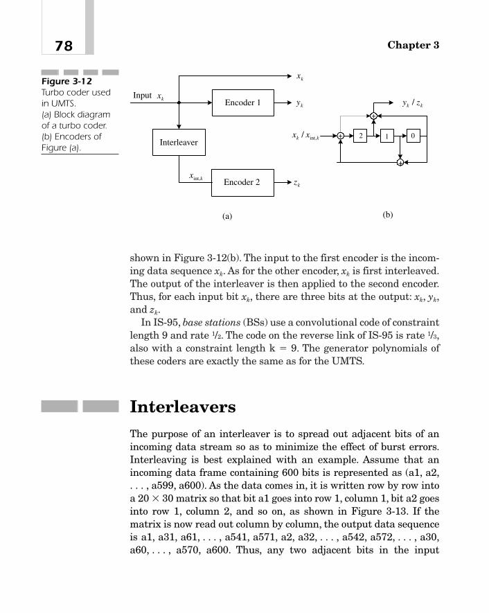
shown in Figure 3-12(b). The input to the first encoder is the incom-ing data sequence xk. As for the other encoder, xk is first interleaved.The output of the interleaver is then applied to the second encoder.Thus, for each input bit xk, there are three bits at the output: xk, yk,and zk.
In IS-95, base stations (BSs) use a convolutional code of constraintlength 9 and rate 1/2. The code on the reverse link of IS-95 is rate 1/3,also with a constraint length k � 9. The generator polynomials ofthese coders are exactly the same as for the UMTS.
InterleaversThe purpose of an interleaver is to spread out adjacent bits of anincoming data stream so as to minimize the effect of burst errors.Interleaving is best explained with an example. Assume that anincoming data frame containing 600 bits is represented as (a1, a2,. . . , a599, a600). As the data comes in, it is written row by row intoa 20 � 30 matrix so that bit a1 goes into row 1, column 1, bit a2 goesinto row 1, column 2, and so on, as shown in Figure 3-13. If thematrix is now read out column by column, the output data sequenceis a1, a31, a61, . . . , a541, a571, a2, a32, . . . , a542, a572, . . . , a30,a60, . . . , a570, a600. Thus, any two adjacent bits in the input
Chapter 378
Encoder 1
Encoder 2
Interleaver
Input kx
kx
ky
kz
2 1 0
+
+
+
kxint,
kk xx int,/
kk zy /
(a) (b)
Figure 3-12Turbo coder usedin UMTS. (a) Block diagramof a turbo coder.(b) Encoders ofFigure (a).

sequence are interleaved by 29 bits in the output stream. The inter-leaver span is the total number of bits in the block which are inter-leaved, or an equivalent time period. For example, in this case, thespan is 600 bits.
In UMTS, interleaving is done in two steps. First, each transportblock, after channel coding, is interleaved in the first interleaver.Here, the interleaver matrix (that is, Figure 3-13) may have 1, 2, 4,or 8 columns, depending upon the Transmission Time Interval (TTI)(that is, 10, 20, 40, or 80 ms). When there are 4 or 8 columns, they arefirst permuted in a certain order before reading out the matrix. Forexample, if there are 4 columns, columns 2 and 3 are interchanged.
After the first interleaver, transport channels are mapped to phys-ical channels. The data associated with each physical channel ispassed through the second interleaver, where the number ofcolumns is fixed at 30. Clearly, the number of rows depends on thenumber of bits in a frame. If the number of incoming data bits is notan integral multiple of 30, the last row is padded with dummy bits.The columns of the matrix are permuted in a specific order and thenread out from left to right. The dummy bits are removed from theoutput before it is spread by a channelization code.
ModulationThe basic idea of modulation is to vary some characteristic propertyof a radio frequency (RF) signal, such as its amplitude, frequency, or
79Principles of Wideband CDMA (W-CDMA)
a1
a31
o
o
a571
a2
a32
o
o
a572
o o o
o o o
o o o
o o o
o o o
a30
a60
o
o
a600
Figure 3-13A block interleaver

phase, by the digital signal to be transmitted. The incoming serialdata is first mapped into a sequence of symbols. The number of bitsper symbol may vary depending on the type of modulation. The sim-plest modulation scheme is BPSK. Here each symbol consists of anincoming bit, and the phase of the carrier is changed by 0 degrees ifthe symbol is a zero and by 180 degrees if the symbol is a one. InQPSK, each pair of incoming data bits constitutes a symbol. Thephase of the carrier is altered according to the symbol. For example,in one possibility, the carrier phase is advanced by 0 degrees if thesymbol is (0,0), by 90 degrees if the symbol is (0,1), by 180 degrees ifthe symbol is (1,1), and by 270 degrees if the symbol is (1,0). In digi-tal cellular systems, QPSK is used. This is usually implemented bydividing the incoming data into two sequences—one with the oddbits and the other with the even bits. Each of these sequences thenBPSK-modulates the carrier [12]. The block diagram of a QPSKmodulator is shown in Figure 3-14. See Appendix B for more detail.
Demodulation of a Phase Modulated Signal
There are two types of demodulation—coherent and differential.With coherent detection, the receiver needs to know the absolutephase angle of the transmitter carrier. In differential detection, onthe other hand, it is not necessary to know this absolute phase angle.All that is required here is the relative phase angle of the carrierduring successive symbol periods. In this case, however, the receiver
Chapter 380
SymbolMapper
Data
Pulse-ShapingFilter X
X
I
Q
A Cos tc c
A Sin tc c
OutputSerial-to-Parallel
Converter
Even Bits
Odd Bits
Pulse-ShapingFilter
Σ
ω
ω
Figure 3-14Functional blockdiagram of a QPSKmodulator used indigital cellularsystems

performance degrades to some extent. For example, this degradationis about 2 dB for BPSK or QPSK.7
If the channel noise is Gaussian, coherent detection gives the bestperformance. Under these circumstances, BPSK and QPSK havealmost identical bit error rate performance. This is shown in Figure3-15 [13]. However, the bandwidth required in QPSK is about onehalf of that for BPSK. To be more specific, if Rb is the data rate, thebandwidth with BPSK using rectangular pulses is 2Rb. If rectangu-lar pulses are passed through a raised cosine, pulse-shaping filter,almost all of the power spectral density is contained in a bandwidthof 1.5Rb around the carrier frequency. With QPSK, the null-to-nullbandwidth is Rb when using rectangular pulses and about 0.75Rb
with a raised cosine filter.
81Principles of Wideband CDMA (W-CDMA)
7In other words, the SNR required to achieve the same bit error rate is 2 dB more forthe differential detection.
-10 -8 -6 -4 -2 0 2 4 6 810-4
10-3
10-2
10-1
100
Signal-to-Noise Ratio (dB)
Bit
Err
or R
ate
Figure 3-15The bit error rateperformance ofBPSK with coherentdetection in thepresence ofGaussian noise
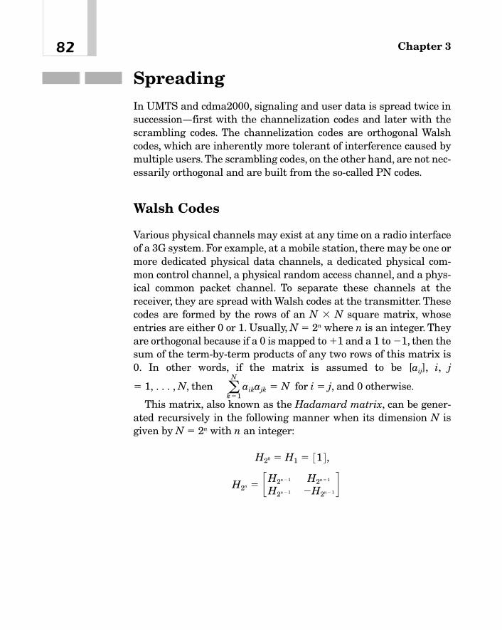
SpreadingIn UMTS and cdma2000, signaling and user data is spread twice insuccession—first with the channelization codes and later with thescrambling codes. The channelization codes are orthogonal Walshcodes, which are inherently more tolerant of interference caused bymultiple users. The scrambling codes, on the other hand, are not nec-essarily orthogonal and are built from the so-called PN codes.
Walsh Codes
Various physical channels may exist at any time on a radio interfaceof a 3G system. For example, at a mobile station, there may be one ormore dedicated physical data channels, a dedicated physical com-mon control channel, a physical random access channel, and a phys-ical common packet channel. To separate these channels at thereceiver, they are spread with Walsh codes at the transmitter. Thesecodes are formed by the rows of an N � N square matrix, whoseentries are either 0 or 1. Usually, N � 2n where n is an integer. Theyare orthogonal because if a 0 is mapped to �1 and a 1 to �1, then thesum of the term-by-term products of any two rows of this matrix is0. In other words, if the matrix is assumed to be [aij], i, j
� 1, . . . , N, then for i � j, and 0 otherwise.
This matrix, also known as the Hadamard matrix, can be gener-ated recursively in the following manner when its dimension N isgiven by N � 2n with n an integer:
H2n � cH2n � 1 H2n � 1
H2n � 1 �H2n � 1d
H20 � H1 � 31 4 ,
aN
k�1 aikajk � N
Chapter 382
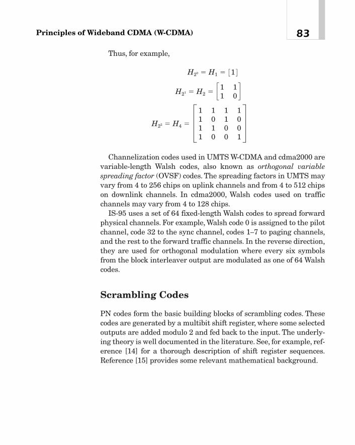
Thus, for example,
Channelization codes used in UMTS W-CDMA and cdma2000 arevariable-length Walsh codes, also known as orthogonal variablespreading factor (OVSF) codes. The spreading factors in UMTS mayvary from 4 to 256 chips on uplink channels and from 4 to 512 chipson downlink channels. In cdma2000, Walsh codes used on trafficchannels may vary from 4 to 128 chips.
IS-95 uses a set of 64 fixed-length Walsh codes to spread forwardphysical channels. For example, Walsh code 0 is assigned to the pilotchannel, code 32 to the sync channel, codes 1—7 to paging channels,and the rest to the forward traffic channels. In the reverse direction,they are used for orthogonal modulation where every six symbolsfrom the block interleaver output are modulated as one of 64 Walshcodes.
Scrambling Codes
PN codes form the basic building blocks of scrambling codes. Thesecodes are generated by a multibit shift register, where some selectedoutputs are added modulo 2 and fed back to the input. The underly-ing theory is well documented in the literature. See, for example, ref-erence [14] for a thorough description of shift register sequences.Reference [15] provides some relevant mathematical background.
H22 � H4 � ≥1 1 1 11 0 1 01 1 0 01 0 0 1
¥
H21 � H2 � c1 11 0 d
H20 � H1 � 31 4
83Principles of Wideband CDMA (W-CDMA)

Theory of PN Codes To illustrate the principle of PN codes, con-sider Figure 3-16. The shift register array consists of four single-bitshift registers and is clocked at the chip rate. The outputs of regis-ters 3 and 0 are added in a modulo-2 adder (that is, an exclusive-ORcircuit), and then applied to the input of the array.
Assume that the initial states of all stages of the shift register are1, 1, 1, and 1. Then at instant t � 0, the output of the adder is 0. Sowhen the first clock pulse appears, the states of the 4-bit shift regis-ter change to 0, 1, 1, and 1, respectively. Thus, the states with suc-cessive clock pulses are
1 1 1 1
0 1 1 1
1 0 1 1
0 1 0 1
1 0 1 0
1 1 0 1
0 1 1 0
0 0 1 1
1 0 0 1
0 1 0 0
0 0 1 0
0 0 0 1
1 0 0 0
1 1 0 0
1 1 1 0
1 1 1 1
Chapter 384
+
3 2 1 0 OutputFigure 3-16A 4-stage shiftregister togenerate a PN code
TEAMFLY
Team-Fly®

There is no need to write the output sequence any more becausethe pattern repeats after every 15 clock pulses. The output may betaken from any one of the four registers. When taken from register0, the output sequence is 1 1 1 1 0 1 0 1 1 0 0 1 0 0 0 . . . . The samesequence, with some delays, will be generated with any other initialstates as long as they are not all 0’s.
A few things are to be noticed here. First, the output sequence isperiodic, but its bit pattern is random. Thus, it may be termed apseudo-random pattern. In this example, the sequence repeats itselfafter 15 clock pulses. In other words, its period is 15 or 24 � 1, themaximum that can be achieved with a 4-bit shift register.A sequencewith the longest possible period that can be generated with a givenshift register is called a maximal sequence or a maximum-lengthsequence.The second point to observe is that in each period, there areeight 1’s and seven 0’s. In other words, the numbers of 1’s and 0’s areequal within one clock period. Third, this particular output sequencehas one run of length 4, one run of length 3, two runs of length 2, andfour runs of length 1.
Some shift register sequences, finite as they are, may have all ofthe following randomness properties [14]:
1. In any given period, the number of 1’s is equal to the number of0’s within one bit.
2. Each period of the output sequence contains runs of differentlengths. In a random sequence, one half of these runs are oflength 1, one fourth of length 2, one eighth of length 4, and so on.
3. The auto-correlation function C(j) of a peroidic sequence {bn} ofperiod N is defined by
(3-5)
In other words, it is the sum of the products of the elements of thesequence and its delayed copy. Assuming that each bi is either �1 or�1, the auto-correlation function C(j) of the shift register sequencehas only two values:
(3-6)C1j 2 � eN if j � 0K if 0 6 j 6 N
C1j 2 �aN
i�1bibi�j
85Principles of Wideband CDMA (W-CDMA)
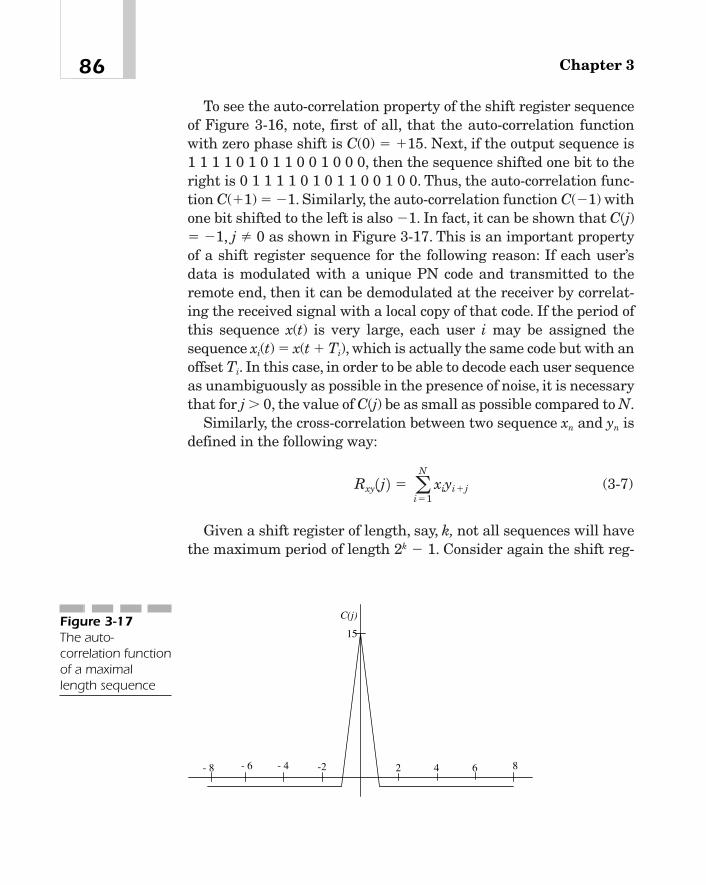
To see the auto-correlation property of the shift register sequenceof Figure 3-16, note, first of all, that the auto-correlation functionwith zero phase shift is C(0) � �15. Next, if the output sequence is1 1 1 1 0 1 0 1 1 0 0 1 0 0 0, then the sequence shifted one bit to theright is 0 1 1 1 1 0 1 0 1 1 0 0 1 0 0. Thus, the auto-correlation func-tion C(�1) � �1. Similarly, the auto-correlation function C(�1) withone bit shifted to the left is also �1. In fact, it can be shown that C(j)� �1, j 0 as shown in Figure 3-17. This is an important propertyof a shift register sequence for the following reason: If each user’sdata is modulated with a unique PN code and transmitted to theremote end, then it can be demodulated at the receiver by correlat-ing the received signal with a local copy of that code. If the period ofthis sequence x(t) is very large, each user i may be assigned thesequence xi(t) � x(t � Ti), which is actually the same code but with anoffset Ti. In this case, in order to be able to decode each user sequenceas unambiguously as possible in the presence of noise, it is necessarythat for j � 0, the value of C(j) be as small as possible compared to N.
Similarly, the cross-correlation between two sequence xn and yn isdefined in the following way:
(3-7)
Given a shift register of length, say, k, not all sequences will havethe maximum period of length 2k � 1. Consider again the shift reg-
Rxy1j 2 � aN
i�1xiyi�j
Chapter 386
2 4 6 8-2- 4- 6- 8
C(j)
15Figure 3-17The auto-correlation functionof a maximallength sequence
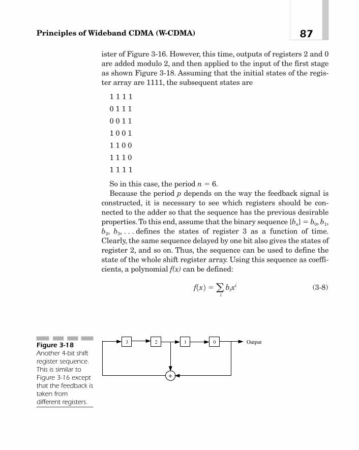
ister of Figure 3-16. However, this time, outputs of registers 2 and 0are added modulo 2, and then applied to the input of the first stageas shown Figure 3-18. Assuming that the initial states of the regis-ter array are 1111, the subsequent states are
1 1 1 1
0 1 1 1
0 0 1 1
1 0 0 1
1 1 0 0
1 1 1 0
1 1 1 1
So in this case, the period n � 6.Because the period p depends on the way the feedback signal is
constructed, it is necessary to see which registers should be con-nected to the adder so that the sequence has the previous desirableproperties. To this end, assume that the binary sequence {bn} � b0, b1,b2, b3, . . . defines the states of register 3 as a function of time.Clearly, the same sequence delayed by one bit also gives the states ofregister 2, and so on. Thus, the sequence can be used to define thestate of the whole shift register array. Using this sequence as coeffi-cients, a polynomial f(x) can be defined:
(3-8)f1x 2 �ai
bixi
87Principles of Wideband CDMA (W-CDMA)
+
3 2 1 0 OutputFigure 3-18Another 4-bit shiftregister sequence.This is similar toFigure 3-16 exceptthat the feedback istaken fromdifferent registers.

In this case, we can determine a function
(3-9)
such that where the division by g(x) is modulo 2. In
other words, the shift register sequence f(x) can be generated by con-structing a feedback signal by adding (modulo 2) the outputs of thek shift registers according to the function g(x). Function g(x) is calledthe characteristic polynomial for sequence bn. Clearly, in the previousdefinition of g(x), gi may be 0 for some values of i.
We will now provide some important results without giving anyproof:
1. Given a function g(x) as defined previously, the period of a k-stage shift register sequence is the smallest positive integer nfor which g(x) divides polynomial 1 � xn. The maximum possibleperiod of a k-stage shift register is 2k � 1.
2. If the feedback in a k-stage shift register is such that the outputsequence has indeed this maximum period 2k � 1, then thefunction g(x) that generates this sequence is irreducible. In otherwords, g(x) is divisible only by itself (and of course by 1).Reference [14] lists a few irreducible polynomials.
Notice that this statement merely gives a necessary condition forthe sequence to be maximal length. This condition is notsufficient because there are polynomials that are irreducible, butdo not yield a maximal length sequence. For example, considerg(x) � 1 � x � x2 � x3 � x4. This polynomial is irreducible, butbecause it divides 1 � x5, the period of the sequence is 5 and not 24 � 1.
3. The period of a k-stage shift register sequence is a factor of 2k � 1. Thus, if 2k � 1. is a prime, then every irreduciblepolynomial of degree k will generate a maximal lengthsequence.
To illustrate these ideas with examples, consider the shift registerof Figure 3-16. Here, the shift register consists of four stages. Thus
f1x 2 �1
g1x 2 ,
g1x 2 � 1 � ak
i�1gixi
Chapter 388

k � 4. Because the outputs from registers 3 and 0 are being addedand then applied to the input, the characteristic polynomial is
(3-10)
The period is 15, the maximum achievable with four registers. Itcan be shown that the smallest positive integer n for which this g(x)divides 1 � xn is indeed 15, thus satisfying statement 1 previously.Furthermore, as required by statement 2, it can be easily shown thatg(x) is in fact irreducible because it cannot be factored into polyno-mials of lower degrees. But because 15 is not a prime, followingstatement 3, not all irreducible polynomials of degree 4 will generatea maximal length sequence.
Referring to Figure 3-18, the characteristic polynomial for thisshift register sequence is
(3-11)
It can be shown that this polynomial divides 1 � x6. Thus, theperiod of this sequence is n � 6, as shown previously. Also, this char-acteristic polynomial is not irreducible because 1 � x2 � x4 � (1 � x� x2)2, and hence, in accordance with statement 2 previously, cannotgenerate a maximal length sequence.
Scrambling Codes in UMTS The scrambling codes in UMTS arecomplex valued and may be either long or short. A long code has alength of 38,400 chips (that is, 10 ms) and a short code only 256chips. As an example, Figure 3-19 shows how a long code for a UMTSuplink channel is generated [12]. This code is constructed with twoPN codes, whose characteristic polynomials are g1(x) � x25 � x3 � 1and g2(x) � x25 � x3 � x2 � x � 1. They are implemented as sequencesPN1 and PN2 using two 25-bit shift registers. PN1 and PN2 areadded modulo 2, and the output is mapped to a real-valued function,say, I. Another function Q is derived by simply delaying I by 224 � 16chips. Q is multiplied by �j, where the sign changes every chipperiod, and then added to I to yield the long code.
g1x 2 � x4 � x2 � 1
g1x 2 � x4 � x3 � 1
89Principles of Wideband CDMA (W-CDMA)
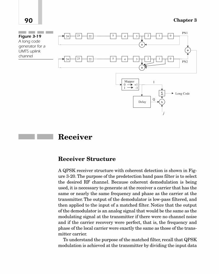
Receiver
Receiver Structure
A QPSK receiver structure with coherent detection is shown in Fig-ure 3-20. The purpose of the predetection band pass filter is to selectthe desired RF channel. Because coherent demodulation is beingused, it is necessary to generate at the receiver a carrier that has thesame or nearly the same frequency and phase as the carrier at thetransmitter. The output of the demodulator is low-pass filtered, andthen applied to the input of a matched filter. Notice that the outputof the demodulator is an analog signal that would be the same as themodulating signal at the transmitter if there were no channel noiseand if the carrier recovery were perfect, that is, the frequency andphase of the local carrier were exactly the same as those of the trans-mitter carrier.
To understand the purpose of the matched filter, recall that QPSKmodulation is achieved at the transmitter by dividing the input data
Chapter 390
+
3 2 014524 23 22
+
3 2 014524 23 22
+
x
�
Mapper0 +11 -1
Delay
Long Code
j
PN1
PN2
I
Q
Figure 3-19A long codegenerator for aUMTS uplinkchannel
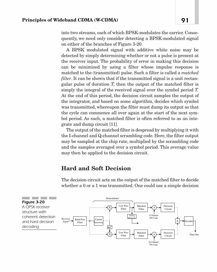
into two streams, each of which BPSK-modulates the carrier. Conse-quently, we need only consider detecting a BPSK-modulated signalon either of the branches of Figure 3-20.
A BPSK modulated signal with additive white noise may bedetected by simply determining whether or not a pulse is present atthe receiver input. The probability of error in making this decisioncan be minimized by using a filter whose impulse response ismatched to the (transmitted) pulse. Such a filter is called a matchedfilter. It can be shown that if the transmitted signal is a unit rectan-gular pulse of duration T, then the output of the matched filter issimply the integral of the received signal over the symbol period T.At the end of this period, the decision circuit samples the output ofthe integrator, and based on some algorithm, decides which symbolwas transmitted, whereupon the filter must dump its output so thatthe cycle can commence all over again at the start of the next sym-bol period. As such, a matched filter is often referred to as an inte-grate and dump circuit [11].
The output of the matched filter is despread by multiplying it withthe I-channel and Q-channel scrambling code. Here, the filter outputmay be sampled at the chip rate, multiplied by the scrambling codeand the samples averaged over a symbol period. This average valuemay then be applied to the decision circuit.
Hard and Soft Decision
The decision circuit acts on the output of the matched filter to decidewhether a 0 or a 1 was transmitted. One could use a simple decision
91Principles of Wideband CDMA (W-CDMA)
Band PassFilter
MatchedFilter
CarrierRecovery
TimingRecovery
DecisionCircuitX
Low PassFilter
MatchedFilter
DecisionCircuitX
Low PassFilter
900
Σ
Demodulator
x
x
I-ChannelPN Code
Q-ChannelPN Code
ReceivedSignal Decoder
Data Out
Figure 3-20A QPSK receiverstructure withcoherent detectionand hard decisiondecoding
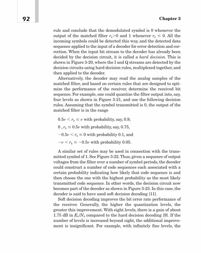
rule and conclude that the demodulated symbol is 0 whenever theoutput of the matched filter rk�0 and 1 whenever rk � 0. All theincoming symbols could be detected this way, and the detected datasequence applied to the input of a decoder for error detection and cor-rection. When the input bit stream to the decoder has already beendecided by the decision circuit, it is called a hard decision. This isshown in Figure 3-20, where the I and Q streams are detected by thedecision circuits using hard decision rules, multiplexed together, andthen applied to the decoder.
Alternatively, the decoder may read the analog samples of thematched filter, and based on certain rules that are designed to opti-mize the performance of the receiver, determine the received bitsequence. For example, one could quantize the filter output into, say,four levels as shown in Figure 3-21, and use the following decisionrules. Assuming that the symbol transmitted is 0, the output of thematched filter is in the range
0.5n rk � n with probability, say, 0.9,
0 , rk � 0.5n with probability, say, 0.75,
�0.5n rk � 0 with probability 0.1, and
�n rk � �0.5n with probability 0.05.
A similar set of rules may be used in connection with the trans-mitted symbol of 1. See Figure 3-22.Thus, given a sequence of outputvoltages from the filter over a number of symbol periods, the decodercould construct a number of code sequences each associated with acertain probability indicating how likely that code sequence is andthen choose the one with the highest probability as the most likelytransmitted code sequence. In other words, the decision circuit nowbecomes part of the decoder as shown in Figure 3-23. In this case, thedecoder is said to have used soft decision decoding [11].
Soft decision decoding improves the bit error rate performance ofthe receiver. Generally, the higher the quantization levels, thegreater this improvement. With eight levels, there is a gain of about1.75 dB in Eb /N0 compared to the hard decision decoding [9]. If thenumber of levels is increased beyond eight, the additional improve-ment is insignificant. For example, with infinitely fine levels, the
Chapter 392

gain in Eb /N0 is only 2 dB. Thus, for all practical purposes, eight oreven four levels are sufficient.
Viterbi Decoding
The Viterbi algorithm for decoding convolutional codes has beenstudied extensively in the literature [8]—[11]. The algorithm hasbeen shown to be the maximum likelihood and is particularly use-ful for decoding convolutional codes of small constraint lengths.
93Principles of Wideband CDMA (W-CDMA)
Band PassFilter
MatchedFilter
SoftDecisionDecoder
XLow Pass
Filter x
PN Code
ReceivedSignal
CarrierRecovery
Data OutFigure 3-23Receiver with softdecision decoding
0 +v+0.5v-v -0.5vFigure 3-21Four-levelquantization of the input to thedecision circuit
1
1
0
QuantizationLevel
2
3
4
TransmittedBit
Prob{Quantization Level|Transmitted Bit = x}
0. 9
0. 75
0. 1
0. 05 0. 9
0. 75
0. 1
0. 05
Figure 3-22Transitionprobabilities in softdecision decodingwith four levels ofquantization. As anexample, theprobability that thematched filteroutput has aquantization level1, assuming thatthe transmitted bitis a 0, is 0.9.
Appendix A gives a brief description of this algorithm using softdecision decoding.
Multipath Diversity in CDMAWider bandwidths offer some advantages that are not available withnarrowband systems. One of them is reduced fading, and the other isconcerned with multipath diversity. As described previously, the sig-nal received at a mobile antenna consists of a number of reflectedrays, each characterized by a different amount of attenuation anddelay. As a vehicle moves around, the attenuation and delay associ-ated with each path also change with time. As a result, the receivedsignal is time varying in nature. If the signal bandwidth is small com-pared to the coherence bandwidth of the channel, different frequencycomponents of the signal have identical statistics and tend to varywith time in the same manner. The result is that they interfere witheach other, causing correlated signal fading. This kind of fading iscalled flat fading. If, on the other hand, the signal bandwidth is large,as in W-CDMA, compared to the coherence bandwidth of the channel,the different frequency components of the signal still interfere witheach other, but now they are statistically independent, and therefore,their variations are not correlated with respect to each other.The fad-ing that results from this situation is called frequency selective fading.In this case, if one frequency component is below the average level ofthe signal, another component is likely to be above that level, and so,the net effect would be a reduction in fade [31]. This is shown in Fig-ure 3-24 where the term fade depth is defined as the amount bywhich the signal falls below its average value with a probability of0.1. If the channel bandwidth is only 30 kHz as in cellular systemTIA-553, the signal goes into a �10 dB fade with probability 0.1. Onthe other hand, in cdmaOne, where the bandwidth is 1.25 MHz, thesignal encounters a �8.75 dB, whereas in W-CDMA with a band-width of 5 MHz, the signal experiences a �5.75 dB fade with thesame probability. Thus, fading is reduced with increased bandwidth.
When the signal bandwidth is sufficiently large, and multipathcomponents are delayed by more than a chip period, they can be
Chapter 394
TEAMFLY
Team-Fly®

treated as multiple copies of the same signal, and may, therefore, becombined constructively in a diversity receiver as discussed in thefollowing section.
Rake Receiver
Studies of power delay profiles of urban and dense urban areasaround 900 MHz indicate that most of the energy of the received sig-nal is due to the reflected rays with delays in excess of 0.75 ms. In W-CDMA, because the chip period is quite small (about 0.2604 ms for achip rate of 3.84 Mc/s) compared to the delay spread, multipath com-ponents with delays of more than one chip period may have signifi-cant energy. Thus, if the signal bandwidth is greater than thecoherence bandwidth of the channel, the various multipath compo-nents can be used as different branches of a diversity receiver. This,
95Principles of Wideband CDMA (W-CDMA)
0 2 4 6 8 10 12 14 16 18 202
3
4
5
6
7
8
9
10
Fade
Dep
th (
dB)
Bandwidth (MHz)
Figure 3-24The effect ofchannelbandwidth onfading. Here, fadedepth is defined asthe amount bywhich the signalfalls below itsaverage value witha probability of 0.1.

in essence, forms the basis of a rake receiver [17], [18], [21], [32], [33].Each branch of the receiver is called a finger.
Because the autocorrelation of a PN code across successive chipperiods is very small, that is, R(nt) is very small for n� 0 comparedto its value for n � 0, copies of the desired signal can be extracted iftheir associated delays are multiples of the chip period. Theextracted components may then be combined in an optimal mannerso that fading is reduced and, consequently, the bit error rate perfor-mance of the receiver improved. Notice that these delays, althoughgreater than the chip period, must at the same time be sufficientlysmall compared to the bit period; otherwise, there may be significantintersymbol interference.
Suppose for illustrative purposes that Figure 3-25 represents thepower delay profile of an urban area. Here, two distinct paths areidentifiable, one with a delay spread from 0 to t1 and the other fromt1 to t2. If the delay spreads are greater than the chip period, the twopaths can be resolved and taken advantage of in the receiver. Thefunctional block diagram of a rake receiver is shown in Figure 3-26.After coherent demodulation, the I-channel and Q-channel signalsare multiplied by their respective PN codes. The outputs aI and aQ
are added in quadrature and multiplied by the user-specific PN code.For each branch of the receiver, there is a matched filter, which inte-grates the input signal over a period that depends on the delayspread of the associated branch. For example, starting at any sym-bol, say, nT, where n is an integer and T is the symbol period, thefirst branch is integrated from nT to (n � 1)T, the second branchfrom nT � t1 to (n � 1)T � t1, and so on. The matched filters are
Chapter 396
Rel
ativ
e Po
wer
Den
sity
Delay�1 �2
�
Figure 3-25An example powerdelay profile usedin a rake receiver

designed to yield the maximum SNR in the presence of Gaussiannoise. Outputs of the filter banks are each weighted by gain ai,summed together in the block marked Diversity Combiner andapplied to the decision circuit where symbols are decoded.
The gain coefficients ai may be either fixed, or dynamicallyadjusted, as shown in Figure 3-26, using an appropriate diversity-combining algorithm. For example, in an equal-gain combiner, coef-ficients ai for all paths are equal and set to a constant value.Alternatively, in a maximal ratio-combining scheme, each gain ai isadjusted so that it is proportional to the signal-to-noise-power ratioof the associated branch. When the gains are adjusted this way, anoptimum SNR value of the receiver is obtained. Because a channelcan be modeled as a tapped delay line, it is found that in this case,coefficient ai for any branch is the complex conjugate of the channelcoefficient of the associated path.8 Because the channel is usuallytime varying, it is necessary to track and estimate the channel peri-odically. This can be accomplished either by regularly sending aknown pattern from the transmitter (as in IS-136) or by means of anauxiliary pilot, as in W-CDMA.
97Principles of Wideband CDMA (W-CDMA)
900BPF
LPF
LPF
XX
X X
ReceivedSignal
I ChannelPN Code
Q ChannelPN Code
2
1
DiversityCombiner
DecisionCircuit
Output
MatchedFilter
Ia
Qa oo
oo
X
User Code
)cos( θω +tA c
∫+ Tn
nT
)1(
∫++
+
1
1
)1( τ
τ
Tn
nT
α
αΣ
Figure 3-26Functional blockdiagram of a rake receiver for W-CDMA
8Based on its impulse response, a channel can be modeled as a tapped delay line. Thenumber of taps depends upon the degree of accuracy required. The power delay pro-file of this example suggests that two taps are sufficient for this channel.

The maximum amount of multipath delay that can be exploited ina rake receiver is usually limited, and is determined by the powerdelay profile. As an example, for a city like New York, it lies in therange of 0.25—2.5 ms. Thus, in UMTS W-CDMA, where the chip rateis 3.84 Mc/s, the delay is about 1—10 chips.
Although multipath diversity is a property of all CDMA systems,it is only W-CDMA that provides multipath diversity for small cells(that is, the micro and pico cells). To see this, consider IS-95 wherethe carrier bandwidth is 1.25 MHz. In this case, because the chiprate is 1.2288 Mc/s and because the delay must be at least one chiplong to achieve multipath diversity, the difference in path lengthsmust be at least 244 meters. On the other hand, for W-CDMA with 5MHz bandwidth, the chip rate is 3.84 Mc/s, and so this path differ-ence is reduced to 81 meters.
The multipath diversity employed in a rake receiver leads to animprovement in performance. For example, the value of Eb /N0
required to ensure a bit error rate of 10�3 on a fading channel isabout 10 dB, assuming BPSK modulation, a 4-branch rake receiver,and equal gain combining. The required Eb /N0 for the same bit errorrate is 14 dB with two branches and about 24 dB with one branch,that is, without any multipath diversity [21].The maximal ratio com-bining has the best performance. If most of the signal energy is con-tained in only one branch, a conventional receiver will performbetter than a rake receiver that uses equal gain combining [33]because, in this case, branches with very little signal power will onlyadd to the noise.
Multiuser Detection
Consider the uplink transmissions in UMTS. Here, the user data onvarious physical channels (such as dedicated physical data channels,dedicated physical control channels, and so on) is first spread with achannelization code, and then scrambled with a user-specific PNcode. Because channelization codes are mutually orthogonal andthus more resistant to multiuser interference, the physical channelscan be correctly separated at the receiver with a high probability.The
Chapter 398
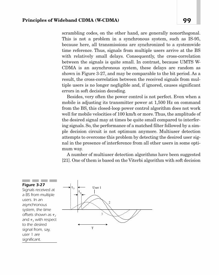
scrambling codes, on the other hand, are generally nonorthogonal.This is not a problem in a synchronous system, such as IS-95,because here, all transmissions are synchronized to a systemwidetime reference. Thus, signals from multiple users arrive at the BSwith relatively small delays. Consequently, the cross-correlationbetween the signals is quite small. In contrast, because UMTS W-CDMA is an asynchronous system, these delays are random asshown in Figure 3-27, and may be comparable to the bit period. As aresult, the cross-correlation between the received signals from mul-tiple users is no longer negligible and, if ignored, causes significanterrors in soft decision decoding.
Besides, very often the power control is not perfect. Even when amobile is adjusting its transmitter power at 1,500 Hz on commandfrom the BS, this closed-loop power control algorithm does not workwell for mobile velocities of 100 km/h or more. Thus, the amplitude ofthe desired signal may at times be quite small compared to interfer-ing signals. So, the performance of a matched filter followed by a sim-ple decision circuit is not optimum anymore. Multiuser detectionattempts to overcome this problem by detecting the desired user sig-nal in the presence of interference from all other users in some opti-mum way.
A number of multiuser detection algorithms have been suggested[21]. One of them is based on the Viterbi algorithm with soft decision
99Principles of Wideband CDMA (W-CDMA)
T
2 3τ User 1
2
3
τ
Figure 3-27Signals received ata BS from multipleusers. In anasynchronoussystem, the timeoffsets shown as t2
and t3 with respectto the desiredsignal from, say,user 1 aresignificant.

decoding. The ideas here are similar to those discussed in connectionwith the maximum likelihood decoding of convolutional codes [22],[23]. The received signal, after demodulation, is multiplied by thescrambling code of each user, integrated over a symbol period usinga matched filter, and applied to a soft decision decoder. The output ofthe matched filter corresponding to any desired user depends uponthe cross-correlation between the signal from that user and signalsfrom all other users over three consecutive symbol periods. Over agiven symbol length, the soft decision decoder considers all combi-nations of symbols from multiple users, and using a channel modeltogether with the observed outputs of the matched filter, estimatesthe likelihood of each sequence of symbols. Appendix C presents abrief description of this algorithm. Although the performance of thisreceiver is optimum, it is not very practical because the number ofreal-time computations required increases as 2n, where n is thenumber of users to be detected. A number of authors have proposedsuboptimum receiver structures where these computational require-ments are less stringent.
Another technique suggested for multiuser detection involves suc-cessive cancellation of interference from the received signal [24]—[28]. Here, the receiver first extracts the strongest signal of all usersand subtracts it from the received signal. Next, the second strongestsignal is detected from the remaining signal, and subtracted fromthis latter signal, and so on, until signals from all users have beendetected. The idea is illustrated in the block diagram of Figure 3-28.Because the performance of the receiver depends on the accuracywith which the strongest interference is detected in the first stage,reference [24] suggests using a multipath-combining receiver fordetecting the strongest interference.9 The detected data of this useris then passed through a channel model to regenerate a signal,which approximates as closely as possible the received signal fromthis user. The output of the channel model is subtracted from thereceived input. The result is used to derive the second strongest sig-nal in the same way. Conventional receivers may be used in the sec-ond and subsequent stages.
Chapter 3100
9For this to be possible, it is necessary that the signal bandwidth be much greater thanthe coherence bandwidth of the channel.
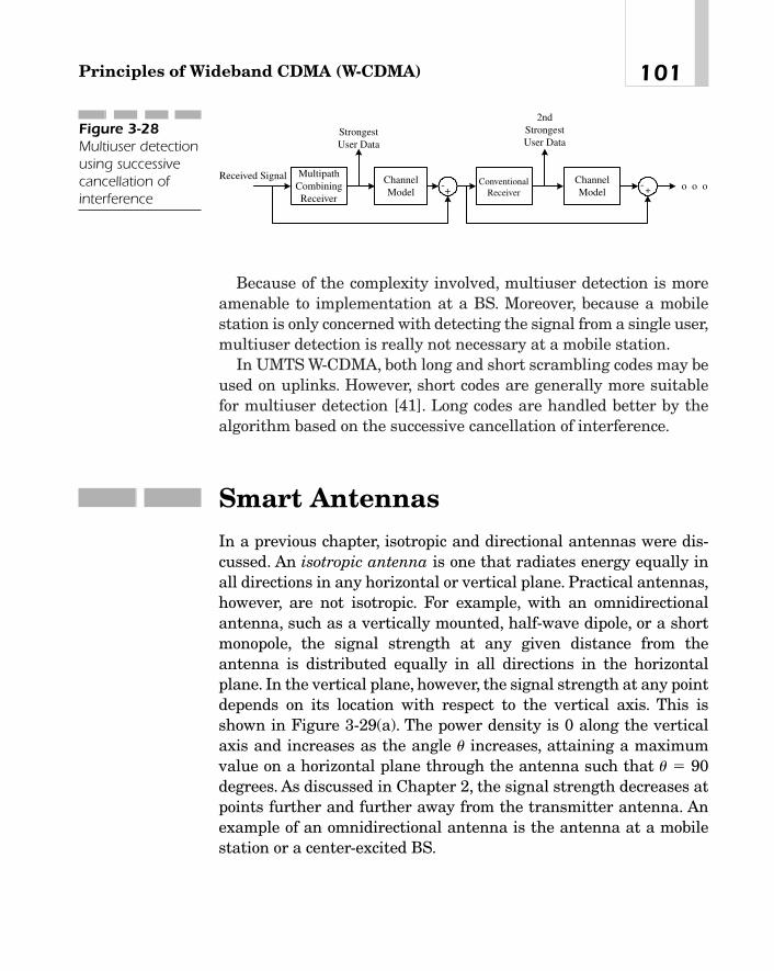
Because of the complexity involved, multiuser detection is moreamenable to implementation at a BS. Moreover, because a mobilestation is only concerned with detecting the signal from a single user,multiuser detection is really not necessary at a mobile station.
In UMTS W-CDMA, both long and short scrambling codes may beused on uplinks. However, short codes are generally more suitablefor multiuser detection [41]. Long codes are handled better by thealgorithm based on the successive cancellation of interference.
Smart AntennasIn a previous chapter, isotropic and directional antennas were dis-cussed. An isotropic antenna is one that radiates energy equally inall directions in any horizontal or vertical plane. Practical antennas,however, are not isotropic. For example, with an omnidirectionalantenna, such as a vertically mounted, half-wave dipole, or a shortmonopole, the signal strength at any given distance from theantenna is distributed equally in all directions in the horizontalplane. In the vertical plane, however, the signal strength at any pointdepends on its location with respect to the vertical axis. This isshown in Figure 3-29(a). The power density is 0 along the verticalaxis and increases as the angle u increases, attaining a maximumvalue on a horizontal plane through the antenna such that u � 90degrees. As discussed in Chapter 2, the signal strength decreases atpoints further and further away from the transmitter antenna. Anexample of an omnidirectional antenna is the antenna at a mobilestation or a center-excited BS.
101Principles of Wideband CDMA (W-CDMA)
StrongestUser Data
+-- +
Received Signal MultipathCombiningReceiver
ChannelModel
ConventionalReceiver
ChannelModel
2ndStrongestUser Data
o o o
Figure 3-28Multiuser detectionusing successivecancellation ofinterference
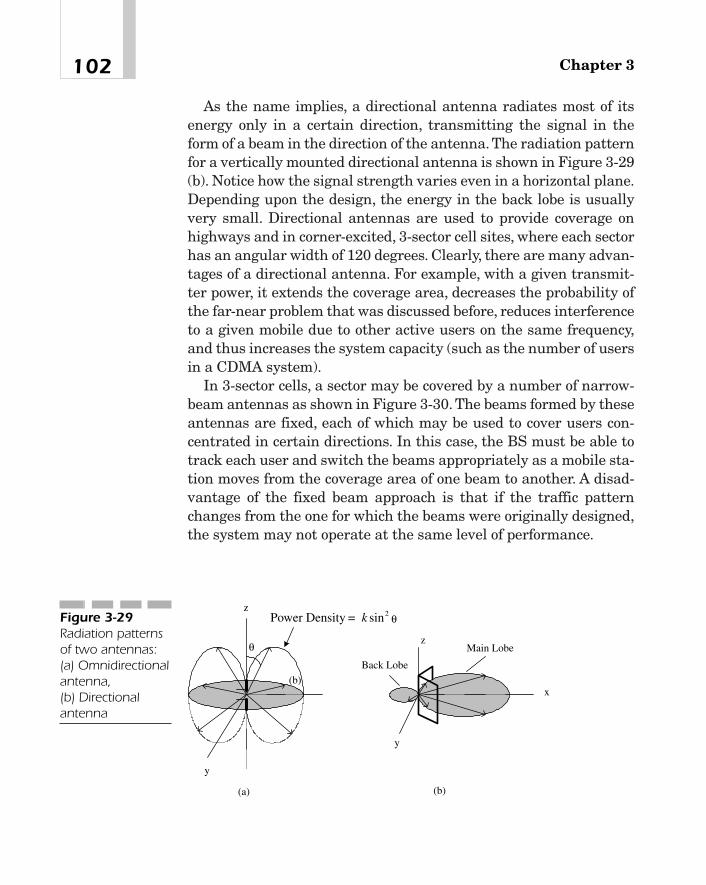
As the name implies, a directional antenna radiates most of itsenergy only in a certain direction, transmitting the signal in theform of a beam in the direction of the antenna. The radiation patternfor a vertically mounted directional antenna is shown in Figure 3-29(b). Notice how the signal strength varies even in a horizontal plane.Depending upon the design, the energy in the back lobe is usuallyvery small. Directional antennas are used to provide coverage onhighways and in corner-excited, 3-sector cell sites, where each sectorhas an angular width of 120 degrees. Clearly, there are many advan-tages of a directional antenna. For example, with a given transmit-ter power, it extends the coverage area, decreases the probability ofthe far-near problem that was discussed before, reduces interferenceto a given mobile due to other active users on the same frequency,and thus increases the system capacity (such as the number of usersin a CDMA system).
In 3-sector cells, a sector may be covered by a number of narrow-beam antennas as shown in Figure 3-30. The beams formed by theseantennas are fixed, each of which may be used to cover users con-centrated in certain directions. In this case, the BS must be able totrack each user and switch the beams appropriately as a mobile sta-tion moves from the coverage area of one beam to another. A disad-vantage of the fixed beam approach is that if the traffic patternchanges from the one for which the beams were originally designed,the system may not operate at the same level of performance.
Chapter 3102
Main Lobe
y
z
x
z
y
Power Density = k sin2
(a) (b)
(b)
Back Lobe
θ
θFigure 3-29Radiation patternsof two antennas:(a) Omnidirectionalantenna, (b) Directionalantenna

Because each mobile station has a unique physical location, thesignal received from each can be processed in real time and sepa-rated from the signals of all other users even though they may over-lap in the time or frequency domain. Signal processing required toperform this function is called spatial filtering or filtering in thespace domain. This technique is also called by some authors space-division multiple access (SDMA) because this enables multiple usersto be distinguished even though they may occupy the same fre-quency or time slot.
Clearly, sectorization of cells with directional antennas and use offixed beams may be considered as a form of spatial filtering.Another way to implement spatial filtering is to use an adaptiveantenna array where the signal received from each element of thearray is multiplied by a gain coefficient, called a weight, summedtogether, and then processed using digital signal processing tech-niques so as to maximize the system performance according to somecriteria. The weights are adjusted dynamically using an adaptationalgorithm that tries to achieve some design objectives. For example,an objective may be the formation of a beam in a desired directionso that the signal is maximized in that direction and minimized oreven reduced to a null in other directions, say, in the direction of co-channel sources. This is called digital beam forming. Another objec-tive may be the minimization of bit error rates for users located ina certain geographical area where the error rate would otherwise beexcessively high due to clutter or other conditions. The term smartantennas refers to both switched beam antennas and adaptiveantenna arrays.
103Principles of Wideband CDMA (W-CDMA)
y
x
λ / 2Figure 3-30Fixed beamsformed by narrow-beam antennas

Fundamental to the operation of adaptive antennas is the abilityto estimate the angle of arrival of signals from different users and,based on the estimate, steer the beams on downlink channels. Thearrival angle is generally quite well defined in rural areas, but not soin microcells or indoors. Because for large cells, the angle of arrivalvaries much more slowly than the instantaneous fading signal, mea-surements from mobile stations may also be used in the adaptationalgorithm.
The concept and theory of adaptive antennas may be found inReferences [35], [36]. Various authors have investigated the appli-cation of adaptive antennas to mobile communications systems[37]—[39], [42]. Reference [40] discusses the possibility of extendingthe capacity of an existing cellular system so as to serve areas ofhigh traffic density by using smart antennas. Possible benefits ofusing smart antennas in 3G systems have been studied under theauspices of the Technology in Smart Antennas for UniversalAdvanced Mobile Infrastructure (TSUNAMI) project in Europe [41],and include the following:
� Extending the range or coverage area in a desired direction withbeamforming
� Increasing the system capacity in areas with dense traffic (thatis, hot spots)
� Dynamically adjusting the coverage area (say, from 120 to 45degrees)
� Creating nulls to/from co-channel interferers so as to minimizethe co-channel interference
� Tracking individual mobile stations using separate, narrowbeams in their direction
� Reducing multipath fading
In this section, we will explain briefly how beam forming is accom-plished by adaptive antennas.
Figure 3-31(a) shows a functional block diagram of a systemwhere adaptive antennas are being used to maximize the signalfor a given user. Beam forming in a desired direction or creating anull (from co-channel interferers or various multipaths in a TDMAsystem) as shown in Figure 3-32 is similar in principle. Signals
Chapter 3104
TEAMFLY
Team-Fly®
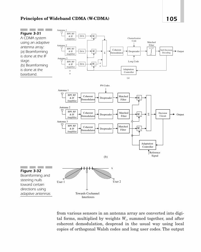
from various sensors in an antenna array are converted into digi-tal forms, multiplied by weights Wi, summed together, and aftercoherent demodulation, despread in the usual way using localcopies of orthogonal Walsh codes and long user codes. The output
105Principles of Wideband CDMA (W-CDMA)
Soft DecisionDecoding
Output
MatchedFilter
BPF, RF& IF
Amplifier1W
BPF, RF& IF
Amplifier2W
Antenna 1
Antenna 2
oo
AdaptationController
oo
CoherentDemodulator
Despreader
Long Code
ChannelizationCode
BPF, RF& IF
Amplifier3W
Antenna 3
D/A
D/A
D/A
∫+ Tn
nT
)1(
Σ
(a)
Figure 3-31A CDMA systemusing an adaptiveantenna array: (a) Beamforming is done at the IFstage. (b) Beamforming is done at thebaseband.
DecisionCircuit
Output
MatchedFilter
BPF, RF& IF
Amplifier1W
BPF, RF& IF
Amplifier2W
Antenna 1
Antenna 2
AdaptationController
CoherentDemodulator
Despreader
PN Codes
BPF, RF& IF
Amplifier3W
Antenna 3
CoherentDemodulator
Despreader
CoherentDemodulator
Despreader
MatchedFilter
MatchedFilter
ReferenceSignal
Σ
(b)
Towards CochannelInterferers
x
User 1 User 2
Figure 3-32Beamforming andsteering nullstoward certaindirections usingadaptive antennas

of the matched filter is decoded in a decision circuit. The resultingoutput is also used by the adaptation controller to adjust theweights so as to maximize the signal-to-interference ratio for thegiven user in much the same way as a rake receiver, discussedpreviously.
In this approach, because signals are being weighted and summedat the RF stage, the scheme suffers from the disadvantage that itsaccuracy is rather limited and that its implementation may becomequite complex, particularly when there are many elements in thearray. A scheme that performs beamforming at the baseband wasshown in Figure 3-31(b). Because signal processing is now beingdone at the baseband, it is possible to use 16-bit arithmetic comparedto a 5- or 6-bit operation that is usual for RF beamforming.
The improvement in performance with adaptive antennasdepends upon the antenna type—linear, planar, or circular—thenumber of elements in the array, and the spacing between adjacentelements. This spacing is usually one half of the carrier wavelength.The improvement in signal-to-interference ratios is about 3 dB withtwo elements, 6 dB with four elements, 7.75 dB with six elements,and 9 dB with eight elements [42].
SummaryIn this chapter we have presented fundamental principles of CDMAand more specifically W-CDMA. The various functional componentsof a BS transmitter have been discussed in some detail. The receiverstructure, soft decision decoding of convolutional codes, methods ofmultiuser detection at a BS, and smart antennas have beendescribed. In some cases, for the convenience of readers, details havebeen moved to the following appendices.
Chapter 3106
Appendix A—Viterbi Decoding of Convolutional CodesThe Viterbi algorithm performs sequential decoding using principlesof dynamic programming [9], [11]. The algorithm is based on the factthat if at any instant tk, there is a sequence of m information bits forwhich the decoder performance is optimum, then those m bits will bethe first m bits of a sequence that optimizes the performance at anylater instant tl � tk. Given a sequence of outputs from the matchedfilter over a desired observation period, a sequence of bits is chosenat each stage as the most likely transmitted sequence.
To continue with the algorithm, suppose that R is a sequence ofsamples of the matched filter output (which are analog voltages asmentioned before). At each symbol period, the number of samplesread by the decoder equals the number of output bits generated bythe encoder for each input bit. That is, for a rate 1/2 encoder, there aretwo samples to the input of the decoder at the end of each symbolperiod. Furthermore, each of these samples is defined by one of thequantization levels R. The maximum likelihood decision theorystates that X is the code that was most likely transmitted if the prob-ability of R (assuming X) is maximum, that is, if
To use this algorithm, then, it is first of all necessary to determinethe probability of occurrence of each quantization level of thedecoder inputs at each symbol period assuming that a transmittedbit is 0. Similarly, the probability of occurrence of each quantizationlevel of the decoder inputs at each symbol period, assuming that atransmitted bit is 1, is determined in the same manner. Becausethese probabilities will be used at each step for sequential decoding,
P1R 0 X 2 is maximum.
107Principles of Wideband CDMA (W-CDMA)
it is better to convert them into some suitable numbers that wouldspeed up the computation process. Specifically, suppose that
(A-1)
is the probability of occurrence of the j-th quantization level of thematched filter output at instant k, assuming that the transmitted bitis xkl, where xkl is either a 0 or 1 at any symbol period. As mentionedearlier, because an encoder of rate 1/2 generates two output bits foreach bit of the input, j takes only two values: 1 or 2, and so the prob-ability of a code symbol for a path in the trellis diagram is a productof two terms of type (A-1). In other words,
(A-2)
It is, therefore, convenient to take the logarithm of expression(A-2) and, for ease of computation, transform the result into an inte-ger using an appropriate expression. This value can then be used asa metric for a path. In this way, the branch metrics for all paths ofthe trellis diagram are computed.
For an encoder with m registers, the number of states for the trel-lis diagram is 2m�1. For instance, for the diagram of Figure 3-7, m �3, and the number of states is 4. Referring to the trellis diagram ofFigure 3-9, the Viterbi algorithm can be summarized in the followingway:
1. Starting at state 00 of Figure 3-17 (at depth 3 or beyond), addthe metrics of the two paths coming to this state to thepreviously saved metrics of the two states (namely 00 and 01)from which these two paths have originated.
2. Choose the larger of the two-path metrics computed in step 1and save it. This becomes the new path metric for this state (thatis, state 00) for subsequent use. The branch that gives the largerpath metric is called a survivor path. Identify this path byadding a 0 to the path history if state 00 has a larger metric.Otherwise, add 1 to the path history. This path history is savedin memory for use in the next step.
3. Repeat steps 1 and 2 for all other states at the same trellis depth.
Pk � p1rkl � xkl 2 � p1rk2 � xkl 2
p1rkj � xkl 2
Chapter 3108
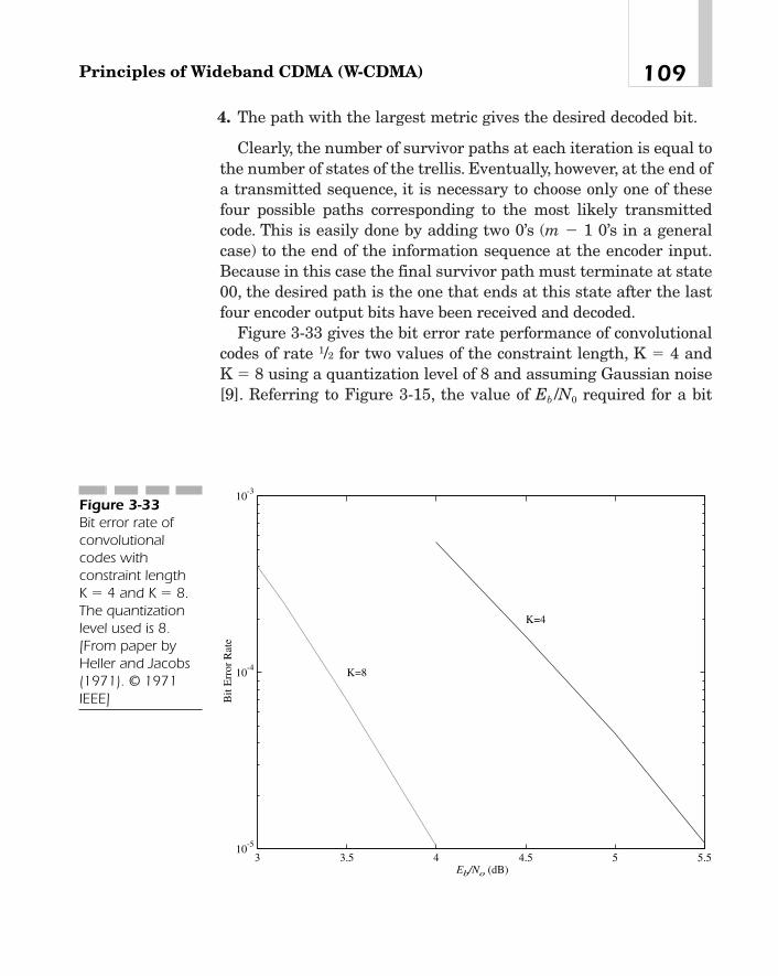
4. The path with the largest metric gives the desired decoded bit.
Clearly, the number of survivor paths at each iteration is equal tothe number of states of the trellis. Eventually, however, at the end ofa transmitted sequence, it is necessary to choose only one of thesefour possible paths corresponding to the most likely transmittedcode. This is easily done by adding two 0’s (m � 1 0’s in a generalcase) to the end of the information sequence at the encoder input.Because in this case the final survivor path must terminate at state00, the desired path is the one that ends at this state after the lastfour encoder output bits have been received and decoded.
Figure 3-33 gives the bit error rate performance of convolutionalcodes of rate 1/2 for two values of the constraint length, K � 4 andK � 8 using a quantization level of 8 and assuming Gaussian noise[9]. Referring to Figure 3-15, the value of Eb /N0 required for a bit
109Principles of Wideband CDMA (W-CDMA)
3 3.5 4 4.5 5 5.510-5
10-4
10-3
Eb/No (dB)
Bit
Err
or R
ate
K=8
K=4
Figure 3-33Bit error rate ofconvolutionalcodes withconstraint length K � 4 and K � 8.The quantizationlevel used is 8.[From paper byHeller and Jacobs(1971). © 1971IEEE]

error rate of 10�4 for BPSK without coding is about 8.5 dB, whereaswith a convolutional code of rate 1/2 and constraint length 8, therequired value of Eb /N0 is only 3.3 dB. Thus, the coding gain is about5.2 dB. Notice, however, that the net information rate with this codeis reduced by a factor of 2.
Appendix B—Modulation
QPSK
In digital phase modulation or phase shift keying, as it is called, thephase of the carrier is modulated by the digital data stream. To dothis, the incoming serial data is first converted into symbols. Thenumber of bits in a symbol may vary. For example, in BPSK, eachincoming bit makes a symbol. In QPSK, each successive pair of bitsconstitutes a symbol, and so on. In general, if a symbol consists of mbits of digital data, the number of distinct symbols is N � 2m. Eachsymbol is then transmitted by setting the absolute phase angle of thecarrier to an appropriate value between 0 and 2p. More specifically,the absolute phase angle of the carrier corresponding to the n-thsymbol is given by
(B-1)
For instance, with QPSK, N � 4, and the phase angles are p/4,3p/4, 5p/4, and 7p/4. The phase transitions are shown as a constel-lation in Figure 3-34. The lines connecting the symbol positions indi-cate how the phase may change with incoming symbols. Forexample, assume that the present symbol is (0,0). In this case, thephase angle is 45 degrees. If the next symbol is also (0,0), the phaseangle remains the same as before. If, instead, it is (1,0), the phasechanges to 135 degrees, and so on. Notice how the symbols have beenarranged in the constellation diagram. With this arrangement, themost probable errors involve only one bit. For instance, in the pres-
un �12n � 1 2p
N with n � 1, p , N.
Chapter 3110

ence of noise, a transmitted symbol (0,0) might be mistakenlydecoded at the receiver as (1,0) or (0,1), and with much lower proba-bility as (1,1).
Offset QPSK (OQPSK)
As mentioned earlier, to perform QPSK modulation, the incomingdata is usually split into two streams—the odd bits forming an in-phase (I) channel and the even bits forming a quadrature (Q) chan-nel. Each stream then modulates the carrier using BPSK. In IS-95,the Q-channel data on reverse channels is delayed by one half of achip period before modulating the carrier. This is called offset QPSK(OQPSK). See Figure 3-35. Phase transitions in OQPSK modulationare shown in Figure 3-36. Because the modulated signals of the Iand Q channels undergo phase changes at different instants, themaximum change in the phase angle is only 90 degrees. Thus, eventhough the output of the wave-shaping filter does not have a con-stant amplitude all the time, it never goes through 0 (compare Fig-ure 3-34 and Figure 3-36), and is, therefore, more suitable foramplification by a somewhat nonlinear amplifier without producingany spurious side bands.
Differential QPSK (DQPSK)
In the previous definition, each modulating symbol was transmittedusing an absolute phase of the carrier. In differential DQPSK, an
111Principles of Wideband CDMA (W-CDMA)
00
01
10
11
Figure 3-34The phasetransitions of thecarrier frequency inQPSK modulation

incremental change in the phase instead of an absolute value is usedto transmit a symbol. In other words, if un�1 is the phase of the car-rier corresponding to symbol n � 1, the phase angle for symbol n isgiven by
where is the incremental phase change corre-
sponding to the n-th symbol [13]. For example, with N � 4,
Notice that in this case, phase changes occur at each symbolperiod regardless of the incoming data pattern, but not so in Figure3-34 or 3-36.
¢un � µp>4 for symbol 10,0 23p>4 symbol 10,1 25p>4 symbol 11,0 27p>4 symbol 11,1 2
¢un �12n � 1 2p
N
un � un�1 � ¢un
Chapter 3112
SymbolMapper
Wave-shapingFilter x
x
900
A tccos
Data In
SymbolMapper
I
Delay
Tc / 2
Q Wave-shapingFilter
ω
Σ
Figure 3-35OQPSK. This isused on reversechannels in IS-95.
00
01
10
11
Figure 3-36Phase transitions inOQPSK modulation

Appendix C—Multiuser DetectionUsing Viterbi AlgorithmIn this appendix, we will further expand our ideas behind multiuserdetection, and discuss the detection principles based on Viterbi algo-rithm, using broad, general concepts. For a detailed mathematicalanalysis of the subject, see references [21]-[24].
Because of its complexity, multiuser detection is more amenable toimplementation at a base station rather than a mobile station. First,consider a synchronous CDMA system. Since it uses a system-widetiming reference based on the Global Positioning System (GPS),symbols transmitted by individual mobile stations are synchronous.Thus, even though they undergo variable delays as they arrive at thebase station, these delays are usually quite small compared to thesymbol period, and therefore, the cross-correlation between scram-bling codes assigned to various users is also very small. In this case,with perfect power control, the output of the matched filter corre-sponding to any user at the end of a symbol period depends only onthe signal from that user. If, however, the power control is not per-fect, the weaker signals may be swamped by the stronger signals,and as a result the bit error rates for the weaker channels will behigh.
In an asynchronous system, on the other hand, as we mentionedpreviously, time offsets between signals received from multiple usersmay be comparable to the symbol period. Thus, any symbol of thedesired user may overlap with one or more successive symbols fromall other users. Because the cross-correlation between scramblingcodes is no longer zero, the matched filter output from any given userdepends not only on the signal from that user but also on signalsreceived from all other users over a few consecutive symbol periods.
Figure 3-37 shows a channel model describing the signal receivedat a base station. Here, the user data is mapped by the symbol map-per to a bipolar signal. The resulting data stream, say, {s1(i)} fromuser 1 is spread out by y1(t), the PN code sequence for this user. A1 isthe transmitted signal amplitude, �c its carrier frequency which issame for all users, �1 the phase of the carrier, �1 the delay and n1(t)the noise introduced by the channel. Similarly, {s2(i)}, y2(t), A2, �2, �2
113Principles of Wideband CDMA (W-CDMA)
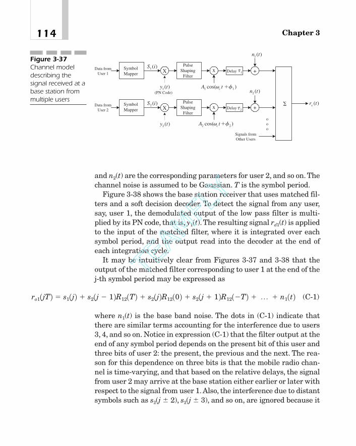
and n2(t) are the corresponding parameters for user 2, and so on. Thechannel noise is assumed to be Gaussian. T is the symbol period.
Figure 3-38 shows the base station receiver that uses matched fil-ters and a soft decision decoder. To detect the signal from any user,say, user 1, the demodulated output of the low pass filter is multi-plied by its PN code, that is, y1(t). The resulting signal rd1(t) is appliedto the input of the matched filter, where it is integrated over eachsymbol period, and the output read into the decoder at the end ofeach integration cycle.
It may be intuitively clear from Figures 3-37 and 3-38 that theoutput of the matched filter corresponding to user 1 at the end of thej-th symbol period may be expressed as
(C-1)
where n1(t) is the base band noise. The dots in (C-1) indicate thatthere are similar terms accounting for the interference due to users3, 4, and so on. Notice in expression (C-1) that the filter output at theend of any symbol period depends on the present bit of this user andthree bits of user 2: the present, the previous and the next. The rea-son for this dependence on three bits is that the mobile radio chan-nel is time-varying, and that based on the relative delays, the signalfrom user 2 may arrive at the base station either earlier or later withrespect to the signal from user 1.Also, the interference due to distantsymbols such as s2(j � 2), s2(j � 3), and so on, are ignored because it
ro11jT 2 � s11j 2 � s21j � 1 2R121T 2 � s21j 2R1210 2 � s21j � 1 2R121�T 2 � p � n11t 2
Chapter 3114
XSymbolMapper
xData fromUser 1
(PN Code)
PulseShaping
Filter
)cos( 11 � ��tA c
)(1 iS
)(1 ty
1 �Delay
)(1 tn
+
)(trx
XSymbolMapper xData from
User 2
PulseShaping
Filter
)cos( 22 � �� tA c
)(2 iS
)(2 ty
2 �Delay
)(2 tn
+
ooo
Signals fromOther Users
�
Figure 3-37Channel modeldescribing thesignal received at abase station frommultiple users
TEAMFLY
Team-Fly®
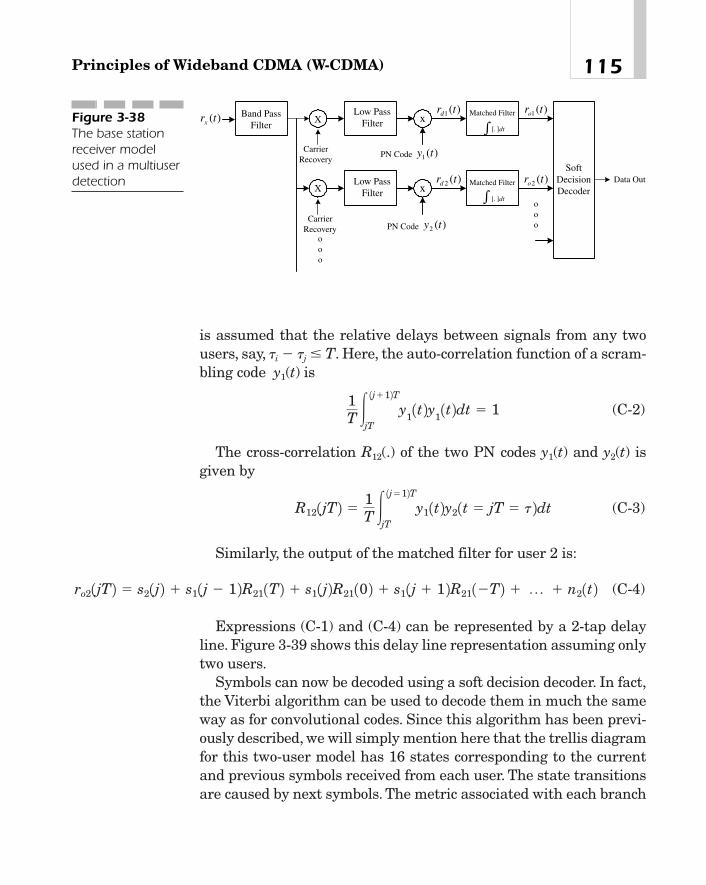
is assumed that the relative delays between signals from any twousers, say, �i � �j � T. Here, the auto-correlation function of a scram-bling code y1(t) is
(C-2)
The cross-correlation R12(.) of the two PN codes y1(t) and y2(t) isgiven by
(C-3)
Similarly, the output of the matched filter for user 2 is:
(C-4)
Expressions (C-1) and (C-4) can be represented by a 2-tap delayline. Figure 3-39 shows this delay line representation assuming onlytwo users.
Symbols can now be decoded using a soft decision decoder. In fact,the Viterbi algorithm can be used to decode them in much the sameway as for convolutional codes. Since this algorithm has been previ-ously described, we will simply mention here that the trellis diagramfor this two-user model has 16 states corresponding to the currentand previous symbols received from each user. The state transitionsare caused by next symbols. The metric associated with each branch
ro21jT 2 � s21j 2 � s11j � 1 2R211T 2 � s11j 2R2110 2 � s11j � 1 2R211�T 2 � p � n21t 2
R121jT 2 �1T �
1j�12TjT
y11t 2y21t � jT � t 2dt
1T �
1j�12TjT
y11t 2y
11t 2dt � 1
115Principles of Wideband CDMA (W-CDMA)
Band PassFilter
Matched Filter
SoftDecisionDecoder
XLow Pass
Filter x
CarrierRecovery
Data Out
)(1 ty
[. ]dt�
Matched FilterX
Low PassFilter x
CarrierRecovery )(2 ty
[. ]dt
)(trx
ooo
ooo
)(1 trd
)(2 trd
)(1 tro
)(2 tro
PN Code
PN Code
�
Figure 3-38The base stationreceiver modelused in a multiuserdetection

of the trellis is given by values of the cross-correlation functions.However, now, at each state, the survivor path is the one whose met-ric is closest to the output of the matched filter.
In UMTS, both long and short codes may be used on uplinks. How-ever, short codes are better from the standpoint of multiuser detec-tion because their cross-correlation remains constant over a numberof consecutive symbol periods. Because the number of states in thetrellis diagrams, and consequently the computational complexity,increase exponentially with the number of users, the procedure isnot very useful in practical applications.
References[1] A.J. Viterbi, “The Evolution of Digital Wireless Technology
from Space Exploration to Personal Communication Ser-
Chapter 3116
)1(2 js )(2 js
)(12 TR )0(12R )(12 TR
+
X X X
s j2
1( )
)1(1 js )(1 jTro
)1(1 js)(1 js
)(21 TR )0(21R )(21 TR
+
X X X
s j1
1( )
)(2 jTro)(2 js
Delay T Delay T
Delay TDelay T
+
−
+
+
−
−
−
Figure 3-39Two-user delay linemodel in multiuserdetection. Themaximum delay isassumed to be T,the symbol period.

vices,” IEEE Trans. Veh. Technol., Vol. 43, No. 3, pp. 638—644,August 1994.
[2] N. Abramson, “The Throughput of Packet BroadcastingChannels,” IEEE Trans. Comm., Vol. COM-25, No.1, pp. 117—128, January 1977.
[3] L. Kleinrock and F.A. Tobagi, “Packet Switching in RadioChannels: Part I—Carrier Sense Multiple Access Modes andTheir Throughput-Delay Characteristics,” IEEE Trans.Comm., Vol. COM-23, No.12, pp. 1400—1416, December 1975.
[4] L. Kleinrock and F.A. Tobagi, “Packet Switching in RadioChannels: Part II—The Hidden Terminal Problem in CarrierSense Multiple Access Modes and the Busy Tone Solution,”IEEE Trans. Comm., Vol. COM-23, No.12, pp. 1417—1433,December 1975.
[5] N.D. Wilson, et al., “Packet TDMA Versus Dynamic TDMA forMultiple Access in Integrated Voice/Data PCN,” IEEE JSAC,Vol. 11, No.6, pp. 870—83, August 1993.
[6] G.L. Turin, “Introduction to Spread Spectrum AntimultipathTechniques and Their Application to Urban Digital Radio,”Proc. IEEE, Vol. 68, No.3, pp. 328—353, March 1980.
[7] R.L. Pickholz, L.B. Milstein, and D. L. Schilling, “SpreadSpectrum for Mobile Communications,” IEEE Trans. Veh.Technol., Vol. 40, No.2, pp. 313—322, May 1991.
[8] A.J. Viterbi, “Convolutional Codes and Their Performance inCommunications Systems,” IEEE Trans. Comm. Tech., Vol.COM-19, No. 5, pp. 751—772, October 1971.
[9] J.A. Heller and I.M. Jacobs, “Viterbi Decoding for Satelliteand Space Communication,” IEEE Trans. Comm. Tech., Vol.COM-19, No. 5, pp. 835—848, October 1971.
[10] G.D. Forney, “The Viterbi Algorithm,” Proc. IEEE, pp. 268—278, March 1973.
[11] M.C. Jeruchim, P. Balaban, and K.S. Shanmugan, Simulationof Communication System. New York: Plenum Press, 1992.
[12] 3GPP TS 25.213: UMTS; Spreading and Modulation, 2000.
117Principles of Wideband CDMA (W-CDMA)
[13] R.W. Lucky, J. Salz, and E.J. Weldon, Principles of Data Com-munications. New York: McGraw-Hill, 1968.
[14] S.W. Golomb, Shift Register Sequences. Aegean Park Press,1982.
[15] S. Lin, An Introduction to Error-Correcting Codes. New Jer-sey: Prentice Hall, 1970.
[16] M.W. Oliphant, “Radio Interfaces Make the Difference in 3GCellular Systems,” IEEE spectrum, pp. 53—58, October 2000.
[17] G.J.R. Povey, et al., “A Decision-Directed Spread-SpectrumRAKE Receiver for Fast-Fading Mobile Channel,” IEEETrans. Veh. Technol., Vol. 43, No. 3, pp. 491—502, August 1994.
[18] J.S. Lehnert and M.B. Pursley, “Multipath Diversity Recep-tion of Spread-Spectrum Multiple-Access Communications,”IEEE Trans. Comm., Vol. COM-35, No. 11, pp. 1189—1198,November 1987.
[19] T. Ojanpera and R. Prasad (Ed.), Wideband CDMA for ThirdGeneration Mobile Communications. Boston: Artech House,1998.
[20] H. Holma and A. Toskala (Ed.), W-CDMA for UMTS. NewYork: John Wiley, 2000.
[21] S. Glisic and B. Vucetic, Spread Spectrum CDMA Systems forWireless Communications. Boston: Artech House, 1997.
[22] S. Verdu, “Minimum Probability of Error for AsynchronousGaussian Multiple-Access Channels,” IEEE Trans. Inform.Theory, Vol. IT-32, pp. 85—96, January 1986.
[23] S. Verdu and H.V. Poor, “Abstract Dynamic ProgrammingModels under Commutativity Conditions,” SIAM J. ControlOptimization, Vol. 24, pp. 990—1006, July 1987.
[24] R. Prasad, CDMA for Wireless Personal Communications.Boston: Artech House, 1996.
[25] R.H. Kohno, H. Imai, and M. Hatori, “Cancellation Tech-niques of Co-Channel Interference in Asynchronous SpreadSpectrum Multiple Access Systems,” Trans. IECE (Electron-ics and Communications in Japan), Vol. 66, pp. 416—423, May1983.
Chapter 3118

[26] R.H. Kohno, H. Imai, M. Hatori, and S. Pasupathi, “Combina-tion of an Adaptive Array Antenna and a Canceller of Inter-ference for Direct-Sequence Spread-Spectrum MultipleAccess Systems,” IEEE J. Selected Areas Comm., Vol. 8, No. 4,pp. 675—682, May 1990.
[27] Y.C. Yoon, R. Kohno, and H. Imai, “Spread-Spectrum MultipleAccess System with Co-Channel Interference Cancellationfor Multipath Fading Channels,” IEEE J. Selected AreasComm., Vol. 11, No. 7, pp. 1067—1075, May 1992.
[28] P. Patel and J. Holzman, “Analysis of Simple Successive Inter-ference Cancellation Scheme in DS/CDMA-System,” IEEE J.Selected Areas Comm., Vol. 12, No.5, pp. 796—807, June 1994.
[29] H. Imai, Essentials of Error-Control Coding Techniques. NewYork: Academic Press, 1990.
[30] N. Abramson, “Multiple Access in Wireless Digital AccessNetworks,” Proc. IEEE,Vol. 82, No. 9, pp. 1360—69, September1994.
[31] D.L. Schilling, “Wireless Communication Going into the 21stCentury,” IEEE Trans. Veh. Technol., Vol. 43, No. 3, pp. 645—652, August 1994.
[32] U. Grob, A.L. Welti, E. Zollinger, R. Kung, and H. Kaufman,“Micro-Cellular Direct-Sequence Spread Spectrum RadioSystem Using N-Path Rake Receiver,” IEEE J. Selected AreasComm., Vol. 9, pp. 772—780, June 1990.
[33] N.L.B. Chan, “Multipath Propagation Effects on a CDMACellular System,” IEEE Trans. Veh. Technol., Vol. 43, No. 4,pp. 848—855, November 1994.
[34] T.S. Rappaport, Wireless Communications. New Jersey: Pren-tice Hall, 1996.
[35] J.C. Liberti and T. S. Rappaport, Smart Antennas. New Jer-sey: Prentice Hall, 1998.
[36] R.T. Compton, Adaptive Antennas—Concepts and Perfor-mance. New Jersey: Prentice Hall, 1996.
[37] S.C. Swales, et al., “The Performance Enhancement of Multi-beam Adaptive Base Station Antennas for Cellular Land
119Principles of Wideband CDMA (W-CDMA)

Mobile Radio Systems,” IEEE Trans. Veh. Technol., Vol. VT-39, No. 1, pp. 56—67, February 1990.
[38] S. Anderson, et al., “An Adaptive Array for Mobile Communi-cations System,” IEEE Trans. Veh. Technol., Vol. VT-40, No. 1,pp. 230—236, February 1991.
[39] J.H. Winters, “Signal Acquisition and Tracking with AdaptiveArrays in the Digital Mobile Radio System IS-54 with FlatFading,” IEEE Trans. Veh. Technol., Vol. VT-42, No. 4, pp. 377—384, November 1993.
[40] J. Kennedy, et al., “Direction Finding and ‘Smart Antennas’Using Software Radio Architectures,” IEEE Commun. Mag.,Vol. 33, No.5, pp. 62—68, May 1995.
[41] G. Tsoulos, et al., “Wireless Personal Communications for the21st Century: European Technological Advances in AdaptiveAntennas,” IEEE Commun. Mag., Vol. 35, No. 9, pp. 102—109,September 1997.
[42] V.K. Garg, et al., “Application of Adaptive Array Antenna to aTDMA Cellular/PCS System,” IEEE Commun. Mag., Vol. 35,No. 10, pp. 148—152, October 1997.
[43] ETSI Draft EN 301 704 Version 7.1.0, Adaptive Multi-RateSpeech Transcoding, 1999.
[44] N.S. Jayant, “High-Quality Coding of Telephone Speech andWideband Audio,” IEEE Comm. Mag., Vol. 28, No. 1, pp. 10—19, January 1990.
[45] P. Vary, et al., “Speech Codec for the European Mobile RadioSystem,” Proc. ICASSP ‘88, pp.227—230, April 1988.
[46] J. Makhoul, “Linear Prediction: A Tutorial Review,” Proc.IEEE, Vol. 63, pp. 561—80, April 1975.
Chapter 3120

cdmaOne andcdma2000
CHAPTER 44
Copyright 2002 M.R. Karim and Lucent Technologies. Click Here for Terms of Use.
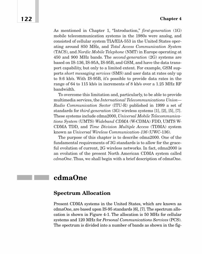
As mentioned in Chapter 1, “Introduction,” first-generation (1G)mobile telecommunication systems in the 1980s were analog, andconsisted of cellular system TIA/EIA-553 in the United States oper-ating around 850 MHz, and Total Access Communication System(TACS), and Nordic Mobile Telephone (NMT) in Europe operating at450 and 900 MHz bands. The second-generation (2G) systems arebased on IS-136, IS-95A, IS-95B, and GSM, and have the data trans-port capability, but only to a limited extent. For example, GSM sup-ports short messaging services (SMS) and user data at rates only upto 9.6 kb/s. With IS-95B, it’s possible to provide data rates in therange of 64 to 115 kb/s in increments of 8 kb/s over a 1.25 MHz RFbandwidth.
To overcome this limitation and, particularly, to be able to providemultimedia services, the International Telecommunications Union—Radio Communication Sector (ITU-R) published in 1999 a set ofstandards for third-generation (3G) wireless systems [1], [2], [5], [7].These systems include cdma2000, Universal Mobile Telecommunica-tions System (UMTS) Wideband CDMA (W-CDMA) FDD, UMTS W-CDMA TDD, and Time Division Multiple Access (TDMA) systemknown as Universal Wireless Communication-136 (UWC-136).
The purpose of this chapter is to describe cdma2000. One of thefundamental requirements of 3G standards is to allow for the grace-ful evolution of current, 2G wireless networks. In fact, cdma2000 isan evolution of the present North American CDMA system calledcdmaOne. Thus, we shall begin with a brief description of cdmaOne.
cdmaOne
Spectrum Allocation
Present CDMA systems in the United States, which are known ascdmaOne, are based upon IS-95 standards [6], [7].The spectrum allo-cation is shown in Figure 4-1. The allocation is 50 MHz for cellularsystems and 120 MHz for Personal Communications Services (PCS).The spectrum is divided into a number of bands as shown in the fig-
Chapter 4122
ure. Only those combinations of these bands that are considered asvalid by the FCC may be used by a service provider.
The available spectrum may be thought of as consisting of a num-ber of channels with a nominal spacing of 30 kHz for a cellular sys-tem and 50 kHz for a PCS. Thus, as an example, there are 1,200 FDDchannels in a PCS. Starting from a given channel, a CDMA carriermay include a number of these channels. However, for satisfactoryoperation, CDMA carriers should be separated by at least 25 chan-nels or 1.25 MHz for PCS. Thus, the nominal bandwidth of a CDMAsystem is 1.25 MHz.
Physical Channels
In the uplink, there are two physical channels—the access channeland traffic channel. A mobile station may use an access channel tosend signaling messages such as a call origination request, a pageresponse, a registration request, an order message, and so on. A sys-tem may have one or more access channels, each associated with apaging channel. A traffic channel carries user traffic, such as speechor data, and may also be used during a call to send signaling mes-sages, such as a handoff completion or a pilot strength measurementmessage, report power measurements to the base station, and so on.
In the downlink, there are four classes of physical channels—apilot channel, a sync channel, up to 7 paging channels, and up to 55traffic channels. In another possible configuration, the sync and pag-ing channels may be replaced by traffic channels.
123cdmaOne and cdma2000
824 825 835 845 846.5 849 869 870 880 890 891.5 894 MHz
(a)
1850 1865 1870 1885 1890 1895
MHz(b)
1930 1945 1950 1965 1970 19751910 1990
Base Stations MobilesBase StationsMobiles
A" A B A' B' B'A'A" A B
A AB BC CD DE EF F
Figure 4-1The spectrumallocation in IS-95:(a) Cellular (b) PCS

For each active forward CDMA channel, there is a pilot channelthat continuously sends a carrier modulated by an all-zero Walshcode so that mobile stations can synchronize to a base station. Thissignal can also be used as a reference in coherent demodulationand timing recovery at a mobile station. Similarly, a mobile stationcan measure the signal strength of a pilot channel, and report theresult to the serving base station so that it can decide if a handoffis necessary.
The sync channel transmits information that enables mobile sta-tions within the coverage area of a base station to acquire frame syn-chronization after achieving the pilot channel synchronization. Theinformation rate on the sync channel is 1,200 b/s. The channel rate,however, is 4.8 kb/s because the synchronization stream is encodedinto a convolutional code of rate 1/2 and then repeated once beforebeing interleaved. The sync channel superframe is 80 ms, while atraffic channel frame is 20 ms.
A paging channel carries system overhead information, such assystem parameters, access parameters, a CDMA channel list, aneighbor list, and so on, as well as messages directed to mobile sta-tions such as a general page message, alert, abbreviated alert,release, reorder, and so on. The information rate on a paging channelmay be either 9.6 kb/s or 4.8 kb/s. The incoming data is encoded intoa covolutional code of rate 1/2. Encoded symbols are repeated if thedata rate is 4.8 kb/s and interleaved before being spread by anorthogonal code.
The purpose of a forward traffic channel is to send the user dataas well as signaling messages to a mobile station during a call. Theinformation rate on this channel may be 8.6 kb/s, 4.0 kb/s, 2.0 kb/s,and 0.8 kb/s.
We will now describe the transmit functions of a cdmaOne syst-tem.
Reverse Channel Transmit Functions
A functional block diagram of transmit functions on a reverse trafficchannel is shown in Figure 4-2. User data streams, which may orig-inate at different rates, are arranged in 20 ms frames. If the data
Chapter 4124
TEAMFLY
Team-Fly®

rate is 8.6 or 4.0 kb/s, some frame-quality indicators are added to theincoming frames. To ensure proper operation of the channel encoder,all incoming frames are appended with some tail bits and thenpassed to a convolutional encoder of rate 1/3 and constraint length 9.Because we would like to have a constant rate at the input of theinterleaver regardless of the user data rates, the encoder output forlower data rates (4.0 kb/s and less) is repeated on a bit-by-bit basisin the symbol repetition block so that its output is 28.8 k/s. Thus, theoutput of the symbol repeater consists of two copies of the code sym-bols if the user data rate is 4 kb/s, four copies if the incoming datarate is 2.0 kb/s, and so on. This output is applied to a block inter-leaver of depth 20 ms so that any two adjacent bits at the input arespaced 1.1111 ms apart at the output.
The output of the interleaver is passed through an orthogonalmodulator, where each 6-bit code symbol is converted into a 64-bitmodulation symbol using a 64 � 64 Walsh matrix. The modulatoroutput feeds into a data burst randomizer that allows only one copyof the code symbols to be transmitted. To this end, each 20 ms frameof the interleaver output is divided into 16 blocks, or power controlgroups as they are called, as shown in Figure 4-3(a). The transmitteris then gated on during only some of these groups, depending upon
125cdmaOne and cdma2000
Add FrameQuality Ind. &
Tail Bits
ChannelEncoder
R = 1/3, K = 9
BlockInterleaver
SymbolMapper
Low PassFilter
+
+
+
x
x
900
A tccos
I-channel Seq.1.2288 Mc/s
Q-channel Seq.1.2288 Mc/s
User Info
8.6, 4.0, 2.0,0.8 kb/s
A
SymbolRepetition
9.6, 4.8, 2.4,1.2 kb/s
28.8, 14.4,7.2, 3.6 ks/s
28.8 ks/s
28.8 ks/s
64-aryOrthogonalModulation
307.2 kc/s
800 Hz
Data BurstRandomizer
Long CodeGenerator
Long CodeMask
1.2288Mc/s
SymbolMapper
Low PassFilter
I
Q Delay
Tc / 2
ωΣ
Figure 4-2Transmit functionsof an IS-95 reversechannel

the user data rate. For example, if the rate is 9.6 kb/s, the transmit-ter must be gated on all the time. If it is 4.8 kb/s, the transmittershould be activated only half the time, and so on. Figure 4-3(b) showsthe power control groups for a data rate of 4.8 kb/s. Notice that thefirst two groups marked 0 and 0 have identical data streams. Simi-larly, groups 1 and 1 are identical, and so on. Because only one-halfof the code symbols are to be transmitted, in a simple case, the trans-mitter could be gated on during each alternate group. Instead, thedata burst randomizer randomly selects the groups during which thetransmitter is gated on, making sure that a given symbol is trans-mitted exactly once. The random selection is indicated by the shadedgroups of Figure 4-3(b).
Referring again to Figure 4-2, the output of the data burst ran-domizer is spread by a long code, which is derived in the followingway. The output of a maximal length shift register sequence with acharacteristic polynomial of degree 42 is ANDed with a long codemask that is constructed with the permuted electronic serial number(ESN) of the mobile station. Thus, the long code mask and hence theoutput of the long code generator are unique for each user. Becausethe randomizer output is 307.2 kc/s and the chip rate is 1.2288 Mc/s,each bit is spread by a factor of 4.
The resulting output is divided into two sequences, the I and Qsequences, which are spread by a zero-offset, I and Q pilot pseudo-noise (PN) sequences of period 215 � 1 (chips). To minimize the out-of-band energy, the resulting outputs are passed through a low-pass
Chapter 4126
0 1 14 15o o o o (a)
(b)1 1
32
2 20 0 6 6 7 7
16 ms
1.25 ms
3 3 4 4 5 5
Figure 4-3Data burstrandomization

filter with a nominal bandwidth of about 740 kHz. The filtered out-puts are symbol-mapped and then modulate the carrier.
Notice that the Q-channel data, after spreading by the Q-channelpilot PN sequence, is delayed by Tc/2 before it is filtered, where Tc isthe chip period. This is known as offset QPSK (OQPSK) modulation.Because the I channel and Q channel are now delayed by thisamount, only one of them undergoes a phase transition at a time.Since, in this case, the maximum phase change that can take placeat any time is only �90 degrees, the envelope of the modulated sig-nal never goes through zero, and furthermore, varies much less thanfor QPSK. Consequently, the resulting signal is more suitable foramplification with nonlinear amplifiers.
The transmit functions of the reverse access channel are slightlydifferent. For example, there is only one data rate for this channel,namely, 4.4 kb/s. Thus, the code symbols are repeated just once. Nodata burst randomizer is used. Each access channel is spread by along code, which is derived in the same manner as for the reversetraffic channel except for a different long code mask that includesthe access channel number, the paging channel number, the base sta-tion identification number, and so on.
Forward Channel Functions
cdmaOne uses a system-wide reference time scale that is based upona global positioning system synchronized with a universal coordi-nated time. Each base station derives its time base from this refer-ence time scale. The functional block diagram of a base stationtransmitter is shown in Figure 4-4.
The pilot channel carries an all-zero pattern and is spread byWalsh function 0 (W0).
The sync channel is used to transmit a synchronizing sequence at1.2 kb/s. The data is encoded with a convolutional code of rate 1/2 andconstraint length 9. The output of the channel encoder is repeatedonce so that the resulting bit rate is 4.8 kb/s. It is passed through ablock interleaver and then spread out with Walsh function 32 (W32).
The paging channel data, which may operate at either 9.6 kb/s or4.8 kb/s, is encoded in a code of rate 1/2, symbol-repeated, interleaved,
127cdmaOne and cdma2000

scrambled, and spread by a Walsh function (W1—W7). The scram-bling code is derived by ANDing the output of a 42-bit maximal-length shift register sequence with a 42-bit mask that includes,among other things, a 3-bit paging channel number. The resultingoutput is passed through a decimator that is clocked at 19.2 kb/s.1
Chapter 4128
SymbolRepetition
ChannelEncoder
BlockInterleaver
Low PassFilter
+
+
+
x
x
900
A tccos
I-channel Pilot PNSequence
Q-channel Pilot PNSequence 1.2288
Mc/s
Paging Channel9.6, 4.8 kb/s
SymbolRepetition
ChannelEncoder
BlockInterleaver
19.2 kb/sWalsh Function p
1.2288 Mc/s
+
Walsh Function N1.2288 Mc/s
A
A
Sync Channel1.2 kb/s
SymbolRepetition
ChannelEncoder
BlockInterleaver
Walsh Function 321.2288 Mc/s
+ A2.4 kb/s
4.8 kb/s 4.8 kb/s
Walsh Function 01.2288 Mc/s
+Pilot Channel(All zeros)
A
Long CodeGenerator
Decimator
+Add Frame
Quality Ind. andEncoder Tail Bits
Long CodeGenerator
Decimator
+
Power Control 800 b/s
Puncturing
19.2 kb/s
Long Code Maskfor User m
Long Code Mask forGiven Paging Channel
19.2 kb/s
I
Q
SymbolMapper
SymbolMapper
Low PassFilter
Traffic fromUser m
8.6,4.0,2.0,0.8 kb/s
800 b/s
Decimator
oo
MUX
ωΣ
Figure 4-4Transmit functionson forwardchannels in IS-95
1Scramblers are generally used to provide encryption and security for the user infor-mation and also ensure that there are enough transitions in the channel sequence fortiming recovery at the receiver.

Data rates on a forward traffic channel may be 8.6, 4.0, 2.0, or 0.8kb/s. If it is 8.6 kb/s, 12 bits of frame quality indicators (that is, CyclicRedundancy Check [CRC]) are added to each 20 ms frame by encod-ing it into a block code using a generator polynomial of degree 12. Ifthe data rate is 4.0 kb/s, 8 bits of CRC are added to each frame byencoding it into a block code with a generator polynomial of degree8. For other data rates, no such CRCs are added.To reset the encoder,a sequence of all-zero tail bits is appended to each frame. The result-ing output is encoded, interleaved, repeated on a symbol-by-symbolbasis, and scrambled in the same way as a paging channel. However,in this case, the 42-bit long code mask is constructed with the 32-bitelectronic serial number of the particular user.
Once every 1.25 ms, a power control bit with a duration of 2 codesymbols is transmitted over a forward traffic channel to indicate tothe mobile station whether it should increase or decrease its trans-mitter power level.2 If this bit is a 0, the power level should beincreased. Otherwise, it is to be decreased. Actually, each power con-trol bit is inserted in the forward traffic channel by replacing, orpuncturing, as it is called, two adjacent code symbols, which areselected randomly for this purpose.
The I- and Q-channels are spread by two maximal-length pilot PNsequences of period 215 � 1 (chips) with an offset with respect to areference PN sequence.This offset, which is unique for each base sta-tion, is expressed in terms of the chip rate and is given by 64n chipswhere 0 � n � 511. Thus, cdmaOne is a synchronous system whereeach base station is uniquely identified by the offset index n.
It is worth mentioning here that each forward channel type—pilot, paging, sync, and traffic channels—is separated at a mobilestation by means of the Walsh codes. All long codes are the same.However, each paging or forward traffic channel is associated with aunique long code mask. Thus, mobile stations can separate trafficchannels by despreading the received signal with a Walsh code (W8—W31, W33—W63) and the user-specific long code.
129cdmaOne and cdma2000
2The symbol rate of the interleaver output on a traffic channel is 19,200 symbols/s.Thus, there are 384 code symbols in a 20 ms frame or 24 symbols in each 1.25 msinterval. Each of these intervals is called a power control group.

Power Control
Reasons for Power Control One of the most important require-ments in a CDMA system is the capability of the user equipment(UE) and base transceiver stations to control their transmitterpower output. In fact, without this capability, the system will notwork effectively and attain its full capacity. To understand the rea-son, consider the so-called far-near problem in a cellular system illus-trated in Figure 4-5, where a base station is receiving signalssimultaneously from two mobile stations, one close to the base sta-tion and the other farther from it near the edge of a cell. BecauseUE1 is closer than UE2, if both mobile stations are transmitting atthe same level, the signal from UE1 will be generally stronger thanthe signal from UE2. Because all stations in a CDMA cell operate onthe same carrier but use only different PN codes, and because thereceived SIR for UE2 is lower, the detection of this signal at the basestation is subject to a higher bit error rate.3 In fact, depending upon
Chapter 4130
3Notice that in a CDMA system, the interfering signal for UE1 is the transmitted sig-nal from UE2 as well as all other stations. Similarly, the interference to UE2 is causedby the transmitted signal from UE1 and all other mobiles.
d1
d2
UE1
UE2
BTS
Figure 4-5The far-nearproblem in acellular system

relative distances d1 and d2, the stronger signal may swamp out theweaker signal. Furthermore, because the two signals fade indepen-dently, it is possible that the instantaneous value of the signal fromUE1 is above its average level while at the same time the signal fromUE2 is substantially below its mean, thus making it more difficultfor the base station to detect the weaker signal.
To overcome this problem, the base station measures the signalfrom a mobile station, and if it is above a threshold, it sends a com-mand to that station to reduce its power level so that the signal thatthe base station receives from that mobile station is equal to signalsfrom other mobile stations. Similarly, if the signal is below a thresh-old, the user equipment may be asked to increase its transmitterpower. However, in this case, there is a possibility of an increasedinterference to neighboring cells particularly if the mobile station isnear the edge of its cell. The power control commands are sent at 800b/s by puncturing code symbols on a traffic channel once every 1.25ms (or 16 times per 20 ms frame).
The transmit power control commands can also be used to coun-teract the effect of fades. Consider, for example, the fading signal ofFigure 4-6. The signal is above the local mean during T1, T2, and T3
but below that average at all other times. The bases station can
131cdmaOne and cdma2000
Received Signal Envelope
t
AverageSignal
Leve
1T 2T3T
Figure 4-6A fading signal

remove these variations and receive the signal at a fairly constantlevel by repeatedly sending transmit power control commands sothat the UE reduces the power level during T1, T2, and T3 andincreases it at all other times.
Another side benefit of the power control is that mobile stationsmay now be able to operate at an optimum power level. Thus, CDMAhandsets may have a more compact design and longer battery life. Itwould also result in improved speech quality, particularly in urbanand dense urban areas.
Uplink and Downlink Power Control An effective power con-trol is a fundamental requirement for maximizing the capacity of aCDMA system. As we shall see later, the system capacity (that is,the maximum number of mobile stations that can be served in aCDMA system) is maximum when the transmitter power of eachmobile station is adjusted such that the received SIR from eachmobile is just about enough to maintain the desired quality.
Power control is applied on an uplink (that is, reverse) channel sothat the base station receives a satisfactory SIR from each mobilestation. To this end, the base station may measure the received sig-nal strength, and if it is outside the limits of satisfactory operation,it orders the mobile station to adjust its transmit power accordingly.This is called a closed loop power control because it is based upondirect measurements of the desired signal. Alternatively, we couldcontrol the transmitter power on an uplink channel by measuring adifferent parameter that only gives an indirect indication of thetransmitter power. For example, the mobile station could measurethe signal received from the base station, estimate the path loss onthe forward channel, and accordingly adjust the transmit power ofthe reverse channel. Clearly, this adjustment works only if the pathloss variations on the forward and reverse channels are correlated.This is known as open loop power control.Thus, we can use both openand closed loop controls on a reverse channel.
Power control is also used on a downlink channel so that eachmobile station receives a satisfactory signal level from the base sta-tion. In this case, the algorithms are usually closed loop where eachmobile station measures the received signal on the forward channel
Chapter 4132

and, based upon the measurements, requests the base station toadjust its transmit power.
Handoff in IS-95
As we have indicated elsewhere, when a mobile station moves fromthe serving area of one base station to the serving area of a second,it should eventually communicate with the second base stationbecause the signal received form this station is stronger.This processof switching communication from one base station to another iscalled a handoff.
There are many different types of handoffs in cellular systems.Consider, for example, an analog Advanced Mobile Phone System(AMPS) system or a TDMA system such as IS-136 or GSM. In thesesystems, each adjacent cell in a cluster is assigned a different set offrequencies. Consequently, if a mobile station moves into an adjacentcell, its transmitter and receiver must begin to operate at newfrequencies. This is called a hard handoff. In this case, the mobilestation must terminate communication with the old base stationbefore starting communication with the new, thereby causing amomentary interruption of the voice or data signal. Similarly,because each sector of a cell in these systems is assigned a differentchannel set, a hard handover takes place when a mobile stationmoves from one sector to another.
Things are different in a CDMA system. If two adjacent CDMAsystems use two different carrier frequencies, clearly, there will be ahard handoff when a mobile station travels from one system toanother. If, however, two adjacent base stations operate on the sameCDMA carrier, it may be possible for the mobile station to use trafficchannels associated with both base stations at the same time andprovide diversity by combining its forward traffic channels, thusreducing the possibility of signal disruptions. In this case, we saythat the mobile is in a soft handoff.
Even though the mobile is in communication with both stations,only one of them, called the primary base station, is responsible forcall controls. The other base station is termed a secondary base
133cdmaOne and cdma2000
station. If, at some later time, the signal received from one base sta-tion is significantly stronger than the signal from the other base sta-tion, the weaker base station may eventually drop out. For example,if based on the pilot strength measurement by the mobile station,the primary base station determines that the secondary base stationis weaker, it may request the mobile switching center to drop the sec-ondary base station from the soft handoff. If the primary base stationitself is weaker, it indicates to the mobile station that it is going todrop itself from the soft handoff and then transfer control to the tar-get base station. Clearly, a three-way handoff is also possible becausemobile stations may be receiving signals with comparable SIRs fromthree adjoining base stations.
An intracell or intersector handoff is called a softer handoff. In thiscase, if a mobile communicates with two sectors of the same cell, theassociated base station can generate an optimum output using arake receiver.
Handoffs Supported in IS-95 IS-95 supports three types ofhandoffs:
� Soft and softer handoff In this case, all forward trafficchannels used by a mobile station operate at the samefrequency.
� Hard handoff This takes place when the participating basestations use two different CDMA carrier frequencies.
� CDMA to analog cellular system handoff This handoff isinvoked when a mobile station moves from a CDMA serving areato an adjacent analog system.
Soft Handoff Procedure Recall that in CDMA the pilot channeltransmits a continuous,Walsh function W0-modulated carrier, whichprovides a reference phase that is required for coherent detectionand timing recovery at the receiver. Each pilot is identified by aunique offset of the two pilot PN sequences that are used to spreadthe forward and reverse CDMA channels. Mobile stations monitorthe pilots, which have the same CDMA frequency assignment, anduse their relative signal strength as a basis for handoff.
Chapter 4134
TEAMFLY
Team-Fly®
The idea behind soft handoffs is rather simple. Each mobile sta-tion searches for sufficiently strong pilots that are not associatedwith any of the forward traffic channels assigned to the particularmobile. If it finds one, it sends the signal strength measurement ofthat channel to the base station, which can then proceed to assign tothis mobile a forward traffic channel associated with that pilot. Inthis case, the handoff is said to be initiated by the mobile station.Because a base station is capable of measuring signal strengths, itcan also trigger a handoff if necessary.
For the purpose of handoff, a mobile station maintains four sets ofpilots:
� Active set It includes all pilots that are associated with thetraffic channels currently being used by this mobile station.
� Candidate set It consists of all pilots that are not in the activeset but which have been determined by the mobile as sufficientlystrong that their associated forward traffic channels can be usedby this mobile.
� Neighbor set These are pilots that are not included in the pre-vious two sets but are associated with all other base stations in theserving area and thus may be probable candidates for a handoff.
� Remaining set Pilots outside of the previous three sets formthe remaining set.
The handoff procedure is briefly the following. Refer to Figure 4-7.Base stations specify the size of a search window during which amobile station should search the pilots. When the signal strength ofa pilot in the neighbor set exceeds the pilot detection thresholdlabeled T_ADD, the mobile station sends the measurement informa-tion to the primary base station and moves that pilot to the candi-date set.4 This is shown as time t1 in the figure.
On receiving the measurement, the base station transmits at t2 aHandoff Direction message to the mobile station indicating that thispilot should be an active pilot, and also sends a soft handoff request
135cdmaOne and cdma2000
4The signal strength measured is actually Ec/I0 where Ec is the received pilot energyper chip and I0 is the total received spectral density due to signal and noise.
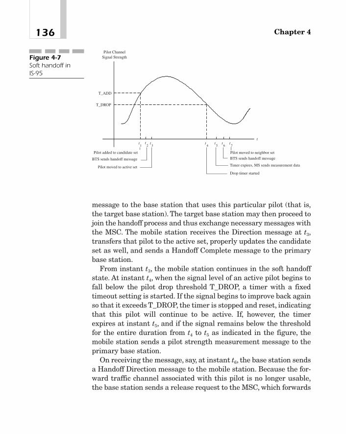
message to the base station that uses this particular pilot (that is,the target base station). The target base station may then proceed tojoin the handoff process and thus exchange necessary messages withthe MSC. The mobile station receives the Direction message at t3,transfers that pilot to the active set, properly updates the candidateset as well, and sends a Handoff Complete message to the primarybase station.
From instant t3, the mobile station continues in the soft handoffstate. At instant t4, when the signal level of an active pilot begins tofall below the pilot drop threshold T_DROP, a timer with a fixedtimeout setting is started. If the signal begins to improve back againso that it exceeds T_DROP, the timer is stopped and reset, indicatingthat this pilot will continue to be active. If, however, the timerexpires at instant t5, and if the signal remains below the thresholdfor the entire duration from t4 to t5 as indicated in the figure, themobile station sends a pilot strength measurement message to theprimary base station.
On receiving the message, say, at instant t6, the base station sendsa Handoff Direction message to the mobile station. Because the for-ward traffic channel associated with this pilot is no longer usable,the base station sends a release request to the MSC, which forwards
Chapter 4136
T_ADD
t
T_DROP
3t
1t
2t
4t
5t
6t
7t
Pilot ChannelSignal Strength
Pilot added to candidate set
BTS sends handoff message
Pilot moved to active set
Drop timer started
Timer expires, MS sends measurement data
BTS sends handoff message
Pilot moved to neighbor set
Figure 4-7Soft handoff in IS-95

it to the target base station as part of the process to drop it from thesoft handoff.
The mobile station receives the Handoff Direction message attime t7, removes the pilot from the active set, adds it to the neighborset, and sends a Handoff Complete message to the base station.
CDMA allows for an idle handoff as well. If a mobile station, whilein the idle state, detects a pilot channel from another base station tobe significantly stronger than the pilot channel of the current basestation, it may decide to initiate a handoff.
cdma2000
System Features
Traffic Types Broadly speaking, cdma2000, like all other 3G tech-nologies, is expected to support the following types of traffic. Thedata rates may vary from 9.6 kb/s to 2 Mb/s:
� Traditional voice and voice over IP (VoIP)
� Data services� Packet data These services are IP-based with the
Transmission Control Protocol (TCP) or User DatagramProtocol (UDP) at the transport layer. Included in this categoryare the Internet applications, H.323-type multimedia services,and so on.
� Circuit-emulated broadband data Examples of this kind oftraffic include fax, asynchronous dial-up access, H.321-basedmultimedia services where audio, video, data, and control andindication are transmitted using circuit emulation overAsynchronous Transfer Mode (ATM), and so on.
� SMS
In addition, there are, of course, signaling services.3G systems are intended for indoor and outdoor environments,
pedestrian or vehicular applications, and fixed environments such as
137cdmaOne and cdma2000

wireless local loops. Cells sizes may range from a few tens of meters(say, less than 50 m for picocells) to a few tens of kilometers (inexcess of 35 km for large cells).
Bandwidth A cdma2000 system may operate at different band-widths with one or more carriers. In a multicarrier system, adjacentcarriers should be separated by at least 1.25 MHz as shown in Fig-ure 4-8(a). In an actual multicarrier system, each individual carrierusually has a bandwidth of 1.25 MHz and is separated from an IS-95 carrier by means of orthogonal codes. However, when three car-riers are being used in a multicarrier system, the bandwidthrequired is 5 MHz. To provide high-speed data services of the typediscussed previously, a single channel may have a nominal band-width of 5 MHz as indicated in Figure 4-8(b) with a chip rate of3.6864 Mc/s (that is, 3 � 1.2288 Mc/s).5 The bandwidth BW in Fig-ure 4-8(b), outside of which the power density is negligible, depends
Chapter 4138
BW
5 MHz
G G
1.25 MHz1.25 MHz
f
(a)
(b)
5 MHz
1 2 3Figure 4-8Bandwidthrequirements incdma2000
5Or, if necessary, the bandwidth of a single channel may be some multiple of 5 MHz.

on the pulse-shaping filter at the baseband.6 If a raised cosine filteris used, BW � Rc(1 � a), where Rc is the chip rate and a is the roll-off factor. If a � 0.25, BW � 4.6 MHz, and so the guard band G �
200 kHz. Clearly, an advantage of a wider bandwidth lies in the factthat it provides more resolvable paths that can be used in a multi-path diversity receiver to improve the system performance.
Quality of Service (QoS) At any time, multiple applications mayrun on a mobile station. A user may request a desired QoS depend-ing on the application, and the network is expected to guarantee therequested quality without any (noticeable) degradation in the QoScontracted by other active users.
Packet Mode Data Services cdma2000 supports packet modedata services [1]. Starting from an initial state, if there is a packetto send, the user attempts to establish the dedicated and commoncontrol channels using the multiple-access slotted Aloha scheme.7 In
139cdmaOne and cdma2000
6Recall that the purpose of this filter is to reduce out-of-band energy at the RF stageand minimize the intersymbol interference.7The Aloha system is a wireless computer communication network that was devel-oped in the late 1960s at the University of Hawaii. In this system, multiple user ter-minals could access a central computer over a radio link using a random accessscheme, whereby any terminal could seize the channel at any time and transmit apacket of a fixed length. If there was no contention from other terminals, the centralcomputer would receive the packet error-free, and send an acknowledgment. If auser terminal did not receive the acknowledgment, it would wait for a randomperiod of time, and retransmit the packet.A terminal would repeat this process untilit was successful or until it had attempted three times. The radio link operated inthe FDD mode, where the two frequencies used were 413.350 MHz and 413.475MHz. The bandwidth in either direction was 100 kHz. The data rate was 24,000bauds.
Since this access is purely random, transmissions form two or more terminals maycompletely or partially overlap, thereby significantly reducing the throughput. In theslotted Aloha scheme, where synchronized time slots are used for transmission pur-poses, a user can transmit only at the beginning of a slot. Thus, in case of contention,transmissions from multiple users would completely overlap. This approach, there-fore, improves the throughput considerably. For a detailed description, see N.Abram-son, “The Throughput of Packet Broadcasting Channels,” IEEE Trans. Commun., Vol.COM-25, No. 1, pp. 117–128, Jan. 1977.

this scheme, a reference clock is used to create a sequence of timeslots of equal duration. When a user has a packet to send, it canbegin to transmit, but only at the beginning of a time slot ratherthan at any arbitrary instant of time. Notice that although users aresynchronized via the reference clock, there is some probability thattwo or more users could begin to transmit at the same time.
When these channels are established, the user may send thepacket(s) over the dedicated control channel, and may also request atraffic channel of a desired bandwidth. Once this traffic channel hasbeen assigned, the user transmits the packet(s), maintaining syn-chronization and power control as necessary, and releasing the traf-fic channel either immediately following transmission or after afixed time-out period. If there are no more packets to send, the dedi-cated control channel is also released after a while, but the networkand link layer connections are maintained for a certain length oftime so that newly arrived packets, if any, may be sent without anychannel setup delays. At the end of that time period, short, infre-quent data packets may be sent over a common control channel. Theuser may either disconnect at this point, continue in this state indef-initely, or reestablish the dedicated control and traffice channels ifthere are large or frequents packets to send.
Transmit Diversity One of the advantages of W-CDMA is thepossibility of transmit diversity. This may be accomplished in twoways. First, with a 5 MHz, direct-spread CDMA system, the userdata may be divided into two or more streams, each spread with anorthogonal code, and then transmitted to mobile stations. Becauseof multipath diversity, the forward channel performance mayimprove significantly. Second, if it is a multicarrier system, user datastreams may be transmitted over different carriers on differentantennas (see Figure 3-5).
The Protocol Stack
cdma2000 takes the information—user data and signaling—fromthe higher layers and adds two lower-layer protocols before trans-
Chapter 4140
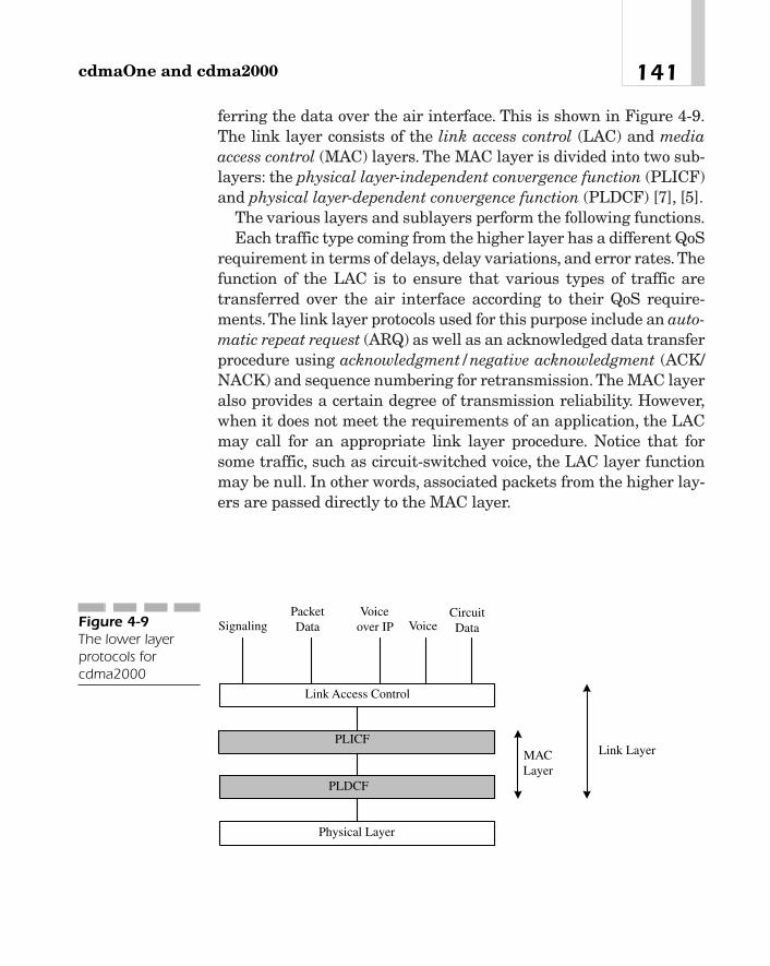
ferring the data over the air interface. This is shown in Figure 4-9.The link layer consists of the link access control (LAC) and mediaaccess control (MAC) layers. The MAC layer is divided into two sub-layers: the physical layer-independent convergence function (PLICF)and physical layer-dependent convergence function (PLDCF) [7], [5].
The various layers and sublayers perform the following functions.Each traffic type coming from the higher layer has a different QoS
requirement in terms of delays, delay variations, and error rates.Thefunction of the LAC is to ensure that various types of traffic aretransferred over the air interface according to their QoS require-ments.The link layer protocols used for this purpose include an auto-matic repeat request (ARQ) as well as an acknowledged data transferprocedure using acknowledgment/negative acknowledgment (ACK/NACK) and sequence numbering for retransmission. The MAC layeralso provides a certain degree of transmission reliability. However,when it does not meet the requirements of an application, the LACmay call for an appropriate link layer procedure. Notice that forsome traffic, such as circuit-switched voice, the LAC layer functionmay be null. In other words, associated packets from the higher lay-ers are passed directly to the MAC layer.
141cdmaOne and cdma2000
PacketData
Voiceover IP Voice
CircuitDataSignaling
Link Access Control
PLICF
PLDCF
Physical Layer
MACLayer
Link Layer
Figure 4-9The lower layerprotocols forcdma2000

A MAC sublayer performs the following functions:
� It controls user access to the physical layer (that is, themedium) by resolving, if necessary, contention among multipleapplications from the same user or among multiple users, andscheduling its resources so as to ensure efficient utilization ofbandwidth. Resources include buffers, spreading codes,convolutional encoders, and so on.
� User data and signaling information from the upper layers (thatis, the LAC layer and the higher layers) are multiplexed,mapped into different physical channels, and delivered to thephysical layer on a best-effort basis, providing a basic level oftransmission reliability.8
The MAC layer is divided into two sublayers:
� Functions that are independent of the physical layer, such ascontrolling access to the medium so as transmit packets, areperformed by the sublayer called PLICF. The user data andcontrol information are passed to the lower sublayer over a setof logical channels, such as a dedicated traffic channel, commontraffic channel, dedicated signaling channel, common signalingchannel, dedicated MAC channel carrying MAC messages,forward common MAC channel, and reverse common MACchannel.
� The second sublayer is the PLDCF. Functions performed at thissublayer when transmitting over the air interface includemultiplexing logical channels coming from PLICF, mappingthem into physical channels, assigning proper priorities to eachaccording to its QoS requirement, and delivering them to thephysical layer. The best-effort delivery of data services isperformed at this layer using a radio link protocol (RLP) forstreaming-mode user data, and a radio burst protocol (RBP) for
Chapter 4142
8In the best-effort service, the user specifies the maximum and minimum data rates.The amount of bandwidth allocated to a user may vary during the life of a call depend-ing on the congestion experienced by the network.

short bursts of user data over a common traffic channel. TheRLP uses an ARQ-based retransmission scheme. Thecorresponding protocols for handling signaling information arethe signaling radio link protocol (SRLP) and signaling radioburst protocol (SRBP).
Physical Channels
Forward Physical Channels As in IS-95, the pilot channel con-tinuously transmits a carrier modulated with an all-zero patttern sothat mobile stations can achieve initial cell synchronization. Amobile station may use the received signal as a reference carrier forcoherent demodulation, or measure the received signal strength andreport the measurement to a base station for handoff purposes.
A common auxiliary pilot channel has been added to cdma2000 sothat adaptive antennas can be used for beamforming to extend cov-erage, increase capacity, and provide higher data rates, among otherthings. Because beamforming is accomplished by combining signalsfrom different locations in the antenna’s aperture in an optimalmanner using an adaptation algorithm that requires as accurate achannel estimate as possible, it is necessary that the pilot and datasignals travel along the same path to the receiver [3], [4].
A dedicated auxiliary pilot channel is dedicated to a given mobilestation (or a group of mobile stations) for the purpose of beam steer-ing using an adaptive antenna array.
A sync channel operates at 1200 b/s, transmitting synchronizationmessages so that mobile stations in the coverage area of a base sta-tion can acquire frame synchronization after cell acquisition. For asingle carrier system with a channel bandwidth of 1.25 MHz, thechannel encoder used is of rate 1/2. If the system consists of multiplecarriers or a single carrier with a bandwidth of 5 MHz or more, theconvolution code used is of rate 1/3.
The paging channel is used to transmit paging and overhead mes-sages directed to mobile stations in the coverage area of a basestation. There are two data rates: 9.6 and 4.8 kb/s. For a singlecarrier system with a channel bandwidth of 1.25 MHz, the convolu-tional encoder used is of rate 1/2. If the system consists of multiple
143cdmaOne and cdma2000

carriers, or a single carrier with a bandwidth of 5 MHz or more, theencoder used is of rate 1/3.
The quick paging channel has been added so that a base stationcan send a quick paging message to a mobile station operating in theslotted mode. This message actually consists of a single bit, which isfollowed by a regular paging message in the slot that has been allo-cated to the particular mobile.
Next is the broadcast common channel. Instead of combining over-head and paging messages on a paging channel, the system perfor-mance can be improved to some extent by separating overheadmessages and sending them over this channel.
The common control channel is used to send layer 3 and MAClayer messages to mobile stations at 9.6 kb/s using frame sizes of 5,10 or 20 ms.
The dedicated control channel is similar to the common controlchannel, but uses frames that are 5 or 20 ms long.
The fundamental channel is used for lower data rates: 9.6 kb/sand its subrates, grouped as rate set 1, and 14.4 kb/s and its sub-rates, grouped as rate set 2.9 This channel is supported in bothsingle-carrier and multicarrier cdma2000 systems. Both 20 ms and5 ms frames are permissible.
Supplementary channel 1 and 2 are designed for higher datarates. Rates supported are shown in Table 4-1. Frames are usually20 ms long.
Reverse Physical Channels The reverse pilot channel is similarin concept to the forward pilot channel. Used in conjunction withreverse dedicated channels, it enables a base station to acquire ini-tial time synchronization and recover a phase-coherent carrier forcoherent demodulation in a rake receiver. It also includes a powercontrol subchannel, which sends one bit in each 1.25 ms power con-trol group or 16 bits in each 20 ms frame. The base station can usethis bit to adjust its power level when necessary.
Chapter 4144
9This is after adding the frame quality indicator bits to incoming frames.
TEAMFLY
Team-Fly®

The access channel transmits layer 3 and MAC layer messagesfrom different mobile stations to a base station. Multiple usersaccess this channel using a mechanism that is very similar to theslotted Aloha scheme. The data rate supported is 9.6 kb/s. There maybe more than one access channel, each identified by a unique orthog-onal code.
The common control channel, like the reverse access channel justdescribed, also carries layer 3 and MAC messages, and is accessed bymobile stations using the same multiple access scheme. Data ratessupported include 9.6, 19.2, and 38.4 kb/s.
The dedicated control channel, like the reverse fundamental orsupplementary channels, carries user data packets at 9.6 kb/s or14.4 kb/s in 5 ms or 20 ms frames.
The fundamental channel is similar to the forward fundamentalchannel. It supports a data rate of 9.6 kb/s and its subrates (4.8,2.7, and 1.5 kb/s), or 14.4 kb/s and its subrates (7.2, 3.6, and 1.8kb/s). For these rates, convolutional codes are used. A frame is usu-ally 20 ms long. However, in some cases, a 5 ms frame may also beused. Note that only a fundamental channel supports a 5 msframe.
Supplementary channel 1 and 2, which are similar to the forwardsupplementary channels, provide higher data rates: (1) 9.6, 19.2,
145cdmaOne and cdma2000
Rate Set 1 Rate Set 2
Single-carrier cdma2000 M � 9.6 kb/s, M � 1, 2, M � 14.4 kb/s, M � 1, 2,with a bandwidth of 4, 8, 16, and 32. Uses 4, 8, and 16. Uses 1.25 MHz channel encoder of channel encoder of
rate 1/2. rate 1/2.
Multicarrier cdma2000 M � 9.6 kb/s, M � 1, 2, M � 14.4 kb/s, M � 1, 2,where each channel has 4, 8, 16, 32, and 64. 4, 8, 16, 32, and 64.a bandwidth of 1.25 Uses channel encoder Uses channel encoder MHz, or a single-carrier of rate 1/3. of rate 1/4.system with a bandwidth of 5 MHz or multiples thereof
Table 4-1
Data ratessupported on asupplementarychannel incdma2000

38.4, 76.8, and 153.6 kb/s, and (2) 14.4, 28.8, 57.6, 115.2, and 230.4kb/s. Only 20 ms frames are supported. For these data rates, turbocoding may be used.
Forward Channel Transmit Functions
As an aid to understand the technology used in the implementa-tion of physical layer functions of a typical W-CDMA system, a sim-plified block diagram of the transmit functions of a multicarriercdma2000 base transceiver station was presented in Chapter 3,“Principles of Wideband CDMA,” (see Figure 3-5 of that chapter).Figure 4-10 shows a similar diagram of the transmit functions ofthe forward channels of a direct-spread, single-carrier cdma2000system. For simplicity, only a subset of the forward physical chan-nels is included in this figure. Notice the similarity betweencdma2000 and IS-95 (refer to Figure 4-4) forward channel transmitfunctions. Some of the differences are as follows.
cdma2000 has two traffic channel types—the fundamental andsecondary. A number of data rates are supported. Depending uponthe data rate, convolutional codes of rate 1/2, 3/8, 1/3, or 1/4 may be used.Both 10 ms and 5 ms frames are supported.
I- and Q-channel symbols are multiplied by gain factors to provide some additional power control. As in IS-95, cells areseparated by different pilot PN sequence offsets.10 However, now,complex spreading is used by, first, adding the real-valued I and Qsequences in quadrature (so that the result is a complex number)and then multiplying it with a another complex number SI � jSQ,where SI and SQ are, respectively, the I-channel and Q-channel pilotPN sequences. The output of this multiplication is a complex quan-tity whose in-phase and quadrature components are as shown in thelower part of the figure. With complex spreading, the output of thewave-shaping filter goes through zero only with low probability, thusleading to improved power efficiency.
Chapter 4146
10The period of these sequences is 215 � 1 chips.

Reverse Channel Transmit Functions
The functional block diagram of direct-spread, reverse-channeltransmit functions in cdma2000 is shown in Figure 4-11. Consider,first, the fundamental channel. The incoming data on this channel isprocessed in the usual way. Depending on the user data rate, a vari-able number of frame-quality indicator bits in the form of CRC areadded to a frame. A few tail bits are appended to ensure proper oper-ation of the channel encoder, which may be either a convolutional
147cdmaOne and cdma2000
W0
X X
X X
carrierW
Q
ComplexSpreading
Code
Walsh Code forPaging Channel
BlockInterleaver
PagingChannel
Wave-ShapingFilter
X
X
tA cos
Output
SymbolMapper
IS QSI Q
QS ISI Q
k = 9r = 1/2
SymbolRepettion
Paging ChannelLong Code Mask
Long CodeGenerator Decimator
+
oo
MUX P/S
I
Q
ChannelGain
ChannelGain
X
X
j
I QI jSS
+Pilot Channel
ConvolutionalEncoder
BlockInterleaver
SyncChannel
k = 9r = 1/2
SymbolRepettion +
Walsh Code forSync Channel
+
BlockInterleaver
Fundamental orSecondaryChannel
Conv.Encoder
SymbolRepettion
Long Code Mask
Long CodeGenerator
Decimator
+Add CRC
andEncoderTail Bits
A
B
C
D
A
D
Decimator
PC BitsMUX
carrierW
Wave-ShapingFilter
tA sin�
ω
∑
∑ ∑
−
+
+
Figure 4-10The functionalblock diagram ofdirect-spread(single-carrier)forward channeltransmit functionsin cdma2000

coder or a turbo coder. Code symbols are repeated, but dependingupon the rates, some of them are also deleted. The output of theinterleaver is spread with a Walsh code, mapped into modulationsymbols, and multiplied by gain factors, resulting in a signal labeledAfund.
The supplementary channels 1 and 2 and control channels areprocessed in the same way, although details might vary in somecases. For example, symbol puncturing is not done on a reverse ded-icated control channel. Similarly, the reverse pilot channel, whichconsists of a string of zeros (that is, real values of �1), is treated dif-ferently because it is not encoded into a channel code, interleaved ina block interleaver, or multiplied by a Walsh code. However, a powercontrol bit is inserted into the pilot channel for each power controlgroup or 16 power control bits per frame. For simplicity, we haveomitted these repetitions and merely indicated the processed out-puts of these channels as Asub1, Asub2, Acont, and Apilot.
The fundamental channel and supplementary channel 1 aresummed together giving an output Q. Similarly, the remaining chan-nels are summed separately, giving I as the output. Notice that inthis case, the I- and Q-channel sequences formed for QPSK modula-tion are independent of each other because they are derived from dif-ferent channels and not by splitting the data stream of a given
Chapter 4148
Wave-ShapingFilter
X
X
tAcos�
IS QSI Q�
QS ISI Q�IS
ReverseFundamental
Channel
Conv. orTurbo
Encoder
User mLong Code
Mask
+Add CRC
andEncoderTail Bits
Wave-ShapingFilter
tAsin�
SymbolMapper
WalshCode
Gain
SymbolRepettion &Puncture if
Needed
Interleaver fundA
1supA
2supA
contA
pilotA I
Q
ComplexSpreading
I
Q
I-ChannelPN Sequence
Q-ChannelPN Sequence
Walsh Code
QS
Complex CodeGenerator
�
�
�
Figure 4-11The functionalblock diagram ofdirect-spreadreverse channeltransmit functionsin cdma2000

channel into two sub-streams. The I and Q sequences are spread bya complex code of the type SI � jSQ, where SI and SQ are user-specificbecause they are obtained from a 42-bit long code mask for the givenuser, I- and Q-channel pilot PN sequences, and a Walsh code.
SummaryIn this chapter, we have described the fundamental aspects ofcdma2000, which is one of the systems specified by IMT-2000.Because cdma2000 is an evolved version of the current CDMA sys-tem known as cdmaOne, a brief description of this system is alsoincluded.The basic features and service capabilities of cdma2000 arediscussed. To provide services in cdma2000, a new link layer proto-col has been defined that consists of a LAC layer and a MAC layer.The functions performed by the different sublayers are brieflydescribed. This is followed by a description of the physical layer interms of the physical channels and the forward and reverse channeltransmit functions.
The distinctive features of a cdma2000 system may be summa-rized as follows:
� Wider bandwidth and higher chip rate For a direct-spreadCDMA system, the nominal bandwidth is 5 MHz. While IS-95Bsupports data rates in the range of 64 to 115 kb/s, much higherdata rates—from 144 kb/s to 2.0 Mb/s—are possible incdma2000. CDMA in general is inherently resistant to fades.However, the improvement in the bit error rate performance issignificantly greater for a 5 MHz system than for 1.25 MHz.Because the chip rate is three times as high as in IS-95, for agiven power delay profile, there are many more resolvable pathsin direct-spread cdma2000 that can be utilized in a rakereceiver. Furthermore, as we discussed before, transmit diversityis a distinct possibility here that will significantly improve thedownlink performance.
� Multicarrier system cdma2000 may consist of a single, direct-spread, 5 MHz carrier, or multiple carriers, each with a
149cdmaOne and cdma2000

bandwidth of 1.25 MHz. In a multicarrier system, because eachcarrier is orthogonally spread, W-CDMA can be overlaid on anexisting IS-95 system. Also, a multicarrier system is inherentlycapable of providing transmit diversity because high-speed userdata may be divided into two or more streams and transmittedon multiple carriers over different antennas.
� Spreading codes In both IS-95 and cdma2000, the spreading ofdownlink channels is similar. For example, different cells areseparated by means of different offsets of the I- and Q-channelpilot PN sequences. Similarly, traffic channels directed to a givenuser are spread by user-specific long codes.
On uplinks, however, there are some differences. In cdma2000,physical channels are separated by Walsh codes, and mobilestations by long codes, whereas in IS-95, long codes are used toseparate the access and traffic channels.
� Variable length Walsh codes Because a traffic channel of acdma2000 system is required to support many data rates, it isnecessary to use variable-length Walsh codes. This length variesfrom 4 to 128 chips. On fundamental channels, Walsh codeshave a fixed length. But on the secondary channels, as the datarates increase, the code length decreases (which, in essence,reduces the process gain and thus the number of simultaneoususers on a CDMA channel).
� Complex spreading In cdma2000, complex spreading is usedthat reduces the amplitude variations of the baseband filteroutput, thus making the signal more suitable for nonlinearpower amplifiers.
� Additional pilot channels Many new physical channels havebeen defined in cdma2000 that have the potential for improvingthe system performance. For example, in the downlink, there isan auxiliary pilot that may be code-multiplexed to providebeamforming and beam steering with adaptive antenna arrays.
Similarly, there is a pilot channel in the uplink, which again iscode-multiplexed, enabling a base station to recover the carrierfor coherent demodulation in a rake receiver.
Chapter 4150
� New traffic channels There are two types of traffic channels:fundamental and supplementary, both of which are code-multiplexed. A fundamental channel is used for lower data ratessuch as 9.6 and 14.4 kb/s and their subrates. The supplementarychannels provide higher data rates. Also, two channel codes areused—convolutional codes on fundamental channels orsupplementary channels with a data rate of 14.4 kb/s. At higherdata rates on a supplementary channel, turbo codes of constraintlength 4 and rate 1/4 are recommended. Fundamental channelssupport both 20 ms and 5 ms frames, while secondary channelsuse only 20 ms frames.
� Packet mode data services cdma2000 supports a highly flexiblepacket mode data service. The multiple-access procedure isbased upon the slotted Aloha scheme. The physical channels thatmay be used for this purpose include dedicated traffic channels,dedicated control channels, and common control channels.
� Quality of service The support of multimedia services atvariable data rates with user-specified QoS is unique towideband systems.
References[1] T. Ojanpera and R. Prasad, “An Overview of Air Interface
Multiple Access for IMT-2000/UMTS,” IEEE Commun. Mag.,Vol. 36, No. 9, September 1998, pp. 82–95.
[2] E. Dahlman, B. Gudmundson, M. Nilsson, and J. Skold,“UMTS/IMT-2000 Based on Wideband CDMA,” IEEE Com-mun. Mag., Vol. 36, No. 9, September 1998, pp. 70–80.
[3] F. Adachi, M. Sawahashi, and H. Suda, “Wideband DS-CDMAfor Next Generation Mobile Communications System,” IEEECommun. Mag., Vol. 36, No. 9, September 1998, pp. 56–69.
[4] G. Tsoulos, M. Beach, and J. McGeehan, “Wireless PersonalCommunications for the 21st Century: European Technolog-ical Advances in Adaptive Antennas,” IEEE Commun. Mag.,Vol. 35, No. 9, September 1998, pp. 102—109.
151cdmaOne and cdma2000

[5] TIA TR 45.5, “The cdma2000 ITU-RTT Candidate Submis-sion,” TR 45-ISD/98.06.02.03, May 15, 1998.
[6] TIA/EIA/IS-95-A: Mobile Station-Base Station CompatibilityStandard for Dual-Mode Wideband Spread Spectrum Cellu-lar System, May 1995.
[7] V.K. Garg, IS-95 CDMA and cdma2000. New Jersey: PrenticeHall, 1999.
Chapter 4152
The GSM System and
General PacketRadio Service
(GPRS)
CHAPTER 55
Copyright 2002 M.R. Karim and Lucent Technologies. Click Here for Terms of Use.

We mentioned in Chapter 1 that core networks of UMTS are har-monized with GSM. The UMTS core network is also compliant withthe Mobile Application Part (MAP) protocol of Signaling System 7(SS7) that provides signaling between a Mobile Switching Center(MSC), the Visitor Location Registers (VLR), the Home LocationRegister (HLR), and the Authentication Center (AC) in GSM. Simi-larly, the packet mode data services in UMTS and the associatednetwork entities and protocols have been harmonized with those ofGPRS, which is now being offered as an upgrade of GSM. The readermay recall from Chapter 1 that ETSI has also defined another stan-dard called Enhanced Data Rates for GSM Evolution (EDGE) tosupport data rates up to 384 kb/s in GSM networks. The widebandTDMA system IS-136 HS for outdoor/vehicular applications isdesigned to use this protocol in the access network. Thus, eventhough there are significant differences in the air interface stan-dards of UTRAN and GSM, a description of GSM and GPRS isappropriate in this context.
GSM was first deployed in a few countries of Europe in 1991. Sub-sequently, it was adopted in most of Europe, Australia, much of Asia,South America, and the United States. Today, it is the fastest grow-ing technology in many parts of the world and is being continuallyevolved to provide advanced features, particularly in areas of datacommunications.
GSM supports voice, circuit-switched data, and short messagingservices. The standards work on a packet mode data service in GSMstarted in 1994, and was completed in 1997. The new system speci-fied by these standards was called GPRS. A number of references areavailable in the literature that describe the GSM system in greatdetail. See, for example, [23], [1], and [2]. Reference [9] gives adetailed description of GPRS and discusses its performance based onsimulation. GPRS services are described in [11]. An overall descrip-tion of the GPRS radio interfaces appears in Reference [12]. Detailsof the radio link control and medium access control protocols are pro-vided in Reference [13]. Our goal in this chapter is to present anoverview of GSM and GPRS systems.
Chapter 5154
TEAMFLY
Team-Fly®

GSM System FeaturesGSM operates in the frequency division duplex mode, using one bandfor uplinks and a separate one for downlinks. Initially, a 50 MHzbandwidth around 900 MHz was allocated to GSM. The spectrumallocation is shown in Figure 5-1. The 25 MHz spectrum in eitherdirection is divided into 125 physical channels, each with a band-width of 200 kHz.To avoid interference with other systems operatingat the edges of the GSM spectrum, one of these channels is not used.Later, a second allocation of 150 MHz bandwidth centered around1800 MHz was set aside for use in systems called Digital CellularSystem at 1800 MHz (DCS1800).1
In GSM, speech is digitally encoded at 13 kb/s using linear pre-dictive coding (also known as vocoding). Information is transmittedin frames, each 4.615 ms long and divided into eight equal time slots.Normally, each slot is assigned to a user. Data (such as voice sam-ples) from multiple users is time-division multiplexed on a frame andsent out over a physical channel at 270.8333 kb/s. Because eachchannel operates at a different frequency, the system combinesTDMA with frequency division multiple access (FDMA). The GSMcharacteristics are summarized in Table 5-1.
155The GSM System and General Packet Radio Service (GPRS)
915
Downlink
890 935 960
Uplink
Frequency (MHz)
200 kHz
Paired Channels
900.2 945.2
Figure 5-1Spectrumallocation for GSM
1The allocation is 1710 to 1785 MHz for uplinks and 1805 to 1880 MHz for downlinks.

Among the features and capabilities of GSM are the following:
� Teleservices This includes regular telephony via public switchedtelephone networks (PSTN), emergency calling such as police orfire brigade, and voice messaging where a calling party can leavea voice message that can be retrieved later by the called party.
� Bearer services These include data services and shortmessaging services. For data services, the MSC may beconnected to a circuit-switched PSTN via a modem or to a publicdata network via a packet assembler and disassembler (PAD). Amobile station may subscribe to circuit-switched data services atall standard rates up to 9.6 kb/s without having to use a modem
Chapter 5156
Multiple Access Scheme TDMA/FDMA with FDD
Spectrum allocation 890—915 MHz (uplink), 935—960 MHz(downlink)
Bandwidth of each 200 kHzphysical channel
Total number of channels 124available in either direction
Number of users per channel 8
Data rate 270.83333 kb/s, bit period � 3.692 ms
TDMA frame size 4.615 ms
Number of slots per frame 8
Slot duration 0.576923 ms
Modulation 0.3 GMSK
Speech coding 13 kb/s Regular Pulse Excitation with LongTerm Predictor (RPE-LPT)
Interleaver period 40 ms maximum, using two consecutive 20 ms blocks of data
User data transfer capability Short messaging service, circuit-switcheddata, high-speed circuit-switched data, andGPRS for packet data
Table 5-1
Summary of GSMsystemcharacteristics

and should also be able to access public data networks at 9.6kb/s, 4.8 kb/s, and 2.4 kb/s.
In GSM, a mobile station is permitted to transmit or receiveshort messages during both idle and active call states. A messagemay contain up to 160 alphanumeric characters. Shortermessages with only 93 characters may be broadcast by a basestation to all mobiles in a serving area. A subscriber may dictatea message at a service center, which may later be sent to theintended party. If the intended party is not available, themessage is saved and later forwarded when the party isavailable.
� Supplementary services These include private branch exchange(PBX) features such as call forwarding, call hold, call waiting,call transfer, calling number identification, detailed billingrecords, three-party conference calls, interoperability with ISDN,and so on.
Other important features, not necessarily in the order of theirimportance, include international roaming in European countries,secure communication and privacy, use of a subscriber identity mod-ule (SIM) to distinguish between the identity of a subscriber andthat of the mobile station, and discontinuous transmission (DTx),that is, turning off the transmitter during silence periods, thus lead-ing to increased battery life.
A new feature that is available with the later version of GSM,known as Phase 2�, is the GPRS, whereby both high-speed and low-speed user data and signaling information may be transferred usingpacket-switching techniques. In this service, a single time slot maybe shared by multiple users for transmitting data in the packetmode, resulting in a throughput of about 12 to 20 kb/s. Thus, if all 8slots of a frame are used, it is possible to achieve a throughput ofabout 124 to 171 kb/s.
System ArchitectureThe GSM system architecture is shown in Figure 5-2. The air inter-face corresponds to the reference point Um between a mobile station
157The GSM System and General Packet Radio Service (GPRS)
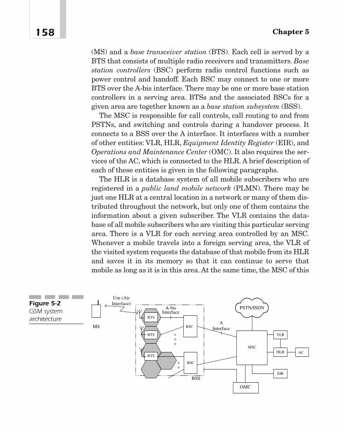
(MS) and a base transceiver station (BTS). Each cell is served by aBTS that consists of multiple radio receivers and transmitters. Basestation controllers (BSC) perform radio control functions such aspower control and handoff. Each BSC may connect to one or moreBTS over the A-bis interface. There may be one or more base stationcontrollers in a serving area. BTSs and the associated BSCs for agiven area are together known as a base station subsystem (BSS).
The MSC is responsible for call controls, call routing to and fromPSTNs, and switching and controls during a handover process. Itconnects to a BSS over the A interface. It interfaces with a numberof other entities: VLR, HLR, Equipment Identity Register (EIR), andOperations and Maintenance Center (OMC). It also requires the ser-vices of the AC, which is connected to the HLR. A brief description ofeach of these entities is given in the following paragraphs.
The HLR is a database system of all mobile subscribers who areregistered in a public land mobile network (PLMN). There may bejust one HLR at a central location in a network or many of them dis-tributed throughout the network, but only one of them contains theinformation about a given subscriber. The VLR contains the data-base of all mobile subscribers who are visiting this particular servingarea. There is a VLR for each serving area controlled by an MSC.Whenever a mobile travels into a foreign serving area, the VLR ofthe visited system requests the database of that mobile from its HLRand saves it in its memory so that it can continue to serve thatmobile as long as it is in this area. At the same time, the MSC of this
Chapter 5158
PSTN/ISDN
BTS
ooo
BTS
IWF
BTS
BSC
BSCoo
VLR
HLR AC
EIR
MSC
AInterface
A-bisInterface
BSS
OMC
MS
Um (AirInterface)Figure 5-2
GSM systemarchitecture

foreign serving area informs the HLR of the home system about thelocation of this mobile so that the home area of this subscriber canroute the call correctly when necessary.
The authentication center verifies the identity of the user at callinception times for security purposes, and contains such parametersas authentication keys and other required parameters. The EIR con-tains the International Mobile station Equipment Identity (IMEI)numbers of all mobile stations that are registered. Each mobile isassigned a unique IMEI number that can be used to determinewhether the equipment is genuine or not. The OMC is a centralizednetwork management system that provides the capability of remotesystem administration and maintenance of all equipment and data-bases, and may also perform such functions as billing and so on.
Figure 5-3 shows the functional block diagram of a GSM system.A brief description of the system is presented here. Each functionalblock will be further explained in the next section.
Figure 5-3(a) represents the transmitter of a mobile station. Thespeech signal from a mobile terminal is encoded into 13-bit uniformpulse code modulation (PCM) samples and applied to the input of aRPE-LTP coder [1]—[5]. It is in fact a linear predictive coder, or avocoder as it is called, that attempts to predict the incoming speechby modeling the speech-generating system by a finite-order, time-varying digital filter.2 The RPE-LTP encoder actually consists of two
159The GSM System and General Packet Radio Service (GPRS)
Speech fromMobile Station 13-bit PCM
EncoderRPE-LTPEncoder
ChannelCoder
InterleaverGMSK
Modulator
Up Converter& PowerAmplifier
Amplifier &Demodulator Deinterleaver Channel
Decoder
13-bit PCMto 8-bit A-
law EncoderTo MSCRPE-LTP
Decoder
RF Input atBase Station
(a)
(b)Data
Speech
Figure 5-3The functionalblock diagram of aGSM system
2In other words, the vocoder tries to mimic the vocal system of a human being. SeeReferences [1] to [5].

linear predictive filters, and generates a residual excitation (that is,a difference signal between the incoming speech and predictedspeech), which is multiplexed with the coefficients of the two filtersand passed to the channel encoder. Because there are 260 bits at theoutput of the encoder for every 20 ms of the speech input, the bit rateof a full-rate coder is 13 kb/s.
The purpose of the channel encoder is to provide some protectionagainst impairments that are likely to be introduced by the channel.This is done by encoding the incoming frames into error-correctingcodes. GSM uses a combination of block codes and convolutionscodes. An (n, k) block code encodes a k-bit message block into an n-bitcode by adding n � k parity bits. A convolutional code of rate 1/2 witha constraint length of 5 is used for speech. For 9.6 kb/s data, convo-lutional codes are the same, but a few bits are deleted from eachframe (resulting in punctured codes) so as not to exceed the data rateof the physical channel. If the data rate is 2.4 kb/s, the convolutionalcode is rate 1/6, but has the same constraint length. Not all bits of thespeech encoder output are equally critical to the subjective quality ofspeech at the receiver. Bits that are most essential to intelligibility ofspeech are protected against channel errors by encoding them intoboth block codes and convolutional codes. If there are any errors inthese bits that the receiver cannot correct, they are discarded. Bitsthat are less critical are encoded into convolutional codes only. Theremaining bits are transmitted without any channel coding. A 20 msframe at the output of the channel encoder contains 456 bits.
The output of the channel encoder is applied to an interleaver,which simply rearranges the order of the incoming bits.3 As men-tioned previously, speech or data is transmitted in frames, as shownin Figure 5-4. Each frame consists of eight slots, each of which isassigned to an individual user. Later on, we will see how exactly thedata structure of a slot is constructed. For the time being, though, itis sufficient to say that each slot contains 114 bits of the interleaveroutput and 42.5 bits of overhead.
Chapter 5160
3Correlated signal fading, which is a characteristic of a mobile radio channel, resultsin burst errors. The purpose of the interleaver is to spread out in time these bursterrors so that the receiver can detect and correct them with a higher probability.Notice that the data rate at the output of the interleaver is the same as the input.
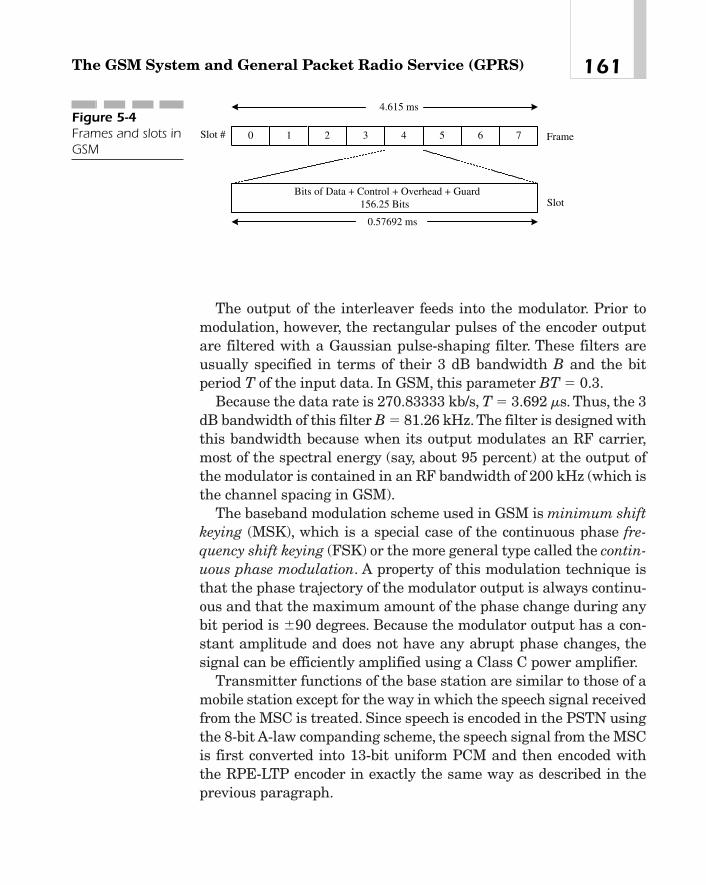
The output of the interleaver feeds into the modulator. Prior tomodulation, however, the rectangular pulses of the encoder outputare filtered with a Gaussian pulse-shaping filter. These filters areusually specified in terms of their 3 dB bandwidth B and the bitperiod T of the input data. In GSM, this parameter BT � 0.3.
Because the data rate is 270.83333 kb/s, T � 3.692 ms. Thus, the 3dB bandwidth of this filter B � 81.26 kHz.The filter is designed withthis bandwidth because when its output modulates an RF carrier,most of the spectral energy (say, about 95 percent) at the output ofthe modulator is contained in an RF bandwidth of 200 kHz (which isthe channel spacing in GSM).
The baseband modulation scheme used in GSM is minimum shiftkeying (MSK), which is a special case of the continuous phase fre-quency shift keying (FSK) or the more general type called the contin-uous phase modulation. A property of this modulation technique isthat the phase trajectory of the modulator output is always continu-ous and that the maximum amount of the phase change during anybit period is �90 degrees. Because the modulator output has a con-stant amplitude and does not have any abrupt phase changes, thesignal can be efficiently amplified using a Class C power amplifier.
Transmitter functions of the base station are similar to those of amobile station except for the way in which the speech signal receivedfrom the MSC is treated. Since speech is encoded in the PSTN usingthe 8-bit A-law companding scheme, the speech signal from the MSCis first converted into 13-bit uniform PCM and then encoded withthe RPE-LTP encoder in exactly the same way as described in theprevious paragraph.
161The GSM System and General Packet Radio Service (GPRS)
4.615 ms
0 7 Frame
Slot
1 2 3 4 5 6
0.57692 ms
Slot #
Bits of Data + Control + Overhead + Guard156.25 Bits
Figure 5-4Frames and slots inGSM
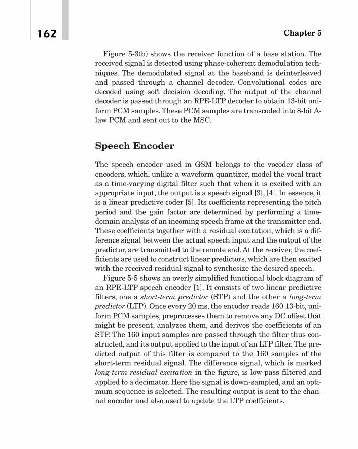
Figure 5-3(b) shows the receiver function of a base station. Thereceived signal is detected using phase-coherent demodulation tech-niques. The demodulated signal at the baseband is deinterleavedand passed through a channel decoder. Convolutional codes aredecoded using soft decision decoding. The output of the channeldecoder is passed through an RPE-LTP decoder to obtain 13-bit uni-form PCM samples. These PCM samples are transcoded into 8-bit A-law PCM and sent out to the MSC.
Speech Encoder
The speech encoder used in GSM belongs to the vocoder class ofencoders, which, unlike a waveform quantizer, model the vocal tractas a time-varying digital filter such that when it is excited with anappropriate input, the output is a speech signal [3], [4]. In essence, itis a linear predictive coder [5]. Its coefficients representing the pitchperiod and the gain factor are determined by performing a time-domain analysis of an incoming speech frame at the transmitter end.These coefficients together with a residual excitation, which is a dif-ference signal between the actual speech input and the output of thepredictor, are transmitted to the remote end. At the receiver, the coef-ficients are used to construct linear predictors, which are then excitedwith the received residual signal to synthesize the desired speech.
Figure 5-5 shows an overly simplified functional block diagram ofan RPE-LTP speech encoder [1]. It consists of two linear predictivefilters, one a short-term predictor (STP) and the other a long-termpredictor (LTP). Once every 20 ms, the encoder reads 160 13-bit, uni-form PCM samples, preprocesses them to remove any DC offset thatmight be present, analyzes them, and derives the coefficients of anSTP. The 160 input samples are passed through the filter thus con-structed, and its output applied to the input of an LTP filter. The pre-dicted output of this filter is compared to the 160 samples of theshort-term residual signal. The difference signal, which is markedlong-term residual excitation in the figure, is low-pass filtered andapplied to a decimator. Here the signal is down-sampled, and an opti-mum sequence is selected. The resulting output is sent to the chan-nel encoder and also used to update the LTP coefficients.
Chapter 5162

The output of the encoder consists of three components: (i) theSTP coefficients, also known as the reflection coefficients, (ii) thequantized long-term residual excitation, and (iii) the LTP coeffi-cients. Because it is these parameters and not the actual speechsamples that are eventually transmitted to the remote end, the bitrate of these kinds of coders is generally much less than those of anywaveform coders, such as PCM, Adaptive Differential PCM(ADPCM), and so on, which try to replicate the speech signaldirectly at the remote end.
Actually, the 20 ms short-term residual signal is divided into four5 ms blocks, which are then analyzed one at a time to compute theLTP coefficients and generate the long-term residual excitation. Sim-ilarly, the LTP coefficients are also updated once every 5 ms. Thus,once every 5 ms, there are 47 bits of the long-term residual outputand 9 bits of LTP coefficients. To reduce quantization errors, eachreflection coefficient x is mapped to a value before trans-mission. A 20 ms speech signal results in 36 bits of STP coefficients.Thus altogether, there are 47�4 � 9�4 � 36 � 260 bits in a 20 msframe, resulting in a bit rate of 13 kb/s.
Channel Encoder
Besides speech, various types of signaling and control information aswell as circuit-switched data at different rates (such as 9.6, 2.4 kb/s,
log 11 � x1 � x 2
163The GSM System and General Packet Radio Service (GPRS)
Speech (20 msSamples)
PredictedSignal
Short-TermFilter
Long-TermPredictor
Filter
Low-PassFilter
Decimator+-
160 Samples ofShort-Term
Residual Signal
Long-TermResidual
Excitation
Short-Term Filter Coefficients (Reflection Coefficients)
Quantized Long-Term Residual
Excitation
Long-TermLag and Gain
47 Bits Every 5 ms
9 Bits Every 5 ms
36 Bits Every 20 ms
Figure 5-5A simplified blockdiagram of theRPE-LTP speechencoder

and so on) are transmitted over the air interface. Examples are pag-ing messages, synchronization information, information that amobile station can use to correct its frequency, and so on. In eachcase, it may be necessary to employ a different channel codingscheme. By way of examples, we will describe the channel-encodingprocedures only for full-rate speech and 9.6 kb/s data.
Channel Encoding for Full-Rate Speech Every 20 ms, thespeech encoder generates 260 bits. These bits are classified in orderof their importance as Class 1a, Class 1b, and Class 2 types. BecauseClass 1a bits are the most important, they are first encoded in ablock code to add 3 bits of parity so that errors not corrected by theconvolutional decoder can be detected. Any block that fails the par-ity check is discarded by the receiver. Class 1b bits are also channel-encoded, but do not have any parity bits. However, four tail bits areadded so that the last bit of the input data is correctly encoded bythe convolutional coder. Class 2 type bits are transmitted over thechannel without any encoding. This is shown in Figure 5-6.
Channel Encoding for 9.6 kb/s Data The encoding procedurefor circuit-switched data on a traffic channel is shown in Figure 5-7. Here, every 20 ms, 240 bits of user data are multiplexed with 4tail bits and applied to the input of a convolutional encoder of rate1/2 and constraint length 5. Thirty-two bits are then removed fromthe output of the encoder. This is called the punctured coding.
In either case, the output of the channel encoder is 456 bits, whichare interleaved and transmitted over 8 TDMA frames using a fixedslot in all frames.
Chapter 5164
53 Bits
Speech Samples(Every 20 ms) RPE-LTP
Encoder
Class 1a -50 bits
Class 1b -132 Bits
Class 2 - 78 Bits
CRCEncoder
MUX
ConvolutionalEncoder Rate 1/2,
Constraint Length 5
4 Tail Bits136 Bits MUX
456 Bits
378 Bits
Figure 5-6Channel coding offull-rate speech
TEAMFLY
Team-Fly®

Interleaving
The purpose of the interleaver is to scramble, or spread out in time,clustered errors resulting from correlated signal fading. We shalldescribe the interleaving procedure by way of an example. Considerfirst the speech traffic. The output of the speech coder appears in 20ms blocks, each consisting of 260 bits. Each block, when encoded bythe channel encoder, results in 456 bits at its output.
Figure 5-8 depicts how contiguous blocks can be interleaved. The456-bit output from the encoder corresponding to a 20 ms interval iswritten into a 57�8-bit memory by row from left to right and fromtop to bottom, and read out column by column, as shown in Figure5-8(b). The result is 8 subblocks, which are numbered 1 through 8 inFigure 5-8(c), each containing 57 bits. Thus, any two adjacent bits ofthe interleaver input are now spaced apart by 57 bit periods.
To achieve further interleaving, the eight subblocks of any block,say, m, are transmitted over eight frames, the first four frames beingshared between blocks, say, m-1 and m, and the last four framesbeing shared by blocks m and m�1 as depicted in Figure 5-8(c).Assuming that slot k is assigned to a given user, subblock 5 of blockm and subblock 1 of block m�1 are inserted into slot k of frame n.Similarly, slot k of frame n�1 contains subblock 6 of block m andsubblock 2 of block m�1, and so on for frames n�2 and n�3. In thesame way, although it is not shown in the figure, subblocks 1 through4 of block m and subblocks 5 through 8 of block m-1 of the interleaveroutput are transmitted over slot k of frames n-4, n-3, n-2, and n-1.Because each block of the channel encoder output is transmitted ineight bursts using eight consecutive TDMA frames, the interleaver issaid to have depth eight. A similar interleaving process is used foruser data or signaling and control information.
165The GSM System and General Packet Radio Service (GPRS)
240 bits of Data(Every 20 ms)
Multiplexer244 Bits Convolutional
Encoder Rate 1/2,Constraint Length 5
4 Tail Bits
488 Bits Puncturing32 bits
456 BitsFigure 5-7Channel coding of9.6 kb/s data
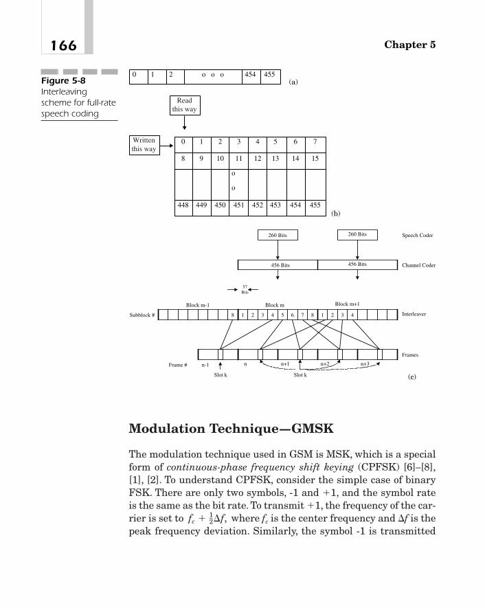
Modulation Technique—GMSK
The modulation technique used in GSM is MSK, which is a specialform of continuous-phase frequency shift keying (CPFSK) [6]—[8],[1], [2]. To understand CPFSK, consider the simple case of binaryFSK. There are only two symbols, -1 and �1, and the symbol rateis the same as the bit rate. To transmit �1, the frequency of the car-rier is set to where fc is the center frequency and �f is thepeak frequency deviation. Similarly, the symbol -1 is transmitted
fc � 12¢f,
Chapter 5166
0 1 2 454 455 o o oFigure 5-8Interleavingscheme for full-ratespeech coding
o
o
0 1 2 3 4 5 6 7
8 9 10 11 12 13 14 15
448 449 450 451 452 453 454 455
Writtenthis way
Readthis way
Channel Coder
Speech Coder
Interleaver
260 Bits 260 Bits
456 Bits 456 Bits
57Bits
Frames
Slot k
Block m Block m+1Block m-1
Subblock # 1 2 3 45
n+2
7 81 2 3 4
Frame # n n+1
6
n+3n-1
8
Slot k
(a)
(b)
(c)

by setting the carrier frequency to Notice that in thiscase, depending upon the incoming data, the carrier frequency maychange abruptly once every symbol period. Similarly, the phase ofthe carrier also changes in discrete steps. For example, it changesby p�f if the symbol is �1 and by �p�f if the symbol is �1. A con-sequence of this discontinuity is that the power spectral density ofthe modulated signal contains large side lobes outside the mainlobe. Thus, to preserve the integrity of the signal at the receiver,very often a larger bandwidth is needed than is usually available inthe system.
To prevent the occurrence of these side lobes and thus minimizethe bandwidth requirement, the carrier frequency may be changedcontinuously by a carefully chosen modulating signal. For example,the FM signal may be written as
(5-1)
where m(t) is the modulating signal. Since the baseband signal inGMSK is passed through a Gaussian filter before applying it to themodulator, m(t) will not have any discontinuity. The important thingto observe in equation 5-1, though, is that even if m(t) is discontin-uous, its integral is continuous, and thus the phase of the modulatedsignal is always continuous. That is why it is called continuous-phase FSK.
In the above expression, the modulation index is defined as
�FSK � where Rb is the bit rate. For orthogonal detection of FSK
signals, the minimum frequency deviation is �fmin � 0.25Rb corre-sponding to bFSK � 0.5. The two carrier frequencies are, therefore, fc
� 0.25Rb and fc � 0.25Rb. In this case, the bandwidth required isminimized, and the CPFSK modulation is termed MSK.
There are a number of ways to construct an MSK signal. Forexample, the modulated signal during any symbol period may begiven by
(5-2)y1t 2 � mI cos apttb cos vct � mQ sin apt
tb sinvct
2¢fRb
,
y1t 2 � A cos a2pfct � 2p¢f�t
0
m1t¿ 2dt¿b
fc � 12¢f.
167The GSM System and General Packet Radio Service (GPRS)
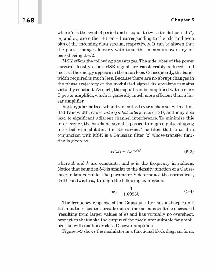
where T is the symbol period and is equal to twice the bit period Tb.mI and mq are either �1 or �1 corresponding to the odd and evenbits of the incoming data stream, respectively. It can be shown thatthe phase changes linearly with time, the maximum over any bitperiod being �p/2.
MSK offers the following advantages. The side lobes of the powerspectral density of an MSK signal are considerably reduced, andmost of the energy appears in the main lobe. Consequently, the band-width required is much less. Because there are no abrupt changes inthe phase trajectory of the modulated signal, its envelope remainsvirtually constant. As such, the signal can be amplified with a classC power amplifier, which is generally much more efficient than a lin-ear amplifier.
Rectangular pulses, when transmitted over a channel with a lim-ited bandwidth, cause intersymbol interference (ISI), and may alsolead to significant adjacent channel interference. To minimize thisinterference, the baseband signal is passed through a pulse-shapingfilter before modulating the RF carrier. The filter that is used inconjunction with MSK is a Gaussian filter [2] whose transfer func-tion is given by
(5-3)
where A and k are constants, and v is the frequency in radians.Notice that equation 5-3 is similar to the density function of a Gauss-ian random variable. The parameter k determines the normalized,3-dB bandwidth v0 through the following expression:
(5-4)
The frequency response of the Gaussian filter has a sharp cutoff.Its impulse response spreads out in time as bandwidth is decreased(resulting from larger values of k) and has virtually no overshoot,properties that make the output of the modulator suitable for ampli-fication with nonlinear class C power amplifiers.
Figure 5-9 shows the modulator in a functional block diagram form.
v0 �1
1.6986k
H1v 2 � Ae�k2v2
Chapter 5168

Logical ChannelsAs we have indicated before, many different types of information arerequired to be transmitted in GSM. To do this, the concept of logicalchannels is used. Broadly, there are two types of logical channels,traffic and control.
� Traffic Channels (TCH) These channels may be full-rate orhalf-rate. The full-rate traffic channels are used for encodedspeech at 22.8 kb/s or user data at rates of 12 kb/s, 6 kb/s, and3.6 kb/s. The half-rate channels are intended for encoded speechat a lower bit rate, such as 11.4 kb/s, and user data at 4.8 and2.4 kb/s.
� Signaling Channels There are three categories of thesechannels:
A. Broadcast Control Channel (BCCH) As the name implies, itis a point-to-multipoint channel in the downlink direction,and carries system and cell-related information identifyingthe network and cells, information used in cell selection andhandoff, the current control channel configuration para-meters, and so on. There are actually two channels here:� Synchronization Channel (SCH) that broadcasts infor-
mation so that a mobile station can synchronize to the basestation
169The GSM System and General Packet Radio Service (GPRS)
� Input Data Gaussian
Filter
X
X
Cos tc
Sin tc
OutputS/P Converter +Symbol Mapper
X
X
Im
Qm
cos( / )t Tb
sin( / )t Tb
ωπ
π ω
Figure 5-9A functional blockdiagram of a GMSKmodulator using adigital Gaussianfilter

� Frequency Correction Channel (FCCH) that enables mobilestations to adjust their frequencies when necessary.
B. Common Control Channels (CCH) There are three channelsin this category:� Paging Channel (PCH) This downlink, point-to-multipoint
channel is used to broadcast paging messages to mobilestations.
� Random Access Channel (RACH) This is an uplink, point-to-point channel over which mobile stations send a callorigination request or response to a page using a multiple-access, slotted Aloha scheme. Because more than one usermay access the channel simultaneously, there is some non-zero probability of collision, in which case users must backoff and wait a random period before seizing the channelagain.
� Access Grant Channel (AGCH) The purpose of thisdownlink, point-to-point channel is to indicate to arequesting mobile station which traffic channel or whichstand-alone dedicated control channel it is being assigned.
C. Dedicated Control Channels (DCCH) There are two types ofthese channels:� Stand-alone Dedicated Control Channel (SDCCH) This is
a point-to-point channel and operates on both uplinks anddownlinks at 1/8 of the data rate of a traffic channel.4 Amobile station may use it for such things as registration,authentication, or location updates before it is assigned atraffic channel. After the assignment of the traffic channel,SDCCH must be relinquished.
� Associated Control Channel (ACCH) This type of channelis associated with a traffic channel. There are two channelsof this type—the slow and the fast. The slow associatedcontrol channel (SACCH) is used by a mobile station to
Chapter 5170
4This rate is achieved by transmitting the information only once every eight TDMAframes.
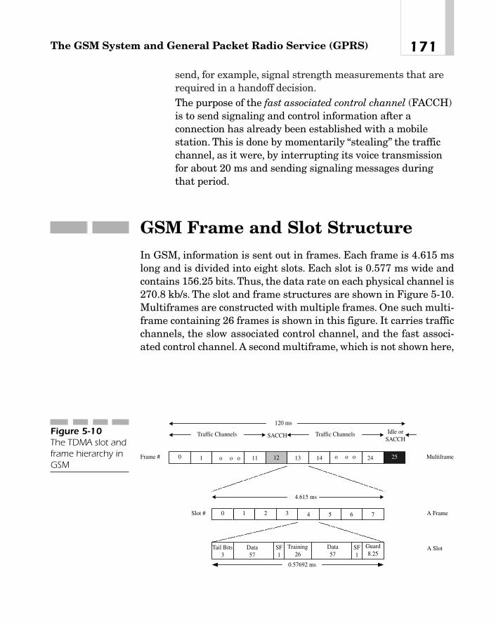
send, for example, signal strength measurements that arerequired in a handoff decision.
� The purpose of the fast associated control channel (FACCH)is to send signaling and control information after aconnection has already been established with a mobilestation. This is done by momentarily “stealing” the trafficchannel, as it were, by interrupting its voice transmissionfor about 20 ms and sending signaling messages duringthat period.
GSM Frame and Slot StructureIn GSM, information is sent out in frames. Each frame is 4.615 mslong and is divided into eight slots. Each slot is 0.577 ms wide andcontains 156.25 bits. Thus, the data rate on each physical channel is270.8 kb/s. The slot and frame structures are shown in Figure 5-10.Multiframes are constructed with multiple frames. One such multi-frame containing 26 frames is shown in this figure. It carries trafficchannels, the slow associated control channel, and the fast associ-ated control channel. A second multiframe, which is not shown here,
171The GSM System and General Packet Radio Service (GPRS)
4.615 ms
0 7 A Frame
A Slot
1 2 3 4 5 6
0.57692 ms
Frame # 0 111 o o o o o o12
120 ms
Idle orSACCH
SACCH
13 14 24 25
Traffic Channels Traffic Channels
Multiframe
Slot #
Tail Bits3
Data57
Data57
Guard8.25
Training26
SF1
SF1
Figure 5-10The TDMA slot andframe hierarchy inGSM
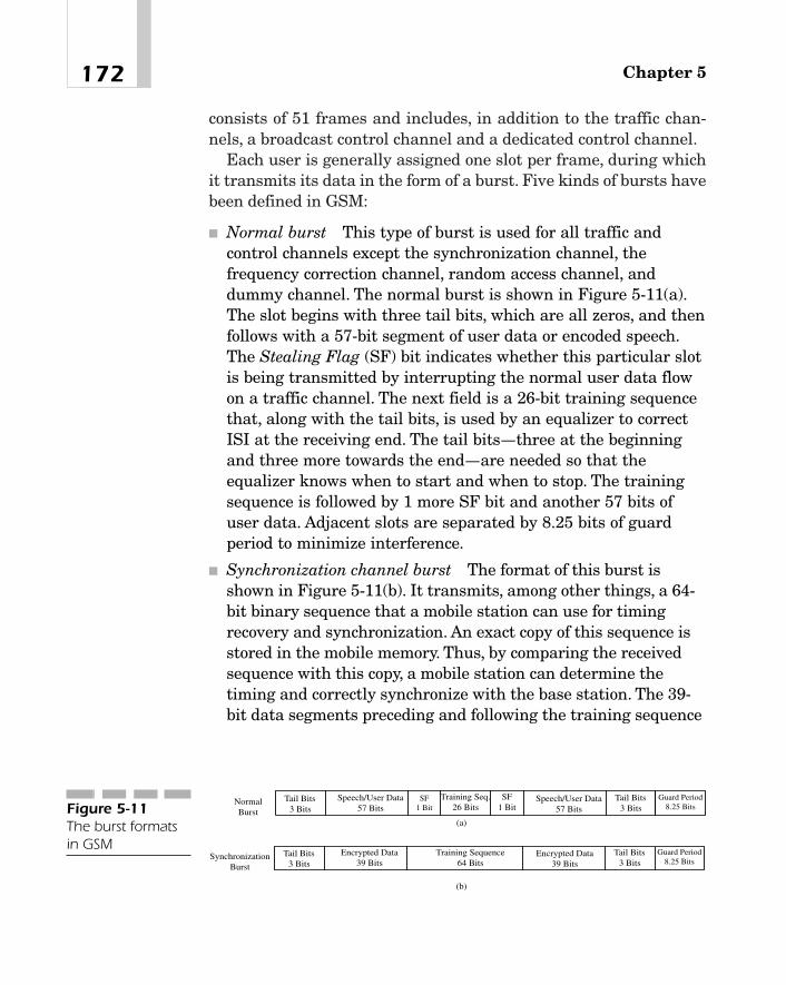
consists of 51 frames and includes, in addition to the traffic chan-nels, a broadcast control channel and a dedicated control channel.
Each user is generally assigned one slot per frame, during whichit transmits its data in the form of a burst. Five kinds of bursts havebeen defined in GSM:
� Normal burst This type of burst is used for all traffic andcontrol channels except the synchronization channel, thefrequency correction channel, random access channel, anddummy channel. The normal burst is shown in Figure 5-11(a).The slot begins with three tail bits, which are all zeros, and thenfollows with a 57-bit segment of user data or encoded speech.The Stealing Flag (SF) bit indicates whether this particular slotis being transmitted by interrupting the normal user data flowon a traffic channel. The next field is a 26-bit training sequencethat, along with the tail bits, is used by an equalizer to correctISI at the receiving end. The tail bits—three at the beginningand three more towards the end—are needed so that theequalizer knows when to start and when to stop. The trainingsequence is followed by 1 more SF bit and another 57 bits ofuser data. Adjacent slots are separated by 8.25 bits of guardperiod to minimize interference.
� Synchronization channel burst The format of this burst isshown in Figure 5-11(b). It transmits, among other things, a 64-bit binary sequence that a mobile station can use for timingrecovery and synchronization. An exact copy of this sequence isstored in the mobile memory. Thus, by comparing the receivedsequence with this copy, a mobile station can determine thetiming and correctly synchronize with the base station. The 39-bit data segments preceding and following the training sequence
Chapter 5172
Tail Bits3 Bits
Speech/User Data57 Bits
SF1 Bit
Training Seq.26 Bits
SF1 Bit
Speech/User Data57 Bits
Tail Bits3 Bits
Guard Period8.25 Bits
NormalBurst
Tail Bits3 Bits
Encrypted Data39 Bits
Training Sequence64 Bits
Tail Bits3 Bits
Guard Period8.25 Bits
SynchronizationBurst
Encrypted Data39 Bits
(a)
(b)
Figure 5-11The burst formatsin GSM
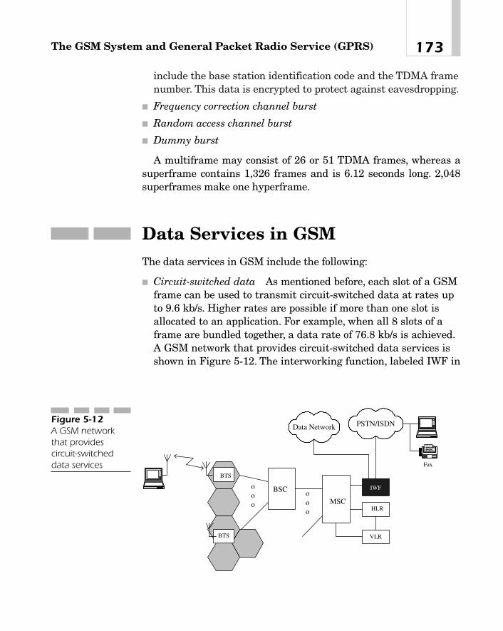
include the base station identification code and the TDMA framenumber. This data is encrypted to protect against eavesdropping.
� Frequency correction channel burst
� Random access channel burst
� Dummy burst
A multiframe may consist of 26 or 51 TDMA frames, whereas asuperframe contains 1,326 frames and is 6.12 seconds long. 2,048superframes make one hyperframe.
Data Services in GSMThe data services in GSM include the following:
� Circuit-switched data As mentioned before, each slot of a GSMframe can be used to transmit circuit-switched data at rates upto 9.6 kb/s. Higher rates are possible if more than one slot isallocated to an application. For example, when all 8 slots of aframe are bundled together, a data rate of 76.8 kb/s is achieved.A GSM network that provides circuit-switched data services isshown in Figure 5-12. The interworking function, labeled IWF in
173The GSM System and General Packet Radio Service (GPRS)
PSTN/ISDNData Network
BTS
ooo
MSC
BTS VLR
HLR
IWF
Fax
ooo
BSC
Figure 5-12A GSM networkthat providescircuit-switcheddata services

the figure, interfaces GSM to a private or public network suchas a PSTN, ISDN, circuit-switched public data network, packet-switched public data network, and so on. Because the datacommunication protocols of a mobile station may be differentfrom those of devices it is in communication with across anetwork, entity IWF may perform protocol conversion, rateadaptation, and so on.
� Short messaging service A mobile station in GSM may transmitor receive short alphanumeric messages during both idle andactive call states.
� GPRS This is a new service available with GSM Phase 2� thatenables multiple users to transmit packet data over a single slot.In this section, we will present a brief description of GPRS.
General Capabilities and Features of GPRS
In circuit-switched data services, when a user wants to transmit orreceive any data, first a physical channel is set up using the normalGSM call control procedures. Because data usually comes in burstsseparated by variable periods of inactivity, the channel may remainidle for a considerable length of time, depending upon the type ofdata services being used. One could, of course, release the channelduring inactive periods of data and reestablish the connection whenuser data is ready. However, this approach is not very efficient orpractical, because delays associated with call control procedures forsetting up a physical channel are relatively long. A packet switchingsystem, where multiple users may transmit their data over thesame physical channel using the so-called virtual circuits, over-comes this problem by taking advantage of the statistical nature ofthe traffic arrival process. The virtual circuits may be either perma-nent or switched. But even when they are switched, call controldelays for setting up or tearing down a virtual circuit are usuallyvery small.
As we mentioned before, GPRS is a new feature of GSM that pro-vides the capability of packet mode transmission of user data andsignaling information using the existing GSM network and radioresources. Each physical channel is shared by multiple users. The
Chapter 5174
TEAMFLY
Team-Fly®

channel access mechanism has been optimized for intermittent,short bursts as well as large volumes of data, allowing data to betransmitted within about 0.5 to 1.0 seconds of a reservation request.It supports both IP and X.25 protocols and real-time as well as non-real-time data. Both point-to-point and point-to-multipoint commu-nications are possible. There is no restriction on the transfer of SMSmessages over GPRS channels.
In packet switching, it is necessary to use a set of data communi-cation protocols so that the transmission is efficient and error-free.Protocols that are of interest here are usually the lower-layer proto-cols such as the logical link control (LLC) and medium access control(MAC).
Users are allowed to request a desired quality of service (QoS)from the network. However, only a limited number of QoS profilesare supported. Different modes of operation are possible. For exam-ple, in one mode, a mobile station can receive both GSM and GPRSservices simultaneously (that is, a voice call and packet mode datatransfer at the same time). In another mode, it can only receive theGPRS service. In the third mode, the mobile station monitors controlchannels of both GSM and GPRS, but can receive services from onlyone of them at a time (that is, either a voice or packet mode data).Four channel-coding schemes, designated CS-1, CS-2, CS-3, and CS-4, with coding rates of 1/2, 2/3, 3/4, and 1, respectively, are supported.The throughput depends on the coding scheme used: with CS-1, themaximum throughput is about 9 kb/s, whereas with CS-4, it is 21.4kb/s. Because a user may be assigned all eight slots of a frame, theper-user throughput may be in excess of 160 kb/s.
GPRS Network Architecture
Figure 5-13 is the architecture of a general GPRS network. Theinterface points between different elements of the network have alsobeen indicated. To see the difference between a GSM and a GPRSnetwork, compare this figure with Figure 5-2. Notice that in GPRS,there are only two new entities:
� Serving GPRS Support Node (SGSN) As the name implies, theSGSN provides GPRS services to a mobile station in the serving
175The GSM System and General Packet Radio Service (GPRS)

area of its associated MSC. A PLMN may have more than oneSGSN, in which case, the SGSNs are connected together over anIP-based Gn interface. Two different PLMNs, on the other hand,are connected over a Gp interface. A serving GSN connects to agateway GSN via a Gn interface and to its BSS over a Gbinterface that uses the Frame Relay protocol at the link layer.
An SGSN node locates mobile stations subscribing to GPRSservices and adds this information to the HLR. Another functionof the SGSN is to control user access to the network byperforming authentication using the same encryption keys andalgorithm as in GSM. Optionally, it can also perform signalingand control for non-GPRS services. For example, it can supportshort messaging service over a GPRS radio channel andefficiently process paging messages and mobile locationinformation required in GSM circuit-switched calls.
Chapter 5176
HLRMSCA
SGSN 1
PSTN/ISDN
PDN1 (e.g.The
Internet)GGSN
Gb Gs
Gn
GiAnotherPLMN
Gp
Gr
Gc
PDN2
Gi
SGSN 2Gn
To otherPDN
o o
To otherSGSN
BSSVLR
SMS-GMSC
Gd
D
CE
TE MTUm
R
PLMN
GGSN
Figure 5-13The architecture ofa GPRS network

� Gateway GPRS Support Node (GGSN) GGSN provides aninterface between a GPRS network and any external networksuch as a packet-switched public data network (PSPDN). Thus,as an example, whenever a PSPDN has a packet to send to aPLMN, it comes first to the GGSN. The gateway GSN containsthe routing information of all mobile stations attached to it andforwards an incoming packet appropriately en route to itsdestination. It may request information from an HLR or provideinformation to the HLR when necessary. Both SGSN and GGSNhave IP routing functionality, and as such may be connectedtogether by an IP router.
In the current version of cellular systems (that is, 2G�), GPRS issupported by adding packet-handling capabilities to the base stationcontroller. This is done by means of an interface called packet controlunit (PCU) as shown in Figure 5-14. In a fully evolved 3G system, theinterface to a GPRS network would be integrated into the UTRA BSS.
GPRS Protocol Stacks
The GPRS protocol stacks required in a mobile station, BSS, SGSN,and GGSN, are shown in Figure 5-15. Although the networking
177The GSM System and General Packet Radio Service (GPRS)
HLRMSC
SGSN
PSTN/ISDN
The Internet GGSN
BSC VLRBTS
PCU
Figure 5-14Support of GPRS in2G� networks

protocol is shown in the figure to be either IP or X.25, GPRS is fullycapable of supporting applications based on any standard data pro-tocol.
GPRS protocols at various layers are thoroughly described in Ref-erences [14]—[22]. Here, we provide only a short description of theprotocol at each layer:
� Subnetwork Dependent Convergence Protocol (SNDCP) SNDCP,which, in the protocol hierarchy, lies between the network layer(that is, IP/X.25) and the LLC layer, takes the network layerPDUs (corresponding to different protocols) and converts theminto a format that is suitable for transmission over theunderlying radio interface network. For example, if the protocolat the layer above it is IP, the SNDCP will take the IP packet,compress its header, and pass it to the LLC layer. Similarly,when it receives a packet from the LLC layer, it maydecompress the header and pass it to the IP layer. User packetsmay have variable lengths and are segmented, if necessary.Both acknowledged and unacknowledged data transfer ispossible. Other functions performed at this layer include� Data transfer using negotiated QoS profiles� Security and encryption of user data and control to provide
protection against eavesdropping
� Logical Link Control (LLC) The data link layer at the mobilestation (the Um reference point) consists of two sublayers: the
Chapter 5178
MS BSS SGSN GGSNUm Gb Gn Gi
Application
IP/X.25
SNDCP
LLC
RLC
MAC
GSM PhysicalLayer
Physical Layer
RLC
MAC
GSM PhysicalLayer
RLC
MAC
RLC
MAC
Physical Layer
Frame Relay
Relay
BSSGP
Physical Layer
Frame Relay
BSSGP
LLC
SNDCP
L2
IP
TCP/UDP
GTP
Physical Layer
L2
IP
TCP/UDP
GTP
IP/X.25
Relay
Figure 5-15GPRS protocolstacks at a fewreference points

upper sublayer known as LLC and the lower sublayer consistingof a radio link control (RLC) and a MAC sublayer. The LLCsublayer is based on the link access procedures of the ISDN Dchannel (LAPD) and supports procedures for the following:� Unacknowledged data transfer. The Frame Relay protocol is a
subset of LAPD procedures using the unacknowledgedinformation transfer mode.
� Acknowledged data transfer.� Flow control.� Error recovery using sequence numbering in the acknowledged
transfer mode.� Ciphering of logical link PDUs in both acknowledged and
unacknowledged transfer modes.
� RLC The RLC protocol provides a reliable transmission of datablocks over the air interface using a selective automatic repeatrequest (ARQ)-type procedure, where data blocks received inerror are retransmitted by the source.
� MAC The MAC sublayer controls access of the physicalmedium by mobile stations using a slotted Aloha scheme byresolving contention among multiple users or among multipleapplications of an individual user and then granting therequested access in a manner that ensures efficient utilization ofbandwidth.
� GPRS Tunneling Protocol (GTP) In GPRS, address and controlinformation are added to protocol data units so that they can berouted within a PLMN or between two PLMNs. The protocol thatdefines this process is known as the GTP.5 Simultaneous
179The GSM System and General Packet Radio Service (GPRS)
5The term tunneling is used to mean encapsulating an original packet with a newheader. Its use is quite common in packet-switched networks. Suppose that an IPv6packet has to be sent over a network that is using the older IPv4 protocol. In this case,we could take the original IPv6 packet, add the IPv4 header to it, and send the result-ing packet over the network. That would be called tunneling. Another example is IPover ATM where an IP packet, when it first enters an ATM device, is encapsulatedwith an 8-octet header before it is sent out over ATM.

operation of two modes is possible—unacknowledged mode forUDP/IP and acknowledged mode for TCP/IP.
� Relay function It provides a procedure for forwarding a packetreceived at a node to the next node en route to its destination. Inthe BSS, LLC PDUs are relayed between Um and Gb interfaces.In the SGSN, packet data protocol (that is, IP and X.25) PDUsare relayed between interfaces Gb and Gn.
� Base Station System GPRS protocol (BSSGP) The function ofthis protocol is to provide multiple, connectionless, layer 2 linksand to transfer data, QoS-specifying parameters, and routinginformation between a base station and an SGSN.
� Frame Relay This is the link layer protocol on the Gb interface.Data is transmitted over one or more permanent virtual circuits(PVCs). Frames received in error are discarded. The data linkconnection identifier is two octets long. The maximum framesize is 1,600 octets.
The physical layer on the Um interface includes the typical,GSM radio link functions such as framing, channel encoding, inter-leaving, modulation, wave-shaping, synchronization, timing recov-ery, and so on.
For a description of TCP and IP protocols, see Reference [10].Figure 5-15 also indicates the need for protocol conversion at dif-
ferent points in the network. For example, consider the servingGSN. After receiving a packet from the base station system, it mustterminate the five lower layers—physical, frame relay, BSSGP, LLC,and SNDCP—and retrieve the network protocol data units (PDUs).These IP/X.25 PDUs must then be encapsulated in GTP, TCP/UDP,IP, and L2 in that order and sent out over its physical layer toGGSN.
Packet Structures
The packet structure at each layer of the Um interface is shown inFigure 5-16. PDUs received from the IP or X.25 layer for transmis-sion over the air interface are segmented at the SNDCP layer intosmaller packets and passed to the LLC layer where a header and
Chapter 5180

frame check sequence are added to each segment.The maximum sizeof the LLC data unit is 1,600 octets. Each LLC PDU is further seg-mented, if necessary, into smaller blocks before passing it to theRLC/MAC layer. To each of these blocks are added an RLC header, aMAC header, and a block check sequence (BCS).The resulting frame,after the usual physical-layer processing, is sent out in normalbursts, each consisting of 156.25 bits, of which 114 bits are from anRLC/MAC PDU.
Logical Channels
Broadly speaking, there are three types of logical channels for trans-mitting packets in GPRS.They are packet broadcast control channel,packet common control channel (PCCH), and traffic channels. Someoperate only on uplinks, some on downlinks, and the rest on bothuplinks and downlinks (that is, they’re bidirectional).
Uplink Channels Packet Random Access Channel (PRACH) Thisis a common control channel and is used by a mobile station to starta packet transfer process or respond to a paging message.
181The GSM System and General Packet Radio Service (GPRS)
Network LayerPDU
Header + User Data + CRC if needed
Segment 1 Segment 2 Segment No o o
Header FCSLLC Data Unit LLC PDU
SNDCP Layer
o o o
Segmentation
Segmentation
1 no o o
RLC/MAC Data (or Signaling) BCS RLC/MAC PDU
Coding, Interleaving, etc. Physical Layer
Transmitted over Air Interface in Bursts
RLC HeaderMAC Header
Figure 5-16Packet structure atdifferent protocollayers at the Uminterface

Downlink Channels Packet Broadcast Control Channel (PBCCH)It broadcasts system-specific parameters to all mobile stations in aGPRS serving cell.
The following are common control channels:
� Packet Paging Channel (PPCH) The GPRS network uses thischannel to transmit paging messages before sending userpackets.
� Packet Access Grant Channel (PAGCH) When a mobile stationwants to initiate a data transfer, it transmits a Packet ChannelRequest message on a PRACH or on a RACH in the absence of aPRACH. In reply, the base station sends a Packet ImmediateAssignment message on a PAGCH, reserving one or more packetdata transfer channels for that mobile station. Similarly, thenetwork may send on this channel a resource assignmentmessage to a mobile station.
� Packet Notification Channel (PNCH) This channel is used tonotify a group of mobile stations prior to sending packets tothose stations in a point-to-multipoint fashion.
Bidirectional Channels A Packet Data Transfer Channel(PDTCH) is allocated to a mobile station for transferring their datapackets. A given user may request, and be granted, more than onePDTCH.
A Packet Associated Control Channel (PACCH) carries signalinginformation, such as an acknowledgment (ACK), in response to a datablock transfer, a resource assignment message in response to aresource request, or power control information. Only one PACCH isassigned to each mobile station, and is associated with all packet datatransfer channels that may be allocated to that station.
Logical channels are multiplexed at the MAC layer onto physicalchannels on a block-by-block basis. Physical channels used for GPRSpacket data transmission are known as packet data channels (PDCH).
Packet Transmission Protocol
Multiple users may transmit packets on a PDCH on a time-sharedbasis. Each PDCH consists of one time slot of a TDMA frame. How-
Chapter 5182

ever, a mobile station may be assigned up to eight PDCHs for packetdata transmission.
A cell may permanently set aside a fraction of its available physi-cal channels exclusively for packet data transmission and the restfor the usual voice traffic. Alternatively, it may use a dynamic allo-cation scheme whereby one or more channels out of its available poolof channels are allocated to packet data transmission on a demandbasis, and are deallocated and returned to the pool when there is nolonger any need for them.The number of packet data channels activeat any time depends on the number of simultaneous users and thevolume of traffic generated by each user. However, there must be atleast one PDCH to enable transfer of control and signaling informa-tion (as well as user data if necessary). It is not necessary that thesame PDCH be used to send packets to/from a given mobile station.
Multiple users transmit on a PDCH using a slotted Aloha, multi-ple-access reservation scheme. In the event of transmission errors,an ARQ protocol is used that provides error recovery by selectiveretransmissions of RLC blocks. To this end, GPRS employs the con-cept of a temporary block flow (TBF), which is actually a physicalconnection between a mobile station and the network, allowing thetransfer of RLC/MAC blocks.6 Each RLC data block or RLC/MACcontrol block includes in its header a temporary flow identifier (TFI)that indicates the TBF to which the block belongs.7 Furthermore, alldownlink RLC/MAC blocks contain in their header an uplink stateflag (USF) that indicates which mobile station (or application) canuse the next uplink RLC block on the same time slot. In this way, dif-ferent mobile stations may be multiplexed on the same PDCH whennecessary.
A mobile station transfers packets to an SGSN following the statediagram of Figure 5-17. The corresponding state machine represen-tation of an SGSN is similar.
In the IDLE state, a mobile station may select or reselect a cell,but its location or routing information is not available to the SGSN.
183The GSM System and General Packet Radio Service (GPRS)
6It is temporary because it exists only as long as there is an RLC/MAC block to sendand is removed when it is no longer needed.7On any PDCH, the same TFI may be used in the uplink and downlink directions.Similarly, different PDCHs may use the same TFI.

In other words, it is not attached to the mobility management func-tion, and therefore cannot receive or originate a call.
When the mobile station establishes a logical link to an SGSN, itenters the READY state. The mobile is now attached to the mobilitymanagement function and can initiate a mobile-originated call on aPRACH (that is, a packet random access channel) or monitor thepacket-paging channel to see if there is any packet transfer requestfrom the network. If there is no PRACH available yet, the GPRS-attached mobile station may use the GSM common control channel.After being allocated appropriate resources from the network, themobile station can begin to transmit and receive packets.
The mobile station remains in the READY state as long as thereis any packet to send. Even when there is no packet pending in itsbuffer, it may continue in the READY state for a certain length oftime that is marked by starting an associated timer. As the timer isrunning, the network has the capability to preempt the timer andforce the mobile station into the STANDBY state. When the timerexpires, the mobile station changes to the STANDBY state. While inthe READY state, the mobile station may power down by performinga GPRS-detach procedure. It then enters the IDLE state, whereuponthe SGSN deletes the location and routing information of the mobile.
In the STANDBY state, the mobile station is still GPRS-attachedand sends the SGSN its location and routing information periodi-cally and each time it moves into a new routing area (RA). While inthis state, it can transmit a PDU and then transition to the READYstate.
The packet transfer procedure when initiated by a mobile stationis shown in Figure 5-18. The mobile station sends a packet channelrequest over a packet random access channel (or in its absence, a
Chapter 5184
IDLE READY STANDBY
GPRS Attach
GPRS Detach
Timer Expiryor Forced to Standby
PDU Transmission
Figure 5-17A state machinemodel of thepacket datatransfer function ofa mobile station
TEAMFLY
Team-Fly®

random access channel). The network replies by reserving the nec-essary resources required by the MS and sending a packet immedi-ate assignment message. In this case, the access method completesin a single phase. In a two-phase access procedure, when the net-work sends a packet immediate assignment, it reserves only theresources required by a mobile station to transmit a packet resourcerequest. Consequently, the mobile station sends this request mes-sage indicating resources it needs, whereupon the network makesthe necessary reservation and replies with a packet resource assign-ment message.
After receiving the packet immediate assignment, the MS canbegin to send data packets. The network may withhold acknowledg-ment until after receiving a few packets. When it receives a block inerror (say, block 3 in this example), it sends an ACK (4,5), excludingblock 3 from this acknowledgment, as shown in Figure 5-18. In thiscase, the mobile station performs a selective retransmission of block3 only (and not blocks 3, 4, and 5), transmitting it along with block 6.Alternatively, the network could send a NACK in the event of anerror.
The packet transfer procedure initiated by the network (that is, anSGSN) is shown in Figure 5-19. The mobile station monitors the
185The GSM System and General Packet Radio Service (GPRS)
Packet Channel Request on RACH or PRACH
Data Block 1 on PDTCH
Packet Immediate Assignment on AGCH or PAGCH
Data Block 2 on PDTCH
ACK (1,2) on PACCH
Data Block 3 on PDTCH
Data Block 4 on PDTCH
GPRS Network
ACK (4,5) on PACCH
Data Block 3 on PDTCH
Data Block 6 on PDTCH
ACK (3,6) on PACCH
MS
Data Block 5 on PDTCH
Figure 5-18Packets in a mobile-originated transferin a GPRS system

packet paging-channel (or in its absence, the paging channel). Whenit receives a packet-paging request, it sends a packet channelrequest. The network answers by sending a packet immediateassignment. This is followed by a packet-paging response from theMS and a packet resource assignment. At this point, the networkmay begin to transmit data blocks to the MS.
SummaryIn this chapter, we have presented a brief description of the GSM sys-tem. Its features and capabilities have been summarized, and sometechnical detail has been provided about the speech encoder, channelencoder, interleaver, modulator, TDMA slot, frame formats, and logi-cal channels. One of the important aspects of GSM is its data servicecapability such as the short messaging service and circuit-switched
Chapter 5186
Packet Channel Request on RACH or PRACH
Packet Paging Response on PACCH
Packet Immediate Assignment on AGCH or PAGCH
Packet Resource Assignment on AGCH, PAGCH or PACCH
Data Block 1 on PDTCH
Data Block 2 on PDTCH
ACK (1, 2) on PACCH
Data Block 3 on PDTCH
Data Block 4 on PDTCH
ACK (4) on PACCH
Data Block 3 on PDTCH
Data Block 5 on PDTCH
Packet Paging Request on PCH or PPCH
ACK(3,5) on PACCH
MS GPRS NetworkFigure 5-19Packets in anetwork-initiatedtransfer in a GPRSsystem

data. In the short messaging service, users can transmit messages ofabout 160 alphanumeric characters in both point-to-point and point-to-multipoint fashion. The circuit-switched data rate per slot may be2.4, 4.8, or 9.6 kb/s. By bundling multiple channels, a user can be pro-vided much higher data rates, say, up to about 76.8 kb/s. The GPRSis a relatively new feature of GSM Version 2.5� that provides packetmode data services at rates of 8 to 20 kb/s per slot. In this chapter, wehave described the general capabilities and features of GPRS, its net-work architecture, protocols at various layers, logical channels,packet structures, and the packet transmission protocol.
References[1] A. Mehrotra, GSM System Engineering. Norwood, MA:
Artecth House, 1997.
[2] T.S. Rappaport, Wireless Communications. New Jersey: Pren-tice Hall, 1996, pp. 501–529.
[3] N.S. Jayant, “High-Quality Coding of Telephone Speech andWideband Audio,” IEEE Comm. Mag., Vol. 28, No. 1, pp.10–19, January 1990.
[4] P. Vary, et al., “Speech Codec for the European Mobile RadioSystem,” Proc. ICASSP ‘88, pp. 227–230, April 1988.
[5] J. Makhoul, “Linear Prediction: A Tutorial Review,” Proc.IEEE, Vol. 63, pp. 561—580, April 1975.
[6] R.W. Lucky, et al., Principles of Data Communications. NewYork: McGraw Hill, 1968, pp. 200–202.
[7] J.G. Proakis, Digital Communications. New York: McGrawHill, 1968, pp. 172–186.
[8] C. Sundberg, “Continuous Phase Modulation,” IEEE Comm.Mag., pp. 25–38, April 1986.
[9] J. Cai and D.J. Goodman, “General Packet Radio Service,”IEEE Comm. Mag., pp. 122–131, October 1997.
[10] M. Naugle, Network Protocol Handbook. New York: McGraw-Hill, 1994.
187The GSM System and General Packet Radio Service (GPRS)

ETSI Standards[11] GSM 03.60: GPRS Service Description, Stage 2.
[12] GSM 03.64: Overall Description of the GPRS Radio Interface,Stage 2.
[13] GSM 04.60: GPRS, Mobile Station—Base Station System(BSS) Interface, Radio Link Control/Medium Access Control(RLC/MAC) Protocol.
[14] GSM 04.64: GPRS, Logical Link Control.
[15] GSM 04.65: GPRS, Subnetwork Dependent Convergence Pro-tocol (SNDCP).
[16] GSM 07.60: Mobile Station (MS) Supporting GPRS.
[17] GSM 08.08: GPRS, Mobile Switching Center—Base StationSubsystem (MSC-BSC) Interface: Layer 3 Specification.
[18] GSM 08.14: Base Station Subsystem—Serving GPRS Sup-port Node (BSS-SGSN) Interface; Gb Interface Layer 1.
[19] GSM 08.16: Base Station Subsystem—Serving GPRS Sup-port Node (BSS-SGSN) Interface; Network Service.
[20] GSM 08.18: Base Station Subsystem—Serving GPRS Sup-port Node (BSS-SGSN); Base Station Subsystem GPRS Pro-tocol (BSSGP).
[21] GSM 09.60: GPRS Tunneling Protocol (GTP) Across the Gnand Gp Interface.
[22] GSM 09.61: General Requirements on Interworking Betweenthe Public Land Mobile Network (PLMN) Supporting GPRSand Packet Data Network (PDN).
[23] GSM 2.01, Version 4.2.0, January 1993.
[24] ETSI/GSM Section 4.0.2, “European Digital CellularTelecommunication System (Phase 2); Speech ProcessingFunctions: General Description,” April 1993.
Chapter 5188

Universal Mobile Telecommunications
System (UMTS)
CHAPTER 66
Copyright 2002 M.R. Karim and Lucent Technologies. Click Here for Terms of Use.
As we indicated in Chapter 1, “Introduction,” the European Telecom-munications Standards Institute (ETSI)/Special Mobile Group (SMG)developed two standards for International Mobile Telecommunicationin the year 2000 (IMT-2000). One of them is the Universal MobileTelecommunications System (UMTS) Wideband Code Division Mul-tiple Access (W-CDMA), which is based upon a direct-sequence CDMA(DS-CDMA) technology and operates in the frequency division duplex(FDD) mode. The other is the UMTS TDD system, which is based ontime-division CDMA (TD-CDMA) principles. The purpose of thischapter is to present an overview of the W-CDMA UMTS system asspecified in the ETSI standards documents [1]—[40].
The chapter is organized as follows. We begin with a synopsis ofthe UMTS system features and follow it up with the third-generation(3G) wireless network architecture. The UMTS uses a layered proto-col architecture at different interface points, each layer performing aset of specific functions. We present an overview of the radio inter-face protocol stack. The next few sections describe each of the con-stituent protocols of this stack, namely the physical layer, themedium access control, radio link control, the packet data conver-gence protocol, the broadcast multicast protocol, and the radioresource control protocol. Topics, such as the synchronization proce-dure, power controls, and handovers, are also described. The mater-ial of this chapter has been drawn from a series of standardsdocuments. In many instances, our descriptions have been necessar-ily brief and comprehensive. However, we have included relevant ref-erences at the end of the chapter so that the interested reader mayconsult them for greater detail.
System FeaturesThe UMTS operates in two modes—FDD and Time Division Duplex(TDD). In both modes of operation, the information is transmittedusually in 10 ms frames. In FDD, two distinct frequency bands, sep-arated by a guard band, are used—one for the uplink and the otherfor the downlink transmission. In TDD, on the other hand, the samefrequency band is used for transmissions in both directions. More
Chapter 6190

specifically, in this mode, each frame consists of a number of syn-chronized time slots, some of which are dedicated to uplink and therest to downlink transmissions. The difference between the twomodes is illustrated in Figure 6-1.
The UMTS has been allocated a bandwidth of 120 MHz in theFDD mode and 35 MHz in the TDD mode in the 2000 MHz spectrumrange. When operating as paired bands as shown in Figure 6-1(a),the transmitter and receiver frequencies in all user equipment (UE)must be spaced apart by 190 MHz. As we mentioned earlier in thebook, CDMA uses Direct Sequence Spread Spectrum (DSSS).Because one of the goals of 3G systems is to provide multimedia andhigh-speed data services at rates up to 2 Mb/s, the nominal channelbandwidth is 5 MHz. A service provider may, however, adjust thechannel bandwidth if necessary to optimize the spectrum utilization.The center frequency must be an integer multiple of 200 kHz.1 Thechip rate for spectrum spreading is 3.84 Mc/s.
191Universal Mobile Telecommunications System (UMTS)
Uplink
Frequency (MHz)
Guard Bandwidth
Time
Uplink Downlink
(a)
Downlink
Synchronized Time Slots
(b)
1920 1980 2110 21701960 2150
5Paired BandsFigure 6-1
The two modes ofUMTS: (a) The FDDmode and (b) TheTDD mode
1This is called channel raster.

W-CDMA is an asynchronous system where base stations do nothave to maintain a system-wide reference time scale. However, eachcell or each sector of a cell must now use a different scrambling code.Because there is no global timing reference, the time offsets betweensignals received from multiple users by a base station in such a sys-tem may be quite significant. Since the cross-correlation betweenscrambling codes assigned to different users is no longer zero, thereceived signal from any user depends not only on the signal fromthat user but also on the signals received from all other users over anumber of consecutive symbol periods. Thus, multiuser detectionwould be useful in such a system.2 In contrast, cdmaOne is synchro-nous because all base stations in the system use a reference timethat is based on the Global Positioning System (GPS) time derivedfrom the Universal Coordinated time. More specifically, the I and Qchannels at any base station in cdmaOne are spread by two maxi-mal-length pilot pseudonoise sequences with an offset that is uniquefor that base station.This simplifies and accelerates cell searching ata mobile station.
The following specifications apply to the radio transmission andreception in the UMTS FDD mode. The separation between theuplink and downlink frequency bands must be in the range of 134.8to 245.2 MHz. The maximum transmitter power of the user equip-ment is in the range of 21 to 33 dBm (that is, 125 mW to 2 W). Thereceiver sensitivity, which is nominally defined as the minimumreceiver input power at the antenna port such that the bit error ratio(BER) is 0.001 or less, is �117 dBm for the UE and �121 dBm for abase transceiver station.3 With transmit power control (TPC) com-mands, the UE adjusts its transmitter power output by 8 to 12 dB insteps of 1 dB, by 16 to 24 dB in steps of 2dB and by 16 to 26 dB insteps of 3 dB. A base station, on the other hand, adjusts its transmitpower by 8 to 12 dB in steps of 1 dB and by 4 to 6 dB in steps of 0.5dB. These features are summarized in Table 6-1.
Chapter 6192
2Multiuser detection principles are briefly described in Chapter 3, “Principles of Wide-band CDMA (W-CDMA).”3The receiver sensitivity at a base station may be less because its performance can beimproved using multipath diversity, adaptive antenna arrays, or multiuser detectiontechniques.

Wireless Network ArchitectureIn many instances, standards documents describe protocols andinterfaces at some well-defined reference points. A general networkarchitecture with these reference points is shown in Figure 6-2. Thenetwork may be partitioned into two broad entities—the UniversalTerrestrial Radio Access Network (UTRAN) and the core network.The UTRAN is responsible for establishing connections between UEand the rest of the network. A Radio Network Controller (RNC) is
193Universal Mobile Telecommunications System (UMTS)
Spectrum allocation FDD mode: 1850—1910 MHz for uplink,2110—2170 for downlink.TDD mode: 1900—1920 MHz and 2010—2025MHz. Each of these bands for the TDDmode is used for both uplink and downlinktransmissions.
Channel spacing 5 MHz
Center frequency Integral multiples of 200 kHz
Separation between uplink 134.8—245.2 MHzand downlink frequency bands
Chip rate 3.84 Mc/s
Modes FDD and TDD
Transmitter power output of UE 21, 24, 27, or 33 dBm
Receiver sensitivity �121 dBm for base stations and �117 dBmfor UE at a bit error rate of 10�3
Power control steps 1, 2, or 3 dB for UE and 0.5 or 1 dB for basestations
Maximum possible change in 26 dB for UE and 12 dB for base stationsthe transmit power level on TPC commands
Data rates 144 kb/s in rural outdoor, 384 kb/s inurban/suburban outdoor, 2 Mb/s in indoor orlow-range outdoor
Table 6-1
W-CDMA systemfeatures

connected to one or more Base Transceiver Stations (BTS) or nodes,each of which serves a cell. The function of an RNC is to control radioresources. For example, it would assign frequencies, spreading andscrambling codes, the power levels of the various channels, and so on.The interface point between an RNC and a node is Iub. The userequipment accesses the UTRAN via the base station located in theserving cell.A Radio Network Subsystem (RNS), consisting of an RNCwith its associated nodes, connects to the core network (CN) at a ref-erence point Iu. Similarly, notice the interface point between twoRNCs.An RNS is either the whole UTRAN, or only a part thereof thatprovides connections to a UE and includes only one RNC. For eachUE connected to the network, only one RNS (called the serving RNS)controls the connections. However, other RNSs may assist the servingRNS as the mobile moves from one cell to another. Such an RNS iscalled a drift RNS.
With the exception of the Multimedia Processing Equipment(MPE), the 3G-core network is very similar to the core network of aGSM with General Packet Radio Service (GPRS) capabilities. Adetailed description of a GSM and GPRS network may be found in
Chapter 6194
BTS(Node)
BTS(Node)
BTS(node)
BTS(node)
RNC
RNC
MPE
ooo
ooo
Core Network
Access Network
MSC
VLR
HLR
IWF
SGSN
GGSN
ooo
ooo
MS
Uu
Iu
Iur
Iub
PSTN PDN
RNS
RNS
Figure 6-2A general UMTSnetworkarchitecture withvarious interfacereference points
TEAMFLY
Team-Fly®

Chapter 5, “The GSM System and General Packet Radio Service(GPRS).” The MPE performs such functions as code conversionbetween audio coding, video coding, and control and signaling stan-dards that might be used in a completely general network to provideinteroperability amongst different multimedia terminals used in thesystem.
A UTRAN may consist of a number of RNSs. In the previous fig-ure, there are two.
Radio Interface Protocol Stack—An OverviewThe UMTS uses a layered protocol architecture at different interfacepoints, each layer performing a set of specific functions. These archi-tectures are usually described in terms of the control plane and userplane protocols. The control plane protocols are concerned with thesignaling and control required to establish a connection between aUE and the network, or request specific services or resources fromthe network. The user plane protocols, on the other hand, specifyhow the user data is to be transferred across an interface after a con-nection has been established between the UE and the network.
Figure 6-3 shows the protocol architecture of the UTRAN. It isalso the lower-layer protocols on UE. On the UTRAN side, the phys-ical layer, which is responsible for carrying the information bits, isprovided by the BTS while the other layers reside in an RNC. TheRadio Resource Control (RRC) is a layer 3 protocol in the controlplane that interfaces with the radio link control (RLC) sublayer oflayer 2 and terminates in the UTRAN. It deals with two types of con-trol and signaling messages—those that are generated at the higherlayers and others that are generated in the RRC itself. The first typeis nonaccess stratum (NAS) messages, which originate at a UE andterminate in the core network or vice versa. The RRC layer simplypasses these NAS messages to the higher layers or to the RLC layerbelow en route to the physical layer. Examples of these messagesinclude system information provided by the core network that needsto be broadcast to all UEs, signaling functions such as call control
195Universal Mobile Telecommunications System (UMTS)

and mobility management, and so on. Signaling messages of the sec-ond type that originate at the RRC layer are associated with suchfunctions as assigning radio resources (such as a common packetchannel or codes), requesting a UE to perform measurements,reporting the results, and so on. Another function of the RRC layer isto configure all lower layers—all layer 2 sublayers as well as thephysical layer, that is, the Packet Data Convergence Protocol (PDCP),broadcast/multicast control (BMC), RLC, media access control(MAC), and the physical layer. It does this by setting up direct com-munication links to these layers in addition to the interfaces shownin the figure.
User information is transferred between the higher layers and thephysical layer via layer 2, which can be partitioned into a number of
Chapter 6196
Higher Layer
User PlaneControl Plane
RRC Sublayer
PDCP
BMC
Physical Layer (Physical Channels)
Layer 2
RLC
MAC
Logical channels
Transport channels
Higher Layers
User InformationVoice/Data
Radio NetworkLayer
Signaling and Control
ConfigurationControl
Figure 6-3The layeredprotocols at theUTRAN
sublayers—the PDCP, the BMC, the RLC, which is similar to thewell-known logical link (LLC) protocol, and the MAC sublayer. Sep-arate logical channels are used to transfer different types of infor-mation between RLC and MAC layers. Similarly, the MAC sublayerand the physical layer exchange information by means of a numberof transport channels, each of which may have some defining char-acteristic. For example, some transport channels carry only uplinkdata, while others are configured only on the downlinks. Or, onetransport channel may carry only system and cell-specific informa-tion that needs to be broadcast over an entire cell, while another isused to broadcast only the paging information, and so on.As we shallsee, it is at the physical layer that these channels are multiplexed, ora coded, composite transport channel is demultiplexed.
The user data (such as the packet mode data) originates at theapplication layer and is encoded according to some higher-layer pro-tocols such as the Transmission Control Protocol (TCP) at the trans-port layer and Internet Protocol (IP) at the network layer. Theencoded data is eventually passed via layer 2 to the physical layerwhere the data stream is further processed before it is sent out overthe radio link. For example, it is encoded into a forward error-cor-recting code, interleaved, spread out with an orthogonal channeliza-tion code, and then modulates a carrier. Similarly, the signal receivedover the radio interface is demodulated, despread, deinterleaved, anddecoded for error detection and correction. The physical layer deliv-ers the resulting data to the MAC layer where it is further processedand then forwarded to the upper layers. Other functions performedat the physical layer include multiplexing various transport chan-nels, demultiplexing coded composite transport channels, frequencyand time synchronization, power control, and rate matching.4
197Universal Mobile Telecommunications System (UMTS)
4As we shall see later in greater detail, power control is the process of controlling thetransmitter power of a mobile station so that a base transceiver station receives anequal signal level from all mobile stations in the cell, thereby preventing a singlemobile (which may happen to be closer to the base station) from swamping out the sig-nals from other mobiles.
Rate matching means adjusting the data rate on a transport channel by repeatingor deleting some bits so that the resulting data rate is equal to the data rate of thephysical channel to which the transport channel is being mapped.

Any given layer provides services to its immediate upper layer viaa logical point, called a service access point (SAP), using a set of prim-itives that includes REQUEST, INDICATION, ACK, and CONFIR-MATION in acknowledged data transfers but only REQUEST andINDICATION in the unacknowledged mode. In Figure 6-4, when theMAC layer wants to send a packet to its peer entity at the other endof the air interface, it sends a REQUEST to the layer below. Thephysical layer at the receiving end, on receiving the packet, sends anINDICATION to its MAC layer, which then sends an ACK to itsphysical layer. On receipt of this ACK, the physical layer at the send-ing end sends a CONFIRMATION to the previous MAC layer.
Physical LayerThe purpose of the physical layer is to condition the digital data fromhigher layers so that it can be transmitted over a mobile radio chan-nel reliably. In the transmit direction, it performs such functions aschannel coding, interleaving, scrambling, spreading, and modulation.In the receive direction, these functions are reversed so that thetransmitted data is recovered at the receiver. The MAC layer deliv-ers user data and signaling over a number of transport channels.
Chapter 6198
RE
QU
EST
MAC Layer
Physical Layer
MAC Layer
Physical Layer
IND
ICA
TIO
N
AC
K
CO
NFI
RM
AT
ION
Peer Entitites
Air Interface
Figure 6-4Use of primitives totransfer databetween peerentities in a systemwith layeredprotocols
The physical layer maps each of these channels into a physical chan-nel and transmits the information over the radio interface. A physi-cal channel is characterized by its associated carrier frequency,scrambling, and channelization codes, the radio frame length, andthe relative phase angle when meaningful. A radio frame is 10 mslong and consists of 15 time slots. Because the chip rate is 3.84 Mc/s,there are 38,400 chips in a frame and 2,560 chips in a slot. Exceptwhere otherwise indicated, the description of this section appliesonly to the FDD mode of UMTS.
Overview of Physical Layer Functions
The physical layer of the UMTS can be best explained in terms of thefunctions performed by a transmitter. Figure 6-5 shows a functionalblock diagram of a transmitter in the UE. In UMTS, the data arriveson a transport channel in blocks. We begin by encoding each of theseblocks of a transport channel into a cyclic redundancy check (CRC)code and then serially concatenating all encoded blocks of that chan-nel.5 Because the length of the resulting output may exceed the max-imum size, it may be necessary to segment it into a number ofsmaller code blocks and then pass them through a channel encoder,where the input stream is encoded into either a convolutional code ofrate 1/3 or 1/2 or turbo code of rate 1/3. Sometimes it may not be neces-sary to use any channel coding at all, in which case there is norestriction on the size of the code block, and therefore the segmenta-tion step may be omitted.
The output of the channel coder is applied to the first of two inter-leavers, where incoming bits are interleaved following certain rulessuch that the relative position of each bit in the output stream is dif-ferent from its position in the input.
199Universal Mobile Telecommunications System (UMTS)
5The generator polynomials of these codes may be one of the following:
g41x 2 � x8 � x7x4 � x3 � x � 1
g31x 2 � x12 � x11 � x3 � x2 � x � 1
g21x 2 � x16 � x12 � x5 � 1
g11x 2 � x24 � x23 � x6 � x5 � x � 1

The number of bits in a transport block is not constant, but gen-erally varies from one transmission time interval to another. In thedownlink direction, these variable-length blocks can be handled byinterrupting transmission when there are fewer bits to transmit. In
Chapter 6200
PhysicalChannel A
I
X X
X X
∑
ooo
1dC
3dC
dG
dG
X X
X X
∑
ooo
2dC
4dC
dG
dG
X
Q
ComplexScrambling
Code
+
j
CRCEncoder
ChannelCoder
Transport BlockConcatenation &
Segmentation
CRCEncoder
oo
Inter-leaver 1
RateMatch
Tr. Ch 1Block 1
Tr. Ch 1Block 2
A1
TransportChannel
Multiplexer
oo
TransportChannel 2
TransportChannel N
Inter-leaver 2
Transport-to-Physical
Channel Mapper
DPDCH1
PulseShaping
FilterX
X
o90
tc�cos
To PowerAmplifier
A2
A3 DPDCH2DPDCH3DPDCH4
DPCCH
X X
cC cG
DPDCH1
DPDCH3
DPDCH2
DPDCH4
DPCCH
SymbolMapper
0 to +1, 1 to -1
SymbolMapper
SymbolMapper
SymbolMapper
I + jQ
S jSx y+
IS QSx y−
QS ISx y+
PulseShaping
Filter
SymbolMapper
0 to +1, 1 to -1
X
∑
Figure 6-5A functional blockdiagram of atransmitter in theUE

an uplink, however, the resulting bit rate after transport channelsare multiplexed should be exactly matched to the available physicalchannel rate. This is achieved by passing the first interleaver outputthrough the functional block labeled Rate Match where, dependingupon the channel rate, bits are either repeated or deleted withoutloss of information (that is, by deleting or puncturing some codingbits).
The remaining physical-layer functions will be described ingreater detail later in this chapter. For the purpose of this overview,however, we shall present a brief description. All transport channelsare processed in exactly the same way as described previously, thenmultiplexed together, and interleaved using a second interleaver. Itis worth mentioning here that as far as the broadcast channel is con-cerned, there may be only one transport block during each trans-mission time interval.
Because the transmission time interval of any transport channelis usually longer than 10 ms, which is the length of a radio frame, anumber of consecutive radio frames may be required to transmit agiven transport block set. Thus, it is necessary that the bit sequenceat A1 contain an integral number of data segments of the same size.In the uplink direction, this is achieved, in a process called radioframe equalization, by appropriately padding the output of the chan-nel coder. Although not shown in the figure, it is this padded bitsequence that gets applied to the input of the first interleaver. Con-sequently, the bit stream at A2 can now be divided into a number ofequal segments that are suitable for transmission over consecutiveradio frames.
When more than one physical channel is involved, which is gener-ally the case, the bit sequence at A3 is split into the required physi-cal channels before applying it to the input of the second interleaver.This process is known as physical channel segmentation.
Different transport channels are mapped to different physicalchannels and separated into two distinct sets, say, the I and Q sets.The data associated with channel set I is transmitted on the in-phase (I) component of the signal. Similarly, the Q set data is trans-mitted on the quadrature (Q) component of the signal. In this figure,there are only four dedicated physical data channels (DPDCHs) andone dedicated physical control channel (DPCCH). To balance the
201Universal Mobile Telecommunications System (UMTS)

signal, the odd-numbered data channels are placed in the I set andthe even-numbered data channels together with the DPCCH in theQ set. The incoming data on each physical channel in either set isconverted into real-valued symbols—a binary one mapped to �1 anda binary zero to �1, thus in essence performing the BPSK modula-tion. However, because there are two channel sets, the net result isQPSK modulation.
Outputs of the symbol mappers are spread to the chip rate by real-valued channelization codes. These codes are orthogonal variablespreading factor (OVSF) codes or Walsh sequences, and are con-structed with the elements of a row of an orthogonal matrix, whoseentries are either �1 or �1, so that when channels are spread withdifferent OVSF codes, they become mutually orthogonal. To uniquelyidentify all physical channels at the receiver, each is spread with aseparate OVSF code. Different data rates are supported on a physi-cal channel by simply changing the spreading factor of the associ-ated code. The symbols, after spreading, are multiplied with a gainfactor that depends upon the relative power level at which the chan-nel is to be transmitted. The resulting outputs corresponding to alldifferent physical channels of the two sets are summed together,added in quadrature, and scrambled by a user-specific complexscrambling code. A complex code is selected for this purpose becauseit increases the average-to-peak power ratio. The real and imaginaryparts of the scrambler output are passed through wave-shaping fil-ters and modulate a CDMA carrier in the usual way.
The general structure of the BTS transmit functions (that is, onthe downlinks) is almost the same as Figure 6-5 and therefore willnot be discussed separately. Some of the differences between the twoare as follows. To provide balanced spreading, the data stream oneach downlink physical channel is split into two substreams, I and Q,corresponding, respectively, to the I and Q components of the signal.The two substreams are spread by the same channelization codebefore being scrambled by a cell-specific complex scrambling code.The radio frame equalization is not necessary here because higherlayers at the UTRAN can schedule the transmission at appropriateinstants or use proper spreading factors to ensure that the bitsequence after rate matching is an integral multiple of a radioframe.
Chapter 6202

Transport Channels
As we previously mentioned, the MAC layer periodically transfershigher-layer data to the physical layer in one or more transportblocks over a transport channel. A block size is given by the numberof bits in the block. The size of a transport block may be different ondifferent transport channels. The number of blocks exchanged eachtime between the MAC layer and the physical layer is called a trans-port block set. The interarrival time between two successive trans-port block sets is called the Transmission Time Interval (TTI). Theformat used for each transport block depends on the specific appli-cation. For speech, each transport block set contains only one trans-port block. For packet mode data, a set may consist of a variablenumber of transport blocks. For circuit-switched data, the number ofblocks per set is usually fixed during a call, but may be greater thanone. The TTI may also vary. For example, it is either 10 ms or 20 msfor speech, depending upon the coding rate of speech and 10/20/40/80ms for circuit or packet mode data. Figure 6-6 shows transportblocks of different sizes and their interarrival times.
A transport format consists of two parts—a dynamic part and asemistatic part. The dynamic part indicates the transport block sizein bits and the number of blocks in a set. The semistatic part speci-fies TTI, the type of channel coding (such as whether any channelcoding is to be used and, if so, the coding type) and the rate match-ing parameter. When a transport block is delivered to the physicallayer, it includes a label called a Transport Format Indicator (TFI)that specifies its format. The physical layer uses these TFIs associ-ated with all parallel transport channels to construct a TransportFormat Combination Indicator (TFCI) and sends it as part of a
203Universal Mobile Telecommunications System (UMTS)
TransportBlocks 1 4
TTI TTI TTI
2
3
5 6
Figure 6-6Transport blocksand the TTIbetweensuccessive blocks

control channel over the air interface so that the physical layer atthe receiving end knows how to demultiplex the transport channels.
The transport channels are summarized in Table 6-2. Broadlyspeaking, there are two types of transport channels: dedicated trans-port channels (DCH) that are unique to each user and commontransport channels that are shared by all users in a cell or a UTRAN.The dedicated channels employ inherent addressing of UE. Commonchannels use explicit addressing of UE when such addressing isrequired.
DCH DCHs are defined on both uplinks and downlinks, are avail-able in both FDD and TDD modes, and carry higher-layer data andcontrol information such as voice, video, handoff orders, and signalmeasurements destined to any desired user.
Common Transport Channels� Broadcast Channel (BCH) This is a downlink transport
channel that carries UTRAN system and cell-specific parameters
Chapter 6204
Transport Channel Direction Function
DCH Bidirectional Carries user data and control.
BCH Downlink Broadcasts system and cell-specificparameters.
PCH Downlink Transmits paging messages.
FACH Downlink Carries control information andshort data packets.
RACH Uplink Transmits signaling messages andshort data packets. Transmissionis subject to collision.
CPCH Uplink Carries user data packets. Mayexperience collision.
DSCH Downlink Carries user data and control.
Table 6-2
Summary oftransportchannels TE
AMFLY
Team-Fly®

such as random access codes, access slots in a cell, or diversitytypes used. The associated physical channel broadcasts theseinformation types over an entire cell. Each UE must decode thischannel before it can register with a cell. The channel usuallyoperates at a low data rate and high transmit power level.
� Paging Channel (PCH) This downlink transport channel isdesigned to carry paging messages for mobile-terminated calls.The physical layer transmits the information over one or morecells.
� Forward Access Channel (FACH) This is a downlink transportchannel and carries control information such as an acquisitionindication from a base station after a UE has randomly selectedan access slot on an available random access channel andtransmitted a preamble on that slot. It may also be used to carrya limited amount of packet data. The information is transmittedover an entire cell or part of a cell if the network design permitsit. There may be more than one FACH in a cell, each operating ata different data rate.
� Random Access Channel (RACH) This uplink transportchannel is available only in the FDD mode and carries signalingmessages (such as a mobile-originated call request) and somelimited amount of user data. The associated physical layer sendsthe information content of this channel by randomly selecting anavailable uplink access slot. Because this channel is accessed byall users in a cell, it is generally designed to operate at a low bitrate.
� Common Packet Channel (CPCH) The purpose of this uplinktransport channel is to carry packet data from a user. It operatesin much the same way as the random access channel. Forexample, a UE can begin to transmit during any predefinedinterval with respect to a received BCH frame. A downlinkdedicated channel provides power control and control commandsfor this channel. It is only available in the FDD mode.
� Downlink Shared Channel (DSCH) This downlink transportchannel is associated with one or more downlink dedicated
205Universal Mobile Telecommunications System (UMTS)
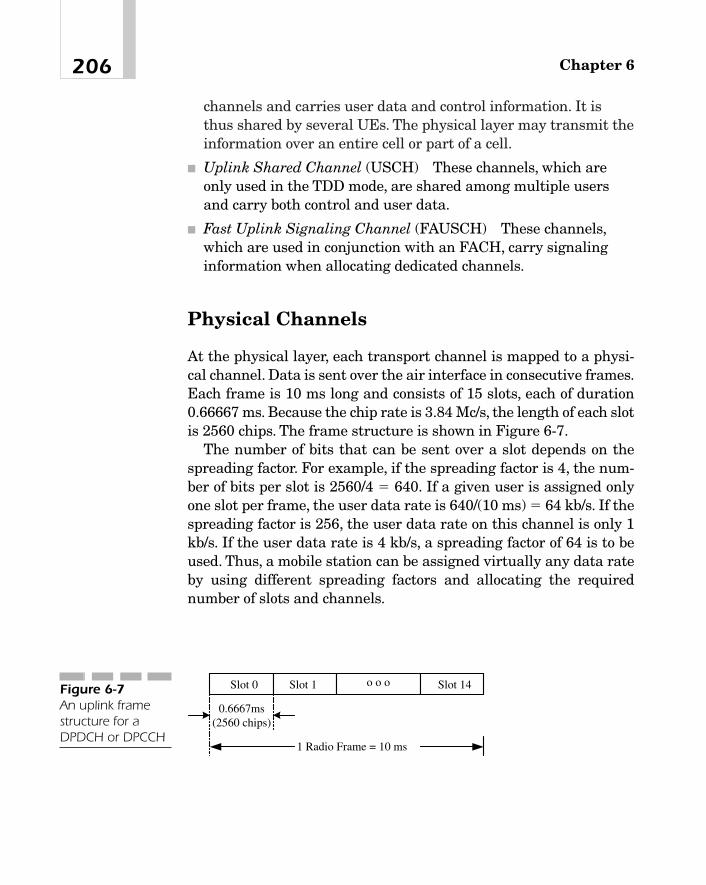
channels and carries user data and control information. It isthus shared by several UEs. The physical layer may transmit theinformation over an entire cell or part of a cell.
� Uplink Shared Channel (USCH) These channels, which areonly used in the TDD mode, are shared among multiple usersand carry both control and user data.
� Fast Uplink Signaling Channel (FAUSCH) These channels,which are used in conjunction with an FACH, carry signalinginformation when allocating dedicated channels.
Physical Channels
At the physical layer, each transport channel is mapped to a physi-cal channel. Data is sent over the air interface in consecutive frames.Each frame is 10 ms long and consists of 15 slots, each of duration0.66667 ms. Because the chip rate is 3.84 Mc/s, the length of each slotis 2560 chips. The frame structure is shown in Figure 6-7.
The number of bits that can be sent over a slot depends on thespreading factor. For example, if the spreading factor is 4, the num-ber of bits per slot is 2560/4 � 640. If a given user is assigned onlyone slot per frame, the user data rate is 640/(10 ms) � 64 kb/s. If thespreading factor is 256, the user data rate on this channel is only 1kb/s. If the user data rate is 4 kb/s, a spreading factor of 64 is to beused. Thus, a mobile station can be assigned virtually any data rateby using different spreading factors and allocating the requirednumber of slots and channels.
Chapter 6206
1 Radio Frame = 10 ms
Slot 0 Slot 1 o o o Slot 14
0.6667ms(2560 chips)
Figure 6-7An uplink framestructure for aDPDCH or DPCCH

Physical channels are different in different directions—theuplinks and downlinks, as listed in the following section.
Uplink Physical Channels Uplink Dedicated Physical Channels(Uplink DPCHs) fall into two categories—dedicated physical datachannels and dedicated physical control channels:
� Uplink DPDCH It carries the user information originating atthe higher layers. At any given time, a radio link may not haveany uplink DPDCH, or may have one or more of these channels,each using a different bit rate and hence a different spreadingfactor. For example, a DPDCH may have a data rate of 15, 30,60, 120, 240, 480, or 960 kb/s, using respectively, a spreadingfactor of 256, 128, 64, 32, 16, 8, or 4. The data rate, together withthe associated spreading factor to be used at a mobile station, isconfigured by the higher layers.
� Uplink DPCCH This uplink physical control channel transmitscontrol information at a rate of only 10 bits per slot with aspreading factor of 256. Thus, the data rate on this channel is 15kb/s. Its per-slot data structure is presented in Figure 6-8. Itconsists of four fields:� Pilot bits� The transport format combination indicator (TFCI)� The transmit power control command (TPC)� A feedback information field
There are 3 to 8 pilot bits that provide the receiver with areference carrier for coherent demodulation. The TFCI field,
207Universal Mobile Telecommunications System (UMTS)
Pilot Bits (3 - 8 bits)TFCI
(2 - 4 bits if present)
Feedback Infor- mation (1 or 2 bits if
present)TPC (1 or 2 Bits)
1 slot of a radio frame
Figure 6-8The per-slot datastructure of DPCCH
which was previously explained, indicates the format of atransport block set that is being transmitted over a DPDCH atthe same time as this DPCCH. This field may sometimes beabsent. If present, it may be 2, 3, or 4 bits long. The feedbackinformation bits provide information from UE to the UTRANon such things as the closed loop mode transmit diversity andsite selection diversity transmission [9]. This field also may attimes be absent. When present, it may have one or two bits. TheTPC field is always present and may be one or two bits long—either all 0s or all 1s. Unlike a DPDCH, there is only oneuplink DPCCH on each radio link. Clearly, a number of slotformats are possible depending upon the values of these fourfields. Which of these formats is being used is indicated by thehigher layers.
� Physical Random Access Channel (PRACH) Mobile stations usethis channel to send signaling information such as a callorigination request to the UTRAN and, if necessary, a smallamount of user data, such as short messages, alphanumerictexts, and so on. The access mechanism is based on the slottedAloha scheme [44]. There are 15 access slots in every two 10 msframes. Thus, the duration of each slot is 5,120 chips. Users waituntil the beginning of a slot and examine if it is idle. If it is, theystart transmitting. Clearly, in this case, there is some nonzeroprobability of collision; however, it is less than if the users hadstarted transmitting at any arbitrary point in a slot.
The information structure transmitted on PRACH is depicted inFigure 6-9. The transmission begins with one or more preamblesat slot boundaries and ends with a message part. Each preambleis 4,096 chips long and consists of a 16-chip signature, repeated256 times. The message part on this channel may be transmittedin a single 10 ms frame or in two 10 ms consecutive frames.
For a 10 ms radio frame, the length of each slot is 2,560 chips.Each message part itself consists of two parts—a data part and acontrol part. The spreading factors permitted on the data partare 256, 128, 64, and 32. Thus, the number of bits transmittedper slot in the data part is 10, 20, 40, or 80 bits depending uponthe spreading factor.
Chapter 6208

The control part of the message, on the other hand, uses aspreading factor of 256.6 Thus, each slot in the control partcarries only 10 bits, of which 8 are pilot bits that enable coherentdetection at the receiver, and 2 are TFCI bits. The data part andthe control part are transmitted simultaneously.7
� Physical Common Packet Channel (PCPCH) This is a multiple-access channel that carries the information on the CPCHtransport channel. The access scheme is based upon digital sensemultiple access with collision detection (DSMA-CD), wherebyusers can start transmission at the beginning of any of a numberof time slots of a radio frame. The transmission structure is
209Universal Mobile Telecommunications System (UMTS)
Pilot Bits (8 bits) TFCI (2 Bits)
Message Part - 1 or 2 consecutive 10-ms frames
2560 Chips
Data Part of Message
Control Part of Message
User Data - 10, 20, 40 or 80 Bits
0 1 o o Slot N o o Slot 14 Slots in a 10-ms Radio Frame
(b)
20 ms
User begins to transmit here
Slot # 1 2 3 4 5 o o o Slot 155
4096 Chips
5120 Chips
Preamble Preamble Preamble
(a)
Figure 6-9The operation of aPRACH
6The spreading factor, which is actually the spreading gain, determines the capacityof a CDMA system, that is, the number of simultaneous users for a given signal-to-interference ratio (SIR). The higher the spreading factor, the larger the capacity.7The data and control parts of the message are transmitted simultaneously using twodifferent PN codes.

shown in Figure 6-10. All preambles as well as the message partmust start at slot boundaries. The access and collision detectionpreambles, which are each 4,096 chips long, are similar to thepreambles used on a PRACH that was just described. There maybe one or more access preambles but only one collision detectionpreamble. The power control preamble may at times be omitted,but if present, as indicated by the higher layers, it is 8 slots long.The message part may consist of one or more 10 ms frames. As inPRACH, the message has two parts—the higher-layer user dataand the physical-layer control information. The data part usesthe same spreading factors as a DPDCH—4, 8, 16, 32, 64, 128,and 256. As in DPCCH, the control part operates at 15 kb/s witha spreading factor of 256. Both parts of the message aretransmitted simultaneously using different codes.
Downlink Physical Channels The following are the physicalchannels on a downlink:
� Downlink Dedicated Physical Channel (Downlink DPCH) Thischannel time-division multiplexes the user data from the higherlayers and the control information that is generated at thephysical layer. The data portion forms a downlink DPDCH andthe control portion a downlink DPCCH. The data format of adownlink DPCH slot is shown in Figure 6-11.
The DPCCH consists of three fields: TPC, TFCI, and pilot bits.The TPC field is always present and is 2, 4, 8, or 16 bits long. TheTFCI field is not necessary for an application that has a fixeddata rate for the duration of a call. If multiple applications are
Chapter 6210
10 ms
Slot # 1 2 3 4 5 o o o Slot 155
4096 Chips
5120 Chips
AccessPreamble
CollisionDetectionPreamble
AccessPreamble
Power ControlPremable
0 or 8 slots
Message PartMultiples of 10ms
AccessPreamble
AccessPreamble
Data Part
Control Part
Figure 6-10The transmissionstructure on thePCPCH

active simultaneously, the TFCI field may have 2, 4, 8, or 16 bits.The pilot bits are always included, and there may be 2, 4, 8, 16,or 32 bits of this field. The spreading factor used depends on thedesired data rate and varies from 4 to 512.
� Common Pilot Channel (CPICH) This channel transmits anunmodulated carrier that can be used by the receiver to estimatethe channel parameters. As in other cases, each radio frame is 10ms long and consists of 15 time slots, each transmitting apredefined sequence of 10 symbols (with 2 bits per symbol) witha spreading factor of 256. Thus, the data rate is fixed at 30 kb/s.If transmit diversity is used on any downlink channel, bothantennas are required to transmit the common pilot channel.8
However, the symbol patterns on the two antennas are slightlydifferent.
There are two types of pilot channels—the primary andsecondary. A primary pilot channel employs a fixedchannelization code and a primary scrambling code. Each cell isassigned only one primary common pilot channel, which istransmitted over the entire cell. The secondary channel, on theother hand, may use any channelization code of length 256 and aprimary or secondary scrambling code and may be used over anentire cell or part of a cell.
� Primary Common Control Physical Channel (PCCPCH) Thischannel, which maps the broadcast channel, is transmitted over
211Universal Mobile Telecommunications System (UMTS)
DPDCHUser Data 1
1 slot = 2560 Chips
DPDCHUser Data 2
DPCCH DPCCHTPC - 2/4/8/
16 BitsTFCI - 0/2/4/8/16 Bits
Pilot - 2/4/8/16/32 Bits
Figure 6-11The data structuretransmitted over aslot in a downlinkdedicated physicalchannel
8Transmit diversity on a downlink channel can be implemented by arranging theincoming data into two streams and spreading them with different orthogonal codes.In a multicarrier system, such as cdma2000, transmit diversity is obtained by trans-mitting the streams over different antennas.
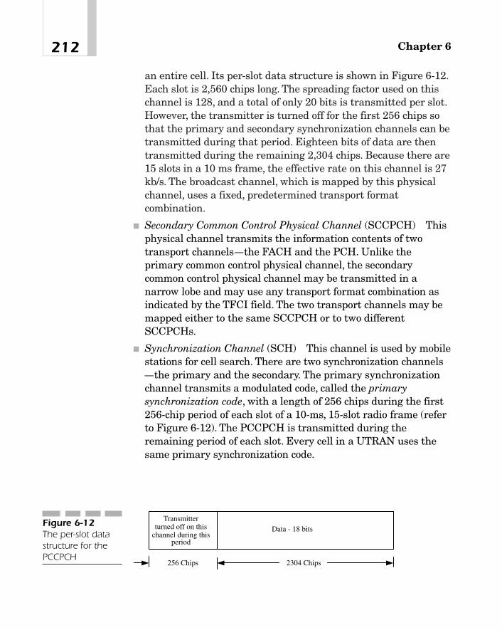
an entire cell. Its per-slot data structure is shown in Figure 6-12.Each slot is 2,560 chips long. The spreading factor used on thischannel is 128, and a total of only 20 bits is transmitted per slot.However, the transmitter is turned off for the first 256 chips sothat the primary and secondary synchronization channels can betransmitted during that period. Eighteen bits of data are thentransmitted during the remaining 2,304 chips. Because there are15 slots in a 10 ms frame, the effective rate on this channel is 27kb/s. The broadcast channel, which is mapped by this physicalchannel, uses a fixed, predetermined transport formatcombination.
� Secondary Common Control Physical Channel (SCCPCH) Thisphysical channel transmits the information contents of twotransport channels—the FACH and the PCH. Unlike theprimary common control physical channel, the secondarycommon control physical channel may be transmitted in anarrow lobe and may use any transport format combination asindicated by the TFCI field. The two transport channels may bemapped either to the same SCCPCH or to two differentSCCPCHs.
� Synchronization Channel (SCH) This channel is used by mobilestations for cell search. There are two synchronization channels—the primary and the secondary. The primary synchronizationchannel transmits a modulated code, called the primarysynchronization code, with a length of 256 chips during the first256-chip period of each slot of a 10-ms, 15-slot radio frame (referto Figure 6-12). The PCCPCH is transmitted during theremaining period of each slot. Every cell in a UTRAN uses thesame primary synchronization code.
Chapter 6212
256 Chips 2304 Chips
Data - 18 bitsTransmitter
turned off on thischannel during this
period
Figure 6-12The per-slot datastructure for thePCCPCH
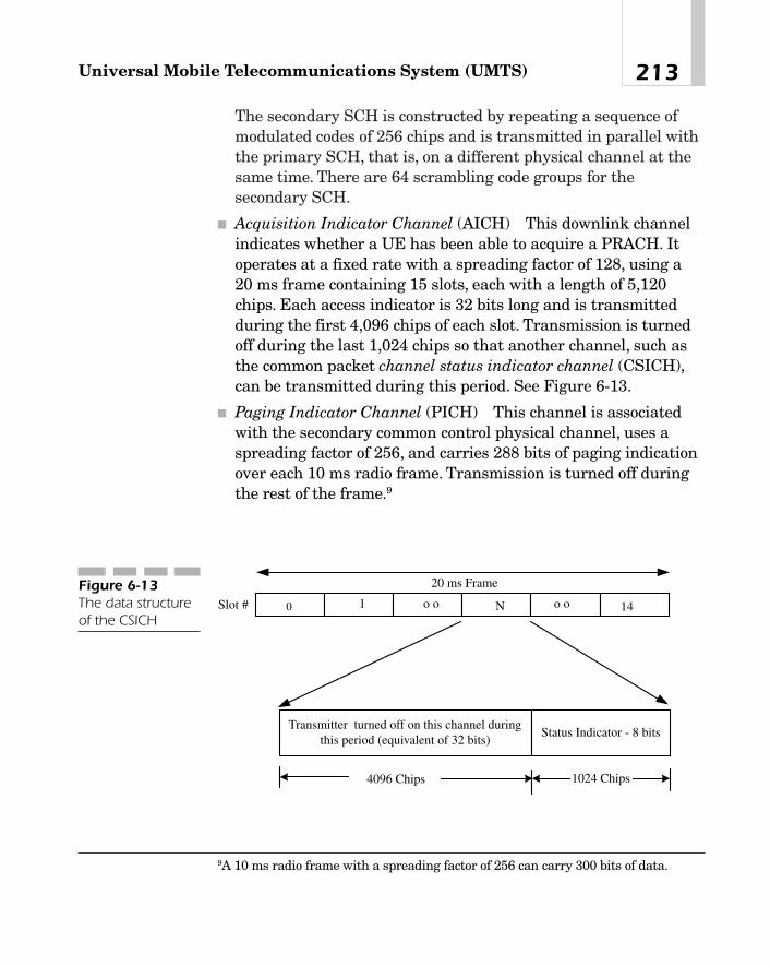
The secondary SCH is constructed by repeating a sequence ofmodulated codes of 256 chips and is transmitted in parallel withthe primary SCH, that is, on a different physical channel at thesame time. There are 64 scrambling code groups for thesecondary SCH.
� Acquisition Indicator Channel (AICH) This downlink channelindicates whether a UE has been able to acquire a PRACH. Itoperates at a fixed rate with a spreading factor of 128, using a20 ms frame containing 15 slots, each with a length of 5,120chips. Each access indicator is 32 bits long and is transmittedduring the first 4,096 chips of each slot. Transmission is turnedoff during the last 1,024 chips so that another channel, such asthe common packet channel status indicator channel (CSICH),can be transmitted during this period. See Figure 6-13.
� Paging Indicator Channel (PICH) This channel is associatedwith the secondary common control physical channel, uses aspreading factor of 256, and carries 288 bits of paging indicationover each 10 ms radio frame. Transmission is turned off duringthe rest of the frame.9
213Universal Mobile Telecommunications System (UMTS)
4096 Chips
Status Indicator - 8 bitsTransmitter turned off on this channel during
this period (equivalent of 32 bits)
0 1 o o N o o 14
20 ms Frame
Slot #
1024 Chips
Figure 6-13The data structureof the CSICH
9A 10 ms radio frame with a spreading factor of 256 can carry 300 bits of data.
� Common Packet Channel (CPCH) Status Indicator Channel(CSICH) As the name implies, this channel carries the CPCHstatus information. More specifically, the UTRAN uses it tonotify the user which slots are available, indicating the datarates supported on those channels. It operates at a fixed ratewith a spreading factor of 128. Its data structure is shown inFigure 6-13. This channel is deactivated during the first 4,096chips so that another channel, such as the acquisition indicatorchannel (AICH), the CPCH Access Preamble AcquisitionIndicator Channel (AP-AICH), or the collision detection/channelassignment indicator channel (CD/CA-ICH) can be activatedduring the same period.
� Physical Downlink Shared Channel (PDSCH) This channel,which maps a DSCH transport channel, is always associatedwith one or more downlink DPCH (that is, downlink dedicatedphysical channels). It consists of 10 ms frames, each containing15 slots. The spreading factors used range from 2 to 128.
Packet Mode Data
It is clear from the previous description that packet mode datafrom the user plane may be transmitted over a number of chan-nels. If the packets are short and infrequent, they may be trans-mitted over a RACH, CPCH, or FACH rather than a dedicatedchannel where the associated overhead may be unacceptably high.The RACH and CPCH are multiple-access channels and use theslotted Aloha scheme. If packets are long and relatively more fre-quent, a dedicated channel is established. In this case, after trans-mitting all packets that have arrived at the input, the channelmay be either released immediately or held only for a short periodthereafter. If there are any new packets during this period, theyare transmitted; otherwise, the channel is released at the end ofthat period.
Chapter 6214
TEAMFLY
Team-Fly®

Mapping of Transport Channels to Physical Channels
As we indicated in the last section, the physical layer, on receivingthe data over a transport channel, transmits it over a radio frameusing a particular physical channel. In other words, transport chan-nels are mapped to specific physical channels. This mapping is sum-marized in Figure 6-14.
Physical Layer Procedures
The standards documents specify procedures for synchronization,power control, accessing common channels, transmit diversity, andthe creation of idle periods in the downlink. In this section, we willpresent a brief description of some of these procedures.
215Universal Mobile Telecommunications System (UMTS)
DCH DPDCHDPCCH
BCH
PCH
FACH
RACH
CPCH
DSCH
PCCPCH
SCCPCH
PRACH
PCPCH
PDSCHSCHAICHAP-AICHPICHCSICHCD/CA-ICH
CPICH
Transport Channels Physical ChannelsFigure 6-14Mapping oftransport channelsinto physicalchannels
Synchronization Procedures Synchronization proceduresinclude the cell search mechanism and synchronization on the ded-icated channels—the common physical channels as well as the ded-icated physical control and data channels.
Cell Search Procedure By cell search, we mean searching for a cell,identifying the downlink scrambling code, achieving the frame syn-chronization, and finding the exact primary scrambling code used inthe desired cell. The procedure is outlined in the following steps:1. Because the primary synchronization code is the same for all
cells in a system and is transmitted in every slot of the primarysynchronization subchannel, the slot boundaries can bedetermined by passing the received signal through a filter that ismatched to the primary synchronization code and observing thepeaks at its output.
2. Notice that it is not possible to identify the frame boundary instep 1.10 To do this, the received signal is correlated with each ofthe 64 secondary codes, and the output of the correlator iscompared during each slot. The code for which the output ismaximum is the desired secondary synchronization code.Similarly, the sequence of 15 consecutive slots over which thecorrelator output is maximum provides the framesynchronization.
3. The last step is concerned with the determination of the primaryscrambling code. Because the common pilot channel is scrambledwith the primary scrambling code, the latter can be determinedby correlating the received signal over this channel with allcodes within the code group determined in step 2. After havingfound the scrambling code, it is now possible to detect theprimary common control physical channel that maps thebroadcast channel.
Chapter 6216
10At this point, only slot boundaries have been found, but we do not know yet whichslot belongs to which frame.

Synchronization on the Physical Channels Once frame synchroniza-tion has been achieved during the course of the cell search proce-dure, the radio frame timing of all common physical channels isknown. Thereafter, layer 1 periodically monitors the radio framesand reports the synchronization status to the higher layers.
The status is reported to the higher layers using the following rules:
1. During the first 160 ms following the establishment of adownlink dedicated channel, the signal quality of the DPCCH ismeasured over the last 40 ms. If this measured signal is betterthan a specific threshold Qin, the channel is reported to be insync. At the end of this 160 ms window, go to step 2.
2. Measure the signal quality of the DPCCH over a 160-ms period.Also check transport blocks with attached CRCs. If the signal isless than a threshold Qout, or if the last 20 transport blocks aswell as all transport blocks received in the previous 160 ms haveincorrect CRCs, declare the channel as out of sync. If, on theother hand, the quality exceeds Qin, and at least one transportblock received in the current frame has a correct CRC, thechannel is taken to be in sync. Similarly, if the signal exceeds Qin
but no transport blocks or no transport blocks with a CRC arereceived, the status is taken to be in sync.
Setting Up a Radio Link When setting up a radio link, there are twocases to consider depending on whether or not there already existsa radio link for the UE:
� To establish a radio link when there are none initially, theUTRAN starts transmitting on a downlink DPCCH. If there isany user data to send, it may also start transmitting that dataon a downlink DPCCH.11
The UE monitors the downlink DPCCH and first establishesframe synchronization using a PCCPCH. Thereupon, it can begin
217Universal Mobile Telecommunications System (UMTS)
11Recall that the downlink DPCCH and the downlink DPDCH are time-division mul-tiplexed.

to transmit on the uplink DPCCH either immediately or, ifnecessary, after a delay of a specified activation time followingthe successful establishment of the downlink channel.Transmission on the uplink DPDCH can start only after the endof the power control preamble.
The base transceiver station monitors the uplink DPCCH andestablishes chip and frame synchronization on that channel.Once the higher layers in the UTRAN have determined that thelink is in sync, the radio link is considered established.
� To set up a radio link when there are other radio links alreadyestablished, the UTRAN begins to transmit on a new downlinkDPCCH and, if necessary, on a new downlink DPDCH withappropriate frame timing.
The UE monitors the new downlink DPCCH, establishes framesynchronization on this channel, begins to transmit on an uplinkDPCCH, and, if necessary, on an uplink DPDCH as well.
The base transceiver station monitors the uplink DPCCH andestablishes chip and frame synchronization on that channel.Once the higher layers in the UTRAN have determined that thelink is in sync, the new radio link is considered established.
It is possible that the receive timing of a downlink DPCH maydrift significantly over time so that the time difference betweendownlink and uplink frames exceeds the permissible value.When this is the case, the physical layer reports the event tohigher layers so that the network can be requested to adjust itstiming.
Power Control As we mentioned, power control is an importantfeature of a CDMA system. Its objective is to ensure a satisfactorysignal-to-interference ratio at the receiver for all links in the sys-tem. In UMTS, different power control procedures are used foruplink and downlink physical channels. Because our goal is toacquaint the reader with the general concept of the power controlin UMTS, we will briefly describe only some of these procedures[12]. First, however, definitions of a few terms are in order.
Chapter 6218

Open Loop Power Control This is a process by which theUE sets its transmitter power output to any specific level.The open loop power control tolerance is �9 dB undernormal conditions and �12 dB under extreme conditions.
Inner Loop Power Control in the Downlink Thisprocedure enables a base station to adjust its transmitpower in response to TPC commands from the UE. Power isadjusted using a step size of 0.5 or 1 dB. The objective hereis to maintain a satisfactory signal-to-interference ratio at aUE using as little base station transmitter signal power aspossible.
Inner Loop Power Control in the Uplink This procedureis used by the UE to adjust its transmit power in responseto a TPC command from a base station. With each TPCcommand, the UE transmit power is adjusted in steps of 1,2, or 3 dB in the slot immediately following the decoding ofTPC commands.
A TPC command may be either 0 or 1. If it is 0, it means that thetransmitter power has to be decreased. If it is 1, the transmitterpower is to be increased.
Uplink Inner Loop Power Control Procedure on Dedicated Physical Chan-nels The dedicated physical channels use the uplink inner looppower control. Briefly, the procedure is as follows. The UE startstransmitting on the uplink DPCCH at a power level that is initiallyset by the higher layers. Serving cells measure the received SIR andcompare it with a target threshold. If the measured SIR exceeds thethreshold, the UTRAN sends a TPC command 0, indicating that themobile station should decrease its power level using a step size of 1or 2 dB as specified by the higher layers. If the measured SIR is lessthan the threshold, TPC command 1 is transmitted, requiring themobile to increase its power level. If both data and control channelsare active at the same time, the power level of both uplink channelsis changed simultaneously by the same amount. For a DPCCH, thischange should be affected at the beginning of the uplink DPCCHpilot field immediately following the TPC command on the downlink
219Universal Mobile Telecommunications System (UMTS)

channel. This is shown in Figure 6-15. Notice the timing offsetbetween the downlink DPCH and the uplink DPCCH. It is alsoworth mentioning that the TPC command on the uplink starts 512chips after the end of the pilot field on the downlink channel.
When a mobile station is being served by a single cell and is not ina soft handoff state, it receives only one TPC command in each slot.Because there are 15 slots in a radio frame and each frame is 10 mslong, it may receive 1,500 TPC commands per second.
However, if the mobile is in a soft handoff state, more than oneTPC command may be received in each slot of a radio frame fromcells in an active set that participate in the handoff process. Thephysical layer parses these commands, and if it finds all TPC com-mands to be 1, it increases the transmitter power by the selectedstep size. Similarly, if all commands are 0, the power is decreased bythe same amount. Otherwise, if the commands are all random anduncorrelated, they are interpreted based on a probabilistic model[12]. The same procedure is used to adjust the power level during theuplink DPCCH power control preamble.12
The procedure that we have just described adjusts the power levelin accordance with the TPC commands received during each slot,
Chapter 6220
Pilot PilotData 1 TPC TFCI Data 2 Data TFCI
Slot N+1
TPC
Slot NSlot N-1
DownlinkDPCH
Slot NSlot N-1 Slot N+1
UplinkDPCCH
PilotTFCI TPC Pilot TFCI TPC
Timing offsetbetween UL andDL - 1024 chips
UTRANmeasures this
signal
512 chips
UTRAN sends thisTPC command
Pilot
UE gets this TPCcommand and sets
uplink DPCH powerat start of this field
DPDCH DPCCH DPDCH DPCCH
Figure 6-15The sequence ofevents and theirtiming during theuplink powercontrol
12The transmission on a DPDCH starts only after the end of this preamble.

using a step size of 1 or 2 dB. This is referred to in the standards doc-ument as Algorithm 1. Using a slight variation of this algorithm, wecan emulate a smaller step size and thus effect a finer adjustment.This is called Algorithm 2, which is briefly described here. Assumethat the mobile is being served by a single cell and is not goingthrough any handoff process. For each set of five slots aligned to theframe boundaries, no action is taken on those commands that werereceived in the first four slots. During the fifth slot, the receiverdetermines if the TPC commands in all of these five slots are thesame. If they are, the power level is increased or decreased by theprevious step size, depending on whether they are all 1 or 0. Other-wise, the commands are ignored. Because the power level is nowbeing changed by the same amount every five slots, the net result isthe equivalent of a smaller step size.
The procedure to emulate a smaller step size when the mobile isundergoing a handoff process is similar.
Downlink Inner Loop Power Control on DPCCH and DPDCH The oper-ation of the downlink inner loop power control is quite similar.Assuming that the mobile is being served by a single cell and is notgoing through a handoff process, the UE measures the SIR on thedownlink physical channels and compares it with a desired targetvalue. If the measured SIR is less, the UE sets the TPC command to1 in the next available TPC field of the uplink DPCCH. The UTRANresponds by increasing the power of the downlink DPCH at thebeginning of the next pilot field on that channel following the TPCcommand on the uplink.
If the measured SIR is more than the desired value, a TPC com-mand 0 is sent in the next available TPC field of the uplinkDPCCH, thus requesting a reduced power level. In response, theUTRAN decreases the power level of the downlink DPCH at thebeginning of the next pilot field on that channel following the TPCcommand on the uplink. The downlink power control timing isshown in Figure 6-16.
Depending on the downlink power control mode, the UE may sendeither a unique TPC command in each slot or the same commandover three slots while making sure that a new command appears atthe beginning of a radio frame. On receiving a TPC command, the
221Universal Mobile Telecommunications System (UMTS)
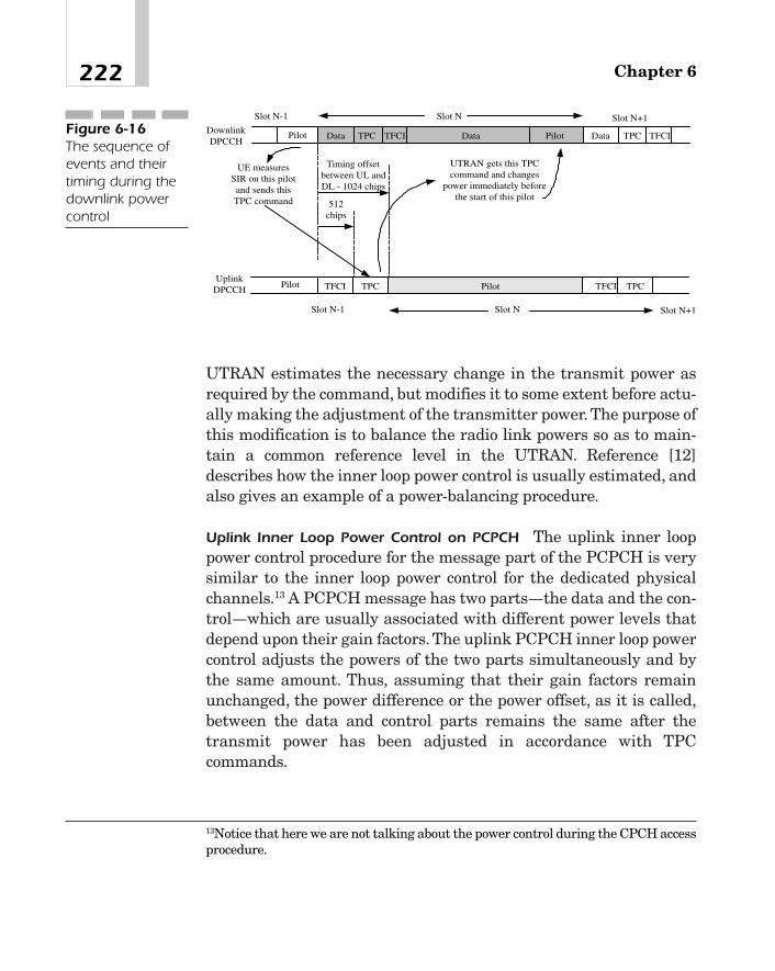
UTRAN estimates the necessary change in the transmit power asrequired by the command, but modifies it to some extent before actu-ally making the adjustment of the transmitter power. The purpose ofthis modification is to balance the radio link powers so as to main-tain a common reference level in the UTRAN. Reference [12]describes how the inner loop power control is usually estimated, andalso gives an example of a power-balancing procedure.
Uplink Inner Loop Power Control on PCPCH The uplink inner looppower control procedure for the message part of the PCPCH is verysimilar to the inner loop power control for the dedicated physicalchannels.13 A PCPCH message has two parts—the data and the con-trol—which are usually associated with different power levels thatdepend upon their gain factors. The uplink PCPCH inner loop powercontrol adjusts the powers of the two parts simultaneously and bythe same amount. Thus, assuming that their gain factors remainunchanged, the power difference or the power offset, as it is called,between the data and control parts remains the same after thetransmit power has been adjusted in accordance with TPCcommands.
Chapter 6222
Pilot PilotData TPC TFCI Data Data TFCI
Slot N+1
TPC
Slot NSlot N-1
DownlinkDPCCH
Slot NSlot N-1 Slot N+1
UplinkDPCCH
Pilot TFCI TPC Pilot TFCI TPC
Timing offsetbetween UL andDL - 1024 chips
UE measuresSIR on this pilotand sends thisTPC command 512
chips
UTRAN gets this TPCcommand and changes
power immediately beforethe start of this pilot
Figure 6-16The sequence ofevents and theirtiming during thedownlink powercontrol
13Notice that here we are not talking about the power control during the CPCH accessprocedure.

The UTRAN measures the SIR on the received PCPCH and com-pares it with the desired SIR objective. If the measured SIR is less,the network sends a TPC command 1, requesting that the power beincreased. If it is more, the network sends a TPC command 0, indi-cating that the power should be decreased. The UE may process theTPC commands and adjust the uplink transmit power in steps of 1or 2 dB using either Algorithm 1 or Algorithm 2 that was describedearlier.
Random Access Procedure Random access procedures are usedto transmit data (that is, the signaling information and/or user data)on the two uplink physical channels: the PRACH and the PCPCH.The procedures are initiated when the physical layer receives a ser-vice request from the MAC layer. These procedures, which aredescribed in great detail in the standards documents, are similar forthe two physical channels. We will illustrate them by providing abrief description of the access mechanism on the PRACH only.
Random Physical Access Channel There are 12 RACH subchannels,each containing five access slots. The UE may select any one of theseslots on the available RACH subchannels within an access serviceclass and commence transmission. The procedure uses a number ofsystem parameters including, among others, preamble scramblingcode, available RACH subchannels for each access service class, themaximum number of preamble retransmissions, and the initial pre-amble power. The UE receives these parameters from the radioresource control layer of the UTRA. A brief description of the proce-dure is presented in Figure 6-17.
Spreading and Modulation
In UMTS, the signal is spread in two steps. First, all physical chan-nels with the exception of the downlink synchronization channelsare spread by unique channelization codes so that they can be sepa-rated at the receiver. The spreading factor is defined as the numberof chip periods into which each incoming symbol is spread. The
223Universal Mobile Telecommunications System (UMTS)
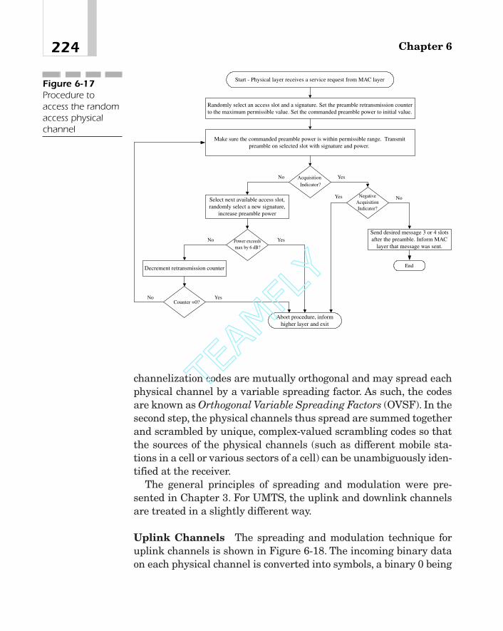
channelization codes are mutually orthogonal and may spread eachphysical channel by a variable spreading factor. As such, the codesare known as Orthogonal Variable Spreading Factors (OVSF). In thesecond step, the physical channels thus spread are summed togetherand scrambled by unique, complex-valued scrambling codes so thatthe sources of the physical channels (such as different mobile sta-tions in a cell or various sectors of a cell) can be unambiguously iden-tified at the receiver.
The general principles of spreading and modulation were pre-sented in Chapter 3. For UMTS, the uplink and downlink channelsare treated in a slightly different way.
Uplink Channels The spreading and modulation technique foruplink channels is shown in Figure 6-18. The incoming binary dataon each physical channel is converted into symbols, a binary 0 being
Chapter 6224
Start - Physical layer receives a service request from MAC layer
Select next available access slot,randomly select a new signature,
increase preamble power
Randomly select an access slot and a signature. Set the preamble retransmission counterto the maximum permissible value. Set the commanded preamble power to initial value.
AcquisitionIndicator?
Power exceedsmax by 6 dB?
Abort procedure, informhigher layer and exit
Decrement retransmission counter
NegativeAcquisitionIndicator?
Send desired message 3 or 4 slotsafter the preamble. Inform MAC
layer that message was sent.
Make sure the commanded preamble power is within permissible range. Transmitpreamble on selected slot with signature and power.
Counter =0?
YesNo
Yes No
YesNo
No Yes
End
Figure 6-17Procedure toaccess the randomaccess physicalchannel
TEAMFLY
Team-Fly®

represented by �1 and binary 1 as �1.14 Now assume that a num-ber of these channels have to be transmitted using a single CDMAcarrier. As an example, a mobile station may have a number ofuplink DPDCHs as well as a DPCCH. In this case, the channels aredivided into two sets—say, channels A, B, and so on in one set, andchannels X, Y, and so on, along with the DPCCH, in another. Thephysical channels are split this way so that one set of channels mod-ulates an in-phase (that is, I) carrier and the other set a quadrature(that is, Q) carrier.15
Continuing with Figure 6-18, each of the physical channels isspread by a unique OVSF code. The spreading factor is 256 for a con-trol channel and varies from 4 to 256 for a data channel. Because dif-ferent channels are usually transmitted at different relative powerlevels, the spread symbols are multiplied with appropriate gain fac-tors and summed together. The gain factors vary from 0 to 1 in stepsof 1/15. Because the resulting real-valued symbol sequences, indicated
225Universal Mobile Telecommunications System (UMTS)
PhysicalChannel A
I
X X
X X
ooo
11C
12C
11G
12G
PhysicalChannel B
PhysicalChannel X X X
X X
ooo
21C
22C
21G
22G
PhysicalChannel Y
X
Q
ComplexScrambling
Code
To Modulator+
090
�
�
Figure 6-18Spreading multiplephysical channelsfrom a mobilestation
14In other words, we are going to use binary phase shift keying.15Each set modulates the carrier using BPSK. The net result, of course, is QPSK.

as I and Q in the figure, are to be scrambled by a complex scramblingcode, the I and Q sequences are transformed into a complex sequenceby first advancing the phase of Q by 90 degrees and then adding it toI.16 The output of the scrambler is separated into real and imaginaryparts, and applied to the modulator, as shown in Figure 6-5.
Because the symbols from the second channel set are shifted by 90degrees before adding them to the symbols of the first set, the effec-tive modulation is QPSK with the constellation of Figure 6-19.
Downlink Channels The spreading of downlink channels isslightly different, as shown in Figure 6-20. Incoming symbols on alldownlink channels except AICH may be �1, -1 or 0. Symbol 0 cor-responds to the situation when the transmission is to be discontin-ued. The incoming data on each physical channel, with the exceptionof a synchronization channel, is converted into parallel form and sep-arated into two streams, one with the odd bits and the other withthe even bits. Each of these streams is spread by a channel-specific,orthogonal spreading code shown as C1 in this figure. The spreadingfactor is 256 for common downlink physical channels and variesfrom 4 to 512 for a downlink DPCH.
The I and Q channels are added in quadrature, scrambled by thecell-specific downlink scrambling code Sm, and multiplied by the gainfactor G1. The synchronization channel, on the other hand, is simply
Chapter 6226
16In other words, I and Q are added in quadrature.
Channel Set 1- binary 0
Channel Set 1- binary 1
Channel Set 2- binary 0
Channel Set 2- binary 1
Figure 6-19The signalconstellation inQPSK modulationused in UMTS

multiplied by gain Gsync. The complex-valued outputs from all chan-nels after the gain multiplication are added, separated into real andimaginary parts, and passed to the modulator.
Channelization Codes The channelization codes are mutuallyorthogonal and are obtained from an Nth order, orthogonal Walsh,or Hadamard matrix:
where each hij is either �1 or �1. This matrix is called orthogonalbecause the inner product of any two different rows is 0:
Thus, the entries of each row of such a matrix can be used as achannelization code. Before modulating with the channelizationcode, however, the incoming binary data is first subjected to a leveltransformation whereby a 0 is converted to �1 and a binary 1 to �1.
Orthogonal Hadamard matrices can be generated recursively asdiscussed in Chapter 3 when their dimension N is given by N � 2n
with n as an integer. They can also be represented in the form of atree. For example, in Figure 6-21, the entries of matrices H1, H2, andH4 are shown alongside the branches of a tree. Notice that matrix H4
corresponds to codes associated with branches emanating fromnodes C1 and C2, rows 1 and 3 representing codes at C1, and rows 2and 4 at C2.
aN�1
k�0hikhjk � 0 for i j
HN � 3hij 4 ,i,j � 0,1,2, p , N � 1
227Universal Mobile Telecommunications System (UMTS)
PhysicalChannel 1
IX
X
X
X
oo
1C
mS 1G
X
syncG
QTo Modulator
S/P
900
Other Similar
Channels
Sync Channel
Real Part
Imaginary
�
�
Figure 6-20Spreading ofdownlink channels

Scrambling Codes A scrambler maps an incoming data sequenceinto a different sequence such that if the input is periodic, the out-put is also periodic with a period that is usually many times theinput period. Scramblers are built using a series of shift registerswhere certain outputs are added module 2 and then fed back to theinput of the register array.
The theory of PN and scrambling codes was presented in Chapter3. For the purpose of this chapter, it is sufficient to point out that thefeedback path in a shift register array may be represented by a poly-nomial, say, f(x).17 It can then be shown that the period of the outputsequence from the scrambler is the smallest integer p such that f(x)divides xp � 1 using, of course, modulo 2 addition when performingthe polynomial division. If there are m registers in the array, f(x) isof degree m, and the maximum possible period of the scrambler out-put is 2m � 1. In this case, we say that the shift register sequence hasa maximum length. However, to achieve this length, it is necessarythat f(x) be irreducible; that is, it should be divisible only by itself andby 1.18
Chapter 6228
C0 0 1, ( )=
C1 0 11, ( , )=
C1 1 1, ( , −1)=
C2 0 1111, ( , , , )=
C2 1 11 1 1, ( , , , )= − −
C2 2 1 11 1, ( , , , )= − −
C2 3 1 1 11, ( , , , )= − −
AB
C1
C2
SF = =2 10
SF = =2 21
SF = =2 42
SF = =2 83
Figure 6-21Orthogonalchannelizationcodes arranged inthe form of a tree
17f(x) is also known as the characteristic polynomial.18In the literature, this polynomial is sometimes referred to as a primitive polynomialover a Galois field GF(2m). To understand it, suppose that we want to construct theGalois field GF(2m) that has 2m elements where m is an integer. If we use arithmetic
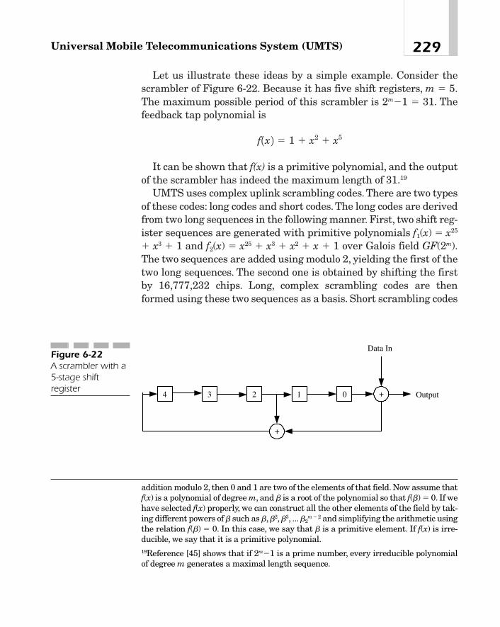
Let us illustrate these ideas by a simple example. Consider thescrambler of Figure 6-22. Because it has five shift registers, m � 5.The maximum possible period of this scrambler is 2m�1 � 31. Thefeedback tap polynomial is
It can be shown that f(x) is a primitive polynomial, and the outputof the scrambler has indeed the maximum length of 31.19
UMTS uses complex uplink scrambling codes. There are two typesof these codes: long codes and short codes. The long codes are derivedfrom two long sequences in the following manner. First, two shift reg-ister sequences are generated with primitive polynomials f1(x) � x25
� x3 � 1 and f2(x) � x25 � x3 � x2 � x � 1 over Galois field GF(2m).The two sequences are added using modulo 2, yielding the first of thetwo long sequences. The second one is obtained by shifting the firstby 16,777,232 chips. Long, complex scrambling codes are thenformed using these two sequences as a basis. Short scrambling codes
f1x 2 � 1 � x2 � x5
229Universal Mobile Telecommunications System (UMTS)
addition modulo 2, then 0 and 1 are two of the elements of that field. Now assume thatf(x) is a polynomial of degree m, and b is a root of the polynomial so that f(b) � 0. If wehave selected f(x) properly, we can construct all the other elements of the field by tak-ing different powers of b such as b,b2,b3, ...b2
m � 2 and simplifying the arithmetic usingthe relation f(b) � 0. In this case, we say that b is a primitive element. If f(x) is irre-ducible, we say that it is a primitive polynomial.19Reference [45] shows that if 2m�1 is a prime number, every irreducible polynomialof degree m generates a maximal length sequence.
Data In
04 3 2 Output1
+
+
Figure 6-22A scrambler with a5-stage shiftregister

are generated from three sequences, each using an array of 8 regis-ters and a feedback polynomial of degree 8. For details, see Chapter3 and Reference [11].
Uplink scrambling codes may be either long or short. The longcodes have a length of 38,400 chips (that is, 10 ms), whereas shortcodes are only 256 chips long. The use of short codes on an uplinkchannel requires advanced multiuser detection techniques at thebase station.
Downlink scrambling codes are also complex valued and, like thelong uplink scrambling codes, are generated using two constituentsequences, which are derived from two shift register arrays withprimitive polynomials: f1(x) � x18 � x7 � 1 and f2(x) � x18 � x10 � x7 �
x5 � 1 over GF(2m). There are a total of 218 � 1 of these codes. How-ever, only 8,192 are used on downlinks. They are divided into 512groups, each containing one primary scrambling code and 15 sec-ondary scrambling codes. Each code is of length 38,400 chips.
Physical Layer Measurements
From time to time, the user equipment and UTRAN are required toperform signal measurements and, if necessary, report the results tohigher layers.These measurements are required for a number of rea-sons. For example, the UTRAN may use them to determine if it isnecessary to handover a mobile to another base station using thesame carrier, to another base station using a different carrier, toanother system (for example, a GSM network), or to another serviceprovider, if necessary. Measurements are performed periodically, oron demand, or may be triggered by some events (for example, thecurrent CCPCH is no longer the best one). They are evaluated andfiltered at different layers before they are reported to the higher lay-ers. These measurements are done during idle slots inserted in aradio frame for this purpose.The mechanism by which these inactiveslots are built in a radio frame so that the UE can perform thesemeasurements is called the compressed mode.
Measurements may be divided into a few types:
� Measurements on downlink physical channels. Thesemeasurements may involve a single W-CDMA frequency,
Chapter 6230

different W-CDMA frequencies (such as when a UE is near theboundary of two W-CDMA systems), or a W-CDMA frequencyand the operating frequency of another system such as GSM.
� Traffic volume measurements on uplink channels
� UE transmit power and received signal level
� Measurements of quality of service (QoS) parameters such asblock error rates and delay variations
Some of the parameters that are measured by the UE are listed inthe following list. For a more detailed description of these parame-ters, see [14].
� Time difference between the system frame number (SFN) of thetarget neighboring cell and connection frame number (CFN) inthe UE. It is given in terms of chips for the FDD mode andframe numbers for the TDD mode.
� Difference between the timing of a given UTRA and the timingof a GSM cell.
� Ec/N0 for the common pilot channel (CPICH), where Ec is thereceived energy per chip and N0 the noise power density.
� SIR for CPICH.
� Received signal code power on the PCCPCH after despreading.
� Interference with the received signal on the common pilotchannel after despreading.
� Received signal strength indicator (RSSI), which is the widebandsignal strength measured in the desired bandwidth.
� Transport channel block error rate.
� The UE transmitter power at the antenna connector.
� Time difference between an uplink frame and the firstsignificant path of a downlink frame on a dedicated physicalchannel. This measurement is valid only for the FDD mode.
� Time difference in the system frame numbers between a specificcell and a target cell on CPICH and PCCPCH.
The following is a partial list of the parameters measured by aUTRAN:
231Universal Mobile Telecommunications System (UMTS)

� Received power over an uplink channel. For a diversity receiver,this is a linear average on the diversity branches.
� The transmitted power on a downlink carrier with respect to themaximum power possible on that carrier.
� Transport channel block error rate (BLER) and BER.
� The physical channel bit error rate.
� Receive timing deviation. Valid only for TDD mode, this is thepropagation delay of an uplink signal.
� Received signal code power on a dedicated physical channel or aPRACH after despreading. Valid only for TDD mode.
� Round-trip delay between the start of a downlink frame and thebeginning of a corresponding uplink frame.
� Frequency offsets between two nodes.
� SIR. As defined in the standards documents, it is actually thesignal-to-interference ratio multiplied by the spreading factor.Measurement is done on the dedicated physical control channelin the FDD mode and dedicated physical channel in the TDDmode.
� Propagation delay in accessing the PRACH or a PCPCH.
MAC Layer Protocol
Overview
The MAC layer, as the name implies, determines how different typesof information coming from the higher layers over different logicalchannels should be transmitted over a physical channel on a radioframe (that is, the medium), and controls the timing of those trans-missions [7], [15]. It provides the following services to the upper lay-ers: data transfer, reallocation of radio resources and redefinition ofMAC parameters, and measurement of the traffic volume and signalquality, and reporting the results to the RRC layer.
Chapter 6232

The MAC layer interacts with the RLC sublayer over a numberof logical channels. Data flows on each logical channel are associ-ated with a certain priority based on the attributes of the radiobearer service and the RLC buffer status. For example, if a partic-ular UE is running two applications simultaneously, say, voice anda file transfer in the background, the RRC sublayer may assign adifferent priority to each of the two applications. Similarly, multipleUEs may be assigned relative priorities as well. To meet these pri-ority requirements, the MAC layer may use some scheduling algo-rithms and map, say, high-priority data to a high-bit-rate transportformat and low-priority data to a low-bit-rate transport format.Thus, the responsibility of the MAC layer is to map each logicalchannel onto a transport channel, selecting, on the basis of theassociated priorities, an appropriate transport format within aTransport Format Combination (TFC) set that is assigned by theRRC layer. When multiple users access a RACH, the MAC layerinforms the physical layer of the RACH resources assigned to eachuser (such as access slots, channelization codes, back-off parame-ters, and so on). Other functions of the MAC sublayer include thefollowing:
� Multiplexing higher layer protocol data units (PDUs) ontotransport blocks and delivering them to the physical layer on acommon transport channel or a dedicated channel
� Demultiplexing the transport blocks received from the physicallayer into higher-layer PDUs and presenting them to the higherlayer
� Measuring traffic volumes on a logical channel and reporting theinformation to the RRC layer so that it can control the admissionof new users and provide required QoS
� Ciphering of data for transparent mode operation of the RRClayer
The MAC layer supports only unacknowledged data transfer with-out any segmentation or reassembly. It interfaces the RLC layer overlogical channels and the physical layer over transport channels. Toavoid repetition, it is sufficient to say that the various logicalchannels are similar in concept to the transport channels, which
233Universal Mobile Telecommunications System (UMTS)

were discussed earlier. The MAC layer maps them into transportchannels as shown in Figure 6-23.
MAC Procedures
The MAC layer follows a set of procedures that enables differentUEs to access a RACH or a CPCH. We will describe only one of them,namely the one that controls transmissions on a RACH.
Transmission Control on a RACH For the purpose of accessingthis channel, the access slots and preamble signatures (or the timeslots and channelization codes in a TDD system), which are referredto in the standards documents as RACH resources, are assigned aset of relative priorities. Based on these priorities, the resources canbe divided into a number of Access Service Classes, each using a cer-tain partition of the RACH slots with a given transmission proba-bility (persistence value).
The medium access control procedure for a RACH is briefly thefollowing:
1. The MAC layer receives from the RRC layer RACHtransmission control parameters such as available access serviceclasses, backoff time intervals after which a UE can resume
Chapter 6234
Broadcast Control Channel (BCCH)
PCH
BCH or FACH
RACH or FACH
Transport ChannelsLogical Channels
Paging Control Channel (PCH)
Common Control Channel (CCCH)
Dedicated Control Channel (DCCH)
Dedicated Traffic Channel (DTCH)
CPCH (FDD mode only), FAUSCH, RACH,FACH, USCH (TDD mode only), DSCH or DCH
CPCH (FDD mode only), RACH, FACH, USCH,DSCH, or DCH
Shared Channel Control Channel (SHCH) (TDD only) RACH, FACH, USCH (TDD only), or DSCH
Common Traffic Channel (CTCH) FACH
Figure 6-23Mapping of logicalchannels intotransport channels
TEAMFLY
Team-Fly®

transmission following a negative acknowledgment on theacquisition indication channel, and so on.
2. When the MAC layer receives from the higher layer a servicedata unit that has to be transmitted on the RACH, it selects anavailable access service class and initializes a preambletransmission counter to 0.
3. The preamble counter is incremented by 1. If its value is lessthan or equal to the maximum permissible value, go to step 4.Otherwise, terminate the access procedure and report errorconditions to the higher layers.
4. The MAC layer selects a random number in the range of 0 to 1.If this number is greater than the transmission probabilityassociated with the selected access service class, the MAC layershall wait for the next transmission timing interval and repeatstep 4. Otherwise, send an access request primitive to thephysical layer and go to step 5.
5. If there is no acknowledgment from the physical layer, wait forthe next transmission timing interval and go to step 3.
If the MAC layer receives a NACK (that is, a negative acknowl-edgment) on the Acquisition Indication Channel (AICH), wait untilthe next transmission timing interval. Then select a random backoffinterval, set a backoff timer to this value, start the timer, wait untilthis backoff timer has expired, and go to step 3.
If, on the other hand, the MAC layer has received an ACK (that is,a positive acknowledgment), send the higher-layer data to the phys-ical layer via a data request primitive.
Traffic Volume Measurement Before configuring a new radiobearer, the Radio Resource Control layer may require information onthe traffic volume carried by each transport channel. The RRC indi-cates to the MAC layer, via a Measure-REQ primitive, which trafficparameters—buffer occupancy, its average value, and its variance oneach radio bearer—should be reported, whether the report should besent periodically, and, if so, at what interval, or whether the reportshould be generated only when certain criteria are met (for example,
235Universal Mobile Telecommunications System (UMTS)

the amount of data to be transmitted on a transport channel is out-side a range set by the RRC). Similarly, the RLC may also notify theMAC layer about the amount of data queued in its buffer. If the modeis periodic, the MAC layer gathers the requested information duringeach transmission timing interval and sends it to RRC at prescribedintervals. Otherwise, it compares the amount of traffic on a trans-port channel with the thresholds specified by the RRC, and reportsonly the result of this comparison.
MAC Layer Data Formats
On receiving an upper-layer PDU, the MAC layer adds a header andpasses the resulting PDU to the physical layer. The MAC PDUs,arriving at the physical layer during any transmission timing inter-val, are transmitted in the order in which they arrive. Similarly, theMAC PDUs corresponding to a given logical channel are multiplexedin the same order in which they originate at the higher layers.
The general format of the MAC PDU is presented in Figure 6-24.There are four fields in the header. The first field called the TargetChannel Type Field (TCTF) indicates the logical channel and may be1, 2, 3, 4, 5, or 8 bits long depending upon the associated transportchannel and the mode (that is, FDD or TDD). For example, on aRACH in the FDD mode, this field is 00 for a common control chan-nel and 01 for a dedicated control or traffic channel.
Chapter 6236
MAC PDUMAC SDUTCTF
UE IDType
UE ID C/T
To the Physical Layer
Higher Layer PDUFigure 6-24The MAC PDUformat

On the other hand, on a RACH in the TDD mode, that field is 00for a common control channel and 0100 for a dedicated control ortraffic channel.
Because multiple users may be transmitting on a common trans-port channel, it is necessary to separate them using UE Identifica-tion numbers. There are two types of UE IDs—the UTRAN RadioNetwork Temporary ID (U-RNTI) and the Cellular Radio NetworkTemporary ID (C-RNTI). They are indicated by the 2-bit UE ID Typefield. The UE IDs are 32 bits long for U-RNTI and 16 bits for C-RNTI.
The C/T field is four bits long and identifies the logical channel ina MAC PDU when multiple logical channels are multiplexed on thesame transport channel.
Depending upon the logical and transport channels, some or all ofthe four fields of the MAC PDU header may be missing. For example,when a dedicated traffic or control channel is mapped to a dedicatedchannel, the entire header is omitted. On the other hand, when theyare mapped to a RACH or a FACH, all four fields of the header areincluded.
Radio Link Control Protocol
RLC Functions
As shown in Figure 6-3, the RLC layer interfaces the RRC, PDCP,and BMC layers on one side and the MAC layer on the other. Itsmain functions are
� Data transfer
� Segmentation and reassembly
� Error detection and correction
� Flow control
� Ciphering for the purpose of providing security
237Universal Mobile Telecommunications System (UMTS)
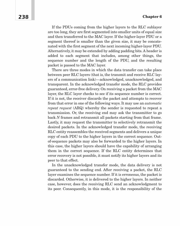
If the PDUs coming from the higher layers to the RLC sublayerare too long, they are first segmented into smaller units of equal sizeand then transferred to the MAC layer. If the higher-layer PDU or asegment thereof is smaller than the given size, it may be concate-nated with the first segment of the next incoming higher-layer PDU.Alternatively, it may be extended by adding padding bits. A header isadded to each segment that includes, among other things, thesequence number and the length of the PDU, and the resultingpacket is passed to the MAC layer.
There are three modes in which the data transfer can take placebetween peer RLC layers (that is, the transmit and receive RLC lay-ers of a communication link)—acknowledged, unacknowledged, andtransparent. In the acknowledged transfer mode, the RLC providesguaranteed, error-free delivery. On receiving a packet from the MAClayer, the RLC layer checks to see if its sequence number is correct.If it is not, the receiver discards the packet and attempts to recoverfrom that error in one of the following ways. It may use an automaticrepeat request (ARQ) whereby the sender is requested to repeat atransmission. Or, the receiving end may ask the transmitter to goback N frames and retransmit all packets starting from that frame.Lastly, it may request the transmitter to selectively retransmit thedesired packets. In the acknowledged transfer mode, the receivingRLC entity reassembles the received segments and delivers a uniquecopy of each PDU to the higher layers in the correct sequence. Out-of-sequence packets may also be forwarded to the higher layers. Inthis case, the higher layers should have the capability of arrangingthem in the correct sequence. If the RLC entity determines thaterror recovery is not possible, it must notify its higher layers and itspeer to that effect.
In the unacknowledged transfer mode, the data delivery is notguaranteed to the sending end. After receiving a packet, the RLClayer examines the sequence number. If it is erroneous, the packet isdiscarded. Otherwise, it is delivered to the higher layers. In neithercase, however, does the receiving RLC send an acknowledgment toits peer. Consequently, in this mode, it is the responsibility of the
Chapter 6238

higher layers to recover the missing packets using an appropriateerror recovery mechanism.
The RLC layer, on receiving a PDU from the higher layers, seg-ments it and usually adds a header to each segment before passingit to the MAC layer. Similarly, the MAC layer, after receiving theRLC PDU, adds a MAC header, and the resulting packet, which isactually a transport block, is then passed to the physical layer. Thisis explained in Figure 6-25.
Another function performed by the RLC sublayer is the flow con-trol. When the receiving RLC sublayer cannot service the incomingpackets fast enough, it may want to control the rate at which thetransmitter sends packets over the channel. When the data transfertakes place using the acknowledged mode, the flow control can beimplemented simply by withholding acknowledgment at properinstants.
Ciphering, which prevents unauthorized reception of data, isimplemented only in the nontransparent mode.
In the transparent mode, the RLC layer segments a PDU, but doesnot add any header to a segment (see Figure 6-26).
239Universal Mobile Telecommunications System (UMTS)
Higher Layer PDU
Segment 2Segment 1 Segment3
RLCHeader
RLCHeader
RLCHeader
RLC SDUPadding(Note 1)
MAC PDU (Or Transport Block)MACHeader
MAC SDU
RLC PDU
CRC
RLC Layer
MAC Layer
Physical Layer
Note 1 - Instead of padding, wecould fill up the segment fromthe next higher layer PDU.
Figure 6-25Packet constructionat different layersfor acknowledgedand unacknow-ledged datatransfer
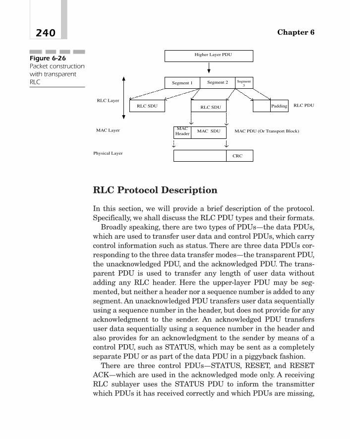
RLC Protocol Description
In this section, we will provide a brief description of the protocol.Specifically, we shall discuss the RLC PDU types and their formats.
Broadly speaking, there are two types of PDUs—the data PDUs,which are used to transfer user data and control PDUs, which carrycontrol information such as status. There are three data PDUs cor-responding to the three data transfer modes—the transparent PDU,the unacknowledged PDU, and the acknowledged PDU. The trans-parent PDU is used to transfer any length of user data withoutadding any RLC header. Here the upper-layer PDU may be seg-mented, but neither a header nor a sequence number is added to anysegment. An unacknowledged PDU transfers user data sequentiallyusing a sequence number in the header, but does not provide for anyacknowledgment to the sender. An acknowledged PDU transfersuser data sequentially using a sequence number in the header andalso provides for an acknowledgment to the sender by means of acontrol PDU, such as STATUS, which may be sent as a completelyseparate PDU or as part of the data PDU in a piggyback fashion.
There are three control PDUs—STATUS, RESET, and RESETACK—which are used in the acknowledged mode only. A receivingRLC sublayer uses the STATUS PDU to inform the transmitterwhich PDUs it has received correctly and which PDUs are missing,
Chapter 6240
Higher Layer PDU
Segment 2Segment 1 Segment3
RLC SDU Padding
MAC PDU (Or Transport Block)MAC
HeaderMAC SDU
RLC PDU
CRC
RLC Layer
MAC Layer
Physical Layer
RLC SDU
Figure 6-26Packet constructionwith transparentRLC

and may also indicate the window size that it is using.20 It can alsobe used by a transmitting entity to request its peer to adjust its win-dow size. The RESET PDU is used to command the other end toreset its protocol state variables and timers so that the two ends maybe synchronized with each other. RESET ACK is simply an acknowl-edgment of the RESET command.
Because the transparent PDU does not contain any header, theRLC PDU has the same format as the higher-layer PDU. The PDUformat for the unacknowledged mode is shown in Figure 6-27. Thesequence number is seven bits long. The E bit allows a field to beextended—if it is 0, it means that the next octet is a data field. If it is1, it means that the next octet includes the length indicator field andthe E bit. The length indicator field gives the size of the data field inoctets.To illustrate the use of the E bit, we notice that it should be setto 1 in the first octet. If E is 1 in the second octet and 0 in the third,we have a 14-bit length indicator field, and in that case, the user databegins from the fourth octet. Similarly, if the E bit is 0 in the secondoctet, the length indicator field is 7 bits wide. The purpose of thepadding field is to ensure that the PDU has the required length.
241Universal Mobile Telecommunications System (UMTS)
20The receiver may acknowledge each packet separately as it comes or may wait untilit receives a number of them, say W, and then acknowledge all of them using a singleacknowledgment message. In that case, W is called the window size.
E
E
E
Sequence No. (7 Bits)
Length Indicator
Length Indicator
Data
Padding Octets
Octet 1
Octet 2
Octet 3
oo
Figure 6-27The RLC PDUformat for theunacknowledgedmode
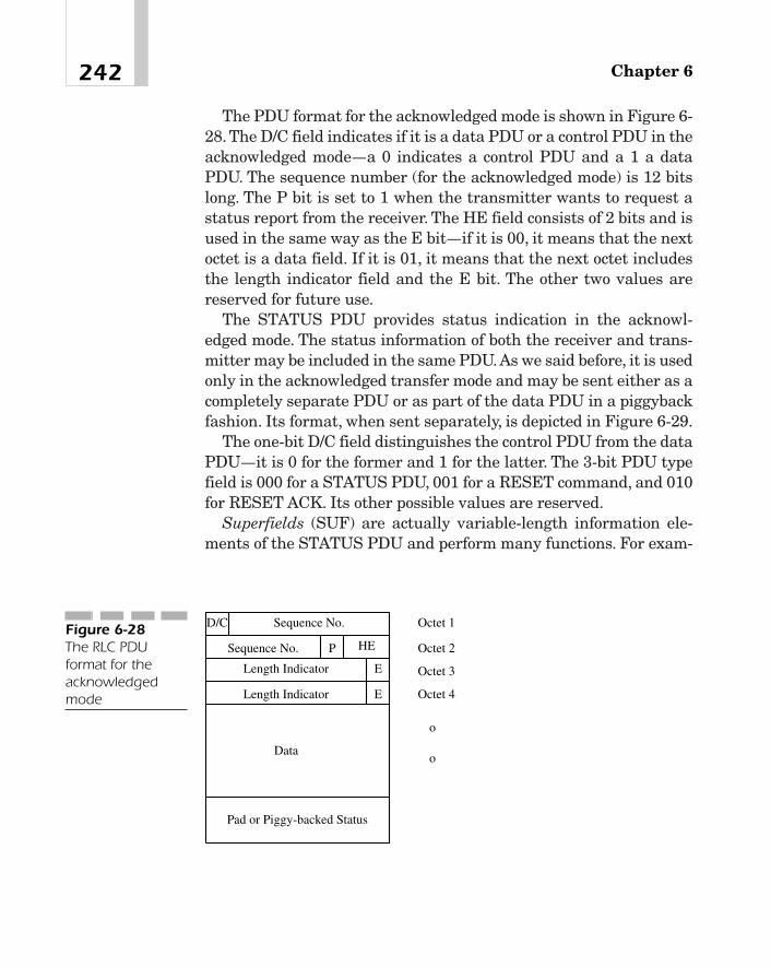
The PDU format for the acknowledged mode is shown in Figure 6-28. The D/C field indicates if it is a data PDU or a control PDU in theacknowledged mode—a 0 indicates a control PDU and a 1 a dataPDU. The sequence number (for the acknowledged mode) is 12 bitslong. The P bit is set to 1 when the transmitter wants to request astatus report from the receiver. The HE field consists of 2 bits and isused in the same way as the E bit—if it is 00, it means that the nextoctet is a data field. If it is 01, it means that the next octet includesthe length indicator field and the E bit. The other two values arereserved for future use.
The STATUS PDU provides status indication in the acknowl-edged mode. The status information of both the receiver and trans-mitter may be included in the same PDU.As we said before, it is usedonly in the acknowledged transfer mode and may be sent either as acompletely separate PDU or as part of the data PDU in a piggybackfashion. Its format, when sent separately, is depicted in Figure 6-29.
The one-bit D/C field distinguishes the control PDU from the dataPDU—it is 0 for the former and 1 for the latter. The 3-bit PDU typefield is 000 for a STATUS PDU, 001 for a RESET command, and 010for RESET ACK. Its other possible values are reserved.
Superfields (SUF) are actually variable-length information ele-ments of the STATUS PDU and perform many functions. For exam-
Chapter 6242
E
E
HEP
D/C Sequence No.
Length Indicator
Length Indicator
Data
Pad or Piggy-backed Status
Sequence No.
Octet 1
Octet 2
Octet 3
Octet 4
o
o
Figure 6-28The RLC PDUformat for theacknowledgedmode

ple, they may indicate if there is more data to follow, inform the peerRLC which PDUs have been received correctly so that the sendingend can repeat a transmission if necessary, and so on. Each super-field may have as many as three subfields:
� Type
� Length
� Value
See Figure 6-30 for an illustration. The type is a four-bit identifierand must always be included. The other subfields are optional. Forexample, the particular SUF, which indicates that there is no moredata to follow, has only the type field (which is 0000). This SUF isplaced at the end of the list of superfields, immediately ahead of thepadding bits, if any.
Another superfield is acknowledgement—it has two subfields: a 4-bit type (0010) and a 12-bit length field called the last sequencenumber (LSN). The receiver uses this superfield to indicate to thetransmitter that it has received correctly all PDUs with sequencenumbers less than the value of the LSN field except for those whichare explicitly indicated as erroneous by the superfield named List(type � 0011). The superfields are shown in Table 6-3.
The piggybacked STATUS PDU has the same format as shown inFigure 6-29 except that the D/C bit is now a reserved bit because itis not needed any more when the status information is included inthe data PDU.
243Universal Mobile Telecommunications System (UMTS)
D/C PDU Type
oo
SUF 1
SUF 2
SUF 3
Pad
SUF N
Figure 6-29The RLC STATUSPDU format
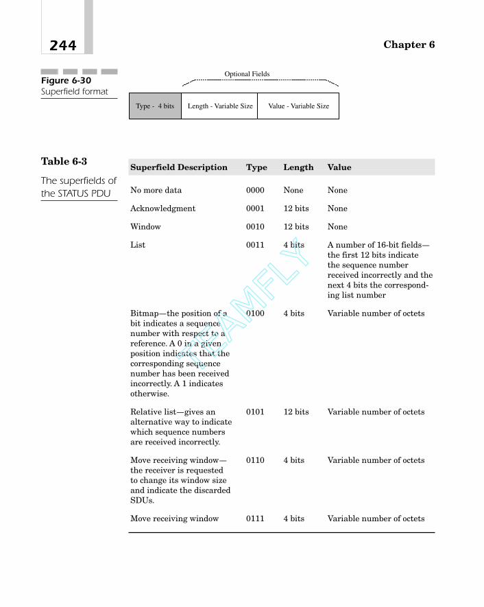
Chapter 6244
Type - 4 bits Length - Variable Size Value - Variable Size
Optional FieldsFigure 6-30Superfield format
Superfield Description Type Length Value
No more data 0000 None None
Acknowledgment 0001 12 bits None
Window 0010 12 bits None
List 0011 4 bits A number of 16-bit fields—the first 12 bits indicatethe sequence numberreceived incorrectly and thenext 4 bits the correspond-ing list number
Bitmap—the position of a 0100 4 bits Variable number of octetsbit indicates a sequence number with respect to a reference. A 0 in a given position indicates that the corresponding sequence number has been received incorrectly. A 1 indicates otherwise.
Relative list—gives an 0101 12 bits Variable number of octetsalternative way to indicate which sequence numbers are received incorrectly.
Move receiving window— 0110 4 bits Variable number of octetsthe receiver is requested to change its window size and indicate the discarded SDUs.
Move receiving window 0111 4 bits Variable number of octets
Table 6-3
The superfields ofthe STATUS PDU
TEAMFLY
Team-Fly®

Packet Data Convergence Protocol (PDCP)
Overview
Currently, the most common protocols for data services are IPv4 andIPv6 at the network layer and TCP and User Datagram Protocol(UDP) at the transport layer. Because new services and applicationsare continually being introduced, it is conceivable that in the future,new network layer protocols would be developed supporting theseservices. As such, it is desirable that the UTRAN be able to inter-work with these emerging protocols without requiring any changesto its RLC or MAC layers. The packet data convergence protocolhelps achieve this goal by adapting different network layer protocolsto the RLC layer so that the user data can be transferred across theUTRAN transparently. Another function of PDCP is to improve thetransmission efficiency for delay-sensitive information such as voiceor video. It does this by reducing the size of the header fields ofupper-layer packets using different header compression and decom-pression algorithms that have been standardized by IETF. In the ini-tial version of this protocol, a separate PDCP entity is used for eachradio bearer. In the later version, however, it will be possible to mul-tiplex two or more radio bearers onto the same RLC PDU using asingle PDCP entity.
PDCP receives the user data from the higher layers, performs theheader compression if requested, and sends the resulting PDCPPDUs to the RLC layer. Notice that these PDUs are nonaccess stra-tum because they are exchanged between the UE and the core net-work, and do not terminate in the UTRAN. The data transferbetween peer RLCs may take place in acknowledged, unacknowl-edged, and transparent modes. In the acknowledged mode, thereceiving RLC, after receiving the data, passes it to its PDCP layerand returns an acknowledgment to its peer. In the other two modes,there is no acknowledgment involved.
245Universal Mobile Telecommunications System (UMTS)

Header Compression
The transmission efficiency depends, to some extent, on the size ofthe packet header compared to the length of the entire packet. Con-sider, for example, IPv6 where the header is 48 octets long. If theuser data in the packet is also 48 octets, the transmission efficiencyis only 50 percent. If 13 kb/s coded speech is being transmitted, itrequires about 29.5 ms of speech samples to construct a packet.21
Thus, large headers not only require higher channel bandwidths anddecrease the transmission efficiency but also increase the delay.
Compression algorithms are based on the fact that many of theheader fields remain the same during the life of a call and do nochange from one packet to another. For example, most of the fields ofan IP header remain constant. Similarly, with TCP and UDP, thesource and destination address and port numbers do not change.Thus, it is sufficient to transmit a packet with the entire header onlyat the beginning of a sequence of packets and thereafter send onlythose fields that have changed in the meantime. The receiving endsaves the full header and uses it to decompress the received header.If, however, the entire header changes at some point, it will be nec-essary to transmit the full header to the receiving end.
Broadcast/Multicast (BMC)ProtocolThis layer 2 sublayer is responsible for transferring messages fromthe network that are to be broadcast or multicast to all mobile sta-tions in a cell. The user data that comes from the higher layers aretemporarily saved in the BMC, if necessary, until they are scheduledfor transmission. The transfer takes place using the unacknowl-edged mode service of the RLC on a common traffic channel to the
Chapter 6246
21At 13 kb/s, the time required to collect 48 octets of speech samples is (48 � 8)/13,000seconds or 29.5 ms.

MAC layer.22 User data that is not intended to be broadcast over acell is passed transparently by the BMC. As for other functions per-formed, this entity on the network side periodically estimates thevolume of the cell broadcast traffic and forwards the information tothe RRC layer using an indication primitive.
There are two types of messages in BMC—the cell broadcast mes-sage from the network and the schedule message that gives the loca-tion of broadcast messages in the next schedule period as well as thelocation of the schedule message for the following period. The BMClayer, on the UE side, determines which messages to forward to itsupper layer and sends an indication to the RRC layer.
The BMC message format is very similar to that of an ISDN callcontrol message and consists of a number of information elements.As an example, the information elements of a cell broadcast messageare shown in Figure 6-31.
Radio Resource Control Protocol
RRC Functions
Radio resources comprise W-CDMA frequencies, different channeltypes, channelization codes, spreading factors, scrambling codes, thecapability to control transmitter power, and so on. The RRC layermanages these radio resources so as to establish, maintain, andrelease connections between UTRAN and the UE. Reference [19]describes in detail functions performed by the RRC, procedures,
247Universal Mobile Telecommunications System (UMTS)
22This is a logical channel.
MessageType
Message IDSerial
NumberCodingScheme
DataFigure 6-31The cell broadcastmessage format

messages, and their constituent information elements, specifiestimers and counters, and discusses specific functions such as trafficvolume measurements and how they are to be reported. In this sec-tion we shall provide a brief overview of the RRC layer.
Among the functions performed at this layer are the following:
� Broadcasting nonaccess stratum user data such as cellbroadcast messages to UE that are transferred transparentlythrough the UTRAN.
� Broadcast of system information. The system informationincludes, among other things, NAS system information, timersand counters used by the UE in the idle mode, user registrationarea (URA) identity and information for periodic cell and URAupdates, parameters for cell selection and reselection,configuration parameters for the common physical channels inthe cell or for the common and shared physical channels in theconnected mode, uplink interference and dynamic persistencelevels for PRACHs, and CPCH parameters to be used in the cell.
� Paging and notification. Paging messages are usually sent byhigher layers to establish a connection. However, paging mayalso be initiated by the UTRAN to force UEs to read the latestsystem information or transition, if necessary, to a known state.
� Initial cell selection and reselection. The UE is required toinitiate cell selection on a designated UTRA carrier and camp on it.
� Management of RRC connections between UE and UTRAN andassociated radio resources.
� Management of radio bearers. A radio bearer is an RLC layerservice for transferring user data between UE and the servingradio network controller. The UTRAN may establish a new radiobearer by sending, to a UE, a RADIO BEARER SETUP messagefrom its RRC layer indicating, among other things, the desireduplink and downlink transport channels, the frequency, and themaximum allowed uplink transmit power.
Chapter 6248

� Support of mobility functions.
� Routing higher-layer PDUs.
� Management of links between opportunity-driven multiple access(ODMA) relay nodes.
� Providing an interworking capability between UTRAN and agateway node.
� Contention resolution in the TDD mode.
� Arbitration of radio resources on the uplink dedicated controlchannel.
� UE measurements and their reporting.
� Admission control or, its broader equivalent, QoS control.
Management of RRC Connections
Because signaling and control information flows through the RRC, itis necessary to establish an RRC connection between the UE andUTRAN. Connections are established, removed, or reestablishedusing layer 3 call control messages. The message constructs and pro-cedures are very similar to those of other network layer protocolssuch as ISDN Q.931. For example, both protocols specify a set of mes-sages, each consisting of a number of information elements and asso-ciated with a set of rules that govern how the particular message isto be initiated and handled.
Here is an example to illustrate the RRC connection procedure.Assume that a UE wants to send some user data to a destinationendpoint. As we previously mentioned, the user data packets do notterminate in the UTRAN, but go all the way to the core network. Todo this, it is necessary, first of all, to establish a connection betweenthe peer RRCs of the UE and UTRAN. To that end, the UE requeststhe UTRAN to initiate an RRC connection. The messages exchangedbetween them are shown in Figure 6-32.
249Universal Mobile Telecommunications System (UMTS)

Handover
Handover is the process by which the communication with a mobilestation is transferred from one radio channel to another. As in nar-rowband CDMA systems, there are different types of handovers—hard handover and soft handover. The hard handover takes placewhen the base stations participating in the handover process oper-ate on different CDMA carriers, thus requiring that all old radiolinks be released before new ones are established. Consequently, thistype of handover causes the received signal to be interrupted eventhough it may be for a short time. In a soft handover, on the otherhand, a mobile station can receive signals from two or more base sta-tions or two or more sectors of one or more base stations at the sametime. As such, the received signal is not interrupted. A soft handoveris possible only when the participating base stations use the sameCDMA carrier frequency, which is usually the case. The IMT-2000supports intracell, intercell, and multibearer handovers. In fact,seamless handover without any perceptible degradation in thereceived signal quality is a desired goal of 3G systems.
The handover in W-CDMA is similar in concept to the handoff pro-cedure in cdmaOne based on the standard IS-95. For example, likecdmaOne, it is also triggered by a measurement of the pilot strength.
Chapter 6250
UE UTRAN
RRC CONNECTION REQUEST
RRC CONNECTION SETUP
RRC CONNECTION SETUP COMPLETE
Figure 6-32RRC connectionprocedure

But there are some significant differences. Recall that in cdmaOne,if the signal strength of a pilot exceeds a given threshold, that pilotis taken to be a candidate for handover and is added to the candidateset. In other words, we do not compare the pilots and then select onethat is relatively stronger. The threshold may be set to different values by different base stations but does not change dynamically. InW-CDMA, on the other hand, a pilot is selected on the basis of its rel-ative signal strength compared to other pilots.
Handover Types As in cdmaOne, there are three types of han-dovers in W-CDMA:
� Soft handover where all cells in a serving area use the same W-CDMA frequency.
� Hard handover where the participating cells operate on differentW-CDMA frequency bands. Here, not only is it necessary tochange the frequency, but also the mode may have to be changed,say, from FDD to TDD.
� Intersystem handover, for example, with GSM. The networkinitiates this handover by issuing a handover command.
For the purpose of handover, the UE maintains a list of the cellsthat it is currently using or may likely use at some point during acall. This list includes the following:
� Active set It consists of all cells that are simultaneouslyinvolved in a communication during a soft handover. The UEdemodulates the received signals from these cells andcoherently combines them to provide diversity. The net gain inperformance depends, among other things, upon the relativepath loss from the participating base stations to the UE andmay be as much as 2 dB or so. An active set contains two ormore cells for an FDD system but only one in a TDD mode.
� Monitored set These are cells that are not in the active set butare monitored by the UE because they are part of the neighborlist.
251Universal Mobile Telecommunications System (UMTS)

� Detected set These are cells that are neither in the active norin the monitored set but are detected by the UE anyway.
In what follows, we shall only describe the soft handover [43].
Soft Handover The soft handover concept is illustrated in Figure6-33. As we just said, the UE maintains an active set for handoverpurposes. The permissible number of cells in an active set is a sys-tem parameter. Assume that cell 1, being the strongest for a givenUE, is the only cell in the active set. If, at a certain instant t1, thepilot associated with cell 2 is sufficiently strong that the difference�1 between the signal strengths of pilot 1 and pilot 2 is less than athreshold, we can say that pilot 2 is usable, and can therefore includeit in the active set. So, from this point on, the UE is in communica-tion with two cells and may, as a result, use diversity combining.Thisthreshold is L � H1, where L is the reporting range, and H1 is theaddition hysteresis. If, at some later time, say, t2, pilot 1 has degradedenough that the difference �2 between pilot 2 and pilot 1 is greaterthan another threshold, pilot 1 is no longer usable and can, there-
Chapter 6252
1t 2t
Pilot ChannelSignal Strength
Soft Handover
Cell 2 added to theactive set
11 HL �<�
2HL�>
Pilot 1 fromCell 1
Pilot 2 fromCell 2
Cell 1 deleted fromactive set
1 �
2�
Figure 6-33Soft handover inUTRAN

fore, be removed from the active list. Thus, from now on, the UE isin communication with only one cell, namely cell 2. This secondthreshold is L � H2, where H2 is the removal hysteresis.
As the mobile moves away from its present cell into the coveragearea of another, the signal level from the present cell will fall withrespect to the signal from the new cell as shown in Figure 6-34. Atinstant t0, the signal strength of the best candidate exceeds pilot 1.Consequently, at that point, we can replace pilot 1 with the new one.This would mean that if pilot 1 was the only member of the activeset, the UE will now be communicating with the new cell exclusively,instead of cell 1. If, on the other hand, there were two or more pilotsin the active set, the weakest pilot is compared with the new andsubsequently replaced if the criterion indicated in the figure is ful-filled. As a result, the UE is now involved in communication withthis new cell as well as all old cells except cell 1 (or a particular sec-tor of a cell).
The UE updates the active set on command from the UTRAN andsends an acknowledgement back. The messages exchanged when theactive set is to be updated are shown in Figure 6-35.
253Universal Mobile Telecommunications System (UMTS)
t0t
Pilot ChannelSignal Strength
3H>
Pilot 1 inActive Set
Candidate Pilot
Candidate Pilot ReplacesPilot 1 in Active Set
Figure 6-34Intercell handover.In this case, all cellshave the same W-CDMA carrier.

SummaryIn this chapter, we have presented a brief description of the UMTSsystem, its features, and the UTRAN network architecture. Theradio interface protocol stack of the UTRAN, which is also the sameas the lower-layer protocols of UE, has been presented in somedetail. More specifically, we have described the physical layer, themedium access control layer, radio link control, the packet data con-vergence layer, the broadcast multicast protocol, and the radioresource control protocol. Procedures such as those used in synchro-nization, power controls, and handovers are also described.
The key features of UMTS W-CDMA may be summarized as fol-lows:
� Wider bandwidth This is a direct-spread CDMA system with anominal bandwidth of 5 MHz. The chip rate is 3.84 Mc/s. A radio
Chapter 6254
Active Set Update
UE UTRAN
Active Set Update Complete
Active Set Update
UE UTRAN
Active Set Update Failure
Figure 6-35Procedure toupdate the activeset
TEAMFLY
Team-Fly®

frame is usually 10 ms long and consists of 15 slots, each ofduration 2,560 chips.
� Asynchronous operation There is no need for cell sites to besynchronized to each other using a global timing reference. Eachcell site may operate in a fully asynchronous manner. However,this requires a different scrambling code for each cell or eachsector of a cell.
� Channel coding Incoming data, depending upon applications,may not be encoded at all or may be encoded into either aconvolutional code of rate 1/3 or 1/2, or turbo code of rate 1/3.
� Spreading codes Physical channels are separated at thereceiver by spreading them with channel-specific OVSF codes. Aspreading factor of 256 is used for control channels. For userdata channels, spreading factors vary from 4 to 256 on uplinksand 4 to 512 on downlinks.
� Scrambling codes Uplink scrambling codes are complex valuedand may be either long or short. The long codes have a length of38,400 chips (that is, 10 ms), whereas short codes are only 256chips long. The short codes are particularly useful for multiuserdetection at base stations. Downlink scrambling codes are alsocomplex-valued. There are a total of 218 � 1 of these codes.However, only 8,192 are used on downlinks. They are dividedinto 512 groups, each containing one primary scrambling codeand 15 secondary scrambling codes. Each code is of length38,400 chips.
� Complex spreading W-CDMA uses complex spreading thatreduces the amplitude variations of the baseband filter output,thus making the signal more suitable for nonlinear poweramplifiers. It also provides better efficiency by reducing thedifference between the peak power and the average power.
� Variable bandwidth Any user equipment may be assigned avariable bandwidth by simply changing the spreading factorsand allocating one or more slots and one or more dedicatedchannels to the UE. Similarly, the system supports multipleapplications simultaneously for the same UE.
255Universal Mobile Telecommunications System (UMTS)
� Packet mode data services W-CDMA UMTS supports a highlyflexible packet mode data service. The multiple-access procedureis based upon the slotted Aloha scheme. Channels that may beused for this purpose include the RACH, CPCH, dedicatedchannels, and FACH.
� Coherent demodulation, multiuser detection, and adaptiveantenna arrays The system has been designed to facilitatecoherent demodulation using pilot bits and supports suchadvanced technologies as beam forming with adaptive antennasand multiuser detection techniques.
� Transmit diversity In contrast to GSM, the performance of W-CDMA can be improved to some extent by implementingtransmit diversity on a downlink channel.
References
General Systems Descriptions
[1] 3G TS 22.105, Service Aspects; Services and Service Capabil-ities.
[2] 3GPP TS 23.107, QoS Concept and Architecture.
[3] 3GPP TS 25.401, UTRAN Overall Description.
[4] 3GPP TS 25.101, UE Radio Transmission and Reception.
[5] 3GPP TS 25.104, UTRA (BS) FDD, Radio Transmission andReception.
[6] 3GPP TS 25.105, UTRA (BS) TDD, Radio Transmission andReception.
Overview of the UE-UTRAN Protocols
[7] 3GPP TS 25.301, Radio Interface Protocol Architecture.
Chapter 6256

Physical Layer
[8] 3GPP TS 25.201, Physical Layer—General Description.
[9] 3GPP TS 25.211, Physical Channels and Mapping of Trans-port Channels onto Physical Channels (FDD).
[10] 3GPP TS 25.212, Multiplexing and Channel Coding.
[11] 3GPP TS 25.213, Spreading and Modulation (FDD).
[12] 3GPP TS 25.214, Physical Layer Procedures.
[13] 3GPP TS 25.215, Physical Layer—Measurements.
[14] 3GPP TS 25.302, Services Provided by the Physical Layer.
Layer 2 and Layer 3 Protocols
[15] 3GPP TS 25.321, MAC Protocol Specification.
[16] 3GPP TS 25.322, RLC Protocol Specification.
[17] 3GPP TS 25.323, Packet Data Convergence Protocol (PDCP)Specification.
[18] 3GPP TS 25.324, Broadcast/Multicast Control (BMC) Proto-col Specification.
[19] 3G TS 25.331, RRC Protocol Specification.
[20] 3G TS 25.303, Interlayer Procedures in Connected Mode.Also, 3GTS 25.304, UE Procedures in Idle Mode and Proce-dures for Cell Reselection in Connected Mode.
Protocols at Different Interface Points
[21] 3GPP TS 25.410, UTRAN Iu Interface: General Aspects andPrinciples.
[22] 3GPP TS 25.411, UTRAN Iu Interface: Layer 1.
[23] 3GPP TS 25.412, UTRAN Iu Interface: Signaling Transport.
[24] 3GPP TS 25.413, UTRAN Iu Interface: RANAP Signaling.
257Universal Mobile Telecommunications System (UMTS)
[25] 3GPP TS 25.414, UTRAN Iu Interface: Data Transport andTransport Signaling.
[26] 3GPP TS 25.415, UTRAN Iu Interface: CN-RAN User PlaneProtocol.
[27] 3GPP TS 25.420, UTRAN Iur Interface: General Aspects andPrinciples.
[28] 3GPP TS 25.421, UTRAN Iur Interface: Layer 1.
[29] 3GPP TS 25.422, UTRAN Iur Interface: Signaling Transport.
[30] 3GPP TS 25.423, UTRAN Iur Interface: RNSAP Signaling.
[31] 3GPP TS 25.424, UTRAN Iur Interface: Data Transport andTransport Signaling for CCH Data Streams.
[32] 3GPP TS 25.425, UTRAN Iur Interface: User Plane Protocolsfor CCH Data Streams.
[33] 3GPP TS 25.426, UTRAN Iur and Iub Interface Data Trans-port and Transport Signaling for DCH Data Streams.
[34] 3GPP TS 25.427, UTRAN Iur and Iub Interface User PlaneProtocols for DCH Data Streams.
[35] 3GPP TS 25.430, UTRAN Iub Interface: General Aspects andPrinciples.
[36] 3GPP TS 25.431, UTRAN Iub Interface: Layer 1.
[37] 3GPP TS 25.432, UTRAN Iub Interface: Signaling Transport.
[38] 3GPP TS 25.433, UTRAN Iub Interface: NBAP Signaling.
[39] 3GPP TS 25.434, UTRAN Iub Interface: Data Transport andTransport Signaling for CCH Data Streams.
[40] 3GPP TS 25.435, UTRAN Iub Interface: User Plane Protocolsfor CCH Data Streams.
Miscellaneous Specifications of Interest
[41] 3G TR 23.922, Architecture of an All IP Network.
[42] 3G TR 25.990, Vocabulary.
[43] 3G TR 25.922, Ver. 0.5.0, Radio Resource ManagementStrategies.
Chapter 6258

Other References
[44] N. Abramson, “The Throughput of Packet BroadcastingChannels,” IEEE Trans. Comm., Vol. COM-25, No. 1, January1977, pp. 117-128.
[45] S.W. Golomb, Shift Register Sequences. Revised Edition,Aegean Park Press, Laguna Hills, CA, 1982.
Web Sites
http://www.itu.int/publications/
http://www.itu.int/imt/2-rad-devt/index.html
http://www.itu.int/brsg/ties/imt-2000/index.html
259Universal Mobile Telecommunications System (UMTS)

This page intentionally left blank.

Evolution ofMobile
CommunicationNetworks
CHAPTER 77
Copyright 2002 M.R. Karim and Lucent Technologies. Click Here for Terms of Use.

As the access part of a mobile communication network is evolvingtowards third generation (3G) to support new air interfaces, so is thearchitecture of the core network. In order to get the maximum returnfrom their investment, service providers want a network that wouldbe adequate for current customer needs, but at the same time be ableto provide new, emerging services by simply adding some new capa-bilities in the form of a hardware and/or software upgrade to theirexisting equipment. Because the second generation wireless systemsare required to support only limited data, such as short messagingservices and slow-speed circuit-switched or packet mode data, thecurrent network is principally circuit-switched, but includes anentity called the interworking function to provide the data capabili-ties. Now, however, the demand for higher data rates is growing at arapid rate. Because packet-switched networks are inherently moreefficient for data services, networks are evolving that combine themore common, ubiquitous circuit-switched fabric with elements of apacket-switched network. One such example is the general packetradio service (GPRS) that can support packet mode data at rates upto about 160 kb/s [9], [10]. In view of the requirements of the 3G sys-tems for both constant and variable bit rate services, the need forsuch a network appears to be even more compelling than ever before.In fact, because of these 3G requirements and emerging applications(such as conversational voice and video, interactive data, high vol-ume data transfer, and so on) with a guaranteed quality of service,the network is gradually evolving to an all-IP architecture [12].
In this chapter, we will discuss this evolution of wireless networks.But first we will review the 3G system requirements so that we canunderstand the driving forces behind the network evolution.
Review of 3G Requirements [1]–[4]3G wireless systems are required to provide traditional voice,enhanced voice, multimedia services, and high-speed circuit andpacket mode data to mobile users as well as special services such aspaging and address dispatch or fleet operation. A mobile station mayrun multiple applications at any time; however, the network isrequired to support, for each mobile station, a total bit rate of
Chapter 7262
� 144 kb/s or more in vehicular operations
� 384 kb/s or more for pedestrians
� About 2.048 Mb/s for indoor or low-range outdoor applications
Some user applications may require bandwidth on demand anda guaranteed quality of service (QoS) from networks. Thus, the corenetwork should be capable of reserving resources based on userrequests and making sure that all users get the requested quality.3G standards call for efficient utilization of the spectrum and, insome cases, phased introduction of these services. Open interfacesshould be used wherever possible. The service quality to be pro-vided to the mobile users is intended to be comparable to thatavailable from fixed networks and should be maintained evenwhen more than one service provider is operating in a serving area.All these services should be provided to each user with an accept-able degree of privacy and security that would be at least as goodas or better than what is currently available over a Public SwitchedTelephone Network (PSTN). Finally, the 3G networks should besynergistic with the architecture of future networks.
The user traffic in 3G may be
� Constant bit rate traffic such as speech, high-quality audio,video telephony, full-motion video, and so on, which are sensitiveto delays and more importantly, delay variations.
� Real-time variable bit-rate traffic such as variable bit-rateencoded audio, interactive MPEG video, and so on. This type oftraffic requires variable bandwidths and is also sensitive todelays and delay variations.
� Nonreal-time variable bit-rate traffic such as interactive andlarge file transfers that can tolerate delays or delay variations.
From these requirements it appears that a hybrid architecturesuch as the one GSM with GPRS enhancements is a possibility for3G systems. However, because more and more of the emerging appli-cations require bandwidth on demand, an all-packet fabric is anattractive alternative, particularly if it can be designed to supportdelay-sensitive real-time applications.
263Evolution of Mobile Communication Networks

Network Evolution
First-Generation Network
We begin with the network reference model of the Telecommu-nications Industry Association/Electronics Industry Association(TIA/EIA) standard IS-41 [5], which is shown in Figure 7-1. This alsorepresents the network for the first generation systems that supportonly voice and no data. This reference model is similar to the GSMarchitecture.
The mobile switching center (MSC) performs mobile switchingfunctions and interfaces the cellular network to a PSTN, IntegratedServices Digital Network (ISDN), or another MSC. Home LocationRegister (HLR) contains a centralized database of all subscribers tothe home system. This database includes such information as theelectronic serial number (ESN), directory number (DN), the serviceprofile subscribed by this user (such as roaming restriction, if any,supplementary services that this mobile has subscribed to, and soon), and its current location. Similarly, Visitor Location Register(VLR) contains a database of all visitors to this particular system.Whenever a mobile station moves into a foreign service area, its
Chapter 7264
BTS MSC HLR
VLRPSTN ISDN
MS
Um
Other MSC
A
B
C
DAi Di
AC
EIR
Figure 7-1The referencemodel of a mobilecommunicationnetwork
TEAMFLY
Team-Fly®

MSC saves all the pertinent information of that mobile station in itsVLR. The home MSC is also notified so that incoming calls to thismobile can be forwarded to the foreign MSC. The information in theVLR is really the same as that of the HLR. However, when themobile moves out of this foreign serving area, its MSC removes thedatabase of this visitor from its VLR. The equipment identity register(EIR) contains the equipment identification number. The authenti-cation center (AC) manages user data-encryption-related functionssuch as ciphering keys, and so on.
The intersystem operations between entities at reference points B,C, and D are specified in the EIA Standard IS-41, which, more specif-ically, define procedures for handoff as a mobile moves from the ser-vice area of one MSC to another and automatic roaming.
IS-634-A [6], [7] defines the interface at reference point A betweenan MSC and a base station. It specifies the interface requirementsfor all types of user traffic and signaling information exchanged overthis reference point. The Asynchronous Transfer Mode (ATM) proto-col is used to transport the following information:
� The coded user traffic (such as user data or low bit-rate speech)and the signaling information between an MSC and a basestation (BS). Separate logical channels carry the user traffic andthe signaling information. These interface functions aredesignated as the A3 interface.
� The signaling information between a source BS that initiallyserves a call and any other BS that supports this call (that is,the target BS). This interface function is designated as the A7interface.
Figure 7-2 shows the protocol stack for these interfaces. Noticethat at the ATM adaptation layer, AAL5 is used for signaling andpacket mode data, and AAL2 for the user traffic. AAL Type 2 isintended for variable-bit-rate, circuit-switched applications wherethe source timing information may have to be transmitted to thereceiving end. AAL Type 5, on the other hand, is used in connection-less, variable-bit-rate services where the receiving end-point doesnot require this timing information.
265Evolution of Mobile Communication Networks

Second-Generation Networks
An important feature of the second-generation (2G) systems is theirdata service capability. For example, IS-95 supports circuit-switcheddata and digital fax, IP, mobile IP, and cellular digital packet data(CDPD). GSM provides the short messaging service and circuit-switched data at rates up to 9.6 kb/s per slot. Figure 7-3 shows a net-work architecture that supports these data services as well as voice.Notice that it is very similar to that of Figure 7-1 except for its inter-face to a public data network (PDN). This interface to the PDN is viaan interworking function labeled IWF, which actually performs someprotocol conversion that might be necessary because of the differ-ences in the protocols used on the mobile stations and the PDN.
To see what kind of protocol conversion is performed by IWF, con-sider Figure 7-4, where we show the protocol stacks between amobile station and a base station and between IWF and PDN forpacket data transmission in an IS-95 system.
The radio link protocol (RLP) accepts a packet from the link layer(that is, the layer above it), segments it into smaller sizes that fit the
Chapter 7266
SignalingPacket Mode
Data
Application Layer
AAL5
ATM
Physical Layer
Control Plane User Plane
AAL5
TCP/UDP
IP
Application Layer
Higher Layers
AAL2
Circuit ModeVoice/DataFigure 7-2
The protocol stackfor A3 and A7interfaces

20-ms frames of a traffic channel, and then passes them to the phys-ical layer where they are transmitted over the radio interface. Thepoint-to-point protocol (PPP) is a byte-synchronous, data link layerprotocol, which takes a datagram packet from the IP layer, adds aframe check sequence, encloses it between two flags, and passes it tothe layer below. The well-known IP layer protocol interconnects twopacket switching nodes and routes an incoming packet to a nextnode en route to its destination. The Transmission Control Protocol
267Evolution of Mobile Communication Networks
BTS MSC HLR
VLR
IWF
PDN PSTN/ISDN
AP
MS
Um
Other Cellular Systems(e.g. cdmaOne, IS-136, etc.)
Other Vendor'sBase Stations
Figure 7-32G wirelessnetwork withpacket dataservices
BSS MSC IWFMS
Um
PDN
Application Layer
TCP/UDP
IP
PPP
RLP
Physical Layer(IS-95A)
IP
LLC
MAC
Physical Layer
Application Layer
TCP/UDP
Figure 7-4Protocol stacks atthe reference pointUm between amobile station anda base station, and between IWFand PDN

(TCP) at the transport layer guarantees reliable data transfer byproviding error recovery on an end-to-end basis. The MAC layer pro-tocol is IEEE-802.3 or IEEE-802.5, which along with the logical linkcontrol (IEEE-802.2) forms the link layer protocol on the fixed side.
The 2G GSM network was shown in Figure 5-12 [8]. There isreally not much difference between that network and the one shownin Figure 7-3 except for the fact that the MSC of the GSM networkmay additionally include an echo canceler and an audio transcoder.
2G� Networks
Notice that in Figure 7-3, except for the IS-634-A interface betweena BS and an MSC, the core network is circuit-switched. Equipmentfrom many different manufacturers is now available in the marketthat can support packet mode data in a core network. One possiblearchitecture around which many new networks are being built isshown in Figure 7-5.
The salient features of this architecture are the following: First, itconsists of a backbone network that is based on IP/ATM. The use ofATM appears to be almost natural because the interface on the radio
Chapter 7268
BTSoo
BTS
BTS
BSC
BSCoo
A-Interface
A-bisInterface
BSS
MS
Um (AirInterface)
Router
PSTN/ISDNPDN (e.g.
the Internet)
CallFeatureServer
AP forMPEG-2,
etc.
UserDataBase
QoSManager
Billing &CustomerService
Router
IP/ATM Network Gateway MobilityServer
MediaGateway
o o oFigure 7-5The evolution of the corenetwork. The core network ispacket switched.Recall that the Ainterface is basedon IS-634-A.

network controllers, which as we said before is IS-634-A, alreadyuses ATM at the link layer. Furthermore, ATM has high-bandwidthcapability, and provides low delays and bandwidth-on-demand withguaranteed QoS.
Second, it interfaces to legacy networks in a rather straightfor-ward way. For example, the media gateway performs the necessaryprotocol conversion between the backhaul ATM network and thecircuit-switched PSTN or ISDN. The IP routers are used to routepackets to or from IP-based packet data networks. The mobilityserver, which is based on IP, supports mobility management, con-nection control, and signaling gateway functions to help provideseamless roaming capability across different networks with central-ized directory management and, if needed, end-to-end security. Assuch, the functional entities of the mobility server would include,among other things, call control, HLR and VLR databases, and radioresources management.
Third, it allows for distributed processing, thus offloading the corenetwork, and provides a platform where new services, features, andapplications (such as a new call feature, an MPEG-2, or MPEG-4application) can be developed, tested, and installed in the networkwhen necessary. Finally, the architecture is compatible with an all-IPnetwork that appears to be the trend of the future.
It’s worth mentioning here that GPRS, which has already beenintroduced in the 2G� version of GSM, supports packet mode dataat rates up to 160 kb/s [9], [10]. The GPRS network, which was dis-cussed in Figures 5-13 and 5-14, is redrawn in Figure 7-6 for the con-venience of the reader. The core network consists of a number ofserving GPRS support nodes (SGSNs), a gateway GPRS supportnode (GGSN), and a packet control unit (PCU). The SGSN, which isactually a router, connects to a BSC via a PCU, which implementsthe link layer protocol. There may be more than one serving GSN inany public land mobile network (PLMN) as shown. Two separatePLMNs are connected through a GGSN.
The GGSN is also a router and is the first entry point of the corenetwork from any external packet data network (such as the Inter-net). The short messaging service gateway MSC (SMS-GMSC) pro-vides the necessary protocol conversion for handling SMS throughthe GPRS network (instead of the traditional GSM network).
269Evolution of Mobile Communication Networks

3G Network
The 3G UMTS network architecture was shown in Figure 6-2 [11].As maybe seen there, the core network combines the circuit-switchedMSC of the 2G network with the packet-switched elements of theGPRS network of Figure 7-6, thus providing both voice and packetmode data services with an integrated fabric. Notice how the GPRSnetwork is evolving into the 3G, where the packet control unit of Fig-ure 7-6 no longer exists as a separate entity, its function now beingintegrated into a radio network controller.
Chapter 7270
IWF
HLRMSCA
SGSN 1
PSTN/ISDN
PDN1 (e.g.The
Internet)GGSN
GbGs
Gn
GiAnotherPLMN
Gp
Gr
Gc
PDN2
Gi
SGSN 2Gn
To otherPDNs
o o
To otherSGSN
BSCVLR
SMS-GMSC
Gd
D
CE
TE MTUm
R
GGSN
PCUBTS
Figure 7-6The GPRS networkarchitecture

All-IP Network
A core network with an all-IP architecture appears very attractivefor a number of reasons. First, because of the tremendous growth inthe use of the Internet over the last few years, new applications areconstantly emerging, supporting terminals that are IP clients. Withan all-IP architecture, it will be easier to bring the benefits of theseapplications to 3G wireless customers. Similarly, there are manyhigher-layer protocols that have been already developed or are in theprocess of development that are IP based, which would be useful inwireless networks. An example of one such protocol is ResourceReservation Protocol (RSVP), which is used to make a reservationrequest in connection with the QoS in a packet-switched network.Thus, if the network is all-IP, we can take advantage of these proto-cols when implementing the QoS.
Second, some protocols designed for a multimedia terminal use IPat the network layer. For example, multimedia terminals in a 3G sys-tem may be based on International Telecommunications Union (ITU)standards H.324 and H.320. In either case, the control and indica-tion signals, when transported across a 3G network, use User Data-gram Protocol (UDP) at the transport layer and IP at the networklayer. Similarly, the H.323 protocol for video conferencing over tradi-tional local area networks (LANs) also uses IP at the network layer.Besides, as the offered load in the system increases beyond its ratedcapacity, a packet-switched network is inherently capable of servingall users with only a slight, almost unnoticeable degradation in theservice quality.
In view of these considerations, the 3G Partnership Projects aredefining an all-IP packet-switch architecture for the core network[12]. This architecture, as we shall see shortly, is actually an evolu-tion of the GPRS network. Some of the fundamental requirementsthat the IP network must meet are the following:
� Mobiles must be able to roam seamlessly from an IP network toa 2G or 2G�, GSM/GPRS network and to earlier versions of a3G network, and vice versa.
271Evolution of Mobile Communication Networks

� Handovers must be supported (a) between any two IP networks,(b) between any two radio access networks within the same IPnetwork, (c) between any two radio network controllers withinthe same UMTS Terrestrial Radio Access Network (UTRAN) inany given IP network, and (d) between an IP network and any2G or 2G� network.
Figure 7-7 shows one of the architectures that the EuropeanTelecommunications Standards Institute (ETSI) is considering as areference model to provide 3G services to mobile subscribers. Forsimplicity, the interface to legacy signaling networks and referencepoints on interfaces have been omitted.
Notice, first of all, that this network is very similar to the GPRSnetwork in Figure 7-6. The serving GSN and the GGSN perform thesame functions as in the GPRS network. However, now, the PCU isnot a separate unit any more, but is integrated into the radio net-work controller. The GGSN forwards packets to the legacy PSTN viathe media gateway (MGW). The purpose of the MGW is to providesome protocol conversion between the packet-switched core networkand the circuit-switched PSTN. For example, user information asso-ciated with real-time applications, such as voice, video, real-time
Chapter 7272
SGSN 1
Applications& Services
GGSN
AnotherPLMN
PSTN
SGSN 2
UTRANTE MTR
GGSN
HSS
Multimedia IPNetwork
EIR MGW MGCF
T-SGW
MRF
CSCF
Figure 7-7A simplified view ofthe all-IP wirelessnetwor

data, and so on, is transported across a packet-switched networkusing real-time protocol (RTP), TCP/UDP, and IP. The PSTN, on theother hand, transports the user information as circuit-switched datawithout any overhead or encapsulation that is implicit in a packetmode transmission. Similarly, some transcoding function may berequired in the MGW.
The home subscriber server (HSS), which is similar to the HLR of2G and 2G� networks, is a database of all subscribers to the homesystem. It contains the user identity, call features and services sub-scribed by the user, authorization information, and so on. However,unlike the HLR, it must now communicate with other elements ofthe network via IP.
The call state control function (CSCF) works in conjunction withHSS to perform call control procedures. For example, it establishes,maintains, and tears down a call, analyzes and translates theaddress when there is an incoming call, performs call screening andcall forwarding, checks call restrictions (if any) on outgoing calls,and so on.
The multimedia resource function (MRF), which is similar in con-cept to a multi point control unit in traditional video conferencingusing H.323, performs multi party and multi media conferencing.
The media gateway control function (MGCF) works in conjunctionwith the CSCF and transport signaling gateway (T-SWG), and per-forms protocol conversion on the signaling information for calls thatoriginate or terminate in a PSTN. This is necessary because the callcontrols in the core network are IP based, whereas those in thePSTN may use different protocols such as R1, R2, Q.931, and so on.
SummaryIn this chapter, we have discussed the evolution of the core networkof a mobile communication system. Because the second generationsystems are required to have only limited data capabilities, such asshort messaging services and slow-speed circuit-switched, or packetmode data, current networks are principally circuit switched. Dataservices are provided in these networks by means of an entity called
273Evolution of Mobile Communication Networks

the interworking function that interfaces the core network to anexternal PSTN or PDN. With the increasing demand for higher datarates, networks are emerging that still include a circuit-switchedmobile switching center, but use elements of a packet-switched net-work more extensively than before. One such example is the GPRSthat can support packet mode data at rates up to about 160 kb/s.Because in 3G, a subscriber may run multiple applications simulta-neously involving conversational voice and video, interactive data,high volume data transfer, and so on, with a guaranteed QoS, itappears that an all-packet fabric is a possibility for 3G networks,particularly if it can be designed to support delay-sensitive real-timeapplications. In fact, ETSI is defining a standard adopting an all-IParchitecture to deliver 3G mobile telephone services to subscribers.
References[1] IMT-2000: Recommendations ITU-R M.687-2, 1997.
[2] IMT-2000: Recommendations ITU-R M.816-1, “Frameworkfor Services Supported on International Mobile Telecommu-nications-2000 (IMT-2000),” 1997.
[3] IMT-2000: Recommendations ITU-R M.1034-1, “Require-ments for the Radio Interface(s) for International MobileTelecommunications-2000 (IMT-2000),” 1997.
[4] 3G TS 22.105 Release 1999, Services and Service Capabili-ties.
[5] EIA/TIA/IS-41.1-B, Cellular Radio—TelecommunicationsIntersystem Operations: Functional Overview, 1991.
[6] EIA/TIA/IS-634-A, MSC-BS Interface (A-Interface) for Public800 MHz, 1998.
[7] M.R. Karim, ATM Technology and Service Delivery. New Jer-sey: Prentice Hall, 1999, Chapters 1 and 2.
[8] A. Mehrotra, GSM System Engineering. Norwood, MA:Artecth House, 1997.
[9] GSM 03.60: GPRS Service Description, Stage 2.
Chapter 7274
TEAMFLY
Team-Fly®
[10] GSM 03.64: Overall Description of the GPRS Radio Interface,Stage 2.
[11] 3GPP TS 25.401: UTRAN Overall Description, 2000.
[12] 3GPP TR 23.922: Architecture for an All IP Network, 1999.
275Evolution of Mobile Communication Networks

This page intentionally left blank.

Call Controlsand MobilityManagement
CHAPTER 88
Copyright 2002 M.R. Karim and Lucent Technologies. Click Here for Terms of Use.

The purpose of this chapter is to provide the reader with a general,high-level concept of call controls (CC) and mobility management(MM) in wireless networks. Call controls are concerned with signal-ing procedures for establishing or releasing a call and sending mis-cellaneous messages (such as a status enquiry, status, information,congestion control, notifications, and so on) when a call is active. Theterm MM refers to location updates and location reporting as amobile moves around from the coverage area of one radio networkcontroller (RNC) to another or from one system (that is, a core net-work) to another and includes the registration of mobile stations(MS) and their authentication at appropriate instants. Authentica-tion is the process by which the network validates the identity of amobile subscriber. Whenever an MS performs a location updatewhen relocating from the serving area of one mobile switching center(MSC) to another MSC or when it requests service, it may berequired to go through the authentication process.1 Some networksmay also provide, on an optional basis, encryption of user dataexchanged over the air interface, using a ciphering key that isderived during authentication.
To understand call control procedures, knowledge of signaling pro-tocols is helpful. As such, we begin with a brief description of proto-col stacks at reference points between an MS and a Base TransceiverStation (BTS), between a BTS and a MSC, and, for some systems,between an MSC/Visitor Location Register (VLR) and a Home Loca-tion Register (HLR). The Radio Access Network Application Part
Chapter 8278
1Authentication is performed in the following way. When the VLR determines that itis necessary to authenticate a subscriber’s identity, it requests the Authentication Cen-ter (AUC) (via the HLR) to send the required authentication parameters. Thereupon,the AUC generates (1) a random number and, using the authentication key that hasbeen assigned to the MS at the subscription time, derives (2) a data sequence, say, S1,and (3) a ciphering key. On receiving these three parameters from the AUC, the VLRforwards them to the MSC. The MSC, in turn, sends the random number to the MS.In response, the MS fetches the authentication key that is stored in its memory anduses it and the received random number to derive a data sequence S2, and sends it tothe MSC. The MSC compares S1 and S2, and if the two match, the authenticationprocess is successful. In that case, a network may provide encryption of user data overthe air interface as an optional service. The user data in either direction may beencrypted using the ciphering key that was generated by the AUC in the authentica-tion process.

(RANAP) provides signaling and control procedures between aUMTS Terrestrial Radio Access Network (UTRAN) and the core net-work. Functions performed by this protocol, messages exchangedwhen assigning radio resources (such as channels) during a han-dover, and CC messages exchanged when a call is initiated are brieflydescribed. The chapter concludes with an example CC scenario.
Protocol Stacks in Access and Core NetworksBecause the core network and protocols used in Universal MobileTelecommunications System (UMTS) are similar to those of GlobalSystem for Mobile Communications (GSM), we will begin the chapterwith a brief description of the GSM protocols.
GSM
The signaling protocol stacks in the GSM core and access networkare shown in Figure 8-1. The interface between a base station con-troller (BSC) and an MSC (that is, the interface A) is based on theSignaling System 7 (SS7) protocol [10], [11]. At the physical layer, ituses Message Transfer Part (MTP) Level 1, and generally operates at
279Call Controls and Mobility Management
MSA
BTS BSC MSC+VLR HLRA-bisUm
SCCP and MTPLevel 3
MTP Level 2
MTP Level 1
SCCP and MTPLevel 3
MTP Level 2
MTP Level 1
LAPD
Physical Layer
CC, MM andBSS MAP for
Radio Resources
MAP
TCAP
Modified LAPD
Physical Layer
Application Layerfor CC, MM and
RR
Application Layerfor CC, MM andRadio Subsystem
Management
C/D
Figure 8-1The signalingprotocol stacks inGSM

64 kb/s on a DS0 time slot of an E1 interface. MTP Level 2 is a linklayer protocol that specifies the frame format, functions, and proce-dures for transferring user part information over a signaling datalink. MTP Level 3 provides for the distribution and routing of con-nectionless signaling messages to different nodes and is also respon-sible for managing signaling links.
The Signaling Connection Control Part (SCCP) provides addi-tional functions to MTP Level 3, supporting both connectionless andconnection-oriented services to transfer signaling informationbetween nodes (such as MSC, RNCs, exchanges, and specialized cen-ters).2 It controls logical signaling connections in an SS7 network,allowing signaling messages to be routed to a signaling point basedupon, for example, the dialed digits.
The transport, session, and presentation layers are not used in theaccess or core network. The application layer performs call controlsand mobility management, and manages radio resources (RR) suchas radio channels, spreading codes, scrambling codes, and so on. CCand MM messages originate at an MSC and terminate on an MS,and vice versa. Thus, they are carried transparently over the accessnetwork.
The RR protocol manages physical channels (that is, radio con-nections) and specifies procedures for broadcasting system parame-ters, setting up radio connections between the network and an MS,reporting signal-level measurements and performing a handoffwhen a call is in the active state, and releasing all dedicated chan-nels at the end of a call. The system parameters include the networkidentifiers, control channels to be used for signaling purposes withinthe system, options supported by the system, cell selection parame-ters, and so on. The protocol responsible for providing RR messagesbetween an MSC and a BSC is the Base Station System MobileApplication Part (BSSMAP).
The protocol stack on the A-bis interface consists of the physicallayer, the data link layer, and the application layer. It does not haveany network, transport, session, or presentation layer protocol. The
Chapter 8280
2Specialized centers may be databases that translate special numbers or containinformation to invoke an Advanced Intelligent Network (AIN) function.
signaling links on this interface operate at 64 kb/s at the physicallayer, and use the Integrated Services Digital Network (ISDN) LinkAccess Procedure on the D channel (LAPD) protocol at the link layer[9]. The application layer protocols for CC and MM are the same asthose of the A interface. RR messages between a BTS and BSC areprovided by the Radio Subsystem Management (RSM) protocol.
The protocol stack on the Um interface, like the A-bis interface,consists of the physical layer, the data link layer, and the applicationlayer only. The physical layer is the GSM air interface. The link layerprotocol is similar to the ISDN LAPD except that it now uses theframing for the air interface. The application layer protocols for CCand MM are the same as those of the A interface. RR messagesbetween a BTS and MS are provided by the Radio Interface Layer(RIL) 3, while those between the MSC and an MS are supported bythe Data Transfer Application Part (DTAP) protocol.
The lower three layers of the protocol stack at the interfacebetween MSC/VLR and HLR (that is, the C and D interfaces) are thesame as for the A interface. Recall that an HLR contains a databaseof home subscribers such as their identification numbers, their ser-vice profile, and their present location. A VLR contains a database ofall subscribers who are currently visiting this system, and includesthe identification number and current location of the visiting sub-scribers and parameters used in the authentication process. TheMobile Application Part (MAP) is an application layer protocol [9],and interfaces the Transaction Capabilities Application Part (TCAP)[12]. The term transaction capabilities refers to functions providedby protocols that lie above the network layer and extend to the appli-cation layer. These functions are not application specific, but arerather common to applications. The TCAP protocol performs trans-action-based services between node pairs. To execute a transaction,the participating nodes exchange data using a query and responsemechanism. MAP messages are not CC messages, but are neverthe-less required for the successful completion of a call. For example,when an MSC detects that a roaming mobile has registered in itsserving area, its VLR sends a MAP message (that is, a RegistrationNotification message) to the HLR of the visiting mobile, and mustreceive all relevant information from the HLR database before thisMSC can provide service to the roaming mobile.
281Call Controls and Mobility Management

The signaling protocol for the interface between a base station andan MSC (that is, the A interface) in IS-136, IS-95, and cdma2000 alsouses MTP and SCCP in the lower three layers. Messages on thisinterface are specified by IS-634 [15], [13]. The intersystem opera-tions (that is, operations required by handoff, automatic roaming,and so on) are specified in IS-41. For a description of these protocols,see Reference [14].
UMTS
The UTRAN protocol model [1], [2] was discussed in Chapter 6, “Uni-versal Mobile Telecommunications System (UMTS)” and is redrawnin Figure 8-2 for ease of reference.
The RNC controls radio resources of the access network throughone or more BTSs (also called node B). An RNC usually connects tomultiple BTSs on one side and to an MSC and a serving GPRS sup-port node (SGSN) (not shown in this figure) on the other side. AUTRAN may consist of one or more RNCs. An RNC, with its associ-ated BTSs, forms a radio network subsystem (RNS).
Protocols at Uu and Iub Reference Points The UTRAN proto-col stack is conceptually similar to the GSM protocol stack. TheRadio Resource Control (RRC) protocol is a layer 3 protocol in the sig-naling plane that provides management of radio resources. Above itis the application layer protocol for CC and MM functions.The PacketData Convergence Protocol (PDCP), Broadcast/Multicast Control(BMC), Radio Link Control (RLC), and Media Access Control (MAC)are link layer protocols, and were discussed in some detail in con-nection with UMTS. Recall that the RLC protocol supports threemodes of data transfer: transparent, unacknowledged, and acknowl-edged. The physical layer of the Iub interface may operate at differ-ent data rates, such as E1, Synchronous Optical Network (SONET),and so on, over coaxial cables or fiber optics, among other things.
The protocol stack at the Uu interface is similar to the one shownin Figure 8-2 with some differences. For example, its physical layeris the W-CDMA air interface. As discussed in Chapter 6, the physicallayer functions, which are provided by a BTS, include channel
Chapter 8282
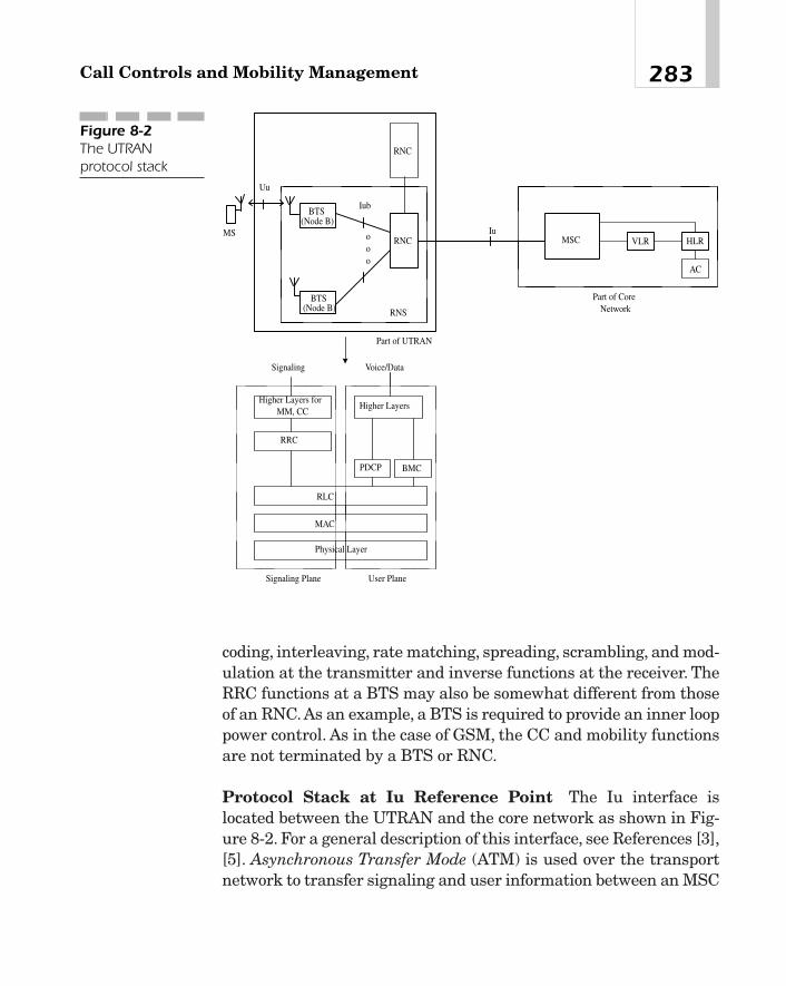
coding, interleaving, rate matching, spreading, scrambling, and mod-ulation at the transmitter and inverse functions at the receiver. TheRRC functions at a BTS may also be somewhat different from thoseof an RNC. As an example, a BTS is required to provide an inner looppower control. As in the case of GSM, the CC and mobility functionsare not terminated by a BTS or RNC.
Protocol Stack at Iu Reference Point The Iu interface islocated between the UTRAN and the core network as shown in Fig-ure 8-2. For a general description of this interface, see References [3],[5]. Asynchronous Transfer Mode (ATM) is used over the transportnetwork to transfer signaling and user information between an MSC
283Call Controls and Mobility Management
BTS(Node B)
BTS(Node B)
RNCooo
MSC VLR HLRMS
Uu
Iu
Iub
AC
RNS
Part of UTRAN
Part of CoreNetwork
PDCP BMC
RLC
MAC
Physical Layer
Higher Layers
Signaling Voice/Data
Signaling Plane User Plane
RRC
Higher Layers forMM, CC
RNC
Figure 8-2The UTRANprotocol stack

and RNCs. Because the UMTS supports circuit-switched (CS),packet-switched (PS), and broadcast (BC) services, the core networkmay be thought of as being composed of three logical domains: CS,PS, and BC. Clearly, to provide these services, separate signaling anduser data connections are required over the Iu interface to each ofthese domains. In what follows we will only describe the protocolarchitectures that govern the signaling and user data connections tothe CS and PS domains.
In the protocol description, use is made of the control plane anduser plane. The control plane is concerned with the establishment,maintenance, and release of links for signaling and control purposes.The user plane, on the other hand, is associated with the exchange ofuser data such as voice or data. In the same way, the transport net-work makes use of a control plane for signaling information and auser plane for transferring user data across the transport network.In this description, we will only be concerned with the transportnetwork user plane protocols. For a description of the transport net-work control plane protocols, see Reference [7].
The signaling protocol stack at the Iu interface for circuit-switchedservices is shown in Figure 8-3(a). Signaling messages are specifiedby RANAP [6], which is a user function of SCCP. SCCP provides sig-naling connections between an RNC and the CS domain of the corenetwork. Both connectionless and connection-oriented proceduresare provided, and a separate connection is required between an RNCand the core network for each active user equipment (UE).
Message Transfer Part Level 3 of Broadband (MTP3-B) SS7 isresponsible for routing and distributing a message and the manage-ment of signaling links so as to ensure proper load sharing.
The next three layers—the Service Specific Coordination Function(SCCF), the Service Specific Connection-Oriented Protocol (SSCOP)and the ATM Adaptation Layer 5 (AAL-5)—constitute the SignalingATM Adaptation Layer-Network Node Interface (SAAL-NNI).Because the application layer protocols are service-specific, thesethree layers adapt the requirements of the upper layers to those ofthe ATM layer. Thus, for example, the SSCF layer processes thepackets from the layer above it so that they become suitable fortransmission over the layer below. The next layer, the SSCOP, pro-vides for connection management, such as setting up and discon-
Chapter 8284
TEAMFLY
Team-Fly®

necting a call, and allows for a reliable exchange of signaling mes-sages. AAL-5 may be used for connectionless or connection-orientedservices that do not require any timing information to be sent fromthe source to the destination. Two operational procedures are avail-able: assured and nonassured. In the first, each AAL service dataunit (AAL-SDU) is delivered to its destination error-free using
285Call Controls and Mobility Management
Signaling
RANAP
SCCP
MTP3-B
SSCF
SSCOP
AAL5
ATM
Physical Layer
SAAL-NNITransport Network
Layer
Radio NetworkLayer
Transport Network User Plane
Figure 8-3The protocol stack for the Iuinterface in UMTSsupporting circuit-switched services. (a) Signaling plane.(b) User plane.
Circuit-switchedUser Data/Voice
Application Layer
TransportNetwork Layer
Radio NetworkLayer
AAL2
ATM
Physical Layer
Transport Network User Plane
(a)
(b)

retransmission and flow control if necessary. In the second proce-dure, there is no guarantee that a given AAL-SDU will be deliveredcorrectly.
The user plane protocol stack for a CS-domain is shown in Figure8-3(b). The ATM Adaptation Layer Type 2 (AAL2) performs circuitemulation of connection-oriented services. It allows the timing infor-mation to be transferred from the source to the destination so thatthe user data can be delivered at precise instants as required by theapplication (such as voice), and provides a means for tracking lostand misinserted cells. If the incoming data blocks are large, the seg-mentation and reassembly (SAR) sublayer of AAL-2 segments eachblock into a number of smaller blocks so that they can fit into ATMcells and sends them out in a sequence [13]. The physical layer foruser data may operate at different rates such as 1.5, 2.0, 51, 155, 622Mb/s, and so on over fiber optics or coaxial cables. The signaling pro-tocols to establish or tear down AAL-2 connections over the trans-port network are provided by the access link control applicationspart (ALCAP), and may be found in Reference [7].
The protocol stack on the Iu interface point for packet-switchedservices is shown Figure 8-4. The signaling protocol model, which isshown in Figure 8-4(a) is similar to that of Figure 8-3(a). M3UA isthe SS7 Message Transfer Part 3—User Adaptation Layer. TheStream Control Transmission Protocol (SCTP) permits different sig-naling protocols to be transported over IP networks.
The IP protocol in the control and user planes is actually IP overATM, where an IP packet is encapsulated with an 8-octet headerbefore it is sent out over ATM. The header is constructed so as touniquely identify each protocol type (such as IP, ATM Address Reso-lution Protocol, and so on). Consequently, a receiving ATM device canforward each incoming packet to the proper entity (such as an IProuter) based on this header alone. Furthermore, it is now possible touse a single ATM virtual circuit (VC) for different applications. For adetailed description of IP over ATM, see [13].
The GPRS Tunneling Protocol (GTP-U) is used to transfer IPdatagrams between two GTP-U endpoints in the user plane. TheGTP-U tunnels are set up and torn down using RANAP. The conceptof a tunneling protocol was introduced in connection with GPRS in
Chapter 8286
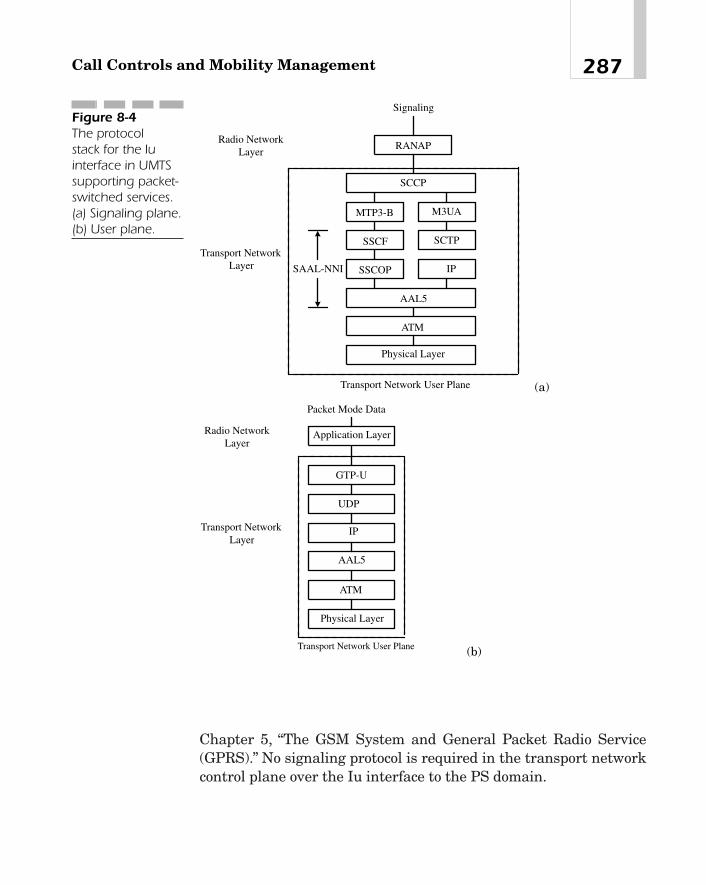
Chapter 5, “The GSM System and General Packet Radio Service(GPRS).” No signaling protocol is required in the transport networkcontrol plane over the Iu interface to the PS domain.
287Call Controls and Mobility Management
Signaling
RANAP
SCCP
MTP3-B
SSCF
SSCOP
AAL5
ATM
Physical Layer
SAAL-NNI
Transport NetworkLayer
Radio NetworkLayer
Transport Network User Plane
M3UA
SCTP
IP
Figure 8-4The protocol stack for the Iuinterface in UMTSsupporting packet-switched services. (a) Signaling plane.(b) User plane.
Packet Mode Data
Application Layer
ATM
Transport NetworkLayer
Radio NetworkLayer
AAL5
Transport Network User Plane
GTP-U
UDP
IP
Physical Layer
(a)
(b)

RANAP [6] RANAP provides signaling between a UTRAN and acore network (CN), and supports both connection-oriented and con-nectionless transfers of user data. For connection-oriented services,signaling links are established or removed dynamically. RANAP isnotified if any of these connections fail at any time. Some of the func-tions performed by RANAP are listed here:
� Management of radio access bearers (RAB) RANAP providesfor the establishment, maintenance, and release of RABs. Theterm RAB is used to indicate the service provided by theUTRAN when user data is to be transferred between a UE anda CN. For example, it may include physical channels over the airinterface, logical channels for packet mode data, etc. Althoughthe overall responsibility for managing RABs and signalingconnections resides with the CN, an RNC may request theirrelease at any time.
� Relocation of a serving RNC As an MS moves from the domainof one RNC to another, or from one serving area to another, theMS is to be handed over to a new RNC (or another system), andso radio resources must be reassigned. To maintain thecontinuity of service, it may be necessary to establish some newsignaling connections or tear down some old ones. Similarly,RABs may have to be added or deleted, depending upon the newlocation of the UE.
� Resetting of Iu interface RANAP may reset an Iu interfaceunder certain conditions.
� Load balancing of an Iu interface RANAP provides proceduresfor controlling the load on an Iu interface so that it remainswithin its prescribed limits.
� Paging RANAP provides for paging a UE.
� Transferring non-access stratum (NAS) signaling messagesbetween a CN and a UE NAS messages are those messagesthat are exchanged between a CN and a UE transparently to theUTRAN. In other words, these messages do not terminate on theUTRAN. A signaling message may be sent to set up a newconnection. On the other hand, a signaling message could also besent over an already existing connection.
Chapter 8288

� Location reporting from an RNC to a CN RANAP allows anRNC to report the location information of a mobile station to aCN. Similarly, it includes procedures to activate or deactivatelocation reporting.
� Security functions RANAP supports transmission of encryptionkeys that provide protection against eavesdropping. Similarly,there are procedures in the protocol for enabling or disabling thesecurity mode.
� Reporting error conditions The protocol includes procedures forreporting general error conditions. As an example, when thesystem fails to transmit a data segment associated with anRAB, the likely cause for failure may be reported to themanagement layer.
RANAP defines a set of elementary procedures that can be used torealize any of the previous functions. When a source end sends amessage requesting the receiving end to perform a specific function,the receiver executes the command and reports the result to thesource. To illustrate the general ideas, suppose that the CN requestsan RNC to assign an RAB. On receiving the message, the RNCattempts to configure the requested RAB if it is available and sendsan RAB assignment response message that includes the followinginformation:
� RABs that have been successfully connected
� RABs that have been successfully released
� RABs that have been queued
� RABs that the RNC has failed to configure
� RABs that the RNC has failed to release
The exchange of messages is shown in Figure 8-5. The figureassumes that the requested operation was successful. If, however,the RNC fails to configure the requested RAB, it includes in theresponse message as precise a cause of failure as possible. For exam-ple, the cause may be “Invalid RAB Parameter Value,” “RequestedMaximum Bit Rate Not Available,” “Requested Transfer Delay NotAchievable,” and so on.
289Call Controls and Mobility Management

A relocation or handoff is handled by RANAP in the followingway. When the source RNC (that is, the presently serving RNS)determines that a handoff is necessary, it sends a RELOCATIONREQUIRED message to the CN. If it is an intrasystem handoff, inother words, if the mobile is merely being transferred from oneRNC to another within the same core network, the source RNCincludes in the message its own ID as well as the ID of the targetRNC. If it is an intersystem handoff, that is, if the relocationinvolves another CN, the message must indicate the identifier ofthe current service area as well as the identifier of the cell in thetarget system. The message also provides a cause value for thehandoff. For example, this cause value may be “Time Critical Relo-cation,” “Resource Optimization Relocation,” or “Desirable Reloca-tion for Radio Reasons,” and so on. The message may also containother information such as the number of Iu signaling connectionsto the UE and so on.
On receiving the RELOCATION REQUIRED message, the CNsends a RELOCATION REQUEST message to the target RNC (ortarget CN), requesting it to schedule necessary resources required bythe source RNC. If the target RNC (or target CN) is able to supportthe requested service, it sends a RELOCATION REQUESTACKNOWLEDGE message to the CN, indicating that necessaryresources in the target RNC have been prepared.
On receiving the acknowledgment from the target RNC, the CNsends a RELOCATION COMMAND to the source RNC. If the targetRNC does not support all the RABs that are required by the UE, theCN may include in the RELOCATION COMMAND a list of all the
Chapter 8290
RNC CN
RAB Assignment Request
RAB Assignment Response
RAB Assignment Responseoo
Figure 8-5A typical RANAPprocedure. Here,the CN requeststhe RNC to assignan RAB for aparticularapplication. TheRNC successfullyassigns the RAB.

RABs that are not going to be supported by the target RNC. At thistime, the source RNC may actually handoff the UE to the target RNC.
If the CN or the target RNC is unable to honor the relocationrequest from the source RNC, the CN sends a RELOCATIONPREPARATION FAILURE message that includes the cause for thefailure. The failure may be due to the target RNC or the target CNnot being able to support the relocation, or the source CN not receiv-ing any response from the target RNC/CN within a specific timeoutperiod. These message flows are depicted in Figure 8-6.
Call ControlsCall controls in different systems are conceptually similar. Supposethat an MS is visiting a new serving area. Before the subscriber caninitiate or receive a call, it must register with the new system. In thiscase, the following sequence of events takes place:
1. To request or receive the service from an MSC, an MS mustregister with the system by sending its identification number.When an MS has moved into a new area, it may autonomouslyregister with that system. Alternatively, if the mobile originatesa call after moving into the new area before the registrationprocess begins, the VLR may ask the MS to register. In eithercase, after the registration process is complete, the VLR of thenew serving area has the identity of the mobile subscriber.
291Call Controls and Mobility Management
SourceRNC
CN
RELOCATION REQUIRED
RELOCATION COMMAND
TargetRNC/CN
RELOCATION REQUEST
RELOCATION REQUESTACKNOWLEDGE
Allocatesresources
Executesrelocation
Figure 8-6Relocationprocedure

The MS may use the following procedure to determine that ithas moved into a new location area. The MS fetches from itsmemory the identifier of the location area in which it was lastregistered, and compares it with the corresponding informationthat is being broadcast by the system along with other systemparameters. If the two do not match, the MS knows that it isvisiting a foreign serving area, and initiates an autonomousregistration.
2. This VLR notifies the HLR of the visiting subscriber about theregistration that just took place, whereupon the HLR updatesthe present location of the subscriber so that if there is anincoming call to this mobile, the HLR knows how to route thecall.
3. The HLR also sends a registration cancellation message to theVLR of the area that this subscriber had last visited. This latterVLR may then request its associated MSC to delete allinformation about this subscriber from its memory.
4. The VLR of the new serving area may send a qualificationrequest message to the HLR to determine if the visitingsubscriber is authorized to receive the service. In response, theHLR checks its database, and sends the required informationalong with other optional, relevant parameters.
5. Notice that the VLR of the new serving area does not have thedatabase of the MS yet, and so requests the HLR to send theprofile of the MS. When it receives the requested information, itsaves that information in its database. The visited area is nowready to serve the MS.
The message flow that takes place during the registration phaseis shown in Figure 8-7. These messages are specified by the MAPprotocol [14]. There are other MAP messages that perform differentfunctions. For example, an MSC may send a message to anotherMSC, requesting it to take measurements for a required handoff. Or,it may send a location request message to an HLR, seeking informa-tion about the current location of an MS, and so on. Message formatsare specified by TCAP. A TCAP message is initiated by a TCAPinvoke, which is followed by a TCAP result. When an entity, such as
Chapter 8292

an HLR or VLR, receives this message, it executes the task specifiedor implied by the message and sends the result to the source.
Many different call scenarios are possible. For example, there maybe a land-originated call to an idle MS in a home system or in a vis-ited system. In a second scenario, a call comes to an MS that has anunconditional call-forwarding feature activated. Or, a call is deliv-ered to an MS that is inactive while visiting a service area, and so on.In what follows, we will only illustrate the sequence of events thattake place when a land-originated call is directed to an idle mobilestation in a visited system. The message flow is shown in Figure 8-8.
1. A land-originated call destined to an MS comes to the MSC ofthe home location, that is, the originating MSC. Because theHLR contains the information on the current location of the MS,this MSC sends a location request to the HLR, asking for thepresent location of the (roaming) mobile.
2. On receiving the location request, the HLR retrieves the locationinformation from its database and sends a routing request to theVLR of the visited system, asking how the call may be bestrouted to the called MS.
293Call Controls and Mobility Management
OldMSC + VLR HLR New
MSCNewVLR MS
Autonomous Registration RN Invoke
RN Invoke
RN result
RC Invoke
RC Result
RN Result
QR Invoke
QR Result
Profile Request Invoke
Profile Request Result
RN - Registration NotificationRC - Registration CancellationQR - Qualification Request
Figure 8-7The registrationprocess invokedwhen an MS visitsa new serving area
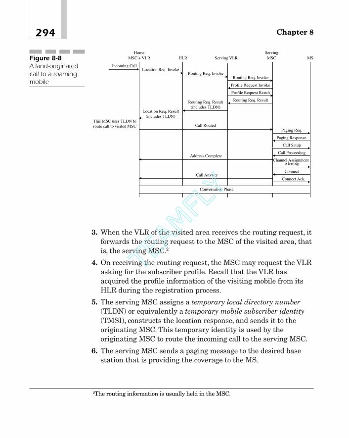
3. When the VLR of the visited area receives the routing request, itforwards the routing request to the MSC of the visited area, thatis, the serving MSC.2
4. On receiving the routing request, the MSC may request the VLRasking for the subscriber profile. Recall that the VLR hasacquired the profile information of the visiting mobile from itsHLR during the registration process.
5. The serving MSC assigns a temporary local directory number(TLDN) or equivalently a temporary mobile subscriber identity(TMSI), constructs the location response, and sends it to theoriginating MSC. This temporary identity is used by theoriginating MSC to route the incoming call to the serving MSC.
6. The serving MSC sends a paging message to the desired basestation that is providing the coverage to the MS.
Chapter 8294
HomeMSC + VLR HLR
ServingMSCServing VLR MS
Profile Request Invoke
Profile Request Result
Incoming CallLocation Req. Invoke
Routing Req. InvokeRouting Req. Invoke
Routing Req. ResultRouting Req. Result(includes TLDN)
Location Req. Result(includes TLDN)
This MSC uses TLDN toroute call to visited MSC Call Routed
Paging Req.
Paging Response.
Call Setup
Call ProceedingAddress Complete
Channel Assignment ,Alerting
Connect
Connect Ack.
Conversation Phase
Call Answer
Figure 8-8A land-originatedcall to a roamingmobile
2The routing information is usually held in the MSC.
TEAMFLY
Team-Fly®
7. The base station pages the mobile.
8. The MS sends a page response message to the base station.
9. The serving MSC presents a call setup message to the mobile,which confirms it by sending a call proceeding message,whereupon the serving MSC sends an SS7 address complete tothe originating MSC.
10. The serving MSC requests the base station to assign a trafficchannel.
11. The MS sends an acknowledgment to the base station, whichrelays it to the serving MSC, indicating that the channelassignment is completed (not shown).
12. The mobile is alerted.
13. The mobile station goes off-hook and sends a connect message tothe base station indicating that a connection has beenestablished. This message is relayed to the serving MSC, whichthen replies back with an SS7 answer message. The conversationmay now begin.
SummaryA general, high-level concept of call controls and mobility manage-ment in wireless networks has been presented in this chapter. Callcontrols are concerned with signaling procedures required to estab-lish or tear down a call. MM refers to location updates and locationreporting, registration of MSs, and authentication. The protocolstacks at a few reference points in the access and core networks havebeen briefly described. RANAP provides signaling between aUTRAN and the core network. Functions performed by this protocoland messages required to assign radio channels when a call is initi-ated or when an MS visits another system are described. The chap-ter concludes with some simple call control scenarios.
295Call Controls and Mobility Management

References[1] 3G TS 25.301, “Radio Interface Protocol Architecture,” 1999.
[2] ETSI TS 125 401 (3GPP TS 25.401 Version 3.5.0), UTRANOverall Description, 2000.
[3] ETSI TS 125 410 (3GPP TS 25.410 Version 3.3.0), UTRAN IuInterface, General Aspects and Principles, 2000.
[4] ETSI TS 125 411 (3GPP TS 25.411 Version 3.3.0), UTRAN IuInterface Layer 1, 2000.
[5] ETSI TS 125 412 (3GPP TS 25.412 Version 3.6.0), UTRAN IuInterface Signaling Transport, 2000.
[6] ETSI TS 125 413 (3GPP TS 25.413 Version 3.4.0), UTRAN IuInterface RANAP Signaling, 2000.
[7] ETSI TS 125 414 (3GPP TS 25.414 Version 3.6.0), UTRAN IuInterface Data Transport and Transport Signaling, 2000.
[8] ETSI TS 125 415 (3GPP TS 25.415 Version 3.5.0), UTRAN IuInterface User Plane Protocols, 2000.
[9] M. Pautet and M. Mouly, “GSM Protocol Architecture: RadioSub-System Signaling,” IEEE Veh. Technol. Conf., 1991.
[10] ANSI T1.111-1988: Signaling System No. 7 (SS7)—MessageTransfer Part (MTP).
[11] ANSI T1.112-1988: Signaling System No. 7 (SS7)—SignalingConnection Control Part (SCCP).
[12] ANSI T1.114-1988: Signaling System No. 7 (SS7)—Transac-tion Capabilities Application Part (TCAP).
[13] M.R. Karim, ATM Technology and Services Deliver. New Jer-sey: Prentice Hall, 2000.
[14] EIA/TIA IS-41.1—41.5, Cellular Radio-TelecommunicationsIntersystem Operations, December 1991.
[15] TIA IS-634, MSC-BS Interface for 800 MHz, 1995.
Chapter 8296

Quality of Service (QoS)in 3G Systems
CHAPTER 99
Copyright 2002 M.R. Karim and Lucent Technologies. Click Here for Terms of Use.

IntroductionThe Internet was originally designed for nonreal-time data servicessuch as interactive burst or interactive bulk transfer. In these appli-cations, there are no requirements on the maximum amount ofdelays that a packet may encounter during its transit to the desti-nation. Similarly, bandwidths required by an end user are neverspecified. As such, the network accepts all incoming packets withoutusing any admission control mechanism, forwards them using a sim-ple, first-come-first-served algorithm, and delivers them on a best-effort basis.1 Thus, issues concerning the quality of service (QoS)delivered to an end user are rather straightforward. The QoS in pre-sent-day mobile IP is also minimal because, once again, data is deliv-ered using the best-effort scheme. With the emergence of real-timemultimedia services as envisaged by third-generation (3G) wirelesssystems, new QoS requirements are imposed on the networks. Forexample, with interactive video conferencing or streaming video andaudio, the network must be able to deliver these services to the des-tination on a timely basis. Because flow control or retransmission isnot possible for these applications, the bit error rate or packet lossratio must be kept below a certain level; otherwise, the QoS may suf-fer. For instance, if the bit error rate is too high, the video in anMPEG application may never synchronize at a receiver.2
The Internet Engineering Task Force (IETF) is developing stan-dards that provide QoS in an IP network. To this end, it has definedtwo models. One of them, called integrated services (IntServ), allowsa receiving terminal (or host) to reserve network resources along aroute to the sender [3]. The traffic coming into a node from each useris classified on the basis of its characteristics, and resources arereserved explicitly on an end-to-end basis for each flow (that is, asequence of packets between any sending and receiving application).
Chapter 9298
1In other words, the network delivers as many packets with as little delays as possi-ble within the constraint of its resources.2Similarly, the IP and User Datagram Protocol (UDP) alone are not adequate for thesereal-time applications.The Real-time Transport Protocol (RTP) [6], which works abovethe UDP layer and allows for the identification of payload types, sequence-numbering,time-stamping, and so on, has been designed specifically for these services.

This reservation is made using the Resource Reservation Protocol(RSVP) defined by the IETF for real-time services over virtual cir-cuits [1], [2]. The other model is known as differentiated services(DiffServ). It divides incoming traffic (from any user) into a fewclasses [14]. For example, one class of traffic may require the net-work to assign the associated packets the highest priority and there-fore forward them first. Another traffic class may be such thatassociated packets can wait a while before they are forwarded to thenext hop, but in the event of congestion, they must be dropped lastand so on. In DiffServ, unlike IntServ, the receiving end point doesnot make any explicit reservation of network resources.
QoS concepts and issues as they relate to ATM, frame relay, andIP-based networks have been extensively studied by many authors[6], [7]. Concepts and QoS architectures germane to 3G cellular net-works have been published in [9], [10]. In providing QoS, we are onlyconcerned with the UTRAN (that is, the radio link) and the corenetwork (that is, the routers), and not the entire networks from oneend to the other. In other words, referring to Figure 9-1, the QoS con-cepts and procedures developed by 3G only apply to the UMTS radiobearer service. The objective of this chapter is to provide the readerwith a basic understanding of the subject.
299Quality of Service (QoS) in 3G Systems
Figure 9-1Provision of QoS in3G networks

The organization of this chapter is as follows. It begins with anoverview of how QoS is usually implemented following the IntServmodel. To request and provide the desired QoS, it is necessary toclassify the traffic emitted by a source and characterize the servicerequested by a user. These topics are discussed in sections 3 and 4,respectively. A brief description of RSVP is provided in section 5.Admission control and servicing strategies that ensure therequested QoS are presented in sections 6 and 7. Section 8 gives ashort description of the DiffServ model and indicates how IntServand DiffServ regions can be connected together in an attempt tocombine the features of the two models. The chapter concludes witha discussion of how a 3G network can provide QoS to a mobile sta-tion as it is handed over from one cell to another in the same servingarea, or from one serving area to another.
Overview of the ConceptsIn the IntServ model, there are actually four aspects to the QoSissues. This is shown in Figure 9-2. First, the network must bedesigned so as to provide a means for the user application to requestthe QoS desired. Second, once the network receives the servicerequest, it should be able to analyze the request, determine the net-work resources (such as the bandwidth, buffers, spreading codes,error-detecting codes, algorithms, and so on) required to provide therequested quality, and admit the user only if it is authorized to receivethe service or request the QoS, and, at the same time, the network hasenough resources.Third, the network must now set aside the requiredresources for the incoming user and mark packets that should receivethe requested quality. Finally, the network must be able to police andenforce the service contract of each user by monitoring traffic rates,inform any user that violates its traffic contract, and take appropriateaction to prevent congestion in the network so that the packet lossratio is within the advertised limits of the system. If incoming pack-ets meet their service contract, the network must forward themtowards their destination, still guaranteeing the requested quality.Otherwise, it may send the packets on a best-effort basis.
Chapter 9300

Classification of TrafficOne of the distinctive features of a 3G system is its capability to pro-vide different services such as video conferencing, real-time processcontrol and telemetry, streaming audio and video, high-speed datatransfers, and so on. More specifically, it is required to support datarates of at least 384 kb/s in urban or suburban areas, 144 kb/s in ruralareas, and up to 2.048 Mb/s in indoor or limited-range, outdoor envi-ronments. Because, in a general case, a mobile station may run sev-eral applications simultaneously, it is necessary to characterize thetraffic in some meaningful way so that each application can requestthe desired QoS from the network in a straightforward manner.
One way to classify the user traffic is based upon how the networkshould assign its resources, say, bandwidth, to transport that trafficacross the network. For example, some traffic, such as video tele-phony or voice over IP (VoIP), requires the bandwidth to be allocatedat regular intervals, whereas no such regular allocation is necessaryfor nonreal-time, delay-insensitive data. On the basis of this require-ment, then, the following types of traffic are possible:
301Quality of Service (QoS) in 3G Systems
Figure 9-2Functions involvedin providing QoS

� Constant bit rate (CBR) traffic Sensitive to delays, this type oftraffic generates fixed-size packets on a periodic basis. Examplesare speech, high-quality audio, video telephony, full-motionvideo, and so on. Here, each individual application knows theamount of bandwidth it requires for the duration of the call andmay use it to request the QoS.
� Real-time variable bit rate (VBR) traffic This traffic generatesvariable-size packets on a periodic basis. Examples includevariable bit-rate encoded audio, interactive video encoded into anMPEG standard, and so on. In this case, it is not possible for theapplication to know the exact bandwidth it needs. However, itmay have the knowledge about the sustainable traffic rate,maximum traffic rate, and maximum traffic burst. Thesustainable traffic rate may be defined as the maximum amountof traffic per unit time that the network has agreed to carry overtime. The phrase over time is important because although thenetwork can carry a much larger traffic load for a relatively shortinterval, the user traffic should be within this value most of thetime. That being the case, the sustainable traffic rate can equalbut never exceed the access rate, that is, the transmission rate ofthe physical medium. Similarly, if multiple logical channels aredefined on a physical channel, the sum of the sustainable trafficrates of all these channels cannot exceed the access rate.
The maximum traffic rate is not meaningful unless we alsodefine the maximum burst size. As an example, suppose that theaccess rate on a physical channel is 64 kb/s (that is, themaximum bit rate), and the sustainable traffic rate is 32 kb/s.The user could also specify to the network that it would emittraffic at a rate of 64 kb/s for, say, 100 ms every second. At othertimes, it agrees to keep its traffic rate below 32 kb/s so that overtime the sustainable traffic rate would be around 32 kb/s assubscribed by the user.3 Because there may be many logicalchannels defined on a single physical channel, the sum of thepeak traffic rates may well exceed the access rate. In this case,
Chapter 9302
3To be precise, the source would emit 25.6 kb over the next 0.9 s.

the network may congest during these peak traffic times anddrop excess packets unless it has sufficient buffers to hold theincoming burst. Because the network has limited buffers, it isnecessary for it to know the burst size so that it can allocate abuffer of appropriate size.
With the specification of these parameters, the network mayallocate the maximum amount of bandwidth on a regular basisto ensure that packets of all sizes would be able to get through.Or, better yet, the network may measure the input traffic and,using past allocation, predict the required number of slots sothat the frame error rate is within the limits specified by theuser.
� Nonreal-time variable bit rate traffic This type of traffic cantolerate delays or delay variations. An example is an interactiveand large file transfer service. The source may indicate to thenetwork its minimum sustained traffic rate and the maximumtolerable delay between successive transfers. If the source doesnot specify any of these parameters, the network may, in theevent of congestion, reduce its bandwidth allocation.The traffic may also be classified according to the extent to which
it can tolerate end-to-end delays and delay variations. Based on thiscriterion, Reference [9] lists the following types of traffic:
� Real-time conversational traffic This real-time traffic is bi-directional, involving human users at the two ends of acommunication link, and is characterized by low end-to-enddelays. Since the perceptual quality of the received signalgreatly depends on how well the silent or inactive periodsbetween adjacent information entities are preserved, delayvariations should also be kept very small (about 1 ms or less).Applications that fall in this category are conversational voice,video phone, and video conferencing. Also belonging to thiscategory, but with somewhat less stringent requirements on thetransfer delay, are interactive games and two-way processcontrol and telemetry information.
� Interactive traffic This class of traffic, which involves manand machine, is based on a request/response from end-points.
303Quality of Service (QoS) in 3G Systems
It is nonreal-time and may be unidirectional or bidirectional.Examples are web browsing, e-mail, data transfer to or from aserver, transaction services (that is, e-commerce), and so on.Because applications generating this traffic are nonreal-time,delays may be longer but usually have an upper limit.However, payload contents of protocol data units (PDUs) mustbe transferred without any modification and with low bit errorrates. Delay variations must be kept very small (1 ms or less).
� Streaming traffic This traffic is associated with real-timeapplications. However, unlike the conversational type, it isunidirectional (between man and machine) and has asomewhat more continuous flow with fewer and shorterinactive/silent periods between information entities. Becausethe traffic is unidirectional, end-to-end transfer delays may belarge as long as their variations are small (1 ms or less).Examples are audio streaming, one-way video, still images,large-volume data transfers, and telemetering information formonitoring purposes at an operations and maintenance center.
� Background traffic As the name implies, the data transfer forthis kind of traffic takes place in the background only when thecomputer has some real-time left after finishing high-prioritytasks. Because there is no requirement on when it shouldarrive at the destination, permissible delays or delay variationsare not specified. Bit error rates, however, must be very low andPDU contents must be preserved. Applications giving rise tothis traffic have usually low priorities. For example, the shortmessaging service (SMS) in GSM, or the delivery of e-mailsfrom one server to another, falls in this category.
UMTS Service AttributesIn 3G, the term service attributes means services provided by thenetwork. As such, the traffic type may be considered a serviceattribute. For example, when requesting a QoS, a mobile station mayspecify the traffic class to be conversational voice. The network maythen use it as a basis for scheduling necessary resources to meet the
Chapter 9304
TEAMFLY
Team-Fly®

quality of that class of traffic. Some of the service attributes in 3Gare listed below [10]:
� Guaranteed bit rate It is given by the number of bitsguaranteed to be delivered by the UMTS per unit time over theduration of a call. It must be at least equal to the sustainable bitrate, which is equal to the number of bits/second averaged overthe life of a call.
� Burst size A burst is said to have occurred when two or morepackets appear in quick succession such that the associatedminimum interarrival times are less than the packet arrivaltime averaged over the duration of a call. The number of bits inthe burst is called the burst size. The term maximum servicedata unit (SDU) size used in the UMTS literature may beconsidered as equivalent to the burst size. Specification of theSDU format indicating possible exact sizes of SDUs enables theUTRAN to operate in the transparent radio link control (RLC)protocol mode.
� Maximum bit rate It is defined as the number of bits in a burstaveraged over the burst duration. The network may use thisparameter to select the type of coding and coding rate on adownlink channel on the radio interface.
For the definition of these parameters, see Figure 9-3. Assumingthat we have t1 t2 t3 t4, the four packets appearing in timeperiod Tb form a burst because their interarrival time t1 is theshortest. If T, the duration of the call, is large compared to t1, ...,t4 and Tb, and b1, b2, ..., b7 are the packet size in bits, then thesustainable bit rate for this example is (b1 � ... � b7)/T bits/s.The burst size is b1 � b2 � b3 � b4, and the peak traffic rate is (b1 � b2 � b3 � b4)/Tb.
� Delays and delay variations A packet may encounter delays ata number of points as it travels from the source to thedestination. They include:� Propagation delays.� Delays due to buffering at an input or output port.� Serialization delay.
305Quality of Service (QoS) in 3G Systems

� Switching delays. This component increases with the numberof nodes in a network.
Delays in packet-switched networks are not constant but varybecause incoming packets arrive at input ports randomly andare processed according to some priority queuing schemes.Furthermore, each packet may be treated differently forforwarding purposes. For example, packets with the samedestination address may be forwarded along different routes atdifferent instants during the life of a call depending upon thepriority of each packet and the incoming traffic volume at anode.
Real-time conversational traffic (such as voice, video telephony,and so on) is sensitive to delays and delay variations (that is,jitter). For instance, round-trip delays of 600 ms or more, evenwith echo cancellers, may cause confusion on the part of listenersand may even cause both parties to talk simultaneously. Butdelays in the range of 100 ms or so may not have any noticeableeffect on the perceptual quality of speech. On the other hand, thehuman ear is extremely sensitive to delay variations. Forexample, if packets of length, say, 100 ms or so, are subjected tovariable delays of 10 to 170 ms, speech becomes unintelligible.
As for the interactive video, it is also sensitive to delays anddelay variations. For example, if delay variations exceed a fewtens of milliseconds, the video may not synchronize at all at thereceiving end. Because video telephony or, for that matter, one-way video also includes audio, and because the video and audiomust always be synchronized, the allowable jitter for theseapplications is generally quite low.
3G system requirements specify that the maximum transferdelay must lie in the range of 20 to 300 ms with little or no jitter
Chapter 9306
Figure 9-3Definition ofsustainable trafficrate, burst size, andpeak traffic rate

for all real-time applications in urban or suburban outdoorenvironments at velocities up to 120 km/h, rural outdoor atspeeds up to 500 km/h, and indoor or low-range outdoor atspeeds up to about 10 km/h. For nonreal-time applications,delays may be 1200 ms or more. As for delay variations, they aresubject to an upper limit of 1 ms. Once delays are specified,transport formats on various transport channels can be defined.
� SDU error ratio It is the ratio of SDUs either lost or received inerror to the total number of SDUs. The UTRAN can use thisparameter to select protocols, error-detecting codes, algorithms,and so on.
� Residual bit error ratio It is defined as the undetected bit errorratio in the delivered SDUs and may be used to select protocolsand error-detecting codes.
� Bit error rate Actually, bit error rates are not considered to beservice attributes in UMTS. However, an upper limit on thisparameter is sometimes specified as a desired goal. For example,in a 3G system, the maximum bit error rate is specified to be10�7 � 10�3 for real-time applications in urban, suburban, rural,indoor, and outdoor environments and 10�8 � 10�5 for nonreal-time applications.
It is worthwhile to mention here that some applications, such asfile transfers, e-mails, and so on, cannot tolerate any errors. Voiceand video traffic, on the other hand, are much more tolerant ofchannel errors. For example, with some coding schemes (such aswaveform quantizers), an acceptable speech quality is obtainedeven when the error rate is as high as 10�2. As for video, bit errorrates on the order of 10�8 or less have negligible or no effect.Error rates in the range of 10�8 � 10�3, if not corrected, will havea significant effect. If they are any higher, the system may noteven operate at all.
As indicated earlier, the recommended jitter for audio and videoregardless of the traffic type in 3G is 1 ms or less. There is nospecification of this parameter for data. Table 9-1 gives the one-way transfer delays for different media. The permissible frameerror rates for audio, video, and data of various traffic types arepresented in Table 9-2.
307Quality of Service (QoS) in 3G Systems
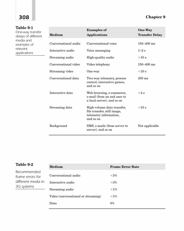
Chapter 9308
Examples of One-Way
Medium Applications Transfer Delay
Conversational audio Conversational voice 150–400 ms
Interactive audio Voice messaging 1–2 s
Streaming audio High-quality audio 10 s
Conversational video Video telephony 150–400 ms
Streaming video One-way 10 s
Conversational data Two-way telemetry, process 250 mscontrol, interactive games,and so on
Interactive data Web browsing, e-commerce, 4 se-mail (from an end user to a local server), and so on
Streaming data High-volume data transfer, 10 sfile transfer, still image,telemetry information,and so on
Background SMS, e-mails (from server to Not applicableserver), and so on
Table 9-1One-way transferdelays of differentmedia andexamples ofrelevantapplications
Medium Frame Error Rate
Conversational audio 3%
Interactive audio 3%
Streaming audio 1%
Video (conversational or streaming) 1%
Data 0%
Table 9-2
Recommendedframe errors fordifferent media in3G systems

In many instances, particularly in initial versions of 3G, a subsetof the service attributes that we discussed earlier may be adequate.Table 9-3 shows these attributes for the four traffic types. Based ona meaningful combination of these attributes, the network may cre-ate a set of profiles. For example, the network may have two profilesfor the conversational type of traffic. Profile 1 provides a maximumbit rate of 144 kb/s, a maximum SDU size of 456 bits, a guaranteedbit rate of 64 kb/s, and a transfer delay of 100 ms. Profile 2 supportsa maximum bit rate of 384 kb/s, while its remaining attributes arethe same as for profile 1.
Requesting QoS—RSVP ProtocolAs we saw before, multimedia services in 3G systems are IP-based.For IP networks, IETF has defined a resource reservation protocol,called RSVP, that enables a receiving terminal (or host) to requestthe desired QoS. This protocol operates at the transport layer aboveIPv4 [4] or IPv6 [5]. However, it does not transport user data, butrather works like the Internet Control Message Protocol (ICMP).4
309Quality of Service (QoS) in 3G Systems
Service Conversational Interactive Streaming
Attributes Type Type Type Background
Maximum x x x xbit rate
Burst size x x x x
Guaranteed x xbit rate
Delays x x
Table 9-3
Suggestedattributes for thefour traffic types
4ICMP handles error conditions that may arise when delivering an IP packet. For adescription of ICMP,TCP, and UDP, see M. Naugle, Network Protocol Handbook, NewYork: McGraw-Hill, 1994.

Because future wireless networks are also likely to be based on IP,we will present a brief overview of RSVP here.
Before describing this protocol, it is necessary to define a fewterms used in connection with RSVP. The term flow refers to a set ofpackets from the source to a destination during a session. Packetscould come to a destination from many different sources; similarly,the same source could send packets to multiple destinations. In otherwords, many-to-many multicasting is possible in RSVP. A templatespecifies the format of data packets. Mechanisms that implement aQoS for a particular data flow are called traffic control. In RSVP, thefollowing terms are called objects:
� TSPEC This object describes the traffic that is likely to begenerated by an application at the source end, and indicatessuch things as the peak rate at which the sender expects toemit, its maximum packet size, the minimum packet size thatcan be monitored (by a router), and so on. The sender’s TSPECtravels downstream (that is, towards the receiver) unchangedfrom one hop to the next until it reaches the receiver.
� RSPEC This is used by a receiving host to specify therequested level of service.
� ADSPEC This indicates the QoS requirements of the sender,expressed in terms of the bandwidth estimate, minimum pathlatency, and so on. Generated by the sending host, it travelsdownstream, and may be changed, if necessary, at anintermediate node.A reservation request includes two parameters—flowspec andfilterspec, which together are known as a flow descriptor.
� FLOWSPEC This describes the QoS requested by the receivinghost in terms of the token bucket rate, token bucket size, peakdata rate (that the receiving end-point can support), minimumpacket size, maximum packet size, and so on.5 Upon receiving
Chapter 9310
5In this characterization of the traffic, the token rate, r, is the sustainable data rateover time. The bucket size, b, indicates a data burst that may exceed the sustainablerate for a short period compared to the duration of a call. Thus, for any period t dur-ing the life of a call, the amount of data is less than r t � b.These things are explainedlater in this chapter.
the sender’s ADSPEC, the receiver may use it as a guide tochoose these parameters in its resource reservation request. Itflows upstream towards the sending host.
� FILTERSPEC This object specifies the group of packets thatare to be specially treated by the network so that they get therequested QoS. The group of packets may be selected on thebasis of some upper-layer protocol specification or on the basis ofsome header values. For example, we could say that it would beall those packets that are associated with the AddressResolution Protocol (ARP).6
RSVP defines a set of seven messages: PATH, RESV, PATHERROR, RESERVATION ERROR, PATH TEAR, RESERVATIONTEAR, and RESERVATION CONFIRMATION. The first two ofthese messages—PATH and RESV—are used in setting up a QoSreservation request.
The working of the protocol is described in the form of flow chartsin Figure 9-4. Before the receiving host initiates a resource reserva-tion request, the sending host must send a PATH message down-stream towards the receiver that should include, among otherthings, the sender’s template, TSPEC, and ADSPEC. As each routerreceives the PATH message, it may modify some parameters that arespecific to it and then forward the message to the next hop. ThePATH message follows exactly the same path as the data packets.
On receiving the PATH message, the receiving host constructs anRESV message, taking into consideration the QoS requirements ofthe sender as indicated in the PATH message as well as its owncapabilities, and sends it upstream to the nearest router. The routerchecks to see if the requesting terminal has the administrative per-mission to make the reservation. If the answer is positive, the routeranalyzes PATH and RESV messages and determines if it has enoughresources to meet the desired QoS. If it does, it assigns a service classto the user’s packets corresponding to the requested QoS, reservesnecessary resources by setting some parameters in the scheduler(such as the bandwidth on the outgoing interface, the right buffersize, priorities with which different queues are serviced, and so on),
311Quality of Service (QoS) in 3G Systems
6See the reference in footnote 4.

Chapter 9312
Figure 9-4The RSVP protocolmechanism

and then forwards the reservation request backwards to the previ-ous-hop router. This process continues until the reservation requestreaches the sending host.
Figure 9-5 shows functional entities in a router that processes aresource reservation request and subsequently provides the desiredQoS to incoming data packets. The term packet classification is usedto indicate how a particular packet is going to be treated when trans-mitting it over an outgoing link so that the requested QoS can beensured. For example, it might specify what fraction of the totalbandwidth of that link can be assigned to that packet. Similarly, ifdifferent packets are held in different queues while the outgoinginterface is busy, packet classification would indicate how the nodeshould schedule the transmission of each packet from differentqueues when the interface becomes subsequently idle.7
As user data packets come into a router from the source (oranother upstream router), the service class of each packet is exam-ined. If the associated service class matches the service class assignedin the request phase, the packet is treated for forwarding purposesusing the scheduler parameters that were previously set during thereservation request process. Otherwise, the packet is forwarded to thenext hop downstream as the best-effort or available bit rate traffic.
313Quality of Service (QoS) in 3G Systems
Figure 9-5Functional entitiesin a router or hostthat process areservation requestand subsequentlyprovide the desiredQoS to incomingdata packets
7The 3-bit precedence levels of the Type of Service field in IPv4 or the 20-bit flow labelin conjunction with the 8-bit Traffic Class field in IPv6 can be used as packet classi-fiers, which in essence is a mapping of the QoS to an appropriate number.
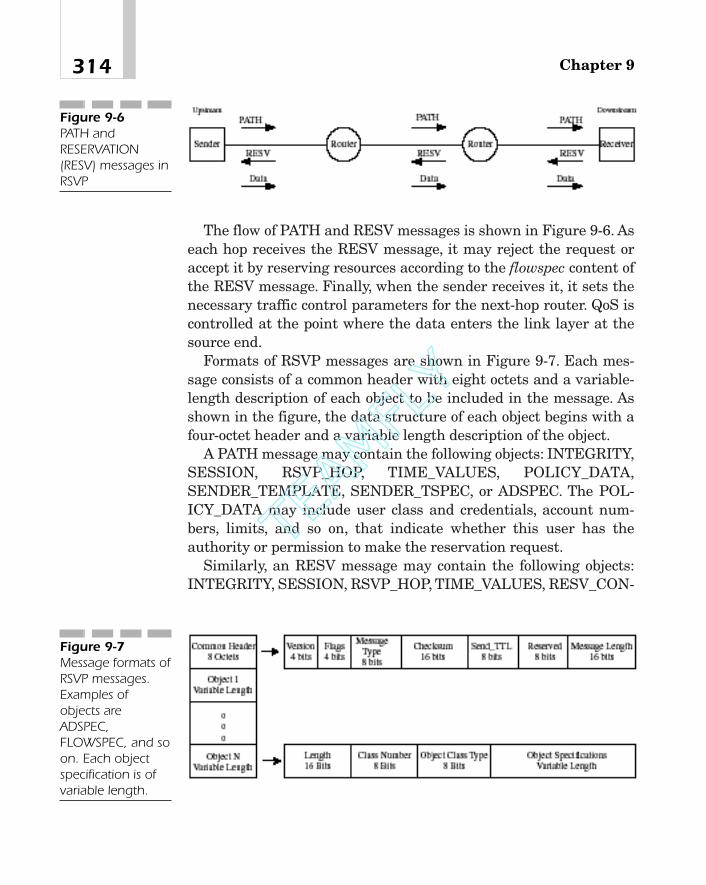
The flow of PATH and RESV messages is shown in Figure 9-6. Aseach hop receives the RESV message, it may reject the request oraccept it by reserving resources according to the flowspec content ofthe RESV message. Finally, when the sender receives it, it sets thenecessary traffic control parameters for the next-hop router. QoS iscontrolled at the point where the data enters the link layer at thesource end.
Formats of RSVP messages are shown in Figure 9-7. Each mes-sage consists of a common header with eight octets and a variable-length description of each object to be included in the message. Asshown in the figure, the data structure of each object begins with afour-octet header and a variable length description of the object.
A PATH message may contain the following objects: INTEGRITY,SESSION, RSVP_HOP, TIME_VALUES, POLICY_DATA,SENDER_TEMPLATE, SENDER_TSPEC, or ADSPEC. The POL-ICY_DATA may include user class and credentials, account num-bers, limits, and so on, that indicate whether this user has theauthority or permission to make the reservation request.
Similarly, an RESV message may contain the following objects:INTEGRITY, SESSION, RSVP_HOP, TIME_VALUES, RESV_CON-
Chapter 9314
Figure 9-6PATH andRESERVATION(RESV) messages inRSVP
Figure 9-7Message formats ofRSVP messages.Examples ofobjects areADSPEC,FLOWSPEC, and soon. Each objectspecification is ofvariable length.
TEAMFLY
Team-Fly®

FIRM, SCOPE, POLICY_DATA, STYLE, and flow descriptor list.The flow descriptor list includes the FLOWSPEC andFILTER_SPEC objects.
Admission Control
Admission Control Strategies
The idea behind admission control strategies is as follows. When auser originates a call to the network requesting a desired QoS, thenetwork must do two things before accepting the call request. First,it must make sure that it has sufficient bandwidth to allocate to thatuser. Second, it must determine if, after admitting the user, it cancontinue to provide the same QoS for all existing connections. OneQoS objective may be a desired packet loss probability. Thus, beforethe network admits the new user, it should determine whether it canmeet that packet loss probability goal for all connections, old as wellas new.
The network can proceed to do it in two ways. The simplest way isto set aside a portion of its available bandwidth that is equal to (orperhaps slightly greater than) the requested peak data rate of theincoming call and reserve that bandwidth for the duration of the call.This is possible only if the sum of the bandwidth requirements of theexisting and new connections does not exceed the total availablebandwidth. Or, considering a little more complex situation, assumethat each user provides the network with information about its traf-fic characteristics during call establishment, such as its peak andsustainable data rates. The network can now analyze the trafficusing a fixed reference model that is known as a priori, determinethe mean data rate, data rate variance, and packet loss probability,and then, based on some criteria, decide whether to admit therequesting user. Once admitted, it is allocated a fixed bandwidth.This is called the nonstatistical or fixed allocation. This controlscheme is suitable for constant bit rate services.
315Quality of Service (QoS) in 3G Systems
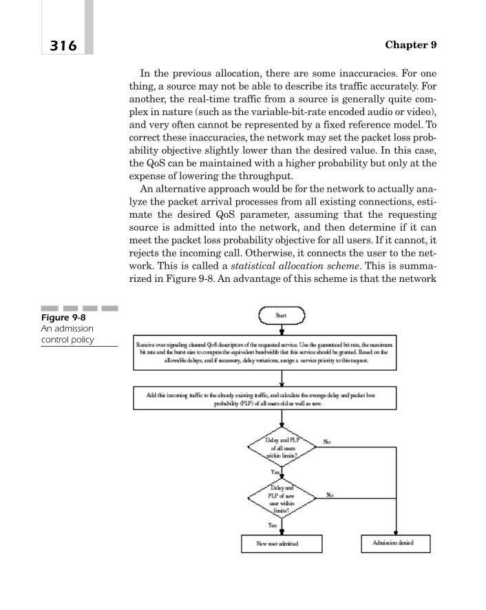
In the previous allocation, there are some inaccuracies. For onething, a source may not be able to describe its traffic accurately. Foranother, the real-time traffic from a source is generally quite com-plex in nature (such as the variable-bit-rate encoded audio or video),and very often cannot be represented by a fixed reference model. Tocorrect these inaccuracies, the network may set the packet loss prob-ability objective slightly lower than the desired value. In this case,the QoS can be maintained with a higher probability but only at theexpense of lowering the throughput.
An alternative approach would be for the network to actually ana-lyze the packet arrival processes from all existing connections, esti-mate the desired QoS parameter, assuming that the requestingsource is admitted into the network, and then determine if it canmeet the packet loss probability objective for all users. If it cannot, itrejects the incoming call. Otherwise, it connects the user to the net-work. This is called a statistical allocation scheme. This is summa-rized in Figure 9-8. An advantage of this scheme is that the network
Chapter 9316
Figure 9-8An admissioncontrol policy

can now serve more users than would be possible with the fixed allo-cation scheme. However, because the network must now do the traf-fic analysis in real-time, these schemes are generally very difficult toimplement. The problem becomes even more complex if the networkconsists of many switches over geographically dispersed areas.
Resource Allocation
Because the packet arrival process is purely random, it is often noteasy to compute the required bandwidth for an arbitrary sustainabledata rate, peak data rate, and the burst size except for very simplecases. As an example of a simple traffic pattern, consider Figure 9-9where packets arrive in bursts periodically with a period T. Eachburst contains n packets of b bits each with an interarrival time tbetween them such that t T. This represents the worst-case sit-uation because all incoming packets are treated as bursts. Assumingthe duration of each packet it is much less than t,
Then the bandwidth B required to accommodate this peak trafficrate is B � nb.8
Sustainable traffic rate R � nb>Tpeak traffic rate � b>t,
317Quality of Service (QoS) in 3G Systems
t
T
Burst withn packets
Packets
Figure 9-9An overly simplifiedtraffic pattern usedin calculatingbandwidth inadmission control
8In fact, it is shown in [8] that B � [n � R(n � 1)t]b.
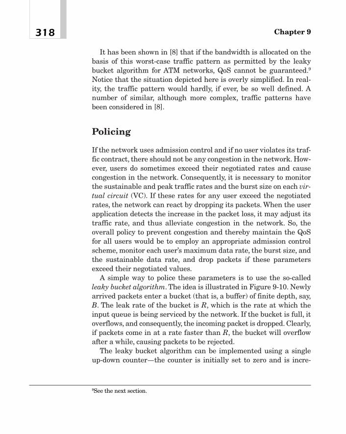
It has been shown in [8] that if the bandwidth is allocated on thebasis of this worst-case traffic pattern as permitted by the leakybucket algorithm for ATM networks, QoS cannot be guaranteed.9
Notice that the situation depicted here is overly simplified. In real-ity, the traffic pattern would hardly, if ever, be so well defined. Anumber of similar, although more complex, traffic patterns havebeen considered in [8].
Policing
If the network uses admission control and if no user violates its traf-fic contract, there should not be any congestion in the network. How-ever, users do sometimes exceed their negotiated rates and causecongestion in the network. Consequently, it is necessary to monitorthe sustainable and peak traffic rates and the burst size on each vir-tual circuit (VC). If these rates for any user exceed the negotiatedrates, the network can react by dropping its packets. When the userapplication detects the increase in the packet loss, it may adjust itstraffic rate, and thus alleviate congestion in the network. So, theoverall policy to prevent congestion and thereby maintain the QoSfor all users would be to employ an appropriate admission controlscheme, monitor each user’s maximum data rate, the burst size, andthe sustainable data rate, and drop packets if these parametersexceed their negotiated values.
A simple way to police these parameters is to use the so-calledleaky bucket algorithm. The idea is illustrated in Figure 9-10. Newlyarrived packets enter a bucket (that is, a buffer) of finite depth, say,B. The leak rate of the bucket is R, which is the rate at which theinput queue is being serviced by the network. If the bucket is full, itoverflows, and consequently, the incoming packet is dropped. Clearly,if packets come in at a rate faster than R, the bucket will overflowafter a while, causing packets to be rejected.
The leaky bucket algorithm can be implemented using a singleup-down counter—the counter is initially set to zero and is incre-
Chapter 9318
9See the next section.
mented by one each time a packet comes in and decremented by aclock of frequency R, making sure that the counter is never decre-mented below zero. When the counter reaches the maximum count,we stop incrementing the counter and mark the associated packetfor discard.
To police the maximum bit rate, it is only necessary to set thebucket depth B to 1, as shown in Figure 9-11.
To police the average bit rate or the burst size, the token bucketconcept is used. Refer to Figure 9-12. Tokens are being generated ata constant rate, say, R, and placed in a bucket that can hold, say, onlyN tokens. When a packet comes in, it must take a token to be admit-ted into the network. If there are no tokens left in the bucket, thenewly arrived packet is dropped. Clearly, if the rate of the incomingtraffic exceeds R, at some point, tokens will be exhausted, and theincoming packets will be denied access into the network. Similarly,suppose that the input source has been inactive for a while so that Ntokens have accumulated in the bucket.At this point, the source maytransmit N packets in a burst, all of which will be accepted into thenetwork. Thus, the token bucket scheme can police both the averagebit rate and the burst size (that is, the number of packets in a burst,which is N in this example).
In most cases, it is necessary to monitor both the maximum andsustainable rates. This can be done easily by means of two buckets intandem—the simple leaky bucket of Figure 9-10 for the maximum
319Quality of Service (QoS) in 3G Systems
B
IncomingPackets Packet
Overflow
Leak Rate R = Sustainable Traffic Rate
Figure 9-10Leaky bucketalgorithm tocontrol congestionby monitoring thesustainable trafficrate

rate and the token bucket for the sustainable rate. Although leakybucket algorithms are simple to implement, they can sometimes leadto inaccurate results.
Providing Requested QoSTo ensure the QoS, the network must do two things. First, it mustallocate enough bandwidth to each user based upon its trafficdescriptors, such as the peak traffic rate, the sustainable traffic rate,and the burst size. If users are admitted into the network following
Chapter 9320
1
IncomingPackets
PacketOverflow
Leak Rate R = Peak Traffic Rate
Figure 9-11Leaky bucketalgorithm to policethe peak traffic rate
N
Tokens aregenerated at
rate R
TokenOverflow
An incoming packet takes a token.
Figure 9-12The token bucketalgorithm
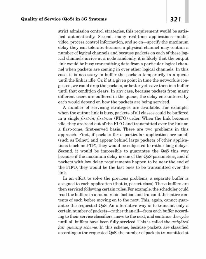
strict admission control strategies, this requirement would be satis-fied automatically. Second, many real-time applications—audio,video, process control information, and so on—specify the maximumdelay they can tolerate. Because a physical channel may contain anumber of logical channels and because packets on each of these log-ical channels arrive at a node randomly, it is likely that the outputlink would be busy transmitting data from a particular logical chan-nel when packets are coming in over other logical channels. In thiscase, it is necessary to buffer the packets temporarily in a queueuntil the link is idle. Or, if at a given point in time the network is con-gested, we could drop the packets, or better yet, save then in a bufferuntil that condition clears. In any case, because packets from manydifferent users are buffered in the queue, the delay encountered byeach would depend on how the packets are being serviced.
A number of servicing strategies are available. For example,when the output link is busy, packets of all classes could be bufferedin a single first-in, first-out (FIFO) order. When the link becomesidle, they are read out of the FIFO and transmitted over the link ona first-come, first-served basis. There are two problems in thisapproach. First, if packets for a particular application are small(such as Telnet) and appear behind large packets of other applica-tions (such as FTP), they would be subjected to rather long delays.Second, it would be impossible to guarantee the QoS this waybecause if the maximum delay is one of the QoS parameters, and ifpackets with low delay requirements happen to be near the end ofthe FIFO, they would be the last ones to be transmitted over thelink.
In an effort to solve the previous problems, a separate buffer isassigned to each application (that is, packet class). These buffers arethen serviced following certain rules. For example, the scheduler couldread the buffers in a round robin fashion and transmit the entire con-tents of each before moving on to the next. This, again, cannot guar-antee the requested QoS. An alternative way is to transmit only acertain number of packets—rather than all—from each buffer accord-ing to their service classifiers, move to the next, and continue the cycleuntil all buffers have been fully serviced. This is called the weightedfair queuing scheme. In this scheme, because packets are classifiedaccording to the requested QoS, the number of packets transmitted at
321Quality of Service (QoS) in 3G Systems
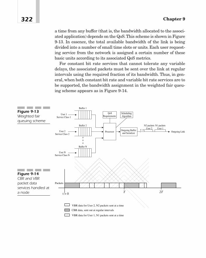
a time from any buffer (that is, the bandwidth allocated to the associ-ated application) depends on the QoS.This scheme is shown in Figure9-13. In essence, the total available bandwidth of the link is beingdivided into a number of small time slots or units. Each user request-ing service from the network is assigned a certain number of thesebasic units according to its associated QoS metrics.
For constant bit rate services that cannot tolerate any variabledelays, the associated packets must be sent over the link at regularintervals using the required fraction of its bandwidth. Thus, in gen-eral, when both constant bit rate and variable bit rate services are tobe supported, the bandwidth assignment in the weighted fair queu-ing scheme appears as in Figure 9-14.
Chapter 9322
User 1Service Class 1
User 2Service Class 2
User NService Class N
Processor Outgoing Bufferand Serializer
ooo
Buffer 1
Buffer 2
Buffer N
Outgoing Link
N1 packetsUser 1
N2 packetsUser 2o o
QoSRequirements
SchedulingAlgorithm
Figure 9-13Weighted fairqueuing scheme
t = 0
Packets
T 2T
CBR data, sent out at regular intervals
VBR data for User 1, N1 packets sent at a time
VBR data for User 2, N2 packets sent at a time
Figure 9-14CBR and VBRpacket dataservices handled ata node

Differentiated Services (DiffServ)Because in IntServ, an explicit reservation of resources is made foreach flow, the integrated services model is not suitable for a largesystem.The DiffServ model overcomes this problem by avoiding clas-sification on a per-user or per-flow basis. Instead, it differentiates theincoming packets into a small number of classes and forwardingeach packet on the basis of its class.
In DiffServ, packets are differentiated using a one-octet Differen-tiated Service (DS) field, which is actually the same as the Type ofService (TOS) field of IPv4 header [4] or the Traffic Class field ofIPv6 header [5] except for the fact that the meaning of each bit isnow redefined. The TOS field of IPv4 and the significance of its sub-fields are shown in Figure 9-15.
The DS field in DiffServ is shown in Figure 9-16. Instead of defin-ing different service types available in the network, the six-bit DScodepoint (DSCP) indicates how a collection of packets (referred to inthe RFC as a behavior aggregate) should be treated for forwardingpurposes on a per-hop basis. The forwarding treatment for a group ofpackets in the DiffServ model is termed the Per-Hop Behavior(PHB). There are many possible DSCPs and corresponding PHBs.For example, DSCP 000 000 may indicate a collection of packets thatare delivered by the network on a best-effort basis. Similarly, DSCP010 000 may be defined such that packets marked by this codepointare forwarded on a timely basis with a higher probability than pack-ets designated with, say, DSCP 001 000. Yet another DSCP may indi-cate that associated packets are to use only, say, 50 percent of thebandwidth of a shared link, and so on. Notice that the so-calleddefault PHB mapped to by DSCP 000 000 is the same as the for-warding strategy used in present-day IP routers, and thus providesfor interoperability between existing routers and a DiffServ net-work. For a detailed description of how codepoints may be mapped toPHBs, see Reference [15].
Procedures to provide QoS in DiffServ are conceptually similar tothose of IntServ that have been discussed earlier. When packets
323Quality of Service (QoS) in 3G Systems

originating from a sender enter a DiffServ network, they are classi-fied on a PHB basis and conditioned (that is, metered, shaped, andmarked) at an edge device. As packets travel downstream, the aggre-gate traffic is policed at each intermediate node in the network. Newusers are admitted only if the network capacity is not exceeded.
Chapter 9324
000
100
010
001
Delay (D),Throughput(T)
and Reliability ( R) Bits
Precedence Bits
000
001
010
011
100
101
110
111
Routine
Priority
Immediate
Flash
Flash Override
CRITICAL/ECP
Internetwork Control
Network Control
Normal Delay, Throughput and Reliability
Low Delay
High Throughput
High Reliability
(c)
(b)
(a)
Precedence3 Bits Unused
2D1
T1
R1
Figure 9-15The TOS field in the IPv4 header. (a) The field format.(b) Significance ofprecedence bits. (c) Meaning of D,T, and R bits.
TEAMFLY
Team-Fly®

Evidently, an advantage of the DiffServ model is that it lendsitself easily to a large network such as the Internet. On the otherhand, because it does not support per-user flows, it cannot provideQoS on an end-to-end basis (that is, for end users). Because anIntServ network does not scale well, but supports per-user flows, anend-to-end QoS can be delivered over any network by providingIntServ in the access part and DiffServ in the core, as shown in Fig-ure 9-17. Here, flows between two IntServ regions may be consid-ered as being transported across the DiffServ network over virtualconnections between two IntServ-capable routers [11], [16].
RSVP for Mobile SystemsProblems arise when standard RSVP is used in a mobile communi-cations network. Reference [11] has studied these problems indetail, and also summarizes the various RSVP-based protocols thathave been suggested as a possibility for wireless mobile networks.To understand these problems, consider Figure 9-18, where the cel-lular network is connected to the packet-switched public data net-work (PSPDN) via three routers—R1, R2, and R3. R2 provides
325Quality of Service (QoS) in 3G Systems
DSCP6 Bits
Unused2 Bits
Figure 9-16The DS field inDiffServ
DiffServ Network
Edge Device
End User 1 End User 2IntServ Region IntServ Region
- Routers
Figure 9-17Providing an end-to-end QoS overany network

services to cells 1–4, and R3 to cells 5–7.10 Initially, when the mobilestation (MS) is in cell 1, it reserves resources along the path shownby the thick lines from base station 1 to R2 to R1. If the MS nowmoves into cell 2, it is attached to base station 2 and makes a reser-vation along the new route from base station 2 to R2. In RSVP,because a receiving host cannot initiate a reservation request(using the RESV message) until it has received a PATH messageand because a data source sends the PATH message periodically,the MS must wait before it can make the new reservation. Mean-while, R2 continues to send packets along the old route to cell 1,
Chapter 9326
MS
Handover
PSPDNR1
R2
R3
1
2
3
4
5
PATH
RESV
6
7
Figure 9-18RSVP in a mobileenvironment
10Notice that router R1 is functionally equivalent to a Gateway GPRS Support Node(GGSN) of a GPRS or all-IP wireless network. Similarly, routers R2 and R3 corre-spond to Serving GPRS Support Nodes (SGSN).

and so these packets are lost by the MS. This problem may be some-what mitigated by modifying RSVP so that as soon as the MS ishanded over to the new cell, R2 issues a PATH message. However,since the resource reservation process is rather slow, the associateddelays may still be too long to avoid any packet loss. The problembecomes particularly severe if the MS moves into a cell where thetraffic is already quite high. In this case, the MS must renegotiatewith the network for the allocation of required resources, leading toeven longer delays and further loss of packets. And depending uponthe requested QoS, the network may not be able to guarantee thedesired quality, and consequently, may even deny the reservationrequest.
This problem can be solved if the network has some prior knowl-edge of how a mobile station is going to move around in a servingarea. Reference [12] suggests an extension of RSVP, called MobileRSVP (MRSVP), based upon this idea. In this protocol, the networkmaintains in its database a list of all nodes that are likely to be vis-ited by an MS. The MS reserves resources at all of these nodes inadvance, even though it will be using resources at only one of themat any time. In this way, delays caused by the negotiation and reser-vation of resources can be eliminated. The flow of RSVP messages inthis protocol is shown in Figure 9-19. Because the MS may visitneighboring cells 1, 2, and 3, resources are reserved along three dif-ferent routes. If the MS is located in cell 2, only the route, shown bythe heavy lines, from the MS to base station 2 to R2 through R1 tothe PSPDN is active, while the other two routes are passive.Although this protocol is conceptually simple, there are several dis-advantages:
� Although only one of the routes is active at any time, the systemmust reserve resources at many other nodes. Much of theseresources may never be used by this MS, but could have beenused by other mobile stations for a more efficient utilization ofthe bandwidth.
� An incoming call is blocked if requested resources are not avail-able at all nodes. Therefore, the call-blocking probability in-creases with the number of cells where the reservation is to bemade.
327Quality of Service (QoS) in 3G Systems

� In many instances, an MS may not know in advance exactly howit is going to roam. As such, this protocol is not very practical.
� If the number of cells that a mobile station may likely visit islarge and if there are many mobiles in a serving area, thedatabase that must be maintained by the network also becomesvery large.
Reference [13] has suggested another protocol called Mobile IPwith Location Register (MIP-LR) for mobile wireless networks.According to this protocol, when a mobile station moves into a for-eign serving area, its new location is saved in the HLR. Subse-quently, when a source node has a packet to send to this MS, itreceives the location address of the mobile from the HLR, and sendsthe packet directly to that address. However, it is still necessary to
Chapter 9328
PSPDN
R1
R2
R3
1
2
4
PATH
RESV
3
MS
Figure 9-19Reservation inMRSVP proposal
reserve resources along the new route, and packets may be lost asresources are being reserved.
SummaryIn this chapter, we have discussed QoS issues and concepts anddescribed how it can be provided in 3G UMTS networks. Providingthe QoS usually consists of four steps: requesting resources from thenetwork in accordance with a desired quality, admission control ofthe newly arrived user, resource reservation by the network, andpolicing the incoming packets to ensure that users are not violatingtheir contract. In order to request the QoS, the user must know howto characterize its traffic. With this end in view, we have classifiedthe traffic that is likely to originate in UMTS and described the traf-fic attributes that can be used to create a reasonable set of simpleQoS profiles. The RSVP protocol, admission control procedures, andpolicing schemes have been presented in some detail. Althoughmany of the ideas of the QoS that are applicable to fixed networksextend to mobile networks, standard RSVP is not quite suitable.Problems that arise when RSVP is used in a mobile network are dis-cussed. A number of protocols based on the modification and exten-sion of RSVP have been suggested. A brief description of some ofthese protocols is presented.
References[1] R. Braden, et al., “Resource Reservation Protocol (RSVP) —
Version 1 Functional Specification,” RFC 2205, September1997.
[2] J. Wroclawski, “The use of RSVP with IETF Integrated Ser-vices,” RFC 2210, September 1997.
[3] R. Braden, et al., “Integrated Services in the Internet Archi-tecture: An Overview,” RFC 1633, June 1994.
[4] Internet Protocol, RFC 791, September 1981.
329Quality of Service (QoS) in 3G Systems

[5] S. Deering, et al., “Internet Protocol, Version 6 (IPv6) Specifi-cation,” RFC 2460, December, 1998.
[6] M.R. Karim, ATM Technology and Services Delivery. New Jer-sey: Prentice Hall, 2000, pp. 87–98.
[7] D.C. Lee, Enhanced IP Services for Cisco Networks. Indiana:Cisco Press, 1999, pp. 115–177.
[8] N. Yamanaka, Y. Sato, and K. Sato, “Performance Limitationof the Leaky Bucket Algorithm for ATM Networks,” IEEETrans. Commun., Vol. 43, No. 8, August 1995, pp. 2298–2300.
[9] 3G TS 22.105 Release 1999, Services and Service Capabili-ties.
[10] 3GPP TS 23.107: QoS Concept and Architecture, Release1999.
[11] B. Moon and H. Aghvami, “RSVP Extensions for Real-TimeServices in Wireless Mobile Networks,” IEEE Commun.Mag., Vol. 39, No.12, December 2001, pp. 52–59.
[12] A.K. Talukdar, et al., “MRSVP: A Resource Reservation Pro-tocol for an Integrated Services Network with Mobile Hosts,”Dept. Comp. Sci. Tech. Rep. TR-337, Rutgers University.
[13] R. Jain, et al., “Mobile IP with Location Registers (MIP-LR),”Internet Draft, draft-jain-miplr-01.txt, July 2001.
[14] S. Blake, et al., “An Architecture for Differentiated Services,”RFC 2475, December 1998.
[15] K. Nicholas, et al., “Definition of the Differentiated ServicesField (DS Field) in the IPv4 and IPv6 Headers,” RFC 2474,December 1998.
[16] Y. Bernet et al., “A Framework for Integrated Services Oper-ation over Diffserv Networks,” RFC 2998, November 2000.
See the following web site for RFCs:
http://www.cis.ohio-state.edu/
Chapter 9330

Network Planning and
Design
CHAPTER 1010
Copyright 2002 M.R. Karim and Lucent Technologies. Click Here for Terms of Use.

The objective of network planning and design is to provide wirelesstelephony services in a serving area in the most cost-effective man-ner. In the case of an existing system, the objective is to expand andaugment its facilities so as to add new features and capabilities orincrease its capacity in case the system has reached its coveragelimit. The design usually involves determining the number of basestations and their locations that would provide the necessary cover-age in a serving area, meet the desired grade of service, and satisfythe required traffic growth so that the total startup cost is minimizedand the rate of return maximized. Clearly, if the network is wellplanned, it would be able to meet the traffic growth within the limitsof its design until a point is reached where it becomes necessary toadd new cells, assign new frequencies to an existing cell, or supple-ment the old system with a new one in a manner that is consistentwith the quality of service objectives. Because base stations are to beconnected to a mobile switching office, the design also requires thecapacity and type of the connecting links to be specified. Sometimeselements of the core network may not be able to support new ser-vices, such as high-speed multimedia applications or gateway accessto a packet data network. In these cases, the network planner mustconsider upgrading the switching systems.
The design process is roughly the following [5], [6]. Serviceproviders who want to own and operate the network generate a setof system requirements concerning the type of the desired system(such as analog, Global System for Mobile Communications [GSM],Code Division Multiple Access [CDMA], and so on), the expected traf-fic, and the desired service quality. In general, received signal-to-interference ratios and bit error rates are used as the quality ofservice indicators. Based on the above requirements, an appropriatepropagation model is used to calculate a link budget that indicatesthe maximum allowable path loss for a given transmitter power sothat the received signal-to-interference ratio at any point in the des-ignated serving area is sufficient to ensure the desired quality. Mapsand the terrain of the serving area are inspected, and assumingapproximate locations of base stations, the signal distribution overthat area is calculated.
One of the design goals is to provide coverage on the entire servingarea with a minimum number of base stations consistent with therequirement of the projected traffic growth. Currently, software tools
Chapter 10332

are available that take into consideration design requirements aswell as terrain features of the serving area, and given any number ofbase stations and their locations, they can plot the signal distributionover that area. If the coverage or the number of base stations is notoptimum, the user can alter their number and locations and run asmany iterations as necessary until the design objective is satisfied.The design might make assumptions about the maximum availabletransmitter power, commercially available transmitters types, spe-cific antenna (such as omnidirectional or sectored), their heights, andso on. It may be reviewed by engineers in consultation with the cus-tomer, modified if necessary, and when it is complete, all system com-ponents may be installed. Because the system, when actuallyinstalled, may not be exactly the same as the design (for example, theactual base station locations or their antenna heights may be slightlydifferent), it may be useful to verify the design by running some fieldtests.
System requirements fall usually into the following categories:
� The coverage area This generally involves areas to be served,e.g. counties comprised by the area. It may also be necessary toinclude information on such things as the terrain and clutter,e.g., the average height and density of buildings, streets, hills,forests, large water bodies if any, highways, populationdistribution, and so on.
� System-related requirements They should specify the following:� The technology type, indicating, for example, whether it should
be CDMA, GSM, Wideband CDMA (W-CDMA), Time DivisionMultiple Access (TDMA), cellular, and so on
� The allocated bandwidth, e.g., the number of available channelsand the number of channel sets (that is, the reuse factor)
� The type of antennas to be used (for the link budgetcalculation)
� Maximum cell size and so on� The cost objective
� The traffic This should include the following:� The number of mobile stations to be served
333Network Planning and Design
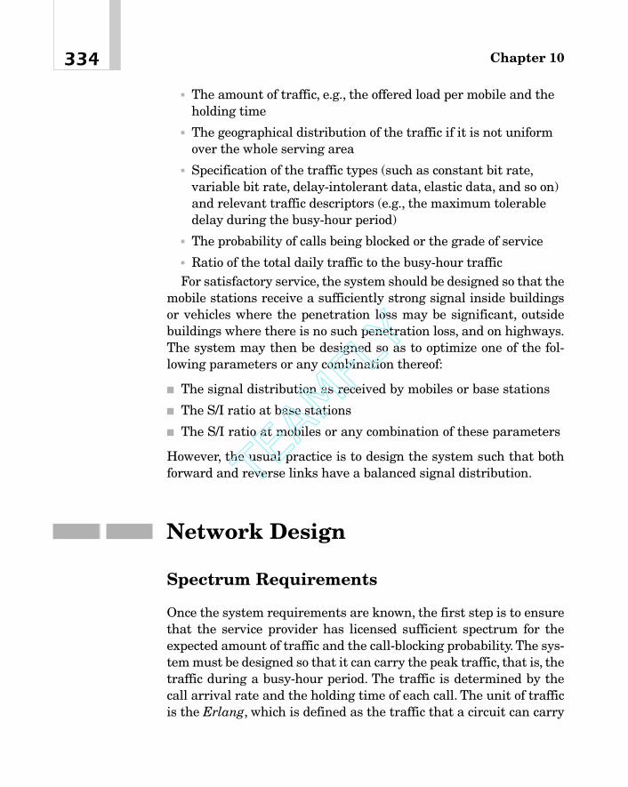
� The amount of traffic, e.g., the offered load per mobile and theholding time
� The geographical distribution of the traffic if it is not uniformover the whole serving area
� Specification of the traffic types (such as constant bit rate,variable bit rate, delay-intolerant data, elastic data, and so on)and relevant traffic descriptors (e.g., the maximum tolerabledelay during the busy-hour period)
� The probability of calls being blocked or the grade of service� Ratio of the total daily traffic to the busy-hour trafficFor satisfactory service, the system should be designed so that the
mobile stations receive a sufficiently strong signal inside buildingsor vehicles where the penetration loss may be significant, outsidebuildings where there is no such penetration loss, and on highways.The system may then be designed so as to optimize one of the fol-lowing parameters or any combination thereof:
� The signal distribution as received by mobiles or base stations
� The S/I ratio at base stations
� The S/I ratio at mobiles or any combination of these parameters
However, the usual practice is to design the system such that bothforward and reverse links have a balanced signal distribution.
Network Design
Spectrum Requirements
Once the system requirements are known, the first step is to ensurethat the service provider has licensed sufficient spectrum for theexpected amount of traffic and the call-blocking probability. The sys-tem must be designed so that it can carry the peak traffic, that is, thetraffic during a busy-hour period. The traffic is determined by thecall arrival rate and the holding time of each call. The unit of trafficis the Erlang, which is defined as the traffic that a circuit can carry
Chapter 10334
TEAMFLY
Team-Fly®
if it is utilized 100 percent of the time during a busy hour. The hold-ing time varies from applications to applications, but for telephone-type conversations during a busy hour, it lies in the range of 60 to 80seconds. The probability that a call is blocked depends on the num-ber of traffic channels (circuits) available and the total amount oftraffic coming into the network (the offered load), and is given by thewell-known Erlang B formulation. Call-blocking probabilities forvarious values of the offered load and circuits are available as tablesand graphs, where it is assumed that calls arrive at the system ran-domly with a Poisson distribution and that blocked calls are cleared;that is, when a call is blocked, it is not reinitiated [8], [9]. The trafficcapacity in Erlangs as a function of the number of circuits for a fewvalues of the call-blocking probability is given in Figure 10-7 ofAppendix A to this chapter. The determination of the bandwidth isbest explained by an example. Consider the following.
Example. Suppose that it is necessary to design a cellular systemfor 50,000 subscribers. On the average, each subscriber makes abouttwo calls during a busy hour, and the average holding time of a callis two minutes. Let us assume that the serving area is to have about14 3-sector cells and that the traffic is uniformly distributed over theentire serving area.1 If the call-blocking probability is to be 1 percent,how much bandwidth is required to provide the service?
Solution for Case 1. First, let us consider an analog system. Thetotal traffic during the busy hour � No. of Subscribers � No.Calls/hour � Holding Time in hours � 50,000 � 2 � (2/60) � 3,333.3Erlangs. So the traffic per sector of a cell � 3,333.3/(No. of Cells �No. of Sectors) � 3,333.3/(14 � 3) � 79.36 Erlangs.
The number of channels or circuits per sector required to supportthis traffic for a call-blocking probability of 1 percent (from Figure 10-7) � 95. In other words, 95 � 3 or 285 channels are needed per cell.
335Network Planning and Design
1A few comments are in order here. First of all, the traffic is rarely uniform over a serv-ing area. It generally depends on the population distribution and is much higher inurban and suburban areas, gradually decreasing toward outlying areas. Secondly, thenumber of cells is not known at the outset. In fact, given the requirements, our goal isto determine this number.
If each channel has a bandwidth of 30 kHz, the total bandwidth percell amounts to 8.55 MHz. Because seven-cell clusters are being used,the total spectrum required � 8.55 � 7 � 59.85 MHz, which is wellbeyond the spectrum allocated by the FCC to U.S. cellular systems.
In the previous example, the bandwidth required is not going to besignificantly decreased by simply increasing the call-blocking prob-ability. To be able to meet the spectrum requirements, many morecells must be used so that each cell is now smaller than before. As anexample, if the number of cells is increased to 70 and if the blockingprobability is again 1 percent, the reader can easily verify that thebandwidth required is about 15.75 MHz.
Case 2. Let us now consider a CDMA system.As in case 1, the num-ber of channels per sector for a 1 percent call-blocking probability �95. Recall that the number of simultaneous users per sector of aCDMA cell is given by
(10-1)
whereN � The number of simultaneous users per sector of a cell.Gp � Process gain. It is given by Gp � B/Rb, where B is the bandwidthand Rb is the information bit rate.Eb � Energy per bit.N0 � Spectral density of noise plus interference. Thus, Eb/N0 �
required signal-to-interference ratio.b � Interference due to mobiles in other cells transmitting on thesame channel. b is 0.85 for 3-sector cells and 0.6 for omnidirectionalones.n � Voice activity factor. The value of n is generally taken to be 0.4.
Notice first of all that equation (1) gives an upper limit on thenumber of users because it assumes that the power control of themobiles in this cell is perfect and that the interference to mobiles inany sector due to mobiles in the other two sectors is zero, assump-tions that are usually not satisfied in practice. Second, the mobilesthat are in cells other than the desired cell are not under power con-trol by the base station of this cell. So, the interference they causevaries randomly. However, because there are many of these mobiles,
N � 1 �Gp
EbN0
11 � b 2v
Chapter 10336

it is possible to consider an average value of that interference, whichin fact is being represented here by b.
A satisfactory value of Eb/N0 for speech is about 7 dB or Eb/N0 �
100.7 � 5.1. Because 3-sector cells are being used, b � 0.85. So, Gp �
(95 � 1) � (5.1) � (1.85) � (0.4) � 348.5. If the bit rate Rb � 14.4kb/s, B � 5 MHz, which is well within the realm of the allowablespectrum. Thus, it is possible to achieve a significantly higher capac-ity with the CDMA technology than with a corresponding analogsystem (or for that matter, a TDMA system).
Link Budget Calculation
The link budget calculation is fundamental to the design of cellularsystems. We shall illustrate the procedure involved by way of exam-ples.
Analog System
Example 1. Let us determine the transmitter power output PBTS ofa base transceiver station that will provide a 30 dB signal-to-noiseratio (SNR) at the baseband in an urban coverage area. The systemis assumed to be analog FM. The following parameters are assumed:
Carrier frequency 900 MHz
Base station antenna height 30 m
User Equipment (UE) antenna height 1.5 m
Distance, d, between UE and base station 2.0 km
Base station antenna gain, GBTS 9 dB
UE antenna gain, GUE 3 dB
UE receiver noise figure, NFR2 5 dB
Radio frequency (RF) bandwidth 30 kHz
Bandwidth of speech �3 kHz
337Network Planning and Design
2The receiver noise figure indicates the noise that the receiver adds, usually in its firstamplifier stage.This is in addition to the noise that comes with the signal at the inputto the receiver.
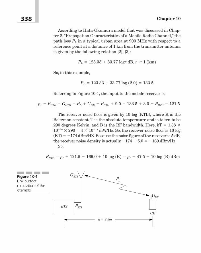
According to Hata-Okumura model that was discussed in Chap-ter 2, “Propagation Characteristics of a Mobile Radio Channel,” thepath loss PL in a typical urban area at 900 MHz with respect to areference point at a distance of 1 km from the transmitter antennais given by the following relation [2], [3]:
So, in this example,
Referring to Figure 10-1, the input to the mobile receiver is
The receiver noise floor is given by 10 log (KTB), where K is theBoltzman constant, T is the absolute temperature and is taken to be290 degrees Kelvin, and B is the RF bandwidth. Here, kT � 1.38 �10�20 � 290 � 4 � 10�18 mW/Hz. So, the receiver noise floor is 10 log(KT) � �174 dBm/HZ. Because the noise figure of the receiver is 5 dB,the receiver noise density is actually �174 � 5.0 � �169 dBm/Hz.
So,
PBTS � pr � 121.5 � 169.0 � 10 log 1B 2 � pr � 47.5 � 10 log 1B 2 dBm
pr � PBTS � GBTS � PL � GUE � PBTS � 9.0 � 133.5 � 3.0 � PBTS � 121.5
PL � 123.33 � 33.77 log 12.0 2 � 133.5
PL � 123.33 � 33.77 logr dB, r � 1 1km 2
Chapter 10338
LP
BTSP
UEG
BTSG
BTS
UE
d = 2 km
Figure 10-1Link budgetcalculation of theexample

The baseband SNR of an analog FM system depends on the aver-age value of the carrier-to-noise ratio (CNR) at the input to thereceiver and the RF channel bandwidth. Reference [1] describes howthis average CNR for any desired SNR at the baseband can be cal-culated by averaging the fading signal at the receiver input over thefading distribution. It is shown that to achieve a 30 dB SNR at thebaseband with an RF bandwidth of 30 kHz, the required CNR at thereceiver is 33.0 dB. In other words, pr � 33.0 dB. This assumes thatthe mobile velocity is about 100 km/h. So,
In this calculation, random FM has been ignored. Also, there is nodiversity in the system.
CDMA System It was shown in Chapter 2 that the local mean sig-nal level varies randomly with a log-normal distribution with astandard deviation of about 8 to 12 dB. As the mobile moves into aregion where the signal level received from another base station ishigher, it will be handed off to the new base station because the sig-nals from the two base stations are generally uncorrelated in theanalog system. In a CDMA system, when a mobile station is in a softhandoff state, there will be a 2 to 3 dB gain due to diversity com-bining. However, in some cases, signals from the two base stationsmay not be completely uncorrelated,4 and as a result, soft handoffmay not take place. Thus, for a CDMA system, a log-normal fademargin of 8 to 12 dB as well as a soft handoff gain of 2 to 3 dB shouldbe included in the link budget calculation.
It is also necessary to include a receiver interference margin tohelp avoid an overly optimistic estimate of the allowable path loss.This margin depends upon cell loading that indicates the percentageof the maximum number of users that the cell has been designed for,
PBTS � 33.0 � 47.5 � 10 log 130,000 2 � 30.27 dBm � 1.06 W.3
339Network Planning and Design
3It has been shown in Reference [1] that as the RF bandwidth is increased, the trans-mitter power required for a 30 dB SNR at the baseband first decreases, reaches a min-imum, and then begins to increase.4This is true of IS-95, which, unlike the UMTS, is a synchronous system.

who are actually using the system. Clearly, the greater the loading,the larger the interference margin should be. One way to estimatethis margin is to use the following formula:
Receiver Interference Margin � 10 log
where lf is the loading factor. As an example, suppose the capacityper sector of a 3-sector cell � 30 (users). If, on the average, only 15users are in the system, lf � 0.5 and so the receiver interference mar-gin � 3 dB. So, in this case, a fade margin of 3 dB should be used inthe link budget calculation.
In UMTS, the closed loop power control on an uplink channel takesplace at a rate of 1,500 times a second. In IS-95, this rate is 800 persecond. The fast power control can be used effectively to overcomefading, but only for slow-moving vehicles. At higher speeds, say, 120km/h or higher, the number of fades per second is significantly higher,and the average fade duration is lower than for vehicle speeds of, say,10 km/h. Consequently, the fast power control cannot compensate forfading at higher speeds.To compensate for inaccuracies in power con-trol algorithms, a fast fading margin of 2.0 to 5.0 dB should beincluded in the link budget calculation for low vehicle speeds.
Reverse Channel (Uplink) To illustrate these ideas, we will considera narrowband CDMA system and calculate the link budget for thereverse channel.
Example 2. Let us assume the following parameters:The mobile transmitter power is 250 mW � 24 dBm. The trans-
mitter antenna gain, and the cable and connector losses at themobile station will be ignored in this example.Body loss � 2 dBIn-vehicle penetration loss � 8 dBBase station receiver antenna gain � 15 dBReceiver cable loss � 1 dBReceiver noise figure � 5 dBReceiver interference margin � 3 dBInformation rate Rb � 14.4 kb/s for a 13 kb/s vocoderEb/N0 � 7 dBSoft handoff gain � 2 dB
11 � lf
Chapter 10340
Log-normal fade margin � 8 dBThe previous values of Eb/N0 and fade margin have been chosen
with a view to providing 90-percent coverage5 near cell boundariesand 96-percent coverage over an entire cell.
We are required to calculate the maximum allowable path loss.The effective radiated power of the mobile transmitter � 24 dBm
(that is, 250 mW). Suppose that the path loss from the mobile stationto the base station is PL. Then the input to the base station receiver,pin � 24 � Body Loss � Penetration Loss � Path Loss � BTSReceiver Antenna Gain � Receiver Cable Loss � 24 � 2 � 8 � PL �
15 � 1 � 28 � PL dBm.Because the receiver noise figure is 5 dB and the receiver is
required to provide an interference margin of 3 dB, the noise andinterference density of the receiver � 5 � 3 � 174 � �166 dBm/Hz.The input to the base station receiver must provide a 7 dB Eb/N0 and8 dB log-normal fade margin and must also support a data rate 14.4kb/s. So, the required input signal � �166 � 7 � 8 � 10 log (14,400)� �109.4. Because the soft handoff gain is 2 dB, the required input� �109.4 � 2 � �111.4. Therefore,
Thus, the maximum path loss is 139.4 dB.If a propagation model is known, the previous path loss can be
used to determine the maximum cell size. For example, if the basestation antenna height is 50 m, the mobile station antenna height is1.5 m and the carrier frequency 900 MHz, then following the Hata-Okumura model for a large city, the propagation loss is given by
So, for a maximum path loss of 139.4 dB, r � 2.99 km. In otherwords, the maximum cell radius is 2.99 km. This value can then be
L � 123.33 � 33.77 logr
PL � 28 � 111.4 � 139.4 dB.
pin � �111.4 dBm, or 28 � PL � �111.4; that is,
341Network Planning and Design
5Here the term coverage means the fraction of the total cell area where the QoS is sat-isfactory.
used to determine the number of cells required to provide the desiredcoverage in a serving area.
Clearly, the signal strength will be different at different pointswithin a cell depending on the terrain and clutter. However, becausenecessary margins have been included in the design, the signalstrength everywhere in the cell will be within the prescribed limit.Notice that if the requirement on the signal-to-interference ratio isrelaxed so that the QoS is slightly lowered for all users, the radius ofa cell will increase.
Forward Channel (Downlink)
W-CDMA W-CDMA supports a number of bearer services at vari-ous data rates. For example, one of them is the delay-tolerant inter-active data service (such as web browsing) or a file transfer at 384kb/s or more in urban or suburban environments for pedestrians.Consider, therefore, a W-CDMA application involving a nonreal-timedata transfer at 256 kb/s in an urban area at low vehicle speeds, say,3 to 10 km/h. Because at these speeds the level crossing rate and con-sequently the bit error rate are low, a relatively smaller value ofEb/N0 can be used for this service than for speech or real-time mulit-media applications. Even though the vehicle speed is low, a fast fad-ing margin of about 3 dB is included in the link budget.
Example 3. Assuming the following parameters, let us calculatethe maximum allowable path loss.Chip rate � 3.84 Mc/sMobile transmitter power � 24 dBmIn-vehicle penetration loss � 8 dbBase station receiver antenna gain � 16 dBReceiver cable loss � 2 dBReceiver noise figure � 5 dBReceiver interference margin � 3 dBInformation Rate Rb � 256 kb/sEb/N0 � 6 dBSoft handoff gain � 2 dBFast fading margin � 3 dBLog-normal fade margin � 8 dB
Chapter 10342

The previous values of Eb/N0 and fade margin provide 90 percentcoverage near cell boundaries and 95 percent coverage over theentire serving area.
Suppose that the path loss from the mobile station to the base sta-tion is PL. Then the input to the base station receiver pin � 24 � Pen-etration Loss � Path Loss � BTS Receiver Antenna Gain � ReceiverCable Loss � 24 � 8 � PL � 16 � 2 � 30 � PL dBm.
Noise and interference density of the receiver � Noise Figure �
Interference Margin � Noise Floor � 5 � 3 � 174 � �166 dBm/Hz.So, the required input to the receiver � �166 � Eb/N0 � Log-normalFade Margin � 10log (Rb) � �166 � 6 � 8 � 10 log (256,000) � �97.9.
So, the required input � �97.9 � Soft Handover Gain � �97.9 �2 � �99.9. Hence,
Thus, the maximum allowable path loss is 129.9 dB.
Frequency Planning
Analog and TDMA Systems
When a new analog or TDMA cellular system is being built, an obvi-ous requirement is to achieve the desired system capacity whilemaintaining a satisfactory signal-to-co-channel-interference ratioover the entire serving area with a high probability. The capacity canbe increased by decreasing the cell size. As shown in Chapter 1, thesignal-to-co-channel-interference ratio depends on the co-channelreuse ratio, D/R:
where R is the radius of a cell, D is the distance between two cellsusing the same channel set, and N is the number of cells in a cluster[4]. The assumption here is that all cells are equal in size and
DR � 23N
PL � 30 � 99.9 � 129.9 dB
pin � �99.9 dBm, or 30 � PL � �99.9; that is,
343Network Planning and Design

hexagonal in shape. A satisfactory signal-to-co-channel-interferenceratio is obtained with N � 7, in which case, D � 4.6R. This meansthat the available spectrum block is to be divided into seven sets,each of which can then be reused in other cells outside a cluster. Thiswas shown in Chapter 1 and is depicted again in Figure 10-2 for theconvenience of the reader. The numbers in the figure represent thechannel sets assigned to the individual cells. For example, theshaded cells all use channel set 2.
Another important consideration in the assignment of channels isthe adjacent channel interference. Interference from adjacent chan-nels may sometimes be serious in a mobile radio environment. Con-sider, for example, Figure 10-3 where two mobile stations, M1 andM2, are transmitting on two adjacent channels [4]. If the distance r2from mobile M2 to the base station is, say, 10 times or more greaterthan the distance r1 of mobile 1, the signal received at the base sta-tion from mobile M1 may be over 40 dB higher than the signal fromM2. Furthermore, because of fading, it is possible that the signalfrom M2 is in a deep fade while the other signal is above its localmean. Thus, even though the Intermediate Frequency (IF) filter inthe base station (or the mobile station) receiver is designed to pro-vide significant attenuation outside its bandwidth, there may beenough energy from the adjacent channel in the band of interest thatthe signal-to-adjacent-channel-interference ratio would be unac-ceptably low. Consequently, it becomes necessary to assign the chan-nels in such a way that there are no adjacent channels in the sameset. This can be done very easily in the following way. Suppose thatthere are only 21 voice channels in the available spectrum block. Thechannels may then be divided into seven sets, each with three chan-nels, using channels 1, 8, and 15 in set 1; channels 2, 9, and 16 in set2; channels 3, 10, and 17 in set 3; and so on.
Notice, however, that in the previous assignment, even though nocell contains an adjacent channel, any two adjacent cells will alwayshave some adjacent channels between them. For example, cell 1 haschannels 1, 8, and 15, and cell 2 has channels 2, 9, and 16. This situ-ation would not arise if larger clusters were used, that is, if the valueof N were, say, 12, 13, 27, and so on. However, if N � 7, and if basestations are located at the center of a cell and use omnidirectionalantennas, adjacent channels will cause interference in any cell. If, on
Chapter 10344
TEAMFLY
Team-Fly®

345Network Planning and Design
1
5
3
24
7
6
5
6
2
4
2
7
3
4
3
5
6
7
D = 4
.6 R
O
A
Figure 10-2Reuse of channelsin a cellular system.Each numberrepresents achannel set. Theco-channel reusedistance is D �4.6 R.
A
M1 r1
M2
r2
BaseStation
Figure 10-3Adjacent channelinterference
the other hand, base stations are placed at alternate corners of eachcell, and 120 degree-antenna sectors are used at each site, it is thenpossible to allocate the channels to the three sectors in a way that

will minimize the adjacent channel interference [4]. This allocationis shown in Figure 10-4 where it is assumed that there are only 21channels in the available spectrum block. Notice that adjacent chan-nels belonging to two different channel sets are assigned to sectorsfacing away from each other. For example, channel set 1 (consistingof channels 1, 8, and 15) and channel set 2 (consisting of channels 2,9, and 16) are still assigned to two cells as before, but now channels1 and 2 are assigned to sectors that face away from each othertoward different cells so that the interference to a mobile receiver incell A on channel 1, caused by, say, a base station transmitting onchannel 2 in cell B, is attenuated by the front-to-back ratio of theantenna. Thus, by simply allocating the channels to the directionalantennas in a specific way, the interference due to adjacent channelscan be reduced to a satisfactory level.
Chapter 10346
18
16
2
15 9
10
17
184
3
11
7
512
19
613
20
714
21
B
A
Figure 10-4Channel allocationthat minimizesadjacent channelinterference usingcorner cells andthree-sectordirectionalantennas

CDMA System
Because N � 1 in a CDMA system, its frequency planning is quitestraightforward.There are, however, a few things that must be takeninto consideration. For example, if a CDMA system is going to beinstalled in an area that already has another system, say, GSM, andif the spectrum blocks allocated to the two systems overlap, clearlynot all channels licensed by this service provider can be used in theCDMA base stations near the boundaries. Furthermore, if the sig-nals in either system are sufficiently strong, in order to reduce inter-ference an appropriate guard band may also have to be providedbetween the two systems. As a result, it is possible that some CDMAbase stations, particularly those at the boundary, may not have allthe channels that other base stations away from the existing systemusually have [6]. If that is the case, these base stations will not beable to provide soft and softer handoff.
The other consideration is concerned with the time offsets for theI-channel and Q-channel pilot pseudonoise (PN) sequences that areused in synchronous CDMA systems (such as IS-95 and cdma2000)to spread the forward and reverse channel transmissions. Recall thatthese PN sequences, which are maximal length shift registersequences with a period of 215 chips, are first offset in time (or phase)by an amount that is unique for each base station and then used tospread out the in-phase and quadrature components of the modula-tor output at a chip rate of 1.2288 Mc/s (or some integer multiplesthereof). Because the offsets have to be different for different sectorsin a cellular system, their allocation must be managed and coordi-nated in much the same way as the channels for cellular and TDMAsystems [5].
Cellular System GrowthIf the number of subscribers increases every year, at some point thetraffic will reach or even exceed the capacity of the system. If thathappens, the percentage of blocked calls will increase, thus leading toa degradation in the service quality. This problem can be overcome ina number of ways. For example, if there are any unused channels in
347Network Planning and Design

the available spectrum block, they may be added to the core of theserving area that experiences the highest growth in traffic. If the traf-fic is unevenly distributed over the serving area, some channels canbe taken away from the low-usage cells and assigned to the core. Foranalog and TDMA systems, another possibility is to split cells andinstall base stations at the new sites. Finally, a new system, possiblyusing a different technology, may be added as an overlay on the exist-ing system to handle the growing traffic. In fact, the new system maybe planned and designed in such a way that it carries more and moreof the traffic until eventually it serves all of the incoming traffic. Inthis case, the old system is no longer needed and may be discontinued.Obviously, there are other possibilities, but our discussion in this sec-tion is restricted to cell splitting and the overlay design only.
Cell Splitting
By cell splitting, we mean reducing the radius of coverage to half theolder value so that the coverage area is reduced by a factor of 4. Thisis achieved by installing a new base station midway between twoexisting cells [4]. See Figure 10-5. Because the number of cells isincreased four times, obviously the capacity also increases by thesame amount. Notice that it is easier to perform cell splitting whenbase stations are located at alternate corners of the cells and use120-degree directional antennas, because in that case, the hexagonalgeometry of the new cells is identical with that of the larger cells. Tosee how channel sets should be assigned to the new cell sites, observethat a new cell site is added halfway between two old co-channelcells. For example, in Figure 10-5, cell site A has been placed at amidpoint between co-channel cells 2. Consequently, cell site A mustbe assigned channel set 2. This rule is followed for assigning chan-nels to other new cells as well.
Overlay Design
When the traffic exceeds the system capacity, we could, instead ofsplitting cells, overlay a number of new, smaller cells on the existingsystem built around larger cells. When designing such a system, it is
Chapter 10348
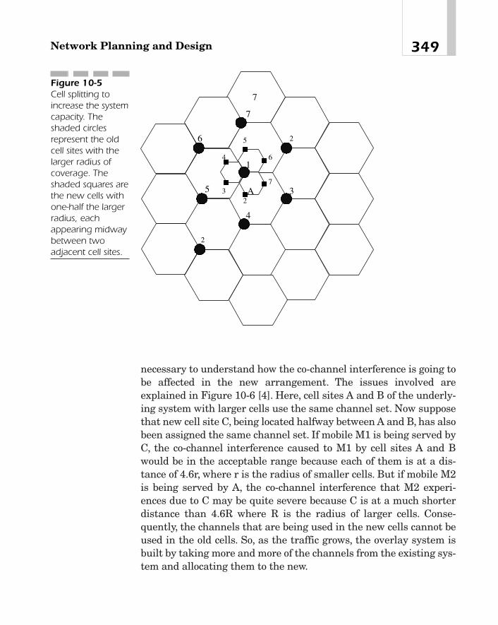
necessary to understand how the co-channel interference is going tobe affected in the new arrangement. The issues involved areexplained in Figure 10-6 [4]. Here, cell sites A and B of the underly-ing system with larger cells use the same channel set. Now supposethat new cell site C, being located halfway between A and B, has alsobeen assigned the same channel set. If mobile M1 is being served byC, the co-channel interference caused to M1 by cell sites A and Bwould be in the acceptable range because each of them is at a dis-tance of 4.6r, where r is the radius of smaller cells. But if mobile M2is being served by A, the co-channel interference that M2 experi-ences due to C may be quite severe because C is at a much shorterdistance than 4.6R where R is the radius of larger cells. Conse-quently, the channels that are being used in the new cells cannot beused in the old cells. So, as the traffic grows, the overlay system isbuilt by taking more and more of the channels from the existing sys-tem and allocating them to the new.
349Network Planning and Design
4
3
7
5
6
7
1
2
2
23
4 6
7
5
A
Figure 10-5Cell splitting toincrease the systemcapacity. Theshaded circlesrepresent the oldcell sites with thelarger radius ofcoverage. Theshaded squares arethe new cells withone-half the largerradius, eachappearing midwaybetween twoadjacent cell sites.

Reference [7] gives an elaborate example of how a CDMA systemcan be designed as an overlay on an analog system so that the por-tion of the traffic carried by the new system is gradually increased.The idea is rather simple. Initially, the entire traffic is carried by theold system. When the traffic begins to grow, a new CDMA system isbuilt with larger cells and is overlaid on the existing system. At thebeginning, only a small portion of the spectrum block, say, the equiv-alent of a few channels, is taken from the analog system and used inthe CDMA network. As the traffic increases, more and more chan-nels from the old system are assigned to the CDMA system, thusenabling it to carry a larger portion of the incoming traffic. The num-ber of channels used in the new system at any time depends on thetraffic to be carried and the call-blocking probability.
Chapter 10350
A
C
B
M1
M2
Figure 10-6Overlay of a fewsmall cells over anexisting system oflarger cells to meetincreased traffic

SummaryIn this chapter, fundamental principles of the planning and design ofa cellular network have been described. The planning begins with aset of requirements such as the total traffic, the average signal-to-interference ratio for a desired coverage criterion, the data rate, thepropagation characteristics of the serving area, the desired technol-ogy, the available spectrum, and so on. These requirements are spec-ified by the service provider. The goal of the design is to provide therequired coverage with a minimum number of cell sites. The designinvolves calculating the link budget to estimate the allowable pathloss for a given transmitter power and SNR at the receiver. Theseideas are explained using a number of numerical examples. Otheraspects of the network design include frequency planning, coordina-tion of the time offsets of the I and Q pilot PN sequences of a syn-chronous TDMA system, and cellular system growth. Frequencyplanning of a CDMA system is quite simple because the same chan-nels can be used at every base station. If there are two or more adja-cent systems in a serving area, the frequencies of the cell sites attheir boundaries must be carefully planned so as to avoid co-channeland adjacent channel interference. We have also discussed how thesystem capacity can be increased by splitting cells or overlaying anew system on an existing system without requiring any new spec-trum allocation.
Appendix A — Traffic Capacity of a NetworkSuppose that a network consists of n circuits and that calls are arriv-ing randomly so that the offered load is L Erlangs. Then, assumingthat blocked calls are not redialed into the network, the call-blockingprobability is given by the following Erlang B formula:
pb �Ln>n!
an
i�0Li>i!
351Network Planning and Design

The offered load (L) is plotted in Figure 10-7 as a function of thenumber of circuits for a few values of the call-blocking probability pb.
References[1] W.C. Jakes, Jr., “A Comparison of Specific Space Diversity
Techniques for Reduction of Fast Fading UHF Mobile RadioSystems.” IEEE Trans. Veh. Tech, Vol. VT-20, No. 4, November1971, pp. 81–92.
[2] Y. Okumura, E. Ohmori, T. Kawano, and K. Fukuda, “FieldStrength and Its Variability in VHF and UHF Land-MobileRadio Service,” Rev. Elec. Communication Lab., Vol. 16, pp.825–873, 1968.
Chapter 10352
0 10 20 30 40 50 60 70 80 90 1000
10
20
30
40
50
60
70
80
90
100
Number of Circuits, n
Inco
min
g T
raff
ic (
i.e. O
ffer
ed L
oad)
L in
Erl
angs
A
B
C
Figure 10-7Offered load inErlangs as afunction of thenumber of circuitsfor a few values ofthe call-blockingprobability pb. (A �pb � 5%, B � pb �1%, C � pb �0.1%)
[3] M. Hata, “Empirical Formula for Propagation Loss in LandMobile Radio Services,” IEEE Trans. Veh. Tech., Vol. 29, May1980.
[4] V.H. MacDonald, “The Cellular Concept,” Bell. Syst. Tech. J.,Vol. 58, No.1, January 1979, pp. 15–41.
[5] Lucent Technologies, “Personal Communication Services,CDMA RF Engineering,” Internal Publications, 1998.
[6] Lucent Technologies, “AUTOPLEX Cellular Telecommunica-tions System, System 1000, CDMA RF Engineering Guide-lines,” Internal Publications, 1998.
[7] V.K. Garg, IS-95 and cdma2000. New Jersey: Prentice Hall,2000, pp. 255–268.
[8] D. Bear, Principles of Telecommunication Traffic Engineering.London: Peter Peregrinus Ltd., 1988, pp. 236–237.
[9] R.D. Rosner, Packet Switching. Belmont, California: LifetimeLearning Publications, 1982, p. 59.
353Network Planning and Design

This page intentionally left blank.
TEAMFLY
Team-Fly®
Beyond 3G
CHAPTER 1111
Copyright 2002 M.R. Karim and Lucent Technologies. Click Here for Terms of Use.

Third-generation (3G) wireless systems have been made possible bythe concerted efforts of research and development organizations,equipment manufacturers, service providers, and above all, stan-dards bodies that took the initiative in coordinating the works ofthese organizations, harmonizing the specifications coming out ofthe laboratories, and producing a set of international standards.Many companies are now in the process of manufacturing 3G wire-less equipment so that service providers can begin to roll out 3G ser-vices to their customers in the near future. NTT DoCoMo of Japanhas been actively developing 3G technologies. Lucent Technologies ofthe United States has developed base station equipment (such as3G1X and 3G3X) that will provide 3G services for cdma2000, UMTS,and UWC-136, and is currently conducting field trials of their equip-ment with DoCoMo, Vodafone, Sprint, Bell Atlantic, AT&T, and SBC.NTT DoCoMo had targeted year 2001 for nationwide deployment ofa commercial 3G system.
Service providers, equipment manufacturers, and research labo-ratories have already begun looking beyond 3G. NTT DoCoMo isworking on their vision of the fourth-generation (4G) system, and hasstarted defining and developing 4G services and technologies [1].Many research and development projects in Europe are studyingbroadband communication issues (such as the air interface stan-dards, cell coverage characteristics, provision of the quality of service[QoS] in all IP networks, and so on) that would be relevant to 4G[2]–[5].
Driving Force Behind 4GThe demand for mobile telephone services has been phenomenal.Since the introduction of cellular telephony in 1981, the annualgrowth in the number of mobile subscribers has been about 40 per-cent, whereas telephony services over fixed networks has grown at amodest rate of about 5 to 7 percent over the same period. Most of thetraffic in present day mobile telephony consists of voice. However,the demand for mobile data has gone up steadily, spurred to a large
Chapter 11356

extent by the availability of the Internet-based applications. This isapparent from the fact that the data service capability of earlierGlobal Systems for Mobile Communications (GSMs) was limited toshort messaging service and circuit-switched data at rates of up to9.6 kb/s. As the demand for data services began to grow, the Euro-pean Telecommunications Standards Institute (ETSI) developed astandard for General Packet Radio Service (GPRS), which is nowbeing deployed in many countries of the world to provide packetmode data services at 12—20 kb/s per slot. The forecasted growth inthe voice and data traffic in mobile communications is shown in Fig-ure 11-1.1 Although the numbers are approximate, the importantthing to notice here is that the mobile data traffic is expected to bedouble the voice traffic by around 2010 and increase by a factor ofabout 24 in the year 2015. If the traffic does indeed continue to growat this rate, 2G and 3G systems may run out of capacity by that time,and so it may be necessary to consider allocating new radio spectrumto wireless communications for next generation systems.
The source of most of the traffic in the above scenario is expectedto be multimedia services. Even though there would be some appli-cations where the traffic is interactive, the data transport will beasymmetrical—the traffic downlink will be much more than theuplink traffic. In 3G, multimedia services for mobile and outdoorapplications will most likely operate at 384 kb/s. On fixed networks,video conferencing routinely uses 384 kb/s over fractional T1 lines ora primary ISDN line using bundled B channels. Many customers,currently are also using multimedia services over these networks at1.536 or 2 Mb/s. If, as is usually the case, mobile customers expect tobe provided the same services as are routinely available over fixednetworks, mobile networks will be required to support multimediaservices at 2 Mb/s. Similarly, there are applications for indoor envi-ronments, such as full-motion video, home entertainment systems,and so on that require data rates at 10—20 Mb/s. Since the maximumdata rate for fixed and indoor applications in 3G only goes up to
357Beyond 3G
1However, it is important to mention here that the past growth is no guarantee forfuture growth and that extrapolation is very speculative.

2 Mb/s, that would be another reason to consider 4G systems.Assum-ing that the 4G system is indeed a possibility, we have highlightedthe features and applications of various systems in Figure 11-2.
Applications and Features of 4GPossible applications of 4G include multimedia services for mobileenvironments (such as typical vehicular, high-speed vehicular, aero-nautical, satellite, and so on) at rates up to 2 Mb/s, compact disc(CD)-quality radio broadcasting, video surveillance of one’s homewhen travelling, full-motion video and home entertainment at ratesup to 20 Mb/s for indoor applications, position locating systems, andso on.The goal here is to provide multimedia services to anyone, any-where, anytime. The usual data rates for high-quality video are
Chapter 11358
1.0
10.0
2010
Time
Rel
ativ
e T
raff
ic
5.0
20.0
20152000
30.0
Data
Voice
Figure 11-1Growth of voiceand data traffic inmobile telephony

shown in Table 11-1, where, for comparison, ISDN and PSTN videophones have also been included.
Some of the 4G features are
� Unrestricted, seamless roaming and global mobility not only for voice, but also for data services over regional and globalnetworks that would, in all likelihood, have an all-IParchitecture.
� Interoperability between 3G and 4G and between 2G and 4G.
As for the time frame of 4G services, analog systems were intro-duced in the United States and Europe in 1981. Within 10 years,around 1991, digital systems were deployed. The 3G systems are tar-geted for introduction in 2001 and 2002. Thus, it is reasonable to
359Beyond 3G
10 kb/s
100
1.0 Mb/s
10.0
16
384
2.0
20.0
1990
2000
2010 2020GSM, IS-136
to 9.6 kb/sSMS
4GMobile data up to 2 Mb/s
Indoor up to 20 Mb/s--------------------------
Full Motion VideoHome Entertainment
MultimediaInternet Access
3GMobile data up to
384 kb/s,Indoor up to 2 Mb/s----------------------
Mobile IPMultimedia
GPRS: up to 170 kb/s
IS-95B:64 - 115 kb/s
------------------SMS, Mobile IP
Voice
Year
40.0Figure 11-2Various systemswith their servicesand applications

assume that a probable time frame for 4G would be around 2010—2012. Even though the present systems have not reached a satura-tion point, it is necessary to consider allocation of new spectrum for4G. Since it takes about three to four years to develop standards, thestandards work might begin in the next two to four years.
Technologies
Technologies that are likely to play a key role in the developmentand eventual success of 4G and, to a lesser extent, 3G are
� Software radio [6], [7] In software radio, most of the processingis done with digital signal processors. For example, basebanddata processing (such as pulse shaping, error coding, and so on),modulation and up-conversion at the transmitter, channelseparation, demodulation, detection, and baseband dataprocessing at the receiver are all performed in the digitaldomain. In addition, digital signal processing is used tocharacterize the channel and adjust the power level as needed,
Chapter 11360
Video Resolution Uncom- Com-
(pels2 � line � pressed pressed
frames/s) Bit Rate Bit Rate
Film (USA and Japan) 480 � 480 � 24 133 Mb/s 3—6 Mb/s
NTSC video 480 � 480 � 29.97 168 Mb/s 4—8 Mb/s
Phase Alternating Line 576 � 576 � 25 199 Mb/s 4—9 Mb/s(PAL) video
High-Definition Television 1920 � 1080 � 30 1493 Mb/s 18—30 Mb/s(HDTV) video
ISDN video phone 352 � 288 � 29.97 73 Mb/s 64—1920 kb/s
PSTN video phone 176 � 144 � 29.97 18 Mb/s 10—30 kb/s
2A digital image is represented by a two-dimensional array of samples. Each sample is calleda picture element (PEL) or pixel. A color image consists of red, green and blue. There are 24bits or more per sample.
Table 11-1
Data rates fordifferent types of video
analyze the received signal to determine the quality (such as thebit error rate [BER], forward error correction [FER], etc.), reduceor cancel interference from specific sources, implementmultipath diversity, and so on.
� Adaptive antenna arrays [8], [9] Adaptive antennas may beused for beam forming in a specific direction so as to provideextended coverage in certain areas or for selected mobiles andsteering nulls in the direction of co-channel cells, and so on.
� Development of suitable multimode configurable terminals,special keyboards, and video displays [10] We might considerwearable PCs with voice-activated, hands-free operation, orspecially designed keyboards that can be strapped to a wrist, andsmall LCD displays with magnifying optics attached to, orreflected onto, the user’s glasses.
� QoS For efficient utilization of bandwidth, the network mustimplement a flexible resource management scheme to providemobile stations with an end-to-end QoS across all-IP networks.Users must be able to roam seamlessly across multiple servingareas or across networks of different service providers.
� Reduced power levels Since the data rates in a 4G system aremuch higher than for 2G or 3G, the power consumption of theterminals will increase. Because an increased battery life is adesirable user feature, terminals should be designed to operateat reduced power levels.
Other Considerations
The discussion so far has been strictly from a technical point of view.Clearly, technologies already exist or are in the process of develop-ment that are necessary for successful deployment of 3G and 4G ser-vices. There is, however, an economic perspective as well. Forexample, nearly one hundred billion dollars were spent for 3Glicenses in Western Europe. In addition, a considerable amount ofcapital is needed for the 3G infrastructure. Thus, to ensure a rea-sonable rate of return from this capital investment, it is necessary togenerate sufficient customer demand for 3G services and continue touse the infrastructure for 4G and possibly beyond. For this to be pos-
361Beyond 3G

sible, it would be necessary to develop applications that are mean-ingful and attractive to customers, and at the same time commer-cially viable from the standpoint of service providers.
References[1] “The Path to 4G Mobile,” Interview with N. Nakajima, NTT
DoCoMo, IEEE Commun. Mag., Vol. 39, No. 3, March 2001,pp. 38–41.
[2] M. Dinis and J. Fernandes, “Provision of Sufficient Transmis-sion Capacity for Broadband Mobile Multimedia: A StepToward 4G,” IEEE Commun. Mag., Vol. 39, No. 8, August2001, pp. 46—54.
[3] T. Tjelta, et al., “Future Broadband Radio Access Systems forIntegrated Services with Flexible Resource Management,”IEEE Commun. Mag., Vol. 39, No. 8, August 2001, pp. 56—63.
[4] T. Robels, et al., “QoS Support for an All-IP System Beyond3G,” IEEE Commun. Mag., Vol. 39, No. 8, August 2001, pp.64—72.
[5] L. Becchetti, et al., “Enhancing IP Service Provision over Het-erogeneous Wireless Networks: A Path Toward 4G,” IEEECommun. Mag., Vol. 39, No. 8, August 2001, pp. 74—81.
[6] J. Mitola, “The Software Radio Architecture,” IEEE Commun.Mag., Vol. 33, No. 5, May 1995, pp. 26—38.
[7] R.J. Lackey and D. W. Upmal, “Speakeasy: The Military Soft-ware Radio,” IEEE Commun. Mag., Vol. 33, No. 5, May 1995,pp. 56—61.
[8] J. Kennedy, et al., “Direction Finding and ‘Smart Antennas’Using Software Radio Architectures,” IEEE Commun. Mag.,May 1995, Vol. 33, No.5, pp. 62—68.
[9] G. Tsoulos, et al., “Wireless Personal Communications for the21st Century: European Technological Advances in AdaptiveAntennas,” IEEE Commun. Mag., Sept. 1997, Vol. 35, No. 9,pp. 102—109.
[10] S. Ditlea, “The PC Goes Ready-to-Wear,” IEEE Spectrum,October 2000, pp. 34—39.
Chapter 11362
APPENDIX
List of Abbreviations and Acronyms
AAL ATM Adaptation Layer
AAL2 ATM Adaptation Layer 2
AAL5 ATM Adaptation Layer 5
AC Authentication Center
ACCH Associated Control Channel
ACELP Algebraic Code Excited Linear Prediction
ACK Acknowledgment
ADPCM Adaptive Differential Pulse Code Modulation
AGCH Access Grant Channel
AI Acquisition Indicator
AICH Acquisition Indicator Channel
AIN Advanced Intelligent Network
ALCAP Access Link Control Application Part
AMPS Advanced Mobile Phone Service
AMR Adaptive Multirate
ANSI American National Standards Institute
AP Access Preamble; Applications Processor
AP-AICH Access Preamble Acquisition Indicator Channel
ARIB The Association of Radio Industries and Business
ARP Address Resolution Protocol
ARQ Automatic Repeat Request
AS Access Stratum
ASC Access Service Class
ATM Asynchronous Transfer Mode
AUC Authentication Center
AWGN Additive White Gaussian Noise
Copyright 2002 M.R. Karim and Lucent Technologies. Click Here for Terms of Use.
BC Broadcast
BCCH Broadcast Control Channel
BCH Broadcast Channel;Bose-Chaudhuri-Hocquenghem
BCS Block Check Sequence
BER Bit Error Rate
BFSK Binary Frequency Shift Keying
B-ISDN Broadband ISDN
BLER Block Error Rate
BMC Broadcast/Multicast Control
BPSK Binary Phase Shift Keying
BS Base Station
BSC Base Station Vontroller
BSS Base Station Subsystem
BSSGP Base Station System GPRS Protocol
BSSMAP Base Station System Mobile Application Part
BTS Base Transceiver Station
CBR Constant Bit Rate
CC Call Controls
CCCH Common Control Channel
CCH Control Channel
CCITT International Telegraph and TelephoneConsultative Committee
CCPCH Common Control Physical Channel
CD/CA-ICH Collision Detection/Channel Assignment IndicatorChannel
CDMA Code Division Multiple Access
CELP Code Excited Linear Prediction
CFN Connection Frame Number
CN Core Network
CNR Carrier-to-Noise Ratio
Appendix364
TEAMFLY
Team-Fly®

CPCH Common Packet Channel
CPCS Common Part Convergence Sublayer
CPFSK Continuous Phase Frequency Shift Keying
CPICH Common Pilot Channel
CRC Cyclic Redundancy Check
CRNC Controlling Radio Network Controller
C-RNTI Cellular Radio Network Temporary ID
CS Circuit Switched
CSCF Call State Control Function
CSICH CPCH Status Indicator Channel
CTCH Common Traffic Channel
CTD Cell Transfer Delay
DCA Dynamic Channel Allocation
DCCH Dedicated Control Channel
DiffServ Differentiated Services
DL Downlink (Forward Link)
DN Directory number
DNS Domain Name System
DPCCH Dedicated Physical Control Channel
DPCH Dedicated Physical Channel
DPDCH Dedicated Physical Data Channel
DQPSK Differential Quadrature Phase Shift Keying
DRNS Drift Radio Network Subsystem
DS Differentiated Service, Direct Sequence
DS-CDMA Direct-Sequence Code Division Multiple Access
DSCH Downlink Shared Channel
DSCP Differentiated Service Code Point
DSMA-CD Digital Sense Multiple Access with CollisionDetection
DSP Digital Signal Processing
DSSS Direct-Sequence Spread Spectrum
365List of Abbreviations and Acronyms

DTAP Direct Transfer Application Part
DTCH Dedicated Traffic Channel
DTX Discontinuous Transmission
EDGE Enhanced Data Rates for GSM Evolution
EIA Electronic Industry Association
EIR Equipment Identity Register
EIRP Effective (or Equivalent) Isotropic Radiated Power
ETSI European Telecommunications StandardsInstitute
FACCH Fast Associated Control Channel
FACH Forward Access Channel
FAUSCH Fast Uplink Signaling Channel
FCCH Frequency Correction Channel
FCS Frame Check Sequence
FDD Frequency Division Duplex
FEC Forward Error Correction
FER Frame Error Rate
FIFO First In First Out
FN Frame Number
FSK Frequency Shift Keying
FTP File Transfer Protocol
GF Galois Field
GGSN Gateway GPRS support node
GMSK Gaussian Minimum Shift Keying
GP Guard Period
GPRS General Packet Radio System
GSM Global System for Mobile Communication
GSN GPRS Support Node
Appendix366

GTP GPRS Tunneling Protocol
GTP-U GPRS Tunneling Protocol in the User Plane
HCS Header Check Sequence, Hierarchical CellStructure
HLR Home Location Register
HO Handover
HSS Home Subscriber Server
ICMP Internet Control Message Protocol
IEEE Institute of Electrical and Electronic Engineers
IETF Internet Engineering Task Force
IMEI International Mobile Station Equipment Identity
IMT-2000 International Mobile Telecommunication 2000
IntServ Integrated Services
IP Internet Protocol
IPv4 IP Version 4
IPv6 IP Version 6
IS Integrated Services, Interim Standards
IS-54 Interim Standard 54 for U.S. Digital Cellular
IS-95 Interim Standard 95 for U.S. Code DivisionMultiple Access
IS-136 Interim Standard 136 for U.S. Digital Cellularwith Digital Control Channels
ISDN Integrated Services Digital Network
ISO International Standards Organization
ISP Internet Service Provider
ITU International Telecommunication Union
ITU-R ITU — Radio Communications Sector
ITU-T ITU — Telecommunications StandardizationSector
IWF Interworking Function
367List of Abbreviations and Acronyms

kb/s Kilobits per second
ksps Kilo symbols per second
LAC Link Access Control
LAN Local Area Network
LAPD Link Access Procedures on the D Channel
LLC Logical Link Control
LP Linear Prediction
LPC Linear Predictive Coding
LSA Local Service Area
LSF Line Spectral Frequency
LSN Last Sequence Number
LSP Line Spectral Pair
LTP Long Term Predictor
M3UA Message Transfer Part 3 — User Adaptation layer
MAC Medium Access Control
MAP Mobile Application Part
Mb/s Megabits per second
Mc/s Million chips per second
MER Message Error Rate
MGCF Media Gateway Control Function
MGW Media Gateway
MIP-LR Mobile IP with Location Register
MM Mobility Management
MPE Multimedia Processing Equipment
MPEG Moving Picture Experts Group
MRF Multimedia resource function
MRSVP Mobile RSVP
MS Mobile Station
MSC Mobile switching center
MSK Minimum Shift Keying
Appendix368

MT Mobile Terminal
MTP Message Transfer Part
MTP3-B Message Transfer Part Level 3 of BroadbandSignaling System 7 for Q.2140
MUD Multiuser Detection
MUI Mobile User Identifier
NACK Negative ACK
NAS Nonaccess Stratum
NMT Nordic Mobile Telephone
NNI Network-Node Interface
NS Network Service
NSAPI Network (layer) Service Access Point Identifier
NSS Network Subsystem
NTSC National Television Standards Committee
OA&M Operations, Administration, and Maintenance
ODMA Opportunity-Driven Multiple Access
OFDM Orthogonal Frequency Division Multiplexing
OMC Operations and Management Center
OQPSK Offset QPSK
OVSF Orthogonal Variable Spreading Factor
PACCH Packet Associated Control Channel
PAD Packet Assembler and Disassembler
PAGCH Packet Access Grant Channel
PBCH Packet Broadcast Channel
PC Power Control
PCCH Paging Control Channel
PCCPCH Primary Common Control Physical Channel
PCH Paging Channel
PCM Pulse Code Modulation
369List of Abbreviations and Acronyms

PCPCH Physical Common Packet Channel
PCS Personal Communications System
PCU Packet Control Unit
PDCH Packet Data Channel
PDCP Packet Data Convergence Protocol
PDN Public Data Network
PDP Packet Data Protocol (IP, X.25, etc.)
PDSCH Physical Downlink Shared Channel
PDTCH Packet Data Transfer Channel
PDU Protocol Data Unit
PHB Per-Hop Behavior
PHY Physical (Layer)
PI Paging Indicator
PICH Paging Indicator Channel
PLDCF Physical Layer-Dependent Convergence Function
PLICF Physical Layer-Independent ConvergenceFunction
PLMN Public Land Mobile Network
PLP Packet Loss Probability
PMD Physical Medium-Dependent
PN Pseudonoise
PNCH Packet Notification Channel
PPCH Packet Paging Channel
PPM Parts per million
PRACH Packet Random Access Channel;Physical Random Access Channel
PS Packet Switched
PSCH Physical Shared Channel
PSPDN Packet Switched Public Data Network
PSTN Public Switched Telephone Network
PTM Point-to-Multipoint
Appendix370
PTP Point-to-Point
PVC Permanent Virtual Circuit
QoS Quality of Service
QPSK Quadrature Phase Shift Keying
RA Routing Area
RAB Radio Access Bearer
RACH Random Access Channel
RAI Routing Area Identity
RANAP Radio Access Network Application Part
RESV Reservation (Message)
RF Radio Frequency
RFC Request for Comments
RL Radio Link
RLC Radio Link Control
RLCP Radio Link Control Protocol
RLP Radio Link Protocol
RNC Radio Network Controller
RNS Radio Network Subsystem
RNTI Radio Network Temporary Identity
RPE-LTP Regular Pulse Excitation with Long-TermPredictor
RR Radio Resources, Resource Reservation
RRC Radio Resource Control
RRM Radio Resource Management
RSM Radio Subsystem Management
RSSI Received Signal Strength Indicator
RSVP Resource Reservation Protocol
RTP Real-time Transport Protocol
371List of Abbreviations and Acronyms

SAAL-NNI Signaling ATM Adaptation Layer — NetworkNode Interface
SACCH Slow Associated Control Channel
SAP Service Access Point
SAPI Service Access Point Identifier
SAR Segmentation and Reassembly
SCCH Synchronization Control Channel
SCCP Signaling Connection Control Part
SCCPCH Secondary Common Control Physical Channel
SCH Synchronization Channel
SCP Service Control Point
SCTP Stream Control Transmission Protocol
SDCCH Stand-alone Dedicated Control Channel
SDU Service Data Unit
SF Spreading Factor; Stealing Flag
SFN System Frame Number
SGSN Serving GPRS Support Node
SIM Subscriber Identity Module
SIR Signal-to-Interference Ratio
SM Short Message
SMG Special Mobile Group
SMS Short Messaging Service
SM-SC Short Messaging Service Center
SMS-IWMSC SMS Interworking MSC
SMS-GMSC SMS Gateway MSC
SNDC Subnetwork-Dependent Convergence
SNDCP Subnetwork-Dependent Convergence Protocol
SRBP Signaling Radio Burst Protocol
SRLP Signaling Radio Link Protocol
SRNC Serving Radio Network Controller
SRNS Serving Radio Network Subsystem
SS7 Signaling System 7
Appendix372

SSCF-NNI Service-Specific Coordination Function —Network Node Interface
SSCOP Service-Specific Connection-Oriented Protocol
SSCS Service-Specific Convergence Sublayer
STP Short-Term Predictor; Signalling Transfer Point
SUF Superfield
TACS Total Access Communication System
TBF Temporary Block Flow
TC Transmission Convergence; TransactionsCapabilities
TCAP Transaction Capabilities Application Part
TCH Traffic Channel
TCP Transmission Control Protocol
TCTF Target Channel Type Field
TD-CDMA Time Division—Code Division Multiple Access
TDD Time Division Duplex
TDMA Time Division Multiple Access
TE Terminal Equipment
TF Transport Format
TFC Transport Format Combination
TFCI Transport Format Combination Indicator
TFCS Transport Format Combination Set
TFI Transport Format Indicator;Temporary Flow Identifier
TIA Telecommunications Industry Association
TLDN Temporary Local Directory Number
TMSI Temporary Mobile Subscriber Identity
TOS Type of service
TPC Transmit Power Control
TrCH Transport Channel
T-SWG Transport Signaling Gateway
373List of Abbreviations and Acronyms

TTA Telecommunications Technology Association
TTI Transmission Time Interval
TLV Type, Length, and Value
UDP User Datagram Protocol
UE User Equipment
UL Uplink (Reverse Link)
UMTS Universal Mobile Telecommunications System
UNI User-Network Interface
U-RNTI UTRAN Radio Network Temporary ID
USCH Uplink Shared Channel
USF Uplink State Flag
USIM UMTS Subscriber Identity Module
UTRA Universal Terrestrial Radio Access
UTRAN Universal Terrestrial Radio Access Network
UWC Universal Wireless Communications
UWCC Universal Wireless Communications Consortium
VBR Variable Bit Rate
VC Virtual Circuit (or Channel)
VCC Virtual Channel Connection
VCI Virtual Channel Identifier
VLR Visitor Location Register
VQ Vector Quantization
VSELP Vector Sum Excited Linear Prediction
W-CDMA Wide-band Code Division Multiple Access
WFQ Weighted Fair Queuing
Appendix374
TEAMFLY
Team-Fly®

Symbols1G network evolution, 264–2652G network evolution, 266–2672G1 network evolution, 268–2693G systems, 18
bandwidth on demand, 19bit error rate, 307cell sizes, 19commercial applications, 20data rates, 19evolution, 21mobile stations, 20network evolution, 270QoS, 19, 298radio transmitter functions, 67–68residual bit error ratio, 307SDU error ratio, 307service attributes, 304–306standards, varying types of user traffic, 20traffic classifications, 301–303UWC-136, 22wireless requirements, 262–263
4G systemsdriving development forces, 356potential applications, 358–359technologies involved, 360
8-PSK modulation, 22
AAAL-5 (ATM Adaptation Layer 5), 284AAL2 (ATM Adaptation Layer Type 2), 286access channels
cdmaOne, 123GSM, 170
access networks, GSM, signaling protocol stacks, 279
ACCH, GSM, 170ACELP speech encoders (Algebraic Code Excited
Linear Prediction), 69
adaptive antennasarrays, 361beam forming, 104
admission control, QoS, 315ADS (Automatic Dispatch Service), 3ADSPEC, RSVP, 310AGCH, GSM, 170AICH, UMTS, 213, 235ALCAP (Access Link Control Applications
Part), 286algorithms
leaky bucket, 318Viterbi, 76, 107–108
all-IP networks, 271–272Aloha scheme, 139–140, 145, 151, 170, 179, 183,
208, 214, 356amplitude variation, Rayleigh fading signals, 41AMPS (Advanced Mobile Phone Service), 8AMR speech encoders (Adaptive Multirate), 69analog systems
frequency planning, 343link budget calculation, 337spectrum requirements, 335
antennasadaptive, 104, 361directional, 102isotropic, 101narrowbeam, 102omnidirectional, 101smart, 103
applications, 4G systems, 358–359associated control channel, GSM, 170ATM (Asynchronous Transfer Mode), 283auto-correlation, PN codes, 86
Bbackground 3G traffic, 304bandwidth
cdma2000, 138cellular systems, 4
INDEX
Copyright 2002 M.R. Karim and Lucent Technologies. Click Here for Terms of Use.

on demand, 3G systems, 19UMTS, 191
BCCH, GSM, 169BCH, UMTS, 204beam forming, adaptive antennas, 104bearer services, GSM, 156behavior aggregates, DiffServ, 323BER (Bit Error Ratio), UMTS, 192BFSK (Binary Frequency Shift Keying), CDMA, 66bidirectional channels, GPRS, 182bit error rate, 3G systems, 307BMC (Broadcast/Multicast Protocol),
197, 246–247, 282BPSK (Bipolar Phase Shift Keying), 80
CDMA, 66matched filters, 91
broadcast common channel, cdma2000, 144broadcast control channels, GSM, 169BSCs (Base Station Controllers), GSM, 158BSS (Base Station Subsystem), GSM, 158BSSGP (Base Station System GPRS protocol),
GPRS, 180BSSMAP (Base Station System Mobile Application
Part), 280BTSs (Base Transceiver Stations)
GSM, 158UMTS, 202UTRAN, 194
bursts3G systems, 305GSM, 172
Ccall-blocking probability, 334capacities, CDMA, 65care-of-address, MIP-LR, 328CCH, GSM, 170CCs (Call Controls), 278
message flow, 292–295registering with system, 291–292
CDMA (Code Division Multiple Access), 13, 28BFSK (Binary Frequency Shift Keying), 66BPSK (Bipolar Phase Shift Keying), 66capacities, 65CRC codes, 67direct spread, 60excitation vectors, 70frequency planning, 347link budget calculation, 339–340LP synthesis filter, 70multipath diversity, 94
overlay designs, 350PN codes, 60, 63–64sectorized pole capacity, 65SNR, 66spectrum requirements, 336Walsh codes, 68
cdma2000, 17bandwidth, 138direct sequence spread spectrum, 21forward channels, 143, 146packet mode data services, 139protocol stack, 140–142QoS, 139reverse channels, 144, 147–148spreading, 82traffic types, 137transmit diversity, 140
cdmaOne, 13–14access channels, 123downlink, 123far-near problem, 130forward channel, 124, 127–129hard handoff, 133OQPSK modulation, 127paging channels, 123–124pilot channel, 123power control, 130–132power control groups, 125primary base stations, 133puncturing code symbols, 129reverse channel, 124–125secondary base stations, 134soft handoff, 133–136softer handoff, 134spectrum allocation, 122sync channel, 123–124traffic channels, 123uplink, 123
CDPD (Cellular Digital Packet Data), 16cell overlays, 348cell search, UMTS, 216cell sizes, 3G systems, 19cell splitting, 348Cellular System TIA-553, 9cellular systems
bandwidth, 4co-channels, 5–6, 8FDMA, 4growth issues, 347–348
channelization codes, UMTS, 227channels
encodersGSM, 163–164UMTS, 77
Index376
FDMA, 57WCDMA coding, 71
characteristic polynomials, PN codes, 88chip rates, PN codes, 60circuit switched data, GSM, 164, 173classifications of 3G traffic, 301closed loop power control, cdmaOne, 132CN (Core Network), 194CNR (Carrier-to-Noise Ratio), network
design, 339co-channels
interference, 8reuse ratio, 5–6
coherence bandwidth, 46–48coherent demodulation detection, 80commercial applications, 3G systems, 20common control channels
cdma2000, 144–145GSM, 170
common transport channels, UMTS, 204–205Compressed mode, UMTS, 230connection management, RRC, 249constant bit rate 3G traffic, 302continuous phase modulation, 161Control PDUs, RLC, 240convolutional codes
decoding, 93Viterbi algorithm, 107–108
convolutional encoders, WCDMA, 71–75core networks, GSM, signaling protocol stacks, 279coverage area, network design, 333CPCH, UMTS, 205CPFSK (Continuous-Phase Frequency Shift
Keying), 166CPICH, UMTS, 211CRC codes, CDMA, 67cross-correlation, PN codes, 86CSICH, UMTS, 213–214
DDAR systems (Digital Audio Radio), 51data rates, 3G systems, 19data services, GSM, 173DCCH, GSM, 170DCH, UMTS, 204decoding convolutional codes, 76, 93, 107–108dedicated channels
cdma2000, 143–145GSM, 170UMTS, 204
delay profiles, 47delay spreads, 47–48delay variations, 3G systems, 305–306demodulation, 80designing networks, 332
coverage area, 333frequency planning, 343–344, 347link budget calculation, 337–343spectrum requirements, 334–336system requirements, 333traffic issues, 333
differential modulation detection, 80DiffServ, 299, 323–324digital beam forming, 103Digital Cellular System, 155Direct Sequence Spread Spectrum. See DSSS.direct spread, CDMA, 60directional antennas, 102
EIRP, 30power density, 29
downlinkcdmaOne, 123, 132GPRS, 182UMTS, 226
DPCH, 210inner loop power control, 221physical channels, 210–213
DQPSK, 111Drift RNS, UTRAN, 194DS field, DiffServ, 323DSCH, UMTS, 205DSCPs (DS codepoints), DiffServ, 323DSSS (Direct Sequence Spread Spectrum), 59
CDMA 2000, 21WCDMA, 60
DTAP (Data Transfer Application Part), 281dummy burst, GSM, 173
Eearly mobile phone systems, 2–3EDGE (Enhanced Data Rates for GSM
Evolution), 22effect factors on urban received signal, 32–34EIR (Equipment Identity Register), GSM, 158EIRP (Effective Isotropic Radiated Power), 30elementary procedures, RANAP, 289environmental clutter, 31Erlang B formulation, 335Erlangs, 334
377Index
evolution of networks1G, 264–2652G, 266–2672G1, 268–2693G, 21, 270wireless, 262
excitation vectors, CDMA, 70
FFACCH, GSM, 171FACH, UMTS, 205far-near problem, cdmaOne, 130fast associated control channel, GSM, 171FAUSCH, UMTS, 206FCCH, GSM, 170FDD mode, UMTS, 190–192FDMA (Frequency Division Multiple Access), 4
channels, 57GSM, 155
features of 4G systems, 358–359FHSS (Frequency-Hopping Spread
Spectrum), 59field strength, propagaton models, 40FIFO order, QoS service, 321Filterspecs, RSVP, 310–311fingers, rake receivers, 95–96, 98fixed allocation bandwidth, admission control, 315flat fading, 46, 94flow, RSVP, 310forward channels
cdmaOne, 124, 127–129cdma2000, 143, 146
Frame Relay, GPRS, 180frames, GSM, 171frequency correction channel, GSM, 170, 173frequency planning, network design, 343–344, 347frequency-selective fading, 46, 94FSK (Frequency Shift Keying), 161full-rate speech, GSM channel encoder, 164functions of RANAP, 288fundamental channel, cdma2000, 144–145
GGaussian channel noise, demodulation, 81GPRS (General Packet Radio Service),
16, 25, 154, 174bidirectional, 182downlink channels, 182
GGSNs (Gateway GPRS Support Nodes), 177IDLE state, 183logical channels, 181network architecture, 175packet transmission protocol, 182–183packets, 180, 185PCUs (Packet Control Units), 177PDUs (Protocol Data Units), 180protocol stacks, 177–180QoS, 175READY state, 184SGSNs (Serving GPRS Support Nodes), 175STANDBY state, 184TBF (Temporary Block Flow), 183TFI (Temporary Flow Identifier), 183uplink channels, 181USF (Uplink State Flag), 183virtual circuits, 174
growth issues, cellular systems, 347–348GSM (Global System for Mobile), 12, 154
bearer services, 156BSCs (Base Station Controllers), 158BSSs (Base Station Subsystems), 158BTSs, 158bursts, 172channel encoder, 163–164data services, 173EIR (Equipment Identity Register), 158FDMA, 155frames, 171HLR (Home Location Register), 158IMEI numbers (International Mobile Station
Equipment Identity), 159interleaving, 165ISI (Inter-Symbol Interference), 168logical channels, 169–170LTP (Long-Term Predictor), 162MSK (Minimum Shift Keying), 161, 166–168MSs (Mobile Stations), 158OMC (Operations and Maintenance Center), 158punctured coding, 164RPE-LTP coders, 159signaling protocol stacks, 279–281SIMs (Subscriber Identity Modules), 157speech encoder, 162–163STP (Short-Term Predictor), 162supplementary services, 157system architecture, 155–157TDM (Time-Division Multiplexing), 155telephony, 156traffic channels, 169VLR (Visitor Location Register), 158vocoding, 155
Index378

GTP (GPRS Tunneling Protocol), GPRS, 179GTP-U (GPRS tunneling protocol), 286guaranteed bit rate, 3G systems, 305
H
Hadamard matrix, 82handoff
cdmaOne, 133IS-95 options, 134RANAP, 290
handover, RRC, 250–251hard decision, 92Hata-Okumura model, 338HCMTS (High Capacity Mobile Telecommunication
System), 4header compression, PDCP, 246HLR (Home Location Register), GSM, 158
I
ICMP (Internet Control Message Protocol), 309IDLE state, GPRS, 183Illinois Bell, first cellular system, 4IMEI numbers (International Mobile Station
Equipment Identity), GSM, 159IMT-2000 (International Mobile Telecommunication
in the year 2000), 17inner loop power control, UMTS, 219interactive 3G traffic, 304interleaving, 78
GSM, 165UMTS, 79
IntServ, 298–300IS-136 standard, 10, 22IS-1361 standard, 22IS-54 standard, 10, 58IS-95, handoff options, 134ISI (Inter-Symbol Interference), GSM, 168isotropic antennas, 29, 101
J–L
jitter, 306LAPD (Link Access Procedure on D
channel), 281large-scale variation, 28–30
leaky bucket algorithm, 318link budget calculation, 337–343LLC, GPRS, 178local mean signal level variation, 36–38logical channels
GPRS, 181GSM, 169–170
LP synthesis filter (Linear Predictor), CDMA, 70LTP (Long-Term Predictor), GSM, 162
MMAC layer (Media Access Control), 282
MAC sublayer, GPRS, 179UMTS, 232–233
PDUs, 236–237MAP (Mobile Application Part), 281matched filters, BPSK, 91maximal sequences, PN codes, 85maximum bit rate, 3G systems, 305maximum likelihood decoding, 76maximum SDU size, UMTS, 305megacells, 19messages
BMC, 247RSVP, 314
microcells, 19MIP-LR (Mobile IP with Location Register), 328MJ mobile system, 2MK system, 3MM (Mobility Management), 278mobile phone systems, early models, 2–3mobile radio channels
large-scale variation, 29–30propagation characteristics, 29–31simulation models, 49–50
mobile radio signals, 28mobile stations, 3G systems, 20mobile systems, 325–327modulation, 79
BPSK, 80DQPSK, 111MSK, 166–168OQPSK, 111QPSK, 80, 110
monitoring VC traffic, 318MRSVP (Mobile RSVP), 327MSC (Mobile Switching Center), GSM, 156MSK (Minimum Shift Keying), GSM, 161, 166–168MSs (Mobile Stations), GSM, 158MTP (Message Transfer Part), 279
379Index
MTP3-B (Message Transfer Part Level 3 ofBroadband), 284
MTS (Mobile Telephone Service), 3multimedia services, 357multipath diversity, CDMA, 94multipath reflection variation, mobile radio
signals, 28multiple access, 56, 59multiuser detection, WCDMA, 98–100
Nnarrow-beam antennas, 102networks
design, 332coverage area, 333frequency planning, 343–344, 347link budget calculation, 337–343spectrum requirements, 334–336traffic issues, 333
GPRS architecture, 175nonreal-time variable bit rate 3G traffic, 303nonstatistical bandwidth, admission control, 315normal burst, GSM, 172
Oobjects, RSVP, 310OFDM (Orthogonal Frequency Division
Multiplexing), 17OMC (Operations and Maintenance Center),
GSM, 158omnidirectional antennas, 101one-way paging, 3open loop power control, cdmaOne, 132OQPSK (offset QPSK), 111, 127OVSF codes (Orthogonal Variable Spreading
Factor), 83, 202, 224
PPACCH, GPRS, 182packets
cdma2000, mode data services, 139GPRS, 180
transfer, 185transmission protocol, 182–183
RSVP classification, 313UMTS mode data, 214
PAD (Packet Assembler and Disassembler),GSM, 156
PAGCH, GPRS, 182paging channels
cdma2000, 143cdmaOne, 123–124GSM, 170
path loss, propagaton models, 39PATH messages, RSVP, 311, 314PBCCH, GPRS, 182PCCPCH, UMTS, 211PCH
GSM, 170UMTS, 205
PCPCH, UMTS, 209PCS (Personal Communications Services), 15PCUs (Packet Control Units), GPRS, 177PDCP (Packet Data Convergence Protocol),
196, 245–246, 282PDSCH, UMTS, 213–214PDTCH, GPRS, 182PDUs (Protocol Data Units)
GPRS, 180RLC, 240–241
Phase 2+ GSM, 157PHB (Per-Hop Behavior), DiffServ, 323physical channels
cdmaOne, 123UMTS, 201, 207–210
Physical layer, UMTS, 198–199PICH, UMTS, 213picocells, 19Pilot channel, cdmaOne, 123Pilot reverse channel, cdma2000, 144planning networks, 332PN codes (pseudonoise), 59
auto-correlation, 86CDMA, 14, 60, 63–64characteristic polynomials, 88chip rates, 60cross-correlation, 86maximal sequences, 85pseudorandom output sequence pattern, 85shift register array, 84
PNCH (Packet Notification Channel), GPRS, 182Poisson distributions, 335policing
bit rates, 319burst size, 319VC traffic, 318
Index380
power controlcdmaOne, 125, 130–132UMTS, 218–219
power delay profiles, 46–48power density and antennas, 29PPCH, GPRS, 182PRACH
GPRS, 181UMTS, 208
primary base stations, cdmaOne, 133primary synchronization code, UMTS, 212propagation characteristics, mobile radio
channels, 29–31propagation models, 39–40protocol stacks
cdma2000, 140–142GPRS, 177–180UMTS, 195UTRAN, 195, 282–286
pseudorandom output sequence pattern,PN codes, 85
PSPDNs (Packet-Switched Public Data Networks),mobile system RSVP, 325
punctured codescdmaOne, 129GSM, 164WCDMA, 76
Q
QoS (Quality of Service)3G systems, 19, 298admission control, 315cdma2000, 139DiffServ, 324GPRS, 175IntServ, 300resource allocation, 317–318RSVP, 309–310servicing strategies, 320UTRAN, 299weighted fair queuing scheme, 321
QPSK, 80, 110modulation, 22receivers, 90
quick paging channel, cdma2000, 144
RRACH
GSM, 170UMTS, 205
radio frame equalization, UMTS, 201radio link setup, UMTS, 217–218radio transmitter functions, 3G systems, 67–68rake receivers, fingers, 95–98RANAP, 288, 289, 290random access channels
GSM, 170, 173UMTS, 223, 234–235
random access data transmission, UMTS, 223random FM, 28Rate Match blocks, UMTS, 201rate matching, 197Rayleigh distributions, 41Rayleigh fading signals, amplitude variation, 41READY state, GPRS, 184real-time variable bit rate 3G traffic, 302received urban signal effects, 32–34receivers, QPSK, 90relay function, GPRS, 180relocation, RANAP, 290reservation requests, RSVP, 311residual bit error ratio, 3G systems, 307resource allocation, QoS, 317–318RESV messages, RSVP, 311, 314reverse channels
cdma2000, 144, 147–148cdmaOne, 124–125
RIL 3 (Radio Interface Layer), 281RLC (Radio Link Control), 179, 237, 240–241, 282RLC sublayer, 195RNC (Radio Network Controller)
MM (Mobility Management), 278UTRAN, 193
RNS (Radio Network Subsystem), 194RPE-LTP coders, GSM, 159RR protocol, 280RRC, 248 (Radio Resource Control Protocol),
195, 247–248, 282connection management, 249handover, 250–251soft handover, 252
RSM (Radio Subsystem Management), 281RSPEC, RSVP, 310RSVP (Resource Reservation Protocol), 271, 299
ADSPEC, 310filterspec, 310–311flow, 310
381Index

flow descriptor, 310flowspec, 310message formats, 314mobile systems, 325–327objects, 310packet classification, 313PATH messages, 311, 314QoS, 309–310reservation requests, 311RESV messages, 311, 314
RSPEC, 310rural areas, signal variation, 35
SSAAL-NNI (Signaling ATM Adaptation Layer-
Network Node Interface), 284SACCH, GSM, 170SAPs (Service Access Points), 198SCCF (Service Specific Coordination
Function), 284SCCP (Signaling Connection Control Part),
280, 284SCCPCH, UMTS, 212SCH
GSM, 169UMTS, 212
scrambling codes, 83, 89, 228–230SDCCH, GSM, 170SDMA (Space-Division Multiple Access), 103SDUs (Service Data Units)
error ratio, 3G systems, 307UMTS, 305
secondary base stations, cdmaOne, 134sectorized pole capacity, CDMA, 65service attributes of 3G systems, 304–306servicing strategies, QoS, 320Serving RNS, UTRAN, 194SGSNs (Serving GPRS Support Nodes),
GPRS, 175shift register array, PN codes, 84short-term signal variation, 41, 45signaling
attenuation, 30GSM
channels, 169protocol stacks, 279–281
UMTS measurements, 230–231
variationin free space, 29local mean signal level, 36–38mobile radio signals, 28rural areas, 35short term, 41, 45
SIMs (Subscriber Identity Modules), GSM, 157simulation models, mobile radio channels, 49–50slow associated control channel, GSM, 170smart antennas, 103SMS (Short Messaging Service), 13, 174SNDCP (Subnetwork Dependent Convergence
Protocol), GPRS, 178SNR (Signal-to-Noise Ratio)
CDMA, 66network design, 337
soft decision, 92soft handoff, cdmaOne, 133–136soft handover, RRC, 252softer handoff, cdmaOne, 134software radio, 360spatial filtering, 103spectrum
cdmaOne allocation, 122requirements, network design, 334–336
speech encoder, 69GSM, 162output, 163
spread signal, UMTS, 223spread spectrum multiple access, 59spreading, 82SS7 (Signaling System 7), 279SSCOP (Service Specific Connection-Oriented
Protocol), 284stand-alone dedicated control channel, GSM, 170STANDBY state, GPRS, 184statistical allocation schemes, 316STATUS PDUs, RLC, 242STP (Short-Term Predictor), GSM, 162streaming 3G traffic, 304SUFs (Superfields), RLC, 242supplementary channels, cdma2000, 144–145supplementary services, GSM, 157survivor paths, 108Sync channel
cdma2000, 143cdmaOne, 123–124
synchronizationGSM channels, 169, 172UMTS channels, 216–217
Index382
system architectureGSM, 157network design requirements, 333
T
TBF (Temporary Block Flow), GPRS, 183TCAP (Transaction Capabilities Application
Part), 281TCH, GSM, 169TCTF (Target Channel Type Field), UMTS, 236TDD mode, UMTS, 190TDM (Time Division Multiplexing), GSM, 155TDMA (Time Division Multiple Access),
9–10, 58, 122, 343telephony, GSM, 156templates, RSVP, 310TFC (Transport Format Combination),
UMTS, 233TFCI (Transport Format Combination Indicator),
UMTS, 203TFI (Temporary Flow Identifier), GPRS, 183TFI (Transport Format Indicator), UMTS, 203THSS (Time-Hopping Spread Spectrum), 59token bucket scheme, 319TPC commands (Transmit Power Control),
UMTS, 192traffic
channelscdmaOne, 123GSM, 169
classifications, 3G systems, 301–303control, RSVP, 310network design issues, 333types, cdma2000, 137volume measurement, UMTS, 235
transmit diversity, cdma2000, 140transmit functions, cdmaOne reverse
channel, 124–125Transparent PDUs, RLC, 241transport block set, UMTS, 203transport channels, UMTS, 201–203, 215TSPEC, RSVP, 310TSUNAMI (Technology in Smart Antennas
for Universal Advanced MobileInfrastructure), 104
TTI (Transmission Time Interval), UMTS, 79, 203
UUDP (User Datagram Protocol), 271UE, (User Equipment), UMTS, 191UMTS (Universal Mobile Telecommunications
System), 18, 122, 190bandwidth allocation, 191BER (Bit Error Ratio), 192BTS, transmit functions, 202cell search procedure, 216channels
encoders, 77common transport, 204–205dedicated transport, 204downlink, 210–213, 226physical, 201, 207–210, 217random access, 223, 234–235transport, 201–203, 215uplink, 224
channelization codes, 227compressed mode, 230downlink inner loop power control, 221FDD mode, 190–192interleavers, 79link budget calculation, 340MAC layer, 232–233MAC PDUs, 236–237maximum SDU size, 305OVSF codes, 202, 224packet mode data, 214physical layer, 198–199power control, 218–219primary synchronization code, 212protocol stack, 195radio frame equalization, 201radio link setup, 217–218random access data transmissions, 223Rate Match blocks, 201scrambling codes, 89, 228–230signal measurements, 230–231spread signal, 223spreading, 82spreading factor, 60synchronization procedures, 216TDD mode, 190TFC (Transport Format Combination), 233TFCI (Transport Format Combination
Indicator), 203TFI (Transport Format Indicator), 203
383Index

TPC commands, 192traffic volume measurement, 235transport block set, 203TTI (Transmission Time Interval), 79, 203UE (User Equipment), 191uplink inner loop power control, 219–222Walsh sequences, 202
UMTS WCDMA, 56uplinks
cdmaOne, 123power control, 132
GPRS channels, 181UMTS
channels, 224DPCCH, 207inner loop power control, 219–222
urban received signal effects issues, 32–34USCH, UMTS, 206user traffic, 3G standards, 20USF (Uplink State Flag), GPRS, 183UTRA (UMTS Terrestrial Radio Access), 22UTRAN
BTSs (Base Transceiver Stations), 194Drift RNS, 194protocol stack, 195, 282–286QoS, 299RNCs (Radio Network Controllers), 193Serving RNS, 194
UWC-136 standard, 22, 56
V
VCs (Virtual Circuits)GSM, 174monitoring traffic, 318
Viterbi algorithm, 76, 107–108Viterbi decoding, 93VLR (Visitor Location Register), GSM, 158vocoders, 69, 155VoIP, bandwidth allocation, 301
W
Walsh codes, 68, 82Walsh sequences, UMTS, 202WCDMA, 191–192
channel coding, 71convolutional encoders, 71–75decoding convolutional codes, 76DSSS, 60link budget calculation, 342multiple access, 56multiuser detection, 98–100punctured codes, 76rake receivers, 95–98
weighted fair queuing scheme, QoS, 321wireless network evolution, 262
Index384
TEAMFLY
Team-Fly®