ExtremeWireless Getting Started Guide
75
ExtremeWireless ™ Getting Started Guide Release V10.11.01 9035004 Published June 2016
Transcript of ExtremeWireless Getting Started Guide

ExtremeWireless™ GettingStarted GuideRelease V10.11.01
9035004
Published June 2016

Copyright © 2016 Extreme Networks, Inc. All rights reserved.
Legal NoticeExtreme Networks, Inc. reserves the right to make changes in specifications and other informationcontained in this document and its website without prior notice. The reader should in all casesconsult representatives of Extreme Networks to determine whether any such changes have beenmade.The hardware, firmware, software or any specifications described or referred to in this documentare subject to change without notice.
TrademarksExtreme Networks and the Extreme Networks logo are trademarks or registered trademarks ofExtreme Networks, Inc. in the United States and/or other countries.All other names (including any product names) mentioned in this document are the property oftheir respective owners and may be trademarks or registered trademarks of their respectivecompanies/owners.For additional information on Extreme Networks trademarks, please see: www.extremenetworks.com/company/legal/trademarks/
SupportFor product support, including documentation, visit: www.extremenetworks.com/documentation/
For information, contact:Extreme Networks, Inc.145 Rio RoblesSan Jose, California 95134USA
Table of ContentsPreface.........................................................................................................................................4
Text Conventions...................................................................................................................................................................4Providing Feedback to Us................................................................................................................................................ 4Getting Help.............................................................................................................................................................................5Related Publications............................................................................................................................................................ 5
Chapter 1: Extreme Networks ExtremeWireless Software Solution................................... 7Wireless APs.......................................................................................................................................................................... 10Extreme Networks Wireless LAN (WLAN) Solution Optional Modules.....................................................11WLAN Solution Topology and Network Elements............................................................................................... 11Discovery Mechanisms in the ExtremeWireless Software Solution............................................................ 13DHCP and the Extreme Networks ExtremeWireless Software Solution.................................................. 13ExtremeWireless Appliance Physical Description............................................................................................... 14Collecting Information for the Installation.............................................................................................................. 14
Chapter 2: Wireless Appliance Configuration.....................................................................30Step 1. Before You Begin Configuration.................................................................................................................. 30Step 2. Prepare the Network........................................................................................................................................ 30Step 3. Install the Controller......................................................................................................................................... 30Step 4. Perform the First Time Setup...................................................................................................................... 30Step 5. Setting System Time.......................................................................................................................................... 31Step 6. Apply the Activation License Key.............................................................................................................. 32Step 7. Configure for AP Controller Discovery.................................................................................................... 32Step 8. Configure Routing..............................................................................................................................................33Step 9. Configure the VNS.............................................................................................................................................33Step 10. Install, Register, and Assign APs to the VNS...................................................................................... 36
Chapter 3: Accessing the Wireless Appliance for the First Time..................................... 37Wireless Controllers C5210, C5110, C4110, C25, C35 and V2110....................................................................37Management Port Interface...........................................................................................................................................38
Chapter 4: Working with the Basic Installation Wizard..................................................... 41
Chapter 5: Connecting the Wireless Appliance to the Enterprise Network...................47
Chapter 6: Configuring the Wireless Appliance for the First Time..................................48
Chapter 7: Configuring DHCP, NPS, and DNS Services......................................................49DHCP Service Configuration........................................................................................................................................ 49Configuring the ExtremeWireless Appliance as an NPS Client................................................................... 65NPS Service Configuration............................................................................................................................................ 66DNS Service Configuration............................................................................................................................................ 72
ExtremeWireless™ Getting Started Guide for version 10.11.01 3
Preface
Text ConventionsThe following tables list text conventions that are used throughout this guide.
Table 1: Notice IconsIcon Notice Type Alerts you to...
General Notice Helpful tips and notices for using the product.
Note Important features or instructions.
Caution Risk of personal injury, system damage, or loss of data.
Warning Risk of severe personal injury.
New This command or section is new for this release.
Table 2: Text ConventionsConvention Description
Screen displaysThis typeface indicates command syntax, or represents information as it appears on thescreen.
The words enter andtype
When you see the word “enter” in this guide, you must type something, and then pressthe Return or Enter key. Do not press the Return or Enter key when an instructionsimply says “type.”
[Key] names Key names are written with brackets, such as [Return] or [Esc]. If you must press twoor more keys simultaneously, the key names are linked with a plus sign (+). Example:Press [Ctrl]+[Alt]+[Del]
Words in italicized type Italics emphasize a point or denote new terms at the place where they are defined inthe text. Italics are also used when referring to publication titles.
Providing Feedback to UsWe are always striving to improve our documentation and help you work better, so we want to hearfrom you! We welcome all feedback but especially want to know about:
• Content errors or confusing or conflicting information.
• Ideas for improvements to our documentation so you can find the information you need faster.
• Broken links or usability issues.
ExtremeWireless™ Getting Started Guide for version 10.11.01 4
If you would like to provide feedback to the Extreme Networks Information Development team aboutthis document, please contact us using our short online feedback form. You can also email us directly at [email protected].
Getting HelpIf you require assistance, contact Extreme Networks using one of the following methods:
• Global Technical Assistance Center (GTAC) for Immediate Support
• Phone: 1-800-872-8440 (toll-free in U.S. and Canada) or +1 408-579-2826. For the supportphone number in your country, visit: www.extremenetworks.com/support/contact
• Email: [email protected]. To expedite your message, enter the product name ormodel number in the subject line.
• GTAC Knowledge — Get on-demand and tested resolutions from the GTAC Knowledgebase, orcreate a help case if you need more guidance.
• The Hub — A forum for Extreme customers to connect with one another, get questions answered,share ideas and feedback, and get problems solved. This community is monitored by ExtremeNetworks employees, but is not intended to replace specific guidance from GTAC.
• Support Portal — Manage cases, downloads, service contracts, product licensing, and training andcertifications.
Before contacting Extreme Networks for technical support, have the following information ready:
• Your Extreme Networks service contract number and/or serial numbers for all involved ExtremeNetworks products
• A description of the failure
• A description of any action(s) already taken to resolve the problem
• A description of your network environment (such as layout, cable type, other relevant environmentalinformation)
• Network load at the time of trouble (if known)
• The device history (for example, if you have returned the device before, or if this is a recurringproblem)
• Any related Return Material Authorization (RMA) numbers
Related PublicationsExtremeWireless and ExtremeWireless AP documentation can be found on Extreme Documentationpage at: http://documentation.extremenetworks.com
Extreme recommends the following guides for users of ExtremeWireless products:
• ExtremeWireless AP3935i & AP3935e Installation Guide
• ExtremeWireless AP3965i & AP3965e Installation Guide
• ExtremeWireless Appliance C5210 Quick Reference
• ExtremeWireless Appliance C5110 Quick Reference
• ExtremeWireless Appliance C4110 Quick Reference
• ExtremeWireless Appliance C25 Quick Reference
• ExtremeWireless Appliance C35 Quick Reference
Preface
ExtremeWireless™ Getting Started Guide for version 10.11.01 5
• ExtremeWireless CLI Reference Guide
• ExtremeWireless End User License Agreements
• ExtremeWireless External Antenna Site Preparation and Installation Guide
• ExtremeWireless External Antenna with Wave 2 Site Preparation and Installation Guide
• ExtremeWireless Getting Started Guide
• ExtremeWireless Integration Guide
• ExtremeWireless Maintenance Guide
• ExtremeWireless Open Source Declaration
• ExtremeWireless User Guide
• IdentiFi Wireless WS-AP3865e Installation Guide
• IdentiFi Wireless WS-AP3825i & WS-AP3825e Installation Guide
• IdentiFi Wireless WS-AP3805i & WS-AP3805e Installation Guide
Preface
ExtremeWireless™ Getting Started Guide for version 10.11.01 6

1 Extreme Networks ExtremeWirelessSoftware SolutionWireless APsExtreme Networks Wireless LAN (WLAN) Solution Optional ModulesWLAN Solution Topology and Network ElementsDiscovery Mechanisms in the ExtremeWireless Software SolutionDHCP and the Extreme Networks ExtremeWireless Software SolutionExtremeWireless Appliance Physical DescriptionCollecting Information for the Installation
The Extreme Networks ExtremeWireless Software solution is an enterprise WLAN solution that consistsof the following components:
• ExtremeWireless Appliance
• Extreme Networks ExtremeWireless Software
• ExtremeWireless AP
• Extreme Management Center and Wireless Advanced Services
Extreme Management Centerand Wireless Advanced ServicesThe ExtremeWireless Appliance provides several network functions, including centralized managementand configuration of Wireless APs, user authentication, and advanced radio frequency management.
The ExtremeWireless Appliance is driven by the ExtremeWireless Software. The software resides on theExtremeWireless Appliance and provides an intuitive web-based interface — the ExtremeWirelessAssistant — to enable you to manage the entire wireless network from a laptop or a PC connected tothe network. A command line interface (CLI) is also available to manage the wireless network.
The ExtremeWireless Appliance is a fully functioning dynamic router/switch that aggregates andcoordinates all Wireless APs and manages client devices. Some key features of the ExtremeWirelessAppliance are described in the following sections.
NoteThe word appliance is synonymous with controller. It refers to both controller devices andvirtual gateways.
Web-based Centralized Management of Wireless APsThe ExtremeWireless Appliance enables you to monitor and manage Wireless APs from a centralizedweb-based user interface — the ExtremeWireless Assistant. You can separately configure, enable, ordisable each Wireless AP from the ExtremeWireless Appliance using the ExtremeWireless Assistant.
ExtremeWireless™ Getting Started Guide for version 10.11.01 7

Virtualized User SegmentationThe ExtremeWireless Appliance allows you to create and manage unique Virtual Network Services(VNS) that enable you to group specific mobile users, devices, and applications on the basis of policyclass (role), in order to provide unique levels of service, access permission, encryption, and deviceauthorization.
Role (also known as policy) defines the station's topology (network segment), filtering (accessrestrictions) and Class of Service definitions. A VNS definition consists of a WLAN Service bound to oneor two roles that are applied to stations by default. Until associated with a role definition, a WLANService remains inactive.
When a user associates with a particular SSID (WLAN Service), the user's experience is shaped by thecorresponding role that the VNS defines as its default. The user is mapped to a specific segment, itstraffic access restricted by the role filters, and its network access rate correspondingly restricted asdefined in the role.
However, user authentication responses (such as RADIUS) or an explicit external API call may remap theuser to a different policy. The role reassignment may move the user to a completely different segment(VLAN), access state (filters), and rate restriction setting.
Role assignment for a particular user session remains as the user roams across the mobility domain.Role assignment is independent of the underlying characteristics of the transport network and the pointof presence of network devices, as well as access points.
In a properly coordinated mobility domain, the user's point of presence is retained, so as to provide anubiquitous coverage area to the user, wherever the intended SSID is available.
ExtremeWireless Appliances can support the following number of VNSs, topologies, roles, and ratecontrol profiles:
Table 3: ExtremeWireless Appliance VNS SupportController Maximum Number of
Active VNSs VNSs Topologies Roles Rate ControlProfiles
C5210 128 256 256 1024 128
C5110 128 256 256 1024 128
C4110 64 128 128 512 128
C25 16 32 32 128 128
C35 16 32 32 128 128
V2110 64 128 128 512 128
Authentication and EncryptionThe ExtremeWireless Appliance and ExtremeWireless AP work together to support comprehensiveauthentication, encryption, and intrusion detection capabilities. A range of security features based uponthe 802.11 and WPA2 standards protect your network from intrusion and attack.
Extreme Networks ExtremeWireless Software Solution
ExtremeWireless™ Getting Started Guide for version 10.11.01 8
An 802.1x mechanism in conjunction with RADIUS and pre-shared key authentication allow onlyauthorized users to access the network. Other features include Captive Portal for redirected web-basedauthentication.
Radar WIDS-WIPSExtremeWireless Radar is a set of advanced, intelligent, Wireless-Intrusion-Detection-Service andWireless-Intrusion-Prevention-Service (WIDS-WIPS) features that are integrated into the WirelessController, its APs, and the Convergence Software. Radar provides a basic solution for discoveringunauthorized devices within the wireless coverage area. Radar performs basic RF network analysis toidentify unmanaged APs and personal ad-hoc networks. The Radar feature set includes: dynamicchannel and frequency selection support, location visualization (requires Extreme Management Center),interference classification and adaptation, and wireless intrusion detection and protection.
When Radar is enabled:
• All APs simultaneously provide WIDS-WIPS and wireless bridging functions. The 3825, 3801, 3705,3710, and 3715 type APs monitor and protect the channels for which they are bridging.
• All APs, except the 3705i, can be configured as Guardian APs, which are APs dedicated to full-timeintrusion detection scans and threat prevention countermeasures on all active channels. APs inGuardian mode cannot serve to bridge traffic, but can be switched to Traffic Bridging mode whennecessary.
• The APs can be configured to take active countermeasures against specific types of threat that theyhave detected. Available countermeasures include: sending de-authentication frames to devices andthreatening APs, automatically blacklisting devices performing WIDS-WIPS attacks (when thataction mitigates the attack), and rate limiting wireless frames detected as part of a Denial of Service(DoS) attack.
The full Radar feature requires a license, but a non-licensed subset of Radar functions is provided in thebase Convergence Software package.
For detailed information about Radar WIDS-WIPS features and how to configure them, see the ExtremeWireless User Guide.
Automatic Assignment of IP Addresses to the Client DevicesThe ExtremeWireless Appliance has a built-in DHCP server that may be used to assign IP addresses tothe client devices on specific topologies. The ExtremeWireless Appliance is also capable of working withan external DHCP server, by relaying segment DHCP requests to the configured server.
Web AuthenticationThe ExtremeWireless Appliance has a built-in Captive Portal capability that allows web authentication(web redirection) to take place. The ExtremeWireless Appliance is also capable of working with anexternal captive portal.
Extreme Networks ExtremeWireless Software Solution
ExtremeWireless™ Getting Started Guide for version 10.11.01 9
Wireless APsThe ExtremeWireless APs are enterprise-class access points that deliver secure wireless access via theLayer 3 tunnel for enterprise deployments. They provide advanced RF capabilities, security, reliability,and scalability. Individual services may also be configured to be handled locally.
The Wireless APs provide an unmatched level of flexibility and performance for complex, time-sensitivefunctions including QoS, encryption, and network intrusion and detection.
The Wireless AP physically connects to a LAN infrastructure and establishes an IP connection with theExtremeWireless Appliance. You configure and manage global or individual functions on Wireless APsusing the Extreme Networks ExtremeWireless Software, which runs on the ExtremeWireless Appliance.
All communication between the ExtremeWireless Appliance and the Wireless AP is carried out using aUDP-based protocol. The IP traffic coming from the Wireless AP is encapsulated and directed to theExtremeWireless Appliance. The ExtremeWireless Appliance exposes the packets and forwards orbridges them to the appropriate destinations, while managing sessions and applying roles (policies).
ExtremeWireless APs have been released in the following product series:
• AP 3965 -- the latest 39xx outdoor model (11ac or 11n and 11ac AP) featuring four antennas per radiochannel and multi-user MIMO.
• AP3935 -- the latest 39xx indoor model (11ac or 11n and 11ac AP) featuring four antennas per radiochannel and multi-user MIMO.
• AP38xx — 11n APs, featuring channel scanning, intrusion/attack detection and preventioncapabilities.
• AP37xx — 11n APs.
The term Wireless AP is used in this document for any access points supported and managed by anExtremeWireless Appliance. Specific Wireless AP types are called out in the documentation only wherenecessary. There are weather-resistant outdoor AP models, and a few models that can be directlyprovisioned to perform network bridging, etc. without management by an intermediateExtremeWireless Appliance.
NoteThe configuration process for all Wireless APs is identical, unless otherwise specified.
For more detailed information on ExtremeWireless AP, see the ExtremeWireless User Guide.
Mesh and WDSA Mesh network or Wireless Distribution System (WDS) enables you to expand the network bywirelessly interconnecting Wireless APs rather than physical connections via a wired network. A meshnetwork is a self-healing, dynamic network; a WDS deployment is also known as a static form of a meshnetwork. Mesh and WDS deployments are ideally suited for locations where installing Ethernet cablingis costly or difficult.
Extreme Networks ExtremeWireless Software Solution
ExtremeWireless™ Getting Started Guide for version 10.11.01 10

Extreme Networks Wireless LAN (WLAN) Solution OptionalModules
The Extreme Networks Wireless LAN (WLAN) Solution has two optional modules:
• Extreme Management Center: Extreme Management Center simplifies network configuration byenabling you to configure and manage multiple wireless controllers and their associated wirelessAPs. Using the Wireless Manager wizards and configuration tools, you can create a new networkconfiguration or clone an existing one an apply that same configuration to multiple controllers andAPs. Wireless Manager is a component of Extreme Management Center. For more information, seethe ExtremeWireless User Guide or the Extreme Management Center Online Help.
• Wireless Advanced Services: Wireless Advanced Services is a separately licensed application thatenables you to monitor the wireless network, locate wireless devices on maps, configure sensors,generate security compliance reports, and use wireless forensic analysis tools.
• Monitoring – 2.4 GHz and 5 GHz, all channel association activity
• Identification – Detects all Wi-Fi activity and correlates information from multiple sensors
• Auto-Classification – Limits user intervention to maximize the protection of all devices from allthreats
• Visualization – Visualizes measured coverage for service, detection, and prevention
• Location – Identifies rogue APs and clients on the floor-plan for permanent removal
WLAN Solution Topology and Network ElementsThe following figure illustrates a typical configuration with a single ExtremeWireless Appliance and twoExtremeWireless APs, each supporting a wireless device. A RADIUS server on the network provides userauthentication, and a DHCP server assigns IP addresses to the Wireless APs. Network inter-connectivityis provided by the infrastructure routing and switching devices.
Extreme Networks ExtremeWireless Software Solution
ExtremeWireless™ Getting Started Guide for version 10.11.01 11
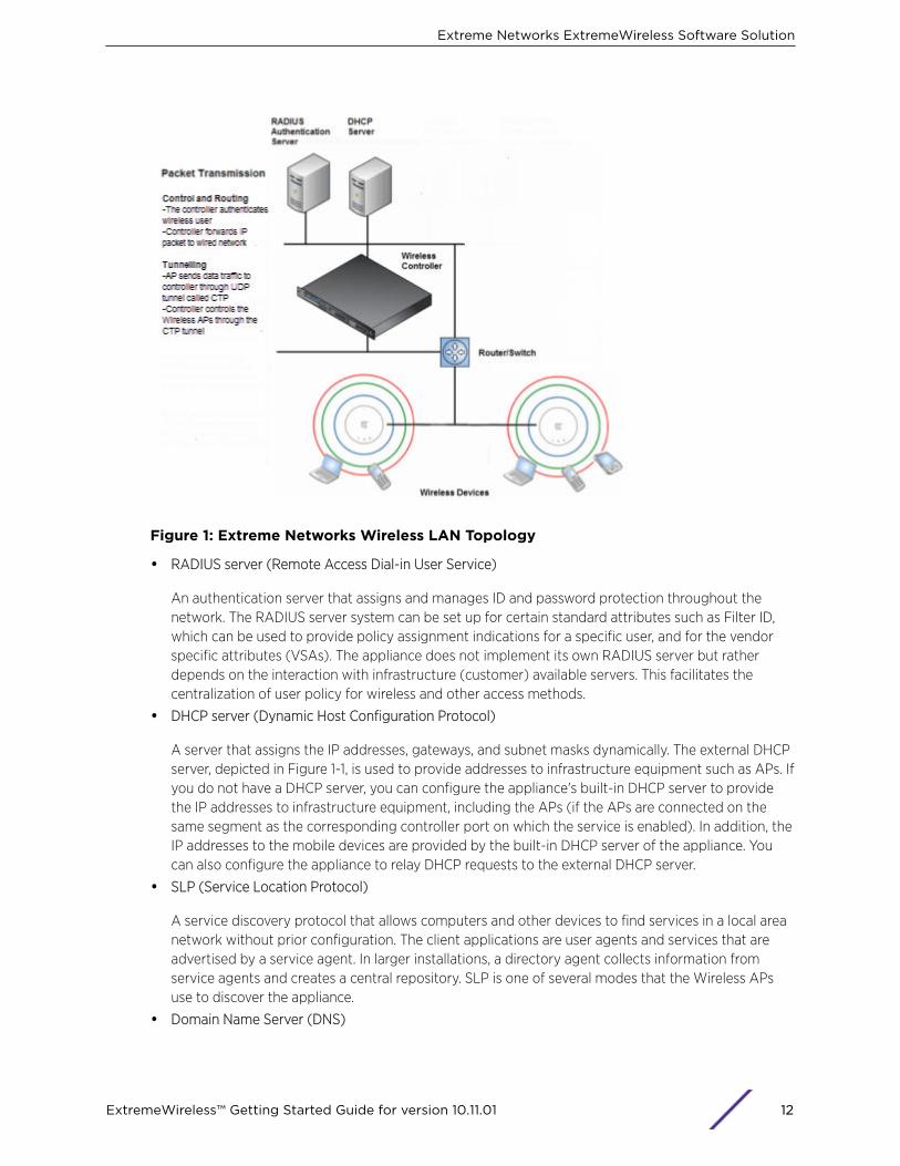
Figure 1: Extreme Networks Wireless LAN Topology
• RADIUS server (Remote Access Dial-in User Service)
An authentication server that assigns and manages ID and password protection throughout thenetwork. The RADIUS server system can be set up for certain standard attributes such as Filter ID,which can be used to provide policy assignment indications for a specific user, and for the vendorspecific attributes (VSAs). The appliance does not implement its own RADIUS server but ratherdepends on the interaction with infrastructure (customer) available servers. This facilitates thecentralization of user policy for wireless and other access methods.
• DHCP server (Dynamic Host Configuration Protocol)
A server that assigns the IP addresses, gateways, and subnet masks dynamically. The external DHCPserver, depicted in Figure 1-1, is used to provide addresses to infrastructure equipment such as APs. Ifyou do not have a DHCP server, you can configure the appliance's built-in DHCP server to providethe IP addresses to infrastructure equipment, including the APs (if the APs are connected on thesame segment as the corresponding controller port on which the service is enabled). In addition, theIP addresses to the mobile devices are provided by the built-in DHCP server of the appliance. Youcan also configure the appliance to relay DHCP requests to the external DHCP server.
• SLP (Service Location Protocol)
A service discovery protocol that allows computers and other devices to find services in a local areanetwork without prior configuration. The client applications are user agents and services that areadvertised by a service agent. In larger installations, a directory agent collects information fromservice agents and creates a central repository. SLP is one of several modes that the Wireless APsuse to discover the appliance.
• Domain Name Server (DNS)
Extreme Networks ExtremeWireless Software Solution
ExtremeWireless™ Getting Started Guide for version 10.11.01 12
A server that translates the domain names into IP addresses. The DNS is used as an alternativemechanism for the automatic discovery process. In addition to an end-user’s usage of DNS to obtainIP references to common internet resources (web-sites), it may also be used as an alternativemethod for AP-Controller discovery. The ExtremeWireless Appliance, its software, and the APs relyon the DNS for Layer 3 deployments. In addition, appliances use DNS to discover their controller. Theappliance can be registered in DNS as controller.<domain> to provide DNS-assisted discovery byAPs
Discovery Mechanisms in the ExtremeWireless Software SolutionThe Extreme Networks ExtremeWireless Software solution provides auto-discovery capabilitiesbetween Wireless APs and ExtremeWireless Appliance Mobility manager and mobility agents. For moreinformation, see the ExtremeWireless User Guide.
Discovery Mechanism Between a Wireless AP and ExtremeWirelessApplianceThe Wireless APs discover the ExtremeWireless Appliance by one of the following modes:
• SLP (Multicast and Unicast) – For more information, see SLP’s description in WLAN SolutionTopology and Network Elements on page 11.
• DNS – For more information, see Domain Name Server’s description in WLAN Solution Topologyand Network Elements on page 11
• Static IP address configuration – ExtremeWireless Appliance’s IP address is defined in the WirelessAP configuration. For more information, see the “Setting up static routes” section of the ExtremeWireless User Guide.
Discovery Mechanism Between Mobility Manager and Mobility AgentsThe mobility agents discover the mobility manager by one of the following modes:
• SLP-DA with DHCP Option 78 – The mobility agent on each ExtremeWireless Appliance discoversthe address of the mobility manager. SLP-DA is a normal network function. If your network alreadydeploys such a device, the controllers will promptly register their services with it (assuming that thecontrollers can identify the device via DHCP Option78 query on its locally attached segments). Ifyour deployment does not have an existing SLP-DA, each controller has that function enabled bydefault (and will correspondingly register with itself). In order for other controllers or APs to find thepreferred SLP-DA for the network, simply provision DHCP Option 78 on each of the requirednetworks to refer to the IP address of the selected controller.
• Direct IP address option – Defined while configuring the mobility agent. By explicitly defining themanager’s IP address while configuring the agents, this enables the manager and agents to findeach other directly without using the SLP discovery mechanism.
DHCP and the Extreme Networks ExtremeWireless SoftwareSolution
The Extreme Networks ExtremeWireless supports the following DHCP configurations per topology:
• Controller is the DHCP server and available for routed topologies. For more information, see “DHCPService Configuration” on page 3-1.
Extreme Networks ExtremeWireless Software Solution
ExtremeWireless™ Getting Started Guide for version 10.11.01 13

• Controller is a DHCP relay agent and available for routed topologies.
• Controller is neither a DHCP server or relay agent and available for Bridged@AP topologies. DHCPfor traffic bridged locally at the Wireless AP is performed by a local DHCP server on the network anddoes not go through a controller at all.
For more information, see the ExtremeWireless User Guide
NoteAll three DHCP configurations are available for Bridged@Controller topologies. ForBridged@Controller topologies, the controller may be configured as the DHCP server for thecorresponding VLAN. In this configuration, the controller bridges all the received traffic from aconnected mobile user to the corresponding VLAN. The VLAN IP assignment must alreadyhave been configured for DHCP service. The wireless user joins that VLAN as a normal wireduser. The address for the user is provided by the corresponding server. The controller learnsthe assigned IP address from a user based on IP inspection.
ExtremeWireless Appliance Physical DescriptionExtremeWireless Appliances are described in detail in the ExtremeWireless Maintenance Guide and inthe Quick Reference Guide for each controller.
Collecting Information for the InstallationBefore installing and configuring your wireless network, consider the following and write down keyinformation that you will need for the process:
• Will the controller be managed remotely via a management, data, or wireless interface? By default,the controller cannot be managed over its data plane or wireless interface. These capabilities mustbe enabled explicitly using the controller's user interface.
• If the controller will be managed over the management port, will IPv4 or IPv6 be used?
• For availability services determine the following:
• WLAN services. Which wireless LAN services will be offered by the controller?
• Privacy settings. Do the WLAN Services require WEP, WPA-PSK, or WPA2 privacy settings?
• Authorization. Will MAC or MAC-based authorization be required prior to gaining access to thenetwork?
• Authentication. Determine the mechanism that is required for users to access each WLANService: None, Captive Portal (internal, external, Guest Portal), AAA/RADIUS/Certificate?RADIUS requires connectivity to an infrastructure RADIUS server.
• The controller's location on the network.
• The segments that the controllers need to connect to.
• The routed or bridged segments that will deliver user traffic.
• The VLANs that the controllers need to connect to.
• The switch ports that provide the VLANs that controllers need to connect to?
• How wireless services map or make use of the available network segments.
• The restrictions that the users will be subject to when accessing the network?
• Controller deployment.
Extreme Networks ExtremeWireless Software Solution
ExtremeWireless™ Getting Started Guide for version 10.11.01 14
• Is more than a single controller going to be deployed? If multiple controllers are deployed, are thecontrollers deployed in availability pairs?
• Are controllers going to be deployed as part of a mobility domain? A mobility domain is acollection of controllers that collaborate to allow stations to roam seamlessly between the APs ofdifferent member controllers.
• Time synchronization. If controllers will be time synchronized, to what source will they besynchronized?
• Controller logs. Will controller logs be remotely aggregated using syslog? If syslog is used,determine the syslog server.
• AP deployment. Will APs be deployed on the same segment or several segments away from thecontroller’s network point?
• AP discovery. Which discovery mechanism will be used to register an AP to the controller: SLP, DNS,multicast, or static listing?
• Controller interfaces. Which controller interfaces will be defined to allow AP registration?
Use the following table to document all the pertinent information about the ExtremeWireless Appliancebefore starting the installation process.
Some of the information listed in the table may not be relevant to your network configuration. Onlyrecord the information that is pertinent to your network configuration.
Extreme Networks ExtremeWireless Software Solution
ExtremeWireless™ Getting Started Guide for version 10.11.01 15
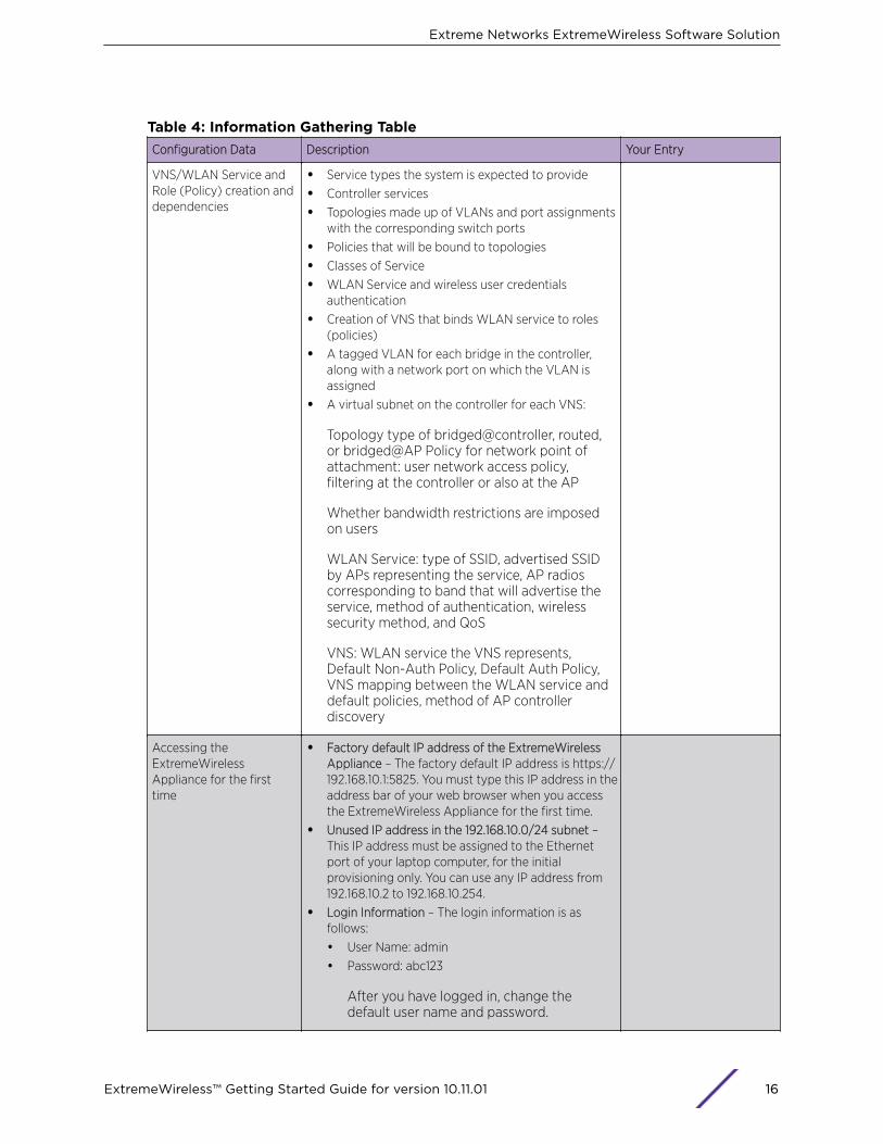
Table 4: Information Gathering TableConfiguration Data Description Your Entry
VNS/WLAN Service andRole (Policy) creation anddependencies
• Service types the system is expected to provide
• Controller services
• Topologies made up of VLANs and port assignmentswith the corresponding switch ports
• Policies that will be bound to topologies
• Classes of Service
• WLAN Service and wireless user credentialsauthentication
• Creation of VNS that binds WLAN service to roles(policies)
• A tagged VLAN for each bridge in the controller,along with a network port on which the VLAN isassigned
• A virtual subnet on the controller for each VNS:
Topology type of bridged@controller, routed,or bridged@AP Policy for network point ofattachment: user network access policy,filtering at the controller or also at the AP
Whether bandwidth restrictions are imposedon users
WLAN Service: type of SSID, advertised SSIDby APs representing the service, AP radioscorresponding to band that will advertise theservice, method of authentication, wirelesssecurity method, and QoS
VNS: WLAN service the VNS represents,Default Non-Auth Policy, Default Auth Policy,VNS mapping between the WLAN service anddefault policies, method of AP controllerdiscovery
Accessing theExtremeWirelessAppliance for the firsttime
• Factory default IP address of the ExtremeWirelessAppliance – The factory default IP address is https://192.168.10.1:5825. You must type this IP address in theaddress bar of your web browser when you accessthe ExtremeWireless Appliance for the first time.
• Unused IP address in the 192.168.10.0/24 subnet –This IP address must be assigned to the Ethernetport of your laptop computer, for the initialprovisioning only. You can use any IP address from192.168.10.2 to 192.168.10.254.
• Login Information – The login information is asfollows:
• User Name: admin
• Password: abc123
After you have logged in, change thedefault user name and password.
Extreme Networks ExtremeWireless Software Solution
ExtremeWireless™ Getting Started Guide for version 10.11.01 16

Table 4: Information Gathering Table (continued)Configuration Data Description Your Entry
System Settings • Hostname – Specifies the name of theExtremeWireless Appliance.
• Domain – Specifies the IP domain name of theenterprise network.
• Primary DNS – The primary DNS server used by thenetwork.
• Secondary DNS – The secondary DNS server used bythe network.
Hardware information MAC Address – MAC address of the ExtremeWirelessAppliance’s management port.
License Key A license key is provided by redeeming an entitlementvoucher on the Extreme Networks website by selectingthe Extreme Networks Activation Key link at page: www.extremenetworks.com/support/. Enter the licensekey for system activation, capacity upgrades, or featureenablement. �
Data Ports PhysicalTopology
• IP address – IP address of the physical Ethernet port.
• Subnet mask – Subnet mask for the IP address,which separates the network portion from the hostportion of the address (typically 255.255.255.0).
• MTU – The maximum transmission unit or maximumpacket size for this port. The default setting is 1500.If you change this setting, and are using OSPF, youmust make sure that the MTU of each port in theOSPF link matches.
• Function – The port’s function.
• Third-party AP Port – A port to which the third-partyAP is connected.
• Router Port – A port that connects to an upstream,next-hop router in the network.
• VLAN ID – The ID of the VLAN to which the AP isconnected.
Static Routing Static IP address – The static IP address that is assignedto the ExtremeWireless Appliance when it is configuredfor static routing.Configurable physical properties:
• Allow Management – Determines whether or not thisparticular interface will allow managementoperations (SNMP, HTTPS, SSH).
• AP Registration – Determines whether this interfaceis advertised as allowing AP registration.
• DHCP Server – Determines whether the controllershould operate as DHCP server for thecorresponding segment.
Extreme Networks ExtremeWireless Software Solution
ExtremeWireless™ Getting Started Guide for version 10.11.01 17

Table 4: Information Gathering Table (continued)Configuration Data Description Your Entry
OSPF Routing Routed VNS – if you are planning to deploy a routedVNS, you may need to enable OSPF on the controller.The OSPF option applies only to routed VNS.
• Router ID – The router ID is its own IP address.
• Area ID of OSPF – ID of OSPF’s area. 0.0.0.0. is themain area in OSPF.
• OSPF Authentication Password – If you selectAuthentication type as Password, you will need toprovide a password.
Extreme Networks ExtremeWireless Software Solution
ExtremeWireless™ Getting Started Guide for version 10.11.01 18

Table 4: Information Gathering Table (continued)Configuration Data Description Your Entry
DHCP service not hostedby controller
Bridge traffic locally at AP – IP assignment is notapplicable; all traffic for users in that VNS will be directlybridged by the AP at the local network point ofattachment; disabled by default.Local server – The ExtremeWireless Appliance's localDHCP server is used for managing IP address allocation:
• Domain Name – The external enterprise domainname server to be used
• Lease default – The default time limit which dictateshow long a wireless device can keep the DHCPserver assigned IP address
• DNS servers – The IP Address of the Domain Nameservers to be used
• WINS – The IP address if the DHCP server usesWindows Internet Naming Service (WINS)
• Enable DLS DHCP Option – An application thatprovides configuration management and softwaredeployment and licensing for optiPoint WL2 phones,if you expect optiPoint WL2 wireless phone traffic onthe VNS.
• Gateway – The ExtremeWireless Appliance’s own IPaddress in the topology, which is the default gatewayfor the topology
• Address Range – The range from which the IPaddress is distributed across the network.
Address range from – The start IP address ofthe range.
Address range to – The end IP address of therange.
DHCP Address exclusion – IP addresses to beexcluded from this range
• Broadcast Address – Automatically populatesautomatically based on the Gateway IP address andsubnet mask of the VNS
Use Relay – The ExtremeWireless Appliance forwardsDHCP requests to an external DHCP server on theenterprise network:
• DHCP servers – IP address of the DHCP server towhich DHCP discover and request messages areforwarded for clients on this VNS
Extreme Networks ExtremeWireless Software Solution
ExtremeWireless™ Getting Started Guide for version 10.11.01 19

Table 4: Information Gathering Table (continued)Configuration Data Description Your Entry
Gateway for installingDHCP service
Gateway – Determine the gateway device for the DHCPservice.
• For a physical topology or bridged@AC, thespecified gateway must be a connecting device onthe same segment.
• For a routed topology, the segment is owned by thecontroller. The controller's interface on the segmentis defined as the default gateway (option3) for thesegment.
Domain name for deviceson this network segment
Domain name – Your organization’s domain name.
RADIUS Server’s IPaddress
IP address – The IP address of the RADIUS server.
SLP DA’s IP address Hexadecimal values of SLP DA’s IP address – TheWireless APs use the SLP DA to discover theExtremeWireless Appliance.The mobility agents use the SLP DA to discover themobility manager.SLP-DA is configured in hexadecimal on the targetDHCP server (this element is not provisioned on thecontroller). The value is configured in relation to option78 on the segment definitions of the DHCP server thatprovides the IP addresses of the APs or that thecontroller can query to determine the selected SLP-DAservice in the network. This provisioning is done persuch segment.
Internet Protocolconfiguration for DNSservice server
• Static IP address – The DNS server’s static IPaddress.
• Subnet Mask – Subnet mask of the DNS server’sstatic IP address.
• Gateway – The DNS server’s gateway.
• ISP’s IP address – Your ISP’s (Internet ServiceProvider) IP address.
• IP address – ExtremeWireless Appliance’s IP address.
Port information forinstalling IAS on the server
• Authentication Port – ExtremeWireless Appliance’sport number used to access the IAS service.
• Accounting Port – Type the ExtremeWirelessAppliance’s port number that is used to access theaccounting service.
The values must match what you define in the Acc &Acct tab.
Extreme Networks ExtremeWireless Software Solution
ExtremeWireless™ Getting Started Guide for version 10.11.01 20

Table 4: Information Gathering Table (continued)Configuration Data Description Your Entry
Wireless AP properties • ExtremeWireless Appliance’s Port # –ExtremeWireless Appliance’s Ethernet port to whichthe Wireless AP is connected.
• Country – The country where the Wireless APoperates.
• Serial # – A unique identifier that is assigned duringthe manufacturing process of the Wireless APs.When an AP discovers and registers with a controller,its name defaults to its serial number, thereforetracking the serial number for an AP helps identifythe specific device, so as to ensure properconfiguration of location dependent settings.
• Hardware version – The current version of theWireless AP hardware.
• Application version – The current version of theWireless AP software.
• VLAN ID – The ID of the VLAN on which the WirelessAP operates.
Next Hop Routing forRouted VNS
An optional configuration element that allows thecustomer to define an explicit next hop router via whichall the segment's traffic should be forwarded. If leftunspecified, the traffic is forwarded in accordance to thesystem's routing table.
• Next hop IP address – The next-hop IP identifies thetarget device to which all VNS (user traffic) isforwarded. Next-hop definition supersedes any otherpossible definition in the routing table.
• OSPF routing cost – The OSPF cost value provides arelative cost indication to allow upstream routers tocalculate whether or not to use the ExtremeWirelessAppliance as a better fit, or lowest cost path to reachthe devices in a particular network. The higher thecost, the less likely that the ExtremeWirelessAppliance is chosen as a route for traffic, unless thatExtremeWireless Appliance is the only possible routefor that traffic.
Extreme Networks ExtremeWireless Software Solution
ExtremeWireless™ Getting Started Guide for version 10.11.01 21
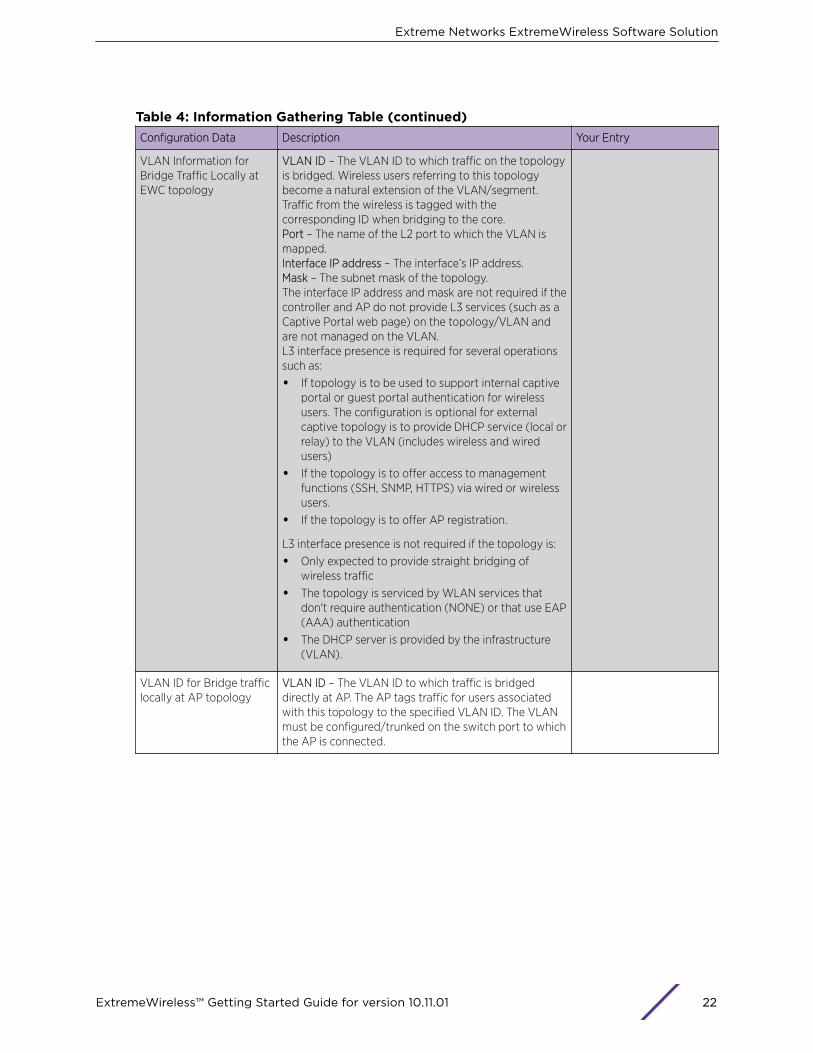
Table 4: Information Gathering Table (continued)Configuration Data Description Your Entry
VLAN Information forBridge Traffic Locally atEWC topology
VLAN ID – The VLAN ID to which traffic on the topologyis bridged. Wireless users referring to this topologybecome a natural extension of the VLAN/segment.Traffic from the wireless is tagged with thecorresponding ID when bridging to the core.Port – The name of the L2 port to which the VLAN ismapped.Interface IP address – The interface’s IP address.Mask – The subnet mask of the topology.The interface IP address and mask are not required if thecontroller and AP do not provide L3 services (such as aCaptive Portal web page) on the topology/VLAN andare not managed on the VLAN.L3 interface presence is required for several operationssuch as:
• If topology is to be used to support internal captiveportal or guest portal authentication for wirelessusers. The configuration is optional for externalcaptive topology is to provide DHCP service (local orrelay) to the VLAN (includes wireless and wiredusers)
• If the topology is to offer access to managementfunctions (SSH, SNMP, HTTPS) via wired or wirelessusers.
• If the topology is to offer AP registration.
L3 interface presence is not required if the topology is:
• Only expected to provide straight bridging ofwireless traffic
• The topology is serviced by WLAN services thatdon't require authentication (NONE) or that use EAP(AAA) authentication
• The DHCP server is provided by the infrastructure(VLAN).
VLAN ID for Bridge trafficlocally at AP topology
VLAN ID – The VLAN ID to which traffic is bridgeddirectly at AP. The AP tags traffic for users associatedwith this topology to the specified VLAN ID. The VLANmust be configured/trunked on the switch port to whichthe AP is connected.
Extreme Networks ExtremeWireless Software Solution
ExtremeWireless™ Getting Started Guide for version 10.11.01 22
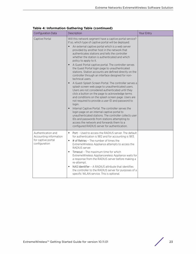
Table 4: Information Gathering Table (continued)Configuration Data Description Your Entry
Captive Portal Will this network segment have a captive portal service?If so, which type of captive portal will be deployed:
• An external captive portal which is a web serverprovided by another host in the network thatauthenticates stations and tells the controllerwhether the station is authenticated and whichpolicy to apply to it.
• A Guest Portal captive portal. The controller servesthe Guest Portal login page to unauthenticatedstations. Station accounts are defined directly on thecontroller through an interface designed for non-technical users.
• A Guest-Splash Screen Portal. The controller serves asplash screen web page to unauthenticated users.Users are not considered authenticated until theyclick a button on the page to acknowledge termsand conditions on the splash screen page. Users arenot required to provide a user ID and password tologin.
• Internal Captive Portal. The controller serves thelogin page on an internal captive portal tounauthenticated stations. The controller collects userIDs and passwords from stations attempting toaccess the network and forwards them to aconfigured RADIUS server for authentication.
Authentication andAccounting informationfor captive portalconfiguration
• Port – Used to access the RADIUS server. The defaultfor authentication is 1812 and for accounting is 1813.
• # of Retries – The number of times theExtremeWireless Appliance attempts to access theRADIUS server.
• Timeout – The maximum time for whichExtremeWireless Appliancereless Appliance waits fora response from the RADIUS server before making are-attempt.
• NAS Identifier – A RADIUS attribute that identifiesthe controller to the RADIUS server for purposes of aspecific WLAN service. This is optional.
Extreme Networks ExtremeWireless Software Solution
ExtremeWireless™ Getting Started Guide for version 10.11.01 23

Table 4: Information Gathering Table (continued)Configuration Data Description Your Entry
Internal Captive Portal,Guest Portal, and Guestsplash screen portalsettings information
• Login Page layout – The controller provides a defaultlogin page for each internal captive portal, guestportal and guest splash screen portal it serves. Thecontroller contains a web page layout editor thatallows the administrator to fully customize the loginpage with custom layouts, graphics and styles.
• Replace Gateway IP with FQDN – By default thecontroller explicitly encodes the IP address of thecorresponding topology (From Non-auth Policydefined by the WLAN service). However, in somecases it is preferable to provide the user with a FullyQualified Domain Name (FQDN). Ensure that theDNS server is configured to map the correspondingname to the topology's IP address.
• Default Redirection URL – By default, once theauthentication completes, the user is redirected backto the initial web site that was intercepted forredirection to authentication. The customer canprovide an explicit override URL to which the user isredirected upon successful authentication.
External Captive Portal(ECP) Type
Select the type of captive portal configuration to provideauthentication services for the WLAN Service:
• No captive portal
• Internal captive portal – Controller provides the webserver that operates as the authentication portal. Thecontroller is also responsible for the credential'sverification with a specified RADIUS server.
• External captive portal – You provide the web serverthat hosts the authentication website. This optionprovides the most flexible approach in terms ofcustomization of the authentication service. Webserver interfaces provide alternate methods of userauthentication, such as payment systems. Or,provide the web service but rely on the controller toperform the credential authentication via RADIUS.
• Internal Guest Portal Splash Screen
• Internal Guest Portal
Shared Secret Passwordfor external captive portalconfiguration
ECP privacy – Whether to require traffic sent betweenthe controller and the external captive portal host to beencrypted and if so with MD5 or AES.Password – When using ECP, define a Shared Secret(password) that can be used to perform MD5 encryptionof sensitive information on the exchange between theauthentication server and the controller (such as duringcredentials exchange for authentication). This passwordencrypts the information exchanged between theExtremeWireless Appliancereless Appliance and theexternal captive portal server.
Extreme Networks ExtremeWireless Software Solution
ExtremeWireless™ Getting Started Guide for version 10.11.01 24
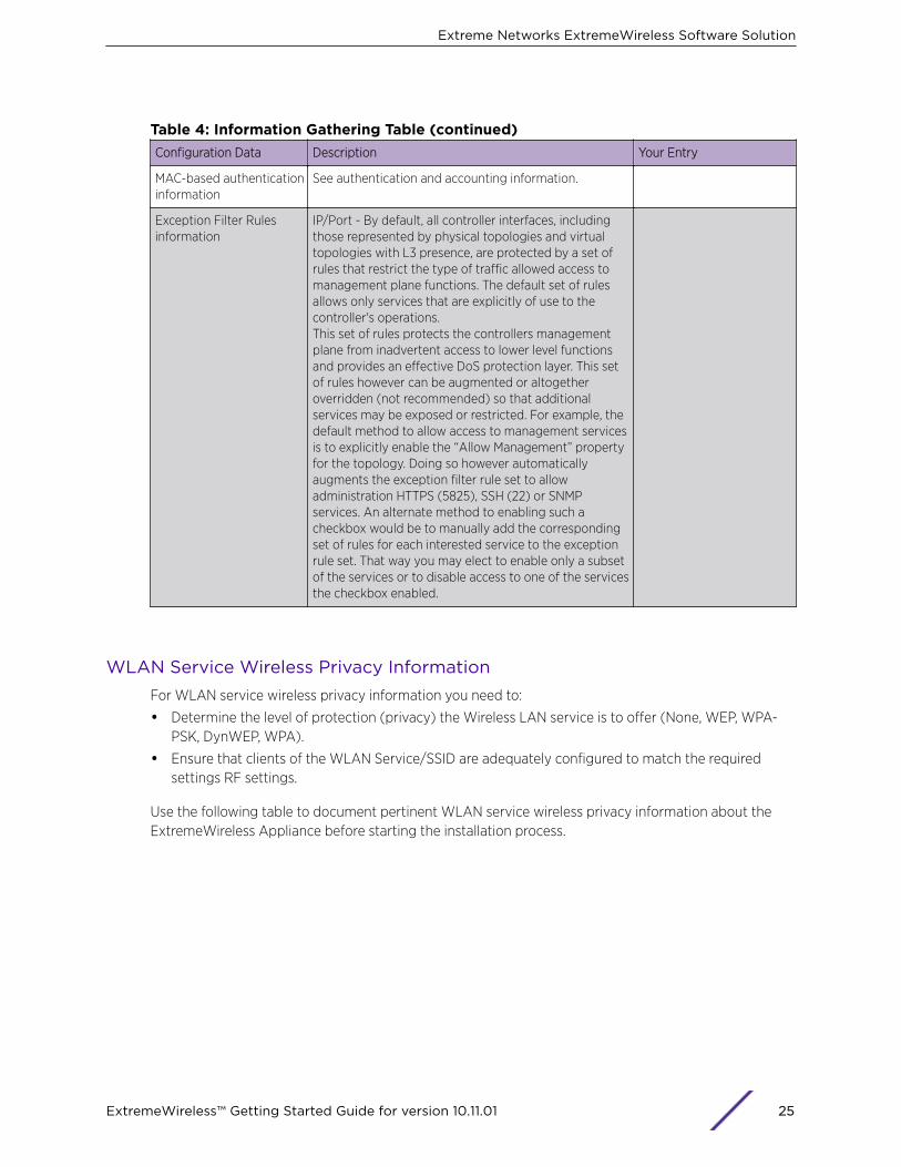
Table 4: Information Gathering Table (continued)Configuration Data Description Your Entry
MAC-based authenticationinformation
See authentication and accounting information.
Exception Filter Rulesinformation
IP/Port - By default, all controller interfaces, includingthose represented by physical topologies and virtualtopologies with L3 presence, are protected by a set ofrules that restrict the type of traffic allowed access tomanagement plane functions. The default set of rulesallows only services that are explicitly of use to thecontroller's operations.This set of rules protects the controllers managementplane from inadvertent access to lower level functionsand provides an effective DoS protection layer. This setof rules however can be augmented or altogetheroverridden (not recommended) so that additionalservices may be exposed or restricted. For example, thedefault method to allow access to management servicesis to explicitly enable the “Allow Management” propertyfor the topology. Doing so however automaticallyaugments the exception filter rule set to allowadministration HTTPS (5825), SSH (22) or SNMPservices. An alternate method to enabling such acheckbox would be to manually add the correspondingset of rules for each interested service to the exceptionrule set. That way you may elect to enable only a subsetof the services or to disable access to one of the servicesthe checkbox enabled.
WLAN Service Wireless Privacy InformationFor WLAN service wireless privacy information you need to:
• Determine the level of protection (privacy) the Wireless LAN service is to offer (None, WEP, WPA-PSK, DynWEP, WPA).
• Ensure that clients of the WLAN Service/SSID are adequately configured to match the requiredsettings RF settings.
Use the following table to document pertinent WLAN service wireless privacy information about theExtremeWireless Appliance before starting the installation process.
Extreme Networks ExtremeWireless Software Solution
ExtremeWireless™ Getting Started Guide for version 10.11.01 25

Table 5: WLAN Service Wireless Privacy InformationConfiguration Data Description Your Entry
Static WEP privacyinformation
Keys for a selected VNS, so that it matches the WEPmechanism used on the rest of the network.
• WEP Key Length – Size of a WEP key.
Select an input method:• Strings – This is the secret WEP key string.• Hex – The WEP key input in the WEP Key box.
The key is generated automatically based onthe input.
WPA-PSK privacyinformation
• WPA v2 or mixed v1 and v2 – The WPA encryption typefurther specifying Auto or TKIP only.
• Broadcast re-key interval – The time interval (inseconds) after which you want the broadcastencryption key to be changed automatically. Thedefault is 3600.
• Pre-shared Key – The shared secret key that is to beused between the wireless device and the Wireless AP.
The shared secret key is used to generate the 256bit key.
Dynamic WEP privacyinformation
Broadcast re-key interval – The time interval (in seconds)after which you want the broadcast encryption key to bechanged automatically. The default is 3600.
Availability Pairs InformationIf deploying controllers in availability pairs, determine the interface over which the availability link isestablished. Manually enable the service on both controllers, or run the Availability Wizard to be guidedthrough the steps necessary to enable paired availability between two controllers. Both controllers areautomatically configured.
Optionally, you can select whether the availability configuration is to be set to use standard or fastfailover operations. If fast-failover is enabled, session-availability is automatically enabled.
You are given the choice to enable automatic configuration synchronization. Once enabled, amodification to service configuration on one controller (such as WLAN services, topologies, andpolicies) is automatically coordinated and synchronized with the peer. You may be requested to provideinformation details pertaining to the representation of the entity on the other controller, such as the IPaddress (layer 3 configuration) of the interface on the other controller.
NoteAutomatic synchronization is strongly recommended when either fast-failover or session-availability is enabled.
Extreme Networks ExtremeWireless Software Solution
ExtremeWireless™ Getting Started Guide for version 10.11.01 26
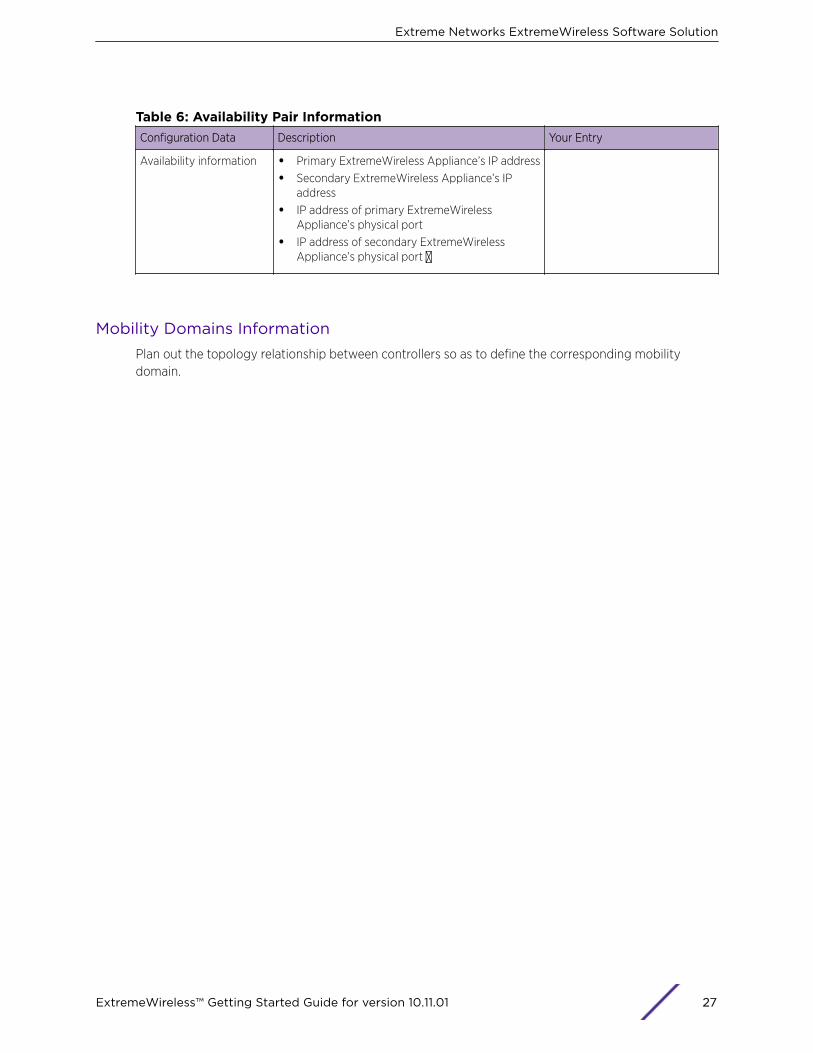
Table 6: Availability Pair InformationConfiguration Data Description Your Entry
Availability information • Primary ExtremeWireless Appliance’s IP address
• Secondary ExtremeWireless Appliance’s IPaddress
• IP address of primary ExtremeWirelessAppliance’s physical port
• IP address of secondary ExtremeWirelessAppliance’s physical port �
Mobility Domains InformationPlan out the topology relationship between controllers so as to define the corresponding mobilitydomain.
Extreme Networks ExtremeWireless Software Solution
ExtremeWireless™ Getting Started Guide for version 10.11.01 27

Table 7: Mobility Settings InformationConfiguration Data Description Your Entry
Mobility managerinformation
If more than one controller is being deployed, it istypically recommended that the inter-controllerdomain service be set up so as to facilitateubiquitous roaming across the various APs on theinfrastructure.Even when the domain is restricted to twocontrollers in an availability pair, inter-controllermobility between the two controllers shouldcorrespondingly be enabled, especially whendeploying services that rely on routed topologies.A mobility domain is characterized by one of thecontrollers defined as the domain's manager and aset of mobility agents. The manager's role is toaggregate, consolidate and distribute the completelist of user-to-controller mapping so that anydomain participant knows which controller mayalready own the session for a roaming user.The manager may be configured to automaticallyaccept any membership domain requests fromagents or may be configured in restricted mode sothat the administrator must explicitly approve theregistration of a new controller into the mobilitydomain.
• Port – The interface of the ExtremeWirelessAppliance that is to be used as the mobilitymanager. Verify that the selected interface isroutable on the network.
• Heartbeat – The time interval (in seconds) atwhich the mobility manager sends a heartbeatmessage to the agent. The default is 5.
Mobility agentinformation
• Port – The interface of the ExtremeWirelessAppliance that is to be used as the mobilityagent. Verify that the selected interface isroutable on the network.
• Heartbeat – The time interval (in seconds) forwhich the mobility agent waits for theconnection establishment response beforetrying again. The default is 60.
• Discovery Method – The method by which themobility agent will discover the mobilitymanager. You have two options:
• SLPD (Service Location Protocol Daemon) –Enables the discovery of the mobilitymanager ExtremeWireless Appliance, usingSLP. The mobility manager's address mustbe configured on the network using SLPwhen selecting this option.
• Static Configuration – Allows the mobilityagent to discover the mobility managerwithout the SLP support. If you select StaticConfiguration, use the IP address of the
Extreme Networks ExtremeWireless Software Solution
ExtremeWireless™ Getting Started Guide for version 10.11.01 28

Table 7: Mobility Settings Information (continued)Configuration Data Description Your Entry
ExtremeWireless Appliance that serves asthe mobility manager.
Extreme Networks ExtremeWireless Software Solution
ExtremeWireless™ Getting Started Guide for version 10.11.01 29

2 Wireless Appliance Configuration
Step 1. Before You Begin ConfigurationStep 2. Prepare the NetworkStep 3. Install the ControllerStep 4. Perform the First Time SetupStep 5. Setting System TimeStep 6. Apply the Activation License KeyStep 7. Configure for AP Controller DiscoveryStep 8. Configure RoutingStep 9. Configure the VNSStep 10. Install, Register, and Assign APs to the VNS
This section provides a high-level overview of the steps involved in the initial configuration of yoursystem:
Step 1. Before You Begin ConfigurationResearch the type of WLAN deployment that is required. For example, SSIDs, security requirements,and filter policies.
Step 2. Prepare the NetworkEnsure that the external servers, such as DHCP and RADIUS servers (if applicable) are available andappropriately configured.
Step 3. Install the ControllerInstall the ExtremeWireless Appliance. For more information, see the appropriate guide from RelatedPublications on page 5.
Step 4. Perform the First Time Setup
NoteVerify that the latest firmware is running on your system by going to the firmware andsoftware link of the Extreme Networks support page at:
https://extranet.extremenetworks.com/downloads
. If the latest firmware is not running on your system, invoke the upgrade procedures asdefined in the ExtremeWireless User Guide.
Perform the first time setup of the ExtremeWireless Appliance on the physical network, which includesconfiguring the IP addresses of the interfaces on the ExtremeWireless Appliance. For more information
ExtremeWireless™ Getting Started Guide for version 10.11.01 30

on the following topics, see the “System Configuration Overview” section in the ExtremeWireless UserGuide.
1 Begin by determining the type of connectivity required between the controller and the switchinfrastructure.
a Determine which physical interfaces (L2 Port) are going to be connected.
b Determine which VLANs are associated with the physical interfaces.
c Determine which Service (Virtual) Topologies are going to be offered by the service and whichphysical interface(s) will carry those VLANs into the switch infrastructure. Ensure that thecorresponding switch ports are provisioned to trunk the same set of VLANs. The L2 PortSummary view provides a listing of which VLAN IDs are configured on which port.
2 The topologies corresponding directly to physical (L2) port connectivity are explicitly identified viathe “Physical” tag as their mode.
NoteIf defining tagged VLANs for topologies, please verify that the same tagged VLANreference is defined on the connecting switch port.
3 To manage the ExtremeWireless Appliance through the interface, select the Mgmt checkbox on thecorresponding Topology profile.
4 Configure the data port interfaces to be on separate VLANs. Ensure also that the tagged versusuntagged state is consistent with the switch port configuration.
5 Configure the ExtremeWireless Appliance for remote access, which includes:
a Setting up an administration station (laptop) on subnet 192.168.10.0/24. By default, theExtremeWireless Appliance's Management interface is configured with the static IP address192.168.10.1.
b If you intend to connect the controller to a dedicated management segment, then the defaultshipping settings of the Admin port (192.168.10.1/24) need to be modified with the correctaddress. A default gateway to which management traffic associated with the Admin port isforwarded may be specified. See “Accessing the ExtremeWireless Appliance for the First Time”on page 2-7.
6 Configure the ExtremeWireless Virtual Gateway V2110, which includes:
a Determining the IP address range of the virtual switch to which the V2110 management port isconnected.
b Using the vSphere Client Console window to assign the controller's management port anavailable IP address on the subnet
c Logging onto the V2110 through its web GUI and use the installation wizard to complete theinitial setup. See Accessing the Wireless Appliance for the First Time on page 37.
Step 5. Setting System TimeYou have the option to manually set the controller's time or use an NTP server to provide a time stampconsistent with a central reference. Controllers that are part of a mobility zone must be configured touse the NTP time stamp. For more information, see “Configure the Network Time Using System Time”section in the Extreme Networks ExtremeWireless Software.
Wireless Appliance Configuration
ExtremeWireless™ Getting Started Guide for version 10.11.01 31
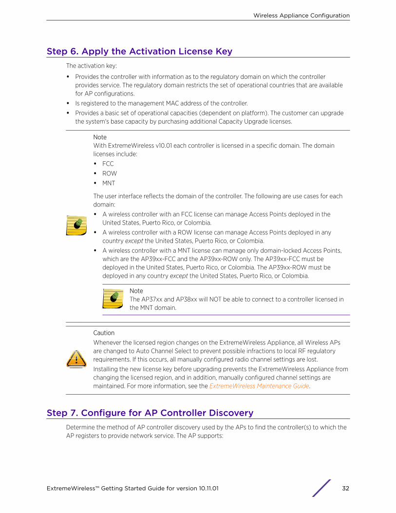
Step 6. Apply the Activation License KeyThe activation key:
• Provides the controller with information as to the regulatory domain on which the controllerprovides service. The regulatory domain restricts the set of operational countries that are availablefor AP configurations.
• Is registered to the management MAC address of the controller.
• Provides a basic set of operational capacities (dependent on platform). The customer can upgradethe system's base capacity by purchasing additional Capacity Upgrade licenses.
NoteWith ExtremeWireless v10.01 each controller is licensed in a specific domain. The domainlicenses include:
• FCC
• ROW
• MNT
The user interface reflects the domain of the controller. The following are use cases for eachdomain:
• A wireless controller with an FCC license can manage Access Points deployed in theUnited States, Puerto Rico, or Colombia.
• A wireless controller with a ROW license can manage Access Points deployed in anycountry except the United States, Puerto Rico, or Colombia.
• A wireless controller with a MNT license can manage only domain-locked Access Points,which are the AP39xx-FCC and the AP39xx-ROW only. The AP39xx-FCC must bedeployed in the United States, Puerto Rico, or Colombia. The AP39xx-ROW must bedeployed in any country except the United States, Puerto Rico, or Colombia.
NoteThe AP37xx and AP38xx will NOT be able to connect to a controller licensed inthe MNT domain.
Caution
Whenever the licensed region changes on the ExtremeWireless Appliance, all Wireless APsare changed to Auto Channel Select to prevent possible infractions to local RF regulatoryrequirements. If this occurs, all manually configured radio channel settings are lost.
Installing the new license key before upgrading prevents the ExtremeWireless Appliance fromchanging the licensed region, and in addition, manually configured channel settings aremaintained. For more information, see the ExtremeWireless Maintenance Guide.
Step 7. Configure for AP Controller DiscoveryDetermine the method of AP controller discovery used by the APs to find the controller(s) to which theAP registers to provide network service. The AP supports:
Wireless Appliance Configuration
ExtremeWireless™ Getting Started Guide for version 10.11.01 32
• SLP-DA Discovery: Configure the segment settings for the DHCP server that provides IP assignmentto the APs to include a reference to the SLP-DA to which WLAN controllers are registered. Thisallows the AP to obtain a list of eligible controllers.
• DNS: Configure the controller.<network domain> entry to resolve to the IP address of a specificcontroller.
• Multicast: Verify that the switching gear and interconnecting VLANs are provisioned so as to allowmulticast traffic, and IGMP snooping allows for the establishment of multicast trees, allowing theAPs to subscribe to SLP-DA server advertisements. The SLP-DA server sends queries to determinethe list of registered controllers.
Step 8. Configure RoutingEven if you are using only bridged topologies on your WLAN, chances are you will need to accessRADIUS servers, NTP servers, Syslog servers, DNS servers, DHCP server for Relay, FTP servers for fileand configuration backup management, and admin stations which may be several hops away from thecontroller. Also, the controller may need to be accessed by stations several hops from the network pointof presence.
Routing configuration for the system is therefore strongly recommended and in most cases necessary.At a minimum the next hop default gateway that the controller interacts with to access these servicesshould be defined.
Step 9. Configure the VNSA VNS is created by binding a particular WLAN Service to one or more policies that are applied towireless stations by default. This mapping can be overridden by authentication or an external interface.The configuration consists of configuring the topologies that represent the method by which user'straffic will be connected to the network.
Policies define the level of access that users are granted, whether users are restricted in the amount ofbandwidth available to the user and the specification on which topology represents the user's point andmethod of network interface. Policies are implicitly assigned by a VNS by way of authentication anddefault states, or may be explicitly assigned by way of responses to user's authentication (RADIUSACCESS-ACCEPT message).
The VNS Creation Wizard on the controller steps you through the service creation and its necessarysubcomponents, resulting in a fully resolved set of elements and an active service.
1 Research the service types the system is expected to provide, such as wireless services, encryptiontypes, infrastructure mapping (VLANs), and connectivity points such as switch ports (switch portVLAN configuration and trunks must match the controller’s configuration. Then configure the traffictopologies your network must support in order to provide wireless user connectivity toinfrastructure resources.
2 You can run the Basic Configuration Wizard to setup controller services such as NTP, Routing, DNS,and RADIUS servers, or you can define necessary infrastructure components such as the RADIUSservers, if CP or AAA services are to be used for user authentication. RADIUS servers are defined viathe “VNS Configuration/Global/Authentication” tab.
3 Define the Topologies: Topologies represent the controller point of network attachment, thereforeVLANS and port assignments must be coordinated with the corresponding switch ports.
Wireless Appliance Configuration
ExtremeWireless™ Getting Started Guide for version 10.11.01 33
4 Define Policies: Policies are typically bound to topologies. Policy application assigns user traffic tothe corresponding network point. Policies define user access rights and reference a user’s ratecontrol profile. New definitions can be created in place.
5 Define the Class of Service (CoS): CoS refers to a set of attributes that define the importance of aframe while it is forwarded through the network relative to other packets, and to the maximumthroughput per time unit that a station or port assigned to the policy is permitted. The CoS definesactions to be taken when rate limits are exceeded.
6 Define the WLAN service:
a Select the set of APs/Radios on which the service is present
b Configure the method of wireless user credential authentication for this service (None, Internal,CP, External CP, Guest Portal, or 802.1x[EAP]
7 Create a VNS that binds the WLAN service to the policies that are used for default assignment uponuser network attachment.
For each Bridge Traffic Locally at EWC topology that is created, a tagged or untagged VLAN needsto be specified. In addition, the network port on which the VLAN is assigned must be configured onthe switch, and the corresponding ExtremeWireless Appliance interface must match the correctVLAN.
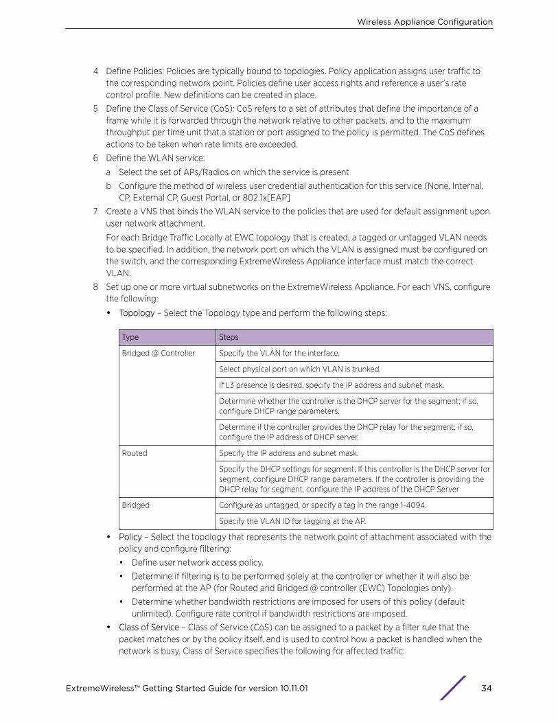
8 Set up one or more virtual subnetworks on the ExtremeWireless Appliance. For each VNS, configurethe following:
• Topology – Select the Topology type and perform the following steps:
Type Steps
Bridged @ Controller Specify the VLAN for the interface.
Select physical port on which VLAN is trunked.
If L3 presence is desired, specify the IP address and subnet mask.
Determine whether the controller is the DHCP server for the segment; if so,configure DHCP range parameters.
Determine if the controller provides the DHCP relay for the segment; if so,configure the IP address of DHCP server.
Routed Specify the IP address and subnet mask.
Specify the DHCP settings for segment; If this controller is the DHCP server forsegment, configure DHCP range parameters. If the controller is providing theDHCP relay for segment, configure the IP address of the DHCP Server
Bridged Configure as untagged, or specify a tag in the range 1-4094.
Specify the VLAN ID for tagging at the AP.
• Policy – Select the topology that represents the network point of attachment associated with thepolicy and configure filtering:
• Define user network access policy.
• Determine if filtering is to be performed solely at the controller or whether it will also beperformed at the AP (for Routed and Bridged @ controller (EWC) Topologies only).
• Determine whether bandwidth restrictions are imposed for users of this policy (defaultunlimited). Configure rate control if bandwidth restrictions are imposed.
• Class of Service – Class of Service (CoS) can be assigned to a packet by a filter rule that thepacket matches or by the policy itself, and is used to control how a packet is handled when thenetwork is busy. Class of Service specifies the following for affected traffic:
Wireless Appliance Configuration
ExtremeWireless™ Getting Started Guide for version 10.11.01 34

• Maximum throughput rates (rate limits)
• Transmit queue assignments, which determines how quickly the packet is forwarded, relativeto other competing traffic.
• Priority remarking behavior, which affects the priority downstream switches and routers giveto the packet.
• The CoS defines actions to be taken when rate limits are exceeded. All incoming packets mayfollow these steps to determine a CoS:
• Each incoming packet is matched against a set of administrator defined rules to find the firstmatching rule that assigns a CoS. If no matching rule that assigns a CoS is found a default CoSis assigned, based on the applied policy.
• Apply new marking to the packet in accordance with the markings defined in the applied CoS.
• Determine whether the packet will cause the station to exceed the rate limit assigned by theCoS. If so, the packet is dropped.
• If the packet is not dropped, select the transmit queue that is used to forward the packet,based on the CoS.
• WLAN Service
• Select the type of service to provide. Select Standard service to provide network access forwireless devices. Define the SSID that is advertised by APs representing this service (The SSIDthat clients see on RF scans).
• Select the AP radios (radios correspond to Band [2.4 GHz, 5 GHz]) that advertise this service.
• Select the method of authentication that users must successfully pass in order to gainnetwork access:
Authentication Method Steps
MBA (MAC address basedauthentication)
Device MAC address must be explicitly allowed to register by RADIUSserver.
Captive Portal
Internal Configure presentation parameters for Captive Portal authenticationpage.
External Configure connectivity parameters for interaction with externalauthentication server.
Guest Portal Define the set of user credentials that will be granted access to theservice.
RADIUS Accounting Define the RADIUS accounting server to which interim usage accountingreports shall be sent.
• Privacy: Select and configure the wireless security method for the service (None, WEP, WPA-PSK, DynWep, WPA/EAP).
• QoS: Configure QoS behavior definitions related to remapping of packet priority.
• VNS
• Select the WLAN service that the VNS represents.
• Configure the Default Non-Auth Policy by selecting the policy to which users are initiallyassigned upon association to the service.
• Configure the Default Auth Policy by selecting the policy to which users are re-assigned uponsuccessful completion of authentication steps (default behavior simply maps to DefaultPolicy, so no specific transition occurs on straight authentication). The policy referenced by
Wireless Appliance Configuration
ExtremeWireless™ Getting Started Guide for version 10.11.01 35

this setting is applied unless the RADIUS server provides a specific indication of a morespecific policy via Login-Lat-Group and/or FilterID attributes.
Provisioning the VNS mapping between the WLAN service and the default policies enables theservice to be advertised (unless WLAN service explicitly provisioned in disabled state).
Step 10. Install, Register, and Assign APs to the VNS1 Deploy Wireless APs to their corresponding network locations.
2 If desired, change the default AP template for common radio and VNS assignment, whereby APsautomatically receive complete configuration. For typical deployments where all APs are to have thesame configuration, this feature expedites deployment, as an AP automatically receives fullconfiguration (including WLAN service assignment) upon initial registration with theExtremeWireless Appliance. If applicable, modify the properties or settings of the Wireless APs.
3 Configure the “Registration mode” that governs how the APs become approved for service with thecontrollers:
Registration Mode Description
Automatic approval The AP discovery process automatically approves the AP so that it becomeseligible to provide service in connection with this controller's configuration.
Restricted Access APs discovering the controller are not automatically approved but rather held in astate “pending” administrator explicit approval. This setting is highly recommendedwhen several controllers may be available for connectivity, such as MobilityDomains or Availability pairs, as it allows the administrator to define whichcontroller is the master point of configuration (Home) for the particular AP.
4 If a default AP configuration template is defined with WLAN service assignment, an approved AP isautomatically assigned to such services.
5 Once the Wireless APs are powered on, they automatically begin the discovery process of theExtremeWireless Appliance.
Wireless Appliance Configuration
ExtremeWireless™ Getting Started Guide for version 10.11.01 36
3 Accessing the Wireless Appliancefor the First TimeWireless Controllers C5210, C5110, C4110, C25, C35 and V2110Management Port Interface
Configuring the Wireless Appliance’s management port is an optional step. If you do not intend toconnect your enterprise network to the controller management port, you can skip the followingprocedure and instead retain the default IP address of the controller’s management port.
Wireless Controllers C5210, C5110, C4110, C25, C35 and V2110The controller platforms have an admin port for dedicated administrative access. They create the IPaddress and Gateway address for the Admin topology on the controller/gateway. The Admin topologyis a default physical topology that references the physical admin port.
Change the controller's management port and Gateway IP addresses using the Command Line Interface(CLI) so that the GUI can be accessed from a browser on the administrator's workstation. After that, thecontroller or V2110 can be accessed via CLI (ssh) or GUI (ssl) for configuration.
ExtremeWireless Appliance GUI via EthernetUse a laptop computer with a web browser. Connect the supplied cross-over Ethernet cable betweenthe laptop and management Ethernet interface of the ExtremeWireless Appliance to performconfiguration via the ExtremeWireless Assistant GUI.
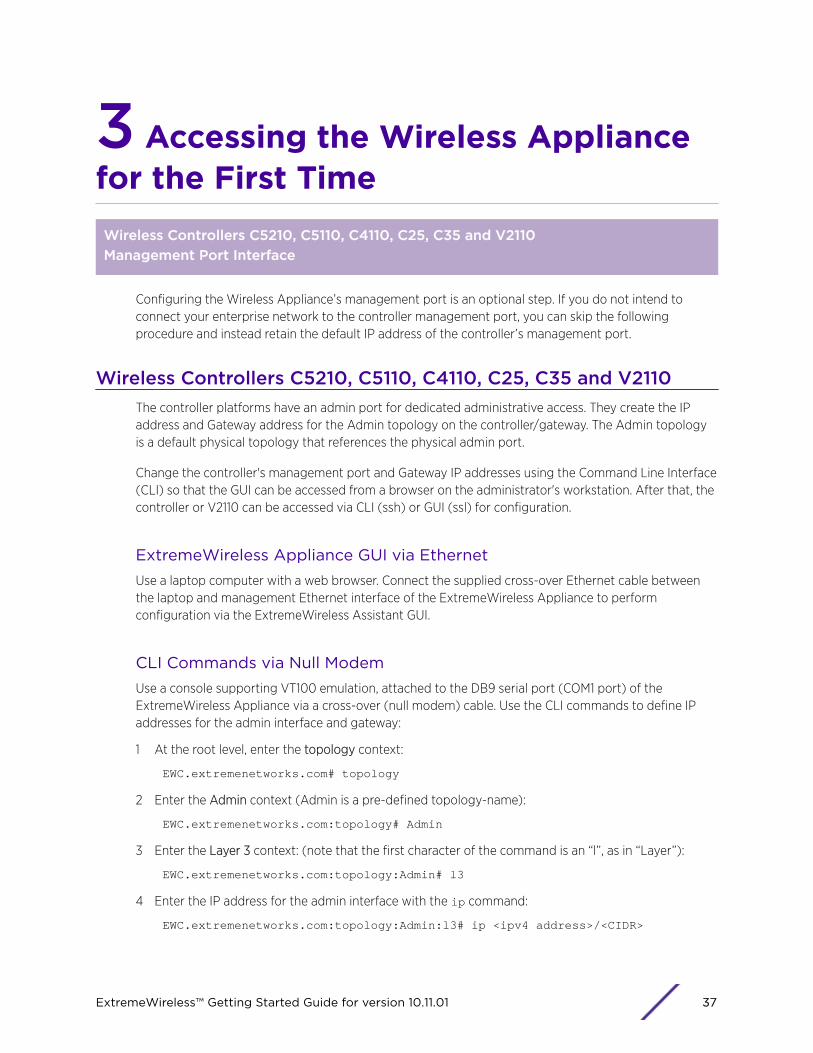
CLI Commands via Null ModemUse a console supporting VT100 emulation, attached to the DB9 serial port (COM1 port) of theExtremeWireless Appliance via a cross-over (null modem) cable. Use the CLI commands to define IPaddresses for the admin interface and gateway:
1 At the root level, enter the topology context:
EWC.extremenetworks.com# topology
2 Enter the Admin context (Admin is a pre-defined topology-name):
EWC.extremenetworks.com:topology# Admin
3 Enter the Layer 3 context: (note that the first character of the command is an “l”, as in “Layer”):
EWC.extremenetworks.com:topology:Admin# l3
4 Enter the IP address for the admin interface with the ip command:
EWC.extremenetworks.com:topology:Admin:l3# ip <ipv4 address>/<CIDR>
ExtremeWireless™ Getting Started Guide for version 10.11.01 37
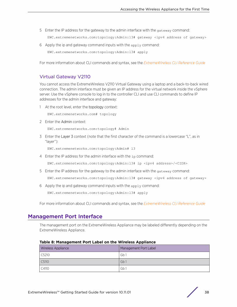
5 Enter the IP address for the gateway to the admin interface with the gateway command:
EWC.extremenetworks.com:topology:Admin:l3# gateway <ipv4 address of gateway>
6 Apply the ip and gateway command inputs with the apply command:
EWC.extremenetworks.com:topology:Admin:l3# apply
For more information about CLI commands and syntax, see the ExtremeWireless CLI Reference Guide
Virtual Gateway V2110You cannot access the ExtremeWireless V2110 Virtual Gateway using a laptop and a back-to-back wiredconnection. The admin interface must be given an IP address for the virtual network inside the vSphereserver. Use the vSphere console to log in to the controller CLI and use CLI commands to define IPaddresses for the admin interface and gateway:
1 At the root level, enter the topology context:
EWC.extremenetworks.com# topology
2 Enter the Admin context:
EWC.extremenetworks.com:topology# Admin
3 Enter the Layer 3 context (note that the first character of the command is a lowercase “L”, as in“layer”):
EWC.extremenetworks.com:topology:Admin# l3
4 Enter the IP address for the admin interface with the ip command:
EWC.extremenetworks.com:topology:Admin:l3# ip <ipv4 address>/<CIDR>
5 Enter the IP address for the gateway to the admin interface with the gateway command:
EWC.extremenetworks.com:topology:Admin:l3# gateway <ipv4 address of gateway>
6 Apply the ip and gateway command inputs with the apply command:
EWC.extremenetworks.com:topology:Admin:l3# apply
For more information about CLI commands and syntax, see the ExtremeWireless CLI Reference Guide
Management Port InterfaceThe management port on the ExtremeWireless Appliance may be labeled differently depending on theExtremeWireless Appliance.
Table 8: Management Port Label on the Wireless ApplianceWireless Appliance Management Port Label
C5210 Gb 1
C5110 Gb 1
C4110 Gb 1
Accessing the Wireless Appliance for the First Time
ExtremeWireless™ Getting Started Guide for version 10.11.01 38

Table 8: Management Port Label on the Wireless Appliance (continued)Wireless Appliance Management Port Label
C25 1 GbE
C35 1 GbE
Accessing the Wireless Appliance with a Web-enabled Laptop1 Statically assign an unused IP address in the 192.168.10.0/24 subnet for the Ethernet port of the
laptop computer.
You can use any IP address from 192.168.10.2 to 192.168.10.254.
2 Connect the ExtremeWireless Appliance’s management port to the web-enabled laptop computerwith a cross-over RJ45 Ethernet cable.
NoteThe IP address of the ExtremeWireless Appliance’s management port is 192.168.10.1.
3 Launch your web browser and type https://192.168.10.1:5825 in the address bar.
The Wireless Assistant login screen displays.
4 Enter the credentials:
User Name: admin
Password: abc123
Accessing the Wireless Appliance for the First Time
ExtremeWireless™ Getting Started Guide for version 10.11.01 39

5 Click Login.
The Wireless Assistant Home screen displays.
Accessing the Wireless Appliance for the First Time
ExtremeWireless™ Getting Started Guide for version 10.11.01 40
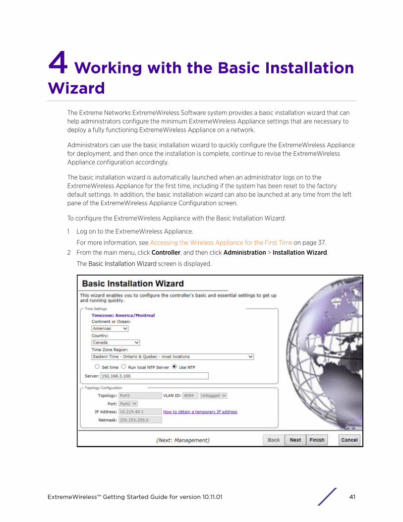
4 Working with the Basic InstallationWizard
The Extreme Networks ExtremeWireless Software system provides a basic installation wizard that canhelp administrators configure the minimum ExtremeWireless Appliance settings that are necessary todeploy a fully functioning ExtremeWireless Appliance on a network.
Administrators can use the basic installation wizard to quickly configure the ExtremeWireless Appliancefor deployment, and then once the installation is complete, continue to revise the ExtremeWirelessAppliance configuration accordingly.
The basic installation wizard is automatically launched when an administrator logs on to theExtremeWireless Appliance for the first time, including if the system has been reset to the factorydefault settings. In addition, the basic installation wizard can also be launched at any time from the leftpane of the ExtremeWireless Appliance Configuration screen.
To configure the ExtremeWireless Appliance with the Basic Installation Wizard:
1 Log on to the ExtremeWireless Appliance.
For more information, see Accessing the Wireless Appliance for the First Time on page 37.
2 From the main menu, click Controller, and then click Administration > Installation Wizard.
The Basic Installation Wizard screen is displayed.
ExtremeWireless™ Getting Started Guide for version 10.11.01 41

3 In the Time Settings section, configure the Wireless Appliance timezone:
• Continent or Ocean – Click the appropriate large-scale geographic grouping for the time zone.
• Country – Click the appropriate country for the time zone. The contents of the drop-down listchange, based on the selection in the Continent or Ocean drop-down list.
• Time Zone Region – Select the appropriate time zone region for the selected country from thedrop-down menu.
4 To configure the Wireless Appliance’s time, do one of the following:
• To manually set the ExtremeWireless Appliance time, click Set time and specify values for theYear, Month, Day, HR, and Min.
To use the ExtremeWireless Appliance as the NTP time server, select Run local NTP Server. Inthe Server field, enter the IP address or Domain Name for the NTP server.
• To use NTP to set the ExtremeWireless Appliance time, select Use NTP, and then type the IPaddress of an NTP time server that is accessible on the enterprise network.
The Network Time Protocol is a protocol for synchronizing the clocks of computer systems overpacket-switched data networks.
NoteThe Server Address field supports both IPv4 and IPv6 addresses.
5 You can configure up to three DNS servers. The Server Address field supports both IPv4 and IPv6addresses. In the Topology Configuration section, the physical interface of the Wireless Appliancedata port, the IP Address and Netmask values for the data port, and the VLAN ID display as read-only values.
For information on how to obtain a temporary IP address from the network, click How to obtain atemporary IP address.
Working with the Basic Installation Wizard
ExtremeWireless™ Getting Started Guide for version 10.11.01 42

6 Click Next.
The Management screen displays.
7 In the AP Password section, enter a password for the AP. Click Unmask to display the passwordcharacters as you type. Access Points are shipped with default passwords. You must create a newSSH Access Password here.
Note
Passwords can include the following characters: A-Z a-z 0-9 ~!@#$%^&*()_+|-=\{}[];<>?,.
Password cannot include the following characters: / ` ' " : or a space.
8 In the Management Port section, confirm the port configuration values that were defined when theWireless Appliance was physically deployed on the network. If applicable, edit these values:
• Static IP Address — Displays the IPv4 address for the ExtremeWireless Appliance's managementport. Revise this as appropriate for the enterprise network.
• Netmask — Displays the appropriate subnet mask for the IP address to separate the networkportion from the host portion of the address.
• Gateway — Displays the default gateway of the network.
• Static IPv6 Address — Displays the IPv6 address for the ExtremeWireless Appliance'smanagement port. Revise this as appropriate for the enterprise network.
• Prefix Length — Length of the IPv6 prefix. Maximum is 64 bits.
• Gateway — Displays the default gateway of the network.
Working with the Basic Installation Wizard
ExtremeWireless™ Getting Started Guide for version 10.11.01 43
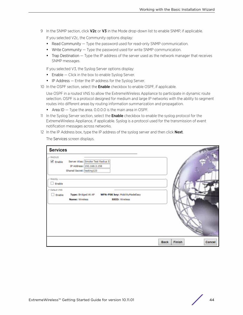
9 In the SNMP section, click V2c or V3 in the Mode drop-down list to enable SNMP, if applicable.
If you selected V2c, the Community options display:
• Read Community — Type the password used for read-only SNMP communication.
• Write Community — Type the password used for write SNMP communication.
• Trap Destination — Type the IP address of the server used as the network manager that receivesSNMP messages.
If you selected V3, the Syslog Server options display:
• Enable — Click in the box to enable Syslog Server.
• IP Address — Enter the IP address for the Syslog Server.
10 In the OSPF section, select the Enable checkbox to enable OSPF, if applicable.
Use OSPF in a routed VNS to allow the ExtremeWireless Appliance to participate in dynamic routeselection. OSPF is a protocol designed for medium and large IP networks with the ability to segmentroutes into different areas by routing information summarization and propagation.
• Area ID — Type the area. 0.0.0.0 is the main area in OSPF.
11 In the Syslog Server section, select the Enable checkbox to enable the syslog protocol for theExtremeWireless Appliance, if applicable. Syslog is a protocol used for the transmission of eventnotification messages across networks.
12 In the IP Address box, type the IP address of the syslog server and then click Next.
The Services screen displays.
Working with the Basic Installation Wizard
ExtremeWireless™ Getting Started Guide for version 10.11.01 44
13 In the RADIUS section, select the Enable checkbox to enable RADIUS login authentication, ifapplicable.
RADIUS login authentication uses a RADIUS server to authenticate user login attempts. RADIUS is aclient/server authentication and authorization access protocol used by a network access server(NAS) to authenticate users attempting to connect to a network device.
• Server Alias — Type a name that you want to assign to the RADIUS server.
• IP Address — Type the RADIUS server’s IP address.
• Shared Secret — Type the password that is used to validate the connection between the WirelessAppliance and the RADIUS server.
14 In the Mobility section, select the Enable checkbox to enable the ExtremeWireless Appliancemobility feature, if applicable. Mobility allows a wireless device user to roam seamlessly betweendifferent Wireless APs on different appliances.
A dialog displays, informing you that NTP is required for the mobility feature and prompting you toconfirm you want to enable mobility.
NoteIf the Wireless Appliance is configured as a mobility agent, it acts as an NTP client anduses the mobility manager as the NTP server. If the Wireless Appliance is configured as amobility manager, the Wireless Appliance’s local NTP is enabled for the mobility domain.
15 Click OK to continue, and then do the following:
• Role — Select the role for the ExtremeWireless Appliance, Manager or Agent. One appliance onthe network is designated as the mobility manager and all appliances are designated as mobilityagents.
• Port — Click the interface on the ExtremeWireless Appliance to be used for communicationbetween mobility manager and mobility agent. Verify that the selected interface is routable onthe network.
• Manager IP — Type the IP address of the mobility manager port if the appliance is configured asthe mobility agent.
16 In the Default VNS section, select the Enable checkbox to enable a default VNS for the appliance.
The default VNS parameters display.
Working with the Basic Installation Wizard
ExtremeWireless™ Getting Started Guide for version 10.11.01 45

17 Click Next.
The Success screen displays.
18 Change the factory default administrator password. Enter the new password and confirm it, andthen click Save.
19 Click OK, and then Close.
The ExtremeWireless Assistant main menu screen displays.
NoteThe appliance reboots after you click Save if the time zone is changed during the Basic InstallWizard. If the IP address of the management port is changed during the configuration withthe Basic Install Wizard, the ExtremeWireless Assistant session is terminated and you willhave to log back in with the new IP address.
Working with the Basic Installation Wizard
ExtremeWireless™ Getting Started Guide for version 10.11.01 46

5 Connecting the Wireless Applianceto the Enterprise Network
1 Disconnect your laptop computer from the Wireless Appliance management port.
2 Connect the Wireless Appliance management port to the enterprise Ethernet LAN. The WirelessAppliance resets automatically.
3 Log on to the Wireless Assistant from any computer on the enterprise network. Type the followingURL in a browser to access the Wireless Assistant: https://<IP Address>:5825
ExtremeWireless™ Getting Started Guide for version 10.11.01 47

6 Configuring the WirelessAppliance for the First Time
Some Wireless Appliance configuration is typically performed as soon as the Wireless Appliance isdeployed.
Although the basic installation wizard has already configured some aspects of the Wireless Appliancedeployment, you can continue to revise the ExtremeWireless Appliance configuration according to yournetwork needs.
For more information on the following topics, see the ExtremeWireless User Guide.
• Changing the administrator passwords
• Configuring the network time
• Applying license keys
• Configuring physical topology
• Configuring Wireless APs
• Configuring the list of RADIUS servers
• Configuring DNS settings/list of DNS servers (if necessary)
• Configuring Syslog server (if necessary to dynamically upload log messages/event occurrences onthe controller)
• If required, configuring SNMP Agent access parameters
• Configuring controller network identification, including hostname and domain
• Configuring VNSs
• Configuring topologies the controller services represent
• Configuring policy parameters for user network access
• Configuring WLAN services and AP membership
• Configuring the set of VNSs mapping WLAN services to policies for default assignment
• Configuring availability
• Configuring mobility
ExtremeWireless™ Getting Started Guide for version 10.11.01 48
7 Configuring DHCP, NPS, and DNSServicesDHCP Service ConfigurationConfiguring the ExtremeWireless Appliance as an NPS ClientNPS Service ConfigurationDNS Service Configuration
This chapter describes how to configure DHCP (Dynamic Host Configuration Protocol) and DNS(Domain Name System) services on a Windows Server 2012 R2 or Linux server for use byExtremeWireless Appliance and APs. In addition, the chapter explains how to configure Network PolicyServer (NPS) service on Windows Server 2012 R2. Use the configuration processes in this chapter as areference when configuring services.
NoteWindows Server 2012 R2 or Linux server may have a different configuration process thanwhat is described here. Refer to your manufacturer’s documentation for the configurationprocess that is specific to your server.
This section includes the following procedures:
• DHCP Service Configuration on page 49
• NPS Service Configuration on page 66
• DNS Service Configuration on page 72
DHCP Service ConfigurationBefore you can configure the DHCP service, you must install it on the server. You can configure DHCP onWindows Server 2012 R2 or on a Red Hat Linux server.
This section includes the following procedures:
• Configuring DHCP on Windows Server 2012 R2 on page 49
• Configuring DHCP on a Red Hat Linux Server on page 63
Configuring DHCP on Windows Server 2012 R2Install DHCP either during the initial installation of Windows Server 2012 R2 or after the initialinstallation is completed.
When you configure DHCP for ExtremeWireless LAN (WLAN) solution, you can include 078 SLP DAOption.
You must enable 078 SLP DA Option for every scope you define. A scope is a collection of IP addressesmeant to be distributed by the DHCP server to the client devices on a subnet. The SLP DA is used by:
ExtremeWireless™ Getting Started Guide for version 10.11.01 49

• The Wireless APs to discover the ExtremeWireless Appliance.
• The mobility agents to discover the mobility manager.
NoteYou may visit http://support.microsoft.com for instructions on how to install DHCP.
Configure DHCP option 43 for ExtremeWireless Appliance discovery when there is a need for a specificAP platform to connect to a specific controller.
For more information, see:
• Creating Option 78 on page 50
• Configuring Option 78 on page 50
• DHCP Option 43 on Windows Server 2012 R2 on page 54
Creating Option 78
To create option 78 as a byte array, perform the following steps:
1 Click Start > Administrative Tool > DHCP2 Right-click the server node, and select Set predefined options.
3 Select Add, and type a name for the option, for example "SLP DA".
4 Set the data type to Byte, and select the Array checkbox.
5 In the Code field, type 78.
6 Type a description for the option, for example, "Extreme Networks SLP Discovery", and then selectOK.
Figure 2: Option Type
Configuring Option 78
To configure DHCP on Windows Server 2012 R2:
1 Click Start > Administrative Tool > DHCP.
2 In the console tree, right-click the DHCP server, IPv4 on which you want to create the new DHCPscope, and then click New Scope.
3 Click Next.
Configuring DHCP, NPS, and DNS Services
ExtremeWireless™ Getting Started Guide for version 10.11.01 50
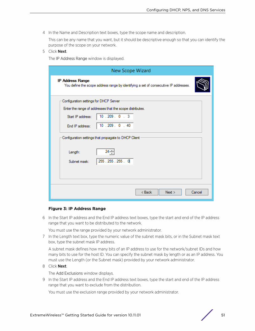
4 In the Name and Description text boxes, type the scope name and description.
This can be any name that you want, but it should be descriptive enough so that you can identify thepurpose of the scope on your network.
5 Click Next.
The IP Address Range window is displayed.
Figure 3: IP Address Range
6 In the Start IP address and the End IP address text boxes, type the start and end of the IP addressrange that you want to be distributed to the network.
You must use the range provided by your network administrator.
7 In the Length text box, type the numeric value of the subnet mask bits, or in the Subnet mask textbox, type the subnet mask IP address.
A subnet mask defines how many bits of an IP address to use for the network/subnet IDs and howmany bits to use for the host ID. You can specify the subnet mask by length or as an IP address. Youmust use the Length (or the Subnet mask) provided by your network administrator.
8 Click Next.
The Add Exclusions window displays.
9 In the Start IP address and the End IP address text boxes, type the start and end of the IP addressrange that you want to exclude from the distribution.
You must use the exclusion range provided by your network administrator.
Configuring DHCP, NPS, and DNS Services
ExtremeWireless™ Getting Started Guide for version 10.11.01 51
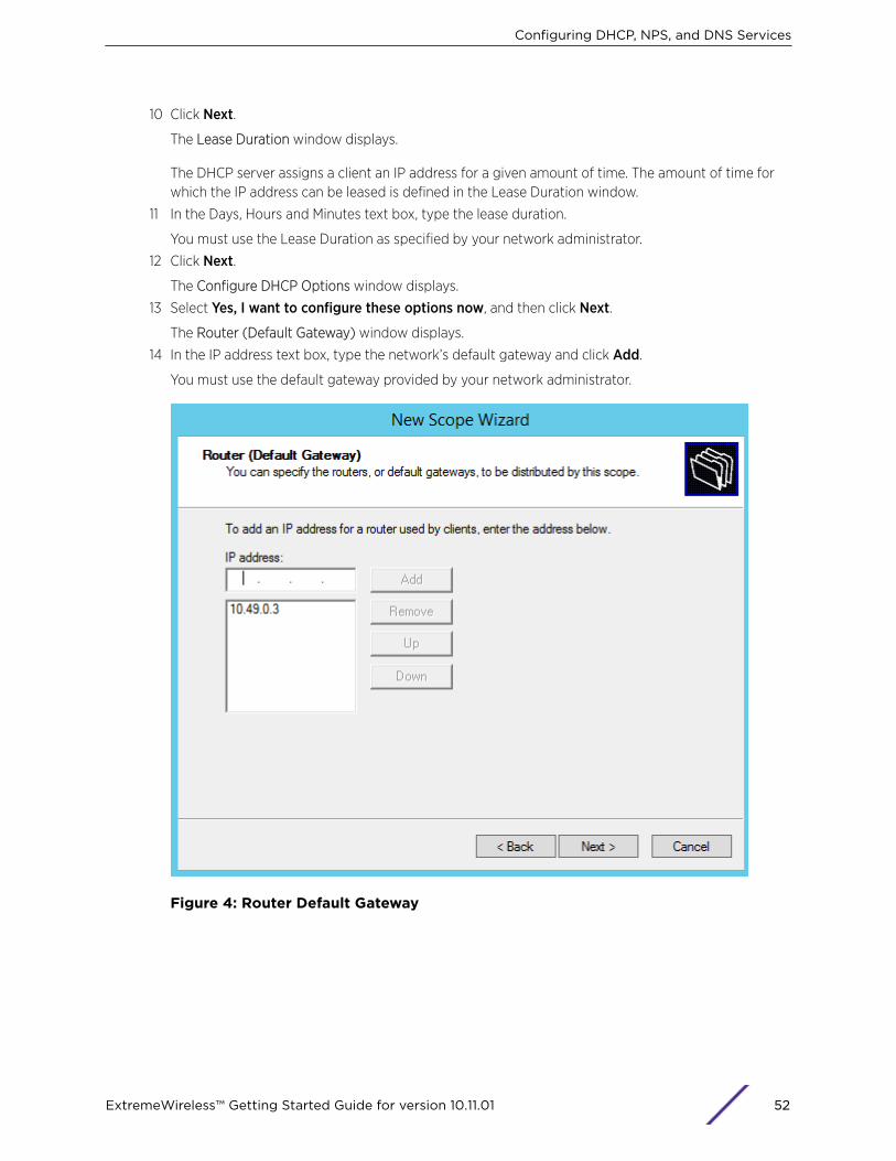
10 Click Next.
The Lease Duration window displays.
The DHCP server assigns a client an IP address for a given amount of time. The amount of time forwhich the IP address can be leased is defined in the Lease Duration window.
11 In the Days, Hours and Minutes text box, type the lease duration.
You must use the Lease Duration as specified by your network administrator.
12 Click Next.
The Configure DHCP Options window displays.
13 Select Yes, I want to configure these options now, and then click Next.
The Router (Default Gateway) window displays.
14 In the IP address text box, type the network’s default gateway and click Add.
You must use the default gateway provided by your network administrator.
Figure 4: Router Default Gateway
Configuring DHCP, NPS, and DNS Services
ExtremeWireless™ Getting Started Guide for version 10.11.01 52
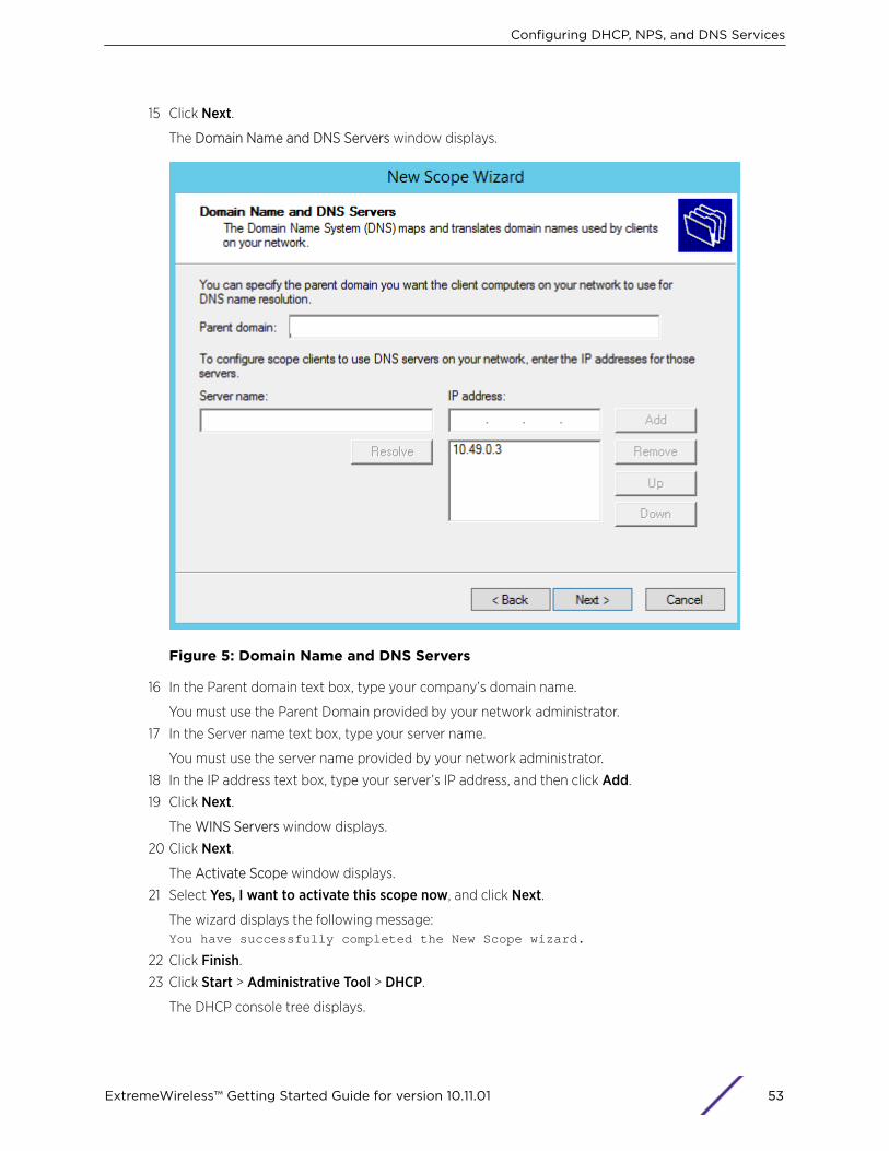
15 Click Next.
The Domain Name and DNS Servers window displays.
Figure 5: Domain Name and DNS Servers
16 In the Parent domain text box, type your company’s domain name.
You must use the Parent Domain provided by your network administrator.
17 In the Server name text box, type your server name.
You must use the server name provided by your network administrator.
18 In the IP address text box, type your server’s IP address, and then click Add.
19 Click Next.
The WINS Servers window displays.
20 Click Next.
The Activate Scope window displays.
21 Select Yes, I want to activate this scope now, and click Next.
The wizard displays the following message:You have successfully completed the New Scope wizard.
22 Click Finish.
23 Click Start > Administrative Tool > DHCP.
The DHCP console tree displays.
Configuring DHCP, NPS, and DNS Services
ExtremeWireless™ Getting Started Guide for version 10.11.01 53

24 Right-click Server Options in the tree and select Configure Options.
Figure 6: Configure Options
The Server Options dialog displays.
25 On the General tab, enable 078 SLP DA.
26 In the lower pane of the screen, type the dotted decimal values of the SLP DA’s IP address.
The Wireless APs use the SLP DA to discover the ExtremeWireless Appliance.
The mobility agents use the SLP DA to discover the mobility manager.
Note
If there is no SLP deployment on the enterprise network, the ExtremeWireless Appliance isconfigured to act as a DA by default. If you put the appliance's IP address(es) in a DHCPserver for Option 78, Wireless APs will interact with the appliance for discovery.
Similarly, the mobility agents also interact with the ExtremeWireless Appliance to discoverthe mobility manager.
DHCP Option 43 on Windows Server 2012 R2
This section describes how to configure the Microsoft DHCP server to use DHCP option 43 forExtremeWireless Appliance discovery. In the discovery process, the DHCP server returns vendor-specificinformation to the client as option 43. You must supply the following information to configure DHCPoption 43:
• Vendor Class Identifier (VCI) — The VCI for an Extreme Networks AP is ExtremeWireless <AP modelname>.
Configuring DHCP, NPS, and DNS Services
ExtremeWireless™ Getting Started Guide for version 10.11.01 54
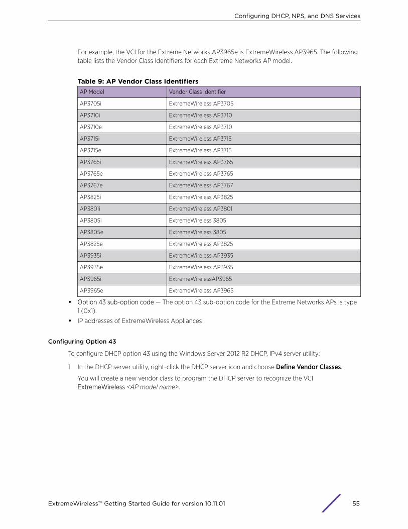
For example, the VCI for the Extreme Networks AP3965e is ExtremeWireless AP3965. The followingtable lists the Vendor Class Identifiers for each Extreme Networks AP model.
Table 9: AP Vendor Class IdentifiersAP Model Vendor Class Identifier
AP3705i ExtremeWireless AP3705
AP3710i ExtremeWireless AP3710
AP3710e ExtremeWireless AP3710
AP3715i ExtremeWireless AP3715
AP3715e ExtremeWireless AP3715
AP3765i ExtremeWireless AP3765
AP3765e ExtremeWireless AP3765
AP3767e ExtremeWireless AP3767
AP3825i ExtremeWireless AP3825
AP3801i ExtremeWireless AP3801
AP3805i ExtremeWireless 3805
AP3805e ExtremeWireless 3805
AP3825e ExtremeWireless AP3825
AP3935i ExtremeWireless AP3935
AP3935e ExtremeWireless AP3935
AP3965i ExtremeWirelessAP3965
AP3965e ExtremeWireless AP3965
• Option 43 sub-option code — The option 43 sub-option code for the Extreme Networks APs is type1 (0x1).
• IP addresses of ExtremeWireless Appliances
Configuring Option 43
To configure DHCP option 43 using the Windows Server 2012 R2 DHCP, IPv4 server utility:
1 In the DHCP server utility, right-click the DHCP server icon and choose Define Vendor Classes.
You will create a new vendor class to program the DHCP server to recognize the VCIExtremeWireless <AP model name>.
Configuring DHCP, NPS, and DNS Services
ExtremeWireless™ Getting Started Guide for version 10.11.01 55
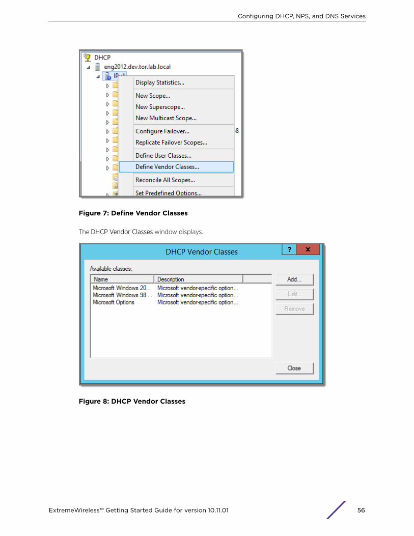
Figure 7: Define Vendor Classes
The DHCP Vendor Classes window displays.
Figure 8: DHCP Vendor Classes
Configuring DHCP, NPS, and DNS Services
ExtremeWireless™ Getting Started Guide for version 10.11.01 56

2 Click Add to create the new class.
The New Class window displays.
Figure 9: New Class
3 In the Display name field, enter a name. In this example, AP3965 is used as the display name.
4 In the Description field, enter a short description of the vendor class: AP3965.
5 Add the Vendor Class Identifier string. Click the ASCII field, and enter the appropriate value (forexample, AP3965).
Configuring DHCP, NPS, and DNS Services
ExtremeWireless™ Getting Started Guide for version 10.11.01 57

6 Click OK.
The new class is created.
Figure 10: DHCP Vendor Classes
7 Click Close.
8 In the DHCP server, IPv4 utility, right-click the server icon and select Set Predefined Options to addan entry for the WLAN controller sub-option for the newly created vendor class.
The sub-option code type and the data format is used to deliver the vendor specific information tothe APs.
Configuring DHCP, NPS, and DNS Services
ExtremeWireless™ Getting Started Guide for version 10.11.01 58
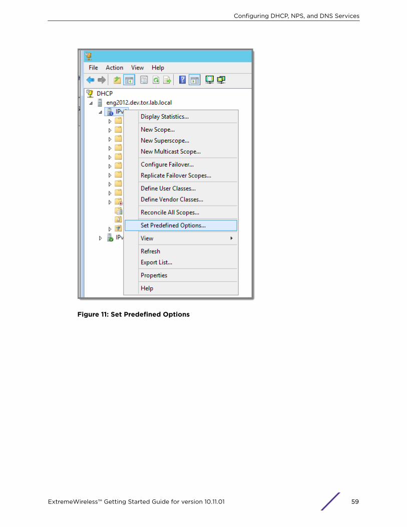
Figure 11: Set Predefined Options
Configuring DHCP, NPS, and DNS Services
ExtremeWireless™ Getting Started Guide for version 10.11.01 59

Figure 12: Predefined Options and Values
Configuring DHCP, NPS, and DNS Services
ExtremeWireless™ Getting Started Guide for version 10.11.01 60
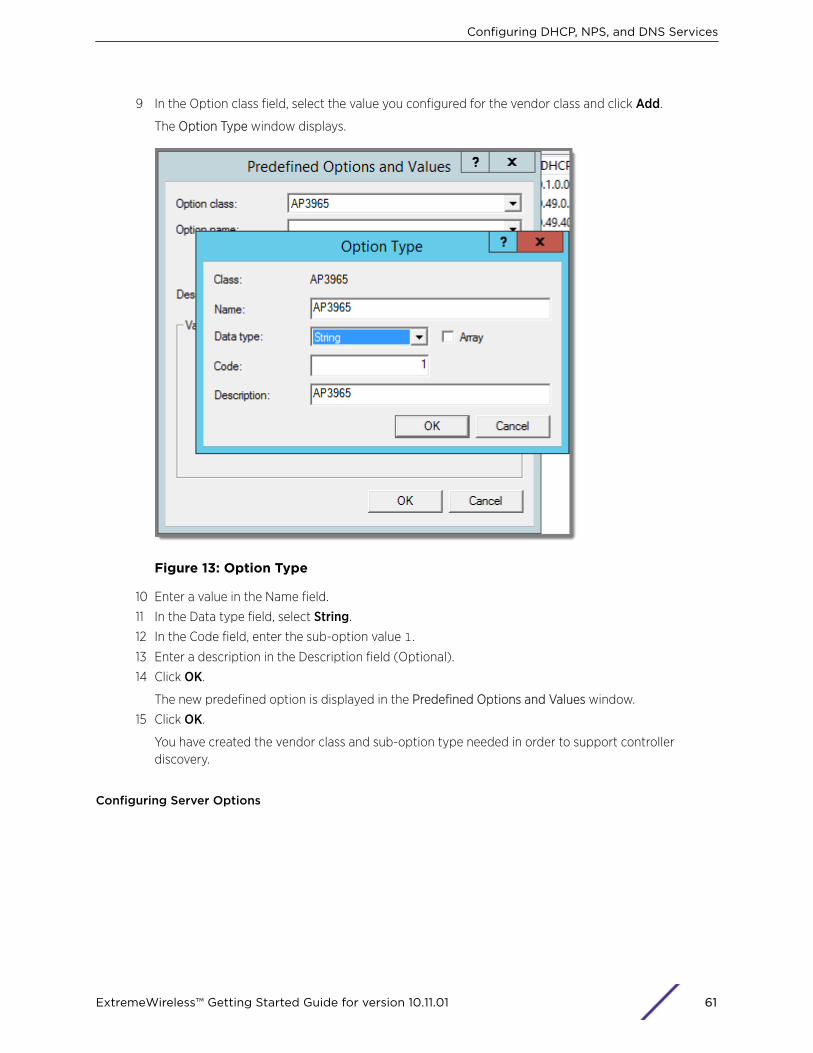
9 In the Option class field, select the value you configured for the vendor class and click Add.
The Option Type window displays.
Figure 13: Option Type
10 Enter a value in the Name field.
11 In the Data type field, select String.
12 In the Code field, enter the sub-option value 1.
13 Enter a description in the Description field (Optional).
14 Click OK.
The new predefined option is displayed in the Predefined Options and Values window.
15 Click OK.
You have created the vendor class and sub-option type needed in order to support controllerdiscovery.
Configuring Server Options
Configuring DHCP, NPS, and DNS Services
ExtremeWireless™ Getting Started Guide for version 10.11.01 61
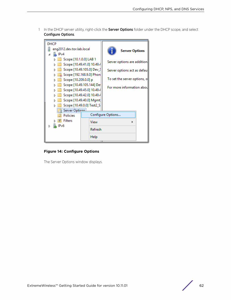
1 In the DHCP server utility, right-click the Server Options folder under the DHCP scope, and selectConfigure Options.
Figure 14: Configure Options
The Server Options window displays.
Configuring DHCP, NPS, and DNS Services
ExtremeWireless™ Getting Started Guide for version 10.11.01 62

2 Click the Advanced tab and configure the following parameters:
• Vendor Class. Select the vendor class that you plan to use. For example, AP3965.
• Available Options. Select the predefined 001 sub-option to assign to this scope.
• Data Entry. Enter the controller IP addresses to return to the APs. This is a comma-delimited list.
Figure 15: Server Options
3 Click OK.
DHCP Option 43 is now configured. This DHCP option is available for all the DHCP scopes that areconfigured in the DHCP server. When an AP requests vendor specific information, the DHCP serversends the ExtremeWireless Appliance IP addresses in Option 43 to the AP.
Configuring DHCP on a Red Hat Linux ServerYou can configure a DHCP server using the configuration file /etc/dhcpd.conf.
DHCP also uses the file /var/lib/dhcp/dhcpd.leases to store the client lease database.
The first step in configuring a DHCP server is to create the configuration file that stores the networkinformation for the clients. Global options can be declared for all clients, or options can be declared foreach client system.
Configuring DHCP, NPS, and DNS Services
ExtremeWireless™ Getting Started Guide for version 10.11.01 63
The configuration file can contain any extra tabs or blank lines for easier formatting. The keywords arenot case-sensitive and lines beginning with a hash mark (#) are considered comments.
To use the recommended mode, add the following line to the top of the configuration file:
ddns-update-style interim;
Read the dhcpd.conf man page for details about the different modes.
There are two types of statements in the configuration file:
• Parameters – State how to perform a task, whether to perform a task or what networkingconfiguration options to use to send to the client.
• Declarations – Describe the Topology of the network, describe the clients, provide addresses for theclients, or apply a group of parameters to a group of declarations.
Some parameters must start with the option keyword and are referred to as options. Options configureDHCP options; whereas, parameters configure values that are not optional or control how the DHCPserver behaves.
Parameters (including options) declared before a section enclosed in curly brackets {} are consideredglobal parameters. Global parameters apply to all the sections below it.
NoteIf you change the configuration file, the changes will not take effect until you restart the DHCPdaemon with the command service dhcpd restart.
The following is an example of a DHCP configuration on a Red Hat Linux server.
For Wireless AP Subnet
subnet 10.209.0.0 netmask 255.255.255.0 {option routers 10.209.0.2; ### This is the network’s default gateway address.option subnet-mask 255.255.255.0option domain-name xyznetworks.caoption domain-name servers 192.168.1.3, 207.236, 176.11range 10.209.0.3 10.209.0.40;default-lease-time 7200000 ###The figures are in seconds.option slp-directory-agent true 10.209.0.1, 10.209.0.3; ####The Wireless APsuse the SLP DA to discover the ExtremeWireless Appliance, and the mobilityagents use it to discover the mobility manager.authoritative;
Configuring DHCP Option 43 on a Linux Server
This section describes the configurations necessary on the Linux DHCP server to use DHCP option 43for ExtremeWireless Appliance discovery. Option 43 requires the following information:
• Vendor Class Identifier (VCI) — The VCI for an ExtremeWireless AP is HiPath <AP model name>. Table 9: AP Vendor Class Identifiers on page 55 lists the Vendor Class Identifiers for ExtremeNetworks APs.
• Option 43 sub-option code — The option 43 sub-option code for the ExtremeWireless APs is type 1(0x1).
• IP addresses of ExtremeWireless Appliances
Configuring DHCP, NPS, and DNS Services
ExtremeWireless™ Getting Started Guide for version 10.11.01 64
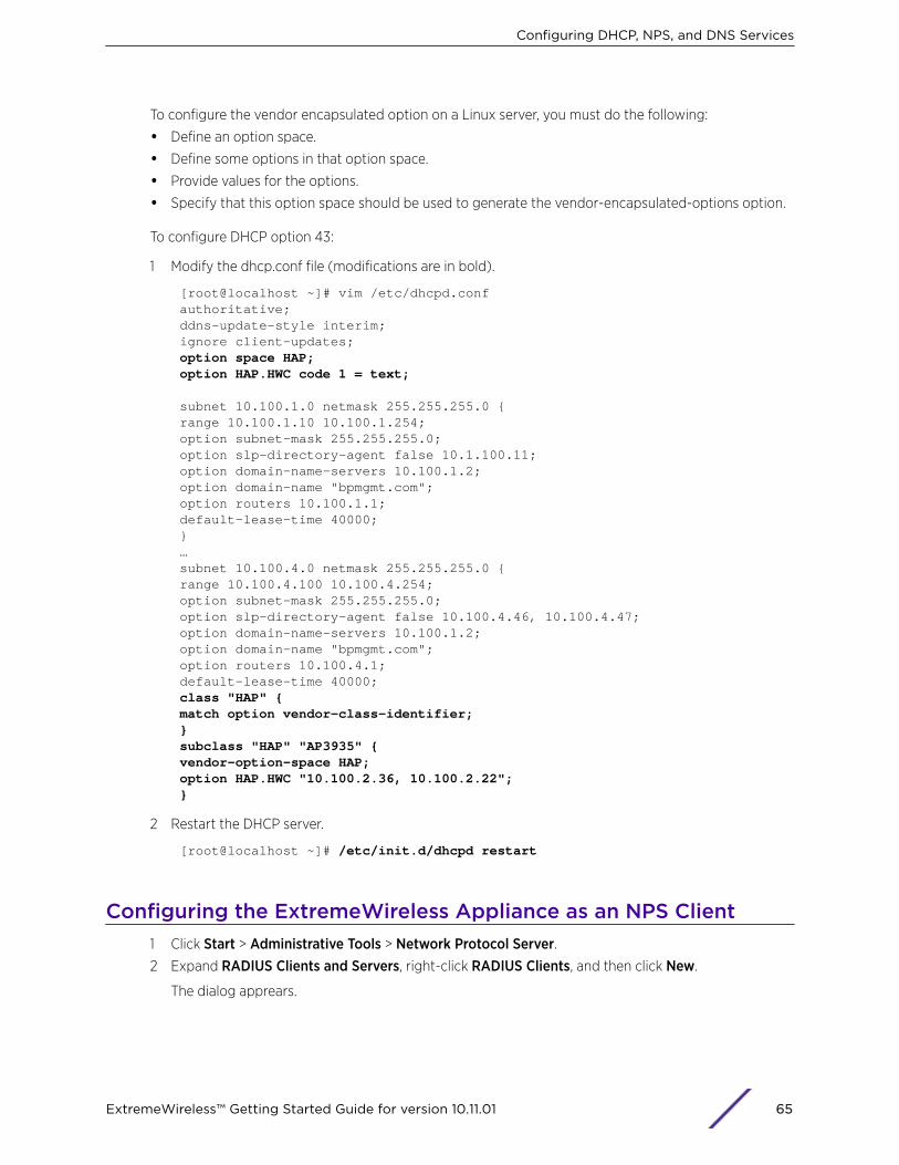
To configure the vendor encapsulated option on a Linux server, you must do the following:
• Define an option space.
• Define some options in that option space.
• Provide values for the options.
• Specify that this option space should be used to generate the vendor-encapsulated-options option.
To configure DHCP option 43:
1 Modify the dhcp.conf file (modifications are in bold).
[root@localhost ~]# vim /etc/dhcpd.confauthoritative;ddns-update-style interim;ignore client-updates;option space HAP;option HAP.HWC code 1 = text;
subnet 10.100.1.0 netmask 255.255.255.0 {range 10.100.1.10 10.100.1.254;option subnet-mask 255.255.255.0;option slp-directory-agent false 10.1.100.11;option domain-name-servers 10.100.1.2;option domain-name "bpmgmt.com";option routers 10.100.1.1;default-lease-time 40000;}…subnet 10.100.4.0 netmask 255.255.255.0 {range 10.100.4.100 10.100.4.254;option subnet-mask 255.255.255.0;option slp-directory-agent false 10.100.4.46, 10.100.4.47;option domain-name-servers 10.100.1.2;option domain-name "bpmgmt.com";option routers 10.100.4.1;default-lease-time 40000;class "HAP" {match option vendor-class-identifier;}subclass "HAP" "AP3935" {vendor-option-space HAP;option HAP.HWC "10.100.2.36, 10.100.2.22";}
2 Restart the DHCP server.
[root@localhost ~]# /etc/init.d/dhcpd restart
Configuring the ExtremeWireless Appliance as an NPS Client1 Click Start > Administrative Tools > Network Protocol Server.2 Expand RADIUS Clients and Servers, right-click RADIUS Clients, and then click New.
The dialog apprears.
Configuring DHCP, NPS, and DNS Services
ExtremeWireless™ Getting Started Guide for version 10.11.01 65

3 Configure the following parameters:
• Friendly name. Type the name that you want to assign to the ExtremeWireless Appliance
• Client address (IP or DNS). Type the IP address of the ExtremeWireless Appliance, and then clickVerify.
Figure 16: Verify Address
1 Click Resolve.
If the IP address is correct, it appears in the Search results text box.
2 Click OK.
• Shared Secret. Select a Shared Secret Template (Optional).
You can opt to enter a Shared Secret manually or have NPS generate the Shared Secret.
• Manual. Type a password that both the NPS server and the ExtremeWireless Appliance willuse to mutually authenticate. This password is case-sensitive. You can use alpha-numericcharacters. You must configure the same shared secret password for VNS Global Settings. Formore information, see the ExtremeWireless User Guide.
• Generate. Click Generate to have NPS generate the password. Not all servers support longgenerated secrets.
4 Click OK.
NPS Service ConfigurationMicrosoft Network Policy Server (NPS) can run as a Remote Authentication Dial-in User Service(RADIUS) server. You can use NPS for centralized authentication and accounting of multiple clientdevices. To install NPS on Windows Server 2012 R2, see http://support.microsoft.com. This sectionoutlines the following configuration procedures:
• Adding a New Network Policy on page 67
Configuring DHCP, NPS, and DNS Services
ExtremeWireless™ Getting Started Guide for version 10.11.01 66
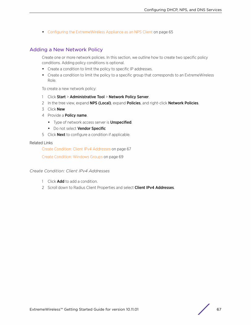
• Configuring the ExtremeWireless Appliance as an NPS Client on page 65
Adding a New Network PolicyCreate one or more network policies. In this section, we outline how to create two specific policyconditions. Adding policy conditions is optional.
• Create a condition to limit the policy to specific IP addresses.
• Create a condition to limit the policy to a specific group that corresponds to an ExtremeWirelessRole.
To create a new network policy:
1 Click Start > Administrative Tool > Network Policy Server.2 In the tree view, expand NPS (Local), expand Policies, and right-click Network Policies.
3 Click New4 Provide a Policy name.
• Type of network access server is Unspecified.
• Do not select Vendor Specific5 Click Next to configure a condition if applicable.
Related Links
Create Condition: Client IPv4 Addresses on page 67
Create Condition: Windows Groups on page 69
Create Condition: Client IPv4 Addresses
1 Click Add to add a condition.
2 Scroll down to Radius Client Properties and select Client IPv4 Addresses.
Configuring DHCP, NPS, and DNS Services
ExtremeWireless™ Getting Started Guide for version 10.11.01 67
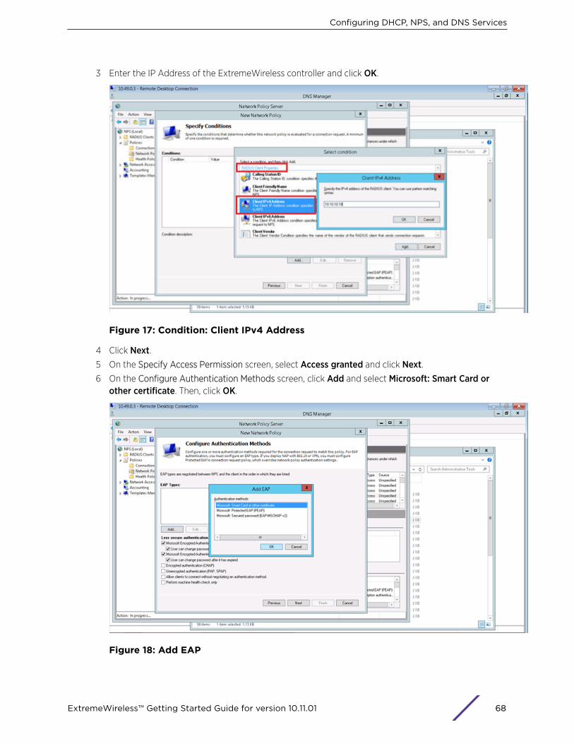
3 Enter the IP Address of the ExtremeWireless controller and click OK.
Figure 17: Condition: Client IPv4 Address
4 Click Next.5 On the Specify Access Permission screen, select Access granted and click Next.6 On the Configure Authentication Methods screen, click Add and select Microsoft: Smart Card or
other certificate. Then, click OK.
Figure 18: Add EAP
Configuring DHCP, NPS, and DNS Services
ExtremeWireless™ Getting Started Guide for version 10.11.01 68
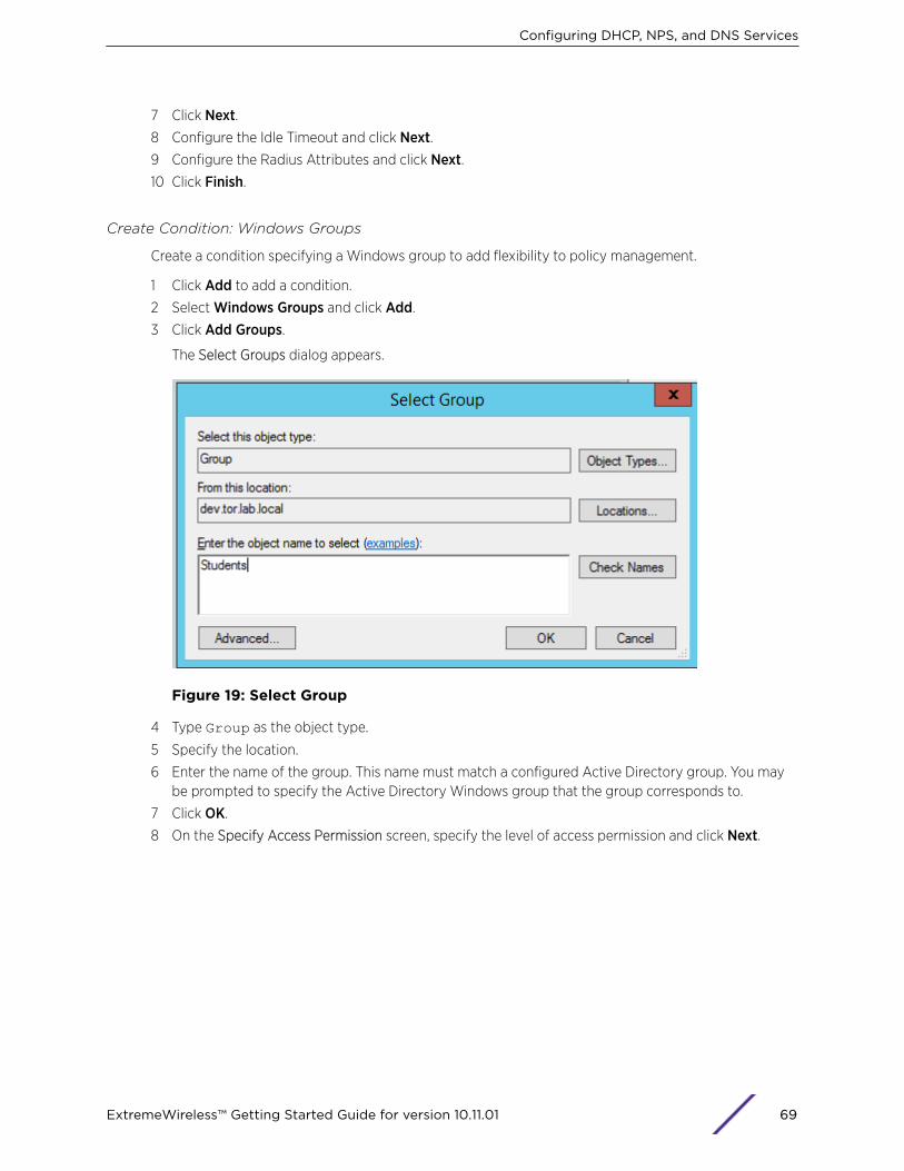
7 Click Next.8 Configure the Idle Timeout and click Next.9 Configure the Radius Attributes and click Next.10 Click Finish.
Create Condition: Windows Groups
Create a condition specifying a Windows group to add flexibility to policy management.
1 Click Add to add a condition.
2 Select Windows Groups and click Add.
3 Click Add Groups.
The Select Groups dialog appears.
Figure 19: Select Group
4 Type Group as the object type.
5 Specify the location.
6 Enter the name of the group. This name must match a configured Active Directory group. You maybe prompted to specify the Active Directory Windows group that the group corresponds to.
7 Click OK.
8 On the Specify Access Permission screen, specify the level of access permission and click Next.
Configuring DHCP, NPS, and DNS Services
ExtremeWireless™ Getting Started Guide for version 10.11.01 69
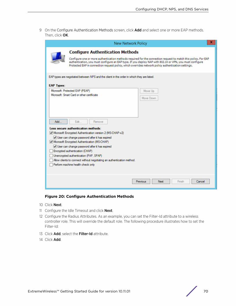
9 On the Configure Authentication Methods screen, click Add and select one or more EAP methods.Then, click OK.
Figure 20: Configure Authentication Methods
10 Click Next.11 Configure the Idle Timeout and click Next.12 Configure the Radius Attributes. As an example, you can set the Filter-Id attribute to a wireless
controller role. This will override the default role. The following procedure illustrates how to set theFilter-Id:
13 Click Add, select the Filter-Id attribute.
14 Click Add.
Configuring DHCP, NPS, and DNS Services
ExtremeWireless™ Getting Started Guide for version 10.11.01 70
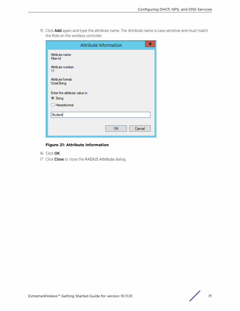
15 Click Add again and type the attribute name. The Attribute name is case sensitive and must matchthe Role on the wireless controller.
Figure 21: Attribute Information
16 Click OK.
17 Click Close to close the RADIUS Attribute dialog.
Configuring DHCP, NPS, and DNS Services
ExtremeWireless™ Getting Started Guide for version 10.11.01 71

18 Click Next.
Figure 22: Completing New Network Policy
19 Click Finish.
DNS Service ConfigurationThe domain name system (DNS) stores and associates many types of information with domain names,but most importantly, it translates domain names (computer hostnames) to IP addresses.
You must install DNS on Windows Server 2012 R2 according to the server documentation. Visit http://support.microsoft.com to learn how to install and configure DNS on Windows Server 2012 R2.
The instructions here are limited to Configuring DNS for Wireless APs Discovery.
For configuration on Linux, see Configuring DNS on a Linux Server on page 73.
Configuring DHCP, NPS, and DNS Services
ExtremeWireless™ Getting Started Guide for version 10.11.01 72
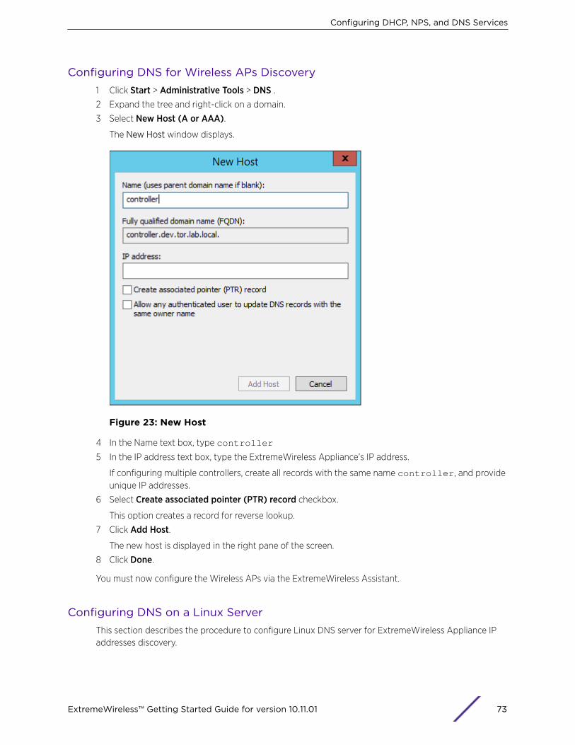
Configuring DNS for Wireless APs Discovery1 Click Start > Administrative Tools > DNS .2 Expand the tree and right-click on a domain.
3 Select New Host (A or AAA).
The New Host window displays.
Figure 23: New Host
4 In the Name text box, type controller
5 In the IP address text box, type the ExtremeWireless Appliance’s IP address.
If configuring multiple controllers, create all records with the same name controller, and provideunique IP addresses.
6 Select Create associated pointer (PTR) record checkbox.
This option creates a record for reverse lookup.
7 Click Add Host.
The new host is displayed in the right pane of the screen.
8 Click Done.
You must now configure the Wireless APs via the ExtremeWireless Assistant.
Configuring DNS on a Linux ServerThis section describes the procedure to configure Linux DNS server for ExtremeWireless Appliance IPaddresses discovery.
Configuring DHCP, NPS, and DNS Services
ExtremeWireless™ Getting Started Guide for version 10.11.01 73
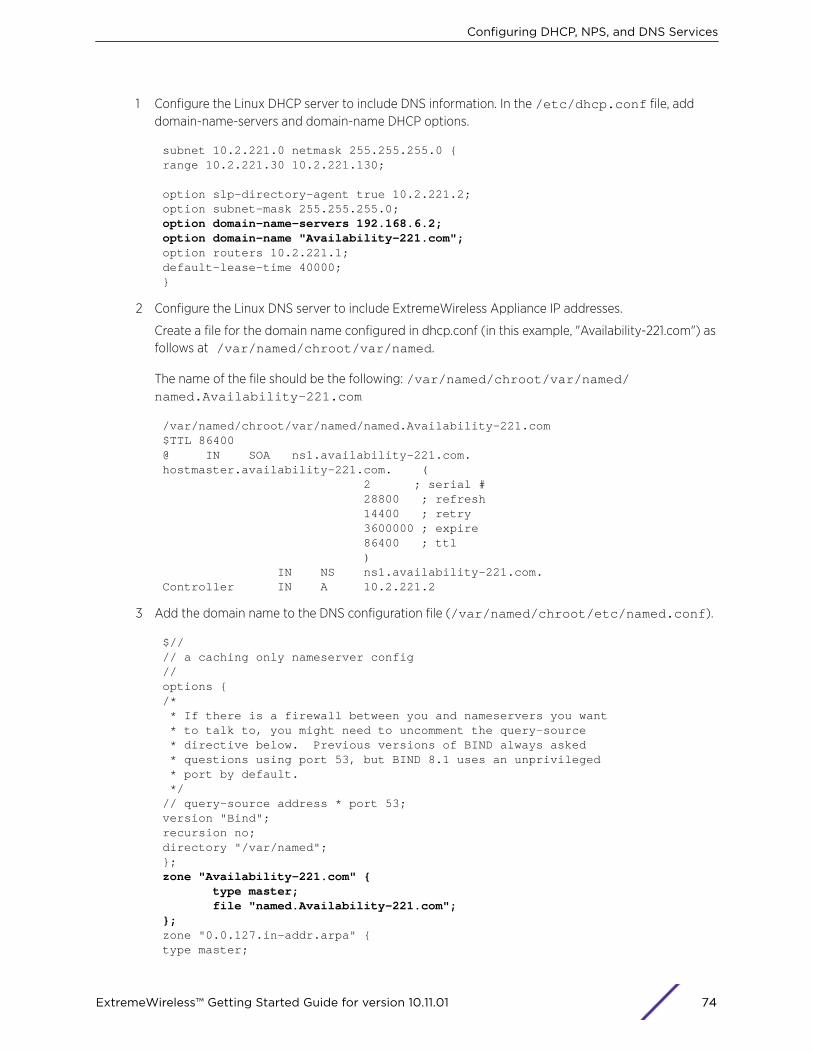
1 Configure the Linux DHCP server to include DNS information. In the /etc/dhcp.conf file, adddomain-name-servers and domain-name DHCP options.
subnet 10.2.221.0 netmask 255.255.255.0 {range 10.2.221.30 10.2.221.130;
option slp-directory-agent true 10.2.221.2;option subnet-mask 255.255.255.0;option domain-name-servers 192.168.6.2;option domain-name "Availability-221.com";option routers 10.2.221.1;default-lease-time 40000;}
2 Configure the Linux DNS server to include ExtremeWireless Appliance IP addresses.
Create a file for the domain name configured in dhcp.conf (in this example, "Availability-221.com") asfollows at /var/named/chroot/var/named.
The name of the file should be the following: /var/named/chroot/var/named/named.Availability-221.com
/var/named/chroot/var/named/named.Availability-221.com$TTL 86400@ IN SOA ns1.availability-221.com. hostmaster.availability-221.com. ( 2 ; serial # 28800 ; refresh 14400 ; retry 3600000 ; expire 86400 ; ttl ) IN NS ns1.availability-221.com. Controller IN A 10.2.221.2
3 Add the domain name to the DNS configuration file (/var/named/chroot/etc/named.conf).
$// // a caching only nameserver config// options { /* * If there is a firewall between you and nameservers you want * to talk to, you might need to uncomment the query-source * directive below. Previous versions of BIND always asked * questions using port 53, but BIND 8.1 uses an unprivileged * port by default. */// query-source address * port 53;version "Bind";recursion no;directory "/var/named";};zone "Availability-221.com" { type master; file "named.Availability-221.com";};zone "0.0.127.in-addr.arpa" { type master;
Configuring DHCP, NPS, and DNS Services
ExtremeWireless™ Getting Started Guide for version 10.11.01 74
file "named.local";allow-update { none; };
4 Confirm that DNS service is running.
ps -ef | grep namednamed 10023 1 0 Feb18 ? 00:00:00 /usr/sbin/named -u named -t /var/named/chrootroot 7687 7531 0 22:14 pts/982 00:00:00 grep named
5 Verify that the domain name is configured properly.
nslookup Controller.Availability-221.comServer: 127.0.0.1Address: 127.0.0.1#53
Name: Controller.Availability-221.comAddress: 10.2.221.2
Configuring DHCP, NPS, and DNS Services
ExtremeWireless™ Getting Started Guide for version 10.11.01 75


![Skaffold - storage.googleapis.com · [getting-started getting-started] Hello world! [getting-started getting-started] Hello world! [getting-started getting-started] Hello world! 5.](https://static.fdocuments.net/doc/165x107/5ec939f2a76a033f091c5ac7/skaffold-getting-started-getting-started-hello-world-getting-started-getting-started.jpg)