Extended Surface Heat Transfer and Thermal Stress in ...
21
Extended Surface Heat Transfer and Thermal Stress in Selected Annular Fins Ernesto Gutierrez-Miravete 1 Antonio Campo 2 1 Professor of Practice, Rensselaer Hartford, Hartford, CT, USA 2 University of San Antonio, San Antonio, TX, USA COMSOL 2020
Transcript of Extended Surface Heat Transfer and Thermal Stress in ...
Extended Surface Heat Transfer and Thermal Stress in Selected Annular Fins
Ernesto Gutierrez-Miravete1
Antonio Campo2
1 Professor of Practice, Rensselaer Hartford, Hartford, CT, USA2 University of San Antonio, San Antonio, TX, USA
COMSOL 2020

Enhanced Heat Transfer by Extended Surfaces
• Proper operation of engineering, industrial and scientific equipment require control of thermal conditions.
• Extended surfaces (fins) are commonly used to enhance the heat transfer rate and facilitate such control.
• In this presentation we describe the use of ComsolMultiphysics for the analysis of heat transfer and thermal stresses in annular fins and fin arrays of rectangular and parabolic profiles.
Steady state heat transfer in annular fins
• Fins are thin foils that are firmly attached to structures or process equipment at their base and use their extended surface to enhance heat transfer to or from the equipment they are attached to.
• Heat conduction in thin fins can be regarded approximately as unidimensional along the length of the fin but the approximation fails as the fins get thicker.
• Thermal energy is conducted radially along the fin and heat is exchanged by convection with the environment surrounding the extended surfaces of the fin.
• Exact solutions of the differential thermal energy balance equation for annular fins have been obtained only for annular fins of rectangular, hyperbolic and triangular profiles but the resulting expressions are cumbersome and their use is awkward in applications.
• No exact solutions seem to be available for the determination of thermal stresses in annular fins.

Examples of Annular FinsTHERMOFIN
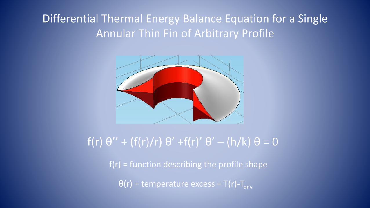
Differential Thermal Energy Balance Equation for a Single Annular Thin Fin of Arbitrary Profile
f(r) θ’’ + (f(r)/r) θ’ +f(r)’ θ’ – (h/k) θ = 0
f(r) = function describing the profile shape
θ(r) = temperature excess = T(r)-Tenv

Boundary Conditions
The boundary conditions commonly used to solve the isolated fin problem include the specification of the fin temperature at its base and zero heat loss at the fin tip, thus neglecting the thickness of the structure to which the fin is attached i.e.
T(rb) = Tb
-k (dT/dr)|rt = 0
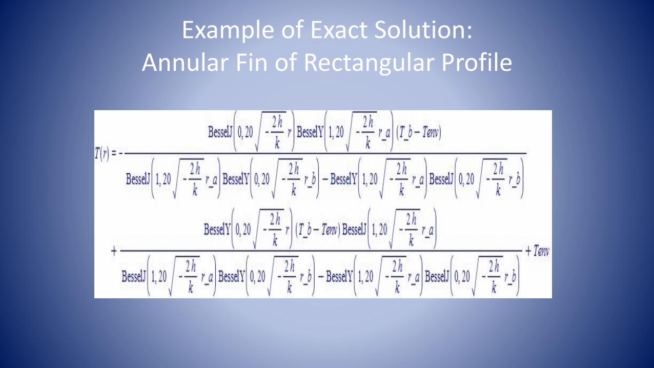
Example of Exact Solution:Annular Fin of Rectangular Profile

One Numerical Example (Krauss et al, Extended Surface Heat Transfer, pp. 29-32)
Input Data
• Fin Length = 0.075 m
• Inner radius = 0.05 m
• Outer radius = 0.125 m
• Fin Thickness = 0.0025 m
• Thermal Conductivity k = 40 W/m K
• Heat Transfer Coefficient h = 40 W/m2
• Base Temperature Tb = 110 oC
• Environment Temperature Tenv = 35 oC
Computed Results
• Exact Solution
Ttip = 48.546 oC
Q = 84.874 W
• Comsol Multiphysics
(392 DOF – Extra Coarse Mesh)
Ttip = 48.556 oC
Q = 84.626 W

Annular Fin Design Considerations I
• Rectangular profile fins are the simplest to use.
• However, fins with other profiles (triangular, hyperbolic, parabolic, …) increase heat exchange but exact solutions, if available, are cumbersome.
• Previous work has shown that a radial fin of parabolic profile and the same mass as a corresponding fin of rectangular profile with the same length exchanges more heat than the fin of rectangular profile.
• The value of the heat transfer coefficient over the extended surface is a critical parameter.

Annular Fin Design Considerations II
• A single fin is of limited usefulness; fin arrays with a large number of fins are normally used.
• Fins require space and material besides the one occupied by equipment and structures to which they are attached.
• Geometrical and thermal gradients around points of attachment of fins produce thermal stress concentrations and sharp stress gradients; this could be a problem.
• Fin design proposals can be easily and reliably investigated using the Finite Element Method.

Annular Fin Arrays(Thornhill, Nemati)

Thermo-Mechanics of Annular FinsGoverning Equations
• Heat Equation
• Equilibrium Equations
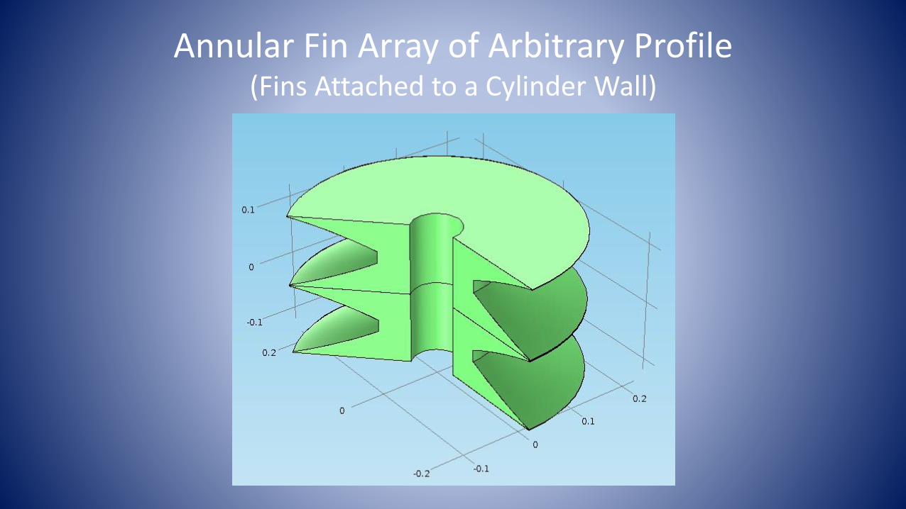
Annular Fin Array of Arbitrary Profile(Fins Attached to a Cylinder Wall)

Rectangular Fin ArrayComputed Temperature and Deformation

Parabolic Fin ArrayComputed Temperature and Deformation

Annular Fin ArraysTemperature and von Mises Stress

Convective Heat Flux From Extended Surface as a Function of Radial Distance from Base (Fins of Same Mass)
Rectangular Fin Parabolic Fin

Effect of Annular Fin Thickness on Heat Exchange from the Extended Surface
Fin Thickness at Base
2.5 mm (Rectangular Fin)
3.75 mm (“)
4.75 mm (“)
5.75 mm (“)
Heat Exchange (W)
79.08
83.08
92.84
101.28
The parabolic fin with base thickness of 3.75 mm contains the same amount of material as the 2.5 mm rectangular fin
but it dissipates 5% more heat
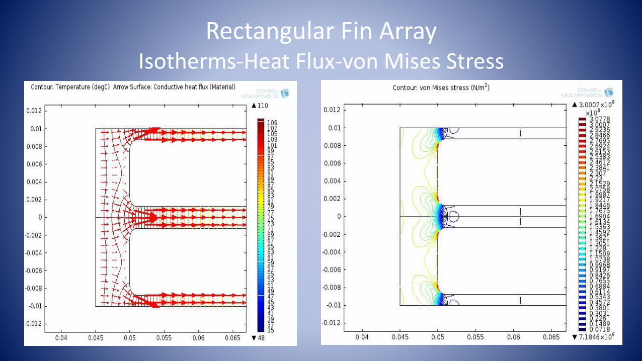
Rectangular Fin ArrayIsotherms-Heat Flux-von Mises Stress

Parabolic Fin ArrayIsotherms-Heat Flux-von Mises Stress

Conclusions
• Extended heat transfer phenomena in systems involving arrays of annular fins of arbitrary profile can be easily investigated using the finite element method in Comsol Multiphysics.
• The effect of temperature gradients on the thermal stresses in structures containing annular fins can also be determined with little additional effort.