Extended Stress Intensity Factor Concepts
166
Chapter 2 Extended Stress Intensity Factor Concepts Abstract The stress intensity factor concept for describing the stress field at pointed crack or slit tips is well known from fracture mechanics. It is substantially extended here in two directions. One extension refers to pointed V-notches with stress intensities depending on the notch opening angle. The loading mode related notch stress intensity factors K 1 , K 2 and K 3 are introduced. Another extension refers to rounded notches with crack shape or V-notch shape in two variants: parabolic, elliptic or hyperbolic notches (‘blunt notches’) on the one hand and root hole notches (‘keyholes’ when considering crack shapes) on the other hand. Here, the loading mode related generalised notch stress intensity factors K 1q , K 2q and K 3q are defined. The concepts of elastic stress intensity factor, notch stress intensity factor and generalised notch stress intensity factor are extended into the range of elastic-plastic (work-hardening) or perfectly plastic notch tip or notch root behaviour. Here, the plastic notch stress intensity factors K 1p , K 2p and K 3p are of relevance. The original stress intensity factor concept is also transferred from cracks or slits to rigid thin inclusions. Contents 2.1 Survey of Chapter Contents ........................................................................................... 103 2.2 Original Stress Intensity Factor Concept ....................................................................... 104 2.2.1 Survey of Section Contents ................................................................................ 104 2.2.2 Basic Crack Tip Loading Modes ....................................................................... 105 2.2.3 Asymptotic Stress Field near Crack Tips .......................................................... 106 2.2.4 Higher Order Non-Singular Stress Terms ......................................................... 108 2.2.5 Limit Value Formulae for SIFs, T-Stress and S-Stress .................................... 109 2.2.6 J-Integral Expressed by SIFs and T-Stress ........................................................ 110 2.2.7 General SIF Formulae ........................................................................................ 111 2.2.8 SIFs at Spot-Welded Lap Joints ........................................................................ 113 2.2.9 Equivalent SIFs under Mixed Mode Loading Conditions ................................ 122 2.2.10 Endurable Stress Intensity Factors ..................................................................... 127 2.2.11 Conclusions ......................................................................................................... 129 D. Radaj D. Radaj and M. Vormwald, Advanced Methods of Fatigue Assessment, DOI: 10.1007/978-3-642-30740-9_2, Ó Springer-Verlag Berlin Heidelberg 2013 101
Transcript of Extended Stress Intensity Factor Concepts
Chapter 2Extended Stress Intensity Factor Concepts
Abstract The stress intensity factor concept for describing the stress field atpointed crack or slit tips is well known from fracture mechanics. It is substantiallyextended here in two directions. One extension refers to pointed V-notches withstress intensities depending on the notch opening angle. The loading mode relatednotch stress intensity factors K1, K2 and K3 are introduced. Another extensionrefers to rounded notches with crack shape or V-notch shape in two variants:parabolic, elliptic or hyperbolic notches (‘blunt notches’) on the one hand and roothole notches (‘keyholes’ when considering crack shapes) on the other hand. Here,the loading mode related generalised notch stress intensity factors K1q, K2q andK3q are defined. The concepts of elastic stress intensity factor, notch stressintensity factor and generalised notch stress intensity factor are extended into therange of elastic-plastic (work-hardening) or perfectly plastic notch tip or notch rootbehaviour. Here, the plastic notch stress intensity factors K1p, K2p and K3p are ofrelevance. The original stress intensity factor concept is also transferred fromcracks or slits to rigid thin inclusions.
Contents
2.1 Survey of Chapter Contents ........................................................................................... 1032.2 Original Stress Intensity Factor Concept....................................................................... 104
2.2.1 Survey of Section Contents................................................................................ 1042.2.2 Basic Crack Tip Loading Modes ....................................................................... 1052.2.3 Asymptotic Stress Field near Crack Tips .......................................................... 1062.2.4 Higher Order Non-Singular Stress Terms ......................................................... 1082.2.5 Limit Value Formulae for SIFs, T-Stress and S-Stress .................................... 1092.2.6 J-Integral Expressed by SIFs and T-Stress........................................................ 1102.2.7 General SIF Formulae ........................................................................................ 1112.2.8 SIFs at Spot-Welded Lap Joints ........................................................................ 1132.2.9 Equivalent SIFs under Mixed Mode Loading Conditions ................................ 1222.2.10 Endurable Stress Intensity Factors ..................................................................... 1272.2.11 Conclusions ......................................................................................................... 129
D. Radaj
D. Radaj and M. Vormwald, Advanced Methods of Fatigue Assessment,DOI: 10.1007/978-3-642-30740-9_2, � Springer-Verlag Berlin Heidelberg 2013
101

2.3 Notch Stress Intensity Factor Concept .......................................................................... 1302.3.1 Survey of Section Contents................................................................................ 1302.3.2 Stress Field near Pointed V-Notches ................................................................. 1312.3.3 Transverse Singular Effect at In-Plane Shear-Loaded V-Notches ................... 1362.3.4 NSIF Values of V-Notches and Weld Toe Notches ......................................... 1402.3.5 Relationship between Structural Stress and NSIF for Welded Joints .............. 1452.3.6 Empirical Mixed-Mode Failure Criterion for Welded Joints ........................... 1492.3.7 Endurable NSIFs of Fatigue-Loaded Welded Joints......................................... 1522.3.8 Endurable J-Integral for Fatigue-Loaded Welded Joints .................................. 1542.3.9 Conclusions ......................................................................................................... 156
2.4 Generalised Notch Stress Intensity Factor Concept...................................................... 1562.4.1 Survey of Section Contents................................................................................ 1562.4.2 Stress Field at Blunt V-Notches Subjected to Tensile and In-Plane
Shear Loading..................................................................................................... 1572.4.3 Stress Field at Blunt V-Notches Subjected to Out-of-Plane Shear Loading ... 1602.4.4 Generalised Notch Stress Intensity Factors ....................................................... 1612.4.5 Evaluation Examples for Stresses at Blunt V-Notches..................................... 1652.4.6 Stress Field at V-Notches with Root Hole ........................................................ 1762.4.7 Generalised NSIFs of Parabolic and Keyhole Notches in Comparison ........... 1842.4.8 The T-Stress Effect in Rounded Notch Configurations .................................... 1872.4.9 Application of the Generalised NSIF Concept to Round Bars
with Shoulder Fillet ............................................................................................ 1932.4.10 Fatigue Limit Expressed by Notch Stress Intensity Factors............................. 1962.4.11 Conclusions ......................................................................................................... 198
2.5 Plastic Notch Stress Intensity Factor Concept .............................................................. 1992.5.1 Survey of Section Contents................................................................................ 1992.5.2 Deformation Theory of Plasticity Founding the HRR Fields........................... 2002.5.3 Elastic-Plastic Fields at Tensile Loaded V-Notches ......................................... 2022.5.4 Elastic-Plastic Fields at Tensile Loaded V-Notches, SED-Based Approach ... 2102.5.5 Elastic-Plastic Fields at Out-of-Plane Shear-Loaded Parabolic Notches ......... 2132.5.6 Elastic-Plastic Fields at Out-of-Plane Shear-Loaded Pointed V-Notches ........ 2152.5.7 Uniform Analysis of Nonlinear Fields at Out-of-Plane
Shear-Loaded V-Notches.................................................................................... 2222.5.8 Plastic Zone Related to Elastic Higher Order Singularities ............................. 2262.5.9 Neuber Rule Including the Influence of the Notch Opening Angle ................ 2282.5.10 Analytical Description of Elastic-Plastic Material Behaviour .......................... 2332.5.11 Conclusions ......................................................................................................... 241
2.6 Stress Intensity Factor Concept for Rigid Inclusions ................................................... 2422.6.1 Survey of Section Contents................................................................................ 2422.6.2 Basic Loading Modes at Rigid Thin Inclusion Tips......................................... 2432.6.3 Asymptotic Stress Field Close to Rigid Thin Inclusion Tips........................... 2442.6.4 Limit Value Formulae for Stress Intensity Factors at Rigid
Thin Inclusion Tips ............................................................................................ 2482.6.5 Example of Stress Intensity Factor Evaluation ................................................. 2502.6.6 Outlook to Wedge-Shaped Rigid Inclusion....................................................... 2512.6.7 Conclusions ......................................................................................................... 252
References................................................................................................................................ 257
102 2 Extended Stress Intensity Factor Concepts
2.1 Survey of Chapter Contents
The stress intensity factor concept has originally been developed in the context offracture mechanics. For fracture phenomena, both brittle fracture and fatiguefailure, the asymptotic singular stress field at the pointed crack or slit tip is mostimportant. The stress level around the singularity is described by the stressintensity factor (SIF), possibly superimposed by the crack-parallel non-singularT-stress. In certain cases (e.g. thin-sheet lap joints), it is necessary, also to takehigher order terms of the stress field approximation into account.
The local three-dimensional stress singularity at a definite point of the crack orslit front can generally be described by superimposition of three two-dimensionalstress singularities corresponding to three independent loading or opening modesof the crack tip: transverse tensile loading (mode I), in-plane shear loading (modeII) and out-of-plane shear loading (mode III). The appertaining SIFs are KI, KII andKIII. Non-singular stresses may be superimposed: crack-parallel stresses (theT-stress) as well as normal stresses and symmetric shear stresses in the crack frontdirection. In special cases, the separation of the elementary crack tip loadingmodes is not possible, coupling effects together with transverse singular effects areoccurring, e.g. where the crack front butts on a free surface.
The SIF concept has been substantially extended in two directions. Oneextension refers to pointed V-notches with stress intensities depending on thenotch opening angle. Here, the loading mode related notch stress intensity factors(NSIFs) are K1, K2 and K3. Another extension refers to rounded notches with crackshape or V-notch shape in two variants: parabolic, elliptic or hyperbolic notches(‘blunt notches’) on the one hand and root hole notches (‘keyholes’ when con-sidering crack shapes) on the other hand. The notch stresses remain finite in thiscase, but their angular and radial distribution is linked to that of the correspondingpointed notches. Here, the loading mode related generalised NSIFs are K1q, K2q
and K3q. They are slightly larger than K1, K2 and K3, their value increases withreduced notch severity.
The elastic SIF, NSIF and generalised NSIF concepts may be extended into therange of elastic-plastic (work-hardening) or perfectly plastic notch tip or notch rootbehaviour. Here, the plastic NSIFs K1p, K2p and K3p are of relevance.
Further extensions of the SIF concepts are documented in the literature. Theoriginal SIF concept may be transferred from cracks or slits to rigid thin inclu-sions, from pointed V-notches to pointed rigid inclusions with V-notch shape andfrom blunt V-notches to the corresponding rounded rigid inclusions. Anotherextension is the bimaterial wedge problem with inclusion of interface crackconfigurations.
In Sect. 2.2, the original stress intensity factor concept is reviewed, referring tothe stress field near crack tips, with application to slit tips in welded joints.
In Sect. 2.3, the notch stress intensity factor concept is summarised, referring tothe stress field near pointed V-notch tips, with application to fillet-welded joints.
2.1 Survey of Chapter Contents 103
In Sect. 2.4, the generalised notch stress intensity factor concept is described,referring to the stress field at blunt V-notch tips and at root hole V-notch tips, withapplication to round bars with shoulder fillets.
In Sect. 2.5, plastic notch stress intensity factors are introduced for describingthe stress and strain field at pointed V-notch tips and at parabolic notch tips. A newversion of the Neuber rule accounting for the influence of the notch opening angleis presented.
In Sect. 2.6, the stress intensity factor concept is applied to rigid thin inclusions,with one example of SIF evaluation.
The bimaterial wedge problem with inclusion of interface crack configurationscannot be presented within the available space of this book. Reference is madeinstead to the early basic solutions (Hein and Erdogan 1971; Bogy 1971) and to arecent comprehensive study on asymptotic near-field analyses of plane multi-material joints (Sator 2010). Typical applications are interface cracks or cracksbutting on the interface, the interface itself butting on a unnotched surface, on acorner-notched surface or on a more generally V-notched surface. A well knownspecial problem is the bearing pressure between a plane rigid stamp and a planeelastic continuum.
2.2 Original Stress Intensity Factor Concept
2.2.1 Survey of Section Contents
The basic formulation of the SIF concept is reviewed. Basic is the description ofthe singular and non-singular stress field in the vicinity of a crack tip or slit tip.The three-dimensional stress state at any point of the crack or slit front is separatedinto the three two-dimensional singular loading modes I, II and III and into threenon-singular modes (T-stress, S-stress and front-parallel normal stress). A couplingof singular modes together with transverse singular effects may occur where thecrack or slit front butts on a free surface.
The stress field equations in the vicinity of crack or slit tips are presented andthe corresponding SIFs, T-stress and S-stress are defined. These characteristicparameters are specified for the joint face edge of seam-welded and spot-weldedlap joints proceeding from the linearised structural stresses which suppress thesingularity completely. Lap joints with equal and unequal plate thickness,respectively, are considered.
Equivalent SIFs are defined, referring to failure under mixed-mode loadingconditions. Endurable SIFs for spot-welded lap joints are finally given, both in theform of a threshold value and in the form of a K–N curve with a defined, suffi-ciently low scatter range.
104 2 Extended Stress Intensity Factor Concepts

The expositions are based on readily available text books on fracture mechanicsand on special publications. A list of symbols and a list of references are found atthe end of Chap. 2.
2.2.2 Basic Crack Tip Loading Modes
The stress intensity factor concept originates from fracture mechanics. For fracturephenomena, both brittle fracture and fatigue failure, the local stress field close tothe crack tip is decisive. The stresses rise to a singularity at the pointed crack tip.The intensity of this singularity is dependent on the magnitude of the relevantstructural stresses.
The local three-dimensional stress field at a definite point of the crack front maygenerally be separated into two-dimensional stress fields which are superimposed:three loading modes with singular stresses and three loading modes withnon-singular stresses. The singular loading modes comprise transverse tensileloading (mode I), in-plane shear loading (mode II) and out-of-plane shear loading(mode III), Fig. 2.1. The non-singular loading modes consist of crack-paralleltensile or compressive loading (mode 0I), crack-front-parallel tensile or
Fig. 2.1 Basic singular loading modes I (a), II (b) and III (c) of cracks; planar crack in theinfinite plate; plane and antiplane strain fields; arrows designate remote boundary or crack flankstresses; (Radaj and Zhang 1993(1))
2.2 Original Stress Intensity Factor Concept 105

compressive loading (mode 0II) and crack-front-parallel shear loading (mode 0III),Fig. 2.2.
In exceptional cases, coupling effects may occur locally between the mode-related singularities within locally three-dimensional configurations. One typicalexample is the crack tip in a plate of finite thickness subjected to in-plane shearloading. A transverse shear stress singularity is generated locally underneath theplate surface. Further details can be found in Sect. 2.3.3.
2.2.3 Asymptotic Stress Field near Crack Tips
The three basic loading modes with singular stresses at the crack tip produce thefollowing asymptotic stress distribution around the crack tip (Westergaard 1939;Sneddon 1946; Irwin 1957; Williams 1957), Fig. 2.3:
rij ¼1ffiffiffiffiffiffiffiffi
2prp KIfI;ijðhÞ þ KIIfII;ijðhÞ þ KIIIfIII;kzðhÞ
� �
ði, j ¼ x; y and k ¼ x; y or i, j ¼ r; h and k ¼ r; hÞð2:1Þ
The mode-related stress intensity factors (SIFs) KI, KII and KIII depend on themagnitude of the load, the crack length and further geometrical parameters of theconsidered configuration. The mode-related angle-dependent functions fI,ij, fII,ij,fIII,iz describe the angular distribution of the stresses at the crack tip. The relationshipabove is strictly valid for r ! 0 and approximately valid for values of r which aresmall in relation to the crack length and other geometrical parameters of theconfiguration.
These are the asymptotic stresses in the three singular loading modes, given inpolar coordinates:
Fig. 2.2 Basic non-singular loading modes 0I (a), 0II (b) and 0III (c) of cracks; planar crack inthe infinite plate; plane and antiplane strain fields; arrows designate remote boundary stresses;(Radaj and Zhang 1993(1))
106 2 Extended Stress Intensity Factor Concepts

Mode I (transverse tensile loading):
rr
rh
srh
8
<
:
9
=
;
¼ KI
4ffiffiffiffiffiffiffiffi
2prp
5 cos h=2� cos 3h=23 cos h=2þ cos 3h=2
sin h=2þ sin 3h=2
8
<
:
9
=
;
ð2:2Þ
rz ¼ 0 ðplane stressÞ
rz ¼ mðrr þ rhÞ ¼2mKIffiffiffiffiffiffiffiffi
2prp cos
h2ðplane strainÞ
ð2:3Þ
Mode II (in-plane shear loading):
rr
rh
srh
8
<
:
9
=
;
¼ KII
4ffiffiffiffiffiffiffiffi
2prp
�5 sin h=2þ 3 sin 3h=2�3 sin h=2� 3 sin 3h=2
cos h=2þ 3 cos 3h=2
8
<
:
9
=
;
ð2:4Þ
rz ¼ 0 ðplane stressÞ
rz ¼ mðrr þ rhÞ ¼ �2mKIIffiffiffiffiffiffiffiffi
2prp sin
h2ðplane strainÞ
ð2:5Þ
Mode III (out-of-plane shear loading):
srz
sh z
� �
¼ KIIIffiffiffiffiffiffiffiffi
2prp sin h=2
cos h=2
� �
ð2:6Þ
Fig. 2.3 Cartesian (a) and polar (b) coordinate systems with correspondingly defined stresses atthe crack tip; (Lazzarin and Tovo 1998)
2.2 Original Stress Intensity Factor Concept 107

2.2.4 Higher Order Non-Singular Stress Terms
The Eqs. (2.1–2.6) above represent asymptotic or first order approximations of thestress field around the singularity at the crack tip. They deviate from the exact solutionwith increasing distance from the crack tip. The complete solution for the stress fieldis represented by an infinite series expansion based on eigenvalues and eigenfunctionsresulting in non-singular higher order stress terms (Williams 1952, 1957).
The boundary condition of load-free crack or slit flanks (h = ±p), introducedinto the general complex stress functions, results in a homogeneous equationsystem. Nontrivial solutions exist for the coefficient determinant being zero,resulting in identical eigenvalues in the three loading modes:
sin 2kp ¼ 0 ! k ¼ n
2ðn ¼ 1; 2; 3; . . .Þ ð2:7Þ
The stresses are expressed by an infinite series of the corresponding eigen-functions (nomenclature after Gross and Seelig 2001):
rij ¼ r�1=2rð1Þij ðhÞ þ rð2Þij ðhÞ þ r1=2rð3Þij ðhÞ þ rrð4Þij ðhÞ þ . . . ði; j ¼ r; hÞ ð2:8Þ
skz ¼ r�1=2sð1Þkz ðhÞ þ sð2Þkz ðhÞ þ r1=2sð3Þkz ðhÞ þ rsð4Þkz ðhÞ þ . . . ðk ¼ r; hÞ ð2:9Þ
The stress field equation rij can be split into symmetric and antimetric parts inrespect of h, the symmetric part connected with mode I loading, the antimetric partwith mode II loading. The stress field equation skz is related to mode III loading.
The first order terms define the stress singularity at the crack tip (r = 0). Theycontain the SIFs KI, KII and KIII. The second order terms define a uniform non-singular stress at the crack tip, the tensile or compressive stress directed in crackdirection named ‘T-stress’ (Larsson and Carlsson 1973) and the symmetric shearstress in crack front direction which may be named ‘S-stress’ in conformity withthe T-stress.
These parameters control the stress field close to the crack tip (the ‘near-field’),now written in the usual nomenclature up to the second term:
rð1;2ÞI;ij ¼KIffiffiffiffiffiffiffiffi
2prp f ð1ÞI;ij ðhÞ þ Tf ð2ÞT;ijðhÞ ð2:10Þ
rð1;2ÞII;ij ¼KIIffiffiffiffiffiffiffiffi
2prp f ð1ÞII;ijðhÞ ð2:11Þ
sð1;2ÞIII;kz ¼KIIIffiffiffiffiffiffiffiffi
2prp f ð1ÞIII;kzðhÞ þ Sf ð2ÞS;kzðhÞ ð2:12Þ
The stress terms of higher than second order converge to zero for r ! 0, butmay be important for larger values of r. Under certain conditions, e.g. a low sheetthickness in lap joints, the range of r, where the second order approximation isappropriate, may be very small (e.g. r = 0.01 mm in the tensile-shear specimen
108 2 Extended Stress Intensity Factor Concepts

with a plate thickness of 1 mm). Then, higher order approximations are needed.The stress equations for mode I and II loading have been derived up to the seventhterm represented by r5/2 (Berto and Lazzarin 2010).
A possible misunderstanding should immediately be removed. The higher orderterms do not describe the stress field in the total structure. The series developmentsin Eqs. (2.8) and (2.9) are valid only within a certain distance from the slit tip,smaller than the nearest external boundary.
The T-stress r0 corresponds to the loading mode 0I in Fig. 2.2, the S-stress s�0to the loading mode 0III. The uniform normal stress r�0 in the direction of the crackfront produced by mode 0II loading needs no special comment.
The T-stress results in the following polar stress components:
rr
rh
srh
8
<
:
9
=
;
T
¼ Tcos2 hsin2 h
�0:5 sin 2h
8
<
:
9
=
;
ð2:13Þ
rz ¼ mT ðplane strainÞ ð2:14Þ
The corresponding expression for the S-stress is:
srz
sh z
� �
S
¼ Scos h� sin h
� �
ð2:15Þ
2.2.5 Limit Value Formulae for SIFs, T-Stress and S-Stress
The SIFs KI, KII and KIII may be determined based on Eqs. (2.10–2.12) from thefollowing limit value formulae which consider the predominant stresses in theligament (h = 0):
KI ¼ limr!0
ffiffiffiffiffiffiffiffi
2prp
rh ð2:16Þ
KII ¼ limr!0
ffiffiffiffiffiffiffiffi
2prp
srh ð2:17Þ
KIII ¼ limr!0
ffiffiffiffiffiffiffiffi
2prp
sh z ð2:18Þ
Alternatively, limit values of the predominant displacements of the crack flanksmay be evaluated. Any other non-vanishing stress or displacement component forthe same or other values of h may be used in the limit value formulae.
The limit conditions above may be applied to analytical stress field solutionsand their series expansion or to numerical solutions based on the finite element orboundary element method. In the latter case, the limit value evaluation is facili-tated by plotting the stress or displacement components over the distance r fromthe crack tip in log–log scales. The first order stress approximations appear as
2.2 Original Stress Intensity Factor Concept 109

decreasing straight lines with the gradient corresponding to 1/r1/2. The SIFs caneasily be calculated from these approximations.
T-stress and S-stress may also be determined from analytical solutions afterseries expansion of the stress field. In the case of numerical modelling, the T-stressis usually determined as the medium value of the tensile or compressive stressesacting in the two flank sides of the crack. In general, this crack-parallel stress isevaluated in the midsection of the (internal) crack. It has the same sign and valueon both sides of the crack, whereas the corresponding stresses from mode IIloading have opposite signs (Williams 1957).
Using another method, the T-stress results from the difference in the stresses rr
and rh acting in the ligament close to the crack tip (Lazzarin et al. 2009):
T ¼ rr � rh ðh ¼ 0; r ! 0Þ ð2:19Þ
whereas Mode II loading has no effect on these stresses.The S-stress is determined as the medium of the shear stresses acting along the
crack front in the plane normal to the ligament at r ! 0. It is the symmetric mode0III shear stress component.
The parameters T and S are defined for r ! 0, but may be extended to the nearfield r [ 0, T(r) and S(r), with a linear dependency on r.
2.2.6 J-Integral Expressed by SIFs and T-Stress
The line integral J (Rice 1968), designed for describing the fracture behaviour innonlinear-elastic materials, can successfully be applied with certain restrictions tothe elastic-plastic fracture behaviour. Rice has shown that the nonlinear energyrelease rate can be written as a path-independent line integral J around the cracktip. It has also been shown that the J-integral uniquely characterises the stress andstrain field close to the crack tip (Hutchinson 1968; Rice and Rosengren 1968).Thus the J-integral is both an energy parameter and a stress intensity parameter(Anderson 1995).
In its simplified linear-elastic form, the J-integral may be used to determine SIFson the basis of remote boundary conditions chosen on the integration path. Viceversa, the J-integral may be determined based on the available SIFs and T-stress.
It can be shown that, under linear-elastic conditions, the J-integral is equal tothe energy release rate, provided coplanar crack propagation can be assumed.Then, the total J is the sum of the mode-related J-values, JI, JII and JIII:
J ¼ JI þ JII þ JIII ¼K2
I
E0þ K2
II
E0þ K2
III
2G
E0 ¼ E ðplane stressÞ; E0 ¼ E
1� m2ðplane strainÞ; G ¼ E
2ð1þ mÞ
ð2:20Þ
where E is the modulus of elasticity and G the shear modulus.
110 2 Extended Stress Intensity Factor Concepts
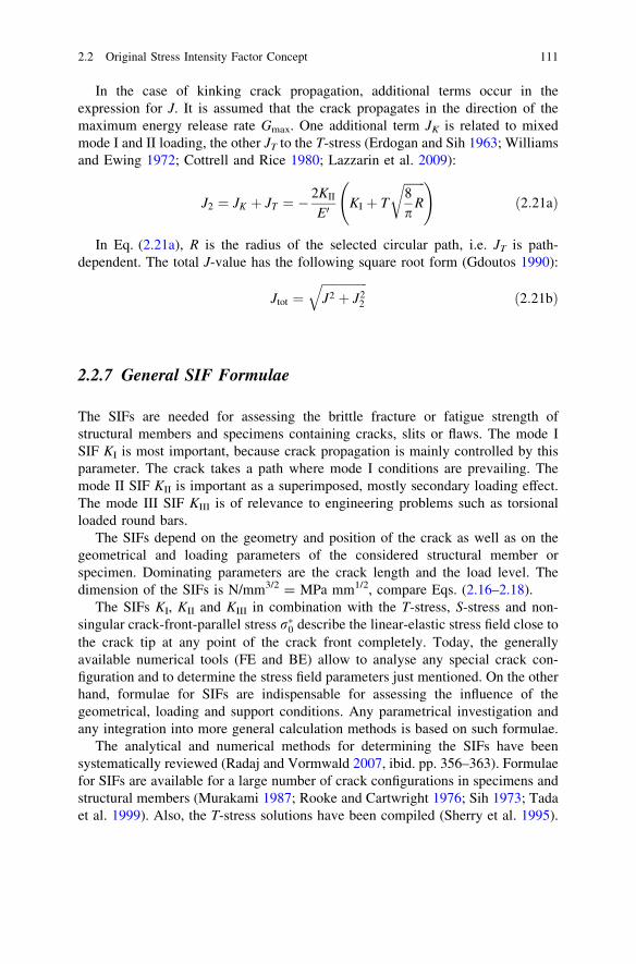
In the case of kinking crack propagation, additional terms occur in theexpression for J. It is assumed that the crack propagates in the direction of themaximum energy release rate Gmax. One additional term JK is related to mixedmode I and II loading, the other JT to the T-stress (Erdogan and Sih 1963; Williamsand Ewing 1972; Cottrell and Rice 1980; Lazzarin et al. 2009):
J2 ¼ JK þ JT ¼ �2KII
E0KI þ T
ffiffiffiffiffiffiffi
8p
R
r
!
ð2:21aÞ
In Eq. (2.21a), R is the radius of the selected circular path, i.e. JT is path-dependent. The total J-value has the following square root form (Gdoutos 1990):
Jtot ¼ffiffiffiffiffiffiffiffiffiffiffiffiffiffiffi
J2 þ J22
q
ð2:21bÞ
2.2.7 General SIF Formulae
The SIFs are needed for assessing the brittle fracture or fatigue strength ofstructural members and specimens containing cracks, slits or flaws. The mode ISIF KI is most important, because crack propagation is mainly controlled by thisparameter. The crack takes a path where mode I conditions are prevailing. Themode II SIF KII is important as a superimposed, mostly secondary loading effect.The mode III SIF KIII is of relevance to engineering problems such as torsionalloaded round bars.
The SIFs depend on the geometry and position of the crack as well as on thegeometrical and loading parameters of the considered structural member orspecimen. Dominating parameters are the crack length and the load level. Thedimension of the SIFs is N/mm3/2 = MPa mm1/2, compare Eqs. (2.16–2.18).
The SIFs KI, KII and KIII in combination with the T-stress, S-stress and non-singular crack-front-parallel stress r�0 describe the linear-elastic stress field close tothe crack tip at any point of the crack front completely. Today, the generallyavailable numerical tools (FE and BE) allow to analyse any special crack con-figuration and to determine the stress field parameters just mentioned. On the otherhand, formulae for SIFs are indispensable for assessing the influence of thegeometrical, loading and support conditions. Any parametrical investigation andany integration into more general calculation methods is based on such formulae.
The analytical and numerical methods for determining the SIFs have beensystematically reviewed (Radaj and Vormwald 2007, ibid. pp. 356–363). Formulaefor SIFs are available for a large number of crack configurations in specimens andstructural members (Murakami 1987; Rooke and Cartwright 1976; Sih 1973; Tadaet al. 1999). Also, the T-stress solutions have been compiled (Sherry et al. 1995).
2.2 Original Stress Intensity Factor Concept 111

A review on the SIFs of cracks and slits in welded joints with reference tofatigue assessments is available (Radaj et al. 2006, ibid. pp. 250–259). A summaryof the contents is given below.
The primary concern of the fatigue crack propagation approach applied towelded joints is directed towards surface cracks in areas of notch stress concen-tration such as weld toes. These cracks are assumed to be oblong and mostlycontinuous in the case of transverse welds or to be elliptical in the case of ends oflongitudinal welds. The semi-ellipse is defined as circumscribing the more com-plex actual shape of several simultaneously initiated but coalescing cracks or ofother planar defects.
The maximum SIF occurring at the deepest point of the semi-elliptical surfacecrack in a plate with superimposed notch effect is approximated by the followingengineering formulae:
KI ¼ ðMkmYmrm þMkbYbrbÞffiffiffiffiffiffi
pap
Uð2:22Þ
with the membrane and bending structural stresses rm and rb, with the geometryfactors Ym and Yb due to the free plate surfaces (dependent on a/t and a/2c, withcrack depth a, crack length 2c and plate thickness t), with the magnification factorsMkm and Mkb on membrane and bending stresses due to the notch stress concen-tration factor Kt (dependent on the geometrical notch parameters and the ratio a/t,Mk = Kt for a/t = 0) and with U the complete elliptical integral of the second kinddue to the curved crack front (dependent on the aspect ratio a/c). The factors Mk
and Y may be supplemented by a factor denoting the influence of a finite platewidth. The parameter 1/U characterises the decrease in the SIF of an internalelliptical or external semi-elliptical crack relative to a crack with a straight crackfront penetrating the plate thickness (1/U = 0.64 for a/c = 1.0).
A large body of data characterising the dependency of MkYm on a/t and a/c isavailable for plane models of one-sided transverse attachment joints which areconsidered as representative for the local situation at tubular welded joints.A semi-elliptical surface crack at the toe of the one-sided fillet weld is analysed formembrane and bending stresses in the base plate. Easy-to-use formulae for thefactors Mk and Y of cracks at the weld toe of various other welded joints areavailable.
Another application of the SIF concept is directed to the crack-like slit ends atthe root of fillet welds in cruciform joints, attachment joints, lap joints and coverplate joints. Various degrees of weld penetration are analysed. Corresponding SIFformulae are available in the open literature.
The stress intensity factors referenced above presume force-controlled loadingconditions, i.e. the basic structural stresses at the crack site remain unchangedwhile the crack propagates with increasing SIF. As far as crack growth in struc-tural components is considered, deformation-controlled loading conditions areoften more appropriate. The dependency of the SIF on crack depth is then fun-damentally changed, it is decreasing. This effect is termed ‘load shedding’.
112 2 Extended Stress Intensity Factor Concepts

2.2.8 SIFs at Spot-Welded Lap Joints
The singular and non-singular slit tip stresses at the edge of spot welds in lap jointsmay be determined in a two-step analysis procedure (Radaj et al. 2006, ibid.pp. 366–512). In a first step, the structural stresses around the weld spot edge arecalculated based on engineering formulae or based on a FE model consisting ofplane thin-shell elements. Bernoulli’s condition that plane cross sections of thethin-shell elements remain plane is valid. This results in a linear distribution overthe plate thickness of superimposed membrane and bending tensile or compressivestresses and also of membrane and bending spot-edge-parallel shear stresses. Thespot-edge-transverse shear stresses are defined as the medium of a parabolic dis-tribution over the plate thickness. In a second step, these internal structural stresseswhich vary along the edge line of the weld spot are applied to the plane cross-sectional model of the weld spot edge containing the slit tip. Simple but accurateformulae are available for the SIFs, the T-stress and the S-stress dependent on thedecomposed structural stresses and on the square-root on plate thickness t. Theassumption behind the cross-sectional model of only one half of the weld spot is,that the weld spot diameter d is substantial larger than the plate thickness t, so thata direct influence of the opposed weld spot side is excluded. It has been found thatin the SIF formulae for the slit tips in thin-sheet lap joints, the sheet thickness t isthe dominating square-root parameter, substituting the crack length in the con-ventional formulae for crack tip SIFs.
The originally proposed decomposition procedure for the structural stresses atthe weld spot edge in joints of equal plate thickness, Fig. 2.4, is based on sym-metric and antimetric (indices ++ and +-) stresses or forces in the upper andlower plate (indices u and l) of the cross-sectional model, resulting in the differentsingular and non-singular loading modes (Radaj 1989). This procedure attributesprimary concern to self-equilibrating force groups. The idea behind this is thatforces which are transmitted from the upper to the lower plate may produce otherslit tip stresses than when transmitted to a remote support within the weld spot.A stress is termed ‘symmetric’, if it has the same value and sign (or direction) atcorresponding points above and below the slit tip. For ‘antimetric’ stresses, thesign is reversed.
The procedure is presented and discussed in detail in the author’s book (Radajet al. 2006, ibid. pp. 447–453), so that the presentation here can be restricted to thederived SIF formulae.
The original SIF formulae with the symmetric and antimetric stress portions injoints of equal plate thickness t read as follows:
KI ¼1ffiffiffi
3p rþþb þ 2:23sþ�?
� �
ffiffi
tp
ð2:23Þ
KII ¼12rþ�m þ 1
2rþ�b þ 0:55sþþ?
� �
ffiffi
tp
ð2:24Þ
2.2 Original Stress Intensity Factor Concept 113

KIII ¼ffiffiffi
2p
sþ�kffiffi
tp
ð2:25Þ
The factors 2.23 and 0.55 have been determined by an accurate boundaryelement analysis (Radaj 1989). Slightly different values, 2.36 and 0.60, have beenderived based on a J-integral formulation (Zhang 1999). It is obvious from Eqs.(2.23) and (2.24) that the edge-transverse shear stresses have a remarkable influ-ence on the SIFs KI and KII.
The SIFs may also be expressed in the non-decomposed stresses:
KI ¼ 0:144ðrui � ruo þ rli � rloÞ þ 1:115ðs?u � s?lÞ½ �ffiffi
tp
ð2:26Þ
KII ¼ 0:25ðrui � rliÞ þ 0:275ðs?u þ s?lÞ½ �ffiffi
tp
ð2:27Þ
KIII ¼ 0:707ðskui � skliÞffiffi
tp
ð2:28Þ
By introduction of the edge-parallel shear stresses on the inner plate side (index i)in Eq. (2.28), equilibrated bending shear stresses can be assumed superimposed onthe membrane shear stresses. The KIII value thus determined should be conservative(Radaj et al. 2006, ibid. pp. 449–450).
The original decomposition procedure above has two deficiencies. The non-singular bending stresses are not separated and the SIF KII is derived from twodecomposed normal stresses, Eq. (2.24), whereas one such stress should be suf-ficient. These deficiencies were soon realised and removed (Radaj and Zhang1991(1), 1991(2)). A strictly mode-related decomposition was the result, with the
Fig. 2.4 Decomposition of the total structural stress state at the slit tip into symmetrical andantimetrical stress portions; membrane and bending stresses (a), transverse shear stresses (b) andlongitudinal shear stresses (c); (Radaj 1989; Radaj and Zhang 1991(1), 1991(2))
114 2 Extended Stress Intensity Factor Concepts

definition that the pure modes I, II and III are produced by self-equilibrated remoteboundary forces, Fig. 2.5. Non-singular modes 0 may be superimposed (in-planemembrane and bending stresses, out-of-plane membrane shear stress), whichcorrespond to the support forces.
The characteristic stress of pure mode I loading is the counter-bending stressrcb, and that of pure mode II loading the tensile-bending stress rtb, compare Eqs.(2.26) and (2.27):
rcb ¼14ðrui � ruo þ rli � rloÞ ð2:29Þ
rtb ¼12ðrui � rliÞ ð2:30Þ
Neglecting the edge-transverse shear stress s?, the SIFs according to Eqs.(2.26) and (2.27) have the following simple form:
KI ¼1ffiffiffi
3p rcb
ffiffi
tp
ð2:31Þ
KII ¼12rtb
ffiffi
tp
ð2:32Þ
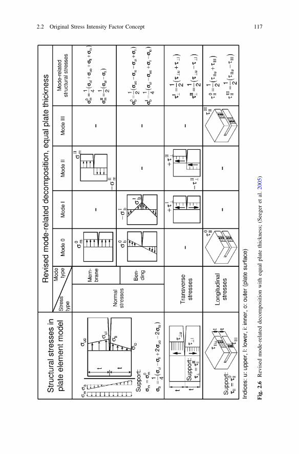
Other mode-related decompositions (mode I, mode II, mode 0 membrane andmode 0 bending) of the in-plane normal stresses are also possible. A principalstatement is elucidating in this context (Seeger et al. 2005). The four independentnormal stresses at the outer and inner plate surfaces in the cross-sectional modelcan always be substituted by or decomposed in four other independent stressescharacterising definite linearised stress groups. It is straightforward to select thefollowing mode-related stresses as such: the mode II related antimetric membranestress rII
m, the mode I related symmetric bending stress rIb and the mode 0 related
membrane and bending stresses, r0m and r0
b. Preference is given to these decom-posed stress groups, because any stress state in the cross-sectional model can thusuniquely be described by simple expressions, especially too when considering
Fig. 2.5 Self-equilibrating loading states generating a stress singularity at the slit tip; pure modeI (a), pure mode II (b) and pure mode III (c); the pairs of resultant forces are assumed to act onthe slit flanks in opposite directions in the same line each; they are evenly distributed over thespecimen width; (Radaj et al. 2006)
2.2 Original Stress Intensity Factor Concept 115

unequal plate thickness. Self-equilibrating stress groups are not a necessarycondition, because the non-equilibrated stress portions are compensated by mode 0stress distributions. Above, the pure modes I, II and III are defined by membraneand bending stresses which are not self-equilibrated in general. Mode 0 stressesand support forces are not identical as a consequence.
Another argument supports the decomposition of the shear stresses s?u; s?l,sku; sk l into symmetric and antimetric stress groups without consideration of theequilibrium conditions. The resulting decomposed stresses are identical with thosefrom a force-equilibrated decomposition also in the case of unequal plate thickness.Once more, self-equilibration is not a necessary condition.
The revised decomposition into the mode-related stresses just mentioned forjoints of equal plate thickness is presented in Fig. 2.6. The SIFs are derivedtherefrom by the following expressions:
KI ¼1ffiffiffi
3p rI
b þ 2:23sI?
� �
ffiffi
tp
ð2:33Þ
KII ¼12rII
m þ 0:55sII?
� �
ffiffi
tp
ð2:34Þ
KIII ¼ffiffiffi
2p
sIIIk
ffiffi
tp
ð2:35Þ
It should be noted that rIb ¼ rcb and rII
m ¼ rtb, which are the characteristic self-equilibrated stresses. This is an indication that self-equilibrated loading is theprimary condition of the pure loading modes.
The expression for the non-singular slit tip stresses are:
T ¼ r0m þ rI
b ¼12ðrui þ rliÞ ð2:36Þ
S ¼ s0k ¼
12ðsku þ sklÞ ð2:37Þ
The following remark may be added. The non-singular bending stress r0b
characterises a third order term in the series expansion of the stress field, whereasT-stress and S-stress are second order terms.
The original decomposition procedure for the structural stresses at the weld spotedge in joints of unequal plate thickness (Radaj and Zhang 1991(1), 1991(2)) isrelated to the self-equilibrated pure modes I, II and III. The mode 0 bendingstresses were not separated in the first version. The correspondingly amendedprocedure is visualised for the in-plane normal-stresses in Fig. 2.7.
At first, some notes are necessary on the status of the relevant publications,which present two slightly different versions of the method. The original version(Radaj and Zhang 1991(1)) does not separate the mode 0 bending stress. Thisversion has been taken over into the author’s book (Radaj et al. 2006), because thecoefficients for the KI and KII expressions are available only for this deficient
116 2 Extended Stress Intensity Factor Concepts
Fig
.2.
6R
evis
edm
ode-
rela
ted
deco
mpo
siti
onw
ith
equa
lpl
ate
thic
knes
s;(S
eege
ret
al.
2005
)
2.2 Original Stress Intensity Factor Concept 117

method (without effect on the numerical SIF results). An inconsistency in theexpressions for the decomposed edge-parallel shear stresses in the book, ibid. Eqs.(10.29) and (10.30), has to be mentioned. These stresses are not self-equilibratingfor thickness ratios d = 1.0. They should have the same form as the precedingtransverse shear expressions. The coefficients Kþ�IIIu are related to the self-equili-brating stresses (Radaj and Zhang 1991(1)).
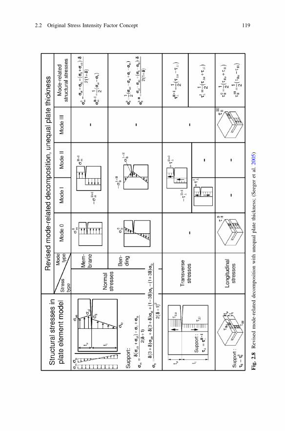
The revised decomposition into mode-related membrane and bending stressesfor joints of unequal plate thickness without the condition of self-equilibration ispresented in Fig. 2.8. The SIFs are derived therefrom by the followingexpressions:
KI ¼ ðkI;brIþIIb þ kI;mrIIþI
m þ kI;?sI? þ k�I;?s
IIþI? Þ
ffiffiffiffi
tu
pð2:38Þ
KII ¼ ðkII;brIþIIb þ kII;mrIIþI
m þ kII;?sIIþI? Þ
ffiffiffiffi
tu
pð2:39Þ
KIII ¼ kIII; ksIIIk
ffiffiffiffi
tu
pð2:40Þ
The situation above is more complicated with unequal compared with equalplate thickness. The decomposition procedure is the same in principle, but not alldecomposed stresses can be connected with a single loading mode. Some arerelated to two modes, but one of the two modes is dominant in general.
The stresses with a two-mode effect have an additional index related to thesecond mode: rI
b ! rIþIIb , rII
m ! rIIþIm , sII
? ! sIIþI? . The number of stress terms in
the expressions for KI and KII is correspondingly enlarged. The coefficients of thestress terms have an index for the mode type (I, II, III), to which they contribute,and an index for the stress type (b, m, ?; k), to which they are connected. Thesecoefficients depend on the ratio of the plate thicknesses, d = tu/tl (indices for upper
Fig. 2.7 Decomposition of the in-plane structural normal stress state at the slit tip of a lap jointcross-sectional model with unequal plate thickness into antimetrical (tension-bending) force andsymmetrical moment (counterbending) portions after separation of the non-singular membraneand bending stress portion; (Radaj and Zhang 1991(2))
118 2 Extended Stress Intensity Factor Concepts
Fig
.2.
8R
evis
edm
ode-
rela
ted
deco
mpo
siti
onw
ith
uneq
ual
plat
eth
ickn
ess;
(See
ger
etal
.20
05)
2.2 Original Stress Intensity Factor Concept 119

and lower plate). The upper plate thickness tu is the square root parameter in theSIFs.
The coefficients of the accordingly decomposed stresses in the SIF formulae arelisted in Table 2.1 for several values of d. In the line with d = 1.0, the coefficientsfrom Eqs. (2.23) and (2.24) appear. The coefficients kI,b, kI,m, kII,b, kII,m for theother values of d have been determined by application of the FE programmeFRANC2D/L. The values of kI;?; k�I;?; kII;?; kIII;k are derived from the formulaein the original publication (Radaj and Zhang 1991(1), 1991(2)). The coefficient kIII,kis found for a membrane shear stress distribution. Bending shear stresses are nottaken into account.
The coefficients of the originally decomposed stresses in the SIF formulae
(inclusive of Kres ¼ ðK2I þ K2
IIÞ1=2) are available dependent on the plate thickness
ratio d as closed form expressions and also in graphical form (Radaj and Zhang1991(1)). They are determined based on a combination of J-integral and boundaryelement method. The application to the spot-welded tensile-shear and cross tensionspecimens is also demonstrated.
Spot-welded lap joints have also been investigated with dissimilar platematerials (Radaj and Zhang 1992, 1994). Different elastic constants are assigned tothe upper and lower plate. An oscillatory stress singularity occurs at the bimaterialslit tip. It is described by special unconventional SIFs which may be substituted bythe conventional SIFs in an approximative sense for engineering applications.
Only the original mode-related version of the method, which is based on self-equilibrated stress groups, is reviewed below. A revised version based on possiblysimpler, non-equilibrated stress groups has been proposed, but not elaborated(Seeger et al. 2005). Any version has to come up with two complications. First, themode 0 membrane and bending loading states have to be based on a linear dis-tribution of the membrane and bending strains (not of the stresses), because onlythese produce no stress singularity at the slit tip. The corresponding membrane andbending stresses show a step and kink in gradient in the slit and interface plane.Second, the conventional SIFs KI and KII (not KIII) describe the stresses at the slittip only approximately. Especially, the step in the interface-parallel normal stressvalues is not reproduced, but the deviations from the exact values are not too large(Radaj and Zhang 1994).
Table 2.1 Coefficients of mode-related structural stresses for the SIFs KI, KII and KIII in joints ofunequal plate thicknesses tu (upper plate) and tl (lower plate); (Radaj and Zhang 1999; Seegeret al. 2005)
Mode I Mode II Mode III
d = tu/tl kI,b kI,m kI,\ k�I;? kII,b kII,m kII,\ kIII,k
1.0 0.578 0 2.236 0 0 0.500 0.550 1.4140.556 0.652 -0.218 2.025 0.876 -0.068 0.593 0.429 1.2470.333 0.695 -0.409 1.911 1.245 -0.130 0.700 0.325 1.1550.120 0.734 -0.671 1.794 1.656 -0.226 0.905 0.099 1.058
120 2 Extended Stress Intensity Factor Concepts

The self-equilibrated decomposition of the membrane and bending stressestaking bimaterial conditions into account is based on Fig. 2.9. The condition ofplane cross-sections is expressed by the linear distribution of the strains between eu
and el. The original plate stresses to be decomposed are ruo, rui, rli, rlo. The mode0 loading state is characterised by r�uo; r�ui; r�li; r�lo. The step in the stress valuesand in their gradient is clearly visible. Finally, the tension and counter-bendingloading states are shown which are related to the stress singularity.
The SIFs KI, KII and KIII are given by the following expressions, all coefficientsand stresses referring to the upper plate:
KI ¼ ðkI;tbrtb þ kI;cbrcb þ kþþI;? sþþ? þ kþ�I;? sþ�? Þffiffiffiffi
tup
ð2:41Þ
KII ¼ ðkII;tbrtb þ kII;cbrcb þ kþþII;?sþþ? þ kþ�II;?sþ�? Þffiffiffiffi
tu
pð2:42Þ
KIII ¼ kIII;ksþ�k
ffiffiffiffi
tup
ð2:43Þ
The coefficients kl (l = I,tb, I,cb etc.) depend on the modulus of elasticity ratioof the two materials and on the plate thickness ratio d = tu/tl. They are available asclosed form expressions for d = 1.0 (Radaj and Zhang 1992), gained by a com-bination of the boundary element and the J-integral method. The plane straincondition is appropriate when considering spot-welded joints. The linear-elasticbehaviour of isotropic materials is described by two independent elastic constants,mostly the modulus of elasticity E and Poisson’s ratio m, but sometimes also theshear modulus G. The coefficients kl are then stated dependent on the shearmodulus ratio b = Gu/Gl supplemented by Poisson’s ratios mu and ml.
Fig. 2.9 Decomposition of the in-plane structural normal stress state at the slit tip of a bimateriallap joint cross-sectional model (a), into a stress portion without singularity effect (b), and intotension-bending and counterbending portions with singularity effect (c, d); (Radaj and Zhang1992)
2.2 Original Stress Intensity Factor Concept 121

The initial step in the normal stress decomposition procedure is the separationof the mode 0 non-singular membrane and bending stresses based on the conditionof a linear strain distribution (plane cross-sections remaining plane). Rathercomplicated expressions are gained for the appertaining stresses r�uo; r�ui; r�li; r�lo(see Fig. 2.9). The characteristic stresses for mode I and mode II loading, counter-bending (index cb) and tensile-bending (index tb), are then expressed as follows:
rcb;u ¼ r�ui � rui þ 2ðr�uo � ruoÞ ð2:44Þ
rtb;u ¼ 2ðrui � r�ui þ ruo � r�uoÞ ð2:45Þ
These two equations are easily derived by considering the stresses in the upperplate after deduction of the mode 0 stresses:
rui � r�ui ¼ rtb;u þ rcb;u ð2:46Þ
ruo � r�uo ¼ �12
rtb;u � rcb;u ð2:47Þ
They are valid for any plate thickness ratio and any material combination.In the referenced publication (Radaj and Zhang 1992), ibid. Eq. (37), rtb,u is
erroneously introduced with the factor 1/2 instead of 2 in Eq. (2.45) above, but theexpressions for kI,tb and kII,tb are simultaneously changed, so that KI and KII remainunchanged. Actually, kI,tb = 0 for any modulus of elasticity ratio combined withd = 1.0 (see Fig. 6 in the referenced publication).
The decomposition of the edge-transverse and edge-parallel shear stressesbased on self-equilibrated forces can be substituted, as already stated, by adecomposition into symmetric and antimetric stress groups without causing achange in the results:
sþþ? ¼12ðs?u þ s?lÞ ð2:48Þ
sþ�? ¼12ðs?u � s?lÞ ð2:49Þ
sþ�k ¼12ðsku � sklÞ ð2:50Þ
The expression for sþ�k is derived without considering the effect of superim-
posed bending shear stresses.
2.2.9 Equivalent SIFs under Mixed Mode Loading Conditions
Mixed mode loading conditions at crack or slit tips pose the question of how theSIFs of the different modes should be superimposed to give an equivalent SIF (alsotermed ‘resultant SIF’), equivalent in respect of fatigue failure by crack initiation
122 2 Extended Stress Intensity Factor Concepts

and propagation. This includes the question of what critical value of KII or KIII isequivalent to the critical value of KI. The answer to these questions is complicatedby the fact that the crack under mixed-mode loading conditions usually propagatesin a non-coplanar manner, i.e. the crack changes its direction of propagation(‘kinked crack’). The crack propagation angle (‘kink angle’) must be found first.Additional assumptions are necessary to do this. Several hypotheses and relatedcriteria have been proposed to describe crack initiation and propagation undermixed-mode conditions. They are not generally verified by testing. It is thereforenecessary to check the applicability of the criterion selected in each individualcase.
The critical conditions for crack initiation and propagation under mixed mode Iand II conditions, specified according to different failure criteria, are plotted inFig. 2.10. The tensile KI part of the diagram is mainly taken from the literature(Sih 1975). The compressive part is supplemented as far as the criteria are definedin this region. The critical SIF ratios KI/KI,c and KII/KI,c refer to the critical SIF KI,c
in mode 1 loading: KI,c = KIc (fracture toughness) for brittle fractures, KI,c = Kth
(threshold SIF) or KI;c ¼ rE pq�=2ð Þ1=2 (endurance limit stress rE averaged overmicrostructural support length q�) for fatigue fractures. The following failurecriteria are evaluated:
Fig. 2.10 Critical stress intensities (normalised by KI,c) characterising crack propagation undermixed mode I and II loading conditions; various failure criteria; curve designations specified inthe text; (Radaj and Zhang 1995(1))
2.2 Original Stress Intensity Factor Concept 123

• The maximum tangential stress rt max at the edge of a ‘core region’ around thecrack tip (radius r�) is decisive for crack propagation (Erdogan and Sih 1963).
• The minimum strain energy density at the edge of the core region expressed bythe minimum strain energy density factor Smin is decisive for crack propagation(Sih 1973, 1974, 1975).
• The maximum dilatational strain energy density at the edge of the core regionexpressed by the corresponding factor S�max is decisive for crack propagation(Radaj and Heib 1978).
• The resultant energy release rate Gmax is decisive for coplanar crack propagation(Irwin 1957).
• The maximum energy release rate Gres is decisive for non-coplanar crackpropagation (Hussain et al. 1974).
• The process zone criteria: brittle initiation of fracture occurs at a critical value ofthe first principal stress r1b at distance r� in the direction of maximum (tensile)dilatational strain energy density; ‘ductile’ initiation of fracture occurs at acritical value of the principal shear stress s1d (or first principal stress r1d) atdistance r� in the direction of maximum (tensile) distortional strain energydensity (Radaj and Zhang 1995(1))
There are major differences in curve shape and curve position both in the tensileand the compressive range of KI which are caused by the different formal andphysical contents of the criteria. The process zone criteria differ from one anotherto a minor extent only. They are conservative compared with the conventionalcriteria. The curve for the well-known and usually preferred Erdogan–Sih criterionof maximum tangential stress, for example, runs considerably higher, especially inthe compressive KI range. The reason for this is the fact that the criterion takesonly the tangential stresses around the crack tip into account and neglects theradial stresses which are rather high under mode II conditions.
The consideration above, as far as fatigue-relevant, refers to constant-amplitudeloading of an ideal crack or slit tip with negligible mean stress effects. In realityfurther important influencing parameters have to be considered such as mean stressintensity, residual stress intensity, non-singular stresses, non-proportional loading,crack or slit tip microstructural conditions and crack closure effects among others.Whether or not a definite criterion is applicable in the special case under con-sideration should finally be decided on the basis of mixed mode fatigue testingresults. Such data are not readily available from the literature.
The preferred criterion in the case of spot-welded or seam-welded joints is themaximum tangential stress criterion. It states that the crack or slit tip subjected tomixed mode I and II loading will propagate in the direction in which the tangentialtensile stress at a small distance from the crack tip reaches its maximum. Thisresults in the crack propagation angle h as a function of the SIF ratio KII/KI,Fig. 2.11. The equivalent SIF Keq then follows from the condition of identicalvalues of rt max in mixed mode and pure mode I loading:
124 2 Extended Stress Intensity Factor Concepts

Keq ¼ KI cos2 h2� 3
2KII sin h
� �
cosh2
ð2:51Þ
tanh2¼ 1
4KI
KII
� �
� 14
ffiffiffiffiffiffiffiffiffiffiffiffiffiffiffiffiffiffiffiffiffi
KI
KII
� �2
þ8
s
ð2:52Þ
where the positive root corresponds to a negative KII, the negative root to apositive KII (with positive KI). Pure mode I loading results in h ¼ 0� and Keq = KI,whereas pure mode II loading is associated with h ¼ 70:5� and Keq = 1.15KII.
The strain energy density criterion (Sih 1973, 1974, 1975) which comprises notonly KI and KII but also KIII, is open to more varied physical interpretations andadaptable to more complex test data. The criterion states that the crack propagatesin the direction of the minimum total strain energy density at the edge of the coreregion (approximately equal to the direction of maximum dilatational strain energydensity), and that a critical value of the strain energy densities mentioned must bereached. The equivalent stress intensity factor Keq follows from:
Keq ¼ffiffiffiffiffiffiffiffiffiffiffiffiffiffiffiffiffiffiffiffiffiffiffiffiffiffiffiffiffiffiffiffiffiffiffiffiffiffiffiffiffiffiffiffiffiffiffiffiffiffiffiffiffiffiffiffiffiffiffiffiffiffiffiffiffiffiffiffiffiffiffiffi
A11K2I þ A12KIKII þ A22K2
II þ A33K2III
q
ð2:53Þ
The coefficients A11 to A33 are mainly dependent on the crack propagation angle(besides Poisson’s ratio) which in turn is defined by the stress intensity factor ratios
Fig. 2.11 Crack propagation angle h against ligament direction dependent on stress intensityfactor ratio; maximum tangential stress criterion (rt max) compared with strain energy densitycriterion (Smin); (Yuuki et al. 1985(1), 1985(2); Yuuki and Ohira 1986, 1989)
2.2 Original Stress Intensity Factor Concept 125

KII/KI and KIII/KI, respectively. The coefficients are often introduced as constant inorder to simplify the procedure. The following simplified version of Eq. (2.53)follows from the application of the strain energy density criterion to the single-mode loading states of a centre crack in the infinite plate. With Poisson’s ratiom = 0.28, the ratios of critical SIFs are KII,c/KI,c = 0.985 and KIII,c/KI,c = 0.663,thus yielding the following formula, (Sih 1973), ibid. Eqs. (16) and (18):
Keq ¼ffiffiffiffiffiffiffiffiffiffiffiffiffiffiffiffiffiffiffiffiffiffiffiffiffiffiffiffiffiffiffiffiffiffiffiffiffiffiffiffiffiffiffiffiffiffiffi
K2I þ 1:03K2
II þ 2:27K3III
q
ð2:54Þ
A similar equation is obtained proceeding from the resultant energy release ratecriterion (Irwin 1957) which assumes coplanar crack propagation and ignores theinfluence of the crack propagation angle:
Keq ¼ffiffiffiffiffiffiffiffiffiffiffiffiffiffiffiffiffiffiffiffiffiffiffiffiffiffiffiffiffiffiffiffiffiffiffiffiffiffiffi
K2I þ K2
II þ 1:39K2III
q
ð2:55Þ
Here, m = 0.28 is introduced, resulting in 1/(1 - m) = 1.39. The sameexpression is derived based on the J-integral. This relationship has occasionallybeen applied to spot-welded lap joints (Linder et al. 1998).
The process zone criteria (Radaj and Zhang 1995(1)) also yield the general formof Eq. (2.53) partly extended by the addition of linear KI and KII terms. Thecorresponding curves in Fig. 2.10 (r1d and s1d for ‘ductile’ behaviour, r1b forbrittle behaviour) result from evaluating the crack propagation angle in the dif-ferent mixed-mode (inclusive of single-mode) loading states. The following moreconservative form, Eq. (2.56), is proposed on the basis of the lower plotted curvesin Fig. 2.10 substituting the older, less conservative form, Eq. (2.57), chosen inseveral comparative evaluations related to spot-welded joints (Radaj et al. 1990,2006; Radaj and Giering 1994, 1995; Radaj and Zhang 1995(2)):
Keq ¼ffiffiffiffiffiffiffiffiffiffiffiffiffiffiffiffiffiffiffiffiffiffiffiffiffiffiffiffiffiffiffiffi
K2I þ 3K2
II þ K2III
q
ð2:56Þ
Keq ¼ffiffiffiffiffiffiffiffiffiffiffiffiffiffiffiffiffiffiffiffiffiffiffiffiffiffiffiffiffiffi
K2I þ K2
II þ K2III
q
ð2:57Þ
Kurath has found that K2II combined with the factor 3 is valid in the case of spot
welds of low-carbon steels and combined with the factor 2 in the case of spotwelds of high-strength steels (Kurath 1992). The factor 4.3 has been derived fromfatigue test results gained from single-spot specimens with various ratios KI/KII
(Lee and Kim 2004).Similar formulae have been derived based on the assumption of coplanar crack
propagation described by a critical averaged stress over the microstructural lengthq� (Neuber’s hypothesis). Different failure criteria (Rankine’s normal stress, vonMises’ distortional strain energy, Beltrami’s total strain energy) are combined withplane stress or plane strain multiaxiality conditions, see Sect. 1.5.2.
A diagram derived for kinked crack propagation under mixed-mode loadingconditions of the crack in non-welded steels (Pook 1989) is presented in Fig. 2.12.
126 2 Extended Stress Intensity Factor Concepts

The reference quantity DK�0 is the cyclic threshold stress intensity factor for kinkedor branched macro-crack propagation which may be about twice the thresholdvalue for coplanar crack propagation in mode I.
The equivalent stress intensity factors according to Eqs. (2.51–2.57), whenapplied to cyclic loading, do not include the further influencing parameters gov-erning fatigue, e.g. prestress or crack closure. Another shortcoming is the absenceof the non-singular stress terms whose influence on fatigue crack initiation andpropagation may be important (Haefele and Lee 1995).
2.2.10 Endurable Stress Intensity Factors
Endurable SIFs were originally defined in respect of static loading consideringbrittle fracture as limit condition. The fracture toughness KIc obtained in mode 1fracture tests is the relevant material parameter. To ensure a sufficiently brittlespecimen behaviour is an essential requirement on the testing procedure. Size andthickness of the specimen must be kept sufficiently large in order to maintain apredominantly elastic behaviour with three-dimensional tensile stresses ahead ofthe crack tip and with plastic deformations at the crack tip more or less avoided.
Endurable SIFs defined in respect of fatigue loading are the threshold SIFsDKth, which are considered as material parameters. The parameter DKth denotesthe minimum cyclic stress range at which propagation of a (sufficiently long) crackis observed. In general, mode I testing in the high-cycle fatigue range is performedfor this purpose. A typical lower bound value for structural steels isDKth = 180 MPa mm1/2 (valid for R = 0).
Fig. 2.12 Lower limit curvesof the cyclic threshold stressintensity factors for kinked orbranched macrocrackpropagation under mixedmode loading conditions(modes I, II and IIIsuperimposed), based on testresults for various steels;(Pook 1989)
2.2 Original Stress Intensity Factor Concept 127
The existence of a threshold value is explained by crack closure phenomenaoccurring in cyclic loading (Elber 1970, 1971). Under plane stress conditions,crack closure originating from plastic deformation at the crack tip is the pre-dominant effect. Under plane strain conditions, other phenomena are prevailing:surface roughness, fracture particles and oxide formation.
A rough estimate of DKth can also be gained on the basis of Neuber’s micro-structural support hypothesis, using the available data for structural steels (endurancelimit for averaged stresses in polished surface, DrE ¼ 270 MPa, microstructural
length, q� = 0.1 mm) the result is DKth ¼ DrEðpq�=2Þ1=2 ¼ 107 MPa mm1=2:The use of endurable SIFs DK for the fatigue assessment of spot-welded joints
is well established. Several investigations have been performed with tensile-shearloaded and peel-tension loaded specimens made of low-alloy steels, high-strengthsteels among them. The test results are plotted in the form of K–N curves (enduredcycles N for different SIFs DK, interpreted as endurable SIFs DK over cycles N).These investigations and their results have been reviewed and compared (Radajet al. 2006, ibid. pp. 471–476). The scatter of the K–N curve of a definite specimentype under investigation is generally small, but the deviations between the resultsof different authors are large and often unexplained.
Most influential on these deviations is a deficient determination of the SIFs inthe spot-weld specimen under consideration. Factors 0.2–3.0 occur in the literaturecompared with the correct values. Thus, the corresponding K–N curves are by thesame factors too low or too high. In the following, only one typical K–N curve forspot-welded joints (Yuuki et al. 1985(1), 1985(2); Yuuki and Ohira 1986, 1989) isfurther discussed. The SIF DKeq is plotted over number of cycles N in logarithmicscales, Fig. 2.13, representing the K–N curve in the following form:
N ¼ AkðDKeqÞ�k ð2:58Þ
with the inverse slope exponent k and the coefficient Ak assumed to be materialparameters. Similar investigations with comparable results can be found in theliterature (Mizui et al. 1988; Linder et al. 1998).
The SIF DKeq is determined according to the maximum tangential stresscriterion. The inverse slope exponent results as k = 4.5. The calculated SIFs areby a factor of 0.7–0.8 too low. Taking this factor into account, the endurable SIFsfor N C 5 9 106 cycles roughly agree with the generally accepted lower boundvalue for non-welded structural steels, DKth = 180 MPa mm1/2.
The width of the scatter band of the K–N curve is well in agreement with otherlocal parameter curves which are used for fatigue assessment. Attributing thefailure probabilities Pf = 2.3 and 97.7 % to the limiting curves in the figure, thefollowing scatter range indices are derived:
TN ¼ N2:3=N97:7 ¼ 0:1; Tr ¼ ðTNÞ1=k ¼ 0:6 ð2:59Þ
128 2 Extended Stress Intensity Factor Concepts

Several deficiencies besides too low SIFs in the investigation leading toFig. 2.13 have to be noted: no thickness adaption of DKeq, the non-singular orT-stress neglected, the total life evaluated instead of the crack initiation life.
2.2.11 Conclusions
The definition and use of SIFs for describing the stress field at crack tips or pointedslit tips and their application to fatigue and brittle fracture phenomena is a wellestablished procedure for more than 50 years. Both the theoretical concepts andthe application-relevant details are generally known. In this section, the SIFconcept has been reviewed, giving the basic stress field equations for areas close tothe crack tip or slit tip, separated in singular and non-singular parts, the singularpart subdivided into the three loading modes, the non-singular part consisting of
Fig. 2.13 Endurable stress intensity factor range at the weld spot of various specimens underdifferent loading conditions according to maximum tangential stress criterion; inverse slopeexponent k = 4.5; (Yuuki et al. 1985(1), 1985(2); Yuuki and Ohira 1986, 1989)
2.2 Original Stress Intensity Factor Concept 129

T-stress, S-stress and a crack-front-parallel normal stress. Coupled singular effectsmay additionally occur where the crack front butts on a free surface.
The presented stress field equations and their governing parameters (SIFs KI,KII and KIII, T-stress, S-stress) are made available for seam-welded and spot-welded lap joints based on a structural stress analysis which avoids modelling ofthe singular stresses. Lap joints with equal and unequal plate thickness, respec-tively, are considered.
Mixed mode loading conditions are taken into account by equivalent SIF for-mulae representing various fracture criteria. Endurable SIFs for spot-welded jointsare given in the form of a K–N curve with defined scatter range. These data areunreliable because the underlying SIF analysis results may be rather inaccurate.There is an urgent demand for a better substantiated and more accurate designK–N curve. Only relative fatigue assessments are possible based on accurate SIFanalyses without a reliable K–N curve.
2.3 Notch Stress Intensity Factor Concept
2.3.1 Survey of Section Contents
The stress intensity factor (SIF) concept referring to crack tips or slit tips isextended to V-notch tips or re-entrant corner tips in the form of the notch stressintensity factor (NSIF) concept. The stress singularities associated with suchpointed notches are less marked and expressed by a smaller negative exponent ofthe radial distance from the notch tip. The stress field equations for the area closeto the notch tip are given for the three singular loading modes 1, 2 and 3 and forthe non-singular mode characterised by the S-stress. A transverse singular effectcoupled with mode 2 loading at free surfaces is identified and described.
The NSIF concept is applied to the re-entrant corner notches at the toe of filletwelds and butt welds. The size effect is naturally included. A link betweenstructural stress and NSIF is established. Equivalent NSIF formulae are presented,referring to failure under mixed mode loading conditions. Endurable NSIFsdependent on number of load cycles N are given for non-load-carrying fillet weldsof attachment joints. In parallel, the J-integral concept for pointed V-notches ispresented and applied.
The expositions are primarily based on the pioneering analytical developmentsand their practical applications (mainly to welded joints) carried out by Atzori,Lazzarin, Tovo, Livieri, Meneghetti and others. A list of symbols and a list ofreferences is available at the end of Chap. 2
130 2 Extended Stress Intensity Factor Concepts

2.3.2 Stress Field near Pointed V-Notches
The well-known concept of stress intensity factors describing the stress singularityat crack tips or slit tips under elastic material conditions can be transferred topointed re-entrant corner notches (e.g. V-notches, stepped bars, weld toe notches).Whereas the asymptotic stress drop from the singularity at the crack tip isdescribed by the inverse square root of the radial distance r from the crack tip (theexponent is minus 0.5), a smaller, notch angle dependent exponent occurs in thecase of corner notches, which means that the degree of the singularity is reduced(Williams 1952). The stress field close to corner notches (just as the stress fieldclose to crack tips) can be described by stress intensity factors (Gross and Men-delson 1972). These are named ‘notch stress intensity factors’ (NSIFs) as distin-guished from the conventional stress intensity factors (SIFs) of crack tips.
The singular in-plane and out-of-plane stress fields at pointed corner notchescan be specified by three notch loading modes (in analogy to the crack openingmodes) related to the bisector plane of the notch: symmetric in-plane stresses(mode 1), antimetric in-plane stresses (mode 2) and out-of-plane shear stresses(mode 3). The corresponding notch loading modes are in-plane tensile loading, in-plane shear loading and out-of-plane shear loading.
The three basic loading modes with singular stresses at the notch tip producethe following asymptotic stress distribution (stress tensor rij) around the notch tip,restricted to the first order terms (Williams 1952; Hasebe et al. 1990; Lazzarin andTovo 1996, 1998; Quian and Hasebe 1997), Fig. 2.14:
rij ¼1ffiffiffiffiffiffi
2pp K1rk1�1f1; ijðhÞ þ K2rk2�1f2; ijðhÞ þ K3rk3�1f3; kzðhÞ
� �
ði, j ¼ x; y and k ¼ x; y or i, j ¼ r; h and k ¼ r; hÞð2:60Þ
Fig. 2.14 Cartesian (a) and polar (b) coordinate systems with correspondingly defined stresses atthe pointed V-notch tip; (Lazzarin and Tovo 1998)
2.3 Notch Stress Intensity Factor Concept 131

The NSIFs K1, K2, K3 depend on the magnitude of the load, the notch depth a,the notch opening angle 2a and further geometric parameters of the consideredconfiguration. The angular functions f1,ij, f2,ij, f3,kz describe the angular distributionof the stress close to the notch tip. The relationship above is strictly valid for r ! 0and approximately valid for values of r which are small in relation to the notchdepth and other geometrical parameters of the configuration.
Just as with the crack problem (2a = 0), the complete solution comprises non-singular higher order terms, but only a finite number for rather small values of 2aand no such terms for about 2a[ 45� (Atzori et al. 1997, ibid. Fig. 3).
The original solution for the in-plane stress field is based on the Airy stressfunction in polar coordinates in the following form, which comprises a symmet-rical and an antimetrical component (Williams 1952; Sanford 2003):
Fðr; hÞ ¼ rkþ1f ðhÞ ð2:61Þ
where the values of k have to be determined as part of the solution. The angularfunctions have to comply with the boundary conditions on the load-free faces ofthe V-notch (actually Williams started with the wedge, extending the solution toV-notches by considering inscribed wedge angles larger than p).
The stress can now be expressed in terms of r, k and f(h). Application of theboundary conditions produces a system of four simultaneous equations for fourunknown constants. This system can be separated into two independent sets ofequations related to the symmetrical and antimetrical stress fields. A non-trivialsolution can be obtained only if the determinants of the coefficient matrices areequal to zero each. From this requirement, the condition follows:
sin 2ka ¼ �k sin 2a ð2:62Þ
Since 2a is a fixed parameter for a specific wedge or notch, Eq. (2.62) providesthe values of k, called ‘eigenvalues’, necessary to ensure a nontrivial solution.Williams’ solution has been widely used under the name ‘eigenfunction expansionmethod’ (Hasebe et al. 1990).
Another function-analytical approach for solving the problem of the in-planeloaded blunt V-notch comprising the pointed V-notch has been applied by Lazz-arin et al. while the principal mathematical steps remained the same as in the Airystress function method (Lazzarin and Tovo 1996, 1998; Lazzarin et al. 1998;Atzori et al. 1997). According to the Kolosov–Muskhelishvili complex stressfunction method, the stress fields at symmetrical V-notches subjected to mode 1and mode 2 loading can be derived from two analytical functions defined in thefollowing form:
uðzÞ ¼ azk; wðzÞ ¼ bzk þ czl ð2:63Þ
where the coefficients a, b, c are complex and the exponents k, l real (k[ l).Williams’ results would be gained with the term czl being neglected.
132 2 Extended Stress Intensity Factor Concepts

In order to impose the boundary conditions, an auxiliary system of curvilinearcoordinates w = u ? iv is introduced (Neuber 1958), which is related to theCartesian coordinates z = x ? iy by the conformal mapping function
z ¼ wq ð2:64Þ
The condition u = 0 describes the pointed V-notch with notch opening angle 2ain the z-plane:
2a ¼ 2p� qp; q ¼ 2p� 2ap
ð2:65Þ
where q = 2.0-1.0 for 2a = 0-2p.The eigenvalues in the considered method and application result from the
following condition, separated into the mode 1 and mode 2 parts:
sin k1qpþ k1 sin qp ¼ 0 ð2:66Þ
sin k2qp� k2 sin qp ¼ 0 ð2:67Þ
The stress field analysis for the V-notch subjected to out-of-plane shear loading(mode 3) is easier to perform, because the governing equation in terms of the out-of-plane displacements is a potential function substituting the bipotential functionin the case of the in-plane stresses. Performing similar mathematical steps asbefore, the following eigenvalue equation is found (Quian and Hasebe 1997):
sin k3ð2p� 2aÞ ¼ 0 ð2:68Þ
The first non-zero eigenvalue is simply:
k3 ¼p
2p� 2að2:69Þ
Actually, Quian and Hasebe have solved the more complex case of anunsymmetrical V-notch with a bimaterial interface ahead of the notch root, butwith restriction to pointed notches.
The (first) eigenvalues k1, k2, k3 defining the degree of the stress singularity atthe notch tip depend solely on the notch opening angle 2a (Williams 1952; Car-penter 1984), Fig. 2.15. The eigenvalue 0.5 is related to crack tips, 2a = 0, and theeigenvalue 1.0 (no singularity) to straight edges, 2a = p (but only for mode 1 andmode 3). The eigenvalues for mode 1 loading are slightly smaller than those formode 3 loading. They are substantially smaller in relation to mode 2 loading, thusdesignating severer singularities. The stress singularity in mode 2 loading isweaker and vanishes completely for 2a C 102.6�.
The in-plane stresses at the pointed V-notch (q = 0) are derived in the fol-lowing form after introduction of the NSIFs K1 and K2 proposed by Gross andMendelson (Lazzarin et al. 1998):
2.3 Notch Stress Intensity Factor Concept 133

rh
rr
srh
8
>
<
>
:
9
>
=
>
;
1
¼ 1ffiffiffiffiffiffi
2pp rk1�1K1
ð1þ k1Þ þ v1ð1� k1Þ
�ð1þ k1Þ cosð1� k1Þhð3� k1Þ cosð1� k1Þhð1� k1Þ sinð1� k1Þh
8
>
<
>
:
9
>
=
>
;
þ v1ð1� k1Þcosð1þ k1Þh� cosð1þ k1Þh
sinð1þ k1Þh
8
>
<
>
:
9
>
=
>
;
2
6
4
3
7
5
rz;1 ¼ mðrh;1 þ rr;1Þ ðplane strainÞ
v1 ¼ �sinð1� k1Þqp=2sinð1þ k1Þqp=2
ð2:70Þ
rh
rr
srh
8
>
<
>
:
9
>
=
>
;
2
¼ 1ffiffiffiffiffiffi
2pp rk2�1K2
ð1þ k2Þ þ v2ð1� k2Þ
��ð1þ k2Þ cosð1� k2Þh�ð3� k2Þ cosð1� k2Þhð1� k2Þ sinð1� k2Þh
8
>
<
>
:
9
>
=
>
;
þ v2ð1� k2Þ� sinð1þ k2Þhsinð1þ k2Þhcosð1þ k2Þh
8
>
<
>
:
9
>
=
>
;
2
6
4
3
7
5
rz;2 ¼ mðrh;2 þ rr;2Þ ðplane strainÞ
v2 ¼ �sinð1� k2Þqp=2sinð1þ k2Þqp=2
ð2:71Þ
The antimetrical singular and symmetrical non-singular out-of-plane shearstresses have the following form (Zappalorto and Lazzarin 2011(3)) correspondingto Eq. (2.126):
Fig. 2.15 Eigenvalues k1,k2, k3 defining the degree ofstress singularity at pointedV-notches subjected to mode1, 2, 3 loading conditions,dependent on notch openingangle 2a; (Lazzarin et al.2004)
134 2 Extended Stress Intensity Factor Concepts
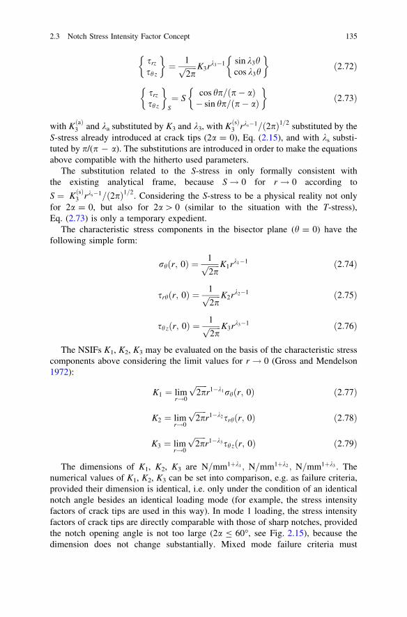
srz
sh z
� �
¼ 1ffiffiffiffiffiffi
2pp K3rk3�1 sin k3h
cos k3h
� �
ð2:72Þ
srz
sh z
� �
S
¼ Scos hp=ðp� aÞ� sin hp=ðp� aÞ
� �
ð2:73Þ
with KðaÞ3 and ka substituted by K3 and k3, with KðsÞ3 rks�1=ð2pÞ1=2 substituted by theS-stress already introduced at crack tips (2a = 0), Eq. (2.15), and with ks substi-tuted by p/(p - a). The substitutions are introduced in order to make the equationsabove compatible with the hitherto used parameters.
The substitution related to the S-stress in only formally consistent withthe existing analytical frame, because S! 0 for r ! 0 according to
S ¼ KðsÞ3 rks�1=ð2pÞ1=2. Considering the S-stress to be a physical reality not onlyfor 2a = 0, but also for 2a[ 0 (similar to the situation with the T-stress),Eq. (2.73) is only a temporary expedient.
The characteristic stress components in the bisector plane (h = 0) have thefollowing simple form:
rhðr; 0Þ ¼ 1ffiffiffiffiffiffi
2pp K1rk1�1 ð2:74Þ
srhðr; 0Þ ¼ 1ffiffiffiffiffiffi
2pp K2rk2�1 ð2:75Þ
sh zðr; 0Þ ¼ 1ffiffiffiffiffiffi
2pp K3rk3�1 ð2:76Þ
The NSIFs K1, K2, K3 may be evaluated on the basis of the characteristic stresscomponents above considering the limit values for r ! 0 (Gross and Mendelson1972):
K1 ¼ limr!0
ffiffiffiffiffiffi
2pp
r1�k1rhðr; 0Þ ð2:77Þ
K2 ¼ limr!0
ffiffiffiffiffiffi
2pp
r1�k2srhðr; 0Þ ð2:78Þ
K3 ¼ limr!0
ffiffiffiffiffiffi
2pp
r1�k3sh zðr; 0Þ ð2:79Þ
The dimensions of K1, K2, K3 are N=mm1þk1 ; N=mm1þk2 ; N=mm1þk3 . Thenumerical values of K1, K2, K3 can be set into comparison, e.g. as failure criteria,provided their dimension is identical, i.e. only under the condition of an identicalnotch angle besides an identical loading mode (for example, the stress intensityfactors of crack tips are used in this way). In mode 1 loading, the stress intensityfactors of crack tips are directly comparable with those of sharp notches, providedthe notch opening angle is not too large (2a B 60�, see Fig. 2.15), because thedimension does not change substantially. Mixed mode failure criteria must
2.3 Notch Stress Intensity Factor Concept 135

therefore be based on self-normalised NSIFs (Sect. 2.3.6). Failure criteria based onaveraged notch stresses (Chap. 1) or on averaged strain energy density (Chap. 3)are appropriate in other cases.
2.3.3 Transverse Singular Effect at In-Plane Shear-LoadedV-Notches
The elementary singularities in the loading modes 1, 2 and 3 may be locallycoupled in three-dimensional configurations. One typical example is the crackfront in a plate of finite thickness subjected to in-plane shear loading (mode 2),Fig. 2.16.
The exaggerated deformation plot of the crack tip region subjected to mode 2loading shown in the figure illustrates the transverse expansion of the compressiveloaded plate side and the transverse contraction of the tensile loaded plate side. Atthe crack front, the two opposed deformations lock each other. This produces out-of-plane shear stresses of opposite direction above and below the midplane. Theyvanish in the midplane and on the two plate surfaces and have a maximum closelyunderneath the surfaces. They constitute an out-of-plane (‘transverse’) shear stresssingularity which resembles a mode 3 singularity, but remains symmetrical rela-tive to the midplane. Its intensity is significantly affected by the Poisson’s ratio m.The singularity effect is largest for m = 0.5 and zero for m = 0. Simultaneously, themode 2 intensity varies through the plate thickness, assuming Williams’ originalvalue only at a distance from the crack front of about half the plate thickness.Similar effects can be expected for non-zero notch opening angles.
The literature on coupled three-dimensional singular effects is shortly reviewed.Benthem studied these effects associated with the intersection of a wedge front offinite length with the free surface of the half space (Benthem 1977). Nakamura andParks investigated the in-plane shear-loaded crack front intersecting a free surfaceas described above (Nakamura and Parks 1989). Kotousov analysed the tensileloaded V-notch in three dimensions (Kotousov and Wang 2002; Kotousov 2005;
Fig. 2.16 Enlargeddeformation of a mode IIloaded plate specimen with acrack showing a transversesingular loading effect closelyunderneath the surfaces at thecrack tip; (Harding et al.2010)
136 2 Extended Stress Intensity Factor Concepts

Kotousov and Lew 2006). The following presentation refers to in-plane shear-loaded V-notches (Harding et al. 2010; Berto et al. 2011).
For describing the transverse singular effect at in-plane shear-loaded V-notches(with inclusion of cracks), the Kane and Mindlin assumptions for a flat plate ofthickness 2h are adopted in the following form (Kane and Mindlin 1956):
ux ¼ uxðx; yÞ; uy ¼ uyðx; yÞ; uz ¼z
hw ðx; yÞ ð2:80Þ
The following two governing equations of a corresponding first order platetheory may be derived (Yang and Freund 1985):
r4w� j2r2w ¼ 0 ð2:81Þ
r6U� j2r4U ¼ 0 ð2:82Þ
j2 ¼ 6h2ð1� mÞ ð2:83Þ
where U is the stress resultant function and j a stiffness parameter.A further harmonic displacement function w is introduced for describing the in-
plane and out-of-plane displacements. Assuming a general asymptotic behaviourof w, U and w at the notch tip and adopting the eigenfunction expansion method,the following eigenvalue equation is derived (Kotousov 2007; Harding et al.2010):
sin 2k2ðp� aÞ � k2 sin 2ðp� aÞ½ � cos kOðp� aÞ ¼ 0 ð2:84Þ
The expression in brackets set to zero corresponds to Williams’ in-plane shearstress solution, Eq. (2.62). The term cos kO(p - a) set to zero describes an out-of-plane shear loading mode, Eq. (2.68). It has been shown that 0 \ k2 \ 1.0 (sin-gularity) occurs for 0 \ 2a\ 102.6� whereas k2 [ 1.0 (no singularity) results for102.6� \ 2a\ 180�. On the other hand, 0 \ kO \ 1.0 is found for 0 \ 2a\ 180�.The eigenvalues kO and k3 are identical because the eigenvalue equations can bepresented in the same form. The expression for kO = k3 is given by Eq. (2.69).
However, there are major differences between mode O and mode 3. The out-of-plane singular mode O is a local mode coupled to the applied mode 2 due to aPoisson’s ratio effect producing a symmetric shear stress distribution relative to themidplane of the plate. In contrast, the out-of-plane singular mode 3 is an inde-pendent loading mode associated with an antimetric shear stress distribution rel-ative to the midplane that is totally independent of Poisson’s ratio (Harding et al.2010).
A numerical investigation using the FE method has been performed in order tostudy the dependence of the out-of-plane singular mode on notch opening angleand Poisson’s ratio. The region near to the notch tip (radial distance r B 5h, withplate thickness 2h) is discretised into a fine mesh of higher-order three-dimen-sional elements (15-node wedge-shaped and 20-node trapezoidal). The NSIFs are
2.3 Notch Stress Intensity Factor Concept 137

found by the following limit values applied to the numerical data in the closeneighbourhood of the notch tip (Seweryn and Zwolinski 1993):
K2 ¼ limr!0ð2prÞ1�k2srh ð2:85Þ
KO ¼ limr!0ð2prÞ1�kOsh z ð2:86Þ
In the vicinity of the notch tip, the stress state is essentially three-dimensional. Itcomprises the singular out-of-plane loading mode O as well as the variability of theNSIF K2 in the plate thickness direction. As a reference value, the nominal NSIF K2,n
is introduced which corresponds to Williams’ two-dimensional stress field solution.Typical results of the investigation are shown in Fig. 2.17 where the NSIF ratio
KO/K2,n is plotted over the midplane distance z/h for three Poisson’s ratios m. The out-of-plane NSIF KO is continuously rising to a maximum closely underneath the freesurfaces of the plate. The rise is steeper for small notch opening angles. The largestvalues of KO occur for m = 0.5, and KO vanishes for m = 0. The NSIF K2 is also muchlarger close to the free surface in comparison to its midplane value. Since the degreeof the mode O singularity is greater than that of the mode 2 singularity (for 2a = 0),the effect of transverse mode O loading increases with the plate thickness.
The transverse singular effect in mode 2 loading is of relevance for application.Some interesting results are presented by Lazzarin and Berto (Harding et al. 2010;Berto et al. 2011). The welded lap joint models investigated using the FE methodare shown in Fig. 2.18. The transverse singular effect is initiated at the stress-freelateral surface of the three-dimensional models and decreases in the direction ofthe midplane.
Based on the strain energy density approach, it is shown that the critical area infatigue loading of slits (2a = 0) is at the lateral surfaces for plate thicknessesgreater than approximately 10 mm. It is shifted to the midplane for smallerthicknesses. The effect would be more pronounced if the ligament width were
Fig. 2.17 NSIF ratio KO/K2,n dependent on midplane distance z/h; out-of-plane singular mode Ocoupled with in-plane singular mode 2; plate thickness 2h, Poisson’s ratio m and nominal NSIFK2,n; (Harding et al. 2010)
138 2 Extended Stress Intensity Factor Concepts

reduced relative to the plate thickness, resulting in an increase of mode 2 relativeto mode 1 loading.
It is shown for notch opening angles 2a C 102.6�, where the in-plane shearstress singularity disappears, that the associated out-of-plane shear stress singu-larity still exists and may be dominant in the failure initiation phase.
Fig. 2.18 Welded lap joint models subjected to tensile-shear loading: two-dimensional modelwith slit opening angle 2a = 0� (a) and corresponding three-dimensional model (b); two-dimensional model with notch opening angle 2a = 135� (c) and corresponding three-dimensionalmodel (d); (Harding et al. 2010)
2.3 Notch Stress Intensity Factor Concept 139
2.3.4 NSIF Values of V-Notches and Weld Toe Notches
The NSIF values of V-notches and weld toe notches have been determined by a majornumber of authors. The weld toe notches are treated as a special case of V-notches(2a & 135�) mainly by Italian researchers (Atzori et al. 1999(2); Lazzarin et al.1998). Different methods are involved. The most general and convenient method isthe eigenvalue expansion of the notch stress field according to Williams (also named‘asymptotic solution’), mostly combined with conventional FE analysis.
Asymptotic stress distributions at weld toe notches have been derived as earlyas 1985/86 without defining the NSIF parameter and without separating the mode1 and mode 2 contributions (Atzori 1985; Lazzarin 1986). The clear analyticalframe was established 1998 by Lazzarin and Tovo in the publication referencedabove.
Various other methods have been used. Originally, the boundary collocationmethod was preferred (Gross and Mendelson 1972). Later on, special notch tipfinite elements have been designed which incorporate the stress singularity: hybridfinite elements (Lin and Tong 1980), degenerate asymptotic finite elements (Akin1976) and finite elements with constraints (Seweryn 2002). Three approaches areavailable for evaluating the NSIFs: direct evaluation at the singularity point,asymptotic evaluation outside the singularity point (comparison of numerical andanalytical solutions) and energy methods (J-integral and strain energy densityaveraged over a control volume). The boundary element method is applicable withor without special singularity elements. Singular integral equations have also beensuccessfully used (Theocaris and Ioakimidis 1979; Noda et al. 1996; Noda andTakase 2003; Savruk and Kazberuk 2006, 2007, 2010).
Useful NSIF data can be found in several publications (Gross and Mendelson1972; Chen 1995; Seweryn and Molski 1996; Dunn et al. 1997(1), 1997(2);Lazzarin et al. 1998; Atzori et al. 1999(1); Noda and Takase 2003; Savruk andKazberuk 2010). An extensive parametric investigation has been performed on theNSIFs at torsional loaded round bars with a circumferential hyperbolic notch ofdifferent notch opening angles 2a and different ratios of notch depth a to net cross-section radius R (Zappalorto et al. 2009). The closed form solution for the deephyperbolic notch is combined with FE analysis results for notches of finite depth.The evaluated dimensionless NSIF is k3 ¼ K3=s�nR1�k3 :
The main area of application of the NSIFs are fillet-welded joints showing anydegree of penetration, but also butt-welded joints with the typical weld rein-forcement are analysed in this way. The weld toe may be considered as a re-entrantcorner notch of opening angle 2a = 135� resulting in a bisector plane inclinationof 112.5� against the plate surface. The stress field at the weld toe may then bedescribed by the NSIFs K1, K2 and K3, possibly supplemented by non-singularstress components (the out-of-plane S-stress and a superimposed normal stress inthe direction of the toe line). Based on the NSIFs, fatigue test data may be eval-uated in a form which includes the size effect. Geometries scaled in geometricalproportion and subjected to the same nominal stress are characterised by different
140 2 Extended Stress Intensity Factor Concepts
NSIF values. The NSIFs are used independent of whether the weld notch is reallypointed or only sharply rounded. Only excessively large toe notch radii (shape-optimised welds) must be excluded. The assumption of pointed toe notches cor-responds to the worst-case procedure in the fatigue assessment codes.
Considering a cross-section of finite width ahead of the notch, this width may beset equal to the plate thickness t of fillet-welded joints, the NSIFs can be expressedin the following form (Lazzarin et al. 1998):
K1 ¼ k1rnt1�k1 ð2:87Þ
K2 ¼ k2rnt1�k2 ð2:88Þ
K3 ¼ k3s�nt1�k3 ð2:89Þ
where rn and s�n are the nominal stresses over the plate thickness t and k1, k2, k3 arethe geometry coefficients quantified further below. With regard to the applicationto fillet-welded joints, the reference stress of K2 in Eq. (2.88) is not the nominalshear stress sn but the nominal tensile stress rn.
The NSIFs for fillet-welded joints (notch opening angle 2a = 135�) have thefollowing form:
K1 ¼ k1rnt0:326 ð2:90Þ
K2 ¼ k2rnt�0:302 ð2:91Þ
K3 ¼ k3s�nt0:200 ð2:92Þ
The negative exponent of t in the expression for K2, Eq. (2.91), designates non-singular stresses at the pointed notch. These can be neglected in strength predic-tions in comparison to the singular stresses described by K1 and K3, but they haveto be taken into account when evaluating the stresses in front of the weld toe, Eq.(2.95), where strain gauges may be applied.
The Eqs. (2.87–2.89) are well suited to catch the size effect on the static orfatigue strength of corner-notched members, fillet-welded joints among them,provided the strength can be characterised by the NSIF (identical notch openingangles are a precondition). The following relationship is derived from Eq. (2.87)for the ratio of endurable nominal stresses rn1 and rn2 acting on the plate thick-nesses t1 and t2:
rn2
rn1¼ k11
k12
t1
t2
� �1�k1
ð2:93Þ
where k11 and k12 are the geometry coefficients k1 of the members 1 and 2.In cases of a large net cross-sectional width between the notch tips, the notch
depth a is the governing parameter instead of the plate thickness t, leading to thefollowing relationship (Dunn et al. 1997(1), 1997(2)):
2.3 Notch Stress Intensity Factor Concept 141

rn2
rn1¼ Y1
Y2
a1
a2
� �1�k1
ð2:94Þ
where Y1 and Y2 are the geometry coefficients of the members 1 and 2.The dimensionless geometry coefficients k1, k2, k3 in Eqs. (2.87–2.89) are
determined based on extremely fine-meshed cross-sectional FE models of theconsidered welded joints evaluating the stresses in the bisector plane where theyare decoupled for the three loading modes. Any stress value along the bisectorplane, but sufficiently close to the notch tip, can be used to determine the NSIF byapplying Eqs. (2.77), (2.78) or (2.79) and therefrom the geometry coefficient byevaluating Eqs. (2.90), (2.91) or (2.92). Systematic numerical investigationsrelated to fillet-welded joints have been conducted (Lazzarin et al. 1998; Tovo andLazzarin 1999).
A first investigation was related to plane models of weld-like outer geometrieswithout the inner slits, Fig. 2.19. The geometry coefficients k1 and k2 dependent onthe geometrical parameters (dimension ratios) are shown in Fig. 2.20. Thenumerical results are approximated by polynomials applying the least squaremethod. The coefficient k1 rises with L/t and 2h/t, the coefficient k2 does theopposite. Plastic notch stress intensity factors with appertaining stress distributionshave also been determined for the considered joint-similar models (Lazzarin et al.2001).
Fig. 2.19 Plane models with weld-like outer geometries (i.e. without the inner slits) subjected totensile loading, investigated numerically using the FE method; (Lazzarin et al. 1998)
142 2 Extended Stress Intensity Factor Concepts

A second investigation was related to more realistic cross-sectional models offillet-welded joints (through-welded cruciform joint, cover plate joint, top-cutcruciform joint) subjected to tensile loading, Fig. 2.21. Parametrical variationswere considered for the cruciform attachment joint with non-load-carrying filletwelds resulting in the values of k1 and k2 plotted in Fig. 2.22. The curve shapes aresimilar to those referring to the weld-like plane models (Fig. 2.20). This means thatthe non-bevelled height of the transverse stiffener plate is of secondary influence.
Fig. 2.20 Geometry coefficients k1 and k2 dependent on geometrical parameters for plane modelswith weld-like geometry subjected to tensile loading; FE analysis results; (Lazzarin et al. 1998)
Fig. 2.21 Geometry coefficients k1 and k2 relating to cross-sectional models of various fillet-welded joints subjected to tensile loading; FE analysis results; (Lazzarin et al. 1998)
2.3 Notch Stress Intensity Factor Concept 143

The plots in Fig. 2.22 refer to tensile loaded cruciform joints. Different dia-grams are reported for cruciform attachment joints subjected to a bending load(Atzori et al. 1997). In the latter case, the values of k1 and k2 are lower, in general,explaining the higher fatigue strength of these joints under bending loading incomparison to tensile loading.
Fig. 2.22 Geometry coefficients k1 and k2 dependent on geometrical parameters for cruciformjoint with non-load-carrying fillet welds (transverse attachment joint) subjected to tensile loading;FE analysis results; (Lazzarin et al. 1998)
Fig. 2.23 Geometry coefficients k1t, k2t and k1b, k2b relating to typical cruciform and lap jointssubjected to tensile force and bending moment, respectively; FE analysis results; (Tovo andLazzarin 1999)
144 2 Extended Stress Intensity Factor Concepts

A third investigation with comparisons to the hot spot structural stress approachwas related to typical cruciform and lap joints subjected to tension force orbending moment, respectively, Fig. 2.23. The values of k1 are always higher fortensile than for bending loading. The opposite holds for the values of k2 which areless influential on fatigue. A substantial rise in the values of k1 occurs for thecruciform and lap joints with load-carrying fillet welds.
The coefficients k1, k2 and k3 have also been determined for a fillet-weldedcircular tube penetrating a tensile loaded plate strip and for comparable cylindricalattachments (Susmel and Tovo 2004). Curve plots over peripheral angle indicatevarious crack initiation sites.
There remains an open demand for the notch stress intensity factors of butt-welded joints with different degrees of reinforcement height and width, comprisinglaser beam welds and gas metal-arc welds and referring to the top and root sides ofthe welds. The notch opening angles may vary between 90 and 180� in these cases.A tentative investigation of such joints has been presented (Lazzarin et al. 2006).
2.3.5 Relationship between Structural Stress and NSIFfor Welded Joints
The stress rise in front of fillet welds is of major concern in respect of the hot spotstructural stress approach which is widely used for the fatigue assessment ofwelded joints. This approach proceeds from the local structural stresses determinedat the weld toe or closely in front of it by means of the FE method, of engineeringformulae or of strain gauge measurements. The structural stress S–N curve canapproximately be set equal to the nominal stress S–N curve of a locally comparablewelded joint specimen.
The assumption behind the structural stress approach is that the fatigue-effec-tive local parameter is correctly and generally described by the maximum struc-tural stress. As far as the NSIF K1 can also be considered to be fatigue-effective,the link between maximum structural stress and NSIF is of interest. Two appli-cation examples demonstrate this link in the following.
The stress rise in front of fillet welds has been determined based on the NSIFs inorder to validate this approach in general by comparison with FE analysis results(Lazzarin et al. 1998). The radial stress along the free edge of the cross-sectionalmodel, which corresponds to the surface stress in the base plate in a line normal tothe fillet weld, is calculated by introducing the notch opening angle 2a = 135� andthe polar angle h = 112.5� against the bisector plane into the general equation ofstress, Eq. (2.70) and (2.71), thus yielding:
rr ¼ 0:423K1r�0:326 � 0:553K2r0:302 ð2:95Þ
with the distance r from the pointed notch tip. In this equation, the sign of K2,positive or negative, is chosen according to Williams’ analytical frame. In the case
2.3 Notch Stress Intensity Factor Concept 145

considered below, K2 is negative, so that the contribution due to mode 2 increasesthe contribution due to mode 1.
The stress rise close to the pointed notch tip according to Eq. (2.95) with FE-based values of K1 and K2 for a weld-like plane model subjected to tensile loadingin comparison to the direct FE analysis results is plotted in Fig. 2.24. The loga-rithmic scale of the r/t axis is a means to illustrate the details of stress superpo-sition (stresses related to K1 and K2) and to avoid plotting the stress singularity atr = 0. The stress values gained from the two methods are more or less identical upto the second crossing of the nominal stress level.
Another validation of the NSIF approach has been conducted for the sameweld-like model as before, but with a blunt notch instead of a pointed notch. TheNSIF stress equations extended by the notch radius term or its equivalent, Eqs.(2.116) and (2.117) reveal the basic structure, are used, Fig. 2.25. Once more,satisfactory agreement with the two methods (FE-based K1 and K2 as well as FEdirectly) is achieved.
Strain gauges applied to determine a fatigue-relevant local parameter at weldsare generally placed on the free surface of the joint at a convenient distance fromthe notch tip of the weld toe. At this position, the effect of mode 2 loading isalways present. Then, if the fatigue strength is thought of as mainly controlled bythe mode 1 stress distribution, the contribution of mode 2 loading to the measuredstrains should be disregarded. This is possible only if one knows both NSIFs, K1
and K2, for a given geometry and remote loading condition. The greater thedistance x from the notch tip is, the greater will be the perturbing effect due tomode 2 loading.
Fig. 2.24 Stress rise close to the pointed notch tip for weld-like model subjected to tensileloading; contribution of mode 1 and mode 2 loading to the free edge stress; K1 and K2 analysisresults compared with FE analysis results; (Lazzarin et al. 1998)
146 2 Extended Stress Intensity Factor Concepts

Two application examples are given which demonstrate deficiencies of theconventional structural stress approach and draw attention to the advantages ofcombining the NSIF approach with the structural stress approach (Tovo andLazzarin 1999).
The first example refers to the different K1 and K2 values of the cruciform jointwith full penetration welds compared with fillet welds without penetration (jointwith internal slits), Fig. 2.26. The structural stresses are identical (rx/rn = 1), butthe notch stress intensity factors, expressed by the gradients of the stress rise
Fig. 2.25 Stress rise close to the rounded notch tip for weld-like model subjected to tensileloading; ‘radial’ stress rr along the straight free edge; K1 and K2 analysis results compared withFE analysis results; (Lazzarin et al. 1998)
Fig. 2.26 Local stress rise above the structural stress level (rs = rn) plotted over distance fromthe pointed notch tip for the cross-sectional model of cruciform joints subjected to tensileloading; joint with slits in comparison to joint without slits; FE-based K1 and K2 analysis resultscompared with direct FE analysis results; (Tovo and Lazzarin 1999)
2.3 Notch Stress Intensity Factor Concept 147

towards the corner notch, are not. The K1 factor ratio 1.432/1.173 = 1.221 is nottoo far from the IIW design recommendation, FAT class ratio 71/63 = 1.127(Hobbacher 2009). Another conclusion from the stress plot is that direct mea-surement or calculation of the asymptotic stress rise towards the corner notch tip(for determining the fatigue-relevant NSIF) must be performed close to the notchtip, x/t B 0.1 (Atzori and Meneghetti 2001).
The second example of a longitudinal attachment joint refers to the fact that theconventional structural stress extrapolation to the hot spot at the weld toe may berather inaccurate when using the FE analysis results from a thin-shell elementmodel, Fig. 2.27. The stress rise to the weld toe in front of the attachment is welldescribed by the NSIFs K1 and K2 determined on the basis of the relevant struc-tural stresses in the thin-shell element model at distance x = t from the weld toe(special extrapolation formula), as can be seen from the comparison with the FEanalysis results using a fine-meshed three-dimensional solid element model. Onthe other hand, the structural stresses in the thin-shell element model in the regionin front of the weld toe, where the conventional extrapolation to the hot spot isperformed (0.4 B x/t B 1.0), are not sufficiently accurate, at least not with theapplied element mesh.
Another link between structural stress FE analysis methods and the NSIF K1
concept has been established (Meneghetti and Lazzarin 2007), see Sect. 3.7.3. TheNSIF K1 can be approximated by the ‘peak stress’ rp at the V-notch tip in a rathercoarse globally even finite element mesh (element size typically d = 1 mm). Thenon-dimensional ratio K1=ðrpd1�k1Þ is found to be independent of the notchopening angle. Once, the ratio has been determined for a definite configuration, itcan be applied within a wide range of notch depths and notch angles.
Fig. 2.27 Local stress rise plotted over distance from the weld toe for single-sided longitudinalattachment joint subjected to tensile loading; FE-based K1 and K2 analysis results based onstructural stresses on thin-shell element model (coarse mesh) at distance x = t from the weld toe(special extrapolation formula) compared with direct FE analysis results from solid elementmodel (fine mesh); (Tovo and Lazzarin 1999)
148 2 Extended Stress Intensity Factor Concepts

2.3.6 Empirical Mixed-Mode Failure Criterion for Welded Joints
An empirical mixed-mode failure criterion for welded joints in terms of the NSIFshas been conceived in analogy to a conventional formulation in terms of thenominal stresses. The formula is based on test results for unnotched round barspecimens (ductile materials: unalloyed and alloyed steels) subjected to super-imposed tensile and torsional in-phase high-cycle fatigue loading (Gough andPollard 1935, 1937; Gough 1950). The endurable (nominal) stress ranges Dr andDs under the condition of combined loading follow an elliptical curve:
DrDrE
� �2
þ DsDsE
� �2
¼ 1 ðR ¼ �1Þ ð2:96Þ
where DrE and DsE are the endurance limit values under the condition of singlemode loading, with stress ratio R = -1 characterising reversed stressing. Therelationship between DsE and DrE may be chosen according to conventionalfailure criteria (Rankine: DsE = DrE; von Mises: DsE ¼ DrE=31=2; Tresca:DsE = DrE/2). For cast iron materials and for the round bar specimens with asharp notch (brittle material behaviour), the curve shape deviates to some extentfrom the elliptical shape, necessitating a slightly more complex functionalrepresentation.
An elliptical failure curve has also been found for pointed V-notches evaluatingaveraged notch stresses in the most critical direction (Seweryn and Mróz 1995).
Converting the nominal stress based expression due to Gough, Eq. (2.96), into aNSIF based expression, neglecting the influence of mode 2 loading (actually themode 2 singularity is weak and vanishes for 2a[ 102.6�), the following rela-tionship is gained (Lazzarin et al. 2004):
DK1
DK1;E
� �2
þ DK3
DK3;E
� �2
¼ 1 ðR ¼ �1Þ ð2:97Þ
where DK1 and DK3 are the endurable NSIFs in mixed mode loading comparedwith their endurance limit values DK1,E and DK3,E in single mode loading(NE = 1 9 105 up to 2 9 106 cycles). It can be shown that Eq. (2.97) is sub-stantiated by the criterion of strain energy density averaged over the circle sectionvolume surrounding the V-notch tip.
In order to define an equivalent NSIF, Eq. (2.97) is rewritten in the followingform (Lazzarin et al. 2004):
DK1
DK1;E
� �2
þk21=3
DK3
DK1;E
� �2
¼ 1 ð2:98Þ
2.3 Notch Stress Intensity Factor Concept 149

k1=3 ¼DK1;E
DK3;Eð2:99Þ
The coefficient k1/3 is the ratio of the fatigue strength in pure tensile (orbending) loading and pure torsional (or out-of-plane shear) loading, expressed bythe endurable NSIF ranges at the endurance limit NE. The coefficient is not adimensionless parameter. The dimension depends via k1 and k3 on the notchopening angle 2a.
The equivalent NSIF can now be written in the following form:
DK1; eq ¼ffiffiffiffiffiffiffiffiffiffiffiffiffiffiffiffiffiffiffiffiffiffiffiffiffiffiffiffiffiffiffiffiffiffiffiffiffiffiffiffiffiffi
ðDK1Þ2 þ k21=3ðDK3Þ2
q
ð2:100Þ
where the units of DK1,eq coincide with those of DK1, that is MPa m1�k1 . Alter-natively, the equivalent NSIF can be defined in units of DK3, that is MPa m1�k3 :
DK3; eq ¼ffiffiffiffiffiffiffiffiffiffiffiffiffiffiffiffiffiffiffiffiffiffiffiffiffiffiffiffiffiffiffiffiffiffiffiffiffiffiffiffiffiffi
ðDK3Þ2 þ k�21=3ðDK1Þ2
q
ð2:101Þ
The coefficient k1/3 has been determined based on the local strain energy densityapproach (see Sect. 3.2.1), evaluating the distortional strain energy density aver-aged in a sector volume with control radius R0 around the notch tip (Lazzarin et al.2004). The same radius R0 is introduced for mode 1 and mode 3 loading condi-tions. The high-cycle fatigue data for a V-notch with 2a = 135� (weld toe) madeof fine-grained high-strength steel FeE460 resulted in R0 = 0.36 mm, or whenmade of the age-hardened aluminium alloy AlSi1MgMn in R0 = 0.11 mm. Thefollowing expression is then derived:
k1=3 ¼ffiffiffiffiffiffi
ed3
ed1
r
Rk3�k10 ð2:102Þ
where ed1 and ed3 are distortional strain energy density coefficients depending onthe notch opening angle 2a (besides on Poisson’s ratio m).
The derivations up to here refer to high-cycle fatigue conditions (NE = 1 9 105
up to 2 9 106 cycles) where the plastic deformations at the notch tip can beneglected. In the low-cycle and medium-cycle fatigue range, plastic deformationsare an important effect and an accurate determination of R0 would require anelastic-plastic analysis. The latter is avoided by considering the S–N curves interms of the endurable nominal stresses DrE and DsE:
DrðNÞ ¼ DrE
NE
N
� �1=kr
ð2:103Þ
DsðNÞ ¼ DsE
NE
N
� �1=ks
ð2:104Þ
150 2 Extended Stress Intensity Factor Concepts

where kr and ks are the inverse slope exponents of the S–N curves for tensile andshear loading.
In the case of identical values of kr and ks (same slope of the S–N curves), thecoefficient k1/3 is independent of the considered endurable number of cycles NE.Then, the Eqs. (2.100) and 2.101) are also valid in the low-cycle and medium-cycle fatigue range.
In the conventional codes for the fatigue assessment of structural members,especially welded joints, different values of kr and ks are introduced, e.g. kr = 3.0and ks = 5.0 (Eurocode 3, 2005). In analogy to Eqs. (2.103) and (2.104), theK–N curves of the endurable NSIFs have the following form:
DK1ðNÞ ¼ DK1;ENE
N
� �1=kr
ð2:105Þ
DK3ðNÞ ¼ DK3;ENE
N
� �1=ks
ð2:106Þ
and the mixed mode relationship in Eq. (2.97) is now formulated for the number ofcycles NC \ NE in the low-cycle or medium-cycle fatigue range:
DK1
DK1;C
� �2
þ DK3
DK3;C
� �2
¼ 1 ðR ¼ �1Þ ð2:107Þ
In order to define an equivalent NSIF, Eq. (2.107) is rewritten in the followingform:
DK1
DK1;C
� �2
þk21=3;C
DK3
DK1;C
� �2
¼ 1 ð2:108Þ
The coefficient k1/3,C is the ratio of the fatigue strength in pure tensile (orbending) loading and pure torsional (or out-of-plane shear) loading, expressed bythe endurable NSIF ranges at the number of cycles, NC \ NE:
k1=3;C ¼DK1;C
DK3;Cð2:109Þ
Based on the K–N curve relationships according to Eqs. (2.105) and (2.106),introducing N = NC, one gets:
k1=3;C ¼DK1;E NE=NCð Þ1=kr
DK3;E NE=NCð Þ1=ks¼ k1=3
NE
NC
� �1=kr�1=ks
ð2:110Þ
where k1/3 is given by Eq. (2.99).The equivalent NSIFs can now be written in analogy to Eqs. (2.100) and (2.101)
in the following form:
2.3 Notch Stress Intensity Factor Concept 151

DK1; eq ¼
ffiffiffiffiffiffiffiffiffiffiffiffiffiffiffiffiffiffiffiffiffiffiffiffiffiffiffiffiffiffiffiffiffiffiffiffiffiffiffiffiffiffiffiffiffiffiffiffiffiffiffiffiffiffiffiffiffiffiffiffiffiffiffiffiffiffiffiffiffiffiffiffiffiffi
ðDK1Þ2 þ k21=3ðDK3Þ2
NE
NC
� �2ð1=kr�1=ksÞs
ð2:111Þ
DK3; eq ¼
ffiffiffiffiffiffiffiffiffiffiffiffiffiffiffiffiffiffiffiffiffiffiffiffiffiffiffiffiffiffiffiffiffiffiffiffiffiffiffiffiffiffiffiffiffiffiffiffiffiffiffiffiffiffiffiffiffiffiffiffiffiffiffiffiffiffiffiffiffiffiffiffiffiffi
ðDK3Þ2 þ k�21=3ðDK1Þ2
NE
NC
� �2ð1=kr�1=ksÞs
ð2:112Þ
These relationships presume that the Gough ellipse is valid also in the low-cycle and medium-cycle fatigue range. An experimental proof of this presumptionis not available.
2.3.7 Endurable NSIFs of Fatigue-Loaded Welded Joints
The fatigue strength or life of fillet-welded joints in the medium-cycle to high-cycle fatigue range (N C 104) can advantageously be described by endurable(elastic) NSIFs (Boukharouba et al. 1995; Verreman and Nie 1996, 1997). Incontrast to the endurable nominal stresses, the endurable NSIFs are independent ofthe plate thickness, i.e. the size effect is already included. Fatigue test data fromthe literature referring to non-load-carrying fillet welds at tensile loaded transverseattachment joints of steel (mainly cruciform joints) in the as-welded conditionhave been evaluated to demonstrate this, Fig. 2.28 (Lazzarin and Tovo 1998).Large variations in the geometrical data are covered by the fatigue test data: platethickness t = 13–100 mm, fillet weld leg length h = 5–16 mm, attachment lengthL = 3–220 mm. Only the NSIF K1 is used to summarise the fatigue data, whereasthe effect of K2 is considered negligible in this type of joint (2a = 135�), becauseno stress singularity occurs in the latter case. The large scatter range of the originalnominal stress S–N curve is substantially reduced to conventional values experi-enced with geometrically uniform specimens.
An explanation for the fact that not only the crack initiation life but actually theevaluated total life is correctly described by endurable values of DK1 is given inthe following form (Atzori et al. 1999(1)): The crack initiation life (initiated cracklength ai = 0.3 mm) and the residual crack propagation life (critical crack lengthacr = t/3), occurring in the ratio approximately 2:1 in the investigation just quoted,are both controlled by the NSIF DK1 as the dominant parameter. The SIF DKI for adeveloping crack in the bisector plane is proportional to the NSIF DK1.
The evaluation above based on DK1 has been extended to tensile and bendingloaded fillet-welded joints of further steels as well as of aluminium alloys(thickness t = 3–24 mm), Fig. 2.29 (Lazzarin and Livieri 2001). Different rela-tionships are used to correlate DK1 and Drn in the tension and bending load cases.In the high-cycle range, the fatigue strength of the steel joints is about twice the
152 2 Extended Stress Intensity Factor Concepts

Fig. 2.29 Fatigue test data (toe failures) for fillet-welded transverse attachment joints of steeland aluminium alloy subjected to tensile and bending loads in terms of K–N curves; TK refers toPf = 2.3 and 97.7 %; (Lazzarin and Livieri 2001)
Fig. 2.28 Fatigue test data (toe failures) for fillet-welded transverse attachment joints of steelsubjected to tensile loading; S–N curves contrasted with K–N curves; Tr and TK refer to Pf = 2.3and 97.7 %; (Lazzarin and Tovo 1998)
2.3 Notch Stress Intensity Factor Concept 153

fatigue strength of the aluminium alloy joints. The size effect on the endurablenominal stresses is characterised by Eq. (2.93), leading to an exponent(1 - k1) = 0.326 of the thickness ratio. The exponent 0.25 is recommended in theEurocode 3 (2005), exponents 0.1–0.3 dependent on joint type are found in theIIW design recommendations (Hobbacher 2009).
It has also been proposed to use the cyclic plastic zone radius Rp at the notchtip, approximated based on the elastic NSIF, for assessing the fatigue strength offillet-welded joints. The S–N curves for different types of fillet-welded specimensare then replaced by a uniform Rp-N or Rp/t-N curve (Lazzarin and Livieri 2000;Koibuchi et al. 1999; Tanaka et al. 2002).
2.3.8 Endurable J-Integral for Fatigue-Loaded Welded Joints
The path-independent line integral around crack tips, usually named ‘J-integral’, isa well-defined parameter characterising the fracture behaviour of crack tips (Rice1968), compare Sect. 2.2.6. It was originally derived for linear-elastic materialbehaviour, but later on extended to nonlinear-elastic or elastic-plastic materialbehaviour, provided the loading curve is monotonic in the latter case.
The J-integral concept has been extended to pointed V-notches, at first underlinear-elastic and then under elastic-plastic conditions (Lazzarin et al. 2002). Theintegral is path-dependent for corner notches subjected to mode 1 and mode 2loading.
The JV-integral of V-notches in linear-elastic materials can be given in thefollowing form:
JV ¼ 2ðA11K21 þ A22K2
2Þ ð2:113Þ
where A11 and A22 depend on the notch opening angle 2a and the path around thenotch tip. The dimension of JV is MPa mm. The above integral can be made path-independent under the restriction of pure mode 1 (or pure mode 2) loadingconditions, leading to the parameter
JL ¼JV
R2k1�1ð2:114Þ
where R is the radius of the circular integration path. The parameter JL remainsdependent on the notch opening angle 2a.
The integrals JV and JL can also be defined for elastic-plastic material behav-iour under the restriction of pure mode 1 loading. Using the elastic JV-integralapproach, the contributions of mode 1 and mode 2 loading can be superimposed,i.e. a well-founded failure criterion for mixed-mode loading can be established.
154 2 Extended Stress Intensity Factor Concepts
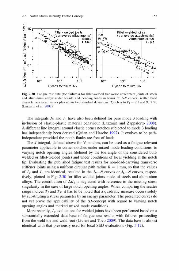
The integrals JV and JL have also been defined for pure mode 3 loading withinclusion of elastic-plastic material behaviour (Lazzarin and Zappalorto 2008).A different line integral around elastic corner notches subjected to mode 3 loadinghas independently been derived (Quian and Hasebe 1997). It evolves to be path-independent provided the notch flanks are free of loads.
The J-integral, defined above for V-notches, can be used as a fatigue-relevantparameter applicable to corner notches under mixed mode loading conditions, tovarying notch opening angles (defined by the toe angle of the considered butt-welded or fillet-welded joints) and under conditions of local yielding at the notchtip. Evaluating the published fatigue test results for non-load-carrying transversestiffener joints using a uniform circular path radius R = 1 mm, so that the valuesof JV and JL are identical, resulted in the JV-N curves or JL-N curves, respec-tively, plotted in Fig. 2.30 for fillet-welded-joints made of steels and aluminiumalloys. The contribution of DK2 is neglected with reference to the missing stresssingularity in the case of large notch opening angles. When comparing the scatterrange indices TJ and TK, it has to be noted that a quadratic increase occurs solelyby substituting a stress parameter by an energy parameter. The presented curves donot yet prove the applicability of the DJ-concept with regard to varying notchopening angles and marked mixed mode conditions.
More recently, JV evaluations for welded joints have been performed based on asubstantially extended data base of fatigue test results with failures proceedingfrom the weld toe and weld root (Livieri and Tovo 2009). The data base is almostidentical with that previously used for local SED evaluations (Fig. 3.12).
Fig. 2.30 Fatigue test data (toe failures) for fillet-welded transverse attachment joints of steelsand aluminium alloys under tensile and bending loads in terms of J–N curves; scatter bandcharacterises mean values plus minus two standard deviations; TJ refers to Pf = 2.3 and 97.7 %;(Lazzarin et al. 2002)
2.3 Notch Stress Intensity Factor Concept 155

2.3.9 Conclusions
The NSIFs K1, K2 and K3 together with the non-singular stress componentsdescribe the stress field in the close vicinity of pointed V-notches or re-entrantcorners. A transverse singular effect coupled with mode 2 loading at free surfacesis additionally identified. The numerical basis of NSIF evaluations in configura-tions with finite boundaries is the FE analysis method performed with extremelyfine meshes.
The NSIF concept is well suited to describe the fatigue strength of fillet-weldedand butt-welded joints with failure initiation at the weld toe. A uniform K–N curvewith sufficiently low scatter range is derived which includes the size or platethickness effect. Alternatively, a presentation in terms of the endurable J-integralis possible. Equivalent NSIFs are derived for cases of mixed mode loadingconditions.
The NSIF parameters are well suited to constitute the basis of the endurableaverage strain energy density at weld notch tips which is under discussion to beimplemented in the IIW recommendations for fatigue assessment.
2.4 Generalised Notch Stress Intensity Factor Concept
2.4.1 Survey of Section Contents
The notch stress intensity factor (NSIF) concept referring to pointed V-notch tipswith inclusion of the conventional stress intensity factor (SIF) approach referringto pointed crack tips is extended to the generalised notch stress intensity factorconcept referring to sharply rounded (blunt) or root-holed V-notches or crack tips.Notch rounding changes the stresses at the V-notch or crack tip substantiallyinsofar as the stress singularity is removed. But the stress distribution connectedwith the singularity remains widely unchanged at distances from the notch rootlarger than one half of the notch radius q, provided the radius is sufficiently smallin relation to the notch depth or crack length (sharp notches).
It is shown that the stress distribution at sharply rounded notches subjected tothe loading modes 1, 2, 3 can be described by the generalised NSIFs K1q, K2q, K3q
as the governing field parameters. These NSIFs are related to the maximum notchstresses rmax, smax, s�max which constitute the conventional stress concentrationfactors (SCFs) in engineering science. In contrast to the SCFs, the generalisedNSIFs describe not only the maximum stress but the whole stress field in thevicinity of the notch root. The field information is needed for assessing failureprocesses such as crack initiation and propagation or microstructural damagingphenomena.
In the following, the stress field equations for blunt V-notches subjected to thethree basic loading modes are given. The corresponding generalised NSIFs are
156 2 Extended Stress Intensity Factor Concepts
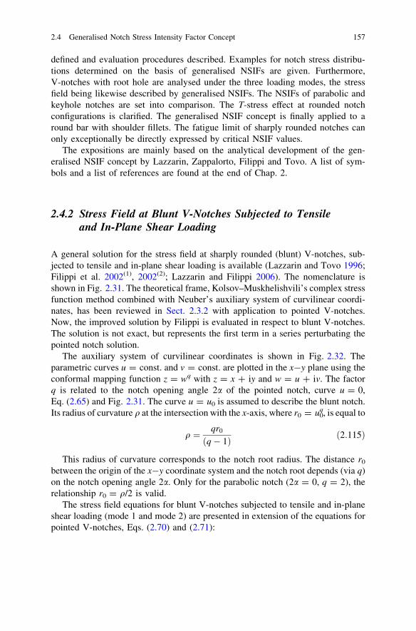
defined and evaluation procedures described. Examples for notch stress distribu-tions determined on the basis of generalised NSIFs are given. Furthermore,V-notches with root hole are analysed under the three loading modes, the stressfield being likewise described by generalised NSIFs. The NSIFs of parabolic andkeyhole notches are set into comparison. The T-stress effect at rounded notchconfigurations is clarified. The generalised NSIF concept is finally applied to around bar with shoulder fillets. The fatigue limit of sharply rounded notches canonly exceptionally be directly expressed by critical NSIF values.
The expositions are mainly based on the analytical development of the gen-eralised NSIF concept by Lazzarin, Zappalorto, Filippi and Tovo. A list of sym-bols and a list of references are found at the end of Chap. 2.
2.4.2 Stress Field at Blunt V-Notches Subjected to Tensileand In-Plane Shear Loading
A general solution for the stress field at sharply rounded (blunt) V-notches, sub-jected to tensile and in-plane shear loading is available (Lazzarin and Tovo 1996;Filippi et al. 2002(1), 2002(2); Lazzarin and Filippi 2006). The nomenclature isshown in Fig. 2.31. The theoretical frame, Kolsov–Muskhelishvili’s complex stressfunction method combined with Neuber’s auxiliary system of curvilinear coordi-nates, has been reviewed in Sect. 2.3.2 with application to pointed V-notches.Now, the improved solution by Filippi is evaluated in respect to blunt V-notches.The solution is not exact, but represents the first term in a series perturbating thepointed notch solution.
The auxiliary system of curvilinear coordinates is shown in Fig. 2.32. Theparametric curves u = const. and v = const. are plotted in the x-y plane using theconformal mapping function z = wq with z = x ? iy and w = u ? iv. The factorq is related to the notch opening angle 2a of the pointed notch, curve u = 0,Eq. (2.65) and Fig. 2.31. The curve u = u0 is assumed to describe the blunt notch.Its radius of curvature q at the intersection with the x-axis, where r0 = u0
q, is equal to
q ¼ qr0
ðq� 1Þ ð2:115Þ
This radius of curvature corresponds to the notch root radius. The distance r0
between the origin of the x-y coordinate system and the notch root depends (via q)on the notch opening angle 2a. Only for the parabolic notch (2a = 0, q = 2), therelationship r0 = q/2 is valid.
The stress field equations for blunt V-notches subjected to tensile and in-planeshear loading (mode 1 and mode 2) are presented in extension of the equations forpointed V-notches, Eqs. (2.70) and (2.71):
2.4 Generalised Notch Stress Intensity Factor Concept 157

rh
rr
srh
8
>
<
>
:
9
>
=
>
;
1
¼ 1ffiffiffiffiffiffi
2pp rk1�1K1
ð1þ k1Þ þ v1ð1� k1Þ
�ð1þ k1Þ cosð1� k1Þhð3� k1Þ cosð1� k1Þhð1� k1Þ sinð1� k1Þh
8
>
<
>
:
9
>
=
>
;
2
6
4
þ v1ð1� k1Þcosð1þ k1Þh� cosð1þ k1Þh
sinð1þ k1Þh
8
>
<
>
:
9
>
=
>
;
þ r
r0
� �l1�k1
ð3� k1Þ � v1ð1� k1Þ½ �cosð1þ l1Þh� cosð1þ l1Þh
sinð1þ l1Þh
8
>
<
>
:
9
>
=
>
;
3
7
5
ð2:116Þ
Fig. 2.32 Auxiliary systemof curvilinear coordinatesapplied to solve the stressfield problem at V-notches orhyperbolic notches; (Lazzarinand Tovo 1996)
Fig. 2.31 Coordinate systems, symbols and in-plane notch stress components at pointed V-notch(a) and at the corresponding rounded V-notch (b); with r0 = q(q - 1)/q; (Lazzarin and Tovo 1998)
158 2 Extended Stress Intensity Factor Concepts

rh
rr
srh
8
>
<
>
:
9
>
=
>
;
2
¼ 1ffiffiffiffiffiffi
2pp rk2�1K2
ð1þ k2Þ þ v2ð1� k2Þ
��ð1þ k2Þ cosð1� k2Þh�ð3� k2Þ cosð1� k2Þhð1� k2Þ sinð1� k2Þh
8
>
<
>
:
9
>
=
>
;
þ v2ð1� k2Þ� sinð1þ k2Þhsinð1þ k2Þhcosð1þ k2Þh
8
>
<
>
:
9
>
=
>
;
2
6
4
3
7
5
� r
r0
� �l2�k2
ð1� k2Þ þ v2ð1þ k2Þ½ �sinð1þ l2Þh� sinð1þ l2Þhcosð1þ l2Þh
8
>
<
>
:
9
>
=
>
;
3
7
5
ð2:117Þ
The NSIFs K1 and K2 are determined for r ! 0 according to Gross–Mendel-son’s limit value definition, Eqs. (2.77) and (2.78). Several well known solutionsfor crack or notch configurations (Williams 1952; Irwin 1957; Creager and Paris1967; Glinka and Newport 1987) can be considered as special cases of the abovegeneral solution, in which the NSIFs K1 and K2 may be substituted by theparameters a1 and a2 or by the maximum stresses rmax at the notch tip and smax
ahead of the notch tip.Williams’ solution for pointed V-notches results with r0 = 0 (because q = 0),
compare Eqs. (2.70) and (2.71). Westergaard–Sneddon–Irwin’s solution for cracktips is derived with r0 = 0, q = 2 and k1 = k2 = 0.5 (because 2a = 0), compareEqs. (2.2) and (2.4). Creager’s blunt crack (or parabolic notch) solution is obtainedby imposing r0 = q/2, q = 2, k1 = k2 = 0.5 and l1 = l2 = -0.5 (Creager andParis 1967):
rh
rr
srh
8
<
:
9
=
;
1
¼ KIffiffiffiffiffiffiffiffi
2prp 1
4
3 cos h=25 cos h=2sin h=2
8
<
:
9
=
;
þcos 3h=2� cos 3h=2
sin 3h=2
8
<
:
9
=
;
2
4
3
5þ q2r
cos h=2� cos h=2
sin h=2
8
<
:
9
=
;
0
@
1
A
ð2:118Þ
rh
rr
srh
8
<
:
9
=
;
2
¼ KIIffiffiffiffiffiffiffiffi
2prp 1
4
3 sin h=25 sin h=2cos h=2
8
<
:
9
=
;
þ3 sin 3h=2�3 sin 3h=23 cos 3h=2
8
<
:
9
=
;
2
4
3
5þ q2r
sin h=2� sin h=2cos h=2
8
<
:
9
=
;
0
@
1
A
ð2:119Þ
It can also be shown that Neuber’s solution for the stress distribution along thenotch bisector for tensile loaded V-notches is in agreement with Eq. (2.116) to awide extent (Lazzarin and Tovo 1996).
The general stress field equations above, Eqs. (2.116) and (2.117), areapproximations. They are deficient in accuracy, when applied to blunt V-notcheswith a large notch opening angle, e.g. 2a = 135� referring to weld toes. With theaim of improving the accuracy of the analytical solution, the part of the equations
2.4 Generalised Notch Stress Intensity Factor Concept 159

with the exponent l is extended. This is achieved by adding a second analyticalfunction to the first expression in Eq. (2.63), in order to provide further freeparameters for adjustment to the boundary conditions (Filippi et al. 2002(2)):
u zð Þ ¼ azk þ dzl; w zð Þ ¼ bzk þ czl ð2:120Þ
The resulting stress field equations are more complex than before in the secondorder terms which contain the exponent l, but the accuracy of the solution issubstantially enhanced, especially for large notch opening angles. An additionalimprovement of the exponent l2 for mode 2 loading has been introduced (Lazzarinet al. 2011).
2.4.3 Stress Field at Blunt V-Notches Subjected to Out-of-PlaneShear Loading
A general solution for the stress field at sharply rounded (blunt) V-notches sub-jected to out-of-plane shear loading has been derived on a similar analytical basisas before in the case of tensile and in-plane shear loading (Smith 2004; Zappalortoand Lazzarin 2011(3)). Pointed V-notches are included.
Only one analytical function (consisting of two terms) is needed for themathematical description of the shear stress field:
H zð Þ ¼ azk þ bzl ð2:121Þ
where the coefficients a and b are complex whereas the exponents k and l are real.The coefficients are introduced as real if only the antimetric part of the solution isrequested. The pointed notch problem is described by neglecting the second termwith the exponent l. The reason for one analytical function being sufficient is, thatthe out-of-plane stress field is governed by a potential function whereas the in-plane stress fields must obey a bipotential function.
The out-of-plane shear stresses are derived in the following form, separated intoantimetrical (subscript a) and symmetrical (subscript s) parts in the r-h coordinatesystem:
sr z
sh z
� �
¼KðaÞ3qffiffiffiffiffiffi
2pp rka�1 sin kah
cos kah
� �
þKðsÞ3qffiffiffiffiffiffi
2pp rks�1 cos ksh� r=r0ð Þls�ks cos lsh
� sin kshþ r=r0ð Þls�ks sin lsh
� �
ð2:122Þ
where the antimetric and symmetric eigenvalues are dependent on the notch openingangle 2a expressed by the parameter q ranging between 2.0 and 1.0, Eq. (2.65):
ka ¼1q; ks ¼
2q; ls ¼
1q; q ¼ 2p� 2a
pð2:123Þ
160 2 Extended Stress Intensity Factor Concepts

The generalised NSIFs KðaÞ3q and KðsÞ3q are determined from the stresses in thebisector plane (h = 0) of the blunt V-notch (with r0+ [ r0 in the logarithmic plot):
KðaÞ3q ¼ limr!r0þ
ffiffiffiffiffiffi
2pp
r1�kash zðr; 0Þ� �
ð2:124Þ
KðsÞ3q ¼ limr!r0þ
ffiffiffiffiffiffi
2pp r1�kssr zðr; 0Þ
1� ðr=r0Þls�ks
" #
ð2:125Þ
The above NSIF KðaÞ3q can be substituted by the maximum notch stress,
KðaÞ3q ¼ sðaÞmaxr1�ka
0 ð2pÞ1=2 with r0 = (1 - 1/q)q (Zappalorto et al. 2009), whereas this
is not possible with the NSIF KðsÞ3q :
For the pointed V-notch, notch radius q and distance r0 are equal to zero, so thatthe terms with r/r0 disappear (the exponent, ls - ks, is negative):
sr z
sh z
� �
¼ KðaÞ3ffiffiffiffiffiffi
2pp rka�1 sin kah
cos kah
� �
þ KðsÞ3ffiffiffiffiffiffi
2pp rks�1 cos ksh
� sin ksh
� �
ð2:126Þ
The exponent (ka - 1) is negative, thus characterising a singular stress distri-bution. The other exponent (ks - 1) is positive, thus denoting a non-singulardistribution. In the case of a crack or slit (2a = 0), the eigenvalues are ka = 1/2and ks = 1.0, the exponents being (ka - 1) = -1/2 and (ks - 1) = 0, Eq. (2.123)with q = 2. Comparison with Eq. (2.73) gives the non-singular S-stress,
S ¼ KðsÞ3 rks�1=ð2pÞ1=2:
In order to improve the solution for U-notches and blunt V-notches subjected toout-of-plane shear loading, a modified mapping function has been introducedwhich complies better with the actual notch shape consisting of a circular arctapering off into the rectilinear flanks of the V-notch (Zappalorto et al. 2010). Theresulting, more complex stress field equations have been derived. It is found thatthe notch stresses are markedly influenced by the details of the notch root shape.A solution for semi-elliptical notches is also available (Lazzarin et al. 2007).In both investigations the NSIFs are found by FE analysis.
2.4.4 Generalised Notch Stress Intensity Factors
For evaluating the stress fields at blunt V-notches, generalised notch stressintensity factors have to be introduced which may be differently defined dependingon the type of notch geometry. Also, the simple SIFs or NSIFs may be used. Forexample, in Eqs. (2.116) and (2.117) the NSIFs K1 and K2 of the correspondingpointed notch are introduced, or in Eqs. (2.118) and (2.119) the SIFs KI and KII ofthe corresponding pointed crack tip. It has to be noted, that the distance r0 ismeasured between the origin of r and the pointed or rounded notch or crack tip.
2.4 Generalised Notch Stress Intensity Factor Concept 161
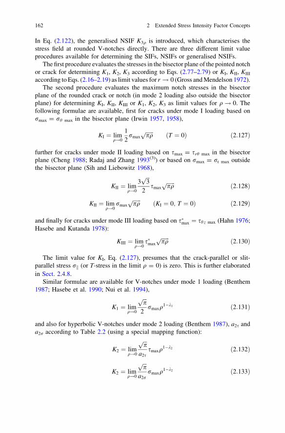
In Eq. (2.122), the generalised NSIF K3q is introduced, which characterises thestress field at rounded V-notches directly. There are three different limit valueprocedures available for determining the SIFs, NSIFs or generalised NSIFs.
The first procedure evaluates the stresses in the bisector plane of the pointed notchor crack for determining K1, K2, K3 according to Eqs. (2.77–2.79) or KI, KII, KIII
according to Eqs. (2.16–2.19) as limit values for r ! 0 (Gross and Mendelson 1972).The second procedure evaluates the maximum notch stresses in the bisector
plane of the rounded crack or notch (in mode 2 loading also outside the bisectorplane) for determining KI, KII, KIII or K1, K2, K3 as limit values for q! 0. Thefollowing formulae are available, first for cracks under mode I loading based onrmax = rh max in the bisector plane (Irwin 1957, 1958),
KI ¼ limq!0
12rmax
ffiffiffiffiffiffi
pqp ðT ¼ 0Þ ð2:127Þ
further for cracks under mode II loading based on smax = srh max in the bisectorplane (Cheng 1988; Radaj and Zhang 1993(3)) or based on rmax = rt max outsidethe bisector plane (Sih and Liebowitz 1968),
KII ¼ limq!0
3ffiffiffi
3p
2smax
ffiffiffiffiffiffi
pqp ð2:128Þ
KII ¼ limq!0
rmax
ffiffiffiffiffiffi
pqp ðKI ¼ 0; T ¼ 0Þ ð2:129Þ
and finally for cracks under mode III loading based on s�max ¼ sh z max (Hahn 1976;Hasebe and Kutanda 1978):
KIII ¼ limq!0
s�max
ffiffiffiffiffiffi
pqp ð2:130Þ
The limit value for KI, Eq. (2.127), presumes that the crack-parallel or slit-parallel stress rk (or T-stress in the limit q = 0) is zero. This is further elaboratedin Sect. 2.4.8.
Similar formulae are available for V-notches under mode 1 loading (Benthem1987; Hasebe et al. 1990; Nui et al. 1994),
K1 ¼ limq!0
ffiffiffi
pp
2rmaxq
1�k1 ð2:131Þ
and also for hyperbolic V-notches under mode 2 loading (Benthem 1987), a2s anda2r according to Table 2.2 (using a special mapping function):
K2 ¼ limq!0
ffiffiffi
pp
a2ssmaxq
1�k2 ð2:132Þ
K2 ¼ limq!0
ffiffiffi
pp
a2rrmaxq
1�k2 ð2:133Þ
162 2 Extended Stress Intensity Factor Concepts

Table 2.3 Parameter values for evaluation of K1q and K2q according to Eqs. (2.135) and (2.136);(Lazzarin and Filippi 2006)
2a q k1 k2 l1 l2 ~x1 ~x2
0� 2.0 0.500 0.500 -0.500 -0.500 1.000 -1.030� 1.833 0.501 0.598 -0.456 -0.447 1.034 -1.045� 1.750 0.505 0.660 -0.432 -0.412 1.014 -1.060� 1.667 0.512 0.731 -0.406 -0.373 0.970 -1.090� 1.500 0.545 0.909 -0.345 -0.288 0.810 -1.0120� 1.333 0.616 1.149 -0.268 -0.198 0.570 -1.0135� 1.250 0.674 1.302 -0.220 -0.151 0.432 -1.0
Table 2.2 Parameter values for Benthem’s NSIF K2 of pointed V-notches, Eqs. (2.132) and(2.133); (Benthem 1987)
2a k2 a2s a2r 2a k2\ a2s a2r
0� 0.500 0.385 1.000 90� 0.909 0.620 1.21330� 0.598 0.492 1.242 102.54� 1.000 0.707 1.17960� 0.731 0.550 1.275
and finally for V-notches under mode 3 loading in analogy to Eq. (2.130):
K3 ¼ limq!0
ffiffiffi
pp
s�maxq1�k3 ð2:134Þ
The Eqs. (2.127–2.134) above may be used without the limes with distinct finitevalues of q in an approximative manner, but the convergence behaviour must bechecked (compare Figs. 1.32 and 1.33).
The third procedure evaluates the stresses in the bisector plane of the roundednotch or crack for determining K1q, K2q, K3q as the limit values for r ! r0
(or r ! r0þ, the position of srh max in mode 2 loading) which may be combinedwith averaging these NSIFs over a small distance ahead of the notch root. Thefollowing formulae are derived for V-notches inclusive of cracks (Lazzarin andFilippi 2006; Zappalorto et al. 2008), Table 2.3:
K1q ¼ limr!r0
ffiffiffiffiffiffi
2pp
r1�k1rhðr; 0Þ1þ ~x1ðr=r0Þl1�k1
¼ffiffiffiffiffiffi
2pp
r1�k10 rhðr0; 0Þ1þ ~x1
ð2:135Þ
K2q ¼ limr!r0þ
ffiffiffiffiffiffi
2pp
r1�k2srhðr; 0Þ1þ ~x2ðr=r0Þl2�k2
¼ffiffiffiffiffiffi
2pp
r1�k20 srhðr0þ; 0Þ
1� ðr0þ=r0Þl2�k2ð2:136Þ
K3q ¼ limr!r0
ffiffiffiffiffiffi
2pp
r1�k3sh zðr; 0Þ ¼ffiffiffiffiffiffi
2pp
r1�k30 sh zðr0; 0Þ ð2:137Þ
The value ~x2 ¼ �1 in Eq. (2.136) is part of the stress field solution. The limitvalue r ! r0þ instead of r ! r0 in mode 2 loading is proposed here in order toavoid numerical problems when introducing r = r0. An ‘equivalent V-notch’ maybe defined for other notch types (e.g. semicircular) based on Eq. (2.135); (Filippiand Lazzarin 2004).
2.4 Generalised Notch Stress Intensity Factor Concept 163

The NSIFs K1q, K2q, K3q differ from K1, K2, K3 for finite values of q. They aregenerally enlarged for increasing values of q. The following relationship should bevalid, because r0 / q :
Ki ¼ limq!0
Kiq ði ¼ 1; 2; 3Þ ð2:138Þ
The condition according to Lazzarin, that the enlarged values of K1q, K2q, K3q
can be used as characteristic stress field parameters at rounded notches (q[ 0), isthe constancy of K1q, K2q, K3q over a certain distance from the notch root. If thiscondition is met, the NSIF concept is applicable also to notches with a substan-tially increased notch radius.
In cases of a slightly (oscillating) dependence of K1q, K2q, K3q on (r - r0), thedistance from the notch root, the following averaging procedure is proposed(Lazzarin and Filippi 2006):
K iq ¼1gq
Z
r0þgq
r0
Kiqdr ði ¼ 1; 2; 3Þ ð2:139Þ
where g = 0.4 is a recommended choice. The averaging procedure is also pre-ferred in cases of a very small notch radius where sufficiently fine FE meshing atthe notch root is difficult to achieve.
Now the question arises, to what extent the stress field equations expressed by K1,K2, K3 or KI, KII, KIII can be used with the generally enlarged values of K1q, K2q, K3q.The answer depends on the considered case. As far as possible, the stress fieldequations should be used, from which the relationships for K1q, K2q, K3q were derived.
These relationships depend on the notch shape. Those mentioned above refer toV-notches or hyperbolic notches with the parabolic notch as a special case. Thecomparison of hyperbolic with circular arc V-notches reveals a slight difference evenin mode 1 loading (Savruk and Kazberuk 2010). The formulae for elliptical notchesare also different to some extent. The relationships for V-notches with root hole, thekeyhole notch among them, deviate even more. They will be presented in Sect. 2.4.6.
Not only the notch shape exerts an influence on the values of K1q, K2q, K3q, butalso the geometrical and dimensional parameters of the notched members as wellas its loading and support conditions. Cross-sectional weakening and notch-par-allel loading (or T-stress) are especially influential.
The generalised NSIFs K1q, K2q, K3q have potential for application insofar asthey define the stress field over a finite area (or volume), just as the simple NSIFs orSIFs do. The widely used stress concentration factors (SCFs) give only the maxi-mum stress at one point. Additional information on the stress field is needed, in orderto characterise the fatigue life or brittle fracture strength, e.g. notch stress averaging,notch stress gradient, critical distance among others. In contrast, the NSIFs (possiblysupplemented by the T-stress and S-stress terms) represent the complete notch stressfield without additional information being necessary. Whereas the SCFs are notapplicable to pointed notches, the NSIFs proceed from pointed notches.
164 2 Extended Stress Intensity Factor Concepts

The NSIFs in contrast to the SCFs also include the scale or size effect on brittlefracture or fatigue strength. Considering a small notched component, the notchwith radius q1, in comparison to a self-similar enlarged notched component, thenotch with radius q2, both components subjected to the same nominal stresses,
then the SCFs Kt are identical, but the NSIFs are related by ðq2=q1Þ1�k accordingto Eqs. (2.131–2.134). They define two stress profiles of different level ahead ofthe notch root starting with the same value of the maximum stress. One method todetermine failure-effective notch stresses is to average the notch stresses over adefinite, material-dependent microstructural support length. These averaged notchstresses will be higher for the larger component. Thus, in comparison with aconstant endurable averaged notch stress, the larger component with the higherNSIF will come off worse.
2.4.5 Evaluation Examples for Stresses at Blunt V-Notches
Some typical evaluation examples for the stresses at sharply rounded (blunt)V-notches subjected to tensile and in-plane shear loading are reviewed in thefollowing in order to achieve further clarity on the generalised NSIF concept.
In the first four figures, the determination of the NSIFs K1q and K2q (as far asrelevant) according to Eqs. (2.135) and (2.136) is exemplified. The tensile loaded flatbar with two-sided U-notch is considered in Fig. 2.33. A slight oscillation of K1q over(r - r0) occurs for q = 0 in the evaluation range up to (r - r0) = 1 mm. The valueof K1q rises with the ratio q/a (with notch depth a), as specified further below. Theoscillation is enlarged for the V-notch with 2a = 135�, while the influence of q/a isreduced, Fig. 2.34. Mixed mode loading conditions occur in the bisector plane of theshoulder fillet flat bar in Fig. 2.35 and of the weld-like flat bar in Fig. 2.36. Oncemore, some variability of K1q or K2q is detected in the evaluation range.
The stress distribution in the notch bisector ahead of the notch root in a tensileloaded V-notched flat bar is plotted in Fig. 2.37 for three notch opening angles.Original and K1q-based analysis results are compared. A first curve segment up to0.1 mm is mainly controlled by the maximum notch stress. A second segment upto 5 mm presents the gradient of the corresponding pointed notch configuration.The third segment correlates with the nominal stress, actually in the net cross-section. Another similar diagram, where the notch radius is varied, is shown inFig. 2.38. The averaged solution for K1q is evaluated. The first curve segment islimited by (r - r0)/q & 0.1. The nominal stress is related to the net cross-section.
The linearised rise of K1q/K1 over the ratio of notch radius to notch depth, q/a, isshown in Fig. 2.39 and also by Table 2.4. Actually, the curves should start atK1q/K1q = 1.0 for q/a = 0, which is suppressed by the linearisation, compareEq. (2.138). The result is independent on b/a for sufficiently large values of this ratio.
Corresponding results for in-plane shear loading are recorded in subsequentgraphs. The analysed configuration is a rectangular plate with a two-sided internalparabolic, hyperbolic, U-shaped or V-shaped notch, the plate subjected to
2.4 Generalised Notch Stress Intensity Factor Concept 165

Fig. 2.34 Normalised NSIF K1q dependent on distance from V-notch root, (r - r0), Eq. (2.135)for 2a = 135�; evaluation of FE analysis results; (Lazzarin and Filippi 2006)
Fig. 2.33 Normalised NSIF K1q dependent on distance from U-notch root, (r - r0), Eq. (2.135)for 2a = 0�; evaluation of FE analysis results; (Lazzarin and Filippi 2006)
166 2 Extended Stress Intensity Factor Concepts

Fig. 2.36 Normalised NSIFs K1q and K2q dependent on distance from corner notch root, (r - r0),Eqs. (2.135) and (2.136) for 2a = 135�; evaluation of FE analysis results; (Lazzarin and Filippi2006(1))
Fig. 2.35 Normalised NSIFs K1q and K2q dependent on distance from corner notch root, (r - r0),Eqs. (2.135) and (2.136) for 2a = 90�; evaluation of FE analysis results; (Lazzarin and Filippi 2006)
2.4 Generalised Notch Stress Intensity Factor Concept 167

Fig. 2.38 Stress rh in notch bisector over distance from V-notch root, (r - r0); direct comparedwith K1q-based FE analysis results; K1q according to Eq. (2.139) with finite values of q; (Lazzarinand Tovo 1996)
Fig. 2.37 Stress rh in notch bisector ahead of the V-notch root, notch radius q = 3.2 mm, forthree notch opening angles 2a; original compared with K1q-based FE analysis results; K1q/K1
approximated according to Eq. (2.139) and Table 2.4; (Lazzarin and Filippi 2006)
168 2 Extended Stress Intensity Factor Concepts

prescribed remote edge displacements u0 and v0 together with shear-compatiblesupport conditions in the two geometrical symmetry planes, Fig. 2.40. The refer-ence stress s0 is produced in the rectangular plate without the notch. It is smallerthan the nominal stress in the gross cross-section of the plate with the internal notch.
At first, parabolic and hyperbolic notches are considered. The curves of K2q/s0
over distance from the notch root for the hyperbolic notch (2a = 60�), Fig. 2.41,show that K2q is substantially enlarged even for small values of q, e.g. q = 0.1 mm.The corresponding shear stresses in the bisector are plotted in Fig. 2.42. The curvesrun asymptotically to the straight line of the pointed notch. The FE analysis results ofthe parabolic and hyperbolic notches have also been evaluated using K2q accordingto Eq. (2.139). The parabolic notch results are set in comparison to K2q(smax)according to Eq. (2.128) with KII substituted by K2q (Cheng 1988). Additionally,the maximum principal stresses at the notch edge corresponding to the maximumtangential stress are compared, Table 2.5. The correspondence is satisfactory.
The rise of K1q/K2 over the ratio of notch radius to notch depth, q/a, is shownin Fig. 2.43 for parabolic and hyperbolic notches. All the curves converge toK2q/K2 = 1.0 for q/a = 0, as demanded by Eq. (2.138). The rise is strongest forthe parabolic notch.
Table 2.4 Parameter values for the approximation of K1q/K1 = u ? w(q/a) for V-notched flatbar; different notch opening angles 2a; net cross-sectional width 2b to notch depth a ratios2b/a = 2, 5, 10, 50 (Lazzarin and Filippi 2006)
2a 30� 45� 60� 90� 120� 135�u 1.043 1.025 1.014 1.011 1.023 1.026w 0.241 0.226 0.200 0.127 0.051 0.025
Fig. 2.39 NSIF ratio K1q/K1 dependent on the ratio of V-notch radius to V-notch depth, q/a,based on FE analysis results; various notch opening angles 2a; (Lazzarin and Filippi 2006)
2.4 Generalised Notch Stress Intensity Factor Concept 169
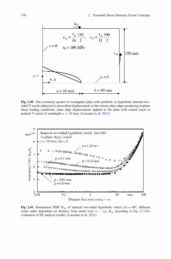
Fig. 2.41 Normalised NSIF K2q of internal two-sided hyperbolic notch (2a = 60�, differentnotch radii) dependent on distance from notch root, (r - r0), K2q according to Eq. (2.136);evaluation of FE analysis results; (Lazzarin et al. 2011)
Fig. 2.40 One symmetry quarter of rectangular plate with parabolic or hyperbolic internal two-sided V-notch subjected to prescribed displacements at the remote plate edges producing in-planeshear loading conditions; same edge displacements applied to the plate with central crack orpointed V-notch of semidepth a = 10 mm; (Lazzarin et al. 2011)
170 2 Extended Stress Intensity Factor Concepts

At second, the U-notch and V-notches are analysed, using the K2q formula ofroot holes, Eq. (2.144). It was found that this formula is more accurate than thecorresponding formula for hyperbolic (and parabolic) notches, Eq. (2.136), whichshifts the position of srh max closer to the notch root. The curves K2q/s0 overdistance (r - r0) from the notch root for the U-notch, Fig. 2.44, show that K2q issubstantially enlarged only for larger values of q (q/a C 0.1). The correspondingshear stresses in the bisector are plotted in Fig. 2.45. The curves are identical up tothe maximum stress and then deviate in approximation of the nominal stress in thenet cross-section with the exception of the K2q-based solid line which presumes aninfinitely wide cross-section.
Table 2.5 Generalised NSIFs of two-sided parabolic notch (k2 = 0.5) in rectangular platesubjected to in-plane shear loading; K2q averaged over 0.4q, Eq. (2.139), or based on smax,Eq. (2.128); additionally maximum principal (or tangential) stresses at notch edge; deviationsDK ¼ ðK2q;s=K2q � 1Þ � 100 and Dr ¼ ðr1 max;K=r1 max;FE � 1Þ � 100; (Lazzarin et al. 2011)
q[mm]
srh max,FE
[MPa]K2q
[MPa mm0.5]K2q,s[MPa mm0.5]
DK [%] r1max,FE
[MPa]r1 max;K
[MPa]Dr
[%]
0.01 1306.1 596.0 601.5 0.92 3204.0 3211.0 0.220.10 465.8 677.0 678.2 0.18 1204.5 1207.9 0.280.50 249.3 809.6 811.8 0.27 639.2 646.0 1.051.25 190.3 977.7 979.8 0.21 477.8 493.4 3.262.50 159.5 1177.5 1161.3 -1.37 405.6 420.2 3.594.00 145.8 1376.2 1342.8 -2.43 370.6 388.2 4.75
Fig. 2.42 Shear stress srh in notch bisector over distance from notch root, (r - r0); internal two-sided hyperbolic notch (2a = 60�, different notch radii), in-plane shear loaded; direct comparedwith K2q-based FE analysis results; K2q according to Eq. (2.136) averaged by Eq. (2.139);(Lazzarin et al. 2011)
2.4 Generalised Notch Stress Intensity Factor Concept 171
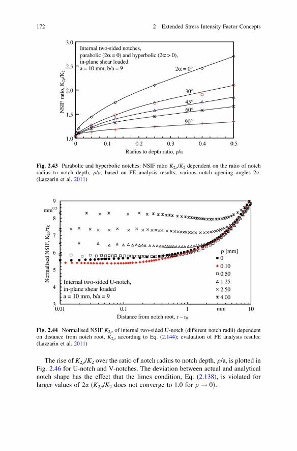
The rise of K2q/K2 over the ratio of notch radius to notch depth, q/a, is plotted inFig. 2.46 for U-notch and V-notches. The deviation between actual and analyticalnotch shape has the effect that the limes condition, Eq. (2.138), is violated forlarger values of 2a (K2q/K2 does not converge to 1.0 for q! 0Þ:
Fig. 2.44 Normalised NSIF K2q of internal two-sided U-notch (different notch radii) dependenton distance from notch root, K2q according to Eq. (2.144); evaluation of FE analysis results;(Lazzarin et al. 2011)
Fig. 2.43 Parabolic and hyperbolic notches: NSIF ratio K2q/K2 dependent on the ratio of notchradius to notch depth, q/a, based on FE analysis results; various notch opening angles 2a;(Lazzarin et al. 2011)
172 2 Extended Stress Intensity Factor Concepts

Finally, the notch stress curves for a quadratic plate specimen with one-sidedV-notch, used for brittle fracture testing of brittle materials, are drawn in Fig. 2.47.The notch opening angle 2a = 45� is fixed, the V-notch radius q is varied between0 and 1 mm. The tensile forces F produce superimposed nominal tensile and
Fig. 2.46 U-notch and V-notches: NSIF ratio K2q/K2 dependent on the ratio of notch radius tonotch depth, q/a, based on FE analysis results evaluated by Eq. (2.144); various notch openingangles 2a; (Lazzarin et al. 2011)
Fig. 2.45 Shear stress srh in notch bisector over distance from notch root, (r - r0); internal two-sided U-notch (different notch radii), in-plane shear loaded; direct compared with K2q-based FEanalysis results; K2q according to Eq. (2.144); (Lazzarin et al. 2011)
2.4 Generalised Notch Stress Intensity Factor Concept 173

Fig. 2.48 SFCs of internal two-sided rounded V-notches (‘rhombic cutouts’) dependent on notchopening angle a02 for various ratios r2/b of notch radius to notch depth; infinite plate subjected toremote tensile loading; results by functional analysis; (Radaj and Schilberth 1977)
Fig. 2.47 Stress rh in notch bisector over distance from notch root, x; one-sided roundedV-notches in comparison to pointed V-notch in square plate; notch opening angle 2a = 45�;(Nui et al. 1994)
174 2 Extended Stress Intensity Factor Concepts

bending stresses in the net cross-section. The solution of the stress field problemhas been achieved based on Kolosov–Muskhelishvili’s complex stress functionmethod combined with conformal mapping of the polygonal plate area onto theunit circle by applying the Schwartz–Christoffel transformation (Nui et al. 1994).For evaluating the notch stress at the pointed notch, Williams’ singularity expo-nents are introduced. It is demonstrated that the maximum notch stresses in theclose neighbourhood of the notch root, (r - r0)/q B 0.2, depend predominantly onthe notch radius, whereas outside this region, the notch opening angle is decisive,as given by the pointed notch solution. It is visible from the graph, that the roundednotch curves run slightly above the pointed notch curve, which indicates K1q [ K1.
It is also shown more generally and in quantitative terms that the intermediateNSIF-governed stress field may be used to characterise the yielding or strengthbehaviour of sharply rounded notches (Nui et al. 1994; Dini and Hills 2004). Thisfield is intermediate between the maximum notch stress governed near-field andthe nominal stress governed far-field.
This subsection with the evaluation examples for the notch stresses at roundedV-notches is closed with two diagrams showing the SCFs of internal two-sidedV-notches (‘rhombic cutouts’) in the infinite plate subjected to remote in-planetensile and shear loading, Figs. 2.48 and 2.49; (Radaj and Schilberth 1977).
These SCFs have been determined very accurately based on complex analyticalstress functions according to Kolosov–Muskhelishvili, combined with conformalmapping of the rhombic cutout with rounded V-notches according to Schwartz–Christoffel. A polygonal shape is considered, consisting of straight lines and
Fig. 2.49 SFCs of internal two-sided rounded V-notches (‘rhombic cutouts’) dependent on notchopening angle a02 for various ratios r2/b of notch radius to notch depth; infinite plate subjected toremote in-plane shear loading; results by functional analysis; (Radaj and Schilberth 1977)
2.4 Generalised Notch Stress Intensity Factor Concept 175

circular arcs. The circular arcs are approximated by multi-corner polygons. Theirseries expansion as a mapping function is truncated, so that the corners aresmoothed. The NSIF concept is not applied.
The SCFs are primarily dependent on the ratio r2/b of notch radius to notchdepth. They may additionally depend on the notch opening angle a02. In tensileloading, the latter dependency is marked only for a02 C 90�. In shear loading, theSCFs decrease rapidly with increasing values of a02 [ 0�. They reach theirmaximum at a02 = 108�. This angle corresponds to the limit value for singularstresses in mode 2 loading of pointed V-notches, 2a = 102.6�. Actually, the curvepoints were calculated in steps of Da02 = 18�, so that a02 = 108� is the curvepoint nearest to the no-singularity angle.
The NSIF concept needs the FE analysis as basis for evaluations in engineeringapplications. Parametric investigations, as just considered above, would necessi-tate variation of the geometrical parameters in the FE model before addressing theNSIF behaviour. To the author’s knowledge, no such investigations have beenperformed up to now. Deviations from the SCF behaviour will predominantly becaused by a varying stress gradient normal to the notch root. This gradient isprimarily dependent on the reciprocal value of q and only occasionally on thenotch opening angle to a larger extent.
2.4.6 Stress Field at V-Notches with Root Hole
V-notches with root hole and the special case of the keyhole are rarely used inengineering designs. Here, blunt notches with a smooth transition from the rec-tilinear to the circular notch edge are preferred, because they produce lower notchstresses and are easier to produce. On the other hand, they are an important designwithin the theoretical frame of stress analysis. They allow an easier handling ofsolutions and they simulate the circular notch shape accurately, which is importantin those cases where the maximum notch stress occurs outside the bisector. Theadvantage of their use in NSIF considerations is, that the variation of the notchradius does not affect the other geometrical parameters of the notch. This is not thecase with elliptical, parabolic or hyperbolic notches.
First, tensile and in-plane shear loading is dealt with, then out-of-plane shearloading and finally the transverse (out-of-plane) shear loading effect produced byin-plane shear loading at load-free surfaces.
Fig. 2.50 V-notch with root hole,polar in-plane coordinate systemwith origin in centre of hole;(Zappalorto and Lazzarin 2011(1))
176 2 Extended Stress Intensity Factor Concepts
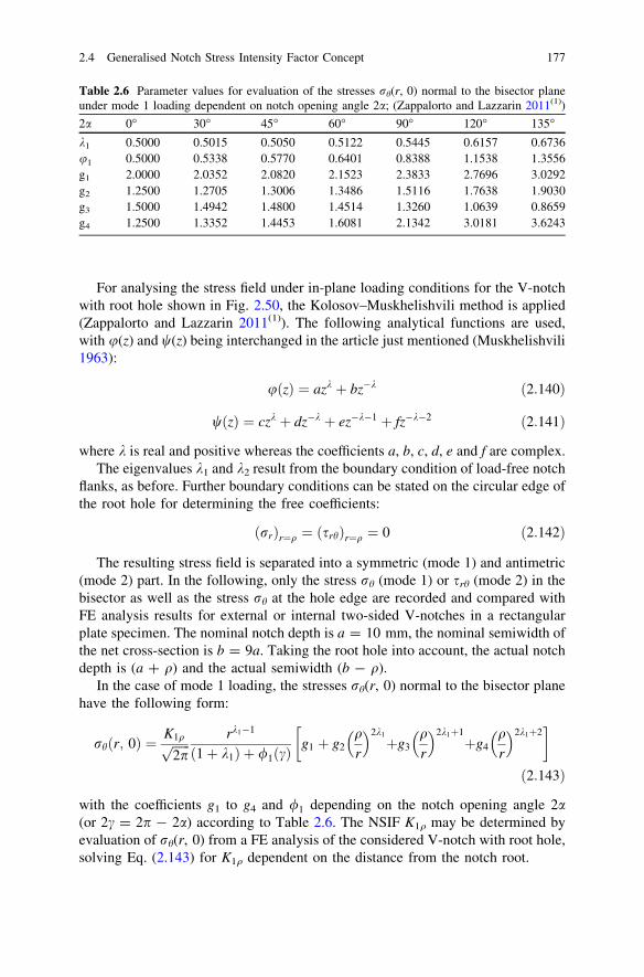
For analysing the stress field under in-plane loading conditions for the V-notchwith root hole shown in Fig. 2.50, the Kolosov–Muskhelishvili method is applied(Zappalorto and Lazzarin 2011(1)). The following analytical functions are used,with u(z) and w(z) being interchanged in the article just mentioned (Muskhelishvili1963):
uðzÞ ¼ azk þ bz�k ð2:140Þ
wðzÞ ¼ czk þ dz�k þ ez�k�1 þ fz�k�2 ð2:141Þ
where k is real and positive whereas the coefficients a, b, c, d, e and f are complex.The eigenvalues k1 and k2 result from the boundary condition of load-free notch
flanks, as before. Further boundary conditions can be stated on the circular edge ofthe root hole for determining the free coefficients:
ðrrÞr¼q ¼ ðsrhÞr¼q ¼ 0 ð2:142Þ
The resulting stress field is separated into a symmetric (mode 1) and antimetric(mode 2) part. In the following, only the stress rh (mode 1) or srh (mode 2) in thebisector as well as the stress rh at the hole edge are recorded and compared withFE analysis results for external or internal two-sided V-notches in a rectangularplate specimen. The nominal notch depth is a = 10 mm, the nominal semiwidth ofthe net cross-section is b = 9a. Taking the root hole into account, the actual notchdepth is (a ? q) and the actual semiwidth (b - q).
In the case of mode 1 loading, the stresses rh(r, 0) normal to the bisector planehave the following form:
rhðr; 0Þ ¼ K1qffiffiffiffiffiffi
2pp rk1�1
ð1þ k1Þ þ /1ðcÞg1 þ g2
qr
2k1
þg3qr
2k1þ1þg4
qr
2k1þ2� �
ð2:143Þ
with the coefficients g1 to g4 and /1 depending on the notch opening angle 2a(or 2c = 2p - 2a) according to Table 2.6. The NSIF K1q may be determined byevaluation of rh(r, 0) from a FE analysis of the considered V-notch with root hole,solving Eq. (2.143) for K1q dependent on the distance from the notch root.
Table 2.6 Parameter values for evaluation of the stresses rh(r, 0) normal to the bisector planeunder mode 1 loading dependent on notch opening angle 2a; (Zappalorto and Lazzarin 2011(1))
2a 0� 30� 45� 60� 90� 120� 135�k1 0.5000 0.5015 0.5050 0.5122 0.5445 0.6157 0.6736u1 0.5000 0.5338 0.5770 0.6401 0.8388 1.1538 1.3556g1 2.0000 2.0352 2.0820 2.1523 2.3833 2.7696 3.0292g2 1.2500 1.2705 1.3006 1.3486 1.5116 1.7638 1.9030g3 1.5000 1.4942 1.4800 1.4514 1.3260 1.0639 0.8659g4 1.2500 1.3352 1.4453 1.6081 2.1342 3.0181 3.6243
2.4 Generalised Notch Stress Intensity Factor Concept 177

In the case of mode 2 loading, the stresses srh(r, 0) in the bisector plane aregiven as follows:
srhðr; 0Þ ¼ K2qffiffiffiffiffiffi
2pp rk2�1 1þ h1
qr
2k2
þh2qr
2k2þ1þh3
qr
2k2þ2� �
ð2:144Þ
with the coefficients h1 to h3 depending on the notch opening angle 2a according toTable 2.7. The NSIF K2q may be determined by evaluation of srh(r, 0) from a FEanalysis of the considered V-notch with root hole, solving Eq. (2.144) for K2q
dependent on the distance from the notch root. Such an evaluation is shown inFig. 2.51. Identical values of K2q and K2 are found, evaluating Eq. (2.144) forq[ 0 in comparison to q = 0. The values are constant over a distance from thenotch root, where, with the evaluations for blunt V-notches hitherto considered,substantial variations and oscillations occur.
Fig. 2.51 V-notches with root hole: NSIFs K2q and K2 dependent on distance from notch root;evaluation based on Eq. (2.144); (Lazzarin et al. 2011)
Table 2.7 Parameter values for evaluation of the stresses srh(r, 0) in the bisector plane undermode 2 loading dependent on notch opening angle 2a; (Zappalorto and Lazzarin 2011(1))
2a 0� 30� 45� 60� 90� 120� 135�k2 0.5000 0.5982 0.6597 0.7309 0.9085 1.1489 1.3021h1 1.6250 1.6422 1.6639 1.6941 1.7782 1.8873 1.9451h2 -0.7500 -0.6011 -0.5393 -0.4849 -0.3921 -0.3079 -0.2614h3 -1.8750 -2.0411 -2.1246 -2.2092 -2.3861 -2.5794 -2.6837
178 2 Extended Stress Intensity Factor Concepts

Fig. 2.53 Tensile loaded V-notch with root hole: stress rh at hole edge; two notch openingangles 2a combined with different notch radii q; direct compared with K1q-based FE analysisresults; (Zappalorto and Lazzarin 2011(1))
Fig. 2.52 Tensile loaded V-notch with root hole: stress rh in notch bisector ahead of the notchroot; two notch opening angles 2a combined with different notch radii q; direct compared withK1q-based FE analysis results; (Zappalorto and Lazzarin 2011(1))
2.4 Generalised Notch Stress Intensity Factor Concept 179

Fig. 2.54 In-plane shear-loaded V-notch with root hole: stress srh in notch bisector ahead of thenotch root; two notch opening angles 2a combined with different notch radii q; direct comparedwith K2q-based FE analysis results; (Zappalorto and Lazzarin 2011(1))
Fig. 2.55 In-plane shear-loaded V-notch with root hole: stress rh at hole edge; two notchopening angles 2a combined with different notch radii q; direct compared with K2q-based FEanalysis results; (Zappalorto and Lazzarin 2011(1))
180 2 Extended Stress Intensity Factor Concepts

For q = 0 (pointed notches), K1q ! K1 and K2q ! K2, as demanded byEq. (1.138). The Eqs. (2.143) and (2.144) in the case of the keyhole (2a = 0) areidentical with those given in the literature (Kullmer 1992; Radaj et al. 2001).
The stresses rh in mode 1 loading evaluated from the FE model mentionedabove (converted to external notches) in the bisector plane (h = 0) and at the holeedge (r = q) are shown in Figs. 2.52 and 2.53. Direct FEM evaluation results arecompared with the analytical stress distributions based on identical values of rmax
or K1q. Some deviations are visible in the edge stress diagram, indicating theapproximative character of the analytical solution.
Fig. 2.56 V-notches with root hole: NSIF ratio K2q/K2 dependent on the ratio q/a of notch radiusto notch depth, based on FE analysis results; various notch opening angles 2a; (Lazzarin et al.2011(1))
Fig. 2.57 V-notch with root hole subjected to out-of-plane shear loading (only the antiplaneshear load component s�0 is shown); 3d view (a) and cross-sectional view (b); polar coordinatesystem with its origin in the centre of the hole; out-of-plane shear stress components; (Zappalortoand Lazzarin 2011(1))
2.4 Generalised Notch Stress Intensity Factor Concept 181

The stresses srh in mode 2 loading from the FE model mentioned above (withinternal notches) in the bisector plane (h = 0) are plotted in Fig. 2.54. The stressesrh at the hole edge (r = q) are compared in Fig. 2.55. Once more, some minordeviations occur for large values of h.
The rise of K2q/K2 with the ratio of notch radius to notch depth, q/a, is shown inFig. 2.56 for V-notches with root hole characterised by different values of thenotch opening angle, 2a. All curves are linear and converge to K2q/K2 = 1.0 forq/a = 0, as demanded by Eq. (2.138). The rise is strongest for 2a = 0� (keyhole).It is inverted to a decrease for 2a C 70�.
For analysing the stress field under out-of-plane shear loading conditions for theV-notch with root hole, Fig. 2.57, the following analytic function has been used(Zappalorto and Lazzarin 2011(1); Zappalorto et al. 2010):
H zð Þ ¼ iazk þ ibz�k ð2:145Þ
where k, a and b are real coefficients. Only the antimetric stress field associatedwith mode 3 loading is considered, compare Eq. (2.122).
The following shear stress in the bisector plane (h = 0) is derived:
sh z ¼K3qffiffiffiffiffiffi
2pp rk3�1 1þ q
r
2k3� �
ð2:146Þ
In the case of torsional loading of a round bar with circumferential V-notchwith root hole, the linear increase of the nominal shear stress over the radial
Fig. 2.58 Torsional-loaded round bar (mode 3), circumferential V-notch with root hole: shearstress shz in notch bisector ahead of the notch root; two notch opening angles 2a combined withdifferent notch radii q; original compared with K3q-based FE analysis results; (Zappalorto andLazzarin 2011(1))
182 2 Extended Stress Intensity Factor Concepts

Fig. 2.59 Transverse (out-of-plane) loading effect produced by in-plane shear loading ofV-notch with root hole in plate of finite thickness; out-of-plane shear stress plotted over thicknessdirection; FE analysis results; (Lazzarin et al. 2011)
Fig. 2.60 Transverse (out-of-plane) loading effect produced by in-plane shear loading ofV-notch with root hole in plate of finite thickness; decrease of maximum shear stress atz = 9.57 mm plotted over bisector direction; FE analysis results; (Lazzarin et al. 2011)
2.4 Generalised Notch Stress Intensity Factor Concept 183

distance from the centre of the bar must be taken into account. This can be done bythe following approximation (Zappalorto et al. 2008):
sh z ¼K3qffiffiffiffiffiffi
2pp rk3�1 1þ q
r
2k3� �
1� r � qRn
� �
ð2:147Þ
where the radius Rn denotes the net cross-section of the round bar at the notch root.An evaluation example based on FE modelling with axisymmetric elements isshown in Fig. 2.58.
Finally, the transverse (out-of-plane) shear loading effect produced by in-planeshear loading at load-free surfaces is considered. The transverse singular effects inmode 2 loaded pointed V-notches have been described in Sect. 2.3.3 with therelevant literature being quoted. Here, the corresponding transverse non-singulareffect associated with rounded V-notches is considered.
The effect can only be detected using three-dimensional FE models. It producesan out-of-plane shear stress which has its maximum in the close vicinity of theplate surfaces. The effect is documented by Figs. 2.59 and 2.60 (Lazzarin et al.2011). The rectangular plate specimen shown in Fig. 2.40 is analysed, with a platethickness of 20 mm, containing a two-sided V-notch with root hole (q = 0.5 mm).The semiwidth of the plate is 100 mm, the notch semidepth a = 10 mm and thenotch opening angle 2a = 30� or 60�. The plane model hitherto used is simplyextended into the thickness direction z. The out-of-plane shear stress syz, plottedover the distance z from the midplane of the plate specimen has its maximum atshort distance from the plate surface and is zero in the midplane (z = 0) and at thetwo plate surfaces (z = ±10 mm), Fig. 2.59. The maximum out-of-plane shearstress is in the range of the original maximum in-plane shear stress (Fig. 2.54), butit is substantially smaller than the original maximum tangential stress at the holeedge (Fig. 2.55). The decrease of the out-of-plane stresses (maximum atz = 9.57 mm) with the distance (r - q) from the notch root is shown in Fig. 2.60.
2.4.7 Generalised NSIFs of Parabolic and Keyhole Notchesin Comparison
The stress field levels in the vicinity of pointed slit tips (‘near field’), where thestresses are singular, are described by the SIFs KI, KII, KIII, which are related to theloading modes I, II, III:
KI ¼ rn
ffiffiffiffiffiffi
pap
YI ð2:148Þ
KII ¼ sn
ffiffiffiffiffiffi
pap
YII ð2:149Þ
KIII ¼ s�nffiffiffiffiffiffi
pap
YIII ð2:150Þ
184 2 Extended Stress Intensity Factor Concepts
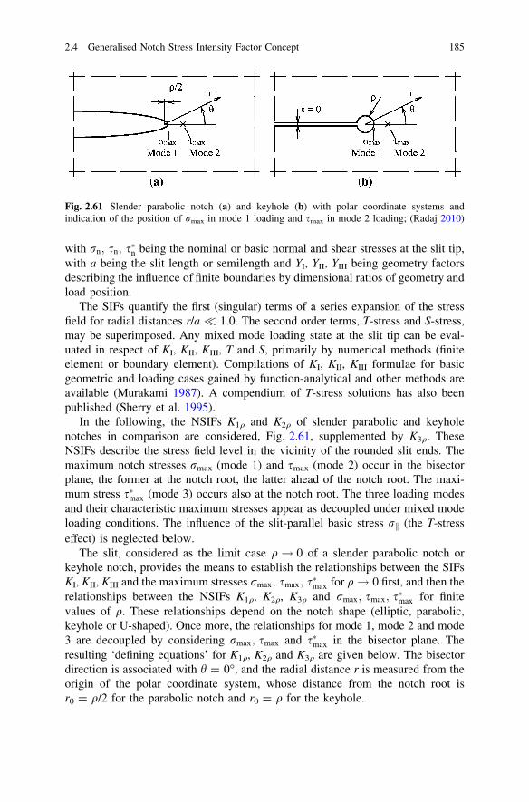
with rn; sn; s�n being the nominal or basic normal and shear stresses at the slit tip,with a being the slit length or semilength and YI, YII, YIII being geometry factorsdescribing the influence of finite boundaries by dimensional ratios of geometry andload position.
The SIFs quantify the first (singular) terms of a series expansion of the stressfield for radial distances r/a � 1.0. The second order terms, T-stress and S-stress,may be superimposed. Any mixed mode loading state at the slit tip can be eval-uated in respect of KI, KII, KIII, T and S, primarily by numerical methods (finiteelement or boundary element). Compilations of KI, KII, KIII formulae for basicgeometric and loading cases gained by function-analytical and other methods areavailable (Murakami 1987). A compendium of T-stress solutions has also beenpublished (Sherry et al. 1995).
In the following, the NSIFs K1q and K2q of slender parabolic and keyholenotches in comparison are considered, Fig. 2.61, supplemented by K3q. TheseNSIFs describe the stress field level in the vicinity of the rounded slit ends. Themaximum notch stresses rmax (mode 1) and smax (mode 2) occur in the bisectorplane, the former at the notch root, the latter ahead of the notch root. The maxi-mum stress s�max (mode 3) occurs also at the notch root. The three loading modesand their characteristic maximum stresses appear as decoupled under mixed modeloading conditions. The influence of the slit-parallel basic stress rk (the T-stresseffect) is neglected below.
The slit, considered as the limit case q! 0 of a slender parabolic notch orkeyhole notch, provides the means to establish the relationships between the SIFsKI, KII, KIII and the maximum stresses rmax; smax; s�max for q! 0 first, and then therelationships between the NSIFs K1q, K2q, K3q and rmax; smax; s�max for finitevalues of q. These relationships depend on the notch shape (elliptic, parabolic,keyhole or U-shaped). Once more, the relationships for mode 1, mode 2 and mode3 are decoupled by considering rmax; smax and s�max in the bisector plane. Theresulting ‘defining equations’ for K1q, K2q and K3q are given below. The bisectordirection is associated with h = 0�, and the radial distance r is measured from theorigin of the polar coordinate system, whose distance from the notch root isr0 = q/2 for the parabolic notch and r0 = q for the keyhole.
Fig. 2.61 Slender parabolic notch (a) and keyhole (b) with polar coordinate systems andindication of the position of rmax in mode 1 loading and smax in mode 2 loading; (Radaj 2010)
2.4 Generalised Notch Stress Intensity Factor Concept 185

Converting the limit value equations for KI, KII, KIII, Eqs. (2.127), (2.128),(2.130), to the equations for K1q, K2q, K3q (Lazzarin et al. 2009), the followingrelationships are derived for slender parabolic notches:
K1q ¼ffiffiffiffiffiffi
pqp
2rmax ðh ¼ 0; r ¼ 0:5q; T ¼ 0Þ ð2:151Þ
K2q ¼ffiffiffiffiffiffi
pqp
0:3849smax ðh ¼ 0; r ¼ 1:5qÞ ð2:152Þ
K3q ¼ffiffiffiffiffiffi
pqp
s�max ðh ¼ 0; r ¼ 0:5qÞ ð2:153Þ
The corresponding relationships for the keyhole notch in Lazzarin’s terminol-ogy are the following (Kullmer 1992; Radaj et al. 2001; Smith 2006):
K1q ¼ffiffiffiffiffiffi
pqp
2:1213rmax ðh ¼ 0; r ¼ q; T ¼ 0Þ ð2:154Þ
K2q ¼ffiffiffiffiffiffi
pqp
0:7132smax ðh ¼ 0; r ¼ 1:723qÞ ð2:155Þ
K3q ¼ffiffiffiffiffiffi
pqp
1:4142s�max ðh ¼ 0; r ¼ qÞ ð2:156Þ
Obviously, K1q, K2q and K3q are smaller for the keyhole notch than for theparabolic notch when rmax; smax or s�max have the same value but using the sameremote loading stresses results in identical NSIF values for the two notch shapes.
Some general questions arise in respect of a potential use of the NSIFs inengineering applications where structural boundaries may occur close to the con-sidered notches, e.g. when applying the reference notch concept to welded jointmodels. Analytical expressions for the NSIFs are difficult to derive in such cases.Also, compiled data are not available. Therefore, the NSIF must be determinedindividually, using the FE or boundary element method and evaluating rmax; smax ors�max for the preset notch radius q. Provided the notch shape in the model and in thederivation of the NSIF formula is identical (the normal choice), the evaluated NSIFvalue will be unambiguous and accurate. This means that the notch shape should bechosen in correspondence to the actual modelling requirements. Mostly, a keyholeor a U-shaped notch will be appropriate. In any case, the applied notch shape shouldbe specified when presenting NSIF values. Only then, these can be used to recon-struct the notch stress field from given K1q, K2q, K3q and q values on the basis of theresulting rmax; smax and s�max values. In the case of superimposed mode 1 and mode2 stress fields, the resulting rh max value at the notch edge outside the bisector planecan easily be determined. In the case of a non-zero slit-parallel basic stress rk, theappertaining notch stress field can additionally be superimposed, so that the stressfield near the rounded slit tip is completely and accurately determined.
The necessary theoretical limit conditions already mentioned, Eq. (2.138), arethe following:
186 2 Extended Stress Intensity Factor Concepts

KI ¼ limq!0
K1q ðrk ¼ 0Þ ð2:157Þ
KII ¼ limq!0
K2q ð2:158Þ
KIII ¼ limq!0
K3q ð2:159Þ
The above considerations show that the values of K1q, K2q, K3q can beapproximated by the values of KI, KII, KIII in the case of a microkeyhole or a slit-like U-shaped notch. The designation ‘micro’ means that the keyhole radius q issubstantially smaller than the structural dimensions which control the basicstresses in the slit tip area so that major cross-sectional weakening effects areavoided. Inversely, the KI and KII values may be determined by the limit valueprocedure expressed by Eqs. (2.157–2.159). This was the original usage in thehistorical development. In strength assessments by engineers, the micronotch isapplied as a means to quantify the near-field stress level. Because cross-sectionalweakening is not at all occurring, the SIFs KI, KII, KIII are better suited for strengthassessments than the NSIFs K1q, K2q, K3q.
2.4.8 The T-Stress Effect in Rounded Notch Configurations
As already stated, the SIFs, NSIFs and generalised NSIFs are comprehensiveparameters characterising not only the maximum stress at a point, but the wholestress field in the vicinity of the crack tip, notch tip or notch root. They aresupplemented by the non-singular stress field components, described by theT-stress and S-stress where appropriate, Eqs. (2.13), (2.15), (2.73). A necessarycondition on all these parameters is that they are approximately constant in theconsidered near field of the notch. This constancy has been proven by the diagramsshowing the simple or generalised NSIF values over the distance from the notch tipor notch root. Higher order stress field terms may be added in unconventionalcases such as application to thin-sheet lap joints.
In summary, there is no problem in using these parameters for defining thestress fields near pointed or sharply rounded notches as far as these can beapproximated and superimposed by the considered singular and non-singular stressfields. Substantially three-dimensional configurations must be excluded.
The situation may become complicated when determining the SIF parametersfrom FE analysis models in cases of application to specimens and structuralmembers. Here, the correct separation of the parameters is important: the sepa-ration of the mode 1 and mode 2 related constituents and the separation of theequivalent to the T-stress in rounded notch configurations.
The separation of mode 1 and mode 2 related constituents is not possible whenevaluating the out-of-bisector maximum notch stresses, whereas the separation isno problem when evaluating the in-bisector stresses rh and srh, as shown in the
2.4 Generalised Notch Stress Intensity Factor Concept 187

preceding subsections. The separation of the T-stress equivalent in rounded notchconfigurations is dealt with below, followed by a glance at the correspondingS-stress problem.
The T-stress is defined for pointed crack or slit tips (2a = 0) subjected to in-plane loading. The term ‘slit’ (comprising the crack) is preferred in the followingparagraphs of this subsection. The eigenvalue-based series expansion of the in-plane stress field at the slit tip, Eq. (2.9), is truncated in general after the secondterm. The resulting stress field equation can be split into an even and an odd part inrespect of the polar angle h, the even part connected with the parameters KI and T,the odd part with the parameter KII (Sneddon 1946; Irwin 1957). The first orderterm defines the stress singularity at the pointed slit tip (r = 0), resulting in theSIFs KI and KII. The second order term defines a uniform slit-parallel tensile orcompressive stress named ‘T-stress’ (Larsson and Carlsson 1973). These param-eters control the stress field near to the slit tip, the ‘near field’, now written with theusual nomenclature, compare Eqs. (2.10) and (2.11):
rð1;2ÞI; ij ¼KIffiffiffiffiffiffiffiffi
2prp f ð1ÞI; ij ðhÞ þ T f ð2ÞT; ijðhÞ ði, j ¼ r; hÞ ð2:160Þ
rð1;2ÞII; ij ¼KIIffiffiffiffiffiffiffiffi
2prp f ð1ÞII; ijðhÞ ði, j ¼ r; hÞ ð2:161Þ
The T-stress may be determined from analytical solutions after series expansionof the stress field. In the case of FE modelling, it is usually determined from themedium stress in the two flank sides of the slit, evaluating the midsection values incase of internal slits (Williams 1957). Also, it may result from the difference in thestresses rr and rh acting in the ligament close to the slit tip, Eq. (2.19); (Lazzarinet al. 2009).
When the pointed slit tip with occurrence of a T-stress is substituted by arounded slit notch (e.g. a keyhole), the T-stress may deteriorate the usual evalu-ation procedures for K1q. The reason is, that the K1q related notch stresses aresuperimposed by the T-stress related notch stresses. Evaluations of KI and K1q
based on the total notch stresses may thus be affected, Eqs. (2.127) and (2.129). Ifthe T-stress effect is included in K1q, the limit value relationship, Eq. (2.138), is notapplicable, because non-singular stress field components are now wrongly allottedto the singular stress parameter. It is desirable, to separate the T-stress effect inorder to ensure the correct application of the limit value relationship (Radaj 2010).
A problem of language is first addressed. Just as KI and KII do not occur atrounded slit tips, the same is true for the T-stress. The in-bisector slit-parallel stressrr(r, 0) representing the T-stress at the pointed slit tip, is decreasing to zero at therounded slit tip. So, the T-stress in a rounded slit tip model is always that slit-parallel stress which would occur without slit tip rounding in the midsection of therelevant internal slit model. This T-stress can be used to approximate the T-stressrelated notch stresses. The accuracy of the solution will be all the better, the smallerthe notch radius in relation to the characteristic dimensions of the problem is.
188 2 Extended Stress Intensity Factor Concepts

The reference model of the slit is the already considered keyhole or slenderelliptical notch subjected to tensile loading in slit-parallel direction. The notchstresses at the keyhole under a uniform slit-parallel tensile or compressive stress rkare given by (Radaj et al. 2001):
rh ¼ rk 1� 2 cos 2hð Þ ð2:162Þ
The solution is identical with Kirsch’s solution for a single hole, with rh max
= 3rk at h = 90� and rh min = -rk at h = 0� (Kirsch 1898). A more accuratesolution for the keyhole gives rh max = 3.06rk and rh min = -rk. The U-shapednotch results in rh max = 2rk at h = 69� (Radaj and Schilberth 1977, ibid. Fig. 5,r/b = 1, r/a = 0.01), whereas rh min remains unchanged. Considering the elliptical(or parabolic) slender notch, no pronounced stress maximum occurs at the notchedge, whereas rh min = -rk at h = 0�. The latter value is confirmed by Neuber’sformulae for uniaxial and biaxial tensile loading in comparison (Neuber 1985).One application-relevant conclusion from the above is that the value of the originalT-stress is expressed by the notch stress at h = 0� with opposite sign. This has tobe taken into account when evaluating the K1q parameter from FE models usingthe notch stress at h = 0�.
Before doing so, the difference between the T-stresses at mode 1 loaded internaland external slits is demonstrated. At external slits (with an unloaded externalboundary), no T-stress occurs whereas at internal slits it generally does. In order toclarify the situation in the latter case, the slit-parallel and slit-normal stresses rx
and ry in the slit and ligament line y = 0 is discussed based on Westergaard’s
Fig. 2.62 Infinite plate with internal slit subjected to uniaxial (a) and biaxial (b) tension load;remote tensile stress r; stresses rx, ry and T in ligament and slit line; (Radaj 2010)
2.4 Generalised Notch Stress Intensity Factor Concept 189

closed-form solution, Fig. 2.62 (Westergaard 1939; Hahn 1976). The infinite plate,subjected to uniaxial or biaxial remote tensile stress r is considered.
The solution for uniaxial tension gives:
rx ¼�r
rx=ffiffiffiffiffiffiffiffiffiffiffiffiffiffiffi
x2 � a2p
� rry ¼
�
0
rx=ffiffiffiffiffiffiffiffiffiffiffiffiffiffiffi
x2 � a2p
� ðx\aÞðx[aÞ
ð2:163Þ
The solution for biaxial tension gives:
rx ¼ ry ¼0
rx=ffiffiffiffiffiffiffiffiffiffiffiffiffiffiffi
x2 � a2p
� ðx\aÞðx [ aÞ
ð2:164Þ
The T-stress can be determined from the difference in the stresses rx and ry onthe ligament close to the slit tip (Lazzarin et al. 2009). The expression for theT-stress is reformulated here as a limit value using the stress components rx and ry
instead of rr and rh:
T ¼ limx!aðrx � ryÞ ðx [ aÞ ð2:165Þ
Considering the above mentioned Westergaard solution, one gets T = -r inuniaxial tension and T = 0 in biaxial tension. Comparing this result with the plotsin the figure, it is obvious that the T-stress in the two loading cases can beidentified from the slit-parallel stress rx in the midsection of the internal slit, butnot from the remote stress at the outside boundary of the plate. On the other hand,any superimposed loading rx? at infinity will directly change the T-stress byT = rx?. Then, the T-stress consists of two parts, the one component connectedwith r = ry?, the other with rx?. When considering external notches, thesecorrespond to the condition rx? = 0, in general, for example the keyhole notchsolution (Kullmer 1992; Radaj et al. 2001). Therefore, the solution for uniformslit-parallel tension loading is separately given by the latter authors. Altogether,it is concluded that, under uniaxial tension loading of internal rounded slit tips, theslit-parallel basic stress rk is equal in size and opposite in sign to the remote slit-transverse tensile stress, provided the notch radius is small in relation to the outerdimensions of the structural member.
Evaluating K1q in cases of rk= 0 from FE analysis results, it is necessary todetermine K�1q without the T-stress effect and to register the T-stress or the corre-sponding slit-parallel basic stress rk separately, because different stress fields areconnected with the two parameters. The equations corresponding to Eqs. (2.151)and (2.154) for the parabolic and keyhole notch types, respectively, then read asfollows:
K�1q ¼ffiffiffiffiffiffi
pqp
2ðrmax þ rkÞ ðh ¼ 0; r ¼ 0:5qÞ ð2:166Þ
K�1q ¼ffiffiffiffiffiffi
pqp
2:1213ðrmax þ rkÞ ðh ¼ 0; r ¼ qÞ ð2:167Þ
190 2 Extended Stress Intensity Factor Concepts

Fig. 2.63 Symmetry quarterof rectangular plate with two-sided keyhole slit, subjectedto tensile loading byprescribed displacement v0
(a) and to in-plane shearloading by prescribeddisplacements u0 and v0
(b) of the external boundary;(Radaj et al. 2009)
The necessary limit value of Eq. (2.157) is substituted as follows:
K1 ¼ limq!0
K�1q ð2:168Þ
Considering K�1q with q! 0 as indicated by Eq. (2.168), the slit-parallel stressrk in Eqs. (2.166) and (2.167) can be substituted by T. Therefore, the designation‘T-stress-corrected NSIF K�1q’ is introduced. In cases of rounded slit tips, thiscorrection is an approximation.
As an example for the T-stress correction, the plots of the KI, K1q and KII, K2q
values for the two-sided keyhole slit in a rectangular plate with outer dimensionssubstantially larger than the notch radius, Fig. 2.63, has been reconsidered (Radaj2010). The plate is subjected to uniaxial tensile and pure shear loading by prescribedremote boundary displacements with a reference stress of r0 = 100 MPa ands0 = 100 MPa, respectively (Lazzarin et al. 2009). The K1q and K2q values wereevaluated from FE models using Eqs. (2.154) and (2.155) not only at r = q orr = 1.723q, but also at other distances (r - q) close to the slit tip without consid-ering the T-stress effect. The KI and KII values were also evaluated from FE models.Actually, the T-stress was found to be T = -60 MPa. Therefore, the K1q values areexactly 1.09 % too large at (r - q) = 0.001 mm, upper graph of Fig. 2.64. Thedifference decreases for (r - q) [ 0.001 mm. The well known maximum notchstress gradient -2/q perpendicular to the hole edge results in a full cancellation ofthe enlargement at (r - q) = q/2 = 0.025 mm. Obviously, the T-stress correctedK�1q curve is then identical with the KI curve within the plotting accuracy. The limitcondition of Eq. (2.168) is precisely met, which means that the hole is sufficientlysmall to possess the same geometry factor YI as the pointed slit tip, or, in other words,that the cross-sectional weakening by the hole is negligibly small.
2.4 Generalised Notch Stress Intensity Factor Concept 191

The deviations between the K2q and KII curves in the lower graph of Fig. 2.64have another reason. They occur for distances smaller than the smax position at(r - q) = 0.723q = 0.0362 mm. They mirror the fact that the correct K2q value isdetermined from smax at the above distance from the notch edge, with no con-vergence for evaluations at distances closer to the notch edge. The necessaryconvergence condition is K2q ! KII for q! 0, but not for ðr � qÞ ! 0. Thedeviations are not a T-stress effect, because the evaluated shear stresses areindependent of any T-stress.
Another, more convincing proof of the necessity to apply the T-stress correctionhas been given by re-analysing Lazzarin’s tensile-shear loaded lap joint model(Radaj 2010).
The second order term in mode 1 loading which constitutes the T-stress at slittips may also occur with V-notches (Ayatollahi and Dehghany 2010; Ayatollahiand Nejati 2011). An effect on K1q similar to the T-stress effect above can beexpected, but has not yet been investigated. The second order term in mode 3loading which has been named S-stress, does not affect the limit value K3q ! KIII
because it does not contribute to the shear stresses shz(r, 0) in the bisector planewhich are related to K3q.
Fig. 2.64 Generalised NSIFs K1q, K�1q; K2q in comparison to SIFs KI, KII, evaluated alongbisector or ligament dependent on distance from notch root or slit tip, FE model of rectangularplate with two-sided keyhole or slit subjected to tensile and in-plane shear loading; (Lazzarinet al. 2009)
192 2 Extended Stress Intensity Factor Concepts

2.4.9 Application of the Generalised NSIF Concept to RoundBars with Shoulder Fillet
The generalised NSIF concept allows to describe the stress field at rounded not-ches, especially at sharply rounded notches, by a single parameter per loadingmode. The intensity of the stress field, for which the NSIF is determined, must beavailable from other sources, in engineering applications from a FE analysis of theconsidered notch configuration.
The NSIFs thus found do not allow to perform a strength assessment directly.On the other hand, incorporation of the FE analysis results into the analyticalframe of the NSIF concept allows fundamental insights in the setting of the modeland its behaviour under modified conditions. This may be illustrated by the fol-lowing example (Zappalorto and Lazzarin 2011(3)).
A round bar with shoulder fillet subjected to torsional loading is considered,Fig. 2.65. The shoulder fillet is approximated by a hyperbolic notch with notchopening angle 2a = 90�, inclined by b = 45� against the bar axis. The notchradius is q = 0.25 or 1.0 mm. The radius up to the gross cross-section amounts toRg = 54.5 or 25.5 mm, the radius up to the notch root thus being Rn = 50 or20 mm.
The notch stress field (out-of-plane shear) is separated into two parts, one partantimetric, the other part symmetric, Eq. (2.122). Engineers are not always awareof the symmetric part, which corresponds to the S-stress originally defined at slittips (2a = 0�). The two parts are controlled by the antimetric and symmetric
NSIFs, KðaÞ3q and KðsÞ3q . They are determined according to Eqs. (2.124) and (2.125)and are related to the nominal torsional stress sn,g in the gross cross-section,
Fig. 2.65 Round bar with hyperbolic shoulder fillet subjected to torsional loading; (Zappalortoand Lazzarin 2011(3))
2.4 Generalised Notch Stress Intensity Factor Concept 193

Fig. 2.66 Generalised NSIFs KðaÞ3q and KðsÞ3q of torsional-loaded round bar with hyperbolicshoulder fillet (2a = 90�, two notch radii q) dependent on distance from notch root; evaluation ofFE analysis results; nominal stress sn,g in gross cross-section; (Zappalorto and Lazzarin 2011(3))
Fig. 2.67 Stress shz in notch bisection over distance form notch root; torsional-loaded round barwith hyperbolic shoulder fillet; original compared with K3q-based FE analysis results; nominalstress sn,g in gross cross-section; (Zappalorto and Lazzarin 2011(3))
194 2 Extended Stress Intensity Factor Concepts

Fig. 2.66. Obviously, the notch radius q B 1 mm has no major influence on the
NSIFs. The values of KðaÞ3q and KðsÞ3q should not directly be set into comparison,
because they are different in their dimension. The NSIF KðaÞ3q defines a stress field
which is singular for q! 0, whereas KðsÞ3q is associated with non-singular stressesunder the limit condition.
The out-of-plane shear stresses shz/sn,g in the bisector plane are plotted over thedistance from the notch root for q = 0.25 and 1.0 mm, Fig. 2.67. FE analysisresults and K3q-based analytical curves are compared. There is no conceivabledifference up to 10 mm ahead of the notch root with Rg = 54.5 mm. ForRg = 24.5 mm, this range is reduced to 1.0 mm. The stresses shz, srz and svz at the(hyperbolic) notch edge are plotted over the polar angle h, Fig. 2.68. The shearstress svz acts in planes normal to the notch edge, whereas the shear stresses shz andsrz are related to the planes in the r–h system before being converted to the
u–v system. The curve of svz deviates from the antimetric part sðaÞvz of the analyticsolution outside the bisector plane. Rather confusing but correctly, the antimetricshear stresses in the r–h system appear as symmetric in the u–v system followingthe notch edge in the positive direction of v.
In the same investigation, also the torsional loaded round bar with an inclinedparabolic notch is considered. Further solutions are available for U-notches andblunt V-notches with an accurate mapping of the circular notch edge (Lazzarinet al. 2007). In both cases, the NSIFs are not defined.
Fig. 2.68 Stresses shz, srz, svz and sðaÞvz at notch edge over polar angle h; torsional-loaded roundbar with hyperbolic shoulder fillet; original compared with K3q-based FE analysis results;nominal stress sn,g in gross cross-section; (Zappalorto and Lazzarin 2011(3))
2.4 Generalised Notch Stress Intensity Factor Concept 195

2.4.10 Fatigue Limit Expressed by Notch Stress IntensityFactors
The generalised NSIF approach is closely related to the simple NSIF approach inrespect of fatigue assessment. Both approaches can be used to assess the crackinitiation life of notched members inclusive of fillet-welded joints (Boukharoubaet al. 1995; Verreman and Nie 1996, 1997). The fatigue assessment of notchedmembers comprises first the determination of the high-cycle fatigue limit (e.g. thetechnical endurance limit), second the extension of this limit value to the medium-cycle and low-cycle fatigue range (e.g. via the notch stress or strain S–N curve) andthird the formulation of the multiaxial failure criterion (e.g. the von Mises equivalentstress in ductile materials). The fatigue process is understood as crack nucleation,short-crack growth and long-crack propagation. Crack nucleation is induced byrepeated plastic notch tip deformation. Short cracks initiated at sharp notches may bearrested, provided the notch stress gradient is sufficiently steep and the basic stresslevel sufficiently low (non-propagating short cracks). The high-cycle fatigue limitmay be described on the basis of elastic material behaviour.
The high-cycle fatigue limit for notched members has been mainly consideredin relation to the fatigue limit of the unnotched material. This is expressed by thefatigue notch factor Kf which turns out to be smaller than the elastic notch stressconcentration factor Kt. The relation between the fatigue strengths of roundedcompared with pointed notches (inclusive of cracks) has only exceptionally beeninvestigated. Stress intensity factors are basic for such investigations. They allowan assessment without a detailed short-crack propagation analysis, which may betoo complicated for engineering purposes. Instead, the stress field in the damagingzone near the notch tip or notch root characterised by the simple or generalisedNSIFs is evaluated. This ‘near field’ produces the driving force for crack initiationand propagation. Widely used are average stress criteria (notch stresses averagedover a material-characteristic microstructural length, area or volume at the notchtip or notch root) or, alternatively, critical distance criteria (notch stress at amaterial-characteristic microstructural distance from the notch tip).
The basic idea behind the approach presented in the following is the consid-eration of two different fatigue limits in the case of sharp notches (the notch tipradius is zero or very small, the notch stress concentration factor is correspond-ingly high). One fatigue limit is related to the nucleation of cracks that do notpropagate, governed by the stress concentration factor Kt. The other fatigue limit isrelated to cracks that nucleate and then propagate, the threshold stress intensityfactor DKth applied to crack length plus notch depth being relevant.
It is straightforward with regard to the crack propagation fatigue limit of not-ches to introduce a crack-propagation-relevant microstructural length derived fromthe threshold stress intensity factor DKth of long cracks and from the relevant crackpropagation fatigue limit Drth. Such a length parameter a0 has been defined in thefollowing form (El Haddad et al. 1979):
196 2 Extended Stress Intensity Factor Concepts
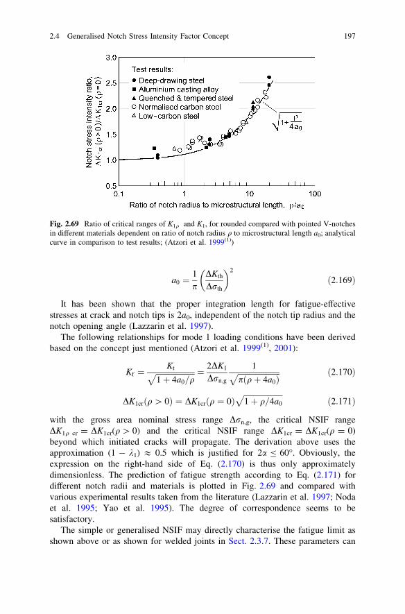
a0 ¼1p
DKth
Drth
� �2
ð2:169Þ
It has been shown that the proper integration length for fatigue-effectivestresses at crack and notch tips is 2a0, independent of the notch tip radius and thenotch opening angle (Lazzarin et al. 1997).
The following relationships for mode 1 loading conditions have been derivedbased on the concept just mentioned (Atzori et al. 1999(1), 2001):
Kf ¼Kt
ffiffiffiffiffiffiffiffiffiffiffiffiffiffiffiffiffiffiffiffi
1þ 4a0=qp ¼ 2DK1
Drn;g
1ffiffiffiffiffiffiffiffiffiffiffiffiffiffiffiffiffiffiffiffiffiffi
pðqþ 4a0Þp ð2:170Þ
DK1crðq [ 0Þ ¼ DK1crðq ¼ 0Þffiffiffiffiffiffiffiffiffiffiffiffiffiffiffiffiffiffiffiffi
1þ q=4a0
p
ð2:171Þ
with the gross area nominal stress range Drn,g, the critical NSIF rangeDK1q cr = DK1cr(q[ 0) and the critical NSIF range DK1cr = DK1cr(q = 0)beyond which initiated cracks will propagate. The derivation above uses theapproximation (1 - k1) & 0.5 which is justified for 2a B 60�. Obviously, theexpression on the right-hand side of Eq. (2.170) is thus only approximatelydimensionless. The prediction of fatigue strength according to Eq. (2.171) fordifferent notch radii and materials is plotted in Fig. 2.69 and compared withvarious experimental results taken from the literature (Lazzarin et al. 1997; Nodaet al. 1995; Yao et al. 1995). The degree of correspondence seems to besatisfactory.
The simple or generalised NSIF may directly characterise the fatigue limit asshown above or as shown for welded joints in Sect. 2.3.7. These parameters can
Fig. 2.69 Ratio of critical ranges of K1q and K1, for rounded compared with pointed V-notchesin different materials dependent on ratio of notch radius q to microstructural length a0; analyticalcurve in comparison to test results; (Atzori et al. 1999(1))
2.4 Generalised Notch Stress Intensity Factor Concept 197

also indirectly be relevant for fatigue as can be seen from the J-integral criterion(see Sect. 2.3.8) or from the local strain energy density criterion (see Sect. 3.2.3).
Proceeding from the high-cycle fatigue limit, especially at the branching pointbetween the crack nucleation and crack propagation curves in Frost’s endurancelimit over SCF diagram, rnE = f(Kt), the medium-cycle S–N curve can beempirically approximated using an inverse slope exponent k which depends on theamount of elastic-plastic notch support during crack initiation and subsequentcrack propagation. A more rational approach consists in using crack initiationcriteria based on elastic or plastic NSIFs in the medium-cycle and low-cyclefatigue range, respectively, allowing extensions into the crack propagation range.
Multiaxial failure criteria are needed for the fatigue assessment under mixedmode loading conditions. These can be based on superposition of the effects of theindividual loading modes as far as elastic NSIFs are applicable. An elliptical curverelationship has been used for fillet-welded joints in analogy to the Gough ellipse(see Sect. 2.3.6).
2.4.11 Conclusions
The stress distribution at sharply rounded notches can be described by the loadingmode related generalised NSIFs K1q, K2q, K3q as the governing field parameters.These NSIFs are linked not only to the maximum notch stresses rmax, smax, s�max,which constitute the conventional SCFs in engineering science, but to the wholenotch stress field. The field information is needed for assessing failure processessuch as crack initiation and propagation or microstructural damaging phenomena.The size effect on the endurable nominal stresses is already included in theendurable NSIFs.
The generalised NSIFs can also be applied to notches with a substantiallyincreased notch radius, provided a proper evaluation over some distance from thenotch root in the bisector plane is performed, proving a sufficiently constant valueof the NSIF. This value may depend on the notch radius. A substantial increasewith the notch radius may be observed, especially under mode 2 loading condi-tions where the maximum notch stress occurs outside the bisector plane. Thegeneralised NSIFs and the appertaining stress equations depend on the notch shape(parabolic, hyperbolic, elliptical, blunt V-notch, V-notch with circular root arc orV-notch with root hole) and on the applied analytical frame. The internal orexternal setting of the notch may include a minor influence of loading in thebisector direction. Structural boundary, loading and support conditions have aninfluence, especially if they act close to the notch. Only the effect of a finite notchdepth relative to the notch radius has been systematically investigated to someextent.
The numerical basis of generalised NSIF evaluations in configurations withfinite boundaries is the FE analysis method, performed with sufficiently fine
198 2 Extended Stress Intensity Factor Concepts

meshes. The theoretical frame of the NSIFs allows interpretations and generali-sations of the FE analysis results.
Fatigue assessments are possible on the basis of the generalised NSIFs, but thisaccess has not yet been elaborated. One reason may be, that the NSIFs depend onthe overall notch shape, on the geometrical details at the notch root and on theapplied analytical frame. So, their generality is restricted. As far as the stressdistribution of the sharply rounded notch expressed by the generalised NSIFremains close to that of the pointed notch, expressed by the simple NSIF, failurecriteria and data are transferable to some extent.
2.5 Plastic Notch Stress Intensity Factor Concept
2.5.1 Survey of Section Contents
The preceding sections refer to the stress fields and NSIFs of pointed and roundednotches under the condition of linear-elastic material behaviour. Now, the pre-sentations are extended to nonlinear-elastic and thus approximated elastic-plasticmaterial behaviour. The stress singularity at pointed notches continues to exist,provided strain hardening is taken into account. Plastic NSIFs are defined asdistinguished from the elastic NSIFs. They include plastic strain intensity factors,which exist also for a non-hardening material behaviour.
Plastic stress intensity factors were first proposed for cracked plates undernonlinear conditions of material behaviour (Hilton and Hutchinson 1971; Hilton1973) and later on extended to pointed V-notches with arbitrary notch openingangle (Lazzarin et al. 2001). Plastic NSIFs can be stated in terms of the elasticNSIFs, provided the local elastic and elastic-plastic strain energy densities aver-aged over a circle sector volume around the pointed V-notch are set equal, which isappropriate under small scale yielding conditions (Lazzarin and Zambardi 2002).
Basic information is given on the deformation theory of plasticity which leadsto the HRR elastic-plastic stress and strain fields at the notch tip, named afterHutchinson, Rice and Rosengren. The elastic-plastic fields at V-notches subjectedto tensile loading inclusive of the definition of the plastic NSIF are presented. Thecorresponding fields in out-of-plane shear loading are easier to describe analyti-cally. The parabolic notch is treated first, followed by V-notches in general.A uniform analytical frame based on the Neuber nonlinear material law is pre-sented. The Neuber rule linking the maximum elastic-plastic stresses and strains atrounded notch tips and Glinka’s alternative concept are contrasted with findings byZappalorto and Lazzarin, who identified an influence of the notch opening angleand of the hardening exponent on the Neuber rule. A final subsection is devoted tothe analytical description of the elastic-plastic material laws.
When reviewing the available publications on the plastic NSIF concept, a lackof conceptual clarity in respect of the yield limit parameters has to be overcome in
2.4 Generalised Notch Stress Intensity Factor Concept 199
some cases. As explained in more detail in Sect. 2.5.10, the real (engineering)yield limit parameters eY, rY or cY, sY (marked or offset yield limit) are notidentical with the substitute (analytical) yield limit parameters e0, r0 or c0, s0
resulting from the intersection point of the linear-elastic and the asymptotic plasticlimit curves. On the other hand, there is no general relationship available forrelating the two types of yield parameters. The real yield limit is sometimesintroduced in comparative investigations based on the FE method, when using theRamberg–Osgood material law. It was not possible to remove any possible con-fusion in the following. The choice of the original authors had to be respected.
The expositions are mainly based on the analytical development of the plasticNSIF concept by Lazzarin and Zappalorto in a set of excellent publications whichcan be found in the list of references at the end of Chap. 2. A list of symbols is alsoavailable there.
2.5.2 Deformation Theory of Plasticity Founding the HRR Fields
When loading of the material exceeds a certain level, plastic deformation (yield-ing) occurs immediately (i.e. independently of time). The usual assumption is, thatthe elastic and plastic strains or strain increments add up to their total values:
eij ¼ eij; e þ eij;p; deij ¼ deij; e þ deij; p ð2:172Þ
The elastic strains are connected with the stresses according to Hooke’s law.The plastic strains are conforming to the multiaxial yield condition, mostlyaccording to von Mises. Two different formulations of the relationships betweenplastic strains and (elastic) stresses are in use. The ‘incremental theory’ refers toplastic strain increments in relation to the analytical yield surface. It is not used inthe following. The ‘deformation theory’ founding the HRR fields considers thetotal strains. Both theories assume in general that no plastic volume change occurs,ep,kk = 0.
In the deformation theory leading to the HRR fields described below, a hard-ening material is considered whose uniaxial stress–strain curve is represented bythe Ramberg–Osgood material law in the following normalised form related to e0,r0 which deviates from the original form related to E and H, Eq. (2.264) (Grossand Seelig 2001), Fig. 2.70a:
ee0¼ r
r0þ a
rr0
� �n
ð1\n\1Þ ð2:173Þ
where the terms on the right-hand side of the equation denote the elastic andplastic strain ratios. The quantities e0, r0 refer to the initiation of yielding,e0 & eY, r0 & rY, provided the factor a is sufficiently small. Under this specialcondition, the factor a results approximately from rn�1
Y E=Hn with the yield limitrY = EeY, the modulus of elasticity E and the hardening (or strength) coefficient
200 2 Extended Stress Intensity Factor Concepts

H (where H is equal to r at ep = 1). The ‘strain hardening exponent’ n is limitedby n = 1 for linear-elastic and n!1 for elastic-perfectly-plastic behaviour. Ithas to be noted that many authors prefer the reciprocal value 1/n instead of n.
At pointed notch tips, the plastic strains are found to be singular, so that thenon-singular elastic strains are negligible in relation to the plastic strains, and Eq.(2.173) can be reduced to the total strain power law, in which the originally plasticstrains are now interpreted as total strains:
ee0¼ a
rr0
� �n
ð2:174Þ
The total strain power law, Eq. (2.174), when generalised to multiaxial stressstates based on the invariant J2 of the deviatoric stress state, can be written asfollows:
eij
e0¼ 3a
2re
r0
� �n�1 sij
r0; re ¼
ffiffiffiffiffiffiffiffiffiffiffiffi
32
sijsij
r
ð2:175Þ
with the effective stress re according to the von Mises criterion and the deviatoricstress component sij.
The material law, Eq. (2.175), is also considered valid for a stress–strainrelationship consisting of a linear-elastic rise up to the intersection point e0, r0
followed by the total strain power law in the plastic range, Fig. 2.70b:
ee0¼ r
r0ðe e0Þ
ee0¼ r
r0
� �n
ðe e0Þð2:176Þ
Obviously, a = 1.0 when comparing Eq. (2.173), i.e. a is not small so that theapproximations e0 & eY and r0 & rY are not anymore valid. In the following, the
Fig. 2.70 Uniaxial stress–strain curves according to the Ramberg–Osgood material law (a) andaccording to a combination of linear-elastic and total strain power law (b); different factors a inthe two graphs; (Gross and Seelig 2001)
2.5 Plastic Notch Stress Intensity Factor Concept 201

quantities e0, r0 are termed ‘substitute yield limit’ in order to distinguish themfrom the real yield limit eY, rY.
In the deformation theory, the plastic material behaviour is specified as non-linear-elastic. For nonlinear-elastic solid bodies with a crack undergoing mono-tonic, small-strain deformation, Hutchinson, Rice and Rosengren have shown thatthe intensity of the near-tip field is expressed by the J-integral and that the stresses,strains and displacements exhibit a singularity described by r-1/(n+1), r-n/(n+1) andr-1/(n+1), respectively (Hutchinson 1968; Rice and Rosengren 1968). These ‘HRRfields’ close to the crack tip are written as follows:
rij ¼ r0J
ar0e0I r
� �1=ðnþ1Þ~rijðh; nÞ ð2:177Þ
eij ¼ ae0J
ar0e0I r
� �n=ðnþ1Þ~eijðh; nÞ ð2:178Þ
ui ¼ ae0rJ
ar0e0I r
� �n=ðnþ1Þ~uiðh; nÞ ð2:179Þ
with the ‘universal functions’ ~rijðh; nÞ; ~eijðh; nÞ and ~uiðh; nÞ dependent on thepolar angle h, the strain hardening exponent n and the state of stress (plane stressor plane strain), with the J-integral and with the Integral I depending mildly onn. Deviations occur with large-scale yielding under plane strain conditions, whichmay be expressed by a ‘constraint factor’ (Shlyannikov et al. 2011).
In the equations above, the J-integral does not separate the mode 1 and mode 2loading components. Evaluated HRR-fields refer to pure mode 1 loading in gen-eral. Such evaluations show, that the HRR-dominated region at the crack tip issubstantially reduced with increasing values of n. Simultaneously, the deformedcrack tip gets more and more blunted.
Even in the considered case of crack tips (2a = 0), it has not been possible tofind a complete numerical solution. Only modelling the material as perfectly-plastic has allowed substantial progress (Unger 2001, 2005, 2007). Moving to themore general case of pointed V-notches in strain-hardening materials, the problembecomes much more demanding. Not only the ‘universal functions’ requirenumerical solution techniques, but also the exponent s characterising the degree ofthe singularity. Nonlinear differential equations and nonlinear eigenvalue problemshave to be solved, and the superposition principle, facilitating solutions in thelinear range, is not anymore applicable.
2.5.3 Elastic-Plastic Fields at Tensile Loaded V-Notches
A partial solution of the problem of elastic-plastic stress and strain fields at tensileloaded V-notches is available, originally referring to large-angle V-notches
202 2 Extended Stress Intensity Factor Concepts

simulating weld-like geometries (Lazzarin et al. 2001) and later on to pointedV-notches in general (Filippi et al. 2002(1)). Lazzarin proposed plastic notch stressintensity factors as parameters which combine the effects of member size, nominalstress level and constitutive material law on the notch stress and strain fields atpointed V-notches. Considering weld-like pointed corner notches subjected to acombination of mode 1 and mode 2 loading in the bisector plane, the notch stressesin the HRR field follow a series expansion:
rijðr; hÞ ¼ K1pr�s~rð1Þij ðhÞ þ K2pr�z~rð2Þij ðhÞ þ . . . ð2:180Þ
where K1p and K2p are the plastic notch stress intensity factors in mode 1 and mode2 loading, representing the symmetric singular stress field (first term) and theantimetric non-singular stress field (second term) for 2a[ 102�. This equationdoes not express the superposition principle, because K1p and K2p are assumed as
interconnected. Their unambiguous definition requires ~rð1Þe; max ¼ ~rð2Þe; max (absolutevalues), appertaining to the effective (or equivalent) stress re according to vonMises.
The plastic NSIF K1p is defined in analogy to the elastic NSIF K1 as follows:
K1p ¼ limr!0
ffiffiffiffiffiffi
2pp
rsrhðr; 0Þ ð2:181Þ
with the exponent s depending on the hardening exponent and the notch openingangle, Eq. (2.187).
The plastic NSIFs K1p and K2p depend on the notch opening angle 2a, thenominal stress rn, the plate thickness t, the reference stress r0 and the hardeningexponent n. The third material parameter in the Ramberg–Osgood law (besidesE and n), the hardening (or strength) coefficient H, is dependent on r0, e0.
The FE analysis for K1p of a weld-like corner notch model, 2a = 120�,t = 20 mm and n = 4.0, using the Ramberg–Osgood law, is presented inFig. 2.71. The linearised approximation of K1p in the range rn = 100–500 MPahas the following general form:
K1p ¼ ðk1rn þ k10r0Þts ð2:182Þ
Actually, the K1p curves are nonlinear and start from the origin of the diagram.This relationship is found tentatively based on the analytical assumption for K1p.Deviations of the analytical HRR solution (power law) from the FE solution(Ramberg–Osgood law) are not explicitly visible.
The result of the nonlinear eigenvalue analysis in respect of the exponent s isplotted in Fig. 2.72. The dependency on 2a is weak for not too large angles 2a, butthe dependency on n is generally strong. The exponent z in Eq. (2.180) is negativein the considered range of large values of 2a, which means, that no singularityoccurs. An example for the universal function ~rijðhÞ is given in Fig. 2.73, withexact values and approximations in comparison.
2.5 Plastic Notch Stress Intensity Factor Concept 203

A more concise derivation and definition of the plastic NSIF under mode 1loading conditions is possible based on the equivalent strain energy densityapproach (Lazzarin and Zambardi 2002). In this approach, the elastic-plastic strainenergy density at the notch tip is found coincident with that determined underlinear-elastic conditions (Glinka and Molski 1981). The approach is not directlyapplicable to pointed V-notches, since the strain energy density at the notch tip
Fig. 2.72 Exponent s of the nonlinear-elastic V-notch subjected to mode 1 (symmetric) loading;exact values (Runge-Kutta) and approximations; (Filippi et al. 2002(1))
Fig. 2.71 Weld-like corner notch: plastic stress intensity factor K1p dependent on nominal stressrn,g with material parameters n, H, r0; linearised approximation in the range rn,g = 100 to500 MPa; plate thickness t = 20 mm (Lazzarin et al. 2001)
204 2 Extended Stress Intensity Factor Concepts

tends toward infinity both for the linear-elastic and the power law hardeningmaterial. But a reformulation is possible, when applying elastic and plastic NSIFsto a finite size circle sector around the notch tip. The hypothesis is introduced that,under plane strain conditions, the value of the energy concentration due to thenotch is equal for the two material laws. Under small-scale yielding conditions,this results in an identical value of the strain energy averaged over the consideredcircle sector. As a consequence, the plastic NSIFs of pointed V-notches can bepredicted on the basis of the linear-elastic NSIFs. The essential steps of the der-ivation by Lazzarin and Zambardi are reviewed below.
The Ramberg–Osgood material law is the basis in the following form, gener-alised for multiaxial stress conditions according to the von Mises criterion:
eij ¼1þ m
Esij þ
1� 2mE
rhdij þ32rn�1
e
Cnsij ð2:183Þ
where sij is the deviatoric stress tensor, rh is the hydrostatic stress, dij the Kro-necker delta and re the von Mises equivalent stress. Actually, the asymptoticapproximation by the total strain power law is used in the analytic derivations. Thematerial characteristic constants are the hardening exponent n and the hardeningcoefficient C (better known as K or H). The multiaxiality condition (plane stress orplane strain) comes in via the equivalent stress re.
Based on Eq. (2.183), the plastic component Wp of the strain energy density canbe calculated for monotonic loading:
Wp ¼n
ðnþ 1ÞCnrnþ1
e ð2:184Þ
Fig. 2.73 Universal functions ~rijðhÞ for 2a = 90� and n = 4, mode 1 (symmetric) loading; exactvalues (Runge-Kutta) and approximations; (Filippi et al. 2002(1))
2.5 Plastic Notch Stress Intensity Factor Concept 205

The first term of the elastic-plastic stress series expansion in the close neigh-bourhood of a pointed V-notch under mode 1 loading conditions, compare Eq.(2.180), turns out to be:
rijðr; hÞ ¼ K1p r�s~rijðhÞ; reðr; hÞ ¼ K1pr�s~reðhÞ ð2:185Þ
where K1p is the plastic NSIF quantifying the intensity of the local stress field. Thedetermination of the universal functions ~rij and ~re requires a numerical solution.They are normalised in the same manner by setting the maximum value of ~reðhÞover the considered domain to unity.
Inserting Eq. (2.185) into Eq. (2.184), the elastic-plastic strain energy densityclose to the notch tip is given by:
Wpðr; hÞ ¼ n
ðnþ 1ÞCnðK1pÞnþ1r�sðnþ1Þ~reðhÞnþ1 ð2:186Þ
In the plastic zone very close to the notch tip (small-scale yielding), the elasticcontribution to the total strain energy is very small. Therefore, the total energydensity W can be set equal to the elastic-plastic energy density Wp which, on theother hand, is equal to the original linear-elastic energy density We. This shouldapply to any value of r within the considered notch tip region. Therefore, com-paring the linear-elastic and elastic-plastic singularities, an expression for theexponent s can be gained:
Weðr; hÞ / r2ðk1�1Þ; Wpðr; hÞ / r�sðnþ1Þ; s ¼ 2ð1� k1Þnþ 1
ð2:187Þ
The expression for s(k1, n) has also been derived by other authors (Kuang andXu 1987; Chen and Ushijima 2000). It is independent of the applied load value.For the crack, k1 = 0.5 and therefore s = 1/(n ? 1) are valid.
The equivalent strain energy density approach (Glinka and Molski 1981) isbased on the well-founded hypothesis that different constitutive models (elastic-plastic compared with linear-elastic) affect the relationship between stresses andstrains but leave the value of the averaged energy density at the notch tip (sectorradius R) compared with the same in the nominal stress region (energy concen-tration factors KW,p and KW,e) unchanged:
KW; p Rð Þ ¼ KW; e Rð Þ ð2:188Þ
This allows to express the plastic by the elastic stress intensity factor which caneasily be determined by FE analysis:
K1p ¼nþ 1
n
IeðcÞIpðc; nÞK
21e
Cn
2Eþ n
nþ 1rn�1
n
� �� �1=ðnþ1Þðc ¼ p� aÞ ð2:189Þ
where Ie(c) and Ip(c) are integrals of the elastic and plastic universal functions, thefirst evaluated analytically, the second numerically. The sector radius R should be
206 2 Extended Stress Intensity Factor Concepts

within the range of validity of the asymptotic one-term expansion of the notch tipstress field.
Under conditions of local yielding, the second term in the parenthesis is sub-stantially smaller than the first term, so that the following simplified formula isapplicable:
K1p ¼ AK2=ðnþ1Þ1e ð2:190Þ
A ¼ nþ 1n
Cn
2E
IeðcÞIpðc; nÞ
� �1=ðnþ1Þð2:191Þ
These relationships are dependent on the notch opening angle and the materialparameters but do not depend on the applied load value.
The introduced hypothesis of identical energy concentration factors, Eq.(2.188), is only a well-conceived approximation. It neglects any redistribution ofthe stresses from the higher stressed towards the lower stressed areas. Suchredistributions vary with the considered special case. Several numerical tests usingthe FE method have therefore been performed by Lazzarin and Zambardi with theaim to mark the range of applicability and the degree of accuracy of theapproximate solutions.
The FE analyses were carried out on a flat bar specimen with two-sided V-notchsubjected to a tensile load or, alternatively, on a flat bar specimen with one-sidedV-notch subjected to a bending load. Plane strain conditions are assumed. Thenominal stress refers to the gross cross-section. The material parameters corre-spond to the following two low-carbon and medium-carbon steels:
• AISI 1008: E = 2.06 9 105 MPa, C = 600 MPa, n = 4.00, rY = 125 MPa,m = 0.3
• AISI 1045: E = 2.06 9 105 MPa, C = 950 MPa, n = 8.33, rY = 450 MPa,m = 0.3
Actually, the total strain power law is applied with the substitute yield limitaccording to Eq. (2.283), r0 = (Hn/E)1/(n-1). Thus, r0 = 85.7 MPa for the AISI1008 steel, and r0 = 456.1 MPa for the AISI 1045 steel. Only tensile loading, thenotch opening angle 2a = 60� and the AISI 1008 steel are referenced in the twofigures below. The FE analysis is carried out with the Ramberg–Osgood materiallaw which is identical with the total strain power law for the very large strainvalues which define the plastic NSIF.
The stresses rh normal to the bisector plane are plotted over the distance fromthe notch tip for various (increasing) nominal stress values in Fig. 2.74. DirectFEM results are compared with the K1p analysis results. Deviations from theanalytical curves (linear in logarithmic scales) occur for larger distances from thenotch tip.
The plastic NSIF K1p is plotted over the nominal stress rn,g in Fig. 2.75.Analysis results according to the unreduced Eq. (2.189) and the simplified Eq.(2.190) are compared with the direct FEM results. The simplified formula may not
2.5 Plastic Notch Stress Intensity Factor Concept 207

be used in the range of large-scale yielding, defined by rn,n [ r0. The divergencepoint of the two curves is indicated by r0 and not by rY, because the total strainpower law is relevant. Under bending load conditions, the local yielding range,where the simplified formula is applicable, is extended to substantially larger
Fig. 2.75 Plastic NSIF K1p over nominal stress rn,g in the gross cross-sectional area; unreducedand simplified analytical solution compared with FEM results; ranges of small-scale and large-scale yielding; divergence point at rn,n = 1.5rn,g = r0; (Lazzarin and Zambardi 2002)
Fig. 2.74 Notch stress rh(r,0) in the bisector plane over distance r from the V-notch tip forvarious nominal stresses rn in the gross cross-sectional area; direct FEM results compared withK1p analysis results; (Lazzarin and Zambardi 2002)
208 2 Extended Stress Intensity Factor Concepts

nominal (bending) stress values because of the elastic bending support, charac-terised by the factor 1.5.
Finally, the size effect on strength is considered when varying all geometricaldimensions of the notched member in a self-similar manner, member 2 comparedwith member 1. The gross cross-sectional width, interpreted as plate thickness t inthe weld-like models, is taken as the characteristic parameter. Based on the elasticNSIF, K1 ¼ k1rnt1�k1 , Eq. (2.87), the following relationship for the endurablenominal stresses rn2 and rn1 is derived:
rn2
rn1¼ t1
t2
� �1�k1
ð2:192Þ
The corresponding formula for the plastic NSIF, K1p ¼ AK2=ðnþ1Þ1 , Eq. (2.190),
results in:
rn2
rn1¼ t1
t2
� �2ð1�k1Þ=ðnþ1Þð2:193Þ
The ratio rn2/rn1 may be interpreted as a strength ratio (fatigue or brittlefracture). The size effect on strength is thus reduced by 2/(1 ? n) in the exponentof the plate thickness ratio t1/t2. The strength ratio rn2/rn1 over plate thicknessratio t2/t1 for weld-like corner-notched members (2a = 135�) is plotted inFig. 2.76, using the material parameters of the AISI 1045 high-strength steel. Thefully plastic condition approximated in thin-sheet material on the left-hand sidecontrasts with the purely elastic condition approximated in very thick plates on theright-hand side.
Fig. 2.76 Strength ratio rn2/rn1 over gross plate thickness ratio t2/t1 for tensile loaded weld-likeV-notched members (2a = 135�) in medium-carbon steel AISI 1045; the fully plastic conditionon the left hand side in contrast to the purely elastic condition on the right-hand side; referencevalues t1 = 25 mm, rn1 = 250 N/mm2 in fatigue assessments according to Eurocode 3;(Lazzarin and Zambardi 2002)
2.5 Plastic Notch Stress Intensity Factor Concept 209

2.5.4 Elastic-Plastic Fields at Tensile Loaded V-Notches,SED-Based Approach
It can be concluded from the expositions on tensile loaded V-notches above incomparison to the analytical work on out-of-plane shear loaded V-notchesreviewed in the following subsections, that the governing equations in the formerloading case (mode 1) are more complex so that they cannot be solved in a closedform as it is possible within the mode 3 approach (Unger 2001). A strain energybased approach to the mode 1 loading case is reviewed below (Zappalorto andLazzarin 2011(2)). The basic idea of the approach is, to determine the strain energydensity isolines around the notch tip and to compare the elastic and plastic NSIFstrain energy densities averaged within a volume or area bordered by the relevantisolines, Fig. 2.77.
The averaging volume or area has to be fully contained in the near-field, wherethe elastic and plastic singularity, respectively, is fully valid. The isolines of thelinear-elastic strain energy density for two notch opening angles under plane stressand plane strain conditions are plotted in Fig. 2.78. Normalised coordinates x; yare introduced which refer to the linear-elastic condition (complex analyticalexpressions). The isolines of the elastic-plastic strain energy density for differenthardening exponents are also given in the quoted article.
Under plane stress conditions for in-plane loading (mode 1), the positioning ofthe strain energy density isolines, ranging from the linear-elastic to the perfectlyplastic behaviour, is similar to that under out-of-plane shear loading (mode 3).Therefore, the following relationship between Wp and We is transferred from themode 3 loading case, where it is strictly valid, to the mode 1 loading case as a wellfounded hypothesis:
Fig. 2.77 Local volume for averaging the strain energy density W at the notch tip (resulting inW) in comparison to its nominal value Wn,n in the net cross-section; (Zappalorto and Lazzarin2011(2))
210 2 Extended Stress Intensity Factor Concepts

Wp
We
¼ 2n
nþ 1ð2:194Þ
The following relationship is therefrom derived under the condition of small-scale yielding:
K1p ¼ K21e
Hn
E
Ie
Ip
� �1�k1" #1=nþ1
ð2:195Þ
where Ie and Ip are integrals for evaluating the linear-elastic and nonlinear-elastic(named ‘elastic-plastic’) strain energy, respectively, within the isolines.
The analytical results are extended from the small-scale to the large-scaleyielding conditions by writing Eq. (2.194) in terms of the ‘energy concentrationfactors’, KW,p and KW,e:
KW; p ¼2n
nþ 1KW; e; KW ; p ¼
Wp
Wn; n; KW; e ¼
We
Wn; nð2:196Þ
Based on this relationship, the extended formula for K1p reads:
K1p ¼ K21e
Hn
E
Ie
Ip
� �1�k1" #1=nþ1
� 1þ 2n
nþ 1E
Hnrn�1
n; n
� �1=nþ1
ð2:197Þ
Under plane strain conditions for in-plane loading (mode 1), the above simi-larity to the out-of-plane shear behaviour (mode 3) does not exist because of theconstraint effects ahead of the crack or notch tip. Therefore, the assumption
Fig. 2.78 Linear-elastic strain energy density isolines for V-notch with two different notchopening angles, 2a = 0� (a) and 2a = 90� (b) under plane stress and plane strain conditions innormalised coordinates x; y; Poisson’s ratio m = 0.3; (Zappalorto and Lazzarin 2011(2))
2.5 Plastic Notch Stress Intensity Factor Concept 211

already used in an earlier investigation (Lazzarin and Zambardi 2002) remainsvalid, which referred to a circle sector of constant radius around the notch tip foraveraging the strain energy density:
Wp
We
¼ KW ; p
KW ; e¼ 1 ð2:198Þ
Then, applying the formal structure of Eq. (2.197), the result is:
K1p ¼nþ 1
2nK2
1e
Hn
E
Ie
Ip
� �1�k1" #1=nþ1
� 1þ 2n
nþ 1E
Hnrn�1
n;g
� �1=nþ1
ð2:199Þ
One result from an investigation based on FE analysis verifying the aboveequations for K1p as a function of K1e under plane stress and plane strain condi-tions, respectively, is shown in Fig. 2.79. A tensile loaded flat bar with two-sidedV-notch is considered. The material parameters correspond to the following threelow-carbon and medium-carbon steels:
• AISI 1008: E = 2.06 9 105 MPa, H = 600 MPa, n = 4.00, rY = 125 MPa,m = 0.3
• AISI 1020: E = 2.06 9 105 MPa, H = 850 MPa, n = 6.66, rY = 334 MPa,m = 0.3
• AISI 1045: E = 2.06 9 105 MPa, H = 950 MPa, n = 8.33, rY = 450 MPa,m = 0.3
The K1p curves determined according to Eq. (2.197) based on K1e from a linearFE analysis are well in correspondence with the point symbols, which denote theK1p values gained from nonlinear FE analysis using the total strain power law.
Fig. 2.79 Plastic NSIF (a) of V-notch (2a = 90�) in tensile loaded flat bar (b) plotted overnominal stress rn,n in net cross-section referred to substitute yield limit r0; plane stressconditions; (Zappalorto and Lazzarin 2011(2))
212 2 Extended Stress Intensity Factor Concepts

Based on the hypothesis for plane stress conditions, Eq. (2.194), the Neuber ruleappears in terms of averaged stresses and strains corresponding to Wp and We. Thehypothesis for plane strain conditions, Eq. (2.198), on the other hand correspondsto the Glinka–Molski criterion in terms of averaged strain energy densities.
2.5.5 Elastic-Plastic Fields at Out-of-Plane Shear-LoadedParabolic Notches
As shown in the preceding subsection, it has not been possible to solve the in-planeproblem of elastic-plastic stress and strain fields at sharp notches (pointed orrounded) in a closed analytical form. The feasibility of a closed theory is sub-stantially enhanced when considering the elastic-plastic fields in out-of-plane shearloading. Here, the governing nonlinear differential equations are easier to handle.But even here, the demands on mathematical analysis are very high.
In this subsection, an analytical study carried out by Zappalorto and Lazzarin isevaluated which is directed to the elastic-plastic field ahead of parabolic notchessubjected to out-of-plane shear loading (Zappalorto and Lazzarin 2007). Small-scale yielding, but with inclusion of the stress redistribution effect, is investigated.Linear-elastic combined with perfectly plastic or power law elastic-plastic materialbehaviour is presumed. The analysis presents a first order (‘leading term’) fieldapproximation and is therefore restricted to a small zone close to the notch tip orroot. Torsional loaded round bars with a circumferential notch being the currentapplication of out-of-plane shear field solutions, it is necessary to mention that thefirst order approximation must be combined with a correction term in this case,compare Eq. (2.147). The out-of-plane stress and strain symbols are used withoutthe asterisk which was originally introduced in contrast to the in-plane shearsymbols.
First, the linear-elastic followed by perfectly-plastic material behaviour isconsidered. The shear stresses sxz and syz are proportional to the elastic generalisedNSIF K3q,e. Referring to Eq. (2.153), K3q,e = smax(pq)1/2 with the notch radius q.The shear strains cxz and cyz are proportional to (K3q,e)
2.Second, the linear-elastic followed by a power law elastic-plastic material
behaviour, Eq. (2.281), is used as the basis of analysis. The nonlinear differentialequations are transformed to a linear form by the approach described with somedetails in Sect. 2.5.6.
The power law of nonlinear-elastic or elastic-plastic material behaviour iswritten in the form of Eq. (2.286):
cc0¼ s
s0
� �n
ð2:200Þ
The considered resultant and simultaneously equivalent stresses and strains are:
2.5 Plastic Notch Stress Intensity Factor Concept 213

s ¼ffiffiffiffiffiffiffiffiffiffiffiffiffiffiffiffiffi
s2zx þ s2
zy
q
ð2:201Þ
c ¼ffiffiffiffiffiffiffiffiffiffiffiffiffiffiffiffiffi
c2zx þ c2
zy
q
ð2:202Þ
The stress and strain components follow from:
czy
czx
� �
¼ c0
s0
ss0
� �n�1szy
szx
� �
ð2:203Þ
The stress field in the near-tip plastic zone is controlled by the generalisedelastic NSIF K3q,e:
szy
szx
� �
¼nK2
3q; e
pðnþ 1Þ sn�10
" #1=ðnþ1Þ~F
r
� �1=ðnþ1Þcos h� sin h
� �
ð2:204Þ
where ~F ¼ ~Fðn; hÞ and h ¼ hðn; hÞ are auxiliary functions. The correspondingstrain field follows from Eq. (2.203).
The stress field equation above can be rewritten in analogy to the elastic caseintroducing the plastic NSIF K3q,p:
szy
szx
� �
¼ K3q; pffiffiffiffiffiffi
2pp
~F
r
� �1=ðnþ1Þcos h� sin h
� �
ð2:205Þ
With reference to the HRR field solution, the plastic NSIF is defined by thefollowing limit value:
K3q; p ¼ limr!q=2
ffiffiffiffiffiffi
2pp
r1=ðnþ1Þszyðr; 0Þ ð2:206Þ
Equating Eqs. (2.204) and (2.205), a relationship between plastic and elasticNSIFs under the condition of small-scale yielding (but with stress redistribution inthe plastic zone) is established:
K3q; p ¼ffiffiffiffiffiffi
2pp n
pðnþ 1Þ sn�10 K2
3q; e
� �1=ðnþ1Þð2:207Þ
For the crack tip (q = 0), the following special form results (Rice 1967):
KIII; p ¼ limq!0
K3q; p ¼ffiffiffiffiffiffi
2pp n
pðnþ 1Þ sn�10 K2
III; e
� �1=ðnþ1Þð2:208Þ
The elastic and plastic NSIFs in terms of the maximum notch stresses are givenas follows:
K3q; e ¼ smax; effiffiffiffiffiffi
pqp ð2:209Þ
214 2 Extended Stress Intensity Factor Concepts

K3q; p ¼ smax; p
ffiffiffiffiffiffi
2pp q
2
1=ðnþ1Þð2:210Þ
When considering the maximum notch strains in parallel, a deviation from theoriginal Neuber rule has been identified (compare Sect. 2.5.9).
In conclusion, an easy to survey closed form analytical solution for the elastic-plastic fields at parabolic notches (with inclusion of crack tips) subjected to out-of-plane shear loading has been derived by Zappalorto and Lazzarin. Uncertaintiesarise from the definition of the material law, because the Ramberg–Osgood rela-tionship of metallic engineering materials has to be converted into the linear-elastic followed by power law elastic-plastic relationship of the analytical solution.
2.5.6 Elastic-Plastic Fields at Out-of-Plane Shear-LoadedPointed V-Notches
Pointed V-notches subjected to out-of-plane shear loading are considered fol-lowing the available analytical presentation (Lazzarin and Zappalorto 2008). Thepresumed material behaviour is linear-elastic followed by power-law strainhardening according to Eq. (2.200). Plastic and elastic NSIFs can be related underthe condition of small-scale yielding. The near-tip stress and strain fields are thenused to give closed-form expressions for the strain energy density averaged over acircle sector around the notch tip, as well as for the J-integral, both parameters as afunction of the relevant plastic NSIF, these expressions being valid both for small-scale and large-scale yielding.
The basic nonlinear field equations resulting from the adoption of the nonlinearmaterial law are converted to linear equations by introducing ‘physical’ coordi-nates as functions of stresses or of strains, similar to the hodograph transformationof fluid mechanics (Hult and McClintock 1956; Rice 1967). The resulting linearpartial differential equation of second order in two parameters is solved without aseries expansion (Rice 1967; Wang and Kuang 1999), based only on the ‘leadingorder term’ expressed by the nonlinear NSIF. The analysis details are passed overhere, presenting the analysis results immediately.
In the near-tip plastic zone, the plastic NSIF K3p is defined in analogy to theelastic NSIF K3 as follows:
K3p ¼ limr!0
ffiffiffiffiffiffi
2pp
r1=ð1�mÞszyðr; 0Þ ð2:211Þ
where the parameter m in the exponent is dependent on n and 2a:
m ¼ 12
1� n�ffiffiffiffiffiffiffiffiffiffiffiffiffiffiffiffiffiffiffiffiffiffiffiffiffiffiffiffiffiffiffiffiffi
ðn� 1Þ2 þ 4x2nq
� �
; x ¼ pp� 2a
ð2:212Þ
Then, the elastic-plastic stress and strain fields are given dependent on K3p:
2.5 Plastic Notch Stress Intensity Factor Concept 215

szy
szx
� �
¼ K3pffiffiffiffiffiffi
2pp
~F
r
� �1=ð1�mÞcos h� sin h
� �
ð2:213Þ
czy
czx
� �
¼ K3pffiffiffiffiffiffi
2pp� �n c0
sn0
~F
r
� �n=ð1�mÞcos h� sin h
� �
ð2:214Þ
where s0 and c0 refer to the resultant or equivalent stresses and strains, Eq. (2.201)and (2.202), ~F ¼ ~Fðm; x; hÞ and h ¼ hðm; x; hÞ:
The relationship between plastic and elastic NSIFs under the condition ofsmall-scale yielding (but with stress redistribution in the plastic zone) has thefollowing form:
K3p ¼ffiffiffiffiffiffi
2pp
� m
k3ð1� mÞK3effiffiffiffiffiffi
2pp� �1=ð1�k3Þ 1
smþx0
" #1=ð1�mÞ
ð2:215Þ
For crack tips (2a = 0, k3 = 0.5, x = 1, m = -n), Eq. (2.208) is confirmed.The plastic zone considerations below refer to the reference stress s0 as the
substitute yield limit. It is not identical with the real yield limit sY. Therefore, theparameters rp and xp below are also substitute parameters.
The shape and size of the plastic zone is found by considering the shear stress s0
isolines (Tresca yield criterion). Under the condition of small-scale yielding (butwith stress redistribution), the well known circular shapes at crack tips (2a = 0)occur, but for V-notches (2a[ 0) oval shapes are typical. The oval shape getsmore slender when strain hardening is weak (or the hardening exponent large).
In applications, the plastic zone size is often estimated by applying the yieldcriterion on the elastic stress field, resulting in the radius rp of a circular zonearound the crack or notch tip:
rp ¼K3effiffiffiffiffiffi
2pp
s0
� �1=ð1�k3Þð2:216Þ
According to the analysis above, the extension xp of the plastic zone along thenotch bisector line is enlarged by the stress redistribution:
xp ¼ �m
k3ð1� mÞ rp ð2:217Þ
For the crack (2a = 0, k3 = 0.5, m = -n), this equation reproduces a resultfrom the literature (Rice 1967):
xp ¼2n
nþ 1rp ð2:218Þ
The strain energy density, averaged over a small circle sector zone around thenotch tip is the basis of fatigue assessment for pointed notches in engineering.
216 2 Extended Stress Intensity Factor Concepts

Therefore, it is appropriate to express the strain energy density by the plastic NSIFand vice versa.
Considering the power law in terms of total strains, Eq. (2.200), and assumingthat the plastic strains are substantially larger than the elastic strains, the total andplastic strain energy densities can be set equal, approximated by:
Wp ¼Z
c
0
s dc ¼Z
c
0
s0cc0
� �1=n
dc ¼ n
nþ 1snþ1
Gsn�10
ð2:219Þ
where s and c are the resultant or equivalent stresses and strains, Eqs. (2.201) and(2.102). Inserting the stress components szy and szx, Eqs. (2.213) and (2.214), theresult is:
Wp ¼n
nþ 11
Gsn�10
K3pffiffiffiffiffiffi
2pp
~F
r
� �1=ð1�mÞ" #nþ1
ð2:220Þ
The strain energy density averaged over the circle sector with radius R at thenotch tip results by integration of Eq. (2.220), stating the parameter BW:
Wp ¼ BWð2a; nÞKnþ1
3p
Gsn�10
Rðnþ1Þ=ðm�1Þ ð2:221Þ
For the J-integral, a similar expression is found, stating the parameter BJ:
J3p ¼ BJð2a; nÞKnþ1
3p
Gsn�10
RðnþmÞ=ðm�1Þ ð2:222Þ
Several FE analyses have been performed, in order to scale the plastic NSIFs ofthe investigated notched member and then to demonstrate their potential todescribe the elastic-plastic field at the pointed notch tips inclusive of the averagestrain energy density and the J-integral. Out-of-plane shear loading is generated bya torsional moment applied to round bars with a circumferential slit (2a = 0) orV-notch (2a = 120�). The outer diameter is 60 mm, the inner diameter 40 mm.The two steels AISI 1008 and AISI 1045 with the material parameters specified inSect. 2.5.3 were simulated. An important point was, to what extent the total strainpower law in the theoretical analysis comes up to the well-proven Ramberg–Osgood law in the FE analysis.
The material parameters in the total strain power law in terms of the parametersin the Ramberg–Osgood law are defined as follows. It is generally accepted, not tomodify the exponent n which characterises the degree of the singularity. Actually,there is no difference in the two laws when considering very large strains, whichconstitute the singularity. The reference values r0, e0 or s0, c0 result from theintersection point of the linear-elastic with the nonlinear power law curve (for theconversion from r, e to s, c see Sect. 2.5.10). Lazzarin and Zappalorto propose toequate the strain energy densities Wp resulting with the two material laws.
2.5 Plastic Notch Stress Intensity Factor Concept 217

Integration of the plastic component in the Ramberg–Osgood law gives:
Wp ¼n
nþ 1
rnþ1eq
Hn¼ n 3ðnþ1Þ=2
nþ 1snþ1
Hnðreq ¼
ffiffiffi
3p
sÞ ð2:223Þ
where req is the von Mises equivalent stress.Equating this expression for Wp with that of the total strain power law, Eq.
(2.220), the result is:
H ¼ ðGsn�10 3ðnþ1Þ=2Þ1=n; s0 ¼
Hn
3ðnþ1Þ=2G
� �1=ðn�1Þð2:224Þ
The combination of Eqs. (2.221) and (2.224) gives a further expression for theplastic NSIF:
K3p ¼WpHn
3ðnþ1Þ=2BWð2a; nÞ
� �1=ðnþ1Þ
R1=ð1�mÞ ð2:225Þ
Considering two of the carbon steels in the comparative investigation of Sect.2.5.4, the following conversions were carried out:
• Steel AISI 1008: rY = 125 MPa, sY = rY=ffiffiffi
3p
= 72 MPa, s0 = 47 MPa• Steel AISI 1045: rY = 450 MPa, sY = rY=
ffiffiffi
3p
= 259 MPa, s0 = 258 MPa
The numerical results in the article of Lazzarin and Zappalorto are demonstratedin the following by a set of typical plots referring to the V-notch (2a = 120�) in around bar specimen subjected to torsional loading. All the plotted data are based onFE analysis results, because a fully analytical solution for the finite size configu-ration is impossible. The analytically derived relationships have been scaled by FEanalysis results. What is checked by the plots is, whether or to what extent thetheoretically predicted correlations are confirmed in actual configurations.
In Fig. 2.80, the determination of the plastic NSIFs K3p from the shear stressesin the notch bisector plane (FE analysis results) according to Eq. (2.211) is shownfor different nominal shear stresses sn,n in the net cross-section. Horizontal curvesover the distance from the notch tip are found. Their length increases with theextension of the plastic zone, i.e. with the nominal stress level. In Fig. 2.81, theshear stresses in the bisector plane are plotted, determined from the FE analysisresults directly and, in comparison, from the FE-based K3p values. The gradients inthe theoretical analysis are fully confirmed by the FE analysis results.
In Fig. 2.82, the plastic NSIF K3p is plotted over the nominal stress sn,n nor-malised by the yield limit sY. The K3p values determined from the FE stresses szy
and from the average strain energy density Wp are well in agreement, whereas theK3p values based on the elastic K3,e value are too low for nominal stresses abovethe yield limit. In Fig. 2.83, it is shown that K3p can be approximated by a linearfunction of sn,n/sY.
218 2 Extended Stress Intensity Factor Concepts

Fig. 2.81 Shear stress in bisector plane of V-notch (2a = 120�) in round bar subjected totorsional loading; FE analysis results (point symbols) compared with K3p-based values (solidlines); steels AISI 1045 and AISI 1008; nominal stress sn,n in net cross-section; (Lazzarin andZappalorto 2008)
Fig. 2.80 Plastic NSIF of V-notch (2a = 120�) in round bar subjected to torsional loading;evaluation of FE analysis results according to Eq. (2.211) (point symbols with medium lines);steels AISI 1045 and AISI 1008; nominal stress sn,n in net cross-section; (Lazzarin andZappalorto 2008)
2.5 Plastic Notch Stress Intensity Factor Concept 219

Fig. 2.83 Plastic NSIF at V-notch (2a = 120�) in round bar subjected to torsional loading;evaluation of FE analysis results with linear medium line; steels AISI 1045 and AISI 1008;nominal stress sn,n in net cross-section; (Lazzarin and Zappalorto 2008)
Fig. 2.82 Plastic NSIF of V-notch (2a = 120�) in round bar subjected to torsional loading;derived from elastic NSIF (solid lines), from averaged strain energy density in circular sector ofthe FE model (broken lines) and from FE stresses (point symbols); steels AISI 1045 andAISI 1008; nominal stress sn,n in net cross-section; (Lazzarin and Zappalorto 2008)
220 2 Extended Stress Intensity Factor Concepts

Fig. 2.85 Plastic and elastic J-integral at V-notch (2a = 120�) in round bar subjected totorsional loading; direct evaluation of FE analysis results (point symbols) compared with FE-based evaluation of plastic NSIFs K3p, Eq. (2.222); linear-elastic behaviour in comparison; steelAISI 1045; nominal stress sn,n in net cross-section; (Lazzarin and Zappalorto 2008)
Fig. 2.84 Average plastic and elastic strain energy density at V-notch (2a = 120�) in round barsubjected to torsional loading; direct evaluation of FE analysis results (point symbols) versus FE-based evaluation of plastic NSIFs K3p, Eq. (2.221); linear-elastic behaviour in comparison; steelAISI 1045; nominal stress sn,n in net cross-section; (Lazzarin and Zappalorto 2008)
2.5 Plastic Notch Stress Intensity Factor Concept 221

In Fig. 2.84, the average plastic strain energy density Wp is plotted over sn,n/sY,direct evaluation of FE analysis results compared with FE-based evaluation ofplastic NSIFs K3p, Eq. (2.215). The average elastic strain energy density We isshown in comparison. In Fig. 2.85, the plastic J-integral J3p is drawn over sn,n/sY,direct evaluation of FE analysis results contrasted with FE-based evaluation of J3p,Eq. (2.222). The elastic J-integral J3,e is shown in comparison.
The following conclusions are drawn from the investigation reported byLazzarin and Zappalorto: The elastic-plastic boundary assumes an oval shape forV-notches (2a[ 0) under small-scale yielding conditions. The entire stress andstrain field in the plastic zone around the notch tip is unambiguously expressed bythe plastic NSIF. A simple relationship exists between elastic and plastic NSIFsunder the condition of small-scale yielding. The plastic NSIF can be approximatedas linearly dependent on the ratio sn/sY in the full range of small-scale and large-scale yielding. The plastic strain energy density averaged over a circle sectorcentred at the notch tip can be given in closed form as a function of the plasticNSIF. The same applies to the J-integral.
2.5.7 Uniform Analysis of Nonlinear Fields at Out-of-PlaneShear-Loaded V-Notches
In this subsection, an overview is given of the uniform approach to the analysis ofnonlinear stress and strain fields at out-of-plane shear loaded V-notches (pointed orrounded) and cracks, which was presented by Zappalorto and Lazzarin in a pio-neering article (Zappalorto and Lazzarin 2010). The mathematical tools werealready developed in previous works (Hult and McClintock 1956; Neuber 1958;Rice 1967). Most important in respect of the uniform approach is the conversion ofthe governing nonlinear field equations resulting from the nonlinear material lawinto linear equations by introducing ‘physical coordinates’ as functions of stressesor strains (similar to the hodograph transformation in fluid mechanics). Theappertaining series expansion can be confined to the leading order term, when theanalysis is limited to the near-field at the notch or crack tip. Higher order fields havebeen investigated by other authors (Yuan and Yang 1994/95, Yang et al. 1996). Thetransformation above makes it possible to find a closed form solution of the anti-plane problem as soon as the nonlinear material law is defined. The reviewedpublication is related primarily to the Neuber nonlinear material law, but comprisesalso the nonlinear power law and an attempt to include the Ramberg–Osgood law.
Considering the Neuber nonlinear material law according to Eqs. (2.287) and(2.288), Fig. 2.96, and taking advantage of a new polynomial form (after Legendre)of the above transformation, the closed form solution is gained under small-scaleyielding conditions (Zappalorto and Lazzarin 2010). As the inversion to the r–h planeis far from easy, the authors propose to combine two limit solutions, one for largestrains close to the notch tip, the other for small strains at a certain distance from it.
222 2 Extended Stress Intensity Factor Concepts

For a clearer formal presentation of the results, notch strain intensity factors areintroduced in analogy to the notch stress intensity factors, extending definitionsused in the linear-elastic into the nonlinear-elastic range. Considering the notchbisector plane (h = 0) these elastic and plastic notch strain intensity factors aredefined as follows:
KðcÞ3q; e ¼ limr!r0
ffiffiffiffiffiffi
2pp
r1�k3cðr; 0Þ; KðcÞ3q; p ¼ limr!r0
ffiffiffiffiffiffi
2pp
r�sc; pcðr; 0Þ ð2:226Þ
where the subscript q indicates that the notch root radius may be different fromzero and the exponent sc,p depends on the material law.
Considering the Neuber nonlinear material law (sc,p = -1), the followingrelationships are derived for the linear-elastic and nonlinear-elastic (i.e. plastic)generalised notch strain and notch stress intensity factors:
KðcÞ3q; e ¼ffiffiffiffiffiffi
2ppð�x1C1c
x10 Þ
1�k3 ; K3q; e ¼ Gffiffiffiffiffiffi
2ppð�x1C1c
x10 Þ
1�k3 ð2:227Þ
KðcÞ3q; p ¼ �ffiffiffiffiffiffi
2pp
x121�x1ð1þ x1ÞC1; K3q; p ¼ffiffiffiffiffiffi
2pp
s0 ð2:228Þ
where x1 = p/(p - 2a) and where C1 is a parameter which defines the level of thestrains both in the elastic and plastic zone.
The following relationship between the plastic notch strain intensity factor andthe elastic NSIF has been derived:
KðcÞ3q;p ¼ffiffiffiffiffiffi
2pp
21�x1ð1þ x1ÞK3q;effiffiffiffiffiffi
2pp
s0
� �x1þ1
c0 ð2:229Þ
The nonlinear (elastic-plastic) strains close to the notch tip are dependent on theplastic notch strain intensity factor:
czx
czy
� �
¼KðcÞ3q; pffiffiffiffiffiffi
2pp 1
r� cos x1h sin hcos x1h cos h
� �
ð2:230Þ
The corresponding stresses are given by:
szx
szy
� �
¼ s0� sin hcos h
� �
ð2:231Þ
The linear-elastic strains and stresses at a sufficient distance from the notch tipare expressed by the elastic NSIF:
czx
czy
� �
¼ K3q; erk3�1
ffiffiffiffiffiffi
2pp
G
� sinð1� k3Þhcosð1� k3Þh
� �
ð2:232Þ
szx
szy
� �
¼ K3q; erk3�1
ffiffiffiffiffiffi
2pp � sinð1� k3Þh
cosð1� k3Þh
� �
ð2:233Þ
2.5 Plastic Notch Stress Intensity Factor Concept 223

When the notch root radius is different from zero, the solution can also beexpressed by the maximum notch stress or strain, based on the followingrelationships:
KðcÞ3q; p ¼ffiffiffiffiffiffi
2pp
cmax; pr0; smax; p ¼ s0; K3q; e ¼ffiffiffiffiffiffi
2pp
smax; er1�k30 ð2:234Þ
where r0 is the distance of the notch root from the origin of the polar coordinatesystem.
The stress and strain distributions along the notch bisector plane of a pointedV-notch (q = 0, 2a = 120�) subjected to out-of-plane shear loading are plotted inFig. 2.86. The complete solution based on Legendre polynomials and its two limitlines, both according to Zappalorto and Lazzarin, are compared with Neuber’sdifferent analytical approach (Neuber 1961). The numerical results are fully cor-responding. The plot refers to the pointed notch (q = 0), but is transferable ‘inprinciple’ to cases of a small finite notch radius (q[ 0), provided the coordinatex is truncated on the left hand side of the notch root.
The above theory has also been used to determine the substitute elastic-plasticboundary under small-scale yielding conditions by imposing the condition c = c0.The complete solution is compared with the purely elastic and purely plasticsolutions. The plastic zone according to the complete solution presented byZappalorto and Lazzarin is substantially larger than according to the elastic andplastic limit solutions.
Considering the total strain power law according to Eq. (2.286), Fig. 2.95, andapplying the same analytical tools as before, the following expressions for thestresses and strains in the close vicinity of the notch tip are derived from a stress-based (as opposed to strain-based) formulation of the nonlinear problem:
szx
szy
� �
¼ K3qffiffiffiffiffiffi
2pp
~F
r
� �1=ð1�mÞ� sin hcos h
� �
ð2:235Þ
czx
czy
� �
¼ K3qffiffiffiffiffiffi
2pp� �n c0
sn0
~F
r
� �n=ð1�mÞ� sin hcos h
� �
ð2:236Þ
where K3q is the nonlinear NSIF, generalised for any value of q; compare Eqs.(2.213) and (2.214), where q = 0 and where ‘nonlinear’ is interpreted as ‘plastic’.The exponent m corresponds to Eqs. (2.211) and (2.212). ~F ¼ ~Fðm; x1; hÞ andh ¼ hðm; x1; hÞ are auxiliary parameters.
Finally, an attempt has been made by Zappalorto and Lazzarin to achieve asolution for the stress and strain field at the notch tip when considering theRamberg–Osgood material law in the following special form:
Gc ¼ sþ dsn ð1\n\1Þ ð2:237Þ
where G is the shear modulus, n the hardening exponent, d a material constant(d = s1�n
0 ¼ G=Hns Þ and s0, c0 marking the intersection point of the linear-elastic
224 2 Extended Stress Intensity Factor Concepts
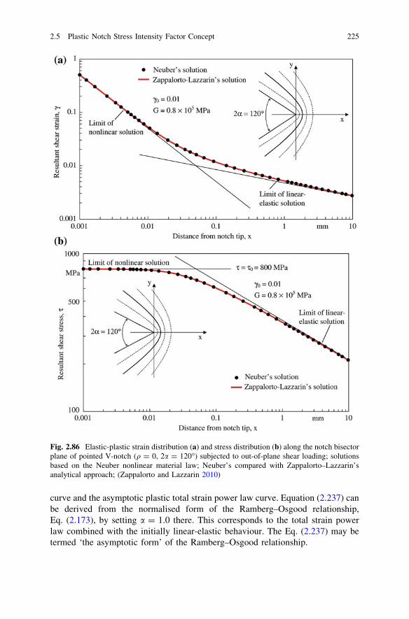
curve and the asymptotic plastic total strain power law curve. Equation (2.237) canbe derived from the normalised form of the Ramberg–Osgood relationship,Eq. (2.173), by setting a = 1.0 there. This corresponds to the total strain powerlaw combined with the initially linear-elastic behaviour. The Eq. (2.237) may betermed ‘the asymptotic form’ of the Ramberg–Osgood relationship.
Fig. 2.86 Elastic-plastic strain distribution (a) and stress distribution (b) along the notch bisectorplane of pointed V-notch (q = 0, 2a = 120�) subjected to out-of-plane shear loading; solutionsbased on the Neuber nonlinear material law; Neuber’s compared with Zappalorto–Lazzarin’sanalytical approach; (Zappalorto and Lazzarin 2010)
2.5 Plastic Notch Stress Intensity Factor Concept 225

A complete solution for V-notches with notch opening angle different from zeroby application of the above analytical tools is not possible, but the two limitconditions for s allow special solutions. The limit condition s!1 of purelyplastic behaviour at the notch tip results in the already derived Eqs. (2.235) and(2.236) with K3q = K3q,p. The limit condition s! 0 of linear-elastic behaviourresults in the Eqs. (2.232) and (2.233).
For the special case of a notch opening angle equal to zero corresponding topointed or blunt crack tips, a complete solution based on the asymptotic form ofthe Ramberg–Osgood relationship has been presented (Zappalorto and Lazzarin2010).
2.5.8 Plastic Zone Related to Elastic Higher Order Singularities
The higher order singularities at crack tips and V-notch tips are generally omittedin the linear-elastic analysis with the argument that the strain energy and thedisplacements in the near-tip region should remain bounded. But it has been shownthat the higher singular terms are significant in the elastic field outside the non-linear zone around the crack tip (Hui and Ruina 1995). Later on, it has been proventhat the higher order singular terms can be included in the elastic part of thecomplete elastic-plastic stress and strain field solutions for out-of-plane shearloading (Zappalorto and Lazzarin 2011(4)). The findings of the two authors justmentioned are summarised in the following.
At crack tips, higher order singularities of the order (1 - 2j)/2 with j = 2, 3, 4,5,… are found which are governed by the order 1 stress intensity factor KIII. TheNeuber material law, Eq. (2.287), is applied under small-scale yielding conditions.The higher order terms are found to be dependent, besides on KIII, on the substituteradius rp of the plastic zone around of the crack tip. The strains in the ligamentunder out-of-plane shear loading conditions read as follows, whereas the stressesresult from s = Gc:
c ¼ KIII
Gffiffiffiffiffiffiffiffi
2p xp 1þ rp
4xþ 1
32rp
x
2� 1
128rp
x
3� 5
2048rp
x
4þ. . .
� �
ð2:238Þ
rp ¼K2
III
2ps20
ð2:239Þ
For crack tips, now using the Ramberg–Osgood material law in the form ofEq. (2.237), Gc = s ? dsn with d ¼ s1�n
0 ¼ G=Hns , the following relationship is
derived, with the hardening exponent n = 4.0 as an example, once more in theligament under out-of-plane shear loading conditions:
226 2 Extended Stress Intensity Factor Concepts

s ¼ KIIIffiffiffiffiffiffiffiffi
2pxp 1þ 2p
3ffiffiffi
6p rp
x
�ffiffiffi
2p rp
x
3=2þ
ffiffiffi
2p
p2
9rp
x
2� 8
ffiffiffi
2p
p
3ffiffiffi
3p rp
x
5=2þ. . .
� �
ð2:240Þ
c ¼ 1Gðsþ ds4Þ ¼ 1
G1þ s
s0
� �3" #
s ðn ¼ 4Þ ð2:241Þ
The conclusion from Eqs. (2.238) and (2.240) is, that the intensities of thehigher order terms depend on the plastic zone radius rp, which is defined by thesubstitute yield limit s0 (not identical with the real yield limit sY).
The physical necessity of the higher order singular terms is proven on the basisof the strain energy density distribution. The asymptotic densities along the lig-ament in the elastic zone, We, and in the plastic zone, Wp, considering the Neubermaterial law are given by:
We ¼12
Gc2 ¼ K2III
4p G
1x
ð2:242Þ
Wp ¼ s0c ¼KIII
p G
1xðc� c0Þ ð2:243Þ
It is obvious from the above asymptotic behaviour, that the strain energydensity level in the plastic zone is four times greater than in the elastic zone with a
Fig. 2.87 Plastic (Wp) and elastic (We) strain energy density over distance x from the crack tip;substitute yield limit c0, c0 defines rp from linear-elastic analysis and xp from elastic-plasticanalysis (Zappalorto and Lazzarin 2011(4))
2.5 Plastic Notch Stress Intensity Factor Concept 227

smooth transition according to the complete solution, Fig. 2.87. The strain energydensity corresponding to the substitute yield limit c = c0 is given by:
W0 ¼ s0c0
ffiffiffi
2p� 1
ðc ¼ c0Þ ð2:244Þ
This strain energy density occurs on the ligament at the distance xp:
xp ¼ffiffiffi
2pþ ln 1þ
ffiffiffi
2p h i
rp ¼ 2:3 rp ð2:245Þ
For V-notch tips, similar relationships for the stress and strain field have beenderived by the same authors based on the Neuber material law under small-scaleyielding conditions. Here, it was found that the higher order terms are governed bythe first linear-elastic eigenvalues and not by higher order solutions. Once more,the higher order terms can be presented within a relationship governed by K3 anddependent on the radius rp of the substitute plastic zone around the V-notch tip.
The notch opening angle 2a = 135�, kð1Þ3 ¼ 0:8, is considered as an example.The strains in the bisector plane under out-of-plane shear loading conditions readas follows, whereas the stresses result from s = Gc:
c ¼ K3
Gffiffiffiffiffiffi
2pp
x1=51þ 1
3rp
x
2=5þ 1
8rp
x
4=5þ 5
54rp
x
6=5þ 41
2592rp
x
8=5þ. . .
� �
ð2:246Þ
rp ¼K3
s0
ffiffiffiffiffiffi
2pp
� �1=ð1�k3Þ¼ K3
s0
ffiffiffiffiffiffi
2pp
� �5
ð2:247Þ
The conclusion is that the higher order singular terms can fully be included inthe elastic part of the complete elastic-plastic stress and strain field solutions. Theintensity of these additional terms depends on the elastic stress intensity factor andthe substitute plastic zone radius rp.
2.5.9 Neuber Rule Including the Influence of the NotchOpening Angle
The reviewed analytical developments related to elastic-plastic fields at sharpnotches make it possible to include the influence of the notch opening angle in theNeuber rule where an unexpected effect in total is observed. Before presentingthese results in detail, the Neuber rule is explained in general. It refers to roundednotches with exclusion of pointed notches, in contrast to the NSIF approach, whichrefers to pointed notches with inclusion of rounded notches.
The elastic-plastic notch stresses and strains can be approximated by predom-inantly uniaxial models and correspondingly simple formulae. Widely used isNeuber’s ‘macrosupport formula’ besides an approximation by Glinka based on
228 2 Extended Stress Intensity Factor Concepts

the strain energy density. As soon as the yield limit is locally exceeded, the notchstresses rise underproportional and the notch strains overproportional. The relationbetween the elastic-plastic stress and strain concentration factors, Kr and Ke, on theone hand and the elastic stress concentration factor Kt on the other hand, is givenby Neuber for sharp and mild notches, respectively, by the following equations(Neuber 1961, 1968(1), 1961(2), 1985):
KrKe ¼ K2t ðKt � 1:0Þ ð2:248Þ
KrðKe � 1Þ ¼ KtðKt � 1Þ ð2:249Þ
These equations are expressed by the maximum notch stresses rk = rmax andmaximum notch strains ek = emax (in the elastic-plastic range) as well as by thenominal stresses rn and nominal strains en (in the elastic range) as follows:
rkek ¼ rnenK2t ¼
r2n
EK2
t ð2:250Þ
rkðek � enÞ ¼ rnenKtðKt � 1Þ ¼ r2n
EKtðKt � 1Þ ð2:251Þ
The content of Eqs. (2.248–2.251) is illustrated by Fig. 2.88, where the conditionof elastic nominal stresses and strains referring to the net cross-section is deleted infavour of possibly occurring elastic-plastic conditions. Conforming to Neuber’sanalysis, the maximum actual notch stresses and strains on the stress–strain curve ofthe material are determined starting from the maximum linear-elastic notch stressrkH = rmax,e (with appertaining maximum notch strain ekH) on the Hooke straightline curve. The connection between appertaining points on the two curves isestablished by hyperbola-like curve sections, which run flatter for sharp notches,
Fig. 2.88 Illustration of theanalysis of elastic-plasticnotch stresses and strains forsharp and mild notches;maximum notch stress rk,maximum notch strains ek,nominal stress rn, nominalstrain en, subscript H for‘Hooke’ (after Neuber 1961,1968(1), 1968(2), 1985)
2.5 Plastic Notch Stress Intensity Factor Concept 229

Eq. (2.250) and steeper for mild notches, Eq. (2.251). Thus, slightly higher notchroot stresses and strains are found with the former than with the latter equation.
The maximum linear-elastic notch stress rkH according to Hooke result fromthe Hooke nominal stress rnH (with appertaining nominal strain enH) by multi-plication with the elastic stress concentration factor Kt. The Hooke nominal stressis connected with the actual nominal stress rn (with appertaining nominal strain en)by the hyperbola-like curve sections mentioned above. They are slightly higherthan the actual nominal stress and differently high for the two curve sections. Thus,different values of rkH appear with the same value of Kt. The increase and thedifference in rkH disappear if the actual nominal stress rn remains linear-elastic.As can be seen from Fig. 2.88, too high notch stresses and notch strains aredetermined, if the original Neuber rule, Eq. (2.248), is applied to mild notches.
The Neuber rule was originally proposed based on general mathematical con-siderations on an appropriate ‘leading function’ (Neuber 1961). The Neuber for-mulae, Eqs. (2.248) and (2.250), were subsequently analytically derived forparabola-like notches subjected to out-of-plane shear loading with an arbitrarynonlinear material law (Neuber 1985, ibid. pp. 86–87). Actually, a parabolic notchwas the basis in combination with the Neuber material law in the unconventionalform Gc = s/(1 - s/s0). The law does not allow for hardening under large strains.The resulting formula was then rewritten in terms of tensile stresses and strainswith reference to the von Mises criterion.
As an alternative to the (original) Neuber rule, Glinka has proposed an approachbased on the strain energy density in order to determine the elastic-plastic stressesand strains (Glinka 1985). The assumption is introduced that the strain energydensity in the elastically supported plastic area at the notch tip (small-scaleyielding) remains equal to the value of the linear-elastic solution (equivalent strainenergy density concept). This assumption suggests itself for uniaxial and propor-tionally biaxial stress states, because the stresses and strains exceeding the yieldlimit deviate in opposite directions from the linear-elastic behaviour, whereas theprincipal directions of the stress and strain state remain unchanged. The Glinkaapproach offers a higher solution accuracy than the original Neuber formula. Thishas been proven on an experimental basis and was further substantiated by thefollowing comparison of the two approaches.
The comparison is based on the Ramberg–Osgood material law. It is simplified bythe assumption that the nominal stress remains in the linear-elastic range. The elasticstrain energy density rising with the squared product of nominal stress times stressconcentration factor is equated with the correspondingly rising elastic and plasticcomponents of the elastic-plastic strain energy density at the notch tip (Glinka 1985):
r2n
2EK2
t ¼r2
k
2Eþ rk
n0 þ 1rk
H
1=n0
ð2:252Þ
where 1/n0 is used instead on n as the hardening exponent (0 \ n0\ 1.0).The original Neuber equation in terms of the Ramberg–Osgood material law,
considered as a strain energy density equation, reads:
230 2 Extended Stress Intensity Factor Concepts

r2n
2EK2
t ¼rk
2rk
Eþ rk
H
1=n0� �
ð2:253Þ
The solutions according to Glinka (curve point G) and Neuber (curve point N)are contrasted in Fig. 2.89. The strain energy density Wn of the nominal stressappears as a hatched triangular area. The corresponding strain energy density Wk
of the maximum notch stress and strain is represented by the halftone area belowthe curve. The strain energy density according to the Neuber solution is charac-terised by the area below the straight line between the points 0 and N. The notchstrain according to Neuber is substantially larger than according to Glinka.Experimental data confirm Glinka’s result. Also, Neuber’s modified solution, Eq.(2.251), reduces the notch strain.
The plastic NSIF approach by Zappalorto and Lazzarin allows further com-parisons with the Neuber and Glinka results. The characteristic feature of thisapproach in respect of the Neuber rule is that the influence of the hardeningexponent n and of the notch opening angle 2a is explicitly taken into account.
A first relationship is gained from the elastic-plastic stress and strain fieldanalysis for parabolic notches (2a = 0) subjected to out-of-plane shear loading(Zappalorto and Lazzarin 2007). The material law consists of linear-elasticbehaviour up to the substitute yield limit s0 and power law behaviour in terms ofthe total strains above this limit. Continuing the exposition in Sect. 2.5.5, thefollowing equation for the elastic-plastic notch stresses and strains is derived:
smax; pcmax; p ¼ s0c02n
nþ 11
pqK3q; e
s0
� �2
¼ 2n
nþ 1ðsmax; eÞ2
Gð2:254Þ
By dividing both sides of the equation by sncn ¼ s2nG, one obtains the Neuber
rule in the following form:
KsKc ¼2n
nþ 1K2
t ð2:255Þ
Fig. 2.89 Illustration of theelastic-plastic notch stressand strain analytical solutionsby Glinka (point G) and byNeuber (point N); Glinka’ssolution on the basis of aconstant ratio of strain energydensities Wk und Wn; (Glinka1985)
2.5 Plastic Notch Stress Intensity Factor Concept 231

This relationship is different from Neuber’s original expression KsKc ¼ K2t by a
factor 1.0–2.0, identical only for the linear-elastic limit case (n = 1) and with thelargest deviation for the elastic perfectly-plastic material ðn!1Þ:
Based on the above analytical frame, an explicit formula for the maximumstress smax,p is derived:
smax; p ¼ s01
2pK3q; e
s0
� �22q
" #1=ðnþ1Þ
¼ ðs2max; es
n�10 Þ
1=ðnþ1Þ ð2:256Þ
Here, larger stresses and strains than with the original Neuber rule are found, incontrast to the tendency in Glinka’s experimental results, after conversion of thetensile stresses there to shear stresses here.
A second investigation is devoted exclusively to the Neuber rule, using theNeuber nonlinear material law (Zappalorto and Lazzarin 2009). Pointed androunded V-notches are considered, subjected to out-of-plane shear loading. The
basic plastic and elastic NSIF relationships are stated in Sect. 2.5.7: K3q,p, KðcÞ3q; p,
K3q,e, KðcÞ3q; e and also K3q,p = f (K3q,e) according to Eqs. (2.227–2.229).With the aim to check the Neuber rule, the following product is formulated:
K3q; pKðcÞ3q; p ¼ 2pc0s0bK3q; effiffiffiffiffiffi
2pp
s0
� �x1þ1
ð2:257Þ
b ¼ 21�x1ð1þ x1Þ; x1 ¼p
p� 2að2:258Þ
The plastic NSIFs in terms of the maximum stresses and strains read as follows:
K3q; p ¼ffiffiffiffiffiffi
2pp
smax; p; KðcÞ3q; p ¼ffiffiffiffiffiffi
2pp
cmax; pr0 ð2:259Þ
where r0 = q (q - 1)/q with (1 \ q \ 2) for hyperbolic notches and q = 2 forparabolic notches.
The elastic NSIF is given by the following expression (Zappalorto et al. 2008):
K3q; e ¼ffiffiffiffiffiffi
2pp
smax; er1�k30 ð2:260Þ
Equation (2.257) written in the maximum stresses and strains according to Eqs.(2.25) and (2.260) reads as follows:
smax; p cmax; p ¼ s0c0bsmax; e
s0
� �x1þ1
ð2:261Þ
where b and x1 are notch angle dependent parameters. Thus, the product of thestress and strain concentrations depends on the notch opening angle, contrary tothe original Neuber rule.
In the special case of the parabolic notch (2a = 0, x1 = 1, b = 2), Eq. (2.261)results in:
232 2 Extended Stress Intensity Factor Concepts

smax; p cmax; p ¼2s2
max; e
Gð2:262Þ
Ks Kc ¼ 2K2t ð2:263Þ
This result confirms Eq. (2.255) for n!1, the condition, which brings the twodifferent material laws more or less in correspondence (elastic perfectly-plasticbehaviour).
The difference between Neuber’s and Zappalorto–Lazzarin’s final formulae,both derived for the same nonlinear material law, is discussed in detail by thesecond-mentioned authors. They uncover an inconsistency in Neuber’s derivation,which expresses itself in the factor 1 instead of 2 on the nonlinear strains. But theremoval of this deficiency does not solve the problem. Obviously, Neuber’s ori-ginal formula is applicable when approaching the limit case of purely elasticmaterial behaviour. This is an indication that Neuber’s original formula isappropriate in the range of small-scale yielding. Experimental and numerical (FEanalysis) investigations have repeatedly demonstrated the applicability of theoriginal formula with the reservation of a modification for mild notches. Themodification has the effect that the resulting notch strains are slightly reduced. Onthe other hand, Zappalorto and Lazzarin’s relationships, Eqs. (2.255) and (2.263),are appropriate for the extremely large plastic strains which occur close to pointednotch tips.
2.5.10 Analytical Description of Elastic-Plastic MaterialBehaviour
The analytical HRR and Neuber solutions for the stress and strain field at sharpnotches under the condition of elastic-plastic material behaviour are actuallynonlinear-elastic solutions. The solutions are bound to the condition of monotonicloading in every point of the field. Any unloading, globally or locally, is notallowed. The plastic strains are simply the nonlinear strain components, total strainminus linear-elastic strain. This condition applies to the analytical solutions andmust be ascertained in comparative models using the FE method. The demandingmathematical formulations are easier to understand, if one considers them asreferring to nonlinear-elastic material behaviour. Different types and variants ofnonlinear material laws are in use.
Uniaxial Ramberg–Osgood Material Law
The relationship between stresses and strains in uniaxial monotonic loading, whichis widely used by engineers, is the Ramberg–Osgood material law describing asingle smooth curve without a distinct yield limit, Fig. 2.90:
2.5 Plastic Notch Stress Intensity Factor Concept 233

e ¼ ee þ ep ¼rEþ r
H
nð2:264Þ
with the elastic strain ee, the plastic strain ep, the modulus of elasticity E, thehardening (or strength) coefficient H and the hardening exponent n. The exponentn is determined from log r over log e plots. For the metallic engineering materials,n = 2.5–20.0 is found. In low-cycle fatigue assessments, a corresponding cyclicRamberg–Osgood relationship is used. The cyclic material parameters may deviatesubstantially from the monotonic ones.
In engineering science, the offset yield limit rY0.2 is introduced, which denotesthe stress where a plastic strain eY0.2 = 0.2 % occurs. Therefore, the followingformula applies:
ep
eY0:2¼ r
rY0:2
� �n
ðeY0:2 ¼ 0:002Þ ð2:265Þ
Equating ep from Eq. (2.264) and (2.265) gives:
rY0:2 ¼ e1=nY0:2H ð2:266Þ
which means that rY0.2 depends on n and H for a defined eY0.2 and is not a thirdindependent material parameter.
Multiaxial Ramberg–Osgood Material Law
The Ramberg–Osgood material law, generalised for multiaxial stress conditions, isusually presented in tensor form related to the stress and strain components,Eq. (2.183). Rather lengthy expressions for stresses, strains and strain energiesresult from it. A simplified procedure, preferred by engineers, is possible. Thenecessary conditions are monotonic loading, constant ratios of the stress
Fig. 2.90 Ramberg–Osgood material law: stress–strain curves drawn in linear (a) and logarith-mic (b) coordinates; (Dowling 1993)
234 2 Extended Stress Intensity Factor Concepts

components and validity of the octahedral shear stress criterion (corresponding tothe von Mises criterion). Then, according to Hencky’s approach (Hencky 1924;Chakrabarty 2006), the components of the plastic strain tensor are set proportionalto the components of the coaxial deviatoric stress tensor:
eij; p ¼ ksij ð2:267Þ
For work-hardening materials, the coefficient k depends on the von Misesequivalent stress req, which is considered to be a function of the equivalent plasticstrain ep,eq:
req ¼ffiffiffiffiffiffiffiffiffiffiffiffi
32
sijsij
r
ð2:268Þ
eeq; p ¼ffiffiffiffiffiffiffiffiffiffiffiffiffiffiffiffiffiffi
23eij; peij; p
r
ð2:269Þ
The relationship between req and eeq,p is given by the uniaxial stress versusplastic strain curve. The coefficient k can be expressed by req and eeq,p or by thesecant modulus Ep according to Eq. (2.270):
k ¼ 3eeq; p
2req
¼ 32Ep
ð2:270Þ
It is a peculiarity of Hencky’s approach that the coefficient k is related to thestress–strain curve. In its original, more general definition, it is a constant factorwhich denotes the occurrence of plastic strain rates or strain increments as cor-related with the deviatoric stress state.
The von Mises equivalent stress req expressed by the principal stresses r1, r2,r3 is related to the octahedral shear stress so:
req ¼12
ffiffiffiffiffiffiffiffiffiffiffiffiffiffiffiffiffiffiffiffiffiffiffiffiffiffiffiffiffiffiffiffiffiffiffiffiffiffiffiffiffiffiffiffiffiffiffiffiffiffiffiffiffiffiffiffiffiffiffiffiffiffiffiffiffiffiffiffiffiffiffiffiffiffi
ðr1 � r2Þ2 þ ðr2 � r3Þ2 þ ðr3 � r1Þ2q
¼ 3ffiffiffi
2p so ð2:271Þ
The corresponding equivalent plastic strain eeq,p expressed by the principalplastic strains e1,p, e2,p, e3,p is related to the octahedral plastic shear strain co,p:
eeq; p ¼ffiffiffi
2p
3
ffiffiffiffiffiffiffiffiffiffiffiffiffiffiffiffiffiffiffiffiffiffiffiffiffiffiffiffiffiffiffiffiffiffiffiffiffiffiffiffiffiffiffiffiffiffiffiffiffiffiffiffiffiffiffiffiffiffiffiffiffiffiffiffiffiffiffiffiffiffiffiffiffiffiffiffiffiffiffiffiffiffiffiffiffiffiffiffi
ðe1; p � e2; pÞ2 þ ðe2; p � e3; pÞ2 þ ðe3; p � e1; pÞ2q
¼ 1ffiffiffi
2p co; p ð2:272Þ
The equivalent total strain eeq is the sum of its elastic and plastic components:
eeq ¼req
Eþ eeq; p ð2:273Þ
The equivalent stress and strain, req and eeq,p or eeq, is identical with the stressand strain, r1 and e1,p or e1, in the uniaxial tensile test case (req = r1,r2 = r3 = 0, eeq,p = e1,p, e2,p = e3,p = -0.5e1,p) so that any monotonic stress–strain curve is a sufficient basis for describing arbitrary stress and strain states. The
2.5 Plastic Notch Stress Intensity Factor Concept 235
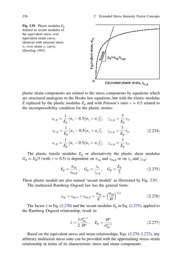
plastic strain components are related to the stress components by equations whichare structured analogous to the Hooke law equations, but with the elastic modulusE replaced by the plastic modulus Ep and with Poisson’s ratio m = 0.5 related tothe incompressibility condition for the plastic strains:
ex; p ¼1
Ep
rx � 0:5 ry þ rz
�� �
; cxy; p ¼3
Ep
sxy
ey; p ¼1
Ep
ry � 0:5 rx þ rzð Þ� �
; cyz; p ¼3
Ep
syz
ez; p ¼1
Ep
rz � 0:5 rx þ ry
�� �
; czx; p ¼3
Ep
szx
ð2:274Þ
The plastic tensile modulus Ep or alternatively the plastic shear modulusGp = Ep/3 (with m = 0.5) is dependent on req and eeq,p or on so and co,p:
Ep ¼req
eeq; p; Gp ¼
so
co; p
; Gp ¼Ep
3ð2:275Þ
These plastic moduli are also named ‘secant moduli’ as illustrated by Fig. 2.91.The multiaxial Ramberg–Osgood law has the general form:
eeq ¼ eeq; e þ eeq; p ¼req
Eþ req
H
1=nð2:276Þ
The factor k in Eq. (2.270) and the secant modulus Ep in Eq. (2.275), applied tothe Ramberg–Osgood relationship, result in:
k ¼ 32
rn�1eq
Hn; Ep ¼
Hn
rn�1eq
ð2:277Þ
Based on the equivalent stress and strain relationships, Eqs. (2.270–2.272), anyarbitrary multiaxial stress state can be provided with the appertaining stress–strainrelationship in terms of its characteristic stress and strain components.
Fig. 2.91 Plastic modulus Ep
defined as secant modulus ofthe equivalent stress overequivalent strain curve,identical with uniaxial stressr1 over strain e1 curve;(Dowling 1993)
236 2 Extended Stress Intensity Factor Concepts
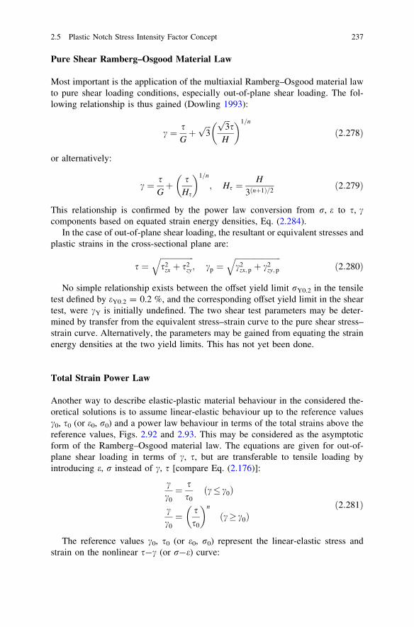
Pure Shear Ramberg–Osgood Material Law
Most important is the application of the multiaxial Ramberg–Osgood material lawto pure shear loading conditions, especially out-of-plane shear loading. The fol-lowing relationship is thus gained (Dowling 1993):
c ¼ sGþ
ffiffiffi
3p ffiffiffi
3p
sH
� �1=n
ð2:278Þ
or alternatively:
c ¼ sGþ s
Hs
� �1=n
; Hs ¼H
3ðnþ1Þ=2ð2:279Þ
This relationship is confirmed by the power law conversion from r, e to s, ccomponents based on equated strain energy densities, Eq. (2.284).
In the case of out-of-plane shear loading, the resultant or equivalent stresses andplastic strains in the cross-sectional plane are:
s ¼ffiffiffiffiffiffiffiffiffiffiffiffiffiffiffiffiffi
s2zx þ s2
zy
q
; cp ¼ffiffiffiffiffiffiffiffiffiffiffiffiffiffiffiffiffiffiffiffiffiffiffi
c2zx; p þ c2
zy; p
q
ð2:280Þ
No simple relationship exists between the offset yield limit rY0.2 in the tensiletest defined by eY0.2 = 0.2 %, and the corresponding offset yield limit in the sheartest, were cY is initially undefined. The two shear test parameters may be deter-mined by transfer from the equivalent stress–strain curve to the pure shear stress–strain curve. Alternatively, the parameters may be gained from equating the strainenergy densities at the two yield limits. This has not yet been done.
Total Strain Power Law
Another way to describe elastic-plastic material behaviour in the considered the-oretical solutions is to assume linear-elastic behaviour up to the reference valuesc0, s0 (or e0, r0) and a power law behaviour in terms of the total strains above thereference values, Figs. 2.92 and 2.93. This may be considered as the asymptoticform of the Ramberg–Osgood material law. The equations are given for out-of-plane shear loading in terms of c, s, but are transferable to tensile loading byintroducing e, r instead of c, s [compare Eq. (2.176)]:
cc0¼ s
s0ðc c0Þ
cc0¼ s
s0
� �n
ðc c0Þð2:281Þ
The reference values c0, s0 (or e0, r0) represent the linear-elastic stress andstrain on the nonlinear s-c (or r-e) curve:
2.5 Plastic Notch Stress Intensity Factor Concept 237

c0 ¼s0
G¼ s0
Hs
� �n
; s0 ¼Hn
s
G
� �1=ðn�1Þð2:282Þ
e0 ¼r0
E¼ r0
H
n; r0 ¼
Hn
E
� �1=ðn�1Þð2:283Þ
There is no difference between the total strain power law and the Ramberg–Osgoodrelationship for very large strains, as they occur in the close vicinity of the notch tip, sothat n and Hs or H can be set equal, but there are major differences in the values of c0,s0 (or e0, r0) compared with those of cY, sY (or eY, rY), Fig. 2.94. The mentioneddifferences are relevant when considering the plastic zone size. One has to differen-tiate between the real size defined by eY, rY and the substitute size given by e0, r0.
In order to avoid confusion when comparing NSIF values from analyticalexpressions based on the total strain power law with those from FE analysis based
Fig. 2.93 Linear-elastic followed by total strain power law material behaviour: normalisedstress–strain curves drawn in linear coordinates; (Lazzarin and Zappalorto 2008)
Fig. 2.92 Linear–elastic followed by total strain power law material behaviour: stress–straincurves drawn in linear (a) and logarithmic (b) coordinates; (Dowling 1993)
238 2 Extended Stress Intensity Factor Concepts
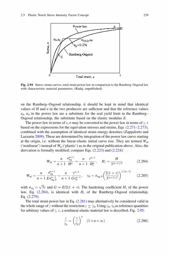
on the Ramberg–Osgood relationship, it should be kept in mind that identicalvalues of H and n in the two producers are sufficient and that the reference valuese0, r0 in the power law are a substitute for the real yield limit in the Ramberg–Osgood relationship, the substitute based on the elastic modulus E.
The power law in terms of e, r may be converted to the power law in terms of c, sbased on the expressions for the equivalent stresses and strains, Eqs. (2.271–2.273),combined with the assumption of identical strain energy densities (Zappalorto andLazzarin 2009). These are determined by integration of the power law curve startingat the origin, i.e. without the linear-elastic initial curve rise. They are termed Wnl
(‘nonlinear’) instead of Wp (‘plastic’) as in the original publication above. Also, thederivation is formally modified; compare Eqs. (2.223) and (2.224):
Wnl ¼n
nþ 1
rnþ1eq
Hn¼ n
nþ 1snþ1
Hns; Hs ¼
H
3ðnþ1Þ=2ð2:284Þ
Wnl ¼n
nþ 1
rnþ1eq
Ern�1eq; 0
¼ n
nþ 1snþ1
Gsn�10
; s0 ¼ req; 02ð1þ mÞ3ðnþ1Þ=2
� �1=ðn�1Þð2:285Þ
with req ¼ffiffiffi
3p
s and G = E/2(1 ? m). The hardening coefficient Hs of the powerlaw, Eq. (2.284), is identical with Hs of the Ramberg–Osgood relationship,Eq. (2.279).
The total strain power law in Eq. (2.281) may alternatively be considered valid inthe whole range of c without the restriction c C c0. Using c0, s0 as reference quantitiesfor arbitrary values of c, s, a nonlinear-elastic material law is described, Fig. 2.95:
cc0¼ s
s0
� �n
ð1\n\1Þ ð2:286Þ
Fig. 2.94 Stress–strain curves, total strain power law in comparison to the Ramberg–Osgood lawwith characteristic material parameters; (Radaj, unpublished)
2.5 Plastic Notch Stress Intensity Factor Concept 239
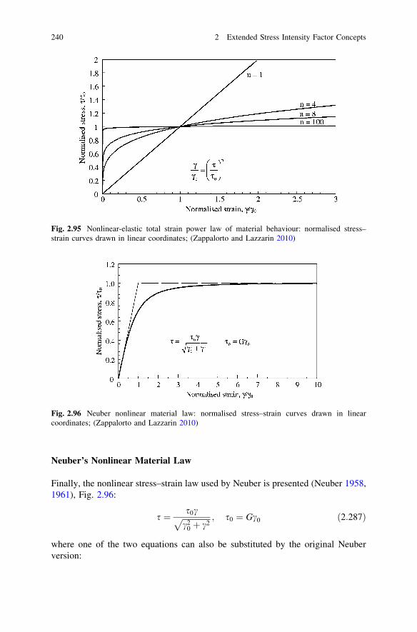
Neuber’s Nonlinear Material Law
Finally, the nonlinear stress–strain law used by Neuber is presented (Neuber 1958,1961), Fig. 2.96:
s ¼ s0cffiffiffiffiffiffiffiffiffiffiffiffiffiffi
c20 þ c2
p ; s0 ¼ Gc0 ð2:287Þ
where one of the two equations can also be substituted by the original Neuberversion:
Fig. 2.96 Neuber nonlinear material law: normalised stress–strain curves drawn in linearcoordinates; (Zappalorto and Lazzarin 2010)
Fig. 2.95 Nonlinear-elastic total strain power law of material behaviour: normalised stress–strain curves drawn in linear coordinates; (Zappalorto and Lazzarin 2010)
240 2 Extended Stress Intensity Factor Concepts
Gc ¼ sffiffiffiffiffiffiffiffiffiffiffiffiffiffiffiffiffiffiffiffiffiffiffi
1� ðs=s0Þ2q ð2:288Þ
This material law has the following properties: s! s0 for c!1; s! Gc forc! 0 and a continuous strain hardening behaviour in the c range between.Virtually no hardening occurs for values c/c0 C 5.0. A stress singularity at pointednotches cannot be formed under these conditions, but a strain singularity very well.
The different material laws reviewed above will have an influence on the stressand strain fields at pointed or rounded notches. This influence manifests itself indifferent plastic NSIFs. Therefore, the plastic NSIFs depend on the material law.An exception is non-hardening material behaviour, where the plastic NSIFs areidentical.
2.5.11 Conclusions
The elastic-plastic stress and strain fields at pointed or rounded notch tips can beuniformly described by plastic NSIFs as governing parameters. The plastic NSIFsare combined for that purpose with definite ‘universal functions’. Both the stressand strain fields are handled within this analytical frame, differentiating betweenstress intensity factors and strain intensity factors. Definite relationships existbetween elastic and plastic NSIFs, or, following the loading curve, between initiallinear and final nonlinear NSIFs.
The available analytical solutions are derived for nonlinear-elastic materiallaws which may be interpreted as elastic-plastic behaviour under conditions ofmonotonic loading. Two different material laws are the basis of the analyticaltheory: the Ramberg–Osgood relationship asymptotically approximated by thetotal strain power law for strain-hardening materials (the HRR solutions) andNeuber’s material law without hardening at large strains. These material lawsallow closed form solutions for the antiplane fields and approximate solutions forthe in-plane fields.
There remains the problem, how to interpret the derived analytical solutions interms of the Ramberg–Osgood material law which is preferred by engineers andactually fits the real-world material behaviour better than the power material lawor the Neuber material law does. There is no problem with the limit states of smallelastic strains and large plastic strains at the notch tip, but there is a problem in theintermediate range, where the elastic-plastic boundary is established.
Valuable basic insights have been gained in respect of the following engi-neering issues, mainly under small-scale yielding conditions: plastic NSIFs forV-notches and parabolic notches, the size effect for V-notched specimens,expressions for the strain energy density and the J-integral, elastic-plastic stressand strain distributions in the bisector plane for various notch opening angles. Thesolutions for configurations with finite geometries are scaled by FE-analysis
2.5 Plastic Notch Stress Intensity Factor Concept 241

results. The Neuber rule for extremely large strains is specified in terms ofhardening exponent and notch opening angle for the extremely large strains atpointed notch tips.
2.6 Stress Intensity Factor Concept for Rigid Inclusions
2.6.1 Survey of Section Contents
Any geometrical or material discontinuity in an, apart from this, homogeneouselastic continuum produces local stress concentrations when the continuum or thediscontinuity is subjected to any loadings. At the pointed edges of such discon-tinuities stress singularities occur. The stress singularities at crack tips, a geo-metrical discontinuity, are well known. When the crack is substituted by a rigidthin inclusion (also termed ‘layer’, ‘lamella’ or simply ‘line’), the stresses at thepointed tip of the inclusion remain singular.
This is also the case if the thin inclusion is not rigid, but only stiffer or less stiffthan the surrounding material. The thin inclusion can have membrane stiffness,bending stiffness or both. Rigid or elastic thin inclusions are of some applicationrelevance in respect of coated or bonded members, lamella-reinforced compositesand materials containing flat inclusions.
Despite a limited practical applicability of the thin inclusion models comparedwith crack models, a remarkable number of analytical solutions has been published(e.g. Sih 1965; Brussat and Westermann 1975; Wang et al. 1985, 1986; Chen 1986,1991, 1992; Chen and Cheung 1987; Cheung and Chen 1989). Evaluation of thesecontributions shows that a sufficiently complete systematics of the basic loadingmodes (singular and non-singular) is not available, that the stress intensity factorsare differently defined, and that the relevant limit value formulae are only partiallygiven. The exposition below is based on a uniform redefinition of the basic modelsand their analytical treatment by the Kolosov–Muskhelishvili complex stressfunction theory (Radaj and Zhang 1993(2)).
The basic loading modes at rigid thin inclusion tips are defined in analogy to thebasic loading modes at crack tips. The stresses and displacements in the closevicinity of these tips are described in a uniform format by stress intensity factors,angular functions and non-singular terms. The limit value formulae for the stressintensity factors are given. The flat and curved rigid thin inclusion is considered asan example of practical application.
The concept is open for extensions to wedge-shaped rigid inclusions withoutand with wedge tip rounding (Hasebe et al. 1990).
242 2 Extended Stress Intensity Factor Concepts

2.6.2 Basic Loading Modes at Rigid Thin Inclusion Tips
The basic loading modes at the tips of a rigid thin inclusion are defined inanalogy to the basic loading modes at crack tips. The basic singular loadingmodes I*, II* and III* are shown in Fig. 2.97. A rigid thin inclusion strip per-meates an infinite elastic body (or continuum). This configuration is substitutedby a plate of finite thickness containing the inclusion. The multiaxiality conditionwith mode I* and mode II* loading is plane strain. Otherwise, out-of-planesingular effects will occur where the inclusion front line butts on the platesurface. The solutions below are also given for plane stress conditions, but this isonly of academic interest. In mode III* loading, the out-of-plane deflections ofthe plate surfaces correspond to the condition in the out-of-plane shear loadedinfinite body. Mode I* loading is characterised by longitudinal in-plane tensile(or compressive) basic stresses, mode II* loading by transverse in-plane basicshear stresses and mode III* loading by out-of-plane basic shear stresses. Thebasic stress state may be produced by a resultant force or moment (Fx, Fy, Fz,M), or by remote boundary stresses (r, s*).
The basic non-singular loading modes 0I*, 0II* and 0III* are shown in Fig. 2.98.Mode 0I* loading is defined by triaxial tensile (or compressive) basic stresses (r0x,r0y, r0z) which suppress any displacement in the plane of the inclusion,e0x = e0z = 0, resulting in r0x = r0z = r0ym/(1 - m). Mode 0II* loading is definedby in-plane basic shear stresses s0, which have no stress raising effect at the
Fig. 2.97 Basic singular loading modes I*(a), II*(b) and III*(c) of rigid thin inclusion in infiniteplate; plane and antiplane strain fields; arrows designate remote boundary stresses or resultantforces acting on the inclusion; (Radaj and Zhang 1993(2))
2.6 Stress Intensity Factor Concept for Rigid Inclusions 243

inclusion. The same applies to mode 0III* loading by out-of-plane basic shearstresses s�0:
The analogy with the relevant crack models is obvious in respect of theirnumber (three singular and three non-singular loading modes) and in respect ofsome basic characteristics, but the external or internal loading conditions are notthe same.
2.6.3 Asymptotic Stress Field Close to Rigid Thin Inclusion Tips
The three basic loading modes with singular stresses at the rigid thin inclusion tipproduce the following asymptotic stress distribution close to these tips. Actually, acrack with the flank sides rigidly supported is considered, Fig. 2.99:
rij ¼1ffiffiffiffiffiffiffiffi
2prp K�I f �I;ijðhÞ þ K�IIf
�II; ijðhÞ þ K�IIIf
�III; kzðhÞ
h i
ði, j ¼ x; y and k ¼ x; y or i, j ¼ r; h and k ¼ r; hÞð2:289Þ
The mode-related stress intensity factors K�I ; K�II and K�III depend on the mag-nitude of the load, the length of the rigid thin inclusion and further geometricalparameters of the considered configuration. The mode-related functionsf �I; ijðhÞ; f �II; ijðhÞ and f �I; ijðhÞ, describe the angular distribution of the stresses at theinclusion tip. The relationship above is strictly valid for r ! 0 and approximatelyvalid for values of r which are small in relation to the inclusion length and othergeometrical parameters of the configuration.
The three basic loading modes with non-singular stresses at the rigid thininclusion tip are simply identical with the basic tensile and shear stresses inCartesian format shown in Fig. 2.98. Their conversion into the polar coordinatesystem is elementary.
Fig. 2.98 Basic non-singular loading modes 0I*(a), 0II*(b) and 0III*(c) of rigid thin inclusion ininfinite plate; plane and antiplane strain fields; arrows designate remote boundary stresses; (Radajand Zhang 1993(2))
244 2 Extended Stress Intensity Factor Concepts
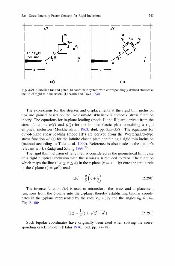
The expressions for the stresses and displacements at the rigid thin inclusiontips are gained based on the Kolosov–Muskhelishvili complex stress functiontheory. The equations for in-plane loading (mode I* and II*) are derived from thestress functions u(f) and w(f) for the infinite elastic plate containing a rigidelliptical inclusion (Muskhelishvili 1963, ibid. pp. 355–358). The equations forout-of-plane shear loading (mode III*) are derived from the Westergaard–typestress function u* (z) for the infinite elastic plate containing a rigid thin inclusion(method according to Tada et al. 1999). Reference is also made to the author’srelevant work (Radaj and Zhang 1993(2)).
The rigid thin inclusion of length 2a is considered as the geometrical limit caseof a rigid elliptical inclusion with the semiaxis b reduced to zero. The functionwhich maps the line (-a B x B a) in the z-plane (z = x ? iy) onto the unit circlein the f-plane (f = qeih) reads:
zðfÞ ¼ a
2fþ 1
f
� �
ð2:290Þ
The inverse function f(z) is used to retransform the stress and displacementfunctions from the f-plane into the z-plane, thereby establishing bipolar coordi-nates in the z-plane represented by the radii r0, r1, r2 and the angles h0, h1, h2,Fig. 2.100:
fðzÞ ¼ 1aðz�
ffiffiffiffiffiffiffiffiffiffiffiffiffiffi
z2 � a2p
Þ ð2:291Þ
Such bipolar coordinates have originally been used when solving the corre-sponding crack problem (Hahn 1976, ibid. pp. 77–78).
Fig. 2.99 Cartesian (a) and polar (b) coordinate system with correspondingly defined stresses atthe tip of rigid thin inclusion; (Lazzarin and Tovo 1998)
2.6 Stress Intensity Factor Concept for Rigid Inclusions 245

The stress and displacement equations for in-plane loading conditions (mode I*
and II*) are valid both for plane strain (ez = 0) and plane stress (rz = 0) condi-tions, using different expressions for the parameter j:
j ¼ 3� 4m ez ¼ 0ð Þ ð2:292Þ
j ¼ 3� m1þ m
rz ¼ 0ð Þ ð2:293Þ
where 0 B m B 0.5 is the Poisson’s ratio, resulting in 1 B j B 3 for plane strain or5/3 B j B 3 for plane stress. For structural steels with m = 0.28–0.30, the planestrain condition results in j = 1.8–1.9.
The mode I* loading condition (longitudinal tension or compression) at therigid thin inclusion is considered by the examples of remote longitudinal tension rand of a longitudinal force Fx applied to the inclusion, Fig. 2.97a. The completeequations of the stress functions, the stresses (rx, ry, sxy) and the displacements (u,v) are reduced to the following relationships in the close vicinity of the inclusiontip (r = r1, h = h1, r � a), neglecting terms which are small of higher order(Radaj and Zhang 1993(2)):
rx
ry
sxy
8
<
:
9
=
;
¼ K�Iffiffiffiffiffiffiffiffi
2prp
cos h=2 ð3þ j� 2 sin h=2 sin 3h=2Þcos h=2 ð1� jþ 2 sin h=2 sin 3h=2Þsin h=2 ð1þ jþ 2 cos h=2 cos 3h=2Þ
8
<
:
9
=
;
ð2:294Þ
uv
� �
¼ K�Ip G
ffiffiffiffiffiffiffiffi
2prp cos h=2 ðjþ sin2 h=2Þ
� sin h=2 cos2 h=2
� �
ð2:295Þ
where G is the shear modulus which may be expressed in terms of the elasticmodulus E by G = E/2(1 ? m).
The stress intensity factors in the two considered loading cases are:
K�I ¼1þ j
8jrffiffiffiffiffiffi
p ap
ð2:296Þ
Fig. 2.100 Bipolarcoordinates at rigid thininclusion of length 2a ininfinite plate (Radaj andZhang 1993(2))
246 2 Extended Stress Intensity Factor Concepts

K�I ¼1
2ð1þ jÞFxffiffiffiffiffiffi
p ap ð2:297Þ
These SIFs at the inclusion tip are smaller than the SIFs in the comparable crackloading cases (KI = r(pa)1/2, KI = Fx/(pa)1/2). Similar definitions of the SIFs arefound in the literature (Sih 1965; Wang et al. 1985).
Some further phenomena are worth to be mentioned. In the loading case oflongitudinal tension r, a constant transverse tensile stress ry = r(j - 1/j)/8 isacting on both sides of the rigid inclusion (non-reduced equations, -a B x B a),equilibrated by transverse compressive stress singularities ahead of the inclusiontips. The tensile force Tx in the rigid inclusion (per unit of plate thickness) isdetermined from sxy at h = p and h = -p, adding up the two values and inte-grating them starting at the inclusion tip (r = 0):
Tx ¼ 4ð1þ jÞK�Iffiffiffiffiffiffi
r
2p
r
ðr � aÞ ð2:298Þ
The mode II* loading condition (transverse shear loading) at the rigid thininclusion is considered by the examples of a turning moment M and of a transverseforce Fy applied to the inclusion, Fig. 2.97b. The complete equations of the stressfunctions, the stresses (rx, ry, sxy) and the displacements (u, v) are reduced to thefollowing relationships in the close vicinity of the inclusion tip (r = r1, h = h1,r � a), neglecting terms which are small of higher order (Radaj and Zhang1993(2)):
rx
ry
sxy
8
<
:
9
=
;
¼ K�IIffiffiffiffiffiffiffiffi
2prp
sin h=2 ð�3þ j� 2 cos h=2 cos 3h=2Þsin h=2 ð�1� jþ 2 cos h=2 cos 3h=2Þcos h=2 ð1� j� 2 sin h=2 sin 3h=2Þ
8
<
:
9
=
;
ð2:299Þ
uv
� �
¼ K�IIp G
ffiffiffiffiffiffiffiffi
2prp sin h=2 cos2 h=2Þ
� cos h=2 ðj� sin2 h=2
� �
ð2:300Þ
The stress intensity factors in the two considered loading cases are:
K�II ¼1
ð1þ jÞM
affiffiffiffiffiffi
p ap ð2:301Þ
K�II ¼1
2ð1þ jÞFyffiffiffiffiffiffi
pap ð2:302Þ
The transverse force Ty in the rigid inclusion (per unit of plate thickness) isdetermined from ry at h = p and h = -p, adding up the two values and inte-grating them proceeding from the inclusion tip (r = 0):
2.6 Stress Intensity Factor Concept for Rigid Inclusions 247

Ty ¼ �4ð1þ jÞK�IIffiffiffiffiffiffi
r
2p
r
ðr � aÞ ð2:303Þ
The mode III* loading condition (out-of-plane shear loading) at the rigid thininclusion is considered by the examples of remote out-of-plane shear stress s�andof an out-of-plane force Fz applied to the inclusion, Fig. 2.97c. The Westergaard-type stress function u�(z) for the two loading cases has been defined based on moregeneral equations (Tada et al. 1973, p. 1.23). The stresses (sxz, syz) and dis-placements w are derived therefrom in bipolar coordinates. The reduction to thestresses and displacements in the close vicinity of the inclusion tip is then per-formed (Radaj and Zhang 1993(2)). A solution available from the literature is basedon Poisson’s potential equation for the displacement function (Wang et al. 1986).The reduced equations for r � a read:
sxz
syz
� �
¼ K�IIIffiffiffiffiffiffiffiffi
2prp cos h=2
sin h=2
� �
ð2:304Þ
w ¼ K�IIIpG
ffiffiffiffiffiffiffiffi
2prp
cos h=2 ð2:305Þ
The stress intensity factors in the two considered loading cases are:
K�III ¼ s�ffiffiffiffiffiffi
pap
ð2:306Þ
K�III ¼Fz
2ffiffiffiffiffiffi
pap ð2:307Þ
The out-of-plane shear force Tz in the rigid inclusion (per unit of plate thick-ness) is determined from syz at h = p and h = -p, adding up the two values andintegrating them proceeding from the inclusion tip (r = 0):
Tz ¼ 4K�III
ffiffiffiffiffiffi
r
2p
r
ðr � aÞ ð2:308Þ
2.6.4 Limit Value Formulae for Stress Intensity Factors at RigidThin Inclusion Tips
The stress intensity factors K�I ; K�II; K�III at rigid thin inclusion tips can be deter-mined from any of the stress and displacement equations for mode I*, II*, III*
loading in any polar plane, but the ligament plane (h = 0) is best suited for thatpurpose because of the characteristic stresses in that plane and because the stressesfrom different modes acting simultaneously can be separated here. The followinglimit value formulae are applicable evaluating the stresses in the ligament plane(h = 0), Eqs. (2.294), (2.299) and (2.304):
248 2 Extended Stress Intensity Factor Concepts

K�I ¼ limr!0
rx
ffiffiffiffiffiffiffiffi
2prp
3þ jð2:309Þ
K�II ¼ limr!0
sxy
ffiffiffiffiffiffiffiffi
2prp
1� jð2:310Þ
K�III ¼ limr!0
sxz
ffiffiffiffiffiffiffiffi
2prp
ð2:311Þ
Evaluation of the displacements in the ligament plane, Eqs. (2.295), (2.300) and(2.305) gives:
K�I ¼ limr!0
p G
juffiffiffiffiffiffiffiffi
2prp ð2:312Þ
K�II ¼ limr!0
�p G
jvffiffiffiffiffiffiffiffi
2prp ð2:313Þ
K�III ¼ limr!0
p Gwffiffiffiffiffiffiffiffi
2prp ð2:314Þ
Evaluation of the forces in the inclusion Eqs. (2.298), (2.303) and (2.308),results in:
K�I ¼ limr!0
p2ð1þ jÞ
Txffiffiffiffiffiffiffiffi
2prp ð2:315Þ
K�II ¼ limr!0
�p2ð1þ jÞ
Tyffiffiffiffiffiffiffiffi
2prp ð2:316Þ
K�III ¼ limr!0
p2
Tzffiffiffiffiffiffiffiffi
2prp ð2:317Þ
Another limit value procedure for determining the stress intensity factor at therigid inclusion tip is based on the notch stress concentration in the principal plane(h = 0) of the comparable rigid elliptical inclusion. Evaluating formulae for theloading cases of remote tension loading (mode I*), transverse shear loading (modeII*) and out-of-plane shear loading (mode III*), the following limit values for thenotch radius q! 0 are found (Radaj 1971; Radaj and Schilberth 1977; Mura1987; Radaj and Zhang 1993(2)):
K�I ¼ limq!0
11þ j
rx max
ffiffiffiffiffiffi
pqp ð2:318Þ
K�II ¼ limq!0
�11þ j
sxy max
ffiffiffiffiffiffi
pqp ð2:319Þ
K�III ¼ limq!0
sxz max
ffiffiffiffiffiffi
pqp ð2:320Þ
2.6 Stress Intensity Factor Concept for Rigid Inclusions 249

2.6.5 Example of Stress Intensity Factor Evaluation
The limit value formulae, Eqs. (2.309–2.317) allow to determine unknown stressintensity factors at rigid thin inclusion tips based on a FE or boundary elementanalysis of the stresses and displacements in the ligament plane (h = 0). As anexample of application, a boundary element analysis has been performed for a flatand a curved (quarter-circular) rigid thin inclusion in a quadratic plate subjected totensile or transverse shear loading, Fig. 2.101. The plate width is two times thecrack length. The tensile stress r has a constant value, the shear stress s is variableaccording to a triangular shape, with a zero value at the corners of the quadraticplate and a maximum value in the midpoint of the loaded plate edge.
The stresses rx or sxy and the displacements u = ux or v = uy (with the coor-dinate x brought into line with the local direction of the inclusion at its tip) aredetermined at small distances from the inclusion tip (r/a \ 1.0), placing thesubstructure boundary into the ligament plane (h = 0). These stress and dis-placement values are inserted into Eqs. (2.309), (2.310), (2.312) and (2.313)without the limit, resulting in K�I ðrÞ and K�IIðrÞ, the medium values of the stress anddisplacement evaluation then being extrapolated to the inclusion tip applying aleast square fit, Fig. 2.102. The values for the quadratic plate, K�I and K�II, arenormalised by the values for the infinite plate, K�I0 and K�II0. In the tensile loadingcase, K�I related to K�I0 is slightly reduced. In the transverse shear loading case, K�IIrelated to K�II0 meets exactly the value 1.5 which results from the parabolic shearstress distribution in a comparable transverse-shear-loaded beam.
An evaluation has also been performed for the stress intensity factor ratios atflat and curved rigid thin inclusions in comparison, both in the tensile and trans-verse shear loading case, Table 2.8. The resultant stress intensity factor is deter-mined according to K�2 ¼ K�2I þ K�2II . In the case of the curved rigid inclusion,non-singular stresses may occur at the inclusion tip which have not been evaluated.
Fig. 2.101 Flat rigid thin inclusion (a) and curved rigid thin inclusion (b) in quadratic platesubjected to inclusion-parallel tensile loading (r) or transverse shear loading (Fy, s); (Radaj andZhang 1993(2))
250 2 Extended Stress Intensity Factor Concepts

2.6.6 Outlook to Wedge-Shaped Rigid Inclusion
Just as the SIF concept at crack tips has been extended to the NSIF concept atV-shaped notches, the SIF concept at rigid thin inclusion tips can be extended to anNSIF concept of rigid wedge-shaped inclusion tips. The crack or inclusion tips caneither be pointed or rounded. A rigid wedge-shaped inclusion is identical with aV-shaped notch with its flanks rigidly fixed. This problem has early been solvedfor tensile and in-plane shear loading (modes 1* and 2*); (Hasebe et al. 1990).
The eigenvalue equations under the considered rigidly fixed notch flank con-dition read as follows:
j sin k�1qp� k�1 sin qp ¼ 0 ð2:321Þ
j sin k�2qpþ k�2 sin qp ¼ 0 ð2:322Þ
Fig. 2.102 Stress intensity factors for flat rigid thin inclusion subjected to tensile loading andtransverse shear loading determined from ligament stresses (rx or sxy) and displacements(u = ux, v = uy), quadratic plate values K�I and K�II normalised by infinite plate values K�I0 andK�II0; (Radaj and Zhang 1993(2)))
Table 2.8 Stress intensity factor ratios for flat and curved rigid thin inclusion in quadratic platesubjected to tensile or transverse shear loading; (Radaj and Zhang 1993(2))
Tensile loading Transverse shear loading
Inclusion type K�I =K�I0 K�II=K�I0 K�res=K�I0 K�I =K�II0 K�II=K�II0 K�res=K�II0Flat rigid 0.91 0.00 0.91 0.00 1.50 1.50Curved rigid 0.58 0.77 0.96 0.75 0.93 1.19
2.6 Stress Intensity Factor Concept for Rigid Inclusions 251

Compared with the corresponding equations representing the free notch flankcondition, Eqs. (2.66) and (2.67), the factor j modifies the first term and the signbetween the two terms is inverted.
The corresponding eigenvalue equation for out-of-plane loading is identicalwith the V-notch equation, Eq. (2.68):
sin k�3ð2p� 2aÞ ¼ 0 ð2:323Þ
Comparing the published values of k�1 ¼ m1 þ 1 and k�2 ¼ m2 þ 1 for j = 2(Hasebe et al. 1990) with the values of k1 and k 2, considering values for 2a = 90�,the degree of the singularity is diminished in tensile loading (k�1 ¼ 0:748 comparedwith k1 = 0.545), but enlarged in transverse shear loading (k�2 ¼ 0:602 comparedwith k2 = 0.909).
The maximum stress at the notch root in the bisector plane in the case of tensileloading and transverse shear loading, respectively, are given as a power seriesexpansion (Hasebe et al. 1990):
rr max ¼ hrqk1�1 þ hr;2q
k1;2�1 þ hr;3qk1;3�1 þ . . . ð2:324Þ
srh max ¼ hrhqk2�1 þ hrh;2q
k2;2�1 þ hrh;3qk2;3�1 þ . . . ð2:325Þ
Since the series expansions in Eqs. (2.324) and (2.325) converge fast, two orthree terms are sufficient in general to provide acceptable accuracy. When two orthree SCFs for different values of q are known, e.g. by a FE analysis, then the fullfunctional dependency is defined which is valid in the close vicinity of theinclusion tip.
Just as reference is made to the rhombic cutouts in Sect. 2.4.5 dealing with theSCFs of rounded V-notches, the corresponding rhombic inclusion problem may beaddressed (Radaj and Schilberth 1977).
2.6.7 Conclusions
The SIF and NSIF concepts describing the stress, strain and displacement fields inthe close vicinity of crack or notch tips can be transferred to the correspondingrigid inclusion tips. The basic singular and non-singular loading modes are definedin an analogous manner.
The asymptotic stress, strain and displacement fields close to the rigid inclusiontip are characterised by stress intensity factors linked with trigonometric functionexpressions. Based on these equations, limit value ðr ! 0Þ formulae are derivedwhich allow to determine the SIFs or NSIFs (not yet accomplished) from FE orboundary element analysis models. Other limit value ðq! 0Þ formulae relate themaximum notch stresses of comparable elliptical inclusions to the SIFs of flat thininclusions.
252 2 Extended Stress Intensity Factor Concepts

A boundary element analysis of a flat and a curved rigid thin inclusion in aquadratic plate subjected to tensile or transverse shear loading is performed,demonstrating the application of the SIF concept. Finally, a wedge-shaped rigidinclusion without and with notch rounding is considered, providing an outlook tothe more general NSIF concept.
In conclusion, it is shown that the rigid inclusion problems can be solved withinthe same analytical frame as has been developed for the open notch problems.
List of Symbols
A Parameter relating K1p to K1
A11, A22, A33 Coefficients in Keq formulaAk Coefficient in K–N relationshipa Elliptic crack depth, notch depth, crack lengtha, b Axes of ellipsea, b, c Coefficients in complex stress functionai, acr Initiated and critical crack lengtha0 Microstructural length parametera1, a2 Parameters substituting K1, K2
a2s, a2r Factors in K2 formulaeBJ, BW Parameters of J and Wp, mode 3b Notch depth, semiwidth of net cross-sectionC Hardening coefficient (C = H)C1 Strain level parameter in K3q
c Elliptic crack semilengthd Mesh width, element sized, e, f Coefficients in complex stress functionE, E0 Modulus of elasticity, original and substituteed1, ed2 Distortional strain energy density coefficientsF Tensile force~F Angle-dependent function of antiplane shear stressFx, Fy, Fz Resultant forces acting on inclusionfT Angle-dependent function of T-stressf1, f2, f3 Angle-dependent function of mode 1, 2, 3 stressfI, fII, fIII Angle-dependent function of mode I, II, III stressGres, Gmax Energy release rate, resultant and maximum valueG Shear modulusg1, g2, g3, gn Coefficients in expression for rh in bisectorH Complex stress functionH, Hs Hardening coefficient, tensile and shear loading
2.6 Stress Intensity Factor Concept for Rigid Inclusions 253
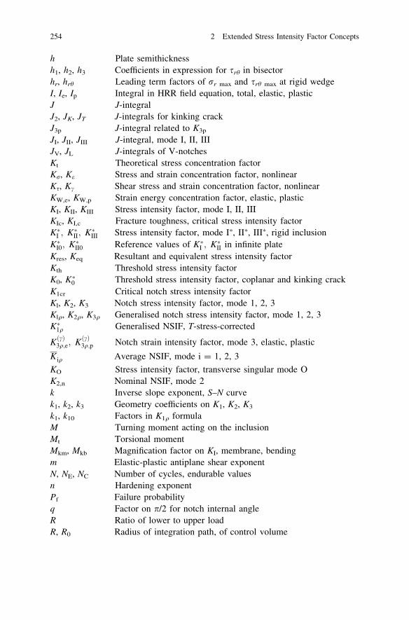
h Plate semithicknessh1, h2, h3 Coefficients in expression for srh in bisectorhr, hrh Leading term factors of rr max and srh max at rigid wedgeI, Ie, Ip Integral in HRR field equation, total, elastic, plasticJ J-integralJ2, JK, JT J-integrals for kinking crackJ3p J-integral related to K3p
JI, JII, JIII J-integral, mode I, II, IIIJV, JL J-integrals of V-notchesKt Theoretical stress concentration factorKr, Ke Stress and strain concentration factor, nonlinearKs, Kc Shear stress and strain concentration factor, nonlinearKW,e, KW,p Strain energy concentration factor, elastic, plasticKI, KII, KIII Stress intensity factor, mode I, II, IIIKIc, KI,c Fracture toughness, critical stress intensity factorK�I ; K�II; K�III Stress intensity factor, mode I*, II*, III*, rigid inclusionK�I0; K�II0 Reference values of K�I ; K�II in infinite plateKres, Keq Resultant and equivalent stress intensity factorKth Threshold stress intensity factorK0, K�0 Threshold stress intensity factor, coplanar and kinking crackK1cr Critical notch stress intensity factorKl, K2, K3 Notch stress intensity factor, mode 1, 2, 3Klq, K2q, K3q Generalised notch stress intensity factor, mode 1, 2, 3K�1q Generalised NSIF, T-stress-corrected
KðcÞ3q;e; KðcÞ3q;p Notch strain intensity factor, mode 3, elastic, plastic
K iq Average NSIF, mode i = 1, 2, 3
KO Stress intensity factor, transverse singular mode OK2,n Nominal NSIF, mode 2k Inverse slope exponent, S–N curvek1, k2, k3 Geometry coefficients on K1, K2, K3
k1, k10 Factors in K1q formulaM Turning moment acting on the inclusionMt Torsional momentMkm, Mkb Magnification factor on KI, membrane, bendingm Elastic-plastic antiplane shear exponentN, NE, NC Number of cycles, endurable valuesn Hardening exponentPf Failure probabilityq Factor on p/2 for notch internal angleR Ratio of lower to upper loadR, R0 Radius of integration path, of control volume
254 2 Extended Stress Intensity Factor Concepts

Rg, Rn Radius of gross and net cross-sectionRp Radius of plastic zoner Polar coordinate, radial distancer� Radius of core regionr0 Notch root distancer0, r1, r2 Radial distances in bipolar coordinate systemr2 V-notch radius at rhombic cut-outrp Radius of plastic zoneS S-stress, non-singularSmin, Smax Strain energy density factorss Elastic-plastic eigenvalue exponentsij Deviatoric stress tensorsc,p Elastic-plastic strain eigenvalue exponentT T-stress, non-singularTx, Ty, Tz Forces acting on rigid inclusionTr, TN Scatter range indices related to r and Nt, tu, tl Plate thickness, upper and loweru, v, w Displacements in Cartesian coordinatesu0, v0 Remote boundary displacementsux, uy, uz Displacements in Cartesian coordinatesui, ~ui Displacement vector, its angle-dependent termW, We, Wp Strain energy density, total, elastic, plasticW ; We; Wp Locally averaged strain energy densitiesWn,n Strain energy density of nominal stress in net cross-sectionw Complex coordinatex, y, z Cartesian coordinatesxp Extension of plastic zoneY1, Y2, Y3 Geometry factors on KI, KII, KIII
Ym, Yb Geometry factors on KI, membrane, bendingz Complex coordinatez Elastic-plastic eigenvalue exponenta Factor in normalised Ramberg–Osgood material lawa, a02 Notch opening semi-angleb Angle of inclination against bar axisb Notch angle dependent parameter in Neuber rule for V-notchc Internal semi-angle of V-notchc, ce, cp Total, elastic and plastic shear strainc0 Substitute or reference yield shear straincmax,p Maximal notch shear strain, nonlinearcp,eq Equivalent plastic shear straincY Yield limit shear strain, marked and offsetD Relative deviationd Thickness ratio
List of Symbols 255

d Factor in reduced Ramberg–Osgood material lawdij Kronecker deltae, ee, ep Total, elastic and plastic straineij, ~eij Strain tensor, its angle-dependent termek, ekH Maximum notch strain, nonlinear and Hookeen, enH Nominal strain, nonlinear and Hookeep, eq Equivalent plastic straine0 Substitute or reference yield straineY, eY0.2 Yield limit strain, marked and 0.2 % offsetf Complex coordinateg Factor on q for averaging Kiq
h, �h Polar angle, crack propagation angleh0, h1, h2 Polar angles in bipolar coordinate systemj Stiffness parameter in plate theoryj In-plane multiaxiality parameterk1, k2, k3 Eigenvalues at V-notch, mode 1, 2, 3k�1; k�2; k�3 Eigenvalues at rigid wedge, mode 1*, 2*, 3*
ka, ks Eigenvalues, antimetric and symmetric, antiplane shearkO Eigenvalue of transverse singular model Exponent in complex stress functionm Poisson’s ratioq Radius of notch curvature, notch radiusq� Microstructural support lengthr, r0, rx? Remote tensile stressr0 Substitute or reference yield stressr�0 Normal stress parallel to crack frontr0x, r0y, r0z Remote boundary stresses, mode 0I* loadingr1 First principal stressrcb, rtb Counter-bending and tensile-bending stressrE, rE Endurance limit stress, original and averagedre, req Effective and equivalent stress, von Mises~re Angle-dependent term of re
rh Hydrostatic stressrij, ~rij Stress tensor, its angle-dependent termrk, rkH Maximum notch stress, nonlinear and Hookerm, rb Membrane and bending stressrmax, rh max Maximum notch stressrn, rn,g, rn,n Nominal stress, in gross and net cross-sectionrn1, rn2 Endurable nominal stressrnE Endurance limit nominal stressrp Peak stressrr, rh Normal stresses in polar coordinatesrt, rt max Tangential stress, its maximum value
256 2 Extended Stress Intensity Factor Concepts
rth Threshold stress of crack propagationru, rl Stress in upper and lower platerx, ry, rz Normal stresses in Cartesian coordinatesrY, rY0.2 Yield limit, marked and 0.2 % offsetrI, rII, sIII Stresses related to mode I, II, IIIrk Slit-parallel stresss Resultant shear stress, antiplanes0 Substitute or reference yield shear stresss0, s�0 Remote shear stress, in-plane and out-of-planes1 Principal shear stresssE, �sE Endurance limit shear stress, original and averagedseq Equivalent or resultant shear stresssmax, s�max Maximum notch shear stress, in-plane and out-of-planesmax,p Maximum notch shear stress, nonlinear or plasticsn, s�n Nominal shear stress, in-plane and out-of-planesn,g, sn,n Nominal shear stress, gross and net cross-sections�n;g Nominal torsional stress, gross cross-section
srh Shear stress in polar coordinatessrz, shz Out-of-plane shear stressessY Shear yield limit, marked or offsets?, sk Shear stresses, transverse and longitudinal to edgeU Elliptical integral, stress resultant functionu, u* Complex stress functionv Trigonometric eigenvalue coefficientw Complex stress or harmonic displacement functionx, x1 Notch angle dependent parameter in K3q
~x1; ~x2 Auxiliary parameter in K1q, K2q
FE Finite elementFEM Finite element methodHRR Hutchinson–Rice–RosengrenNSIF Notch stress intensity factorSCF Stress concentration factorSIF Stress intensity factor
References
Akin JE (1976) The generation of elements with singularities. Int J Numer Meth Engng10:1249–1259
Anderson TL (21995) Fracture mechanics – Fundamentals and applications. CRC-Press, BocaRaton Fla
Atzori B (1985) Fracture mechanics or notch effect for fatigue design (in Italian). In: Proc 13thAIAS Conf, Bergamo, pp 294–307
List of Symbols 257
Atzori B, Meneghetti G (2001) Fatigue strength of fillet welded structural steels – finite elements,strain gauges and reality. Int J Fatigue 23:713–721
Atzori B, Lazzarin P, Tovo R (1997) Stress distribution for V-shaped notches under tensile andbending loads. Fatigue Fract Engng Mater Struct 20:1083–1092
Atzori B, Lazzarin P, Tovo R (1999(1)) From a local stress approach to fracture mechanics:a comprehensive evaluation of the fatigue strength of welded joints. Fatigue Fract EngngMater Struct 22:369–381
Atzori B, Lazzarin P, Tovo R (1999(2)) Stress field parameters to predict the fatigue strength ofnotched components. J Strain Analysis 34:437–453
Atzori B, Lazzarin P, Filippi S (2001) Crack and notches: analogies and differences of therelevant stress distributions and practical consequences in fatigue limit predictions. Int JFatigue 23:355–362
Ayatollahi MR, Dehghany M (2010) On T-stresses and V-notches. Int J Fract 165:1–126Ayatollahi MR, Nejati M (2011) Determination of NSIFs and coefficients of higher order terms
for sharp notches using finite element method. Int J Mech Sciences 53:64–177Benthem JP (1977) State of stress at the vertex of a quarter-infinite plate in a half space. Int J
Solids Struct 13:479–492Benthem JP (1987) Stresses in the region of rounded corners. Int J Solids Struct 23:239–252Berto F, Lazzarin P (2010) On higher order terms in the crack tip stress field. Int J Fract
161:221–226Berto F, Lazzarin P, Kotousov A, Harding S (2011) Out-of-plane singular stress fields in V-
notched plates and welded lap joints induced by in-plane shear load conditions. Fatigue FractEngng Mater Struct 34:291–304
Bogy DB (1971) Two edge-bonded elastic wedges of different materials and wedge angles undersurface tractions. J Appl Mech 38:377–386
Boukharouba T, Tamine T, Nui L, Chehimi C, Pluvinage G (1995) The use of notch intensityfactor as a fatigue crack initiation parameter. Engng Fract Mech 52:503–512
Brussat TB, Westermann RA (1975) A Westergaard-type stress function for line inclusionproblems. Int J Solids Struct 11:665–667
Carpenter WC (1984) Calculation of fracture mechanics parameters for a general corner. Int JFract 24:45–58
Chakrabarty J (32006) Theory of plasticity. Oxford, ElsevierChen DH (1995) Stress intensity factors for V-notched strip under tension or in-plane bending. Int
J Fract 70:81–97Chen DH, Ushijima K (2000) Elastic-plastic stress singularity near the tip of V-notch. Int J Fract
106:117–134Chen YZ (1986) Singular behaviour at fixed line tip in plane elasticity. Engng Fract Mech
25:11–16Chen YZ (1991) Investigation of stress singularity coefficient for a finite plate containing rigid
line. Engng Fract Mech 40:17–24Chen YZ (1992) Evaluation of stress singularity coefficient from the solution of the notch
problem. Comput Struct 42:563–567Chen YZ, Cheung YK (1987) Stress singularity coefficients in an infinite plate containing rigid
line and applied by concentrated forces. Engng Fract Mech 26:729–739Cheng YZ (1988) Evaluation of K2 values from the solution of notch problem. Int J Fract
38:R61–R64Cheung YK, Chen YZ (1989) Multiple rigid line problems in an infinite plate. Engng Fract Mech
34:379–391Cottrell B, Rice JR (1980) Slightly curved or kinked cracks. Int J Fract 16:155–169Creager M, Paris PC (1967) Elastic field equations for blunt cracks with reference to stress
corrosion cracking. Int J Fract Mech 3:247–252Dini D, Hills DA (2004) Asymptotic characterisation of nearly sharp notch root stress fields. Int J
Fatigue 130:651–666.
258 2 Extended Stress Intensity Factor Concepts

Dowling NE (1993) Mechanical behaviour of materials. Prentice Hall, New JerseyDunn ML, Suwito W, Cunningham S (1997(1)) Stress intensities at notch singularities. Engng
Fract Mech 57:417–430Dunn ML, Suwito W, Cunningham S (1997(2)) Fracture initiation at sharp notches: correlation
using critical stress intensities. Int J Solid Struct 34:3873–3883El Haddad MH, Topper TH, Smith KN (1979) Prediction of non-propagating cracks. Engng Fract
Mech 11:573–584Elber W (1970) Fatigue crack closure under cyclic tension. Engng Fract Mech 2:37–45Elber W (1971) The significance of fatigue crack closure. ASTM STP 486, Philadelphia Pa,
pp 230–242Erdogan F, Sih GC (1963) On the crack extension in plates under plane loading and transverse
shear. J Basic Engng 85:519–527Eurocode 3 (2005) Design of steel structures, Part 1-9, Fatigue, EN 1993-1-9, Brussels, CENFilippi S, Lazzarin P (2004) Distributions of the elastic principal stress due to notches in finite
size plates and rounded bars uniaxially loaded. Int J Fatigue 26:377–391Filippi S, Ciavarella M, Lazzarin P (2002(1)) An approximate, analytical approach to the ‘HRR’-
solution for sharp V-notches. Int J Fract 117:269–286Filippi S, Lazzarin P, Tovo R (2002(2)) Developments of some explicit formulas useful to
describe elastic stress fields ahead of notches in plates. Int J Solids Struct 39:4543–4565Gdoutos EE (1990) Fracture mechanics criteria and applications. Kluwer Acad Publ, DordrechtGlinka G (1985) Energy density approach to calculation of inelastic strain–stress near notches
and cracks. Engng Fract Mech 22:485–508Glinka G, Molski K (1981) A method of elastic-plastic stress and strain calculation at a notch
root. Mater Sci Engng 50:93–100Glinka G, Newport A (1987) Universal features of elastic notch tip stress fields. Int J Fatigue
9:143–150Gough HJ (1950) Engineering steels under combined cyclic and static stresses. J Appl Mech
50:113–125Gough HJ, Pollard HV (1935) The strength of metals under combined alternating stresses. In:
Proc Inst Mech Eng 131:3–103Gough HJ, Pollard HV (1937) Properties of some materials for cast crankshafts with special
reference to combined stresses. In: Proc Inst Automob Eng 31:821Gross R, Mendelson A (1972) Plane elastostatic analysis of V-notched plates. Int J Fract Mech
8:267–276Gross D, Seelig T (32001) Bruchmechanik. Springer Verlag, BerlinHaefele PM, Lee JD (1995) The constant stress term. Engng Fract Mech 50:869–882Hahn HG (1976) Bruchmechanik. Teubner, StuttgartHarding S, Kotousov A, Lazzarin P, Berto F (2010) Transverse singular effects in V-shaped
notches stressed in mode II. Int J Fract 164:1–14Hasebe N, Kutanda Y (1978) Calculation of stress intensity factors from stress concentration
factors. Engng Fract Mech 10:215–221Hasebe N, Nakamura T, Iida J (1990) Notch mechanics for plane and thin-plate bending
problems. Engng Fract Mech 37:87–99Hein VL, Erdogan F (1971) Stress singularities in a two-material wedge. Int J Fract Mech
7:317–330Hencky H (1924) Zur Theorie plastischer Deformationen und der hierdurch im Material
hervorgerufenen Nachspannungen. Z Angew Math Mech 4:323–334Hilton PD (1973) Plastic intensity factors for cracked plates subjected to biaxial loading. Int J
Fract 9:149–156Hilton PD, Hutchinson JW (1971) Plastic intensity factors for cracked plates. Engng Fract Mech
3:435–451Hobbacher A (ed) (2009) Fatigue design of welded joints and components. IIW-Doc XIII-2151-
07/XV-1254-07. Welding Research Council, Bulletin 520, New York
References 259

Hui CY, Ruina A (1995) Why K? Higher order singularities and small-scale yielding. Int J Fract72:97–120
Hult JA, McClintock FA (1956) Elastic-plastic stress and strain distribution around sharp notchesunder repeated shear. In: 9th Int Congress Appl Mech, 8, Brussels
Hussain MA, Pu SL, Underwood J (1974) Strain energy release rate for a crack under combinedmode I and mode II. In: Fracture analysis, ASTM STP 560, Philadelphia Pa, pp 2–28
Hutchinson JW (1968) Singular behaviour at the end of a tensile crack tip in a hardening material.J Mech Phys Solids 16:13–31
Irwin GR (1957) Analysis of stresses and strains near the end of a crack traversing a plate. J ApplMech 24:361–364
Irwin GR (1958) Fracture. In: Handbuch der Physik, Vol 4, pp 551–590. Springer, BerlinKane TR, Mindlin RD (1956) High frequency extensional vibrations of plates. J Appl Mech
23:277–283Kirsch G (1898) Die Theorie der Elasitzität und die Bedürfnisse der Festigkeitslehre. Z VDI
42:797–807Koibuchi K, To K, Iida M, Hosomi T (1999) Fatigue strength assessment of welded toes and
defects of structures based on cyclic plastic zone size. In: Engng Against Fatigue. Rotterdam,Balkema, pp 373–380
Kotousov A (2005) On stress singularities at angular corners of plates of arbitrary thickness undertension. Int J Fract 132:L29–L36
Kotousov A (2007) Fracture in plates of finite thickness. Int J Solids Struct 44:8259–8273Kotousov A, Lew YT (2006) Stress singularities resulting from various boundary conditions in
angular corners of plates of arbitrary thickness in extension. Int J Solids Struct 43:5100–5109Kotousov A, Wang CH (2002) Three-dimensional solutions for transversally isotropic composite
plates with a notch. Compos Struct 57:443–450Kuang ZB, Xu XP (1987) Stress and strain fields at the tip of a V-notch in a power law hardening
material. Int J Fract 35:39–53Kullmer G (1992) Elastic stress fields in the vicinity of a narrow notch with circular root. In: Proc
Eur Conf on Reliability and Structural Integrity of Advanced Materials, ECF9, pp 905–910Kurath P (1992) Multiaxiality fatigue criteria for spot welds. SAE Techn Paper 920668, SAE.
Warrendale PaLarsson SG, Carlsson AJ (1973) Influence of non-singular stress terms and specimen geometry on
small-scale yielding at crack tips in elastic-plastic materials. J Mech Phys Solids 21:263–277Lazzarin P (1986) Influence of welded joint geometry on stress fields in the highly stressed zones
(in Italian). Riv Ital Saldatura 2:107–115Lazzarin P, Filippi S (2006) A generalized stress intensity factor to be applied to rounded
V-shaped notches. Int J Solids Struct 43:2461–2478Lazzarin P, Livieri P (2000) Plastic zone size at the weld toe in welded joints made of steel and
light metals (in Italian). Rev Ital Della Saldatura 52:421–437Lazzarin P, Livieri P (2001) Notch stress intensity factors and fatigue strength of aluminium and
steel welded joints. Int J Fatigue 23:225–232Lazzarin P, Tovo R (1996) A unified approach to the evaluation of linear-elastic stress fields in
the neighbourhood of cracks and notches. Int J Fract 78:3–19Lazzarin P, Tovo R (1998) A notch stress intensity factor approach to the stress analysis of welds.
Fatigue Fract Engng Mater Struct 21:1089–1103Lazzarin P, Zambardi R (2002) The equivalent strain energy density approach reformulated and
applied to sharp V-shaped notches under localized and generalized plasticity. Fatigue FractEngng Mater Struct 25:917–928
Lazzarin P, Zappalorto M (2008) Plastic notch stress intensity factors for pointed V-notchesunder antiplane shear loading. Int J Fract 152:1–25
Lazzarin P, Tovo R, Meneghetti G (1997) Fatigue crack initiation and propagation phases nearnotches in metals with low notch sensitivity. Int J Fatigue 19:647–657
Lazzarin P, Tovo R, Filippi S (1998) Elastic stress distributions in finite size plates with edgenotches. Int J Fract 91:269–282
260 2 Extended Stress Intensity Factor Concepts

Lazzarin P, Zambardi R, Livieri P (2001) Plastic notch stress intensity factors for large V-shapednotches under mixed mode load conditions. Int J Fract 107:361–377
Lazzarin P, Livieri P, Zambardi R (2002) A J-integral based approach to predict the fatiguestrength of components weakened by sharp V-shaped notches. Int J Comp Appl Techn15:202–210
Lazzarin P, Sonsino CM, Zambardi R (2004) A notch stress intensity approach to assess themultiaxial fatigue strength of welded tube-to-flange joints subjected to combined loadings.Fatigue Fract Engng Mater Struct 27:127–140
Lazzarin P, Berto F, Radaj D (2006) Uniform fatigue strength of butt and fillet welded joints interms of local strain energy density. In: Proc 9th Int Fatigue Congress. Oxford, ElsevierScience, pp 1–10
Lazzarin P, Zappalorto M, Yates JR (2007) Analytical study of stress distributions due to semi-elliptic notches in shafts under torsion loading. Int J Engng Sci 45:308–328
Lazzarin P, Berto F, Radaj D (2009) Fatigue-relevant stress field parameters of welded lap joints– Pointed slit tip compared with keyhole notch. Fatigue Fract Engng Mat Struct 32:713–735
Lazzarin P, Zappalorto M, Berto F (2011) Generalized stress intensity factors for rounded notchesin plates under in-plane shear loading. Int J Fract 170:123–144
Lee H, Kim N (2004) Fatigue life prediction of multi-spot welded panel structures using anequivalent stress intensity factor. Int J Fatigue 26:403–412
Lin KY, Tong P (1980) Singular finite elements for the fracture analysis of V-notched plate. Int JNumer Meth Engng 15:1343–1354
Linder J, Melander A, Larsson M, Bergengren Y (1998) Fatigue design of spot-welded austeniticand duplex stainless sheet steels. Fatigue Fract Engng Mater Struct 21:673–686
Livieri P, Tovo R (2009) The use of the JV parameter in welded joints – Stress analysis andfatigue assessment. Int J Fatigue 31:153–163
Meneghetti G, Lazzarin P (2007) Significance of the elastic peak stress evaluated by FE analysesat the point of singularity of sharp V-notched components. Fatigue Fract Engng Mater Struct30:95–106
Mizui M, Sekine T, Tsujimura A, Takishima T, Shimazaki Y (1988) An evaluation of fatiguestrength for various kinds of spot-welded specimens. SAE Techn Paper 880375, SAE,Warrendale Pa
Mura T (1987) Micromechanics of defects in solids. Nijhoff, DordrechtMurakami Y (ed) (1987) Stress intensity factors handbook. Pergamon Press, OxfordMushkelishvili NI (1963) Some basic problems of the mathematical theory of elasticity.
Noordhoff, Groningen.Nakamura T, Parks DM (1989) Antisymmetrical 3d stress field near the crack front of a thin
elastic plate. Int J Solids Struct 25:1411–1426Neuber H (21958, 31985) Kerbspannungslehre. Springer Verlag, BerlinNeuber H (1961) Theory of stress concentration for shear-strained prismatical bodies with
arbitrary nonlinear stress–strain law. J Appl Mech 28:544–550Neuber H (1968(1)) A physically nonlinear notch and crack model. J Mech Phys Solids
16:289–294Neuber H (1968(2)) Über die Berücksichtigung der Spannungskonzentration bei Festigkeitsber-
echnungen. Konstruktion 20:245–251Noda NA, Nisitani H, Harada S, Takase Y (1995) Fatigue strength of notched specimens having
nearly equal sizes of ferrite. Int J Fatigue 17:237–244Noda NA, Oda K, Inoue T (1996) Analysis of newly defined stress intensity factors for angular
corners using singular integral equations of the body force method. Int J Fract 76:243–261Noda NA, Takase Y (2003) Generalised stress intensity factors for V-shaped notch in a round bar
under torsion, tension and bending. Engng Fract Mech 70:1447–1466Nui LS, Chehimi C, Pluvinage G (1994) Stress field near a large blunted tip V-notch and
application of the concept of the critical notch stress intensity factor (NSIF) to the fracturetoughness of very brittle materials. Engng Fract Mech 49: 235–335
References 261

Pook LP (1989) The significance of mode I branch cracks for mixed mode fatigue crack growththreshold behaviour. In: Brown MW, Miller KJ (eds) Biaxial and multiaxial fatigue. MechEngng Publ, London, pp 247–263
Quian J, Hasebe N (1997) Property of eigenvalues and eigenfunctions for an interface V-notch inantiplane elasticity. Engng Fract Mech 56:729–734
Radaj D (1971) Kerbspannungen an Öffnungen und starren Kernen. Habilitation thesis, TUBraunschweig, self-publishing
Radaj D (1989) Stress singularity, notch stress and structural stress at spot-welded joints. EngngFract Mech 34:495–506
Radaj D (2010) T-stress corrected notch stress intensity factors with application to welded lapjoints. Fatigue Fract Engng Mater Struct 33:378–389
Radaj D, Giering A (1994) Spot-welded H-specimen – The local stress parameters. Materialprüf36:275–281
Radaj D, Giering A (1995) Spot-welded double-cup specimen – The local stress parameters.Materialprüf 37:458–462; emendation 39:430
Radaj D, Heib M (1978) Energy density fracture criteria for cracks under mixed-mode loading.Materialprüf 20:256–262
Radaj D, Schilberth G (1977) Kerbspannungen an Ausschnitten und Einschlüssen. DVS-Verlag,Düsseldorf
Radaj D, Vormwald M (32007) Ermüdungsfestigkeit – Grundlagen für Ingenieure. SpringerVerlag, Berlin
Radaj D, Zhang S (1991(1)) Stress intensity factors for spot welds between plates of unequalthickness. Engng Fract Mech 39:391–413
Radaj D, Zhang S (1991(2)) Simplified formulae for stress intensity factors of spot welds. EngngFract Mech 40:233–236
Radaj D, Zhang S (1992) Stress intensity factors for spot welds between plates of dissimilarmaterials. Engng Fract Mech 42:407–426
Radaj D, Zhang S (1993(1)) Analogies between crack tip and rigid line tip stresses anddisplacements. Engng Fract Mech 44:913–919
Radaj D, Zhang S (1993(2)) Loading modes and stress intensity factors at rigid layer edges. EngngFract Mech 46:199–208
Radaj D, Zhang S (1993(3)) On the relations between notch stress and crack stress intensity inplane shear and mixed-mode loading. Engng Fract Mech 44:691–704
Radaj D, Zhang S (1994). Stress distribution at bimaterial crack tips. Engng Fract Mech47:613–617
Radaj D, Zhang S (1995(1)). Process zone fracture criteria for crack tips. Engng Fract Mech50:111–120
Radaj D, Zhang S (1995(2)) Punktgeschweißte Doppelhutprofilprobe unter Torsionsbelastung –lokale Beanspruchungsparameter und Schwingfestigkeit. Materialprüf 37:458–462; emenda-tion 39:426
Radaj D, Zheng Z, Möhrmann W (1990) Local stress parameters at the weld spot of variousspecimens. Engng Fract Mech 37:933–951
Radaj D, Lehrke HP, Greuling S (2001) Theoretical fatigue-effective notch stresses at spot welds.Fatigue Fract Engng Mater Struct 24:293–308
Radaj D, Sonsino CM, Fricke W (22006) Fatigue assessment of welded joints by localapproaches. Woodhead Publ, Cambridge and CRC Press, Boca Raton Fla
Radaj D, Berto F, Lazzarin P (2009) Local fatigue strength parameters for welded joints based onstrain energy density with inclusion of small-size notches. Engng Fract Mech 76:1109–1130
Rice JR (1967) Stresses due to a sharp notch in a work-hardening elastic-plastic material loadedby longitudinal shear. J Appl Mech 34:287–298
Rice JR (1968) A path-independent integral and the approximate analysis of strain concentrationby notches and cracks. J Appl Mech 35:379–386
Rice JR, Rosengren GF (1968) Plane strain deformation near a crack tip in a power-lawhardening material. J Mech Phys Solids 16:1–12
262 2 Extended Stress Intensity Factor Concepts

Rooke DP, Cartwright DJ (1976) Compendium of stress intensity factors. Her Majesty’sStationary Office, London
Sanford RJ (2003) Principles of fracture mechanics. Pearson Education, Upper Saddle River, NJSator C (2010) Asymptotische Nahfeldanalyse ebener Multi-Materialverbindungsstellen mit der
Methode der komplexen Potentiale. TU Darmstadt, Forschungsbericht Mechanik, Bd. 21Savruk MP, Kazberuk A (2006) Relationship between the stress intensity and stress concentration
factors for sharp and rounded notches. Mater Sci 42:725–738Savruk MP, Kazberuk A (2007) A unified approach to problems of stress concentration near
V-shaped notches with sharp and rounded tip. Int J Appl Mech 43:182–197Savruk MP, Kazberuk A (2010) Two-dimenstional fracture mechanics problems for solids with
sharp and rounded V-notches. Int J Fract 161:79–95Seeger T, Greuling S, Brüning J, Leis P, Radaj D, Sonsino CM (2005) Bewertung lokaler
Berechnungskonzepte zur Ermüdungsfestigkeit von Punktschweißverbindungen. FAT-Schrif-tenreihe 196, Frankfurt
Seweryn A (2002) Modeling of singular stress fields using the finite element method. Int J SolidsStruct 39:4787–4804
Seweryn A, Molski K (1996) Elastic stress singularities and corresponding generalised stressintensity factors for angular corners under various boundary conditions. Engng Fract Mech55:529–556
Seweryn A, Mróz Z (1995) A non-local stress failure condition for structural elements undermultiaxial loading. Engng Fract Mech 51:855–973
Seweryn A, Zwolinski J (1993) Solution for the stress and displacement fields in the vicinity ofa V-notch of negative wedge angles in plane problems of elasticity. Engng Fract Mech44:275–281
Sherry AH, France CC, Goldthorpe MR (1995) Compendium of T-stress solutions for two- andthree-dimensional cracked geometries. Fatigue Fract Engng Mater Struct 18:141–155
Shlyannikov VN, Boychenko NV, Tartygasheva AM (2011) In-plane and out-of-plane crack tipconstraint effects under biaxial nonlinear deformation. Engng Fract Mech 78:1771–1783
Sih GC (1965) Plane extension of rigidly embedded line inclusions. In: Huang TC, Johnson MW(eds) Developments in mechanics, vol 3. John Wiley, London, pp 61–79
Sih GC (1973) Handbook of stress intensity factors. Lehigh Univ, Bethlehem PaSih GC (1974) Strain energy density factor applied to mixed-mode crack problems. Int J Fract
10:305–321Sih GC (1975) A three-dimensional strain energy density factor theory of crack propagation. In:
Three-dimensional crack problems. Leyden, Noordhoff, pp 15–80Sih GC, Liebowitz H (1968) Mathematical theories of brittle fracture. In: Fracture, vol. 2,
Mathematical fundamentals. Academic PressSmith E (2004) The elastic stress distribution near the root of an elliptically cylindrical notch
subjected to mode III loadings. Int J Engng Sci 42:1831–1839Smith E (2006) The mode III elastic stress distribution near the root of an intrusion-type notch
and of a keyhole notch. Int J Engng Sci 44:340–344Sneddon IN (1946) The distribution of stress in the neighbourhood of a crack in an elastic solid.
Proc Roy Soc, Ser A 187:229–260Susmel L, Tovo R (2004) Multiaxial fatigue life prediction of two welded details subjected to
local complex stress states. In: Proc 7th Int Conf on Biaxial/Multiaxial Fatigue and Fracture.Berlin, DVM, pp 447–452
Tada HP, Paris C, Irwin GR (1973) The stress analysis of cracks handbook. Del Res Corp,Hellertown Pa
Tada HP, Paris C, Irwin GR (31999) The stress analysis of cracks handbook. ASME Press,New York
Tanaka K, Okajima H, Koibuchi K (2002) Fatigue strength CAE system for three-dimensionalwelded structures. Fatigue Fract Engng Mater Struct 25:275–282
Theocaris PS, Ioakimidis NT (1979) The V-notched elastic half plane problem. Acta Mech32:125–140
References 263

Tovo R, Lazzarin P (1999) Relationships between local and structural stress in the evaluation ofthe weld toe stress distribution. Int J Fatigue 21:1063–1078
Unger DJ (2001) Analytical fracture mechanics. Dover Publ, Mineola, NYUnger DJ (2005) A plane stress perfectly plastic mode I crack solution with continuous stress
field. J Appl Mech 72:62–67Unger DJ (2007) A complete perfectly plastic solution for the mode I crack problem under plane
stress loading conditions. J Appl Mech 74:586–589Verreman Y, Nie B (1996) Early development of fatigue cracking at manual fillet welds. Fatigue
Fract Engng Mater Struct 19:669–681Verreman Y, Nie B (1997) Short crack fatigue propagation at fillet welds. In: Proc Int Conf on
Performance of Dynamically Loaded Welded Structures. New York, WRC, pp 240–253Wang TJ, Kuang ZB (1999) Higher order aymptotic solutions of V-notch tip fields for damaged
nonlinear materials under antiplane shear loading. Int J Fract 96:303–329Wang ZY, Zhang HT, Chou YT (1985) Characteristics of the elastic field of a rigid line
inhomogeneity. J Appl Mech 52:818–822Wang ZY, Zhang HT, Chou YT (1986) Stress singularity at the tip of a rigid line inhomogeneity
under antiplane shear loading. J Appl Mech 53:459–461Westergaard HM (1939) Bearing pressures and cracks. J Appl Mech 6:A49–A53Williams ML (1952) Stress singularities resulting from various boundary conditions in angular
corners of plates in tension. J Appl Mech 19:526–528Williams ML (1957) On the stress distribution at the base of a stationary crack. J Appl Mech
24:109–114Williams JG, Ewing PD (1972) Fracture under complex stress – The angled crack problem. Int J
Fract Mech 8:441–446Yao W, Xia K, Gu Y (1995) On the fatigue notch factor Kf. Int J Fatigue 17:245–251Yang W, Freund LB (1985) Transverse shear effects for through-cracks in an elastic plate. Int J
Solids Struct 21:977–994Yang S, Yuan FG, Cai X (1996) Higher order asymptotic elastic-plastic crack tip fields under
antiplane shear. Engng Fract Mech 54:405–422Yuan FG, Yang S (1994/95) Analytical solutions of fully plastic crack tip higher order fields
under antiplane shear. Int J Fract 69:1–26Yuuki R, Ohira T (1986) Fracture mechanics analysis of the fatigue strength of various spot-
welded joints. Seisan Kenyu 38:475–478Yuuki R, Ohira T (1989) Development of the method to evaluate the fatigue life of spot-welded
structures by fracture mechanics. IIW Doc III-928-89/XIII-1358-89Yuuki R, Ohira T, Kishi N, Mori N (1985(1)) Fracture mechanics evaluating of the fatigue
strength of spot-welded joints and structures. JSAE Paper 852096, pp 501–506Yuuki R, Ohira T, Nakatsukasa H, Li W (1985(2)) Fracture mechanics analysis and evaluation of
the fatigue strength of spot-welded joints (in Japanese). Trans JSME 51:1772–1779Zappalorto M, Lazzarin P (2007) Analytical study of the elastic-plastic stress fields ahead of
parabolic notches under antiplane shear loading. Int J Fract 148:139–154Zappalorto M, Lazzarin P (2009) A new version of the Neuber rule accounting for the influence
of the notch opening angle for out-of-plane shear loads. Int J Solids Struct 46:1901–1910Zappalorto M, Lazzarin P (2010) A unified approach to the analysis of nonlinear stress and strain
fields ahead of mode III loaded notches and cracks. Int J Solids Struct 47:851–864Zappalorto M, Lazzarin P (2011(1)) In-plane and out-of-plane stress field solutions for V-notches
with end holes. Int J Fract 168:167–180Zappalorto M, Lazzarin P (2011(2)) Strain energy based evaluations of plastic notch stress
intensity factors at pointed V-notches under tension. Engng Fract Mech 78:2691–2706Zappalorto M, Lazzarin P (2011(3)) Stress fields due to inclined notches and shoulder fillets in
shafts under torsion. J Strain Analysis 46:187–199Zappalorto M, Lazzarin P (2011(4)) On the intensity of linear-elastic high order singularities
ahead of cracks and re-entrant corners. Int J Solids Struct 48:953–961
264 2 Extended Stress Intensity Factor Concepts

Zappalorto M, Lazzarin P, Yates JR (2008) Elastic stress distributions resulting from hyperbolicand parabolic notches in round shafts under torsion and uniform antiplane shear loadings. Int JSolid Struct 45:4879–4901
Zappalorto M, Lazzarin P, Berto F (2009) Elastic notch stress intensity factors for sharplyV-notched rounded bars under torsion. Engng Fract Mech 76:439–453
Zappalorto M, Lazzarin P, Filippi S (2010) Stress field equations for U and blunt V-shapednotches in axisymmetric shafts under torsion. Int J Fract 164:253–269
Zhang S (1999) Recovery of notch stress and stress intensity factors. In: NAFEMS WorldCongress ‘99, Effective engineering analysis, vol. 2:1103–1114
References 265

http://www.springer.com/978-3-642-30739-3