Explosives Engineers’ Guide - Dyno Nobel/media/Files/Dyno/ResourceHub/Brochures... · of...
52
Explosives Engineers’ Guide
Transcript of Explosives Engineers’ Guide - Dyno Nobel/media/Files/Dyno/ResourceHub/Brochures... · of...

Explosives Engineers’ Guide

DISCLAIMER
The explosive products discussed in this document should only be handled by persons with the appropriate technical skills, training and licences. While Dyno Nobel has made every effort to ensure the information in this document is correct, every user is responsible for understanding the safe and correct use of the products. If you need specific technical advice or have any questions, you should contact your Dyno Nobel representative. This information is provided without any warranty, express or implied, regarding its correctness or accuracy and, to the maximum extent permitted by law, Dyno Nobel expressly disclaims any and all liability arising from the use of this document or the information contained herein. It is solely the responsibility of the user to make enquiries, obtain advice and determine the safe conditions for use of the products referred to herein and the user assumes liability for any loss, damage, expense or cost resulting from such use.
Dyno Nobel Asia Pacific Pty Limited (ACN 003 269 010) is a subsidiary of Incitec Pivot Limited (ACN 004 080 264) Level 8, 28 Freshwater Place, Southbank VIC 3006
® DYNO, GROUNDBREAKING PERFORMANCE, TITAN, POWERMITE, DYNOSPLIT, FIRELINE, SANFOLD, Z-BAR, NONEL, RiGHT, RINGPRIME, PRIMACORD, PRIMALINE, TROJAN, 9000XERO, POWERMITE PLUS & POWERMITE THERMO are registered trademarks of the Dyno Nobel / Incitec Pivot Limited Group.
SMARTSHOT, DRIFTSHOT, DIGISHOT and BLASTWEB are registered trademarks of DetNet South Africa (Pty) Limited.
™ BLAST HI-T, STINGER EXPLODER, STEMPAC, SUPER STARTER, DYNOSTART and DYNOTRACKER are trademarks of the Dyno Nobel / Incitec Pivot Group.
© Dyno Nobel Asia Pacific Pty Limited 2017. Reproduction without permission is strictly prohibited.
REF0168/0917/AZZAUS/1500

The information provided in this brochure is confidential. It may not be disclosed to any person without the express written consent of Dyno Nobel Asia Pacific Pty Limited.
You may only use this information if you are a customer of Dyno Nobel and you have been provided with it directly by an authorised representative of Dyno Nobel.

© Dyno Nobel Asia Pacific Pty Limited 2017. Reproduction without permission is strictly prohibited.
Rapid Hazard Assessment
Take 5!
• Is the task new?
• Is anything different?
• Has anything changed since you last performed this task?
• If so, STOP, THINK and apply the Take 5 steps!
1 Describe the task. What is the task you are about to do?
2 List the Hazards. What are the main hazards involved in carrying
out the task?
3 List the controls. What controls will you use to reduce
the risk?
4 Assess the risk. Use the Hazard Assessment Tool (HAT) to
determine the risk after controls are applied.
5 Decide what is next. Apply the controls.
Is it safe to proceed with the task? Are additional controls required?

headline
© Dyno Nobel Asia Pacific Pty Limited 2017. Reproduction without permission is strictly prohibited.
Airblast Airborne shock wave resulting from the detonation of explosives.
Back break Rock broken beyond the limits of the last row.
Blasthole pressure The pressure which the gasses of detonation exert on the blasthole wall.
Burden The distance between adjacent rows.
Charge weight The amount of explosive charge in kilograms.
Column charge A continuous charge of explosives in a blasthole.
Critical diameter The minimum diameter for propagation of a stable detonation.
Cutoffs A portion of an explosive column that has failed to detonate due to rock movement.
Decoupling The use of explosive products having smaller volume than the volume of the blasthole it occupies.
Delay blasting The use of delay detonators or connectors to separate charges by a defined time.
Density Mass per unit volume.
Detonation pressure The pressure created in the reaction zone of a detonating explosive.
Explosive Any chemical or mixture of chemicals that can react to produce an explosion.
Free face A rock surface that provides the rock with room to expand when blasted.
Flyrock Rock that is propelled through air from a blast.
Fragmentation Measure to describe the size of distribution of broken rock after blasting.
Ground vibration Ground movement caused by the stress waves emanating from a blast.
Initiation The act of detonating explosives by any means.
Line drilling A method of overbreak control which uses a series of closely spaced holes that are not charged.
Loading density The weight of explosives per metre of blasthole.
Maximum Instantaneous Charge (MIC) Mass of explosive detonating in some defined time period, usually 8 milliseconds.
Overbreak Excessive breakage of rock beyond the desired excavation limit.
Particle velocity The speed of movement in a given direction of a rock or soil mass.
Pre-split A controlled blast in which decoupled charges are fired in holes on the perimeter of the excavation prior to the main firing.
Relative Bulk Strength (RBS) The energy yield per unit volume of an explosive compared to ANFO.
Relative Weight Strength (RWS) The energy yield per unit mass of an explosive compared to ANFO.
Spacing The distance between blastholes in the same row.
Stemming Inert material used to confine the gasses generated during detonation.
Swell factor The ratio of the volume of broken rock to the volume of in-situ rock.
Velocity of Detonation (VoD) The velocity at which a detonation progresses through an explosive.
Glossary

© Dyno Nobel Asia Pacific Pty Limited 2017. Reproduction without permission is strictly prohibited.
Blast design terminology and formulas
Hole length (L) = BH + SDCharge length (C) = L – SLBlast volume (V) = B x S x BH x NBlasted tonnes (T) = V x Density of rock in t/m3 Volume of blasthole (Vb) = π x D2/4000 x LMass of explosive per hole (kg) = Volume of hole length charged x Explosive densityPF (kg/m3) = Total explosives in the blast/blast volumePF (kg/t) = Total explosives in the blast/blasted tonnesRWS = AWS of explosive/AWS of ANFO x 100RBS = (RWS explosive x explosive density)/(ANFO density)Energy factor = PF x RWSVertical length of angled holes = Measured hole length x cos
Bench Height(BH)
Floor
Hole Length (L)
Subdrill (SD)
Toe Burden
Toe
Face Angle (FA)
Free Face
(C)ExplosiveColumnHeight
Stem Height (SL)
Drilled Burden (B) Drilled Spacing (S)
Hole Diameter (D)
Backbreak New Crest(After Mucking)
Crest Burden
Crest
= Angle subtended from the vertical by the inclined hole
π = 3.1416 (the ratio of the circumference of a circle to its diameter)
AWS = Absolute weight strengthB = Drilled burden (m)BH = Bench height (m)C = Explosive column height or charge
length (m) D = Hole diameter in millimetres
L = Hole length (m)N = Number of holes in a blastPF = Powder factorRBS = Relative bulk strengthRWS = Relative weight strengthS = Drilled spacing (m)SD = Subdrill (m)SL = Stemming length (m)T = Blasted tonnesV = Blast volume (m3)

© Dyno Nobel Asia Pacific Pty Limited 2017. Reproduction without permission is strictly prohibited.
These rules provide a first estimate in the absence of any better data.
Blasthole diameter in mm ≤ 15 x Bench height (BH) in metres
Bench height (BH) in metres ≥ (Blasthole diameter (D) in mm)/15
Burden (B) = (25 to 40) x (D)
Spacing (S) = 1.15 x B (This gives an equilateral pattern)
Subdrill = (3 to 15) x D
Charge length (C) ≥ 20 D
Stemming ≥ 20 x D or (0.7 – 1.2) x B
Burden stiffness ratio = BH/B : 2 to 3.5 good fragmentation
: > 3.5 very good fragmentation
Stemming material size = D/10 to D/20 (Angular material with minimum fines)
Presplit blastingSpacing = Hole diameter x 12
Burden = 0.5 x production blast burden (B)
Uncharged length at top = 10 x D
Powder factor = 0.5kg per square metre of face
Do not stem holes.
Fire all holes on the same delay, or in groups of ≥ 5 holes
Smooth BlastingSpacing = 15 x Hole diameter (hard rock)
20 x Hole diameter (soft rock)
Burden = 1.25 x Spacing
Fire as many holes as possible on one delay.
Stem holes.
Powder factors
Rules of thumb
Typical powder factors used in mass blastsRock type PF (kg/m3)Hard 0.7 – 0.8
Medium 0.4 – 0.5
Soft 0.25 – 0.35
Very Soft 0.15 – 0.25
Typical powder factors used in presplit and smooth blastingHole diameter PF (kg/m2)Hard 0.6 – 0.9
Medium 0.4 – 0.5
Soft 0.2 – 0.3
© Dyno Nobel Asia Pacific Pty Limited 2017. Reproduction without permission is strictly prohibited.
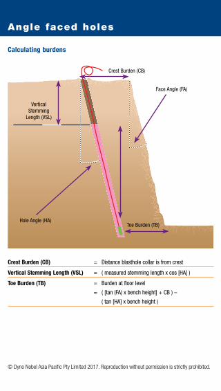
Calculating burdens
Crest Burden (CB) = Distance blasthole collar is from crest
Vertical Stemming Length (VSL) = ( measured stemming length x cos [HA] )
Toe Burden (TB) = Burden at floor level
= ( [tan (FA) x bench height] + CB ) –
( tan [HA] x bench height )
Angle faced holes
Vertical Stemming
Length (VSL)
Crest Burden (CB)
Hole Angle (HA)
Face Angle (FA)
Toe Burden (TB)

headline
© Dyno Nobel Asia Pacific Pty Limited 2017. Reproduction without permission is strictly prohibited.
Volume table
CUBI
C M
ETRE
S OF
ROC
K PE
R M
ETRE
OF
BLAS
THOL
EHO
LE B
URDE
N
SPAC
ING
(Met
res)
(Met
res)
1.00
1.
25
1.50
1.
75
2.00
2.
25
2.50
2.
75
3.00
3.
50
4.00
4.
50
5.00
6.
00
6.50
7.
00
7.50
8.
00
8.50
9.
00
9.50
10
.00
11.0
0 12
.00
1.00
1.
25
1.50
1.
75
2.00
2.
25
2.50
2.
75
3.00
3.
50
4.00
4.
50
1.00
1.25
1.
56
1.88
2.
19
2.50
2.
81
3.13
3.
44
3.75
4.
38
5.00
5.
63
6.25
1.25
1.50
1.
88
2.25
2.
63
3.00
3.
38
3.75
4.
13
4.50
5.
25
6.00
6.
75
7.50
9.
00
1.50
2.00
2.
50
3.00
3.
50
4.00
4.
50
5.00
5.
50
6.00
7.
00
8.00
9.
00
10.0
0 12
.00
13.0
0
2.00
2.25
2.
81
3.38
3.
94
4.50
5.
06
5.63
6.
19
6.75
7.
88
9.00
10
.13
11.2
5 13
.50
14.6
3 15
.75
2.25
2.50
3.
13
3.75
4.
38
5.00
5.
63
6.25
6.
88
7.50
8.
75
10.0
0 11
.25
12.5
0 15
.00
16.2
5 17
.50
18.7
5
2.50
2.75
3.
44
4.13
4.
81
5.50
6.
19
6.88
7.
56
8.25
9.
63
11.0
0 12
.38
13.7
5 16
.50
17.8
8 19
.25
20.6
3 22
.00
2.75
3.00
3.
75
4.50
5.
25
6.00
6.
75
7.50
8.
25
9.00
10
.50
12.0
0 13
.50
15.0
0 18
.00
19.5
0 21
.00
22.5
0 24
.00
5.50
3.00
4.
38
5.25
6.
13
7.00
7.
88
8.75
9.
63
10.5
0 12
.25
14.0
0 15
.75
17.5
0 21
.00
22.7
5 24
.50
26.2
5 28
.00
29.7
5 31
.50
3.50
5.
00
6.00
7.
00
8.00
9.
00
10.0
0 11
.00
12.0
0 14
.00
16.0
0 18
.00
20.0
0 24
.00
26.0
0 28
.00
30.0
0 32
.00
34.0
0 36
.00
38.0
0
4.00
5.
63
6.75
7.
88
9.00
10
.13
11.2
5 12
.38
13.5
0 15
.75
18.0
0 20
.25
22.5
0 27
.00
29.2
5 31
.50
33.7
5 36
.00
38.2
5 40
.50
42.7
5 45
.00
4.50
7.50
8.
75
10.0
0 11
.25
12.5
0 13
.75
15.0
0 17
.50
20.0
0 22
.50
25.0
0 30
.00
32.5
0 35
.00
37.5
0 40
.00
42.5
0 45
.00
47.5
0 50
.00
55.0
0
5.00
9.00
10
.50
12.0
0 13
.50
15.0
0 16
.50
18.0
0 21
.00
24.0
0 27
.00
30.0
0 36
.00
39.0
0 42
.00
45.0
0 48
.00
51.0
0 54
.00
57.0
0 60
.00
66.0
0 72
.00
6.00
11
.38
13.0
0 14
.63
16.2
5 17
.88
19.5
0 22
.75
26.0
0 29
.25
32.5
0 39
.00
42.2
5 45
.50
48.7
5 52
.00
55.2
5 58
.50
61.7
5 65
.00
71.5
0 78
.00
6.50
12
.25
14.0
0 15
.75
17.5
0 19
.25
21.0
0 24
.50
28.0
0 31
.50
35.0
0 42
.00
45.5
0 49
.00
52.5
0 56
.00
59.5
0 63
.00
66.5
0 70
.00
77.0
0 84
.00
7.00
13
.13
15.0
0 16
.88
18.7
5 20
.63
22.5
0 26
.25
30.0
0 33
.75
37.5
0 45
.00
48.7
5 52
.50
56.2
5 60
.00
63.7
5 67
.50
71.2
5 75
.00
82.5
0 90
.00
7.50
16.0
0 18
.00
20.0
0 22
.00
24.0
0 28
.00
32.0
0 36
.00
40.0
0 48
.00
52.0
0 56
.00
60.0
0 64
.00
68.0
0 72
.00
76.0
0 80
.00
88.0
0 96
.00
8.00
17.0
0 19
.13
21.2
5 23
.38
25.5
0 29
.75
34.0
0 38
.25
42.5
0 51
.00
55.2
5 59
.50
63.7
5 68
.00
72.2
5 76
.50
80.7
5 85
.00
93.5
0 10
2.00
8.
50
18.0
0 20
.25
22.5
0 24
.75
27.0
0 31
.50
36.0
0 40
.50
45.0
0 54
.00
58.5
0 63
.00
67.5
0 72
.00
76.5
0 81
.00
85.5
0 90
.00
99.0
0 10
8.00
9.
00
21
.38
23.7
5 26
.13
28.5
0 33
.25
38.0
0 42
.75
47.5
0 57
.00
61.7
5 66
.50
71.2
5 76
.00
80.7
5 85
.50
90.2
5 95
.00
104.
50 1
14.0
0 9.
50
22
.50
25.0
0 27
.50
30.0
0 35
.00
40.0
0 45
.00
50.0
0 60
.00
65.0
0 70
.00
75.0
0 80
.00
85.0
0 90
.00
95.0
0 10
0.00
110
.00
120.
00
10.0
0
24
.75
27.5
0 30
.25
33.0
0 38
.50
44.0
0 49
.50
55.0
0 66
.00
71.5
0 77
.00
82.5
0 88
.00
93.5
0 99
.00
104.
50 1
10.0
0 12
1.00
132
.00
11.0
0
30.0
0 33
.00
36.0
0 42
.00
48.0
0 54
.00
60.0
0 72
.00
78.0
0 84
.00
90.0
0 96
.00
102.
00 1
08.0
0 11
4.00
120
.00
132.
00 1
44.0
0 12
.00
Note
: Ton
nes
of ro
ck b
last
ed c
an b
e ca
lcul
ated
by
mul
tiply
ing
the
volu
me
of ro
ck b
y th
e de
nsity
of t
he ro
ck.
Calc
ulat
ion
Cub
ic m
etre
s of
rock
per
met
re o
f bla
stho
le (V
) = b
urde
n (B
) x s
paci
ng (S
)

© Dyno Nobel Asia Pacific Pty Limited 2017. Reproduction without permission is strictly prohibited.
Loading density
Ho
le D
iam
eter
Kg
of e
xplo
sive
per
met
er o
f col
umn
for
give
n de
nsity
(g/c
m3 )*
Ho
le D
iam
eter
m
m
in
mm
in
0.
60
0.80
0.
82
0.85
0.
90
0.95
1.
00
1.05
1.
10
1.15
1.
20
1.30
1.
35
1.40
25
1
0.29
0.
39
0.40
0.
42
0.44
0.
47
0.49
0.
52
0.54
0.
56
0.59
0.
64
0.66
0.
69
25
1
32
1 1/
4 0.
48
0.64
0.
66
0.68
0.
72
0.76
0.
80
0.84
0.
88
0.92
0.
97
1.05
1.
09
1.13
32
1
1/4
38
1
1/2
0.68
0.
91
0.93
0.
96
1.02
1.
08
1.13
1.
19
1.25
1.
30
1.36
1.
47
1.53
1.
59
38
1 1/
2
45
1 3/
4 0.
95
1.27
1.
30
1.35
1.
43
1.51
1.
59
1.67
1.
75
1.83
1.
91
2.07
2.
15
2.23
45
1
3/4
51
2
1.23
1.
63
1.68
1.
74
1.84
1.
94
2.04
2.
14
2.25
2.
35
2.45
2.
66
2.76
2.
86
51
2
57
2 1/
4 1.
53
2.04
2.
09
2.17
2.
30
2.42
2.
55
2.68
2.
81
2.93
3.
06
3.32
3.
44
3.57
57
2
1/4
64
2
1/2
1.93
2.
57
2.64
2.
73
2.90
3.
06
3.22
3.
38
3.54
3.
70
3.86
4.
18
4.34
4.
50
64
2 1/
2
70
2 3/
4 2.
31
3.08
3.
16
3.27
3.
46
3.66
3.
85
4.04
4.
23
4.43
4.
62
5.00
5.
20
5.39
70
2
3/4
76
3
2.72
3.
63
3.72
3.
86
4.08
4.
31
4.54
4.
76
4.99
5.
22
5.44
5.
90
6.12
6.
35
76
3
83
3 1/
4 3.
25
4.33
4.
44
4.60
4.
87
5.14
5.
41
5.68
5.
95
6.22
6.
49
7.03
7.
30
7.57
83
3
1/4
89
3
1/2
3.73
4.
98
5.10
5.
29
5.60
5.
91
6.22
6.
53
6.84
7.
15
7.47
8.
09
8.40
8.
71
89
3 1/
2
95
3 3/
4 4.
25
5.67
5.
81
6.02
6.
38
6.73
7.
09
7.44
7.
80
8.15
8.
51
9.21
9.
57
9.92
95
3
3/4
10
2 4
4.90
6.
54
6.70
6.
95
7.35
7.
76
8.17
8.
58
8.99
9.
40
9.81
10
.62
11.0
3 11
.44
102
4
108
4 1/
4 5.
50
7.33
7.
51
7.79
8.
24
8.70
9.
16
9.62
10
.08
10.5
4 10
.99
11.9
1 12
.37
12.8
3 10
8 4
1/4
11
4 4
1/2
6.12
8.
17
8.37
8.
68
9.19
9.
70
10.2
1 10
.72
11.2
3 11
.74
12.2
5 13
.27
13.7
8 14
.29
114
4 1/
2
121
4 3/
4 6.
90
9.20
9.
43
9.77
10
.35
10.9
2 11
.50
12.0
7 12
.65
13.2
2 13
.80
14.9
5 15
.52
16.1
0 12
1 4
3/4
12
7 5
7.60
10
.13
10.3
9 10
.77
11.4
0 12
.03
12.6
7 13
.30
13.9
3 14
.57
15.2
0 16
.47
17.1
0 17
.73
127
5
133
5 1/
4 8.
34
11.1
1 11
.39
11.8
1 12
.50
13.2
0 13
.89
14.5
9 15
.28
15.9
8 16
.67
18.0
6 18
.76
19.4
5 13
3 5
1/4
14
0 5
1/2
9.24
12
.32
12.6
2 13
.08
13.8
5 14
.62
15.3
9 16
.16
16.9
3 17
.70
18.4
7 20
.01
20.7
8 21
.55
140
5 1/
2
146
5 3/
4 10
.04
13.3
9 13
.73
14.2
3 15
.07
15.9
0 16
.74
17.5
8 18
.42
19.2
5 20
.09
21.7
6 22
.60
23.4
4 14
6 5
3/4
15
2 6
10.8
9 14
.52
14.8
8 15
.42
16.3
3 17
.24
18.1
5 19
.05
19.9
6 20
.87
21.7
8 23
.59
24.5
0 25
.40
152
6
159
6 1/
4 11
.91
15.8
8 16
.28
16.8
8 17
.87
18.8
6 19
.86
20.8
5 21
.84
22.8
3 23
.83
25.8
1 26
.81
27.8
0 15
9 6
1/4
16
5 6
1/2
12.8
3 17
.11
17.5
3 18
.18
19.2
4 20
.31
21.3
8 22
.45
23.5
2 24
.59
25.6
6 27
.80
28.8
7 29
.94
165
6 1/
2
172
6 3/
4 13
.94
18.5
9 19
.05
19.7
5 20
.91
22.0
7 23
.24
24.4
0 25
.56
26.7
2 27
.88
30.2
1 31
.37
32.5
3 17
2 6
3/4
17
8 7
14.9
3 19
.91
20.4
1 21
.15
22.4
0 23
.64
24.8
8 26
.13
27.3
7 28
.62
29.8
6 32
.35
33.5
9 34
.84
178
7
187
7 1/
4 16
.48
21.9
7 22
.52
23.3
4 24
.72
26.0
9 27
.46
28.8
4 30
.21
31.5
8 32
.96
35.7
0 37
.08
38.4
5 18
7 7
3/8
20
0 7
1/2
18.8
5 25
.13
25.7
6 26
.70
28.2
7 29
.85
31.4
2 32
.99
34.5
6 36
.13
37.7
0 40
.84
42.4
1 43
.98
200
7 7/
8
203
8 19
.42
25.8
9 26
.54
27.5
1 29
.13
30.7
5 32
.37
33.9
8 35
.60
37.2
2 38
.84
42.0
8 43
.69
45.3
1 20
3 8
21
6 8
1/2
21.9
9 29
.31
30.0
5 31
.15
32.9
8 34
.81
36.6
4 38
.48
40.3
1 42
.14
43.9
7 47
.64
49.4
7 51
.30
216
8 1/
2
229
9 24
.71
32.9
5 33
.77
35.0
1 37
.07
39.1
3 41
.19
43.2
5 45
.31
47.3
7 49
.42
53.5
4 55
.60
57.6
6 22
9 9
25
1 9
1/2
29.6
9 39
.58
40.5
7 42
.06
44.5
3 47
.01
49.4
8 51
.95
54.4
3 56
.90
59.3
8 64
.33
66.8
0 69
.27
251
9 1/
2
254
10
30.4
0 40
.54
41.5
5 43
.07
45.6
0 48
.14
50.6
7 53
.20
55.7
4 58
.27
60.8
0 65
.87
68.4
1 70
.94
254
10
270
10 1
/2
34.3
5 45
.80
46.9
5 48
.67
51.5
3 54
.39
57.2
6 60
.12
62.9
8 65
.84
68.7
1 74
.43
77.2
9 80
.16
270
10 5
/8
279
11
36.6
8 48
.91
50.1
3 51
.97
55.0
2 58
.08
61.1
4 64
.19
67.2
5 70
.31
73.3
6 79
.48
82.5
3 85
.59
279
11
311
12 1
/4
45.5
8 60
.77
62.2
9 64
.57
68.3
7 72
.17
75.9
6 79
.76
83.5
6 87
.36
91.1
6 98
.75
102.
55
106.
35
311
12 1
/4
381
15
68.4
1 91
.21
93.4
9 96
.91
102.
61
108.
31
114.
01
119.
71
125.
41
131.
11
136.
81
148.
21
153.
91
159.
61
381
15
445
17 1
/2
93.3
2 12
4.42
12
7.53
13
2.20
13
9.98
14
7.75
15
5.53
16
3.30
17
1.08
17
8.86
18
6.63
20
2.19
20
9.96
21
7.74
44
5 17
1/2
Calc
ulat
ion
Kg/m
= 3
.141
59 x
D2 x
P /
4,00
0 W
here
D
is th
e ho
le d
iam
eter
in m
m P
is th
e ex
plos
ive d
ensit
y in
g/c
m3
To
det
erm
ine
the
loadi
ng fa
ctor
for e
xplos
ive d
ensit
ies n
ot lis
ted,
sele
ct th
e loa
ding
fact
or fo
r the
size
hol
e in
the
1.00
g/cm
3 col
umn
then
mul
tiply
it by
the
requ
ired
dens
ity in
g/c
m3 .
*For non-gassed products only. The density of gassed products varies according to depth in an explosive column and the open cup density. Please consult the "Gassing density for Titan blends" table for further information.

© Dyno Nobel Asia Pacific Pty Limited 2017. Reproduction without permission is strictly prohibited.
n Explosives Engineers’ Guide
n Interactive Blasting Calculators
n Dyno Nobel Product Specifications
n Accessible Anytime, Anywhere
n Real Time Dyno Nobel News and Products
n GPS Enabled
n For iPhone, iPad and Android Devices
FREE DOWNLOAD
For more information go towww.dynonobel.com
Dyno Nobel Mobile App
© Dyno Nobel Asia Pacific Pty Limited 2017. Reproduction without permission is strictly prohibited.
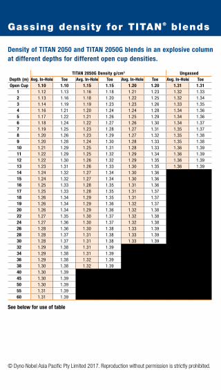
Gassing density for TITAN® blends
Density of TITAN 2050 and TITAN 2050G blends in an explosive column at different depths for different open cup densities.
Depth (m)TITAN 2050G Density g/cm3 Ungassed
Avg. In-Hole Toe Avg. In-Hole Toe Avg. In-Hole Toe Avg. In-Hole ToeOpen Cup 1.10 1.10 1.15 1.15 1.20 1.20 1.31 1.31
1 1.12 1.13 1.16 1.18 1.21 1.23 1.32 1.332 1.13 1.16 1.18 1.20 1.22 1.25 1.32 1.343 1.14 1.19 1.19 1.23 1.23 1.26 1.33 1.354 1.16 1.21 1.20 1.24 1.24 1.28 1.34 1.365 1.17 1.22 1.21 1.26 1.25 1.29 1.34 1.366 1.18 1.24 1.22 1.27 1.26 1.30 1.34 1.377 1.19 1.25 1.23 1.28 1.27 1.31 1.35 1.378 1.20 1.26 1.23 1.29 1.27 1.32 1.35 1.389 1.20 1.28 1.24 1.30 1.28 1.33 1.35 1.3810 1.21 1.29 1.25 1.31 1.28 1.33 1.36 1.3911 1.22 1.29 1.25 1.32 1.29 1.34 1.36 1.3912 1.22 1.30 1.26 1.32 1.29 1.35 1.36 1.3913 1.23 1.31 1.26 1.33 1.30 1.35 1.36 1.3914 1.24 1.32 1.27 1.34 1.30 1.3615 1.24 1.32 1.27 1.34 1.30 1.3616 1.25 1.33 1.28 1.35 1.31 1.3617 1.25 1.33 1.28 1.35 1.31 1.3718 1.26 1.34 1.29 1.35 1.31 1.3719 1.26 1.34 1.29 1.36 1.32 1.3720 1.26 1.34 1.29 1.36 1.32 1.3822 1.27 1.35 1.30 1.37 1.32 1.3824 1.27 1.36 1.30 1.37 1.32 1.3826 1.28 1.36 1.30 1.38 1.33 1.3928 1.28 1.37 1.31 1.38 1.33 1.3930 1.28 1.37 1.31 1.38 1.33 1.3932 1.29 1.38 1.31 1.3934 1.29 1.38 1.31 1.3936 1.29 1.38 1.32 1.3938 1.30 1.38 1.32 1.3940 1.30 1.3945 1.30 1.3950 1.30 1.3955 1.31 1.3960 1.31 1.39
See below for use of table

© Dyno Nobel Asia Pacific Pty Limited 2017. Reproduction without permission is strictly prohibited.
USE OF TABLE
1. The left hand column in this table (Depth) indicates the height of the product column under dry or dewatered hole conditions.
2. This table applies for TITAN 2000 Matrix blends with an emulsion content of 50% w/w ONLY, i.e. T2050G and T2050.
3. Emulsion explosives behave as liquids when subjected to the gravitational stress in a vertical blasthole, and a pressure gradient in the explosive will be established. The higher the explosive column in the blasthole, the higher the internal pressure at the bottom of the column, and the larger the quantity of gassing chemicals that need to be added to provide sensitisation.
4. The open cup density is a measure of the level of sensitisation of the product. It is necessary to choose an open cup density to ensure that the density of the explosive at the bottom of the blasthole is less than the critical density. Inappropriate sensitisation may lead to poor detonation, fragmentation and generation of excessive post blast fume. Blacked out areas indicate where critical density is reached or exceeded.
5. To determine the required open cup density for an explosive column of 40m (for example), find 40m in the Depth column. Moving to the right, read off the density in the unshaded column under the required open cup density (a Toe density of 1.39g/cm3 in the 1.10g/cm3 open cup density column). This indicates that sufficient gassing chemicals should be added to the gassed explosive blend during delivery so that an open cup density of 1.10g/cm3 is achieved. This level of gassing chemicals will ensure that the density at the bottom of the column will be below the critical density, and the column will detonate at full order upon initiation.
6. To determine the approximate average in-hole density in a column of 40m (for example), find 40m in the Depth column. Moving to the right, read off the density in the shaded column (an Avg. In-Hole density of 1.30g/cm3 in the 1.10 g/cm3 open cup density column).
For depths that are not listed, Dyno Nobel recommends rounding up to the next highest depth e.g. a 25m deep hole should be rounded to 26m and corresponding densities applied.
7. Blast design should be based on average in-hole density whilst blasthole loading requires the MPU operator to achieve the associated open cup density.
8. The gassing reaction takes 30-40 minutes to achieve the desired open cup density at 20°C. It is necessary to allow at least this time to elapse following completion of loading and before stemming the charged blasthole. A longer period should be allowed at lower temperatures.
9. The density values shown were calculated using a laboratory mathematical model that was validated using a specially designed fit-for-purpose pressure-volume apparatus.
10. The low density explosive grade ammonium nitrate used in the model was assigned a bulk density of 0.77 g/cm3 and a particle density of 1.58 g/cm3.

© Dyno Nobel Asia Pacific Pty Limited 2017. Reproduction without permission is strictly prohibited.
Density of TITAN 2060G blends in an explosive column at different depths for different open cup densities.
Depth (m)
TITAN 2060G Density g/cm3
Avg. In-Hole Toe
Avg. In-Hole Toe
Avg. In-Hole Toe
Avg. In-Hole Toe
Avg. In-Hole Toe
Avg. In-Hole Toe
Avg. In-Hole Toe
Open Cup 0.90 0.90 0.95 0.95 1.00 1.00 1.05 1.05 1.10 1.10 1.15 1.15 1.20 1.201 0.92 0.94 0.97 0.99 1.02 1.04 1.07 1.08 1.12 1.13 1.16 1.18 1.21 1.222 0.94 0.98 0.99 1.02 1.04 1.07 1.08 1.11 1.13 1.16 1.18 1.20 1.22 1.243 0.96 1.01 1.00 1.06 1.05 1.10 1.10 1.14 1.14 1.18 1.19 1.22 1.23 1.264 0.97 1.04 1.02 1.08 1.07 1.12 1.11 1.16 1.15 1.20 1.20 1.24 1.24 1.275 0.99 1.07 1.03 1.11 1.08 1.14 1.12 1.18 1.16 1.22 1.21 1.25 1.25 1.286 1.00 1.09 1.05 1.13 1.09 1.16 1.13 1.20 1.17 1.23 1.21 1.26 1.25 1.297 1.02 1.11 1.06 1.15 1.10 1.18 1.14 1.21 1.18 1.24 1.22 1.27 1.26 1.308 1.03 1.13 1.07 1.16 1.11 1.19 1.15 1.22 1.19 1.25 1.23 1.28 1.26 1.319 1.04 1.15 1.08 1.18 1.12 1.21 1.16 1.24 1.20 1.26 1.23 1.29 1.27 1.3210 1.05 1.16 1.09 1.19 1.13 1.22 1.17 1.25 1.20 1.27 1.24 1.30 1.27 1.3211 1.06 1.18 1.10 1.20 1.14 1.23 1.17 1.26 1.21 1.28 1.25 1.30 1.28 1.3312 1.07 1.19 1.11 1.21 1.15 1.24 1.18 1.26 1.22 1.29 1.25 1.31 1.28 1.3313 1.08 1.20 1.12 1.22 1.15 1.25 1.19 1.27 1.22 1.29 1.25 1.32 1.29 1.3414 1.09 1.21 1.13 1.23 1.16 1.26 1.19 1.28 1.23 1.30 1.26 1.32 1.29 1.3415 1.10 1.22 1.13 1.24 1.17 1.26 1.20 1.29 1.23 1.31 1.26 1.33 1.29 1.3416 1.11 1.23 1.14 1.25 1.17 1.27 1.21 1.29 1.24 1.31 1.27 1.33 1.30 1.3517 1.11 1.24 1.15 1.26 1.18 1.28 1.21 1.30 1.24 1.32 1.27 1.33 1.30 1.3518 1.12 1.24 1.15 1.26 1.18 1.28 1.22 1.30 1.25 1.32 1.27 1.34 1.30 1.3519 1.13 1.25 1.16 1.27 1.19 1.29 1.22 1.31 1.25 1.32 1.28 1.34 1.31 1.3620 1.13 1.26 1.16 1.28 1.19 1.29 1.22 1.31 1.25 1.33 1.28 1.34 1.31 1.3622 1.14 1.27 1.17 1.29 1.20 1.30 1.23 1.32 1.26 1.33 1.28 1.35 1.31 1.3624 1.15 1.28 1.18 1.30 1.20 1.31 1.23 1.33 1.26 1.34 1.29 1.35 1.31 1.3726 1.15 1.29 1.18 1.30 1.21 1.32 1.24 1.33 1.26 1.34 1.29 1.36 1.32 1.3728 1.16 1.30 1.19 1.31 1.21 1.32 1.24 1.34 1.27 1.35 1.29 1.36 1.32 1.3730 1.16 1.30 1.19 1.32 1.22 1.33 1.24 1.34 1.27 1.35 1.30 1.3632 1.17 1.31 1.20 1.32 1.22 1.33 1.25 1.35 1.27 1.36 1.30 1.3734 1.17 1.32 1.20 1.33 1.23 1.34 1.25 1.35 1.28 1.36 1.30 1.3736 1.18 1.32 1.20 1.33 1.23 1.34 1.26 1.35 1.28 1.36 1.30 1.3738 1.18 1.33 1.21 1.34 1.23 1.35 1.26 1.36 1.28 1.37 1.31 1.3740 1.19 1.33 1.21 1.34 1.24 1.35 1.26 1.36 1.29 1.3745 1.19 1.33 1.22 1.34 1.24 1.35 1.27 1.36 1.29 1.3750 1.20 1.33 1.22 1.34 1.25 1.35 1.27 1.36 1.29 1.3755 1.20 1.34 1.23 1.35 1.25 1.35 1.27 1.36 1.29 1.3760 1.21 1.34 1.23 1.35 1.25 1.36 1.27 1.36 1.29 1.37
See below for use of table
Gassing density for TITAN® blends

© Dyno Nobel Asia Pacific Pty Limited 2017. Reproduction without permission is strictly prohibited.
USE OF TABLE
1. The left hand column in this table (Depth) indicates the height of the product column under dry hole conditions. In wet hole conditions, the value selected from the left hand column must be the sum of the product column and the height of the water column in the hole. If the length of the product and water column exceeds the depth of the hole then the value selected from the left hand column must be the hole depth.
2. This table applies for TITAN 2000 Matrix blends with an emulsion content of 60% w/w ONLY, i.e. T2060G.
3. Emulsion explosives behave as liquids when subjected to the gravitational stress in a vertical blasthole, and a pressure gradient in the explosive will be established. The higher the explosive column in the blasthole, the higher the internal pressure at the bottom of the column, and the larger the quantity of gassing chemicals that need to be added to provide sensitisation.
4. The open cup density is a measure of the level of sensitisation of the product. It is necessary to choose an open cup density to ensure that the density of the explosive at the bottom of the blasthole is less than the critical density. Inappropriate sensitisation may lead to poor detonation, fragmentation and generation of excessive post blast fume. Blacked out areas indicate where critical density is reached or exceeded.
5. To determine the required open cup density for an explosive column of 40m (for example), find 40m in the Depth column. Moving to the right, read off the density in the unshaded column under the required open cup density (a Toe density of 1.37g/cm3 in the 1.10 g/cm3 open cup density column). This indicates that sufficient gassing chemicals should be added to the gassed explosive blend during delivery so that an open cup density of 1.10g/cm3 is achieved. This level of gassing chemicals will ensure that the density at the bottom of the column will be below the critical density, and the column will detonate at full order upon initiation.
6. To determine the approximate average in-hole density in a column of 40m (for example), find 40m in the Depth column. Moving to the right, read off the density in the shaded column (an Avg. In-Hole density of 1.29g/cm3 in the 1.10 g/cm3 open cup density column). For depths that are not listed, Dyno Nobel recommends rounding up to the next highest depth. e.g. a 25m deep hole should be rounded to 26m and corresponding densities applied.
7. Blast design should be based on average in-hole density whilst blasthole loading requires the MPU operator to achieve the associated open cup density.
8. The gassing reaction takes 30-40 minutes to achieve the desired open cup density at 20°C. It is necessary to allow at least this time to elapse following completion of loading and before stemming the charged blasthole. A longer period should be allowed at lower temperatures.
9. The density values shown were calculated using a laboratory mathematical model that was validated using a specially designed fit-for-purpose pressure-volume apparatus.
10. The low density explosive grade ammonium nitrate used in the model was assigned a bulk density of 0.77 g/cm3 and a particle density of 1.58 g/cm3.

© Dyno Nobel Asia Pacific Pty Limited 2017. Reproduction without permission is strictly prohibited.
Density of TITAN 2070G blends in an explosive column at different depths for different open cup densities.
Depth (m)
TITAN 2070G Density g/cm3
Avg. In-Hole Toe
Avg. In-Hole Toe
Avg. In-Hole Toe
Avg. In-Hole Toe
Avg. In-Hole Toe
Avg. In-Hole Toe
Avg. In-Hole Toe
Open Cup 0.90 0.90 0.95 0.95 1.00 1.00 1.05 1.05 1.10 1.10 1.15 1.15 1.20 1.201 0.92 0.94 0.97 0.99 1.02 1.04 1.07 1.08 1.11 1.13 1.16 1.17 1.21 1.222 0.94 0.98 0.99 1.02 1.03 1.07 1.08 1.11 1.13 1.15 1.17 1.20 1.22 1.243 0.96 1.01 1.00 1.05 1.05 1.09 1.09 1.13 1.14 1.17 1.18 1.21 1.23 1.254 0.97 1.03 1.02 1.08 1.06 1.12 1.11 1.15 1.15 1.19 1.19 1.23 1.23 1.265 0.99 1.06 1.03 1.10 1.07 1.14 1.12 1.17 1.16 1.21 1.20 1.24 1.24 1.276 1.00 1.08 1.04 1.12 1.09 1.15 1.13 1.19 1.17 1.22 1.21 1.25 1.25 1.287 1.01 1.10 1.05 1.14 1.10 1.17 1.14 1.20 1.18 1.23 1.21 1.26 1.25 1.298 1.02 1.12 1.07 1.15 1.11 1.18 1.14 1.21 1.18 1.24 1.22 1.27 1.26 1.309 1.04 1.14 1.08 1.17 1.11 1.20 1.15 1.22 1.19 1.25 1.23 1.28 1.26 1.3010 1.05 1.15 1.08 1.18 1.12 1.21 1.16 1.23 1.20 1.26 1.23 1.28 1.27 1.3111 1.06 1.16 1.09 1.19 1.13 1.22 1.17 1.24 1.20 1.27 1.24 1.29 1.27 1.3112 1.06 1.17 1.10 1.20 1.14 1.23 1.17 1.25 1.21 1.27 1.24 1.30 1.27 1.3213 1.07 1.19 1.11 1.21 1.15 1.23 1.18 1.26 1.21 1.28 1.25 1.30 1.28 1.3214 1.08 1.20 1.12 1.22 1.15 1.24 1.19 1.26 1.22 1.29 1.25 1.31 1.28 1.3315 1.09 1.20 1.12 1.23 1.16 1.25 1.19 1.27 1.22 1.29 1.25 1.31 1.28 1.3316 1.10 1.21 1.13 1.24 1.16 1.26 1.20 1.28 1.23 1.30 1.26 1.31 1.29 1.3317 1.10 1.22 1.14 1.24 1.17 1.26 1.20 1.28 1.23 1.30 1.26 1.32 1.29 1.3318 1.11 1.23 1.14 1.25 1.17 1.27 1.20 1.29 1.23 1.30 1.26 1.32 1.29 1.3419 1.12 1.23 1.15 1.25 1.18 1.27 1.21 1.29 1.24 1.31 1.27 1.32 1.29 1.3420 1.12 1.24 1.15 1.26 1.18 1.28 1.21 1.29 1.24 1.31 1.27 1.33 1.30 1.3422 1.13 1.25 1.16 1.27 1.19 1.29 1.22 1.30 1.25 1.32 1.27 1.33 1.30 1.3524 1.13 1.26 1.16 1.28 1.19 1.29 1.22 1.31 1.25 1.32 1.28 1.34 1.30 1.3526 1.14 1.27 1.17 1.29 1.20 1.30 1.22 1.31 1.25 1.33 1.28 1.34 1.30 1.3528 1.15 1.28 1.17 1.29 1.20 1.31 1.23 1.32 1.25 1.33 1.28 1.34 1.31 1.3530 1.15 1.28 1.18 1.30 1.21 1.31 1.23 1.32 1.26 1.33 1.28 1.3532 1.16 1.29 1.18 1.30 1.21 1.32 1.24 1.33 1.26 1.34 1.29 1.3534 1.16 1.30 1.19 1.31 1.21 1.32 1.24 1.33 1.26 1.34 1.29 1.3536 1.17 1.30 1.19 1.31 1.22 1.32 1.24 1.33 1.27 1.34 1.29 1.3538 1.17 1.31 1.20 1.32 1.22 1.33 1.25 1.34 1.27 1.3540 1.17 1.31 1.20 1.32 1.22 1.33 1.25 1.34 1.27 1.3545 1.18 1.31 1.20 1.32 1.23 1.33 1.25 1.34 1.27 1.3550 1.18 1.31 1.21 1.32 1.23 1.33 1.25 1.34 1.28 1.3555 1.19 1.32 1.21 1.33 1.23 1.33 1.26 1.34 1.28 1.3560 1.19 1.32 1.21 1.33 1.24 1.34 1.26 1.34 1.28 1.35
See below for use of table
Gassing density for TITAN® blends

© Dyno Nobel Asia Pacific Pty Limited 2017. Reproduction without permission is strictly prohibited.
USE OF TABLE
1. The left hand column in this table (Depth) indicates the height of the product column under dry hole conditions. In wet hole conditions, the value selected from the left hand column must be the sum of the product column plus the height of the water column in the hole. If the length of the product and water column exceeds the depth of the hole then the value selected from the left hand column must be the hole depth.
2. This table applies for TITAN 2000 Matrix blends with an emulsion content of 70% w/w ONLY, i.e. T2070G.
3. Emulsion explosives behave as liquids when subjected to the gravitational stress in a vertical blasthole, and a pressure gradient in the explosive will be established. The higher the explosive column in the blasthole, the higher the internal pressure at the bottom of the column, and the larger the quantity of gassing chemicals that need to be added to provide sensitisation.
4. The open cup density is a measure of the level of sensitisation of the product. It is necessary to choose an open cup density to ensure that the density of the explosive at the bottom of the blasthole is less than the critical density. Inappropriate sensitisation may lead to poor detonation, fragmentation and generation of excessive post blast fume. Blacked out areas indicate where critical density is reached or exceeded.
5. To determine the required open cup density for an explosive column of 40m (for example), find 40m in the Depth column. Moving to the right, read off the density in the unshaded column under the required open cup density (a Toe density of 1.35g/cm3 in the 1.10 g/cm3 open cup density column). This indicates that sufficient gassing chemicals should be added to the gassed explosive blend during delivery so that an open cup density of 1.10g/cm3 is achieved. This level of gassing chemicals will ensure that the density at the bottom of the column will be below the critical density, and the column will detonate at full order upon initiation.
6. To determine the approximate average in-hole density in a column of 40m (for example), find 40m in the Depth column. Moving to the right, read off the density in the shaded column (an Avg. In-Hole density of 1.27g/cm3 in the 1.10 g/cm3 open cup density column). For depths that are not listed, Dyno Nobel recommends rounding up to the next highest depth. e.g. a 25m deep hole should be rounded to 26m and corresponding densities applied.
7. Blast design should be based on average in-hole density whilst blasthole loading requires the MPU operator to achieve the associated open cup density.
8. The gassing reaction takes 30-40 minutes to achieve the desired open cup density at 20°C. It is necessary to allow at least this time to elapse following completion of loading and before stemming the charged blasthole. A longer period should be allowed at lower temperatures.
9. The density values shown were calculated using a laboratory mathematical model that was validated using a specially designed fit-for-purpose pressure-volume apparatus.
10. The low density explosive grade ammonium nitrate used in the model was assigned a bulk density of 0.77 g/cm3 and a particle density of 1.58 g/cm3.

© Dyno Nobel Asia Pacific Pty Limited 2017. Reproduction without permission is strictly prohibited.
Density of gas sensitised and ungassed blends containing 50% TITAN 3000, TITAN 5000 or TITAN 9000 in an explosive column at different depths for different open cup densities.
Depth (m)
Gassed blend containing 50% emulsion – Density g/cm3 UngassedAvg.
In-Hole ToeAvg.
In-Hole ToeAvg.
In-Hole ToeAvg.
In-Hole ToeOpen Cup 1.10 1.10 1.15 1.15 1.20 1.20 1.32 1.32
1 1.12 1.13 1.17 1.18 1.21 1.23 1.33 1.342 1.13 1.16 1.18 1.21 1.23 1.25 1.33 1.353 1.15 1.19 1.19 1.23 1.24 1.27 1.34 1.364 1.16 1.21 1.20 1.25 1.25 1.28 1.35 1.375 1.17 1.23 1.21 1.26 1.25 1.30 1.35 1.376 1.18 1.25 1.22 1.28 1.26 1.31 1.36 1.387 1.19 1.26 1.23 1.29 1.27 1.32 1.36 1.398 1.20 1.27 1.24 1.30 1.28 1.33 1.36 1.399 1.21 1.28 1.25 1.31 1.28 1.34 1.37 1.4010 1.22 1.29 1.25 1.32 1.29 1.34 1.37 1.4011 1.22 1.30 1.26 1.33 1.29 1.35 1.37 1.4012 1.23 1.31 1.26 1.33 1.30 1.3613 1.24 1.32 1.27 1.34 1.30 1.3614 1.24 1.32 1.27 1.35 1.31 1.3715 1.25 1.33 1.28 1.35 1.31 1.3716 1.25 1.34 1.28 1.36 1.31 1.3717 1.26 1.34 1.29 1.36 1.32 1.3818 1.26 1.35 1.29 1.36 1.32 1.3819 1.27 1.35 1.30 1.37 1.32 1.3820 1.27 1.36 1.30 1.37 1.33 1.3922 1.28 1.36 1.30 1.38 1.33 1.3924 1.28 1.37 1.31 1.38 1.33 1.4026 1.28 1.37 1.31 1.39 1.34 1.4028 1.29 1.38 1.31 1.39 1.34 1.4030 1.29 1.38 1.32 1.4032 1.29 1.39 1.32 1.4034 1.30 1.39 1.32 1.4036 1.30 1.39 1.33 1.4038 1.30 1.4040 1.31 1.4045 1.31 1.4050 1.31 1.4055 1.32 1.4060 1.32 1.40
See below for use of table
Gassing density for TITAN® blends

© Dyno Nobel Asia Pacific Pty Limited 2017. Reproduction without permission is strictly prohibited.
USE OF TABLE
1. The left hand column in this table (Depth) indicates the height of the product column under dry or dewatered hole conditions.
2. This table applies for TITAN 3000, TITAN 5000 and TITAN 9000 Matrix blends with an emulsion content of 50% w/w ONLY, i.e. T9050/T9050G.
3. Emulsion explosives behave as liquids when subjected to the gravitational stress in vertical and near vertical blastholes and a pressure gradient in the explosive will be established. The higher the explosive column in the blasthole, the higher the internal pressure at the bottom of the column, and the larger the quantity of gassing chemicals that need to be added to provide sensitisation.
4. The open cup density is a measure of the level of sensitisation of the product. It is necessary to choose an open cup density to ensure that the density of the explosive at the bottom of the blasthole is less than the critical density. Inappropriate sensitisation may lead to poor detonation, fragmentation and generation of excessive post blast fume. Blacked out areas indicate where critical density is reached or exceeded.
5. To determine the required open cup density for an explosive column of 40m (for example), find 40m in the Depth column. Moving to the right, read off the density in the unshaded column under the required open cup density (a Toe density of 1.40g/cm3 in the 1.10 g/cm3 open cup density column). This indicates that sufficient gassing chemicals should be added to the gassed explosive blend during delivery so that an open cup density of 1.10g/cm3 is achieved. This level of gassing chemicals will ensure that the density at the bottom of the column will be below the critical density, and the column will detonate at full order upon initiation.
6. To determine the approximate average in-hole density in a column of 40m (for example), find 40m in the Depth column. Moving to the right, read off the density in the shaded column (an Avg. In-Hole density of 1.31g/cm3 in the 1.10 g/cm3 open cup density column). For depths that are not listed, Dyno Nobel recommends rounding up to the next highest depth. e.g. a 25m deep hole should be rounded to 26m and corresponding densities applied.
7. Blast design should be based on average in-hole density whilst blasthole loading requires the MPU operator to achieve the associated open cup density.
8. The gassing reaction takes 30-40 minutes to achieve the desired open cup density at 20°C. It is necessary to allow at least this time to elapse following completion of loading and before stemming the charged blasthole. A longer period should be allowed at lower temperatures.
9. The density values shown were calculated using a laboratory mathematical model that was validated using a specially designed fit-for-purpose pressure-volume apparatus.
10. The low density explosive grade ammonium nitrate used in the model was assigned a bulk density of 0.77 g/cm3 and a particle density of 1.58 g/cm3.

© Dyno Nobel Asia Pacific Pty Limited 2017. Reproduction without permission is strictly prohibited.
Density of gas sensitised blends containing 60% TITAN 3000, TITAN 5000 or TITAN 9000 in an explosive column at different depths for different open cup densities.
Depth (m)
Gassed blend containing 60% emulsion – Density g/cm3
Avg. In-Hole Toe
Avg. In-Hole Toe
Avg. In-Hole Toe
Avg. In-Hole Toe
Avg. In-Hole Toe
Avg. In-Hole Toe
Avg. In-Hole Toe
Open Cup 0.90 0.90 0.95 0.95 1.00 1.00 1.05 1.05 1.10 1.10 1.15 1.15 1.20 1.201 0.92 0.94 0.97 0.99 1.02 1.04 1.07 1.09 1.12 1.13 1.16 1.18 1.21 1.222 0.94 0.98 0.99 1.03 1.04 1.07 1.08 1.12 1.13 1.16 1.18 1.20 1.22 1.253 0.96 1.02 1.01 1.06 1.05 1.10 1.10 1.14 1.14 1.18 1.19 1.22 1.23 1.264 0.98 1.05 1.02 1.09 1.07 1.13 1.11 1.17 1.16 1.20 1.20 1.24 1.24 1.285 0.99 1.07 1.04 1.11 1.08 1.15 1.12 1.19 1.17 1.22 1.21 1.26 1.25 1.296 1.01 1.10 1.05 1.13 1.09 1.17 1.14 1.20 1.18 1.24 1.22 1.27 1.26 1.307 1.02 1.12 1.06 1.15 1.11 1.19 1.15 1.22 1.19 1.25 1.23 1.28 1.26 1.318 1.04 1.14 1.08 1.17 1.12 1.20 1.16 1.23 1.19 1.26 1.23 1.29 1.27 1.329 1.05 1.16 1.09 1.19 1.13 1.22 1.17 1.25 1.20 1.27 1.24 1.30 1.28 1.33
10 1.06 1.17 1.10 1.20 1.14 1.23 1.17 1.26 1.21 1.28 1.25 1.31 1.28 1.3311 1.07 1.19 1.11 1.21 1.14 1.24 1.18 1.27 1.22 1.29 1.25 1.32 1.29 1.3412 1.08 1.20 1.12 1.23 1.15 1.25 1.19 1.28 1.22 1.30 1.26 1.32 1.29 1.3413 1.09 1.21 1.13 1.24 1.16 1.26 1.20 1.28 1.23 1.31 1.26 1.33 1.29 1.3514 1.10 1.22 1.13 1.25 1.17 1.27 1.20 1.29 1.23 1.31 1.27 1.33 1.30 1.3515 1.11 1.23 1.14 1.25 1.17 1.28 1.21 1.30 1.24 1.32 1.27 1.34 1.30 1.3616 1.11 1.24 1.15 1.26 1.18 1.28 1.21 1.30 1.24 1.32 1.28 1.34 1.31 1.3617 1.12 1.25 1.15 1.27 1.19 1.29 1.22 1.31 1.25 1.33 1.28 1.35 1.31 1.3618 1.13 1.26 1.16 1.28 1.19 1.30 1.22 1.31 1.25 1.33 1.28 1.35 1.31 1.3719 1.14 1.26 1.17 1.28 1.20 1.30 1.23 1.32 1.26 1.34 1.29 1.35 1.31 1.3720 1.14 1.27 1.17 1.29 1.20 1.31 1.23 1.32 1.26 1.34 1.29 1.36 1.32 1.3722 1.15 1.28 1.18 1.30 1.21 1.32 1.24 1.33 1.27 1.35 1.29 1.36 1.32 1.3824 1.15 1.29 1.18 1.31 1.21 1.32 1.24 1.34 1.27 1.35 1.30 1.37 1.32 1.3826 1.16 1.30 1.19 1.32 1.22 1.33 1.25 1.35 1.27 1.36 1.30 1.37 1.32 1.3828 1.17 1.31 1.20 1.32 1.22 1.34 1.25 1.35 1.28 1.36 1.30 1.38 1.33 1.3930 1.17 1.32 1.20 1.33 1.23 1.34 1.25 1.36 1.28 1.37 1.31 1.38 1.33 1.3932 1.18 1.32 1.21 1.34 1.23 1.35 1.26 1.36 1.28 1.37 1.31 1.38 1.33 1.3934 1.18 1.33 1.21 1.34 1.24 1.35 1.26 1.36 1.29 1.37 1.31 1.3936 1.19 1.34 1.22 1.35 1.24 1.36 1.27 1.37 1.29 1.38 1.31 1.3938 1.19 1.34 1.22 1.35 1.24 1.36 1.27 1.37 1.29 1.38 1.32 1.3940 1.20 1.35 1.22 1.36 1.25 1.36 1.27 1.37 1.30 1.38 1.32 1.3945 1.20 1.35 1.23 1.36 1.25 1.37 1.28 1.38 1.30 1.38 1.32 1.3950 1.21 1.35 1.23 1.36 1.26 1.37 1.28 1.38 1.30 1.39 1.32 1.3955 1.21 1.35 1.24 1.36 1.26 1.37 1.28 1.38 1.30 1.39 1.33 1.3960 1.22 1.35 1.24 1.36 1.26 1.37 1.28 1.38 1.31 1.39 1.33 1.39
See below for use of table
Gassing density for TITAN® blends

© Dyno Nobel Asia Pacific Pty Limited 2017. Reproduction without permission is strictly prohibited.
USE OF TABLE
1. The left hand column in this table (Depth) indicates the height of the product column under dry hole conditions. In wet hole conditions, the value selected from the left hand column must be the sum of the product column and the height of the water column in the hole. If the length of the product and water column exceeds the depth of the hole then the value selected from the left hand column must be the hole depth.
2. This table applies for TITAN 3000, TITAN 5000 and TITAN 9000 Matrix blends with an emulsion content of 60% w/w ONLY, i.e. T9060G.
3. Emulsion explosives behave as liquids when subjected to the gravitational stress in vertical and near vertical blastholes and a pressure gradient in the explosive will be established. The higher the explosive column in the blasthole, the higher the internal pressure at the bottom of the column, and the larger the quantity of gassing chemicals that need to be added to provide sensitisation.
4. The open cup density is a measure of the level of sensitisation of the product. It is necessary to choose an open cup density to ensure that the density of the explosive at the bottom of the blasthole is less than the critical density. Inappropriate sensitisation may lead to poor detonation, fragmentation and generation of excessive post blast fume. Blacked out areas indicate where critical density is reached or exceeded.
5. To determine the required open cup density for an explosive column of 40m (for example), find 40m in the Depth column. Moving to the right, read off the density in the unshaded column under the required open cup density (a Toe density of 1.38g/cm3 in the 1.10 g/cm3 open cup density column). This indicates that sufficient gassing chemicals should be added to the gassed explosive blend during delivery so that an open cup density of 1.10g/cm3 is achieved. This level of gassing chemicals will ensure that the density at the bottom of the column will be below the critical density, and the column will detonate at full order upon initiation.
6. To determine the approximate average in-hole density in a column of 40m (for example), find 40m in the Depth column. Moving to the right, read off the density in the shaded column (an Avg. In-Hole density of 1.30g/cm3 in the 1.10 g/cm3 open cup density column). For depths that are not listed, Dyno Nobel recommends rounding up to the next highest depth. e.g. a 25m deep hole should be rounded to 26m and corresponding densities applied.
7. Blast design should be based on average in-hole density whilst blasthole loading requires the MPU operator to achieve the associated open cup density.
8. The gassing reaction takes 30-40 minutes to achieve the desired open cup density at 20°C. It is necessary to allow at least this time to elapse following completion of loading and before stemming the charged blasthole. A longer period should be allowed at lower temperatures.
9. The density values shown were calculated using a laboratory mathematical model that was validated using a specially designed fit-for-purpose pressure-volume apparatus.
10. The low density explosive grade ammonium nitrate used in the model was assigned a bulk density of 0.77 g/cm3 and a particle density of 1.58 g/cm3.

© Dyno Nobel Asia Pacific Pty Limited 2017. Reproduction without permission is strictly prohibited.
Density of gas sensitised blends containing 70% TITAN 3000, TITAN 5000 or TITAN 9000 in an explosive column at different depths for different open cup densities.
Depth (m)
Gassed blend containing 70% emulsion – Density g/cm3
Avg. In-Hole Toe
Avg. In-Hole Toe
Avg. In-Hole Toe
Avg. In-Hole Toe
Avg. In-Hole Toe
Avg. In-Hole Toe
Avg. In-Hole Toe
Open Cup 0.90 0.90 0.95 0.95 1.00 1.00 1.05 1.05 1.10 1.10 1.15 1.15 1.20 1.201 0.92 0.94 0.97 0.99 1.02 1.04 1.07 1.08 1.12 1.13 1.16 1.18 1.21 1.222 0.94 0.98 0.99 1.02 1.04 1.07 1.08 1.11 1.13 1.16 1.18 1.20 1.22 1.243 0.96 1.01 1.00 1.05 1.05 1.10 1.10 1.14 1.14 1.18 1.19 1.22 1.23 1.264 0.97 1.04 1.02 1.08 1.07 1.12 1.11 1.16 1.15 1.20 1.20 1.23 1.24 1.275 0.99 1.07 1.03 1.11 1.08 1.14 1.12 1.18 1.16 1.21 1.20 1.25 1.25 1.286 1.00 1.09 1.05 1.13 1.09 1.16 1.13 1.20 1.17 1.23 1.21 1.26 1.25 1.297 1.02 1.11 1.06 1.15 1.10 1.18 1.14 1.21 1.18 1.24 1.22 1.27 1.26 1.308 1.03 1.13 1.07 1.16 1.11 1.19 1.15 1.22 1.19 1.25 1.23 1.28 1.26 1.319 1.04 1.15 1.08 1.18 1.12 1.21 1.16 1.24 1.20 1.26 1.23 1.29 1.27 1.3210 1.05 1.16 1.09 1.19 1.13 1.22 1.17 1.25 1.20 1.27 1.24 1.30 1.27 1.3211 1.06 1.17 1.10 1.20 1.14 1.23 1.17 1.25 1.21 1.28 1.24 1.30 1.28 1.3312 1.07 1.19 1.11 1.21 1.15 1.24 1.18 1.26 1.22 1.29 1.25 1.31 1.28 1.3313 1.08 1.20 1.12 1.22 1.15 1.25 1.19 1.27 1.22 1.29 1.25 1.31 1.29 1.3414 1.09 1.21 1.13 1.23 1.16 1.26 1.19 1.28 1.23 1.30 1.26 1.32 1.29 1.3415 1.10 1.22 1.13 1.24 1.17 1.26 1.20 1.28 1.23 1.30 1.26 1.32 1.29 1.3416 1.11 1.23 1.14 1.25 1.17 1.27 1.20 1.29 1.24 1.31 1.27 1.33 1.30 1.3517 1.11 1.24 1.15 1.26 1.18 1.28 1.21 1.30 1.24 1.31 1.27 1.33 1.30 1.3518 1.12 1.24 1.15 1.26 1.18 1.28 1.21 1.30 1.24 1.32 1.27 1.34 1.30 1.3519 1.13 1.25 1.16 1.27 1.19 1.29 1.22 1.31 1.25 1.32 1.28 1.34 1.30 1.3520 1.13 1.26 1.16 1.27 1.19 1.29 1.22 1.31 1.25 1.33 1.28 1.34 1.31 1.3622 1.14 1.27 1.17 1.29 1.20 1.30 1.23 1.32 1.26 1.33 1.28 1.35 1.31 1.3624 1.14 1.28 1.17 1.29 1.20 1.31 1.23 1.32 1.26 1.34 1.29 1.35 1.31 1.3726 1.15 1.29 1.18 1.30 1.21 1.32 1.24 1.33 1.26 1.34 1.29 1.36 1.31 1.3728 1.16 1.29 1.18 1.31 1.21 1.32 1.24 1.34 1.27 1.35 1.29 1.36 1.32 1.3730 1.16 1.30 1.19 1.32 1.22 1.33 1.24 1.34 1.27 1.35 1.29 1.36 1.32 1.3732 1.17 1.31 1.19 1.32 1.22 1.33 1.25 1.34 1.27 1.36 1.30 1.3734 1.17 1.31 1.20 1.33 1.23 1.34 1.25 1.35 1.28 1.36 1.30 1.3736 1.18 1.32 1.20 1.33 1.23 1.34 1.25 1.35 1.28 1.36 1.30 1.3738 1.18 1.32 1.21 1.33 1.23 1.34 1.26 1.35 1.28 1.36 1.30 1.3740 1.19 1.33 1.21 1.34 1.24 1.35 1.26 1.36 1.28 1.3745 1.19 1.33 1.22 1.34 1.24 1.35 1.26 1.36 1.29 1.3750 1.20 1.33 1.22 1.34 1.24 1.35 1.27 1.36 1.29 1.3755 1.20 1.34 1.22 1.34 1.25 1.35 1.27 1.36 1.29 1.3760 1.20 1.34 1.23 1.35 1.25 1.35 1.27 1.36 1.29 1.37
See below for use of table
Gassing density for TITAN® blends

© Dyno Nobel Asia Pacific Pty Limited 2017. Reproduction without permission is strictly prohibited.
USE OF TABLE
1. The left hand column in this table (Depth) indicates the height of the product column under dry hole conditions. In wet hole conditions, the value selected from the left hand column must be the sum of the product column and the height of the water column in the hole. If the length of the product and water column exceeds the depth of the hole then the value selected from the left hand column must be the hole depth.
2. This table applies for TITAN 3000, TITAN 5000 and TITAN 9000 Matrix blends with an emulsion content of 70% w/w ONLY, i.e. T9070G.
3. Emulsion explosives behave as liquids when subjected to the gravitational stress in vertical and near vertical blastholes and a pressure gradient in the explosive will be established. The higher the explosive column in the blasthole, the higher the internal pressure at the bottom of the column, and the larger the quantity of gassing chemicals that need to be added to provide sensitisation.
4. The open cup density is a measure of the level of sensitisation of the product. It is necessary to choose an open cup density to ensure that the density of the explosive at the bottom of the blasthole is less than the critical density. Inappropriate sensitisation may lead to poor detonation, fragmentation and generation of excessive post blast fume. Blacked out areas indicate where critical density is reached or exceeded.
5. To determine the required open cup density for an explosive column of 40m (for example), find 40m in the Depth column. Moving to the right, read off the density in the unshaded column under the required open cup density (a Toe density of 1.37g/cm3 in the 1.10 g/cm3 open cup density column). This indicates that sufficient gassing chemicals should be added to the gassed explosive blend during delivery so that an open cup density of 1.10g/cm3 is achieved. This level of gassing chemicals will ensure that the density at the bottom of the column will be below the critical density, and the column will detonate at full order upon initiation.
6. To determine the approximate average in-hole density in a column of 40m (for example), find 40m in the Depth column. Moving to the right, read off the density in the shaded column (an Avg. In-Hole density of 1.28g/cm3 in the 1.10 g/cm3 open cup density column). For depths that are not listed, Dyno Nobel recommends rounding up to the next highest depth. e.g. a 25m deep hole should be rounded to 26m and corresponding densities applied.
7. Blast design should be based on average in-hole density whilst blasthole loading requires the MPU operator to achieve the associated open cup density.
8. The gassing reaction takes 30-40 minutes to achieve the desired open cup density at 20°C. It is necessary to allow at least this time to elapse following completion of loading and before stemming the charged blasthole. A longer period should be allowed at lower temperatures.
9. The density values shown were calculated using a laboratory mathematical model that was validated using a specially designed fit-for-purpose pressure-volume apparatus.
10. The low density explosive grade ammonium nitrate used in the model was assigned a bulk density of 0.77 g/cm3 and a particle density of 1.58 g/cm3.
© Dyno Nobel Asia Pacific Pty Limited 2017. Reproduction without permission is strictly prohibited.
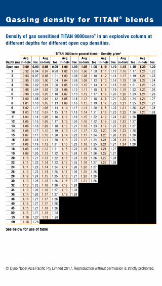
Density of gas sensitised TITAN 9000xero® in an explosive column at different depths for different open cup densities.
Depth (m)
TITAN 9000xero gassed blend – Density g/cm3
Avg in-hole Toe
Avg in-hole Toe
Avg in-hole Toe
Avg in-hole Toe
Avg in-hole Toe
Avg in-hole Toe
Avg in-hole Toe
Open cup 0.90 0.90 0.95 0.95 1.00 1.00 1.05 1.05 1.10 1.10 1.15 1.15 1.20 1.201 0.92 0.94 0.97 0.98 1.02 1.03 1.06 1.08 1.11 1.12 1.16 1.17 1.21 1.222 0.93 0.97 0.98 1.01 1.03 1.06 1.08 1.10 1.12 1.14 1.17 1.19 1.21 1.233 0.95 1.00 1.00 1.04 1.04 1.08 1.09 1.12 1.13 1.16 1.18 1.20 1.22 1.244 0.96 1.02 1.01 1.06 1.05 1.10 1.10 1.14 1.14 1.18 1.18 1.21 1.23 1.255 0.98 1.04 1.02 1.08 1.06 1.12 1.11 1.15 1.15 1.19 1.19 1.22 1.23 1.266 0.99 1.06 1.03 1.10 1.07 1.13 1.12 1.17 1.16 1.20 1.20 1.23 1.24 1.267 1.00 1.08 1.04 1.12 1.08 1.15 1.12 1.18 1.16 1.21 1.20 1.24 1.24 1.278 1.01 1.10 1.05 1.13 1.09 1.16 1.13 1.19 1.17 1.22 1.21 1.25 1.24 1.279 1.02 1.11 1.06 1.14 1.10 1.17 1.14 1.20 1.18 1.23 1.21 1.25 1.25 1.2810 1.03 1.12 1.07 1.15 1.11 1.18 1.14 1.21 1.18 1.23 1.22 1.26 1.25 1.2811 1.04 1.14 1.08 1.16 1.11 1.19 1.15 1.22 1.19 1.24 1.22 1.2612 1.05 1.15 1.09 1.17 1.12 1.20 1.16 1.22 1.19 1.25 1.22 1.2713 1.06 1.16 1.09 1.18 1.13 1.21 1.16 1.23 1.19 1.25 1.23 1.2714 1.06 1.17 1.10 1.19 1.13 1.21 1.17 1.23 1.20 1.26 1.23 1.2815 1.07 1.17 1.10 1.20 1.14 1.22 1.17 1.24 1.20 1.26 1.23 1.2816 1.08 1.18 1.11 1.20 1.14 1.22 1.17 1.24 1.21 1.26 1.24 1.2817 1.08 1.19 1.12 1.21 1.15 1.23 1.18 1.25 1.21 1.27 1.24 1.2818 1.09 1.19 1.12 1.21 1.15 1.23 1.18 1.25 1.21 1.2719 1.09 1.20 1.13 1.22 1.16 1.24 1.19 1.26 1.22 1.2720 1.10 1.21 1.13 1.22 1.16 1.24 1.19 1.26 1.22 1.2822 1.11 1.22 1.14 1.23 1.16 1.25 1.19 1.27 1.22 1.2824 1.11 1.23 1.14 1.24 1.17 1.26 1.20 1.2726 1.12 1.23 1.14 1.25 1.17 1.26 1.20 1.2828 1.12 1.24 1.15 1.25 1.18 1.27 1.20 1.2830 1.13 1.25 1.15 1.26 1.18 1.27 1.21 1.2832 1.13 1.25 1.16 1.26 1.18 1.2834 1.13 1.26 1.16 1.27 1.19 1.2836 1.14 1.26 1.17 1.27 1.19 1.2838 1.14 1.27 1.17 1.2840 1.15 1.27 1.17 1.2845 1.15 1.27 1.18 1.2850 1.15 1.27 1.18 1.2855 1.16 1.27 1.18 1.2860 1.16 1.28
See below for use of table
Gassing density for TITAN® blends

© Dyno Nobel Asia Pacific Pty Limited 2017. Reproduction without permission is strictly prohibited.
USE OF TABLE1. The left hand column in this table (Depth) indicates the height of the product column under dry hole
conditions. In wet hole conditions, the value selected from the left hand column must be the sum of the product column plus the height of the water column in the hole. If the length of the product and water column exceeds the depth of the hole then the value selected from the left hand column must be the hole depth.
2. This table applies for TITAN 9000xero Matrix blend with an emulsion content of 80% w/w ONLY. 3. Emulsion explosives behave as liquids when subjected to the gravitational stress in a vertical
blasthole, and a pressure gradient in the explosive will be established. The higher the explosive column in the blasthole, the higher the internal pressure at the bottom of the column, and the larger the quantity of gassing chemicals that need to be added to provide sensitisation.
4. The open cup density is a measure of the level of sensitisation of the product. It is necessary to choose an open cup density to ensure that the density of the explosive at the bottom of the blasthole is less than the critical density. Inappropriate sensitisation may lead to poor detonation, fragmentation and generation of excessive post blast fume. Blacked out areas indicate where critical density is reached or exceeded.
5. To determine the required open cup density for an explosive column of 30m (for example), find 30m in the Depth column. Moving to the right, read off the density in the unshaded column under the required open cup density (e.g. a Toe density of 1.28g/cm3 in the 1.05 g/cm3 open cup density column). In this example, this indicates that sufficient gassing chemicals should be added to the gassed explosive blend during delivery so that an open cup density of 1.05g/cm3 is achieved.
This level of gassing chemicals will ensure that the density at the bottom of the column will be below the critical density, and the column will detonate at full order upon initiation.
6. To determine the approximate average in-hole density in a column of 30m (for example), find 30m in the Depth column. Moving to the right, read off the density in the shaded column (e.g. an Avg. In-Hole density of 1.21g/cm3 in the 1.05 g/cm3 open cup density column).
For depths that are not listed, Dyno Nobel recommends rounding up to the next highest depth. e.g. a 25m deep hole should be rounded to 26m and corresponding densities applied.
7. Blast design should be based on average in-hole density whilst blasthole loading requires the MPU operator to achieve the associated open cup density.
8. The gassing reaction takes 30-40 minutes to achieve the desired open cup density at 20°C. It is necessary to allow at least this time to elapse following completion of loading and before stemming the charged blasthole. A longer period should be allowed at lower temperatures.
9. The density values shown were calculated using a laboratory mathematical model that was validated using a specially designed fit-for-purpose pressure-volume apparatus.

© Dyno Nobel Asia Pacific Pty Limited 2017. Reproduction without permission is strictly prohibited.
This unit Multiplied by Converts to
Length
metres (m) 3.280 feet (ft)
39.370 inches (in)
inches (in) 25.400 millimetres (mm)
kilometres (km) 0.621 miles
Mass
kilogram (kg) 2.20 lb
metric tonne (t) 1.10 short tons
ounce
Avoirdupois (oz) 28.35 grams (g)
ounce Troy (oz) 31.10 grams (g)
grains 0.06 grams (g)
Energy
joule 0.24 calorie
0.74 ft-lb
calorie 3.09 ft-lb
kilowatt 1.34 horsepower
Volume
cubic centimetres 0.06 in3
(cm3 or cc)
cubic metres (m3) 1.31 yd3
cubic feet (ft3) 0.03 m3
US gallon 3.79 litres (l)
ounces (US fluid) 29.57 cm3
Converts to Divided by This unit
This unit Multiplied by Converts to
Density
lbs / ft3 16.02 kg / m3
gm / cm3 62.43 lbs / ft3
Powder Factor
kg / m3 1.69 lb / yd3
Speed
m / sec 3.28 ft / sec
in / sec 25.4 mm / sec
km / hour 0.62 miles / hour
Pressure
psi 6.89 kPa
atmosphere (atm) 14.70 psi
bar 14.50 psi
bar 100 kPa
Temperature
fahrenheit -32 0.56 centigrade
centigrade + 17.78 1.8 fahrenheit
Area
cm2 0.16 in2
m2 1550.00 in2
ft2 0.09 m2
Converts to Divided by This unit
Conversion table

© Dyno Nobel Asia Pacific Pty Limited 2017. Reproduction without permission is strictly prohibited.
Material
Solid Unconfined Young’s Poisson’s
Density Compressive Modulus Ratio
(t/m3) Strength (MPa) (GPa)
Basalt 3.00 78 – 412 20 – 100 0.14 – 0.25
Bauxite 2.05
Clay – dense, wet 1.70
Coal, Anthracite 1.60 8 – 50
Coal, Bituminous 1.36
Dolerite 2.80 290 – 500
Dolomite 2.96 15 – 118 20 – 84 0.1 – 0.2
Earth, moist 1.80
Gneiss 2.88 78 – 240 25 – 60 0.1 – 0.19
Granite 2.72 100 – 275 25 – 70 0.15 – 0.34
Gypsum 2.80
Iron ore 4.89
Limestone 2.64 10 – 245 10 – 80 0.1 – 0.23
Limonite 3.76
Magnetite 5.05
Marble 2.48 50 – 200 60 – 90 0.2 – 0.35
Mica-Schist 2.70
Porphory 2.56
Quartzite 2.50 85 – 350 26 – 100 0.15 – 0.2
Sandstone 2.40 50 – 160 5 – 86 0.1 – 0.3
Shale 2.58 20 – 150 8 – 30 0.1 – 0.3
Silica Sand 2.56
Siltstone 2.25
Slate 2.72 98 – 196 30 – 90 0.1 – 0.44
Talc 2.64
Properties of typical rock types

© Dyno Nobel Asia Pacific Pty Limited 2017. Reproduction without permission is strictly prohibited.
Perimeter blasting is a technique to reduce the overbreak/backbreak on a blast.
It usually utilises decoupled charges in closely spaced blastholes.
The following formula can be used to estimate the centre to centre distances of
cartridged product for pre-splitting.
PF = Required powder factor (usually 0.3 to 0.6 kg/m2)
L = Length of charged hole
S = Spacing between holes
D = Centre – centre distance between cartridges (mm)
QL = Charge density of the explosive, in kg/m
B = Burden
Perimeter control
PF =L x S
0.5
D =L x QL
B x S x PF

© Dyno Nobel Asia Pacific Pty Limited 2017. Reproduction without permission is strictly prohibited.
An airblast is an airborne shock wave that results from the detonation of explosives. The
severity of an airblast is dependent on explosive charge, distance, and especially the
explosives confinement.
Where
P = pressure (kPa)
K = state of confinement
Q = maximum instantaneous charge (kg)
R = distance from charge (m)
Typical K factors
Unconfined 185
Fully confined 3.3
Expected damage
kPa
0.3 Windows rattle
0.7 1% of windows break
7 Most windows break, plaster cracks
Sound level calculation
Minimum levels quoted
Human discomfort 120dB(lin)
Onset of structure damage 130dB(lin)
or historic buildings where no specific limit exists
Please reference AS 2187.2 – 2006 for further information
Airblast
P = K-1.2R
Q0.33[ ]
Lp(dB) = 20 logP
20 x 10-9[ ]

© Dyno Nobel Asia Pacific Pty Limited 2017. Reproduction without permission is strictly prohibited.
When an explosive is detonated in a blasthole, a pressure wave is generated in the surrounding
rock. As this pressure wave moves from the blasthole it forms seismic waves by displacing
particles. The particle movement is measured to determine the magnitude of the blast vibration.
Maximum particle vibration can be estimated using the following formula.
Where V = peak particle velocity (mm/s)K = site and rock factor constantQ = maximum instantaneous charge (kg)B = constant related to the rock and site (usually -1.6)
R = distance from charge (m)
Typical K factorsFree face – hard or highly structured rock 500
Free face average rock 1140
Heavily confined 5000
Recommended maximum Peak Particle Velocities (AS 2187.2 – 1993)Housing and low rise residential buildings, 10 mm/s Commercial buildings not included below
Commercial and industrial buildings or structures 25 mm/s of reinforced concrete or steel constructions
For high rise, hospitals, long floor spans, dams 5 mm/s or historic buildings where no specified limit exists
Please reference AS 2187.2 – 2006 for further information
Expected damagePPV (mm/s)
13 Lower limit for damage to plaster walls
19 Lower limit for dry wall structures
70 Minor damage
140 >50% chance of minor damage to structures
190 50% chance of major damage
Ground vibration
V = KBR
Q0.5[ ]

© Dyno Nobel Asia Pacific Pty Limited 2017. Reproduction without permission is strictly prohibited.
Shoulder hole These refer to those holes immediately below the back perimeter holes.
Burncut The burncut consists of a group of blastholes arranged in a regular pattern around one or more uncharged relief holes. The first firing blasthole breaks both into the void offered by the uncharged relief holes and towards the free face provided by the tunnel face.
Easer Hole adjacent to cut area.
Lifters The blastholes along the bottom of the developed round. Proper performance of the lifters are essential in achieving good floor control.
Perimeter blastholes Perimeter blastholes are those which form the boundary of the tunnel. Explosive loading densities in these blastholes are generally lower than those in the remainder of the blast, as their prime requirement is to minimise back-breakage and provide a good contour.
Underground blast design
Lifter Holes
Shoulder Holes
Perimeter Holes
Knee Holes
Easer Holes
Burncut

© Dyno Nobel Asia Pacific Pty Limited 2017. Reproduction without permission is strictly prohibited.
Design of cut
The following formulae are used for the geometric design of the cut area:
For multiple reamer holes: ø = d n
Where: d = diameter of empty reamer holes; n = number of reamer holes
The cut:
1st square: a = 1.5ø W1 = a 2ø mm = 76 89 102 127 154a mm = 110 130 150 190 230W1 mm = 150 180 210 270 320
2nd square: B1 = W1
C-C = 1.5W1
W2 = 1.5W1 2
ø mm = 76 89 102 127 154W1 = 150 180 210 270 320C-C = 225 270 310 400 480W2 mm = 320 380 440 560 670
3rd square: B2 = W2
C-C = 1.5W2
W3 = 1.5W2 2
ø mm = 76 89 102 127 154W2 mm = 320 380 440 560 670C-C = 480 570 660 840 1000W3 mm = 670 800 930 1180 1400
4th square: B3 = W3
C-C = 1.5W3
W4 = 1.5W3 2
ø mm = 76 89 102 127W3 mm = 670 800 930 1180C-C = 1000 1200 1400 1750W3 mm = 1400 1700 1980 2400
Underground blast design
W1
a
W4
W3
C-C
B3
W3W2
C-C
W2
W2
W1
C-C
B1

© Dyno Nobel Asia Pacific Pty Limited 2017. Reproduction without permission is strictly prohibited.
Design of lifter and easer holes
When the cut holes have been calculated, the rest of the development round may
be calculated.
The round is divided into:
• lifter holes
• side holes
• back holes
• easer holes with breakage upwards and horizontally
• easer holes with breakage downwards
To calculate burdens (B) and charges for the different parts of the round the following graph
may be used as a basis.
Underground blast design
1.2
1.1
1
0.9
0.80.6 0.8 1.0 1.2 1.4 1.6 1.8 2.0 2.2 2.4 2.6
30 35 38 41 45 48 51
Charge concentration, kg/m
POWERMITE® PRO in film cartridges. Typical density = 1.20g/cm3
Continuous lifter charge
ANFO, pneumatically charged
Burd
en, m
Blas
thole
dia
met
er, m
mPi
pe c
harg
e dia
met
er, m
mBl
asth
ole
diam
eter,
mm
51
38 41 45 48 51
30

© Dyno Nobel Asia Pacific Pty Limited 2017. Reproduction without permission is strictly prohibited.
TITAN® Emulsion Product
% ANFO (%wt)
Density (g/cm3) Energy Range (MJ/kg)
Recommended Min. Hole Diameter
TITAN 2000G (Gassed) 0 0.90 – 1.25* 2.5 102 mm
TITAN 2070G (Gassed) 30 0.90 – 1.25* 2.8 102 mm
TITAN 2060G (Gassed) 40 0.90 – 1.25* 3.0 102 mm
TITAN 2050G (Gassed) 50 1.10 – 1.20* 3.1 102 mm
TITAN 2050 (Heavy ANFO) 50 1.30# 3.1 200 mm
TITAN 2040 (Heavy ANFO) 60 1.25# 3.2 127 mm
TITAN 2030 (Heavy ANFO) 70 1.10# 3.3 102 mm
TITAN 2020 (Heavy ANFO) 80 0.97# 3.4 102 mm
TITAN 3000G (Gassed) 0 0.90 – 1.25* 2.7 76 mm
TITAN 3070G (Gassed) 30 0.90 – 1.25* 3.0 76 mm
TITAN 3060G (Gassed) 40 0.90 – 1.25* 3.1 89 mm
TITAN 3050G (Gassed) 50 1.10 – 1.20* 3.2 102 mm
TITAN 3050 (Heavy ANFO) 50 1.32# 3.2 200 mm
TITAN 3040 (Heavy ANFO) 60 1.26# 3.3 127 mm
TITAN 3030 (Heavy ANFO) 70 1.10# 3.4 102 mm
TITAN 3020 (Heavy ANFO) 80 0.98# 3.5 102 mm
TITAN 5000G (Gassed) 0 0.90 – 1.25* 2.5 102 mm
TITAN 5070G (Gassed) 30 0.90 – 1.25* 2.8 102 mm
TITAN 5060G (Gassed) 40 0.90 – 1.25* 3.0 102 mm
TITAN 5050G (Gassed) 50 1.10 – 1.20* 3.1 102 mm
TITAN 5050 (Heavy ANFO) 50 1.31# 3.1 200 mm
TITAN 5040 (Heavy ANFO) 60 1.26# 3.2 127 mm
TITAN 5030 (Heavy ANFO) 70 1.10# 3.3 102 mm
TITAN 5020 (Heavy ANFO) 80 0.98# 3-4 102 mm
TITAN 7000 (Gassed) 0 0.80 – 1.25* 2.9 35 mm
TITAN 7000i (Gassed) 0 0.80 – 1.25* 2.9 35 mm
TITAN 7000sx (Gassed) 0 0.80 – 1.25* 2.8 38 mm
TITAN 9000G (Gassed) 0 0.90 – 1.25* 2.7 76 mm
TITAN 9070G (Gassed) 30 0.90 – 1.25* 3.0 76 mm
TITAN 9060G (Gassed) 40 0.90 – 1.25* 3.1 89 mm
TITAN 9050G (Gassed) 50 1.10 – 1.20* 3.2 102 mm
TITAN 9050 (Heavy ANFO) 50 1.32# 3.2 200 mm
TITAN 9040 (Heavy ANFO) 60 1.26# 3.3 127 mm
TITAN 9030 (Heavy ANFO) 70 1.10# 3.4 102 mm
TITAN 9020 (Heavy ANFO) 80 0.98# 3.5 102 mm
TITAN 9000xero® (Gassed) 0 0.90 – 1.20* 2.0 150 mm
* Nominal open cup densities. In hole gassed product densities are dependent on the hole depth. # Nominal open cup densities. In field densities may vary due to the AN prill density and/or sampling techniques.
Bulk products

© Dyno Nobel Asia Pacific Pty Limited 2017. Reproduction without permission is strictly prohibited.
Bulk products
How to select the right TITAN® matrix product for your needs
The table below is a guide to choosing the right product for the blasthole condition and desired
performance. Please consult your Dyno Nobel representative for more further details.
Product selection guide – blasthole condition
Emulsion Content % w /w 10 20 30 40 50 60 70 80 90 100
Blasthole Conditions
Dry 1 Use
Delivery Method 2 A A A A A A / P A / P A / P A / P A / P
Dewatered 3 Use No Yes
Delivery Method – – – A A A / P A / P A / P A / P A / P
Wet 4 Use No Yes
Delivery Method – – – – – P P P P P
Dynamic 5 Use No Yes
Delivery Method – – – – – – P P P P
Sensitisation Required No Note 6 Yes 7
NOTES:
1. Dry hole is defined as a blast hole containing no water including no wet walls.
2. A = Auger, P = Pumped.
3. A dewatered hole is defined as a wet hole where water has been removed and is not recharging.
4. A wet hole is defined as a blast hole containing static water or has a recharge rate of <1m in 30 minutes.
5. Dynamic water is defined as a recharge rate of >1m in 30 minutes. If the level of dynamic water is such that product damage is suspected or observed, the suggested recommended sleep time should be reduced.
6. This product has reduced sensitivity and sensitisation is recommended for all hole. Please consult your Dyno Nobel representative to check which delivery options are available at your location.
7. The TITAN Matrix Blend Gassing Table should be used to determine the appropriate open cup density for the hole depth.

© Dyno Nobel Asia Pacific Pty Limited 2017. Reproduction without permission is strictly prohibited.
Typical density Theoretical energy comparison Recommg/cm3 (MJ/kg) RWS RBS min hole (mm)
Poured 0.8 – 0.85 3.7 100 100 75
Blow loaded 0.85 – 0.95 3.7 100 116 25
Typical density Theoretical energy comparison Recommg/cm3 (MJ/kg) RWS RBS min hole (mm)
Poured 0.8 – 0.85 3.7 100 100 75
Blow loaded 0.85 – 0.95 3.7 100 116 25
Packaged products
ANFO
BLAST HI-T™
Typical Typical Theoretical Recomm Recomm density density energy min hole min hole (Poured) (Blow loaded) comparison (Poured) (Blow loaded) g/cm3 g/cm3 (MJ/kg) (mm) (mm)SANFOLD® 50 0.55 0.67 3.51 50 –
SANFOLD®
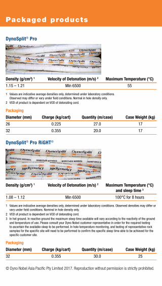
headline
© Dyno Nobel Asia Pacific Pty Limited 2017. Reproduction without permission is strictly prohibited.
Packaged products
Density (g/cm3) 1 Velocity of Detonation (m/s) 2 Maximum Temperature (°C)
1.15 – 1.21 Min 6500 55
1 Values are indicative average densities only, determined under laboratory conditions. Observed may differ or vary under field conditions. Normal in hole density only.
2 VOD of product is dependent on VOD of detonating cord.
Packaging
Diameter (mm) Charge (kg/cart) Quantity (m/case) Case Weight (kg)
26 0.225 27.0 17
32 0.355 20.0 17
Density (g/cm3) 1 Velocity of Detonation (m/s) 2 Maximum Temperature (°C) and sleep time 3
1.08 – 1.12 Min 6500 100°C for 8 hours
1 Values are indicative average densities only, determined under laboratory conditions. Observed densities may differ or vary under field conditions. Nominal in hole density only.
2 VOD of product is dependent on VOD of detonating cord.3 In hot ground. In reactive ground the maximum sleep time available will vary according to the reactivity of the ground
and temperature of use. Please consult your Dyno Nobel customer representative in order for the required testing to ascertain the available sleep to be performed. In hole temperature monitoring, and testing of representative rock samples for the specific site will need to be performed to confirm the specific sleep time able to be achieved for the specific customer site.
Packaging
Diameter (mm) Charge (kg/cart) Quantity (m/case) Case Weight (kg)
32 0.355 30.0 25
DynoSplit® Pro
DynoSplit® Pro RiGHT®

© Dyno Nobel Asia Pacific Pty Limited 2017. Reproduction without permission is strictly prohibited.
Packaged products
POWERMITE PLUS®
Typical Density Energy Relative Weight Relative Bulk VOD
(g/cm3) (MJ/kg) 1 Strength (%) 1 Strength (%) 1 (m/s) 2
1.15 3.81 103 145 4900 – 5300
1 All Dyno Nobel energy values are calculated using a proprietary Dyno Nobel thermodynamic code. Other programs may give different values. The values given are relative to ANFO at 0.82 g/cm3.
2 VOD is dependent on product density, diameter, the degree of confinement and other factors.
Packaging
POWERMITE PLUS Cart Weight (kg) Chubs per case
76mm x 400mm 20 kg 20
Diameter Charge VoD Maximum case (mm) (kg/m) weight (kg)
29 0.50 6500 25
Packaging Length Quantity per case Length per case3.0 m 12 363.5 m 10 35
Z-BAR®

© Dyno Nobel Asia Pacific Pty Limited 2017. Reproduction without permission is strictly prohibited.
Packaged products
Typical density Theoretical energy comparison VoD (g/cm3) Energy (MJ/kg) RWS RBS (m/s)
1.16 – 1.23 <= 32mm 2.78 121 183 3400 >= 45mm 2.72
Packaging Quantity Average cartridge Case per 25kg case weight (g) weight kg32mm x 200mm 135 185 25
32mm x 700mm 34 736 25
55mm x 400mm 33 758 25
65mm x 400mm 21 1190 25
80mm x 400mm 15 1670 25
POWERMITE® PRO
Nominal Energy Relative Relative Bulk VOD Sensitivity Detonation Density (MJ/kg) 1 Weight Strength (m/s) 2 Pressure 3
(g/cm3) Strength (%) 1 (%) 1
1.15 – 1.21 3.60 96 138 5400 8g/m det cord 8.6
1 All Dyno Nobel energy values are calculated using a proprietary Dyno Nobel thermodynamic code. Other programs may give different values. The values given are relative to ANFO at 0.82 g/cm3.
2 VOD is dependent on product density, diameter, the degree of confinement and other factors.
3 Calculated using an ideal thermodynamic code.
Packaging Cart Weight (kg) Chubs per case
540 x 336 x 240mm 25 kg 41
POWERMITE THERMO®

© Dyno Nobel Asia Pacific Pty Limited 2017. Reproduction without permission is strictly prohibited.
Initiation systems – downhole
NONEL MS Series
NONEL MS HD Series
Delay Clip Nominal firing Time betweenperiod (ms) colour time (ms) delays (ms)1 Red 25 252 Blue 50 253 Brown 75 254 Orange 100 255 Aqua 125 256 Gold 150 257 Lime Green 175 258 Pink 200 259 Dark Green 225 2510 Purple 250 2511 Light Blue 275 2512 Light Green 300 2513 Mauve 325 2514 Mustard 350 2515 Crimson 375 2516 Yellow 400 2517 Dark Blue 425 2518 Green 450 2519 Orange 475 2520 White 500 2521 Rubine Red 550 5022 Grey 600 5023 Black 650 5024 Brown 700 5025 Red 750 5026 Blue 800 5027 Brown 900 10028 Orange 1000 100
Packaging Winding ConfigurationLength (m) Units per case Standard Heavy Duty4.8 200 Coiled n/a6.0 150 Coiled Coiled7.2 150 Coiled Coiled9.0 120 Figure 80 Figure 8012.0 90 Figure 80 Figure 8015.0 75 Figure 80 Figure 8018.0 60 Figure 80 Figure 8024.0 40 n/a Figure 8030.0 30 n/a Spooled36.0 30 n/a Spooled45.0 30 n/a Spooled60.0 30 n/a Spooled80.0 30 n/a Spooled
NONEL® tube: Standard Heavy DutyColour Red OrangeDiameter 3.0mm Detonator # 12 Strength
NONEL® MS Series

© Dyno Nobel Asia Pacific Pty Limited 2017. Reproduction without permission is strictly prohibited.
Initiation systems – downhole
Delay Clip Nominal firing Time between period (ms) colour time (ms) delays (ms)0 White 25 251 Red 500 4752 Blue 800 3003 Brown 1100 3004 Orange 1400 3005 Aqua 1700 3006 Gold 2000 3007 Lime Green 2300 3008 Pink 2700 4009 Black 3100 40010 Purple 3500 40011 Light Blue 3900 40012 Dark Green 4400 50013 Mauve 4900 50014 Mustard 5400 50015 Crimson 5900 50016 Yellow 6500 60017 Dark Blue 7200 70018 Green 8000 800
Packaging
Length (m) Units per case Winding configuration4.8 200 Coiled5.4 180 Sidewinder6.0 150 Coiled7.2 150 Coiled
NONEL tube: StandardColour YellowDiameter 3.0mmDetonator # 12 Strength
NONEL® LP Series

© Dyno Nobel Asia Pacific Pty Limited 2017. Reproduction without permission is strictly prohibited.
Initiation systems – open-cut
Delay period (ms) Clip colour0 Green9 Violet17 Yellow25 Red42 White67 Blue109 Black150 Dark Green176 Orange200 Gold
Packaging
Length (m) Units per case Winding configuration4.8 150 Figure 806.0 140 Figure 807.2 125 Figure 809.0 100 Figure 8012.0 80 Figure 8015.0 70 Figure 8018.0 50 Figure 80
Tube colour YellowDetonator Low strengthCapacity 6 tubes
NONEL® EZTL Series

© Dyno Nobel Asia Pacific Pty Limited 2017. Reproduction without permission is strictly prohibited.
Initiation systems – open-cut
Delay period (ms) Clip colour17 Yellow25 Red42 White67 Blue109 Black176 Orange
Packaging Units per case 200
Tube Standard Orange
NONEL® Lead Line 1000 Reel-off initiation system (no detonator) Length 1000m (two per case)VOD 2100m/sec (+/- 300)Tube Standard Yellow
NONEL® Starter Packaging Length (m) Units per case Winding configuration100 16 Spooled300 4 Spooled500 4 Spooled
Tube Standard Yellow
NONEL® MS Connector

© Dyno Nobel Asia Pacific Pty Limited 2017. Reproduction without permission is strictly prohibited.
Nominal Diameter Length Units per Priming weight (mm) (mm) case (g)
TROJAN® SPARTAN 150 150 36 119 48 Detonator sensitive
TROJAN® SPARTAN 400 400 55 119 20 Detonator sensitive
TROJAN® TWINPLEX 450 57 117 36 Detonator sensitive
TROJAN® NBU 400 400 55 119 20 Primacord 5
TROJAN® RINGPRIME® 250 46 175 42 Detonator sensitive
NB: Spiders for RINGPRIME® have 125mm diameter and come in separate 70 unit lots.
Initiation systems
TROJAN SPARTAN TROJAN TWINPLEX
Cast Boosters
TROJAN NBU TROJAN RINGPRIME
Core load Diameter Minimum Packaging (g/m) (mm) strength (kg)
PRIMACORD® 5 5.6 4 68 2 x 500m rolls
PRIMALINE® 10 10.6 5 68 2 x 350m rolls
PRIMALINE® 8HT 8.5 4.7 45 2 x 305m rolls
FIRELINE® 8/40 RDX 8.6 4.3 68 2 x 305m rolls
PRIMACORD 5
Detonating Cords
PRIMALINE 10 PRIMALINE 8HT FIRELINE 8/40 RDX

© Dyno Nobel Asia Pacific Pty Limited 2017. Reproduction without permission is strictly prohibited.
Initiation systems
ELECTRIC SUPER STARTER™
Description
Delay time (ms) 0
Fuse Head resistance (ohm) 1.92
Firing current, minimumrecommended, (A)
Series wiring 3 amps AC or 1.5 amps DC
Parallel wiring 1 amp AC or DC per detonator
Series-in-parallel wiring 2 amps AC or DC per series
Leg wires (m) 3.5
Strength (#) 10
The maximum recommended continuous firing current is 10 amps per detonator.
BlastWeb® Electronic Initiation System
BlastWeb Initiation System is a Centralised Blasting System specifically designed for underground blasting operations.
The BlastWeb system can be used to fire SmartShot and DriftShot Starter electronic detonators.
Properties
Temperature Limits -10°C to +50°CPower Supply 110V; 220V; 525VBattery User replaceable/ rechargeable 12V 7.2Ah sealed lead acid batteryWeight ±50KgDimensions L = 539-541mm; W = 480-482mm; H = 731-733mmExternal Connectors SmartKey; USB; (RS-232 & RS-485 for expansion – rear of unit)Water Resistance Splash proof (IP64)

© Dyno Nobel Asia Pacific Pty Limited 2017. Reproduction without permission is strictly prohibited.
Initiation systems
SmartShot® Electronic Initiation System
The SmartShot system offers innovative features including wireless remote blasting and complete timing flexibility. Specialised waterproof and dirt displacing connectors ensure quick, easy and reliable connections and prevent leakage.
PackagingLength (m) Units per case
10x7 18
20x10 18
25x0.2 18
35x0.2 15
45x0.2 12
60x0.2 8
DriftShot® Starter Electronic Initiation System
The DriftShot Starter is an electronically initiated detonator intended for the remote firing of detonating cord, generally from the BlastWeb Centralised Blasting System
PackagingLength 2m
Unit/Case 100 (2 x 1 to 50)
PropertiesTensile Strength 374N
System Operating -20°C to +80°C
Temperature (range)
Detonator Strength #12

© Dyno Nobel Asia Pacific Pty Limited 2017. Reproduction without permission is strictly prohibited.
Initiation systems
DigiShot® Plus Electronic Initiation System
DigiShot Plus is truly flexible, user friendly and fully programmable. Additional features include remote firing capability, tag-on-connect and the ability to initiate up to 9,600 detonators.
Properties
Tensile Strength 400NSystem Operating Temperature (range) -20°C to +80°CMaximum Delay 20,000 millisecondsMaximum Detonators per Blast 9,600 (synchronised 4 x Bench Boxes)
Length (m) Units per case 18 5224 4030 3237 2446 2055 1675 16
DigiShot® Plus.4G
The DigiShot Plus.4G system comprises the new 4G detonator with increased memory, and the Blast Commander which is used as a Base, Bench or Repeater device. Available in two wire configurations – standard and premium XTM which features extreme impact resistance and tensile strength. The CE4 Tagger is used on bench for testing and tagging.
PackagingLength (m) Standard Wire XTM Wire Units per case Units per case
18 52 coils 52 coils
24 40 coils 40 coils
30 32 coils 32 coils
36 24 coils 24 spools
46 20 coils 18 spools
55 16 coils 18 spools
75 16 coils 12 spools

© Dyno Nobel Asia Pacific Pty Limited 2017. Reproduction without permission is strictly prohibited.
Blasting accessories
DYNOSTART™ (DS2)
DYNOSTART is a battery powered electronic blasting
machine for initiation of NONEL® tube. Electrical energy is
converted into a strong shock wave of high temperature
that, when applied inside a NONEL tube by the means
of an electrode, initiates the tube. DYNOSTART uses a
common 9V battery and a durable electrode. Both battery
and electrode are easy to change. The electrode can be
removed from the blasting machine at any time to prevent
unauthorised usage. DynoStart is designed to require the
use of both hands when initiating the blast. This is to avoid
unintentional firing of a blast.
DYNOTRACKER™
The DYNOTRACKER is a device that attaches to the end
of a standard charging hose used for loading ANFO. This
device allows the use of ANFO as a perimeter charge in
tunnelling applications, hereby eliminating the need for
more expensive cartridged explosives.
NONEL® Starter Gun
The NONEL Starter Gun is a simple and highly effective
hand held blasting machine, robustly constructed
from metal alloys and stainless steel. It has an integral
safety device and uses Shot Shell Primers No. 20 as
primer caps. It is a complete blasting machine, no other
equipment being needed to initiate a NONEL tube.

© Dyno Nobel Asia Pacific Pty Limited 2017. Reproduction without permission is strictly prohibited.
Blasting accessories
STINGER EXPLODER™ 10 Shot
The SB10 is a compact capactive discharge exploder.
The unit is powered by 1.5V AA batteries. A removable
magnetic key controls security of the firing mechanism
and a push button operates the firing circuit. A ready light
illuminates when the firing capacitor is fully charged.
Lo-Stat ANFO Hose
The Lo-Stat ANFO Hose is a conductive thermoplastic tube used for delivery of explosives in
underground applications.
Description Product specification
20mm hose 25mm hose
Internal Diameter 18.4mm – 19.6 mm 24.6mm – 25.4 mm
Outside Diameter 26.4mm – 27.6 mm 29.8mm – 30.2 mm
Wall Thickness 3.7mm – 4.4 mm 2.3mm – 2.7 mm
Resistance/m metre 15 – 25 KΩ 15 – 25 KΩTotal Resistance (whole coil) <1.6 MΩ <1.6 MΩNominal Weight 330-370 g/m 210-230 g/m

© Dyno Nobel Asia Pacific Pty Limited 2017. Reproduction without permission is strictly prohibited.
Blasting accessories
STEMPAC™
The STEMPAC is a stemming device constructed using Stemtite blast control plugs and
crushed aggregate in a sealed plastic package. The STEMPAC enables blastholes that have
been drilled horizontal or at an angle above horizontal to be stemmed. It is designed to be
placed in a blasthole after the loading has been completed and be located 80cm below the
explosive column. STEMPAC is available in three (3) different diameter sizes – 76mm, 89mm
and 102mm.
Twin Twist Bell Wire
Insulation colour Red and White Twist
Roll size 500 metres
Number of cores 2
Current rating (A) 1.8
Electrical Resistance @ 20°C(mΩ/m) per core 62

TITAN 9000xero has been developed to provide a practical and reliable
solution for reducing post blast fume in wet/damp, soft or fractured ground
conditions. For more information contact your Dyno Nobel representative,
visit www.dynonobel.com or call 1800 251 872

Dyno Nobel Asia Pacific
QueenslandPrincipal Place of Business282 Paringa RoadGibson IslandMurarrie Qld 4172Australia PO Box 3559Tingalpa DC Qld 4173AustraliaTelephone: +61 7 3026 3900Fax: +61 7 3026 3999
New South WalesMt Thorley Technical Centre 5 Woodland Road Mt Thorley NSW 2330 Australia PMB 17Singleton NSW 2330AustraliaTelephone: +61 2 6574 2500Fax: +61 2 6574 6849
Western AustraliaPerth Office Suite 3, Level 2Eastpoint Plaza233 Adelaide TerracePerth WA 6000AustraliaTelephone: +61 8 6188 3000Fax: +61 8 9325 4910
IndonesiaJakarta Office PT. dnx Indonesia Park View Plaza, 1/FJl. Taman Kemang 2 No. 27JakartaIndonesia 12730Telephone: +62 21 7179 4791Fax: +62 21 7179 4794
Papua New GuineaFor PNG enquiries, contact the Gibson Island, Brisbane office.
www.dynonobel.com