EXPERIMENTAL STUDY ON THE RESPONSE OF SEISMICALLY …
17
EXPERIMENTAL STUDY ON THE RESPONSE OF SEISMICALLY ISOLATED MASONRY INFILLED STEEL FRAMES DURING THE INITIAL STAGES OF A SEISMIC MOVEMENT FRANCISCO J. PALLARÉS, LUIS PALLARÉS ICITECH – Instituto de Ciencia y Tecnología del Hormigón Universitat Politécnica de Valéncia c/ Camino de Vera s/n, 46022 Valencia, Spain e-mail: [email protected] e-mail: [email protected] Keywords: Masonry Infill, seismic isolation, steel frame, in-plane behavior, seismic isolator. Abstract. A novel seismic isolator is presented to detach the structural behavior from the infill effect during earth movements, with the aim of avoiding strong interactions. An experimental campaign was carried out to determine the influence of this isolator during the early stages of the seismic response of masonry-infilled steel frames, testing different configuration schemes to assess their effectiveness in terms of overall isolation, reduction of peak loads, strain levels and energy dissipation. The device was found to hinder the formation of the damaging diagonal compression struts by absorbing the relative displacements between frame and infill. The results achieved show that seismic interaction between infill panels and the structural skeleton can be faced from an isolation point of view. 1 INTRODUCTION Clay brick or concrete block masonry is used to build walls that provide good thermal and sound insulation, and resistant capacities. As it is easy to install and light enough to be carried around the building site, it is one of the most frequently used materials for curtain walls in the openings between reinforced concrete or steel frames in building construction. In this form and without any reinforcement, it is considered as a non-structural element by many international Standards [1, 2, 3, 4, 5] and so is ignored in the calculations. This is quite realistic when only gravity loads are taken into account, but could be a grave shortcoming when dynamic loads are considered, as many research groups have been pointing out for some time [6, 7, 8]. Masonry panels stiffen the structure against seismic loads and modify building’s strength, damping, hysteretic behavior and deformation capacity. For example, El - Dakhakhni et al. [8] proposed a strut model for masonry-infilled steel frames in an attempt to take into account the important effect of masonry panels in a structure’s seismic response. These authors point out the complexity of the problem, since total or partial panel failure may
Transcript of EXPERIMENTAL STUDY ON THE RESPONSE OF SEISMICALLY …

EXPERIMENTAL STUDY ON THE RESPONSE OF SEISMICALLY
ISOLATED MASONRY INFILLED STEEL FRAMES DURING THE
INITIAL STAGES OF A SEISMIC MOVEMENT
FRANCISCO J. PALLARÉS, LUIS PALLARÉS
ICITECH – Instituto de Ciencia y Tecnología del Hormigón
Universitat Politécnica de Valéncia
c/ Camino de Vera s/n, 46022 Valencia, Spain
e-mail: [email protected]
e-mail: [email protected]
Keywords: Masonry Infill, seismic isolation, steel frame, in-plane behavior, seismic isolator.
Abstract. A novel seismic isolator is presented to detach the structural behavior from the
infill effect during earth movements, with the aim of avoiding strong interactions. An
experimental campaign was carried out to determine the influence of this isolator during the
early stages of the seismic response of masonry-infilled steel frames, testing different
configuration schemes to assess their effectiveness in terms of overall isolation, reduction of
peak loads, strain levels and energy dissipation. The device was found to hinder the formation
of the damaging diagonal compression struts by absorbing the relative displacements between
frame and infill. The results achieved show that seismic interaction between infill panels and
the structural skeleton can be faced from an isolation point of view.
1 INTRODUCTION
Clay brick or concrete block masonry is used to build walls that provide good thermal and
sound insulation, and resistant capacities. As it is easy to install and light enough to be carried
around the building site, it is one of the most frequently used materials for curtain walls in the
openings between reinforced concrete or steel frames in building construction.
In this form and without any reinforcement, it is considered as a non-structural element by
many international Standards [1, 2, 3, 4, 5] and so is ignored in the calculations. This is quite
realistic when only gravity loads are taken into account, but could be a grave shortcoming
when dynamic loads are considered, as many research groups have been pointing out for some
time [6, 7, 8]. Masonry panels stiffen the structure against seismic loads and modify
building’s strength, damping, hysteretic behavior and deformation capacity. For example, El-
Dakhakhni et al. [8] proposed a strut model for masonry-infilled steel frames in an attempt to
take into account the important effect of masonry panels in a structure’s seismic response.
These authors point out the complexity of the problem, since total or partial panel failure may

2
cause the sudden transfer of seismic forces to other parts of the structure, while admitting that
no realistic analytical models are available.
Recent earthquakes in Spain (Lorca, 2011) [9] and other parts of the world [10] have made
it clear that non-structural masonry plays an important role in the seismic behavior of framed
buildings [11, 12, 13] and can help to reduce economic losses and human casualties (Fig. 1).
References [14, 15, 16, 17] point out this role when study the response of buildings in Lorca
earthquake. These non-structural elements can induce damage to structural elements under
seismic loads (ends of beams and columns) leading to failure mechanisms, as has occurred in
Lorca and many earthquakes.
Figure 1: Building failure in Lorca earthquake (Spain, 2011)
There are two main approaches to the problem of masonry infills in building design: [18,
19, 20] a) consideration, b) isolation.
The former approach takes masonry walls into account in the seismic design, which are
usually strengthened to consider the interacting structural infill influencing the seismic
response. Different methods have been used to model the phenomenon, including: elastic
theory, plastic theory, limit state and equilibrium, finite elements using macro- and micro-
modeling for masonry, experimental formulae, etc., and many references from many years
ago to present can be found in the scientific literature related to this approach: e.g. tying walls
[21, 22], concrete jacketing of walls [23], epoxy and cementitious fiber composites [24, 25,
26, 27, 28, 29], prestressing techniques [30], or design of new units [31, 32]. However, these
methods and techniques are sometimes rather complex and difficult to replicate without the
help of precise numerical models able to reproduce a building’s actual behavior. Furthermore,
the interaction also varies during the course of the seismic action, thus complicating the
design even further. Nevertheless, the interaction between the building structure and non-
structural masonry is usually studied from the resistance point of view by including the non-
structural panels in the resistant elements. Together with the fact that masonry panels are

3
considered as non-structural elements and can be freely moved around in the architectural
design, this would invalidate any analytical consideration. For these reasons the authors
focused on the second approach to the problem of interaction: isolation.
Regarding this second approach, of the different techniques that can be used to isolate a
masonry panel from the building’s structural skeleton, one of the most obvious is to fill the
joint between frame and panel with a flexible strip. However, the main drawback to this
technique is that it is not advisable to have a soft joint at the base of the panel, besides the fact
that a flexible joint around the frame would reduce the panel’s out-of-plane performance.
A big step towards a practical solution to isolating masonry panels and frames would be
obtained if it were possible to design a connection able to provide flexibility through the in-
plane behavior and stiffness through the out-of-plane behavior. Although this has already
been pointed out many times in the scientific literature, as far as the authors are aware, no
practical commercial systems have as yet been developed to isolate the resisting skeleton from
the non-structural masonry walls.
A number of different solutions have been suggested by several research groups in this
field; e.g. [33, 34] developed a steel sub-frame attached to the steel building frame. Basically,
this subframe is made of vertical and horizontal steel members and a special piece acting as a
‘fuse’ separates the infill from the structure in case of large lateral forces. Markulak et al. [35]
studied the behavior of steel frames infilled with masonry, introducing special perforated
blocks and lightweight autoclaved aerated concrete blocks that allowed partial separation of
the masonry from the frame to limit combined frame-infill action. Others have proposed the
use of different materials, e.g. polymers [36], to avoid structural interaction between frame
and infill or enhancement properties.
Other references about base isolation of masonry buildings can be found [37, 38, 39], but
they are not specifically related to panels’ seismic isolation. In the same sense, the works [40,
41] can be referenced here. The former introduced a visco-elastic material (lead) between
beam and the top layer of the masonry wall in an attempt to isolate the restraint introduced by
the wall on to the columns when these creep in the long term. Beside, these authors performed
in-plane tests to confirm that the lead layer did not have adverse effects on the specimens. The
latter work shows tests performed using a ‘frictional sliding fuse’, which is a device
composed of steel plates that divides the infill into two parts by a horizontal layer, allowing
sliding in longitudinal direction before infill crushing but restraining transversal movements.
The device can be regulated to adjust strength and ductility.
Since few references can be found related to seismic isolation of masonry panels, the
authors decided to carry out some research themselves in this important field. In the following
sections it is described the result in the form of a new product intended to solve the problems
that arise when retrofitting masonry panels that have not been seismically isolated.
This paper thus proposes an experimental procedure designed to test a novel seismic
isolation device conceived to separate the dynamic response of the building from the
influence of its masonry walls, in an attempt to shed some light on the field of seismic

4
isolation. Experiments were carried out to evaluate the energy dissipation, peak load,
hysteretic curves and strain levels of isolated infilled frames under small displacements before
the onset of visual damage to panels and frames. In this way the authors thought it would be
possible to determine the behavior of the structure during the initial phases, close to the elastic
range and compare the actual response with the predicted response in the design phase of the
bare structure, in which the infills are not usually considered.
2 SEISMIC ISOLATOR FOR MASONRY PANELS
It is clear that one of the main phenomena affecting the seismic response of frame
buildings infilled with masonry panels is the formation of diagonal compression struts (e.g.
FEMA 273 [42].
As a consequence of horizontal displacements, when there is drift between different floors,
a resisting mechanism known as a ‘diagonal compression strut’ appears to resist the seismic
loads. This mechanism often causes damage to the ends of beams and columns and to
masonry panels, as can be observed in the simplified sketch in Fig. 2. This phenomenon also
occurs in partially infilled frames, in which the panel reduces the effective length of the
columns, leading to unexpected failures.
Figure 2. Formation of diagonal compression struts and damage.
These diagonal compression struts are used to account for the contribution of the masonry
panel when modeling infilled frames; however the way in which the infill and frame interact
is not clear, so that it is difficult to explain the complex behavior exhibited by panels under
seismic movements.
Since no practical models have yet been developed to properly consider the panels in the
computations, and since infills are considered as non-structural and can be added or removed
from the structure by the tenants, the present authors opted to aim their efforts towards the
isolation philosophy.
5
In tests carried out at the Universitat Politècnica de Valéncia, the authors initiated research
on a novel device and achieved a high degree of structural independence between the seismic
response of the building structure and the influence of the masonry infill. The purpose of this
device is to act as a seismic isolator in a way that allows the structural frames to deform
without being affected by the high stiffness introduced by the masonry panels.
The SISBRICK seismic isolator (Figure 3a) is similar to a normal brick in shape and size
and is made of a deformable matrix with an elastic modulus a few orders of magnitude
smaller than commercial bricks, able to allow movements in one direction, and contain a steel
frame able to withstand forces in the two perpendicular directions. Installed at the corners of
the frame, it can absorb the relative movements induced by the structure, increasing out of
plane resistance and hindering the formation of diagonal compression struts. Figure 3b shows
the compression test performed on the deformable matrix material, with an elastic modulus of
15 MPa and elastic behavior in a wide range of strain. The material used in the tests is
polyurethane, but any material accomplishing this mechanical characteristic would be valid
from a seismic point of view. The steel frame is made of reinforcement bars B500S with 6mm
diameter, not all of them fully crossing the matrix to allow for deformability.
Figure 3. a) Installation of SISBRICK seismic infill; b) Elastic modulus.
Figure 4 shows results of the compression tests performed on both normal and seismic
isolator bricks in accordance with UNE-EN 772-1 standards. The higher degree of
deformability of the isolator over normal bricks can be clearly seen. The bricks measure
329mm x 69mm x 155mm.

6
Figure 4. Compression tests on conventional and the proposed SISBRICK bricks.
The purpose of the tests described below was to compare the performance of this device in
terms of energy dissipation and the adequacy of different isolation schemes.
3 TEST LAYOUT
A comprehensive series of experiments were performed to test the effects of the
SISBRICK seismic isolator in cyclic movements in a number of different configurations.
Eleven tests (four with the same configuration scheme) were performed on a steel frame.
The tests were divided into two types: small amplitude cycles and large amplitude cycles. The
seismic isolator bricks were placed between frame and infill and can be identified by their
distinctive color.
Tables 1 and 2 summarize these tests:
Bare frame
Conventional infill (MM0)
Layout 1 (MM1)

7
Layout 2 (MM2) Layout 3 (MM3)
Layout 4 (MM4)
Layout 5 (MM5)
Table 1. Isolation Schemes tested
Infill scheme Small Large
Bare frame X X
Conventional infill MM0.1, MM0.2 X X
Layout 1 MM1 X
Layout 2 MM2.1, MM2.2 X X
Layout 3 MM3.1, MM3.2 X X
Layout 4 MM4 X
Layout 5 MM5 X
Table 2. Tests carried out.
The schemes ranged from full isolation (MM5) to minimum isolation at the corners (MM2),
top (MM3) or sides (MM4).
All these configurations were tested on a 2960x1750 mm (center line) steel frame, made of
IPE160 shaped beams in S275 structural steel, clamped at the corners and pinned to ground,
as can be seen in Figure 5.

8
Figure 5. Steel frame used in the tests (units in mm).
The cyclic load was applied to the top right-hand corner by a hydraulic jack clamped to a
reaction wall. The jack was able to apply a 1200 kN pushing load and 500 kN pulling load,
with a total length of 500 mm in cyclic movements.
The specimens were instrumented to record stress paths and deformation in the panel and
frame to identify the diagonal strut and compare the results with those from the seismic
isolator. Figure 6 shows the location of the LVDT sensors on the outside of the frame to
measure deformation. LVDT sensors were also placed on the contact between frame and
panel to measure the gap between the top beam and column. Seven groups of three LVDT
sensors were placed at different points on the panel to register deformations in bricks and
joints. Ten groups of three strain gauges were set to measure deformations in bricks at
particular points.
LVDT sensors were also placed on the reacting wall, ground and joints to control possible
relative movements of the frame.
Six high resolution cameras were set to collect information on the deformation of the
specimens during the tests.

9
Figure 6. Instrumentation used in the tests (units in mm).
To check the performance of the tests, the data acquisition system permitted real-time
display of the force-displacement cycles and the values recorded in strain gauges and
transducers.
The loading protocol was based on the recommendations proposed by FEMA 461 [43],
ACI 374 [44] and ATC 24 [45].
A theoretical model was performed for both a bare and conventional infilled frame to
estimate the ultimate load. A controlled displacement test was preferred, and the drift was
chosen as the control parameter for the imposed displacements. The yielding drift was
selected as 75% of the corresponding drift for the ultimate load, according to [44].
For the small displacement tests, as the authors wanted the frame to remain within the
elastic range, 50% of the yielding drift was chosen as maximum value in the loading protocol.
The increment of the deformation level was established by multiplying the yielding drift by
certain factors, which were: 0.25, 0.5, 0.75, 1, 1.5, 2.25, 3.38, 4, 6, 8, 10 and 12 for the large
displacement tests. When the tests were limited to the elastic range, the loading protocol was
defined as shown in Fig. 7.

10
Figure 7. Loading protocol for bare frame (left) and infilled frame (right).
Some tests (MM0.2, MM2.2, MM3.2, and MM5) had an initial step with small amplitude
to discard initial errors in the jack and test configuration.
An appropriate control of the test inputs and actuator parameters was achieved; the
velocities acquired by the actuator varied from 0.05 to 1 mm/s, making dynamic effects
negligible.
All tests were quasi-static and the deformation was incrementally and slowly applied in
stepwise reversed cycles. Two cycles at each amplitude were completed to know the stiffness
degradation at the same drift level.
4 EXPERIMENTAL RESULTS
The load-displacement hysteretic curves can be seen in Fig. 8 for specimens MM0.2 (no
isolation), MM5 (full isolation), and for the bare frame, which is a straight line for these
displacement levels. In this general overview, it can be seen that, for the same imposed
displacement, the applied force is almost 50% higher in the conventional infill than the
isolated one, validating the initial goal of the paper from the perspective of the isolation
philosophy.
Figure 8. Hysteretic curves between conventional infill (MM0.2 left) and ‘fully’ isolated
(MM5 right).
For the sake of clarity, only the hysteretic curves for the last step of the small displacement
series are shown (Step 10), where the influence of each configuration is clearer from the

11
cyclic isolation point of view. This can be seen in Fig. 8 and Table 1, where for the same
displacement (around 15 mm), the hysteretic curves and the ratios between the maximum
loads for each configuration compared to the conventional one (MM0.2) are:
Step 10 Mean Peak load (x10-1
kN) Ratio to MM0.2 Ratio to Bare
Bare 37.3
MM0.2 85.9 0% 230.3%
MM1 61.0 40.8% 63.5%
MM2.2 57.4 49.7% 53.9%
MM3.2 78.4 9.6% 210.2%
MM4 64.3 33.6% 72.4%
MM5 57.6 49.1% 54.4%
Table 1. Ratios between Peak loads for different isolation schemes compared to
conventional infill.
Figure 9. Hysteretic curves for Step 10.
It can be concluded that schemes MM5, MM2.2 and MM1 show a high level of isolation in
terms of maximum horizontal load, with interesting ratios compared to the bare frame and the
conventional infill. Scheme MM2.2 seems to catch the essence of the isolation mechanism,
hindering the formation of the diagonal strut and locating the isolators in particular positions
to reduce its consumption, becoming as a good candidate for practical purposes. Fig. 9 shows
this group of three closer to the bare branch.
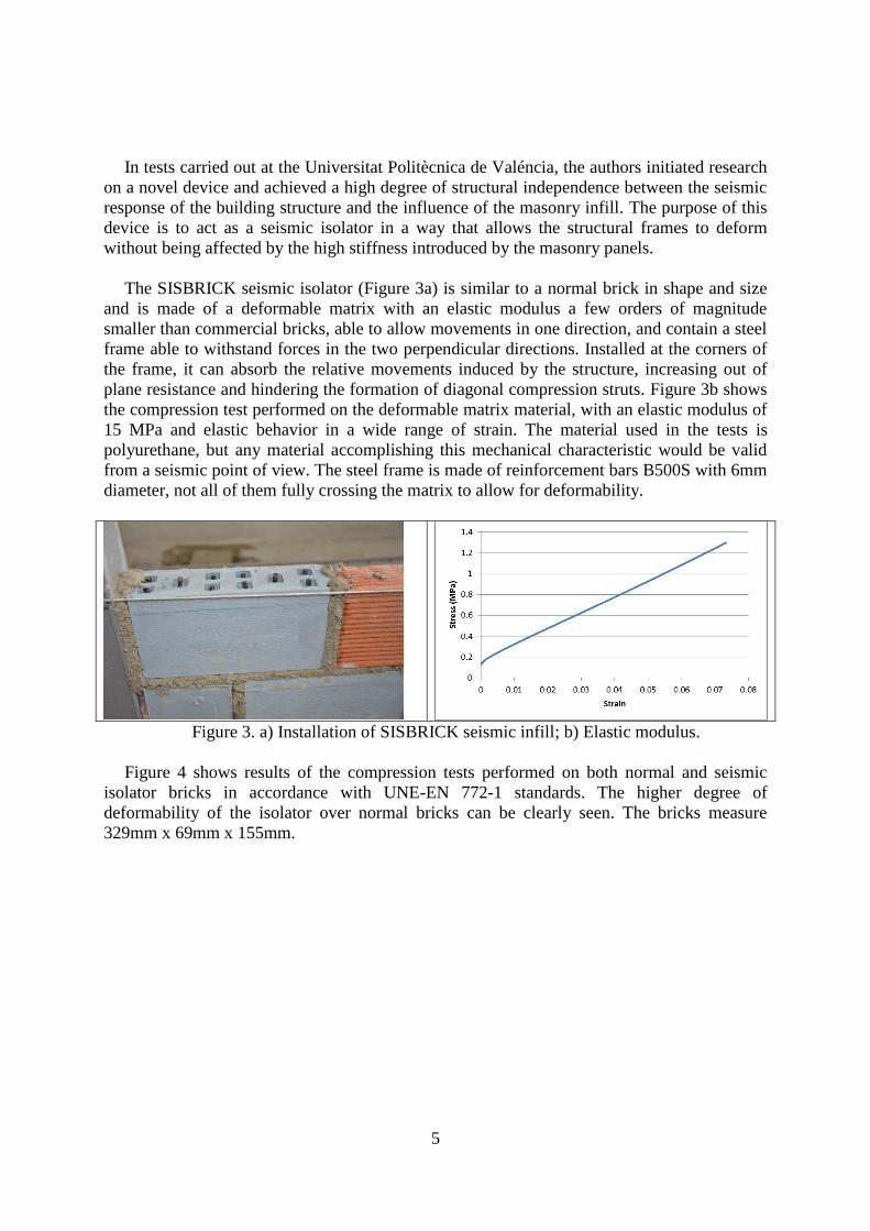
In terms of energy dissipation, the results were processed to obtain the energy dissipation
per cycle (each step has two cycles), the cumulative energy dissipation, and the ratio per cycle
between energy dissipation and energy input, giving the curves shown in Fig. 10:
12
Figure 10. a) Energy dissipation per cycle; b) Cumulative energy dissipation; c)
Cumulative Energy dissipation and Cumulative Energy input ratio.
From Fig. 10a, it is clear that scheme MM5 dissipates less energy per cycle than the others,
since it is supposed to be the most isolated one with the closest behavior to the bare elastic
frame. It thus has a higher capacity to return energy to the system from the isolators, avoiding
so much friction and damage to the bricks. It is also clear that the more isolated schemes
(MM5, MM2.2, MM1) dissipate less energy in small cycles, since the displacement is the
same but more flexible. The MM2.2 scheme validates its capacity as effective and least

13
consuming isolator scheme. This can also be seen in Fig. 10b, where these two schemes
dissipate the least cumulative energy of all the tests.
The MM0.2 specimen dissipates most energy per cycle in the very early stages, mainly by
cracking and friction. In Fig. 8 its non-linear behavior at these early low amplitudes can be
seen, with a change in the slope of the envelope. Something similar also happens in MM5, but
to a lesser extent.
The ratio between cumulative energy dissipation and cumulative energy input is shown in
Fig. 10c. It is interesting to see how schemes MM1 and MM2.2 have a large dissipative ratio
throughout all the cycles, while MM0.2, MM3 and MM5 seem to decrease. Scheme MM4
confirms the positive effect of column isolation.
A more comprehensive study about stresses and displacements developed inside the panels
is currently under development for a future work, together with additional tests. As a first
approximation, Fig. 11 displays on the top row strains captured by gauges in vertical direction
on points 4 and 5 (see Fig. 6) for specimens MM0 and MM1, while the bottom row shows
strains captured by gauges in horizontal direction. By the end of the experiment, reductions in
the strain levels around 65% and 85% are achieved for GH4 and GH5, while 75% and 85%
are achieved for GV4 and GV5, respectively (GH means horizontal gauge; GV means vertical
gauge). This exemplifies the effect of the isolator device on the formation of the diagonal
strut, reducing the interaction effect between frame and infill.
Figure 11. Top row: Strains in vertical direction in points 4 (left) and 5 (right). Bottom
row: Strains in horizontal direction in points 4 (left) and 5 (right).

14
5 CONCLUSIONS
A novel seismic isolator is proposed to detach the structural behavior from the infill effect
during earth movements, with the aim of avoiding strong interactions. An experimental
campaign was carried out to determine the influence of this isolator during the early stages of
the seismic response of masonry-infilled steel frames. Eleven different tests were carried out
on the seismic isolator in order to determine its efficiency in terms of overall isolation,
reduction of peak loads, strain levels and energy dissipation for different configuration
schemes. Load-displacement curves are presented for the most extreme cases to show the
validity of the isolation philosophy. A 50% reduction in the imposed horizontal force in some
configurations was achieved when using the seismic isolator for the same displacement
compared to the conventional infill.
All configurations are compared at the final step to know their isolation capacity, and
MM2.2 scheme becomes as a good candidate for practical purposes.
In terms of energy dissipation, results are shown for each configuration and step,
confirming again MM2.2 scheme as a good candidate for isolation.
Strain measurements on the wall are shown, obtaining reductions between 65% and 85%
when compared to conventional infill.
As regards hindering the formation of diagonal struts through isolation, the results confirm
this point. The isolator allows flexibility in the structure and a seismic response closer to the
design response, hindering the formation of the damaging diagonal compression struts by
absorbing the relative displacements between frame and infill.
Scheme M2.2 was seen to be a good isolation scheme for practical purposes to obtain good
results with few isolators for the different type of variables studied.
The results achieved thus show that seismic interaction between infill panels and the
structural skeleton can be approached from an isolation point of view. Practical solutions can
thus be designed and put on the market to avoid or reduce damage in columns and panels.
Further research is needed in this line and experiments are being conducted to go further into
this field. It is expected that the schemes under study will allow more energy to be dissipated
at larger amplitudes, since the integrity of the specimen is conserved for more cycles than
with conventional infill, due to the more close-to-‘elastic’ and flexible behavior in the initial
stages.
ACKNOWLEDGEMENTS
Authors want to express their gratitude to the Ministerio de Economía y Competitividad
from Spain (Spanish Ministry of Economy and Competitiveness) and FEDER from European
Commission for providing the financial support that made possible this study through the
research projects BIA2012-35186 and BIA2015-70651-R.

15
REFERENCES
[1] EN 1998. Eurocode 8: Design of structures for earthquake resistance. Part 1: General
Rules, seismic actions and rules for buildings. 1998.
[2] NCSE-02. Norma de construcción sismorresistente: parte general y edificación.
Ministerio de Fomento. 2002.
[3] NEHRP Recommended Provisions for Seismic Regulations for New Buildings and Other
Structures. 2009.
[4] INN 1996. Earthquake Resistant Design of Buildings (INN, 1996). Norma Chilena
Oficial NCh 433.Of1996 Modificada en 2009.
[5] NSR-10 Reglamento Colombiano de Construcción Sismo Resistente. Bogotá D.C.,
Colombia, Enero. 2010.
[6] Bertero V; Brokken S. “Infills in seismic resistant building”. Journal of Structural
Engineering, 109, 6. 2011.
[7] Negro P; Verzeletti G. “Effect of infills on the global behaviour of R/C frames: Energy
considerations from pseudodynamic tests”. Earthquake Engineering and Structural
Dynamics, 25. 1996.
[8] El-Dakhakhni WW; Elgaaly M; Hamid AA. “Three-Strut Model for Concrete Masonry-
Infilled Steel Frames”. Journal of Structural Engineering, 129, 2. 2003.
[9] Alarcón E; Benito M. Bulletin Earthquake Engineering (2014) 12: 1827.
doi:10.1007/s10518-014-9602-4. 2014.
[10] Jiang H; Liu X;Mao J. “Full-scale experimental study on masonry infilled RC moment-
resisting frames under cyclic loads”. Engineering Structures. Volume 91, 15 May, Pages
70–84. 2015.
[11] Ricci P; De Risi MT; Verderame GM; Manfredi G. “Influence of infill distribution and
design typology on seismic performance of low- and mid-rise RC buildings”. Bulletin of
Earthquake Engineering, 11(5), 1585-1616. http://doi.org/10.1007/s10518-013-9453-4.
2013.
[12] Gómez Martínez, F. FAST simplified vulnerability approach for seismic assessment of
infilled RC MRF buildings and its application to the 2011 Lorca (Spain) earthquake.
Universitat Politècnica de València. doi:10.4995/Thesis/10251/54780. 2015.
[13] Gómez-Martínez, F., Pérez-García, A., De Luca, F., Verderame, G. M. (2015).
Comportamiento de los edificios de HA con tabiquería durante el sismo de Lorca de
2011: aplicación del método FAST. Informes de la Construcción, 67(537): e065, doi:
http://dx.doi.org/10.3989/ic.12.110.
[14] De Luca F; Verderame GM; Gomez-Martinez F; Perez-Garcia A. “The structural role
played by masonry infills on RC building performances after the 2011 Lorca, Spain,
earthquake”. Bulletin of Earthquake Engineering, 12(5), 1999-2026.
http://doi.org/10.1007/s10518-013-9500-1. 2014.
[15] Hermanns L; Fraile A; Alarcón E; Álvarez R. “Performance of buildings with masonry
infill walls during the 2011 Lorca earthquake”. Bulletin of Earthquake Engineering,
12(5), 1977-1997. http://doi.org/10.1007/s10518-013-9499-3. 2014.
[16] Ruiz-Pinilla, J. G., Adam, J. M., Pérez-Cárcel, R., Yuste, J., & Moragues, J. J. (2016).
Learning from RC building structures damaged by the earthquake in Lorca, Spain, in

16
2011. Engineering Failure Analysis, 68. http://doi.org/10.1016/j.engfailanal.2016.05.013
[17] Romão, X., Costa, A. A., Paupério, E., Rodrigues, H., Vicente, R., Varum, H., & Costa,
A. (2013). Field observations and interpretation of the structural performance of
constructions after the 11 May 2011 Lorca earthquake. Engineering Failure Analysis, 34,
670-692. http://doi.org/10.1016/j.engfailanal.2013.01.040.
[18] Pallarés L; Pallarés FJ. “Structural Interaction between frames and infill masonry walls
subjected to lateral loads: a review”. Computational Techniques for Civil and Structural
Engineering. Saxe-Coburg Publications. 2015. CSETS 38, 345-366.
[19] Paulay T; Priestley MJN. Seismic design of reinforced concrete and masonry buildings.
John Wiley&Sons, Inc. 1992.
[20] Tomazevic. “Earthquake-Resistant Design of Masonry Buildings. Series on Innovation in
Structures and Construction” – vol. 1 Eds EaD, editor. London: Imperial College Press;
1999.
[21] Benedetti, D., Carydis, P. and Pezzoli, P., 1998. “Shaking table tests on 24 simple
masonry buildings,” Earthquake Engineering and Structural Dynamics, Vol. 27(1), pp.
67-90.
[22] Wang C; Forth JP; Nikitas N; Sarhosis V. “Retrofitting of masonry walls by using a
mortar joint technique; experiments and numerical validation”. Engineering
Structures.Volume 117, 15 June, Pages 58–70, 2016
[23] Maldonado NG; Olivencia LA. “Techniques used to repair seismic-resistant masonry
walls," Proceedings of the 10th World Conference on Earthquake Engineering, Madrid,
A.A. Balkema, Rotterdam, Vol. 9, pp. 5389-5394, 1992.
[24] Schwegler, G. “Masonry construction strengthened with fiber composites in seismically
endangered zones,” Proceedings of the 10th European Conference on Earthquake
Engineering, A.A. Balkema, Rotterdam, Vol. 3, pp. 2299-2303, 1995.
[25] El-Dakhakhni WW; Hamid AA; Elgaaly M. “Seismic retrofit of masonry infill walls
using advanced composites.” 13th World Conference on Earthquake
Engineering,Vancouver, B.C., Canada August 1-6, Paper No. 3093. 2004.
[26] Kalali A; Kabir MZ. “Experimental response of double-wythe masonry panels
strengthened with glass fiber reinforced polymers subjected to diagonal compression
tests”. Engineering Structures. Volume 39, June, Pages 24–37. 2012.
[27] Konthesingha KMC; Masia MJ; Petersen RB; Mojsilovic N; Simundica G; Page AW.
“Static cyclic in-plane shear response of damaged masonry walls retrofitted with NSM
FRP strips – An experimental evaluation”. Engineering Structures. Volume 50, May,
Pages 126–136. 2013.
[28] Ismail N; Ingham JM. “In-plane and out-of-plane testing of unreinforced masonry walls
strengthened using polymer textile reinforced mortar”. Engineering Structures. Volume
118, 1 July, Pages 167–177. 2016.
[29] Dehghani A; Fischer G; Alahi FN. “Strengthening masonry infill panels using engineered
cementitious composites”. Materials and Structures. January, Volume 48, Issue 1, pp
185–204, 2015.
[30] Yang KH; Joo DB; Sim JI; Kang JH. “In-plane seismic performance of unreinforced
masonry walls strengthened with unbonded prestressed wire rope units”. Engineering
Structures.Volume 45, December, Pages 449–459, 2012.

17
[31] Lourenço PB; Vasconcelos G;Medeiros P; Gouveia J. “Vertically perforated clay brick
masonry for loadbearing and non-loadbearing masonry walls”. Construction and Building
Materials. Volume 24, Issue 11, November, Pages 2317–2330, 2010.
[32] Silva L; Vasconcelos G; Lourenço P; Akhoundi F. “Experimental evaluation of a
constructive system for earthquake resisting masonry enclosure walls”. Brick and Block
Masonry – Trends, Innovations and Challenges – Modena, da Porto & Valluzzi (Eds).
2016.
[33] Aliaari M; Memari AM. Analysis of masonry infilled steel frames with seismic isolator
subframes. Engineering Structures 27. 2005. 487–500.
[34] Aliaari M; Memari AM. “Experimental Evaluation of a Sacrificial Seismic Fuse Device
for Masonry Infill Walls”. Journal of Architectural Engineering, Vol. 13, No.2, June 1,
2007.
[35] Markulak D; Radic I; Sigmund V. “Cyclic testing of single bay steel frames with various
types of masonry infill”. Engineering Structures, 51. 2013. 267–277.
[36] Aref A; Jung W. “Energy-Dissipating Polymer Matrix Composite-Infill Wall System for
Seismic Retrofitting”. Journal of Structural Engineering. Volume 129, Issue 4. 2003.
[37] Qamaruddin M. “A state-of-the-art review of seismic isolation scheme for masonry
buildings”. ISET Journal of Earthquake Technology, 35, 4, Paper No. 376, 1998.
[38] Nanda RP; Agarwal P; Shrikhande M. “Retrofitting of Masonry Buildings by Base
Isolation”. Proc. of Int. Conf. on Advances in Civil Engineering, DOI:
02.ACE.2010.01.37, ACEE 2010.
[39] Clemente P; Bontempi F; Boccamazzo A. “Base isolated masonry buildings”. 15th World
Conf. on Earth. Eng., 15WCEE, (Lisbon, 24-28 Sept.), Paper No. 3009, 2012.
[40] Sahota MK; Riddington JR. “Experimental investigation into using lead to reduce vertical
load transfer in infilled frames”. Engineering Structures 23, 2001, 94–101.
[41] Mohammadi M; Akrami V; Mohammadi R. “Experimental and Analytical Studies on the
Infilled Frames with Frictional Sliding Fuses”. Journal of Seismology and Earthquake
Engineering, Vol. 11, No. 4, Winter 2010.
[42] FEMA 273. NEHRP Guidelines for the seismic rehabilitation of buildings. Federal
Emergency Management Agency. Building Seismic Safety Council. Washington, D.C.
1997.
[43] FEMA 461. Interim Testing Protocols for Determining the Seismic Performance
Characteristics of Structural and Nonstructural Components. Federal Emergency
Management Agency, 2007.
[44] ACI 374.2R-13 Guide for testing reinforced concrete structural elements under slowly
applied simulated seismic loads. American Concrete Institute, Farmington Hills, August
2013.
[45] Guidelines for cyclic seismic testing of components of steel structures. Applied
Technology Council, 1992.