Experimental Study of Full Authority Digital Engine Control (FADEC ...
13
International Journal of Modern Engineering Research (IJMER) www.ijmer.com Vol. 3, Issue. 6, Nov - Dec. 2013 pp-3591-3603 ISSN: 2249-6645 www.ijmer.com 3591 | Page Md. Akhtar khan 1 , Md. Muqthar ghori 2 , Syed Abdul Khaliqh 3 , Md. Mohsin Ali 4 ABSTRACT: Full authority digital engine control (FADEC) is a system consisting of digital computer, called an electronic engine controller (EEC) or engine control unit (ECU), and its related accessories that control all aspects of aircraft engine performance. FADECs have been produced for both piston engines and jet engines. FADEC consist of HMU, Sensor and EEC. The proposed single chip SOC ASIC device integrates many diverse and improved functions required for interfacing with most types of FADEC Control sensors and actuators. FADEC or to expand the capabilities of a legacy FADEC system by addinga sensor or actuator. The same Smart Nodes can be applied without hardware change for controlling actuators, interfacing with sensors or a combination providing an affordable, scalable and reusable solution for Commercial and military engines, small or large, missiles and UAVs. True full authority digital engine controls have no form of manual override available, placing full authority over the operating parameters of the engine in the hands of the computer. If a total FADEC failure occurs, the engine fails. If the engine is controlled digitally and electronically but allows for manual override, it is considered solely an EEC or ECU. An EEC, though a component of a FADEC, is not by itself FADEC. When standing alone, the EEC makes all of the decisions until the pilot wishes to intervene. Keywords: FADEC, UAVs, Lycoming engine, sensor, Ignition system, BPMS, Electrical system I. INTRODUCTION The UAV is an acronym for Unmanned Aerial Vehicle, which is an aircraft with no pilot on board. UAVs can be remote controlled aircraft (e.g. flown by a pilot at a ground control station) or can fly autonomously based on pre- programmed flight plans or more complex dynamic automation systems. UAVs are currently used for a number of missions, including reconnaissance and attack roles. UAV is defined as being capable of controlled, sustained level flight and powered by a jet or reciprocating engine. In addition, a cruise missile can be considered to be a UAV, but is treated separately on the basis that the vehicle is the weapon. The acronym UAV has been expanded in some cases to UAVS (Unmanned Aircraft Vehicle System). The FAA has adopted the acronym UAS (Unmanned Aircraft System) to reflect the fact that these complex systems include ground stations and other elements besides the actual air vehicles. Officially, the term 'Unmanned Aerial Vehicle' was changed to 'Unmanned Aircraft System' to reflect the fact that these complex systems include ground stations and other elements besides the actual air vehicles. UAV no longer only perform intelligence, surveillance, and reconnaissance (ISR) missions, although this still remains their predominant type. Their roles have expanded to areas including electronic attack (EA), strike missions, suppression and/or destruction of enemy air defence (SEAD/DEAD), network node or communications relay, combat search and rescue (CSAR), and derivations of these themes. [1] II. DEGREE OF AUTONOMY Some early UAVs are called drones because they are no more sophisticated than a simple radio controlled aircraft being controlled by a human pilot (sometimes called the operator) at all times. From this perspective, most early UAVs are not autonomous at all. In fact, the field of air vehicle autonomy is a recently emerging field, whose economics is largely driven by the military to develop battle ready technology for the war fighter. Autonomy technology that will become important to future UAV development falls under the following categories: Sensor fusion: Combining information from different sensors for use on board the vehicle Communications: Handling communication and coordination between multiple agents in the presence of incomplete and imperfect information Motion planning (also called Path planning): Determining an optimal path for vehicle to go while meeting certain objectives and constraints, such as obstacles. Experimental Study of Full Authority Digital Engine Control (FADEC) System on Lycoming Engine
Transcript of Experimental Study of Full Authority Digital Engine Control (FADEC ...
International Journal of Modern Engineering Research (IJMER)
www.ijmer.com Vol. 3, Issue. 6, Nov - Dec. 2013 pp-3591-3603 ISSN: 2249-6645
www.ijmer.com 3591 | Page
Md. Akhtar khan1, Md. Muqthar ghori
2, Syed Abdul Khaliqh
3, Md. Mohsin Ali
4
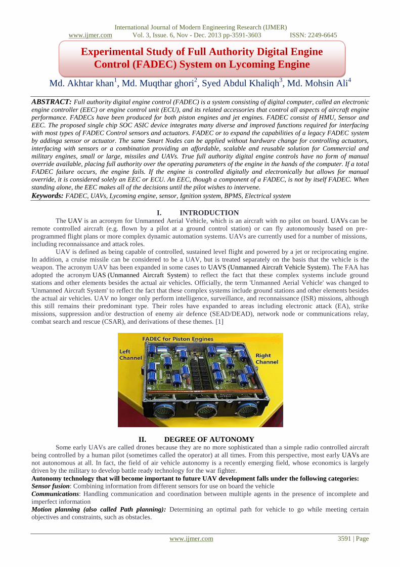
ABSTRACT: Full authority digital engine control (FADEC) is a system consisting of digital computer, called an electronic
engine controller (EEC) or engine control unit (ECU), and its related accessories that control all aspects of aircraft engine
performance. FADECs have been produced for both piston engines and jet engines. FADEC consist of HMU, Sensor and
EEC. The proposed single chip SOC ASIC device integrates many diverse and improved functions required for interfacing
with most types of FADEC Control sensors and actuators. FADEC or to expand the capabilities of a legacy FADEC system
by addinga sensor or actuator. The same Smart Nodes can be applied without hardware change for controlling actuators,
interfacing with sensors or a combination providing an affordable, scalable and reusable solution for Commercial and
military engines, small or large, missiles and UAVs. True full authority digital engine controls have no form of manual
override available, placing full authority over the operating parameters of the engine in the hands of the computer. If a total
FADEC failure occurs, the engine fails. If the engine is controlled digitally and electronically but allows for manual
override, it is considered solely an EEC or ECU. An EEC, though a component of a FADEC, is not by itself FADEC. When
standing alone, the EEC makes all of the decisions until the pilot wishes to intervene.
Keywords: FADEC, UAVs, Lycoming engine, sensor, Ignition system, BPMS, Electrical system
I. INTRODUCTION The UAV is an acronym for Unmanned Aerial Vehicle, which is an aircraft with no pilot on board. UAVs can be
remote controlled aircraft (e.g. flown by a pilot at a ground control station) or can fly autonomously based on pre-
programmed flight plans or more complex dynamic automation systems. UAVs are currently used for a number of missions,
including reconnaissance and attack roles.
UAV is defined as being capable of controlled, sustained level flight and powered by a jet or reciprocating engine.
In addition, a cruise missile can be considered to be a UAV, but is treated separately on the basis that the vehicle is the
weapon. The acronym UAV has been expanded in some cases to UAVS (Unmanned Aircraft Vehicle System). The FAA has
adopted the acronym UAS (Unmanned Aircraft System) to reflect the fact that these complex systems include ground
stations and other elements besides the actual air vehicles. Officially, the term 'Unmanned Aerial Vehicle' was changed to
'Unmanned Aircraft System' to reflect the fact that these complex systems include ground stations and other elements besides
the actual air vehicles. UAV no longer only perform intelligence, surveillance, and reconnaissance (ISR) missions, although
this still remains their predominant type. Their roles have expanded to areas including electronic attack (EA), strike
missions, suppression and/or destruction of enemy air defence (SEAD/DEAD), network node or communications relay,
combat search and rescue (CSAR), and derivations of these themes. [1]
II. DEGREE OF AUTONOMY Some early UAVs are called drones because they are no more sophisticated than a simple radio controlled aircraft
being controlled by a human pilot (sometimes called the operator) at all times. From this perspective, most early UAVs are
not autonomous at all. In fact, the field of air vehicle autonomy is a recently emerging field, whose economics is largely
driven by the military to develop battle ready technology for the war fighter.
Autonomy technology that will become important to future UAV development falls under the following categories:
Sensor fusion: Combining information from different sensors for use on board the vehicle
Communications: Handling communication and coordination between multiple agents in the presence of incomplete and
imperfect information
Motion planning (also called Path planning): Determining an optimal path for vehicle to go while meeting certain
objectives and constraints, such as obstacles.
Experimental Study of Full Authority Digital Engine
Control (FADEC) System on Lycoming Engine

International Journal of Modern Engineering Research (IJMER)
www.ijmer.com Vol. 3, Issue. 6, Nov - Dec. 2013 pp-3591-3603 ISSN: 2249-6645
www.ijmer.com 3592 | Page
Trajectory Generation: Determining an optimal control manoeuvre to take to follow a given path or to go from one location
to another.
Task Allocation and Scheduling: Determining the optimal distribution of tasks amongst a group of agents, with time and
equipment constraints.
Cooperative Tactics: Formulating an optimal sequence and spatial distribution of activities between agents in order to
maximize chance of success in any given mission scenario.
Fig. 1: Schiebel S-100 fitted with a Lightweight Multirole Missile
Fig. 2: Aeron Scout in flight
III. CURRENT DAY UAVS PREDATOR
It is a MALE armed surveillance UAV. It was first designated as RQ-1A in 1997. In May 1998, a more powerful
turbo charged engine and wing de-icing system was installed. In the February of 2001, it became the first UAV to be
weaponized destroying a ground target with live Hellfire missile during flight tests.
Description:
The airframe is a low wing monoplane with slender fuselage, high aspect ratio wing and inverted V- tail. It has an advanced
low speed aerodynamic configuration and computer designed low Reynolds number aerofoils which provide high
aerodynamic efficiency. Inverted V- tail is a unique feature providing propeller protection and keeping the tail control
surfaces clear of wing turbulence. Advanced graphite/ epoxy construction resulted in very sturdy airframe and light structure.
It has a tri-cycle landing gear.[5]
Guidance and control:
Predator missions are conducted from the GA-ASI mobile GCS. Predator system comprises of several air vehicles, their
payloads, one GCS, communications and support equipment, spare parts and support.
Powerplant:
The predator is equipped with one 78.3kw(105hp) Rotax 914 four cylinder four stroke turbo charged engine with two blade
variable pitch propeller.
Fig. 3: UAV Predator
International Journal of Modern Engineering Research (IJMER)
www.ijmer.com Vol. 3, Issue. 6, Nov - Dec. 2013 pp-3591-3603 ISSN: 2249-6645
www.ijmer.com 3593 | Page
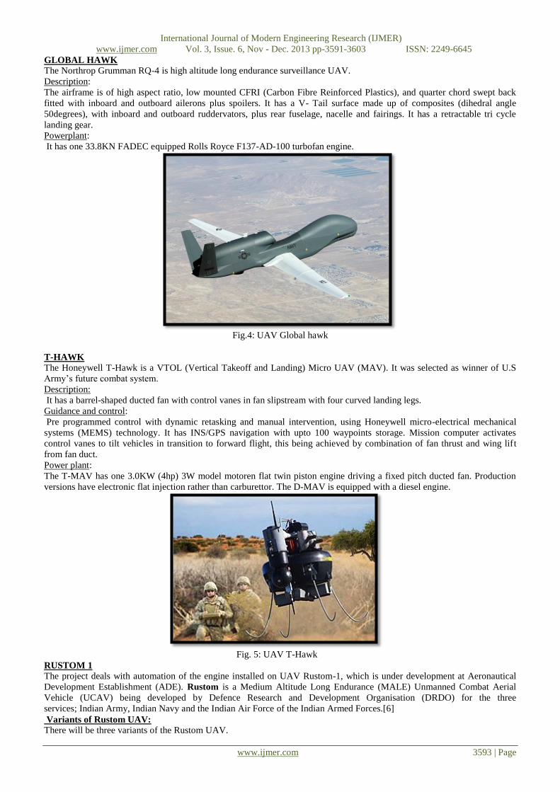
GLOBAL HAWK
The Northrop Grumman RQ-4 is high altitude long endurance surveillance UAV.
Description:
The airframe is of high aspect ratio, low mounted CFRI (Carbon Fibre Reinforced Plastics), and quarter chord swept back
fitted with inboard and outboard ailerons plus spoilers. It has a V- Tail surface made up of composites (dihedral angle
50degrees), with inboard and outboard ruddervators, plus rear fuselage, nacelle and fairings. It has a retractable tri cycle
landing gear.
Powerplant:
It has one 33.8KN FADEC equipped Rolls Royce F137-AD-100 turbofan engine.
Fig.4: UAV Global hawk
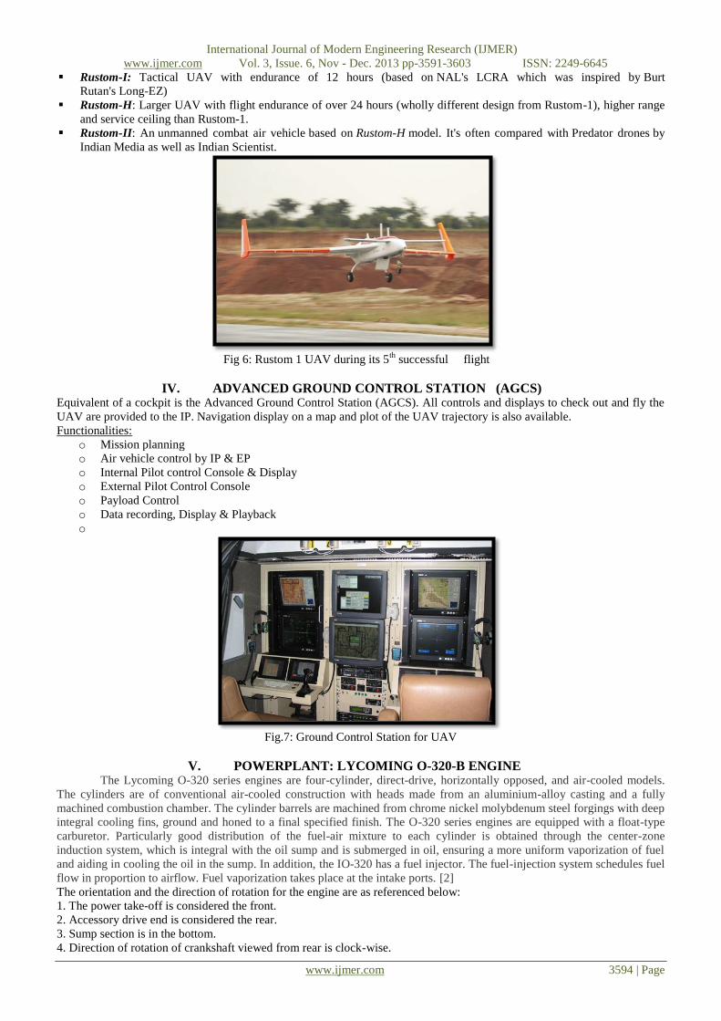
T-HAWK
The Honeywell T-Hawk is a VTOL (Vertical Takeoff and Landing) Micro UAV (MAV). It was selected as winner of U.S
Army’s future combat system.
Description:
It has a barrel-shaped ducted fan with control vanes in fan slipstream with four curved landing legs.
Guidance and control:
Pre programmed control with dynamic retasking and manual intervention, using Honeywell micro-electrical mechanical
systems (MEMS) technology. It has INS/GPS navigation with upto 100 waypoints storage. Mission computer activates
control vanes to tilt vehicles in transition to forward flight, this being achieved by combination of fan thrust and wing lift
from fan duct.
Power plant:
The T-MAV has one 3.0KW (4hp) 3W model motoren flat twin piston engine driving a fixed pitch ducted fan. Production
versions have electronic flat injection rather than carburettor. The D-MAV is equipped with a diesel engine.
Fig. 5: UAV T-Hawk
RUSTOM 1
The project deals with automation of the engine installed on UAV Rustom-1, which is under development at Aeronautical
Development Establishment (ADE). Rustom is a Medium Altitude Long Endurance (MALE) Unmanned Combat Aerial
Vehicle (UCAV) being developed by Defence Research and Development Organisation (DRDO) for the three
services; Indian Army, Indian Navy and the Indian Air Force of the Indian Armed Forces.[6]
Variants of Rustom UAV:
There will be three variants of the Rustom UAV.
International Journal of Modern Engineering Research (IJMER)
www.ijmer.com Vol. 3, Issue. 6, Nov - Dec. 2013 pp-3591-3603 ISSN: 2249-6645
www.ijmer.com 3594 | Page
Rustom-I: Tactical UAV with endurance of 12 hours (based on NAL's LCRA which was inspired by Burt
Rutan's Long-EZ)
Rustom-H: Larger UAV with flight endurance of over 24 hours (wholly different design from Rustom-1), higher range
and service ceiling than Rustom-1.
Rustom-II: An unmanned combat air vehicle based on Rustom-H model. It's often compared with Predator drones by
Indian Media as well as Indian Scientist.
Fig 6: Rustom 1 UAV during its 5
th successful flight
IV. ADVANCED GROUND CONTROL STATION (AGCS) Equivalent of a cockpit is the Advanced Ground Control Station (AGCS). All controls and displays to check out and fly the
UAV are provided to the IP. Navigation display on a map and plot of the UAV trajectory is also available.
Functionalities:
o Mission planning
o Air vehicle control by IP & EP
o Internal Pilot control Console & Display
o External Pilot Control Console
o Payload Control
o Data recording, Display & Playback
o
Fig.7: Ground Control Station for UAV
V. POWERPLANT: LYCOMING O-320-B ENGINE The Lycoming O-320 series engines are four-cylinder, direct-drive, horizontally opposed, and air-cooled models.
The cylinders are of conventional air-cooled construction with heads made from an aluminium-alloy casting and a fully
machined combustion chamber. The cylinder barrels are machined from chrome nickel molybdenum steel forgings with deep
integral cooling fins, ground and honed to a final specified finish. The O-320 series engines are equipped with a float-type
carburetor. Particularly good distribution of the fuel-air mixture to each cylinder is obtained through the center-zone
induction system, which is integral with the oil sump and is submerged in oil, ensuring a more uniform vaporization of fuel
and aiding in cooling the oil in the sump. In addition, the IO-320 has a fuel injector. The fuel-injection system schedules fuel
flow in proportion to airflow. Fuel vaporization takes place at the intake ports. [2]
The orientation and the direction of rotation for the engine are as referenced below:
1. The power take-off is considered the front.
2. Accessory drive end is considered the rear.
3. Sump section is in the bottom.
4. Direction of rotation of crankshaft viewed from rear is clock-wise.
International Journal of Modern Engineering Research (IJMER)
www.ijmer.com Vol. 3, Issue. 6, Nov - Dec. 2013 pp-3591-3603 ISSN: 2249-6645
www.ijmer.com 3595 | Page
5.1 PARTS OF ENGINE
The major parts of the Lycoming O-320-B engine are as listed below:[3]
Cylinders: The cylinders are convectional air-cooled construction with two major parts: head and barrel, screwed and
shrunk together made of aluminium alloy. The cylinder barrel has deep integral cooling fins.
Valve Operating Mechanism: A convectional type camshaft is located above and parallel to camshaft which actuates
hydraulic tappets which operate valves through push rods and valve rockers.
Crank-Case: Crank-case assembly consists of two reinforced Aluminium alloy castings, fastened together by means of
studs, bolts and nuts.
Crank-Shaft: It is made of chrome nickel-molybdenum steel forging.
Connecting-Rod: They are made in the form of H sections from alloy steel forgings. They have replaceable bearing inserts
in the crankshaft ends and bronze bushings in the piston ends.
Pistons: They are made of Aluminium alloy, and are full floating type with a plug located in each end of piston pin.
Depending on cylinder assembly, pistons may employ either half wedge or full wedge rings.
Accessory-Housing: It is fastened to rear of crank-case and top rear of the sump. It forms housing for oil pump and various
accessory drives.
Oil Sump: It incorporates oil drain plug, oil suction screen, mounting pad for carburetor, the intake riser and intake pipe
connections.
Fig. 8: Lycoming O-320-B Engine on Test Bed
VI. SYSTEMS OF ENGINE Cooling Systems: These engines are designed to be cooled by air pressure. Baffles are provided to build up a pressure and
force the air through cylinder fins.
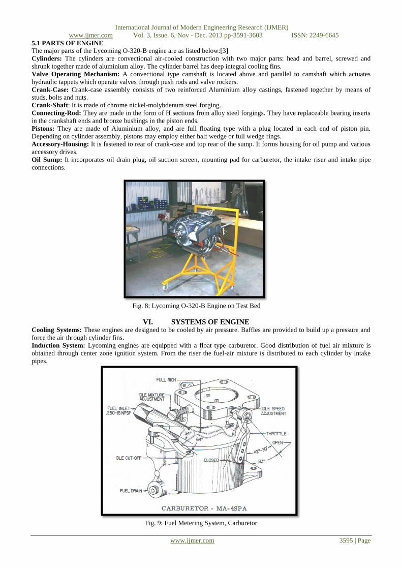
Induction System: Lycoming engines are equipped with a float type carburetor. Good distribution of fuel air mixture is
obtained through center zone ignition system. From the riser the fuel-air mixture is distributed to each cylinder by intake
pipes.
Fig. 9: Fuel Metering System, Carburetor

International Journal of Modern Engineering Research (IJMER)
www.ijmer.com Vol. 3, Issue. 6, Nov - Dec. 2013 pp-3591-3603 ISSN: 2249-6645
www.ijmer.com 3596 | Page
Lubrication Systems: It is pressure-wet sump type. The main bearings, connecting rod bearings, camshaft bearings, push-
rods and crankshaft idler gears are lubricated by means of oil collectors and spray.
Priming System: The provision for the primer system is provided for all engines.
Ignition System: Dual ignition is furnished by two magnetos. Bendix magnetos are designed to permit periodic internal
maintenance; slick electro magnetos are designed to operate for 900 hours without internal maintenance.
ENGINE SPECIFICATIONS
Rated Horsepower 160
Rated Speed (RPM) 2700
Bore (Inches) 5.125
Stroke (Inches) 3.875
Displacement (Cubic Inches) 319.8
Compressor Ratio 8.5:1
Firing Order 1-3-2-4
Spark occurs (Degrees BTC) 25
Valve Rocker Clearance 0.028-0.080
Propeller Drive Ratio 1:1
Propeller Drive Rotation Clockwise
VII. PERFORMANCE CURVE Performance data for correction of BHP from Altitude, RPM, Manifold Pressure & Air Inlet Temperature.
Fig.10 Graph for Sea Level & Altitude Performance for Lycoming O-320-B Engine
AUTOMATION OF ENGINE
The existing Internal Combustion engine is the Lycoming O-320-B which is four-cylinder air-cooled horizontally
opposed engine with fixed pitch propeller. It has certain drawbacks that have to be considered and solved for the better
performance and safety of the system.The two basic areas where the problem arises are the Fuel Injection system and the
Ignition system.
With the automation of engine, these problems are ciphered and the system is improved. The automation of engine deals
with the installation of an Electronic Controlling unit for handling the inputs and outputs of the system and control the
function of Ignition and Fuel Injection.
The automation is achieved with the installation of FADEC system. FADEC stands for Full Authority Digital Engine
Control. The ECU (Engine Control Unit - digital computer) controls all aspects of the engine performance and decides on
the amount of fuel it injects into the inlet ports as well as the exact timing of the spark advance.
This deals with the major drawbacks of the Internal Combustion engine and how the installation of FADEC system deals
with these problems. Following are the disadvantages of the I.C. engines that are dealt by FADEC system:
Ignition system: Magneto Ignition system replaced with Electronic Ignition system
Fuel Injection system: Carburetor replaced with Electronic Fuel Injection system
VIII. FADEC (FULL AUTHORITY DIGITAL ENGINE CONTROL) SYSTEM The FADEC (Full Authority Digital Engine Control) is a total system for the control of an engine. It controls all
aspects of aircraft engine performance. In simpler words, FADEC is a computer that controls the engine of the aircraft, just
like Fly-by-wire but in an engine’s aspect.
FADEC’s main purpose is to provide optimum engine efficiency for a given flight condition. FADEC controls the aircraft’s
engine and propeller in order to perform at a maximum efficiency. It does this by controlling the power of the reciprocating
engine and by adjusting the amount of fuel injection during the combustion process.
International Journal of Modern Engineering Research (IJMER)
www.ijmer.com Vol. 3, Issue. 6, Nov - Dec. 2013 pp-3591-3603 ISSN: 2249-6645
www.ijmer.com 3597 | Page
It controls and regulates the fuel pump, providing to the engine the necessary amount of fuel for safe and controlled
operation. The FADEC system also continuously monitors and controls ignition timing, fuel injection timing, and fuel-to-air
ratio mixture.
Certain input variables necessary for the flight such as air density, engine temperature and engine pressure are fed into the
system.
Since FADEC is more or less a computer that has no manual override, it operates with certain limits provided by the
manufacturer of each engine aircraft. During aircraft starting, the FADEC primes the cylinders, adjusts the fuel to air
mixture, and positions the throttle based on engine temperature and ambient pressure. During cruise flight, the FADEC
constantly monitors the engine and adjusts fuel flow, and ignition timing individually in each cylinder.[4]
The FADEC also allows the manufacturer to program engine limitations and receive engine health and maintenance reports.
For safety, FADEC is housed with a separate generator with two channels (A and B) to prevent a total failure. The two
channels are housed in one assembly but physically separated. If one channel fails completely, the other channel will take
over and it is unlikely that both channels would fail. Aircraft input power of 12V (or 24V) DC is necessary for back-up
power.
OPERATIONS The various operations of FADEC are:
Controls the ignition spark
Controls the air-fuel mixture of the engine
Engine acceleration to idle speed during start
Acceleration and deceleration limiting
Minimum approach idle speeds during descents
Selection of alternative power modes
Monitors cylinder head, manifold and exhaust gas temperatures and pressures.
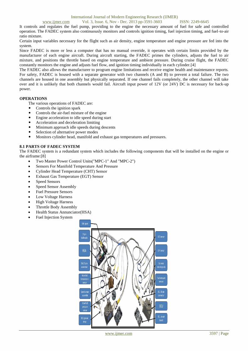
8.1 PARTS OF FADEC SYSTEM
The FADEC system is a redundant system which includes the following components that will be installed on the engine or
the airframe:[8]
Two Master Power Control Units("MPC-1" And "MPC-2")
Sensors For Manifold Temperature And Pressure
Cylinder Head Temperature (CHT) Sensor
Exhaust Gas Temperature (EGT) Sensor
Speed Sensors
Speed Sensor Assembly
Fuel Pressure Sensors
Low Voltage Harness
High Voltage Harness
Throttle Body Assembly
Health Status Annunciator(HSA)
Fuel Injection System

International Journal of Modern Engineering Research (IJMER)
www.ijmer.com Vol. 3, Issue. 6, Nov - Dec. 2013 pp-3591-3603 ISSN: 2249-6645
www.ijmer.com 3598 | Page
FADEC SYSTEM DESCRIPTION
Each MPC unit has a lower portion and an upper portion. The lower portion contains an electronic circuit board; the
upper portion houses the ignition coils. The Electronic circuit board contains two, independent microprocessor controllers
called "control channels".
Each control channel is assigned to a single engine cylinder. Since there are two control channels in each MPC, a
single MPC unit can operate two engine cylinders. (There are no shared electronic components between the two control
channels.)
For redundancy, each control channel is capable of operating its assigned cylinder and a cylinder assigned to the
second control channel within the same MPC unit.
Each control channel monitors the current operating conditions and manages its cylinder in a manner that will yield
maximum operating performance and efficiency within specified operating parameters. If operating conditions change, the
control channel adjusts both the fuel mixture and ignition timing to return the cylinder to normal operating parameters.
The control channels also receive input from the pilot via the throttle control thereby eliminating manual mixture control.
Primary/Secondary power is supplied by the Cabin Harness through the Bulkhead Connectors.
Information from the MPC units is conveyed to the HSA and the cockpit-mounted data port through the same Cabin
Harness/Bulkhead Connector Assembly.
The FADEC system continuously monitors fuel and ignition conditions. The MPC units receive information from
sensors via the Low Voltage Harness which interfaces with the MPC units via 50-pin connectors. The Low Voltage Harness
connects to the Cabin Harness via firewall-mounted Bulkhead Connectors.
The status of the FADEC system is conveyed to the pilot by the HSA. Discrete lamps in the HSA will illuminate
upon detection of system faults and during some normal control actions.
Sensor input to each control channel includes engine speed, crank position, fuel pressure, intake manifold air pressure, intake
manifold air temperature and Wide Open Throttle (WOT) position. In addition, each control channel also receives exclusive
signals for measuring its cylinder's head temperature and exhaust gas temperature.
The control channels in the MPC units use the signals from sensors to determine the required fuel mixture and
ignition timing for its cylinder's next combustion event. The required fuel quantity is injected into each cylinder intake port
at the appropriate time, with respect to crank position, by a solenoid style fuel injector. The injector's control coil is driven
directly by the associated control channel.
All critical sensors are redundant with one sensor from each pair connected to channels in different MPC units.
Synthetic software default values are also used if both sensors of a redundant pair should fail. This arrangement supports the
functional redundancy of the FADEC system. [6]
The FADEC system is electrically powered and not self-excited. As such, the system requires two, independent
power supply sources. Typically one source will be the aircraft's primary electrical bus, referred to as Primary Power. The
second source, referred to as Secondary Power, may be a second aircraft bus, an engine driven generating device, or a
battery. Electrical power to the FADEC system is controlled from the cockpit by two switches used to interrupt the Primary
Power and Secondary Power.
Using a conventional aircraft-style Ignition Switch, the pilot controls the enabling, starting, and disabling of the
FADEC system.The Fuel System must be pressurized at start-up to suppress vapour. The mechanical engine driven fuel
pump provides pressure for normal operation. For this reason, an Electric Boost Pump is required for starting. efficiency will
be reduced. BLOCK DIAG. OF FADEC SYSTEM
International Journal of Modern Engineering Research (IJMER)
www.ijmer.com Vol. 3, Issue. 6, Nov - Dec. 2013 pp-3591-3603 ISSN: 2249-6645
www.ijmer.com 3599 | Page
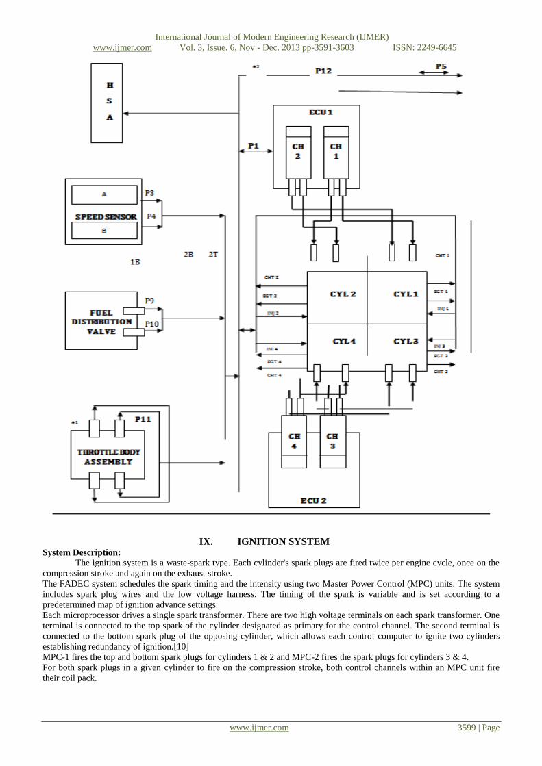
IX. IGNITION SYSTEM System Description:
The ignition system is a waste-spark type. Each cylinder's spark plugs are fired twice per engine cycle, once on the
compression stroke and again on the exhaust stroke.
The FADEC system schedules the spark timing and the intensity using two Master Power Control (MPC) units. The system
includes spark plug wires and the low voltage harness. The timing of the spark is variable and is set according to a
predetermined map of ignition advance settings.
Each microprocessor drives a single spark transformer. There are two high voltage terminals on each spark transformer. One
terminal is connected to the top spark of the cylinder designated as primary for the control channel. The second terminal is
connected to the bottom spark plug of the opposing cylinder, which allows each control computer to ignite two cylinders
establishing redundancy of ignition.[10]
MPC-1 fires the top and bottom spark plugs for cylinders 1 & 2 and MPC-2 fires the spark plugs for cylinders 3 & 4.
For both spark plugs in a given cylinder to fire on the compression stroke, both control channels within an MPC unit fire
their coil pack.

International Journal of Modern Engineering Research (IJMER)
www.ijmer.com Vol. 3, Issue. 6, Nov - Dec. 2013 pp-3591-3603 ISSN: 2249-6645
www.ijmer.com 3600 | Page
Fig.10: Ignition system
X. FUEL INJECTION SYSTEM System Description:
The FADEC system schedules the amount of fuel and the injection timing for the multi-port fuel injectors, thereby
eliminating the mixture control. The FADEC system compensates for changes in altitude by monitoring the intake manifold
pressure. [6]
The FADEC system controls the fuel supplied to each cylinder using solenoid-actuated sequential port Fuel injectors. The
Fuel Injection System is composed of:
An engine-driven Fuel Pump
Fuel Distribution Block and fuel lines
Solenoid-controlled Fuel Injection Nozzles
Each computer channel in the MPC unit obtains data from its own sensors and computes the amount of fuel to inject. The
electronic fuel injector injects fuel into the intake port upstream of the intake valve. The fuel injection timing is based on
engine speed and position. The flow is therefore intermittent, and not a continuous flow.
Fig11: FADEC Fuel Distribution System

International Journal of Modern Engineering Research (IJMER)
www.ijmer.com Vol. 3, Issue. 6, Nov - Dec. 2013 pp-3591-3603 ISSN: 2249-6645
www.ijmer.com 3601 | Page
ELECTRICAL SYSTEM
System Description
The engine electrical interfaces are the starter, the alternator, battery terminals, the FADEC system main power
supply and the FADEC system auxiliary power supply. The FADEC connections also supply operating data to the Health
Status Annunciator (HSA) panel and the optional Engine Performance Display (EPD). The FADEC system has a data port
for engine diagnostics using a compatible computer. [8]
The FADEC system requires two independent power sources. The primary source of FADEC electrical power is provided
from the aircraft power bus. The redundant source of FADEC electrical power can be provided from either of the below
three modes:
A dedicated backup battery
A dedicated alternator
An essential aircraft electrical bus
In the FADEC system being installed on the converted Lycoming engine, the auxiliary power is provided by a dedicated
backup battery. The circuit diagram for it is depicted here.[7]
Fig12: Dedicated Battery Electrical Supply for FADEC system Auxiliary Power
ELECTRICAL SYSTEM FADEC BLOCK DIAGRAM:
A block diagram depicting the basic connection of the Electrical system is as follows:[8]
International Journal of Modern Engineering Research (IJMER)
www.ijmer.com Vol. 3, Issue. 6, Nov - Dec. 2013 pp-3591-3603 ISSN: 2249-6645
www.ijmer.com 3602 | Page
XI. TESTING AND VALIDATION The Powerplant of Rustom-1: Lycoming O-320-B engine is integrated with the Full Authority Digital Engine Control
(FADEC) system following the procedure explained in the previous chapter. This chapter deals with the testing and
validation of the FADEC integrated Lycoming Engine. The procedure and test run data are included here.
APPARATUS USED:
FADEC Integrated Lycoming Engine
Engine Test Bed
Alternator/ Starter Motor
Fuel Sump
Oil Sump
Control Panel
Engine Performance Monitor: VM-1000 software
PROCEDURE:
ENGINE STARTING
1. The FADEC System is energized by Switching ON the FADEC Master Switch.
2. Primary Power Switch is switched ON.
3. Secondary Power Switch is switched ON.
4. Throttle Position Switch is opened to 1/4- inch.
5. Boost Pump Mode Switch (BPMS) is switched to either ON or AUTO.
6. Engine Starter is engaged.
7. Engine is primed with initial charge of fuel.
8. Camshaft signal is monitored for the timing pulse.
9. Position of Crankshaft is ascertained.
10. First Spark is commanded.
11. Camshaft timing pulse is received from the timing sensor.
12. Commencement of Fuel Injection and Ignition Control by FADEC system.
13. The engine Starts.
14. Starter is disengaged.
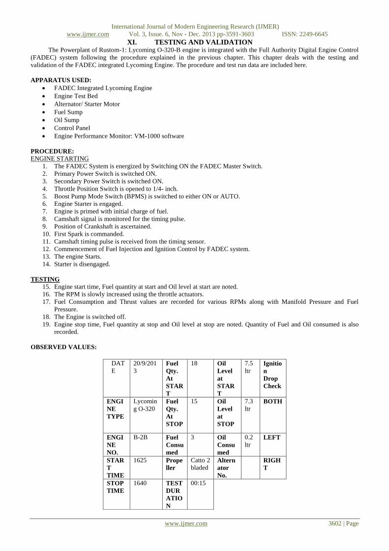
TESTING
15. Engine start time, Fuel quantity at start and Oil level at start are noted.
16. The RPM is slowly increased using the throttle actuators.
17. Fuel Consumption and Thrust values are recorded for various RPMs along with Manifold Pressure and Fuel
Pressure.
18. The Engine is switched off.
19. Engine stop time, Fuel quantity at stop and Oil level at stop are noted. Quantity of Fuel and Oil consumed is also
recorded.
OBSERVED VALUES:
DAT
E
20/9/201
3 Fuel
Qty.
At
STAR
T
18 Oil
Level
at
STAR
T
7.5
ltr Ignitio
n
Drop
Check
ENGI
NE
TYPE
Lycomin
g O-320 Fuel
Qty.
At
STOP
15 Oil
Level
at
STOP
7.3
ltr BOTH
ENGI
NE
NO.
B-2B Fuel
Consu
med
3 Oil
Consu
med
0.2
ltr LEFT
STAR
T
TIME
1625 Prope
ller
Catto 2
bladed Altern
ator
No.
RIGH
T
STOP
TIME
1640 TEST
DUR
ATIO
N
00:15

International Journal of Modern Engineering Research (IJMER)
www.ijmer.com Vol. 3, Issue. 6, Nov - Dec. 2013 pp-3591-3603 ISSN: 2249-6645
www.ijmer.com 3603 | Page
Following tables gives the readings for Engine run test data:
XII. CONCLUSION The FADEC Integrated Lycoming Engine is run successfully at various RPMs and the values of Fuel Consumption
and Thrust are recorded. The fuel efficiency is increased and performance of engine is improved too. The study of
“Integration of FADEC system on Lycoming Engine” on Unmanned Aerial Vehicles (UAV) is carried out. Its working,
classification and applications are discussed along with current day UAVs. Rustom-1 is a Medium Altitude Long Endurance
(MALE) UAV being developed by DRDO for the Indian Armed Forces. The basics of Internal Combustion engine are
discussed. The Powerplant of Rustom-1 is the subject of study in the project. Lycoming O-320-B is a 160 BHP @2700 RPM
four cylinder, horizontally opposed, air cooled engine with fixed pitch propeller. The efficiency and performance of the
engine is studied. The need for the automation of engine is mentioned by listing the shortcomings of conventional systems
and the advantages of Electronic Fuel injection and ignition systems. An extensive study of Full Authority Digital Engine
Control (FADEC) system is carried out. Its major parts, system description and working are studied.
FUTURE SCOPE
Full Authority Digital Engine Control (FADEC) system finds practical application in various domains like Aviation
Industry and Automobile Industry. The automation of engine has multitudinous advantages over conventional systems of
engine. By projecting the supremacy of the FADEC system, the need for conversion of conventional engines is emphasized.
But the system is not completely void of any drawbacks. It doesn’t provide any manual override since it takes over the
engine completely. In case of emergency, the system becomes highly unreliable. Also due to the complexity of the system, a
lot of efforts have to put for its development and validation.
It deals with the integration of FADEC system in Lycoming O-320-B engine. It improves the engine performance and fuel
efficiency. The integrated engine is tested for various throttle settings. The fuel consumption and thrust are recorded for
different engine RPMs.
The test should be carried out for various altitudes too so that the actual engine BHP can be recorded as opposed to
theoretical values.
REFERENCES [1] Gunston (1990) Avionics: The story and technology of aviation electronics Patrick Stephens Ltd, Wellingborough UK. 254pp,
ISBN 1-85260-133-7
[2] Moren, Chuck. Interview with student. FADEC. Embry-Riddle Aeronautical University, Daytona Beach. 2007-03-13.
[3] Title 14 CFR: Federal Aviation Regulations. FAA. 2007-03-10.
[4] Jane’s Journals: Jane's UAV and Targets (Issues 30-37).
[5] Aircraft Powerplants, 4th edition by Ralph D. Bent & James L. McKinley
[6] Fundamentals of I.C engines by Paul W. Gill & James H. Smith
[7] Manual: Lycoming O-320-B engine by Teledyne Motors
[8] Manual: Integration of Full Authority Digital Engine Control (FADEC) System in Textron Lycoming O-360 engine .
[9] "Safran Electronics Canada: FADEC and EEC". Retrieved 2010-04-30.
[10] "Hispano-Suiza: Digital Engine Control". Retrieved 2007-03-09.
Sl.
No.
RPM
(N)
MANIF
OLD
PR.
(inch of
Hg) Pm
FUE
L PR.
(psi)
Pf
FUEL
CONSUMP
TION
(Lt/Hr) Vf
THRUST
(kgF) F
1. 730 11 6 1.4 13
2. 1200 14.7 6 4.2 45
3. 1500 17.4 6 6.6 65
4. 1700 20 5 9 85
5. 1900 22 5 10.8 100
6. 1950 23.1 5 12.8 107
7. 2000 23.4 5 13.2 116
8. 2100 24.5 5 14 120
9. 2200 25.1 5 15 130
10. 2285 25.9 5 15.8 138