CF34-10E FADEC System Fault Stragety and Troubleshooting.pdf
152
CF34-10E FADEC System Fault Strategy & Troubleshooting GEAE Proprietary Information Use or disclosure of the data on this page or image is subject to the restrictions noted on the first or title page Rev 4 Nov-06 CF34-10E CF34-10E FADEC SYSTEM ENGINE FAULT STRATEGY & TROUBLESHOOTING FADEC SYSTEM ENGINE FAULT STRATEGY & TROUBLESHOOTING
Transcript of CF34-10E FADEC System Fault Stragety and Troubleshooting.pdf
CF34-10E FADEC System Fault Strategy & TroubleshootingGEAE Proprietary Information
Use or disclosure of the data on this page or image is subject to the restrictions noted on the first or title pageRev 4 Nov-06
CF34-10ECF34-10E
FADEC SYSTEM ENGINE FAULTSTRATEGY & TROUBLESHOOTING
FADEC SYSTEM ENGINE FAULTSTRATEGY & TROUBLESHOOTING
CF34-10E FADEC System Fault Strategy & TroubleshootingGEAE Proprietary Information
Use or disclosure of the data on this page or image is subject to the restrictions noted on the first or title page
1Rev 4 Nov-06
!!! NOTICE !!!
This document is intended for TRAINING purposes only and does not replace the pertinent manufacturer's Maintenance
Manual.
The information was accurate at time of the compilation, however, the data will not be updated to maintain accuracy.
EMBRAER PROPRIETARY INFORMATIONThe information contained herein includes trade secrets of Embraer and is privileged and confidential. This information may not be copied or usedin any way whatsoever except as expressly authorized in writing by Embraer.GE PROPRIETARY INFORMATIONThe information (including technical data) contained in this document is the property of GE. It is disclosed in confidence and the technical datatherein is exported in accordance with the Export Administration Regulations under a U.S. Government authorization, TSU. Therefore, none of theinformation may be disclosed to other than the recipient, or used for purposes other than to render services to GE, without the express prior writtenauthorization of GE. In addition, the technical data therein, and the direct product of the data, may not be diverted, transferred, re-exported ordisclosed in any manner not provided for by the license without the prior written approval of the U.S. Government.These technologies or software were exported from the United States to Brazil in accordance with the Export Administration Regulations. Diversioncontrary to U.S. law is prohibited.
CF34-10E FADEC System Fault Strategy & TroubleshootingGEAE Proprietary Information
Rev 4 Nov-06
Slide Intentionally Left Blank
CF34-10E FADEC System Fault Strategy & TroubleshootingGEAE Proprietary Information
Use or disclosure of the data on this page or image is subject to the restrictions noted on the first or title page
3Rev 4 Nov-06
Control System Overview
CF34-10E FADEC System Fault Strategy & TroubleshootingGEAE Proprietary Information
Use or disclosure of the data on this page or image is subject to the restrictions noted on the first or title page
4Rev 4 Nov-06
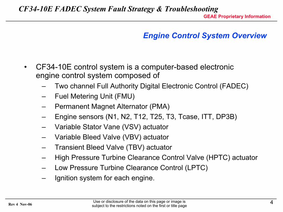
Engine Control System Overview
• CF34-10E control system is a computer-based electronic engine control system composed of
– Two channel Full Authority Digital Electronic Control (FADEC)– Fuel Metering Unit (FMU)– Permanent Magnet Alternator (PMA)– Engine sensors (N1, N2, T12, T25, T3, Tcase, ITT, DP3B)– Variable Stator Vane (VSV) actuator– Variable Bleed Valve (VBV) actuator– Transient Bleed Valve (TBV) actuator– High Pressure Turbine Clearance Control Valve (HPTC) actuator– Low Pressure Turbine Clearance Control (LPTC)– Ignition system for each engine.
CF34-10E FADEC System Fault Strategy & TroubleshootingGEAE Proprietary Information
Use or disclosure of the data on this page or image is subject to the restrictions noted on the first or title page
5Rev 4 Nov-06
AIR
CR
AFT
INT
ER
FAC
E
CH AFADEC
CH BFADEC
ECP
ECP
Engine Temperature Sensors
T12, T25, T3, Tcase, ITT
Engine Speed Sensors
N1,N2 Alternator, N2 Pump
Engine ActuatorsVSV, VBV
HPTACC, TBV
Alte
rnat
orN1,N2
to EVM
FMU
Fuel Filter DP Switch
GEAR BOX
ThrustReverser
Exciter
Exciter
P0
P3
P0
P3
Power
Power
Feedbacks
Feedbacks
Servo Flow
Oil Pressure, Oil Pressure Switch, Oil Filter DP Switch, Oil Chi p Detector, Oil Level
Overspeed Shutoff SolenoidFuel Flow Demand and Feedback
Actuator Position Demands
Overspeed Shutoff SolenoidFuel Flow Demand and Feedback
Actuator Position Demands
CH
ID
XC
APA
BLE
XTA
LK28 VDC
TLA VDT
Discretes
Relay Drivers
28 VDC
TLA VDT
Discretes
Relay Drivers
ARINC 429DATA BUS
ARINC 429DATA BUS
Test Connector
115V 400Hz
115V 400Hz
LVDT, Discrete
LVDT, Discrete
Control System Overview
CF34-10E FADEC System Fault Strategy & TroubleshootingGEAE Proprietary Information
Use or disclosure of the data on this page or image is subject to the restrictions noted on the first or title page
6Rev 4 Nov-06
CF34-10 Fuel System Schematic
IntegratedDriveGenerator(40 KVA)
Aft Sump
Fuel Metering Unit
Fuel Metering
Valve
By-Pass Valve
HPSOV
HPTCCEHSV
VSVEHSV
VBVEHSV
TBVEHSV
Fwd Sump
Fan Air
Motive Returnflow
Inletflow
VSV Actuators
VBV Actuators
TBV
HPTCC Valve
CORE
To
Man
ifold
s
BoostElement
Main Element
MotiveElement
IPV
FMVEHSV
OverspeedFunction
IDG A/O HEX
EBU
Servo F/O HexMain F/O Hex
Main Fuel Pump
Upper
Low
er
Wash Filter
Filter dPIndicator
Main Fuel Filter
IDG F/O Hex
By-pass
Fuel System Overview
CF34-10E FADEC System Fault Strategy & TroubleshootingGEAE Proprietary Information
Use or disclosure of the data on this page or image is subject to the restrictions noted on the first or title page
7Rev 4 Nov-06
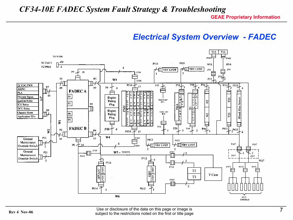
Electrical System Overview - FADEC
LPT
TM
LPT
TM
CF34-10E FADEC System Fault Strategy & TroubleshootingGEAE Proprietary Information
Use or disclosure of the data on this page or image is subject to the restrictions noted on the first or title page
8Rev 4 Nov-06
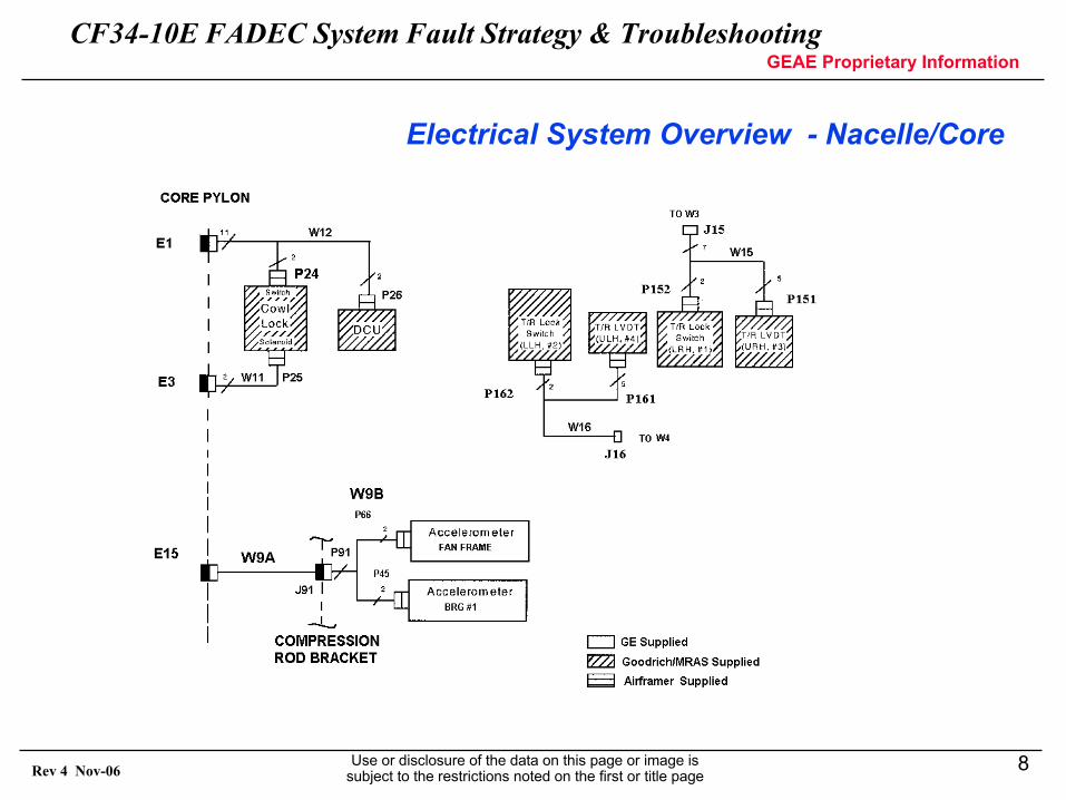
Electrical System Overview - Nacelle/Core
CF34-10E FADEC System Fault Strategy & TroubleshootingGEAE Proprietary Information
Use or disclosure of the data on this page or image is subject to the restrictions noted on the first or title page
9Rev 4 Nov-06
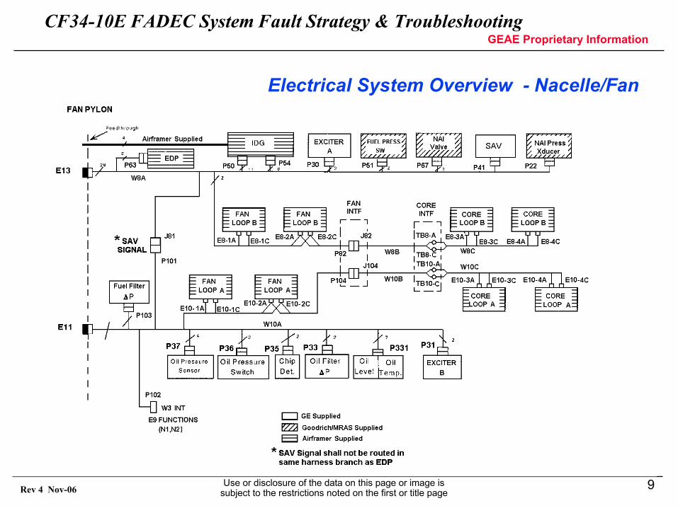
Electrical System Overview - Nacelle/Fan
CF34-10E FADEC System Fault Strategy & TroubleshootingGEAE Proprietary Information
Use or disclosure of the data on this page or image is subject to the restrictions noted on the first or title page
10Rev 4 Nov-06
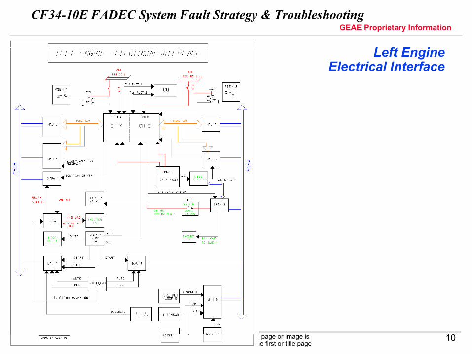
Left EngineElectrical Interface
CF34-10E FADEC System Fault Strategy & TroubleshootingGEAE Proprietary Information
Use or disclosure of the data on this page or image is subject to the restrictions noted on the first or title page
11Rev 4 Nov-06
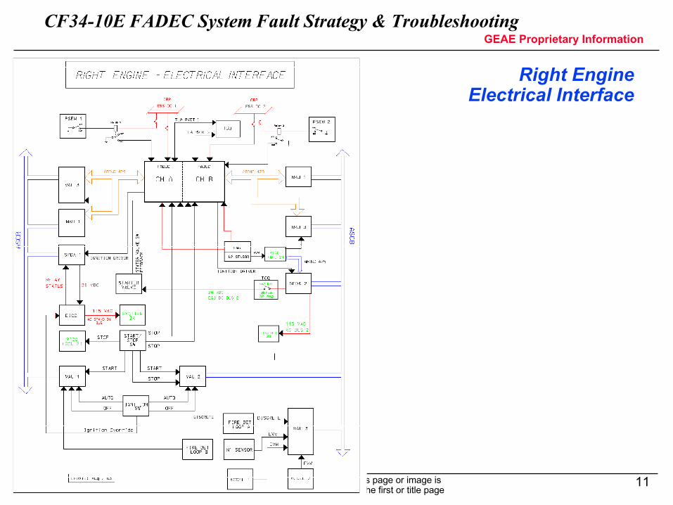
Right EngineElectrical Interface
CF34-10E FADEC System Fault Strategy & TroubleshootingGEAE Proprietary Information
Use or disclosure of the data on this page or image is subject to the restrictions noted on the first or title page
12Rev 4 Nov-06
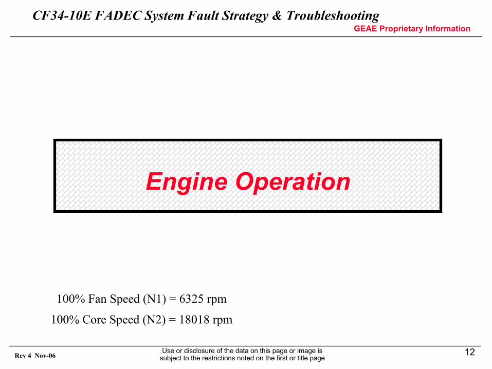
Engine Operation
100% Fan Speed (N1) = 6325 rpm
100% Core Speed (N2) = 18018 rpm
CF34-10E FADEC System Fault Strategy & TroubleshootingGEAE Proprietary Information
Use or disclosure of the data on this page or image is subject to the restrictions noted on the first or title page
13Rev 4 Nov-06
FADEC Control
• Engine is controlled by a dual channel FADEC– One channel is “in-control”– Other channel is “standby”– During normal operation and equally health channels, the channels
alternate control each start– Both channels share information across a CCDL (cross channel data
link) serial bus to maintain the maximum system fault tolerance– Channel in control is determined at 7% core speed
• FADEC is powered by aircraft 28 VDC bus until 50% core speed when the engine alternator (PMA) powers the FADEC
– 28 VDC power is also a backup power source in case the alternator fails• During the start sequence, the FADEC automatically controls fuel,
ignition, and starter cut out– Ignition turned on at 7% core speed – Fuel turned on at 20% core speed– Starter cut out occurs at 53% core speed
CF34-10E FADEC System Fault Strategy & TroubleshootingGEAE Proprietary Information
Use or disclosure of the data on this page or image is subject to the restrictions noted on the first or title page
14Rev 4 Nov-06
FADEC Control
• FADEC provides thrust management control– Throttle Lever Angle (TLA) is the main thrust setting input– Other inputs include Air Data System (ADS), engine sensors and aircraft
sensors– Inputs are used calculate reference corrected and physical fan speed
(N1) and core speed (N2) for a given TLA position– The thrust setting references may be modified by discrete inputs –
Automatic Takeoff Thrust Control System (ATTCS), Thrust Reverser, Weight on Wheels, and Modular Avionics Unit (MAU) discretes
CF34-10E FADEC System Fault Strategy & TroubleshootingGEAE Proprietary Information
Use or disclosure of the data on this page or image is subject to the restrictions noted on the first or title page
15Rev 4 Nov-06
FADEC Control
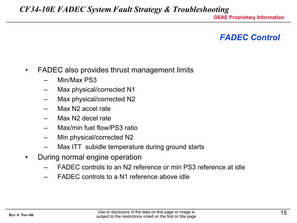
• FADEC also provides thrust management limits– Min/Max PS3– Max physical/corrected N1– Max physical/corrected N2– Max N2 accel rate– Max N2 decel rate– Max/min fuel flow/PS3 ratio– Min physical/corrected N2 – Max ITT subidle temperature during ground starts
• During normal engine operation– FADEC controls to an N2 reference or min PS3 reference at idle– FADEC controls to a N1 reference above idle
CF34-10E FADEC System Fault Strategy & TroubleshootingGEAE Proprietary Information
Use or disclosure of the data on this page or image is subject to the restrictions noted on the first or title page
16Rev 4 Nov-06
FADEC
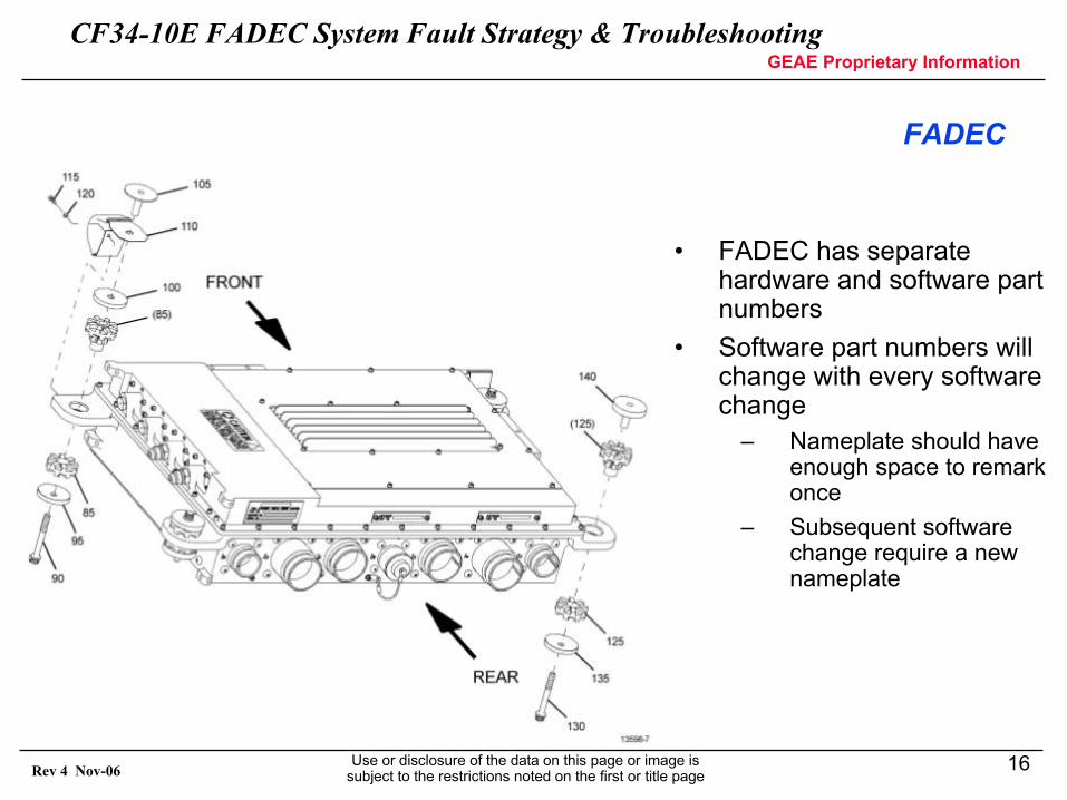
• FADEC has separate hardware and software part numbers
• Software part numbers will change with every software change
– Nameplate should have enough space to remark once
– Subsequent software change require a new nameplate
CF34-10E FADEC System Fault Strategy & TroubleshootingGEAE Proprietary Information
Use or disclosure of the data on this page or image is subject to the restrictions noted on the first or title page
17Rev 4 Nov-06
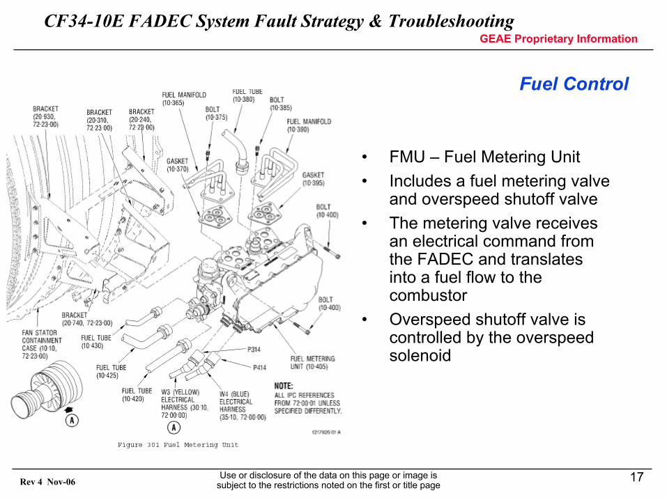
Fuel Control
• FMU – Fuel Metering Unit• Includes a fuel metering valve
and overspeed shutoff valve• The metering valve receives
an electrical command from the FADEC and translates into a fuel flow to the combustor
• Overspeed shutoff valve is controlled by the overspeed solenoid
CF34-10E FADEC System Fault Strategy & TroubleshootingGEAE Proprietary Information
Use or disclosure of the data on this page or image is subject to the restrictions noted on the first or title page
18Rev 4 Nov-06
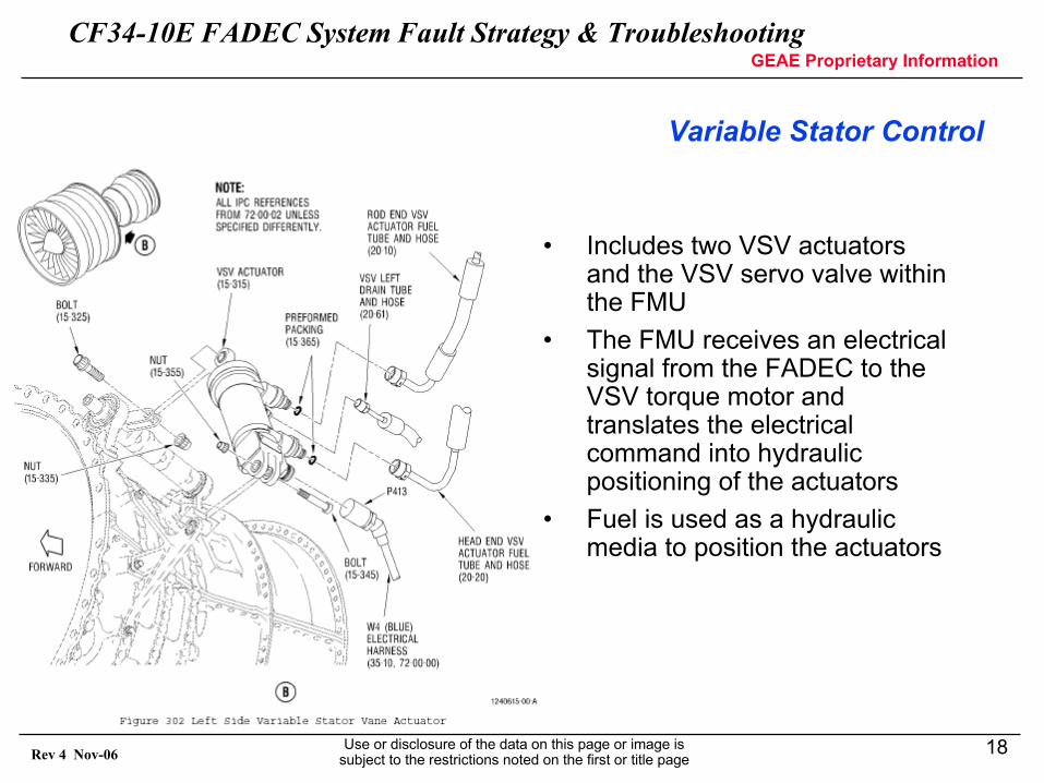
Variable Stator Control
• Includes two VSV actuators and the VSV servo valve within the FMU
• The FMU receives an electrical signal from the FADEC to the VSV torque motor and translates the electrical command into hydraulic positioning of the actuators
• Fuel is used as a hydraulic media to position the actuators
CF34-10E FADEC System Fault Strategy & TroubleshootingGEAE Proprietary Information
Use or disclosure of the data on this page or image is subject to the restrictions noted on the first or title page
19Rev 4 Nov-06
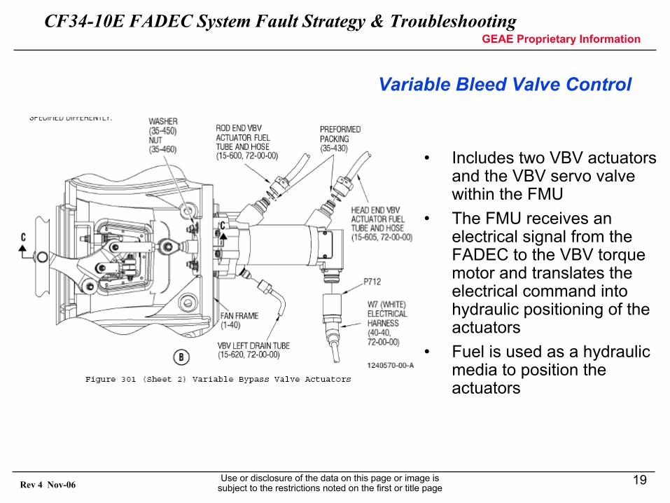
Variable Bleed Valve Control
• Includes two VBV actuators and the VBV servo valve within the FMU
• The FMU receives an electrical signal from the FADEC to the VBV torque motor and translates the electrical command into hydraulic positioning of the actuators
• Fuel is used as a hydraulic media to position the actuators
CF34-10E FADEC System Fault Strategy & TroubleshootingGEAE Proprietary Information
Use or disclosure of the data on this page or image is subject to the restrictions noted on the first or title page
20Rev 4 Nov-06
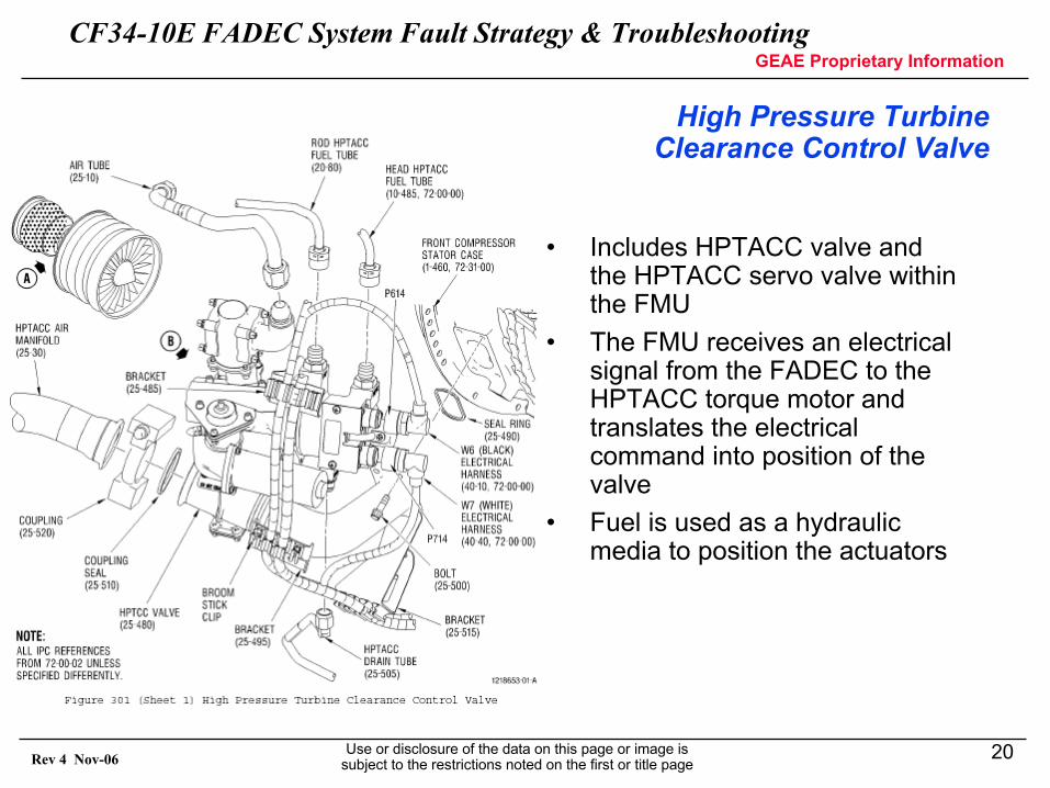
High Pressure Turbine Clearance Control Valve
• Includes HPTACC valve and the HPTACC servo valve within the FMU
• The FMU receives an electrical signal from the FADEC to the HPTACC torque motor and translates the electrical command into position of the valve
• Fuel is used as a hydraulic media to position the actuators
CF34-10E FADEC System Fault Strategy & TroubleshootingGEAE Proprietary Information
Use or disclosure of the data on this page or image is subject to the restrictions noted on the first or title page
21Rev 4 Nov-06
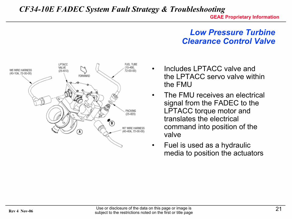
Low Pressure Turbine Clearance Control Valve
• Includes LPTACC valve and the LPTACC servo valve within the FMU
• The FMU receives an electrical signal from the FADEC to the LPTACC torque motor and translates the electrical command into position of the valve
• Fuel is used as a hydraulic media to position the actuators
CF34-10E FADEC System Fault Strategy & TroubleshootingGEAE Proprietary Information
Use or disclosure of the data on this page or image is subject to the restrictions noted on the first or title page
22Rev 4 Nov-06
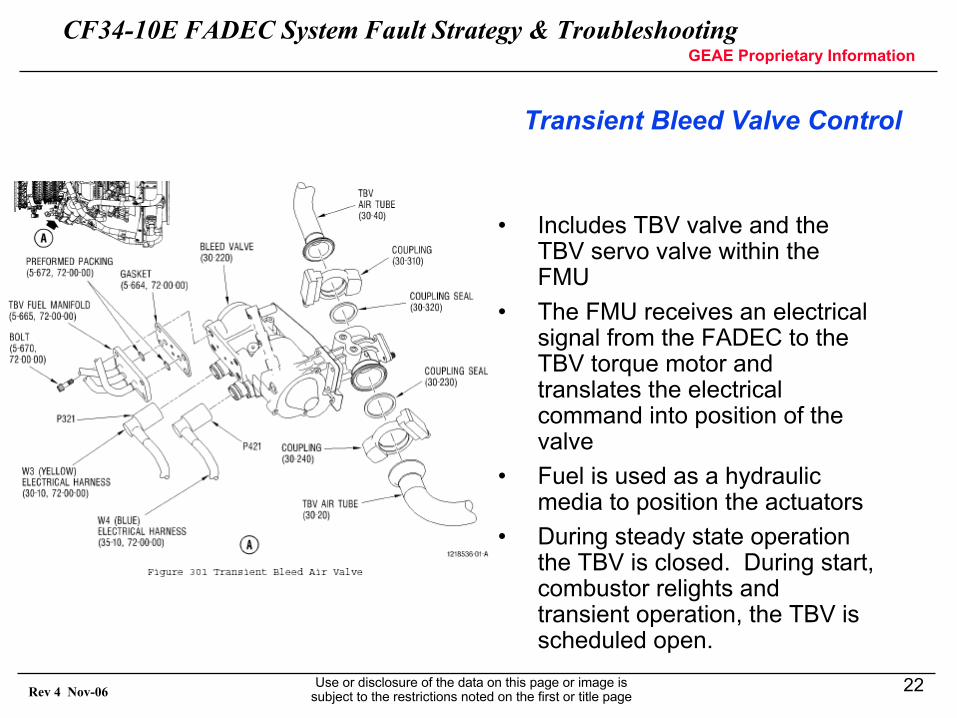
Transient Bleed Valve Control
• Includes TBV valve and the TBV servo valve within the FMU
• The FMU receives an electrical signal from the FADEC to the TBV torque motor and translates the electrical command into position of the valve
• Fuel is used as a hydraulic media to position the actuators
• During steady state operation the TBV is closed. During start, combustor relights and transient operation, the TBV is scheduled open.
CF34-10E FADEC System Fault Strategy & TroubleshootingGEAE Proprietary Information
Use or disclosure of the data on this page or image is subject to the restrictions noted on the first or title page
23Rev 4 Nov-06
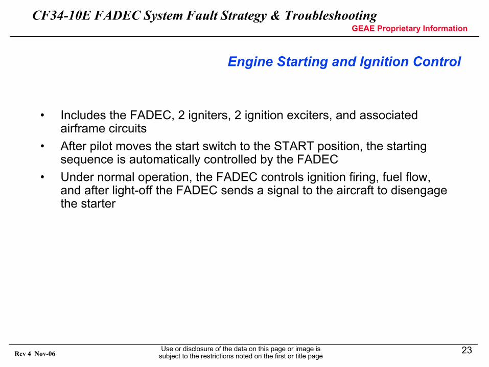
Engine Starting and Ignition Control
• Includes the FADEC, 2 igniters, 2 ignition exciters, and associated airframe circuits
• After pilot moves the start switch to the START position, the starting sequence is automatically controlled by the FADEC
• Under normal operation, the FADEC controls ignition firing, fuel flow, and after light-off the FADEC sends a signal to the aircraft to disengage the starter
CF34-10E FADEC System Fault Strategy & TroubleshootingGEAE Proprietary Information
Use or disclosure of the data on this page or image is subject to the restrictions noted on the first or title page
24Rev 4 Nov-06
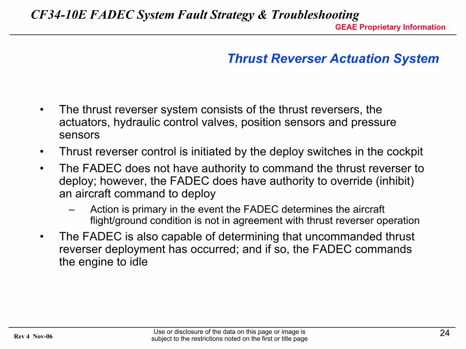
Thrust Reverser Actuation System
• The thrust reverser system consists of the thrust reversers, theactuators, hydraulic control valves, position sensors and pressure sensors
• Thrust reverser control is initiated by the deploy switches in the cockpit• The FADEC does not have authority to command the thrust reverser to
deploy; however, the FADEC does have authority to override (inhibit) an aircraft command to deploy
– Action is primary in the event the FADEC determines the aircraftflight/ground condition is not in agreement with thrust reverser operation
• The FADEC is also capable of determining that uncommanded thrustreverser deployment has occurred; and if so, the FADEC commands the engine to idle
CF34-10E FADEC System Fault Strategy & TroubleshootingGEAE Proprietary Information
Use or disclosure of the data on this page or image is subject to the restrictions noted on the first or title page
25Rev 4 Nov-06
FADEC SYSTEM FAULT STRATEGY
CF34-10E FADEC System Fault Strategy & TroubleshootingGEAE Proprietary Information
Use or disclosure of the data on this page or image is subject to the restrictions noted on the first or title page
26Rev 4 Nov-06
FAULT MANAGEMENT
• Fault System Overview• Fault Accommodation / Selection• Fault Detection• Fault Annunciation• Fault Annunciation/Dispatch Criteria
CF34-10E FADEC System Fault Strategy & TroubleshootingGEAE Proprietary Information
Use or disclosure of the data on this page or image is subject to the restrictions noted on the first or title page
27Rev 4 Nov-06
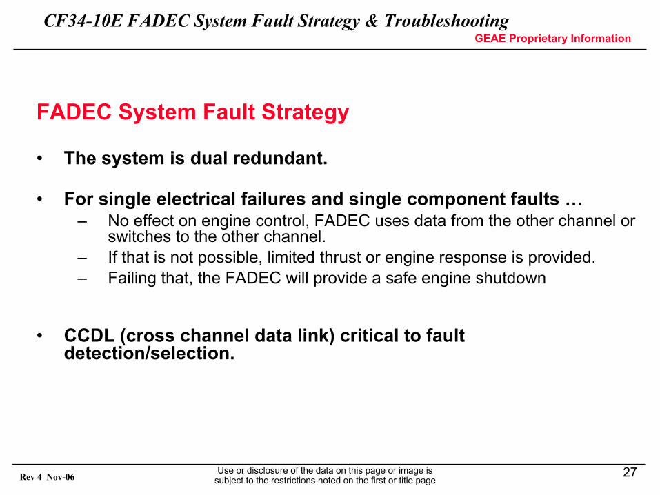
FADEC System Fault Strategy
• The system is dual redundant.
• For single electrical failures and single component faults …– No effect on engine control, FADEC uses data from the other channel or
switches to the other channel.– If that is not possible, limited thrust or engine response is provided.– Failing that, the FADEC will provide a safe engine shutdown
• CCDL (cross channel data link) critical to fault detection/selection.
CF34-10E FADEC System Fault Strategy & TroubleshootingGEAE Proprietary Information
Use or disclosure of the data on this page or image is subject to the restrictions noted on the first or title page
28Rev 4 Nov-06
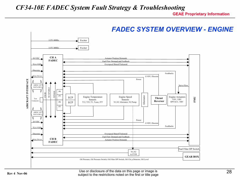
AIR
CR
AFT
INT
ER
FAC
E
CH AFADEC
CH BFADEC
ECP
ECP
Engine Temperature Sensors
T12, T25, T3, Tcase, ITT
Engine Speed Sensors
N1,N2 Alternator, N2 Pump
Engine ActuatorsVSV, VBV
HPTACC, TBV
Alte
rnat
or
N1,N2 to EVM
FMU
Fuel Filter DP Switch
GEAR BOX
ThrustReverser
Exciter
Exciter
P0
P3
P0
P3
Power
Power
Feedbacks
Feedbacks
Servo Flow
Oil Pressure, Oil Pressure Switch, Oil Filter DP Switch, Oil Chi p Detector, Oil Level
Overspeed Shutoff SolenoidFuel Flow Demand and Feedback
Actuator Position Demands
Overspeed Shutoff SolenoidFuel Flow Demand and Feedback
Actuator Position Demands
CH
ID
XC
APA
BLE
XTA
LK
28 VDC
TLA VDT
Discretes
Relay Drivers
28 VDC
TLA VDT
Discretes
Relay Drivers
ARINC 429DATA BUS
ARINC 429DATA BUS
Test Connector
115V 400Hz
115V 400Hz
LVDT, Discrete
LVDT, Discrete
FADEC SYSTEM OVERVIEW - ENGINE
CF34-10E FADEC System Fault Strategy & TroubleshootingGEAE Proprietary Information
Use or disclosure of the data on this page or image is subject to the restrictions noted on the first or title page
29Rev 4 Nov-06
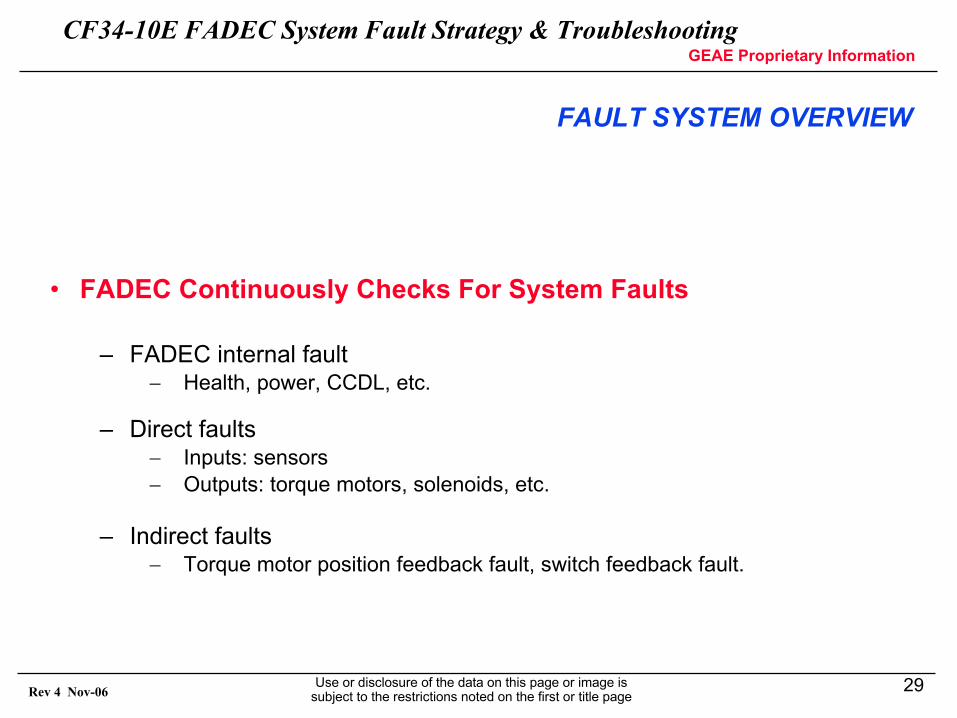
• FADEC Continuously Checks For System Faults
– FADEC internal fault − Health, power, CCDL, etc.
– Direct faults− Inputs: sensors− Outputs: torque motors, solenoids, etc.
– Indirect faults− Torque motor position feedback fault, switch feedback fault.
FAULT SYSTEM OVERVIEW
CF34-10E FADEC System Fault Strategy & TroubleshootingGEAE Proprietary Information
Use or disclosure of the data on this page or image is subject to the restrictions noted on the first or title page
30Rev 4 Nov-06
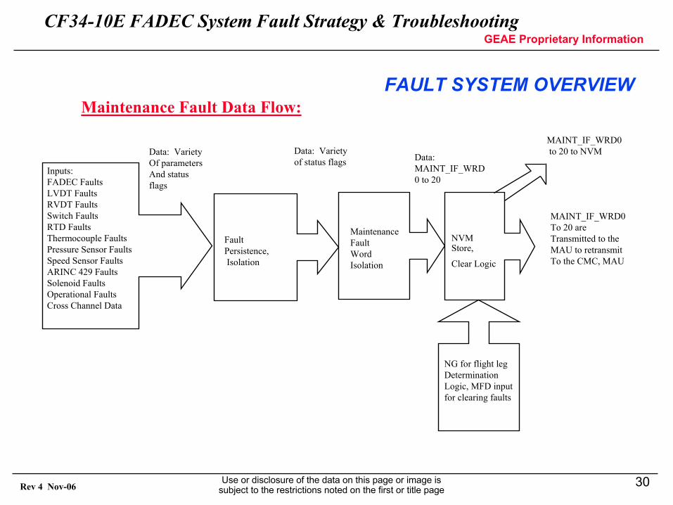
FAULT SYSTEM OVERVIEW
MAINT_IF_WRD0to 20 to NVM
MAINT_IF_WRD0To 20 areTransmitted to theMAU to retransmitTo the CMC, MAU
Inputs:FADEC FaultsLVDT FaultsRVDT FaultsSwitch FaultsRTD FaultsThermocouple FaultsPressure Sensor FaultsSpeed Sensor FaultsARINC 429 FaultsSolenoid FaultsOperational FaultsCross Channel Data
Fault Persistence,Isolation
NVM Store,
Clear Logic
Maintenance Fault Word Isolation
Data: VarietyOf parametersAnd statusflags
Data: Varietyof status flags Data:
MAINT_IF_WRD0 to 20
NG for flight legDeterminationLogic, MFD input for clearing faults
Maintenance Fault Data Flow:
CF34-10E FADEC System Fault Strategy & TroubleshootingGEAE Proprietary Information
Use or disclosure of the data on this page or image is subject to the restrictions noted on the first or title page
31Rev 4 Nov-06
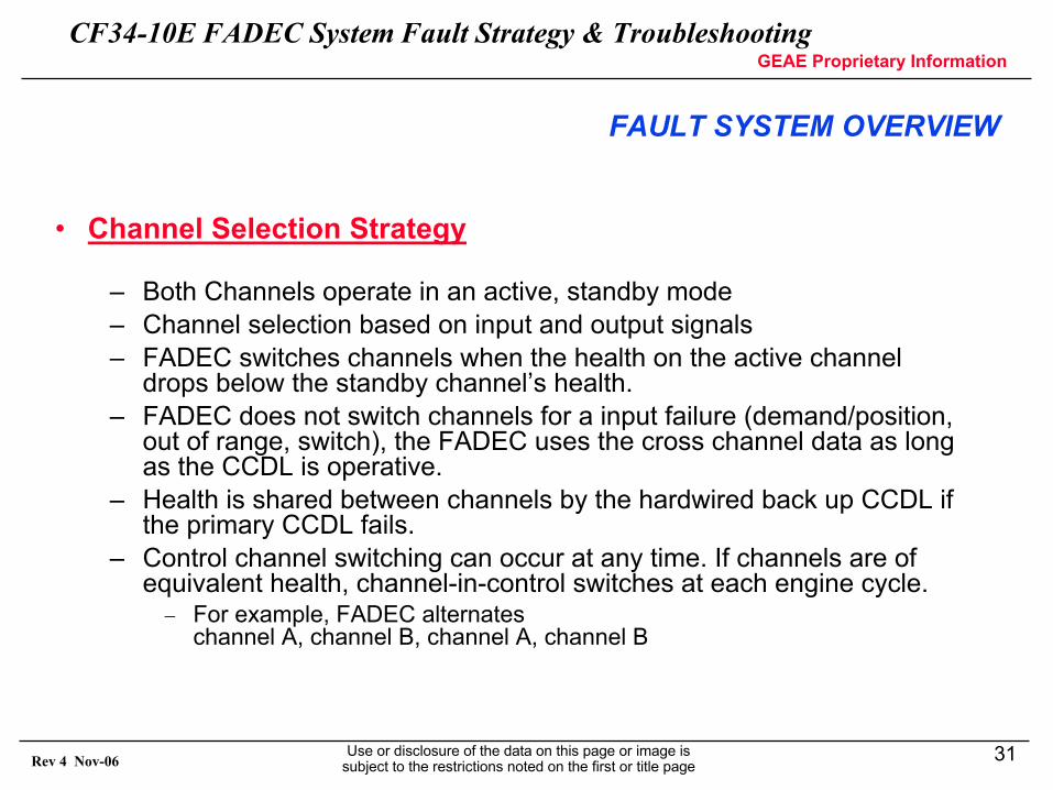
• Channel Selection Strategy
– Both Channels operate in an active, standby mode– Channel selection based on input and output signals– FADEC switches channels when the health on the active channel
drops below the standby channel’s health.– FADEC does not switch channels for a input failure (demand/position,
out of range, switch), the FADEC uses the cross channel data as long as the CCDL is operative.
– Health is shared between channels by the hardwired back up CCDL if the primary CCDL fails.
– Control channel switching can occur at any time. If channels are of equivalent health, channel-in-control switches at each engine cycle.− For example, FADEC alternates
channel A, channel B, channel A, channel B
FAULT SYSTEM OVERVIEW
CF34-10E FADEC System Fault Strategy & TroubleshootingGEAE Proprietary Information
Use or disclosure of the data on this page or image is subject to the restrictions noted on the first or title page
32Rev 4 Nov-06
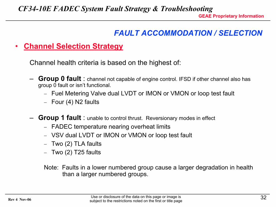
• Channel Selection Strategy
Channel health criteria is based on the highest of:
– Group 0 fault : channel not capable of engine control. IFSD if other channel also has group 0 fault or isn’t functional.− Fuel Metering Valve dual LVDT or IMON or VMON or loop test fault− Four (4) N2 faults
– Group 1 fault : unable to control thrust. Reversionary modes in effect− FADEC temperature nearing overheat limits− VSV dual LVDT or IMON or VMON or loop test fault− Two (2) TLA faults− Two (2) T25 faults
Note: Faults in a lower numbered group cause a larger degradation in health than a larger numbered groups.
FAULT ACCOMMODATION / SELECTION
CF34-10E FADEC System Fault Strategy & TroubleshootingGEAE Proprietary Information
Use or disclosure of the data on this page or image is subject to the restrictions noted on the first or title page
33Rev 4 Nov-06
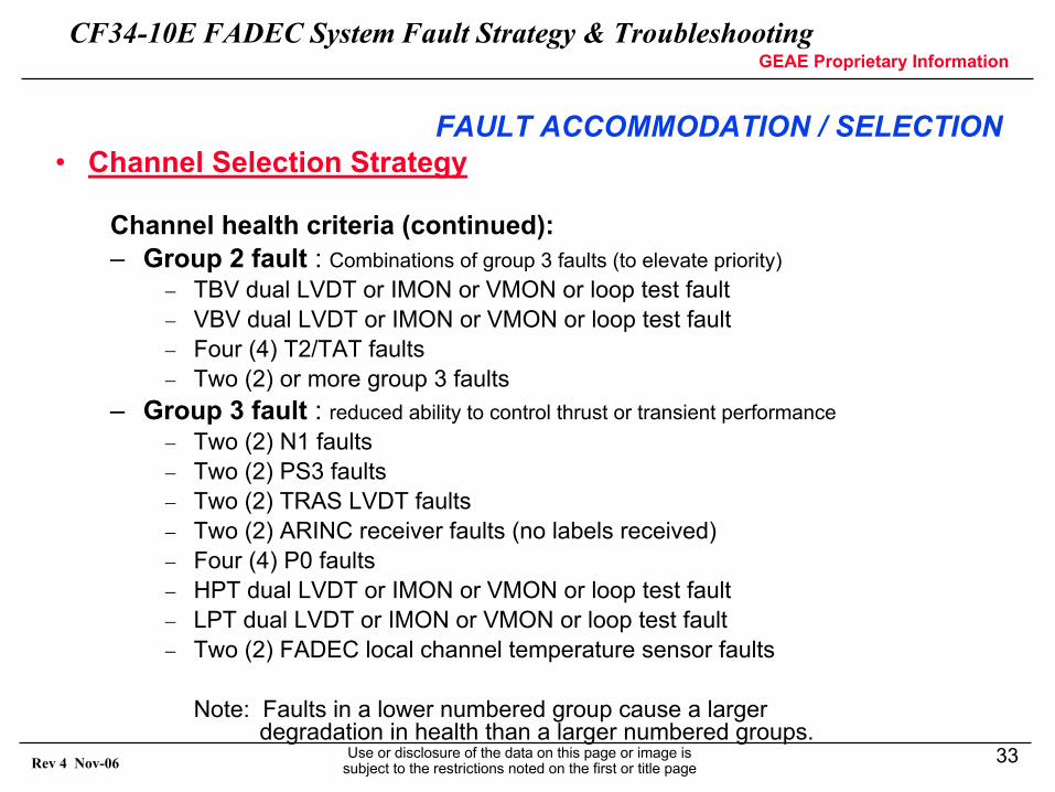
• Channel Selection Strategy
Channel health criteria (continued):– Group 2 fault : Combinations of group 3 faults (to elevate priority)
− TBV dual LVDT or IMON or VMON or loop test fault− VBV dual LVDT or IMON or VMON or loop test fault− Four (4) T2/TAT faults− Two (2) or more group 3 faults
– Group 3 fault : reduced ability to control thrust or transient performance− Two (2) N1 faults− Two (2) PS3 faults− Two (2) TRAS LVDT faults− Two (2) ARINC receiver faults (no labels received)− Four (4) P0 faults− HPT dual LVDT or IMON or VMON or loop test fault− LPT dual LVDT or IMON or VMON or loop test fault− Two (2) FADEC local channel temperature sensor faults
Note: Faults in a lower numbered group cause a larger degradation in health than a larger numbered groups.
FAULT ACCOMMODATION / SELECTION
CF34-10E FADEC System Fault Strategy & TroubleshootingGEAE Proprietary Information
Use or disclosure of the data on this page or image is subject to the restrictions noted on the first or title page
34Rev 4 Nov-06
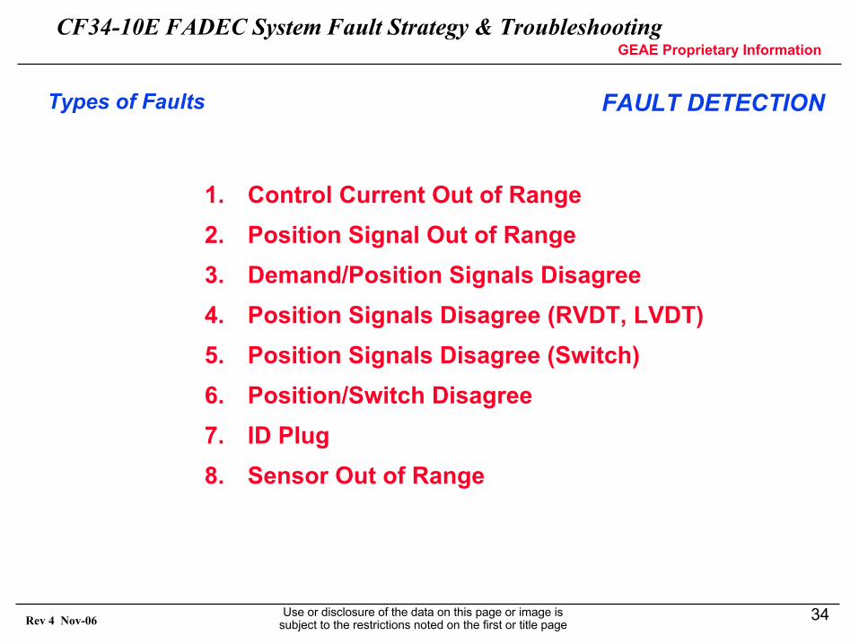
Types of Faults
1. Control Current Out of Range2. Position Signal Out of Range3. Demand/Position Signals Disagree4. Position Signals Disagree (RVDT, LVDT)5. Position Signals Disagree (Switch)6. Position/Switch Disagree7. ID Plug8. Sensor Out of Range
1. Control Current Out of Range2. Position Signal Out of Range3. Demand/Position Signals Disagree4. Position Signals Disagree (RVDT, LVDT)5. Position Signals Disagree (Switch)6. Position/Switch Disagree7. ID Plug8. Sensor Out of Range
FAULT DETECTION
CF34-10E FADEC System Fault Strategy & TroubleshootingGEAE Proprietary Information
Use or disclosure of the data on this page or image is subject to the restrictions noted on the first or title page
35Rev 4 Nov-06
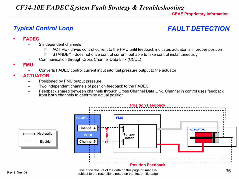
Typical Control Loop
Hydraulic
Electric
• FADEC– 2 independent channels
ACTIVE - drives control current to the FMU until feedback indicates actuator is in proper position STANDBY - does not drive control current, but able to take control instantaneously
– Communication through Cross Channel Data Link (CCDL)• FMU
– Converts FADEC control current input into fuel pressure output to the actuator• ACTUATOR
– Positioned by FMU output pressure– Two independent channels of position feedback to the FADEC– Feedback shared between channels through Cross Channel Data Link. Channel in control uses feedback
from both channels to determine actual position.
ACTUATOR
FMUFADEC
CCDL Torque Motor
Channel A
Channel B Dem
and
Position Feedback
Position Feedback
FAULT DETECTION
CF34-10E FADEC System Fault Strategy & TroubleshootingGEAE Proprietary Information
Use or disclosure of the data on this page or image is subject to the restrictions noted on the first or title page
36Rev 4 Nov-06
Control Loop Faults
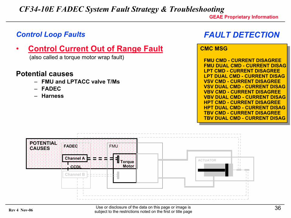
• Control Current Out of Range Fault(also called a torque motor wrap fault)
Potential causes– FMU and LPTACC valve T/Ms– FADEC– Harness
POTENTIALCAUSES
ACTUATORChannel A
Channel B
CCDL
FADEC
Torque Motor
FMU
CMC MSG
FMU CMD - CURRENT DISAGREEFMU DUAL CMD - CURRENT DISAGLPT CMD - CURRENT DISAGREELPT DUAL CMD - CURRENT DISAGVSV CMD - CURRENT DISAGREEVSV DUAL CMD - CURRENT DISAGVBV CMD - CURRENT DISAGREEVBV DUAL CMD - CURRENT DISAGHPT CMD - CURRENT DISAGREEHPT DUAL CMD - CURRENT DISAGTBV CMD - CURRENT DISAGREETBV DUAL CMD - CURRENT DISAG
FAULT DETECTION
CF34-10E FADEC System Fault Strategy & TroubleshootingGEAE Proprietary Information
Use or disclosure of the data on this page or image is subject to the restrictions noted on the first or title page
37Rev 4 Nov-06
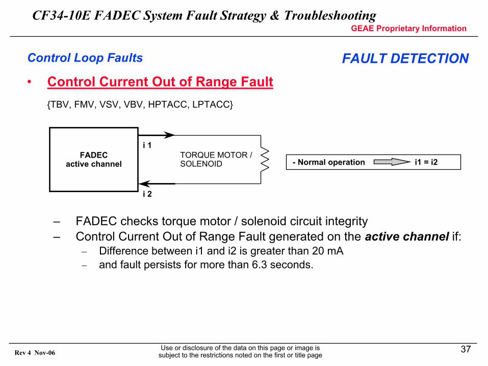
• Control Current Out of Range Fault {TBV, FMV, VSV, VBV, HPTACC, LPTACC}
– FADEC checks torque motor / solenoid circuit integrity– Control Current Out of Range Fault generated on the active channel if:
− Difference between i1 and i2 is greater than 20 mA− and fault persists for more than 6.3 seconds.
FADECactive channel
i 1
i 2
TORQUE MOTOR /SOLENOID - Normal operation i1 = i2
Control Loop Faults FAULT DETECTION
CF34-10E FADEC System Fault Strategy & TroubleshootingGEAE Proprietary Information
Use or disclosure of the data on this page or image is subject to the restrictions noted on the first or title page
38Rev 4 Nov-06
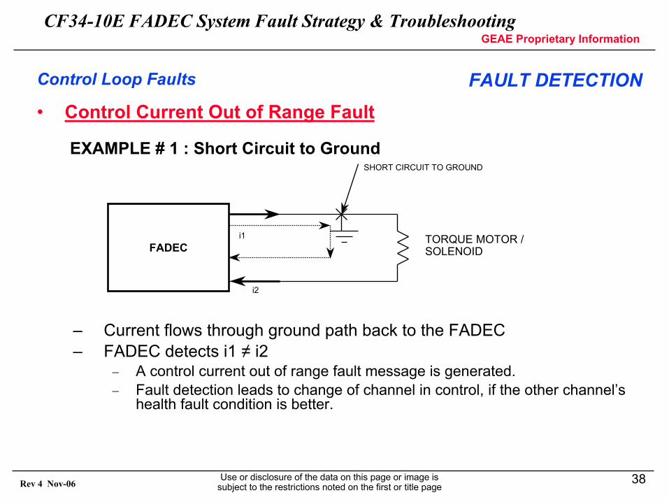
• Control Current Out of Range Fault
EXAMPLE # 1 : Short Circuit to Ground
– Current flows through ground path back to the FADEC– FADEC detects i1 ≠ i2
− A control current out of range fault message is generated.− Fault detection leads to change of channel in control, if the other channel’s
health fault condition is better.
FADECTORQUE MOTOR /SOLENOID
i1
i2
SHORT CIRCUIT TO GROUND
Control Loop Faults FAULT DETECTION
CF34-10E FADEC System Fault Strategy & TroubleshootingGEAE Proprietary Information
Use or disclosure of the data on this page or image is subject to the restrictions noted on the first or title page
39Rev 4 Nov-06
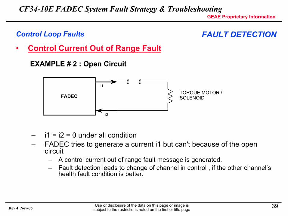
• Control Current Out of Range Fault
EXAMPLE # 2 : Open Circuit
– i1 = i2 = 0 under all condition– FADEC tries to generate a current i1 but can't because of the open
circuit– A control current out of range fault message is generated.– Fault detection leads to change of channel in control , if the other channel’s
health fault condition is better.
FADECTORQUE MOTOR /SOLENOID
i1
i2
Control Loop Faults FAULT DETECTION
CF34-10E FADEC System Fault Strategy & TroubleshootingGEAE Proprietary Information
Use or disclosure of the data on this page or image is subject to the restrictions noted on the first or title page
40Rev 4 Nov-06
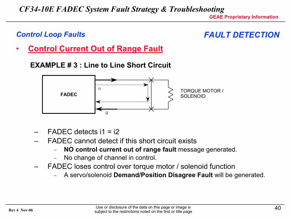
• Control Current Out of Range Fault
EXAMPLE # 3 : Line to Line Short Circuit
– FADEC detects i1 = i2– FADEC cannot detect if this short circuit exists
− NO control current out of range fault message generated.− No change of channel in control.
– FADEC loses control over torque motor / solenoid function− A servo/solenoid Demand/Position Disagree Fault will be generated.
FADECTORQUE MOTOR /SOLENOID
i1
i2
Control Loop Faults FAULT DETECTION
CF34-10E FADEC System Fault Strategy & TroubleshootingGEAE Proprietary Information
Use or disclosure of the data on this page or image is subject to the restrictions noted on the first or title page
41Rev 4 Nov-06
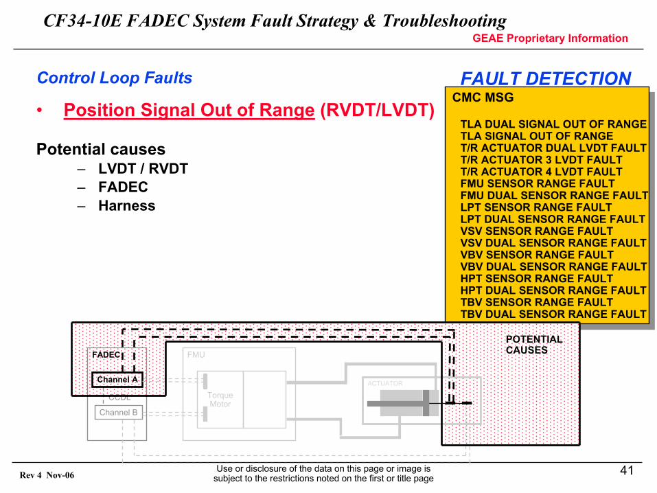
• Position Signal Out of Range (RVDT/LVDT)
Potential causes– LVDT / RVDT– FADEC– Harness
CMC MSG
TLA DUAL SIGNAL OUT OF RANGETLA SIGNAL OUT OF RANGET/R ACTUATOR DUAL LVDT FAULTT/R ACTUATOR 3 LVDT FAULTT/R ACTUATOR 4 LVDT FAULTFMU SENSOR RANGE FAULTFMU DUAL SENSOR RANGE FAULTLPT SENSOR RANGE FAULTLPT DUAL SENSOR RANGE FAULTVSV SENSOR RANGE FAULTVSV DUAL SENSOR RANGE FAULTVBV SENSOR RANGE FAULTVBV DUAL SENSOR RANGE FAULTHPT SENSOR RANGE FAULTHPT DUAL SENSOR RANGE FAULTTBV SENSOR RANGE FAULTTBV DUAL SENSOR RANGE FAULT
ACTUATORChannel A
Channel B
CCDL
FADEC
Torque Motor
FMU
POTENTIALCAUSES
Control Loop Faults FAULT DETECTION
CF34-10E FADEC System Fault Strategy & TroubleshootingGEAE Proprietary Information
Use or disclosure of the data on this page or image is subject to the restrictions noted on the first or title page
42Rev 4 Nov-06
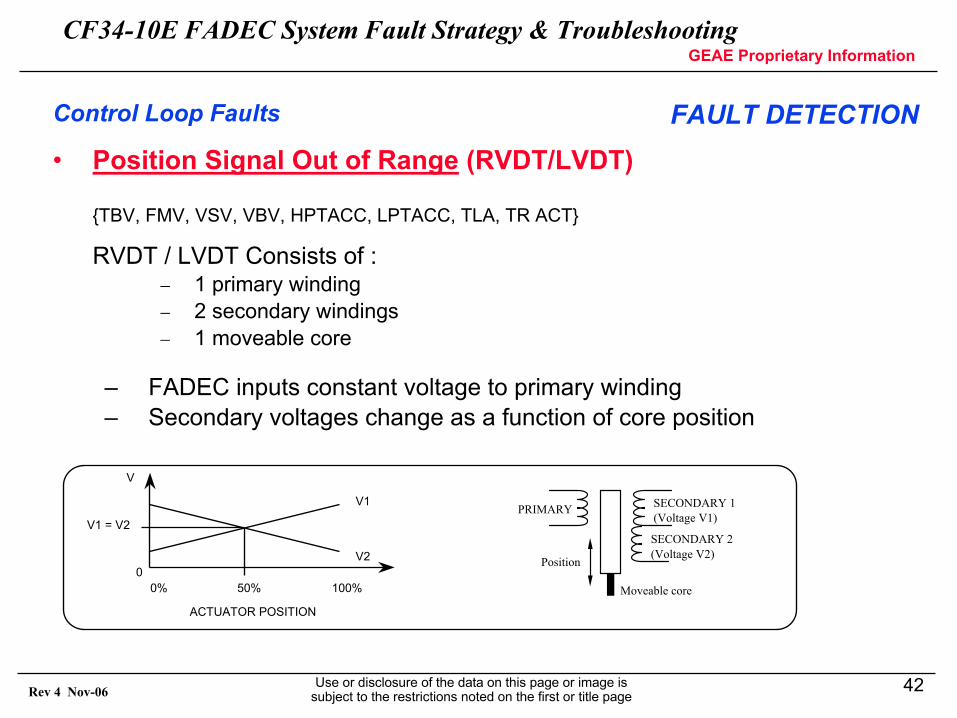
V1
V2
V1 = V2
0% 50% 100%0
V
ACTUATOR POSITION
PRIMARY SECONDARY 1(Voltage V1)
SECONDARY 2(Voltage V2)
Moveable core
Position
Control Loop Faults FAULT DETECTION• Position Signal Out of Range (RVDT/LVDT)
{TBV, FMV, VSV, VBV, HPTACC, LPTACC, TLA, TR ACT}
RVDT / LVDT Consists of :− 1 primary winding− 2 secondary windings− 1 moveable core
– FADEC inputs constant voltage to primary winding– Secondary voltages change as a function of core position
CF34-10E FADEC System Fault Strategy & TroubleshootingGEAE Proprietary Information
Use or disclosure of the data on this page or image is subject to the restrictions noted on the first or title page
43Rev 4 Nov-06
• Position Signal Out of Range (RVDT/LVDT)
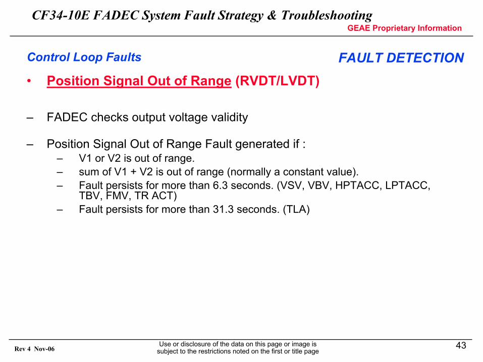
– FADEC checks output voltage validity
– Position Signal Out of Range Fault generated if :– V1 or V2 is out of range.– sum of V1 + V2 is out of range (normally a constant value).– Fault persists for more than 6.3 seconds. (VSV, VBV, HPTACC, LPTACC,
TBV, FMV, TR ACT) – Fault persists for more than 31.3 seconds. (TLA)
Control Loop Faults FAULT DETECTION
CF34-10E FADEC System Fault Strategy & TroubleshootingGEAE Proprietary Information
Use or disclosure of the data on this page or image is subject to the restrictions noted on the first or title page
44Rev 4 Nov-06
• Demand/Position Signals Disagree
Potential causes– valve– valve driver (fuel, electrical, air)– device operating valve
POTENTIALCAUSES
ACTUATORChannel A
Channel B
CCDL
FADEC
Torque Motor
FMU
CMC MSG
FMU CMD - POSITION DISAGREELPT CMD - POSITION DISGREEVSV CMD - POSITION DISAGREEVBV CMD - POSITION DISAGREEHPT CMD - POSITION DISAGREETBV CMD - POSITION DISAGREE
CMC MSG
FMU CMD - POSITION DISAGREELPT CMD - POSITION DISGREEVSV CMD - POSITION DISAGREEVBV CMD - POSITION DISAGREEHPT CMD - POSITION DISAGREETBV CMD - POSITION DISAGREE
Control Loop Faults FAULT DETECTION
CF34-10E FADEC System Fault Strategy & TroubleshootingGEAE Proprietary Information
Use or disclosure of the data on this page or image is subject to the restrictions noted on the first or title page
45Rev 4 Nov-06
• Demand/Position Signals Disagree
{TBV, FMV, VSV, VBV, HPTACC, LPTACC}
– FADEC checks if actual valve position agrees with demanded position.
– Demand/Position Signal Disagree fault generated on the active channel if :− Actual valve position disagrees with the demanded position.− Fault persists for more than 6.3 seconds.− There is no position switch fault at that moment.− There is no solenoid control current out of range fault at that moment.− Note the HPSOV is not controlled by the FMU.
Control Loop Faults FAULT DETECTION
CF34-10E FADEC System Fault Strategy & TroubleshootingGEAE Proprietary Information
Use or disclosure of the data on this page or image is subject to the restrictions noted on the first or title page
46Rev 4 Nov-06
• Demand/Position Signals Disagree
– A Demand and Position Signals Disagree Fault is also generated when a Torque Motor or Solenoid Line to Line short circuit condition exists.
– The current back to the FADEC is good, but the FMU torque motor is not actuating. (see Control Current Out of Range Fault-example #3).
Control Loop Faults FAULT DETECTION
CF34-10E FADEC System Fault Strategy & TroubleshootingGEAE Proprietary Information
Use or disclosure of the data on this page or image is subject to the restrictions noted on the first or title page
47Rev 4 Nov-06
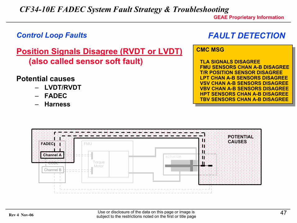
Position Signals Disagree (RVDT or LVDT)(also called sensor soft fault)
Potential causes– LVDT/RVDT– FADEC– Harness
CMC MSG
TLA SIGNALS DISAGREEFMU SENSORS CHAN A-B DISAGREET/R POSITION SENSOR DISAGREELPT CHAN A-B SENSORS DISAGREEVSV CHAN A-B SENSORS DISAGREEVBV CHAN A-B SENSORS DISAGREEHPT SENSORS CHAN A-B DISAGREETBV SENSORS CHAN A-B DISAGREE
CMC MSG
TLA SIGNALS DISAGREEFMU SENSORS CHAN A-B DISAGREET/R POSITION SENSOR DISAGREELPT CHAN A-B SENSORS DISAGREEVSV CHAN A-B SENSORS DISAGREEVBV CHAN A-B SENSORS DISAGREEHPT SENSORS CHAN A-B DISAGREETBV SENSORS CHAN A-B DISAGREE
Control Loop Faults FAULT DETECTION
ACTUATORChannel A
Channel B
CCDL
FADEC
Torque Motor
FMU
POTENTIALCAUSES
CF34-10E FADEC System Fault Strategy & TroubleshootingGEAE Proprietary Information
Use or disclosure of the data on this page or image is subject to the restrictions noted on the first or title page
48Rev 4 Nov-06
• Position Signals Disagree{TBV, FMV, VSV, VBV, HPTACC, LPTACC, TLA, TR ACT}
– Once the initial validity of the signal is established, the FADEC checks if the measured position agrees with the other channel’s measured position.
– Position signal disagree fault generated on the active channel if :− Sensed position disagrees by more than 5% with the other channel’s.− Fault persists for more than 6.3 seconds. (TLA, FMV, TR ACT)− Fault persists for more than 31.3 seconds. (LPTACC, VSV, VBV,
HPTACC, TBV)
Control Loop Faults FAULT DETECTION
CF34-10E FADEC System Fault Strategy & TroubleshootingGEAE Proprietary Information
Use or disclosure of the data on this page or image is subject to the restrictions noted on the first or title page
49Rev 4 Nov-06
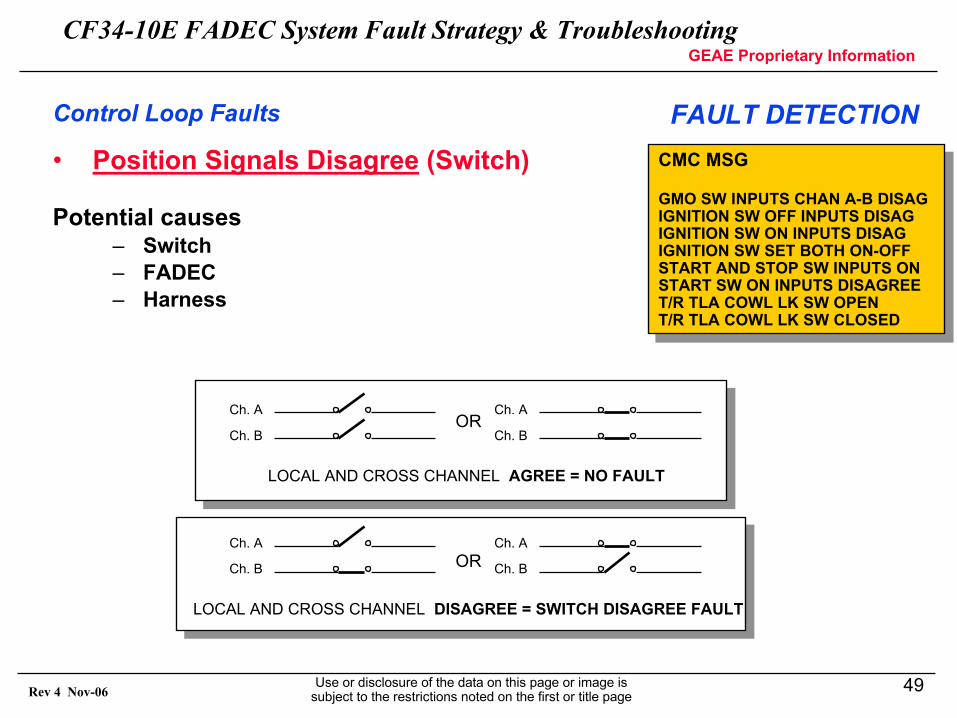
• Position Signals Disagree (Switch)
Potential causes– Switch– FADEC– Harness
CMC MSG
GMO SW INPUTS CHAN A-B DISAGIGNITION SW OFF INPUTS DISAGIGNITION SW ON INPUTS DISAGIGNITION SW SET BOTH ON-OFFSTART AND STOP SW INPUTS ONSTART SW ON INPUTS DISAGREET/R TLA COWL LK SW OPENT/R TLA COWL LK SW CLOSED
CMC MSG
GMO SW INPUTS CHAN A-B DISAGIGNITION SW OFF INPUTS DISAGIGNITION SW ON INPUTS DISAGIGNITION SW SET BOTH ON-OFFSTART AND STOP SW INPUTS ONSTART SW ON INPUTS DISAGREET/R TLA COWL LK SW OPENT/R TLA COWL LK SW CLOSED
Control Loop Faults FAULT DETECTION
LOCAL AND CROSS CHANNEL AGREE = NO FAULT
Ch. A
Ch. B
Ch. A
Ch. BOR
LOCAL AND CROSS CHANNEL DISAGREE = SWITCH DISAGREE FAULT
Ch. A
Ch. B
Ch. A
Ch. BOR
CF34-10E FADEC System Fault Strategy & TroubleshootingGEAE Proprietary Information
Use or disclosure of the data on this page or image is subject to the restrictions noted on the first or title page
50Rev 4 Nov-06
• Position Signals Disagree (Switch){GMO, IGN, START/STOP SW, TR LK SW}
– FADEC checks if both position switches agree.– Switch Disagree fault generated if :
− the position sensed by channels A and B is different.− fault persists for more than 6.3 seconds. (GMO, IGN, TR LK SW)− fault persists for more than 1.8 seconds. (START/STOP SW)
Control Loop Faults FAULT DETECTION
CF34-10E FADEC System Fault Strategy & TroubleshootingGEAE Proprietary Information
Use or disclosure of the data on this page or image is subject to the restrictions noted on the first or title page
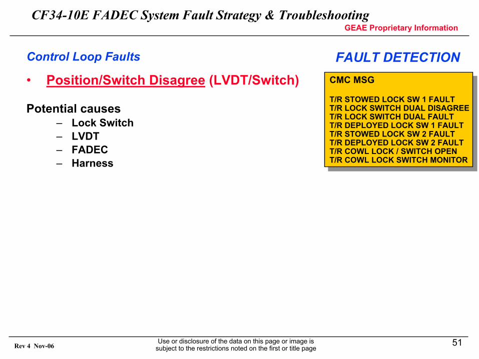
51Rev 4 Nov-06
• Position/Switch Disagree (LVDT/Switch)
Potential causes– Lock Switch– LVDT– FADEC– Harness
CMC MSG
T/R STOWED LOCK SW 1 FAULTT/R LOCK SWITCH DUAL DISAGREET/R LOCK SWITCH DUAL FAULTT/R DEPLOYED LOCK SW 1 FAULTT/R STOWED LOCK SW 2 FAULTT/R DEPLOYED LOCK SW 2 FAULTT/R COWL LOCK / SWITCH OPENT/R COWL LOCK SWITCH MONITOR
CMC MSG
T/R STOWED LOCK SW 1 FAULTT/R LOCK SWITCH DUAL DISAGREET/R LOCK SWITCH DUAL FAULTT/R DEPLOYED LOCK SW 1 FAULTT/R STOWED LOCK SW 2 FAULTT/R DEPLOYED LOCK SW 2 FAULTT/R COWL LOCK / SWITCH OPENT/R COWL LOCK SWITCH MONITOR
Control Loop Faults FAULT DETECTION
CF34-10E FADEC System Fault Strategy & TroubleshootingGEAE Proprietary Information
Use or disclosure of the data on this page or image is subject to the restrictions noted on the first or title page
52Rev 4 Nov-06
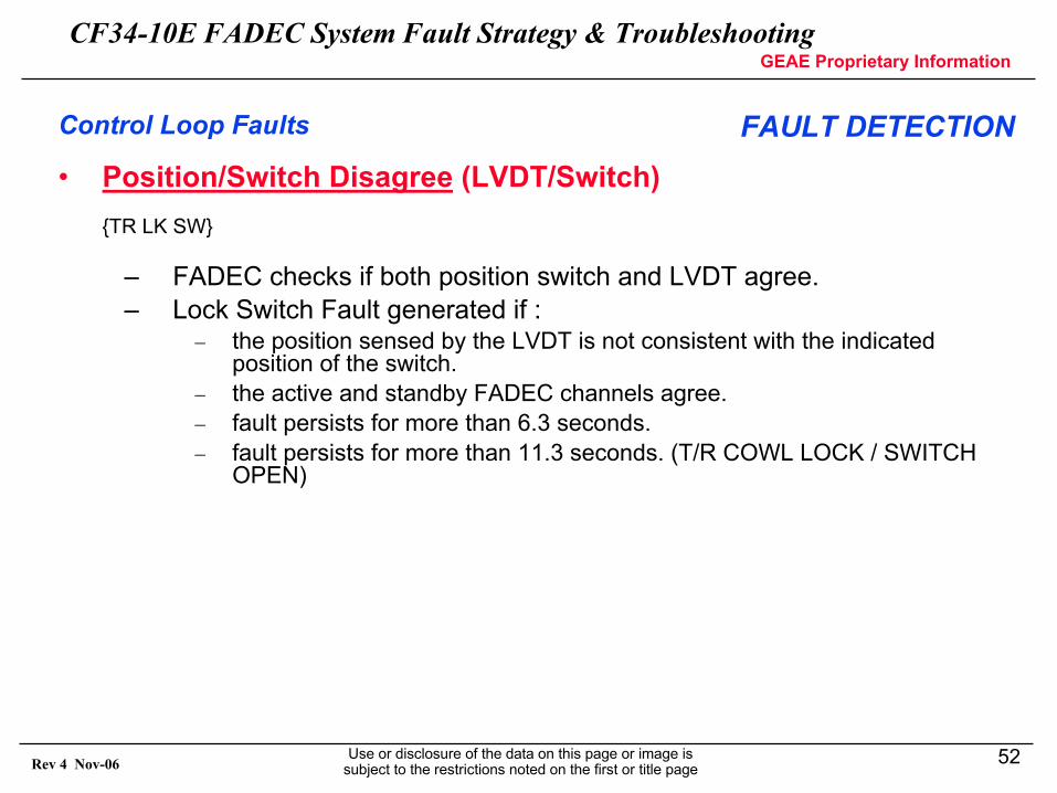
• Position/Switch Disagree (LVDT/Switch){TR LK SW}
– FADEC checks if both position switch and LVDT agree.– Lock Switch Fault generated if :
− the position sensed by the LVDT is not consistent with the indicated position of the switch.
− the active and standby FADEC channels agree.− fault persists for more than 6.3 seconds.− fault persists for more than 11.3 seconds. (T/R COWL LOCK / SWITCH
OPEN)
Control Loop Faults FAULT DETECTION
CF34-10E FADEC System Fault Strategy & TroubleshootingGEAE Proprietary Information
Use or disclosure of the data on this page or image is subject to the restrictions noted on the first or title page
53Rev 4 Nov-06
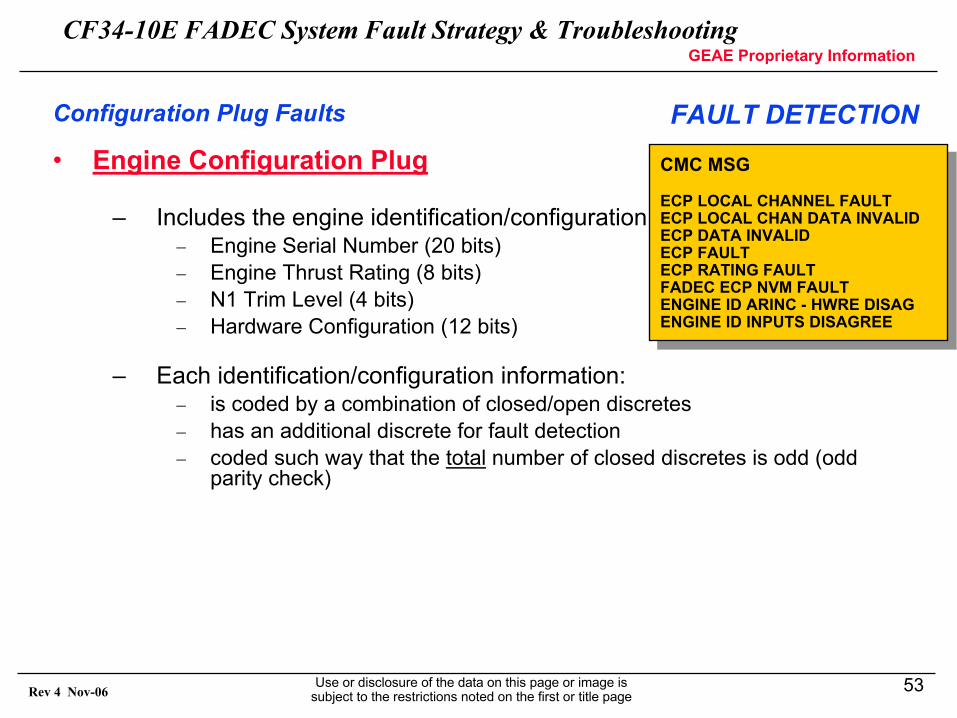
• Engine Configuration Plug
– Includes the engine identification/configuration:− Engine Serial Number (20 bits)− Engine Thrust Rating (8 bits)− N1 Trim Level (4 bits)− Hardware Configuration (12 bits)
– Each identification/configuration information:− is coded by a combination of closed/open discretes− has an additional discrete for fault detection − coded such way that the total number of closed discretes is odd (odd
parity check)
Configuration Plug Faults FAULT DETECTION
CMC MSG
ECP LOCAL CHANNEL FAULTECP LOCAL CHAN DATA INVALIDECP DATA INVALIDECP FAULTECP RATING FAULTFADEC ECP NVM FAULTENGINE ID ARINC - HWRE DISAGENGINE ID INPUTS DISAGREE
CMC MSG
ECP LOCAL CHANNEL FAULTECP LOCAL CHAN DATA INVALIDECP DATA INVALIDECP FAULTECP RATING FAULTFADEC ECP NVM FAULTENGINE ID ARINC - HWRE DISAGENGINE ID INPUTS DISAGREE
CF34-10E FADEC System Fault Strategy & TroubleshootingGEAE Proprietary Information
Use or disclosure of the data on this page or image is subject to the restrictions noted on the first or title page
54Rev 4 Nov-06
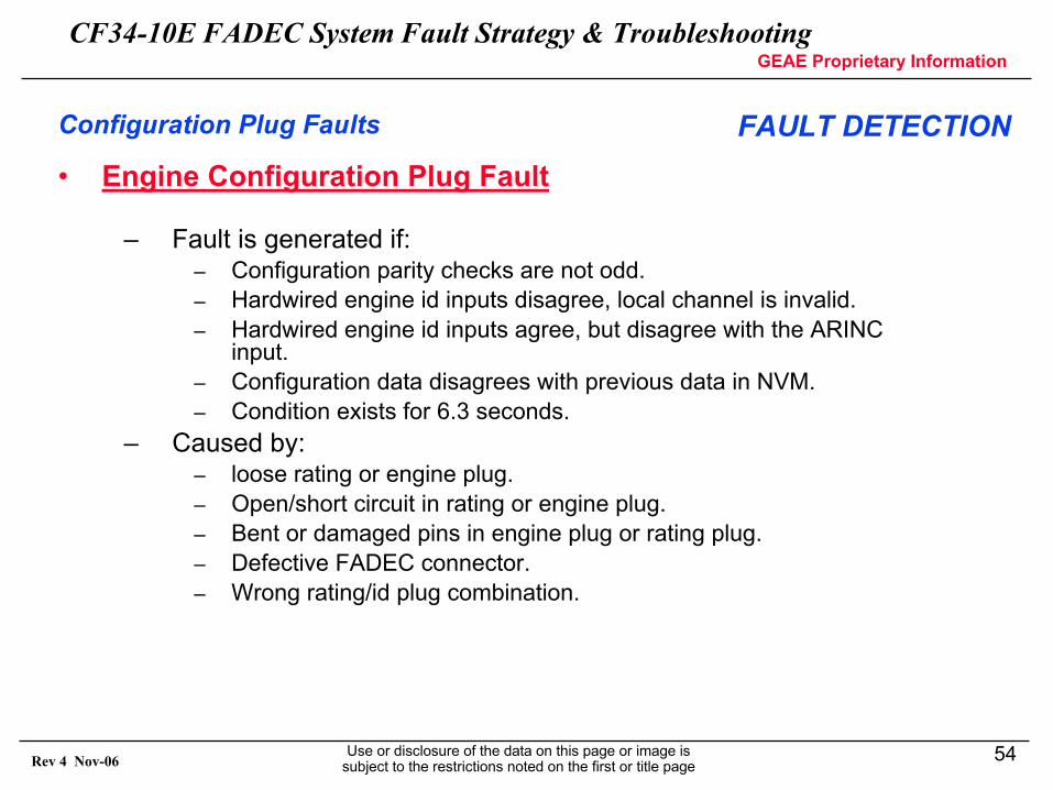
• Engine Configuration Plug Fault
– Fault is generated if:– Configuration parity checks are not odd.– Hardwired engine id inputs disagree, local channel is invalid.– Hardwired engine id inputs agree, but disagree with the ARINC
input.– Configuration data disagrees with previous data in NVM.– Condition exists for 6.3 seconds.
– Caused by:– loose rating or engine plug.– Open/short circuit in rating or engine plug.– Bent or damaged pins in engine plug or rating plug.– Defective FADEC connector.– Wrong rating/id plug combination.
Configuration Plug Faults FAULT DETECTION
CF34-10E FADEC System Fault Strategy & TroubleshootingGEAE Proprietary Information
Use or disclosure of the data on this page or image is subject to the restrictions noted on the first or title page
55Rev 4 Nov-06
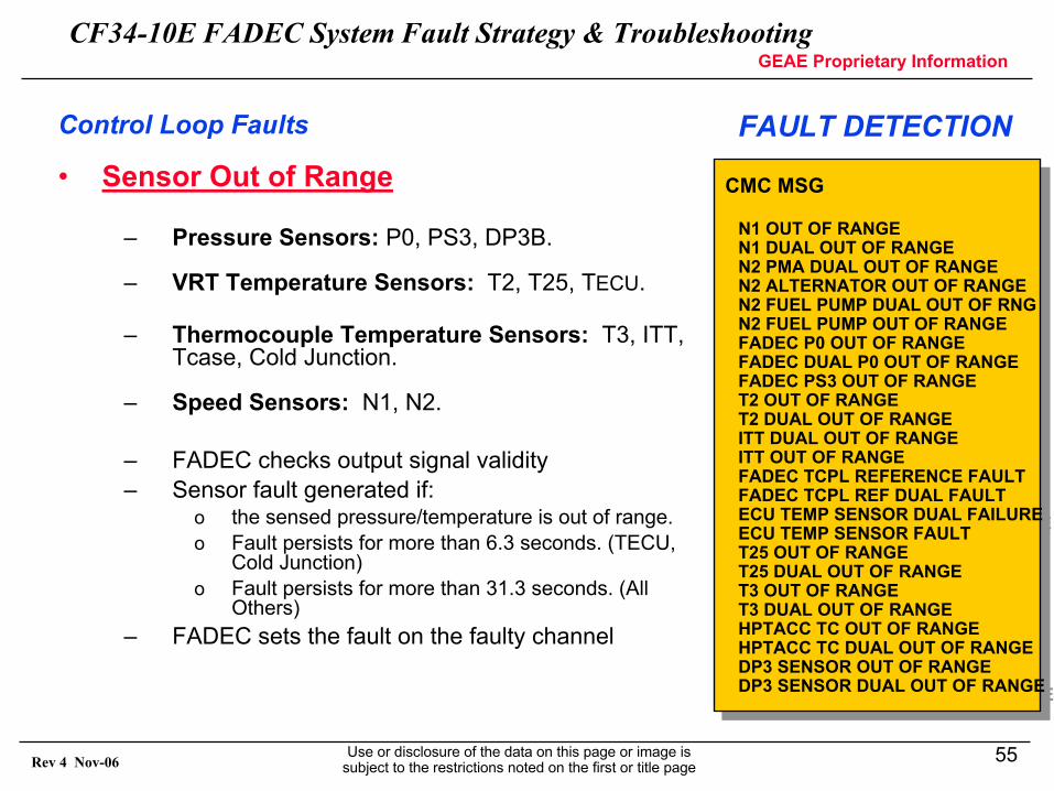
• Sensor Out of Range
– Pressure Sensors: P0, PS3, DP3B.
– VRT Temperature Sensors: T2, T25, TECU.
– Thermocouple Temperature Sensors: T3, ITT, Tcase, Cold Junction.
– Speed Sensors: N1, N2.
– FADEC checks output signal validity– Sensor fault generated if:
o the sensed pressure/temperature is out of range.o Fault persists for more than 6.3 seconds. (TECU,
Cold Junction)o Fault persists for more than 31.3 seconds. (All
Others)– FADEC sets the fault on the faulty channel
CMC MSG
N1 OUT OF RANGEN1 DUAL OUT OF RANGEN2 PMA DUAL OUT OF RANGEN2 ALTERNATOR OUT OF RANGEN2 FUEL PUMP DUAL OUT OF RNGN2 FUEL PUMP OUT OF RANGEFADEC P0 OUT OF RANGEFADEC DUAL P0 OUT OF RANGEFADEC PS3 OUT OF RANGET2 OUT OF RANGET2 DUAL OUT OF RANGEITT DUAL OUT OF RANGEITT OUT OF RANGEFADEC TCPL REFERENCE FAULTFADEC TCPL REF DUAL FAULTECU TEMP SENSOR DUAL FAILUREECU TEMP SENSOR FAULTT25 OUT OF RANGET25 DUAL OUT OF RANGET3 OUT OF RANGET3 DUAL OUT OF RANGEHPTACC TC OUT OF RANGEHPTACC TC DUAL OUT OF RANGEDP3 SENSOR OUT OF RANGEDP3 SENSOR DUAL OUT OF RANGE
Control Loop Faults FAULT DETECTION
CF34-10E FADEC System Fault Strategy & TroubleshootingGEAE Proprietary Information
Use or disclosure of the data on this page or image is subject to the restrictions noted on the first or title page
56Rev 4 Nov-06
FAULT ACCOMMODATION / SELECTION
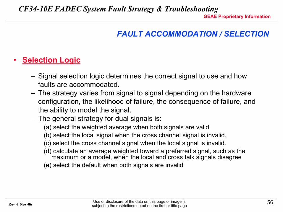
• Selection Logic
– Signal selection logic determines the correct signal to use and how faults are accommodated.
– The strategy varies from signal to signal depending on the hardware configuration, the likelihood of failure, the consequence of failure, and the ability to model the signal.
– The general strategy for dual signals is:(a) select the weighted average when both signals are valid.(b) select the local signal when the cross channel signal is invalid.(c) select the cross channel signal when the local signal is invalid.(d) calculate an average weighted toward a preferred signal, such as the
maximum or a model, when the local and cross talk signals disagree(e) select the default when both signals are invalid
CF34-10E FADEC System Fault Strategy & TroubleshootingGEAE Proprietary Information
Use or disclosure of the data on this page or image is subject to the restrictions noted on the first or title page
57Rev 4 Nov-06
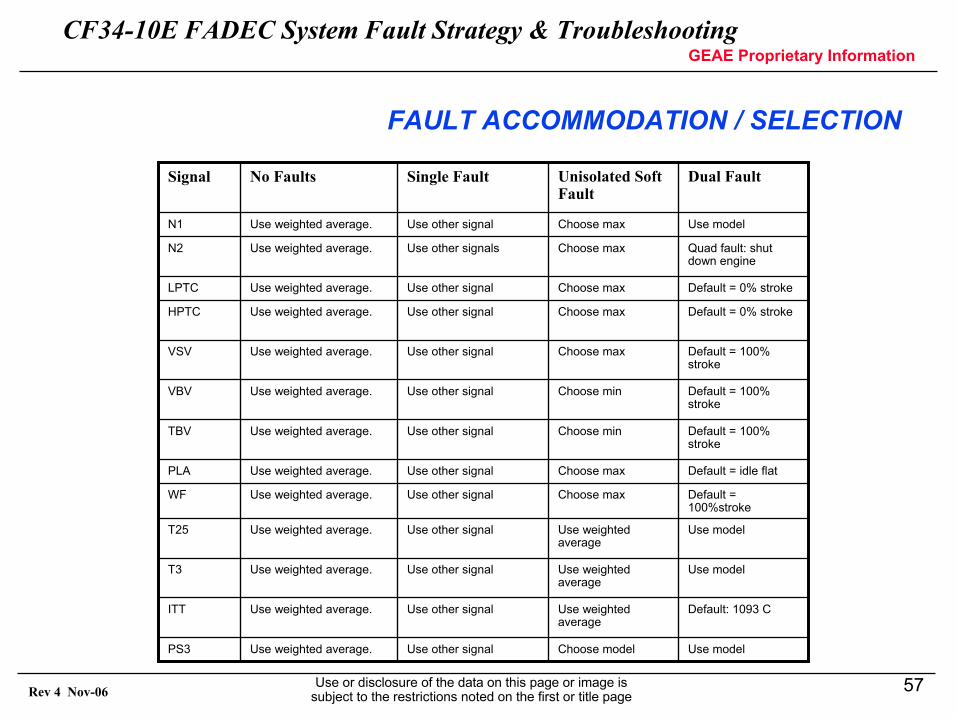
FAULT ACCOMMODATION / SELECTION
Dual FaultUnisolated Soft Fault
Single FaultNo FaultsSignal
Use modelChoose modelUse other signalUse weighted average.PS3
Default: 1093 CUse weighted average
Use other signalUse weighted average.ITT
Use modelUse weighted average
Use other signalUse weighted average.T3
Use modelUse weighted average
Use other signalUse weighted average.T25
Default = 100%stroke
Choose maxUse other signalUse weighted average.WF
Default = idle flatChoose maxUse other signalUse weighted average.PLA
Default = 100% stroke
Choose minUse other signalUse weighted average.TBV
Default = 100% stroke
Choose minUse other signalUse weighted average.VBV
Default = 100% stroke
Choose maxUse other signalUse weighted average.VSV
Default = 0% strokeChoose maxUse other signalUse weighted average.HPTC
Default = 0% strokeChoose maxUse other signalUse weighted average.LPTC
Quad fault: shut down engine
Choose maxUse other signalsUse weighted average.N2
Use modelChoose maxUse other signalUse weighted average.N1
CF34-10E FADEC System Fault Strategy & TroubleshootingGEAE Proprietary Information
Use or disclosure of the data on this page or image is subject to the restrictions noted on the first or title page
58Rev 4 Nov-06
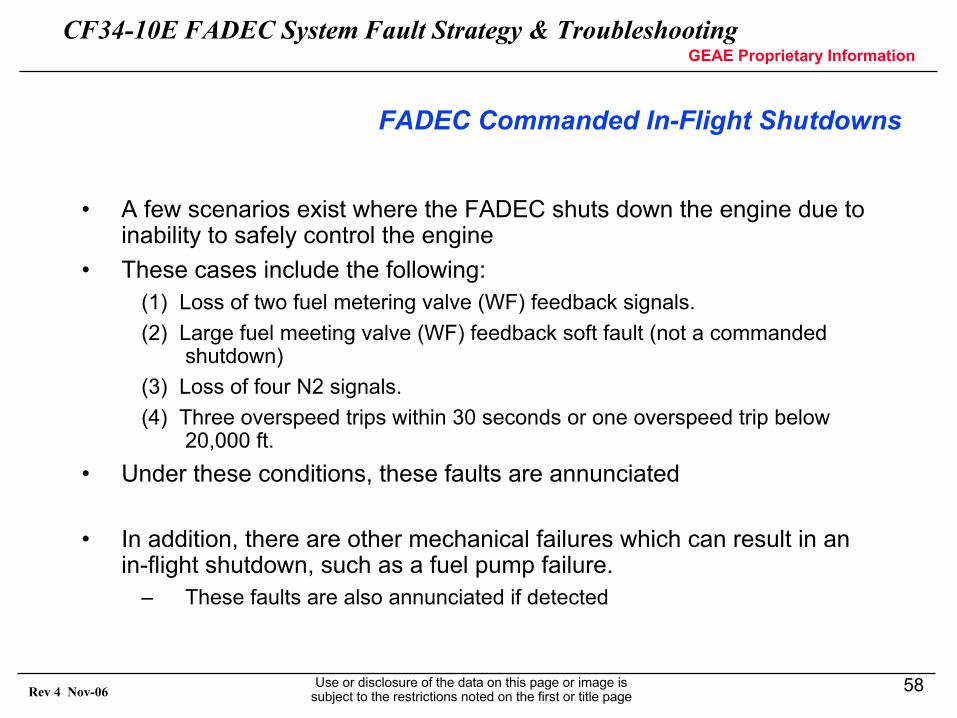
FADEC Commanded In-Flight Shutdowns
• A few scenarios exist where the FADEC shuts down the engine due to inability to safely control the engine
• These cases include the following:(1) Loss of two fuel metering valve (WF) feedback signals.(2) Large fuel meeting valve (WF) feedback soft fault (not a commanded
shutdown)(3) Loss of four N2 signals.(4) Three overspeed trips within 30 seconds or one overspeed trip below
20,000 ft.• Under these conditions, these faults are annunciated
• In addition, there are other mechanical failures which can result in an in-flight shutdown, such as a fuel pump failure.
– These faults are also annunciated if detected
CF34-10E FADEC System Fault Strategy & TroubleshootingGEAE Proprietary Information
Use or disclosure of the data on this page or image is subject to the restrictions noted on the first or title page
59Rev 4 Nov-06
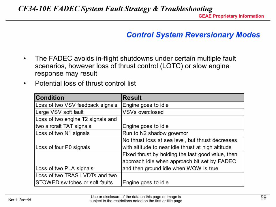
Control System Reversionary Modes
• The FADEC avoids in-flight shutdowns under certain multiple fault scenarios, however loss of thrust control (LOTC) or slow engine response may result
• Potential loss of thrust control list
Condition ResultLoss of two VSV feedback signals Engine goes to idleLarge VSV soft fault VSVs overclosedLoss of two engine T2 signals and two aircraft TAT signals Engine goes to idleLoss of two N1 signals Run to N2 shadow governor
Loss of four P0 signalsNo thrust loss at sea level, but thrust decreases with altitude to near idle thrust at high altitude
Loss of two PLA signals
Fixed thrust by holding the last good value, then approach idle when approach bit set by FADEC and then ground idle when WOW is true
Loss of two TRAS LVDTs and two STOWED switches or soft faults Engine goes to idle
CF34-10E FADEC System Fault Strategy & TroubleshootingGEAE Proprietary Information
Use or disclosure of the data on this page or image is subject to the restrictions noted on the first or title page
60Rev 4 Nov-06
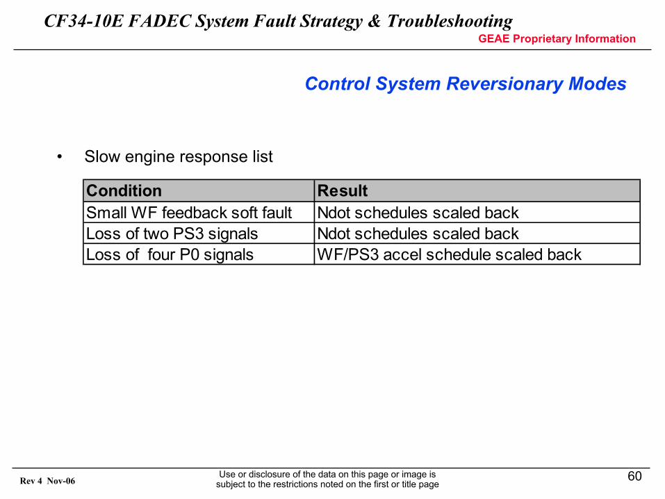
Control System Reversionary Modes
• Slow engine response list
Condition ResultSmall WF feedback soft fault Ndot schedules scaled backLoss of two PS3 signals Ndot schedules scaled backLoss of four P0 signals WF/PS3 accel schedule scaled back
CF34-10E FADEC System Fault Strategy & TroubleshootingGEAE Proprietary Information
Use or disclosure of the data on this page or image is subject to the restrictions noted on the first or title page
61Rev 4 Nov-06
Fault Annunciation
• EICAS Display• Multi Functional Display (MFD)• CMC Fault Display• Dispatch Criteria
CF34-10E FADEC System Fault Strategy & TroubleshootingGEAE Proprietary Information
Use or disclosure of the data on this page or image is subject to the restrictions noted on the first or title page
62Rev 4 Nov-06
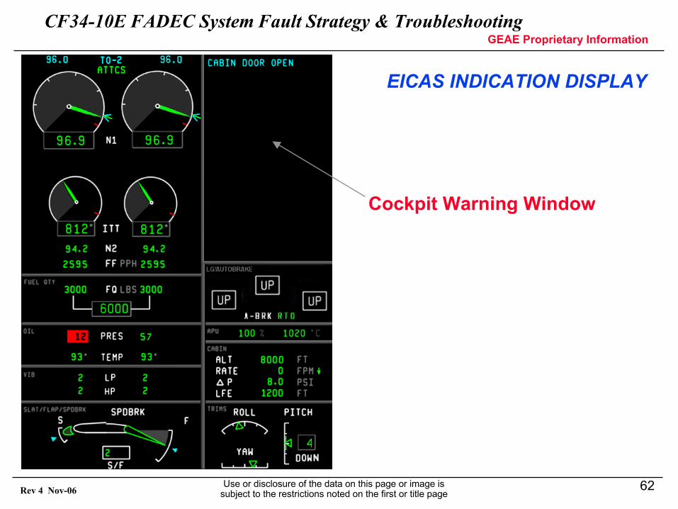
Cockpit Warning Window
EICAS INDICATION DISPLAY
CF34-10E FADEC System Fault Strategy & TroubleshootingGEAE Proprietary Information
Use or disclosure of the data on this page or image is subject to the restrictions noted on the first or title page
63Rev 4 Nov-06
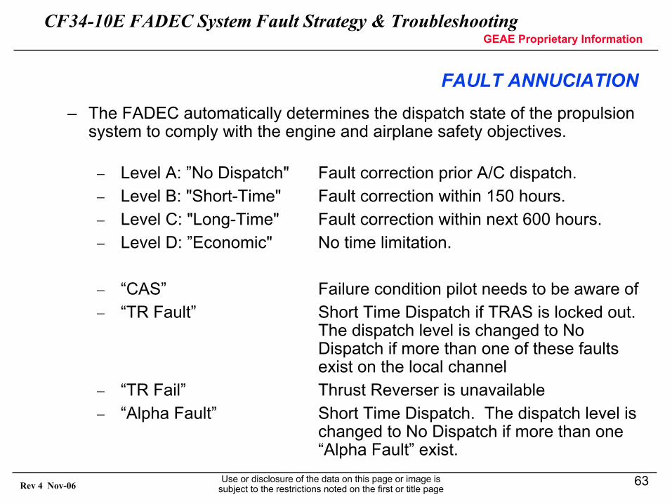
– The FADEC automatically determines the dispatch state of the propulsion system to comply with the engine and airplane safety objectives.
− Level A: ”No Dispatch" Fault correction prior A/C dispatch.− Level B: "Short-Time" Fault correction within 150 hours.− Level C: "Long-Time" Fault correction within next 600 hours.− Level D: ”Economic" No time limitation.
− “CAS” Failure condition pilot needs to be aware of− “TR Fault” Short Time Dispatch if TRAS is locked out.
The dispatch level is changed to NoDispatch if more than one of these faultsexist on the local channel
− “TR Fail” Thrust Reverser is unavailable− “Alpha Fault” Short Time Dispatch. The dispatch level is
changed to No Dispatch if more than one“Alpha Fault” exist.
FAULT ANNUCIATION
CF34-10E FADEC System Fault Strategy & TroubleshootingGEAE Proprietary Information
Use or disclosure of the data on this page or image is subject to the restrictions noted on the first or title page
64Rev 4 Nov-06
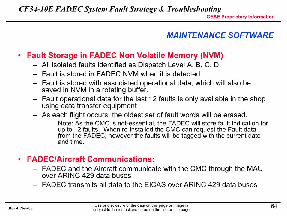
• Fault Storage in FADEC Non Volatile Memory (NVM)– All isolated faults identified as Dispatch Level A, B, C, D– Fault is stored in FADEC NVM when it is detected.– Fault is stored with associated operational data, which will also be
saved in NVM in a rotating buffer.– Fault operational data for the last 12 faults is only available in the shop
using data transfer equipment– As each flight occurs, the oldest set of fault words will be erased.
− Note: As the CMC is not-essential, the FADEC will store fault indication for up to 12 faults. When re-installed the CMC can request the Fault data from the FADEC, however the faults will be tagged with the current date and time.
• FADEC/Aircraft Communications:– FADEC and the Aircraft communicate with the CMC through the MAU
over ARINC 429 data buses– FADEC transmits all data to the EICAS over ARINC 429 data buses
MAINTENANCE SOFTWARE
CF34-10E FADEC System Fault Strategy & TroubleshootingGEAE Proprietary Information
Use or disclosure of the data on this page or image is subject to the restrictions noted on the first or title page
65Rev 4 Nov-06
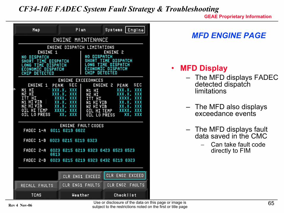
MFD ENGINE PAGE
• MFD Display– The MFD displays FADEC
detected dispatch limitations
– The MFD also displays exceedance events
– The MFD displays fault data saved in the CMC− Can take fault code
directly to FIM
CF34-10E FADEC System Fault Strategy & TroubleshootingGEAE Proprietary Information
Use or disclosure of the data on this page or image is subject to the restrictions noted on the first or title page
66Rev 4 Nov-06
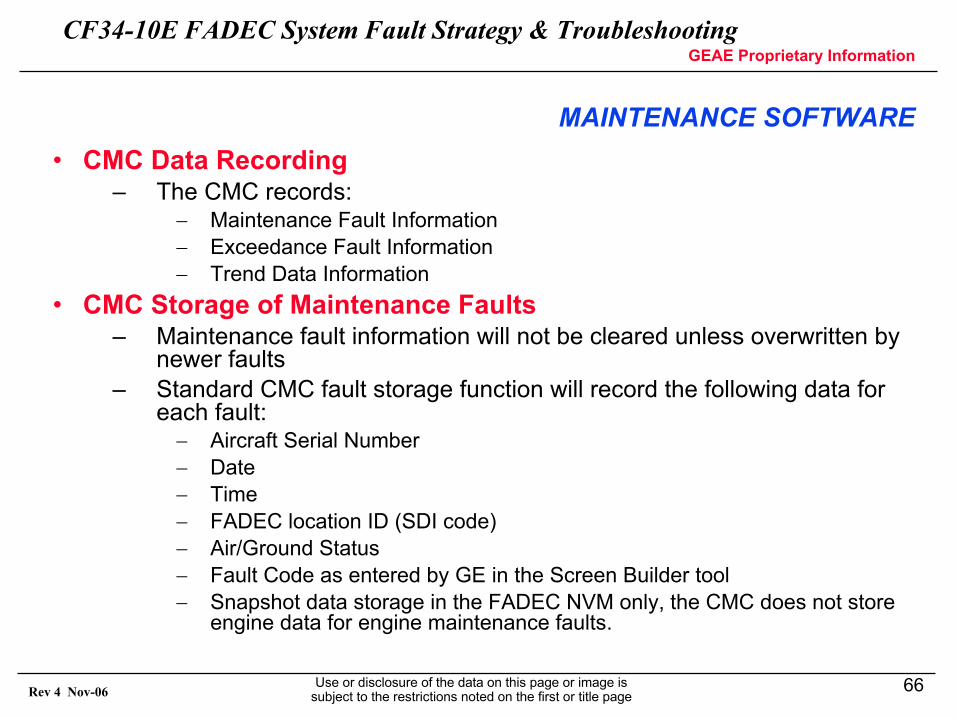
MAINTENANCE SOFTWARE• CMC Data Recording
– The CMC records:− Maintenance Fault Information− Exceedance Fault Information− Trend Data Information
• CMC Storage of Maintenance Faults– Maintenance fault information will not be cleared unless overwritten by
newer faults– Standard CMC fault storage function will record the following data for
each fault:− Aircraft Serial Number− Date− Time− FADEC location ID (SDI code)− Air/Ground Status− Fault Code as entered by GE in the Screen Builder tool− Snapshot data storage in the FADEC NVM only, the CMC does not store
engine data for engine maintenance faults.
CF34-10E FADEC System Fault Strategy & TroubleshootingGEAE Proprietary Information
Use or disclosure of the data on this page or image is subject to the restrictions noted on the first or title page
67Rev 4 Nov-06
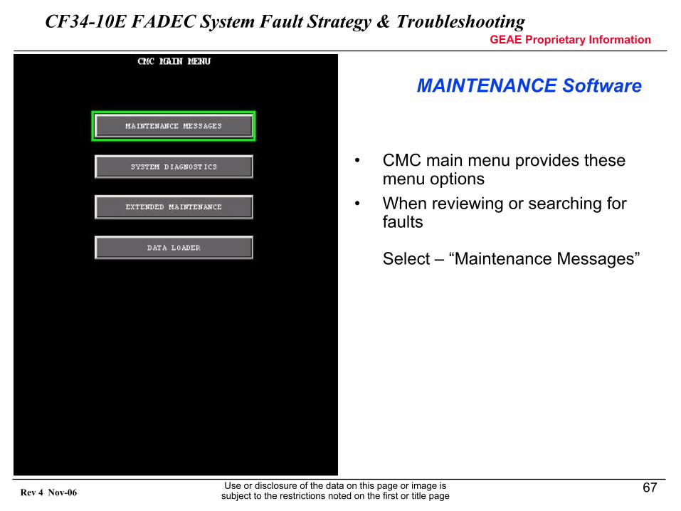
MAINTENANCE Software
• CMC main menu provides these menu options
• When reviewing or searching for faults
Select – “Maintenance Messages”
CF34-10E FADEC System Fault Strategy & TroubleshootingGEAE Proprietary Information
Use or disclosure of the data on this page or image is subject to the restrictions noted on the first or title page
68Rev 4 Nov-06
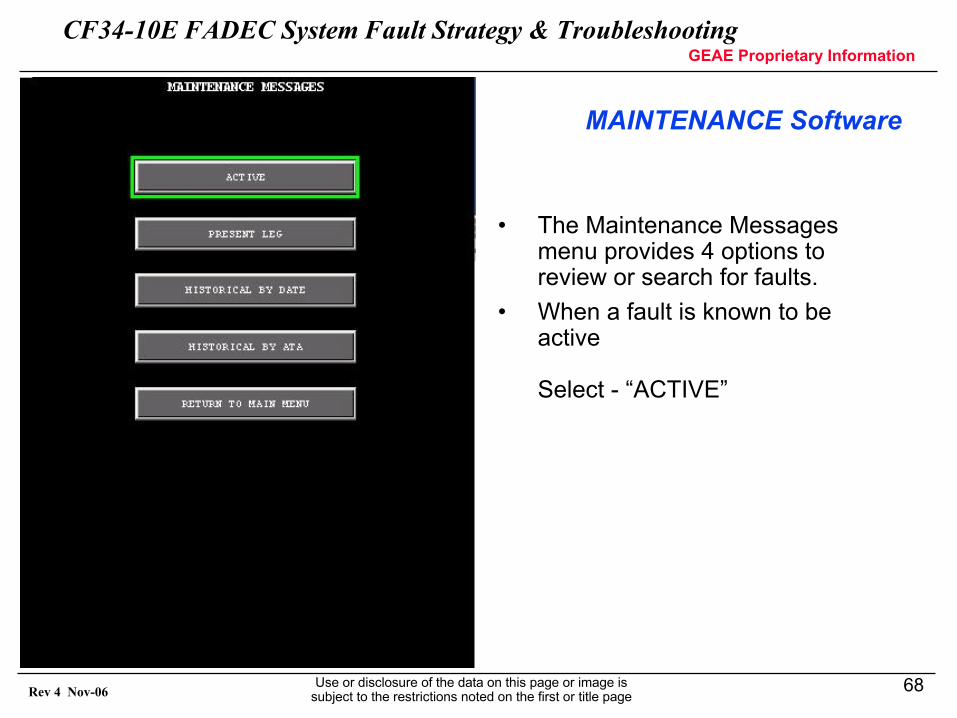
MAINTENANCE Software
• The Maintenance Messages menu provides 4 options to review or search for faults.
• When a fault is known to be active
Select - “ACTIVE”
CF34-10E FADEC System Fault Strategy & TroubleshootingGEAE Proprietary Information
Use or disclosure of the data on this page or image is subject to the restrictions noted on the first or title page
69Rev 4 Nov-06
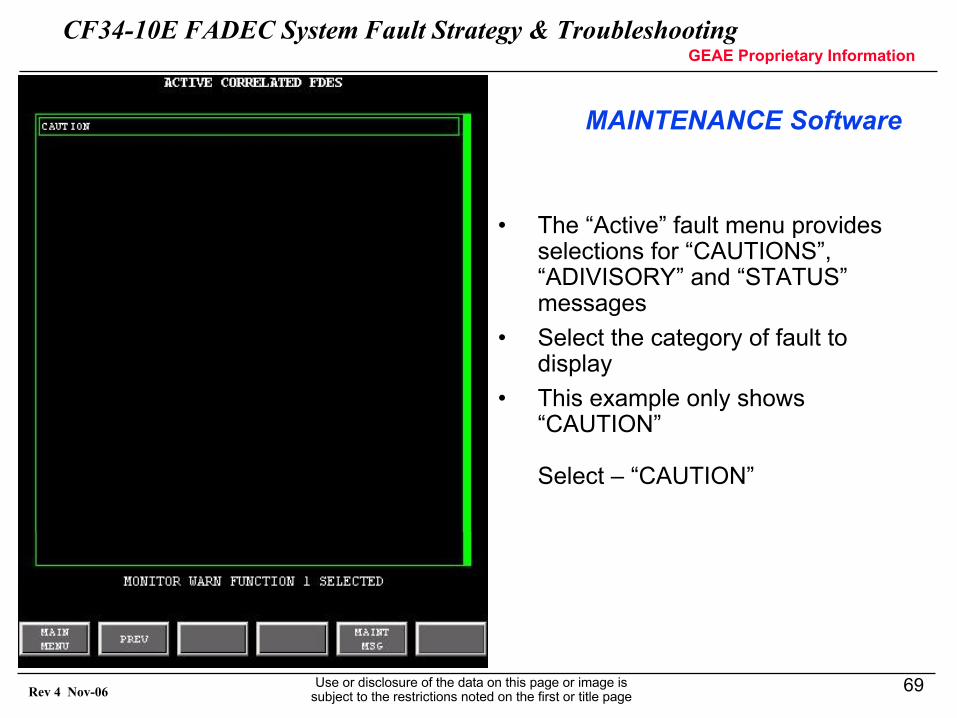
MAINTENANCE Software
• The “Active” fault menu provides selections for “CAUTIONS”, “ADIVISORY” and “STATUS” messages
• Select the category of fault to display
• This example only shows “CAUTION”
Select – “CAUTION”
CF34-10E FADEC System Fault Strategy & TroubleshootingGEAE Proprietary Information
Use or disclosure of the data on this page or image is subject to the restrictions noted on the first or title page
70Rev 4 Nov-06
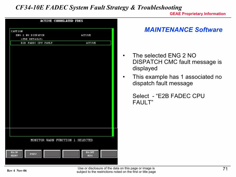
MAINTENANCE Software
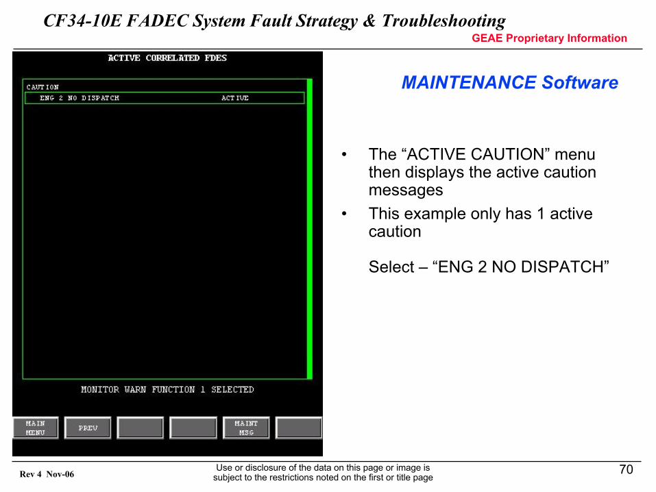
• The “ACTIVE CAUTION” menu then displays the active caution messages
• This example only has 1 active caution
Select – “ENG 2 NO DISPATCH”
CF34-10E FADEC System Fault Strategy & TroubleshootingGEAE Proprietary Information
Use or disclosure of the data on this page or image is subject to the restrictions noted on the first or title page
71Rev 4 Nov-06
MAINTENANCE Software
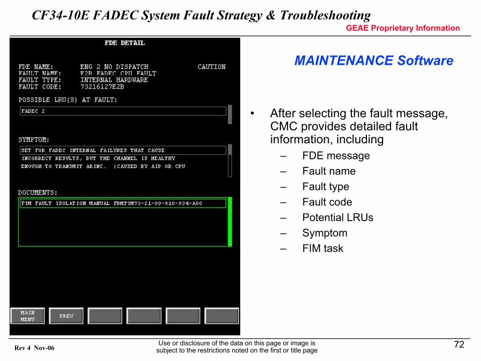
• The selected ENG 2 NO DISPATCH CMC fault message is displayed
• This example has 1 associated no dispatch fault message
Select - “E2B FADEC CPU FAULT”
CF34-10E FADEC System Fault Strategy & TroubleshootingGEAE Proprietary Information
Use or disclosure of the data on this page or image is subject to the restrictions noted on the first or title page
72Rev 4 Nov-06
MAINTENANCE Software
• After selecting the fault message, CMC provides detailed fault information, including
– FDE message– Fault name– Fault type– Fault code– Potential LRUs– Symptom– FIM task
CF34-10E FADEC System Fault Strategy & TroubleshootingGEAE Proprietary Information
Use or disclosure of the data on this page or image is subject to the restrictions noted on the first or title page
73Rev 4 Nov-06
• CMC Storage of Exceedance Data– Exceedance maintenance faults will not be cleared unless
commanded to be reset from the MFD– The CMC will save the following data for an exceedance:
− Minimum of 2 seconds of pre-event data− Minimum of 30 seconds of post-event data− Peak and duration information of the exceedance− Flight Phase− Flight Leg− FADEC Location ID (SDI Code)− Time− Date− Aircraft Serial Number
– The CMC will store at least 50 exceedance data sets
Note: The FADEC will save exceedance peak and duration data in NVM. If the CMC is not available during the flight, this will be the only data available to document the exceedance.
MAINTENANCE SOFTWARE
CF34-10E FADEC System Fault Strategy & TroubleshootingGEAE Proprietary Information
Use or disclosure of the data on this page or image is subject to the restrictions noted on the first or title page
74Rev 4 Nov-06
• CMC Storage of Trend Data– Up to 200 trend points
(allowing for a weekly data download interval assuming 10 flights a day, 3 points a flight, 7 day operation)
– The CMC will save the following trend data information:− Trend data point− Flight Phase− Flight Leg− FADEC Location ID (SDI Code)− Time− Date− Aircraft Serial Number
MAINTENANCE SOFTWARE
CF34-10E FADEC System Fault Strategy & TroubleshootingGEAE Proprietary Information
Use or disclosure of the data on this page or image is subject to the restrictions noted on the first or title page
75Rev 4 Nov-06
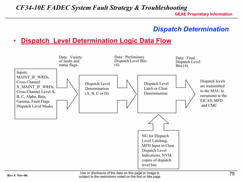
Dispatch Determination • Dispatch Level Determination Logic Data Flow
Inputs:MAINT_IF_WRDs,Cross ChannelX_MAINT_IF_WRDs,Cross Channel Level A,B, C, Alpha, Beta,Gamma, Fault FlagsDispatch Level Masks
Dispatch LevelDetermination(A, B, C or D)
Dispatch LevelLatch or ClearDetermination
NG for DispatchLevel Latching,MFD Input to ClearDispatch LevelIndications, NVMcopies of dispatchlevel bits
Dispatch levelsare transmittedto the MAU toretransmit to theEICAS, MFDand CMC
Data: Variety of faults and status flags.
Data: Preliminary Dispatch Level Bits (4).
Data: Final Dispatch Level Bits (4).
CF34-10E FADEC System Fault Strategy & TroubleshootingGEAE Proprietary Information
Use or disclosure of the data on this page or image is subject to the restrictions noted on the first or title page
76Rev 4 Nov-06
DISPATCH CRITERIA
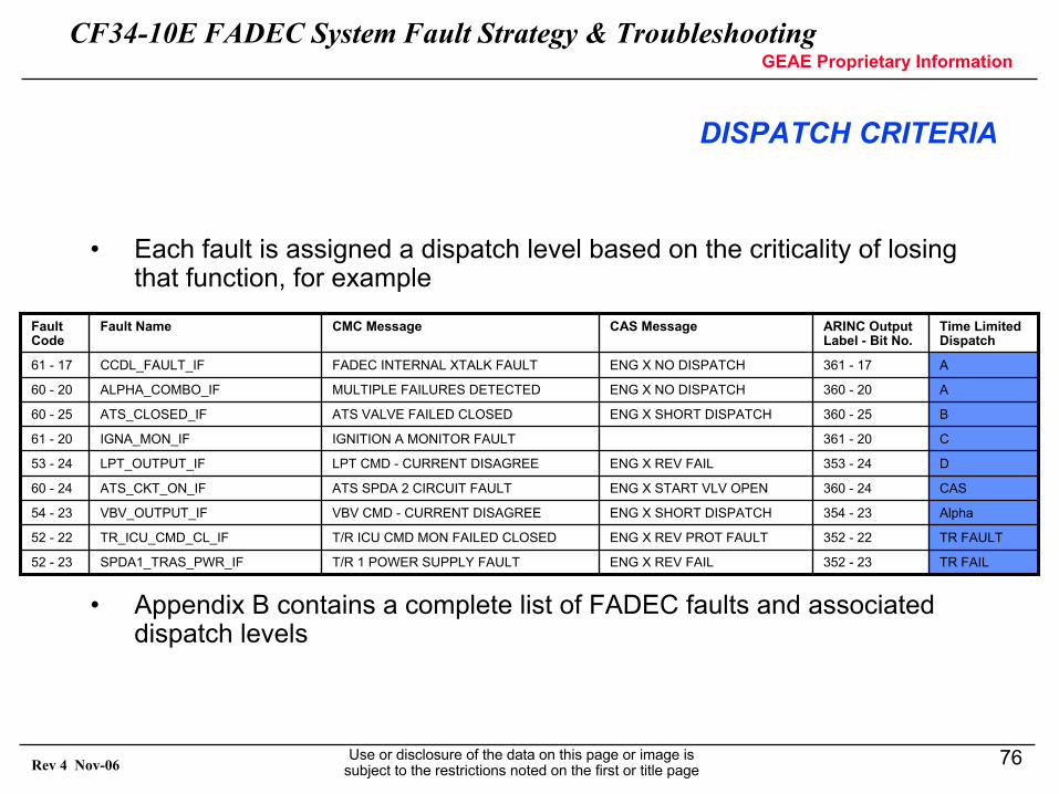
• Each fault is assigned a dispatch level based on the criticality of losing that function, for example
• Appendix B contains a complete list of FADEC faults and associated dispatch levels
TR FAULT352 - 22ENG X REV PROT FAULTT/R ICU CMD MON FAILED CLOSEDTR_ICU_CMD_CL_IF52 - 22
TR FAIL352 - 23ENG X REV FAILT/R 1 POWER SUPPLY FAULTSPDA1_TRAS_PWR_IF52 - 23
Alpha354 - 23ENG X SHORT DISPATCHVBV CMD - CURRENT DISAGREEVBV_OUTPUT_IF54 - 23
CAS360 - 24ENG X START VLV OPENATS SPDA 2 CIRCUIT FAULTATS_CKT_ON_IF60 - 24
D353 - 24ENG X REV FAILLPT CMD - CURRENT DISAGREELPT_OUTPUT_IF53 - 24
C361 - 20IGNITION A MONITOR FAULTIGNA_MON_IF61 - 20
A360 - 20ENG X NO DISPATCHMULTIPLE FAILURES DETECTEDALPHA_COMBO_IF60 - 20
B360 - 25ENG X SHORT DISPATCHATS VALVE FAILED CLOSEDATS_CLOSED_IF60 - 25
A361 - 17ENG X NO DISPATCHFADEC INTERNAL XTALK FAULTCCDL_FAULT_IF61 - 17
Time Limited Dispatch
ARINC Output Label - Bit No.
CAS MessageCMC MessageFault NameFault Code
CF34-10E FADEC System Fault Strategy & TroubleshootingGEAE Proprietary Information
Use or disclosure of the data on this page or image is subject to the restrictions noted on the first or title page
77Rev 4 Nov-06
Dispatch ANNUCIATION
• The FADEC performs diagnostics on its input data to determine if any failures exist.
• If a failure exists, and if the failure is one that the pilot needs to be aware of, a message or indication will be displayed to the pilot on the EICAS. For example
– “ENG x FAIL”, caution message (masked during takeoff)indicates an uncommanded engine shutdown has occurred.
• If a failure condition is not severe and does not directly affect engine operation, the engine dispatch level is calculated and a message will be transmitted for display on the appropriate device (EICAS or MFD)For example,
– “ENG x NO DISPATCH”, caution message − masked from takeoff until 5 seconds after landing− indicates a NO DISPATCH fault exists
– “ENG x SHORT DISPATCH”, advisory message − masked from takeoff until 5 seconds after landing
NOTE: Due to masking . . . Fault may not have occurred when noted by the pilot
CF34-10E FADEC System Fault Strategy & TroubleshootingGEAE Proprietary Information
Use or disclosure of the data on this page or image is subject to the restrictions noted on the first or title page
78Rev 4 Nov-06
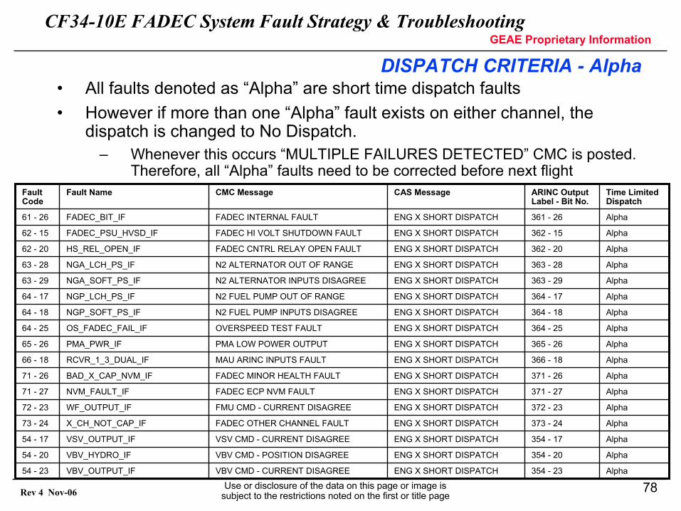
DISPATCH CRITERIA - Alpha• All faults denoted as “Alpha” are short time dispatch faults• However if more than one “Alpha” fault exists on either channel, the
dispatch is changed to No Dispatch.– Whenever this occurs “MULTIPLE FAILURES DETECTED” CMC is posted.
Therefore, all “Alpha” faults need to be corrected before next flight
Alpha354 - 17ENG X SHORT DISPATCHVSV CMD - CURRENT DISAGREEVSV_OUTPUT_IF54 - 17
Alpha354 - 20ENG X SHORT DISPATCHVBV CMD - POSITION DISAGREEVBV_HYDRO_IF54 - 20
Alpha354 - 23ENG X SHORT DISPATCHVBV CMD - CURRENT DISAGREEVBV_OUTPUT_IF54 - 23
Alpha373 - 24ENG X SHORT DISPATCHFADEC OTHER CHANNEL FAULTX_CH_NOT_CAP_IF73 - 24
Alpha371 - 26ENG X SHORT DISPATCHFADEC MINOR HEALTH FAULTBAD_X_CAP_NVM_IF71 - 26
Alpha371 - 27ENG X SHORT DISPATCHFADEC ECP NVM FAULTNVM_FAULT_IF71 - 27
Alpha372 - 23ENG X SHORT DISPATCHFMU CMD - CURRENT DISAGREEWF_OUTPUT_IF72 - 23
Alpha365 - 26ENG X SHORT DISPATCHPMA LOW POWER OUTPUTPMA_PWR_IF65 - 26
Alpha366 - 18ENG X SHORT DISPATCHMAU ARINC INPUTS FAULTRCVR_1_3_DUAL_IF66 - 18
Alpha363 - 28ENG X SHORT DISPATCHN2 ALTERNATOR OUT OF RANGENGA_LCH_PS_IF63 - 28
Alpha363 - 29ENG X SHORT DISPATCHN2 ALTERNATOR INPUTS DISAGREENGA_SOFT_PS_IF63 - 29
Alpha364 - 17ENG X SHORT DISPATCHN2 FUEL PUMP OUT OF RANGENGP_LCH_PS_IF64 - 17
Alpha364 - 18ENG X SHORT DISPATCHN2 FUEL PUMP INPUTS DISAGREENGP_SOFT_PS_IF64 - 18
Alpha364 - 25ENG X SHORT DISPATCHOVERSPEED TEST FAULTOS_FADEC_FAIL_IF64 - 25
Alpha362 - 20ENG X SHORT DISPATCHFADEC CNTRL RELAY OPEN FAULTHS_REL_OPEN_IF62 - 20
Alpha362 - 15ENG X SHORT DISPATCHFADEC HI VOLT SHUTDOWN FAULTFADEC_PSU_HVSD_IF62 - 15
Alpha361 - 26ENG X SHORT DISPATCHFADEC INTERNAL FAULTFADEC_BIT_IF61 - 26
Time Limited Dispatch
ARINC Output Label - Bit No.
CAS MessageCMC MessageFault NameFault Code
CF34-10E FADEC System Fault Strategy & TroubleshootingGEAE Proprietary Information
Use or disclosure of the data on this page or image is subject to the restrictions noted on the first or title page
79Rev 4 Nov-06
FADEC SYSTEM FAULT TROUBLESHOOTING
CF34-10E FADEC System Fault Strategy & TroubleshootingGEAE Proprietary Information
Use or disclosure of the data on this page or image is subject to the restrictions noted on the first or title page
80Rev 4 Nov-06
• Troubleshooting Philosophy
– Troubleshooting manual provides direction to correct procedure based on:
− EICAS warningsexample: ENG x: NO DISPATCH
− Specific CMC maintenance messagesexample: FMU CMD – POSITION DISAGREE
− Crew/maintenance observationsexample: N1 fluctuating
TROUBLESHOOTING
CF34-10E FADEC System Fault Strategy & TroubleshootingGEAE Proprietary Information
Use or disclosure of the data on this page or image is subject to the restrictions noted on the first or title page
81Rev 4 Nov-06
• Troubleshooting Philosophy (Cont):
– Troubleshooting procedures defined for each fault message.− Performing testing/inspection of LRUs to determine which component is
defective per engine manual− No electrical ‘pin’ tests performed on FADEC
– Fault Message Fault Isolation Procedures− Each Subtask is divided into four parts:
• Maintenance Messages – Lists the CMC message and the fault code information for
the fault isolation procedure.• Description
– Describes the nature and possible causes of the fault• Fault Isolation Procedure
– Defines the procedure to isolate and correct the fault. If necessary, this paragraph will include additional fault confirmation procedures.
• Repair Confirmation – Defines the steps necessary to prove that the fault has been
corrected.
TROUBLESHOOTING
CF34-10E FADEC System Fault Strategy & TroubleshootingGEAE Proprietary Information
Use or disclosure of the data on this page or image is subject to the restrictions noted on the first or title page
82Rev 4 Nov-06
• Troubleshooting - Major Events:
– Definition: IFSD, ATO, loss of thrust control (LOTC), ITT exceedance on healthy engine, ATB
– If investigation requested, or event cause is difficult to determine, collect the following:− Crew observations− Maintenance observations, specific EM procedures performed (results of
pin tests, etc). − Hardware removed, part number, serial number for tracking.− Provide Exceedance report (if N1, N2, ITT above redline).− Provide troubleshooting report for engine faults.− Provide the operational data saved in the FADEC NVM for each fault for
the last 12 faults (requires special data transfer equipment).
TROUBLESHOOTING
CF34-10E FADEC System Fault Strategy & TroubleshootingGEAE Proprietary Information
Use or disclosure of the data on this page or image is subject to the restrictions noted on the first or title page
83Rev 4 Nov-06
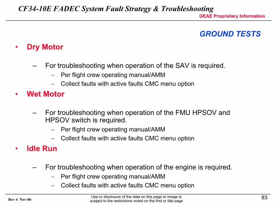
GROUND TESTS• Dry Motor
– For troubleshooting when operation of the SAV is required.− Per flight crew operating manual/AMM− Collect faults with active faults CMC menu option
• Wet Motor
– For troubleshooting when operation of the FMU HPSOV and HPSOV switch is required.− Per flight crew operating manual/AMM− Collect faults with active faults CMC menu option
• Idle Run
– For troubleshooting when operation of the engine is required.− Per flight crew operating manual/AMM− Collect faults with active faults CMC menu option
CF34-10E FADEC System Fault Strategy & TroubleshootingGEAE Proprietary Information
Use or disclosure of the data on this page or image is subject to the restrictions noted on the first or title page
84Rev 4 Nov-06
Overspeed Protection
CF34-10E FADEC System Fault Strategy & TroubleshootingGEAE Proprietary Information
Use or disclosure of the data on this page or image is subject to the restrictions noted on the first or title page
85Rev 4 Nov-06
Overspeed Protection
• Overspeed protection is provided on the core rotor speed, i.e. the fan will not overspeed unless the core rotor overspeeds first
• When an overspeed condition is detected, N2 > 100.95% (18190 RPM)– The fuel shut-of solenoid in the FMU closes– Fuel is shut off and the engine flames out– The FADEC will detect the flameout and turn on ignition– When speed falls below the overspeed threshold, the shut off solenoid
will be de-energized and fuel will be turned back on– Engine recovery is expected
• The overspeed system latches fuel off if three or more overspeedconditions are detected within 30 seconds
• Normal fuel operation resumes when the pilot commands and engineshutdown via the STOP switch.
CF34-10E FADEC System Fault Strategy & TroubleshootingGEAE Proprietary Information
Use or disclosure of the data on this page or image is subject to the restrictions noted on the first or title page
86Rev 4 Nov-06
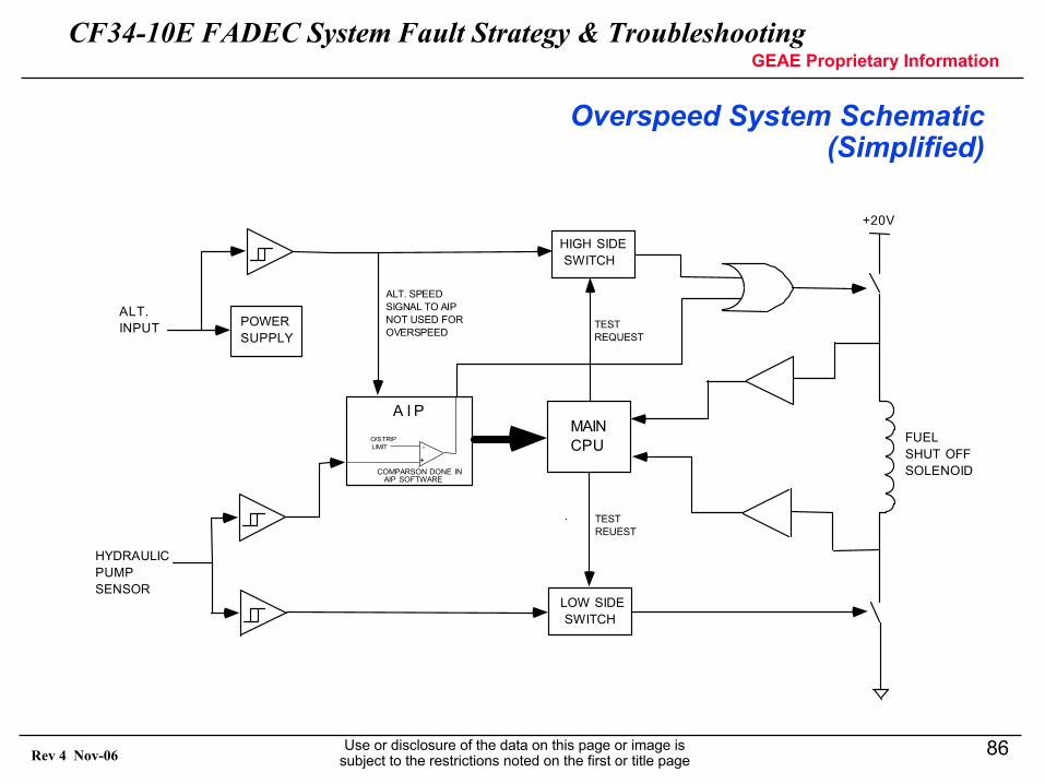
Overspeed System Schematic (Simplified)
POWERSUPPLY
ALT.INPUT
HYDRAULICPUMPSENSOR
O/S TRIP LIMIT
HIGH SIDE SWITCH
LOW SIDE SWITCH
+
-
COMPARSON DONE IN AIP SOFTWARE
A I PMAINCPU
ALT. SPEEDSIGNAL TO AIPNOT USED FOROVERSPEED
TESTREQUEST
TESTREUEST
+20V
FUELSHUT OFFSOLENOID
CF34-10E FADEC System Fault Strategy & TroubleshootingGEAE Proprietary Information
Use or disclosure of the data on this page or image is subject to the restrictions noted on the first or title page
87Rev 4 Nov-06
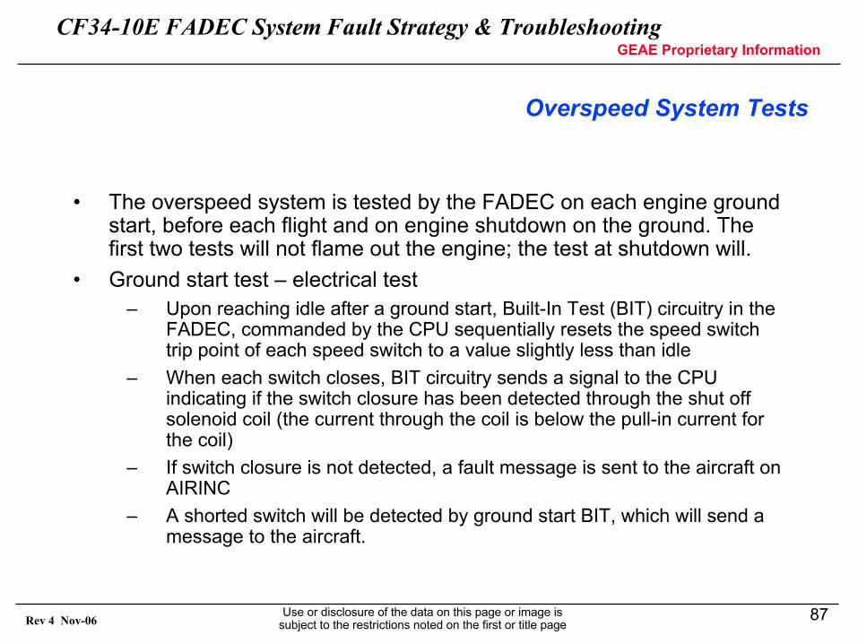
Overspeed System Tests
• The overspeed system is tested by the FADEC on each engine ground start, before each flight and on engine shutdown on the ground. The first two tests will not flame out the engine; the test at shutdown will.
• Ground start test – electrical test– Upon reaching idle after a ground start, Built-In Test (BIT) circuitry in the
FADEC, commanded by the CPU sequentially resets the speed switchtrip point of each speed switch to a value slightly less than idle
– When each switch closes, BIT circuitry sends a signal to the CPUindicating if the switch closure has been detected through the shut off solenoid coil (the current through the coil is below the pull-in current for the coil)
– If switch closure is not detected, a fault message is sent to the aircraft on AIRINC
– A shorted switch will be detected by ground start BIT, which will send a message to the aircraft.
CF34-10E FADEC System Fault Strategy & TroubleshootingGEAE Proprietary Information
Use or disclosure of the data on this page or image is subject to the restrictions noted on the first or title page
88Rev 4 Nov-06
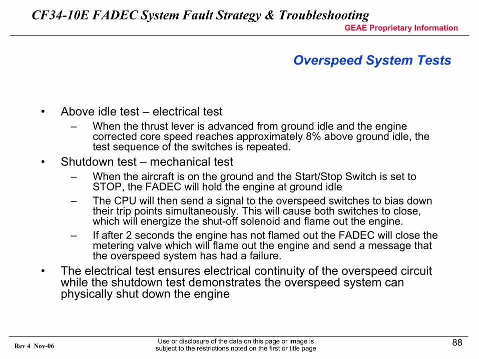
Overspeed System Tests
• Above idle test – electrical test– When the thrust lever is advanced from ground idle and the engine
corrected core speed reaches approximately 8% above ground idle, the test sequence of the switches is repeated.
• Shutdown test – mechanical test– When the aircraft is on the ground and the Start/Stop Switch is set to
STOP, the FADEC will hold the engine at ground idle– The CPU will then send a signal to the overspeed switches to bias down
their trip points simultaneously. This will cause both switches to close, which will energize the shut-off solenoid and flame out the engine.
– If after 2 seconds the engine has not flamed out the FADEC will close the metering valve which will flame out the engine and send a message that the overspeed system has had a failure.
• The electrical test ensures electrical continuity of the overspeed circuit while the shutdown test demonstrates the overspeed system can physically shut down the engine
CF34-10E FADEC System Fault Strategy & TroubleshootingGEAE Proprietary Information
Use or disclosure of the data on this page or image is subject to the restrictions noted on the first or title page
89Rev 4 Nov-06
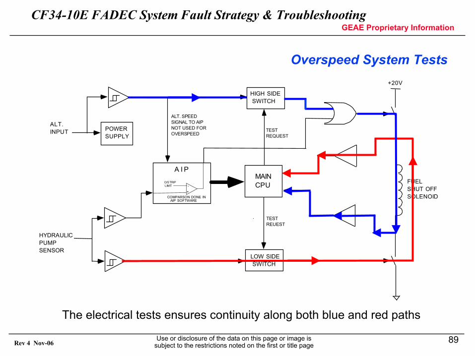
Overspeed System Tests
POWERSUPPLY
ALT.INPUT
HYDRAULICPUMPSENSOR
O/S TRIP LIMIT
HIGH SIDE SWITCH
LOW SIDE SWITCH
+
-
COMPARSON DONE IN AIP SOFTWARE
A I PMAINCPU
ALT. SPEEDSIGNAL TO AIPNOT USED FOROVERSPEED
TESTREQUEST
TESTREUEST
+20V
FUELSHUT OFFSOLENOID
The electrical tests ensures continuity along both blue and red paths
CF34-10E FADEC System Fault Strategy & TroubleshootingGEAE Proprietary Information
Use or disclosure of the data on this page or image is subject to the restrictions noted on the first or title page
90Rev 4 Nov-06
Overspeed System Tests
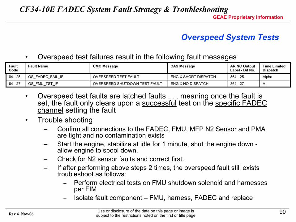
• Overspeed test failures result in the following fault messages
• Overspeed test faults are latched faults . . . meaning once the fault is set, the fault only clears upon a successful test on the specific FADEC channel setting the fault
• Trouble shooting– Confirm all connections to the FADEC, FMU, MFP N2 Sensor and PMA
are tight and no contamination exists– Start the engine, stabilize at idle for 1 minute, shut the engine down -
allow engine to spool down.– Check for N2 sensor faults and correct first.– If after performing above steps 2 times, the overspeed fault still exists
troubleshoot as follows:− Perform electrical tests on FMU shutdown solenoid and harnesses
per FIM− Isolate fault component – FMU, harness, FADEC and replace
A364 - 27ENG X NO DISPATCHOVERSPEED SHUTDOWN TEST FAULTOS_FMU_TST_IF64 - 27
Alpha364 - 25ENG X SHORT DISPATCHOVERSPEED TEST FAULTOS_FADEC_FAIL_IF64 - 25
Time Limited Dispatch
ARINC Output Label - Bit No.
CAS MessageCMC MessageFault NameFault Code
CF34-10E FADEC System Fault Strategy & TroubleshootingGEAE Proprietary Information
Use or disclosure of the data on this page or image is subject to the restrictions noted on the first or title page
91Rev 4 Nov-06
Engine Manuals
CF34-10E FADEC System Fault Strategy & TroubleshootingGEAE Proprietary Information
Use or disclosure of the data on this page or image is subject to the restrictions noted on the first or title page
92Rev 4 Nov-06
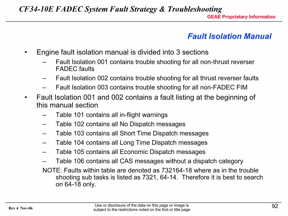
Fault Isolation Manual
• Engine fault isolation manual is divided into 3 sections– Fault Isolation 001 contains trouble shooting for all non-thrust reverser
FADEC faults– Fault Isolation 002 contains trouble shooting for all thrust reverser faults– Fault Isolation 003 contains trouble shooting for all non-FADEC FIM
• Fault Isolation 001 and 002 contains a fault listing at the beginning of this manual section
– Table 101 contains all in-flight warnings– Table 102 contains all No Dispatch messages– Table 103 contains all Short Time Dispatch messages– Table 104 contains all Long Time Dispatch messages– Table 105 contains all Economic Dispatch messages– Table 106 contains all CAS messages without a dispatch categoryNOTE: Faults within table are denoted as 732164-18 where as in the trouble
shooting sub tasks is listed as 7321, 64-14. Therefore it is best to search on 64-18 only.
CF34-10E FADEC System Fault Strategy & TroubleshootingGEAE Proprietary Information
Use or disclosure of the data on this page or image is subject to the restrictions noted on the first or title page
93Rev 4 Nov-06
Fault Isolation Manual
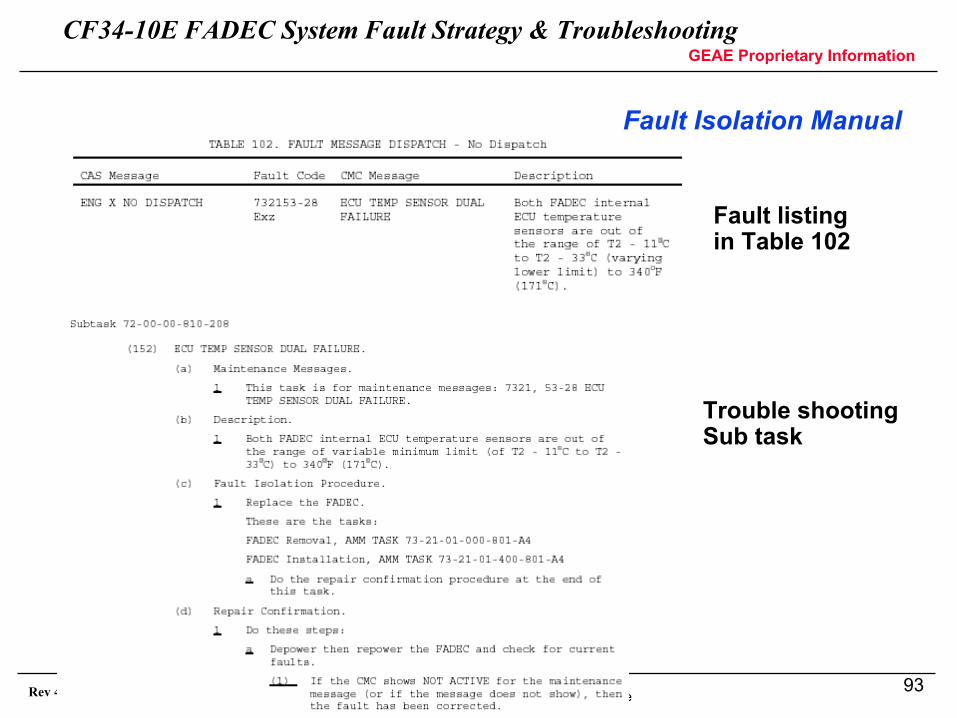
Fault listing in Table 102
Trouble shootingSub task
CF34-10E FADEC System Fault Strategy & TroubleshootingGEAE Proprietary Information
Use or disclosure of the data on this page or image is subject to the restrictions noted on the first or title page
94Rev 4 Nov-06
Non-FADEC Fault Isolation Manual
• Fault Isolation 003 contains all trouble shooting for engine anomalies not associated with a FADEC fault message
• The following is a list of non FADEC FIM tasks– Engine Auto Accel– Engine Auto Decel or Thrust Loss– Bird Strike– ITT Redline Exceedance– Engine Has Slow Response to Thrust Lever Movement– N1 Redline Exceedance– N2 Redline Exceedance– Engine Oil Consumption High or Low Oil Quantity– Engine Drain Mast Fuel or Oil Leakage– Power Fluctuates– Engine is the Cause of Oil/Fuel Fumes/Smoke in the cabin– Engine Stall– Mismatched Fuel Flow, N2 and ITT Indications with Engine Power (N1)
Matched
CF34-10E FADEC System Fault Strategy & TroubleshootingGEAE Proprietary Information
Use or disclosure of the data on this page or image is subject to the restrictions noted on the first or title page
95Rev 4 Nov-06
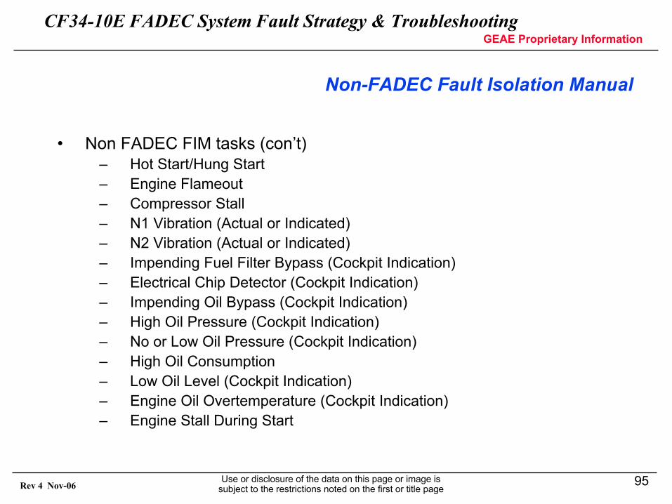
Non-FADEC Fault Isolation Manual
• Non FADEC FIM tasks (con’t)– Hot Start/Hung Start– Engine Flameout– Compressor Stall– N1 Vibration (Actual or Indicated)– N2 Vibration (Actual or Indicated)– Impending Fuel Filter Bypass (Cockpit Indication)– Electrical Chip Detector (Cockpit Indication)– Impending Oil Bypass (Cockpit Indication)– High Oil Pressure (Cockpit Indication)– No or Low Oil Pressure (Cockpit Indication)– High Oil Consumption– Low Oil Level (Cockpit Indication)– Engine Oil Overtemperature (Cockpit Indication)– Engine Stall During Start
CF34-10E FADEC System Fault Strategy & TroubleshootingGEAE Proprietary Information
Use or disclosure of the data on this page or image is subject to the restrictions noted on the first or title page
96Rev 4 Nov-06
ITT Exceedances and the ITT Overlimit Table
CF34-10E FADEC System Fault Strategy & TroubleshootingGEAE Proprietary Information
Use or disclosure of the data on this page or image is subject to the restrictions noted on the first or title page
97Rev 4 Nov-06
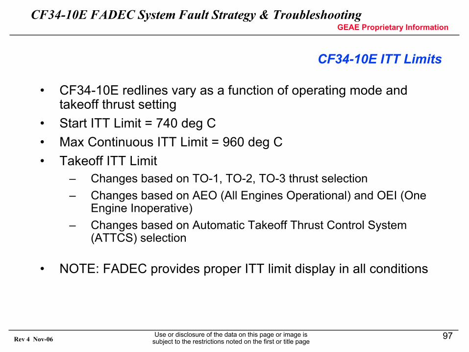
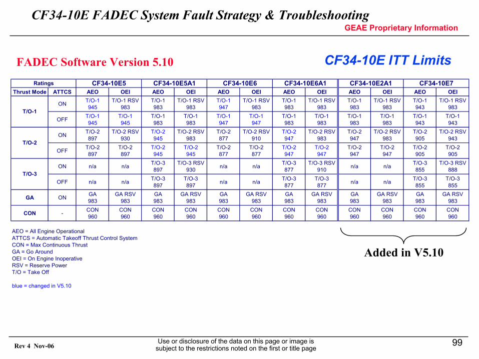
CF34-10E ITT Limits
• CF34-10E redlines vary as a function of operating mode and takeoff thrust setting
• Start ITT Limit = 740 deg C• Max Continuous ITT Limit = 960 deg C• Takeoff ITT Limit
– Changes based on TO-1, TO-2, TO-3 thrust selection– Changes based on AEO (All Engines Operational) and OEI (One
Engine Inoperative)– Changes based on Automatic Takeoff Thrust Control System
(ATTCS) selection
• NOTE: FADEC provides proper ITT limit display in all conditions
CF34-10E FADEC System Fault Strategy & TroubleshootingGEAE Proprietary Information
Use or disclosure of the data on this page or image is subject to the restrictions noted on the first or title page
98Rev 4 Nov-06
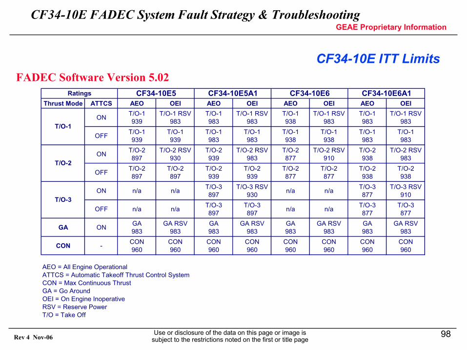
CF34-10E ITT LimitsFADEC Software Version 5.02
Thrust Mode ATTCS AEO OEI AEO OEI AEO OEI AEO OEI
ON T/O-1939
T/O-1 RSV983
T/O-1983
T/O-1 RSV983
T/O-1938
T/O-1 RSV983
T/O-1983
T/O-1 RSV983
OFF T/O-1939
T/O-1939
T/O-1983
T/O-1983
T/O-1938
T/O-1938
T/O-1983
T/O-1983
ON T/O-2897
T/O-2 RSV930
T/O-2939
T/O-2 RSV983
T/O-2877
T/O-2 RSV910
T/O-2938
T/O-2 RSV983
OFF T/O-2897
T/O-2897
T/O-2939
T/O-2939
T/O-2877
T/O-2877
T/O-2938
T/O-2938
ON n/a n/a T/O-3897
T/O-3 RSV930 n/a n/a T/O-3
877T/O-3 RSV
910
OFF n/a n/a T/O-3897
T/O-3897 n/a n/a T/O-3
877T/O-3877
GA ON GA983
GA RSV983
GA983
GA RSV983
GA983
GA RSV983
GA983
GA RSV983
CON - CON960
CON960
CON960
CON960
CON960
CON960
CON960
CON960
AEO = All Engine OperationalATTCS = Automatic Takeoff Thrust Control System CON = Max Continuous ThrustGA = Go AroundOEI = On Engine InoperativeRSV = Reserve PowerT/O = Take Off
CF34-10E6A1
T/O-1
CF34-10E5A1 CF34-10E6
T/O-2
T/O-3
CF34-10E5Ratings
CF34-10E FADEC System Fault Strategy & TroubleshootingGEAE Proprietary Information
Use or disclosure of the data on this page or image is subject to the restrictions noted on the first or title page
99Rev 4 Nov-06
CF34-10E ITT LimitsFADEC Software Version 5.10
Thrust Mode ATTCS AEO OEI AEO OEI AEO OEI AEO OEI AEO OEI AEO OEI
ON T/O-1945
T/O-1 RSV983
T/O-1983
T/O-1 RSV983
T/O-1947
T/O-1 RSV983
T/O-1983
T/O-1 RSV983
T/O-1983
T/O-1 RSV983
T/O-1943
T/O-1 RSV983
OFF T/O-1945
T/O-1945
T/O-1983
T/O-1983
T/O-1947
T/O-1947
T/O-1983
T/O-1983
T/O-1983
T/O-1983
T/O-1943
T/O-1943
ON T/O-2897
T/O-2 RSV930
T/O-2945
T/O-2 RSV983
T/O-2877
T/O-2 RSV910
T/O-2947
T/O-2 RSV983
T/O-2947
T/O-2 RSV983
T/O-2905
T/O-2 RSV943
OFF T/O-2897
T/O-2897
T/O-2945
T/O-2945
T/O-2877
T/O-2877
T/O-2947
T/O-2947
T/O-2947
T/O-2947
T/O-2905
T/O-2905
ON n/a n/a T/O-3897
T/O-3 RSV930 n/a n/a T/O-3
877T/O-3 RSV
910 n/a n/a T/O-3855
T/O-3 RSV888
OFF n/a n/a T/O-3897
T/O-3897 n/a n/a T/O-3
877T/O-3877 n/a n/a T/O-3
855T/O-3855
GA ON GA983
GA RSV983
GA983
GA RSV983
GA983
GA RSV983
GA983
GA RSV983
GA983
GA RSV983
GA983
GA RSV983
CON - CON960
CON960
CON960
CON960
CON960
CON960
CON960
CON960
CON960
CON960
CON960
CON960
AEO = All Engine OperationalATTCS = Automatic Takeoff Thrust Control System CON = Max Continuous ThrustGA = Go AroundOEI = On Engine InoperativeRSV = Reserve PowerT/O = Take Off
blue = changed in V5.10
T/O-3
CF34-10E2A1Ratings CF34-10E5 CF34-10E7CF34-10E6A1
T/O-1
T/O-2
CF34-10E5A1 CF34-10E6
Added in V5.10
CF34-10E FADEC System Fault Strategy & TroubleshootingGEAE Proprietary Information
Use or disclosure of the data on this page or image is subject to the restrictions noted on the first or title page
100Rev 4 Nov-06
CF34-10E ITT Limits
• ITT exceedance maintenance actions– Determine Max ITT and duration (time above ITT limit)– Determine flight phase where ITT exceedance occurred – Plot Max ITT and duration on appropriate figure for that phase– Determine what area the exceedance falls in: A, B, C, D– Look up the maintenance action required for area A, B, C or D
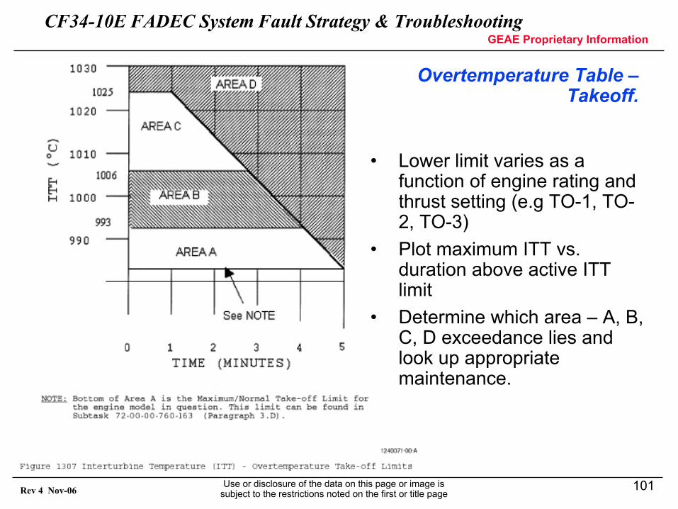
CF34-10E FADEC System Fault Strategy & TroubleshootingGEAE Proprietary Information
Use or disclosure of the data on this page or image is subject to the restrictions noted on the first or title page
101Rev 4 Nov-06
Overtemperature Table –Takeoff.
• Lower limit varies as a function of engine rating and thrust setting (e.g TO-1, TO-2, TO-3)
• Plot maximum ITT vs. duration above active ITT limit
• Determine which area – A, B, C, D exceedance lies and look up appropriate maintenance.
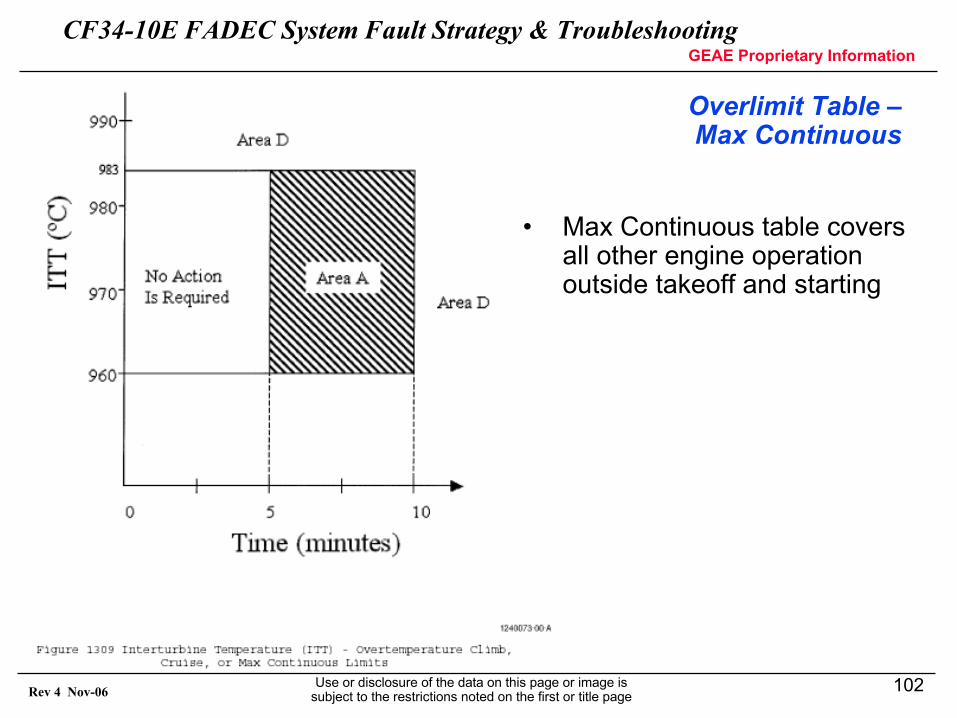
CF34-10E FADEC System Fault Strategy & TroubleshootingGEAE Proprietary Information
Use or disclosure of the data on this page or image is subject to the restrictions noted on the first or title page
102Rev 4 Nov-06
Overlimit Table –Max Continuous
• Max Continuous table covers all other engine operation outside takeoff and starting
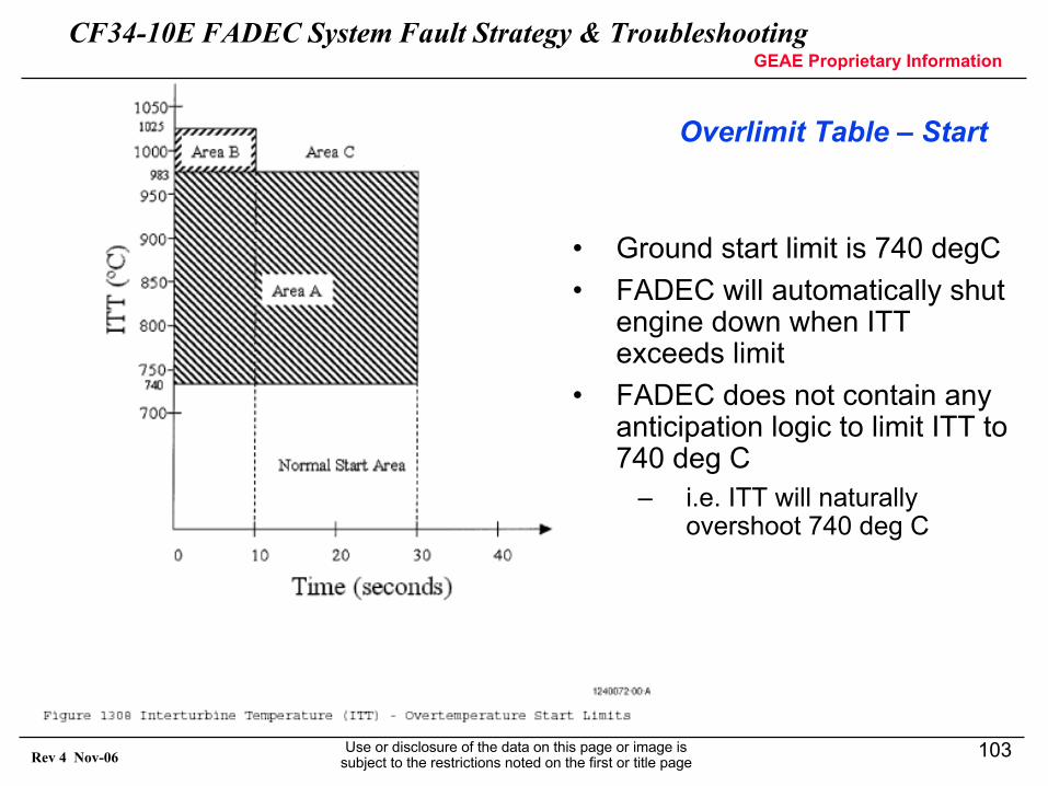
CF34-10E FADEC System Fault Strategy & TroubleshootingGEAE Proprietary Information
Use or disclosure of the data on this page or image is subject to the restrictions noted on the first or title page
103Rev 4 Nov-06
Overlimit Table – Start
• Ground start limit is 740 degC• FADEC will automatically shut
engine down when ITT exceeds limit
• FADEC does not contain any anticipation logic to limit ITT to 740 deg C
– i.e. ITT will naturally overshoot 740 deg C
CF34-10E FADEC System Fault Strategy & TroubleshootingGEAE Proprietary Information
Use or disclosure of the data on this page or image is subject to the restrictions noted on the first or title page
104Rev 4 Nov-06
Current Faults / Engine Issues
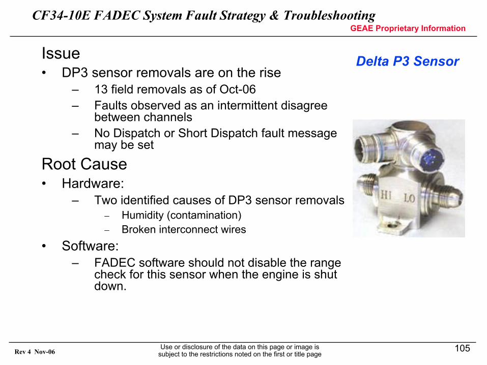
CF34-10E FADEC System Fault Strategy & TroubleshootingGEAE Proprietary Information
Use or disclosure of the data on this page or image is subject to the restrictions noted on the first or title page
105Rev 4 Nov-06
Delta P3 Sensor Issue• DP3 sensor removals are on the rise
– 13 field removals as of Oct-06– Faults observed as an intermittent disagree
between channels– No Dispatch or Short Dispatch fault message
may be set
Root Cause• Hardware:
– Two identified causes of DP3 sensor removals− Humidity (contamination)− Broken interconnect wires
• Software:– FADEC software should not disable the range
check for this sensor when the engine is shut down.
CF34-10E FADEC System Fault Strategy & TroubleshootingGEAE Proprietary Information
Use or disclosure of the data on this page or image is subject to the restrictions noted on the first or title page
106Rev 4 Nov-06
Delta P3 Sensor
Permanent Corrective Action• DP3 Sensor Hardware:
– Prevent broken internal wires & corrosion due to humidity– Modifications beginning Nov-06 to conformal coating of internal
sensing beam
• FADEC Software:– V5.10 incorporates short/long dispatch message
correction– V5.20 incorporates additional range checking
improvements.
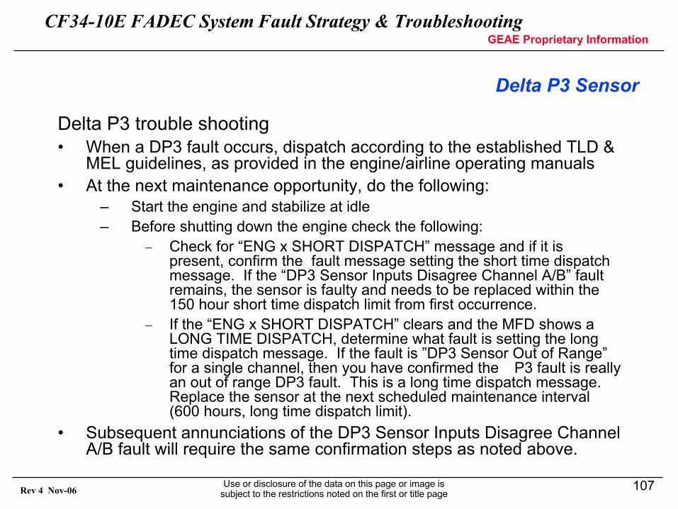
CF34-10E FADEC System Fault Strategy & TroubleshootingGEAE Proprietary Information
Use or disclosure of the data on this page or image is subject to the restrictions noted on the first or title page
107Rev 4 Nov-06
Delta P3 Sensor
Delta P3 trouble shooting• When a DP3 fault occurs, dispatch according to the established TLD &
MEL guidelines, as provided in the engine/airline operating manuals• At the next maintenance opportunity, do the following:
– Start the engine and stabilize at idle– Before shutting down the engine check the following:
− Check for “ENG x SHORT DISPATCH” message and if it is present, confirm the fault message setting the short time dispatch message. If the “DP3 Sensor Inputs Disagree Channel A/B” fault remains, the sensor is faulty and needs to be replaced within the 150 hour short time dispatch limit from first occurrence.
− If the “ENG x SHORT DISPATCH” clears and the MFD shows a LONG TIME DISPATCH, determine what fault is setting the long time dispatch message. If the fault is ”DP3 Sensor Out of Range” for a single channel, then you have confirmed the �P3 fault is really an out of range DP3 fault. This is a long time dispatch message. Replace the sensor at the next scheduled maintenance interval (600 hours, long time dispatch limit).
• Subsequent annunciations of the DP3 Sensor Inputs Disagree Channel A/B fault will require the same confirmation steps as noted above.
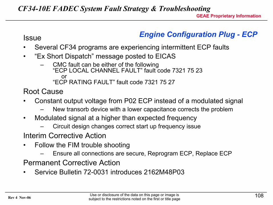
CF34-10E FADEC System Fault Strategy & TroubleshootingGEAE Proprietary Information
Use or disclosure of the data on this page or image is subject to the restrictions noted on the first or title page
108Rev 4 Nov-06
Engine Configuration Plug - ECPIssue• Several CF34 programs are experiencing intermittent ECP faults• “Ex Short Dispatch” message posted to EICAS
– CMC fault can be either of the following“ECP LOCAL CHANNEL FAULT” fault code 7321 75 23
or “ECP RATING FAULT” fault code 7321 75 27
Root Cause• Constant output voltage from P02 ECP instead of a modulated signal
– New transorb device with a lower capacitance corrects the problem• Modulated signal at a higher than expected frequency
– Circuit design changes correct start up frequency issueInterim Corrective Action• Follow the FIM trouble shooting
– Ensure all connections are secure, Reprogram ECP, Replace ECPPermanent Corrective Action• Service Bulletin 72-0031 introduces 2162M48P03
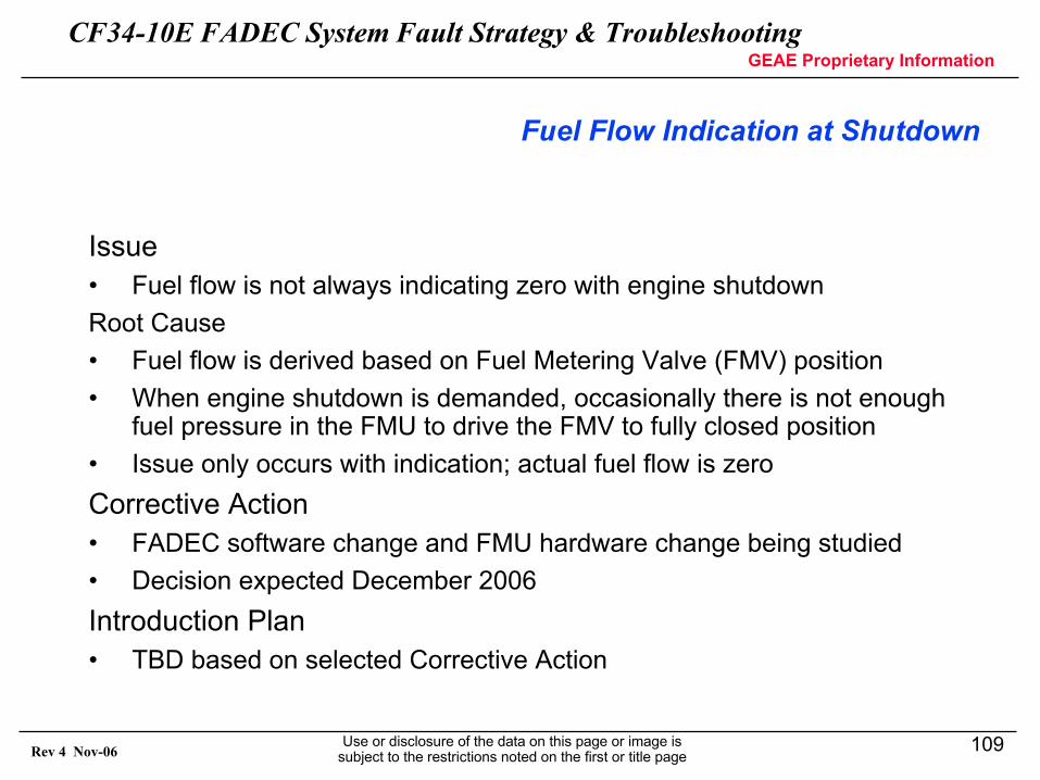
CF34-10E FADEC System Fault Strategy & TroubleshootingGEAE Proprietary Information
Use or disclosure of the data on this page or image is subject to the restrictions noted on the first or title page
109Rev 4 Nov-06
Fuel Flow Indication at Shutdown
Issue• Fuel flow is not always indicating zero with engine shutdownRoot Cause• Fuel flow is derived based on Fuel Metering Valve (FMV) position• When engine shutdown is demanded, occasionally there is not enough
fuel pressure in the FMU to drive the FMV to fully closed position• Issue only occurs with indication; actual fuel flow is zeroCorrective Action• FADEC software change and FMU hardware change being studied• Decision expected December 2006Introduction Plan• TBD based on selected Corrective Action
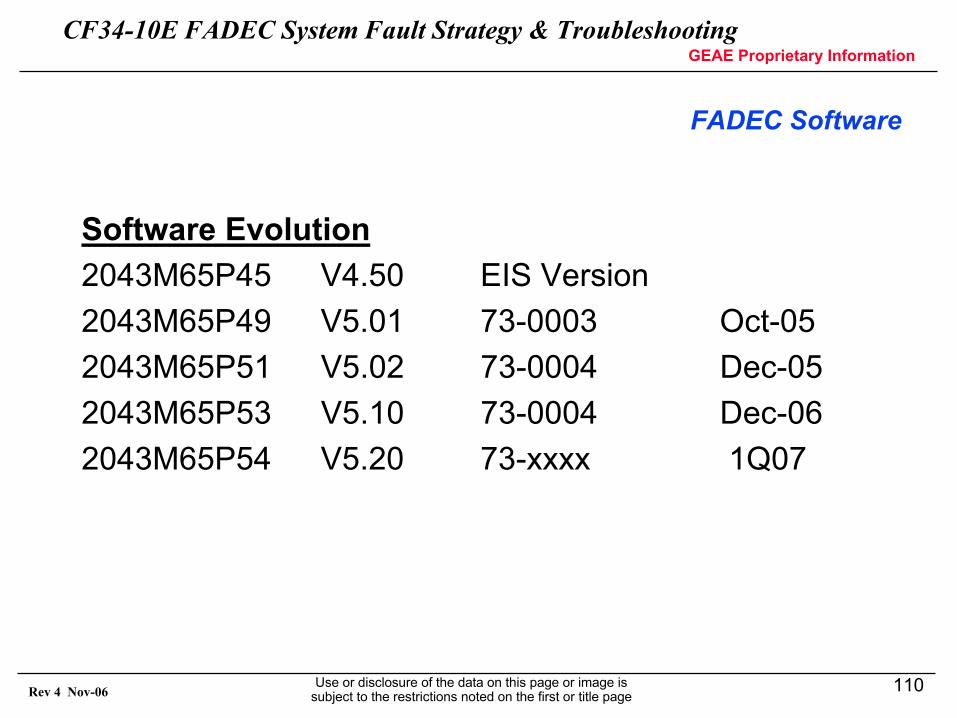
CF34-10E FADEC System Fault Strategy & TroubleshootingGEAE Proprietary Information
Use or disclosure of the data on this page or image is subject to the restrictions noted on the first or title page
110Rev 4 Nov-06
FADEC Software
Software Evolution2043M65P45 V4.50 EIS Version2043M65P49 V5.01 73-0003 Oct-052043M65P51 V5.02 73-0004 Dec-052043M65P53 V5.10 73-0004 Dec-062043M65P54 V5.20 73-xxxx 1Q07
CF34-10E FADEC System Fault Strategy & TroubleshootingGEAE Proprietary Information
Use or disclosure of the data on this page or image is subject to the restrictions noted on the first or title page
111Rev 4 Nov-06
FADEC Software
V5.02 Released Dec 29, 2005• N2 vibration start limit is extended from 10 seconds after idle to 60
seconds after idle while the throttle is at idle to avoid N2 vibration exceedances due to bowed rotor starts.
• Increased N2 vibration limits below 80 percent core speed and reduced N2 vibration limits above 80 percent core speeds.
– NOTE: The aircraft display and exceedance limits of 4.0 aircraft units will not change. The FADEC incorporates this change as a function of the measured values.
• Introduction of a lower minimum oil pressure limit during cold soak conditions and while the throttle is at idle for 2 minutes after engine start to avoid nuisance low oil pressure exceedance messages.
• Correct cockpit indications during takeoff when APR is activatedand a throttle split is present.
CF34-10E FADEC System Fault Strategy & TroubleshootingGEAE Proprietary Information
Use or disclosure of the data on this page or image is subject to the restrictions noted on the first or title page
112Rev 4 Nov-06
FADEC SoftwareV5.10 Planned Release December 2006• Includes CF34-10E2A1/10E7 power management and rating logic• Eliminates “Eng Exceedance” cockpit annunciation for N1 and N2
vibration• Improved fault annunciation for actuator faults that health reduction
– Corrects dispatch annunciation for dual VBV position fault– Eliminates spurious engine faults on shutdown (e.g. DP3)
• Improve cockpit indication of TR stowed position– Clearing action for current AD
• Optimized HPTACC logic changes to improve engine fuel burn• Increased ITT limits for CF34-10E5/10E5A1/10E6/10E6A1 engine
ratings
NOTE: FADEC software v5.20 will be available 1Q ’07> Required for Block 2 engines
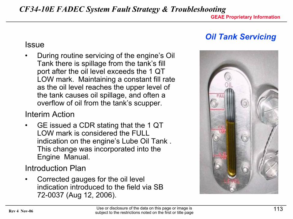
CF34-10E FADEC System Fault Strategy & TroubleshootingGEAE Proprietary Information
Use or disclosure of the data on this page or image is subject to the restrictions noted on the first or title page
113Rev 4 Nov-06
Oil Tank ServicingIssue• During routine servicing of the engine’s Oil
Tank there is spillage from the tank’s fill port after the oil level exceeds the 1 QT LOW mark. Maintaining a constant fill rate as the oil level reaches the upper level of the tank causes oil spillage, and often a overflow of oil from the tank’s scupper.
Interim Action• GE issued a CDR stating that the 1 QT
LOW mark is considered the FULL indication on the engine’s Lube Oil Tank . This change was incorporated into the Engine Manual.
Introduction Plan• Corrected gauges for the oil level
indication introduced to the field via SB 72-0037 (Aug 12, 2006).
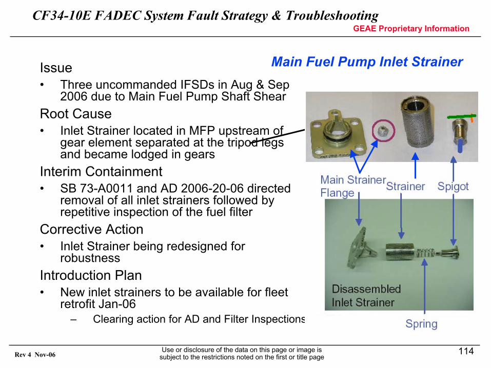
CF34-10E FADEC System Fault Strategy & TroubleshootingGEAE Proprietary Information
Use or disclosure of the data on this page or image is subject to the restrictions noted on the first or title page
114Rev 4 Nov-06
Main Fuel Pump Inlet StrainerIssue• Three uncommanded IFSDs in Aug & Sep
2006 due to Main Fuel Pump Shaft Shear Root Cause• Inlet Strainer located in MFP upstream of
gear element separated at the tripod legs and became lodged in gears
Interim Containment• SB 73-A0011 and AD 2006-20-06 directed
removal of all inlet strainers followed by repetitive inspection of the fuel filter
Corrective Action• Inlet Strainer being redesigned for
robustnessIntroduction Plan• New inlet strainers to be available for fleet
retrofit Jan-06– Clearing action for AD and Filter Inspections
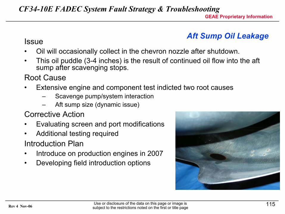
CF34-10E FADEC System Fault Strategy & TroubleshootingGEAE Proprietary Information
Use or disclosure of the data on this page or image is subject to the restrictions noted on the first or title page
115Rev 4 Nov-06
Aft Sump Oil LeakageIssue• Oil will occasionally collect in the chevron nozzle after shutdown. • This oil puddle (3-4 inches) is the result of continued oil flow into the aft
sump after scavenging stops. Root Cause• Extensive engine and component test indicted two root causes
– Scavenge pump/system interaction– Aft sump size (dynamic issue)
Corrective Action• Evaluating screen and port modifications• Additional testing required Introduction Plan• Introduce on production engines in 2007• Developing field introduction options
CF34-10E FADEC System Fault Strategy & TroubleshootingGEAE Proprietary Information
Use or disclosure of the data on this page or image is subject to the restrictions noted on the first or title page
116Rev 4 Nov-06
ECP Programming
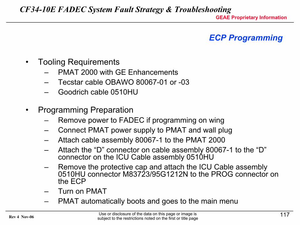
CF34-10E FADEC System Fault Strategy & TroubleshootingGEAE Proprietary Information
Use or disclosure of the data on this page or image is subject to the restrictions noted on the first or title page
117Rev 4 Nov-06
ECP Programming
• Tooling Requirements– PMAT 2000 with GE Enhancements– Tecstar cable OBAWO 80067-01 or -03– Goodrich cable 0510HU
• Programming Preparation– Remove power to FADEC if programming on wing– Connect PMAT power supply to PMAT and wall plug– Attach cable assembly 80067-1 to the PMAT 2000– Attach the “D” connector on cable assembly 80067-1 to the “D”
connector on the ICU Cable assembly 0510HU– Remove the protective cap and attach the ICU Cable assembly
0510HU connector M83723/95G1212N to the PROG connector on the ECP
– Turn on PMAT – PMAT automatically boots and goes to the main menu
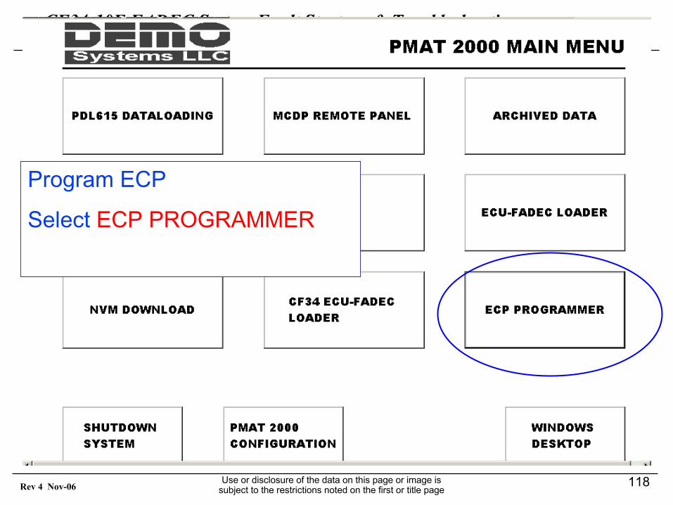
CF34-10E FADEC System Fault Strategy & TroubleshootingGEAE Proprietary Information
Use or disclosure of the data on this page or image is subject to the restrictions noted on the first or title page
118Rev 4 Nov-06
Program ECP
Select ECP PROGRAMMER
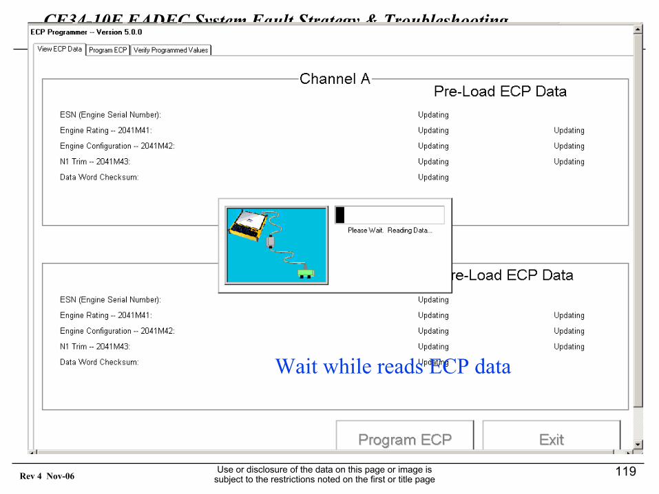
CF34-10E FADEC System Fault Strategy & TroubleshootingGEAE Proprietary Information
Use or disclosure of the data on this page or image is subject to the restrictions noted on the first or title page
119Rev 4 Nov-06
Wait while reads ECP data
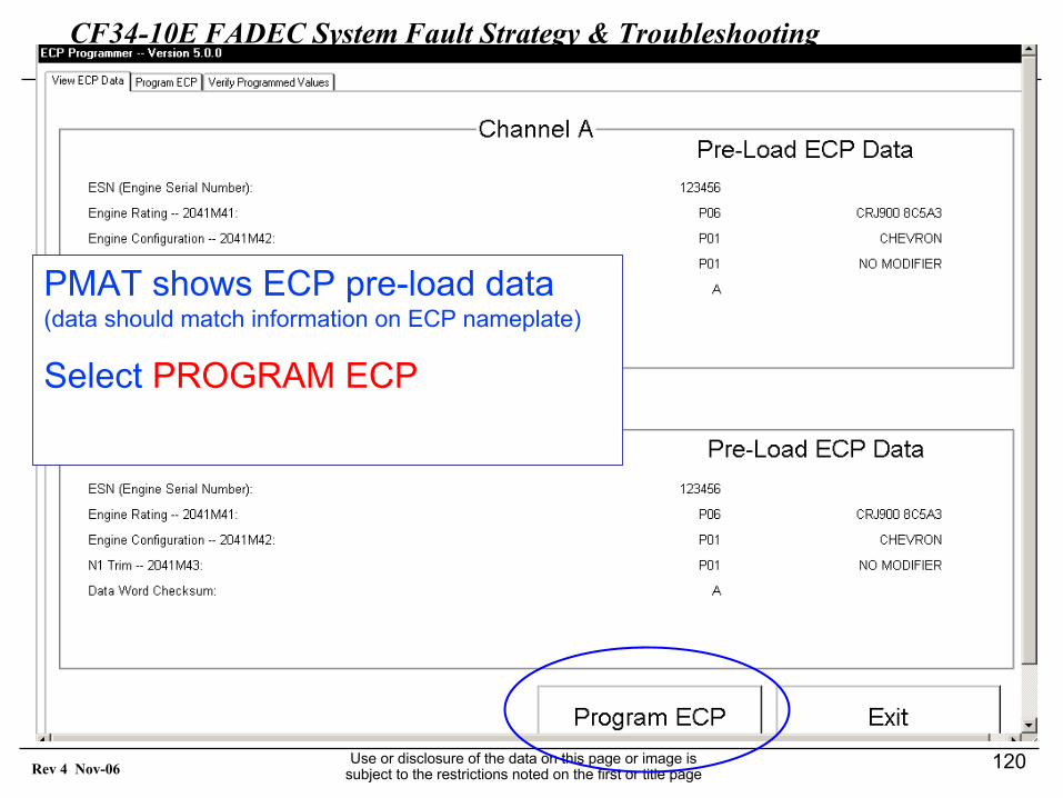
CF34-10E FADEC System Fault Strategy & TroubleshootingGEAE Proprietary Information
Use or disclosure of the data on this page or image is subject to the restrictions noted on the first or title page
120Rev 4 Nov-06
PMAT shows ECP pre-load data(data should match information on ECP nameplate)
Select PROGRAM ECP
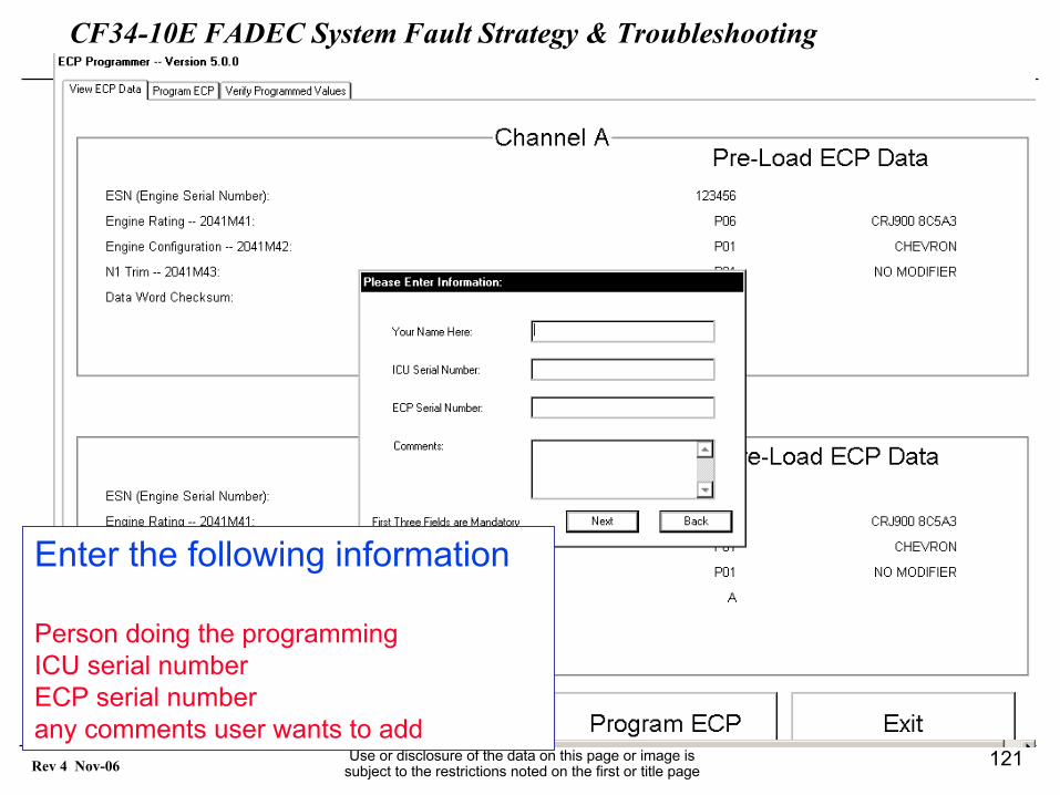
CF34-10E FADEC System Fault Strategy & TroubleshootingGEAE Proprietary Information
Use or disclosure of the data on this page or image is subject to the restrictions noted on the first or title page
121Rev 4 Nov-06
Enter the following information
Person doing the programmingICU serial numberECP serial numberany comments user wants to add
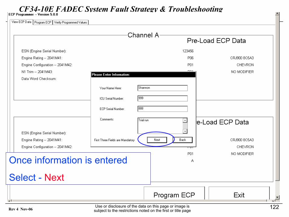
CF34-10E FADEC System Fault Strategy & TroubleshootingGEAE Proprietary Information
Use or disclosure of the data on this page or image is subject to the restrictions noted on the first or title page
122Rev 4 Nov-06
Once information is entered
Select - Next
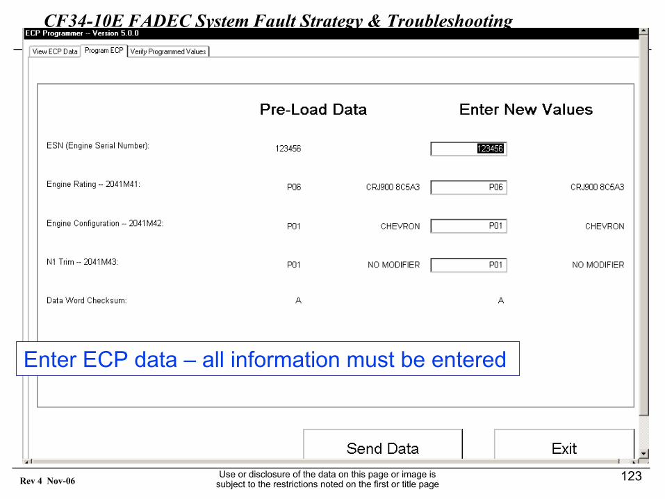
CF34-10E FADEC System Fault Strategy & TroubleshootingGEAE Proprietary Information
Use or disclosure of the data on this page or image is subject to the restrictions noted on the first or title page
123Rev 4 Nov-06
Enter ECP data – all information must be entered
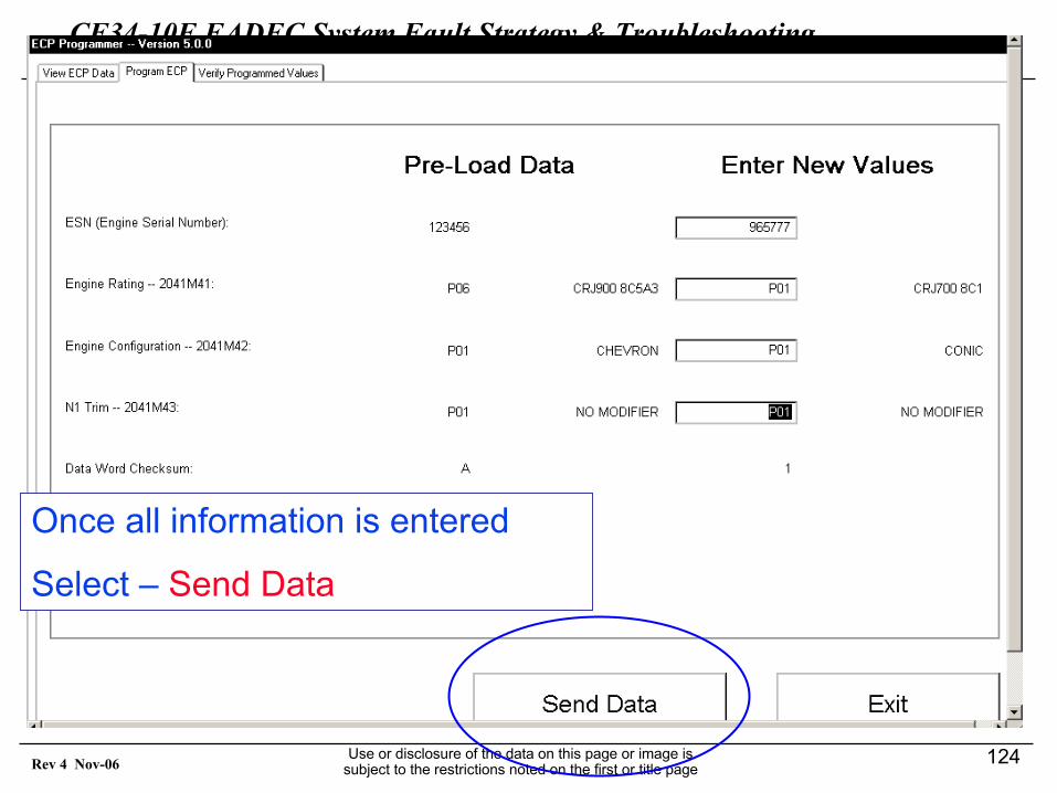
CF34-10E FADEC System Fault Strategy & TroubleshootingGEAE Proprietary Information
Use or disclosure of the data on this page or image is subject to the restrictions noted on the first or title page
124Rev 4 Nov-06
Once all information is entered
Select – Send Data
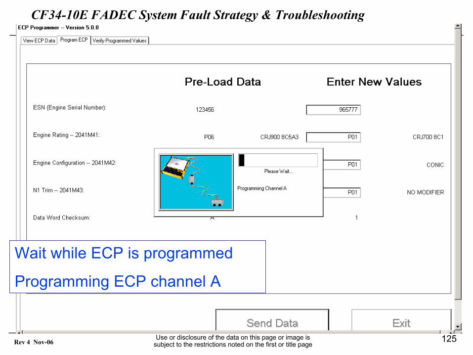
CF34-10E FADEC System Fault Strategy & TroubleshootingGEAE Proprietary Information
Use or disclosure of the data on this page or image is subject to the restrictions noted on the first or title page
125Rev 4 Nov-06
Wait while ECP is programmed
Programming ECP channel A
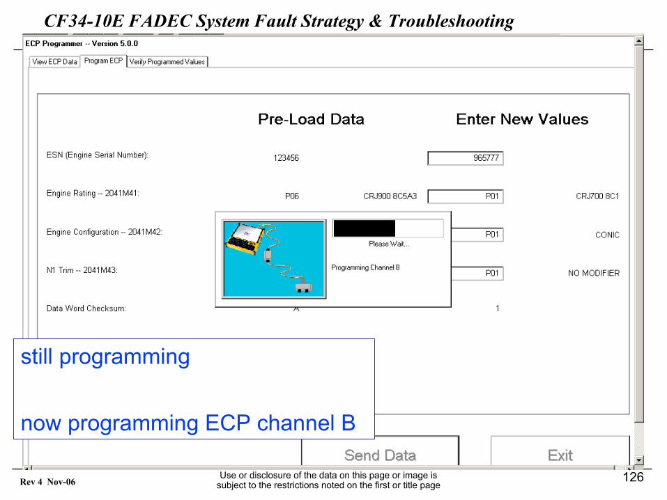
CF34-10E FADEC System Fault Strategy & TroubleshootingGEAE Proprietary Information
Use or disclosure of the data on this page or image is subject to the restrictions noted on the first or title page
126Rev 4 Nov-06
still programming
now programming ECP channel B
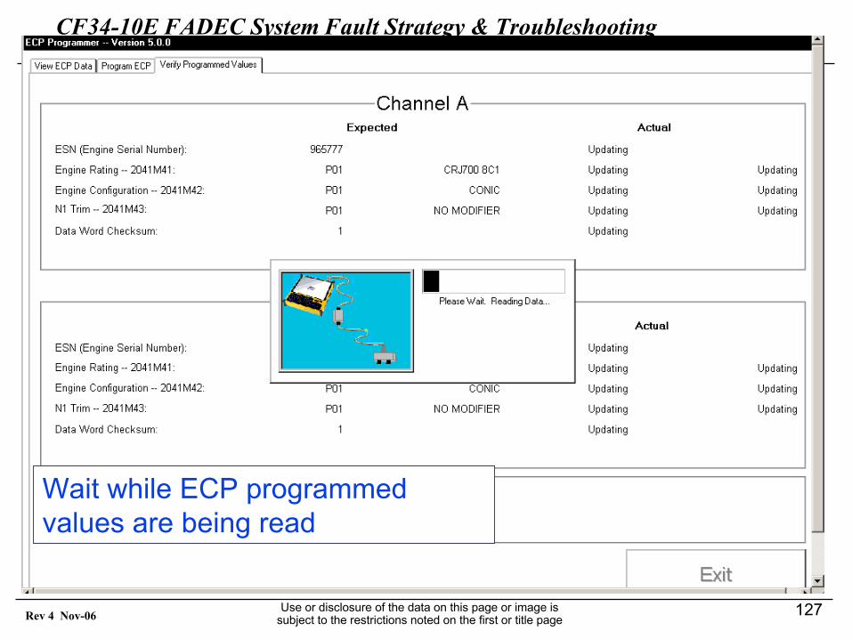
CF34-10E FADEC System Fault Strategy & TroubleshootingGEAE Proprietary Information
Use or disclosure of the data on this page or image is subject to the restrictions noted on the first or title page
127Rev 4 Nov-06
Wait while ECP programmed values are being read
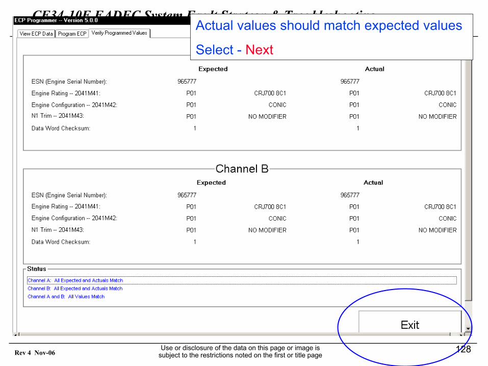
CF34-10E FADEC System Fault Strategy & TroubleshootingGEAE Proprietary Information
Use or disclosure of the data on this page or image is subject to the restrictions noted on the first or title page
128Rev 4 Nov-06
Actual values should match expected values
Select - Next
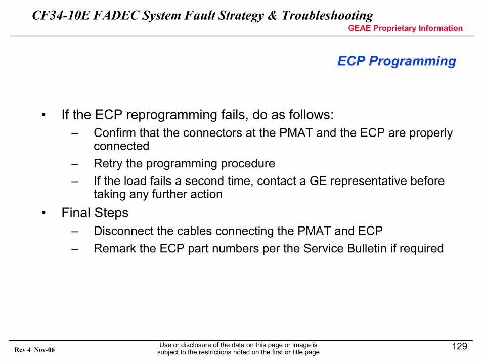
CF34-10E FADEC System Fault Strategy & TroubleshootingGEAE Proprietary Information
Use or disclosure of the data on this page or image is subject to the restrictions noted on the first or title page
129Rev 4 Nov-06
ECP Programming
• If the ECP reprogramming fails, do as follows:– Confirm that the connectors at the PMAT and the ECP are properly
connected– Retry the programming procedure – If the load fails a second time, contact a GE representative before
taking any further action• Final Steps
– Disconnect the cables connecting the PMAT and ECP– Remark the ECP part numbers per the Service Bulletin if required
CF34-10E FADEC System Fault Strategy & TroubleshootingGEAE Proprietary Information
Use or disclosure of the data on this page or image is subject to the restrictions noted on the first or title page
130Rev 4 Nov-06
Appendix A –Fault Messages and dispatch Level
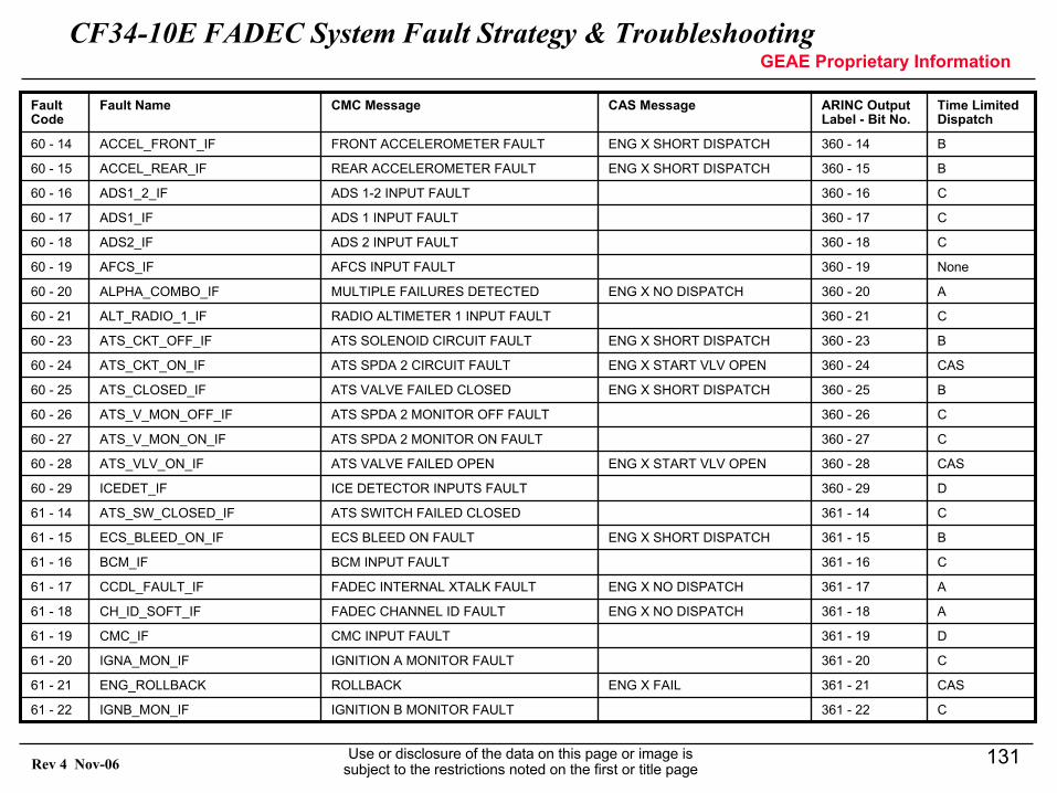
CF34-10E FADEC System Fault Strategy & TroubleshootingGEAE Proprietary Information
Use or disclosure of the data on this page or image is subject to the restrictions noted on the first or title page
131Rev 4 Nov-06
C361 - 22IGNITION B MONITOR FAULTIGNB_MON_IF61 - 22
CAS361 - 21ENG X FAILROLLBACKENG_ROLLBACK61 - 21
C361 - 20IGNITION A MONITOR FAULTIGNA_MON_IF61 - 20
D361 - 19CMC INPUT FAULTCMC_IF61 - 19
A361 - 18ENG X NO DISPATCHFADEC CHANNEL ID FAULTCH_ID_SOFT_IF61 - 18
A361 - 17ENG X NO DISPATCHFADEC INTERNAL XTALK FAULTCCDL_FAULT_IF61 - 17
C361 - 16BCM INPUT FAULTBCM_IF61 - 16
B361 - 15ENG X SHORT DISPATCHECS BLEED ON FAULTECS_BLEED_ON_IF61 - 15
C361 - 14ATS SWITCH FAILED CLOSEDATS_SW_CLOSED_IF61 - 14
D360 - 29ICE DETECTOR INPUTS FAULTICEDET_IF60 - 29
CAS360 - 28ENG X START VLV OPENATS VALVE FAILED OPENATS_VLV_ON_IF60 - 28
C360 - 27ATS SPDA 2 MONITOR ON FAULTATS_V_MON_ON_IF60 - 27
C360 - 26ATS SPDA 2 MONITOR OFF FAULTATS_V_MON_OFF_IF60 - 26
B360 - 25ENG X SHORT DISPATCHATS VALVE FAILED CLOSEDATS_CLOSED_IF60 - 25
CAS360 - 24ENG X START VLV OPENATS SPDA 2 CIRCUIT FAULTATS_CKT_ON_IF60 - 24
B360 - 23ENG X SHORT DISPATCHATS SOLENOID CIRCUIT FAULTATS_CKT_OFF_IF60 - 23
C360 - 21RADIO ALTIMETER 1 INPUT FAULTALT_RADIO_1_IF60 - 21
A360 - 20ENG X NO DISPATCHMULTIPLE FAILURES DETECTEDALPHA_COMBO_IF60 - 20
None360 - 19AFCS INPUT FAULTAFCS_IF60 - 19
C360 - 18ADS 2 INPUT FAULTADS2_IF60 - 18
C360 - 17ADS 1 INPUT FAULTADS1_IF60 - 17
C360 - 16ADS 1-2 INPUT FAULTADS1_2_IF60 - 16
B360 - 15ENG X SHORT DISPATCHREAR ACCELEROMETER FAULTACCEL_REAR_IF60 - 15
B360 - 14ENG X SHORT DISPATCHFRONT ACCELEROMETER FAULTACCEL_FRONT_IF60 - 14
Time Limited Dispatch
ARINC Output Label - Bit No.
CAS MessageCMC MessageFault NameFault Code
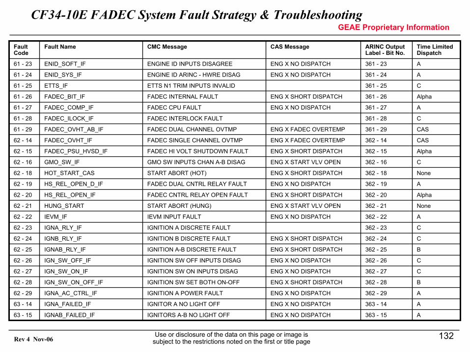
CF34-10E FADEC System Fault Strategy & TroubleshootingGEAE Proprietary Information
Use or disclosure of the data on this page or image is subject to the restrictions noted on the first or title page
132Rev 4 Nov-06
A363 - 15ENG X NO DISPATCHIGNITORS A-B NO LIGHT OFFIGNAB_FAILED_IF63 - 15
A363 - 14ENG X NO DISPATCHIGNITOR A NO LIGHT OFFIGNA_FAILED_IF63 - 14
A362 - 29ENG X NO DISPATCHIGNITION A POWER FAULTIGNA_AC_CTRL_IF62 - 29
B362 - 28ENG X SHORT DISPATCHIGNITION SW SET BOTH ON-OFFIGN_SW_ON_OFF_IF62 - 28
C362 - 27ENG X NO DISPATCHIGNITION SW ON INPUTS DISAGIGN_SW_ON_IF62 - 27
C362 - 26ENG X NO DISPATCHIGNITION SW OFF INPUTS DISAGIGN_SW_OFF_IF62 - 26
B362 - 25ENG X SHORT DISPATCHIGNITION A-B DISCRETE FAULTIGNAB_RLY_IF62 - 25
C362 - 24ENG X SHORT DISPATCHIGNITION B DISCRETE FAULTIGNB_RLY_IF62 - 24
C362 - 23IGNITION A DISCRETE FAULTIGNA_RLY_IF62 - 23
A362 - 22ENG X NO DISPATCHIEVM INPUT FAULTIEVM_IF62 - 22
None362 - 21ENG X START VLV OPENSTART ABORT (HUNG)HUNG_START62 - 21
Alpha362 - 20ENG X SHORT DISPATCHFADEC CNTRL RELAY OPEN FAULTHS_REL_OPEN_IF62 - 20
A362 - 19ENG X NO DISPATCHFADEC DUAL CNTRL RELAY FAULTHS_REL_OPEN_D_IF62 - 19
None362 - 18ENG X SHORT DISPATCHSTART ABORT (HOT)HOT_START_CAS62 - 18
C362 - 16ENG X START VLV OPENGMO SW INPUTS CHAN A-B DISAGGMO_SW_IF62 - 16
Alpha362 - 15ENG X SHORT DISPATCHFADEC HI VOLT SHUTDOWN FAULTFADEC_PSU_HVSD_IF62 - 15
CAS362 - 14ENG X FADEC OVERTEMPFADEC SINGLE CHANNEL OVTMPFADEC_OVHT_IF62 - 14
CAS361 - 29ENG X FADEC OVERTEMPFADEC DUAL CHANNEL OVTMPFADEC_OVHT_AB_IF61 - 29
C361 - 28FADEC INTERLOCK FAULTFADEC_ILOCK_IF61 - 28
A361 - 27ENG X NO DISPATCHFADEC CPU FAULTFADEC_COMP_IF61 - 27
Alpha361 - 26ENG X SHORT DISPATCHFADEC INTERNAL FAULTFADEC_BIT_IF61 - 26
C361 - 25ETTS N1 TRIM INPUTS INVALIDETTS_IF61 - 25
A361 - 24ENG X NO DISPATCHENGINE ID ARINC - HWRE DISAGENID_SYS_IF61 - 24
A361 - 23ENG X NO DISPATCHENGINE ID INPUTS DISAGREEENID_SOFT_IF61 - 23
Time Limited Dispatch
ARINC Output Label - Bit No.
CAS MessageCMC MessageFault NameFault Code
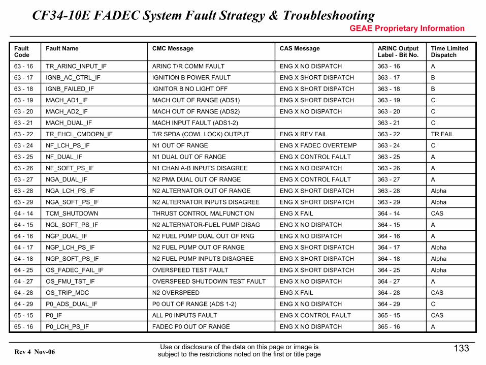
CF34-10E FADEC System Fault Strategy & TroubleshootingGEAE Proprietary Information
Use or disclosure of the data on this page or image is subject to the restrictions noted on the first or title page
133Rev 4 Nov-06
A365 - 16ENG X NO DISPATCHFADEC P0 OUT OF RANGEP0_LCH_PS_IF65 - 16
CAS365 - 15ENG X CONTROL FAULTALL P0 INPUTS FAULTP0_IF65 - 15
C364 - 29ENG X NO DISPATCHP0 OUT OF RANGE (ADS 1-2)P0_ADS_DUAL_IF64 - 29
CAS364 - 28ENG X FAILN2 OVERSPEEDOS_TRIP_MDC64 - 28
A364 - 27ENG X NO DISPATCHOVERSPEED SHUTDOWN TEST FAULTOS_FMU_TST_IF64 - 27
Alpha364 - 25ENG X SHORT DISPATCHOVERSPEED TEST FAULTOS_FADEC_FAIL_IF64 - 25
Alpha364 - 18ENG X SHORT DISPATCHN2 FUEL PUMP INPUTS DISAGREENGP_SOFT_PS_IF64 - 18
Alpha364 - 17ENG X SHORT DISPATCHN2 FUEL PUMP OUT OF RANGENGP_LCH_PS_IF64 - 17
A364 - 16ENG X NO DISPATCHN2 FUEL PUMP DUAL OUT OF RNGNGP_DUAL_IF64 - 16
A364 - 15ENG X NO DISPATCHN2 ALTERNATOR-FUEL PUMP DISAGNGL_SOFT_PS_IF64 - 15
CAS364 - 14ENG X FAILTHRUST CONTROL MALFUNCTIONTCM_SHUTDOWN64 - 14
Alpha363 - 29ENG X SHORT DISPATCHN2 ALTERNATOR INPUTS DISAGREENGA_SOFT_PS_IF63 - 29
Alpha363 - 28ENG X SHORT DISPATCHN2 ALTERNATOR OUT OF RANGENGA_LCH_PS_IF63 - 28
A363 - 27ENG X CONTROL FAULTN2 PMA DUAL OUT OF RANGENGA_DUAL_IF63 - 27
A363 - 26ENG X NO DISPATCHN1 CHAN A-B INPUTS DISAGREENF_SOFT_PS_IF63 - 26
A363 - 25ENG X CONTROL FAULTN1 DUAL OUT OF RANGENF_DUAL_IF63 - 25
C363 - 24ENG X FADEC OVERTEMPN1 OUT OF RANGENF_LCH_PS_IF63 - 24
TR FAIL363 - 22ENG X REV FAILT/R SPDA (COWL LOCK) OUTPUTTR_EHCL_CMDOPN_IF63 - 22
C363 - 21MACH INPUT FAULT (ADS1-2)MACH_DUAL_IF63 - 21
C363 - 20ENG X NO DISPATCHMACH OUT OF RANGE (ADS2)MACH_AD2_IF63 - 20
C363 - 19ENG X SHORT DISPATCHMACH OUT OF RANGE (ADS1)MACH_AD1_IF63 - 19
B363 - 18ENG X SHORT DISPATCHIGNITOR B NO LIGHT OFFIGNB_FAILED_IF63 - 18
B363 - 17ENG X SHORT DISPATCHIGNITION B POWER FAULTIGNB_AC_CTRL_IF63 - 17
A363 - 16ENG X NO DISPATCHARINC T/R COMM FAULTTR_ARINC_INPUT_IF63 - 16
Time Limited Dispatch
ARINC Output Label - Bit No.
CAS MessageCMC MessageFault NameFault Code
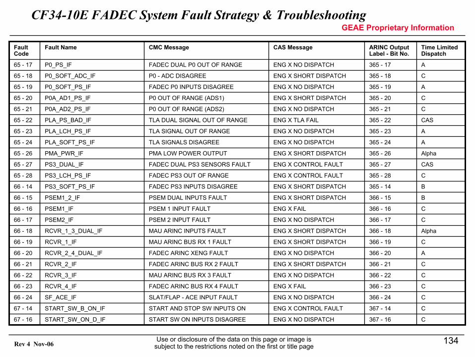
CF34-10E FADEC System Fault Strategy & TroubleshootingGEAE Proprietary Information
Use or disclosure of the data on this page or image is subject to the restrictions noted on the first or title page
134Rev 4 Nov-06
C367 - 16ENG X NO DISPATCHSTART SW ON INPUTS DISAGREESTART_SW_ON_D_IF67 - 16
C367 - 14ENG X CONTROL FAULTSTART AND STOP SW INPUTS ONSTART_SW_B_ON_IF67 - 14
C366 - 24ENG X NO DISPATCHSLAT/FLAP - ACE INPUT FAULTSF_ACE_IF66 - 24
C366 - 23ENG X FAILFADEC ARINC BUS RX 4 FAULTRCVR_4_IF66 - 23
C366 - 22ENG X NO DISPATCHMAU ARINC BUS RX 3 FAULTRCVR_3_IF66 - 22
C366 - 21ENG X SHORT DISPATCHFADEC ARINC BUS RX 2 FAULTRCVR_2_IF66 - 21
A366 - 20ENG X NO DISPATCHFADEC ARINC XENG FAULTRCVR_2_4_DUAL_IF66 - 20
C366 - 19ENG X SHORT DISPATCHMAU ARINC BUS RX 1 FAULTRCVR_1_IF66 - 19
Alpha366 - 18ENG X SHORT DISPATCHMAU ARINC INPUTS FAULTRCVR_1_3_DUAL_IF66 - 18
C366 - 17ENG X NO DISPATCHPSEM 2 INPUT FAULTPSEM2_IF66 - 17
C366 - 16ENG X FAILPSEM 1 INPUT FAULTPSEM1_IF66 - 16
B366 - 15ENG X SHORT DISPATCHPSEM DUAL INPUTS FAULTPSEM1_2_IF66 - 15
B365 - 14ENG X SHORT DISPATCHFADEC PS3 INPUTS DISAGREEPS3_SOFT_PS_IF66 - 14
C365 - 28ENG X CONTROL FAULTFADEC PS3 OUT OF RANGEPS3_LCH_PS_IF65 - 28
CAS365 - 27ENG X CONTROL FAULTFADEC DUAL PS3 SENSORS FAULTPS3_DUAL_IF65 - 27
Alpha365 - 26ENG X SHORT DISPATCHPMA LOW POWER OUTPUTPMA_PWR_IF65 - 26
A365 - 24ENG X NO DISPATCHTLA SIGNALS DISAGREEPLA_SOFT_PS_IF65 - 24
A365 - 23ENG X NO DISPATCHTLA SIGNAL OUT OF RANGEPLA_LCH_PS_IF65 - 23
CAS365 - 22ENG X TLA FAILTLA DUAL SIGNAL OUT OF RANGEPLA_PS_BAD_IF65 - 22
C365 - 21ENG X NO DISPATCHP0 OUT OF RANGE (ADS2)P0A_AD2_PS_IF65 - 21
C365 - 20ENG X SHORT DISPATCHP0 OUT OF RANGE (ADS1)P0A_AD1_PS_IF65 - 20
A365 - 19ENG X NO DISPATCHFADEC P0 INPUTS DISAGREEP0_SOFT_PS_IF65 - 19
C365 - 18ENG X SHORT DISPATCHP0 - ADC DISAGREEP0_SOFT_ADC_IF65 - 18
A365 - 17ENG X NO DISPATCHFADEC DUAL P0 OUT OF RANGEP0_PS_IF65 - 17
Time Limited Dispatch
ARINC Output Label - Bit No.
CAS MessageCMC MessageFault NameFault Code
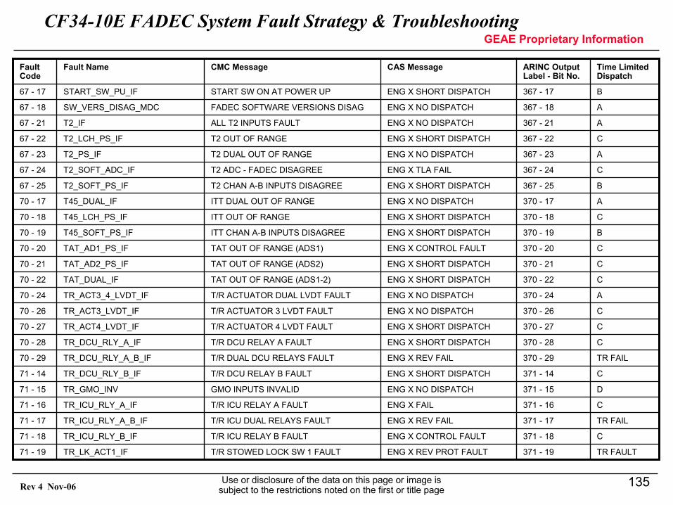
CF34-10E FADEC System Fault Strategy & TroubleshootingGEAE Proprietary Information
Use or disclosure of the data on this page or image is subject to the restrictions noted on the first or title page
135Rev 4 Nov-06
TR FAULT371 - 19ENG X REV PROT FAULTT/R STOWED LOCK SW 1 FAULTTR_LK_ACT1_IF71 - 19
C371 - 18ENG X CONTROL FAULTT/R ICU RELAY B FAULTTR_ICU_RLY_B_IF71 - 18
TR FAIL371 - 17ENG X REV FAILT/R ICU DUAL RELAYS FAULTTR_ICU_RLY_A_B_IF71 - 17
C371 - 16ENG X FAILT/R ICU RELAY A FAULTTR_ICU_RLY_A_IF71 - 16
D371 - 15ENG X NO DISPATCHGMO INPUTS INVALIDTR_GMO_INV71 - 15
C371 - 14ENG X SHORT DISPATCHT/R DCU RELAY B FAULTTR_DCU_RLY_B_IF71 - 14
TR FAIL370 - 29ENG X REV FAILT/R DUAL DCU RELAYS FAULTTR_DCU_RLY_A_B_IF70 - 29
C370 - 28ENG X SHORT DISPATCHT/R DCU RELAY A FAULTTR_DCU_RLY_A_IF70 - 28
C370 - 27ENG X SHORT DISPATCHT/R ACTUATOR 4 LVDT FAULTTR_ACT4_LVDT_IF70 - 27
C370 - 26ENG X NO DISPATCHT/R ACTUATOR 3 LVDT FAULTTR_ACT3_LVDT_IF70 - 26
A370 - 24ENG X NO DISPATCHT/R ACTUATOR DUAL LVDT FAULTTR_ACT3_4_LVDT_IF70 - 24
C370 - 22ENG X SHORT DISPATCHTAT OUT OF RANGE (ADS1-2)TAT_DUAL_IF70 - 22
C370 - 21ENG X SHORT DISPATCHTAT OUT OF RANGE (ADS2)TAT_AD2_PS_IF70 - 21
C370 - 20ENG X CONTROL FAULTTAT OUT OF RANGE (ADS1)TAT_AD1_PS_IF70 - 20
B370 - 19ENG X SHORT DISPATCHITT CHAN A-B INPUTS DISAGREET45_SOFT_PS_IF70 - 19
C370 - 18ENG X SHORT DISPATCHITT OUT OF RANGET45_LCH_PS_IF70 - 18
A370 - 17ENG X NO DISPATCHITT DUAL OUT OF RANGET45_DUAL_IF70 - 17
B367 - 25ENG X SHORT DISPATCHT2 CHAN A-B INPUTS DISAGREET2_SOFT_PS_IF67 - 25
C367 - 24ENG X TLA FAILT2 ADC - FADEC DISAGREET2_SOFT_ADC_IF67 - 24
A367 - 23ENG X NO DISPATCHT2 DUAL OUT OF RANGET2_PS_IF67 - 23
C367 - 22ENG X SHORT DISPATCHT2 OUT OF RANGET2_LCH_PS_IF67 - 22
A367 - 21ENG X NO DISPATCHALL T2 INPUTS FAULTT2_IF67 - 21
A367 - 18ENG X NO DISPATCHFADEC SOFTWARE VERSIONS DISAGSW_VERS_DISAG_MDC67 - 18
B367 - 17ENG X SHORT DISPATCHSTART SW ON AT POWER UPSTART_SW_PU_IF67 - 17
Time Limited Dispatch
ARINC Output Label - Bit No.
CAS MessageCMC MessageFault NameFault Code
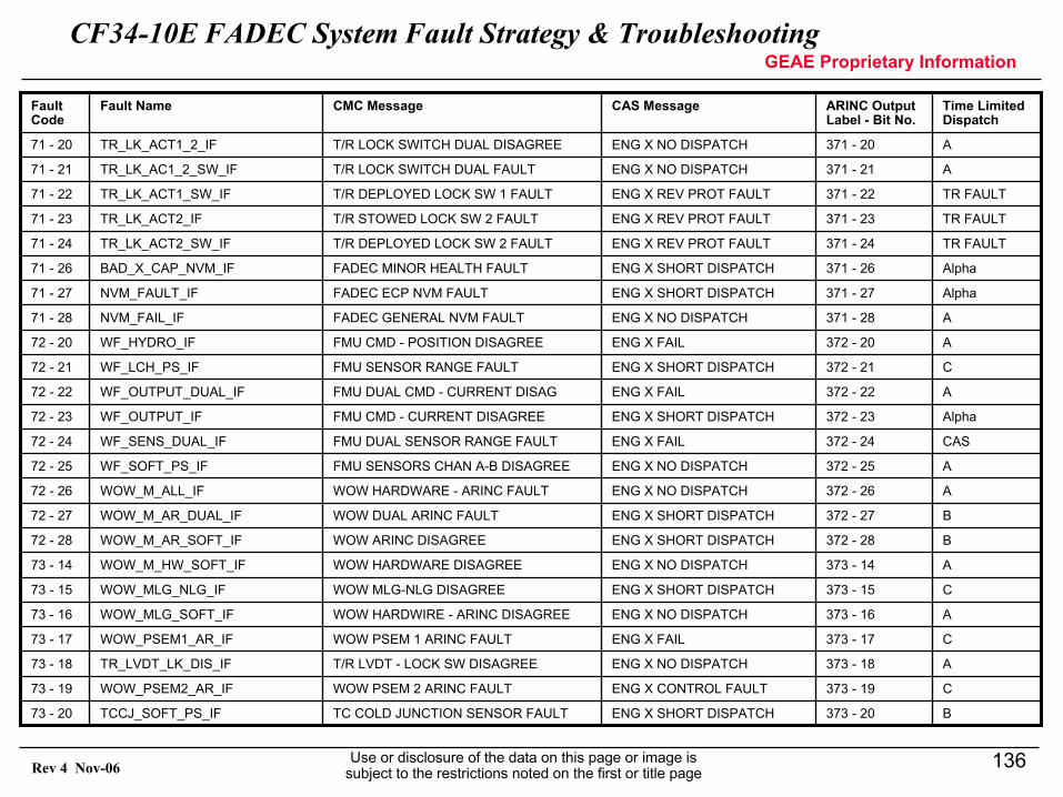
CF34-10E FADEC System Fault Strategy & TroubleshootingGEAE Proprietary Information
Use or disclosure of the data on this page or image is subject to the restrictions noted on the first or title page
136Rev 4 Nov-06
B373 - 20ENG X SHORT DISPATCHTC COLD JUNCTION SENSOR FAULTTCCJ_SOFT_PS_IF73 - 20
C373 - 19ENG X CONTROL FAULTWOW PSEM 2 ARINC FAULTWOW_PSEM2_AR_IF73 - 19
A373 - 18ENG X NO DISPATCHT/R LVDT - LOCK SW DISAGREETR_LVDT_LK_DIS_IF73 - 18
C373 - 17ENG X FAILWOW PSEM 1 ARINC FAULTWOW_PSEM1_AR_IF73 - 17
A373 - 16ENG X NO DISPATCHWOW HARDWIRE - ARINC DISAGREEWOW_MLG_SOFT_IF73 - 16
C373 - 15ENG X SHORT DISPATCHWOW MLG-NLG DISAGREEWOW_MLG_NLG_IF73 - 15
A373 - 14ENG X NO DISPATCHWOW HARDWARE DISAGREEWOW_M_HW_SOFT_IF73 - 14
B372 - 28ENG X SHORT DISPATCHWOW ARINC DISAGREEWOW_M_AR_SOFT_IF72 - 28
B372 - 27ENG X SHORT DISPATCHWOW DUAL ARINC FAULTWOW_M_AR_DUAL_IF72 - 27
A372 - 26ENG X NO DISPATCHWOW HARDWARE - ARINC FAULTWOW_M_ALL_IF72 - 26
A372 - 25ENG X NO DISPATCHFMU SENSORS CHAN A-B DISAGREEWF_SOFT_PS_IF72 - 25
CAS372 - 24ENG X FAILFMU DUAL SENSOR RANGE FAULTWF_SENS_DUAL_IF72 - 24
Alpha372 - 23ENG X SHORT DISPATCHFMU CMD - CURRENT DISAGREEWF_OUTPUT_IF72 - 23
A372 - 22ENG X FAILFMU DUAL CMD - CURRENT DISAGWF_OUTPUT_DUAL_IF72 - 22
C372 - 21ENG X SHORT DISPATCHFMU SENSOR RANGE FAULTWF_LCH_PS_IF72 - 21
A372 - 20ENG X FAILFMU CMD - POSITION DISAGREEWF_HYDRO_IF72 - 20
A371 - 28ENG X NO DISPATCHFADEC GENERAL NVM FAULTNVM_FAIL_IF71 - 28
Alpha371 - 27ENG X SHORT DISPATCHFADEC ECP NVM FAULTNVM_FAULT_IF71 - 27
Alpha371 - 26ENG X SHORT DISPATCHFADEC MINOR HEALTH FAULTBAD_X_CAP_NVM_IF71 - 26
TR FAULT371 - 24ENG X REV PROT FAULTT/R DEPLOYED LOCK SW 2 FAULTTR_LK_ACT2_SW_IF71 - 24
TR FAULT371 - 23ENG X REV PROT FAULTT/R STOWED LOCK SW 2 FAULTTR_LK_ACT2_IF71 - 23
TR FAULT371 - 22ENG X REV PROT FAULTT/R DEPLOYED LOCK SW 1 FAULTTR_LK_ACT1_SW_IF71 - 22
A371 - 21ENG X NO DISPATCHT/R LOCK SWITCH DUAL FAULTTR_LK_AC1_2_SW_IF71 - 21
A371 - 20ENG X NO DISPATCHT/R LOCK SWITCH DUAL DISAGREETR_LK_ACT1_2_IF71 - 20
Time Limited Dispatch
ARINC Output Label - Bit No.
CAS MessageCMC MessageFault NameFault Code
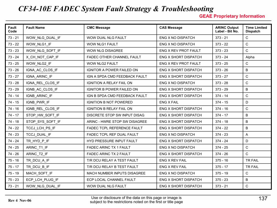
CF34-10E FADEC System Fault Strategy & TroubleshootingGEAE Proprietary Information
Use or disclosure of the data on this page or image is subject to the restrictions noted on the first or title page
137Rev 4 Nov-06
C373 - 21ENG X SHORT DISPATCHWOW DUAL NLG FAULTWOW_NLG_DUAL_IF73 - 21
B375 - 23ENG X SHORT DISPATCHECP LOCAL CHANNEL FAULTECP_LCH_PLUG_IF75 - 23
C375 - 19ENG X NO DISPATCHMACH NUMBER INPUTS DISAGREEMACH_SOFT_IF75 - 19
TR FAIL375 - 17ENG X REV FAILT/R DCU RELAY B TEST FAULTTR_DCU_B_IF75 - 17
TR FAIL375 - 16ENG X REV FAILT/R DCU RELAY A TEST FAULTTR_DCU_A_IF75 - 16
C374 - 26ENG X SHORT DISPATCHFADEC ARINC TX 2 FAULTARINC_T2_IF74 - 26
C374 - 25ENG X NO DISPATCHFADEC ARINC TX 1 FAULTARINC_T1_IF74 - 25
D374 - 24ENG X SHORT DISPATCHHYD PRESSURE INPUT FAULTTR_HYD_P_IF74 - 24
A374 - 23ENG X NO DISPATCHFADEC TCPL REF DUAL FAULTTCCJ_DUAL_IF74 - 23
B374 - 22ENG X SHORT DISPATCHFADEC TCPL REFERENCE FAULTTCCJ_LCH_PS_IF74 - 22
B374 - 18ENG X SHORT DISPATCHARINC - HWRE STOP SW DISAGREESTOP_SYS_SOFT_IF74 - 18
B374 - 17ENG X SHORT DISPATCHDISCRETE STOP SW INPUT DISAGSTOP_HW_SOFT_IF74 - 17
C374 - 16ENG X SHORT DISPATCHIGNITION B RELAY FAIL ONIGNB_REL_CLOS_IF74 - 16
D374 - 15ENG X FAILIGNITION B NOT POWEREDIGNB_PWR_IF74 - 15
C374 - 14ENG X SHORT DISPATCHIGN B SPDA CMD FEEDBACK FAULTIGNB_ARINC_IF74 - 14
B373 - 29ENG X SHORT DISPATCHIGNITOR B POWER FAILED ONIGNB_AC_CLOS_IF73 - 29
C373 - 28ENG X NO DISPATCHIGNITION A RELAY FAIL ONIGNA_REL_CLOS_IF73 - 28
C373 - 27ENG X SHORT DISPATCHIGN A SPDA CMD FEEDBACK FAULTIGNA_ARINC_IF73 - 27
B373 - 26ENG X SHORT DISPATCHIGNITOR A POWER FAILED ONIGNA_AC_CLOS_IF73 - 26
C373 - 25ENG X REV PROT FAULTWOW NLG2 FAULTWOW_NLG2_IF73 - 25
Alpha373 - 24ENG X SHORT DISPATCHFADEC OTHER CHANNEL FAULTX_CH_NOT_CAP_IF73 - 24
C373 - 23ENG X REV PROT FAULTWOW NLG DISAGREEWOW_NLG_SOFT_IF73 - 23
C373 - 22ENG X NO DISPATCHWOW NLG1 FAULTWOW_NLG1_IF73 - 22
C373 - 21ENG X NO DISPATCHWOW DUAL NLG FAULTWOW_NLG_DUAL_IF73 - 21
Time Limited Dispatch
ARINC Output Label - Bit No.
CAS MessageCMC MessageFault NameFault Code
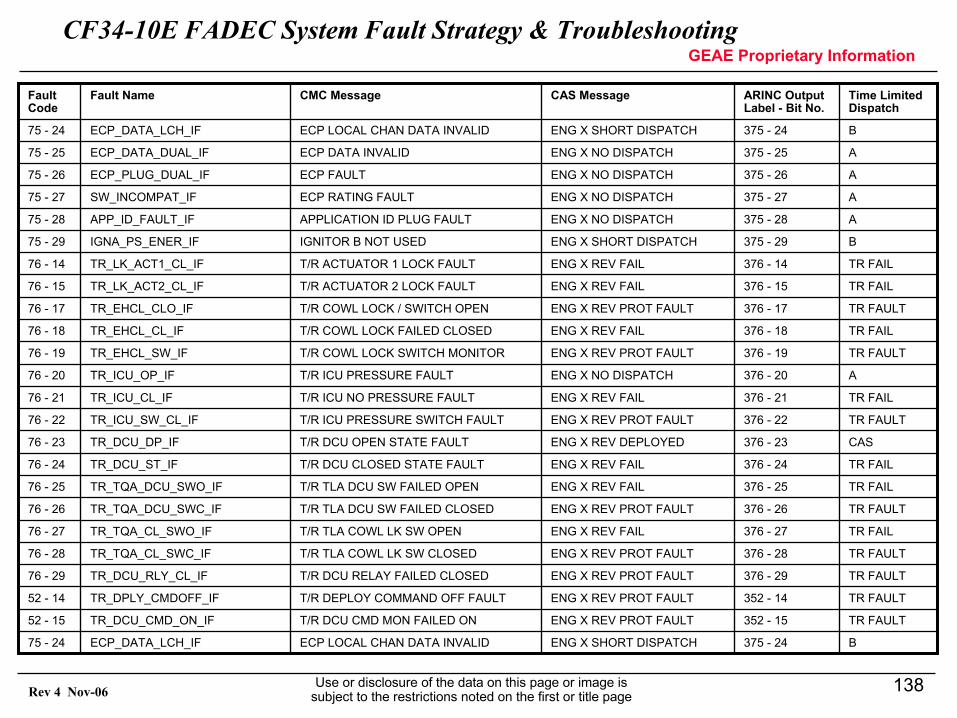
CF34-10E FADEC System Fault Strategy & TroubleshootingGEAE Proprietary Information
Use or disclosure of the data on this page or image is subject to the restrictions noted on the first or title page
138Rev 4 Nov-06
B375 - 24ENG X SHORT DISPATCHECP LOCAL CHAN DATA INVALIDECP_DATA_LCH_IF75 - 24
TR FAULT352 - 15ENG X REV PROT FAULTT/R DCU CMD MON FAILED ONTR_DCU_CMD_ON_IF52 - 15
TR FAULT352 - 14ENG X REV PROT FAULTT/R DEPLOY COMMAND OFF FAULTTR_DPLY_CMDOFF_IF52 - 14
TR FAULT376 - 29ENG X REV PROT FAULTT/R DCU RELAY FAILED CLOSEDTR_DCU_RLY_CL_IF76 - 29
TR FAULT376 - 28ENG X REV PROT FAULTT/R TLA COWL LK SW CLOSEDTR_TQA_CL_SWC_IF76 - 28
TR FAIL376 - 27ENG X REV FAILT/R TLA COWL LK SW OPENTR_TQA_CL_SWO_IF76 - 27
TR FAULT376 - 26ENG X REV PROT FAULTT/R TLA DCU SW FAILED CLOSEDTR_TQA_DCU_SWC_IF76 - 26
TR FAIL376 - 25ENG X REV FAILT/R TLA DCU SW FAILED OPENTR_TQA_DCU_SWO_IF76 - 25
TR FAIL376 - 24ENG X REV FAILT/R DCU CLOSED STATE FAULTTR_DCU_ST_IF76 - 24
CAS376 - 23ENG X REV DEPLOYEDT/R DCU OPEN STATE FAULTTR_DCU_DP_IF76 - 23
TR FAULT376 - 22ENG X REV PROT FAULTT/R ICU PRESSURE SWITCH FAULTTR_ICU_SW_CL_IF76 - 22
TR FAIL376 - 21ENG X REV FAILT/R ICU NO PRESSURE FAULTTR_ICU_CL_IF76 - 21
A376 - 20ENG X NO DISPATCHT/R ICU PRESSURE FAULTTR_ICU_OP_IF76 - 20
TR FAULT376 - 19ENG X REV PROT FAULTT/R COWL LOCK SWITCH MONITORTR_EHCL_SW_IF76 - 19
TR FAIL376 - 18ENG X REV FAILT/R COWL LOCK FAILED CLOSEDTR_EHCL_CL_IF76 - 18
TR FAULT376 - 17ENG X REV PROT FAULTT/R COWL LOCK / SWITCH OPENTR_EHCL_CLO_IF76 - 17
TR FAIL376 - 15ENG X REV FAILT/R ACTUATOR 2 LOCK FAULTTR_LK_ACT2_CL_IF76 - 15
TR FAIL376 - 14ENG X REV FAILT/R ACTUATOR 1 LOCK FAULTTR_LK_ACT1_CL_IF76 - 14
B375 - 29ENG X SHORT DISPATCHIGNITOR B NOT USEDIGNA_PS_ENER_IF75 - 29
A375 - 28ENG X NO DISPATCHAPPLICATION ID PLUG FAULTAPP_ID_FAULT_IF75 - 28
A375 - 27ENG X NO DISPATCHECP RATING FAULTSW_INCOMPAT_IF75 - 27
A375 - 26ENG X NO DISPATCHECP FAULTECP_PLUG_DUAL_IF75 - 26
A375 - 25ENG X NO DISPATCHECP DATA INVALIDECP_DATA_DUAL_IF75 - 25
B375 - 24ENG X SHORT DISPATCHECP LOCAL CHAN DATA INVALIDECP_DATA_LCH_IF75 - 24
Time Limited Dispatch
ARINC Output Label - Bit No.
CAS MessageCMC MessageFault NameFault Code
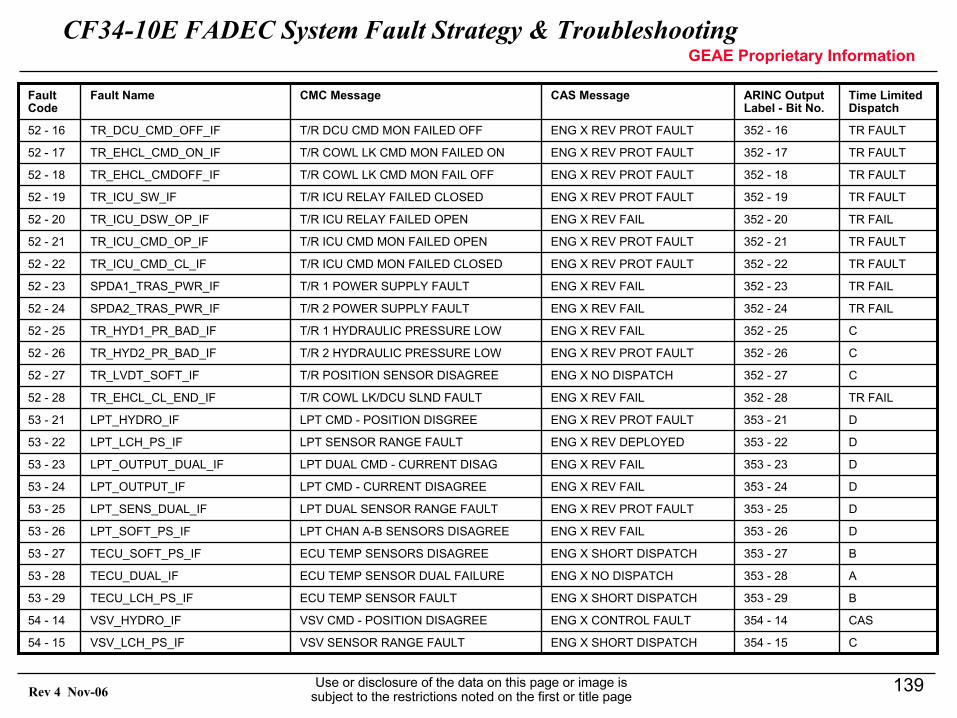
CF34-10E FADEC System Fault Strategy & TroubleshootingGEAE Proprietary Information
Use or disclosure of the data on this page or image is subject to the restrictions noted on the first or title page
139Rev 4 Nov-06
C354 - 15ENG X SHORT DISPATCHVSV SENSOR RANGE FAULTVSV_LCH_PS_IF54 - 15
CAS354 - 14ENG X CONTROL FAULTVSV CMD - POSITION DISAGREEVSV_HYDRO_IF54 - 14
B353 - 29ENG X SHORT DISPATCHECU TEMP SENSOR FAULTTECU_LCH_PS_IF53 - 29
A353 - 28ENG X NO DISPATCHECU TEMP SENSOR DUAL FAILURETECU_DUAL_IF53 - 28
B353 - 27ENG X SHORT DISPATCHECU TEMP SENSORS DISAGREETECU_SOFT_PS_IF53 - 27
D353 - 26ENG X REV FAILLPT CHAN A-B SENSORS DISAGREELPT_SOFT_PS_IF53 - 26
D353 - 25ENG X REV PROT FAULTLPT DUAL SENSOR RANGE FAULTLPT_SENS_DUAL_IF53 - 25
D353 - 24ENG X REV FAILLPT CMD - CURRENT DISAGREELPT_OUTPUT_IF53 - 24
D353 - 23ENG X REV FAILLPT DUAL CMD - CURRENT DISAGLPT_OUTPUT_DUAL_IF53 - 23
D353 - 22ENG X REV DEPLOYEDLPT SENSOR RANGE FAULTLPT_LCH_PS_IF53 - 22
D353 - 21ENG X REV PROT FAULTLPT CMD - POSITION DISGREELPT_HYDRO_IF53 - 21
TR FAIL352 - 28ENG X REV FAILT/R COWL LK/DCU SLND FAULTTR_EHCL_CL_END_IF52 - 28
C352 - 27ENG X NO DISPATCHT/R POSITION SENSOR DISAGREETR_LVDT_SOFT_IF52 - 27
C352 - 26ENG X REV PROT FAULTT/R 2 HYDRAULIC PRESSURE LOWTR_HYD2_PR_BAD_IF52 - 26
C352 - 25ENG X REV FAILT/R 1 HYDRAULIC PRESSURE LOWTR_HYD1_PR_BAD_IF52 - 25
TR FAIL352 - 24ENG X REV FAILT/R 2 POWER SUPPLY FAULTSPDA2_TRAS_PWR_IF52 - 24
TR FAIL352 - 23ENG X REV FAILT/R 1 POWER SUPPLY FAULTSPDA1_TRAS_PWR_IF52 - 23
TR FAULT352 - 22ENG X REV PROT FAULTT/R ICU CMD MON FAILED CLOSEDTR_ICU_CMD_CL_IF52 - 22
TR FAULT352 - 21ENG X REV PROT FAULTT/R ICU CMD MON FAILED OPENTR_ICU_CMD_OP_IF52 - 21
TR FAIL352 - 20ENG X REV FAILT/R ICU RELAY FAILED OPENTR_ICU_DSW_OP_IF52 - 20
TR FAULT352 - 19ENG X REV PROT FAULTT/R ICU RELAY FAILED CLOSEDTR_ICU_SW_IF52 - 19
TR FAULT352 - 18ENG X REV PROT FAULTT/R COWL LK CMD MON FAIL OFFTR_EHCL_CMDOFF_IF52 - 18
TR FAULT352 - 17ENG X REV PROT FAULTT/R COWL LK CMD MON FAILED ONTR_EHCL_CMD_ON_IF52 - 17
TR FAULT352 - 16ENG X REV PROT FAULTT/R DCU CMD MON FAILED OFFTR_DCU_CMD_OFF_IF52 - 16
Time Limited Dispatch
ARINC Output Label - Bit No.
CAS MessageCMC MessageFault NameFault Code
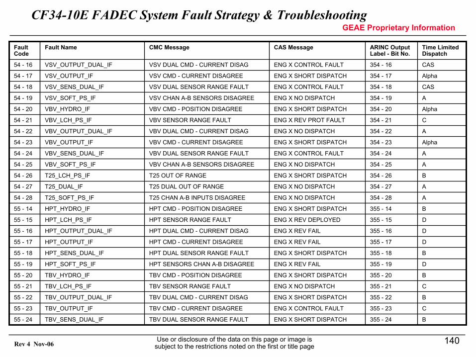
CF34-10E FADEC System Fault Strategy & TroubleshootingGEAE Proprietary Information
Use or disclosure of the data on this page or image is subject to the restrictions noted on the first or title page
140Rev 4 Nov-06
B355 - 24ENG X SHORT DISPATCHTBV DUAL SENSOR RANGE FAULTTBV_SENS_DUAL_IF55 - 24
C355 - 23ENG X CONTROL FAULTTBV CMD - CURRENT DISAGREETBV_OUTPUT_IF55 - 23
B355 - 22ENG X SHORT DISPATCHTBV DUAL CMD - CURRENT DISAGTBV_OUTPUT_DUAL_IF55 - 22
C355 - 21ENG X NO DISPATCHTBV SENSOR RANGE FAULTTBV_LCH_PS_IF55 - 21
B355 - 20ENG X SHORT DISPATCHTBV CMD - POSITION DISAGREETBV_HYDRO_IF55 - 20
D355 - 19ENG X REV FAILHPT SENSORS CHAN A-B DISAGREEHPT_SOFT_PS_IF55 - 19
B355 - 18ENG X SHORT DISPATCHHPT DUAL SENSOR RANGE FAULTHPT_SENS_DUAL_IF55 - 18
D355 - 17ENG X REV FAILHPT CMD - CURRENT DISAGREEHPT_OUTPUT_IF55 - 17
D355 - 16ENG X REV FAILHPT DUAL CMD - CURRENT DISAGHPT_OUTPUT_DUAL_IF55 - 16
D355 - 15ENG X REV DEPLOYEDHPT SENSOR RANGE FAULTHPT_LCH_PS_IF55 - 15
B355 - 14ENG X SHORT DISPATCHHPT CMD - POSITION DISAGREEHPT_HYDRO_IF55 - 14
A354 - 28ENG X NO DISPATCHT25 CHAN A-B INPUTS DISAGREET25_SOFT_PS_IF54 - 28
A354 - 27ENG X NO DISPATCHT25 DUAL OUT OF RANGET25_DUAL_IF54 - 27
B354 - 26ENG X SHORT DISPATCHT25 OUT OF RANGET25_LCH_PS_IF54 - 26
A354 - 25ENG X NO DISPATCHVBV CHAN A-B SENSORS DISAGREEVBV_SOFT_PS_IF54 - 25
A354 - 24ENG X CONTROL FAULTVBV DUAL SENSOR RANGE FAULTVBV_SENS_DUAL_IF54 - 24
Alpha354 - 23ENG X SHORT DISPATCHVBV CMD - CURRENT DISAGREEVBV_OUTPUT_IF54 - 23
A354 - 22ENG X NO DISPATCHVBV DUAL CMD - CURRENT DISAGVBV_OUTPUT_DUAL_IF54 - 22
C354 - 21ENG X REV PROT FAULTVBV SENSOR RANGE FAULTVBV_LCH_PS_IF54 - 21
Alpha354 - 20ENG X SHORT DISPATCHVBV CMD - POSITION DISAGREEVBV_HYDRO_IF54 - 20
A354 - 19ENG X NO DISPATCHVSV CHAN A-B SENSORS DISAGREEVSV_SOFT_PS_IF54 - 19
CAS354 - 18ENG X CONTROL FAULTVSV DUAL SENSOR RANGE FAULTVSV_SENS_DUAL_IF54 - 18
Alpha354 - 17ENG X SHORT DISPATCHVSV CMD - CURRENT DISAGREEVSV_OUTPUT_IF54 - 17
CAS354 - 16ENG X CONTROL FAULTVSV DUAL CMD - CURRENT DISAGVSV_OUTPUT_DUAL_IF54 - 16
Time Limited Dispatch
ARINC Output Label - Bit No.
CAS MessageCMC MessageFault NameFault Code
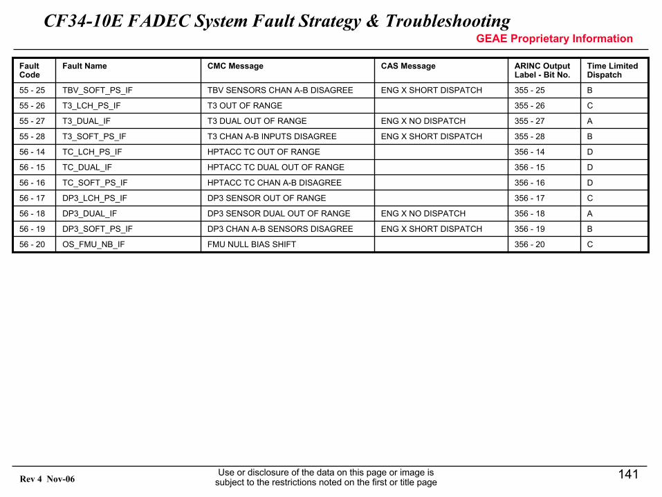
CF34-10E FADEC System Fault Strategy & TroubleshootingGEAE Proprietary Information
Use or disclosure of the data on this page or image is subject to the restrictions noted on the first or title page
141Rev 4 Nov-06
C356 - 20FMU NULL BIAS SHIFTOS_FMU_NB_IF56 - 20
B356 - 19ENG X SHORT DISPATCHDP3 CHAN A-B SENSORS DISAGREEDP3_SOFT_PS_IF56 - 19
A356 - 18ENG X NO DISPATCHDP3 SENSOR DUAL OUT OF RANGEDP3_DUAL_IF56 - 18
C356 - 17DP3 SENSOR OUT OF RANGEDP3_LCH_PS_IF56 - 17
D356 - 16HPTACC TC CHAN A-B DISAGREETC_SOFT_PS_IF56 - 16
D356 - 15HPTACC TC DUAL OUT OF RANGETC_DUAL_IF56 - 15
D356 - 14HPTACC TC OUT OF RANGETC_LCH_PS_IF56 - 14
B355 - 28ENG X SHORT DISPATCHT3 CHAN A-B INPUTS DISAGREET3_SOFT_PS_IF55 - 28
A355 - 27ENG X NO DISPATCHT3 DUAL OUT OF RANGET3_DUAL_IF55 - 27
C355 - 26T3 OUT OF RANGET3_LCH_PS_IF55 - 26
B355 - 25ENG X SHORT DISPATCHTBV SENSORS CHAN A-B DISAGREETBV_SOFT_PS_IF55 - 25
Time Limited Dispatch
ARINC Output Label - Bit No.
CAS MessageCMC MessageFault NameFault Code
CF34-10E FADEC System Fault Strategy & TroubleshootingGEAE Proprietary Information
Use or disclosure of the data on this page or image is subject to the restrictions noted on the first or title page
142Rev 4 Nov-06
Appendix B –Acronyms
CF34-10E FADEC System Fault Strategy & TroubleshootingGEAE Proprietary Information
Use or disclosure of the data on this page or image is subject to the restrictions noted on the first or title page
143Rev 4 Nov-06
ACRONYMS AND ABBREVIATIONS• A/C Aircraft• A/I Approach Idle• ABS Absolute Value• ADS Air Data System• AI Anti-Icing• APR Automatic Power Reserve• ARINC Aeronautical Radio, Inc.• AT Autothrottle• ATS Air Turbine Starter• BCD Binary Coded Decimal• BIT Built-In Test• BNR Binary Numeric Representation• CMC Central Maintenance Computer• D/I Descent Idle• DCU Direction Control Unit (TRAS)• EBU Engine Buildup Unit• ECS Environmental Control System• EDP Engine-Driven Pump• EICAS Engine Indication Cockpit Annunciation System• F/I Flight Idle
CF34-10E FADEC System Fault Strategy & TroubleshootingGEAE Proprietary Information
Use or disclosure of the data on this page or image is subject to the restrictions noted on the first or title page
144Rev 4 Nov-06
ACRONYMS AND ABBREVIATIONS• FADEC Full Authority Digital Engine Control• FIFO First In First Out• FMU Fuel Metering Unit• G/I Ground Idle• GMO Ground Maintenance Override• HPTACC High Pressure Turbine Active Clearance Control• ICU Isolation Control Unit (TRAS)• IDG Integrated Drive Generator• IFSD In-Flight Shutdown• IMON Current Monitor• L/I Landing Idle• LOTC Loss of Thrust Control• LVDT Linear Variable Differential Transformer• MAU Modular Avionics Unit• MCOEI Max Continuous One Engine Inoperative• MFD Multi Function Display• MPR Manual Power Reserve• N1 Fan Speed• N2 Core Speed• NAI Nacelle Anti-Icing• NDOT Core Speed Acceleration Rate
CF34-10E FADEC System Fault Strategy & TroubleshootingGEAE Proprietary Information
Use or disclosure of the data on this page or image is subject to the restrictions noted on the first or title page
145Rev 4 Nov-06
ACRONYMS AND ABBREVIATIONS• OEI One Engine Operation• P Parity• P0 Ambient Pressure• PLA Power Lever Angle (≡TLA)• PMA Permanent Magnet Alternator• PRSOV Pressure Regulated Solenoid Operated Valve• PS3 Compressor Discharge Pressure• R/I Reverse Idle• RSS Root Sum Squared• RVDT Rotary Variable Differential Transformer• SDI Source Destination Identifier• SLS Sea Level Static• SM Status Matrix• SOV Solenoid Operated Valve• SPDA Secondary Power Distribution Assembly• SSM Sign / Status Matrix• STD Standard Day• T/O Take-off• T/R Thrust Reverser• T2 Fan Total Inlet Temperature
CF34-10E FADEC System Fault Strategy & TroubleshootingGEAE Proprietary Information
Use or disclosure of the data on this page or image is subject to the restrictions noted on the first or title page
146Rev 4 Nov-06
ACRONYMS AND ABBREVIATIONS• T25 Compressor Inlet Temperature• T3 Compressor Discharge Temperature• TBV Transient Bleed Valve• Tcase HPT Casing Temperature• ITT Inter-Turbine Temperature• TAMB Static Air Temperature (calculated)• TAT Aircraft Total Air Temperature• TLA Throttle Lever Angle (≡PLA)• TLD Time Limited Dispatch• TQA Throttle Quadrant Assembly• TRAS Thrust Reverser Actuation System• TRX Thrust Reverser position• VSV Variable Stator Vane• VBV Variable Bleed Valve• VMON Voltage Monitor• WAI Wing Anti-Icing• WF Fuel Flow• WF/P3 Ratio Units: ratio of fuel flow to PS3• WFX FMU metering Valve Position Feedback• WOW Weight on Wheels• WS Wheel Spin• WSD Wheel Spin Discrete
CF34-10E FADEC System Fault Strategy & TroubleshootingGEAE Proprietary Information
Use or disclosure of the data on this page or image is subject to the restrictions noted on the first or title page
147Rev 4 Nov-06
Appendix C –Externals & Mounts
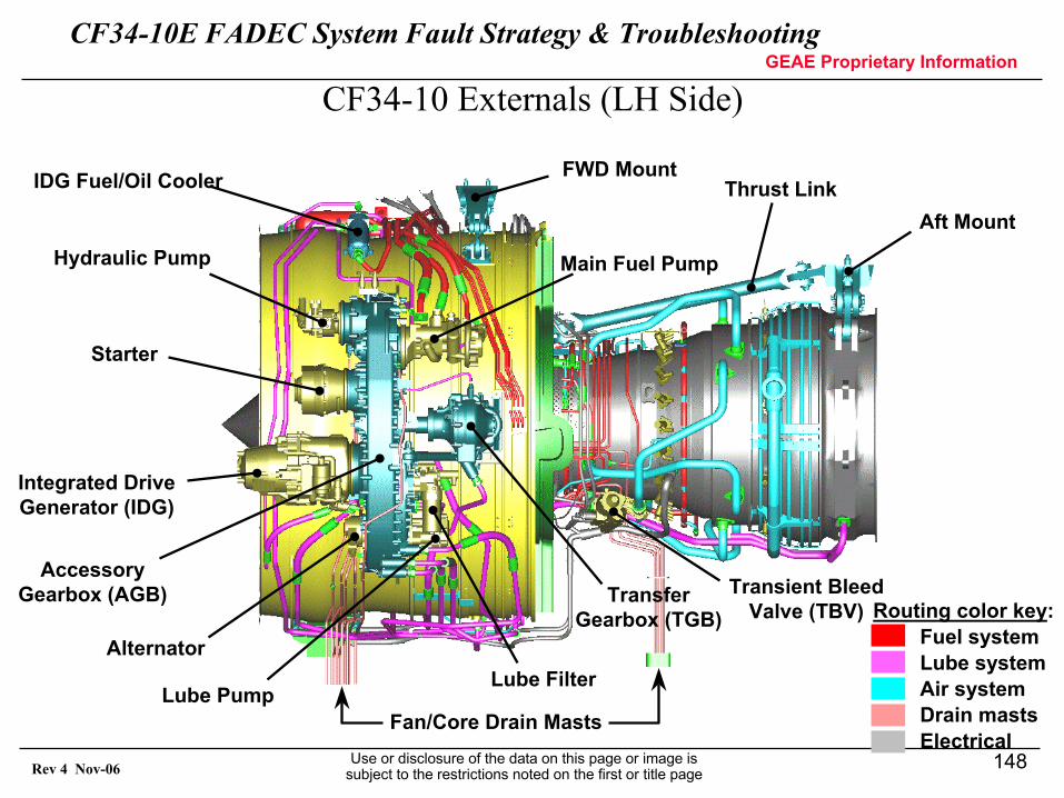
CF34-10E FADEC System Fault Strategy & TroubleshootingGEAE Proprietary Information
Use or disclosure of the data on this page or image is subject to the restrictions noted on the first or title page
148Rev 4 Nov-06
CF34-10 Externals (LH Side)
FWD Mount
Aft MountThrust Link
Fan/Core Drain Masts
Starter
Integrated DriveGenerator (IDG)
Hydraulic Pump Main Fuel Pump
Lube Pump
Transient BleedValve (TBV)
Lube FilterAlternator
TransferGearbox (TGB)
AccessoryGearbox (AGB)
IDG Fuel/Oil Cooler
Routing color key:Fuel systemLube systemAir systemDrain mastsElectrical
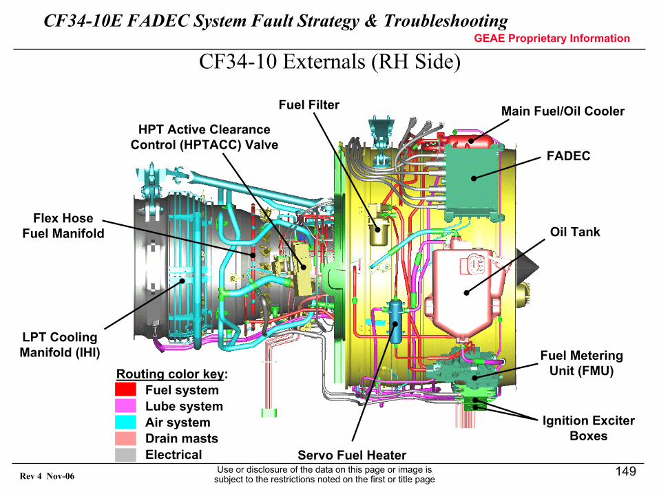
CF34-10E FADEC System Fault Strategy & TroubleshootingGEAE Proprietary Information
Use or disclosure of the data on this page or image is subject to the restrictions noted on the first or title page
149Rev 4 Nov-06
CF34-10 Externals (RH Side)
FADEC
Oil Tank
Fuel MeteringUnit (FMU)
Ignition ExciterBoxes
Servo Fuel Heater
HPT Active ClearanceControl (HPTACC) Valve
Fuel Filter Main Fuel/Oil Cooler
LPT CoolingManifold (IHI)
Flex HoseFuel Manifold
Routing color key:Fuel systemLube systemAir systemDrain mastsElectrical
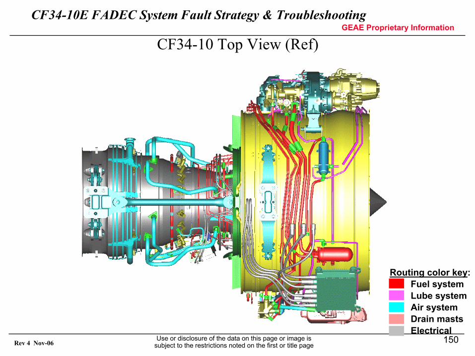
CF34-10E FADEC System Fault Strategy & TroubleshootingGEAE Proprietary Information
Use or disclosure of the data on this page or image is subject to the restrictions noted on the first or title page
150Rev 4 Nov-06
CF34-10 Top View (Ref)
Routing color key:Fuel systemLube systemAir systemDrain mastsElectrical
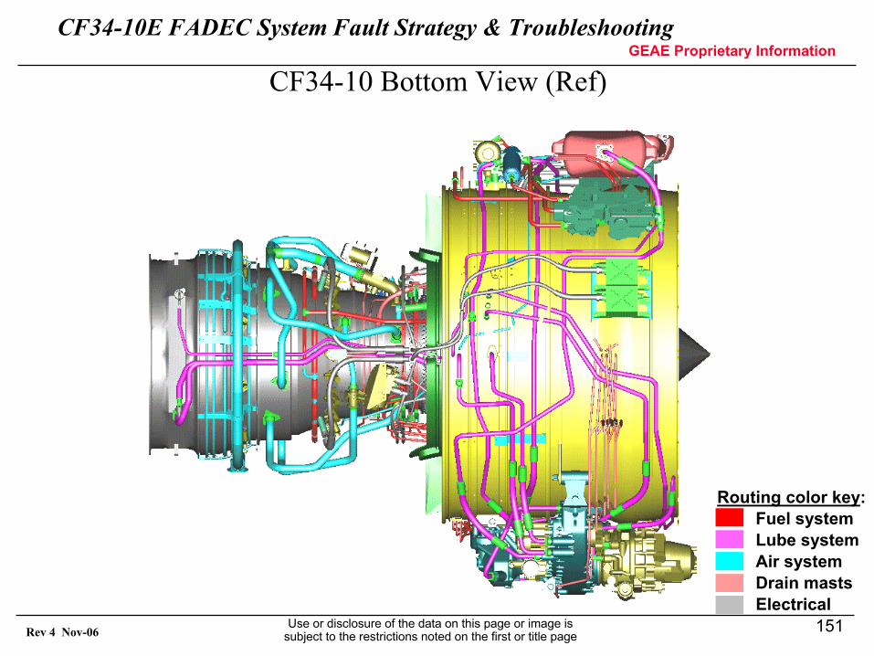
CF34-10E FADEC System Fault Strategy & TroubleshootingGEAE Proprietary Information
Use or disclosure of the data on this page or image is subject to the restrictions noted on the first or title page
151Rev 4 Nov-06
CF34-10 Bottom View (Ref)
Routing color key:Fuel systemLube systemAir systemDrain mastsElectrical