Experimental study of cone penetration in silica sand ... · The cone penetration test (CPT) has...
19
Arshad, M. I. et al. (2014). Ge ´otechnique 64, No. 7, 551–569 [http://dx.doi.org/10.1680/geot.13.P.179] 551 Experimental study of cone penetration in silica sand using digital image correlation M. I. ARSHAD , F. S. TEHRANI , M. PREZZI and R. SALGADO The problem of cone penetration, particularly deep penetration, remains one of the most challenging in geotechnical engineering. It involves large displacements, rotations and deformation of soil elements in the path of the cone as well as complex response of the soil, including crushing and the development of large mean stresses, to the displacements imposed by the penetration process. As a result, rigorous theoretical solutions are not available for this problem, and experimental simulations of penetration provide insights that would not otherwise be available. This paper presents the results of a series of cone penetration tests performed in a half-circular chamber in sand samples prepared with three silica sands with different crushability. Cone resistance was measured, and digital images of the cone penetrating into the sand samples were acquired simultaneously during the entire penetration process. The digital image correlation (DIC) technique was then used to process these images to obtain the soil displacement field resulting from cone penetration. The results of DIC analyses and measured cone resistance suggest that the soil displacement around an advancing cone depends on the density and crushability of the sand, as well as the depth of penetration. Tests on silica sands with different degrees of crushability show that, for shallow penetration, the displacement vectors near the cone tip are essentially vertical for crushable sand, transitioning to subvertical for less crushable sands. However, for deep penetration, the displacement vectors near the cone tip are mostly vertical below the cone tip. Crushing was observed immediately below and around the cone tip for all sands tested. After passage of the cone, the crushed particles form a thin, crushed particle band of thickness equal to about 2 . 5D 50 along the shaft, with a smaller percentage of crushed particles observed within an outer band with thickness equal to 4D 50 . KEYWORDS: model tests; particle crushing/crushability; piles; sands; soil/structure interaction INTRODUCTION The cone penetration test (CPT) has become a key tool in site characterisation, partly owing to its simplicity, and partly as a result of the development of cone resistance-based correlations for shallow foundation design (Schmertmann, 1970; Mayne & Poulos, 1999; Lee & Salgado, 2002; Lee et al., 2005; Foye et al., 2006; Lee et al., 2008; O’Loughlin & Lehane, 2010), pile design (Lee & Salgado, 1999; Lee et al., 2003; Jardine et al., 2005; Kolk et al., 2005; Xu et al., 2008; Foye et al., 2009; Seo et al., 2009; Niazi & Mayne, 2013) and liquefaction resistance estimation (Seed & De Alba, 1986; Stark & Olson, 1995; Salgado et al., 1997a; Robertson & Wride, 1998; Carraro et al., 2003; Idriss & Boulanger, 2006). The apparent simplicity of the CPT, how- ever, hides considerably complex mechanics (Salgado, 2013). These include possible partial drainage during pene- tration; particle size effects; the large displacements, rota- tions, shear deformations and mean stresses that develop around the cone; and the particle crushing that takes place near the cone. This complexity leads to significant chal- lenges in theoretical modelling of cone penetration. The most applicable analyses for sand have been based on cavity expansion analysis (Salgado et al., 1997b; Salgado & Ran- dolph, 2001; Salgado & Prezzi, 2007). The value of experimental modelling increases when the target problem, cone penetration in the present case, is difficult to solve theoretically. Even as attempts at a rigorous theoretical solution of the cone penetration problem gain sophistication, it will still be important to have companion experimental results that can be used to validate theoretical solutions. Image-based analysis methods can be used in laboratory investigations of the cone penetration process in particulate media. X-ray film photogrammetry (Robinsky et al., 1964) and, more recently, X-ray television (TV) imaging (Kobayashi & Fukagawa, 2003) have been used for this purpose. These techniques rely on embedded lead shot markers for tracking motion within the soil (White, 2002), and metal marker separation from the soil particles at large deformations affect the precision of the observed displacements. Additionally, the scanning time involved prevents the applicability of this tech- nique to observation of continuous penetration in large-scale models. The use of advanced non-destructive techniques, such as X-ray computed tomography (CT), in geotechnical model- ling has also been restricted to small-scale models (Otani, 2004; Morita et al., 2007; Ando ` et al., 2012; Paniagua et al., 2013). Stereo photogrammetry has been demonstrated for planar displacement measurement using a false relief tech- nique (Butterfield et al., 1970), but its accuracy is dependent upon the grain size of the deforming medium and texture contrast. Similarly, laser speckle interferometry (de Pater & Nieuwenhuis, 1986) has been used to observe the displace- ment field during cone penetration. This method relies on formation of laser fringe patterns due to sand grain move- ments and requires a minimum of 1 mm cone displacement for pattern recognition. Optical analysis around penetrating probes has also been employed (Allersma, 1987) for stress visualisation in plane-strain conditions, and then extended to displacement measurement by digital imaging of the same observation plane (Dijkstra et al., 2006). Transparent soil Manuscript received 27 October 2013; revised manuscript accepted 16 May 2014. Published online ahead of print 30 June 2014. Discussion on this paper closes on 1 December 2014, for further details see p. ii. Purdue University, West Lafayette, USA. Downloaded by [ University of Newcastle] on [27/11/17]. Copyright © ICE Publishing, all rights reserved.
-
Upload
hoangxuyen -
Category
Documents
-
view
239 -
download
0
Transcript of Experimental study of cone penetration in silica sand ... · The cone penetration test (CPT) has...

Arshad, M. I. et al. (2014). Geotechnique 64, No. 7, 551–569 [http://dx.doi.org/10.1680/geot.13.P.179]
551
Experimental study of cone penetration in silica sand using digitalimage correlation
M. I . ARSHAD�, F. S . TEHRANI�, M. PREZZI� and R. SALGADO�
The problem of cone penetration, particularly deep penetration, remains one of the most challengingin geotechnical engineering. It involves large displacements, rotations and deformation of soilelements in the path of the cone as well as complex response of the soil, including crushing and thedevelopment of large mean stresses, to the displacements imposed by the penetration process. As aresult, rigorous theoretical solutions are not available for this problem, and experimental simulationsof penetration provide insights that would not otherwise be available. This paper presents the resultsof a series of cone penetration tests performed in a half-circular chamber in sand samples preparedwith three silica sands with different crushability. Cone resistance was measured, and digital images ofthe cone penetrating into the sand samples were acquired simultaneously during the entire penetrationprocess. The digital image correlation (DIC) technique was then used to process these images toobtain the soil displacement field resulting from cone penetration. The results of DIC analyses andmeasured cone resistance suggest that the soil displacement around an advancing cone depends on thedensity and crushability of the sand, as well as the depth of penetration. Tests on silica sands withdifferent degrees of crushability show that, for shallow penetration, the displacement vectors near thecone tip are essentially vertical for crushable sand, transitioning to subvertical for less crushable sands.However, for deep penetration, the displacement vectors near the cone tip are mostly vertical belowthe cone tip. Crushing was observed immediately below and around the cone tip for all sands tested.After passage of the cone, the crushed particles form a thin, crushed particle band of thickness equalto about 2.5D50 along the shaft, with a smaller percentage of crushed particles observed within anouter band with thickness equal to 4D50.
KEYWORDS: model tests; particle crushing/crushability; piles; sands; soil/structure interaction
INTRODUCTIONThe cone penetration test (CPT) has become a key tool insite characterisation, partly owing to its simplicity, and partlyas a result of the development of cone resistance-basedcorrelations for shallow foundation design (Schmertmann,1970; Mayne & Poulos, 1999; Lee & Salgado, 2002; Lee etal., 2005; Foye et al., 2006; Lee et al., 2008; O’Loughlin &Lehane, 2010), pile design (Lee & Salgado, 1999; Lee etal., 2003; Jardine et al., 2005; Kolk et al., 2005; Xu et al.,2008; Foye et al., 2009; Seo et al., 2009; Niazi & Mayne,2013) and liquefaction resistance estimation (Seed & DeAlba, 1986; Stark & Olson, 1995; Salgado et al., 1997a;Robertson & Wride, 1998; Carraro et al., 2003; Idriss &Boulanger, 2006). The apparent simplicity of the CPT, how-ever, hides considerably complex mechanics (Salgado,2013). These include possible partial drainage during pene-tration; particle size effects; the large displacements, rota-tions, shear deformations and mean stresses that developaround the cone; and the particle crushing that takes placenear the cone. This complexity leads to significant chal-lenges in theoretical modelling of cone penetration. Themost applicable analyses for sand have been based on cavityexpansion analysis (Salgado et al., 1997b; Salgado & Ran-dolph, 2001; Salgado & Prezzi, 2007).
The value of experimental modelling increases when thetarget problem, cone penetration in the present case, isdifficult to solve theoretically. Even as attempts at a rigorous
theoretical solution of the cone penetration problem gainsophistication, it will still be important to have companionexperimental results that can be used to validate theoreticalsolutions.
Image-based analysis methods can be used in laboratoryinvestigations of the cone penetration process in particulatemedia. X-ray film photogrammetry (Robinsky et al., 1964)and, more recently, X-ray television (TV) imaging (Kobayashi& Fukagawa, 2003) have been used for this purpose. Thesetechniques rely on embedded lead shot markers for trackingmotion within the soil (White, 2002), and metal markerseparation from the soil particles at large deformations affectthe precision of the observed displacements. Additionally, thescanning time involved prevents the applicability of this tech-nique to observation of continuous penetration in large-scalemodels. The use of advanced non-destructive techniques, suchas X-ray computed tomography (CT), in geotechnical model-ling has also been restricted to small-scale models (Otani,2004; Morita et al., 2007; Ando et al., 2012; Paniagua et al.,2013). Stereo photogrammetry has been demonstrated forplanar displacement measurement using a false relief tech-nique (Butterfield et al., 1970), but its accuracy is dependentupon the grain size of the deforming medium and texturecontrast. Similarly, laser speckle interferometry (de Pater &Nieuwenhuis, 1986) has been used to observe the displace-ment field during cone penetration. This method relies onformation of laser fringe patterns due to sand grain move-ments and requires a minimum of 1 mm cone displacementfor pattern recognition. Optical analysis around penetratingprobes has also been employed (Allersma, 1987) for stressvisualisation in plane-strain conditions, and then extended todisplacement measurement by digital imaging of the sameobservation plane (Dijkstra et al., 2006). Transparent soil
Manuscript received 27 October 2013; revised manuscript accepted16 May 2014. Published online ahead of print 30 June 2014.Discussion on this paper closes on 1 December 2014, for furtherdetails see p. ii.� Purdue University, West Lafayette, USA.
Downloaded by [ University of Newcastle] on [27/11/17]. Copyright © ICE Publishing, all rights reserved.

particles have been used for measurement of displacementduring penetrometer/pile penetration (Iskander et al., 2002;Liu, 2003; Lehane & Gill, 2004; Ni et al., 2010). In general,the major limitations of these methods are their relatively lowresolution and accuracy in measuring displacements of gran-ular materials and their reliance on photoelastic materials andsynthetic particles, which may not have properties similar tothose of real soils.
In the past decade, image correlation techniques, such asparticle image velocimetry (PIV) and digital image correla-tion (DIC), have gained attention in experimental geomech-anics. In the DIC technique, a transparent observationwindow, located exactly where one of the symmetry planesof a penetrating probe or model pile with a full cross sectionwould be (possible because the probe has a half crosssection), enables the observer to study the response of soilduring the penetration or loading process. After imageprocessing, the displacement field within the soil mass isobtained at different stages of the penetration or loadingprocess.
In a pioneering work, White & Bolton (2004) used thePIV technique to study the displacement of soil surroundinga model ‘pile’ during penetration under plane-strain condi-tions. In order to simulate three-dimensional (3D) penetra-tion, Liu (2010) performed centrifuge CPTs underaxisymmetric conditions combined with PIV image analysis.Centrifuge testing is similar to chamber testing with respectto the PIV/DIC application, with the advantage of continu-ous stress profiling. However, in most cases, deep penetra-tion of the cone is accompanied by intrusion of sandparticles between the cone and the transparent observationwindow, possibly reducing the accuracy of the analysis. Toreduce the sand intrusion problem at deep penetration inaxisymmetric models, a coarser sand is desirable; its use ina centrifuge test may, however, affect the results because ofparticle size effects, which can become significant at lowcone diameter-to-particle size ratios (Foray et al., 1998;Loukidis & Salgado, 2008; Salgado, 2013).
This paper describes CPTs performed in a half-circularDIC chamber to study the cone penetration process in silicasand with uniform density. The DIC technique was used tocompute the soil displacement at shallow and deep penetra-tion from images stored during penetration. The paperexamines the insights provided by the computed displace-ment fields.
MATERIALS AND METHODSTest equipment
The half-circular steel chamber used in the present re-search has a diameter Dc of 1680 mm and a height of1200 mm. Jacking and loading systems and a reaction frameenabled penetration of the model cone penetrometer (seeFig. 1) into the samples. The front wall of the half-circularDIC chamber is a reinforced poly(methyl methacrylate)(PMMA) sheet. The reinforcement comes from a steel framethat contains three observation windows, which allow ima-ging of the half-circular cone penetrometer and the sur-rounding soil medium during the penetration process. Aclear, annealed glass sheet is fixed behind the PMMA toprevent scratching of the PMMA by the sand particlesduring testing.
Calibration chamber testing offers the advantage that theinitial state of the soil is known; however, for chambers ofsmall diameter, the effect of the chamber boundaries onmodel piles or penetrating probes must be considered in theinterpretation of results (Ghionna & Jamiolkowski, 1991;Salgado et al., 1998). The effect of chamber boundaries canbe minimised by choosing an appropriate chamber-to-cone
diameter ratio (Salgado, 2013). The diameter dc of themodel cone penetrometer is 31.75 mm. A ratio of Dc /dc
greater than 50 was considered sufficient to minimise theeffect of the chamber boundaries on the tests while allowingpreparation of samples that are not unmanageably large. Thecone diameter-to-D50 ratio of the test sands remained greaterthan 20 to avoid scale effects (Gui & Bolton, 1998; Salgado,2013). Fig. 2 shows the brass model cone penetrometer,which consists of a half-circular rod section 915 mm long,to which a half-section conical tip with a 608 apex angle isattached. To measure the cone resistance qc during testing, acompression load cell with 10 kN capacity was embeddedbetween the cone tip and the rod (see Fig. 2).
A removable jacking system with 50 kN capacity wasused to push the penetrometer into the sand at a penetration
(a)
Half-circular penetrometerJacking system
1200 mm
1680 mm
Observationwindows
Top lid
Sand dischargevalve
Soil sampledepth 1000 mm
(b)
Fig. 1. Schematic arrangement of the half-circular DIC chamber:(a) front view; (b) side view
552 ARSHAD, TEHRANI, PREZZI AND SALGADO
Downloaded by [ University of Newcastle] on [27/11/17]. Copyright © ICE Publishing, all rights reserved.

rate of � 1 mm/s (0.83 mm/s). A 20 kN tension–compressionload cell embedded between the jack and the head of thepenetrometer measured the jacking load during penetration.A roller assembly consisting of three cam followers and acarefully aligned jacking system practically eliminated intru-sion of sand between the penetrometer and the glass. Greaseon the penetrometer surface in direct contact with the glassminimised friction.
A specially designed, half-circular, air–rubber bladder wasused to apply pressure on the top surface of the sample. Ahalf-circular steel plate was placed below the rubber bladderto ensure uniform pressure application on the top of thesample. A reaction steel lid was bolted on the top of thechamber to constrain the air bladder.
Image and data acquisition systemThe image acquisition system used to record the images
consists of three complementary metal-oxide-semiconductor(CMOS), machine-vision digital cameras with 5 mega pixel(MP) resolution. The cameras are equipped with compatiblehigh-resolution and low-distortion lenses of 12.5 mm fixedfocal length. A frame grabber with on-board memory wasused to record images during the penetration tests.
The sensors used for measuring the jacking force andcone resistance during cone penetration were connected to aseparate data acquisition system. Base boundary effects weremonitored during testing by a load cell installed in thesample at the base of the chamber along the cone penetra-tion path. Lateral boundary effects were monitored by two
miniature pressure transducers installed at and near thechamber boundary at sample mid-height.
Test sandsThe main test sand was a coarse-grained, unground silica
sand (#2Q-ROK). This sand, which was mined from theOriskany sandstone deposits at Berkeley Springs in WestVirginia, has angular particles (Fig. 3(a)) and is composed
900
800
700
600
500
400
300
200
100
0
�100
�200
Ver
tical
pos
ition
, ,
rela
tive
to c
one
tip: m
mh
�150 �100 �50 0 50 100 150
Horizontal position, : mmx
Cables
dc 31·75 mm�
20 kN in-linetension/compression
load cell
Observationwindow 2
Observationwindow 3
10 kN compressionload cell
Fig. 2. Configuration of half-circular model penetrometer
100 mμ
(a)
100 mμ
(b)
50 mμ
(c)
Fig. 3. Microscopic images of the test sands: (a) #2Q-ROK;(b) ASTM 20-30; (c) Ohio Gold Frac
CONE PENETRATION IN SILICA SAND USING DIGITAL IMAGE CORRELATION 553
Downloaded by [ University of Newcastle] on [27/11/17]. Copyright © ICE Publishing, all rights reserved.
mainly of quartz (silicon dioxide (SiO2) ¼ 99%), havingtraces of calcite. For comparison purposes, additional testswere performed with two other silica sands: ASTM-graded20-30 Ottawa sand (SiO2 ¼ 99.8%), henceforth referred toas ASTM 20-30, which has rounded particles (Fig. 3(b)),and Ohio Gold Frac sand (SiO2 ¼ 99.7%), which has sub-angular particles (Fig. 3(c)). These three sands are classifiedas poorly graded (SP) according to the Unified ClassificationSystem (ASTM D2487-11; ASTM, 2011). The maximumand minimum densities of the sands were determined basedon ASTM D4253-00 (ASTM, 2006a) and ASTM D4254-00(ASTM, 2006b). Table 1 provides the index properties of thetest sands.
During deep penetration, which induces large mean andshear stresses below the cone tip, particle crushing is ob-served in almost all sands (BCP Committee, 1971; White &Bolton, 2004; Otani et al., 2005; Yang et al., 2010). White& Bolton (2004) observed intense particle crushing ahead ofthe tip of a plane-strain penetrometer monotonically jackedinto silica and carbonate sands. Yang et al. (2010) performedcyclic loading tests on model, closed-ended steel pilesjacked into silica sand samples subjected to 150 kPa sur-charge. Three distinct zones were identified near the pileshaft that contained different percentages of crushed parti-cles ranging in size from 20 �m to 100 �m.
In order to compare the crushability characteristics of thetest sands, one-dimensional (1D) compression tests wereperformed on very dense samples (DR � 85%) with normalstresses of up to 10 MPa (Fig. 4). The relative breakageparameter Br, as defined by Hardin (1985), was then used toprovide an assessment of the crushability characteristics ofthe test sands. From the results of the 1D compression tests,the #2Q-ROK sand is the most crushable, with Br ¼ 10.51%;Ohio Gold Frac sand is of intermediate crushability, with
Br ¼ 2.56%; and ASTM 20-30 sand is the least crushable ofthe three silica sands, with Br ¼ 0.56%.
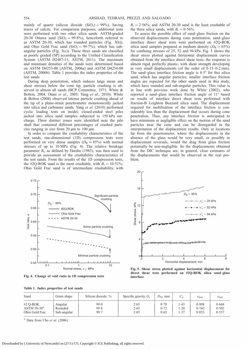
To assess the possible effect of sand–glass friction on theobserved displacements during cone penetration, sand–glassinterface direct shear tests were performed on #2Q-ROKsilica sand samples prepared at medium density (DR ¼ 65%)for confining stresses of 25, 52 and 94 kPa. Fig. 5 shows theshear stress plotted against horizontal displacement curvesobtained from the interface direct shear tests; the response isalmost rigid, perfectly plastic, with shear strength developingat very small displacements (of the order of 0.15–0.2 mm).The sand–glass interface friction angle is 8.58 for this silicasand, which has angular particles; smaller interface frictionangles are expected for the other sands used in this study,which have rounded and sub-angular particles. This value isin line with previous work done by White (2002), whoreported a sand–glass interface friction angle of 118 basedon results of interface direct shear tests performed withfraction-B Leighton Buzzard silica sand. The displacementrequired for mobilisation of the interface friction is con-siderably less than the displacement that occurs during conepenetration. Thus, any interface friction is anticipated tohave minimum or negligible effect on the motion of the sandparticles near the cone and can be disregarded in theinterpretation of the displacement results. Only at locationsfar from the penetrometer, where the displacements in theabsence of the glass would be very small, or possibly indisplacement reversals, would the drag from glass frictionpotentially be non-negligible. So the displacements obtainedfrom the DIC technique are, in general, close estimates ofthe displacements that would be observed in the real pro-blem.
Table 1. Index properties of test sands
Sand Grain shape Silicon dioxide: % Specific gravity, Gs D50: mm Cu emax emin
#2 Q-ROK Angular 99.0 2.65 0.78 1.43 0.998 0.668ASTM 20-30� Rounded 99.8 2.65 0.72 1.20 0.742 0.502Ohio Gold Frac Sub-angular 99.7 2.65 0.65 1.37 0.853 0.537
� Data from Cho et al. (2006).
0·45
0·50
0·55
0·60
0·65
0·70
0·75
0·1 1 10
Voi
d ra
tio, e
Normal stress, : MPaσ �n
#2Q-ROK
Ohio Gold Frac
ASTM 20-30
DR 85%�
Significant particlecrushing
Some particle crushing
Minimal particle crushing
Fig. 4. Change of void ratio in 1D compression tests
0
4
8
12
16
20
0 2 4 6 8
She
ar s
tres
s: k
Pa
Horizontal displacement: mm
DR 65%�
σ � �n 25 kPa
σ � �n 52 kPa
σ � �n 94 kPa
Fig. 5. Shear stress plotted against horizontal displacement fordirect shear tests performed on #2Q-ROK silica sand–glassinterface
554 ARSHAD, TEHRANI, PREZZI AND SALGADO
Downloaded by [ University of Newcastle] on [27/11/17]. Copyright © ICE Publishing, all rights reserved.

Digital image correlation fundamentalsThe DIC technique involves obtaining a sequence of
digital images of a body or a structure in motion and thenprocessing these images using an image correlation schemeto produce the displacements of material elements of thebody. Image correlation enables tracking of elements (groupsof particles) in time. There are two families of predefinedcorrelation criteria that are often used for this purpose (Panet al., 2009). The first group, referred to as the cross-correlation (CC) criteria, seeks a maximum correlation ofgrey level intensity of pixels across sequential images. Thesecond group, referred to as the sum-of-squared-differences(SSD) criteria, seeks the minimum difference in grey-levelintensity of an image pattern (subset) in the reference anddeformed/displaced images. Both families of correlation
criteria are in essence complementary and can be deducedfrom each other (Pan et al., 2009). The choice of thematching criterion depends upon the experimental condi-tions, nature of deformations, and the quality of the specklepattern or random texture. In general, as illustrated in Fig.6(a), a DIC algorithm (Pan et al., 2009) involves
(a) defining a virtual grid on the initial image (referenceimage)
(b) defining the subset size and search zone in the subsequentimage (deformed image)
(c) interpolating the discrete grey-level intensity of thedeformed image to form a continuous function
(d ) establishing the correlation between image sets using asuitable criterion
Reference image
Subset size (L)0x
y
Subsetspacing
f x y( , )i i
Reference subset
Correlation maximisation algorithm
Target subset
g x( ,�i y �i )
0 x
y
Deformed image
Displacement vector
(a)
ti ti�1 ti�2
ti n� �1ti n�
(b)
Fig. 6. Digital image correlation: (a) procedure outline for one subset; (b) incremental correlation
CONE PENETRATION IN SILICA SAND USING DIGITAL IMAGE CORRELATION 555
Downloaded by [ University of Newcastle] on [27/11/17]. Copyright © ICE Publishing, all rights reserved.

(e) obtaining average displacements at the intersection ofmeasurement grids.
A fundamental assumption in the DIC technique is thatthe image grey-level intensity pattern remains the samebefore and after motion but for some Gaussian noise (Suttonet al., 2009). In the case of large deformation problems,such as the cone penetration problem, some soil particlesmay disappear from the subset, resulting in loss of accuracydue to a mismatch between the subsets of the deformed andundeformed images. To avoid this problem, an incrementalcorrelation scheme was adopted in this study that involvescomparing an image at a given time ti with a subsequentimage at the next time step ti+1 (Fig. 6(b)). The accumulateddisplacements at any given time were calculated by integrat-ing the incremental displacement field obtained from theincremental correlation. A disadvantage of the incrementalcorrelation scheme is that the systematic error associatedwith the displacement obtained at any increment adds up. Tominimise the systematic error, instead of working with theentire set of images, an optimum number of images wereselected for processing. In addition, other measures wereadopted to enhance the accuracy of the image correlation,such as texture enhancement, use of a low-pass filter in theanalysis of the images, and use of improved correlationalgorithms accounting for subset deformation. Moreover, toavoid variation in the lighting conditions during the test, amatching criterion for image correlation based on a zero-normalised sum of squared differences was employed (Sut-ton et al., 2009). The commercial digital image correlationsoftware VIC-2D (Correlated Solutions, 2009) was used forprocessing the images taken during cone penetration. OtherDIC parameters that affect the measurement accuracy ofdisplacements were optimised through a parametric study;these factors include subset size, choice of correlation algo-rithm, interpolation function for subset displacement andimage intensity interpolated function.
Camera calibration. The displacement field obtained fromimage correlation is in pixels. To convert the pixel coordinatesto the object space coordinates, an image transformationmatrix is first obtained from camera calibration (White et al.,2003). To obtain the camera calibration parameters, a set of45 image control points were printed on a transparentlaminating film using a 1440 DPI printer. The calibrationtarget film covers the entire inner surface of the glass that is indirect contact with the PMMA. The centroids of these controlpoints in image space were obtained using the Matlabsoftware geoCENTROID (White et al., 2003). These controlpoints were then used to establish the camera calibrationparameters using the camera calibration toolbox for Matlab(Heikkila & Silven, 1997). A linear fit to the image-to-object
scale was chosen by minimising the standard deviation of theprojection error. This procedure was followed for all tests.
EXPERIMENTAL PROGRAMMETest matrix
A series of ten CPTs was performed in the DIC chamberin uniform sand samples (Table 2). In total, eight tests wereperformed on the most crushable silica sand (#2Q-ROK) withand without surcharge. Out of these eight tests, three testswere performed without any surcharge to investigate thedevelopment of the slip mechanism at shallow penetrationand the effect of stress level on the displacement field. Twotests were performed on the other two sands, ASTM 20-30sand and Ohio Gold Frac sand. The tests are identified by acode that specifies the sand density (L denotes ‘loose’, MDdenotes ‘medium dense’ and D denotes ‘dense’), surcharge(0 or 50 kPa), test number (a number from 1 to 10) and sandtype (#2Q-ROK, ASTM 20-30 and Ohio Gold Frac). Forexample, CPTL50-T4-#2Q-ROK identifies CPT number 4,performed on a loose #2Q-ROK sand sample with a sur-charge of 50 kPa.
Test procedureThe medium dense and dense sand samples were prepared
by air pluviation using a large pluviator (Lee et al., 2011)placed above the DIC chamber at a fixed position such thatthe sand drop height was always greater than the terminalsand fall height of 500 mm, determined through the calibra-tion procedure described by Rad & Tumay (1987). Thetarget sample densities were achieved by changing the flowrate through addition or removal of a diffuser sieve. Aslightly different procedure was used for preparation of loosesand samples. While carefully maintaining a drop height of400 mm, a half-circular pluviator without diffuser sieves wasplaced inside the DIC chamber and raised slowly as thesample was prepared. For sample density and uniformityverification, nine miniature thin tube samplers with diameterequal to 2 in (5.08 cm) were placed at different heightswithin the sand sample during sample preparation and wereused to determine density locally. The density variation in asample was determined to be within 2–3%. For the testsperformed with a surcharge of 50 kPa, the surcharge wasapplied gradually on top of the sample by inflating the half-circular, air–rubber bladder using a laboratory air-pressureline. A special cross-hair alignment device was used to alignthe cameras with the observation windows.
The penetrometer was subsequently jacked into the soilsample at a rate of 1 mm/s (0.83 mm/s). Digital images wereacquired simultaneously from three cameras during the pene-tration process at a constant frame rate of 2 frames/s. Thecone tip load Qc and the jacking force Qt were measured
Table 2. Test programme
Test code Surcharge: kPa Average relative density DR: % dc /D50 dc /Dc
CPTL0-T1-#2Q-ROK 0 45 41 53CPTMD0-T2-#2Q-ROK 0 65CPTD0-T3-#2Q-ROK 0 85CPTL50-T4-#2Q-ROK 50 45CPTL50-T5-#2Q-ROK 50 42CPTMD50-T6-#2Q-ROK 50 63CPTD50-T7-#2Q-ROK 50 85CPTD50-T8-#2Q-ROK 50 82CPTD50-T9-Ohio Gold Frac 50 87 59 53CPTD50-T10-ASTM 20-30 50 85 43
556 ARSHAD, TEHRANI, PREZZI AND SALGADO
Downloaded by [ University of Newcastle] on [27/11/17]. Copyright © ICE Publishing, all rights reserved.

throughout each test. Feedback from the chamber base loadcell below the cone path was used to monitor base boundaryeffects. Negligible chamber base boundary stresses weremeasured for penetration depths up to 15 to 20 conediameters, depending on sand type and density.
CONE PENETRATION RESISTANCEIn addition to the digital images acquired during the
CPTs, cone resistance profiles were obtained from the meas-urements made by the load cell embedded inside the conetip; these are illustrated in Fig. 7 and Fig. 8.
Figure 7(a) shows cone resistance profiles for the testsperformed in loose, medium dense and dense sand sampleswithout surcharge loading (CPTL0-T1-#2Q-ROK, CPTMD0-T2-#2Q-ROK and CPTD0-T3-#2Q-ROK). Fig. 7(b) showsthe qc profiles for all the CPTs performed with a surchargeof 50 kPa in the #2Q-ROK silica sand. Cone resistanceincreases with increasing initial sample relative density in alltests. In the loose and medium dense sand samples, cone tipresistance tends to stabilise earlier than in the dense sandsample. Fig. 8 shows the cone resistance profiles for the testsperformed in dense samples (DR ¼ 82%, 85% and 87%)prepared with three different silica sands (#2Q-ROK, OhioGold Frac and ASTM 20-30). These results clearly show theeffect of particle crushing on cone resistance, as the morecrushable sand (#2Q-ROK) offers less resistance to conepenetration than the sand of intermediate crushability (OhioGold Frac) and the sand of least crushability (ASTM 20-30).
DIC RESULTSPresentation of the results
The DIC analyses of images stored for each test produced
(a) incremental displacement field resulting from each0.415 mm increment of cone penetration between twoconsecutive frames
(b) soil displacement paths(c) post-penetration accumulated displacement field.
Figure 9 shows the coordinate reference system used toreport the DIC results. The cone penetration depth from the topof the sample at any given time is denoted by h�. The verticaldistance of a point in the domain with respect to the cone tip ish (h ¼ 0 at the cone tip, positive above the cone tip andnegative below it). Results are typically presented with h andh� normalised by the cone radius (h/rc and h�/rc). The horizon-tal distance from a point to the cone penetration axis is r,whereas the vertical distance of the point to the sample surfaceis z. Both r and z can be normalised with respect to the coneradius (r/rc and z/rc).
Soil displacement pattern during cone penetrationThe deformation pattern around an advancing cone has
historically been viewed through the prism of a slip mechan-ism (Salgado & Prezzi, 2007). Such a slip mechanism canbe inferred from the observation of the soil displacementfield in the immediate neighbourhood of the cone tip forsmall increments of cone penetration. Paniagua et al. (2013)used 3D X-ray CT and 3D DIC algorithms to study displace-ments and strains around a cone penetrometer pushed intosilt, and observed also that there was a pattern consistentwith the Salgado & Prezzi (2007) slip pattern. Fig. 10 andFig. 11 show the evolution of the slip mechanism duringincremental cone penetration. For each of the analysesshown in Fig. 10 and Fig. 11, the incremental displacementfield was obtained for an incremental penetration of2.075 mm (¼ 5 3 0.415 mm ¼ 2.075 mm increment of cone
penetration between images i and (i + 5)), which corre-sponds to 0.13rc. The cone displacement in Fig. 10 and Fig.11 is shown without magnification, but the displacementvectors are magnified by a factor of 20 to allow bettervisualisation of the displacement field. Fig. 10 illustrates theevolution of the slip mechanism with increasing cone pene-tration for the CPTD0-T3-#2Q-ROK test. A free surfaceexists at the top of the sample since no surcharge wasapplied in this test. Image pairs of the cone penetration atthree normalised penetration depths (h�/rc ¼ 2, 6 and 22)were analysed to obtain the incremental displacement fieldsat each of these normalised penetration depths. As the cone
600
400
200
00 1 2 3 4 5
qc: MPa
Con
e pe
netr
atio
n de
pth,
: mm
z
CPTL0-T1-#2Q-ROK ( 45%)DR �
CPTMD0-T2-#2Q-ROK ( 65%)DR �
CPTD0-T3-#2Q-ROK ( 85%)DR �
600
400
200
00 5 10 15 20 25
qc: MPa
Con
e pe
netr
atio
n de
pth,
: mm
z
(a)
(b)
CPTL50-T4-#2Q-ROK ( 45%)DR �
CPTL50-T5-#2Q-ROK ( 42%)DR �
CPTMD50-T6-#2Q-ROK ( 63%)DR �
CPTD50-T7-#2Q-ROK ( 85%)DR �
CPTD50-T8-#2Q-ROK ( 82%)DR �
Fig. 7. Cone resistance profiles for penetration tests in #2Q-ROKsilica sand: (a) tests without surcharge; (b) tests with a surchargeof 50 kPa
CONE PENETRATION IN SILICA SAND USING DIGITAL IMAGE CORRELATION 557
Downloaded by [ University of Newcastle] on [27/11/17]. Copyright © ICE Publishing, all rights reserved.

first enters the sample, a shallow slip surface forms, with thedisplacement vectors fanning out in a pattern similar to thatof ‘classical’ bearing capacity failure (Salgado, 2008), withthe conical tip acting as a rigid driving wedge.
Figure 11 compares the displacement field aroundthe cone during incremental penetration for three testsperformed on samples of three different sands (CPTD50-T8-#2Q-ROK, CPTD50-T9-Ohio Gold Frac and CPTD50-T10-ASTM 20-30) with approximately the same density (82%,85% and 87%) subjected to the same surcharge (50 kPa).The figure shows the incremental displacement fields for twonormalised depths, h�/rc ¼ 6 and h�/rc ¼ 20, correspondingto normalised depths just prior to and after the onset ofparticle crushing in the soil zone below the cone (particle
crushing was visible to the naked eye through the observa-tion window). The incremental displacement field for h�/rc ¼ 6 (Figs 11(a)–11(c)) is such that, immediately belowthe cone tip, the displacement vectors are nearly vertical,while further away from it, the displacement vectors have alarger radial component. A transition zone is observed wherethe incremental displacement vectors rotate from the verticalto the radial direction, as suggested by Salgado & Prezzi(2007); this zone is more clearly observed for the leastcrushable sand (ASTM 20-30), for which the degree ofincremental displacement vector rotation is more pro-nounced. The incremental displacement field for h�/rc ¼ 20
500
400
300
200
100
00 6 12 18 24
qc: MPa
Con
e pe
netr
atio
n de
pth,
: mm
z
CPTD50-T9-Ohio Gold Frac ( 87%)DR �
CPTD50-T10-ASTM 20-30 ( 85%)DR �
CPTD50-T7-#2Q-ROK ( 85%)DR �
CPTD50-T8-#2Q-ROK ( 82%)DR �
Fig. 8. Comparison of cone resistances for #2Q-ROK, Ohio GoldFrac and ASTM 20-30 silica sands
0
10
20
30
Nor
mal
ised
dep
th,
/z
r c
10 5 0 5 10
Normalised radial position, / , relative to cone tipr rc
10
0
�10
Nor
mal
ised
ver
tical
pos
ition
,/
, rel
ativ
e to
con
e tip
hr c
r
z
h r*/ c
h r/ 0c �
h
hh
r
* Cone penetration depth from top of samplewith time
Vertical position relative to cone top( is positive above tip and negative below tip)Cone radius
�
�
�c
Fig. 9. Coordinate reference system for DIC data reporting
8
6
4
2
0
6 4 2 0 2 4 6
Nor
mal
ised
dep
th,
/z r c
Normalised radial position, / , relative to cone tip(a)
r rc
σs R
c
0 kPa, 85%* 2 , #2Q-ROK
� ��
Dh r
Cone incremental displacement 0·13� rc
Scale for incremental displacement vectors:0·063rc
12
10
8
6
4
6 4 2 0 2 4 6
Nor
mal
ised
dep
th,
/z r c
Normalised radial position, / , relative to cone tip(b)
r rc
σs R
c
0 kPa, 85%* 6 , #2Q-ROK
� ��
Dh r
Cone incremental displacement 0·13� rc
Scale for incremental displacement vectors:0·063rc
28
26
24
22
20
6 4 2 0 2 4 6
Nor
mal
ised
dep
th,
/z r c
Normalised radial position, / , relative to cone tip(c)
r rc
σs R
c
0 kPa, 85%* 22 , #2Q-ROK
� ��
Dh r
Cone incremental displacement 0·13� rc
Scale for incremental displacement vectors:0·063rc
Fig. 10. Evolution of slip pattern with penetration for test CPTD-T3-#2Q-ROK (�s 0 kPa, DR 85%): (a) h�/rc 2; (b) h�/rc 6;(c) h�/rc 22
558 ARSHAD, TEHRANI, PREZZI AND SALGADO
Downloaded by [ University of Newcastle] on [27/11/17]. Copyright © ICE Publishing, all rights reserved.

(Figs 11(d)–11(f)) illustrates that the overall incrementaldisplacement field becomes more vertical for all sands as thecone penetrates to a depth at which the sand particlessurrounding the conical tip undergo crushing (i.e., incremen-tal displacement rotation is less pronounced after particlecrushing becomes significant). In order to quantify thedegree of incremental displacement rotation within the tran-sition zone, the direction of the average incrementaldisplacement vectors was calculated within a subdomain ofthe soil domain obtained by revolution of the cross sectionshown in Fig. 11. This subdomain is essentially a cylinder,except for the conical space occupied by the penetrometertip, with radius 2dc and length extending from the cone
shoulder down to 1.25dc below the cone tip. The averagedirection of the incremental displacement vectors is calcu-lated using the product of the radius at which the displace-ment is observed and the magnitude of the displacement asa weight factor
Łave ¼Pnel
i¼1 Łili2�ridrPnel
i¼1 li2�ridr(1)
where
Łi ¼ tan�1 vi
ui
� �(2)
12
10
8
6
4
6 4 2 0 2 4 6
Nor
mal
ised
dep
th,
/z r c
Normalised radial position, / , relative to cone tip(a)
r rc
σs R
c
50 kPa, 85%* 6 , ASTM 20-30
� ��
Dh r
Cone incremental displacement 0·13� rc
Scale for incremental displacement vectors:0·063rc
12
10
8
6
4
6 4 2 0 2 4 6
Nor
mal
ised
dep
th,
/z r c
Normalised radial position, / , relative to cone tip(c)
r rc
σs R
c
50 kPa, 82%* 6 , #2Q-ROK
� ��
Dh r
Cone incremental displacement 0·13� rc
Scale for incremental displacement vectors:0·063rc
Direction of averagedisplacement vector 13·2°�
12
10
8
6
4
6 4 2 0 2 4 6
Nor
mal
ised
dep
th,
/z r c
Normalised radial position, / , relative to cone tip(b)
r rc
σs R
c
50 kPa, 87%* 6 , Ohio Gold Frac
� ��
Dh r
Cone incremental displacement 0·13� rc
Scale for incremental displacement vectors:0·063rc
Direction of averagedisplacement vector 33·2°�
Direction of averagedisplacement vector 31·5°�
Direction of averagedisplacement vector 33·0°�
26
24
22
20
18
6 4 2 0 2 4 6
Nor
mal
ised
dep
th,
/z r c
Normalised radial position, / , relative to cone tip(d)
r rc
σs R
c
50 kPa, 85%* 20 , ASTM 20-30
� ��
Dh r
Cone incremental displacement 0·13� rc
Scale for incremental displacement vectors:0·063rc
Direction of averagedisplacement vector 40·1°�
26
24
22
20
18
6 4 2 0 2 4 6
Nor
mal
ised
dep
th,
/z r c
Normalised radial position, / , relative to cone tip(e)
r rc
σs R
c
50 kPa, 87%* 20 , Ohio Gold Frac
� ��
Dh r
Cone incremental displacement 0·13� rc
Scale for incremental displacement vectors:0·063rc
Direction of averagedisplacement vector 36·8°�
26
24
22
20
18
6 4 2 0 2 4 6
Nor
mal
ised
dep
th,
/z r c
Normalised radial position, / , relative to cone tip(f)
r rc
σs R
c
50 kPa, 82%* 20 , #2Q-ROK
� ��
Dh r
Cone incremental displacement 0·13� rc
Scale for incremental displacement vectors:0·063rc
Fig. 11. Soil displacement pattern for ASTM 20-30, Ohio Gold Frac and #2Q-ROK silica sands prior to (h�/rc 6) and afterparticle crushing (h�/rc 20): (a) ASTM 20-30 at h�/rc 6; (b) Ohio Gold Frac at h�/rc 6; (c) #2Q-ROK at h�/rc 6; (d) ASTM20-30 at h�/rc 20; (e) Ohio Gold Frac at h�/rc 20; (f) #2Q-ROK at h�/rc 20
CONE PENETRATION IN SILICA SAND USING DIGITAL IMAGE CORRELATION 559
Downloaded by [ University of Newcastle] on [27/11/17]. Copyright © ICE Publishing, all rights reserved.

li ¼ffiffiffiffiffiffiffiffiffiffiffiffiffiffiffiu2
i þ v2i
q(3)
and ui and vi are the radial and vertical displacements ofevery soil element i within the averaging zone, respectively,Łi is the direction of the displacement vector of element iwith respect to the horizontal, li is the magnitude of thedisplacement vector for element i, nel is the number of soilelements within the subdomain where the average is calcu-lated, and ri is the radial distance between the centre ofelement i and the cone axis.
Characterisation of displacement zones around the coneFour zones providing a general, qualitative sense of the
displacement field and of processes taking place during conepenetration were identified based on the displacement pat-terns observed (Fig. 12(a)): zone I – a vertical compressionzone below the cone; zone II – a crushed particle bandalong the surface of the cone tip and shaft; zone III – atransition zone where the displacement vectors rotate fromthe vertical/sub-vertical direction to the radial direction; and
zone IV – a zone in which the direction of the displace-ments is approximately radial.
Figure 12(b) shows a vector plot of the incrementaldisplacement field obtained when the cone tip moved downfrom h� ¼ 6rc (initial position) to h� ¼ 7rc (final position)for CPTD50-T8-#2Q-ROK. The four zones are sketched inthe same plot. In zone I, vertical compression of the soildominates, and the incremental displacement vectors aremostly vertical. For small penetration increments, zone Iextends from the cone tip to h/rc � �3.8; for lower eleva-tions, the incremental vertical displacement reduces to lessthan 10% of the maximum incremental vertical displacementobserved in zone I. The maximum incremental verticaldisplacement is observed along the cone surface at r/rc � 0.5and h/rc ¼ 0.866.
Zone II forms due to intense shearing and particle crush-ing that takes place below the cone. The particles crushedbelow the cone are displaced laterally as the cone advances,and stay roughly in the same place as the cone continues inits advance. The finely crushed sand particles can be ob-served coating the cone tip and the entire cone shaft inclose-up views of the images captured during penetration.The maximum thickness of this zone, which was also ob-served by White & Bolton (2004) and Yang et al. (2010), is1.5–4 D50 at r/rc � 0.5 and h/rc ¼ 0.866.
Zone III exists immediately below the cone, where rota-tion of the incremental displacement field from a mainlyvertical direction to the radial direction occurs, as can beseen in Fig. 12(b). The inclination of the outer boundary ofthe transition zone III depends on sand crushability: themore crushable the sand, the less the boundary rotatesoutward (away from the cone). In zone IV, the incrementalsoil displacement field is purely radial, resembling the fieldthat would result from a cylindrical cavity expansion pro-cess, with minimal vertical incremental displacement ob-served.
Soil displacement in each of zones I though IV can bebetter understood by observing the displacement paths ofkey soil elements (labelled E1 through E6 in Fig. 12(a)).Fig. 13 shows the evolution of the normalised vertical andradial displacement increments ˜v/rc and ˜u/rc of elementsE1, E2, E3, E4, E5 and E6 shown in Fig. 12(a) due to apenetration of approximately 1rc (¼ 1.05 rc) from a depthh� ¼ 20rc. The incremental change in the displacement fieldwas deduced from the analysis of image sequences obtainedin tests CPTD50-T10-ASTM 20-30 and CPTD50-T8-#2Q-ROK. Fig. 13(a) shows the displacement path of elementE1 located just below the cone tip in zone I. Element E1
experiences a maximum vertical displacement increment˜v ¼ 0.68rc for the least crushable sand (ASTM 20-30)and ˜v ¼ 0.49rc for the most crushable sand (#2Q-ROK).The radial displacement change is negligible for both sands.It is seen in Fig. 13(a) that particle tracking for element E1
ends before cone penetration equal to rc is achieved. Forelement E2 next to the cone surface, maximum ˜v valuesof 0.34rc and 0.48rc were observed for the least and mostcrushable sand, respectively (Fig. 13(b)). The increase inthe normalised vertical displacement increment observed forthe most crushable silica sand #2Q-ROK is caused by theintense particle crushing occurring just below the cone tip.Element E2 undergoes a maximum radial displacementincrement equal to 0.17rc for the ASTM 20-30 sand and to0.13rc for the #2Q-ROK sand. Element E3 (Fig. 13(c)),located in the transition zone, experiences maximum radialand vertical displacement increments of 0.12rc and 0.10rc
for ASTM 20-30 sand, and 0.12rc and 0.16rc for #2Q-ROKsand. The displacement paths of elements E4, E5 and E6,located on the transition line between zone III and zone IV,indicate clearly that the radial component of the normalised
0 1 2 3 4 5r r/ c
Symbol shows element location(a)
2
1
0
�1
�2
�3
hr/c
Interface zoneCrushed particles band thickness 1·5–4� D50
II
E4
IV
Cavity expansion zone(radial displacement
dominates)E2
E3E5
E6
III
Transition zone(radial displacement
build-up)
E1
I
Axial compression zone(vertical displacement
dominates)Contour line correspondsto displacement ratio ( / ) 1u v �
Nor
mal
ised
dep
th,
/z r c
σs R
c
50 kPa, 82%* 7 , #2Q-ROK
� ��
Dh r
Normalised radial position, / , relative to cone tip(b)
r rc
Zone II
5
7
9
11
136 4 2 0 2 4 6
Zone I
Zone III
Zone IV
0·2rc
Scale for incremental displacement vectors
Fig. 12. Characterisation of displacement zones near cone duringa penetration equal to rc: (a) displacement zones; (b) displacementfield change
560 ARSHAD, TEHRANI, PREZZI AND SALGADO
Downloaded by [ University of Newcastle] on [27/11/17]. Copyright © ICE Publishing, all rights reserved.

0
0·2
0·4
0·6
0·8
20·0 20·4 20·8 21·2
Nor
mal
ised
dis
plac
emen
t cha
nge,
/an
d/
ΔΔ
u r
v r
cc
Normalised penetration depth, */(a)
h rc
σs
1 c
50 kPa
Element E : 0, 20·32
�
� �r z rRadial (ASTM 20-30, 85%)DR �
Vertical (ASTM 20-30, 85%)DR �
Radial (#2Q-ROK, 82%)DR �
Vertical #2Q-ROK( ,82%)DR �
σs
2 c c
50 kPa
Element E : 0·68 , 18·8
�
� �r r z rRadial (ASTM 20-30, 85%)DR �
Vertical (ASTM 20-30, 85%)DR �
Radial (#2Q-ROK, 82%)DR �
Vertical #2Q-ROK( , 82%)DR �
0
0·1
0·2
0·3
0·4
0·5
20·0 20·4 20·8 21·2
Nor
mal
ised
dis
plac
emen
t cha
nge,
/an
d/
ΔΔ
u r
v r
cc
Normalised penetration depth, */(b)
h rc
σs
3 c c
50 kPa
Element E : 1 , 19·2
�
� �r r z rRadial (ASTM 20-30, 85%)DR �
Vertical (ASTM 20-30, 85%)DR �
Radial (#2Q-ROK, 82%)DR �
Vertical #2Q-ROK( , 82%)DR �
σs
4 c c
50 kPa
Element E : 1·12 , 18·2
�
� �r r z rRadial (ASTM 20-30, 85%)DR �
Vertical (ASTM 20-30, 85%)DR �
Radial (#2Q-ROK, 82%)DR �
Vertical #2Q-ROK( , 82%)DR �
0
0·04
0·08
0·12
0·16
0·20
20·0 20·4 20·8 21·2
Nor
mal
ised
dis
plac
emen
t cha
nge,
/an
d/
ΔΔ
u r
v r
cc
Normalised penetration depth, */(c)
h rc
0
0·02
0·04
0·06
0·08
20·0 20·4 20·8 21·2
Nor
mal
ised
dis
plac
emen
t cha
nge,
/an
d/
ΔΔ
u r
v r
cc
Normalised penetration depth, */(d)
h rc
σs
5 c c
50 kPa
Element E : 2 , 19·2
�
� �r r z rRadial (ASTM 20-30, 85%)DR �
Vertical (ASTM 20-30, 85%)DR �
Radial (#2Q-ROK, 82%)DR �
Vertical #2Q-ROK( , 82%)DR �
σs
6 c c
50 kPa
Element E : 2·7 , 20
�
� �r r z rRadial (ASTM 20-30, 85%)DR �
Vertical (ASTM 20-30, 85%)DR �
Radial (#2Q-ROK, 82%)DR �
Vertical #2Q-ROK( , 82%)DR �
0
0·02
0·04
0·06
0·08
20·0 20·4 20·8 21·2
Nor
mal
ised
dis
plac
emen
t cha
nge,
/an
d/
ΔΔ
u r
v r
cc
Normalised penetration depth, */(e)
h rc
0
0·01
0·02
0·03
20·0 20·4 20·8 21·2
Nor
mal
ised
dis
plac
emen
t cha
nge,
/an
d/
ΔΔ
u r
v r
cc
Normalised penetration depth, */(f)
h rc
Fig. 13. Evolution of radial and vertical displacement change for 1rc penetration in the least crushable (CPTD50-T10-ASTM20-30) and most crushable (CPTD50-T8-#2Q-ROK) silica sands
CONE PENETRATION IN SILICA SAND USING DIGITAL IMAGE CORRELATION 561
Downloaded by [ University of Newcastle] on [27/11/17]. Copyright © ICE Publishing, all rights reserved.

displacement increment dominates there for both sands (seeFigs 13(d)–13(f)). However, the values of the radialdisplacement increment of elements located at larger radialoffsets from the cone tip (elements at positions E5 and E6)are smaller for the most crushable silica sand than thoseobserved for the least crushable silica sand (0.036rc and0.017rc, as opposed to 0.067rc and 0.02rc). These resultssuggest that deformation gets more localised near the conein the most crushable sand.
Displacement paths during continuous penetrationFigure 14 shows the displacement paths of nine elements
located at different radial offsets from the cone penetrationaxis (r/rc ¼ 0, 0.5, 1, 1.5, 2, 3, 4, 6 and 8) for test CPTD50-T8-#2Q-ROK. The displacement paths follow the coordi-nates of the centroid of each of the soil elements duringcone penetration from h� ¼ 0 to h� ¼ 30rc. The character-istics of the displacement paths of each of these elements,located initially at a depth z � 18rc, depend on their offsetposition with respect to the cone penetrometer path. Thedisplacement paths for soil elements A, B, C, D and Elocated at r/rc ¼ 0.5, 1, 1.5, 2 and 3 show that theseelements move away from the cone path, except near theend of the displacement paths, when the soil elements moveslightly towards the cone shaft instead (see Fig. 15). Forelements F, G and H located at r/rc ¼ 4, 6 and 8, no inward
displacement is observed at the end of the displacementpaths. Vertical displacements, which accumulate below thecone tip, decay sharply with increasing radial distance fromthe cone penetration path. As can be seen in Fig. 14, thesoil displacement paths radiating from the cone tip areinclined, with radial and vertical displacements decayingwith increasing radial distance from the cone tip. However,the rate of decay of the radial displacement with increasingdistance from the cone path is lower than that of the verticaldisplacement.
Figure 15 shows close-up views of the displacement pathsfor elements C and H located at r/rc ¼ 1.5 and at r/rc ¼ 8,respectively. For element C (Fig. 15(a)), the vertical compo-nent of displacement dominates initially, but, on further conepenetration, the displacement becomes more radial and,immediately after the cone shoulder crosses the elevation ofelement C, bends back towards the cone shaft. Fig. 15(b)shows the displacement path of element H. The radial andvertical displacements are of approximately the same magni-tude, with no inward displacement towards the shaft takingplace as the cone penetrates beyond the elevation of thiselement. As shown in Fig. 15(a), the motion of element Cundergoes a reversal, and its inward motion after thisreversal is significantly less than its outward displacement.Given that the inward motion of element C is small, frictionbetween the glass and the sand particles may have somewhatimpeded the inward motion since the motion reversal is
300
290
280
270
�20 0 20 40 60 80 100 120 140
Ver
tical
pos
ition
: mm
Horizontal position: mm
h r*/ 0c �
O A B C D E F G H
h r*/ 30c �
Thin crushed particle band 2·5� D50
End ofparticletracking
Con
e pe
netr
atio
n pa
th
σs R50 kPa, 82%, #2Q-ROK� �D
Vertical shearing
Intense rotation Element A (0·5 )rc
Element B (1·0 )rc
Element C (1·5 )rc
Element D (2·0 )rcElement E (3·0 )rc
Element O (0 )rc
Element E (4·0 )rc
Element F (6·0 )rc
Element G (8·0 )rc
Fig. 14. Displacement paths during cone penetration from h� 0rc to h� 30rc for soil elements O,A, B, C, D, E, F, G and H
562 ARSHAD, TEHRANI, PREZZI AND SALGADO
Downloaded by [ University of Newcastle] on [27/11/17]. Copyright © ICE Publishing, all rights reserved.

linked to unloading, which is initially approximately elastic.As mentioned earlier, the glass–soil stress–strain relationshipis a stiff, linear elastic curve, which makes it possible toestimate any drag that may have been present. The inwardmovement of element C and others like it reflect a decreasein radial stress after the cone shoulder crosses the elementelevations, and this drop in radial stress, experienced on thepenetrometer shaft, implies a drop of shear stress.
Figure 16 and Fig. 17 show the evolution of the normal-ised vertical and radial displacements of soil elements B, C,D and E as the cone penetrates from h� ¼ 0 to 23 and 25rc,respectively, for tests CPTL50-T4-#2Q-ROK and CPTD50-T8-#2Q-ROK. Initially, the soil elements are located atz ¼ 18rc for the loose sand sample and at z ¼ 18.5rc for thedense sample and at radial offsets of 1rc (element B), 1.5rc
(element C), 2rc (element D) and 3rc (element E) from thecone penetration axis.
Elements closer to the cone penetration path, such aselement B, are the first elements to sense the approachingcone. This happens when the vertical distance from elementB to the cone tip is equal to approximately 15 to 16rc for
loose and dense sand samples, respectively. The normalisedradial displacement of soil element B increases sharply whenthe cone tip reaches a distance of approximately 3–3.5rc
from soil element B and then moves closer to it. This buildup in radial stress is referred to in this paper as the cavityexpansion stage (Fig. 16(a)), the start of which is labelled aspoint 2 in Fig. 16. Element B is displaced radially anddownward as the cone passes by it. If one chooses to viewthe cone as stationary, then the element could be viewed asflowing around the cone face. The normalised radial soildisplacement of element B peaks when the cone shoulderstarts to align with it at the end of the cavity expansionprocess (see the peak in normalised displacements, identifiedas point 3 in Fig. 16(a) and Fig. 17(a)). During the cavityexpansion process, particle crushing is observed near thecone tip, with the crushed particle band starting to formalong the cone tip shoulder. A small reduction in normalisedradial and vertical displacements takes place after the cavityexpansion process (see points 3 and 4 in Fig. 16(a) and Fig.17(a)). For the elements located farther away from the cone,the peak in normalised radial displacement is either lesspronounced or no longer observed.
As the cone penetration continues, further vertical shear-ing is observed above the cone only within the thin crushedparticle band (zone II) along the shaft. Particle movement isvery random within the crushed particle band. As observedfrom close-up images of the cone penetration process, fortests performed with no surcharge (such as CPTD0-T3-#2Q-ROK), vertical particle movement is more pronounced inloose sand than in dense sand prior to particle crushing. Inthe case of the penetration tests performed in dense sandwith the 50 kPa surcharge (such as CPTD50-T8-#2Q-ROK),noticeable particle crushing takes place below the cone tip.Fig. 18 shows a close-up image of the soil in the zone(1.25rc 3 1rc) immediately next to the cone shaft forCPTD50-T8-#2Q-ROK. As shown in Fig. 18, a very thinband of thickness equal to about 2.5D50 with highly crushedparticles is observed right next to the cone shaft. Next tothis thin band, there is a 4D50-thick band consisting ofmoderately crushed sand particles.
Displacement paths below the cone tipFigure 19 shows normalised radial and vertical displace-
ment paths below the cone tip for h�/rc � 20 for testsperformed on sand samples prepared with three differentinitial densities (CPTL50-T4-#2Q-ROK, CPTMD50-T6-#2Q-ROK and CPTD50-T8-#2Q-ROK). The normalised displace-ment paths are given for soil elements located at r/rc � 1,1.5, 2, 3, 5 and 8. Both the radial and vertical normaliseddisplacements decrease with increasing r. The maximumvalue of the normalised radial displacement u/rc, which isobserved at an offset r/rc ¼ 1 along the shoulder of the conetip for dense and medium dense sand (Figs 19(a) and 19(c)),is equal to 0.33, whereas u/rc ¼ 0.28 at 0.5rc below the conetip for loose sand (Fig. 19(e)). The normalised radialdisplacement decays sharply with increasing vertical depthbelow the cone tip, becoming negligible (u/rc � 1% of themaximum normalised radial displacement observed) at h/rc
equal to �10, �12 and �14 for loose, medium and densesands, respectively (Figs 19(a), 19(c) and 19(e)). The oppo-site trend is observed in the case of the maximum normal-ised vertical displacement. The maximum normalisedvertical displacement v/rc observed at r/rc ¼ 1 at h ¼ 0 isequal to 0.8 for loose sand, as shown in Fig. 19(f), and toapproximately 0.6 for both the medium dense and densesands, as shown in Figs 19(b) and 19(d), respectively. Atlarger r/rc (� 1.5, 2, 3, 5 and 8) from the cone tip, the rateof decay of the normalised vertical displacement is greater
284
283
282
281
280
279
278
24 25 26 27 28 29 30
Ver
tical
pos
ition
: mm
Horizontal position: mm(a)
Cone shoulder alignswith element
Inward motiontowards penetrometer
shaft
Element C (1·5 )rc
σs R50 kPa, 82%, #2Q-ROK� �D
279·0
278·8
278·6
278·4
278·2
278·0
277·8
127·0 127·2 127·4 127·6 127·8 128·0 128·2
Ver
tical
pos
ition
: mm
Horizontal position: mm(b)
Cone shoulder alignswith element
No inward motion towardspenetrometer shaft
Element H (8 )rc
σs R50 kPa, 82%, #2Q-ROK� �D
Fig. 15. Displacement paths for: (a) element C and (b) element H
CONE PENETRATION IN SILICA SAND USING DIGITAL IMAGE CORRELATION 563
Downloaded by [ University of Newcastle] on [27/11/17]. Copyright © ICE Publishing, all rights reserved.

for the loose sand (v/rc � 0.30, 0.19, 0.13, 0.07 and 0.02)than for the dense (v/rc � 0.34, 0.26, 0.18, 0.11 and 0.08)and medium dense sands (v/rc � 0.32, 0.23, 0.16, 0.08 and0.04). Fig. 19 also shows that the vertical distance from thecone tip to the depth at which the normalised verticaldisplacement is equal to � 1% of the maximum normalisedvertical displacement, is slightly greater for the dense sand(h/rc � �14) than for the medium dense (h/rc � �12) andloose sands (h/rc � �10).
Post-penetration displacement fieldThe complete displacement field at any instance of the
penetration process can be obtained by combining thedisplacement data from all observation windows. Fig. 20shows the normalised displacement fields obtained as the conemoved from a normalised cone penetration depth h�/rc ¼ 0to approximately 20 for tests CPTL50-T4-#2Q-ROK and
CPTD50-T8-#2Q-ROK. At h�/rc � 20, the cone tip was lo-cated at a vertical distance of 40rc from the chamber baseboundary; at this position, there are no boundary effects on thedisplacement field. The contour plots of normalised radial andvertical displacements shown in Fig. 20 are approximatelysymmetric. The radial displacement extends to larger offsetdistances from the centre of the cone path in the dense sandthan in the loose sand. Sharp vertical displacements are ob-served within a small zone in the vicinity of the cone shaft(from r ¼ 0 to r/rc , 2) for all sands. Below the cone tip,vertical displacement (v/rc) contours ranging from 0.8 to 0.05extend vertically to h/rc � �8 and radially to r/rc � 5 for theloose sand. For the dense sand, the vertical displacementcontour extends to h/rc � �12 vertically and to r/rc � 8 ra-dially. The vertical displacement contours shown in Fig. 20 arecut off at the bottom of the chart because they reach the crossbar of the calibration chamber, which prevents visualisation ofdisplacements.
�0·2
0
0·2
0·4
0·6
0 10 20 30
Nor
mal
ised
dis
plac
emen
t, /
and
/u
rv
rc
c
Normalised penetration depth, */(a)
h rc
#2Q-ROK50 kPa, 45%σs R� �D
Element B: 1 , 18r r z r� �c c
Radial
Vertical
1: Start of axial compression2: Start of cavity expansion
(radial displacementbuild-up)
3: End of cavity expansion4: End of motion
3
3
4
4
2
1
�0·1
0
0·1
0·2
0·3
0·4
0 10 20 30
Nor
mal
ised
dis
plac
emen
t, /
and
/u
rv
rc
c
Normalised penetration depth, */(b)
h rc
#2Q-ROK50 kPa, 45%σs R� �D
Element C: 1·5 , 18r r z r� �c c
Radial
Vertical
1: Start of axial compression2: Start of cavity expansion
(radial displacementbuild-up)
3: End of cavity expansion4: End of motion
3
3
4
4
2
1
�0·1
0
0·1
0·2
0·3
0 10 20 30
Nor
mal
ised
dis
plac
emen
t, /
and
/u
rv
rc
c
Normalised penetration depth, */(c)
h rc
�0·1
0
0·1
0·2
0·3
0 10 20 30
Nor
mal
ised
dis
plac
emen
t, /
and
/u
rv
rc
c
Normalised penetration depth, */(d)
h rc
#2Q-ROK50 kPa, 45%σs R� �D
Element D: 2 , 18r r z r� �c c
Radial
Vertical
1: Start of axial compression2: Start of cavity expansion
(radial displacementbuild-up)
3: End of cavity expansion4: End of motion
3
3 4
4
2
1
#2Q-ROK50 kPa, 45%σs R� �D
Element E: 3 , 18r r z r� �c c
Radial
Vertical
1: Start of axial compression2: Start of cavity expansion
(radial displacementbuild-up)
3: End of cavity expansion4: End of motion
3
3
4
4
2
1
Fig. 16. Evolution of normalised radial and vertical displacements of soil elements at different locations during cone penetration fromh� 0 to 23rc for test CPTL50-T4-#2Q-ROK: (a) element B at r 1rc; (b) element C at r 1.5rc; (c) element D at r 2rc; (d) element E atr 3rc
564 ARSHAD, TEHRANI, PREZZI AND SALGADO
Downloaded by [ University of Newcastle] on [27/11/17]. Copyright © ICE Publishing, all rights reserved.

SUMMARY AND CONCLUSIONSThis paper presents the results of a series of CPTs
performed in a half-circular chamber in sand samples withuniform density. Three types of silica sands, with differentparticle shape, size and crushability characteristics, wereused to prepare samples with different densities, which werethen subjected to a surcharge. Digital images of the conemoving through the sand samples were acquired simultane-ously from three cameras during the entire penetrationprocess. The DIC technique was then used to process theseimages to obtain the soil displacement field resulting fromboth shallow and deep cone penetration.
Four distinct zones were identified around the cone tip.Immediately below the cone tip, the displacement vectorswere nearly vertical, while further away from it, the displace-ment vectors had a larger radial component. This is largelyconsistent with the coupling of a cavity expansion analysiswith a separate analysis to handle the intense stress rotationobserved around the cone to calculate cone resistances for agiven soil state. In the zone just below the cone, theincremental displacement vectors were mostly sub-vertical
0
0·2
0·4
0·6
0 10 20 30
Nor
mal
ised
dis
plac
emen
t, /
and
/u
rv
rc
c
Normalised penetration depth, */(a)
h rc
#2Q-ROK50 kPa, 82%σs R� �D
Element B: 1 , 18·5r r z r� �c c
Radial
Vertical
1: Start of axial compression2: Start of cavity expansion
(radial displacementbuild-up)
3: End of cavity expansion4: End of motion
3
3
4
4
2
1
�0·1
0
0·1
0·2
0·3
0·4
0 10 20 30
Nor
mal
ised
dis
plac
emen
t, /
and
/u
rv
rc
c
Normalised penetration depth, */(b)
h rc
#2Q-ROK50 kPa, 82%σs R� �D
Element C: 1·5 , 18·5r r z r� �c c
Radial
Vertical
1: Start of axial compression2: Start of cavity expansion
(radial displacementbuild-up)
3: End of cavity expansion4: End of motion
3
3
4
2
1
0
0·1
0·2
0·3
0 10 20 30
Nor
mal
ised
dis
plac
emen
t, /
and
/u
rv
rc
c
Penetration depth, */(c)
h rc
0
0·1
0·2
0·3
0 10 20 30
Nor
mal
ised
dis
plac
emen
t, /
and
/u
rv
rc
c
Penetration depth, */(d)
h rc
#2Q-ROK50 kPa, 82%σs R� �D
Element D: 2 , 18·5r r z r� �c c
Radial
Vertical
1: Start of axial compression2: Start of cavity expansion
(radial displacementbuild-up)
3: End of cavity expansion4: End of motion
3
3
4
4
21
#2Q-ROK50 kPa, 82%σs R� �D
Element E: 3 , 18·5r r z r� �c c
Radial
Vertical
1: Start of axial compression2: Start of cavity expansion
(radial displacementbuild-up)
3: End of cavity expansion4: End of motion
3
3
4
4
2
1
Fig. 17. Evolution of normalised radial and vertical displacements of soil elements at different locations during cone penetration fromh� 0 to h� 25rc for test CPTD50-T8-#2Q-ROK: (a) element B at r rc; (b) element C at r 1.5rc; (c) element D at r 2rc; (d) elementE at r 3rc
Highly crushed particlesModerately crushed particles
1(
16 m
m)
r c�
1·25 ( 20 mm)rc �
σs c R50 kPa, 20 , 82%, #2Q-ROK� � �z r D
2·5( 2 mm)
D50�
4( 3 mm)
D50�
Fig. 18. Close-up view of the interface zone along the penetro-meter shaft for CPTD50-T8-#2Q-ROK
CONE PENETRATION IN SILICA SAND USING DIGITAL IMAGE CORRELATION 565
Downloaded by [ University of Newcastle] on [27/11/17]. Copyright © ICE Publishing, all rights reserved.

�16
�12
�8
�4
0
4
0·4 0·3 0·2 0·1 0
Nor
mal
ised
ver
tical
pos
ition
, /
, rel
ativ
e to
tip
h r c
Normalised radial displacement, /(a)
u rc
h r*/ 20c �
σs R50 kPa, 82%#2Q-ROK
� �D
r r/ 1c �
r r/ 1·5c �
r r/ 2c �
r r/ 3c �
r r/ 5c �r r/ 8c �
h r*/ 20c �
σs R50 kPa, 82%#2Q-ROK
� �D
r r/ 1c �
r r/ 1·5c �
r r/ 2c �
r r/ 3c �
r r/ 5c �
r r/ 8c �
�16
�12
�8
�4
0
4
0·8 0·6 0·4 0·2 0
Nor
mal
ised
ver
tical
pos
ition
, /
, rel
ativ
e to
tip
h r c
Normalised vertical displacement, /(b)
v rc
�12
�8
�4
0
4
8
0·4 0·3 0·2 0·1 0
Nor
mal
ised
ver
tical
pos
ition
, /
, rel
ativ
e to
tip
h r c
Normalised radial displacement, /(c)
u rc
�12
�8
�4
0
4
8
0·8 0·6 0·4 0·2 0
Nor
mal
ised
ver
tical
pos
ition
, /
, rel
ativ
e to
tip
h r c
Normalised displacement, /(d)
v rcvertical
h r*/ 20c �
σs R50 kPa, 65%#2Q-ROK
� �D
r r/ 1c �
r r/ 1·5c �
r r/ 2c �
r r/ 3c �
r r/ 5c �
r r/ 8c �
h r*/ 20c �
σs R50 kPa, 65%#2Q-ROK
� �D
r r/ 1c �
r r/ 1·5c �
r r/ 2c �
r r/ 3c �
r r/ 5c �
r r/ 8c �
�12
�8
�4
0
4
0·4 0·3 0·2 0·1 0
Nor
mal
ised
ver
tical
pos
ition
, /
, rel
ativ
e to
tip
h r c
Normalised radial displacement, /(e)
u rc
�12
�8
�4
0
4
0·8 0·6 0·4 0·2 0
Nor
mal
ised
ver
tical
pos
ition
, /
, rel
ativ
e to
tip
h r c
Normalised displacement, /(f)
v rcvertical
h r*/ 20c �
σs R50 kPa, 45%#2Q-ROK
� �D
r r/ 1c �
r r/ 1·5c �
r r/ 2c �
r r/ 3c �
r r/ 5c �
r r/ 8c �
σs R50 kPa, 45%#2Q-ROK
� �D
r r/ 1c �
r r/ 1·5c �
r r/ 2c �
r r/ 3c �
r r/ 5c �
r r/ 8c �
h r*/ 20c �
Fig. 19. Displacement paths below the cone tip when the cone is at h�/rc 20: (a) radialdisplacementpath for CPTD50-T8-#2Q-ROK; (b) vertical displacement path for CPTD50-T8-#2Q-ROK;(c) radial displacement path for CPTMD50-T6-#2Q-ROK; (d) vertical displacement path forCPTMD50-T6-#2Q-ROK; (e) radial displacement path for CPTL50-T4-#2Q-ROK; (f) verticaldisplacement path for CPTL50-T4-#2Q-ROK
566 ARSHAD, TEHRANI, PREZZI AND SALGADO
Downloaded by [ University of Newcastle] on [27/11/17]. Copyright © ICE Publishing, all rights reserved.

for the least crushable sand, while they were mostly verticalfor the most crushable sand. A very thin, crushed particleband of thickness equal to about 2.5D50 formed at theinterface with the cone surface due to intense shearing andparticle crushing below the cone. This thin particle band wassurrounded by a 4D50-thick band consisting of moderatelycrushed sand particles. A transition zone, where the incre-mental displacement vectors rotated from approximatelyvertical to radial orientations, was also observed. A drop of
radial stress was observed for elements to the side of thecone path after the cone moved down below the elevation ofthe elements.
Crushability plays a clear role in the geometry of thedisplacement field. Greater crushability causes steeperdisplacement vectors near and below the cone and producessharper transitions to radial displacements in the outer zonein the soil. The magnitude of the radial incrementaldisplacement vectors in this outer zone decreased, and that
�5
0
5
10
15
20
105 0 510
Nor
mal
ised
ver
tical
pos
ition
, /
, rel
ativ
e to
con
e tip
h r c
Normalised radial position, / , relative to cone tip(a)
r rc
σs R
c
50 kPa, 45%
* 20 , #2Q-ROK
� �
�
Dh r
u r/ c
0·05 0·1
0·15
0·2
0·25
0·3
0·30·25
0·2
0·15
0·1
0·05
0·050·05
0·1
0·15
0·3
0·2
�5
0
5
10
15
20
105 0 510N
orm
alis
ed v
ertic
al p
ositi
on,
/, r
ela
tive
to c
one
tiph
r c
Normalised radial position, / , relative to cone tip(b)
r rc
σs R
c
50 kPa, 45%
* 20 , #2Q-ROK
� �
�
Dh r
v r/ c
0·05 0·
1 0·2
0·5
0·3 0·3
0·5
0·2 0·1
0·05
0·05
0·05 0·1
0·3
0·5
0·2
�5
0
5
10
15
20
105 0 510
Nor
mal
ised
ver
tical
pos
ition
, /
, rel
ativ
e to
con
e tip
h r c
Normalised radial position, / , relative to cone tip(c)
r rc
σs R
c
50 kPa, 82%
* 20 , #2Q-ROK
� �
�
Dh r
u r/ c
0·05
0·1
0·150·2
0·25
0·35 0·35
0·25
0·2
0·15
0·1
0·05
0·050·05
0·1 0·1
�5
0
5
10
15
20
105 0 510
Nor
mal
ised
ver
tical
pos
ition
, /
, rel
ativ
e to
con
e tip
h r c
Normalised radial position, / , relative to cone tip(d)
r rc
σs R
c
50 kPa, 82%
* 20 , #2Q-ROK
� �
�
Dh r
v r/ c
0·05
0·1 0·
2
0·5
0·3
0·30·5
0·2 0·1 0·05
0·05
0·05
0·1
0·3
0·5
0·2
0·8
Fig. 20. Normalised radial and vertical displacement after cone penetration to approximately h�/rc 20: (a) radial displacement forCPTL50-T4-#2Q-ROK; (b) vertical displacement for CPTL50-T4-#2Q-ROK; (c) radial displacement for CPTD50-T8-#2Q-ROK;(d) vertical displacement for CPTD50-T8-#2Q-ROK
CONE PENETRATION IN SILICA SAND USING DIGITAL IMAGE CORRELATION 567
Downloaded by [ University of Newcastle] on [27/11/17]. Copyright © ICE Publishing, all rights reserved.

of the vertical incremental displacement vectors near thecone increased with increasing particle crushing. This sug-gests that deformation becomes more localised near the conein crushable sand. At shallow penetration, these differencesare sharp for sands with different crushability; for deeppenetration, every sand crushes, and the differences are lesspronounced.
ACKNOWLEDGEMENTThis material is based upon work supported by the
National Science Foundation under grant no. 0969949. Theauthors are very grateful for this support.
NOTATIONBr Hardin’s relative breakage parameterCu coefficient of uniformityDc diameter of DIC calibration chamberDR relative density of the sandD50 particle size larger than exactly 50% of soil particles (by
weight)dc diameter of model cone penetrometer
emax maximum void ratioemin minimum void ratio
Gs specific gravityh vertical distance of point in domain with respect to cone tip
h� cone penetration depth measured from top of the sampleli magnitude of displacement vector for element i
nel number of soil elements within subdomain where averagedirection of incremental displacement vectors is calculated
Qc load measured at cone penetrometer tipQt jacking forceqc cone (tip) resistancer horizontal distance from a point to the cone penetration axis
rc radius of cone penetrometerri radial distance from centre of element i to cone penetration
axisui radial displacementvi vertical displacementz vertical distance from surface of sample to a point
Łave average direction of incremental displacement vectorsŁi direction of displacement vector of element i� 9n normal effective stress�s applied surcharge
REFERENCESAllersma, H. G. B. (1987). Optical analysis of stress and strain in
photoelastic particle assemblies. Delft, the Netherlands: DelftUniversity of Technology.
Ando, E., Besuelle, P., Hall, S. A., Viggiani, G. & Desrues, J.(2012). Experimental micromechanics: grain-scale observationof sand deformation. Geotechnique Lett. 2, July–September,107–112.
ASTM (2006a). D4253-00: Standard test methods for maximumindex density and unit weight of soils using a vibratory table.ASTM International, West Conshohocken, PA, USA.
ASTM (2006b). D4254-00: Standard test methods for minimumindex density and unit weight of soils and calculation of relativedensity. ASTM International, West Conshohocken, PA, USA.
ASTM (2011). D2487-11: Standard practice for classification ofsoils for engineering purposes (Unified Soil Classification Sys-tem). ASTM International, West Conshohocken, PA, USA.
BCP Committee (1971). Field tests on piles in sand. Soils Found.11, No. 2, 29–49.
Butterfield, R., Harkness, R. M. & Andrawes, K. Z. (1970). Astereo-photogrammetric method for measuring displacementfields. Geotechnique 20, No. 3, 308–314, http://dx.doi.org/10.1680/geot.1970.20.3.308.
Carraro, J. A. H., Bandini, P. & Salgado, R. (2003). Liquefactionresistance of clean and nonplastic silty sands based on conepenetration resistance. J. Geotech. Geoenviron. Engng 129, No.11, 965–976.
Cho, G., Dodds, J. & Santamarina, J. C. (2006). Particle shapeeffects on packing density, stiffness and strength: natural andcrushed sands. J. Geotech. Geoenv. Engng, ASCE 132, No. 5,591–602.
Correlated Solutions (2009). VIC-2D and VIC-3D. See http://www.correlatedsolutions.com (accessed 15/02/2014).
de Pater, C. J. & Nieuwenhuis, J. D. (1986). Method for measuringthe deformations of a sand surface. Geotechnique 36, No. 4,581–585, http://dx.doi.org/10.1680/geot.1986.36.4.581.
Dijkstra, J., Broere, W. & van Tol, A. F. (2006). Experimentalinvestigation into the stress and strain development around adisplacement pile. In Proceedings of the 10th internationalconference on piling and deep foundations (eds J. Lindberg, M.Bottiau and A. F. van Tol), pp. 252–259. Hawthorne, NJ, USA:Deep Foundations Institute.
Foray, P., Balachowsky, L. & Rault, G. (1998). Scale effect in shaftfriction due to the localization of deformations. In Proceedingsof the international conference centrifuge 98 (eds T. Kimura, O.Kusakabe and J. Takemura), pp. 211–216. Rotterdam, the Neth-erlands: Balkema.
Foye, K. C., Salgado, R. & Scott, B. (2006). Resistance factors foruse in shallow foundation LRFD. J. Geotech. Geoenviron. Engng132, No. 9, 1208–1218.
Foye, K. C., Abou-Jaoude, G., Prezzi, M. & Salgado, R. (2009).Resistance factors for use in load and resistance factor design ofdriven pipe piles in sands. J. Geotech. Geoenviron. Engng 135,No. 1, 1–13.
Ghionna, V. N. & Jamiolkowski, M. (1991). A critical appraisal ofcalibration chamber testing of sands. In Proceedings of 1stinternational symposium on calibration chamber testing, pp. 13–39. New York, NY, USA: Elsevier.
Gui, M. W. & Bolton, M. D. (1998). Geometry and scale effects inCPT and pile design. In Proceedings of 1st international con-ference on site characterization, ISC’98, Atlanta (eds P. W.Mayne and P. K. Robertson), pp. 1063–1068. Rotterdam, theNetherlands: Balkema.
Hardin, B. (1985). Crushing of soil particles. J. Geotech. Engng111, No. 10, 1177–1192.
Heikkila, J. & Silven, O. (1997). A four-step camera calibrationprocedure with implicit image correction. Proceedings of IEEEComputer Society conference on computer vision and patternrecognition, pp. 1106–1112. New York, NY, USA: IEEE Com-puter Society, IEEE.
Idriss, I. M. & Boulanger, R. W. (2006). Semi-empirical proceduresfor evaluating liquefaction potential during earthquakes. SoilDynam. Earthquake Engng 26, No. 2–4, 115–130.
Iskander, M. G., Samer, S. & Liu, J. (2002). Optical measurementof deformation using transparent silica gel to model sand. Int. J.Phys. Modelling Geotech. 2, No. 4, 13–26.
Jardine, F. M., Chow, F. C., Overy, R. F. & Standing, J. R. (2005).ICP design methods for driven piles in sands and clays. London,UK: Thomas Telford.
Kobayashi, T. & Fukagawa, R. (2003). Characterization of deformationprocess of CPT using X-ray TV imaging technique. In Deformationcharacteristics of geomaterials (eds H. di Benedetto, T. Doanh, H.Geoffroy and C. Sauzeat), pp. 43–47. Lisse, the Netherlands:Balkema.
Kolk, H. J., Baaijens, A. E. & Senders, M. (2005). Design criteriafor pipe piles in silica sands. Proceedings of the 1st interna-tional symposium on frontiers in offshore geotechnics, Perth,Australia, pp. 711–716. London, UK: Taylor and Francis.
Lee, J. & Salgado, R. (1999). Determination of pile base resistancein sands. J. Geotech. Geoenviron. Engng 125, No. 8, 673–683.
Lee, J. & Salgado, R. (2002). Estimation of footing settlement insand. Int. J. Geomech. 2, No. 1, 1–28.
Lee, J., Salgado, R. & Paik, K. (2003). Estimation of load capacityof pipe piles in sand based on cone penetration test results. J.Geotech. Geoenviron. Engng 129, No. 5, 391–403.
Lee, J., Salgado, R. & Kim, S. (2005). Bearing capacity of circularfootings under surcharge using state-dependent finite elementanalysis. Comput. Geotech. 32, No. 6, 445–457.
Lee, J., Eun, J., Prezzi, M. & Salgado, R. (2008). Strain influencediagrams for settlement estimation of both isolated and multiplefootings in sand. J. Geotech. Geoenviron. Engng 134, No. 4,417–427.
Lee, J., Prezzi, M. & Salgado, R. (2011). Experimental investigation
568 ARSHAD, TEHRANI, PREZZI AND SALGADO
Downloaded by [ University of Newcastle] on [27/11/17]. Copyright © ICE Publishing, all rights reserved.
of the combined load response of model piles driven in sand.Geotech. Testing J. 34, No. 6, 1–15.
Lehane, B. M. & Gill, D. R. (2004). Displacement fields inducedby penetrometer installation in an artificial soil. Int. J. Phys.Modelling Geotech. 4, No. 1, 25–36.
Liu, J. (2003). Visualization of three-dimensional deformationsusing transparent soil models. PhD thesis, Polytechnic Instituteof New York University, New York, NY, USA.
Liu, W. (2010). Axisymmetric centrifuge modelling of deep penetra-tion in sand. PhD thesis, University of Nottingham, Nottingham,UK.
Loukidis, D. & Salgado, R. (2008). Analysis of the shaft resistanceof non-displacement piles in sand. Geotechnique 58, No. 4,283–296, http://dx.doi.org/10.1680/geot.2008.58.4.283.
Mayne, P. W. & Poulos, H. G. (1999). Approximate displacementinfluence factors for elastic shallow foundations. J. Geotech.Geoenviron. Engng 125, No. 6, 453–460.
Morita, K., Otani, J., Mukunoki, T., Hironaka, J. & Pham, K. D.(2007). Evaluation of vertical and lateral bearing capacitymechanisms of pile foundations using X-ray CT. In Proceedingsof international workshop on recent advances of deep founda-tions (IWDPF07), Yokosuka, Japan (eds Y. Kikuchi, M. Kimura,J. Otani and Y. Morikawa), pp. 217–223. Leiden, the Nether-lands: Taylor and Francis/Balkema.
Ni, Q., Hird, C. C. & Guymer, I. (2010). Physical modelling of pilepenetration in clay using transparent soil and particle imagevelocimetry. Geotechnique 60, No. 2, 121–132, http://dx.doi.org/10.1680/geot.8.P.052.
Niazi, F. S. & Mayne, P. W. (2013). Cone penetration test baseddirect methods for evaluating static axial capacity of singlepiles. Geotech. Geol. Engng 31, No. 4, 979–1009.
O’Loughlin, C. D. & Lehane, B. M. (2010). Nonlinear conepenetration test-based method for predicting footing settlementson sand. J. Geotech. Geoenviron. Engng 136, No. 3, 409–416.
Otani, J. (2004). State of the art report on geotechnical X-ray CTresearch at Kumamoto University. In Proceedings of the interna-tional workshop on X-ray CT for geomaterials, GeoX2003,Kumamoto, Japan (eds J. Otani and Y. Obara), pp. 43–77. BocaRaton, FL, USA: CRC Press.
Otani, J., Mukunoki, T. & Sugawara, K. (2005). Evaluation ofparticle crushing in soils using X-ray CT data. Soils Found. 45,No. 1, 99–108.
Pan, B., Qian, K., Xie, H. & Asundi, A. (2009). Two-dimensionaldigital image correlation for in-plane displacement and strainmeasurement: a review. Measurement Sci. Technol. 20, No. 6,062001.
Paniagua, P., Ando, E., Silva, M., Emdal, A., Nordal, S. &Viggiani, G. (2013). Soil deformation around a penetrating conein silt. Geotechnique Lett. 3, No. 4, 185–191.
Rad, N. S. & Tumay, M. T. (1987). Factors affecting sand specimenpreparation by raining. Geotech. Testing J. 10, No. 1, 31–37.
Robertson, P. K. & Wride, C. (1998). Evaluating cyclic liquefactionpotential using the cone penetration test. Can. Geotech. J. 35,No. 3, 442–459.
Robinsky, E. I., Sagar, W. L. & Morrison, C. F. (1964). Effect of
shape and volume on the capacity of model piles in sand. Can.Geotech. J. 1, No. 4, 189–204.
Salgado, R. (2008). The engineering of foundations. New York, NY,USA: McGraw-Hill.
Salgado, R. (2013). The mechanics of cone penetration: Contribu-tions from experimental and theoretical studies. (Keynote paper).In Proceedings of geotechnical and geophysical site character-ization 4, ISC4 (eds R. Q. Coutinho and P. W. Mayne), pp. 131–153. Boca Raton, FL, USA: CRC Press.
Salgado, R., Boulanger, R. W. & Mitchell, J. K. (1997a). Lateralstress effects on CPT liquefaction resistance correlations. J.Geotech. Geoenviron. Engng 123, No. 8, 726–735.
Salgado, R., Mitchell, J. K. & Jamiolkowski, M. (1997b). Cavityexpansion and penetration resistance in sand. J. Geotech. Geoen-viron. Engng 123, No. 4, 344–353.
Salgado, R., Mitchell, J. K. & Jamiolkowski, M. (1998). Calibrationchamber size effects on penetration resistance in sand. J. Geo-tech. Geoenviron. Engng 124, No. 9, 878–888.
Salgado, R. & Prezzi, M. (2007). Computation of cavity expansionpressure and penetration resistance in sands. Int. J. Geomech. 7,No. 4, 251–265.
Salgado, R. & Randolph, M. F. (2001). Analysis of cavity expan-sion in sand. Int. J. Geomech. 1, No. 2, 175–192.
Schmertmann, J. H. (1970). Static cone to compute static settlementover sand. J. Soil Mech. Found. Div. 96, No. 3, 1011–1043.
Seed, H. B. & De Alba, P. (1986). Use of SPT and CPT tests forevaluating the liquefaction resistance of sands. In Use of in situtests in geotechnical engineering, Geotechnical Special Publica-tion No. 6. New York, NY, USA: American Society of CivilEngineers.
Seo, H., Yildirim, I. Z. & Prezzi, M. (2009). Assessment of theaxial load response of an H pile driven in multilayered soil. J.Geotech. Geoenviron. Engng 135, No. 12, 1789–1804.
Stark, T. D. & Olson, S. M. (1995). Liquefaction resistance using CPTand field case histories. J. Geotech. Engng 121, No. 12, 856–869.
Sutton, M. A., Orteu, J. & Schreier, H. W. (2009). Image correla-tion for shape, motion and deformation measurements. NewYork, NY, USA: Springer.
White, D. J. (2002). An investigation into the behaviour of pressed-in piles. PhD thesis, University of Cambridge, Cambridge, UK.
White, D. J. & Bolton, M. D. (2004). Displacement and strain pathsduring plane-strain model pile installation in sand. Geotechnique54, No. 6, 375–397, http://dx.doi.org/10.1680/geot.2004.54.6.375.
White, D. J., Take, W. A. & Bolton, M. D. (2003). Soil deformationmeasurement using particle image velocimetry (PIV) and photo-grammetry. Geotechnique 53, No. 7, 619–631, http://dx.doi.org/10.1680/geot.2003.53.7.619.
Xu, X., Schneider, J. A. & Lehane, B. M. (2008). Cone penetrationtest (CPT) methods for end-bearing assessment of open-andclosed-ended driven piles in siliceous sand. Can. Geotech. J. 45,No. 8, 1130–1141.
Yang, Z. X., Jardine, R. J., Zhu, B. T., Foray, P. & Tsuha, C. H. C.(2010). Sand grain crushing and interface shearing duringdisplacement pile installation in sand. Geotechnique 60, No. 6,469–482, http://dx.doi.org/10.1680/geot.2010.60.6.469.
CONE PENETRATION IN SILICA SAND USING DIGITAL IMAGE CORRELATION 569
Downloaded by [ University of Newcastle] on [27/11/17]. Copyright © ICE Publishing, all rights reserved.