EXPERIMENTAL, STATISTICAL AND NUMERICAL …dl.uctm.edu/journal/node/j2016-1/13_B_Redouane.pdf ·...
12
121 Journal of Chemical Technology and Metallurgy, 51, 1, 2016, 121-132 EXPERIMENTAL, STATISTICAL AND NUMERICAL STUDIES OF THE CONTINUOUS CASTING PROCESS BASED ON TEMPERATURE PROFILES - PART I Boumedmed Redouane 1 , Cheik Mansour 1 , Salah Bouhouch 2 , Michael Vynnycky 3 , Nourradine Boualem 1 1 University of Science & Technology Faculty of Mechanical Engineering Department of Metallurgy BP 1505, Oran, 31000, Algeria, E mail: [email protected] 2 System Modelling & Optimisation Group - Development Center URSAM Arcellor Mittal, Annaba, Algeria 3 Royal Institute of Technology Divisions of Metal Casting, Stockholm, Sweden ABSTRACT Statistical, experimental and numerical studies are carried out to investigate the frequencies of breakouts during solidification phenomenon in steel continuous casting process at Arcellor Mittal-Annaba plant (Algeria). These breakouts frequencies which have an impact on the management quality field in terms of the quality cost (CoQ) are statistically censused and experimentally investigated during the mould process. The molten steel fluctuation level is measured and the temperature is read during the solidification phenomenon using thermocouples at different locations in the mould con- nected to the data acquisition. The numerical model involves a generalized set of mass, momentum and heat equations that is valid for the solid, liquid and solidification interval in the mould. The melting and solidification model generated with the software package FLUENT is used to predict numerically the solidification behaviour during the mould process. The variation of the casting speed during the mould process, the molten steel level and the thermal behaviour denoted as temperature profiles are experimentally followed and compared with the statistical data. The effects of the components modifications of the mould, particularly the length, were investigated based on the predicted temperature profiles and field temperature distributions inside the mould. Keywords: solidified shell, breakouts, continuous casting process, on-line control, thermocouple signals. Received 02 June 2015 Accepted 15 September 2015 INTRODUCTION The continuous casting technology, illustrated by Fig. 1, is the essential process transforming liquid steel to solid phase. The most widely used method refers to (i) production of steel billets, blooms and slabs; (ii) increase of productivity and quality of the semi-final product by reducing defects which occur during solidification based on the monitoring several parameters which control the development of these defects in the mould region [1, 2]; (iii) saving energy and cost of production. However, the latest aim cannot be generally achieved due to the breakouts phenomenon at the exit of the mould [3]. The continuous casting process involves three major bodies (Ladle, Tundish & Mould), each one of which is considered a key element of the process [4]. In case of
Transcript of EXPERIMENTAL, STATISTICAL AND NUMERICAL …dl.uctm.edu/journal/node/j2016-1/13_B_Redouane.pdf ·...
Boumedmed Redouane, Cheik Mansour, Salah Bouhouch, Michael Vynnycky, Nourradine Boualem
121
Journal of Chemical Technology and Metallurgy, 51, 1, 2016, 121-132
EXPERIMENTAL, STATISTICAL AND NUMERICAL STUDIES OF THE CONTINUOUS CASTING PROCESS
BASED ON TEMPERATURE PROFILES - PART I
Boumedmed Redouane1, Cheik Mansour1, Salah Bouhouch2,
Michael Vynnycky3, Nourradine Boualem1
1 University of Science & Technology Faculty of Mechanical Engineering Department of Metallurgy BP 1505, Oran, 31000, Algeria, E mail: [email protected] 2 System Modelling & Optimisation Group - Development Center URSAM Arcellor Mittal, Annaba, Algeria3 Royal Institute of Technology Divisions of Metal Casting, Stockholm, Sweden
ABSTRACT
Statistical, experimental and numerical studies are carried out to investigate the frequencies of breakouts during solidification phenomenon in steel continuous casting process at Arcellor Mittal-Annaba plant (Algeria). These breakouts frequencies which have an impact on the management quality field in terms of the quality cost (CoQ) are statistically censused and experimentally investigated during the mould process. The molten steel fluctuation level is measured and the temperature is read during the solidification phenomenon using thermocouples at different locations in the mould con-nected to the data acquisition. The numerical model involves a generalized set of mass, momentum and heat equations that is valid for the solid, liquid and solidification interval in the mould. The melting and solidification model generated with the software package FLUENT is used to predict numerically the solidification behaviour during the mould process. The variation of the casting speed during the mould process, the molten steel level and the thermal behaviour denoted as temperature profiles are experimentally followed and compared with the statistical data. The effects of the components modifications of the mould, particularly the length, were investigated based on the predicted temperature profiles and field temperature distributions inside the mould.
Keywords: solidified shell, breakouts, continuous casting process, on-line control, thermocouple signals.
Received 02 June 2015Accepted 15 September 2015
INTRODUCTION
The continuous casting technology, illustrated by Fig. 1, is the essential process transforming liquid steel to solid phase. The most widely used method refers to (i) production of steel billets, blooms and slabs; (ii) increase of productivity and quality of the semi-final product by reducing defects which occur during solidification based
on the monitoring several parameters which control the development of these defects in the mould region [1, 2]; (iii) saving energy and cost of production. However, the latest aim cannot be generally achieved due to the breakouts phenomenon at the exit of the mould [3]. The continuous casting process involves three major bodies (Ladle, Tundish & Mould), each one of which is considered a key element of the process [4]. In case of

Journal of Chemical Technology and Metallurgy, 51, 1, 2016
122
Arcellor Mittal-Annaba process, the molten steel flows from a ladle through a tundish into the mould using a submerged entry nozzle (SEN). The mould region is of greatest importance for steel purity [4] as it sets the cast product form and ensures the formation of a sufficiently thick solidified shell to contain the molten steel at the exit of the mould. There it gradually solidifies as the strand moves through the caster guided by a large number of roll pairs. This proceeds until complete solidification.
Besides, the mould region is considered of critical importance for the continuous casting process because it controls not only the solidification or determines the surface quality of semi-final product, but also involves an awesome complexity of interactive phenomena [5], which are the starting point of many defects like hot tearing and cracking, oscillation marks, subsurface hooks, inclusion entrapments and breakouts. The quality problems can be identified once they start to occur. This is done by monitoring the mould signals using thermo-couples placed at various locations in the mould walls as given in this paper. At Arcellor Mittal-Annaba plant, the breakouts are among the worst factors influencing the energy and cost through huge losses of molten steel, the metallurgy equipments safety through perturbing the mechanism of oscillations, the extrication of mannequin, the quality and lifetime of mould. The breakouts are still a serious problem for the casting operations [3].
A number of efforts are made to understand the
connection between the solidification, the recurring frequencies of breakouts [6, 7] and the operating pa-rameters (mould taper, mould length, cooling intensity, casting speed. Thus, different models are developed to understand the operating parameters impact, to predict and compute the temperature fields [8], to elucidate the behaviour of the solidified shell [9] and the formation of off- corners cracks and breakouts [10]. A one dimen-sional finite-difference method [11] is advanced to solve the heat conduction, to calculate the temperature fields and the solidification inside the mould. Thereafter, many two-dimensional thermal mathematical models either in transverse section [12, 13] or in axial planes [14, 15] are developed to predict the shell thickness and breakouts. Another models referring to the coupling analysis of the shell thickness and the temperature distribution during the continuous casting process of billets [16, 17] and slabs [18, 19] are also elaborated. Thus, the operating parameters such as the shell thinning breakouts, the mould taper optimization [14] and the initial solidifica-tion distortion [16] are simulated. The heat flow through the solidified shell is been calculated by including one dimensional transient finite difference with a two dimen-sional analytical solution of steady state heat conduction inside the mould [20]. E. Mizika et al. [21] summarize some of these models. The powerful development of the mathematical calculation provides the adoption of the surface revolution theory [22], the consideration of more particularities like the temperature stream lines through the slag film, the solidification behaviour of the crystalline layer [23], the calculation of three dimen-sional temperature fields and solidified shells [22]. E. Pavel et al. [24] estimate the slag molten steel pressure, the field temperature and the shell solidification based on the solution of Navier-Stocks equation for multiples slag/steel/ air system. The finite point method (FPM) using a weighted least square interpolation procedure is developed [25]. It solves the problem of the two di-mensional heat transfers and simulates the temperature field along the layer. Other models [26] use the three dimensional finite element methods to compute the temperature distribution and the solidified shell breakout.
Others technique are used to predict the thermal behaviour either based on a computational fluid dynamic package [27 - 29] including different phenomena [30 - 32] or connected with the artificial neural work technique (ANN) which is considered one of the more important
Fig. 1. Schema of continuous casting process.

Boumedmed Redouane, Cheik Mansour, Salah Bouhouch, Michael Vynnycky, Nourradine Boualem
123
recent trends [3] in the study of the temperature distribu-tion inside the mould using system monitoring. Several researchers used the neural network to calculate the temperature variations aiming to predict the breakouts. Thus, J. Xin et al. [33] developed a breakout prediction system based on combined neural network in continu-ous casting. They adopt the radial basic function (RBF) neural network for single-thermocouple temperature pattern pre-diagnostic, and logic judgement unit for multi-thermocouple temperature pattern recognition at first. Then they use fuzzy neural network based on the Takagi-Sugeno (T-S) model to make final decision. The breakout prediction system of traditional BP neural network is analysed and discussed. The structure of BP neural network combined with actual situation were redesigned [34]. Ben-Guo Zheng presented an improved BP neural network model. They modified the learning algorithm of the traditional BP neural network, based on the Levenberg-Marquardt algorithm. It was applied to the breakout prediction system in the continuous casting process. The results showed that the accuracy rate of the model for the temperature pattern of sticking breakout was 96.43 %, and the quote rate was 100 %, that verified the feasibility of the model [35].
The present study is aimed at the elucidation of the breakouts behaviour on the ground of statistical and experimental approach. The focus is on the quantita-tive treatment of steel solidification during the mould process. The data acquisition is provided by thermo-
couples placed at various locations in the mould. It is supplemented by bath level measurements. The effect of the mould length is also comparatively investigated.
EXPERIMENTAL AND STATISTICAL STUDIES
Experimental measurements dataThe thermal behaviour is studied through follow-
ing the temperature profiles by using upper and lower thermocouples installed on two rows around the mould perimeter and buried at various locations in the copper plate of the mould walls. Their positions are shifted relative to each other, for the wide face thermocouples or the narrow face thermocouples for each row.
The matrix of thermocouples is positioned on each mould face as shown in Fig. 2. There the thermocouple pairs TC17-TC18 and TC19-TC20 correspond to the narrow faces of the mould. The thermocouples TC1 to TC8 and thermocouples TC9 to TC16 correspond to the wide faces of the mould.
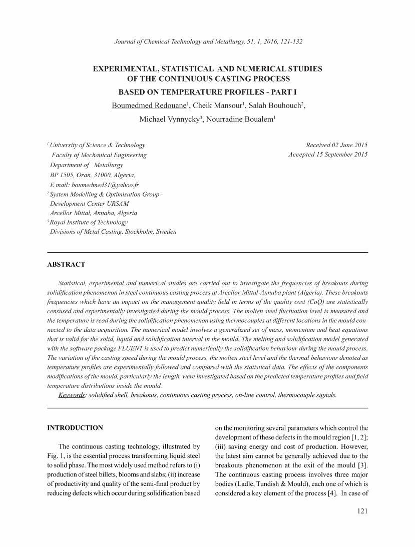
In case of casting using medium and small formats (< 1800 mm), thermocouples TC1-TC2-TC7-TC8 and thermocouples TC9-TC10-TC15-TC16 are not used, which is the case of this study. Fig. 3 shows the de-tailed geometry of the mould walls with the different thermocouples location at the wide and narrow faces. The dimensions of the mould used in this paper are men-tioned in Table 2.The experimental results referring to the casting speed evolution V(t) and the bath level evolu-
Fig. 2. Position of thermocouples in wide & narrow faces of mould.
Journal of Chemical Technology and Metallurgy, 51, 1, 2016
124
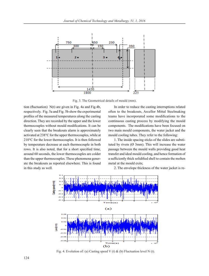
tion (fluctuation) N(t) are given in Fig. 4a and Fig.4b, respectively. Fig. 5a and Fig. 5b show the experimental profiles of the measured temperatures along the casting direction. They are recorded by the upper and the lower thermocouples without mould modifications. It can be clearly seen that the breakouts alarm is approximately activated at 238°C for the upper thermocouples, while at 210°C for the lower thermocouples. It is then followed by temperature decrease at each thermocouple in both rows. It is also noted, that for a short specified time, around 60 seconds, the lower thermocouples are colder than the upper thermocouples. These phenomena gener-ate the breakouts as reported elsewhere. This is found in this study as well.
In order to reduce the casting interruptions related often to the breakouts, Arcellor Mittal Steelmaking teams have incorporated some modifications to the continuous casting process by modifying the mould components. The modifications have been focused on two main mould components, the water jacket and the mould cooling tubes. They refer to the following:
1. The inside spacing sticks of the slides are substi-tuted by rivets (Ø 3mm). This will increase the water passage between the mould walls providing good heat transfer and ideal mould cooling, and hence formation of a sufficiently thick solidified shell to contain the molten metal at the mould exits;
2. The envelope thickness of the water jacket is re-
Fig. 4. Evolution of: (a) Casting speed V (t) & (b) Fluctuation level N (t).
Fig. 3. The Geometrical details of mould (mm).

Boumedmed Redouane, Cheik Mansour, Salah Bouhouch, Michael Vynnycky, Nourradine Boualem
125
inforced (6 mm) in order to avoid the mould distortions during casting and to ensure ideal heat transfer;
3. The steel grade of the water jacket is changed and stainless steel is used to avoid mould distortion and mould corrosion-erosion thus increasing the mould lifetime;
4. The inside cooling holes of the lower flange are substituted (Ø 10 mm) in order to rise the cooling wa-ter debit of the copper tube and provide an ideal water speed (6m s-1);
5. The mould length is extended in the lower side of the mould from L1 = 700 mm to L2 = 900 mm;
6. The coating layer thickness is reinforced (0.12 mm) to provide better protection of the inner copper
walls and hence to increase their lifetime to more than 400 casting taking into account the thermal conductivity.
The modifications described above have an efficient contribution from metallurgical and statistical perspec-tive, mainly in terms of the Cost of Quality (CoQ). Moreover, the temperature profiles recorded after the modifications incorporation are in good agreement with those statistically censused during this investigation.
It can be clearly seen from Fig. 6a and Fig. 6b that the temperature profiles of the measured temperatures along the casting direction, recorded by the upper and the lower thermocouples after the mould modifications, show constant stability and evolution continuity with time. It is worth adding that after the modifications
Fig. 6 (a). The temperature profiles at the upper thermo-couples with modifications.
Fig. 6 (b). The temperature profiles at the lower thermo-couples with modifications.
Fig. 5 (a). The temperature profiles at the upper thermo-couples (without modifications).
Fig. 5 (b). The temperature profiles at the lower thermo-couples (without modifications).

Journal of Chemical Technology and Metallurgy, 51, 1, 2016
126
introduction in 2012 the breakouts have decreased and even reached zero frequency, i.e. no perturbations related to the breakouts have been recorded. Thus it can be concluded that the experimental results are confirmed by those obtained by the statistical studies.
Statistical Study The data referring to the breakouts frequency are col-
lected from the second line of the first radial continuous casting machine. They are summarized in Table 3. Once the modifications of the water jacket and the mould cooling tubes have been introduced, the breakouts frequency rate decreased and has a value of zero since February 2013.
The breakouts problem has been solved but others arise. One of these is connected with the quality of the semi-final products which is affected because of hook and mark oscillation, most probably due to the mould oscillations, the consumption of lubrication or the flow behaviour inside the mould during the continuous cast-ing process. They all concern CoQ and which is why are considered a new challenge for the team engineers of ArcellorMittal-Annaba Steelmaking.
Model Description A 2D schematic diagram of the computational do-
main considered for the numerical simulation is shown
in Fig. 7. The steel chemical composition, the operating parameters and data concerning the mould geometry are given in Tables 1 and 2.
The Cartesian coordinates are designated by X and Z, the starting point is at Z = 0, the free surface of the mould has a symmetry axis line at X = 0, whence the mould wall is at X/2 from the symmetry axis. The super-heated liquid is at the homogeneous temperature Tcast > Tmelt and goes into the mould with homogeneous feed velocity at Z = 0. The molten steel and the solidi-fied shell are withdrawn at the exit of the mould at Z = L. Under steady operating conditions, the inlet velocity at the top of the mould (Z = 0) is linked to the casting speed. Thus, the mould is considered as a computational domain, taking into account the symmetry at X = 0. Consequently, the Gambit is employed in this study to mesh the computational domain (mush zone), as shown in Fig. 7. Although the continuous casting process is three-dimensional, we accept in this study a two dimen-sional configuration by introducing the 2D solidification and melting model using FLUENT package. The molten steel is poured continuously into the mould directly from the tundish. The liquid velocity at the inlet is assumed to be constant. Even if the FLUENT can solve fluid flow problems involving solidification, the turbulence in the liquid region during the solidification interval is not considered in this study. It is assumed that it appears inside the mould when steady state is established.
Instead of tracking explicitly the liquid-solid front, enthalpy porosity formulation is employed, where the
Fig. 7. A schematic view of the mould and Computational domain (mush zone).
C Mn Si P S Mo % 0,42 0,5 0.15 0,04 0,08 0,01
Table 1. Chemical composition of steel.
Operation & Mould Parameters Values
Liquidus Temperature 1774 K Solidus Temperature 1765 K Ladle Temperature 1830 ± 5 K Tundish Temperature 1757 ± 10 K Overheating Temperature 40 K Cooling Intensity 6.5 m3/h Casting speed 2.1 m/min Mould length (L) 700 - 900 mm Mould width (W) 130 mm Lubrication Powder
Table 2. Operating parameters and mould geometry.

Boumedmed Redouane, Cheik Mansour, Salah Bouhouch, Michael Vynnycky, Nourradine Boualem
127
liquid-solid mushy zone is simulated as a porous zone of porosity equal to that of the liquid function Besides appropriate sink terms are added to the momentum equation to account for the pressure drop caused by the presence of solid material. The liquid fraction, which indicates the fraction of the cell volume that is in a liquid form, is associated with each cell in the domain. Thus, the liquid fraction is computed at each iteration based on the enthalpy balance. The mushy zone, where the liquid fraction is within the range between 0 and 1, is modelled as a pseudo porous medium in which the porosity decreases from 1 to 0 as the molten steel solidi-fies. Once the melt is completely solidified in the cell, the porosity becomes zero and hence the velocities also drop to zero. Further procedural details can be found in the Fluent manual [27]. Thus the governing equations are:
Energy Equation The energy equation [27] can be presented in the
form:
( ) ( ) ( ) )1...(............ STKHvHt
+∇∇=∇+∂∂ ρρ (1)
where: H - enthalpy, ρ - density, V - fluid velocity, S - term source.
Here, the material enthalpy is computed as a sum of the sensible enthalpy, (h), and the latent heat, (ΔH)
)2..(..........HhH ∆+= (2)
where
ref
T
ref pT
h h C dT= + ∫ (3)
and Tref - reference temperature, href - reference enthalpy, Cp - specific heat at constant pressure.
An additional relation is added the equations above. It is referred to as a lever rule concerning the liquid fraction and the local temperature. However, the liquid fraction (β) can be defined as:
(4)
01
S
L L
SS L
L S
if T Tif T T
T T if T T TT T
β≤
= ≥−
≤ ≤−
where Tsol - soildus temperature, Tliq - liquidus temperature.The latent heat is written in terms of the material
latent heat (L):
)5.........(...........LH lβ=∆ (5)where β - liquid fraction, L - latent heat of material.
The latent heat content can vary between zero (for a solid) and L (for a liquid). The solution requires an interaction between the energy equation (Eq. 1) and the liquid fraction equation (Eq. 4). The direct application of Eq.(4) to update the liquid fraction usually results in poor convergence of the energy equation.
Momentum Equation The momentum equation can be written as follows:
( ) ( ). . . . . .( )leff c
p
v v v v v Skµρ ρ µ∇ ⊗ = −∇ +∇ ∇ + − +
(6)
where
( )Tleff µµµ +=
μeff includes the liquid molecular and turbulent viscosities μl and μT , respectively. In general terms, the mushy zone is modelled as a porous medium during solidification.
According to the enthalpy porosity formulation, the porosity in each cell is set equal to the liquid fraction in that cell. In fully solidified body region, the porosity is equal to zero, which extinguishes the velocities in these regions. The momentum due to the reduced porosity in the mushy zone takes the following form:
( )2
3
(1 ) .( )
Lm p
L
S A v vββ ε−
= −+
(7)
where βL- liquid fraction, ε - small number 0.001, Am - mushy zone, Vp - solid velocity. ε is introduced to prevent division by zero.
Years 2009 2010 2011 2012 2013 2014 2015 Frequency 10 12 17 40 00 00 00
Table 3. The frequencies of breakouts during the last six years.

Journal of Chemical Technology and Metallurgy, 51, 1, 2016
128
Continuity Equation The momentum equation can be presented in the form:
( ) )8...(....................0.. =∇ vρ (8)where ρ is the mixture density, while μ is the average mixture velocity. They are described by:
+
=
L
L
S
S
ρβ
ρβ
ρ 1
LLSS vvv .. ββ +=
where: βL and βs is the liquid and solid mass fraction, respectively, with (βL + βs) = 1, while (μL) is the liquid velocity and (μS) is the solid velocity.
RESULTS AND DISCUSSION
The finite element approximation of the two di-mensional solidification and melting model is solved by applying the enthalpy-porosity formulation, where the liquid-solid mushy zone is taken as porous zone with porosity equal to that of the liquid function.
In order to investigate numerically the breakouts frequency during the solidification, the two dimensional
Fig. 8. Temperature distribution inside the mould no modi-fied, Length = 700 mm and casting Speed = 2.1 m min-1 & cooling intensity = 6.5 m3 h-1.

Boumedmed Redouane, Cheik Mansour, Salah Bouhouch, Michael Vynnycky, Nourradine Boualem
129
model of solidification is applied to predict the tempera-ture distribution profile from the middle of the mould without modification (symmetry axis) to the surface of the walls having a length of 700 mm in case of casting speed and cooling intensity of VC = 2.1 m min-1 and IC
= 6.5 m3 h-1, respectively. This is illustrated in Fig. 8. The formation of cold zones close to the walls, the so called solidified shell is clearly seen. In fact it starts at the wall and reaches a certain thickness in X direction. This solidified shell is a subject of constraints which are most probably connected the breakouts origin. The numerical simulation of the temperature distribution profile in case of a modified mould of a length of 900 mm, casting speed VC = 2.1 m min-1 and cooling intensity IC = 6.5 m3 h-1 shows approximately the same interface arrangement in terms of numerical results. This is il-lustrated in Fig. 8.
The temperature curves and the predicted solidified shell thickness for a mould without and with modifica-tion of a casting geometry length of 700 mm and 900 mm, respectively, can be obtained through positioning of the temperature plots at different locations below the free surface of the mould (Z = 0). Figs. 9-11 visualize the temperature plots evolution at different positions in case of a mould without and with modified length of 700 mm and 900 mm, correspondingly, at a casting speed VC = 2.1 m min-1 and cooling intensity IC = 6.5 m3 h-1. Each figure shows a horizontal temperature profile below the free surface (Z = 0) at a given position X.
The steel melting point or the solidus temperature is 1765 K in our case (Table 1). Therefore, the steel above this temperature is still in the mushy zone where some of the material is in a solid state. Under the solidus tem-perature the material is solid. There the solidified shell formation begins to take form.
It can be noted that the temperature profiles of the modified mould are higher compared to those of the unmodified mould. However, the gaps between the tem-perature profiles of the modified and unmodified mould at each position are more important for the deep positions than the positions which are close to the meniscus and the free surface. This is not the case with the tempera-ture profiles at the meniscus position, where they are similar, because that position (Z0) is distinguished and considered as the first contact between the poured molten steel and the cooling water at the mould wall. The mushy zone starts to form there. It ranges between 1050 K and
1790 K. The temperature values remain constant in the mushy zone interval and above the melting point at this position in case of the modified and unmodified mould.
Fig. 9 illustrates the modifications effect applied to the mould. It shows clearly the emergence of the sensitive lag between the temperature profiles of the modified and unmodified mould at the position Z1, i.e. at 350 mm below the free surface. Thus, the temperature of the modified mould reaches the melting point giving form to the first nuclei of the solidified shell. The latter starts to grow in thickness close to the mould wall. The temperature profile of the unmodified mould v remains in the mushy zone interval.
Fig. 12. Profile of solidified shell thickness at various posi-tion surfaces, VC = 2.1 m min-1, IC = 6.5 m3 h-1.
Fig. 13. Cooling temperature profile inside the mould at (mushy zone interval).

Journal of Chemical Technology and Metallurgy, 51, 1, 2016
130
At position Z1, i.e. at 500 mm below the free sur-face, the lag between the temperature profiles becomes increasingly significant. Those of the unmodified mould reach also the melting point; consequently, the solidified shell starts to grow in thickness at the position Z2. But as Fig. 10 shows, the solidified shell of the modified becomes progressively thicker when compared to that of the unmodified mould. At the bottom the solidified shells of both moulds keep their thickness and form. However, that modified mould is thicker and stronger than that of the unmodified one, as seen in Fig. 11.
The present investigation shows that the modifica-tions applied to the mould process have a significant impact on the solidification. They control the horizontal locations of the solidification and the progression of the solidified shell. They contribute directly to CoQ by squarely eliminating the breakouts, as shown in Table 3. It is also seen that with those modifications the solidi-fication front moves downstream and the slope of the front becomes steeper. This makes the solidified shell strong enough to contain the molten steel at the exit of the mould.
The shell thicknesses of the solidified shell of both moulds at each position are given by Fig. 12. It is clearly seen that the solidified shell of the modified mould is much stronger than that of the unmodified mould. This most probably means that the solidified shell of the unmodified mould is not strong enough to contain the molten steel. There are maybe other factors influencing the mould process under the conditions considered. They refer to the heat transfer, the gap between the mould wall and the mould flux film, the lubrication layer.etc. On the other hand, it can be assumed that the operating conditions of the unmodified mould facilitate in fact the breakouts appearance. It is worth adding that the vertical temperature fields along the mould geometry are significantly influenced by the modifications intro-duced. The temperature profile of the modified mould is higher when compared that of the unmodified one. This is shown in Fig. 13.
As mentioned before, the temperature profiles and the slope of solidification front are very important for controlling the shell thickness of the solidified shell. The temperature fields, the location of the solidification front and the shell thickness may be controlled through mould modifications. The results presented here are of importance in obtaining better understanding of the
breakouts and the metallurgical equipments safety con-trol, thus safeguarding the continuous casting process. This leads to reduced cost of quality, improvement of the quality and productivity increase.
CONCLUSIONS
Modifications were designed and incorporated in the mould process in terms of casting geometry length and thermal behaviour. The temperature profiles of the modified and unmodified mould were recorded at differ-ent locations. A Fluent commercial package was used to analyse the data obtained. The solidification and melt-ing model based on enthalpy-porosity formulation was employed to investigate the effects of the modifications in terms of casting geometry length on the solidification behaviour. A statistical study of the breakouts frequency occurring in recent years was carried out. The main conclusions drawn from this investigation are as follows:
l The breakouts frequency rate decreased to zero after modifications incorporation;
l An efficient contribution was observed in terms of the metallurgical perspectives and cost of quality;
l The thermocouples temperature profiles were found stable with the mould modification;
l An increase of the horizontal and vertical tem-perature profiles found resulted in increase of the casting geometry length;
l The solidification moved forwards and became rigid with the increase of the casting geometry length;
l The solidified shell moved significantly forward (0.045 mm) with the increase of the casting geometry length.
The conclusions are drawn in case only the casting geometry length was considered during the two dimen-sional simulation. A three dimensional simulation is required for better modifications incorporation (mush in 3D) and comparability with the experiments. In sum-mary, the experimental and statistical results obtained substantiate that the operating conditions of the mould generate the breakouts and hence affect essentially the solidification proceeding. The application of the solidification and melting model based on the finite ele-ment method using FLUENT provides to simulate the solidification in a wide range of temperatures. It seems efficient and practical in terms of numeric perspectives. It can be used to investigate the effect of other operating

Boumedmed Redouane, Cheik Mansour, Salah Bouhouch, Michael Vynnycky, Nourradine Boualem
131
parameters (casting speed, cooling intensity, etc.) in the mould on the cost of quality.
Acknowledgements
The author wishes to thank the steelmaker workers and the engineers of the Arcellor Mittal - Annaba / Al-geria and the Center URSAM - CSC to have put at my disposal all necessary means. The first author is thankful to the remaining authors for giving all the explanations and the help needed for the success of this investigation.
REFERENCES
1. K.I. Miyazawa, Continuous casting of steel in Japan. Science & Technology of advanced material, 2, 1, 2001.
2. K.H.J. Buschow, R. Cahn, M. Flemings, B. Ilschner, E.J. Kramer, S. Mahajan, Continuous casting. (D. Apelian, subject Ed.), Elsevier Science Ltd., Oxford, v. 2, 2001, 1595-1599.
3. M. Kouhil, F. Farhi, Mould modification project, Arcellor Mittal Annaba, 2012.
4. Y. Sahai, E. Toshihiko, Chapter I, Tundish Technology for Clean Steel Production, World Scientific Publish-ing Co. Ltd. ISBN-13:978-9812706218, 2008.
5. N.A. McPherson, A. McLean, Continuous casting. Tundish to Mould transfer Operations. Iron and Steel. Society Warrendale, PA, ISS, v.6, 1992, p.1-29.
6. W. Kurz, About Initial Solidification in Continuous Casting of Steel, La Metallurgia Italiana, 2008, 56-64.
7. O. Legbus, J. Szekley, Interfacial phenomena and computational fluid mechanics in materials process-ing, ISIJ International, 34, 12, 1994.
8. J. Herbertson, Q.L. He, P.J. Flint, R.B. Mahapatra, Modelling of metal delivery to continuous casting mould, Steelmaking Conf. Proc., ISS, Warrendale, PA, (Washington, D.C.), v.74, 1991.
9. J. Kron, M. Bellet, A. Ludwig, B. Pustal, J. Wendt, H. Fredriksson, Comparison of numerical simulation models for predicting temperature in solidification analysis with reference to Air gap formation, Interna-tional Journal of Cast Metals Research, 17, 5, 2004.
10. C. Carlos, B. Roberto, A simple estimation method for shell thickness at the mold exit in the continuous casting of steel, ISIJ International, 41, 2001, 311-313.
11. J. Lait, J.K. Brimacombe, F. Weinberg, Mathemati-cal modelling of heat flow in the continuous casting Steel, Ironmaking Steelmaking, 2, 1974, 90-97.
12. B.G. Thomas, I.V. Samarasekera, J.K Brimacombe, Mathematical model of the thermal processing of steel ingots, Part II: Stress Model, Metall. Trans. B, 18B, 1987.
13. H.N. Han, A finite element model for 2-dimensional slice of cast strand, ISIJ International 39, 5, 1999.
14. I. Samarasekera, J.K. Brimacombe, Thermal and mechanical behaviour of continuous casting billet mold, Ironmaking & Steelmaking, 9, 1982.
15. J.E. Kelly, K.P. Michalek, T.G. O’Connor, B.G. Thomas, J.A. Dantzig, Initial development of thermal and stress fields in continuously cast Steel billets, Metall. Trans., 19A, 1988.
16. J. Barco, J. Palcio, C. Ojeda, O. Ojanguen, Modeli-zacion global del proceco de colada continua, Rev. Met., 41. Extra, 2005, 463-468.
17. J.E. Lee, H.N. Han, K.H. Oh, J.K Yoon, A fully cou-pled analysis of fluid flow, heat transfer and stress in continuous round billet casting, ISIJ International, 39, 5, 1999, 435-444.
18. C.H. Moon, S.M. Hwang, Analysis of flow, heat transfer, solidification, and inclusion removal in continuous slab caster by finite element method, Ironmaking & Steelmaking, 30, 2003, 48-56.
19. B.G. Thomas, A. Moitra, R. McDavid, Simulation of longitudinal off-corner depressions in continuously cast steel slabs, Ironmaking & Steelmaking, ISS Transactions, v. 23, 1996.
20. B.G. Thomas, G. Li, A. Moitra, D. Habing, Analy-sis of thermal and mechanical behavior of copper molds during continuous casting of steel slabs, 80th Steelmaking Conference Proceedings, Iron and Steel Society, 1997, 183-201.
21. E. Mizikar. Mathematical heat transfer model for solidification of continuously cast steel slabs, Aime. Met. Soc. Trans., 239, 11, 1967, 1747-1753.
22. M. Janik, H. Dyja, Modelling of three dimensional temperature fields inside the mould during continu-ous casting of steel, Journal of Materials Processing Technology, 2004, 157-158, 177-182.
23. Y. Meng, B.G. Thomas, Simulation of microstruc-ture and behavior of interfacial mold slag layers in continuous casting of steel, ISIJ International, 46, 5, 2006, 660-669.
Journal of Chemical Technology and Metallurgy, 51, 1, 2016
132
24. E. Pavel, R. Lopez, Explicit modelling of slag infiltration and shell formation during mould oscil-lation in continuous casting, ISIJ International, 50, 3, 2010, 425-343.
25. M. Alizadeh, J. Jahromi, Applying finite point method in solidification modelling during continu-ous casting process, ISIJ International, 50, 3, 2010.
26. J. Heger, Finite element modelling of mechanical phenomena connected to the technological process of continuous casting of steel, Acta Polytechnica, 44, 3, 2004.
27. ANSYS-FLUENT® Academic Research, Release 13.0, Help System, Solidification and Melting Guide, ANSYS, Inc.
28. E. Pavel, R. Lopez, Experimental validation and industrial application of a novel numerical model of continuous casting steel, Ninth International Confer-ence on CFD in the Minerals and Process Industries, CSIRO, Melbourne, Australia, 2012.
29. J. Aberg, M. Vynnycky, H. Fredriksson, Model-ling of thermal stresses in industrial continuous casting processes, Excerpt from the Proceedings of the COMSOL Multiphysics User’s Conference Stockholm, 2005.
30. J. Mahmoudi, M. Vynnycky, P. Sivesson, H. Fre-
driksson, An experimental and numerical study on the modelling of fluid flow, heat transfer and solidification in a copper continuous strip casting process, Material Trans., 44, 9, 2003.
31. D.T. Creech, B.G. Thomas, 3-D turbulent multiphase modelling of molten steel flow and heat transfer in a continuous slab caster, Presented at CFX User’s Conference, Wilmington, 1998.
32. B.G. Thomas, L. Zhang, Review: Mathematical Modeling of Fluid Flow in Continuous Casting, ISIJ International, 41, 10, 2001, 1181-1193.
33. J. Xin, R. Tingzhi, Breakout Prediction System Based on Combined Neural Network continuous casting, Advances in the Intelligent and Soft Computing, 168, 2012, 349-355.
34. X. Zening, M. Liangin, Study on Neural Network Breakout Prediction System Based on Temperature Unit Input, Measuring Technology and Mechatron-ics Automation (ICMTMA), International Confer-ence, v 3, 2012.
35. B.G. Zhang, L. Qiang, Breakout Prediction Based on BP Neural Network of LM Algorithm in Continuous Casting Process, Measuring Technology and Me-chatronics Automation (ICMTMA), International Conference, v.1, 2012.
![JOURNAL - dl.uctm.edu · New techniques that are currently being developed include capillary electrophoresis [13], immunoassays [14] and biosensors [15-18]. They potentially provide](https://static.fdocuments.net/doc/165x107/60297c90a85032002a6fb16e/journal-dluctmedu-new-techniques-that-are-currently-being-developed-include.jpg)