EXPERIMENTAL INVESTIGATION OF THE SHEAR MODULUS IN …
10
Peter Ficzere Lajos Borbas https://doi.org/10.21278/TOF.42103 ISSN 1333-1124 eISSN 1849-1391 EXPERIMENTAL INVESTIGATION OF THE SHEAR MODULUS IN THE CASE OF PURE TENSILE TEST Summary In this paper, the authors determine the shear modulus using a pure tensile test without the application of pure shear external load. In order to validate the computer-aided theoretical model, a measurement setup was designed and built by the authors. A theoretical model was realized by finite element model in order to simulate the torsion effect exerted by a pure shear mode. The authors have validated the theoretical and experimental results using a new and innovative photostress measurement. Key words: Rapid Prototyping; Orthotrophy; Photostress analysis; Shear stress determination 1. Introduction Using rapid prototypes, we can realize several concepts in a short time, which helps us to select the best one. It is very important to decrease the time to market, which is an advantage of rapid prototyping. In addition, using this method, arbitrarily complex geometries can be produced without tools. Additive production technologies have spread rapidly into the fields where the planning and manufacturing of individual tools would be too expensive; such as human prosthesis production [1], [2] and small series manufacturing. In such cases, we need to know whether the parts are suitable for carrying loads. To this end we usually need simulation. To what extent the parts can be loaded is basically determined by their material properties. Therefore, the selection of a proper material model for numerical simulation considerably influences its accuracy. Because of the OBJET Polyjet technology, where the acrylic-based photopolymer as the basic material polymerizes the drops by UV light, our assumption was that the material follows isotropic material law. Fig. 1 Specimens printed in different positions by OBJET Polyjet technology TRANSACTIONS OF FAMENA XLII-1 (2018) 27
Transcript of EXPERIMENTAL INVESTIGATION OF THE SHEAR MODULUS IN …

Peter Ficzere Lajos Borbas
https://doi.org/10.21278/TOF.42103 ISSN 1333-1124
eISSN 1849-1391
EXPERIMENTAL INVESTIGATION OF THE SHEAR MODULUS IN THE CASE OF PURE TENSILE TEST
Summary
In this paper, the authors determine the shear modulus using a pure tensile test without the application of pure shear external load. In order to validate the computer-aided theoretical model, a measurement setup was designed and built by the authors. A theoretical model was realized by finite element model in order to simulate the torsion effect exerted by a pure shear mode. The authors have validated the theoretical and experimental results using a new and innovative photostress measurement.
Key words: Rapid Prototyping; Orthotrophy; Photostress analysis; Shear stress determination
1. Introduction
Using rapid prototypes, we can realize several concepts in a short time, which helps us to select the best one. It is very important to decrease the time to market, which is an advantage of rapid prototyping. In addition, using this method, arbitrarily complex geometries can be produced without tools. Additive production technologies have spread rapidly into the fields where the planning and manufacturing of individual tools would be too expensive; such as human prosthesis production [1], [2] and small series manufacturing. In such cases, we need to know whether the parts are suitable for carrying loads. To this end we usually need simulation. To what extent the parts can be loaded is basically determined by their material properties. Therefore, the selection of a proper material model for numerical simulation considerably influences its accuracy. Because of the OBJET Polyjet technology, where the acrylic-based photopolymer as the basic material polymerizes the drops by UV light, our assumption was that the material follows isotropic material law.
Fig. 1 Specimens printed in different positions by OBJET Polyjet technology
TRANSACTIONS OF FAMENA XLII-1 (2018) 27

P. Ficzere, L. Borbas Experimental Investigation of the Shear Modulus in the Case of Pure Tensile Test
To decide whether the behaviour of this printed acrylic-based photopolymer follows the isotropic or the orthotropic material law, tensile tests have been carried out in three different printing directions also shown in Figure 1. The results of the tensile tests show that the materials of the rapid prototyping procedure prepared by the OBJET Polyjet technology do not behave in the isotropic way; thus, we have to be very careful when the material laws are used in the numerical analysis [3], [4], [5], [6]. In this technology, the same as in other additive technologies like Fused Deposition Modelling (FDM), we cannot use the isotropic material model [6]. Previously, we demonstrated that the model we had chosen can be described by the orthotropic material law. The orthotropic materials are special types of anisotropic materials. There are two or three principal directions, which have different material properties [7], [8]. The generalized Hooke law for orthotropic materials is
11 12 131 1
21 22 232 2
31 32 333 3
4423 23
5531 31
6612 12
0 0 00 0 00 0 0
0 0 0 0 00 0 0 0 00 0 0 0 0
S S SS S SS S S
SS
S
(1)
where are the strains in 1, 2, 3 directions, ij (ij) represents the engineering shear strain (i,j 1, 2, 3) are the normal stresses, ij (ij) are the shear stresses (i,j 1, 2, 3) Sij is the compliance matrix,
21 31
1 2 3
12 32
1 2 3
13 23
1 2 3
23
31
12
1 0 0 0
1 0 0 0
1 0 0 0
10 0 0 0 0
10 0 0 0 0
10 0 0 0 0
ij
E E E
E E E
E E ES
G
G
G
(2)
In the compliance matrix, E1, E2, E3 are the Young modulus. υij is Poisson’s ratio, that is the ratio of transverse strain in j-direction to longitudinal strain when stressed in i-direction (i,j 1, 2, 3) (ij) Gij are the shear moduli In addition: Sij=Sji
28 TRANSACTIONS OF FAMENA XLII-1 (2018)
Experimental Investigation of the Shear Modulus P. Ficzere, L. Borbas in the Case of Pure Tensile Test
In the isotropic case, the basic material properties can be specified by two independent material constants (E, υ).
E (3)
2(1 )EG
(4)
However, in the orthotropic case, the shear modulus (G) cannot be calculated using the constants mentioned above.
2. Methodology
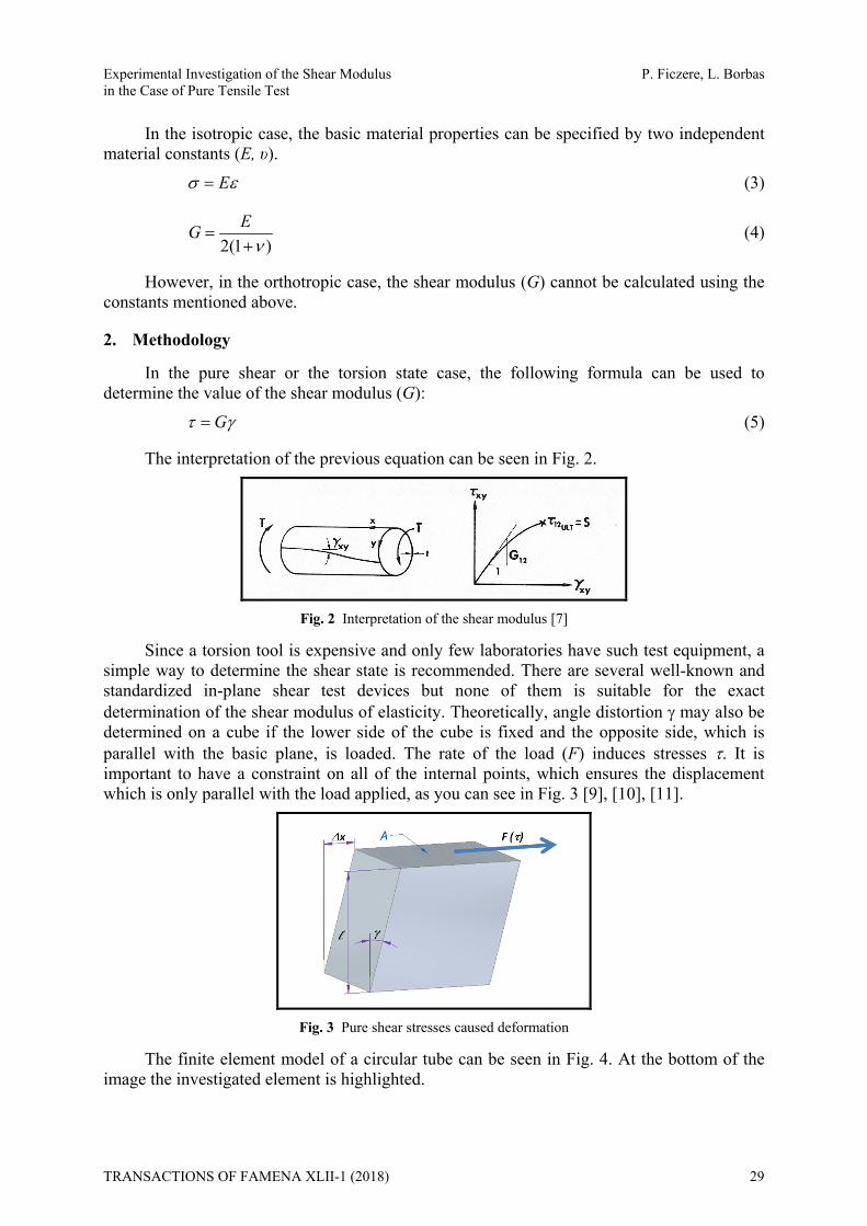
In the pure shear or the torsion state case, the following formula can be used to determine the value of the shear modulus (G):
G (5)
The interpretation of the previous equation can be seen in Fig. 2.
Fig. 2 Interpretation of the shear modulus [7]
Since a torsion tool is expensive and only few laboratories have such test equipment, a simple way to determine the shear state is recommended. There are several well-known and standardized in-plane shear test devices but none of them is suitable for the exact determination of the shear modulus of elasticity. Theoretically, angle distortion may also be determined on a cube if the lower side of the cube is fixed and the opposite side, which is parallel with the basic plane, is loaded. The rate of the load (F) induces stresses . It is important to have a constraint on all of the internal points, which ensures the displacement which is only parallel with the load applied, as you can see in Fig. 3 [9], [10], [11].
Fig. 3 Pure shear stresses caused deformation
The finite element model of a circular tube can be seen in Fig. 4. At the bottom of the image the investigated element is highlighted.
TRANSACTIONS OF FAMENA XLII-1 (2018) 29

P. Ficzere, L. Borbas Experimental Investigation of the Shear Modulus in the Case of Pure Tensile Test
Fig. 4 Finite element model of a circular tube
Figure 5 shows the deformation caused by torsion and a magnified element of the model which is highlighted.
Fig. 5 Deformation caused by torsion and a magnified element highlighted.
The same deformation caused by pure shear stresses can be seen on a prism in Fig. 6.
Fig. 6 Pure shear stresses on a prism cause deformation on the finite element model (displacements in the
direction parallel to the load direction)
Therefore, we had to develop a method which enables the determination of the shear modulus. The result is shown in Figure 7.
30 TRANSACTIONS OF FAMENA XLII-1 (2018)

Experimental Investigation of the Shear Modulus P. Ficzere, L. Borbas in the Case of Pure Tensile Test
Fig. 7 Layout of the clamping elements
The specimen is a 20x20x4 mm square-based prism made from the investigated acrylic-based photopolymer material. The specimen should be fixed to the clamping elements (Fig. 7). For that purpose, a special epoxy-based multicomponent glue (Type: Loctite Hysol 9466) was used.
3. Experimental results
Under real circumstances, the stress state determined by this method will not be pure shear stress, but it can be determined.
Fig. 8 The real stress state on the prism
Unfortunately, the implementation of the layout is impossible. The use of a clamping device requires perfectly coplanar surfaces, but it cannot be ensured. If the surfaces are not perfectly coplanar, the loads make the glue break off.
Fig. 9 Necessary condition to ensure the appropriate arrangement
For this reason, we had to develop a new layout of the clamping elements suitable for self-alignment. This layout is shown in Fig. 10.
TRANSACTIONS OF FAMENA XLII-1 (2018) 31

P. Ficzere, L. Borbas Experimental Investigation of the Shear Modulus in the Case of Pure Tensile Test
Fig. 10 Modified assembled layout
In this assembly, the pins ensure displacement perpendicular to the direction of the tensile load. Moreover, the stiffness of the clamping device decreases significantly. In this way, we had to determine the deformation of the clamping device to avoid false results. The characteristic of the clamping device depends on the applied load, which is shown in Figure 11. As one can see in the figure, the force elongation characteristic shows linear behaviour.
Fig. 11 Force elongation behaviour of the device
From the characteristics, we can calculate the deformation of the clamping device for all load cases.
In the next figure we can see the displacement of the clamping device and the specimen as well in the direction of the tensile load.
Fig. 12 Displacement of the clamping device
In Figure 12, the displacement of the clamping device is enlarged for better visibility on a scale of 40. The displacement can be seen on the colour bar. Values are in mm. As one can see, the clamping device exhibits a higher extent of deformation than the specimen itself and this fact cannot be ignored.
32 TRANSACTIONS OF FAMENA XLII-1 (2018)

Experimental Investigation of the Shear Modulus P. Ficzere, L. Borbas in the Case of Pure Tensile Test
Based on the measurement results, we can determine the shear modulus (G):
/ ( )m befG Fl A x x (6)
where is the shape factor of the specimen [-], F is the force load [N], l is the thickness of the specimen [mm], A is the loaded face area [mm2], xm is the measured displacement [mm], xbef is the displacement due to the deformation of the clamping device. The value of xbef is changing as a function of external loads. It is computable for a given load from the clamping device characteristic.
Thus, using this method, the shear modulus (G) can be determined by universal test equipment. The developed equipment can be seen in Fig. 13.
Fig. 13 Developed equipment for determination of the shear modulus
Figure 14 shows the theoretical and the real failure modes. The similarity can be seen clearly.
Fig. 14 Theoretical and the real failure modes
TRANSACTIONS OF FAMENA XLII-1 (2018) 33

P. Ficzere, L. Borbas Experimental Investigation of the Shear Modulus in the Case of Pure Tensile Test
To determine the material properties of rapid prototypes, tensile tests have been performed on standardized specimens in three different directions according to the built in orientations. These positions and the tensile test specimens are shown in Fig. 1.
The earlier experiments show that the material law is not isotropic but orthotropic. The Hooke law for materials following the orthotropic behaviour is more complicated than in the isotropic case. Earlier experiments could reduce the number of independent constants from nine to six because in some directions the material properties are the same [10].
The Poisson ratios (υ) were determined by tensile tests using the strain gauge measurement on specimens [10].
The shear modulus (G) was determined by an in-plane shear test method developed by the authors of this paper. It has to use correction factors which depend on the shape, the size, and the used materials.
The measured data were as follows:
Table 1 The measured values of the investigated material
E1=2350 MPa 12=0.39 G12=221 MPa
E2=2350 MPa 23=0.4465 G23=65 MPa
E3=2000 MPa 13=0.4465 G13=65 MPa
Each direction can be identified in the following figure:
Fig. 15 Principal directions of orthotropic material properties
After determining the material properties, they must be validated before the material is used. We checked our results by using a hybrid method [11]. The idea was to determine the strain distribution of a loaded element with complex geometry using the finite element method; subsequently, the results were validated on the same body by the photostress analysis. The investigated specimen was coated with a photoelastic material (thickness of the coating 1.2 mm, coating sensitivity 830 µstrain (10-6 mm/mm)) for the photostress analysis. The investigated part was loaded by an internal pressure. Based on the photostress law, the stress state of the investigated specimen has been determined by fringe pattern. The result of the photostress investigation has been compared with the results of the numerical simulation.
The finite element analysis and the photoelastic investigation produced the same results, as one can see in Figure 16 [12].
34 TRANSACTIONS OF FAMENA XLII-1 (2018)

Experimental Investigation of the Shear Modulus P. Ficzere, L. Borbas in the Case of Pure Tensile Test
Fig. 16 Results of the photoelastic investigation and numerical analysis (m=1 1-2=8.1MPa)
4. Conclusion
As a conclusion, we can state that the newly developed materials (composites, parts produced by additive production technology) show direction-dependent behaviour in several cases.
To describe the behaviour of these materials exactly, in addition to the basic material properties, the shear modulus has to be determined. This could be realised by a plane shear measurement or with a twisting device, which is a special and expensive machine.
In the case of standard shear investigation, the state is not a pure shear one, and the shear state changes during the shear process. Thus, the determination of the exact shear modulus is not possible in this way.
The newly developed instrument presented in this paper is suitable for the determination of the shear modulus with high accuracy. The results achieved by the instrumentation were validated by the photostress analysis.
5. Acknowledgements
These project results have been realized with a subsidy of the National Research Development and Innovation Office from the fund of NKIH. The title of the project is “Development of the New Generation of Production Technology for Individual Medical-Biological Implantation and Tools”. Project identification No.: NVKP_16-1-2016-0022. The elaborators express their thanks for the support.
REFERENCES [1] Petzold R., Zeilhofer H.-F., Kalender W.A., Rapid prototyping technology in medicine—basics and
applications, Computerized Medical Imaging and Graphics, 23(5), 1999, 277-284. https://doi.org/10.1016/S0895-6111(99)00025-7
[2] Győri M, Ficzere P.; Increasing Role of Sections Caused by 3D Modelling. PERIODICA POLYTECHNICA-TRANSPORTATION ENGINEERING 44:(3) pp. 164-171. (2016). https://doi.org/10.3311/PPtr.9053
[3] Martínez, J., Diéguez, J. L., Ares, E., Pereira, A., Hernández, P., & Pérez, J. A. Comparative between FEM models for FDM parts and their approach to a real mechanical behavior. Procedia Engineering, 63, (2013) 878-884. https://doi.org/10.1016/j.proeng.2013.08.230
[4] Ficzere P.; Borbás L.; Török Á.: Resource analysis of rapid prototyping, Production Improvement, Trnava: Tripsoft, (2011) pp. 160-172. (ISBN:978-80-89291-45-8)
[5] Jin, G. Q., Li, W. D., & Gao, L.. An adaptive process planning approach of rapid prototyping and manufacturing. Robotics and Computer-Integrated Manufacturing, 29(1), (2013) 23-38. https://doi.org/10.1016/j.rcim.2012.07.001
[6] Ficzere P.; Orthotrop anyagmodell alkalmazása additív gyártástechnológiával előállított alkatrész méretezése során [Usage of orthotropic material law for additive manufacturing in part design] GÉP LXVII:(5-6) pp. 78-81. (2016)
TRANSACTIONS OF FAMENA XLII-1 (2018) 35

P. Ficzere, L. Borbas Experimental Investigation of the Shear Modulus in the Case of Pure Tensile Test
[7] Jones R. M.: Mechanics of Composite Materials, SCRIPTA BOOK COMPANY, Washington, D.C., 1975, ISBN 0-07-032790-4
[8] Lovell M., Analysis of contact between transversely isotropic coated surfaces: development of stress and displacement relationships using FEM, Wear 214 (1998) 165-174. https://doi.org/10.1016/S0043-1648(97)00240-8
[9] Harth, P., Michelberger P. Development of a new method for planar-frame structure examination in commercial vehicle design, Periodica Polytechnika Transportation Engineering 42(1) (2014), 27-35. https://doi.org/10.3311/PPtr.7260
[10] Ficzere P., Borbás L.: Theoretical and Practical Analysis of Material Law Simplification Possibilities, 28th Danubia - Adria - Symposium on Advances in Experimental Mechanics. Siófok, Magyarország, 2011.09.28-2011.10.01. 2011. pp. 235-236. ISBN: 978-963-9058-32-3
[11] Ficzere P., Borbas L., Torok A: Validation of Numerically Simulated Rapid-prototype Model by Photoelastic Coating, ACTA MECHANICA SLOVACA 18:(1) pp. 14-24. (2014)
[12] Ficzere P, Borbás L.: Validation of Numerical Analysis Results in Case of Rapid Prototyping by Experiments Using Optical Techniques. In: 29th Danubia-Adria Symposium on advances in experimental mechanics. Beograd, Serbia, 2012.09.26-2012.09.28. Beograd: pp. 68-69. ISBN: 978-86-7083-762-1
Submitted: 14.7.2017 Accepted: 22.11.2017
Peter Ficzere Budapest University of Technology and Economics, Department of Vehicle Parts and Structures Analysis, H-1111, Budapest, Sztoczek u. 2.; [email protected] Lajos Borbas Budapest University of Technology and Economics, Department of Vehicle Parts and Structures Analysis; and EDUTUS College, Technical Institution, H-2800 Tatabánya, Stúdium tér. [email protected]
36 TRANSACTIONS OF FAMENA XLII-1 (2018)