Experimental Characterization of a Modified Airlift Pump
7
1 Current affiliation: University of Waterloo, 200 University Ave W, Waterloo, ON N2L 3G1, Canada, Email: [email protected]. EXPERIMENTAL CHARACTERIZATION OF A MODIFIED AIRLIFT PUMP Afshin Goharzadeh* Department of Mechanical Engineering The Petroleum Institute Abu Dhabi, U.A.E. *[email protected] Keegan Fernandes 1 Department of Mechanical Engineering The Petroleum Institute Abu Dhabi, U.A.E. ABSTRACT This paper presents an experimental investigation on a modified airlift pump. Experiments were undertaken as a function of air-water flow rate for two submergence ratios (=0.58 and 0.74), and two different riser geometries (i) straight pipe with a constant inner diameter of 19 mm and (ii) enlarged pipe with a sudden expanded diameter of 19 to 32 mm. These transparent vertical pipes, of 1 m length, were submerged in a transparent rectangular tank (0.45×0.45×1.1 m 3 ). The compressed air was injected into the vertical pipe to lift the water from the reservoir. The flow map regime is established for both configurations and compared with previous studies. The two phase air-water flow structure at the expansion region is experimentally characterized. Pipeline geometry is found to have a significant influence on the output water flow rate. Using high speed photography and electrical conductivity probes, new flow regimes, such as “slug to churn” and “annular to churn” flow, are observed and their influence on the output water flow rate and efficiency are discussed. These experimental results provide fundamental insights into the physics of modified airlift pump. INTRODUCTION Airlift pumps are widely used in the oil and gas industry for improving the efficiency of oil wells. Compressed air is used to transport liquid inside a vertical pipe. The injection of air from the bottom of the riser pipe generates bubbles which carry the liquid particles upward due to interfacial friction. The hydrodynamic properties of two-phase liquid- gas flow within the vertical riser pipe have been extensively reported over the last two decades [1-5]. Lawniczak et al. [1] studied the overall performance of airlift pumps and came to the conclusion that as the input air flow rate increases, the water flow rate increases until reaching a constant value. Additionally, they found that for low air flow rates the response water flow rate is linearly related, and that at higher air flow rates there is an exponential relation. Hanafizadeh et al. [2] studied the effects of flow regimes on the performance of airlift pumps. They used high speed camera to observe the flow of air and water traveling through the vertical transparent pipe. They classified four flow regimes, bubbly, slug, churn, and annular, with slug flow the most effective flow regime. Furthermore, they showed that as submergence ratio increases, the performance of the pump improves. Tighzert et al. [3] found that the maximum efficiency of an airlift pump occurs with slug flow, and soon falls during the transition from slug to churn flow. They also found that the optimal range for the pump is between a submergence ratio of 0.40 and 0.75. The effects of suction pipe diameter were studied by AlMaliky and AlAjawi [4]; they found that the pumping rate of the airlift pump increases as the suction diameter increases, due to the increase of static pressure and decrease of water velocity leading to lower friction losses. Kassab et al. [5] developed an analytical model to predict experimental results based on the relation between water and air flow rates provided by Stenning and Proceedings of the ASME 2014 International Mechanical Engineering Congress and Exposition IMECE2014 November 14-20, 2014, Montreal, Quebec, Canada IMECE2014-39899 1 Copyright © 2014 by ASME
Transcript of Experimental Characterization of a Modified Airlift Pump

1Current affiliation: University of Waterloo, 200 University Ave W, Waterloo, ON N2L 3G1, Canada, Email: [email protected].
EXPERIMENTAL CHARACTERIZATION OF A MODIFIED AIRLIFT PUMP
Afshin Goharzadeh* Department of Mechanical Engineering
The Petroleum Institute Abu Dhabi, U.A.E.
Keegan Fernandes1 Department of Mechanical Engineering
The Petroleum Institute Abu Dhabi, U.A.E.
ABSTRACT
This paper presents an experimental investigation
on a modified airlift pump. Experiments were
undertaken as a function of air-water flow rate for two
submergence ratios (=0.58 and 0.74), and two
different riser geometries (i) straight pipe with a
constant inner diameter of 19 mm and (ii) enlarged
pipe with a sudden expanded diameter of 19 to 32 mm.
These transparent vertical pipes, of 1 m length, were
submerged in a transparent rectangular tank
(0.45×0.45×1.1 m3). The compressed air was injected
into the vertical pipe to lift the water from the
reservoir. The flow map regime is established for both
configurations and compared with previous studies.
The two phase air-water flow structure at the expansion
region is experimentally characterized. Pipeline
geometry is found to have a significant influence on the
output water flow rate. Using high speed photography
and electrical conductivity probes, new flow regimes,
such as “slug to churn” and “annular to churn” flow,
are observed and their influence on the output water
flow rate and efficiency are discussed. These
experimental results provide fundamental insights into
the physics of modified airlift pump.
INTRODUCTION
Airlift pumps are widely used in the oil and gas
industry for improving the efficiency of oil wells.
Compressed air is used to transport liquid inside a
vertical pipe. The injection of air from the bottom of
the riser pipe generates bubbles which carry the liquid
particles upward due to interfacial friction.
The hydrodynamic properties of two-phase liquid-
gas flow within the vertical riser pipe have been
extensively reported over the last two decades [1-5].
Lawniczak et al. [1] studied the overall performance of
airlift pumps and came to the conclusion that as the
input air flow rate increases, the water flow rate
increases until reaching a constant value. Additionally,
they found that for low air flow rates the response
water flow rate is linearly related, and that at higher air
flow rates there is an exponential relation. Hanafizadeh
et al. [2] studied the effects of flow regimes on the
performance of airlift pumps. They used high speed
camera to observe the flow of air and water traveling
through the vertical transparent pipe. They classified
four flow regimes, bubbly, slug, churn, and annular,
with slug flow the most effective flow regime.
Furthermore, they showed that as submergence ratio
increases, the performance of the pump improves.
Tighzert et al. [3] found that the maximum efficiency
of an airlift pump occurs with slug flow, and soon falls
during the transition from slug to churn flow. They also
found that the optimal range for the pump is between a
submergence ratio of 0.40 and 0.75. The effects of
suction pipe diameter were studied by AlMaliky and
AlAjawi [4]; they found that the pumping rate of the
airlift pump increases as the suction diameter increases,
due to the increase of static pressure and decrease of
water velocity leading to lower friction losses. Kassab
et al. [5] developed an analytical model to predict
experimental results based on the relation between
water and air flow rates provided by Stenning and
Proceedings of the ASME 2014 International Mechanical Engineering Congress and Exposition IMECE2014
November 14-20, 2014, Montreal, Quebec, Canada
IMECE2014-39899
1 Copyright © 2014 by ASME
Martin [6]. Mahrous [7-10] developed models for the
study of air injection types, single stage versus multi
stage [7], as well as for airlift pumps with a bent riser
[8], solid particles [9] or gradually enlarged segment in
the riser tube [10]. Similarly, Hanafizadeh et al. [11]
developed a numerical model to study the effect of step
geometry in the riser pipe, where they found that a
sudden increase in diameter can increase the efficiency
and the water flow rate. Weismann [12] established the
flow regime map for air-water in a 25 mm vertical pipe
and Nicklin [13] developed and analytical equation for
efficiency. The effect of air injection, tube diameter,
submergence ratio and riser inclination were also
investigated experimentally [14-20]. However, the experimental studies of liquid-gas
flows for the geometric case of the sudden expansion
of the riser inner pipe diameter have not been
extensively assessed. Hence, the purpose of this study
is to characterize experimentally the influence of the
sudden expansion on both water flow rates and
efficiency of the airlift pump as well as to observe the
effect of flow regimes on the output water flow rate.
The paper is structured as follows. The
experimental setup and the flow visualization system
employed are described. Measurements of the
superficial velocities are presented. The influence of
sudden expansion on two-phase water-air flow regime
map is discussed. The flow rate performance curve and
the efficiency are measured and presented for different
geometries and submergence ratios.
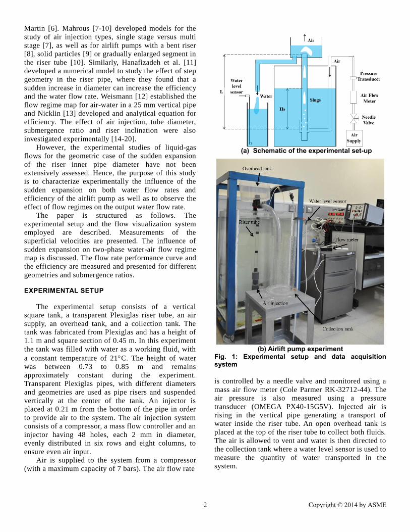
EXPERIMENTAL SETUP
The experimental setup consists of a vertical
square tank, a transparent Plexiglas riser tube, an air
supply, an overhead tank, and a collection tank. The
tank was fabricated from Plexiglas and has a height of
1.1 m and square section of 0.45 m. In this experiment
the tank was filled with water as a working fluid, with
a constant temperature of 21C. The height of water
was between 0.73 to 0.85 m and remains
approximately constant during the experiment.
Transparent Plexiglas pipes, with different diameters
and geometries are used as pipe risers and suspended
vertically at the center of the tank. An injector is
placed at 0.21 m from the bottom of the pipe in order
to provide air to the system. The air injection system
consists of a compressor, a mass flow controller and an
injector having 48 holes, each 2 mm in diameter,
evenly distributed in six rows and eight columns, to
ensure even air input.
Air is supplied to the system from a compressor
(with a maximum capacity of 7 bars). The air flow rate
is controlled by a needle valve and monitored using a
mass air flow meter (Cole Parmer RK-32712-44). The
air pressure is also measured using a pressure
transducer (OMEGA PX40-15G5V). Injected air is
rising in the vertical pipe generating a transport of
water inside the riser tube. An open overhead tank is
placed at the top of the riser tube to collect both fluids.
The air is allowed to vent and water is then directed to
the collection tank where a water level sensor is used to
measure the quantity of water transported in the
system.
(a) Schematic of the experimental set-up
(b) Airlift pump experiment
Fig. 1: Experimental setup and data acquisition system
2 Copyright © 2014 by ASME
Submergence ratio is defined as: 𝜀 =𝐻
𝐿, where 𝐻𝑠
is the height of the water above the air injection area
(Fig. 1.a) and 𝐿 is the length of the riser tube. The
submergence ratio is altered by adjusting the level of
water in the tank.
Experiments were conducted for two different
pipe configurations reported in Table 1. Riser pipe 1
has a constant inner diameter along the vertical axis,
D=19 mm. The inner diameter of the riser pipe 2
increases suddenly at L=0.4 m from the air injector.
The inner diameter of this pipe before the expansion
area is 19 mm and 32 mm after the expansion. All
pipes have 1 m length and consist of a 0.2 m suction
segment and a 0.8 m riser segment. All experiments
were undertaken with two different submergence
ratios of 0.58 and 0.74 and using several different air
flow rates from 0.04×10⁻³
m3/s to 1.6×10
-3 m
3/s.
Table 1 Characteristics of pipe geometry Riser pipe Type Inner diameter (mm)
1 Straight 19
2 Expanded 19 to 32
The two phase air-water flow was examined using
a high speed camera. To illuminate the central area of
the tank, a lamp was installed at the right side of the
tank and a high speed camera (Photron FASTCAM
SA3) was installed perpendicular to the vertical wall
of the tank at the distance of 0.70 m. Full-frame
images of 1024 × 1024 pixels were acquired and
transferred to a computer via a frame grabber. The
measurements were focused on the center of the riser
pipes.
Measurements Uncertainty
The key parameters contributing to the
measurements uncertainty were mass flow rates, water
level, time and pressure. Air flow rate measurement
was obtained using Cole Parmer gas mass flow meter
(RK-32712-44). The estimated error, provided from
the supplier in mass flow measurement was 2% of full
scale. For water flow rates, the sensor level is used to
measure the height of water displaced by the airlift
pump for a certain period of time. The error in the
determination of the water flow rate including the
level sensor and time measurements was
approximately 7%. The pressure measurements was
obtained using as pressure transducer (OMEGA
PX40-15G5V) having a measurement uncertainty of
±0.15% full scale.
RESULTS
Test Facility Validation
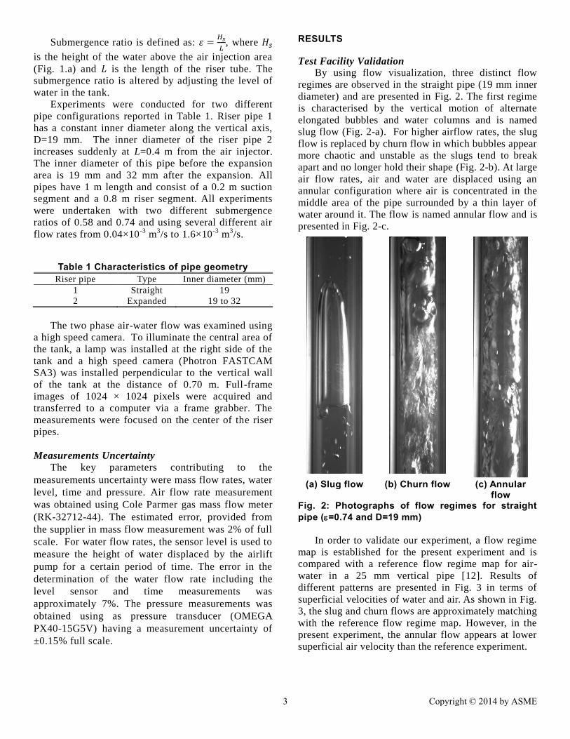
By using flow visualization, three distinct flow
regimes are observed in the straight pipe (19 mm inner
diameter) and are presented in Fig. 2. The first regime
is characterised by the vertical motion of alternate
elongated bubbles and water columns and is named
slug flow (Fig. 2-a). For higher airflow rates, the slug
flow is replaced by churn flow in which bubbles appear
more chaotic and unstable as the slugs tend to break
apart and no longer hold their shape (Fig. 2-b). At large
air flow rates, air and water are displaced using an
annular configuration where air is concentrated in the
middle area of the pipe surrounded by a thin layer of
water around it. The flow is named annular flow and is
presented in Fig. 2-c.
In order to validate our experiment, a flow regime
map is established for the present experiment and is
compared with a reference flow regime map for air-
water in a 25 mm vertical pipe [12]. Results of
different patterns are presented in Fig. 3 in terms of
superficial velocities of water and air. As shown in Fig.
3, the slug and churn flows are approximately matching
with the reference flow regime map. However, in the
present experiment, the annular flow appears at lower
superficial air velocity than the reference experiment.
(a) Slug flow (b) Churn flow (c) Annular
flow Fig. 2: Photographs of flow regimes for straight pipe (=0.74 and D=19 mm)
3 Copyright © 2014 by ASME

This discrepancy can be mainly attributed to the
difference of inner pipe diameter (19 mm diameter in
the present experiment compared to 25 mm in
Weisman’s [12] experiment). This smaller diameter
could cause bubbles to coalesce much faster causing
slug and annular flow to occur more rapidly or at
lower velocities. Another potential cause for this
difference could be that the experiment done in this
study took place in a submerged environment versus
Weismann’s experiment [12] which was performed in
a long vertical pipe where two phase water-air flow
was generated using a water pump and air compressor.
Influence of an expanded inner pipe diameter on flow
patterns
The comparisons of flow regimes between different
pipe configurations (straight and expanded) are presented
in Fig. 4. It was observed that all three flow regimes (slug,
churn and annular) exist in both straight and expanded
pipes. However, the expanded pipe influences the
characteristics of these flow regimes, particularly at the
critical flow rates where the flow regime is expected to
change in a straight pipe.
For the riser pipe 2, the sudden expansion of the inner
diameter from 19 mm to 32 mm, increases the turbulence
of pipe flow in this expanded area. This transition causes
two additional flow regimes to form:
(i) Slug to Churn Flow: characterized by a co-existence
of slug flow and churn flow. Slug bubbles passing through
the expansion area are disrupted and break apart forming
churn flow (Fig. 5.a).
Fig. 4: Measured flow regimes of air/water mixture in vertical expanded and straight pipes for the current test facility (=0.74).
(a) Slug to
churn (b) Churn to
churn (c) Annular to
churn Fig. 5: Photographs of flow regimes for expanded pipe (=0.74 and D=19-32 mm)
(ii) Annular to Churn Flow: characterized by a
co-existence of annular and churn flow. Annular flow
which represents a stable regime is disturbed when it
passes through the expansion area forming a more
chaotic regime of churn flow (Fig. 5-c).
It is important to notice that far from the critical
flow rates where the flow regimes map changes for
the straight pipes, it possible to obtain slug to slug as
well as churn to churn (Fig. 5-b) and annular to
annular flow regimes.
Dashed lines and points are experimental data provided from the current study while the hatched zones represent the experimental predictions of Weisman [12].
Fig. 3: Comparison of measured flow regimes of air/water mixture in vertical riser pipes for the current test facility with the reference data
4 Copyright © 2014 by ASME

Influence of an expanded inner pipe diameter on
flow rate performance curve
Fig. 6 shows the flow rate performance
comparison between the straight and expanded pipes.
The water flow rates increase and depend strongly on
air flow rates. For the case of a straight pipe
(D=19mm), for both submergence ratios =0.58 and
0.74), flow rate performance curves can be divided to
two parts (i) at low air flow rates 0<Qg<0.2 ×10⁻³
m3/s, Qw increases drastically with Qg, corresponding
to slug and churn flow regimes, (ii) for Qg>0.2 ×10⁻³
m3/s water flow rates increase slowly until reaching
constant value corresponding to the case of annular
flow regimes in the pipe.
Fig. 6: Flow rate performance curve of the airlift pump for different submergence ratio and geometry
Regarding expanded pipes, at low air flow rates
0<Qg<0.2×10⁻³
m3/s, Qw increases with Qg, with lower
values than the case of straight pipes. The flow rate
performance curve of expanded pipes, increases
continuously with Qg until crossing a critical point
where the curve of the straight pipe reaches a constant
value. It is observed that the straight pipe has a better
output water flow rate at lower air flow rates.
However, at flow rates above a critical point, which
varies for different pipe parameters, the expanded
pipe has the higher output water flow rate.
This could be explained by the additional flow
regimes observed in the expanded pipe (Fig. 4 & 5). It
has been shown that slug flow is more desirable than
churn flow and churn flow more desirable than
annular flow [2-3]. Therefore, it could be assumed
that the expanded pipe has a lower output rate at low
air flow rates. This is due to its ability to have a slug
to churn regime, as this would cause the more
efficient slugs to be broken down into churn and so
lowers the output rate. The other difference in output
rate could be due to the fact that the expanded area
breaks down long slugs to multiple small slugs, which
have less buoyant force to lift up water. Similarly, the
higher output rate of expanded pipes, for high air flow
rates, could be attributed to the annular to churn flow
regime, as the less efficient annular flow is converted
into churn flow.
Influence of an expanded inner pipe diameter on
efficiency of the airlift pump
The efficiency of the airlift pump for different
submergence ratios and pipe geometries are presented
in Fig. 7. The equation used to calculate efficiency is
given by Nicklin [13]:
𝜂 =𝜌𝑔𝑄𝑤(𝐿 − 𝐻𝑠)
𝑃𝑎𝑄𝑔𝐿𝑛𝑃𝑖𝑛𝑃𝑎
Eq.1
where 𝜂 is the efficiency, 𝜌 is the liquid density in
kg/m3, 𝑔 is the gravitational acceleration in m/s
2, 𝑄𝑤
and 𝑄𝑔 are the water and air discharge rate
respectively, both in m3/s, 𝐿 is the length of the riser
pipe in m, 𝐻𝑠 is the height of the pipe that is
submerged in m, 𝑃𝑎 is the atmospheric pressure in
N/m2, and 𝑃𝑖𝑛 is the pressure at the injection point in
N/m2.
It is observed that all curves have a maximum
efficiency corresponding to a drastic increase at low
air flow rates 0<Qg<0.4×10⁻³
m3/s and smooth
decrease after the maximum point, where the air flow
rate increases. This trend is comparable to previous
experimental results [1-5]. It is important to notice
that the geometry of the pipe affects significantly the
maximum efficiency point of the airlift pump. The
efficiency of the expanded pipe is lower compared to
that of straight pipes for low flow rates
(0<Qg<0.4×10⁻³
m3/s).
For higher flow rates (Qg>0.4×10⁻³
m3/s) the
geometry of the pipes and submergence ratio do not
significantly affect the efficiency of the airlift pump.
The large difference in efficiency for the lower flow
rates can be attributed to equation 1.
From this equation it is noticed that only three
variables can affect the system, (i) the injection
pressure (𝑃𝑖𝑛), (ii) the water flowrate (𝑄𝑤 ) and (iii)
the air flow rate (𝑄𝑔). The ratio of injection pressure
to atmospheric pressure is close to one for all cases.
Therefore, the efficiency is significantly affected by
5 Copyright © 2014 by ASME

Fig. 7: Efficiency curve of the airlift pump for different submergence ratio and geometry
the ratio of flow rates, as seen in the equation
provided. From Fig. 6 it can be seen that this ratio has
a notably high value at low air flow rates
(0<Qg<0.4×10⁻³
m3/s) and the ratio converges to a
constant value for high flow rates. Consequently, the
influence of geometry cannot be observed on the
efficiency for higher flow rates (Qg>0.4×10⁻³
m3/s).
CONCLUSIONS
In this study, the influence of an expanded inner
diameter of riser pipe on the airlift pump is
investigated. Experiments were undertaken as a
function of air-water flow rate for two submergence
ratios (=0.58 and 0.74), and two different riser
geometries (i) straight pipe with a constant inner
diameter of 19 mm and (ii) enlarged pipe with sudden
inward expanded diameter of 19 to 32 mm. The flow
map regime is established for both configuration and
compared with previous studies. For the straight pipe,
the flow regime map of slug and churn flows
approximately match the reference flow regime map
[12]. For the expanded pipe, new flow regimes, such
as “slug to churn” and “annular to churn” flow, are
observed and their influence on the output water flow
rate and efficiency are discussed. Based on the
visualized air-water flow, pipeline geometry is found
to have a significant influence on the output water
flow rate. The influence of both submergence ratio
and geometry are negligible on the efficiency for high
flow rates. Future experimental analysis related to
gradual expansion will be conducted to complete this
study.
REFERENCES
[1] Lawniczak, F., Francois, P., Scrivener, O.,
Kastrinakis, E. G., and Nychas, S. G., 1999, “The
Efficiency of Short Airlift Pumps Operating at Low
Submergence Ratios,” Can. J. Chem. Eng., 77(1),
pp. 3-10.
[2] Hanafizadeh, P., Ghanbarzadeh, S., and Saidi, M.,
2011, “Visual Technique for Detection of Gas–
Liquid Two-Phase Flow Regime in the Airlift
Pump,” J. Petrol. Sci. and Eng., 75(3-4), pp. 327-
335.
[3] Tighzert, H., Brahimi, M., Kechroud, N., and
Benabbas, F., 2013, “Effect of Submergence Ratio
on the Liquid Phase Velocity, Efficiency and Void
Fraction in an Air-Lift Pump,” Journal of Petroleum
Science and Engineering, 110, pp. 155-161.
[4] AlMaliky, S. J., and AlAjawi, H. A., 2009, “Effect of
Suction Pipe Diameter and Submergence Ratio on
Air Lift Pumping Rate,” Tikrit Journal of
Engineering Sciences, 16(1), pp.63-73.
[5] Kassab, S., Kandil, H., Warda, H., and Ahmad, W.,
2009, “Air-Lift Pumps Characteristics under Two-
Phase Flow Conditions,” Int. J. Heat Fluid Fl.,
30(1), pp. 88-98.
[6] Stenning, A. H., and Martin, C. B., 1968, “An
Analytical and Experimental Study of Air-Lift Pump
Performance,” J. Eng. Gas Turbines Power, 90(2),
pp. 106-110.
[7] Mahrous, A. –F., 2014, “Performance of Airlift
Pumps: Single-Stage vs. Multistage Air Injection,”
American Journal of Mechanical Engineering, 2(1),
pp. 28-33.
[8] Mahrous, A. –F., 2013, “Performance Study of an
Airlift Pump with Bent Riser Tube,” WSEAS
Transactions on Applied and Theoretical Mechanics,
8(2), pp. 136-145.
[9] Mahrous, A. –F., 2012, “Numerical Study of Solid
Particles-Based Airlift Pump Performance WSEAS
Transactions on Applied and Theoretical Mechanics,
7(3), pp. 221-230.
[10] Mahrous, A. –F., 2013, “Airlift Pump with a
Gradually Enlarged Segment in the Riser Tube,” J.
Fluids Eng., 135(3), pp. 031301.
[11] Hanafizadeh, P., Karimi, A., and Saidi, M. H., 2011,
“Effect of Step Geometry on the Performance of the
Airlift Pump,” International Journal of Fluid
Mechanics Research, 38(5), pp. 387-408.
[12] Weisman, J., 1983, Handbook of Fluids in Motion,
Ann Arbor Science, Ann Arbor, MI, pp. 409-425
6 Copyright © 2014 by ASME

[13] Nicklin, D.J., 1963, “The Air Lift Pump Theory and
Optimization,” Trans. Inst. Chem. Eng. 41, pp. 29–
39
[14] Hu, D., Tang, C. –L., Cai, S. –P., and Zhang, F. –H.,
2012, “The Effect of Air Injection Method on the
Airlift Pump Performance,” ASME J. Fluids Eng.,
134(11), pp. 111302.
[15] Kim, S., Sohn, and C., Hwang, J., 2014, “Effects of
Tube Diameter and Submergence Ratio on Bubble
Pattern and Performance of Air-Lift Pump,” Int. J.
Multiphase Flow, 58, pp. 195-204.
[16] Esen, I. I., 2010, “Experimental Investigation of a
Rectangular Airlift Pump,” Advances in Civil
Engineering, 2010, pp. 789547.
[17] Kassab, S., Z., Kandil, H., A., Warda, H., A., and
Ahmed, W., H., 2007, “Experimental and Analytical
Investigation of Airlift Pumps Operating in Three-
Phase Flow,” Chem. Eng. J., 131(1-3), pp. 3-10.
[18] Weisman, J., and Kang, S., Y., 1981, 271-291,
“Flow Pattern Transitions in Vertical and Upwardly
Inclined Lines,” Int. J. Multiphase Flow, 7(3), pp.
271-291.
[19] McQuillan, K., Q., 1985, “Flow Patterns in Vertical
Two-Phase Flow,” Int. J. Multiphase Flow, 11(2),
pp. 161-175.
[20] Kaichiro, M., 1984, “Flow Regime Transition
Criteria for Upward Two-Phase Flow in Vertical
Tubes,” Int. J. Heat Mass Tran., 27(5), pp. 723-737.
7 Copyright © 2014 by ASME