EXPERIMENTAL ANALYSIS ON WATER PIPE TURBINE …umpir.ump.edu.my/id/eprint/8526/1/CD8074_@_51.pdf ·...
24
EXPERIMENTAL ANALYSIS ON WATER PIPE TURBINE-GENERATOR DESIGN PARAMETERS NURULAMNI BINTI MD MUKHTAR Report submitted in partial fulfillment of the requirements for the award of the degree of Bachelor of Mechanical Engineering Faculty of Mechanical Engineering UNIVERSITI MALAYSIA PAHANG JUNE 2013
Transcript of EXPERIMENTAL ANALYSIS ON WATER PIPE TURBINE …umpir.ump.edu.my/id/eprint/8526/1/CD8074_@_51.pdf ·...
EXPERIMENTAL ANALYSIS ON WATER PIPE TURBINE-GENERATOR
DESIGN PARAMETERS
NURULAMNI BINTI MD MUKHTAR
Report submitted in partial fulfillment of the
requirements for the award of the degree of
Bachelor of Mechanical Engineering
Faculty of Mechanical Engineering
UNIVERSITI MALAYSIA PAHANG
JUNE 2013

vi
ABSTRACT
The objective of the study is to develop a small-scale water pump based test bed and to
do prototyping of various turbine designs based on various parameters. As the energy
demand of industry grows exponentially, fabrication of hydraulic energy system
becomes a crucial point of concern. Many research activities about hydraulic have been
carried out by experimental methods and by theory and simulation. Hydro energy
parameters have been used to study the relation between the hydro energy parameters
and subsequent relative output energy. The results obtained by the experimental results,
performed in prototype model. In this work different parameters have been used to tap
water. The water injected by nozzle on blades of hydraulic turbines. Efficiency and
maximal power output are two of the most important goals to analyze in hydraulic
turbines. The efficiency of water turbines are most frequently expressed using the power
output at the alternator. To perform the calculation of efficiency is necessary to know
several parameters such as kinetic and potential energy of water due to the position,
because of this is required to know the flow rate entering the turbine. The flow rate of
water through the turbine (Q) is determined by the volume of water flowing in time
unit. As a conclusion, this project is quite successful because it is able to fulfill all of the
objectives stated and also performing up to expectation.

vii
ABSTRAK
Objektif kajian adalah untuk membentuk sebuah pam air berasaskan ujian kecil-kecilan
dan untuk melakukan prototaip daripada pelbagai reka bentuk turbin berdasarkan
pelbagai parameter. Sebagaimana permintaan tenaga industri tumbuh dengan pesat,
pembikinan sistem tenaga hidraulik merupakan hal penting yang membimbangkan.
Banyak aktiviti-aktiviti penyelidikan mengenai hidraulik telah dijalankan dengan
kaedah eksperimen dan teori dan simulasi. Parameter tenaga hidro telah digunakan
untuk mengkaji hubungan antara parameter tenaga hidro dan seterusnya tenaga output
relatif. Keputusan yang diperolehi oleh keputusan eksperimen telah dilakukan dalam
model prototaip Dalam eksperimen ini, parameter yang berbeza telah digunakan untuk
air paip. Air disuntik oleh muncung pada bilah turbin hidraulik. Kecekapan dan output
kuasa maksimum adalah dua matlamat yang paling penting untuk menganalisis dalam
turbin hidraulik. Kecekapan turbin air yang paling kerap dinyatakan menggunakan
output kuasa pada alternator. Untuk melakukan pengiraan kecekapan adalah penting
untuk mengetahui beberapa parameter seperti tenaga kinetik dan potensi air kerana
kedudukannya, kerana ini diperlukan untuk mengetahui kadar aliran yang memasuki
turbin. Kadar aliran air melalui turbin (Q) adalah ditentukan oleh jumlah air yang
mengalir di dalam unit masa. Kesimpulannya, projek ini amatlah berjaya kerana semua
objektif berjaya dicapai dan mesin prototaip yang terhasil berfungsi pada tahap yang
memuaskan.

viii
TABLE OF CONTENTS
PAGE
SUPERVISOR'S DECLARATION
ii
STUDENT'S DECLARATION
iii
ACKNOWLEDGEMENTS
v
ABSTRACT
vi
ABSTRAK
vii
TABLE OF CONTENTS
viii
LIST OF TABLE
xi
LIST OF FIGURE
xii
LIST OF SYMBOLS
xiv
LIST OF ABBREVIATIONS
xv
CHAPTER 1 INTRODUCTION
1.1
Background Study
1
1.2 Problem Statement
1
1.3 Objectives
2
1.4 Scopes
2
1.5 Hypothesis
2
1.6 Flow Chart
3
1.7 Gantt Chart
3
CHAPTER 2 LITERATURE REVIEW
2. 0
Introduction
4
2.1 Advantages of Hydropower
4
2.2 Hydroturbines
4
2.3 Parameters of Hydroturbines
7
2.3.1 Head
7
2.3.2 Flow Rate
7
2.3.3 Power and Energy
7
2.4 Turbine Efficiency
8

ix
2.5 Pico-Hydro Power Generation Case Study
9
2.5.1 Peltric Set
9
2.5.2 Columbian Alternator System
10
2.5.3 Pico Power Pack
10
2.6 Pelton Turbine
12
2.6.1 Main Parts of Pelton Turbines
13
2.6.2 Design of Buckets
14
2.6.3 Dimension of Pelton Turbine
15
2.6.4 Number of Buckets
16
2.7 Alternator
17
2.8 Voltmeter
17
CHAPTER 3 METHODOLOGY
3.1
Design
18
3.1.1 Blade Design
19
3.1.2 Test Rig
20
3.2 Material
21
3.2.1 Table and tank
21
3.2.2 Casing
22
3.2.3 Blade
23
3.2.4 Water Nozzle
23
3.2.5 Shaft
24
3.2.6 Bolt and Nut
24
3.3 Blade and Rotor
25
3.3.1 Epoxy
25
3.3.2 Procedure to make a blade
28
3.4 Procedure to Make a Test Rig (Table and Tank) 26
3.4.1 Table
26
3.4.2 Tank
27
3.4.3 Casing
28
3.5 Machines
3.5.1 Cutter Machines
28
3.5.2 Welding Machine
29
3.5.3 Angle Grinder
29
3.5.4 Shearing Machine
30
3.5.5 Bending Machine
30
3.5.6 Hand Drill
31
x
3.5.7 Riverter
32
3.5.8 CNC Milling Machine
33
3.7 Experiment Setup
33
CHAPTER 4 RESULTS AND DISCUSSIONS
4. 0
Introduction
34
4.1 Fabrication
34
4.2 Sample Calculation
37
4.3 Experiment Results of Blade 1
38
4.4 Experiment Results of Blade 2
40
4.5 Average time and Average Volume Flow Rate for
Blade 1 42
4.4.1
Sample Calculation Average Of Overall
Volume Flow Rate Of Blade 1 44
4.4.2 Velocity of nozzle (Blade 1)
44
4.4.3 Efficiency of Blade 1
44
4.5 Average time and Average Volume Flow Rate for
Blade 2 45
4.5.1 Sample Calculation Average Of Overall 47
Volume Flow Rate Of Blade 2
4.5.2 Velocity of nozzle (Blade 2)
47
4.5.3 Efficiency of Blade 2
47
CHAPTER 5 CONCLUSION AND RECOMMENDATIONS
5.1
Conclusion
48
5.2 Recommendations
49
REFERENCES
50
APPENDICES
51
A Gantt Chart
51

xi
LIST OF TABLE
Table No. Title Page
2.1 Group of Impulse and Reaction Turbines
6
2.2 Turbine Efficiency
9
4.1 Result of first reading Blade 1
38
4.2 Result of second reading Blade 1
38
4.3 Result of third reading Blade 1
39
4.4 Result of fourth reading Blade 1
39
4.5 Result of fifth reading Blade 1
39
4.6 Result of sixth reading Blade 1
39
4.7 Result of first reading Blade 2
40
4.8 Result of second reading Blade2
40
4.9 Result of third reading Blade 2
41
4.10 Result of fourth reading Blade 2
41
4.11 Result of fifth reading Blade 2
41
4.12 Result of sixth reading Blade 2
41
4.13 Average Time and Average Volume Flow Rate
for Blade 1
42
4.14 Average Time and Average Volume Flow Rate
for Blade 2
45
xii
LIST OF FIGURES
Figure No. Title Page
2.1
Nomogram for Selection of A Turbine For Hydro Site
6
2.2 Turbine efficiency
8
2.3 The Peltric Set
10
2.4 A Colombian manufacturer installs a DC Pico-Hydro
Generation system 11
2.5 The Pico Power Pack generates AC electricity
12
2.6 Pelton Turbine Cup
15
2.7 Parameters of Pelton Turbine
15
3.1 Blade 1 Design
19
3.2 Blade 2 Design
19
3.3 Table and tank with the Dimension
20
3.4 Hollow Square and Mild Steel Sheet Metal
21
3.5 Aluminium for Casing
21
3.6 Blind Rivets
22
3.7 Water Nozzle
23
3.8 Shaft
23
3.9 Bolt and Nut
24
3. 10 Clay as a mold
25
3.11 Blade before put epoxy
26
3.12 Welding the Table
27
3.13 Polish the surface with grinder
27
3.14 Cutter Machine
28
3.15 Welding Machine
28
3.16 Angle Grinder
29
3.17 Shearing Machine
30
3.18 Bending Machine
30
3.19 Hand Drill
31
3. 20 Riverter
32
3.21 CNC Milling Machine
33
3.22 Casing of The bearing
33

xiii
4.1 Full Assembly
35
4.2 Top View of Experimental Setup
35
4.3 Casing and acrylic
36
4.4 Blade 1
36
4.5 Blade 2
37
4.6 Different of volume flow rate at different time
43
4.7 Different of volume flow rate at different time
46

xiv
LIST OF SYMBOLS
A Area
ds Diameter of nozzle
g Gravity
H Head
P Power Output
t Time
v Velocity
V Volume
z Number of Nozzle
ρ Density of Water
η Efficiency
π pi

xv
LIST OF ABBREVIATIONS
AC Alternating Current
CNC Computer Numerical Control
DC Direct current
FDTA Fundacion Desarollo de Technologias Appropiades
PVC Polyvinyl chloride
RPM rotation per minute
SMAW Sheet Metal Arc Welding
CHAPTER 1
INTRODUCTION
1.1 BACKGROUND STUDY
A turbine with a low-cut in speed is needed to get maximum energy from the
marine current. The velocity and density of flowing bodies determine the kinetic energy
that can be converted into mechanical energy using turbine. The kinetic energy of water
current can be converted into mechanical energy using turbine. The mechanical energy
is then transferred through a drive shaft to operate a machine, compressor, electric
generator or propeller. By using small water turbines fed from river or type tap water,
individuals can gather consistent power, no matter how far from the utility power grid
they may be. The basic elements in a turbine are wheel or rotor with paddles, propellers,
blades or buckets (Ajuwape and Ismail, 2011). Water turbine design parameters can be
in many ways such as turbine type, direction of water in and water out.
1.2 PROBLEM STATEMENT
Since the industrial revolution begun in 18th
century, fuel has become one of the
vital energy in our life. However the amount of non-renewable fuels such as gasoline is
shrinking day by day and will eventually depleted at the end. In order to ensure having
the sufficient alternatives energy is hydropower which uses hydroturbines or water
turbines to generate electricity or power. The turbine is use to convert energy from
water to shaft power which drive to generator or alternator.
The type of blades, number of blades will affect the power output and efficiency
of turbines. So, the correlation between the design parameters and the efficiency of the
output shaft rotating speed will be identifying.

2
1.3 OBJECTIVES
The objectives of the study are:
a. To develop a small-scale water pump based test bed.
b. To do prototyping of various turbine designs based on various parameters.
1.4 SCOPES
This project development is limited within the following scopes:
a. Benchmarking on water turbine blades design and types.
b. Selection of turbine blade design parameters and actual prototyping.
c. Experimental setup for efficiency setting.
1.5 HYPOTHESIS
The hypothesis for this experimental are size of buckets will affect the rotation
of blade and velocity of nozzle very important to have higher rotation of blade.

3
1.6 FLOW CHART
1.7 GANTT CHART
The Gantt chart is attached in Appendix A
Literature
review
Concept
design
Design
selection
Conceptualization
Concept
selection
Fabrication
Analysis
Results and
discussion
Conclusion
No
No
Yes
Start
End

CHAPTER 2
LITERATURE REVIEW
2.0 INTRODUCTION
In this chapter, information about hydropower and hydroturbine are discussed.
The sources of the review are extracted from journals, articles, books, reference books
and internet. The purpose of this section is to provide additional information and
relevant facts based on past researches which related to this project.
2.1 ADVANTAGES OF HYDROPOWER
Hydropower is the energy from moving water, is one of the oldest renewable
energy sources and the total global electric power of hydropower, including large
hydropower, small hydropower and ocean. However, small hydropower has been
increasingly used as an alternative energy source so that a small system is installed in
small rivers or streams with little environmental effect.
According to research made by The British Hydropower Association, small
hydropower has efficiency of 70-90%, so far the best compared to wind and solar
power. Higher efficiency will improve the performance of electricity generation. The
research also proved that high capacity factor of micro hydro power (typically >50%),
compared with 10% for solar and 30% for wind. Furthermore, small hydro has high
predictability depends on the rainfall patterns. The flow and velocity of rives changes
slowly from day to day. These slow rate changes make the output of the hydro power
changes gradually.
5
Small hydropower is a long lasting and robust technology. The system can be
used as long as 50 years or sometimes more. Small hydro power also always follows the
demand, during winter the output is maximum. This is a good correlation with demand.
Small hydropower is environmental friendly where it does not affect the natural
ecosystem. No reservoir required for micro hydro because it based on run-of-river
system.
Small hydropower systems allow achieving self-sufficiency by using the best as
possible the insufficient natural resource such as water, as a decentralized and low-cost
of energy production. Hydropower is the most important energy source in what
concerns no carbon dioxide, sulphur dioxide, nitrous oxides or any other type of air
emissions and no solid or liquid wastes production. This system produces a cleaner
energy system. It also saves the consumption of fossil, fuel and firewood (Ramos,
1998).
2.2 HYDROTURBINES
Water turbine can be classified by the type of generator used or the water
resources in the installed place. A water-head turbine is the most generally used system,
and this makes the turbine rotate by converting the potential energy of water into kinetic
energy. Hydro systems that have two terms that will be used are head and flow. The
head pressure is determined by the vertical distance the water falls. Meanwhile flow is
the quantity of water flowing given period of time. This water turbine has the advantage
of high efficiency, but the construction cost for a dam or waterway is high and can
cause significant environmental problems.
Selection of turbine that to be used in design and development of a hydro power
system is very important. Table 2.1 show that the group of impulse and reaction
turbines that are available. Reaction turbine is fully immersed in water and enclosed in a
pressure casing. The runner or rotating element and casing are carefully engineered so
that the clearance between them is minimized. Meanwhile, impulse turbine can operate
in air and works with high-speed jet of water. Usually, impulse turbines are cheaper

6
than reaction turbines because no specialist pressure casing and no carefully engineered
clearance are needed (Harvey, 1993).
Table 2.1: Group of Impulse and Reaction Turbines
Turbine Runner Head Pressure
High Medium Low
Impulse Pelton
Turgo
Multi-jet pelton
Crossflow
Turgo
Multi-jet Pelton
Crossflow
Reaction Francis
Pump-as-turbine
Propeller
Kaplan
Source: Harvey (1993)
Pelton turbine is commonly used in a small scale hydro power system due to its
suitability that used jet water (Maher, 2001). One of convenient methods for selecting a
turbine for particular hydro system is given in Figure 2.1 (Harvey, 1993). The turbine
type is selected based on the speed range and power capacity of alternator that is to be
used. Pelton turbine is universal turbine because it is not restricted to high head, but it
depends on power transmitted.

7
Figure 2.1: Nomogram for Selection of A Turbine For Hydro Site
Source: Harvey (1993)
2.3 PARAMETERS OF HYDROPOWER
2.3.1 Head
Head of flow is the vertical fall of water flow from higher to lower lever due to
potential energy. For example river passes a waterfall. Head is an important parameter
of hydropower. The head affect the flow rate of the flow. Head of flow can be
determined by measuring the flow from the highest point to the lowest water drop. The
unit of head is in meter (m). It is generally better to have more head than more flow
(British Hydropower Association, 2005).
2.3.2 Flow Rate
Flow is the quantity of water moving past a given point over a set time period
(cubic meters per second (m³/s). More water falling through the turbine will produce
more power. The amount of water available depends on the volume of water at the
source. Power is also ‘directly proportional’ to river flow, or flow volume. The flow rate
8
is the product of volume and area (Zubaidi, 2010) is expressed as in Eq. (2.1). The
volume flow rate also can determine by using volume and time is expressed as in Eq.
(2.2).
Q=vA (m3/s) (2.1)
Q= V/t (m³/s) (2.2)
2.3.3 Power and energy
The amount of power available from a micro hydro generator system is directly
related to the flow rate, head and the force of gravity. Once we have determined the
usable flow rate (the amount of flow we can divert for power generation) and the
available head for our particular site, we can calculate the amount of electrical power
we can expect to generate (Zubaidi, 2010). Power is expressed as in Eq. (2.3)
P = ρgHQ (2.3)
2.4 TURBINE EFFICIENCY
Efficiency is defined as a level of performance that describes a process that uses
the lowest amount of inputs to create the greatest amount of outputs. For hydropower,
the efficiency and performance of the plant mainly depends on the types of turbine used.
Turbine selection is depending on the scale of hydropower and the location to install the
turbine. Efficiency is affected by the Head (H), flowrate (Q), density of water (ρ) and
gravitational constant.
Comparison between few turbines is made to determine the higher performance
turbine. An important point to note is that the Pelton and Kaplan turbines retain very
high efficiencies when running below design flow; in contrast the efficiency of the
Crossflow and Francis turbines falls away more sharply if run at below half their normal
flow. Most fixed-pitch propeller turbines perform poorly except above 80% of full flow
(British Hydropower Association, 2005) shows in Figure 2.2.

9
Figure 2.2: Turbine efficiency
Source: British Hydropower Association (2005)
The efficiency of turbine can be calculated using the following Eq. (2.4)
P = η x ρ x g x Hnet x Q (2.4)
Table 2.2 show the turbine efficiency with different type of turbines.
Table 2.2: Turbine Efficiency
Source: Johnson (2008)
Turbine η
Pelton 0.90
Banki-Mitchell 0.87
Turgo 0.85
Francis 0.90
Kaplan 0.90

10
2.5 PICO-HYDRO POWER GENERATION CASE STUDY
2.5.1 Peltric Set
The ‘Peltric Set’ was developed at Kathmandu Metal Industry in Nepal and is
shown in Figure 2.3. A vertically mounted induction generator is directly couple to a
Pelton turbine. The turbine casing also forms the base for the generator which makes the
design simple and economical with material. AC electricity is generated which means
that the power can be distributed economically over hundreds of meters. There is
approximately 500 unit type electrifying villages in Nepal at present time.
Figure 2.3: The ‘Peltric Set has provided many rural villages with an economical
electricity supply in Nepal.
Source: Lahimer (2011)
2.5.2 Columbian Alternator system
Columbian Alternator system has been designed at FDTA ( Fundacion Desarollo
de Technologias Appropiades) in Colombia, South America. The turbine runner is also
a small Pelton wheel but a 12V DC car or truck alternator is used as a generator. The
turbine is couple to the alternator using a pulley belt and mounted on a simple steel-
11
angle frame that is easy to manufacture. The installation of this design is shown in
Figure 2.4.
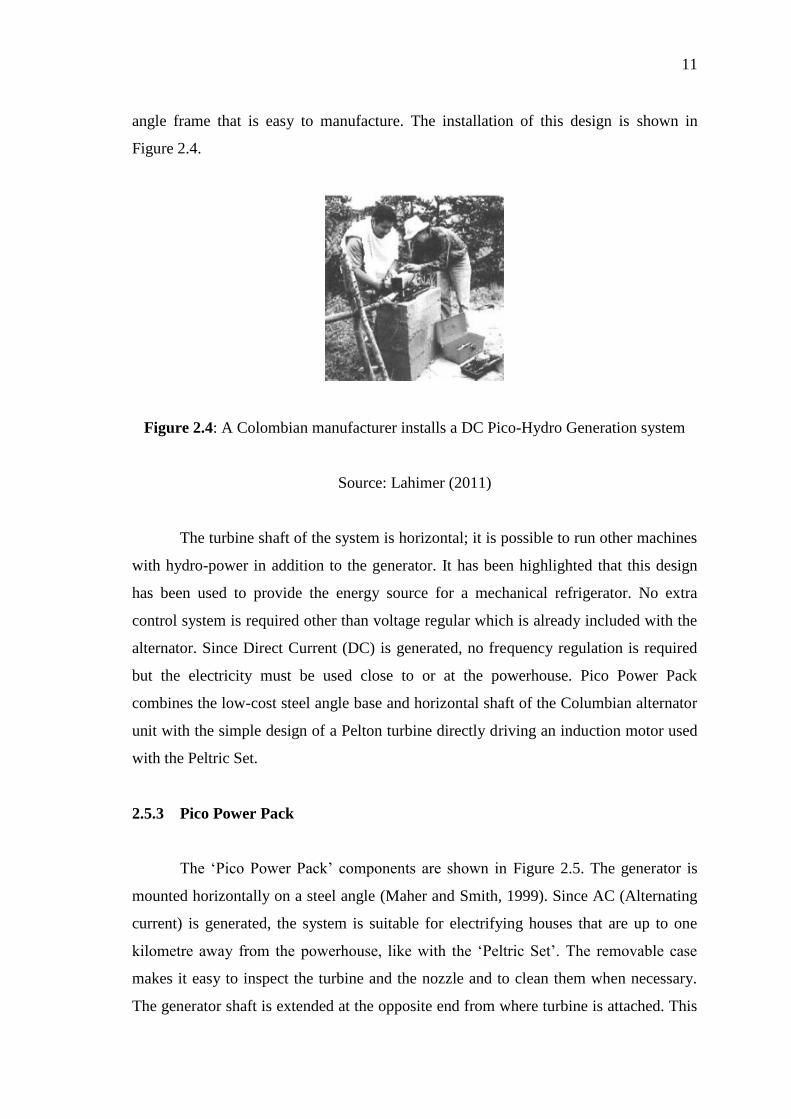
Figure 2.4: A Colombian manufacturer installs a DC Pico-Hydro Generation system
Source: Lahimer (2011)
The turbine shaft of the system is horizontal; it is possible to run other machines
with hydro-power in addition to the generator. It has been highlighted that this design
has been used to provide the energy source for a mechanical refrigerator. No extra
control system is required other than voltage regular which is already included with the
alternator. Since Direct Current (DC) is generated, no frequency regulation is required
but the electricity must be used close to or at the powerhouse. Pico Power Pack
combines the low-cost steel angle base and horizontal shaft of the Columbian alternator
unit with the simple design of a Pelton turbine directly driving an induction motor used
with the Peltric Set.
2.5.3 Pico Power Pack
The ‘Pico Power Pack’ components are shown in Figure 2.5. The generator is
mounted horizontally on a steel angle (Maher and Smith, 1999). Since AC (Alternating
current) is generated, the system is suitable for electrifying houses that are up to one
kilometre away from the powerhouse, like with the ‘Peltric Set’. The removable case
makes it easy to inspect the turbine and the nozzle and to clean them when necessary.
The generator shaft is extended at the opposite end from where turbine is attached. This

12
allows a pulley to be fitted. Small machines such as mills, grinding wheels or saws can
be driven with a pulley. In this way, the hydro-power can be used for a wider range of
productive purposes. The extra money made through running a small business using
Pico-Hydro power, makes it easier to repay the cost of the scheme.
Figure 2.5: The Pico Power Pack generates AC electricity
Source: Maher and Smith (2001)
2.6 PELTON TURBINE
The water strikes the bucket along the tangent of the tangent of the runner. The
energy available at the inlet of the turbine is only Kinetic Energy. The pressure at the
inlet and outlet is atmospheric pressure. The nozzle increases the kinetic energy of the
water flowing through the penstock. At the outlet of the nozzle, the water comes out in
the form of a jet and strikes the buckets (vanes) of the runner. Typically, when using
this type of turbine, water is piped down a hillside so that at the lower end of the pipe, it
emerges from a narrow nozzle as a jet with very high to the turbine blades.
13
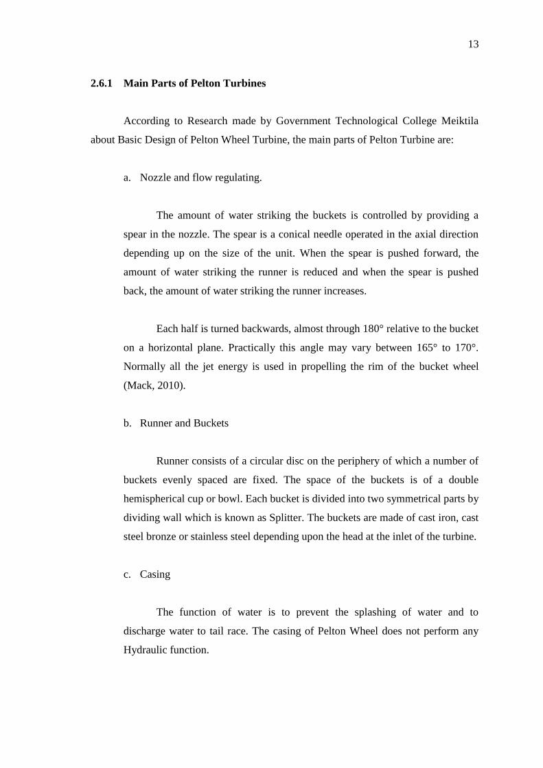
2.6.1 Main Parts of Pelton Turbines
According to Research made by Government Technological College Meiktila
about Basic Design of Pelton Wheel Turbine, the main parts of Pelton Turbine are:
a. Nozzle and flow regulating.
The amount of water striking the buckets is controlled by providing a
spear in the nozzle. The spear is a conical needle operated in the axial direction
depending up on the size of the unit. When the spear is pushed forward, the
amount of water striking the runner is reduced and when the spear is pushed
back, the amount of water striking the runner increases.
Each half is turned backwards, almost through 180° relative to the bucket
on a horizontal plane. Practically this angle may vary between 165° to 170°.
Normally all the jet energy is used in propelling the rim of the bucket wheel
(Mack, 2010).
b. Runner and Buckets
Runner consists of a circular disc on the periphery of which a number of
buckets evenly spaced are fixed. The space of the buckets is of a double
hemispherical cup or bowl. Each bucket is divided into two symmetrical parts by
dividing wall which is known as Splitter. The buckets are made of cast iron, cast
steel bronze or stainless steel depending upon the head at the inlet of the turbine.
c. Casing
The function of water is to prevent the splashing of water and to
discharge water to tail race. The casing of Pelton Wheel does not perform any
Hydraulic function.