experimental analysis of mechanical behavior of lintels in structural ...
9
15 th International Brick and Block Masonry Conference Florianópolis – Brazil – 2012 EXPERIMENTAL ANALYSIS OF MECHANICAL BEHAVIOR OF LINTELS IN STRUCTURAL MASONRY Rezende, Fabiana Martins de 1 ; Rizzatti, Eduardo 2 ; Mohamad, Gihad 2 ; Roman, Humberto Ramos 3 ; Bastos, Marcos Scherer 4 1 Ms. Candidate, Federal University of Santa Maria, Civil Engineering, [email protected] 2 Professor, Federal University of Santa Maria, Civil Engineering Department, [email protected] ; [email protected] 3 PhD, Professor, Federal University of Santa Catarina, Civil Engineering Department, [email protected] 4 Fourth-year undergraduate, Federal University of Santa Maria, Civil Engineering, [email protected] This study deals with experimental analysis of lintels in structural masonry walls built with hollow clay blocks. The main purpose of this study is to observe their mechanical behavior, failure mode and deflections, when subjected to concentrated loading. The experimental program was based on reinforced lintels made with structural blocks and horizontal prefabricated bed joint reinforcements, through the use of MURFOR® steel reinforcement. The test results indicate that the failures occurred by the influence of shear stresses, according to compressions on the top of some blocks that could be observed. Keywords: Structural Masonry, Clay Block, Lintel, MURFOR® reinforcement masonry INTRODUCTION With the heating market in construction, the companies of these sectors are seeking options to carry out works fast and economically. One alternative is the structural masonry, construction system in which the walls make up the structure of the building and also perform the functions of conventional sealing elements. The structural concept of the system is based on transferring loads through compressive stress. The existence of tensile stresses in certain parts is permitted with restrictions to specific points of the structure with low values, due to the low tensile strength of the components of the masonry. However, due to the characteristics related to the project design of the building or attached to some components of the system, tensile stresses with significant values occur at certain location, which require the use of steel reinforcement to inhibit the cracks. As an example, in walls provided with openings, the occurrence of tensile stresses in lintels cannot be avoided. Several authors studied the performance of reinforced masonry. In some studies, as Gouveia (2007), Lourenço (2004) and Pfeffermann (2004), is reported the using of a specific reinforcement in the form of an plane lattice, as MURFOR ®, which is patented and quite common in Europe. However, in Brazil, there has been little research related to this type of reinforcement. Therefore, this paper aims to analyze the mechanical behavior of reinforced lintels with MURFOR ® in the horizontal mortar joint, checking failure mode of the test samples and displacement occurred.
Transcript of experimental analysis of mechanical behavior of lintels in structural ...
15th International Brick and Block Masonry Conference
Florianópolis – Brazil – 2012
EXPERIMENTAL ANALYSIS OF MECHANICAL BEHAVIOR OF LINTELS IN STRUCTURAL MASONRY
Rezende, Fabiana Martins de1; Rizzatti, Eduardo2; Mohamad, Gihad2; Roman, Humberto Ramos3; Bastos, Marcos Scherer4
1 Ms. Candidate, Federal University of Santa Maria, Civil Engineering, [email protected] 2 Professor, Federal University of Santa Maria, Civil Engineering Department, [email protected];
[email protected] 3 PhD, Professor, Federal University of Santa Catarina, Civil Engineering Department, [email protected]
4 Fourth-year undergraduate, Federal University of Santa Maria, Civil Engineering, [email protected]
This study deals with experimental analysis of lintels in structural masonry walls built with hollow clay blocks. The main purpose of this study is to observe their mechanical behavior, failure mode and deflections, when subjected to concentrated loading. The experimental program was based on reinforced lintels made with structural blocks and horizontal prefabricated bed joint reinforcements, through the use of MURFOR® steel reinforcement. The test results indicate that the failures occurred by the influence of shear stresses, according to compressions on the top of some blocks that could be observed.
Keywords: Structural Masonry, Clay Block, Lintel, MURFOR® reinforcement masonry INTRODUCTION With the heating market in construction, the companies of these sectors are seeking options to carry out works fast and economically. One alternative is the structural masonry, construction system in which the walls make up the structure of the building and also perform the functions of conventional sealing elements. The structural concept of the system is based on transferring loads through compressive stress. The existence of tensile stresses in certain parts is permitted with restrictions to specific points of the structure with low values, due to the low tensile strength of the components of the masonry. However, due to the characteristics related to the project design of the building or attached to some components of the system, tensile stresses with significant values occur at certain location, which require the use of steel reinforcement to inhibit the cracks. As an example, in walls provided with openings, the occurrence of tensile stresses in lintels cannot be avoided. Several authors studied the performance of reinforced masonry. In some studies, as Gouveia (2007), Lourenço (2004) and Pfeffermann (2004), is reported the using of a specific reinforcement in the form of an plane lattice, as MURFOR ®, which is patented and quite common in Europe. However, in Brazil, there has been little research related to this type of reinforcement. Therefore, this paper aims to analyze the mechanical behavior of reinforced lintels with MURFOR ® in the horizontal mortar joint, checking failure mode of the test samples and displacement occurred.
15th International Brick and Block Masonry Conference
Florianópolis – Brazil – 2012
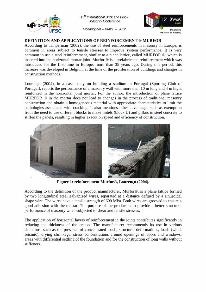
DEFINITION AND APPLICATIONS OF REINFORCEMENT ® MURFOR According to Timperman (2002), the use of steel reinforcements in masonry in Europe, is common in areas subject to tensile stresses to improve system performance. It is very common to use a steel reinforcement, similar to a plane lattice, called MURFOR ®, which is inserted into the horizontal mortar joint. Murfor ® is a prefabricated reinforcement which was introduced for the first time in Europe, more than 35 years ago. During this period, this increase was developed in Belgium at the time of the proliferation of buildings and changes in construction methods. Lourenço (2004), in a case study on building a stadium in Portugal (Sporting Club of Portugal), reports the performance of a masonry wall with more than 10 m long and 4 m high, reinforced in the horizontal joint mortar. For the author, the introduction of plane lattice MURFOR ® in the mortar does not lead to changes in the process of traditional masonry construction and obtain a homogeneous material with appropriate characteristics to limit the pathologies associated with cracking. It also mentions other advantages such as exemption from the need to use different blocks to make lintels (block U) and pillars in steel concrete to stiffen the panels, resulting in higher execution speed and efficiency of construction.
Figure 1: reinforcement Murfor®, Lourenço (2004).
According to the definition of the product manufacturer, Murfor®, is a plane lattice formed by two longitudinal steel galvanized wires, separated at a distance defined by a sinusoidal shape wire. The wires have a tensile strength of 600 MPa. Both wires are grooved to ensure a good adhesion with the mortar. The purpose of the product is to provide a better structural performance of masonry when subjected to shear and tensile stresses. The application of horizontal layers of reinforcement in the joints contributes significantly in reducing the thickness of the cracks. The manufacturer recommends its use in various situations, such as the presence of concentrated loads, structural deformations, loads (wind, seismic), drying shrinkage, stress concentrations around openings of doors and windows, areas with differential settling of the foundation and for the construction of long walls without stiffeners.
15th International Brick and Block Masonry Conference
Florianópolis – Brazil – 2012
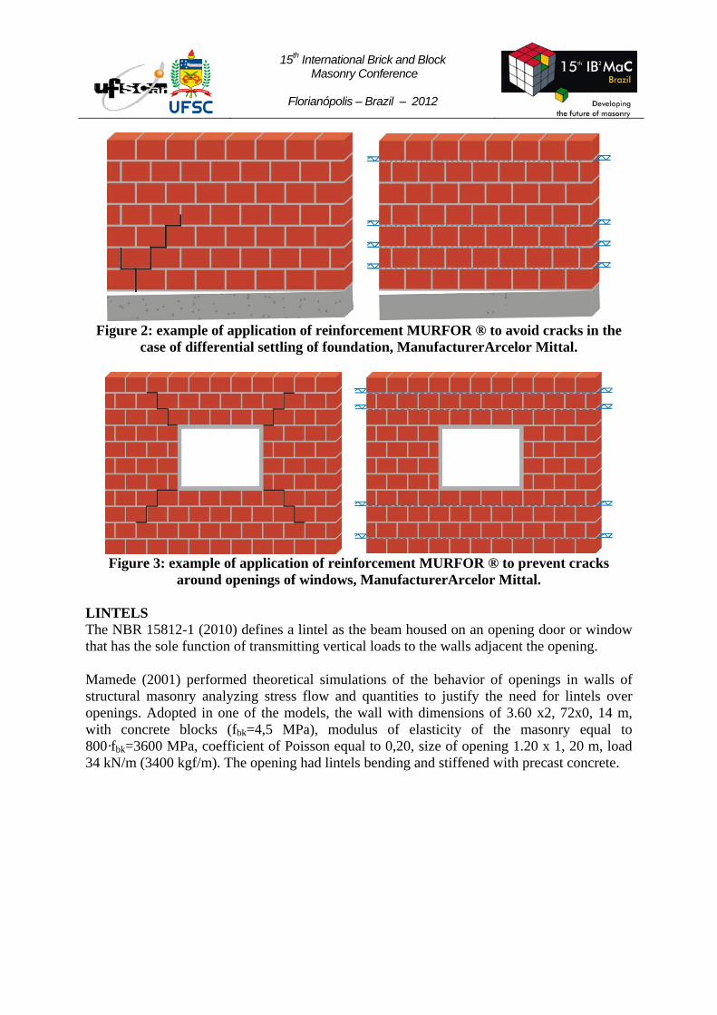
Figure 2: example of application of reinforcement MURFOR ® to avoid cracks in the case of differential settling of foundation, ManufacturerArcelor Mittal.
Figure 3: example of application of reinforcement MURFOR ® to prevent cracks around openings of windows, ManufacturerArcelor Mittal.
LINTELS The NBR 15812-1 (2010) defines a lintel as the beam housed on an opening door or window that has the sole function of transmitting vertical loads to the walls adjacent the opening. Mamede (2001) performed theoretical simulations of the behavior of openings in walls of structural masonry analyzing stress flow and quantities to justify the need for lintels over openings. Adopted in one of the models, the wall with dimensions of 3.60 x2, 72x0, 14 m, with concrete blocks (fbk=4,5 MPa), modulus of elasticity of the masonry equal to 800·fbk=3600 MPa, coefficient of Poisson equal to 0,20, size of opening 1.20 x 1, 20 m, load 34 kN/m (3400 kgf/m). The opening had lintels bending and stiffened with precast concrete.

15th International Brick and Block Masonry Conference
Florianópolis – Brazil – 2012
Figure 4: result of processing finite element modeling: tensions in the horizontal (σx) and vertical (σy), respectively, in kN/cm2, Mamede (2001).
As benchmarks, Mamede (2001) used, based on BS 5628-1 (1992), the following maximum permissible shear stress and compression (on the wall adjacent to the will) in masonry unreinforced: 0,015 kN/cm2 and 2·fmk (0,036 kN/cm2), respectively. Analyzing the simulation results, observed compressive stress greater than the value adopted as the maximum permissible in the upper corners of the openings and concluded that in order to absorb these stresses, the presence of the spar was fundamental and that its length should extend beyond the opening will . EXPERIMENTAL TESTS In order to observe the mechanical behavior of the lintels, five small walls were made, dimensions 2390 x 790 x 140 mm (length, height and width), with structural ceramic blocks and reinforcement Murfor ® in the horizontal mortar joints. The walls were built using hollow ceramic blocks with average size of 289 x 191 x 141 mm (length, height, width), evaluated according to the requirements of NBR 15270-2; cement mortar, lime and sand, 1:0,5:4 recommended by BS 5628-part 1 and a galvanized lattice with steel wire 4 mm in diameter and 115 mm in width. Figure 5 shows the arrangement. Table 1 summarizes the test results of material characterization.
Figure 5: detail of the implementation of the wall.
15th International Brick and Block Masonry Conference
Florianópolis – Brazil – 2012
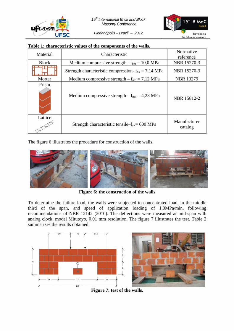
Table 1: characteristic values of the components of the walls.
Material Characteristic Normative reference
Block
Medium compressive strength - fbm = 10,0 MPa NBR 15270-3
Strength characteristic compression- fbk = 7,14 MPa NBR 15270-3
Mortar Medium compressive strength – fam = 7,12 MPa NBR 13279 Prism
Medium compressive strength – fpm = 4,23 MPa NBR 15812-2
Lattice
Strength characteristic tensile–fyk= 600 MPa Manufacturer
catalog
The figure 6 illustrates the procedure for construction of the walls.
Figure 6: the construction of the walls
To determine the failure load, the walls were subjected to concentrated load, in the middle third of the span, and speed of application loading of 1,0MPa/min, following recommendations of NBR 12142 (2010). The deflections were measured at mid-span with analog clock, model Mitutoyo, 0,01 mm resolution. The figure 7 illustrates the test. Table 2 summarizes the results obtained.
Figure 7: test of the walls.

15th International Brick and Block Masonry Conference
Florianópolis – Brazil – 2012
Table 2: Experimental results of ultimate load and flexure moment of walls
Wall Ultimate Load (kN) Maximum flexure moment (kN.m) Wall 1 32,5 10,97 Wall 2 22,0 7,42 Wall 3 20,0 6,75 Wall 4 21,0 7,09 Wall 5 19,0 6,41
Figure 8 shows the result of the displacements measured. Section 1 identifies the beginning of cracking.
Figure 8: value Load x Displacement.
The failure modes of the walls were very similar. On a wall 1, there was failure in the form of a ladder in the corner with visible loss of adhesion between the mortar joint and blocks, beyond the rupture of the outer walls of the blocks near the point of load application. There were no cracks in the mid-span. The figure 9 illustrates the failure mode of wall 1.
Figure 9: detail of failure mode of wall 1. In wall 2, there was failure in the form of a ladder in the corner with visible loss of adhesion between the mortar joint and blocks, in addition to the partial rupture of the blocks near

15th International Brick and Block Masonry Conference
Florianópolis – Brazil – 2012
the point of load application. There were no cracks in the mid-span. The figure 10 illustrates the failure mode of wall 2.
Figure10: failure mode of wall 2. In wall 3, there was failure in the form of a ladder in the corner with visible loss of adhesion between the mortar joint and blocks and a horizontal fissure in the opposite corner. There were no cracks in the mid-span. The figure 11 illustrates the failure mode of wall 3.
Figure11: failure mode of wall 3.
In wall 4, spaced cracks were observed in the corners of the mortar joint. At the point of load application there was cracking in the block. The figure 12 illustrates the failure mode of wall 4.
Figure12: failure mode of wall 4.

15th International Brick and Block Masonry Conference
Florianópolis – Brazil – 2012
In wall 5, there was failure in the form of a ladder at both corners with visible loss of adhesion between the mortar joint and blocks. In one of the points of load application, crushing occurred in the block. There were no cracks in the mid-span. The figure 13 illustrates the failure mode of wall 5.
Figure13: failure mode of wall 5.
CONCLUSION The analysis of failure modes of lintels shows the predominant influence of shear stresses. The absence of cracks in the mid-span of the specimens indicates little effect of flexure stress. The analysis of load versus displacement graph showed a linear elastic behavior until around 80% of ultimate load to failure. REFERENCES Associação Brasileira de Normas Técnicas. NBR 12142: Concreto – Determinação da resistência à tração na flexão de corpos de prova prismáticos. Rio de Janeiro, 2010. 5 p. Associação Brasileira de Normas Técnicas. NBR 13279: Argamassa para assentamento e revestimento de paredes e tetos – Determinação da resistência à tração na flexão e à compressão. Rio de Janeiro, 2005. 9 p. Associação Brasileira de Normas Técnicas. NBR 15270: Componentes cerâmicos – Parte 2. Blocos cerâmicos para alvenaria estrutural – Terminologia e requisitos. Rio de Janeiro. 2005. 11p. Associação Brasileira de Normas Técnicas. NBR 15270: Componentes cerâmicos – Parte 3. Blocos cerâmicos para alvenaria estrutural e de vedação – Métodos de ensaio. Rio de Janeiro. 2005. 27p. Associação Brasileira de Normas Técnicas. NBR 15812: Alvenaria estrutural – Blocos Cerâmicos - Parte 1. Projeto. Rio de Janeiro. 2010. 41p. Associação Brasileira de Normas Técnicas. NBR 15812: Alvenaria estrutural – Blocos Cerâmicos - Parte 2. Execução e controle de obras. Rio de Janeiro. 2010. 41p. British Standards Institution. BSI 5628 – Part 1: code of practice for use of masonry: structural use of unreinforced masonry. London, 1992. 58 p.

15th International Brick and Block Masonry Conference
Florianópolis – Brazil – 2012
Gouveia, J. P.; Lourenço, P.B.; Vasconcelos, G. “Soluções construtivas em alvenaria”. CongressoConstrução - 3.ºCongressoNacional. Coimbra, 2007. Lourenço, P.B. “Design of large size non-loadbearing masonry walls: cases studies in Portugal technical and economical benefits”. 13th InternationalBrickandBlockMasonryConference, Amsterdam, 2004. Mamede, F. C. “Utilização de pré-moldados em edifícios de alvenaria estrutural”. Dissertação (Mestrado em Engenharia de Estruturas). Escola de Engenharia de São Carlos, Universidade de São Paulo. São Carlos. 2001. Pfeffermann, O. “Bed joint reinforced masonry under lateral loading”. 13th International Brick and Block Masonry Conference, Amsterdam, 2004. Timperman, P. “The market for Murfor® reinforced masonry in Europe”. Seminário sobre Paredes de Alvenaria, P.B. Lourenço & H. Sousa (Eds.), Porto, 2002.