Evaluation of puncture resistance force of microneedle by ...
11
Bulletin of the JSME Journal of Biomechanical Science and Engineering Vol.14, No.4, 2019 © 2019 The Japan Society of Mechanical Engineers [DOI: 10.1299/jbse.19-00238] J-STAGE Advance Publication date : 27 September, 2019 Paper No.19-00238 Evaluation of puncture resistance force of microneedle by nonlinear FEM analysis and experimental validation 1. Introduction To meet the demand of reducing physiological and psychological burden on patients, the development of minimally invasive medical devices is desired, of which sizes are minimized compared to present ones. Diabetic patients need to collect a small amount of blood to examine the blood glucose level. For this purpose, they have to bleed blood by puncturing the skin using a lancet needle, i.e., solid needle several times a day. Since the diameter of presently used needle is comparatively thick as from 300 to 650 μm, it gives pain and fear to the patient when puncturing it. On the other hand, humans do not feel pain even when bitten by mosquitoes. The authors have paid attention to the blood sucking mechanism of mosquito and observed the puncturing motion of mosquito's proboscis using a high-speed camera system equipped with a magnified lens having long working distance (Aoyagi et al., 2008; Izumi and Aoyagi, 2007; Aoyagi, 2013; Kitada et al., 2017). As a result, the followings were turned out: the proboscis of mosquito is composed of seven parts (Ikeshoji, 1993; Clement, 2000). One of them, the labrum is a hollow blood sucking needle with a diameter of about 50 μm. On both sides of labrum, there are two maxillae with jagged projections at their tip. The tips of these needles are sharp and small in size, making it easier to avoid pain spots that are distributed at approximately 1 mm intervals on the skin (Iwamura, 2010; Aoyagi, 2016). It was also found that the puncture resistance force is effectively reduced by employing the motion that these three needles are gradually inserted into the skin alternately back and forth with a temporal phase difference to each other (Aoyagi, 2013). Based on these observations, the authors have fabricated Shunki YAMAMOTO*, Tomokazu TAKAHASHI*, Masato SUZUKI*, Seiji AOYAGI*, Toshio NAGASHIMA**, Atsushi KUNUGI***, Makoto CHIYONOBU*** and Takeshi KUROIWA*** *Department of Mechanical Engineering, Kansai University 3-3-35 Yamate-cho, Suita-shi, Osaka 564-8680, Japan E-mail: [email protected] **Department of Engineering and Applied Sciences, Sophia University 7-1 Kioicho, Chiyoda-ku, Tokyo 102-8554, Japan ***JSOL Corporation Tosabori Daibiru Bldg. 2-2-4 Tosabori, Nishi-ku, Osaka 550-0001, Japan Abstract In recent years, a minimally invasive medical needle is required. The development of such a fine needle requires evaluation of puncture resistance force. We have developed various microneedles and conducted the puncture experiments to evaluate their resistance force against an artificial skin made of silicone rubber. In this study, it is attempted to reproduce the puncture experiment by FEM simulation, in which accurate three dimensional (3D) models of needle and skin are constructed, and the conditions of material properties, model size, puncture distance, puncture speed, etc. are set to the same ones as the experiments. As a commercially available nonlinear FEM software, LS-DYNA was employed. The results of FEM analysis and those of experiment were compared to estimate what extent they are matched. As a result, the tendency of the load curve, i.e., transition of resistance force with respect to puncturing distance, and the state of skin deformation were well matched, showing the possibility of FEM analysis to reproduce the experiment. The error of resistance force between analysis and experiment was 20% at most. It is expected that the parameter study would be possible, in which the performance of needle is evaluated by changing the parameters, e.g., its size, shape, how to insert it to the skin, etc. Keywords : Microneedle, Finite element method analysis, Puncture resistance force, Skin deformation, Arbitrary Lagrangian and Eulerian method 1 Received: 16 April 2019; Revised: 5 August 2019; Accepted: 19 September 2019
Transcript of Evaluation of puncture resistance force of microneedle by ...
Bulletin of the JSME
Journal of Biomechanical Science and EngineeringVol.14, No.4, 2019
© 2019 The Japan Society of Mechanical Engineers[DOI: 10.1299/jbse.19-00238]J-STAGE Advance Publication date : 27 September, 2019Paper No.19-00238
Evaluation of puncture resistance force of microneedle by
nonlinear FEM analysis and experimental validation
1. Introduction
To meet the demand of reducing physiological and psychological burden on patients, the development of minimally
invasive medical devices is desired, of which sizes are minimized compared to present ones. Diabetic patients need to
collect a small amount of blood to examine the blood glucose level. For this purpose, they have to bleed blood by
puncturing the skin using a lancet needle, i.e., solid needle several times a day. Since the diameter of presently used
needle is comparatively thick as from 300 to 650 μm, it gives pain and fear to the patient when puncturing it. On the
other hand, humans do not feel pain even when bitten by mosquitoes. The authors have paid attention to the blood sucking
mechanism of mosquito and observed the puncturing motion of mosquito's proboscis using a high-speed camera system
equipped with a magnified lens having long working distance (Aoyagi et al., 2008; Izumi and Aoyagi, 2007; Aoyagi,
2013; Kitada et al., 2017). As a result, the followings were turned out: the proboscis of mosquito is composed of seven
parts (Ikeshoji, 1993; Clement, 2000). One of them, the labrum is a hollow blood sucking needle with a diameter of about
50 μm. On both sides of labrum, there are two maxillae with jagged projections at their tip. The tips of these needles are
sharp and small in size, making it easier to avoid pain spots that are distributed at approximately 1 mm intervals on the
skin (Iwamura, 2010; Aoyagi, 2016). It was also found that the puncture resistance force is effectively reduced by
employing the motion that these three needles are gradually inserted into the skin alternately back and forth with a
temporal phase difference to each other (Aoyagi, 2013). Based on these observations, the authors have fabricated
Shunki YAMAMOTO*, Tomokazu TAKAHASHI*, Masato SUZUKI*, Seiji AOYAGI*, Toshio NAGASHIMA**, Atsushi KUNUGI***, Makoto CHIYONOBU*** and Takeshi KUROIWA***
*Department of Mechanical Engineering, Kansai University
3-3-35 Yamate-cho, Suita-shi, Osaka 564-8680, Japan
E-mail: [email protected]
**Department of Engineering and Applied Sciences, Sophia University
7-1 Kioicho, Chiyoda-ku, Tokyo 102-8554, Japan
***JSOL Corporation
Tosabori Daibiru Bldg. 2-2-4 Tosabori, Nishi-ku, Osaka 550-0001, Japan
Abstract
In recent years, a minimally invasive medical needle is required. The development of such a fine needle requires
evaluation of puncture resistance force. We have developed various microneedles and conducted the puncture
experiments to evaluate their resistance force against an artificial skin made of silicone rubber. In this study, it
is attempted to reproduce the puncture experiment by FEM simulation, in which accurate three dimensional (3D)
models of needle and skin are constructed, and the conditions of material properties, model size, puncture
distance, puncture speed, etc. are set to the same ones as the experiments. As a commercially available nonlinear
FEM software, LS-DYNA was employed. The results of FEM analysis and those of experiment were compared
to estimate what extent they are matched. As a result, the tendency of the load curve, i.e., transition of resistance
force with respect to puncturing distance, and the state of skin deformation were well matched, showing the
possibility of FEM analysis to reproduce the experiment. The error of resistance force between analysis and
experiment was 20% at most. It is expected that the parameter study would be possible, in which the performance
of needle is evaluated by changing the parameters, e.g., its size, shape, how to insert it to the skin, etc.
Keywords : Microneedle, Finite element method analysis, Puncture resistance force, Skin deformation, Arbitrary
Lagrangian and Eulerian method
1
Received: 16 April 2019; Revised: 5 August 2019; Accepted: 19 September 2019
2© 2019 The Japan Society of Mechanical Engineers
Yamamoto, Takahashi, Suzuki, Aoyagi, Nagashima, Kunugi, Chiyonobu and Kuroiwa, Journal of Biomechanical Science and Engineering, Vol.14, No.4 (2019)
[DOI: 10.1299/jbse.19-00238]
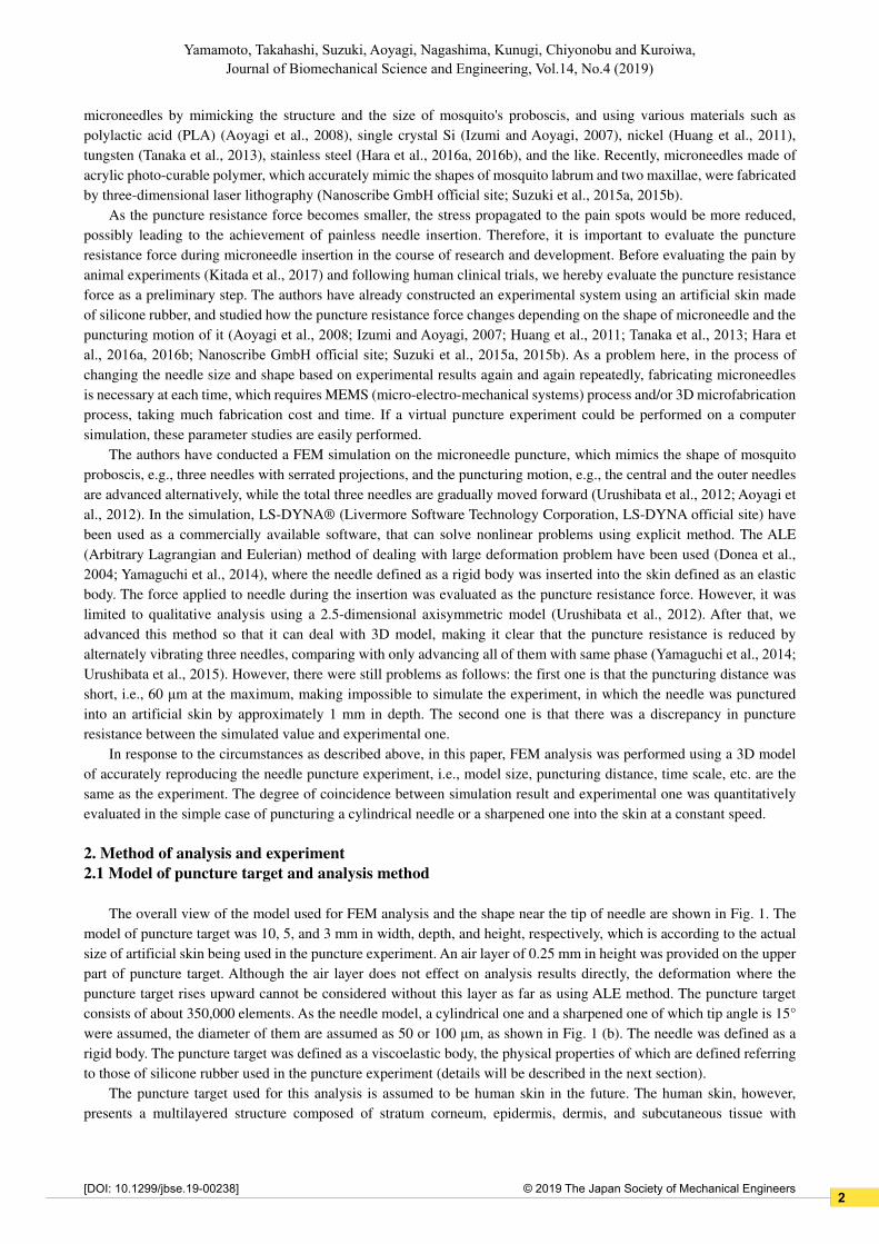
microneedles by mimicking the structure and the size of mosquito's proboscis, and using various materials such as
polylactic acid (PLA) (Aoyagi et al., 2008), single crystal Si (Izumi and Aoyagi, 2007), nickel (Huang et al., 2011),
tungsten (Tanaka et al., 2013), stainless steel (Hara et al., 2016a, 2016b), and the like. Recently, microneedles made of
acrylic photo-curable polymer, which accurately mimic the shapes of mosquito labrum and two maxillae, were fabricated
by three-dimensional laser lithography (Nanoscribe GmbH official site; Suzuki et al., 2015a, 2015b).
As the puncture resistance force becomes smaller, the stress propagated to the pain spots would be more reduced,
possibly leading to the achievement of painless needle insertion. Therefore, it is important to evaluate the puncture
resistance force during microneedle insertion in the course of research and development. Before evaluating the pain by
animal experiments (Kitada et al., 2017) and following human clinical trials, we hereby evaluate the puncture resistance
force as a preliminary step. The authors have already constructed an experimental system using an artificial skin made
of silicone rubber, and studied how the puncture resistance force changes depending on the shape of microneedle and the
puncturing motion of it (Aoyagi et al., 2008; Izumi and Aoyagi, 2007; Huang et al., 2011; Tanaka et al., 2013; Hara et
al., 2016a, 2016b; Nanoscribe GmbH official site; Suzuki et al., 2015a, 2015b). As a problem here, in the process of
changing the needle size and shape based on experimental results again and again repeatedly, fabricating microneedles
is necessary at each time, which requires MEMS (micro-electro-mechanical systems) process and/or 3D microfabrication
process, taking much fabrication cost and time. If a virtual puncture experiment could be performed on a computer
simulation, these parameter studies are easily performed.
The authors have conducted a FEM simulation on the microneedle puncture, which mimics the shape of mosquito
proboscis, e.g., three needles with serrated projections, and the puncturing motion, e.g., the central and the outer needles
are advanced alternatively, while the total three needles are gradually moved forward (Urushibata et al., 2012; Aoyagi et
al., 2012). In the simulation, LS-DYNA® (Livermore Software Technology Corporation, LS-DYNA official site) have
been used as a commercially available software, that can solve nonlinear problems using explicit method. The ALE
(Arbitrary Lagrangian and Eulerian) method of dealing with large deformation problem have been used (Donea et al.,
2004; Yamaguchi et al., 2014), where the needle defined as a rigid body was inserted into the skin defined as an elastic
body. The force applied to needle during the insertion was evaluated as the puncture resistance force. However, it was
limited to qualitative analysis using a 2.5-dimensional axisymmetric model (Urushibata et al., 2012). After that, we
advanced this method so that it can deal with 3D model, making it clear that the puncture resistance is reduced by
alternately vibrating three needles, comparing with only advancing all of them with same phase (Yamaguchi et al., 2014;
Urushibata et al., 2015). However, there were still problems as follows: the first one is that the puncturing distance was
short, i.e., 60 μm at the maximum, making impossible to simulate the experiment, in which the needle was punctured
into an artificial skin by approximately 1 mm in depth. The second one is that there was a discrepancy in puncture
resistance between the simulated value and experimental one.
In response to the circumstances as described above, in this paper, FEM analysis was performed using a 3D model
of accurately reproducing the needle puncture experiment, i.e., model size, puncturing distance, time scale, etc. are the
same as the experiment. The degree of coincidence between simulation result and experimental one was quantitatively
evaluated in the simple case of puncturing a cylindrical needle or a sharpened one into the skin at a constant speed.
2. Method of analysis and experiment
2.1 Model of puncture target and analysis method
The overall view of the model used for FEM analysis and the shape near the tip of needle are shown in Fig. 1. The
model of puncture target was 10, 5, and 3 mm in width, depth, and height, respectively, which is according to the actual
size of artificial skin being used in the puncture experiment. An air layer of 0.25 mm in height was provided on the upper
part of puncture target. Although the air layer does not effect on analysis results directly, the deformation where the
puncture target rises upward cannot be considered without this layer as far as using ALE method. The puncture target
consists of about 350,000 elements. As the needle model, a cylindrical one and a sharpened one of which tip angle is 15°
were assumed, the diameter of them are assumed as 50 or 100 μm, as shown in Fig. 1 (b). The needle was defined as a
rigid body. The puncture target was defined as a viscoelastic body, the physical properties of which are defined referring
to those of silicone rubber used in the puncture experiment (details will be described in the next section).
The puncture target used for this analysis is assumed to be human skin in the future. The human skin, however,
presents a multilayered structure composed of stratum corneum, epidermis, dermis, and subcutaneous tissue with
2

2© 2019 The Japan Society of Mechanical Engineers
Yamamoto, Takahashi, Suzuki, Aoyagi, Nagashima, Kunugi, Chiyonobu and Kuroiwa, Journal of Biomechanical Science and Engineering, Vol.14, No.4 (2019)
[DOI: 10.1299/jbse.19-00238]
different physical properties, making it difficult to create a material model of completely simulating it. For this reason,
as a preliminary step, PDMS (Polydimethylsiloxane, a kind of silicone rubber) was assumed as a puncture target, which
is a material of artificial skin used in the experiments in this paper. PDMS was treated as a viscoelastic model in the FEM
analysis, i.e., MAT_076 (MAT_GENERAL_VISCOELASTIC, viscoelastic body based on the generalized Maxwell
model) (Roylance, MIT web site) was applied in the material card of LS-DYNA. The dynamic viscoelasticity
measurement (Franck, TA Instruments web site) was requested to Mechanical Design Co., Ltd., and the parameters of
MAT_076 were determined based on the measured values.
In this study, the moving needle inserted to the skin is dealt with, of which speed is set to 1 mm/s referring to the
mosquito. The speed affects the resistance force in case that the puncture target is viscoelastic material such as human
skin (Nishio et al., 2016). Considering this, the puncture target is dealt as viscoelastic. If it is dealt as elastic material, the
resistance force due to viscosity cannot be taken account of. In this case, we confirmed that the FEM analysis of needle
puncturing to the skin was liable to be unstable, i.e., the simulation often stopped by the error that the element collapses
to a negative volume, which is may be caused by the lack of repulsive viscous force against the needle speed.
In this study, the puncture resistance force was analyzed when puncturing the needle into puncture target using the
above mentioned FEM model. The puncture distance and puncture speed were set to 1 mm and 1 mm/s, respectively
(same conditions as the experiment described in the next section). Displacement of the bottom surface (xy plane) of
puncture target model was completely constrained. Forced displacement in the height direction (z axis direction) was
given to the needle. The friction coefficient between the needle and the puncture target was set to 1, referring to that the
friction coefficient of rubber against hard materials such as metal, concrete, etc. is reported as approximately from 0.6 to
1.0 (Engineers Edge web site). We confirmed that this coefficient has influence on the resistance force in FEM results
not so much, e.g., the force increased only by 15 % even the coefficient was set to doubled value of 2. Puncture resistance
was calculated by integrating the load in the puncture direction applied to all elements of the skin model (using “nodfor”
which is the output function of LS-DYNA). As mentioned in Chapter 1, LS-DYNA was used for analysis and ALE
method was used as analysis method.
2.2 Puncture experiment and its condition
The experimental setup is shown in Fig. 2. The PDMS artificial skin was punctured by moving the needle in forward
Fig. 1 Analysis model of needle and puncture target
(b) Shape of needle tip
Diameter
50 µm
100 µm
15°
Sharp needle
Cylindrical
needle
0.25 mm
3 mm
Needle
Air layer
Silicone rubber
(PDMS)
(a) Overall view of analysis model
3

2© 2019 The Japan Society of Mechanical Engineers
Yamamoto, Takahashi, Suzuki, Aoyagi, Nagashima, Kunugi, Chiyonobu and Kuroiwa, Journal of Biomechanical Science and Engineering, Vol.14, No.4 (2019)
[DOI: 10.1299/jbse.19-00238]
and back directions using a linear slider. The mixing ratio of PDMS pre-polymer and curing agent is 30:1, and it was
cured by heating at 90 ℃ for 24 hours. The dimensions of the test piece are equivalent to the analysis model (10 mm ×
5 mm × 3 mm). The force applied to skin, i.e., puncture resistance force, was measured using a load cell (TGRV02-2NB,
Tec Gihan Co., Ltd., rated load: 204 gf, resolution: 0.01 gf), which can sufficiently detect the minute load in the following
puncture experiment. The shape and diameter of needle, puncture distance, and puncture speed are the same as the
conditions in FEM analysis described in the previous section. Tungsten was used as the material of needle, considering
its sufficient hardness to regard it as rigid body in FEM simulation. The density, Young's modulus, and Poisson's ratio of
tungsten are 19,300 kg/m3, 411 GPa, and 0.28, respectively. The tip of the tungsten wire was cut (sharpened) by laser
processing using a femtosecond laser beam (Hara et al., 2016a, 2016b). Adding to say, tungsten is biologically inert to
the living body; for example, it is used as a sharpen tool for dissecting the body, etc. (Brady, 1965; Tanaka et al., 2013).
3. Results of FEM analysis and experiment
3.1 Comparison between analysis and experiment in tensile test (confirmation of material properties)
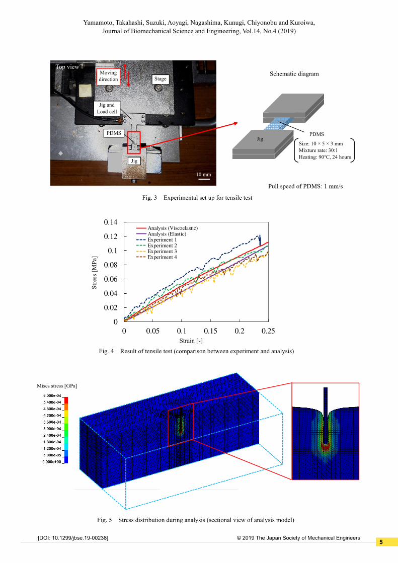
A tensile test using PDMS was experimentally conducted to obtain the relationship between stress and strain, which
was calculated from the measured load and displacement. The experimental set up for tensile test is shown in Fig. 3. The
test was conducted four times. In LS-DYNA, on the other hand, analysis of this tensile test was carried out using material
parameters based on the viscoelasticity measurement results described above. The fracture or yield stress was not
considered. At this time, the fracture phenomenon is approximately expressed by large deformation of ALE analysis.
Taking the fracture into account in ALE analysis is future work. For reference, the analysis was also conducted by
defining the material as elastic one.
The results are shown in Fig. 4. By comparing the FEM analyzed result and the experimental one in this figure, it is
confirmed that the material parameters used in LS-DYNA were able to reproduce actual material properties within the
error of approximately 10% both in regarding the material as viscoelastic and elastic. Young's modulus obtained from
this result is approximately 0.4 MPa. In this tensile test, the FEM processing works well even in case of elastic material;
however, in needle puncture analysis, it is liable to be unstable as abovementioned. Therefore, the material is dealt with
as viscoelastic one in the following of this article.
3.2 Comparison between analysis and experiment when puncturing cylindrical needle with a diameter
of 100 μm
FEM analysis results and experimental ones were compared in case that a cylindrical needle with diameter of 100
μm was punctured. Figure 5 shows the FEM analyzed von Mises' stress distribution on cross section of puncture target
when punctured by 1,000 μm in depth.
Micro- scope
Needle
Linear slider
Stage
Stand
Load cell
Artificial skin (PDMS)
(Puncture direction)
Fig. 2 Conceptual diagram of puncture experiment equipment
4
2© 2019 The Japan Society of Mechanical Engineers
Yamamoto, Takahashi, Suzuki, Aoyagi, Nagashima, Kunugi, Chiyonobu and Kuroiwa, Journal of Biomechanical Science and Engineering, Vol.14, No.4 (2019)
[DOI: 10.1299/jbse.19-00238]
0
0.02
0.04
0.06
0.08
0.1
0.12
0.14
0 0.05 0.1 0.15 0.2 0.25
Analysis (Viscoelastic)Analysis (Elastic)Experiment 1Experiment 2Experiment 3Experiment 4
Strain [-]
Fig. 4 Result of tensile test (comparison between experiment and analysis)
Str
ess
[MP
a]
Fig. 3 Experimental set up for tensile test
PDMS
Jig and
Load cell
Jig
Stage
Moving
direction
Top view
10 mm
Jig PDMS
Schematic diagram
Size: 10 × 5 × 3 mm
Mixture rate: 30:1
Heating: 90℃, 24 hours
Pull speed of PDMS: 1 mm/s
Fig. 5 Stress distribution during analysis (sectional view of analysis model)
Mises stress [GPa]
5
2© 2019 The Japan Society of Mechanical Engineers
Yamamoto, Takahashi, Suzuki, Aoyagi, Nagashima, Kunugi, Chiyonobu and Kuroiwa, Journal of Biomechanical Science and Engineering, Vol.14, No.4 (2019)
[DOI: 10.1299/jbse.19-00238]
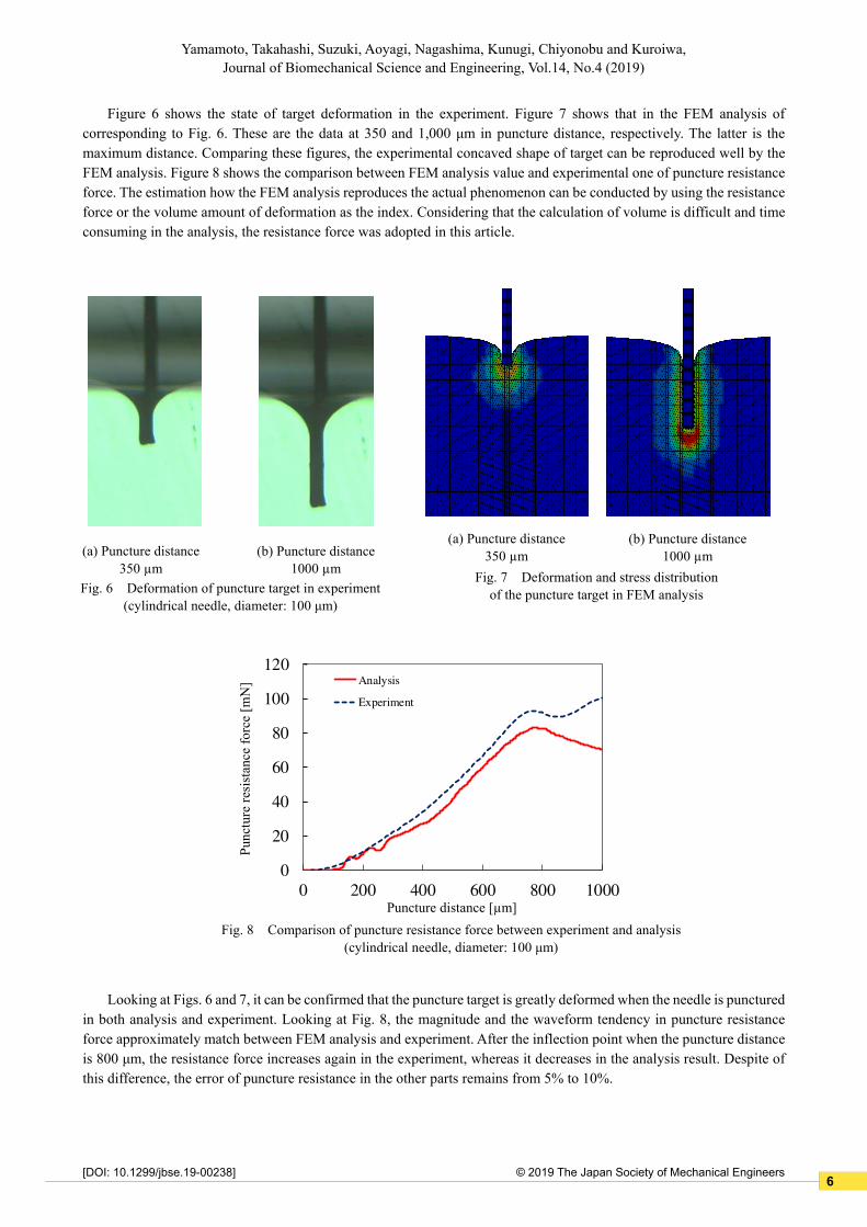
Figure 6 shows the state of target deformation in the experiment. Figure 7 shows that in the FEM analysis of
corresponding to Fig. 6. These are the data at 350 and 1,000 μm in puncture distance, respectively. The latter is the
maximum distance. Comparing these figures, the experimental concaved shape of target can be reproduced well by the
FEM analysis. Figure 8 shows the comparison between FEM analysis value and experimental one of puncture resistance
force. The estimation how the FEM analysis reproduces the actual phenomenon can be conducted by using the resistance
force or the volume amount of deformation as the index. Considering that the calculation of volume is difficult and time
consuming in the analysis, the resistance force was adopted in this article.
Looking at Figs. 6 and 7, it can be confirmed that the puncture target is greatly deformed when the needle is punctured
in both analysis and experiment. Looking at Fig. 8, the magnitude and the waveform tendency in puncture resistance
force approximately match between FEM analysis and experiment. After the inflection point when the puncture distance
is 800 μm, the resistance force increases again in the experiment, whereas it decreases in the analysis result. Despite of
this difference, the error of puncture resistance in the other parts remains from 5% to 10%.
(a) Puncture distance
350 µm
Fig. 6 Deformation of puncture target in experiment
(cylindrical needle, diameter: 100 μm)
(b) Puncture distance
1000 µm
(a) Puncture distance
350 µm
Fig. 7 Deformation and stress distribution
of the puncture target in FEM analysis
(b) Puncture distance
1000 µm
0
20
40
60
80
100
120
0 200 400 600 800 1000
Analysis
Experiment
Puncture distance [µm]
Fig. 8 Comparison of puncture resistance force between experiment and analysis
(cylindrical needle, diameter: 100 μm)
Pun
cture
res
ista
nce
forc
e [m
N]
6
2© 2019 The Japan Society of Mechanical Engineers
Yamamoto, Takahashi, Suzuki, Aoyagi, Nagashima, Kunugi, Chiyonobu and Kuroiwa, Journal of Biomechanical Science and Engineering, Vol.14, No.4 (2019)
[DOI: 10.1299/jbse.19-00238]
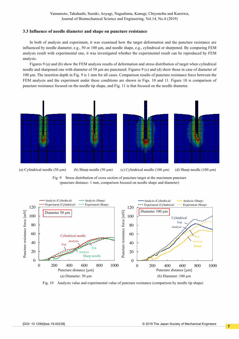
3.3 Influence of needle diameter and shape on puncture resistance
In both of analysis and experiment, it was examined how the target deformation and the puncture resistance are
influenced by needle diameter, e.g., 50 or 100 μm, and needle shape, e.g., cylindrical or sharpened. By comparing FEM
analysis result with experimental one, it was investigated whether the experimental result can be reproduced by FEM
analysis.
Figures 9 (a) and (b) show the FEM analysis results of deformation and stress distribution of target when cylindrical
needle and sharpened one with diameter of 50 μm are punctured. Figures 9 (c) and (d) show those in case of diameter of
100 μm. The insertion depth in Fig. 9 is 1 mm for all cases. Comparison results of puncture resistance force between the
FEM analysis and the experiment under these conditions are shown in Figs. 10 and 11. Figure 10 is comparison of
puncture resistance focused on the needle tip shape, and Fig. 11 is that focused on the needle diameter.
(a) Cylindrical needle (50 µm)
Fig. 9 Stress distribution of cross section of puncture target at the maximum puncture
(puncture distance: 1 mm, comparison focused on needle shape and diameter)
(b) Sharp needle (50 µm) (c) Cylindrical needle (100 µm) (d) Sharp needle (100 µm)
0
20
40
60
80
100
120
0 200 400 600 800 1000
Analysis (Cylindrical) Analysis (Sharp)
Experiment (Cylindrical) Experiment (Sharp)
0
20
40
60
80
100
120
0 200 400 600 800 1000
Analysis (Cylindrical) Analysis (Sharp)
Experiment (Cylindrical) Experiment (Sharp)
Fig. 10 Analysis value and experimental value of puncture resistance (comparison by needle tip shape)
Puncture distance [µm]
(a) Diameter: 50 µm
Pu
nct
ure
res
ista
nce
forc
e [m
N]
Diameter 50 µm
Cylindrical needle
Sharp needle
Analysis
Exp.
Analysis
Exp.
Puncture distance [µm]
(b) Diameter: 100 µm
Pu
nct
ure
res
ista
nce
forc
e [m
N] Diameter 100 µm
Cylindrical
Sharp
Exp.
Analysis
Exp.
Analysis
7
2© 2019 The Japan Society of Mechanical Engineers
Yamamoto, Takahashi, Suzuki, Aoyagi, Nagashima, Kunugi, Chiyonobu and Kuroiwa, Journal of Biomechanical Science and Engineering, Vol.14, No.4 (2019)
[DOI: 10.1299/jbse.19-00238]
3.3.1 Effect of needle shape
As shown in Fig. 10 (a), when a needle with diameter of 50 μm is punctured, the puncture resistances in analysis and
experiment are almost the same, and the error between them is about 5% at the maximum. In both of analysis and
experiment, the puncture resistance in case of using the sharpened needle is slightly smaller, e.g., 2 or 3%, than that of
using the cylindrical needle.
As shown in Fig. 10 (b), in the case of diameter of 100 μm, the resistance force in case of sharp needle is smaller
than that of cylindrical one, as same as the case of 50 μm. The degree of reduction is approximately 10%, which is larger
than the case of diameter of 50 μm. The effect of reducing the puncture resistance due to the tip shape is larger in thick
needle compared to that in thin one.
As shown in Fig. 10 (b), when a cylindrical needle with diameter of 100 μm is punctured, the puncture resistances
in analysis and the experiment are matched well until the inflection point of curve at about 800 μm. However, after this
point, the trend of analysis and experimental curves differ from each other. At the inflection point, the needle breaks
through the puncture target, e.g., the state of target changes from concavely deformed to really penetrated. This situation
is shown in Fig. 12. The deformation of target increases until the inflection point, and after that, it is alleviated because
the target is perforated by the needle.
0
20
40
60
80
100
120
0 200 400 600 800 1000
Analysis (50 μm) Analysis (100 μm)
Experiment (50 μm) Experiment (100 μm)
0
20
40
60
80
100
120
0 200 400 600 800 1000
Analysis (50 μm) Analysis (100 μm)
Experiment (50 μm) Experiment (100 μm)
Fig. 11 Analysis value and experimental one of puncture resistance (comparison by needle diameter)
Puncture distance [µm]
(a) Cylindrical needle
Pun
cture
res
ista
nce
forc
e [m
N]
Cylindrical needle
50 µm
100 µm
Exp.
Analysis
Exp.
Analysis
Puncture distance [µm]
(b) Sharp needle
Pun
cture
res
ista
nce
forc
e [m
N]
Sharp needle
100 µm
50 µm
Exp.
Analysis
Exp.
Analysis
Fig. 12 Deformation of puncture target near the inflection point (cylindrical needle, diameter: 100 μm).
Concaved deformation increases before inflection point, i.e., a < b. After that it is alleviated, i.e., b > c.
(a) Experiment (b) Analysis
500 µm 700 µm 900 µm 500 µm 700 µm 900 µm
Puncture distance Puncture distance
a
b c
Deformation
increases.
Deformation
decreases.
Concaved
deformation
Deformation
increases.
Deformation
decreases.
a b c
8
2© 2019 The Japan Society of Mechanical Engineers
Yamamoto, Takahashi, Suzuki, Aoyagi, Nagashima, Kunugi, Chiyonobu and Kuroiwa, Journal of Biomechanical Science and Engineering, Vol.14, No.4 (2019)
[DOI: 10.1299/jbse.19-00238]
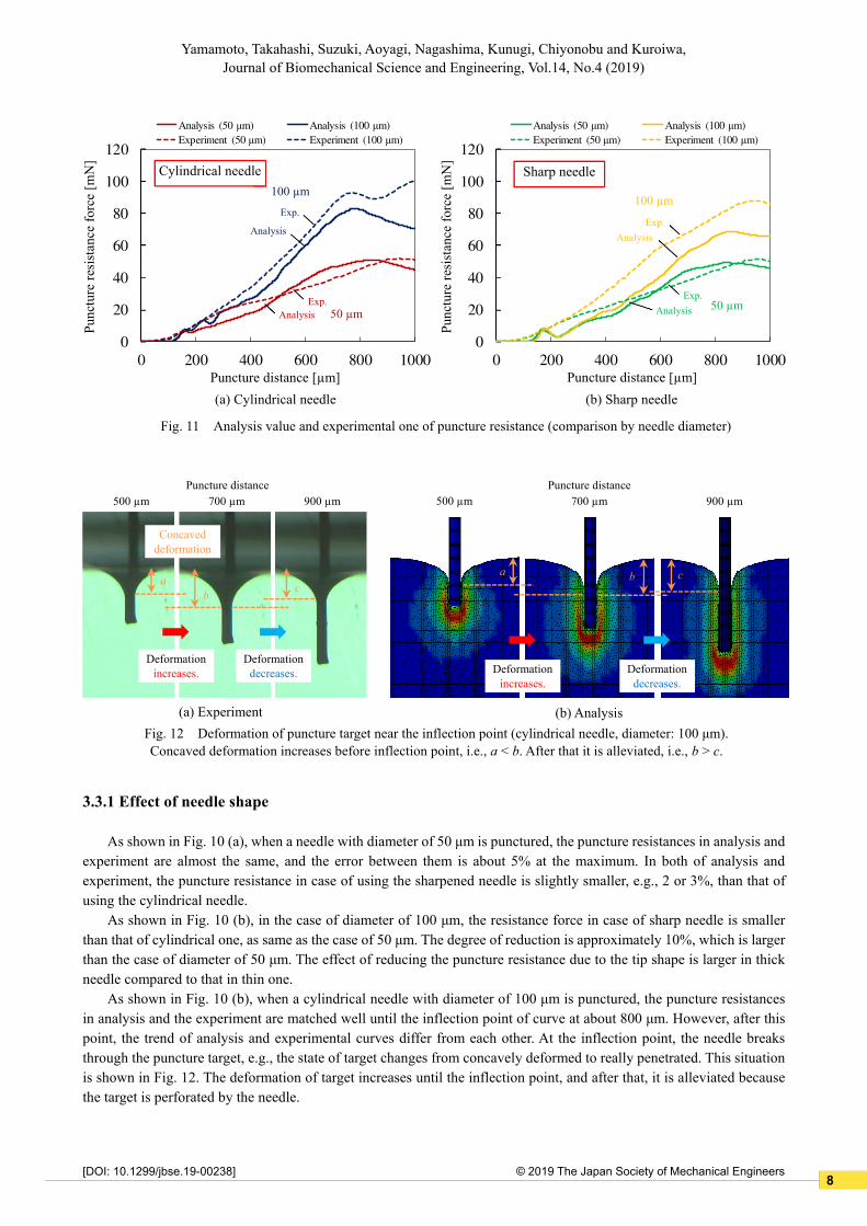
3.3.2 Effect of needle diameter
As shown in Figs. 11 (a) and (b), the resistance force in case with diameter of 50 μm is smaller than that of 100 μm,
regardless of cylindrical or sharp shape. As shown in Fig. 11 (a), in case of the cylindrical needle, the resistance force is
much reduced when the diameter decreases both in FEM analysis and experiment. On the other hand, as shown in Fig.
11 (b), it is not reduced so much, especially in FEM analysis, which is affected by that FEM analyzed value is smaller
than experimental one in case of diameter of 100 μm. The reason why the resistance force is underestimated in FEM
analysis compared to the experiment is not clear at the present.
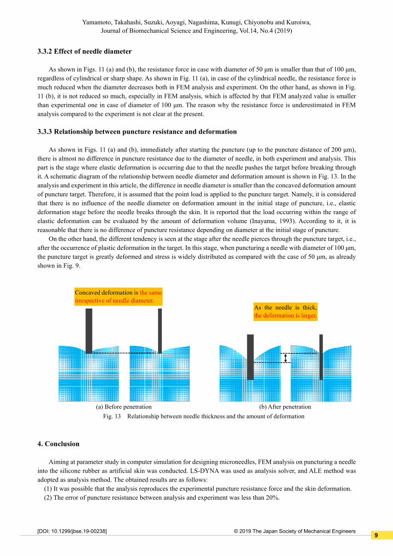
3.3.3 Relationship between puncture resistance and deformation
As shown in Figs. 11 (a) and (b), immediately after starting the puncture (up to the puncture distance of 200 μm),
there is almost no difference in puncture resistance due to the diameter of needle, in both experiment and analysis. This
part is the stage where elastic deformation is occurring due to that the needle pushes the target before breaking through
it. A schematic diagram of the relationship between needle diameter and deformation amount is shown in Fig. 13. In the
analysis and experiment in this article, the difference in needle diameter is smaller than the concaved deformation amount
of puncture target. Therefore, it is assumed that the point load is applied to the puncture target. Namely, it is considered
that there is no influence of the needle diameter on deformation amount in the initial stage of puncture, i.e., elastic
deformation stage before the needle breaks through the skin. It is reported that the load occurring within the range of
elastic deformation can be evaluated by the amount of deformation volume (Inayama, 1993). According to it, it is
reasonable that there is no difference of puncture resistance depending on diameter at the initial stage of puncture.
On the other hand, the different tendency is seen at the stage after the needle pierces through the puncture target, i.e.,
after the occurrence of plastic deformation in the target. In this stage, when puncturing a needle with diameter of 100 μm,
the puncture target is greatly deformed and stress is widely distributed as compared with the case of 50 μm, as already
shown in Fig. 9.
4. Conclusion
Aiming at parameter study in computer simulation for designing microneedles, FEM analysis on puncturing a needle
into the silicone rubber as artificial skin was conducted. LS-DYNA was used as analysis solver, and ALE method was
adopted as analysis method. The obtained results are as follows:
(1) It was possible that the analysis reproduces the experimental puncture resistance force and the skin deformation.
(2) The error of puncture resistance between analysis and experiment was less than 20%.
(a) Before penetration
Concaved deformation is the same
irrespective of needle diameter. As the needle is thick,
the deformation is larger.
Fig. 13 Relationship between needle thickness and the amount of deformation
(b) After penetration
9

2© 2019 The Japan Society of Mechanical Engineers
Yamamoto, Takahashi, Suzuki, Aoyagi, Nagashima, Kunugi, Chiyonobu and Kuroiwa, Journal of Biomechanical Science and Engineering, Vol.14, No.4 (2019)
[DOI: 10.1299/jbse.19-00238]
(3) Analysis and experiment were carried out by changing the diameter and the shape of needle. As a result, the
resistance force when puncturing a needle with diameter of 50 μm was smaller compared to that of 100 μm. The
resistance force when puncturing a sharp needle was smaller compared to that puncturing a cylindrical one.
Acknowledgement
This work was supported by KAKENHI (18H01415) from JSPS (Japanese Society for the Promotion of Science).
This work was supported in part by a Strategic Research Foundation at Private Universities "Creation of 3D nano-micro
structures and its application to biomimetics and medicine" from MEXT (Ministry of Education, Culture, Sport, Science,
and Technology, Japan), 2015-2019.
References
Aoyagi, S., Overview of Microneedles, Journal of the Japan Society for Precision Engineering, Vol. 82, No. 12 (2016),
pp. 999-1004 (in Japanese).
Aoyagi, S., Visualization in Development of Microneedle - Development of Painless Needle Imitating Mosquito -,
Journal of the Visualization Society of Japan, Vol. 33, No. 131 (2013), pp. 145-148 (in Japanese).
Aoyagi, S., Izumi, H. and Fukuda, M., Biodegradable Polymer Needle with Various Tip Angles and Consideration on
Insertion Mechanism of Mosquito's Proboscis, Sensors & Actuators, Vol. A143/1 (2008), pp. 20-28.
Aoyagi, S., Takaoki, Y., Takayanagi, H., Huang, C-H., Tanaka, T., Suzuki, M., Takahashi, T., Kanzaki, T. and Matsumoto,
T., Equivalent Negative Stiffness Mechanism Using Three Bundled Needles Inspired by Mosquito for Achieving
Easy Insertion, 2012 IEEE/RSJ International Conference on Intelligent Robots and Systems (IROS 2012), pp. 2295-
2300.
Brady, J., A simple technique for making very fine, durable dissecting needles by sharpening tungsten wire
electrolytically, Bulletin of the World Health Organization, Vol. 32, No. 1 (1965), pp. 143-144.
Clement, A. N., The Biology of Mosquitoes, CABI Publishing (2000), pp. 224-234.
Donea, J., Huerta, A., Ponthot, J.-Ph. and Rodriguez-Ferran, A., Arbitrary Lagrangian–Eulerian Methods, Encyclopedia
of Computational Mechanics, Volume 1: Fundamentals, Chapter 14 (2004).
Engineers Edge web site (online),
available from <https://www.engineersedge.com/coeffients_of_friction.htm>, (accessed on 10 July, 2019).
Franck, A., Viscoelasticity and dynamic mechanical testing, TA Instruments web site (online),
available from <http://tainstruments.com/pdf/literature/AAN004_Viscoelasticity_and_DMA.pdf>,
(accessed on 6 March, 2019).
Hara, Y., Yamada, M., Tatsukawa, C., Takahashi, T., Suzuki, M. and Aoyagi, S., Fabrication of Stainless Steel
Microneedle with Laser-Cut Sharp Tip and its Penetration and Blood Sampling Performance, International Journal
of Automation Technology, Vol. 10, No. 6 (2016), pp. 950-957.
Hara, Y., Yamada, M., Tatsukawa, C., Takahashi, T., Suzuki, M. and Aoyagi, S., Laser Fabrication of Jagged-Shaped
Stainless Steel Microneedle Imitating Mosquito’s Maxilla, International Journal of Automation Technology, Vol. 10,
No. 6 (2016), pp. 958-964.
Huang, C-H., Tanaka, T., Takaoki, Y., Izumi, H., Takahashi, T., Suzuki, M. and Aoyagi, S., Fabrication of Metallic
Microneedle by Electroplating and Sharpening of it by Electrochemical Etching, The transactions of the Institute of
Electrical Engineers of Japan, Sec. E (Sensors and Micromachines), Vol. 131, No. 11 (2011), pp. 373-380 (in
Japanese).
Ikeshoji, T., Mosquito, University of Tokyo Press (1993) (in Japanese).
Inayama, M., Study on compression perpendicular to the grain in wood Part 4: Analytic functions for the relation between
compression load and elastic deformation perpendicular to the grain in wood, Summaries of technical papers of
annual meeting of Architectural Institute of Japan (1993), pp. 907-908 (in Japanese).
Iwamura, Y., Touch and Somatosensation, The Institute of Electronics, Information and Communication Engineers
"Knowledge base", S3 group - volume 2 - chapter 3 (2010), pp. 1-10 (in Japanese).
Izumi, H. and Aoyagi, S., Novel Fabrication Method for Long Silicon Microneedles with Three-Dimensional Sharp Tips
10

2© 2019 The Japan Society of Mechanical Engineers
Yamamoto, Takahashi, Suzuki, Aoyagi, Nagashima, Kunugi, Chiyonobu and Kuroiwa, Journal of Biomechanical Science and Engineering, Vol.14, No.4 (2019)
[DOI: 10.1299/jbse.19-00238]
and Complicated Shank Shapes by Isotropic Dry Etching, Transaction on Electrical and Electronic Engineering, Vol.
2, No. 3 (2007), pp. 328-334.
Kitada, H., Yamamoto, H., Yamamoto, S., Suzuki, M., Aoyagi, S., Takahashi, T., Fukunaga, K., Hosomi, R., Takazawa,
T., Uta, D., Kawajiri, Y., Nakayama, K. and Hikitsuchi, T., Observation of Mosquito Skin Penetration and Blood
Suction in laboratory animals, Proceedings of 2017 JSPE Autumn Meeting, N-18, pp. 897-898 (in Japanese).
Livermore Software Technology Corporation (LSTC), LS-DYNA official site (online),
available from <http://www.lstc.com/products/ls-dyna>, (accessed on 6 March, 2019).
Nanoscribe GmbH official site (online), available from <https://www.nanoscribe.de/>, (accessed on 6 March, 2019).
Nishio, Y., Ito, Y., Kishida, R., Kagiyama, Y. and Nemoto, T., Dynamic Viscoelasticity Properties Evaluation of Skin and
Making of Dummy Skin for Safety Evaluation, Journal of the Japanese Society for Experimental Mechanics, Vol. 16,
No. 4 (2016), pp. 307-314 (in Japanese).
Roylance, D., Engineering viscoelasticity, MIT web site (online),
available from <http://web.mit.edu/course/3/3.11/www/modules/visco.pdf>, (accessed on 6 March, 2019).
Suzuki, M., Sawa, T., Takahashi, T. and Aoyagi, S., Fabrication of Microneedle Mimicking Mosquito Proboscis Using
Nanoscale 3D Laser Lithography System, International Journal of Automation Technology, Vol. 9 No. 6 (2015), pp.
655-661.
Suzuki, M., Sawa, T., Terada, Y., Takahashi, T. and Aoyagi, S., Fabrication of Microneedles Precisely Imitating
Mosquito’s Proboscis by Nanoscale Tree Dimensional Laser Lithography and Its Characterization, The 18th
International Conference on Solid-State Sensors, Actuators and Microsystems (Transducers 2015), M4D.007, pp.
121-124.
Tanaka, T., Takahashi, T., Suzuki, M. and Aoyagi, S., Development of Minimally Invasive Microneedle Made of Tungsten
– Sharpening Through Electrochemical Etching and Hole Processing for Drawing up Liquid Using Excimer Laser -,
Journal of Robotics and Mechatronics, Vol. 25, No. 4 (2013), pp. 755-761.
Urushibata, Y., Takaoki, Y., Tanaka, T., Takahashi, T., Suzuki, M., Aoyagi, S., Kanzaki, T., Yamaguchi, S. and Imazato,
S., Explicit Finite Element Analysis of Mosquito's Needle Insertion Mechanism, Proceedings of JSME Conference
on Robotics and Mechatronics (Robomec 2012), 1A1-R07 (in Japanese).
Urushibata, Y., Yamamoto, S., Suzuki, M., Takahashi, T., Aoyagi, S., Yamaguchi, S., Imazato, S., Kunugi, A. and
Saruwatari, T., Study of vibration effect in puncture of mosquito's labrum - Non-linear FEM analysis and visualization
of stress applied to skin -, Proceedings of JSME Conference on Robotics and Mechatronics (Robomec 2015), 1P1-
R07 (in Japanese).
Yamaguchi, S., Tsutsui, K., Satake, K., Morikawa, S., Shirai, Y. and Tanaka, H.T., Dynamic analysis of a needle insertion
for soft materials: Arbitrary Lagrangian–Eulerian-based three-dimensional finite element analysis, Computers in
Biology and Medicine 53 (2014), pp. 42-47.
11