
Evaluation of Existing Arch Dam Design Criteria in Lieu … · ANCOLD Guidelines on Design Criteria...
15
Evaluation of Existing Arch Dam Design Criteria in Lieu of ANCOLD Guidelines Marius Jonker and Dr Radin Espandar GHD Pty Ltd This paper provides a summary of the current state of practice for arch dam design criteria that have been adopted by some international dam organizations, and where relevant, compares that with the criteria provided in the updated ANCOLD Guidelines on Design Criteria for Concrete Gravity Dams, with the view to provide a basis for consistent and unified design criteria for arch dams in Australia. The paper draws on the authors’ experience with arch dams, including recent experience with a number of arch dam safety reviews in Australia, their past experience with arch dams over 200 m height, as well as their involvement with the development of the mentioned updated ANCOLD Guidelines. Since the last arch dam was constructed in Australia, a number of international publications have been released on arch dam design practices, providing general information and guidance for the design of new dams and evaluation of the safety and structural integrity of existing arch dams. This paper compares these publications and proposes criteria that are aligned with the ANCOLD gravity dam guidelines. Keywords: Arch dams; Design Criteria Introduction The ANCOLD register includes 43 arch dams constructed between 1857 and 1974, ranging from about 15 m to 140 m in height. Although there have been no new arch dams constructed in Australia for many years, the safety of existing arch dams are required to comply with various state dam safety regulatory requirements, which often refer to, or are aligned with, the ANCOLD guidelines. ANCOLD has developed guidelines to enhance the ability of dam organizations to assure that adequate safety programs and practices are in place. However, only three guidelines cover particular types of dams, whilst the others deal generally with flood capacity and earthquake design, and dam safety and environmental management practices. Except for limited information regarding earthquake design in ANCOLD (1998), and selected information in ANCOLD (2013), none of them deals specifically with arch dams design criteria. In the absence of a single recognized guideline covering the various design aspects of arch dams, there is currently inconsistency in the underlying principles in the review processes of arch dams in Australia. Since the last arch dam was constructed in Australia, a number of international publications have been released on arch dam design practices, e.g. by the US Bureau of Reclamation (1977, 2006), USACE (1994) and FERC (1999). These publications provide general information and guidance on the design of new arch dams, and for the evaluation of the safety and structural integrity of existing arch dams, including design criteria, material properties, loads and load combinations and evaluation procedures. This paper provides a summary of the current state of practice for arch dam design criteria that have been adopted by these international dam organizations, and compares that with the criteria provided in the updated ANCOLD Guidelines on Design Criteria for Concrete Gravity Dams (2013), with the view to provide a basis for consistent and unified design criteria for arch dams in Australia. Key concepts of arch dams Concrete arch dams are complex three-dimensional shell structures that are thinner but have more redundancies than gravity dams. They carry load both in a vertical plane by cantilever action into the base foundation, as well as horizontally by arch action into the abutments. Arch dams thus resist the water pressure and other loads by self-weight and by transmitting the load by arch action into the valley walls or into concrete gravity thrust blocks. Typically the arch action reduces the bending (cantilever) stresses and adds load carrying capacity. The abutments and foundations must therefore be of sufficient strength to support the arch thrust. Arch dam structures are curved towards upstream with either single curvature (curved only in plan) or double curvature (curve both in plan and section). An arch- gravity dam or curved-gravity dam has the characteristics of both an arch dam and a gravity dam, but can be thinner than the pure gravity dam. An arch structure has to be monolithic to achieve successful arch action, i.e. no structural discontinuities, such as open joints or cracks, should exist at the time the water load is applied. The shape and curvature of an arch dam, its contact with the foundation and the stability of the foundations are the most important design features in providing stability and favourable stress conditions. The desired stresses and stability is achieved most economically by proper shaping and the use of both horizontal and vertical curvature, rather than by adding to the thickness of the dam. The ideal arch shape depends on the valley shape, with typically a high degree of horizontal curvature in relatively narrow valleys, and poly-centred, parabolic or elliptically shaped arches in wider sites. Arch dams provide redundant load carrying capacity, i.e. if one part of the structure is overstressed, the load can be transferred to other parts of the structure and transmitted by arch action to the abutments. Where necessary to
Transcript of Evaluation of Existing Arch Dam Design Criteria in Lieu … · ANCOLD Guidelines on Design Criteria...

Evaluation of Existing Arch Dam Design Criteria in Lieu of ANCOLD Guidelines
Marius Jonker and Dr Radin Espandar GHD Pty Ltd
This paper provides a summary of the current state of practice for arch dam design criteria that have been
adopted by some international dam organizations, and where relevant, compares that with the criteria
provided in the updated ANCOLD Guidelines on Design Criteria for Concrete Gravity Dams, with the view
to provide a basis for consistent and unified design criteria for arch dams in Australia.
The paper draws on the authors’ experience with arch dams, including recent experience with a number of
arch dam safety reviews in Australia, their past experience with arch dams over 200 m height, as well as
their involvement with the development of the mentioned updated ANCOLD Guidelines.
Since the last arch dam was constructed in Australia, a number of international publications have been
released on arch dam design practices, providing general information and guidance for the design of new
dams and evaluation of the safety and structural integrity of existing arch dams. This paper compares these
publications and proposes criteria that are aligned with the ANCOLD gravity dam guidelines.
Keywords: Arch dams; Design Criteria
Introduction
The ANCOLD register includes 43 arch dams constructed
between 1857 and 1974, ranging from about 15 m to
140 m in height. Although there have been no new arch
dams constructed in Australia for many years, the safety
of existing arch dams are required to comply with various
state dam safety regulatory requirements, which often
refer to, or are aligned with, the ANCOLD guidelines.
ANCOLD has developed guidelines to enhance the ability
of dam organizations to assure that adequate safety
programs and practices are in place. However, only three
guidelines cover particular types of dams, whilst the
others deal generally with flood capacity and earthquake
design, and dam safety and environmental management
practices. Except for limited information regarding
earthquake design in ANCOLD (1998), and selected
information in ANCOLD (2013), none of them deals
specifically with arch dams design criteria. In the absence
of a single recognized guideline covering the various
design aspects of arch dams, there is currently
inconsistency in the underlying principles in the review
processes of arch dams in Australia.
Since the last arch dam was constructed in Australia, a
number of international publications have been released
on arch dam design practices, e.g. by the US Bureau of
Reclamation (1977, 2006), USACE (1994) and FERC
(1999). These publications provide general information
and guidance on the design of new arch dams, and for the
evaluation of the safety and structural integrity of existing
arch dams, including design criteria, material properties,
loads and load combinations and evaluation procedures.
This paper provides a summary of the current state of
practice for arch dam design criteria that have been
adopted by these international dam organizations, and
compares that with the criteria provided in the updated
ANCOLD Guidelines on Design Criteria for Concrete
Gravity Dams (2013), with the view to provide a basis for
consistent and unified design criteria for arch dams in
Australia.
Key concepts of arch dams
Concrete arch dams are complex three-dimensional shell
structures that are thinner but have more redundancies
than gravity dams. They carry load both in a vertical
plane by cantilever action into the base foundation, as
well as horizontally by arch action into the abutments.
Arch dams thus resist the water pressure and other loads
by self-weight and by transmitting the load by arch action
into the valley walls or into concrete gravity thrust blocks.
Typically the arch action reduces the bending (cantilever)
stresses and adds load carrying capacity. The abutments
and foundations must therefore be of sufficient strength to
support the arch thrust.
Arch dam structures are curved towards upstream with
either single curvature (curved only in plan) or double
curvature (curve both in plan and section). An arch-
gravity dam or curved-gravity dam has the characteristics
of both an arch dam and a gravity dam, but can be thinner
than the pure gravity dam.
An arch structure has to be monolithic to achieve
successful arch action, i.e. no structural discontinuities,
such as open joints or cracks, should exist at the time the
water load is applied.
The shape and curvature of an arch dam, its contact with
the foundation and the stability of the foundations are the
most important design features in providing stability and
favourable stress conditions. The desired stresses and
stability is achieved most economically by proper shaping
and the use of both horizontal and vertical curvature,
rather than by adding to the thickness of the dam.
The ideal arch shape depends on the valley shape, with
typically a high degree of horizontal curvature in
relatively narrow valleys, and poly-centred, parabolic or
elliptically shaped arches in wider sites.
Arch dams provide redundant load carrying capacity, i.e.
if one part of the structure is overstressed, the load can be
transferred to other parts of the structure and transmitted
by arch action to the abutments. Where necessary to

reduce stresses in the rock, the thickness of the dam near
the foundation can be increased by using a fillet, or
variable thickness arches, or abutment thrust blocks.
Based on Reclamation (1977) arch dams are generally
classified as a thin arch dam if the base thickness to
height (b/h) ratio is 0.2 or less, a medium-thick arch dam
if the b/h ratio is between 0.2 and 0.3, and a thick arch
dam if the b/h ratio is 0.3 or greater.
Typical failure modes
Before considering the design criteria for arch dams, it is
useful to review some case histories and understand
typical failure modes. Case history on arch dam failures
or incidents is limited but available in various
publications. Tables 1 and 2 below provide a summary of
some known failures and incidents, while ICOLD Bulletin
120 (2001) contains more extensive lists of dams which
experience strong seismic ground motion.
Table 1 Incident and failures of arch dams during normal operation and flood events Note 1
Name Completion Country Height When What happened
Lake Hodges 1918 USA 41 m 1918 Dam body damaged by cracked piers but did not completely fail.
Gleno 1923 Italy 44 m 1923 Dam failed when nine arches fell due to a poor masonry base.
Manitou Unknown USA 15 m 1924 Portion of the dam body failed due to deterioration of the concrete.
Moyie River
(Eileen)
1923 USA 16 m 1926 Spillway erosion completely washed out one of the abutments. The abutment was replaced and the dam is still in use.
Lake Lanier 1925 USA 19 m 1926 One of the abutments (cyclopean masonry) washed out as a result of the
failure of soft rock in the abutment. The remainder of the dam was unharmed
Vaughn Creek 1926 USA 19 m 1926 The dam failed during first filling as a result of seepage and poor materials
in the dam.
Alla Sella Zerbino Unknown Italy 12 m 1935 The dam failed as a result of overtopping and sliding on its foundation.
Le Gage 1955 France 46 m 1955 The dam developed extensive cracking on both faces after first filling, which worsened for the next 6 years. After the failure of Malpasset Dam,
Le Gage Dam was abandon and a new thicker arch dam was constructed
upstream.
Malpasset 1954 France 66 m 1959 The dam failed due to movement of the left abutment, thought to be due to sliding on a rock wedge formed by intersection of a fault with gneissic
foliation in the rock.
Idbar 1959 Yugoslavia 38 m 1960 The dam failed during first filling as a result of piping and erosion of the
foundation.
Vajont 1959 Italy 276 m 1963 A huge landslide-generated wave overtopped the dam wall by an estimated 100 m. The dam suffered little damage, but the reservoir was a total loss.
Arequipa Unknown Peru Unknown 1965 The dam body failed as a result of fractures caused by a vibrating penstock
which passed through the dam.
Matilija 1949 USA 50 m 1965 The dam was judged to be unsafe as a result of deterioration of the concrete due to expansive aggregate and poor foundation conditions. The
dam was decommissioned.
Zeuzier 1957 Switzerland 156 m 1978 The dam began to deflect upstream due to riverward movement of the left
abutment.
Koelnbrein 1979 Austria 200 m 1981 Cracks and substantial leakage appeared in the lowest foundation gallery
when the reservoir was 80% full two years after first filling. Full uplift
pressure was observed over the entire base in the central portion of the dam. Major repair was undertaken between 1989 and 1994.
Meihua (Plum) 1981 China 22 m 1981 The experimental dam failed shortly after filling as a result of structural
failure due to excessive uplift movement along a peripheral joint. Evidence
was observed of sliding both in the arch and downstream direction. The scheme was abandoned after failure.
Leguaseca 1958 Spain 20 m 1987 The dam body failed structurally, apparently due to deterioration due to
both aging and the effects of freezing and thawing.
El Fraile Unknown Peru 61 m Unknown The dam experienced a major slide on one of the abutments during filling. The dam did not collapse. A concrete thrust block abutment was
constructed and the dam was saved.
Tolla 1960 France 90 m Unknown The dam experienced severe cracking and was buttressed in response.
Cracking may have been the result of large temperature stresses.
Note 1: Data obtained from FERC (1999) & ICOLD (2001)
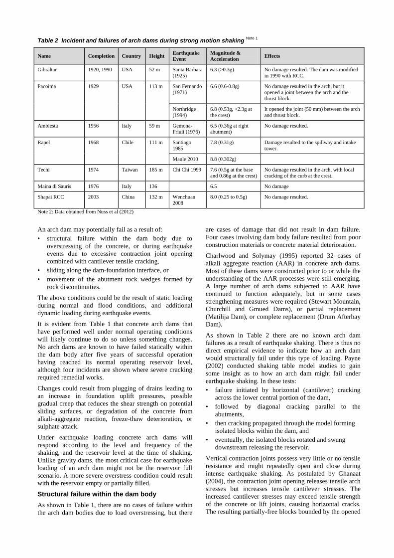
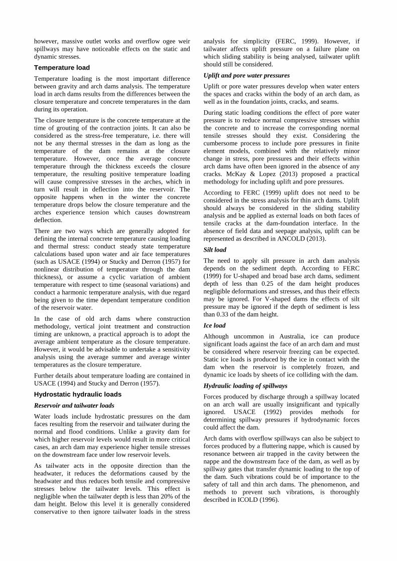
Table 2 Incident and failures of arch dams during strong motion shaking Note 1
Name Completion Country Height Earthquake
Event
Magnitude &
Acceleration Effects
Gibraltar 1920, 1990 USA 52 m Santa Barbara
(1925)
6.3 (>0.3g) No damage resulted. The dam was modified
in 1990 with RCC.
Pacoima 1929 USA 113 m San Fernando (1971)
6.6 (0.6-0.8g) No damage resulted in the arch, but it opened a joint between the arch and the
thrust block.
Northridge
(1994)
6.8 (0.53g, >2.3g at
the crest)
It opened the joint (50 mm) between the arch
and thrust block.
Ambiesta 1956 Italy 59 m Gemona-Friuli (1976)
6.5 (0.36g at right abutment)
No damage resulted.
Rapel 1968 Chile 111 m Santiago
1985
7.8 (0.31g) Damage resulted to the spillway and intake
tower.
Maule 2010 8.8 (0.302g)
Techi 1974 Taiwan 185 m Chi Chi 1999 7.6 (0.5g at the base
and 0.86g at the crest)
No damage resulted in the arch, with local
cracking of the curb at the crest.
Maina di Sauris 1976 Italy 136 6.5 No damage
Shapai RCC 2003 China 132 m Wenchuan
2008
8.0 (0.25 to 0.5g) No damage resulted.
Note 2: Data obtained from Nuss et al (2012)
An arch dam may potentially fail as a result of:
• structural failure within the dam body due to
overstressing of the concrete, or during earthquake
events due to excessive contraction joint opening
combined with cantilever tensile cracking,
• sliding along the dam-foundation interface, or
• movement of the abutment rock wedges formed by
rock discontinuities.
The above conditions could be the result of static loading
during normal and flood conditions, and additional
dynamic loading during earthquake events.
It is evident from Table 1 that concrete arch dams that
have performed well under normal operating conditions
will likely continue to do so unless something changes.
No arch dams are known to have failed statically within
the dam body after five years of successful operation
having reached its normal operating reservoir level,
although four incidents are shown where severe cracking
required remedial works.
Changes could result from plugging of drains leading to
an increase in foundation uplift pressures, possible
gradual creep that reduces the shear strength on potential
sliding surfaces, or degradation of the concrete from
alkali-aggregate reaction, freeze-thaw deterioration, or
sulphate attack.
Under earthquake loading concrete arch dams will
respond according to the level and frequency of the
shaking, and the reservoir level at the time of shaking.
Unlike gravity dams, the most critical case for earthquake
loading of an arch dam might not be the reservoir full
scenario. A more severe overstress condition could result
with the reservoir empty or partially filled.
Structural failure within the dam body
As shown in Table 1, there are no cases of failure within
the arch dam bodies due to load overstressing, but there
are cases of damage that did not result in dam failure.
Four cases involving dam body failure resulted from poor
construction materials or concrete material deterioration.
Charlwood and Solymay (1995) reported 32 cases of
alkali aggregate reaction (AAR) in concrete arch dams.
Most of these dams were constructed prior to or while the
understanding of the AAR processes were still emerging.
A large number of arch dams subjected to AAR have
continued to function adequately, but in some cases
strengthening measures were required (Stewart Mountain,
Churchill and Gmued Dams), or partial replacement
(Matilija Dam), or complete replacement (Drum Afterbay
Dam).
As shown in Table 2 there are no known arch dam
failures as a result of earthquake shaking. There is thus no
direct empirical evidence to indicate how an arch dam
would structurally fail under this type of loading. Payne
(2002) conducted shaking table model studies to gain
some insight as to how an arch dam might fail under
earthquake shaking. In these tests:
• failure initiated by horizontal (cantilever) cracking
across the lower central portion of the dam,
• followed by diagonal cracking parallel to the
abutments,
• then cracking propagated through the model forming
isolated blocks within the dam, and
• eventually, the isolated blocks rotated and swung
downstream releasing the reservoir.
Vertical contraction joints possess very little or no tensile
resistance and might repeatedly open and close during
intense earthquake shaking. As postulated by Ghanaat
(2004), the contraction joint opening releases tensile arch
stresses but increases tensile cantilever stresses. The
increased cantilever stresses may exceed tensile strength
of the concrete or lift joints, causing horizontal cracks.
The resulting partially-free blocks bounded by the opened

contraction joints and cracked lift joints may become
unstable and cause failure of the dam (see Figure 1).
Figure 1 Rotation of blocks caused by cracking and opening of contraction joints (Ghanaat, 2004)
Dam-foundation interface failure
The dam-foundation interface includes the concrete-rock
contact, the concrete immediately above up to about the
first lift joint, and the foundation rock typically 1 to 2 m
immediately below the contact.
There are three types of potential sliding instability cases
at the dam-foundation interface, i.e. sliding along the
contact between the dam concrete and foundation rock,
within the concrete along lift joints, and along planes
immediately below the contact.
Sliding instability for the first two cases are less likely
because of the wedging produced by arch action and
embedment of the structure into the rock. However, arch
dams with relatively flat abutment slopes, or arch dams
with abutment thrust blocks supported by rock
foundations with inadequate shear strength, could be
susceptible to sliding along the foundation contact or
along planes immediately below the contact, in either or
both the arch and downstream directions.
Severe earthquake shaking could break the bond between
the dam and foundation, or cause movement along planes
below the contact, especially if the foundation was not
excavated to radial lines and the excavation surfaces dip
downstream on sections cut radial to the dam axis.
Resulting sliding and rotation at the base could lead to
loss of arch action and subsequently to instability.
Foundation failure
Actual arch dam failures have resulted from foundation
deficiencies, which included sliding of large blocks
bounded by geologic discontinuities within the foundation
and abutments, or along planes of weakness (three failure
cases and three incidents shown in Table 1).
Although no arch dam foundations are known to have
failed because of earthquake shaking, they have not been
subjected to unprecedented seismic design loads.
The most critical mode of foundation instability involves
sliding on discontinuities (joints, faults, shears, bedding
planes, foliation, clay seams, shale beds etc.) within the
foundation. Sliding in the foundation typically occurs
along a single failure plane (plane sliding) or along the
line of intersection of two of these planes (wedge sliding).
To be kinematically capable of failure, the direction of
sliding surfaces must intersect or "daylight" a free surface
downstream from the dam. While it might be capable of
bridging a small unstable foundation block at the bottom,
large, unstable wedges of rock in the abutments could
endanger the safety of the arch dam.
For thin arch dams, sufficient movement may be
generated in the foundation during the shaking to cause
rupture of the dam body. Even if movement initiates but
does not cause dam failure, water forces acting on the
block planes may still increase as a result of the
movement. Stability analyses simulating post-earthquake
conditions are thus required to assess the likelihood of
post-earthquake instability.
Overtopping failure
During large floods the arch wall could be subject to
overtopping and erosion of the abutments. Table 1
includes one such case where overtopping erosion at the
contact zone resulted in sliding failure.
Although no arch dams are known to have failed statically
due to overstressing within the dam body, a possibly more
serious condition occurs when there is an abutment
foundation block upon which the dam rests, that could
erode due to overtopping flows, or become unstable under
increased loading due to the flood conditions.
The loss of part of the abutment and foundation near or at
the toe of the arch wall could enable plane or wedge
sliding by exposing (daylighting) sliding planes, by
removing passive resisting rock, or by changing the
deformations of the dam and redistribution of stress state
at the region and applying more forces to the wedge.
It is important to perform abutment stability analyses
under flood loading considering the increase in dam thrust
on the foundation blocks and the increased hydrostatic
forces on the block bounding planes.
Existing design references
A number of internationally recognised design guidelines
and manuals applicable to arch dams have been published
since 1953, as listed below. This list is not exhaustive and
several other guidelines and manuals could be applied to
arch dams, e.g. regarding site investigations, spillways,
outlet works and dam safety management practices.
United States Bureau of Reclamation
• Guide for Preliminary Design of Arch Dams (1977)
• Design of Arch Dams (1977)
• Design Criteria for Concrete Arch and Gravity Dams
(1977)
• Guidelines on Foundation and Geotechnical Studies
for Existing Concrete Dams (1999)
• State-of-Practice for the Nonlinear Analysis of
Concrete Dams at the Bureau of Reclamation (2006)
United States Army Corps of Engineers
• Arch Dam Design, EM 1110-2-2201 (1994)

• Response Spectra and Seismic Analysis for Concrete
Hydraulic Structures, EM 1110-2-6050 (1999)
• Time-History Dynamic Analysis of Concrete
Hydraulic Structures, EM 1110-2-6051 (2003)
• Stability Analysis of Concrete Structures,
EM 1110-2-2000, (2005)
• Earthquake Design and Evaluation of Concrete
Hydraulic Structures, EM 1110-2-6053 (2007)
Reclamation and USACE have also prepared the
following joint publication:
• Best Practices in Dam and Levee Safety Risk
Assessment, Chapter 21 – Risk Analysis for Concrete
Arch Dams, (2010)
United States Federal Energy Regulation Commission
• Engineering Guidelines for the Evaluation of
Hydropower Projects, Chapter 11 – Arch Dams (1999)
ANCOLD
ANCOLD has no publications specifically for arch dams;
however ANCOLD (1998) contains guidance related to
earthquake design of arch dams, while ANCOLD (2013)
contains information that could be applied to materials
and load conditions for concrete dams in general.
The remainder of this paper draws to a large extent on the
information provided in the above references.
Material parameters
Reclamation, USACE, FERC and ANCOLD all have
similar approaches in defining material properties and
they often refer to the same past studies and reports for
typical values.
The material parameters for both the dam wall and
foundations are project and site specific. Due to limited
space this paper cannot discuss this topic in sufficient
detail and the reader is therefore referred to the extensive
coverage of this topic in the design references listed in the
previous section. However, it is emphasised that a
thorough knowledge must first be gained on a dam's
original design and its performance history and records, to
provide a basis for evaluation and any further studies and
investigations that might be required.
The dam and foundation material parameters should be
determined on the basis of field and laboratory
investigations. In assigning strength and stiffness
parameters for the foundations, it is essential to firstly
derive a proper geological model for the foundations. This
should be undertaken by a geologist with assistance where
appropriate, by a rock mechanics expert. In most cases,
the required parameters will be determined by rock
defects rather than by the rock mass.
Where the field or laboratory determination of certain
material parameters is neither cost effective nor
conclusive, the parameters can be estimated by existing
correlation relations or using the same parameters in
similar projects. In these cases, their effects on the dam
response should be evaluated by parameter sensitivity
analyses. The USA Electric Power Research Institute
investigated the factors that influence uplift pressure
distributions in concrete dams and foundations, to
establish ranges of shear and tensile strengths and
cohesion values typical of concrete (parent concrete,
bonded and unbonded joints), and concrete to rock
interfaces (EPRI, 1992). In the absence of site specific
testing, this document provides valuable information.
The determination of the condition of the lift joints and
the overall strength of the dam based on limited available
testing remains a challenge for dam engineers. Over the
last 50 years Reclamation has performed strength and
frictional tests on numerous concrete dams of different
ages, with construction dates ranging from 1905 to 1993.
Dolen (2011) processed the data of these tests and
reported on the strength and frictional properties of parent
concrete and lift joints, grouping the results by dam ages.
In the absence of site specific information this data
provides valuable information to understanding the joint
strength in relation to construction practices over the
years.
Dolen presented ratios of bonded to unbonded lift joints
for dams of different ages. A practical approach to
account for the portion of lift joints that are not bonded in
the global lift strength properties, as proposed by Dolen,
consists of reducing the average test values based on the
estimated fraction of bonded lift joints.
Loads
General
Reclamation, USACE, FERC and ANCOLD all have the
same design loads and generally the same definitions,
although some of the references define the load types in
more detail.
Arch dams are designed for the same loads as gravity
dams with the exception of the temperature load which
has a significant influence in arch dam design.
The loads for which arch dams must be designed can be
categorized as static or dynamic loads. Static loads are
sustained loads that do not change, or change very slowly
compared to the natural periods of vibration of the
structure, e.g. dead load, hydraulic load, loading from silt
and backfill materials, dynamic forces from flowing water
changing direction, uplift, forces from ice expansion or
impact, and stresses caused by temperature changes.
Dynamic loads are transitory in nature and typically
seconds in duration, e.g. earthquake-induced forces, blast-
induced forces, fluttering nappe forces, or forces caused
by the impact of ice, debris, or boats. Because of the
speed at which they act, the inertial and damping
characteristics of the dam as well as its stiffness affect the
dam's behaviour.
Dead load
Dead load includes the weight of both the concrete and
appurtenant structures (gates, bridges, and outlet works).
The dead load is normally imposed on cantilever
monoliths prior to the grouting of the contraction joints
(no arch action) and should be taken into account when
analysing an arch dam, which is different to applying the
self weight of a gravity dam. The weight of appurtenances
is typically negligible compared to the dam itself;
however, massive outlet works and overflow ogee weir
spillways may have noticeable effects on the static and
dynamic stresses.
Temperature load
Temperature loading is the most important difference
between gravity and arch dams analysis. The temperature
load in arch dams results from the differences between the
closure temperature and concrete temperatures in the dam
during its operation.
The closure temperature is the concrete temperature at the
time of grouting of the contraction joints. It can also be
considered as the stress-free temperature, i.e. there will
not be any thermal stresses in the dam as long as the
temperature of the dam remains at the closure
temperature. However, once the average concrete
temperature through the thickness exceeds the closure
temperature, the resulting positive temperature loading
will cause compressive stresses in the arches, which in
turn will result in deflection into the reservoir. The
opposite happens when in the winter the concrete
temperature drops below the closure temperature and the
arches experience tension which causes downstream
deflection.
There are two ways which are generally adopted for
defining the internal concrete temperature causing loading
and thermal stress: conduct steady state temperature
calculations based upon water and air face temperatures
(such as USACE (1994) or Stucky and Derron (1957) for
nonlinear distribution of temperature through the dam
thickness), or assume a cyclic variation of ambient
temperature with respect to time (seasonal variations) and
conduct a harmonic temperature analysis, with due regard
being given to the time dependant temperature condition
of the reservoir water.
In the case of old arch dams where construction
methodology, vertical joint treatment and construction
timing are unknown, a practical approach is to adopt the
average ambient temperature as the closure temperature.
However, it would be advisable to undertake a sensitivity
analysis using the average summer and average winter
temperatures as the closure temperature.
Further details about temperature loading are contained in
USACE (1994) and Stucky and Derron (1957).
Hydrostatic hydraulic loads
Reservoir and tailwater loads
Water loads include hydrostatic pressures on the dam
faces resulting from the reservoir and tailwater during the
normal and flood conditions. Unlike a gravity dam for
which higher reservoir levels would result in more critical
cases, an arch dam may experience higher tensile stresses
on the downstream face under low reservoir levels.
As tailwater acts in the opposite direction than the
headwater, it reduces the deformations caused by the
headwater and thus reduces both tensile and compressive
stresses below the tailwater levels. This effect is
negligible when the tailwater depth is less than 20% of the
dam height. Below this level it is generally considered
conservative to then ignore tailwater loads in the stress
analysis for simplicity (FERC, 1999). However, if
tailwater affects uplift pressure on a failure plane on
which sliding stability is being analysed, tailwater uplift
should still be considered.
Uplift and pore water pressures
Uplift or pore water pressures develop when water enters
the spaces and cracks within the body of an arch dam, as
well as in the foundation joints, cracks, and seams.
During static loading conditions the effect of pore water
pressure is to reduce normal compressive stresses within
the concrete and to increase the corresponding normal
tensile stresses should they exist. Considering the
cumbersome process to include pore pressures in finite
element models, combined with the relatively minor
change in stress, pore pressures and their effects within
arch dams have often been ignored in the absence of any
cracks. McKay & Lopez (2013) proposed a practical
methodology for including uplift and pore pressures.
According to FERC (1999) uplift does not need to be
considered in the stress analysis for thin arch dams. Uplift
should always be considered in the sliding stability
analysis and be applied as external loads on both faces of
tensile cracks at the dam-foundation interface. In the
absence of field data and seepage analysis, uplift can be
represented as described in ANCOLD (2013).
Silt load
The need to apply silt pressure in arch dam analysis
depends on the sediment depth. According to FERC
(1999) for U-shaped and broad base arch dams, sediment
depth of less than 0.25 of the dam height produces
negligible deformations and stresses, and thus their effects
may be ignored. For V-shaped dams the effects of silt
pressure may be ignored if the depth of sediment is less
than 0.33 of the dam height.
Ice load
Although uncommon in Australia, ice can produce
significant loads against the face of an arch dam and must
be considered where reservoir freezing can be expected.
Static ice loads is produced by the ice in contact with the
dam when the reservoir is completely frozen, and
dynamic ice loads by sheets of ice colliding with the dam.
Hydraulic loading of spillways
Forces produced by discharge through a spillway located
on an arch wall are usually insignificant and typically
ignored. USACE (1992) provides methods for
determining spillway pressures if hydrodynamic forces
could affect the dam.
Arch dams with overflow spillways can also be subject to
forces produced by a fluttering nappe, which is caused by
resonance between air trapped in the cavity between the
nappe and the downstream face of the dam, as well as by
spillway gates that transfer dynamic loading to the top of
the dam. Such vibrations could be of importance to the
safety of tall and thin arch dams. The phenomenon, and
methods to prevent such vibrations, is thoroughly
described in ICOLD (1996).

Hydrodynamic hydraulic loads
As the dynamic interaction that occurs between the
reservoir and the dam during an earthquake can have a
significant effect on the earthquake response of the dam,
it must be considered in the dynamic analysis. Because
the inertia force of a structure is a function of acceleration
and mass, hydrodynamic interaction has a larger influence
on thinner, less massive dams. There are three
formulations for modelling hydrodynamic interaction:
• use of lumped mass (e.g. determined using the
Generalised Westergaard theory of added mass to
model incompressible fluid);
• incompressible fluid finite element equivalent added
mass; and
• compressible fluid added mass, added damping and
added forces with and without reservoir absorption.
Westergaard’s theory of added mass, as developed in
1931, is reasonably appropriate only when assuming
incompressible reservoir acting on a rigid straight gravity
dam perpendicular to a wide valley, and with a vertical
upstream face. For curved surfaces like arch dams, a
Generalized Westergaard Method accounts for dam
curvature and dam flexibility (Kuo, 1982). This method
assumes that the hydrodynamic pressure at any point on
the upstream face is proportional to the total acceleration
acting normal to the dam at that point. The application of
the Generalised Westergaard method is described in more
detail in FERC (1999) and Reclamation (2006).
Incompressible fluid formulations ignore the
compressibility of water and assume the reservoir floor
and the upstream extent of the reservoir are rigid and
ignore accelerations at these locations. Thus, the pressures
induced on the dam from accelerations applied to the
reservoir bottom are ignored.
Modern finite element analysis (FEA) software
incorporates compressible water effects, which model the
interaction between dam and reservoir and the proper
transmission of pressure waves in the upstream-
downstream direction. The use of compressible water
effects is described in USACE (1999 & 2003) and
Reclamation (2006).
Fluid elements are used to model the reservoir-dam and
reservoir-foundation interaction more accurately. A three-
dimensional mesh of fluid elements is developed to
represent the reservoir. The use of fluid elements is
described in Reclamation (2006).
Earthquake load
Arch dams are expected to respond linearly under the
Operational Basis Earthquake (OBE), assuming
continuous monolithic action along the entire length of
the dam. If damage did occur, it should be possible to
repair it while the dam remains operational.
The SEE (Safety Evaluation Earthquake, to replace
Maximum Design Earthquake in the update of the
ANCOLD (1998) guidelines) is the highest adopted
magnitude the dam is required to withstand. The dam is
allowed to respond nonlinearly and suffer significant
damage, but without a catastrophic failure. The SEE to be
used in the analysis of arch dams is defined in ANCOLD
(1998), which is currently under review.
For preliminary linear response spectra analysis, site-
specific response spectra of earthquake ground motions
should be developed by experienced seismologists. The
spectra should be developed for 5% damping, and
relationships or factors provided to obtain response
spectra for higher damping ratios (as high as 10%) if
required for the analysis. These relationships or factors
may be based on a documented site-specific study;
alternatively, the relationships presented by Newmark and
Hall (1982) may be used.
For more detailed linear and non-linear time-history
analysis, acceleration time histories of ground motions
should be developed consistent with the latest guidelines
as for example contained in FERC (1999) and USACE
(2003). Acceleration time histories should be developed
for three components of motion (two horizontal and one
vertical). Time histories may be either (a) recorded or
simulated-recorded time histories or (b) response
spectrum matched time histories. For recorded or
simulated-recorded time histories, a minimum of three
sets of recordings should be used.
Recorded earthquake ground motions at Pacoima Dam
during the 1994 Northridge earthquake indicated that the
seismic input for arch dams might vary along the dam
foundation interface. At present time scarcity of data
prevents a realistic definition of such non-uniform free-
field motions for arch dams, even though procedures for
handling non-uniform input have been developed. In view
of these difficulties, the use of standard uniform seismic
input is currently still acceptable.
Loading Combinations
Arch dams are designed for two groups of loading
combinations. The first group combines all the static
loads and the second group takes into account the effects
of earthquake. In addition, depending on the probability
of occurrence of the cases in each group, they are
categorised as Usual, Unusual, and Extreme loading
combinations.
Table 3 on the next two pages presents a summary of the
static and dynamic loading combinations used by
Reclamation, USACE, FERC and ANCOLD, including
the loading combination categories. Although having a
similar approach, they differ with regard to categorising
certain loading combinations. The designer should
however assess each load case to ensure that it is
applicable to the project and that it is properly classified
under one of the three categories.

Table 3 Summary of loading combinations Note 1
USACE (1994) Reclamation (1977 & 2006) FERC (1999) ANCOLD (1998) Note 2 ANCOLD (2013) Note 2 Proposed for arch dams
Static Usual
D + Tw + Hx + U
D + Ts + Hx + U
D + Hn+ Tx + U
Reclamation (2006):
D + Hn+ Tw + U
D + Hn+ Ts + U
Reclamation (1977):
D + Tw + Hx + S + I + U
D + Ts + Hx + S + U
D + Hn+ Tx + S + I + U
D + Hl + Tx + S + I + U
D + Tw + Hx + S + I + U
D + Ts + Hx + S + U
D + Tw + Hn+ S/B + I + U
D + Ts + Hn+ S/B + U
PQ: D + Hn+ S/B + U + I
D + Hn+ S/B + U + I
D + H50 + S/B + U
D + Tw + Hx + S/B + U + I
D + Ts + Hx + S/B + U
(If Hx is uncertain, check for Hl and Hf.)
D + H50 + Tx + S/B + U
D + Hn+ Tx + S/B + U + I
Static Unusual
D + Hs + Tx + U Note 3
D + Hl + Tx + U Note 4
D + He + Tx + U Note 4
Reclamation (2006):
D + Hl + Ts + U Note 4
D + Hf + Tw + U
Reclamation (1977):
D + Hf + Tx + U
D + Hl + Tx + S + U Note 4
D + He + Tx + S + U Note 4
D + Ts + Hf + S + U
D + Tw + Hf + S + I + U
D + Tx + Hf + S + I + U
D + Tw + Hf + S/ B + U
D + Ts + Hf + S/B + U
D + H500-H2000 + S/B + U
PQ: D + H50 + S/B + U
D + H100 + S/B + Ubd
D + H100 (1 gate closed) + S/B + U
D + H100 + S/B + U + Wind seiche
and wave action
D + H500-H2000 + Tx + S/B + U
PQ: D + H50 + Tx + S/B + U
D + H100 + Tx + S/B + Ubd
D + H100 (1 gate closed) + Tx + S/B + U
D + H100 + Tx + S/B + U + Wind seiche
and wave action
D + Hl / He + Tx + S/B + U Note 4
Static Extreme
D + Hf + Tx + U D + Hf + S/B + U + I
D + H100(>1 gate closed) + S/B + U
D + Hlw + S/B + U
D + Hf + Tx + S/B + U + I
D + Hf + Tw + S/B + U + I
D + Hf + Ts + S/B + U + I
D + H100(>1 gate closed) + Tx + S/B + U
D + Hlw + Tw + S/B + U
Dynamic Unusual
OBE + D + Hn+ Tx + U
OBE + D + He + Tx + U
OBE + D + Tw + Hn+ S/B + I + U
OBE + D + Ts + Hn+ S/B + U
OBE + D + Tw + He+ S/B + I + U
OBE + D + Ts + He+ S/B + U
OBE + D + Hc + S/B + U OBE + D + Hn+ Tw + S/B + U
OBE + D + Hn+ Ts + S/B + U
OBE + D + He / Hl + Tw + S/B + U
OBE + D + He / Hl + Ts + S/B + U

Table 3 continued
USACE (1994) Reclamation (1977 & 2006) FERC (1999) ANCOLD (1998) Note 2 ANCOLD (2013) Note 2 Proposed for arch dams
Dynamic Extreme
SEE + D + Hn + Tx + U Reclamation (2006):
SEE + D + Hn + Tc + U
SEE + D + Hn + Tw + U
SEE + D + Hn + Ts + U
Reclamation (1977):
SEE + D + Tw + Hx + S + I + U
SEE + D + Ts + Hx + S + U
SEE + D + Hn + Tx + S + I + U
SEE + D + Hl + Tx + S + I + U
SEE + D + Tw + Hx + S + I + U
SEE + D + Ts + Hx + S + U
SEE + D + Hc + S/B + U SEE + D + Hn+ S/B + U SEE + D + Hn+ Tw + S/B + U
SEE + D + Hn+ Ts + S/B + U
SEE + D + He / Hl + Tw + S/B + U
SEE + D + He / Hl + Ts + S/B + U
Hn: Usual (normal) reservoir level with associated tailwater level H50: 1in 50 AEP reservoir level with associated tailwater level Tx: Temperature at the time D: Dead load including appurtenances
Hx: Reservoir level at the time with associated tailwater level H100: 1in 100 AEP reservoir level with associated tailwater level Ts: Summer temperature U: Uplift
Hl: Lowest operating reservoir level with associated tailwater level H500: 1in 500 AEP reservoir level with associated tailwater level Tw: Winter temperature Ubd: Uplift with blocked drains
He: Empty reservoir level with no tailwater level H2000: 1in 2000 AEP reservoir level with associated tailwater level S: Silt (if applicable)
Hc: Critical reservoir level with associated tailwater level B: Backfill against dam (if applicable)
Hf: Maximum flood reservoir level with associated tailwater level I: Ice (if applicable)
Hlw: Landslide generated wave reservoir level with normal tailwater level PQ: Post earthquake
Notes:
1. This table contains a collation of loading combinations proposed by the respective publications. Not all the cases would apply to a specific dam and the design should use judgement in selecting the
combinations and categorising them.
2. The combinations for ANCOLD (1998) and ANCOLD (2013) were developed for gravity dams and are included here with the view to achieve proposed combinations for arch dams that are reasonably
consistent with these ANCOLD guidelines.
3. This case applies only to dams that are normally at a low level or empty, such as flood retention dams.
4. For flood retention dams these cases should be considered under Usual Static.
5. Uplift should be determined by the reservoir level and tailwater level taking into account any foundation drains.
6. Silt, backfill against the dam and ice should be included only if applicable.

Table 4 Summary of factors of safety
Parameter USACE
(1994)
Reclamation
(1977 & 2006) FERC (1999)
ANCOLD
(1998) Note 1
ANCOLD
(2013) Note 1
Range
Proposed for
arch dams
Static Usual
Compression 4.0
3.0-not more
than 10.3 MPa
(4.0) Note 2
2.0 4.0 3.3 2.0-4.0 3.3
Tension 1.0 Not more than
1.03 MPa 1.0 1.0 1.0 1.0 1.0
Sliding 2.0 3.0 1.5 (2.0) Note 3
1.5 – 2.0 1.5 / 2.0 / 3.0 Note 4
1.3-3.0 1.5 / 2.0 / 3.0 Note 4
Static Unusual
Compression 2.5
2.0 not more than 15.5 MPa
(2.7) Note 2
1.5 2.7 2.0 1.5-2.7 2.0
Tension 1.0 Not more than
1.55 MPa 1.0 1.0 1.0 1.0 1.0
Sliding 1.3 2.0 1.5 1.3 – 1.5 1.3 / 1.5 / 2.0 Note 4
1.3-2.0 1.3 / 1.5 / 2.0 Note 4
Static Extreme (maximum flood condition only)
Compression 1.5 Note 5
Note 5
Note 5
1.3 1.3-1.5 2.0
Tension 1.0 Note 5
Note 5
Note 5
1.0 1.0 1.0
Sliding 1.1 Note 5
Note 5
Note 5
1.1 / 1.3 / 1.5 Note 4
1.1-1.5 1.3 / 1.5 / 2.0 Note 4
Dynamic Unusual (cases including OBE)
Compression 2.5
2.0 not more than 15.5 MPa
(2.7) Note 2
- 2.7 2.0 2.0-2.7 2.0
Tension 1.0 Not more than
1.55 MPa - 1.0 1.0 1.0 1.0
Sliding 1.3 2.0 - 1.3 – 1.5 1.3 / 1.5 / 2.0 Note 4
1.3-2.0 1.3 / 1.5 / 2.0 Note 4
Dynamic Extreme (cases including SEE)
Compression 1.5 1.0 (1.3) Note 2
1.1 1.3 1.3 1.1-3.0 1.3
Tension 1.0 1.0 1.0 1.0 1.0 1.0 1.0
Sliding 1.1 1.0 1.1 1.2 – 1.4 1.1 / 1.3 / 1.5 Note 4
1.0-1.5 1.1 / 1.3 / 1.5 Note 4
Notes:
1. These guidelines were developed for gravity dams.
2. Values in brackets are for the foundations.
3. Value in brackets is for internal shear.
4. Factors are for “Residual strength c’ and ’ well-defined” / “Peak strength c’ and ’ well-defined” / “Peak strength c’ and ’ not well-defined” (refer ANCOLD (2013) for further explanation of these conditions).
5. These references included maximum flood in the static unusual category.
6. The factor of safety for allowable tensile strength should be applied to the concrete under consideration, i.e. either the parent or lift joint strength.
Acceptance criteria
The structural integrity of an arch dam is maintained and
it is considered safe if overstressing, sliding and other
possible modes of failure will not occur.
Reclamation, USACE, FERC and ANCOLD differ
slightly in the values assigned to determine the allowable
stresses and the factors of safety against sliding.
Table 4 presents the factors of safety used by each of the
organisations for the allowable stresses and stability. This
table also includes the factors suggest by the authors of
this paper when assessing arch dams in accordance with
ANCOLD guidelines, as further discussed below.
Allowable stress
The ultimate load-resisting capacity of an arch dam is
determined by the compressive strength of the concrete,
unless foundation or another mode of failure occurred
first. The tensile strength of the concrete is however an
important consideration, particularly in estimating seismic
safety of concrete arch dams.
As discussed by Gillan et al (2011) the general stress-
strain behaviour of concrete can be characterized in four
stages:
• In the first stage the stress-strain curve is considered
to be linear elastic, i.e. there would be no permanent
deformation. According to ACI (1996) mass concrete
material behaves linearly up to approximately 35 % of
the ultimate strength.
• In the second stage the stress-strain curve consists of
some inelastic behaviour (cracking). The load would
result in minor permanent deformations and strains in
the material. According to ACI (1996) the growth of
internal microcracks commences in the concrete at

loads equal to approximately 35 to 50 % of the
ultimate strength.
• The third stage consists of large inelastic strains, so
that there is a noticeable change in deformation. In
this stage there is stable crack growth in the concrete,
meaning that cracks will form but not initiate failure.
• The fourth stage is the fracture stage where
deformations are great enough to produce unstable
crack grow and eventual failure of the concrete.
The above mentioned concrete behaviour was considered
when comparing the factors of safety given in the existing
references and suggesting factors to be adopted for arch
dams. For load combinations in the Static Usual category
it is assumed that the concrete behaviour is limited to the
linear elastic first stage and a factor of safety for
compressive strength of 3 would be appropriate, with 3.3
adopted in ANCOLD (2013). Compared to the factors
used provided in the references by USACE, Reclamation
and FERC, the same factors as used in ANCOLD (2013)
is suggested for arch dams.
For the less frequent load combinations in the Static
Unusual, Static Extreme and Dynamic Unusual categories
it is assumed that the concrete behaviour is limited to the
second stage, which can result in microcracking and
minor permanent deformations and strains in the concrete
that would not affect the operation of the dam. Therefore,
a factor of safety for compressive strength of 2 to 3 would
be appropriate, with 2.0 adopted in ANCOLD (2013).
Compared to the factors provided in the references by
USACE, Reclamation and FERC, the same factors as
used in ANCOLD (2013) is suggested for arch dams,
except for the Static Extreme category, as discussed in the
second paragraph below.
For the rare load combinations in the Dynamic Extreme
category (SEE) it was assumed that the concrete
behaviour is limited to the third stage. This assumes that
the concrete may crack and experience permanent
deformations and damage due to the load, but not enough
to cause failure. A factor of safety for compressive
strength of 1.1 would be appropriate, with 1.3 adopted in
ANCOLD (2013). Compared to the factors provided in
the references by USACE, Reclamation and FERC, the
same factors as used in ANCOLD (2013) is suggested for
arch dams.
ANCOLD (2013) adopted only one set of criteria for the
Extreme category, which includes both the maximum
design flood and the maximum safety evaluation
earthquake, although they relate to the static and dynamic
strength parameters respectively. This implies that for the
flood load condition concrete behaviour is allowed
beyond the second stage, i.e. in the third stage which
includes cracking and permanent deformation. Whereas
the SEE loading is a cyclic loading, the extreme flood
condition is a sustained loading. The authors believe that
the factors in ANCOLD (2013) for the flood loading
condition (Static Extreme) may be too low and the
allowable behaviour of the concrete should be limited to
the second stage for which the factor of safety for
compressive strength of 2 to 3 would be appropriate.
In Table 4 for all the cases the factor of safety for
allowable tensile stress is unity. The intent of any design
should be to minimize or limit tensile stresses to localized
areas by reshaping and / or redesigning the dam. A dam
designed with high tensile stresses in too many areas,
even though within the allowable limits, might exceed the
compressive limits under one or more loading
combinations. When the tensile strength of the concrete is
exceeded and cracking occurs, the uncracked portion of
the cantilever would tend to carry more compression
while also increasing the balance of the loads carried by
the arches. If the cracking becomes widespread, too much
of the load would have to be carried by the arches. The
uncracked portion of the cantilevers could exceed the
compressive strength of the concrete and cause crushing
failure of the concrete. Subsequent joint opening and
cracking and load redistributions might eventually
exhaust the capacity of the concrete, or might form
surfaces along which partial sliding could occur.
Therefore, since compression is the dominant mode of
failure of an arch dam, and since the other concrete
properties are a function of the compressive strength, a
more conservative approach is taken in establishing the
allowable compressive stresses compared to the allowable
tensile stresses.
Pursuant to the above, one of the objectives in arch dam
design is minimizing the magnitude and the locations of
tension in the dam. Tensile stresses are however inherent
to most arch dams and therefore require further
consideration.
Arch dams typically exhibit tensile stresses at the
downstream face along the foundation under the low
reservoir – high temperature conditions, which includes
the construction period. This condition is regarded as a
significant problem as long as the stability of the
cantilevers is not in question. Even if some cracking has
occurred, the additional hydrostatic load and the resulting
downstream deflection will cause the cracks to close.
Tension at the upstream face of the dam however requires
more careful consideration, due the possibility of a
seepage path through the dam if cracks were to develop
and extend through the thickness of the dam. Cracked
cantilevers do not necessarily imply a dam failure, as
loads carried by the cantilevers before cracking will be
transferred to the arches and adjacent cantilevers. A
nonlinear analysis is required to ensure that the
compressive stresses of the remaining uncracked section
of the cantilever and the other arches and cantilevers
remain within the allowable concrete stresses.
As already mentioned the current engineering guidelines
recommend a factor of safety of 1.0 to determine the
allowable tensile stresses. The authors believe that this
factor should be used with caution and only be used when
extensive testing has been undertaken so that sufficient
statistical data is available to estimate the existing tensile
strength with confidence.
In the absence of tensile strength data of the concrete,
Chopra (1994) suggested that the tensile-compressive
strength relationships determined by Raphael (1984)
could be used if sufficient compressive strength data is
available.

When assessing existing dams with insufficient or no
construction records, the number of tensile strength tests
are usually limited and insufficient to make reliable
statistical correlations. This could lead to overestimating
the existing tensile strength of the concrete when applied
to the entire dam. It is therefore deemed appropriate to
apply a strength reduction factor and assume a lower and
more conservative tensile strength for the entire dam.
The ACI Building Code (ACI, 2008) states that one of the
reasons for strength reduction factors is to account for
potential understrength members due to variations in
material strengths and dimensions. In plain (mass)
concrete, since both flexural tension strength and shear
strength depend on the tensile strength characteristics of
the concrete, with no reserve strength or ductility possible
due to the absence of reinforcement, equal strength
reduction factors for both bending and shear are
considered appropriate. Consequently, ACI suggests a
strength reduction factor of 0.6 for bending and shear,
based on reliability analyses and statistical studies of
concrete properties, as well as calibration against past
practice. A practical approach is therefore to apply the
strength reduction factor of 0.6, as suggested by ACI for
tensile strength in plain concrete, to determine the
existing tensile strength of the concrete when only limited
testing has been undertaken. The factors of safety for
tension as given in Table 4, are then applied to the
reduced tensile strength in order to estimate the allowable
tensile strength.
Stability of cantilevers during construction
As arch dams are constructed in monoliths, because of the
vertical curvature, the monoliths may be unstable against
overturning prior to the grouting of the monolith joints
and the filling of the reservoir. When assessing the
construction phase dam empty case, the stability of the
cantilevers must be assessed to assure that each cantilever
is stable at different stages of construction.
Dynamic loading
Establishing the acceptability of performance of arch
dams under dynamic load cases is a complicated process
which cannot be summarized in a table and is discussed in
the next section under “Analysis methods and
evaluation”. The factors of safety given in Table 4 are
only the first step in determining the safety criteria and
should not be regarded as absolute limits. These factors
should be applied to the test results for the appropriate
rate of loading as indicated by the dynamic analysis, or as
determined for the static analysis and modified according
to the approach discussed by Raphael (1984).
Analysis methods and evaluation
Concrete arch dams are complex three-dimensional shell
structures that rely on both cantilever action (on vertical
planes) and arch action (on horizontal planes) for
transferring the loads to the foundation, which is deemed
to include the entire length of concrete rock interface.
Hence, two dimensional analyses cannot provide realistic
results and the three dimensional geometry of the dam,
foundation and reservoir (if required) has to be considered
in the analysis to provide a more realistic idealisation of
the structural system.
Method of analysis
Three-dimensional finite element analysis is preferred for
the static and dynamic analysis of arch dams. The trial
load method is considered outdated, but may still be used
for preliminary static stress analysis only if the dam has a
simple geometry and uniform material parameters can be
assumed for the concrete and for the foundation rock in a
low hazard area. Other mathematical formulations and
approaches can also be employed, but the accuracy of
such methods should be verified by comparison with the
finite element analyses
With the development of the finite element method, the
advances in dynamic analysis procedures and the
availability of high capacity computers, the older
traditional methods of analysis have been abandoned. The
use of the finite element analysis technique, with its
versatility and capability to deal with structural,
geotechnical and fluid aspects, allowing a more realistic
analysis of virtually any type of dam, has become the
standard practice for dam design and analysis.
Different elements have been used in the past to model
arch dams, including shell elements and solid elements.
Shell elements (with five or six degrees of freedom) are
consistent with the behaviour of the dams; however they
are unable to accurately model stress distribution through
the dam thickness. Therefore, three dimensional
brick/solid elements (with three degrees of freedom) are
now routinely used for the analysis.
Evaluation for static loading
Idealization of the dam and an appropriate portion of the
foundation rock as an assemblage of finite elements is the
first step in a typical finite element static analysis. Each
individual static load case as explained in the previous
sections is applied to the model separately and the results
should be obtained and reviewed to facilitate examination
of the consistency of the results. The load cases are then
combined based on proposed load combinations and
finally the system is solved to determine displacements at
nodal points of the assembled structure, stresses computed
at various locations (such as the Gauss integration points)
and arch thrusts and shears exerted on the dam abutments
and / or thrust blocks.
At each nodal point, three displacement components
corresponding to a global system of axes are computed.
The magnitudes and deflected shapes of the resulting
displacements provide important data that can be used to
visually evaluate the overall behaviour of an existing dam
(or acceptability of a new design), although the
magnitudes of the resulting deformations are not directly
used in safety evaluation of arch dams. The deflection
patterns should vary smoothly from point to point and are
used to evaluate the adequacy of the design/analysis by
visual means.
Since maximum stresses in an arch dam usually occur at
the faces of the structure, normal stresses resolved into
arch, cantilever and principal stresses at the upstream and
downstream faces of the dam are the primary stresses

used for the evaluation of the analysis results. However,
shear stresses induced in the body of the dam by bending
and twisting moments should also be examined to assure
that they are within the allowable limits. The evaluation
of the safety of an existing dam involves comparing the
maximum computed stresses with the allowable
compressive and tensile strengths of the concrete. The
largest compressive and tensile stresses should be less
than the corresponding allowable strengths of the concrete
considering the factors of safety established in Table 4 for
each particular loading combination.
Whenever the overall stresses in the structure are below
the allowable values as specified in the previous sections,
the design is considered to be adequate or the existing
dam is safe from stress distribution through the dam wall
point of view. A well-designed arch dam will develop
only compressive stresses under the static loads and these
are generally much smaller than the allowable
compressive strength of the concrete.
The stress results produced by the linear finite element
analysis usually indicate some areas of tensile stress in the
dam. Whilst tensile strength of the parent concrete could
be high, it should be kept in mind that a typical arch dam
is made of concrete blocks divided by lift joints and
vertical contraction joints, with lower tensile and shear
strengths than the parent concrete (or even a pre-existing
crack with no tensile strength). Therefore it is not
appropriate to evaluate the indicated tensile stresses of a
finite element model in terms of allowable tensile stress
for the parent concrete alone.
If the compressive or tensile stresses in some locations of
the dam predicted by linear elastic analysis exceed the
allowable strengths, they may not reliably predicted the
extent of the cracking (damage) or the true behaviour of
the dam. For these cases, nonlinear response of concrete
dams can be employed to provide a more accurate
response of the dam and the damaged region of the dam.
However, the predictions of the extent of the damage
obtained from these analyses are quite sensitive to the
assumed nonlinear properties of concrete or joints.
Evaluation for seismic loading
There are no codes and regulations which are universally
applicable to the earthquake resistant design of concrete
arch dams. The performance criteria, therefore, should be
discussed on a case-by-case basis.
The earthquake response of an arch dam is assessed
through a staged approach. Usually, the linear response-
spectrum mode-superposition method is used as first
approach, but if maximum stresses exceed the allowable
values, a time-history analysis is required to assess the
severity of joint opening and tensile cracking. The basic
results of a response-spectrum analysis consist of the
maximum nodal displacements and element stresses.
Because the response to the three earthquake components
(two horizontal plus vertical) are developed
independently, the maximum dynamic responses due to
the earthquake components are further combined by the
SRSS method to include the effects of all three
components. It is notable that the resulting dynamic
responses obtained in this manner have no sign and may
be interpreted as being positive (e.g. tensile stress) or
negative (e.g. compressive stress). In the response-
spectrum method, total stresses are estimated by linear
combination of the dynamic stresses with static stresses
due to the usual loading combination and compared with
the allowable values. This method requires a qualitative
judgement of how stresses will be redistributed during
joint opening and cracking. This evaluation is done in lieu
of more prolonged time-history analysis. This approach is
not sufficient for some situations and a more detailed
analysis using time-history techniques may be required.
The evaluation criterion for time-history analysis is more
involved than simple stress checks. As described by
Ghanaat (2004), a systematic interpretation and
evaluation of these results in terms of the stress demand-
capacity ratios, cumulative overstress duration, spatial
extent of overstressed regions, and other considerations
form the basis for an approximate and qualitative estimate
of damage (see Figure 2). This evaluation is applied to the
damage control range of strains. If the estimated level of
damage falls below the acceptance threshold for a
particular dam type, the damage is considered to be low to
moderate and the linear time-history analysis would
suffice. Otherwise the damage is considered to be severe,
requiring a non-linear time-history analysis to determine
whether or not it would lead to failure of the dam.
Horizontal lift joints and vertical contraction joints should
be assumed to crack when subjected to tensile stresses
exceeding their tensile strengths. The dam may be
considered safe for the SEE if, after the effects of crack
and joint opening have been accounted for, it can be
shown that the concrete is not over-compressed and free
cantilevers do not topple.
Figure 2 Illustration of seismic performance and damage criteria (Ghanaat, 2004)
Post-earthquake safety
A post-earthquake safety evaluation is required to assure
the safety of the dam if a damaging SEE should occur, or
the predicted performance of the dam due to a postulated
SEE should indicate substantial damage. This evaluation
should consider the effects of static loads as well as

severe aftershock earthquakes that invariably occur after
any major quake.
Sliding stability
To assure safety against sliding along identified feasible
failure planes in the dam, at the dam-foundation interface,
or in the foundation, the shear friction factor of safety
should higher than those given in Table 4 for normal,
unusual and extreme loading. These safety factors assume
that stability has been evaluated with respect to
conservative shear strength parameters. For major dam
structures subjected to severe seismic loading, time-
history analyses should be considered for abutment and
foundation stability instead of the usual pseudostatic
analyses. In time-history analyses, the factor of safety
varies with time and may become less than 1.0 for one or
more cycles provided that the resulting cumulative sliding
displacement is very small and can be tolerated.
Stability analyses of foundation blocks typically involve
uncoupled analyses whereby loading from the dam is
calculated from finite element analyses and applied in a
separate rigid block foundation analysis. When time-
history rigid block analyses are performed and the factor
of safety drops below 1.0 during the earthquake, the
permanent displacement could be estimated using the
Newmark type method. Such an estimate would be a
conservative worst case displacement since it is assumed
that the loads follow the block as it displaces. In reality,
loads would change direction and be redistributed by the
dam. In certain critical cases, a coupled dam-foundation
analysis may be warranted, but this is not often the case.
Acknowledgement
The authors which to acknowledge Mr Brian Cooper, who
reviewed this paper also from the perspective as a
member of the Working Group that is updating the
ANCOLD (1998) guidelines, and commented as follows:
“I am in general agreement with the principles and
concepts presented in this paper. They are consistent with
what has been written to date, in the revised ANCOLD
earthquake guidelines which covers earthquake analysis
of all concrete dams. There may be some minor
differences in the factors of safety but these will be
worked out as the revised guidelines are further
developed. The revised guidelines are less cook-book and
more guidelines – more along the lines of this paper.”
References
ACI. 1996. Mass Concrete (ACI 207.1R-96). American
Concrete Institute.
ANCOLD. 1998. Guidelines for design of dams for
earthquake. Australian National Committee on Large
Dams.
ANCOLD. 2013. Guidelines on design criteria for
concrete gravity dams. Australian National Committee on
Large Dams.
Charlwood, R. G.; Solymar Z. V. 1995. Long-term
management of AAR-affected structures - an international
perspective. Proceedings of the USCOLD 2nd
International Conference on Alkali-Aggregate Reactions
in Hydraulic Plants and Dams. Chattanooga, Tennessee.
Chopra, A.K. 1994. Earthquake analysis, design and
safety evaluation of concrete arch dams. Proceedings of
the 10th
World Conference on earthquake engineering.
Balkema, Rotterdam.
Dolen, T.P. 2011. Selecting strength input parameters for
structural analysis of aging concrete dams. Proceeding of
the 31st Annual USSD Conference, San Diego, California.
EPRI. 1992. Uplift pressures, shear strengths, and tensile
strengths for stability analysis of concrete gravity dams.
TR-100345 Volume 1. Prepared by Stone and Webster
Engineering Corporation, Denver, Colorado, for Electric
Power Research Institute, Palo Alto, California.
FERC. 1999. Engineering Guidelines for the Evaluation
of Hydropower Projects, Chapter 11 – Arch Dams. US
Federal Energy Regulation Commission, Washington DC.
Gillan, C.; Lund, G.; Weldon, J. 2011. Three predominant
failure modes for thin arch dams. Proceedings of the 31st
Annual USSD Conference. San Diego, California.
Ghanaat, Y. 2004. Failure modes approach to safety
evaluation of dams. Proceedings of the 13th
World
Conference on Earthquake Engineering. Vancouver.
ICOLD. 1996. Vibrations of Hydraulic Equipment for
Dams, Bulletin 102. International Commission on Large
Dams, Paris, France.
ICOLD. 2001. Design Features of Dam to Resist Seismic
Ground Motion, Bulletin 120. International Commission
on Large Dams, Paris, France.
Kuo, J.S.H. 1982. Fluid-Structure Interactions: Added-
mass Computations for Incompressible Fluid, Report No.
UCB/EERC-82/09. University of California Earthquake
Engineering Research Center, Berkeley, California.
McKay, M.; Lopez, F. 2013. Practical methodology for
inclusion of uplift and pore pressures in analysis of
concrete dams, Proceedings of the NZSOLD/ANCOLD
2013 Annual Conference, Rotarua, New Zealand.
Newmark, N.M.; Hall, W.J. 1982. Earthquake Spectra
and Design; Engineering monographs on earthquake
criteria, structural design, and strong motion records -
Vol. 3: Earthquake Engineering Research Institute,
University of California, Berkeley, California.
Nuss, K.N.; Matsumoto, N.; Hansen, K.D. 2012. Shaken
but not stirred – earthquake performance of concrete
dams. Proceedings of the 32nd
Annual USSD Conference.
New Orleans, Louisiana.
Payne, T.L. 2002. Shaking table study to investigate
failure modes of arch dams. Paper reference 145.
Proceedings of the 12th European Conference on
Earthquake Engineering. London.
Reclamation. 1977. Design of arch dams. US Bureau of
Reclamation, Denver, Colorado.
Reclamation. 1977a. Guide for preliminary design of arch
dams. US Bureau of Reclamation. Denver, Colorado.
Reclamation. 1977b. Design criteria for concrete arch
and gravity dams. US Bureau of Reclamation, Denver,
Colorado.

Reclamation. 1999. Guidelines on foundation and
geotechnical studies for existing concrete dams. US
Bureau of Reclamation, Denver, Colorado.
Reclamation. 2006. State-of-practice for the nonlinear
analysis of concrete dams at the Bureau of Reclamation.
US Bureau of Reclamation, Denver, Colorado.
Reclamation and USACE. 2010. Best Practices in Dam
and Levee Safety Risk Assessment, Chapter 21 – Risk
Analysis for Concrete Arch Dams. US Army Corps of
Engineers, Washington DC, and US Bureau of
Reclamation, Denver, Colorado.
Stucky A. and Derron M.H. 1957. Problèmes thermiques
posés par la construction des barrages-réservoirs, École
Polytechnique de Lausanne.
USACE. 1992. Hydraulic design of spillways. Engineer
Manual EM 111-2-1603. US Army Corps of Engineers,
Washington DC.
USACE. 1994. Arch dam design, Engineering Manual
EM 1110-2-2201. US Army Corps of Engineers,
Washington DC.
USACE. 1999. Response Spectra and Seismic Analysis
for Concrete Hydraulic Structures, Engineering Manual
EM 1110-2-6050 (1999). US Army Corps of Engineers,
Washington DC.
USACE. 2003. Time-History Dynamic Analysis of
Concrete Hydraulic Structures, Engineering Manual
EM 1110-2-6051. US Army Corps of Engineers,
Washington DC.
USACE. 2005. Stability Analysis of Concrete Structures,
Engineering Manual EM 1110-2-2000. US Army Corps
of Engineers, Washington DC.
USACE. 2007. Earthquake Design and Evaluation of
Concrete Hydraulic Structures, Engineering Manual
EM 1110-2-6053. US Army Corps of Engineers,
Washington DC.
Westergaard, H. M. Water Pressures on Dams during
Earthquakes. ASCE Transactions, November 1931.


