Evaluation of aberration controllability of the full-field ...
24
October 18, 2011 EUVL Symposium 2011 K. Otaki, T.Yahiro, K.Matsumoto, O.Arai, Y.Kohama and K. Murakami Evaluation of Aberration Controllability of the Full-Field Exposure System
Transcript of Evaluation of aberration controllability of the full-field ...
October 18, 2011
EUVL Symposium 2011
K. Otaki, T.Yahiro, K.Matsumoto, O.Arai, Y.Kohama and K. Murakami
Evaluation of Aberration Controllability of the Full-Field Exposure System
2EUVL Symposium 2011
BackgroundPrinciple of the MetrologyMISTI@UECMISTI@SeleteAberration controllabilityAberration adjustment and verificationSummary
Outline
3EUVL Symposium 2011
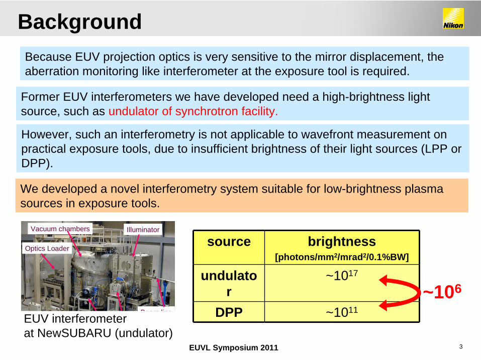
Former EUV interferometers we have developed need a high-brightness light source, such as undulator of synchrotron facility.
source brightness[photons/mm2/mrad2/0.1%BW]
undulato r
~1017
DPP ~1011
~106
Illuminator
Beam line
Vacuum chambers
Vacuum pumps
Optics Loader
However, such an interferometry is not applicable to wavefront measurement on practical exposure tools, due to insufficient brightness of their light sources (LPP or DPP).
We developed a novel interferometry system suitable for low-brightness plasma sources in exposure tools.
EUV interferometerat NewSUBARU (undulator)
Because EUV projection optics is very sensitive to the mirror displacement, the aberration monitoring like interferometer at the exposure tool is required.
Background
4EUVL Symposium 2011
BackgroundPrinciple of the MetrologyMISTI@UECMISTI@SeleteAberration controllabilityAberration adjustment and verificationSummary
Outline
5EUVL Symposium 2011
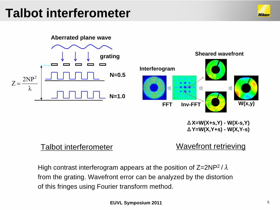
Talbot interferometer
Aberrated plane wave
grating
N=0.5
N=1.0λ
2NPZ2
High contrast interferogram appears at the position of Z=2NP2 /λfrom the grating. Wavefront error can be analyzed by the distortion of this fringes using Fourier transform method.
FFT Inv-FFT
Interferogram
W(x,y)
ΔX=W(X+s,Y) - W(X-s,Y) ΔY=W(X,Y+s) - W(X,Y-s)
Sheared wavefront
Wavefront retrieving
Talbot interferometer
6EUVL Symposium 2011
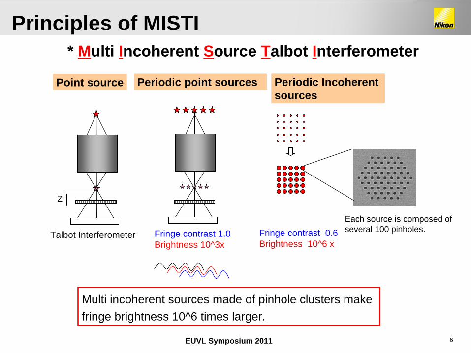
* Multi Incoherent Source Talbot Interferometer
Multi incoherent sources made of pinhole clusters make fringe brightness 10^6 times larger.
Talbot Interferometer Fringe contrast 1.0Brightness 10^3x
Fringe contrast 0.6Brightness 10^6 x
Point source Periodic point sources Periodic Incoherent sources
Z
Each source is composed of several 100 pinholes.
Principles of MISTI
7EUVL Symposium 2011
BackgroundPrinciple of the MetrologyMISTI@UECMISTI@SeleteAberration controllabilityAberration adjustment and verificationSummary
Outline
8EUVL Symposium 2011
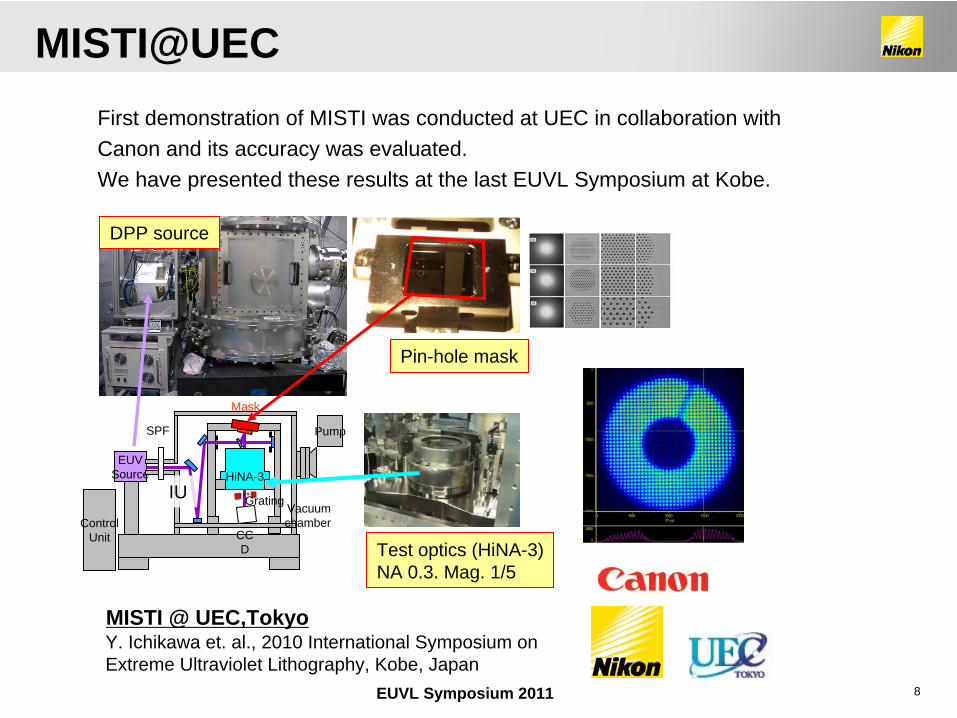
MISTI @ UEC,TokyoY. Ichikawa et. al., 2010 International Symposium on Extreme Ultraviolet Lithography, Kobe, Japan
EUVSource
Pump
ControlUnit
HiNA-3
Vacuumchamber
IU
CC D
Grating
SPF
Mask
Test optics (HiNA-3)NA 0.3. Mag. 1/5
Pin-hole mask
DPP source
First demonstration of MISTI was conducted at UEC in collaboration with Canon and its accuracy was evaluated. We have presented these results at the last EUVL Symposium at Kobe.
MISTI@UEC
9EUVL Symposium 2011
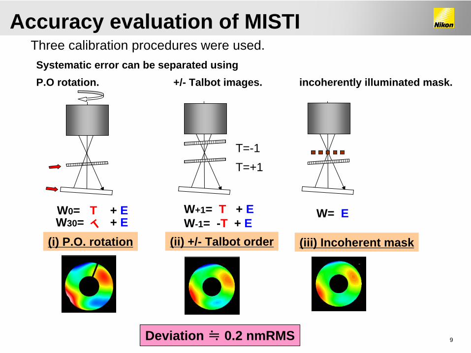
W0= T + EW30= + ET
T=-1T=+1
W+1= T + EW-1= -T + E
(i) P.O. rotation (ii) +/- Talbot order (iii) Incoherent mask
incoherently illuminated mask.
W= E
Deviation ≒ 0.2 nmRMS
+/- Talbot images.Systematic error can be separated usingP.O rotation.
Accuracy evaluation of MISTIThree calibration procedures were used.
10EUVL Symposium 2011
BackgroundPrinciple of the MetrologyMISTI@UECMISTI@SeleteAberration controllabilityAberration adjustment and verificationSummary
Outline
11EUVL Symposium 2011
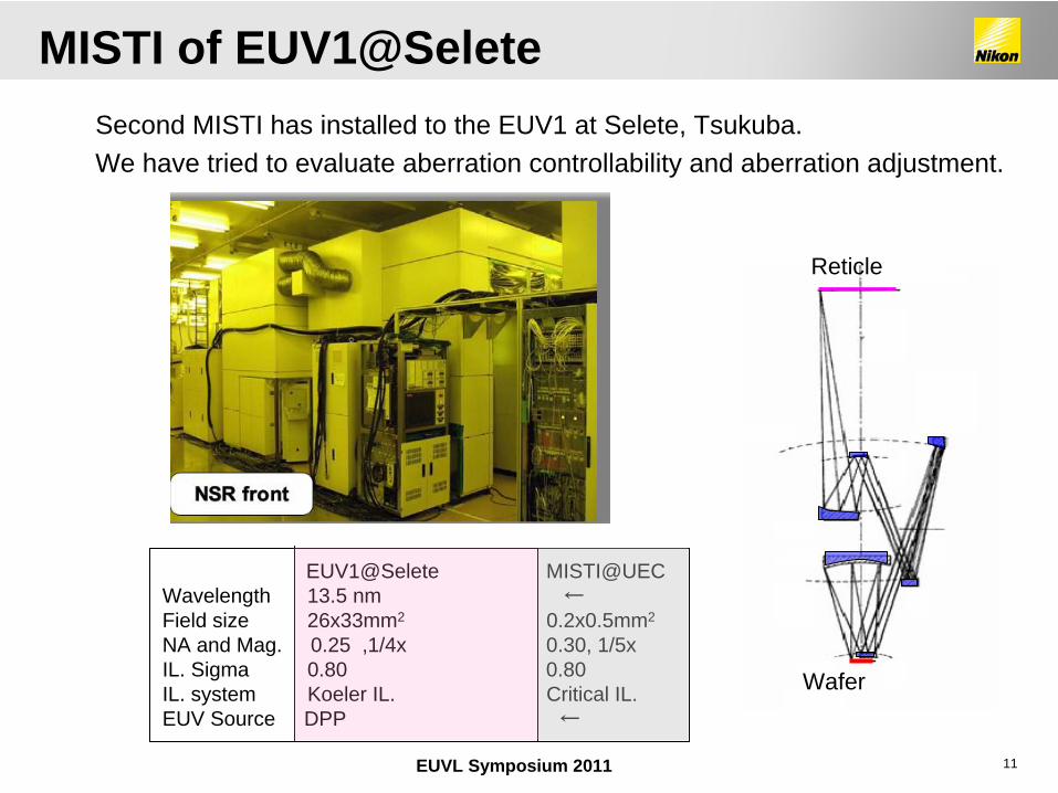
Wafer
Reticle
Second MISTI has installed to the EUV1 at Selete, Tsukuba.We have tried to evaluate aberration controllability and aberration adjustment.
EUV1@Selete MISTI@UECWavelength 13.5 nm ←Field size 26x33mm2 0.2x0.5mm2
NA and Mag. 0.25 ,1/4x 0.30, 1/5xIL. Sigma 0.80 0.80IL. system Koeler IL. Critical IL.EUV Source DPP ←
MISTI of EUV1@Selete
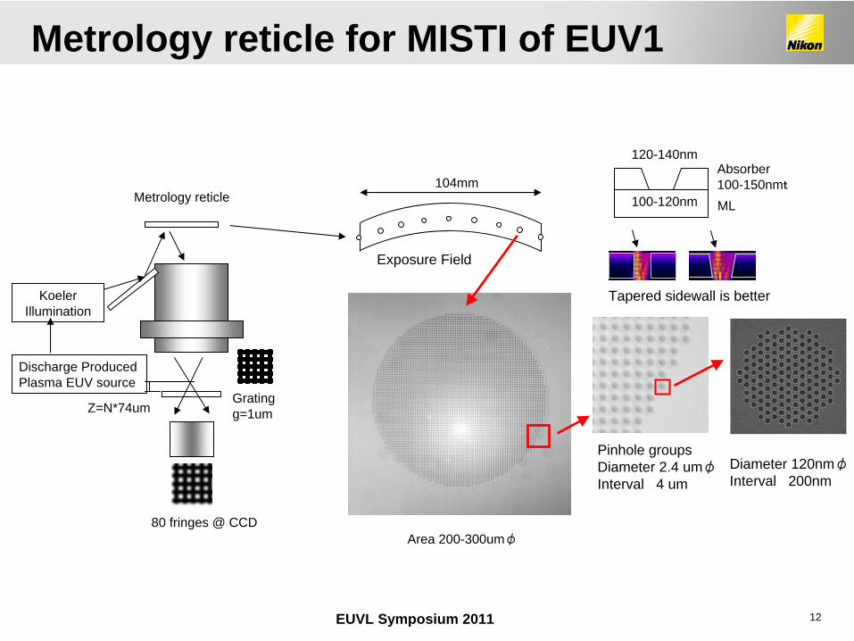
12EUVL Symposium 2011
Diameter 120nmφInterval 200nm
104mm
Exposure Field
Pinhole groupsDiameter 2.4 umφInterval 4 um
120-140nm
100-120nm
Absorber 100-150nmt
ML
Tapered sidewall is better
Metrology reticle
Grating g=1umZ=N*74um
80 fringes @ CCD
Discharge Produced Plasma EUV source
Koeler Illumination
Area 200-300umφ
Metrology reticle for MISTI of EUV1
13EUVL Symposium 2011
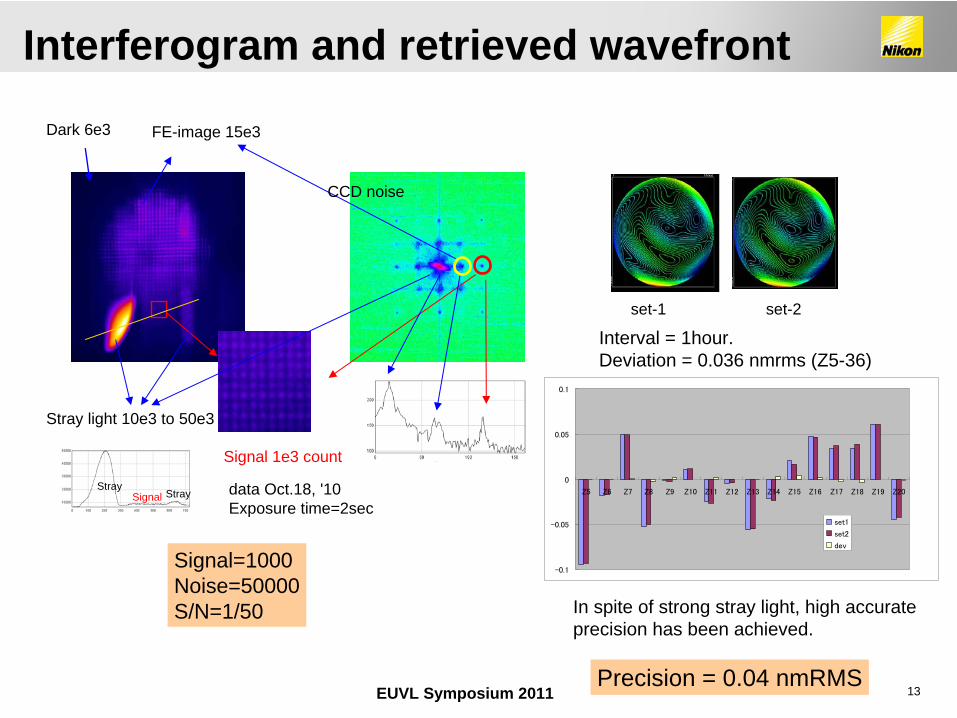
Stray light 10e3 to 50e3
Dark 6e3 FE-image 15e3
Signal 1e3 count
Signal=1000Noise=50000S/N=1/50
SignalStray
Stray data Oct.18, '10 Exposure time=2sec
CCD noise
set-1 set-2
Interval = 1hour.Deviation = 0.036 nmrms (Z5-36)
In spite of strong stray light, high accurateprecision has been achieved.
-0.1
-0.05
0
0.05
0.1
Z5 Z6 Z7 Z8 Z9 Z10 Z11 Z12 Z13 Z14 Z15 Z16 Z17 Z18 Z19 Z20
set1
set2
dev
Precision = 0.04 nmRMS
Interferogram and retrieved wavefront
14EUVL Symposium 2011
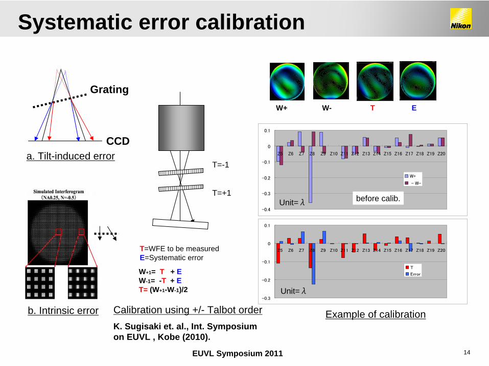
K. Sugisaki et. al., Int. Symposium on EUVL , Kobe (2010).
W+1= T + EW-1= -T + ET= (W+1-W-1)/2
T=-1
T=+1
T=WFE to be measured E=Systematic error
b. Intrinsic error
a. Tilt-induced error
W+ W- T E
Calibration using +/- Talbot order
-0.4
-0.3
-0.2
-0.1
0
0.1
Z5 Z6 Z7 Z8 Z9 Z10 Z11 Z12 Z13 Z14 Z15 Z16 Z17 Z18 Z19 Z20
W+
- W-
-0.3
-0.2
-0.1
0
0.1
Z5 Z6 Z7 Z8 Z9 Z10 Z11 Z12 Z13 Z14 Z15 Z16 Z17 Z18 Z19 Z20
T
Error
before calib.Unit=λ
Example of calibration
Unit=λ
Systematic error calibration
Grating
CCD
15EUVL Symposium 2011
BackgroundPrinciple of the MetrologyMISTI@UECMISTI@SeleteAberration controllabilityAberration adjustment and verificationSummary
Outline
16EUVL Symposium 2011
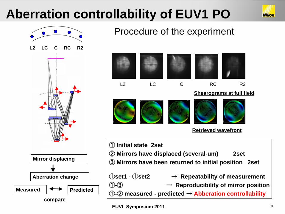
Shearograms at full field
Retrieved wavefront
L2 LC C RC R2
① Initial state 2set② Mirrors have displaced (several-um) 2set ③ Mirrors have been returned to initial position 2set
①set1 - ①set2 →
Repeatability of measurement①-③ → Reproducibility of mirror position①-② measured - predicted → Abberation controllability
L2 LC C RC R2
Mirror displacing
Aberration change
Measured Predicted
compare
Aberration controllability of EUV1 POProcedure of the experiment
17EUVL Symposium 2011
0
0.02
0.04
0.06
0.08
0.1
L2 LC C2 RC R2
Field position
Err
or
(nm
RM
S)
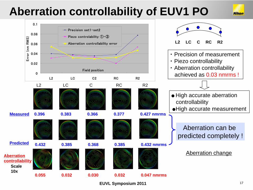
Precision set1-set2
Piezo controlability ①-③
Aberration controllability error
Aberration change
0.396 0.383 0.366 0.377 0.427 nmrms
0.432 0.385 0.368 0.385 0.432 nmrms
Measured
Predicted
0.055 0.032 0.030 0.032 0.047 nmrms
Aberration controllability
Scale 10x
L2 LC C RC R2
・
Precision of measurement ・
Piezo controllability・
Aberration controllabilityachieved as 0.03 nmrms !
●
High accurate aberration controllability
●
High accurate measurement
Aberration can be predicted completely !
L2 LC C RC R2
Aberration controllability of EUV1 PO
18EUVL Symposium 2011
BackgroundPrinciple of the MetrologyMISTI@UECMISTI@SeleteAberration controllabilityAberration adjustment and verificationSummary
Outline
19EUVL Symposium 2011
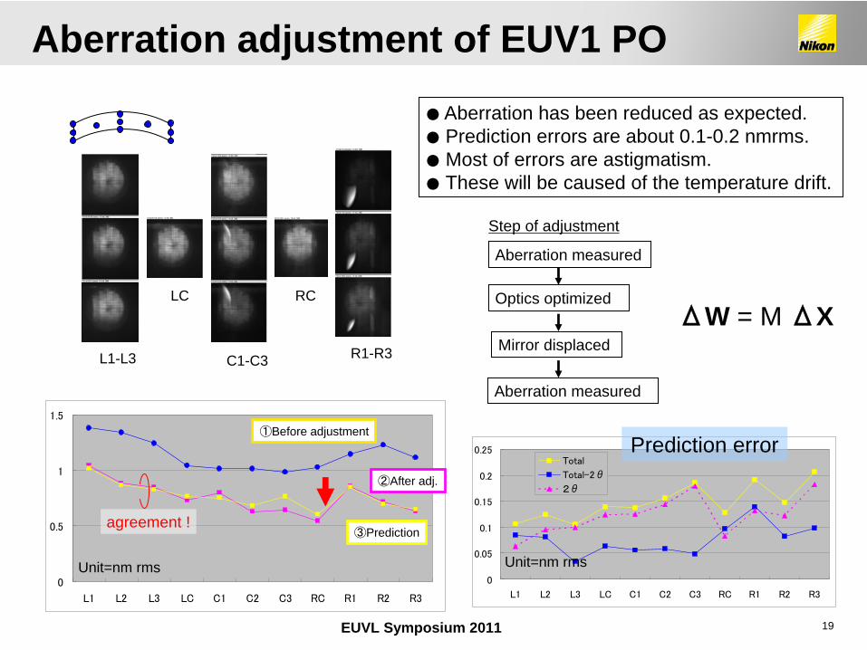
LC RC
● Aberration has been reduced as expected.●
Prediction errors are about 0.1-0.2 nmrms.●
Most of errors are astigmatism.●
These will be caused of the temperature drift.
Aberration measured
Optics optimized
Mirror displaced
Aberration measured
Step of adjustment
ΔW = M ΔX
0
0.5
1
1.5
L1 L2 L3 LC C1 C2 C3 RC R1 R2 R3
0
0.05
0.1
0.15
0.2
0.25
L1 L2 L3 LC C1 C2 C3 RC R1 R2 R3
Total
Total-2θ
2θ
L1-L3 C1-C3 R1-R3
agreement !
①Before adjustment
②After adj.
③Prediction
Unit=nm rms Unit=nm rms
Prediction error
Aberration adjustment of EUV1 PO
20EUVL Symposium 2011
Wav
efro
nt e
rror
(nm
rm
s)
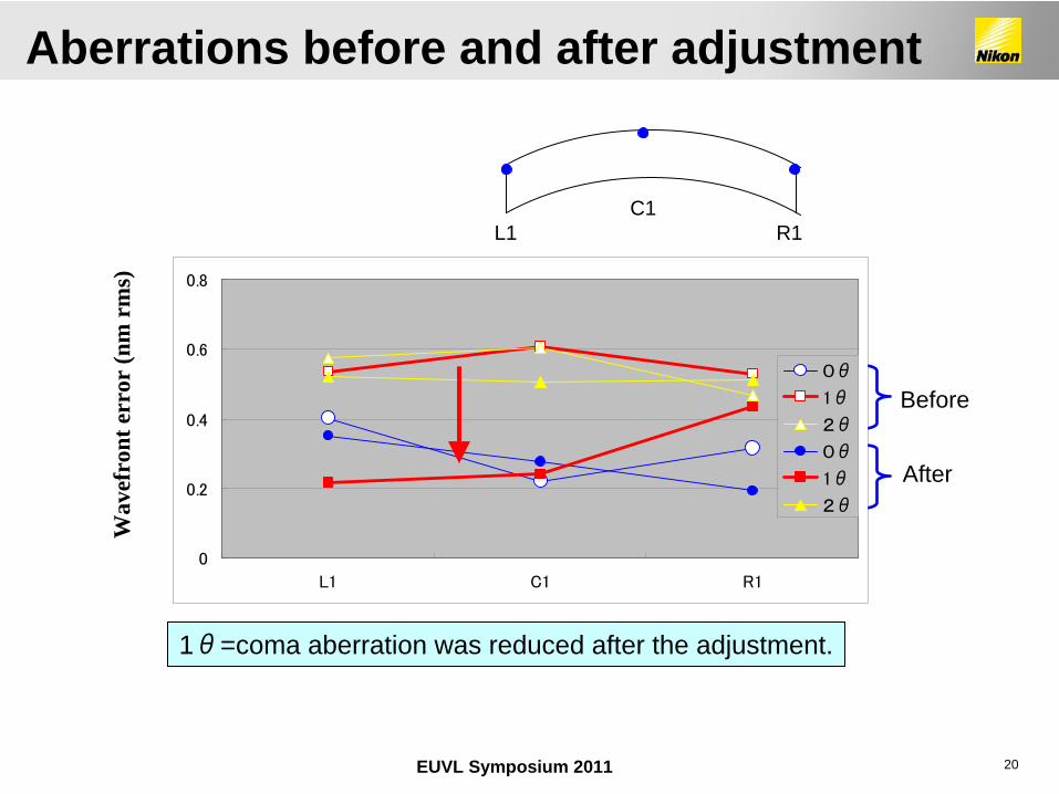
1θ=coma aberration was reduced after the adjustment.
C1L1 R1
Before
After
0
0.2
0.4
0.6
0.8
L1 C1 R1
0θ
1θ
2θ
0θ
1θ
2θ
Aberrations before and after adjustment
21EUVL Symposium 2011
CD
(nm
)
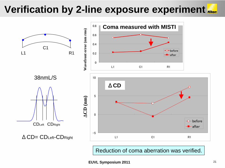
ΔCD= CDLeft-CDRight
38nmL/S
Reduction of coma aberration was verified.
-5
0
5
10
L1 C1 R1
before
after
C1L1 R1
CDLeft CDRight
0
0.2
0.4
0.6
0.8
L1 C1 R1
before
after
Coma measured with MISTI
ΔCD W
avef
ront
err
or (n
m r
ms)
Verification by 2-line exposure experiment
22EUVL Symposium 2011
On-machine measurement system, MISTI, have been developed and installed to the full-field EUVL exposure tool, EUV1. A lack of source power has been solved by using pinhole clusters and 106 times of power increase has been achieved.
We intentionally produced aberration change by displacing the mirrors of EUV1 projection optics and compared the measured and the predicted aberration. As a result, aberration controllability of 0.03nm in RMS was confirmed.
We have tried to adjust aberration of projection optics on EUV1 using MISTI and reduction of coma aberration was confirmed.
Completeness of EUV1 projection optics has been proved.
Summary
23EUVL Symposium 2011
We would like to thank to
S.Ishiyama, S.Ogata, T.Miyachi, A.Hayakawa K.Sugisaki and other staffs of Nikon.
Selete for time consuming of our experiment.
Staffs of Canon Inc. and Prof. M.Takeda, UEC for exploiting the useful results of the joint study.
Acknowledgment