TECHNOLOGICAL AND ECONOMIC EVALUATION OF DISTRICT COOLING WITH
© 2016 IEEE. Personal use of this material is permitted. Permission from IEEE must be obtained for all other uses, in any current or future media, including reprinting/republishing this material for advertising or promotional purposes, creating new collective works, for resale or redistribution to servers or lists, or reuse of any copyrighted component of this work in other works.
Evaluation of a new data center air-cooling architecture; the down-flow plenum
Daniel Hackenberg
Center for Information Services and High Performance Computing Technische Universität Dresden
01062 Dresden, Saxony, Germany Email: [email protected]
Michael K. Patterson Technical Computing Group Systems Architecture and Pathfinding
Intel Corporation Dupont, Washington, USA
Email: [email protected]
ABSTRACT The rate of innovation in IT system design and especially
in High Performance Computing continues to be very high. To keep pace TU Dresden has constructed its new data center using the Plenum concept. The traditional raised floor was substituted by a full building story, creating a highly flexible space to transport power, water, and air. A strict hot-aisle air separation is used and the computer room air-handling (CRAH) units in downflow configuration are positioned directly beneath the hot aisles. This unique arrangement necessitates an unconventional downward flow of hot air from the enclosed hot aisle. Extensive testing has been performed in a cluster of 24 racks (12 per side) equipped with (3+1)x100 kW CRAH unit cooling capacity and 60 test fixtures (air heaters) with 5-15 kW heating power each. Our analysis demonstrates the extremely high efficiency of this air cooling concept even in high-density configurations, up to at least 30 kW per rack. This efficiency is mostly due to the very short airflow paths and wide open cross-sections. We also showcase that no malicious thermal stratification occurs in our hot air downflow configuration. A detailed analysis of the CRAH controls for temperature (through cooling water flow modulation) and airflow (fan speed) highlights the challenges of such control systems in enclosed hot aisle configurations at high power density and short feedback loops. The analysis also considers dynamically changing load patterns including very low partial load scenarios and aspects of operational reliability.
KEY WORDS: data center, air cooling, raised floor, plenum, containment
INTRODUCTION AND MOTIVATION Data Centers are a critical component of the IT industry,
housing the majority of servers that are the workhorses of the HPC, Cloud, and Enterprise IT segments. There have been, and continue to be, such impressive technology gains in the IT hardware that typical data center architectures have been left in the past. New data center designs and concepts are required to support the ability for the IT owner to install, ramp, and operate larger and more capable hardware installations. The commoditization of the IT side has demanded an increased engineering focus on the data center side of the equation.
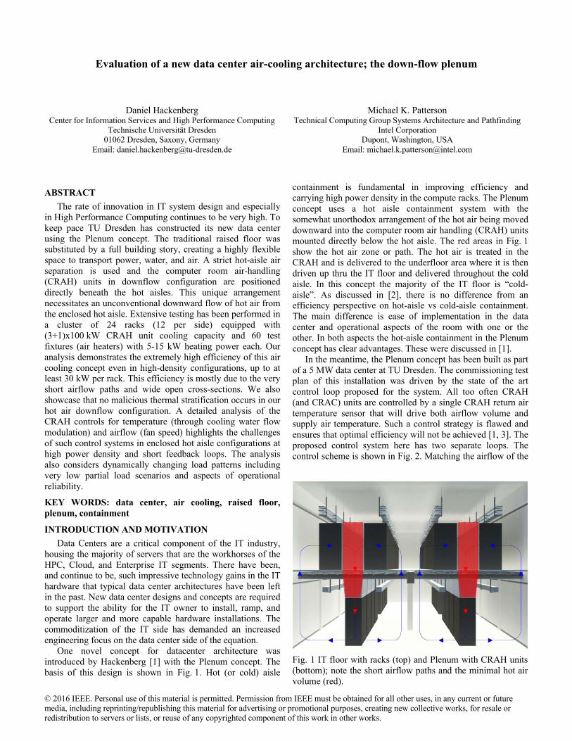
One novel concept for datacenter architecture was introduced by Hackenberg [1] with the Plenum concept. The basis of this design is shown in Fig. 1. Hot (or cold) aisle
containment is fundamental in improving efficiency and carrying high power density in the compute racks. The Plenum concept uses a hot aisle containment system with the somewhat unorthodox arrangement of the hot air being moved downward into the computer room air handling (CRAH) units mounted directly below the hot aisle. The red areas in Fig. 1 show the hot air zone or path. The hot air is treated in the CRAH and is delivered to the underfloor area where it is then driven up thru the IT floor and delivered throughout the cold aisle. In this concept the majority of the IT floor is “cold-aisle”. As discussed in [2], there is no difference from an efficiency perspective on hot-aisle vs cold-aisle containment. The main difference is ease of implementation in the data center and operational aspects of the room with one or the other. In both aspects the hot-aisle containment in the Plenum concept has clear advantages. These were discussed in [1].
In the meantime, the Plenum concept has been built as part of a 5 MW data center at TU Dresden. The commissioning test plan of this installation was driven by the state of the art control loop proposed for the system. All too often CRAH (and CRAC) units are controlled by a single CRAH return air temperature sensor that will drive both airflow volume and supply air temperature. Such a control strategy is flawed and ensures that optimal efficiency will not be achieved [1, 3]. The proposed control system here has two separate loops. The control scheme is shown in Fig. 2. Matching the airflow of the
Fig. 1 IT floor with racks (top) and Plenum with CRAH units (bottom); note the short airflow paths and the minimal hot air volume (red).
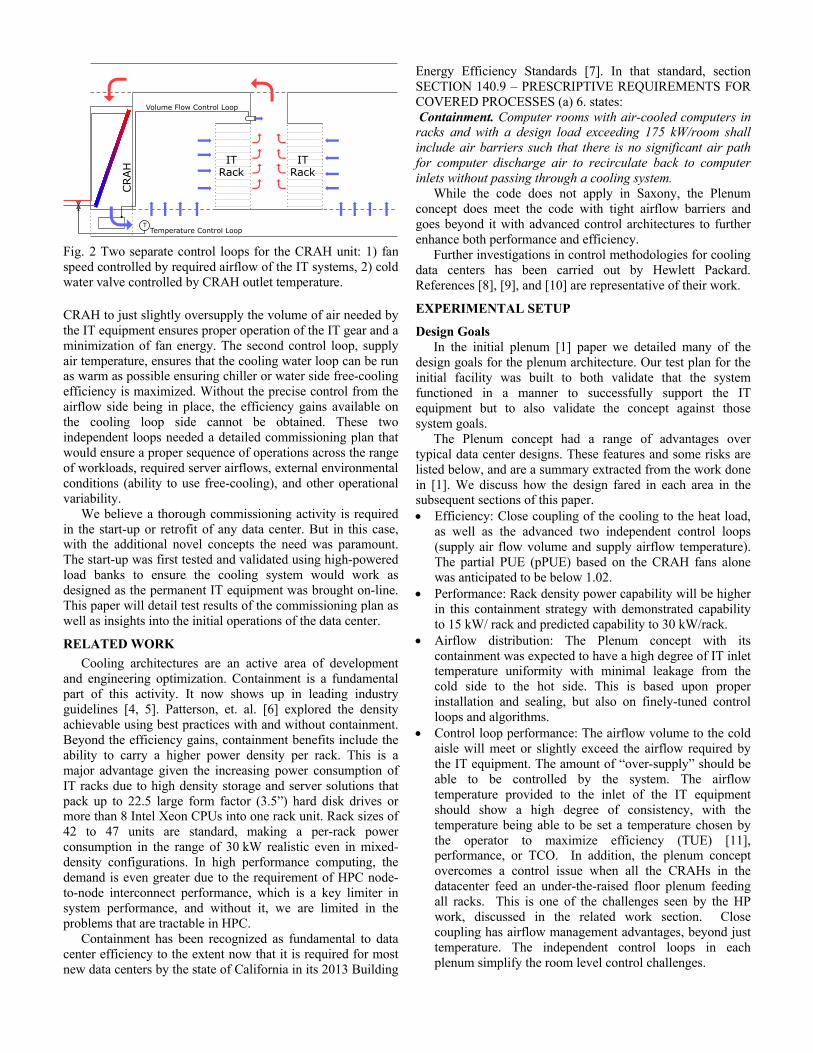
CRAH to just slightly oversupply the volume of air needed by the IT equipment ensures proper operation of the IT gear and a minimization of fan energy. The second control loop, supply air temperature, ensures that the cooling water loop can be run as warm as possible ensuring chiller or water side free-cooling efficiency is maximized. Without the precise control from the airflow side being in place, the efficiency gains available on the cooling loop side cannot be obtained. These two independent loops needed a detailed commissioning plan that would ensure a proper sequence of operations across the range of workloads, required server airflows, external environmental conditions (ability to use free-cooling), and other operational variability.
We believe a thorough commissioning activity is required in the start-up or retrofit of any data center. But in this case, with the additional novel concepts the need was paramount. The start-up was first tested and validated using high-powered load banks to ensure the cooling system would work as designed as the permanent IT equipment was brought on-line. This paper will detail test results of the commissioning plan as well as insights into the initial operations of the data center.
RELATED WORK Cooling architectures are an active area of development
and engineering optimization. Containment is a fundamental part of this activity. It now shows up in leading industry guidelines [4, 5]. Patterson, et. al. [6] explored the density achievable using best practices with and without containment. Beyond the efficiency gains, containment benefits include the ability to carry a higher power density per rack. This is a major advantage given the increasing power consumption of IT racks due to high density storage and server solutions that pack up to 22.5 large form factor (3.5”) hard disk drives or more than 8 Intel Xeon CPUs into one rack unit. Rack sizes of 42 to 47 units are standard, making a per-rack power consumption in the range of 30 kW realistic even in mixed-density configurations. In high performance computing, the demand is even greater due to the requirement of HPC node-to-node interconnect performance, which is a key limiter in system performance, and without it, we are limited in the problems that are tractable in HPC.
Containment has been recognized as fundamental to data center efficiency to the extent now that it is required for most new data centers by the state of California in its 2013 Building
Energy Efficiency Standards [7]. In that standard, section SECTION 140.9 – PRESCRIPTIVE REQUIREMENTS FOR COVERED PROCESSES (a) 6. states: Containment. Computer rooms with air-cooled computers in racks and with a design load exceeding 175 kW/room shall include air barriers such that there is no significant air path for computer discharge air to recirculate back to computer inlets without passing through a cooling system.
While the code does not apply in Saxony, the Plenum concept does meet the code with tight airflow barriers and goes beyond it with advanced control architectures to further enhance both performance and efficiency.
Further investigations in control methodologies for cooling data centers has been carried out by Hewlett Packard. References [8], [9], and [10] are representative of their work.
EXPERIMENTAL SETUP
Design Goals In the initial plenum [1] paper we detailed many of the
design goals for the plenum architecture. Our test plan for the initial facility was built to both validate that the system functioned in a manner to successfully support the IT equipment but to also validate the concept against those system goals.
The Plenum concept had a range of advantages over typical data center designs. These features and some risks are listed below, and are a summary extracted from the work done in [1]. We discuss how the design fared in each area in the subsequent sections of this paper. • Efficiency: Close coupling of the cooling to the heat load,
as well as the advanced two independent control loops (supply air flow volume and supply airflow temperature). The partial PUE (pPUE) based on the CRAH fans alone was anticipated to be below 1.02.
• Performance: Rack density power capability will be higher in this containment strategy with demonstrated capability to 15 kW/ rack and predicted capability to 30 kW/rack.
• Airflow distribution: The Plenum concept with its containment was expected to have a high degree of IT inlet temperature uniformity with minimal leakage from the cold side to the hot side. This is based upon proper installation and sealing, but also on finely-tuned control loops and algorithms.
• Control loop performance: The airflow volume to the cold aisle will meet or slightly exceed the airflow required by the IT equipment. The amount of “over-supply” should be able to be controlled by the system. The airflow temperature provided to the inlet of the IT equipment should show a high degree of consistency, with the temperature being able to be set a temperature chosen by the operator to maximize efficiency (TUE) [11], performance, or TCO. In addition, the plenum concept overcomes a control issue when all the CRAHs in the datacenter feed an under-the-raised floor plenum feeding all racks. This is one of the challenges seen by the HP work, discussed in the related work section. Close coupling has airflow management advantages, beyond just temperature. The independent control loops in each plenum simplify the room level control challenges.
IT Rack
IT Rack
T
Volume Flow Control Loop
Temperature Control Loop
CRAH
Fig. 2 Two separate control loops for the CRAH unit: 1) fan speed controlled by required airflow of the IT systems, 2) cold water valve controlled by CRAH outlet temperature.
• Serviceability: The large open cold-aisle access to the IT racks on the IT floor and the open spaces with infrastructure support equipment (power and cooling) in the lower level would lead to better serviceability of respectively owned equipment across the various sections of the organization.
• Controlled access: The location of IT equipment separate from infrastructure equipment will minimize access ways and extra controls needed to ensure only appropriate personnel have access to the different zones.
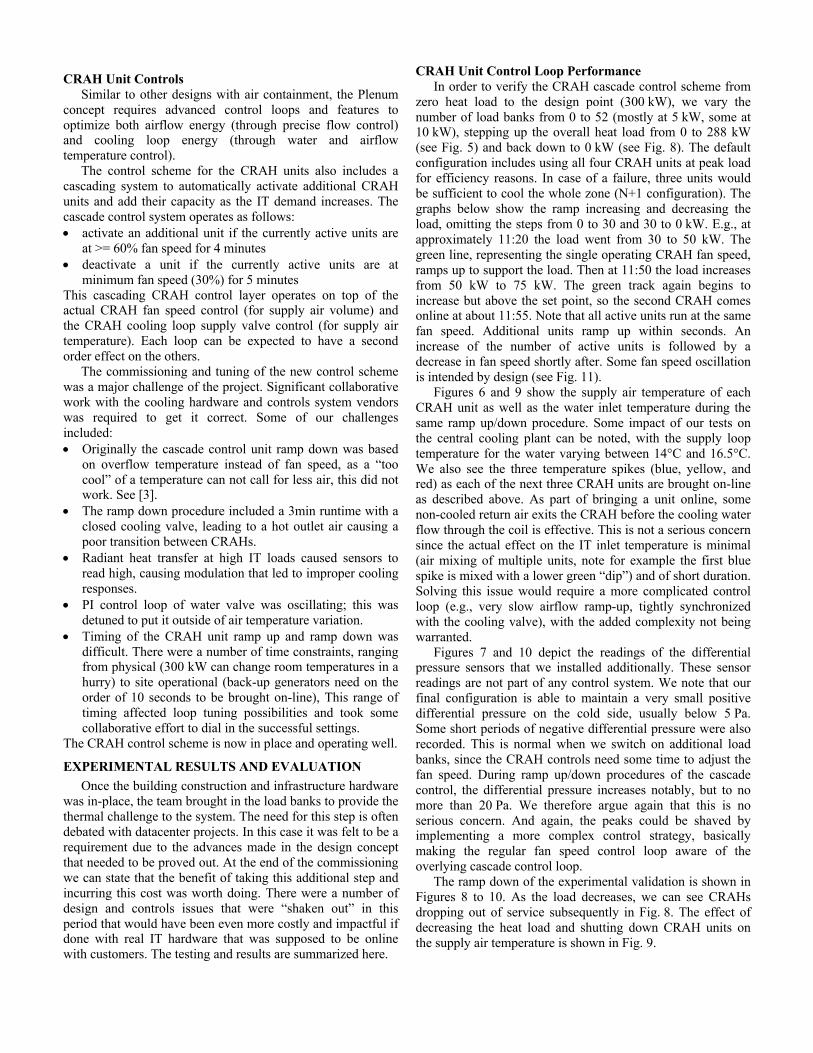
Test Room The test room mimicked an operational zone as defined for
the populated data center. Fig. 3 is representative of this zone. The central corridor shows the four CRAH units in the hot aisle containment. These are located below the grated floor tiles in the hot aisle. The area between the racks is enclosed with a ceiling and doors at each end. This creates the containment. The CRAH units cool the return air and distribute it under the IT floor where it is distributed up into the larger cold aisle. This cold aisle area is depicted by the blue tiles in Fig. 3.
The CRAH units used for the test are the same as the full installation. They are Emerson PH081EL, with extended height and a downflow configuration with two EC fans below the cooling unit. These exhaust freely into the plenum. There is filtration to filter class F5 on each CRAH.
It should be noted that there is no additional functionality in the CRAHs such as heating or humidity control. ASHRAE [12] has extended the range of allowable humidity in IT spaces. Individual humidification units in each CRAH were considered overkill for this project. They generally add cost and complexity, while often contributing to poor efficiency and excess water use. Data center lore is replete with stories of one CRAH humidifying with its neighbor dehumidifying. For this project we took advantage of the wider ASHRAE ranges and are controlling humidity at the room level (vs. at the CRAH level) with associated cost reductions and controls simplification benefits. The outside air supply of the test room was deactivated, the absolute humidity varied between 7.5 and 8.5 g/m3, and no condensation occurred at any time.
In the provisioned data center the rack positions of Fig. 4 will hold IT equipment. This will typically be enterprise class
equipment, nominally at 10-15 kW per rack. For our commissioning test we used 60 Rotek HF-15-400-BG load banks, each with fixed airflow rating of 1292 m3/h and an adjustable capacity of 5/10/15 kW, of which we mostly ran the 5 kW configuration (4.8 kW according to our power consumption measurements) Three load banks were installed per rack in 20 of the 24 racks. We varied the load by switching on or off load banks and made sure that inactive units were covered with blanks to minimize unwanted airflow. For our peak load tests we used 10-30 kW per rack using two or three load banks, resulting in a temperature rise of 11.5-34.5°K. The nominal airflow at peak load using 60 units was 77500 m3/h, or 1211 m3/h per tile based on 4x16=64 perforated tiles on the cold side. At 38% open area, the pressure drop of the floor tiles at peak load is below 10 Pa.
Sensors and Data Collection The monitoring and instrumentation was accomplished
with industry standard tools as well as some developed at TU-Dresden. Power measurements for the load banks were collected from two Janitza UMG96RM-E power analyzers. The CRAH unit power consumption could not be continuously measured, but was confirmed to be within 7% of the data sheet value for one load point (69% fan speed). Data regarding valve openings, temperatures, and fan speeds were recorded directly from the four CRAH units. To provide additional insight into the performance of the overflow air temperature based airflow control system, we used two FISCHER DE46 differential pressure sensors with a measuring range of -20/+80 Pa. These were installed between hot and cold aisle at the top of the containment on both rack rows. All data was collected using the Dataheap tool [13] and the BACnet building automation network at 0.1 to 1 samples/s.
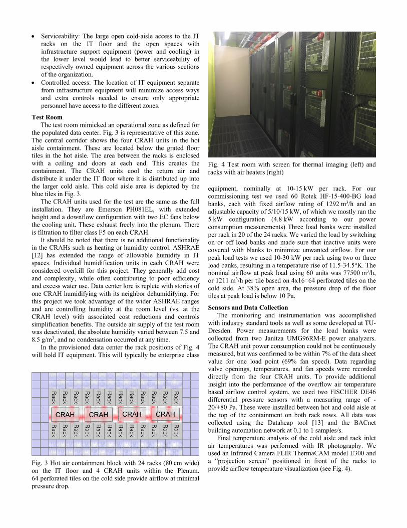
Final temperature analysis of the cold aisle and rack inlet air temperatures was performed with IR photography. We used an Infrared Camera FLIR ThermaCAM model E300 and a “projection screen” positioned in front of the racks to provide airflow temperature visualization (see Fig. 4).
Fig. 3 Hot air containment block with 24 racks (80 cm wide) on the IT floor and 4 CRAH units within the Plenum. 64 perforated tiles on the cold side provide airflow at minimal pressure drop.
Fig. 4 Test room with screen for thermal imaging (left) and racks with air heaters (right)
CRAH Unit Controls Similar to other designs with air containment, the Plenum
concept requires advanced control loops and features to optimize both airflow energy (through precise flow control) and cooling loop energy (through water and airflow temperature control).
The control scheme for the CRAH units also includes a cascading system to automatically activate additional CRAH units and add their capacity as the IT demand increases. The cascade control system operates as follows: • activate an additional unit if the currently active units are
at >= 60% fan speed for 4 minutes • deactivate a unit if the currently active units are at
minimum fan speed (30%) for 5 minutes This cascading CRAH control layer operates on top of the actual CRAH fan speed control (for supply air volume) and the CRAH cooling loop supply valve control (for supply air temperature). Each loop can be expected to have a second order effect on the others.
The commissioning and tuning of the new control scheme was a major challenge of the project. Significant collaborative work with the cooling hardware and controls system vendors was required to get it correct. Some of our challenges included: • Originally the cascade control unit ramp down was based
on overflow temperature instead of fan speed, as a “too cool” of a temperature can not call for less air, this did not work. See [3].
• The ramp down procedure included a 3min runtime with a closed cooling valve, leading to a hot outlet air causing a poor transition between CRAHs.
• Radiant heat transfer at high IT loads caused sensors to read high, causing modulation that led to improper cooling responses.
• PI control loop of water valve was oscillating; this was detuned to put it outside of air temperature variation.
• Timing of the CRAH unit ramp up and ramp down was difficult. There were a number of time constraints, ranging from physical (300 kW can change room temperatures in a hurry) to site operational (back-up generators need on the order of 10 seconds to be brought on-line), This range of timing affected loop tuning possibilities and took some collaborative effort to dial in the successful settings.
The CRAH control scheme is now in place and operating well.
EXPERIMENTAL RESULTS AND EVALUATION Once the building construction and infrastructure hardware
was in-place, the team brought in the load banks to provide the thermal challenge to the system. The need for this step is often debated with datacenter projects. In this case it was felt to be a requirement due to the advances made in the design concept that needed to be proved out. At the end of the commissioning we can state that the benefit of taking this additional step and incurring this cost was worth doing. There were a number of design and controls issues that were “shaken out” in this period that would have been even more costly and impactful if done with real IT hardware that was supposed to be online with customers. The testing and results are summarized here.
CRAH Unit Control Loop Performance In order to verify the CRAH cascade control scheme from
zero heat load to the design point (300 kW), we vary the number of load banks from 0 to 52 (mostly at 5 kW, some at 10 kW), stepping up the overall heat load from 0 to 288 kW (see Fig. 5) and back down to 0 kW (see Fig. 8). The default configuration includes using all four CRAH units at peak load for efficiency reasons. In case of a failure, three units would be sufficient to cool the whole zone (N+1 configuration). The graphs below show the ramp increasing and decreasing the load, omitting the steps from 0 to 30 and 30 to 0 kW. E.g., at approximately 11:20 the load went from 30 to 50 kW. The green line, representing the single operating CRAH fan speed, ramps up to support the load. Then at 11:50 the load increases from 50 kW to 75 kW. The green track again begins to increase but above the set point, so the second CRAH comes online at about 11:55. Note that all active units run at the same fan speed. Additional units ramp up within seconds. An increase of the number of active units is followed by a decrease in fan speed shortly after. Some fan speed oscillation is intended by design (see Fig. 11).
Figures 6 and 9 show the supply air temperature of each CRAH unit as well as the water inlet temperature during the same ramp up/down procedure. Some impact of our tests on the central cooling plant can be noted, with the supply loop temperature for the water varying between 14°C and 16.5°C. We also see the three temperature spikes (blue, yellow, and red) as each of the next three CRAH units are brought on-line as described above. As part of bringing a unit online, some non-cooled return air exits the CRAH before the cooling water flow through the coil is effective. This is not a serious concern since the actual effect on the IT inlet temperature is minimal (air mixing of multiple units, note for example the first blue spike is mixed with a lower green “dip”) and of short duration. Solving this issue would require a more complicated control loop (e.g., very slow airflow ramp-up, tightly synchronized with the cooling valve), with the added complexity not being warranted.
Figures 7 and 10 depict the readings of the differential pressure sensors that we installed additionally. These sensor readings are not part of any control system. We note that our final configuration is able to maintain a very small positive differential pressure on the cold side, usually below 5 Pa. Some short periods of negative differential pressure were also recorded. This is normal when we switch on additional load banks, since the CRAH controls need some time to adjust the fan speed. During ramp up/down procedures of the cascade control, the differential pressure increases notably, but to no more than 20 Pa. We therefore argue again that this is no serious concern. And again, the peaks could be shaved by implementing a more complex control strategy, basically making the regular fan speed control loop aware of the overlying cascade control loop.
The ramp down of the experimental validation is shown in Figures 8 to 10. As the load decreases, we can see CRAHs dropping out of service subsequently in Fig. 8. The effect of decreasing the heat load and shutting down CRAH units on the supply air temperature is shown in Fig. 9.
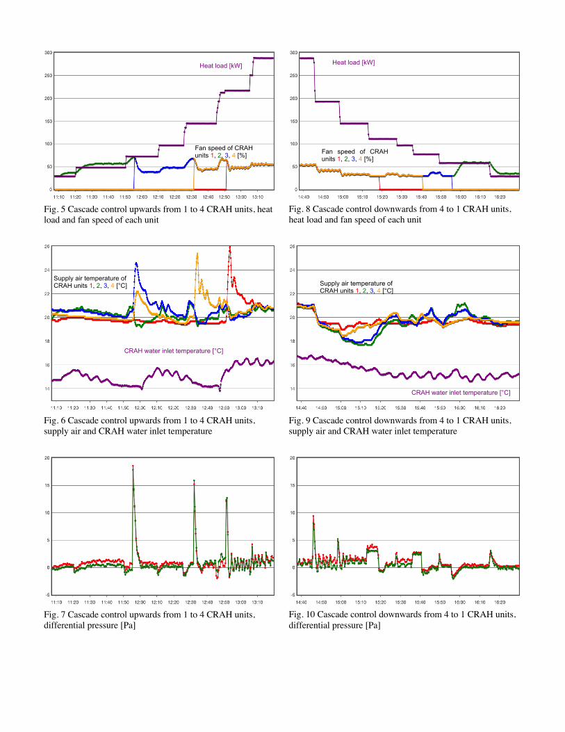
Fig. 5 Cascade control upwards from 1 to 4 CRAH units, heat load and fan speed of each unit
Fig. 6 Cascade control upwards from 1 to 4 CRAH units, supply air and CRAH water inlet temperature
Fig. 7 Cascade control upwards from 1 to 4 CRAH units, differential pressure [Pa]
Fig. 8 Cascade control downwards from 4 to 1 CRAH units, heat load and fan speed of each unit
Fig. 9 Cascade control downwards from 4 to 1 CRAH units, supply air and CRAH water inlet temperature
Fig. 10 Cascade control downwards from 4 to 1 CRAH units, differential pressure [Pa]
Fan speed of CRAH units 1, 2, 3, 4 [%]
Supply air temperature of CRAH units 1, 2, 3, 4 [°C]
Heat load [kW]
CRAH water inlet temperature [°C]
CRAH water inlet temperature [°C]
Heat load [kW]
Fan speed of CRAH units 1, 2, 3, 4 [%]
Supply air temperature of CRAH units 1, 2, 3, 4 [°C]
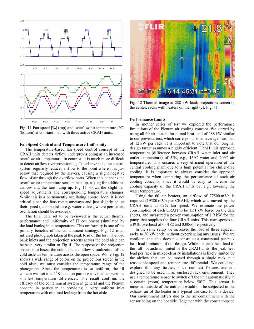
Fan Speed Control and Temperature Uniformity The temperature-based fan speed control concept of the
CRAH units detects airflow underprovisioning as an increased overflow air temperature. In contrast, it is much more difficult to detect airflow overprovisioning. To achieve this, the control system regularly reduces airflow to the point where it is just below that required by the servers, causing a slight negative flow of air through the overflow ports. When this happens the overflow air temperature sensors heat up, asking for additional airflow and the fans ramp up. Fig. 11 shows the slight fan speed adjustments and corresponding temperature changes. While this is a permanently oscillating control loop, it is not critical since the fans rotate anyways and just slightly adjust their speed (as opposed to e.g. water valves, where permanent oscillation should be avoided).
The final data set to be reviewed is the actual thermal performance and uniformity of IT equipment (simulated by the load banks) inlet temperature. This uniformity is one of the primary benefits of the containment strategy. Fig. 12 is an infrared photograph taken at the peak load of the test. The load bank inlets and the projection screens across the cold aisle can be seen, very similar to Fig. 4. The purpose of the projection screen is to bisect the cold aisle and allow visualization of the cold aisle air temperature across the open space. While Fig. 12 shows a wide range of colors on the projections screen in the cold aisle, we must consider the temperature range of the photograph. Since the temperature is so uniform, the IR camera was set to a 2°K band on purpose to visualize even the smallest temperature differences. The result confirms the efficacy of the containment system in general and the Plenum concept in particular at providing a very uniform inlet temperature with minimal leakage from the hot aisle.
Performance Limits In another series of test we explored the performance
limitations of the Plenum air cooling concept. We started by using all 60 air heaters for a total heat load of 288 kW similar to our previous test, which corresponds to an average heat load of 12 kW per rack. It is important to note that our original design target assumes a highly efficient CRAH unit approach temperature (difference between CRAH water inlet and air outlet temperature) of 5°K, e.g., 15°C water and 20°C air temperature. This ensures a very efficient operation of the central cooling plant due to a high potential for chiller-free cooling. It is important to always consider the approach temperature when comparing the performance of such air cooling concepts, since it would be easy to increase the cooling capacity of the CRAH units by, e.g., lowering the water temperature.
Using the 60 air heaters, an airflow of 77500 m3/h is required (19380 m3/h per CRAH), which was moved by the CRAH units at 62% fan speed. We estimate the power consumption of each CRAH to be 1.31 kW based on the data sheets, and measured a power consumption of 1.9 kW for the pump that supplies the four CRAH units. This corresponds to a PUE overhead of 0.0182 and 0.0066, respectively.
In the same setup we increased the load of three adjacent racks to 30 kW each, without experiencing any issues. We are confident that this does not constitute a conceptual per-rack heat load limitation of our design. While the peak heat load of the full hot aisle is limited by the CRAH units, the peak heat load per rack in mixed-density installations is likely limited by the airflow that can be moved through a single rack at a reasonable speed and temperature differential. We could not explore this any further, since our test fixtures are not designed to be used in an enclosed rack environment. They use a temperature sensor to switch off the unit automatically at a certain (room) temperature below 50°C. This sensor is mounted outside of the unit and would not be subjected to the exhaust air of the heater in a typical use case for this device. Our environment differs due to the air containment with the sensor being on the hot side. Together with the constant-speed
Fig. 12 Thermal image at 288 kW load; projections screen in the center, racks with heaters on the right (cf. Fig. 4)
Fig. 11 Fan speed [%] (top) and overflow air temperature [°C] (bottom) at constant load with three active CRAH units.

fans, this prevented us from increasing the load for some racks beyond 30 kW, since the heaters reach the peak temperature at this sensor and automatically switch off.
Still at 288 kW heat load and 77500 m3/h airflow, we switched off one CRAH unit to verify that the system works without the n+1 unit. The three remaining CRAH units were able to perform flawlessly, mostly maintaining the regular 5°K approach temperature at (close to) 100% valve opening and a differential pressure of 0.5-3 Pa (slight overprovisioning) at 84% fan speed.
In our final series of experiments we intended to determine the limits of the Plenum concept beyond the original design point that was relevant for the installation at TU Dresden. When the n+1 redundancy CRAH unit fails at very high load, it could be reasonable to accept a slightly increased approach temperature by either automatically reducing the cold water temperature of the cooling plant or accepting an increased CRAH supply air (IT inlet) temperature. At constant airflow, we increased the approach temperature to 9°K (16°C water inlet and 25°C supply air temperature) and the heat load to 480 kW, corresponding to an average of 20 kW per rack (or 24 kW when counting only the 20 racks that were populated with air heaters). Three active CRAH units were able to support this load at 60-90% valve opening. Only the air heater thermostats prevented us from increasing the load even more.
After switching on the fourth unit, the CRAHs returned to 63% fan speed (estimated power consumption of 1.39 kW per unit) for a differential pressure between cold and hot aisle of 0-1 Pa. Valve openings were 45-50% at a pump power consumption of 2 kW. Given the 480 kW IT test load, the PUE overhead of the CRAH units and pump at 9°K approach temperature were 0.0116 and 0.0042, respectively.
OPERATIONAL EXPERIENCE Since the initial testing and commissioning has been
completed, multiple rooms with IT equipment have been installed and brought online. No issues associated with the cooling architecture occurred. Of particular note, with regard to our initial design goals, we can make the following observations: • Efficiency: At our peak load point using four CRAH units,
their power consumption hast been at ~ 1 kW per unit, resulting in a pPUE of less than 1.015.
• Performance: The data center is currently operational and successfully supporting air-cooled racks ranging from 1 to 15 kW/rack.
• Airflow distribution: No adverse impacts from hot air downflow have been observed, no stratification can be measured. Temperature uniformity at the IT equipment inlet has been measured by IR camera and is generally below 1°K. Leakage has been minimized with application of appropriate best known methods. No cold aisle variability has been noted. There have been no locations that suffered from a lack of cold aisle air availability.
• Control loop performance: The CRAH controls integration was our major challenge as discussed above. We observed that due to the very high power densities and short airflow paths, the control systems need to be configured with much attention to detail. In the final test run, the control system
met our specification exceptionally well, as confirmed by the DP sensors across the containment and our IR camera observations. At peak power densities, a UPS-based power feed to the CRAH control system or even the whole CRAH unit would be advisable. Given the negligible power consumption of the EC fans, this might even be the IT power feed.
• Serviceability has been very good. Extensive work such as controls optimization, trouble shooting, and pipe insulation was ongoing in the infrastructure zone, while hundreds of servers were being installed in the IT zone. The IT team was appreciative of the large cool space during the installation of the IT gear, the infrastructure teams profit extensively from the spacious Plenum area during their work.
• Controlled access: Access issues have not been encountered. The zoning strategy (IT vs. infrastructure) has been successful with no challenges impacting operations, maintenance, or growth.
The thermal and energy performance has been as predicted with no issues. Operations, maintenance, reliability and service access have all been positive as well. We continue to add more IT equipment, paying special attention to purchasing only high density parts for both servers and disk storage in accordance to our original design and the experimental validation.
FURTHER DEVELOPMENT OF THE PLENUM CONCEPT
Original Design and Concept The goals of controlling access and minimizing access
issues, while optimizing both building volume and building area were drivers in the design of the Plenum concept. Fig. 13 shows a typical datacenter and the amount of inter-twined zones inherent in the design.
The Plenum concept greatly simplifies this as seen in Fig. 14. This new concept frees the operations staff from both the IT side and the facilities side of the regular complications of working in each others space found in a typical design data center. This is a synergistic benefit to the concept that was largely driven by efficiency and performance goals.
The TU Dresden data center adds another floor beneath the Plenum for support infrastructure such as transformers, UPS, water-cooled chillers and pumps. It also adds a floor above the IT rooms, which is used mostly for hybrid cooling towers and air-cooled chillers.
Fig. 13 Classic modular data center design: IT space (blue) and supply infrastructure (red, with corridor, CRAH unit rooms and raised floor).

Limitations and Opportunities for an Improved Concept While the concept, in both design and operations has been
a success, it is not without several lessons learned. The separation of A/B feeds for power and cooling is not
ideal; overall power distribution strategies could have been improved.
Projections of high density HPC systems for the future are showing heavier racks. While our design can support heavier racks than currently installed, the static structure cannot be further improved. No additional structural support pillars could be installed in the Plenum due to the floor beneath the Plenum.
Moreover, the existing design layout employs a very solid roof structure to support heavy cooling equipment. This limits opportunities to install direct or indirect outdoor air cooling.
Fig. 15 depicts our proposed extension of the Plenum concept to address the issues mentioned above. To minimize the structural limitations we relocated cooling towers and chillers next to the IT floor versus on the roof, allowing large volumes of outdoor air to be fed into the IT space if needed. It is also much easier to construct a pillar-free IT floor given the more lightweight roof structure. In addition, building the Plenum on the base slab creates opportunities to install structural pillars in the Plenum as needed during the lifetime of the building.
On the downside, the extended concept would require notably greater building area, which would have been unfeasible for the TU Dresden facility, but likely practicable at other sites. The 2D-scalability of the original design in Fig. 14 is discarded, but a natural 1D-scalability (left-to-right in Fig. 15) remains.
SUMMARY In this paper we present an extensive study of the Plenum
concept, a new datacenter design that has been introduced in previous work and since then has been built in a university facility in Germany rated at 5 MW. In our study we find that well-know best practices for air containment are sufficient to ensure safe operation of an air cooling design that does not provide hot air extraction at the IT floor ceiling, but instead sucks IT exhaust air downwards directly from the hot aisle. Our experiments show that best practices for CRAH unit controls are applicable and ensure state-of-the art efficiency, but need to be configured carefully when employed at power densities of >10 kW/rack on average. The conceptual density limitation of this air cooling concept was proven to be beyond 25 kW/rack at a highly efficient operating point that allows for high cooling water temperatures and a pPUE of the CRAH units below 1.015. Operations, maintenance, and service access have proven to be as positive as anticipated during the design phase. We also list some lessons learned and propose and extension of the original design that may further improve the performance and characteristics of the Plenum concept for some use cases.
ACKNOWLEDGEMENTS The authors would like to acknowledge the strong support
of Giuseppe Dalla Mana and Rudolf Pertl of Emerson during the optimization of the CRAH controls. We also acknowledge Jörg Scholich (SIB), Heike Schenk (SIB), Ralf Martin (Architektengemeinschaft Zimmermann) and Jan Boden (Innius DÖ) for their invaluable support regarding the experimental setup and the numerous test runs.
REFERENCES
[1] Daniel Hackenberg. The Plenum concept: Improving scalability, security, and efficiency for data centers, IEEE Intersociety Conference on Thermal and Thermomechanical Phenomena in Electronic Systems (ITherm), 2014, http://dx.doi.org/10.1109/ITHERM.2014.6892408.
[2] T-Systems. DataCenter 2020: hot aisle and cold aisle containment efficiencies reveal no significant differences. DataCenter 2020 White Paper, 2011.
[3] Michael K Patterson, Rainer Weidmann, Markus Leberecht, Manuel Mair, and Richard M Libby. An Investigation Into Cooling System Control Strategies for Data Center Airflow Containment Architectures. ASME Pacific Rim Technical Conference and Exhibition on Packaging and Integration of Electronic and Photonic Systems (InterPACK), 2011, http://dx.doi.org/10.1115/IPACK2011-52090.
[4] DOE. Best Practices Guide for Energy-Efficient Data Center Design. 2011.
[5] Liam Newcombe, Mark Acton, John Booth, Sophia Flucker, Paul Latham, Steve Strutt, and Robert Tozer. Best Practices for the EU Code of Conduct on Data Centres. 2012.
[6] Michael K Patterson, Randall Martin, J Barr von Oehsen, Jim Pepin, Yogendra Joshi, Vaibhav K Arghode, Robin Steinbrecher, and Jeff King. A Field Investigation into the Limits of High-Density Air-Cooling. ASME International
Fig. 14 Data center structure with IT rooms on the upper floor and full-story Plenum on the lower floor.
Fig. 15 Proposed extension of the Plenum concept

Technical Conference and Exhibition on Packaging and Integration of Electronic and Photonic Microsystems (InterPACK), 2013 , http://dx.doi.org/10.1115/IPACK2013-73163.
[7] State of California, Building Energy Efficiency Standards For residential and nonresidential Buildings, 2013, http://www.energy.ca.gov/title24/2013standards/index.html.
[8] Keke Chen, Clifford C Federspiel, David M Auslander, Cullen E Bash, and Chandrakant D Patel. Control Strategies for Plenum Optimization in Raised Floor Data Centers. HP, 2006.
[9] Keke Chen, David M Auslander, Cullen E Bash, and Chandrakant D Patel. Local Temperature Control in Data Center Cooling: Part III, Application. HP, 2006.
[10] Chandrakant D Patel, Cullen E Bash, Christian Belady, Lennart Stahl, and Danny Sullivan. Computational Fluid Dynamics Modeling of High Compute Density Data Centers to Assure System Inlet Air Specifications. The Pacific
Rim/ASME International Electronic Packaging Technical Conference and Exhibition (IPACK), 2001.
[11] Michael K Patterson, Stephen W Poole, Chung-Hsing Hsu, Don Maxwell, William Tschudi, Henry Coles, David J Martinez, and Natalie Bates. TUE, a New Energy-Efficiency Metric Applied at ORNL’s Jaguar. In Lecture Notes in Computer Science. Springer Berlin Heidelberg, 2013, http://dx.doi.org/10.1007/978-3-642-38750-0_28.
[12] ASHRAE. 2011 Thermal Guidelines for Data Processing Environments – Expanded Data Center Classes and Usage Guidance. 2011.
[13] Michael Kluge, Daniel Hackenberg, and Wolfgang E. Nagel. Collecting Distributed Performance Data with Dataheap: Generating and Exploiting a Holistic System View, Procedia Computer Science, Volume 9, 2012, http://dx.doi.org/10.1016/j.procs.2012.04.215.