
Ethernet Ring Protection for Carrier Ethernet Networks
14
1 Ethernet Ring Protection for Carrier Ethernet Networks Jeong-dong Ryoo, ETRI Hao Long and Yang Yang, Huawei Technologies Marc Holness, Nortel Networks Zahir Ahmad and J. Kevin Rhee, Information and Communications University ABSTRACT Ethernet technologies are rapidly becoming a dominant solution for carriers’ networks. Ethernet ring protection switching, defined in ITU-T G.8032 recommendation, provides a means to reliably achieve carrier-class network requirements for Ethernet topologies forming a closed loop. This article outlines an Ethernet ring protection switching mechanism and explains how its automatic protection switching (APS) protocol works. In addition, this article introduces several issues and their potential solutions to enhance Ethernet ring protection for the next phase of standardization. Key words: automatic protection switching, ring protection, Ethernet protection, carrier-class Ethernet INTRODUCTION Ethernet as a carrier-class technology continues to make considerable progresses within carrier networks. In fact, the majority of service providers believe that Ethernet is a mature technology for carrier class deployments. According to a recent market study report [1], over 75% of respondents have a strategy of using Ethernet instead of synchronous digital hierarchy (SDH) or synchronous optical network (SONET) for accessing and collecting customer traffic. Currently, service providers (as well as enterprises) that need rapid restoration and high availability of Ethernet services attainable in ring architectures have been challenged. Although SDH/SONET rings undeniably provide a very high level of protection, synchronous equipment is more expensive than Ethernet-based networking and incurs a heavy bandwidth penalty to achieve its levels of protection. In the recent years, an ITU-T study group SG15/Q9 has developed a technically feasible, economically viable and scalable solution to provide lower cost and the rapid service restoration that delivers
Transcript of Ethernet Ring Protection for Carrier Ethernet Networks

1
Ethernet Ring Protection for Carrier Ethernet
Networks
Jeong-dong Ryoo, ETRI Hao Long and Yang Yang, Huawei Technologies Marc Holness, Nortel Networks Zahir Ahmad and J. Kevin Rhee, Information and Communications University
ABSTRACT Ethernet technologies are rapidly becoming a dominant solution for carriers’ networks. Ethernet ring protection switching, defined in ITU-T G.8032 recommendation, provides a means to reliably achieve carrier-class network requirements for Ethernet topologies forming a closed loop. This article outlines an Ethernet ring protection switching mechanism and explains how its automatic protection switching (APS) protocol works. In addition, this article introduces several issues and their potential solutions to enhance Ethernet ring protection for the next phase of standardization. Key words: automatic protection switching, ring protection, Ethernet protection, carrier-class Ethernet
INTRODUCTION Ethernet as a carrier-class technology continues to make considerable progresses within carrier networks. In fact, the majority of service providers believe that Ethernet is a mature technology for carrier class deployments. According to a recent market study report [1], over 75% of respondents have a strategy of using Ethernet instead of synchronous digital hierarchy (SDH) or synchronous optical network (SONET) for accessing and collecting customer traffic. Currently, service providers (as well as enterprises) that need rapid restoration and high availability of Ethernet services attainable in ring architectures have been challenged. Although SDH/SONET rings undeniably provide a very high level of protection, synchronous equipment is more expensive than Ethernet-based networking and incurs a heavy bandwidth penalty to achieve its levels of protection. In the recent years, an ITU-T study group SG15/Q9 has developed a technically feasible, economically viable and scalable solution to provide lower cost and the rapid service restoration that delivers
2
SDH/SONET-type resilience at Ethernet cost for small-to-medium applications. Recommendation G.8032 on Ethernet ring protection switching is consented [2]. The advent of G.8032 should be welcomed by service providers, since 93% of surveyed service providers use Ethernet collector rings to connect to customer sites [1] and about three quarters have deployed Ethernet overlay networks to deliver Ethernet services. As a competing technology, the resilient packet ring (RPR), defined in IEEE 802.17 [3], has been introduced earlier. RPR is a metropolitan area network (MAN) technology supporting data transfer among stations interconnected in a dual-ring configuration. The values of the RPR include: to provide connectivity across many sites using a shared, packet aware infrastructure, to enable a large reduction in fiber requirements compared with mesh, to provide a 50-ms protection switching time, and to better manage excess information rate (EIR) traffic during traffic congestion/protection scenarios. A new MAC (i.e., 802.17) is developed to achieve its protection switching objectives. It introduces a new MAC header, which is not compatible with ubiquitous Ethernet, and a new set of complex protocols and algorithms (such as topology discovery, fairness algorithm, etc.). This contributes to its complexity and development/deployment expense, and thus lack of economic viability.
Ethernet ring protection (ERP) defined by G.8032 has been developed on a principle of utilizing generic mechanisms inherited from the traditional Ethernet MAC and bridge functions. The objective of fast protection switching is achieved by integrating mature Ethernet operations, administration, and maintenance (OAM) functions and a simple automatic protection switching (APS) protocol for Ethernet ring networks. In addition, since ERP is based on standard Ethernet, it can take advantage of the rapidly increasing Ethernet bandwidth-cost merits with 1GbE, 10GbE, 100GbE, etc., due to its commoditization. In addition, since Ethernet, and thus ERP, is virtually agnostic to all physical/server layer technologies, it can be supported any carrier’s network infrastructure. As a result, it is a more deployable and economically viable solution when compared with RPR. The G.8032 protocol is optimized for ring topologies, and developed as a standardized alternative to replace the spanning tree protocol (STP) for fast transiting the port status without complex computation, provisioning overhead, and excessive information exchange, to thus achieve much faster (i.e., sub-50ms) protection switching. STP is a general (meshed) protocol which is applicable to any kind of networks. However, since it is generic, it does not have any optimization for ring topologies. STP needs much time (i.e., order of seconds) to rebuild topology because it needs information exchange for tree computing. Particularly for a ring, the tree computing is the selection of port to be blocked or opened. The G.8032 protocol is focused to produce optimized process to handle ring protection and should be better performing all variants of STPs, including rapid spanning tree protocol (RSTP) and multiple

3
spanning tree protocol (MSTP), in ring topologies. In summary, G.8032 ERP is developed to meet the following objectives:
� To provide efficient network connectivity. � To provide rapid service restoration (sub-50ms). � To support multiple E-Services (e.g., E-LINE, E-TREE, E-LAN). � To be client and server layer agnostic. That is, G.8032 ERP can be supported over (virtually)
any physical/server layer and can transport (virtually) any Ethernet client. � To utilize existing IEEE 802.1 bridging and IEEE 802.3 MAC hardware. Thus is simply a
software increment on existing Ethernet switching equipment. � To support flexible deployment models. To be deployed in Access, Metro, and Core network
applications. � To leverage Ethernet PHY bandwidth (e.g., 1/10/40/100GbE MAC), cost and time-to-market
curves in support of cost effective and large bandwidth rings. � To be standardized in ITU-T SG15/Q9. � To translate into lower OPEX and CAPEX for the service provider.
ETHERNET RING PROTECTION MECHANISM
RING TOPOLOGY The topology of an Ethernet ring can be a single ring, as described in the current version of G.8032, but is planned to be extended to deal with a multi-ring system. Each ring node has two ring ports per ring and all nodes can be connected in a physically closed loop. Because of the IEEE 802.3 MAC requirement, a logical loop on a physical ring must be avoided. Since a time-to-live (TTL) field is not defined within a native Ethernet frame, looping of traffic being transported over the ring is avoided by blocking traffic at one of the ring ports. Therefore, a physical ring will maintain a logical (non-looping) linear MAC topology with dynamic assignment of end nodes by the ring APS (R-APS) protocol. The G.8032 recommendation does not limits the number of nodes in a ring but recommends it to be in the range between 16 and 255 nodes from an operational perspective. STP is not used on the Ethernet ring ports, and thus suppressed, and is replaced by the ERP protocol. Figure 1 shows the possible variants of Ethernet ring topology. The current G.8032 supports single rings in Figure 1(a) and (b). In the multi-ring cases of Figure 1(c) and (d), rings can be inter-connected via a

4
shared link. In the further development of G.8032, multi-rings and ladder networks consisting of conjoined Ethernet rings will provide the Ethernet ring protection.
(a) (b)
(c) (d)
(a) (b)
(c) (d)
Figure 1: Possible ring topologies; single ring (a), two-single rings with a shared node (b), multi-ring with shared link and nodes (c), and nested multi-ring in a ladder topology (d).
MODELS OF R-APS CHANNEL AND RING NODE
R-APS messages require a virtually isolated and designated transmission channel defined as an R-APS channel for handling and prevention of service channel looping. An R-APS channel is separated from the service traffic channel, but both APS and service traffic channel blockings are placed at the same location. An R-APS channel is configured by use of a separate VLAN assignment, so that the R-APS messages can be handled differently from the service traffic. An R-APS channel blocking is attained by VID filtering by the bridge function defined by IEEE 802.1Q-2005 [4]. Service traffic blocking is also done by VID filtering. Figure 2 presents a model of a ring node and its port blocking. Note that each ring instance only blocks its corresponding VLAN group. A ring node with a blocked port prevents R-APS massages received at one port from being forwarded to the other ring port. However, locally generated R-APS messages by an ERP control process can be inserted to both ring ports. The ERP control process controls forwarding of service traffic and R-APS protocol messages, and also processes R-APS protocol messages and local signal failure events from the server layer. R-APS messages received at each port is terminated but can be forwarded to the ERP control process.

5
ERP Control
ControlR-APS forwarding
Service traffic forwarding
WEST LINK EAST LINK
R-APS & Server signal fail
EXTERIOR OF RING
Figure 2: Model of a ring node and its port blocking
FRAME FORMAT OF G.8032 R-APS
Figure 3 describes the R-APS protocol data unit (PDU) format of G.8032, which is framed in the Ethernet OAM-PDU format used in ITU-T Y.1731 recommendation [5]. In the MEL field, the maintenance entity group (MEG) level (MEL) of the R-APS PDU is specified. Version, Flags, and END TLV fields are set to 0x00 in the current version and these fields should be ignored upon reception. The OpCode field of R-APS PDU is set to 0x40. The TLV Offset contains the value of the offset to the first TLV, and its value is determined to be 32.
Status Reserved
DN
F
Node ID (6 octets)RB
StatusReserved 1
6
Node ID7
End TLV (0)last
[optional TLV starts here; otherwise End TLV]37
Reserved 2 (24 octets)..
.
.
Request /State
5
TLV Offset (32)Flags (0)OpCode (R-APS = 40)Version (0)MEL1
123456781234567812345678123456784321
Status Reserved
DN
F
Node ID (6 octets)RB
StatusReserved 1
6
Node ID7
End TLV (0)last
[optional TLV starts here; otherwise End TLV]37
Reserved 2 (24 octets)..
.
.
Request /State
5
TLV Offset (32)Flags (0)OpCode (R-APS = 40)Version (0)MEL1
123456781234567812345678123456784321
R-A
PSSp
ecifi
cIn
form
atio
n(3
2oc
tets
)
Figure 3: R-APS PDU format. MEL: maintenance entity group level, TLV: type, length and value, RB: RPL blocked, DNF: do-not-flush
6
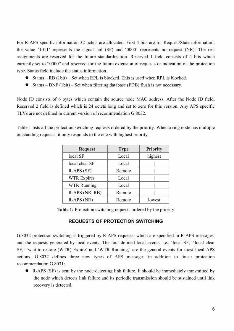
For R-APS specific information 32 octets are allocated. First 4 bits are for Request/State information; the value ‘1011’ represents the signal fail (SF) and ‘0000’ represents no request (NR). The rest assignments are reserved for the future standardization. Reserved 1 field consists of 4 bits which currently set to “0000” and reserved for the future extension of requests or indication of the protection type. Status field include the status information.
� Status – RB (1bit) – Set when RPL is blocked. This is used when RPL is blocked. � Status – DNF (1bit) – Set when filtering database (FDB) flush is not necessary.
Node ID consists of 6 bytes which contain the source node MAC address. After the Node ID field, Reserved 2 field is defined which is 24 octets long and set to zero for this version. Any APS specific TLVs are not defined in current version of recommendation G.8032. Table 1 lists all the protection switching requests ordered by the priority. When a ring node has multiple outstanding requests, it only responds to the one with highest priority.
Request Type Priority local SF Local highest local clear SF Local | R-APS (SF) Remote | WTR Expires Local | WTR Running Local | R-APS (NR, RB) Remote | R-APS (NR) Remote lowest
Table 1: Protection switching requests ordered by the priority
REQUESTS OF PROTECTION SWITCHING G.8032 protection switching is triggered by R-APS requests, which are specified in R-APS messages, and the requests generated by local events. The four defined local events, i.e., ‘local SF,’ ‘local clear SF,’ ‘wait-to-restore (WTR) Expire’ and ‘WTR Running,’ are the general events for most local APS actions. G.8032 defines three new types of APS messages in addition to linear protection recommendation G.8031:
� R-APS (SF) is sent by the node detecting link failure. It should be immediately transmitted by the node which detects link failure and its periodic transmission should be sustained until link recovery is detected.

7
� R-APS (NR) should be transmitted periodically by the node which detects link recovery until R-APS (NR, RB) is received from the RPL owner.
� R-APS (NR, RB) is sent by the RPL owner and indicates that the ring is OK and the RPL is blocked. This message is periodically transmitted on the ring to indicate the normal state.
FAILURE DETECTION
Protection switching occurs on the detection of failure on a link in the ring monitored by Ethernet continuity check (ETH-CC) function [5]. Physical layer (or server layer) failure conditions can be informed to the Ethernet ring protection control. Two end ports of a link form a MEG, and an MEG end point (MEP) function is installed in each ring port. Periodic continuity check message (CCM) exchange is activated between pairing MEPs to monitor the link health. The MEL for link monitoring is assigned to be lower than the MEL of R-APS channel when the MEG levels are shared. The further discussions on Ethernet OAM and applications are presented in [6]. An MEP declares a loss-of-continuity defect when it does not receive the expected CCM for 3.5 times the configured transmission period. When an MEP detects the failure, it signals the ERP control process to initiate protection switchover. A node failure is regarded as the failure of two links attached to the node. The two nodes adjacent to the failed node detect the failure on the links connected to the failed node, and trigger protection switching.
PROTECTION BLOCKING In the normal state, one ring protection link (RPL) is designated and blocks Ethernet traffic to guarantee the loop avoidance. An RPL owner, which is attached to one end of RPL, is designated to performing traffic blocking. The RPL owner sets the port on the RPL as blocked, and thus it drops any client traffic received from or sent to the RPL. The RPL owner plays a very important role in G.8032, as it is responsible for use of the RPL for ring protection switching. When a failure occurs, each node that detects the failure blocks the failed link and sends the R-APS messages with SF indication, i.e., R-APS(SF). The messages are disseminated over the ring. When the RPL owner receives the R-APS(SF) message, it unblocks the blocked port on the RPL to change the topology for achieving maximal connectivity of ring nodes. Eventually, the blocking positions for both R-APS and service traffic are moved from the RPL owner to the nodes that detect the failure.
FDB FLUSH FDB flush is the operation that removes all learned MAC addresses of the ring ports from the forwarding database (FDB). Unlike the previous linear protection and SDH multiplex section protection ring (MSPRing), the protection entity is not preconfigured on the Ethernet ring. G.8032 makes use of the flooding and address learning mechanism of native Ethernet bridging. FDB flush is a way to trigger traffic flooding, and as a result, the service can be kept unbroken and a new forwarding path is set up by

8
self-learning function. The flush operation is exerted only to a client VLAN group bound to a certain ring instance. G.8032 defines several general rules to determine if a node should flush its FDB depending on the ring states:
� If there exists no other request, the detection of a SF condition on a ring node triggers a FDB flush;
� If there exists no other request except R-APS(NR,RB), the initial reception of R-APS(SF) messages triggers a FDB flush; subsequent reception of SF messages shall not trigger further FDB flushes regardless of the source node of the SF messages.
� In the protection state, when the WTR timer expires and the RPL owner blocks the RPL, the RPL owner flushes the FDB;
� In the protection state, the initial reception of R-APS(NR,RB) message triggers a FDB flush on all non-RPL-owner nodes; subsequent receptions of R-APS(NR, RB) messages shall not trigger further FDB flushes.
Since FDB flush is an essential part of protection switching, the aforementioned rules are implemented in the state machine of G.8032.
REVERSION After recovery from all failures, the port blocking is changed back to the RPL owner in the revertive operation. Since the position of the RPL might optimize the use of network resources, the revertive operation can be desirable. However, it costs an additional glitch in traffic services. In order to avoid an erroneous switching operation that may be caused by intermittent failures, a WTR timer is adopted. When the RPL owner recognizes the failure recovery by receiving an R-APS(NR) message from a node at one end of a recovered link, it starts the WTR timer. If any failure detected locally or remotely before expiration of the WTR timer, the WTR timer and the reversion process are aborted. When it expires, the RPL owner blocks its end of the RPL, and instructs the node connected to the recovered link to remove its block by sending an R-APS(NR,RB) message.
A SAMPLE SCENARIO WITH MULTIPLE FAILURE AND RECOVERY
Figure 4 illustrates a scenario in the case of multiple failures and recovery which shows ERP processes as follows:

9
1. In the normal state, the PRL-Owner block is in place at its port connected to RPL. 2. When Nodes C and D detect the local SF condition, each node flushes its FDB, blocks the failed
port, and transmits an R-APS(SF) message on both ring ports, followed by periodic transmission of the same messages, while the SF condition persists. Other nodes flush FDBs on receiving the R-APS(SF) message.
3. When it receives an R-APS(SF) message, the RPL owner flushes FDB and unblocks its port on the RPL.
4. Further failures occur at the links between Nodes A and B and between Nodes E and F. Four nodes block their failed ports and transmit R-APS (SF) messages. Other nodes do not perform FDB flush as the prior SF condition exists.
5. The failed links between Nodes A and B and between E and F recover concurrently. Nodes A, B, E and F send periodic R-APS(NR) messages.
NR
NR
RPL
recovery
R-APS channel block Client channel blockMessage source
NR RB
SFSFSF
NRNR
A B C D E F G
SF
recovery5
SF
NR
SF SF SF
NR NR NR6
SF
SF SFSF SF7
SF8
SFSFSFSF
SFSFSFSFSFX
recoveryNR NR
9
NRNRNR NR
10
11NR RB
12
NR NR
RPL Owner
NR RB
NR RB
NR RB
NR RBNR RBNR RBNR RBNR RB
NR RB NR RB NR RBNR RB NR RB
1failure SFSF2
3SF SF
SF SF
SF SF SFSFSF
failurefailure4
NRNR
NRNRNRNR NR NR NR
NR
NR
RPL
recovery
R-APS channel block Client channel blockMessage source
NR RB
SFSFSF
NRNR
A B C D E F G
SF
recovery5
SF
NR
SF SF SF
NR NR NR6
SF
SF SFSF SF7
SF8
SFSFSFSF
SFSFSFSFSFX
recoveryNR NR
9
NRNRNR NR
10
11NR RB
12
NR NR
RPL Owner
NR RB
NR RB
NR RB
NR RBNR RBNR RBNR RBNR RB
NR RB NR RB NR RBNR RB NR RB
1failure SFSF2
3SF SF
SF SF
SF SF SFSFSF
failurefailure4
NRNR
NRNRNRNR NR NR NR
Figure 4: An example sequence diagram of multiple link failure and recovery
10
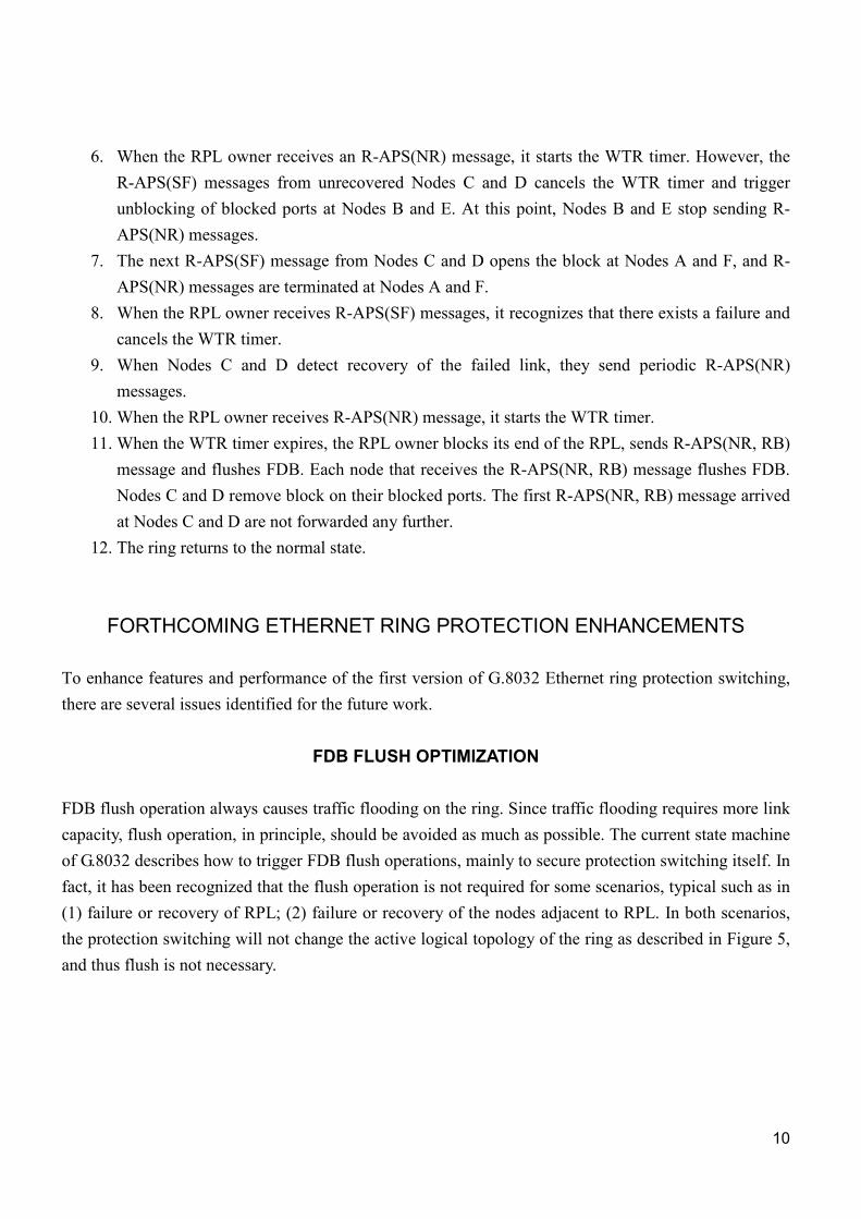
6. When the RPL owner receives an R-APS(NR) message, it starts the WTR timer. However, the R-APS(SF) messages from unrecovered Nodes C and D cancels the WTR timer and trigger unblocking of blocked ports at Nodes B and E. At this point, Nodes B and E stop sending R-APS(NR) messages.
7. The next R-APS(SF) message from Nodes C and D opens the block at Nodes A and F, and R-APS(NR) messages are terminated at Nodes A and F.
8. When the RPL owner receives R-APS(SF) messages, it recognizes that there exists a failure and cancels the WTR timer.
9. When Nodes C and D detect recovery of the failed link, they send periodic R-APS(NR) messages.
10. When the RPL owner receives R-APS(NR) message, it starts the WTR timer. 11. When the WTR timer expires, the RPL owner blocks its end of the RPL, sends R-APS(NR, RB)
message and flushes FDB. Each node that receives the R-APS(NR, RB) message flushes FDB. Nodes C and D remove block on their blocked ports. The first R-APS(NR, RB) message arrived at Nodes C and D are not forwarded any further.
12. The ring returns to the normal state.
FORTHCOMING ETHERNET RING PROTECTION ENHANCEMENTS To enhance features and performance of the first version of G.8032 Ethernet ring protection switching, there are several issues identified for the future work.
FDB FLUSH OPTIMIZATION FDB flush operation always causes traffic flooding on the ring. Since traffic flooding requires more link capacity, flush operation, in principle, should be avoided as much as possible. The current state machine of G.8032 describes how to trigger FDB flush operations, mainly to secure protection switching itself. In fact, it has been recognized that the flush operation is not required for some scenarios, typical such as in (1) failure or recovery of RPL; (2) failure or recovery of the nodes adjacent to RPL. In both scenarios, the protection switching will not change the active logical topology of the ring as described in Figure 5, and thus flush is not necessary.

11
2 1 6
3 4 5
2 1 6
3 4 5
2 1 6
3 4 5
2 1 6
3 4 5
2 1 6
3 4 5
2 1 6
3 4 5
2 1 6
3 4 5
2 1 6
3 4 5
RPL RPL RPL RPL
Ring Topology
Active Topology
Ring Topology
Active Topology
Figure 5: RPL link/node failure and recovery
As aforementioned, a “do-not-flush (DNF)” indication in the R-APS specification information is used for FDB flush optimization by suppressing the FDB flush operation. The usage of this indication will be defined in future. As an example, when a node detects a RPL link/node failure, it will send R-APS messages with DNF indication which just trigger state transition without FDB flush.
FDB FLIP FDB flip is an alternative technique that can replace FDB flush and is currently being considered in G.8032. On FDB flush after replacing a new blocking either due to a failure or for reversion, all client traffic is broadcast as there is no address filtering information in the FDB. This results in a traffic flooding that creates a traffic volume several times greater than the steady traffic that can be achieved after FDB completes address learning [7]. When such flooding traffic volume is far greater than the link capacity, majority of frames are lost or delayed due to queuing in a buffer. In this situation, two-fold network impairments manifests; extended delay and increase loss of client traffic. In addition, the burst of traffic flooding extends the address learning period. Combination of all these penalty can extend APS switching and settlement time longer than 50 ms. This phenomenon can be critical when a ring provides services to a large number of hosts. In the proposed FDB flip method an R-APS flip message contains information how the FDBs at other nodes should be modified so that the FDBs provide optimized forwarding immediately, as described in [7].
NON-REVERTIVE MODE WITH PRIORITY MECHANISM In the non-revertive mode, the blocked ports are not returned to the RPL owner even though all failure links have recovered. Afterwards, the operator can trigger the reversion by a command. In the case of single link failure, the blocked ports can remain blocked, which can be achieved without any

12
complication. However, when multiple links recover concurrently from failure, all but one recovered links should be unblocked. In order to select the only one node which does not unblock its port, a priority-based non-revertive mechanism is proposed and being considered for the future study of G.8032. In the non-revertive mode, nodes adjacent to a recovery will send R-APS(NR) messages with the priority information of the link or node. Other node receiving this R-APS(NR) compares its link or node priority with the priority indicated in the message. If it is lower, then the node can unblock the port. The link/node priority can consist of 6 bytes of information to contain either the MAC address of port or the “Node ID” defined in G.8032. The priority assignment remained as the further study.
RPL REPLACEMENT The RPL can be changed permanently to any other link than the original RPL. The RPL replacement command moves the position of the RPL by blocking a ring link and unblocking the RPL permanently. Also the functionality of the RPL Owner is transferred to the corresponding node that is connected to the new RPL.
MANUAL SWITCH AND FORCE SWITCH
In addition to the failures detected locally or remotely, operator controls can initiates protection switching. The examples of the switchover that may be administratively triggered are Manual Switch and Force Switch. The Manual Switch is used to move the blocked port from the RPL to a different ring link when there is no failure in the ring, and Force Switch is to move the blocking port from the RPL to a different ring link no matter if there exists any failure in the ring or not. The Manual Switch and the Force Switch are removed by administratively issuing a Clear command. The ring then will switch back to normal state. As opposed to the RPL replacement, the Manual Switch and the Force Switch are considered as temporary commands and do not change the location of the RPL permanently. The operations of Manual Switch and Force Switch will be studied and determined in the next version of Ethernet ring protection.
DUAL END BLOCKING
In current G.8032, one end of the RPL is blocked for breaking the loop in normal state. In this case, the traffic would be flooded on the link from the unblocked end. RPL capacity is always wasted by the flooded traffic. It is not a problem when the ring is occupied by only one ring instance. But in many cases, there may be several ERP instances or other kind of services sharing the link. The traffic flooded on the RPL link would contend for bandwidth resource with other services.
13
A way to avoid the flooding on the RPL is to block its both ends in normal state. When a failure occurs, both blocked ports will be opened for traffic protection. Similarly, when unidirectional failure occurs, both of the ends also should be blocked. In this case, Ethernet remote defect indication (ETH-RDI) [5] may be used as indication of unidirectional defect. To synchronize the configuration of the two ports on the RPL, it is suggested that one end of RPL is provisioned in the normal state and another end is automatically determined by network management system (NMS) or other initialization mechanism. The new mechanism should be compatible with that of single end blocking architecture.
CONCLUSIONS Based on recent progress in Ethernet technology, standards, applications and initial deployment, Ethernet is posed to be the next packet infrastructure for many metro service providers. Given the dominance of rings, e.g., wavelength-division multiplexing (WDM) and SONET/SDH, in both the access and metro networks, an Ethernet ring solution is an attractive upgrade strategy. G.8032 ERP can realize fast and economic solution to provide carrier-class protection for Ethernet ring networks, without defining any new Ethernet forwarding and filtering functions on data path. G.8032 is simply an incremental software change that allows the service provider to leverage its existing installed Ethernet switches. As the ERP is designed to be independent of the capability of the server layer transmission media, this new ring protection for Ethernet can run over any server layer networks that any network operator might have. Since G.8032 ERP can support heterogeneous rings, which means not all the ring spans need be the same bandwidth nor physical layer, this means that upgrade strategies is possible with ERP. For example, as RPR requires that all the ring spans need to be the same bandwidth, ring bandwidth upgrades are more difficult. This difficulty pushes us into RPR stacking topologies, which is difficult to manage. The ERP also achieves efficient bandwidth utilization of ring traffic by means of spatial reuse. With these advantages, it is expected that the ERP will be an efficient, deployable and economically viable solution for carrier class Ethernet ring networks in the very near future.
14
REFERENCES [1] Infonetics Research, “Service Provider Plans for Metro Optical and Ethernet: North America, Europe, and
Asia Pacific 2007,” September 2007.
[2] ITU-T Rec. G.8032, “Ethernet Ring Protection Switching,” 2008.
[3] IEEE Standard 802.17, “Part17: Resilient Packet Ring (RPR) access method and physical specifications,”
2004.
[4] IEEE Standard 802.1Q, “Virtual Bridged Local Area Networks,” 2005.
[5] ITU-T Rec. Y.1731, “OAM Functions and Mechanisms for Ethernet Based Networks,” 2006.
[6] J. Ryoo et al., “OAM and Its Performance Monitoring Mechanisms for Carrier Ethernet Transport Networks,”
IEEE Commun. Mag., March 2008, pp. 97-103.
[7] Jinsung Im, Jeong-dong Ryoo, and J.-K. Kevin Rhee, “Managed FDB Algorithm and Protection in Ethernet
Ring Topology,” Proc. of COIN-ACOFT 2007, Paper WeC1-1, June 2007.
BIOGRAPHIES
JEONG-DONG RYOO ([email protected]) is a principal member of research staff in Electronics and
Telecommunications Research Institute (ETRI), South Korea. He holds Master’s and Ph.D. degrees in electrical
engineering from Polytechnic University, Brooklyn, NY, and a Bachelor’s degree in electronic engineering from
Kyungpook National University, South Korea. After completing his Ph. D. study in the area of telecommunication
networks and optimization, he started working for Bell Labs, Lucent Technologies, New Jersey, in 1999. While he
was with Bell Labs, he was mainly involved with performance analysis/evaluation/enhancement study for various
wireless and wired network systems. Since he left Bell Labs and joined ETRI in 2004, his work has been focused
on next generation network and carrier class Ethernet technology research, especially participating in OAM and
protection standardization activities in ITU-T. He co-authored TCP/IP Essentials: A Lab-Based Approach
(Cambridge University Press, 2004). He is a member of Eta Kappa Nu.