Estimation of bored pile capacity and settlement in soft soils
18
Građevinar 10/2013 901 GRAĐEVINAR 65 (2013) 10, 901-918 UDK 624.154.001.2:624.044/.46 Prof. Tomislav Ivšić, PhD. CE University of Zagreb Faculty of Civil Engineering Department of Geotechnical Engineering [email protected] Mario Bačić, B.Sc. CE University of Zagreb Faculty of Civil Engineering Department of Geotechnical Engineering [email protected] Lovorka Librić, B.Sc. CE University of Zagreb Faculty of Civil Engineering Department of Geotechnical Engineering [email protected] Subject review Tomislav Ivšić, Mario Bačić, Lovorka Librić Estimation of bored pile capacity and settlement in soft soils Although the technologies of pile construction are improving, the problems of load capacity and settlements determination are still present, where estimation methods are mostly a combination of theory and empiricism. This paper analyzes the bearing capacity and settlement of bored piles, as the most frequently used type of piles in local practice. Empirical methods based on geotechnical soil parameters for capacity estimation, introduce some simplifications which lead to neglecting certain elements of a complex pile-soil interaction. On the other hand, the results of pile field testing methods are a direct summary consequence of the overall complex conditions on pile-soil contact. Key words: bored piles, pile capacity, pile settlement, empirical estimation of capacity, field testing of piles Pregledni rad Tomislav Ivšić, Mario Bačić, Lovorka Librić Procjene nosivosti i slijeganja bušenih pilota u mekim tlima Iako se tehnologije izvedbe pilota sve više usavršavaju, problemi procjene nosivosti i slijeganja su i dalje prisutni, pri čemu metode procjene u znatnoj mjeri predstavljaju kombinaciju teorije i empirije. U radu se analizira nosivost i slijeganje bušenih pilota, kao najčešće korištenog tipa pilota u domaćoj praksi. Empirijske metode procjene nosivosti iz geotehničkih parametara tla uvode niz određenih pojednostavljenja, čime se izostavljaju pojedini elementi složene interakcije pilot-tlo. S druge strane, rezultati terenskih ispitivanja pilota su izravna zbirna posljedica složenih sveukupnih uvjeta na kontaktu tla i pilota. Ključne riječi: bušeni piloti, nosivost pilota, slijeganje pilota, empirijske procjene nosivosti, terenska ispitivanja pilota Übersichtsarbeit Tomislav Ivšić, Mario Bačić, Lovorka Librić Einschätzung der Tragfähigkeit und Setzungen von Bohrpfählen in weichen Böden Obwohl die Technologie der Pfahlkonstruktion stetig verbessert wird, sind Probleme bezüglich der Bestimmung von Tragfähigkeit und Setzungen weiterhin vorhanden. Einschätzungsmethoden beinhalten meistens eine Kombination von Theorie und Empirie. In dieser Arbeit werden Tragfähigkeit und Setzungen von häufig in der regionalen Praxis angewandten Bohrpfählen analysiert. Empirische Methoden, die auf Einschätzungen der Tragfähigkeit anhand geotechnischer Bodenparameter beruhen, beinhalten eine Reihe von Vereinfachungen und sehen über bestimmte Elemente der komplexen Pfahl-Boden-Interaktion hinweg. Die Resultate von Feldversuchen stellen dagegen eine direkte Zusammenfassung der Auswirkungen komplexer Zustände am Kontakt zwischen Pfahl und Boden dar. Schlüsselwörter: Bohrpfähle, Pfahltragfähigkeit, Pfahlsetzung, empirische Tragfähigkeitseinschätzung, Feldversuche an Pfählen Estimation of bored pile capacity and settlement in soft soils Primljen / Received: 2.7.2013. Ispravljen / Corrected: 15.10.2013. Prihvaćen / Accepted: 21.10.2013. Dostupno online / Available online: 10.11.2013. Authors:
Transcript of Estimation of bored pile capacity and settlement in soft soils
Građevinar 10/2013
901GRAĐEVINAR 65 (2013) 10, 901-918
UDK 624.154.001.2:624.044/.46
Prof. Tomislav Ivšić, PhD. CEUniversity of Zagreb Faculty of Civil Engineering Department of Geotechnical [email protected]
Mario Bačić, B.Sc. CEUniversity of Zagreb Faculty of Civil Engineering Department of Geotechnical [email protected]
Lovorka Librić, B.Sc. CEUniversity of Zagreb Faculty of Civil Engineering Department of Geotechnical [email protected]
Subject reviewTomislav Ivšić, Mario Bačić, Lovorka Librić
Estimation of bored pile capacity and settlement in soft soils
Although the technologies of pile construction are improving, the problems of load capacity and settlements determination are still present, where estimation methods are mostly a combination of theory and empiricism. This paper analyzes the bearing capacity and settlement of bored piles, as the most frequently used type of piles in local practice. Empirical methods based on geotechnical soil parameters for capacity estimation, introduce some simplifications which lead to neglecting certain elements of a complex pile-soil interaction. On the other hand, the results of pile field testing methods are a direct summary consequence of the overall complex conditions on pile-soil contact.
Key words:bored piles, pile capacity, pile settlement, empirical estimation of capacity, field testing of piles
Pregledni radTomislav Ivšić, Mario Bačić, Lovorka Librić
Procjene nosivosti i slijeganja bušenih pilota u mekim tlima
Iako se tehnologije izvedbe pilota sve više usavršavaju, problemi procjene nosivosti i slijeganja su i dalje prisutni, pri čemu metode procjene u znatnoj mjeri predstavljaju kombinaciju teorije i empirije. U radu se analizira nosivost i slijeganje bušenih pilota, kao najčešće korištenog tipa pilota u domaćoj praksi. Empirijske metode procjene nosivosti iz geotehničkih parametara tla uvode niz određenih pojednostavljenja, čime se izostavljaju pojedini elementi složene interakcije pilot-tlo. S druge strane, rezultati terenskih ispitivanja pilota su izravna zbirna posljedica složenih sveukupnih uvjeta na kontaktu tla i pilota.
Ključne riječi:bušeni piloti, nosivost pilota, slijeganje pilota, empirijske procjene nosivosti, terenska ispitivanja pilota
ÜbersichtsarbeitTomislav Ivšić, Mario Bačić, Lovorka Librić
Einschätzung der Tragfähigkeit und Setzungen von Bohrpfählen in weichen Böden
Obwohl die Technologie der Pfahlkonstruktion stetig verbessert wird, sind Probleme bezüglich der Bestimmung von Tragfähigkeit und Setzungen weiterhin vorhanden. Einschätzungsmethoden beinhalten meistens eine Kombination von Theorie und Empirie. In dieser Arbeit werden Tragfähigkeit und Setzungen von häufig in der regionalen Praxis angewandten Bohrpfählen analysiert. Empirische Methoden, die auf Einschätzungen der Tragfähigkeit anhand geotechnischer Bodenparameter beruhen, beinhalten eine Reihe von Vereinfachungen und sehen über bestimmte Elemente der komplexen Pfahl-Boden-Interaktion hinweg. Die Resultate von Feldversuchen stellen dagegen eine direkte Zusammenfassung der Auswirkungen komplexer Zustände am Kontakt zwischen Pfahl und Boden dar.
Schlüsselwörter:Bohrpfähle, Pfahltragfähigkeit, Pfahlsetzung, empirische Tragfähigkeitseinschätzung, Feldversuche an Pfählen
Estimation of bored pile capacity and settlement in soft soils
Primljen / Received: 2.7.2013.
Ispravljen / Corrected: 15.10.2013.
Prihvaćen / Accepted: 21.10.2013.
Dostupno online / Available online: 10.11.2013.
Authors:

Građevinar 10/2013
902 GRAĐEVINAR 65 (2013) 10, 901-918
Tomislav Ivšić, Mario Bačić, Lovorka Librić
1. Introduction
Piles as a foundation method have been a part of the construction tradition for thousands of years. Pile dwellings in marshy terrains along lakes and in river inundations used to be quite common in Central Europe already in the Bronze Age. Reconstructed prehistoric pile dwelling settlements located in six Alpine states have been under UNESCO protection since 2011.Written records from ancient Rome show that in these times piles were used as a "routine" technology. In the records on Gallic Wars, Caesar [1] writes about construction of the bridge over the Rhine where wooden (raking or vertical) piles of 6 inches (about 45 cm) in diameter were driven into the riverbed by machines. Approximately at the same time Vitruvius [2] writes his Ten Books of Architecture where he offers practical advice on construction work, and specifically mentions piles for the foundation work in soft soils. Two pile types are differentiated in Roman times: a) palis (pointed posts 10 - 15 cm in diameter, 50 - 70 cm in length) that were densely driven into soil by a hand-held hammer in order to strengthen the soil immediately beneath foundation beams and walls, and b) sublicae, thicker and longer round timber piles driven-in by machines down to the deeper load bearing soil layers. In Roman literature, the use of piles is mentioned with regard to foundation work for bridges, buildings, coastal structures and fortifications built in a wider area of the empire, from Roman Britain to Anatolia [3]. The pile driving technology has been applied throughout the history and also on structures built in Middle Ages (e.g. Venice, Amsterdam).Driven timber piles were practically the only pile type in use until the second half of the 19th century when other materials were introduced, as well as steam machines, and later on diesel machines (hammers), for pile driving. The idea of bored piles initially originated from the deep well driving procedure (primarily for drinking water, and later on as elements of deep massive foundations). Bored piles were fully developed in 1950’s and 1960’s with the development of construction machines (out of machines used on oil wells), when it became possible to economically drill stabilized boreholes of greater diameters, even under the groundwater level. There are currently over sixty commercial piling techniques, as in [4] for instance, out of which over sixty percent are various pile driving procedures. It is indicated in recent reviews [5] that the use of bored piles is becoming more widespread, and so it reached 50 percent around the year 2000. It should however be noted that the distribution of all pile types is not uniform on an international scale, and that it greatly depends on local traditions and markets.Piles are primarily constructed in zones where the foundation soil near the ground surface does not have sufficient resistance or stiffness, and so it can not take on forces from the structure above, without great displacements or failure. The necessary depth of piles in foundation soil layers is determined by requirements specifying acceptable resistance and displacement values. According to millenary experience in pile driving, wooden posts or columns were driven until further penetration proved impossible. This situation, known as refusal, is a combination of
soil layers and limitations of pile driving equipment, and can be regarded as a sort of empirical confirmation of bearing capacity and settlement. Traditionally, the pile capacity determination was based on experience and it strongly relied on the constructor’s previous knowledge and expertise.Engineers are nowadays required to determine, at the design stage, dimensions of structural bearing elements, and to provide evidence or guarantees about sufficient resistance to expected actions. In this respect, dimensioning of piles for various construction technologies, and a sufficiently accurate estimation of bearing capacity and settlement of piles, involve preliminary analysis of composition and properties of the foundation soil, "calculation" i.e. numerical description (simulation) of mechanical behaviour, and the pile load testing (as the only valid confirmation). On smaller projects where construction budget is modest, the pile load testing is too expensive, and so it is expected that pile dimensions are determined and confirmed by calculation.In most ordinary civil engineering structures, calculations and standard technical specifications for materials and construction work are regarded as a sufficiently reliable confirmation of dimensions of structural elements, because theoretical bases for calculation and standardized properties of materials enable a sufficiently accurate numerical description of behaviour. In geotechnical engineering and design, the accuracy of usual numerical models is lower (and so is the reliability of confirmation by calculation) because of the complex soil and rock behaviour, range of parameters and heterogeneity, and interaction between artificial and natural materials. That is why the calculation (or better to say "estimation") of pile capacity and settlement is even today to a great extent a mixture of theory and empiricism [6, 7, 8].
2. Problem definition
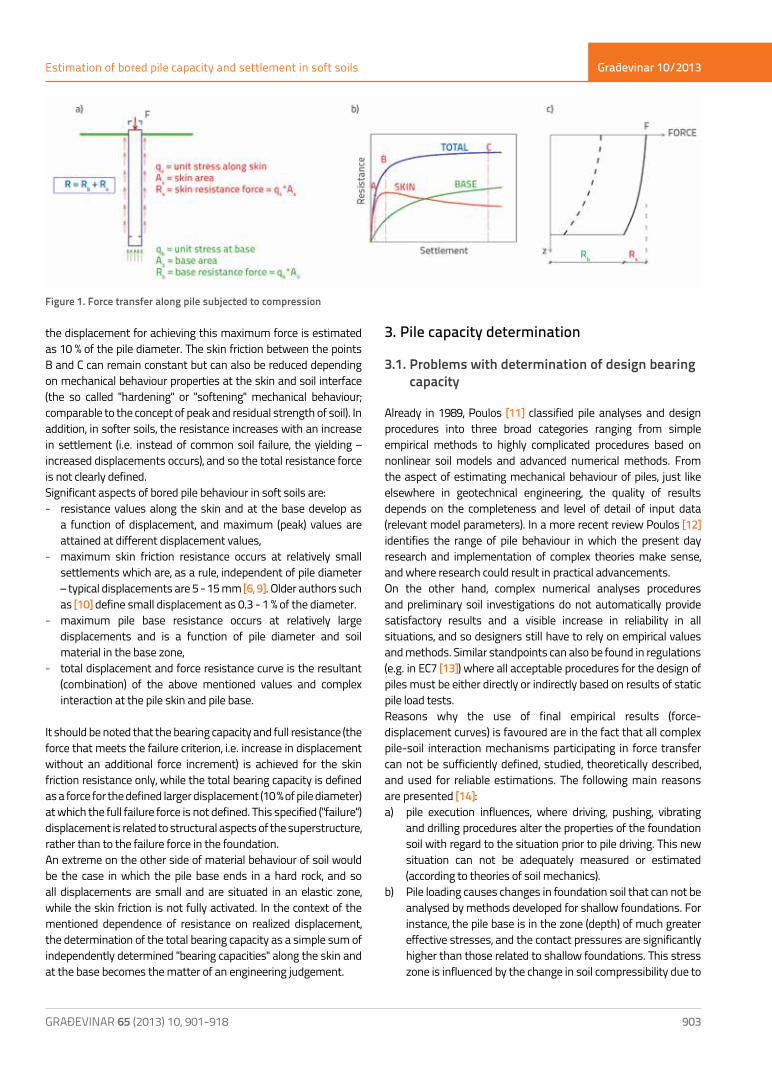
Piles in soft soils, which transfer force both along the skin and at the base, are primarily considered in this paper. Basic behavioural aspects of a pile subjected to axial compressive force, i.e. elements of force transfer into the foundation soil, are presented in Figure 1. General relationships between the pile resistance and settlement are presented in Figure 1b where three resistance components are presented: 1. skin friction resistance (Rs), 2. base resistance (Rb) and 3. combined (total) resistance. An idealised distribution of vertical (axial) force along the depth is presented for different displacement values in Figure 1c.
As the force on the pile top (F) increases, the pile settles and mobilises the skin friction resistance (point A in Figure 1b). The transfer of force to the surrounding soil results in force reduction across the pile depth (dashed line in Figure 1c). Initially, the force is dominantly transferred by skin friction and the part of the force transferred to the base is relatively small. The full skin friction mobilises with an increase in force (point B). Further increase in force after the point B will be taken over at the pile base only, until the maximum combined resistance is achieved (point C), where
Građevinar 10/2013
903GRAĐEVINAR 65 (2013) 10, 901-918
Estimation of bored pile capacity and settlement in soft soils
the displacement for achieving this maximum force is estimated as 10 % of the pile diameter. The skin friction between the points B and C can remain constant but can also be reduced depending on mechanical behaviour properties at the skin and soil interface (the so called "hardening" or "softening" mechanical behaviour; comparable to the concept of peak and residual strength of soil). In addition, in softer soils, the resistance increases with an increase in settlement (i.e. instead of common soil failure, the yielding – increased displacements occurs), and so the total resistance force is not clearly defined.Significant aspects of bored pile behaviour in soft soils are: - resistance values along the skin and at the base develop as
a function of displacement, and maximum (peak) values are attained at different displacement values,
- maximum skin friction resistance occurs at relatively small settlements which are, as a rule, independent of pile diameter – typical displacements are 5 - 15 mm [6, 9]. Older authors such as [10] define small displacement as 0.3 - 1 % of the diameter.
- maximum pile base resistance occurs at relatively large displacements and is a function of pile diameter and soil material in the base zone,
- total displacement and force resistance curve is the resultant (combination) of the above mentioned values and complex interaction at the pile skin and pile base.
It should be noted that the bearing capacity and full resistance (the force that meets the failure criterion, i.e. increase in displacement without an additional force increment) is achieved for the skin friction resistance only, while the total bearing capacity is defined as a force for the defined larger displacement (10 % of pile diameter) at which the full failure force is not defined. This specified ("failure") displacement is related to structural aspects of the superstructure, rather than to the failure force in the foundation.An extreme on the other side of material behaviour of soil would be the case in which the pile base ends in a hard rock, and so all displacements are small and are situated in an elastic zone, while the skin friction is not fully activated. In the context of the mentioned dependence of resistance on realized displacement, the determination of the total bearing capacity as a simple sum of independently determined "bearing capacities" along the skin and at the base becomes the matter of an engineering judgement.
3. Pile capacity determination
3.1. Problems with determination of design bearing capacity
Already in 1989, Poulos [11] classified pile analyses and design procedures into three broad categories ranging from simple empirical methods to highly complicated procedures based on nonlinear soil models and advanced numerical methods. From the aspect of estimating mechanical behaviour of piles, just like elsewhere in geotechnical engineering, the quality of results depends on the completeness and level of detail of input data (relevant model parameters). In a more recent review Poulos [12] identifies the range of pile behaviour in which the present day research and implementation of complex theories make sense, and where research could result in practical advancements.On the other hand, complex numerical analyses procedures and preliminary soil investigations do not automatically provide satisfactory results and a visible increase in reliability in all situations, and so designers still have to rely on empirical values and methods. Similar standpoints can also be found in regulations (e.g. in EC7 [13]) where all acceptable procedures for the design of piles must be either directly or indirectly based on results of static pile load tests.Reasons why the use of final empirical results (force-displacement curves) is favoured are in the fact that all complex pile-soil interaction mechanisms participating in force transfer can not be sufficiently defined, studied, theoretically described, and used for reliable estimations. The following main reasons are presented [14]:a) pile execution influences, where driving, pushing, vibrating
and drilling procedures alter the properties of the foundation soil with regard to the situation prior to pile driving. This new situation can not be adequately measured or estimated (according to theories of soil mechanics).
b) Pile loading causes changes in foundation soil that can not be analysed by methods developed for shallow foundations. For instance, the pile base is in the zone (depth) of much greater effective stresses, and the contact pressures are significantly higher than those related to shallow foundations. This stress zone is influenced by the change in soil compressibility due to
Figure 1. Force transfer along pile subjected to compression

Građevinar 10/2013
904 GRAĐEVINAR 65 (2013) 10, 901-918
Tomislav Ivšić, Mario Bačić, Lovorka Librić
grain crushing and change (reduction) in the angle of friction, and so the linear soil failure envelope is generally not relevant.
c) Direct mechanism of force transfer from the pile head to the surrounding soil and soil below the base is still not fully explained, and so explanations given to this effect are sometimes quite contradictory [14]. For instance, arch effects during transfer of compressive forces in the top part of the pile can increase skin friction in the central part, and reduce it in the bottom part [15, 16] (Figure 2a).
The opposite effect may occur due to local extrusion of soil under the pile base in the upward direction, during settlement (driving) of the pile, and also due to dilation of dense soil during shear. These effects cause an increase in lateral pressure in the part of the pile around the base, and hence also a higher skin friction (Figure 2b). As a comparison, the skin friction of tension piles in the same soil is not influenced by these mechanisms, and it should therefore be lower than that of compression piles [14]. This standpoint and some measurement results were also formulated by O’Neill [6]. This provoked reaction from other authors who consider that the pile skin friction is independent of the direction of force applied on the pile [17, 18] and, consequently, that mechanisms shown in Figure 2 are not significant for the distribution of friction along the skin. As the experimental confirmation is for now ambiguous, this aspect is still awaiting its final explanation.Although attempts are being made to objectivise the influence of pile execution procedure through measurements, such experiments are still quite rare and insufficiently systematic. As an illustration, some results are presented in Figures 3 and 4. The influence of soil stress relaxation after borehole drilling for a pile 1 m in diameter is presented in Figure 3. According to shear wave velocity measurements, the velocity is by about 30 percent lower next to borehole compared to velocity in the surrounding soil. This influence spreads to the distance of about 1 - 1.5 borehole diameters. As the undrained strength is correlated with shear modulus, i.e. velocity squared, this measurement shows that the drilling has
caused disturbance, and that the relevant strength of soil has been significantly reduced at the interface. More specifically, here the measurements confirm the use of empirical coefficient a for the determination of skin friction in coherent materials.
Figure 3. Influence of borehole drilling on shear modulus at small deformations, for bored piles at a University of Houston location (overconsolidated clay) [6]
The behaviour at the interface between the pile and the surrounding soil, i.e. skin friction, is dependent on several factors, and especially on soil properties, skin roughness, stress, and velocity of the shearing process, and also on features specific to each particular pile execution procedure. Even in cased pile boreholes, a void may temporarily be left at the interface during extraction of casing tubes. Depending on the consistency and level of stress in the concrete and soil, the soil moves into the fresh concrete (soil loosening), or the fresh concrete penetrates into the soil (thus increasing the level of stress in the surrounding soil), or both effects occur at various depths or in various soil layers along the pile length.The experimental study on the strength of interface between the concrete skin and hard clay is presented by Moormann [19]. The toothed casing (often used by German contractors to protect boreholes, even in clay) rotates or oscillates during the lifting process,
Figure 2. Transfer of force from pile head into the surrounding soil – different effects and explanations [14]
Građevinar 10/2013
905GRAĐEVINAR 65 (2013) 10, 901-918
Estimation of bored pile capacity and settlement in soft soils
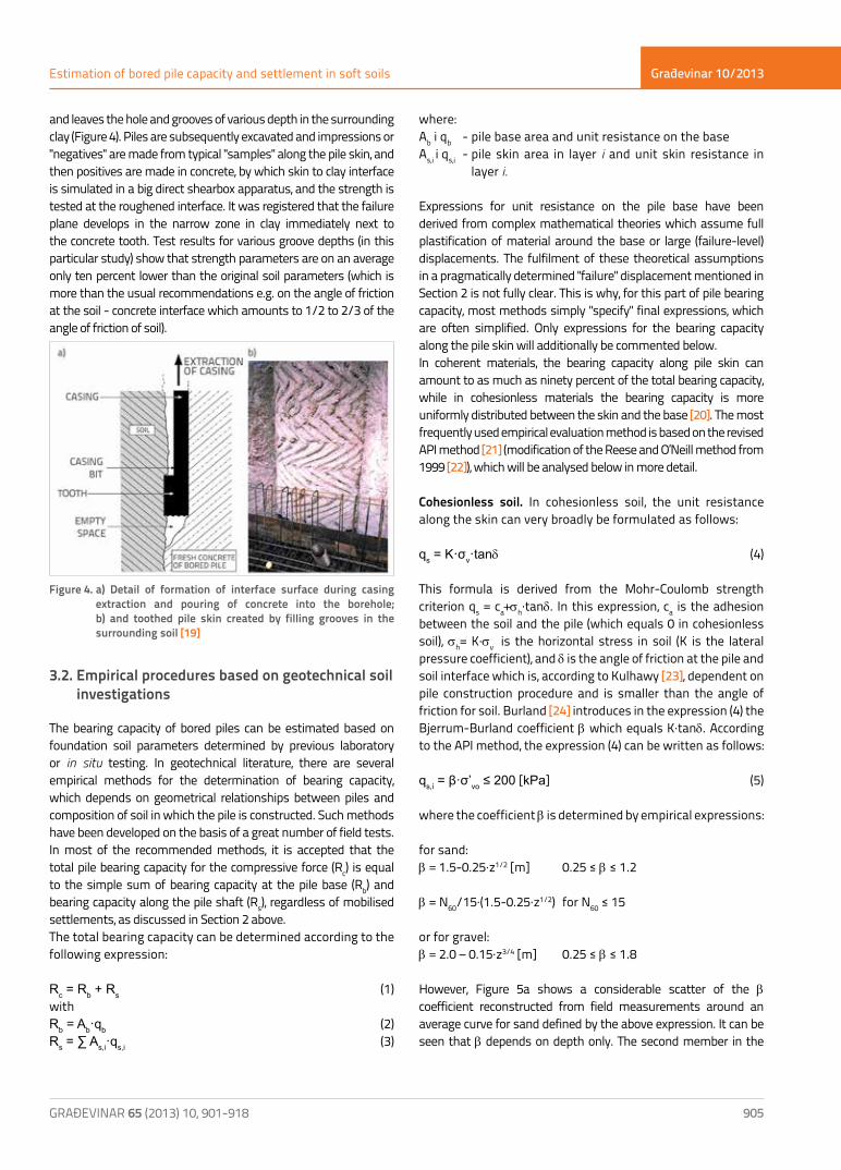
and leaves the hole and grooves of various depth in the surrounding clay (Figure 4). Piles are subsequently excavated and impressions or "negatives" are made from typical "samples" along the pile skin, and then positives are made in concrete, by which skin to clay interface is simulated in a big direct shearbox apparatus, and the strength is tested at the roughened interface. It was registered that the failure plane develops in the narrow zone in clay immediately next to the concrete tooth. Test results for various groove depths (in this particular study) show that strength parameters are on an average only ten percent lower than the original soil parameters (which is more than the usual recommendations e.g. on the angle of friction at the soil - concrete interface which amounts to 1/2 to 2/3 of the angle of friction of soil).
Figure 4. a) Detail of formation of interface surface during casing extraction and pouring of concrete into the borehole; b) and toothed pile skin created by filling grooves in the surrounding soil [19]
3.2. Empirical procedures based on geotechnical soil investigations
The bearing capacity of bored piles can be estimated based on foundation soil parameters determined by previous laboratory or in situ testing. In geotechnical literature, there are several empirical methods for the determination of bearing capacity, which depends on geometrical relationships between piles and composition of soil in which the pile is constructed. Such methods have been developed on the basis of a great number of field tests. In most of the recommended methods, it is accepted that the total pile bearing capacity for the compressive force (Rc) is equal to the simple sum of bearing capacity at the pile base (Rb) and bearing capacity along the pile shaft (Rs), regardless of mobilised settlements, as discussed in Section 2 above.The total bearing capacity can be determined according to the following expression:
Rc = Rb + Rs (1)withRb = Ab·qb (2)Rs = ∑ As,i·qs,i (3)
where: Ab i qb - pile base area and unit resistance on the baseAs,i i qs,i - pile skin area in layer i and unit skin resistance in
layer i.
Expressions for unit resistance on the pile base have been derived from complex mathematical theories which assume full plastification of material around the base or large (failure-level) displacements. The fulfilment of these theoretical assumptions in a pragmatically determined "failure" displacement mentioned in Section 2 is not fully clear. This is why, for this part of pile bearing capacity, most methods simply "specify" final expressions, which are often simplified. Only expressions for the bearing capacity along the pile skin will additionally be commented below.In coherent materials, the bearing capacity along pile skin can amount to as much as ninety percent of the total bearing capacity, while in cohesionless materials the bearing capacity is more uniformly distributed between the skin and the base [20]. The most frequently used empirical evaluation method is based on the revised API method [21] (modification of the Reese and O’Neill method from 1999 [22]), which will be analysed below in more detail.
Cohesionless soil. In cohesionless soil, the unit resistance along the skin can very broadly be formulated as follows:
qs = K·σv·tanδ (4)
This formula is derived from the Mohr-Coulomb strength criterion qs = ca+sh·tanδ. In this expression, ca is the adhesion between the soil and the pile (which equals 0 in cohesionless soil), sh= K·sv is the horizontal stress in soil (K is the lateral pressure coefficient), and δ is the angle of friction at the pile and soil interface which is, according to Kulhawy [23], dependent on pile construction procedure and is smaller than the angle of friction for soil. Burland [24] introduces in the expression (4) the Bjerrum-Burland coefficient b which equals K·tanδ. According to the API method, the expression (4) can be written as follows:
qs,i = β·σ’vo ≤ 200 [kPa] (5)
where the coefficient b is determined by empirical expressions:
for sand:b = 1.5-0.25·z1/2 [m] 0.25 ≤ b ≤ 1.2
b = N60/15·(1.5-0.25·z1/2) for N60 ≤ 15
or for gravel:b = 2.0 – 0.15·z3/4 [m] 0.25 ≤ b ≤ 1.8
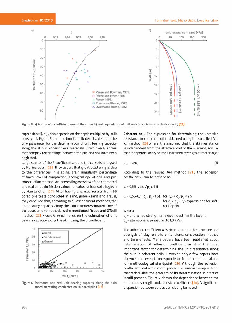
However, Figure 5a shows a considerable scatter of the b coefficient reconstructed from field measurements around an average curve for sand defined by the above expression. It can be seen that b depends on depth only. The second member in the
Građevinar 10/2013
906 GRAĐEVINAR 65 (2013) 10, 901-918
Tomislav Ivšić, Mario Bačić, Lovorka Librić
expression (5), s’vo, also depends on the depth multiplied by bulk density, cf. Figure 5b. In addition to bulk density, depth is the only parameter for the determination of unit bearing capacity along the skin in cohesionless materials, which clearly shows that complex relationships between the pile and soil have been neglected.Large scatter of the b coefficient around the curve is analysed by Rollins et al. [26]. They assert that great scattering is due to the differences in grading, grain angularity, percentage of fines, level of compaction, geological age of soil, and pile construction method. An interesting overview of the estimated and real unit skin friction values for cohesionless soils is given by Harraz et al. [27]. After having analysed results from 56 bored pile tests conducted in sand, gravel/sand and gravel, they conclude that, according to all assessment methods, the unit bearing capacity along the skin is underestimated. One of the assessment methods is the mentioned Reese and O’Neill method [22], Figure 6, which relies on the estimation of unit bearing capacity along the skin using the b coefficient.
Figure 6. Estimated and real unit bearing capacity along the skin based on testing conducted on 56 bored piles [27]
Coherent soil. The expression for determining the unit skin resistance in coherent soil is obtained using the so called Alfa (a) method [28] where it is assumed that the skin resistance is independent from the effective load of the overlying soil, i.e. that it depends solely on the undrained strength of material, cu:
qs,i = α·cu (6)
According to the revised API method [21], the adhesion coefficient a can be defined as:
a = 0,55 za cu/pa ≤ 1,5
a = 0,55-0,1·(cu /pa -1,5) for 1,5 ≤ cu/pa ≤ 2,5 for cu / pa > 2,5 expressions for soft rock applywhere:cu - undrained strength at a given depth in the layer i, pa - atmospheric pressure (101,3 kPa).
The adhesion coefficient a is dependent on the structure and strength of clay, on pile dimensions, construction method and time effects. Many papers have been published about determination of adhesion coefficient as it is the most important factor for determining the unit resistance along the skin in coherent soils. However, only a few papers have shown some level of correspondence from the numerical and (or) methodological standpoint [29]. Although the adhesion coefficient determination procedure seams simple from theoretical side, the problem of its determination in practice is still present. Figure 7 shows the dependence between the undrained strength and adhesion coefficient [14]. A significant dispersion between curves can clearly be noted.
Figure 5. a) Scatter of b coefficient around the curve; b) and dependence of unit resistance in sand on bulk density [25]

Građevinar 10/2013
907GRAĐEVINAR 65 (2013) 10, 901-918
Estimation of bored pile capacity and settlement in soft soils
Figure 7. Dispersion of the curves for a coefficient determination (according to [14] with additions)
As a is directly dependent on undrained cohesion, Chen and Kulhawy [30] have studied differences in undrained cohesion values obtained by different triaxial tests (unconsolidated undrained UU, consolidated undrained UC, and isotropically consolidated undrained compression CIUC). The results have revealed that less reliable tests (UU and UC) can significantly underestimate the undrained strength compared to the CIUC test, but values are quite similar in all tests when the moderately or highly overconsolidated clay is tested. Dennis and Olson [31] recommend that the right side of the expression (6) be additionally multiplied by factors Fc and FL. The factor Fc depends on the type of the undrained strength test, while FL is the correlation factor and is dependent on pile length.
Other procedures. A conservative method prescribed in the "Code on Technical Standards for Foundations of Civil Engineering Structures" [32], which has its roots in expressions for load bearing capacity of shallow foundations, has locally been used for a very long time to estimate the load-bearing capacity of piles. The knowledge of soil parameters that can be determined by simple tests (bulk density, mobilised cohesion,
and angle of friction) enables estimation of bearing capacity both at the base and along the shaft of piles. However, as it is usually true, a greater number of input parameters potentially results in a greater uncertainty during evaluation of bearing capacity. In addition, it is not known if these expressions have been calibrated by pile load testing in situ.In addition, the German standard DIN 1054 [33] defines bearing capacity of bored piles on the basis of empirical values and in relation to pile top settlement, where limit settlement (failure) values are harmonized with Eurocode 7 [34]. Typical pile capacity curve according to DIN standard can be seen in Figure 8.
Figure 8. Typical pile capacity – pile top settlement curve (DIN 1054) [33]
According to the DIN standard, unit resistance values at the pile base and shaft, qb,k and qs,k,i, are determined based on tabular values as a function of an average cone tip resistance CPT for cohesionless soil (CPT correlations with other penetration tests are also allowed) and undrained strength for coherent soil (Tables 1 and 2). It should also be noted that typical unit resistance values defined in tables are valid for bored piles realized by casing and slurry, embedded at least 2.5 m into the bearing layer of soil, and for shaft and base diameters ranging from 0.30 to 3.0 m [34]. All interim values given in Tables 1 and 2 can be interpolated linearly.
Normalised pile top settlement s/D
COHESIONLESS SOIL COHERENT SOIL
Average tip resistance CPT qc [MPa] Undrained strength cu,k [MPa]
10 15 20 25 0,100 0,200
qb,k [MPa] qb,k [MPa]
0,02 0,70 1,05 1,40 1,75 0,35 0,90
0,03 0,90 1,35 1,80 2,25 0,45 1,10
0,10 (sg) 2,00 3,00 3,50 4,00 0,80 1,50
Table 1. Unit resistances at pile base, qb,k in MPa [33]

Građevinar 10/2013
908 GRAĐEVINAR 65 (2013) 10, 901-918
Tomislav Ivšić, Mario Bačić, Lovorka Librić
Matković [20] provides an overview of other evaluation methods that are based on cone penetrometer testing. Some methods make use of both skin friction and tip resistance for estimating unit resistance along the skin or at the base [35, 36, 37], while other methods use only cone tip resistance for estimating unit resistance both along the skin and at base [38, 39]. In addition to the above methods by which the bearing capacity can be estimated directly from cone penetration results, there are also other methods that use derived values of cone penetration results [40]. Out of mentioned methods, the one proposed by Bustamante and Gianeselli [38] has so far found the widest application in engineering practice because it is elaborated in considerable detail, and as it can be applied to the widest spectrum of soil and pile types [20], where the method is based on cone tip resistance values only.There are also other methods that can be used, more or less reliably, to estimate bearing capacity of bored piles in an empirical way. Thus Powell et al. [41] analyse estimation of bearing capacity values based on field testing using the Marchetti dilatometer (DMT) and Menard pressuremeter (MPM).The above mentioned empirical methods are just a small portion of a vast number of empirical methods by which the bearing capacity of piles is determined based on the soil parameters that can easily be determined by laboratory or in situ testing. Detailed analyses of these methods point to significant local differences in numerical interpretation of unit resistance values along the skin or at the base and, for most methods, calibration databases and field test details that could be used to estimate dissipation of results (such as in Figure 5) are not available. In addition, methods are based on simplifications that introduce an error element in the estimation of bearing capacity. Certain conditions in soil are simplified and thus deviations are made
from the real-life soil behaviour principles, and the aspect of bored pile installation is not fully included in such estimations. Thus, complex pile to soil interactions are to a greater or smaller extent neglected in such methods.
3.3. Determining pile capacity by in situ testing
Field methods which are used to test bearing capacity are more reliable than estimations based on empirical methods because of an obvious reason – piles are tested under conditions in which they will be situated during their use, and so test results are a direct consequence of the pile to soil interaction. Field methods for testing bearing capacity are the static testing, Osterberg cells, dynamic testing, and Statnamic testing, cf. Figure 9.Among these methods, the static bearing capacity testing is the basic method for in-situ determination of capacity, and it is in relation to this method that all other field methods are calibrated. Thus, according to HRN EN 1997-1:2012 [13], the pile foundation design must rely on one of the following approaches:1. pile capacity results obtained by static testing, for which it
has been proven by calculations or in an another way that it complies with appropriate experience based data;
2. empirical or analytical calculation methods, the validity of which has been proven by static testing in similar situations;
3. pile capacity results obtained by dynamic testing, the validity of which has been proven by static testing in similar situations;
4. monitoring behaviour (displacement) of a comparable pile, provided that this approach must be supported by field investigation results and foundation soil test results.
COHESIONLESS SOIL COHERENT SOILAverage tip resistance CPT qc
[MPa]Unit skin resistance qs,k
[MPa]Undrained strength cu,k
[MPa]Unit skin resistance qs,k
[MPa]
0 0 0,025 0,025
5 0,040 0,100 0,040
10 0,080 ≥ 0,200 0,060
≥ 15 0,120
Table 2. Unit resistances along the pile shaft, qs,k in MPa [33]
Figure 9. Field testing of pile capacity by: a) static testing; b) Osterberg cells; c) dynamic testing; d) Statnamic testing [9]

Građevinar 10/2013
909GRAĐEVINAR 65 (2013) 10, 901-918
Estimation of bored pile capacity and settlement in soft soils
a) Static testing of pilesThe static pile testing is the most widely used and the most reliable method for determining the bearing capacity of piles. A generally accepted static pile testing procedure is presented in an appropriate ASTM standard [42]. It should be noted that the conduction of testing and also the interpretation of results vary considerably on the worldwide scale [43]. The testing is conducted by applying force on the top of the pile constructed at the test section, or on the top of the pile that will ultimately form a part of the foundation system. The force is applied either by applying weight or, more frequently, by using a hydraulic jack. In the latter case, it is necessary to have a reactive system that consists of a (steel or reinforced-concrete) structure for force transfer, and tension piles equipped with geotechnical anchors. The mentioned standard impartially covers several test procedures from the standpoint of loading velocity rate and load order. The ‘sustained loading’ procedure is used in Croatia. At that, the pile is tested in accordance with the testing program defined in advance which consists of several loading and unloading phases, while the force applied and pile settlement rates are continuously registered during the testing, all with the purpose of defining the force-displacement curve.Although the data obtained by static testing are unambiguous, the obtained curves must be interpreted in order to determine the pile bearing capacity. In many cases, static testing curves do not enable clear definition of the force level that causes failure. Fellenius [44] presents nine different pile capacity definitions obtained by interpretation of the force-displacement curve derived from static testing. The following ones are of special significance: Davisson criterion, Hansen bearing capacity, Chin-Kondner extrapolation, Decourt extrapolation, DeBeer yield limit, and the method involving determination of the maximum curvature point.
Davisson criterionThe pile bearing capacity according to Davisson corresponds to the displacement that exceeds the elastic component of the force-displacement curve by 0.15’’ (3.8 mm) + D (diameter)/120. The method is based on the assumption that the bearing capacity of the pile will be attained at small displacements at the pile bottom, and the objective is to estimate the value of such displacements by compensating pile stiffness (length and diameter). This criterion is extremely sensitive to the force and displacement measurement errors, and it constitutes an empirical method that does not take into account the real form of the force-displacement curve. In this method, the pile must be tested until soil failure. Other disadvantages of the Davisson interpretation of the static test curve are presented in literature [45].
Hansen criterionAccording to Hansen criterion, the shape of the force-displacement curve is such that, when the displacement is related to the root of the displacement divided by a corresponding force, the diagram will have the form of a straight line inclined at C1, and y-section C2, as shown in Figure 10. In this case, the bearing capacity of the pile Qu corresponds to the displacement Su if the
force 0.8·Qu gives the displacement 0.25·Su, or if the force 0.9·Qu gives the displacement 0.5·Su. The mathematical expression for determining an "ideal" force-displacement curve (dashed line in the figure) is presented in Figure 10.
Figure 10. Pile capacity determination according to Hansen criterion [44]
Figure 11. Pile capacity determination according to Chin-Kondner extrapolation: a) general example [44]; b) test pile S2g from Figure 17b
Građevinar 10/2013
910 GRAĐEVINAR 65 (2013) 10, 901-918
Tomislav Ivšić, Mario Bačić, Lovorka Librić
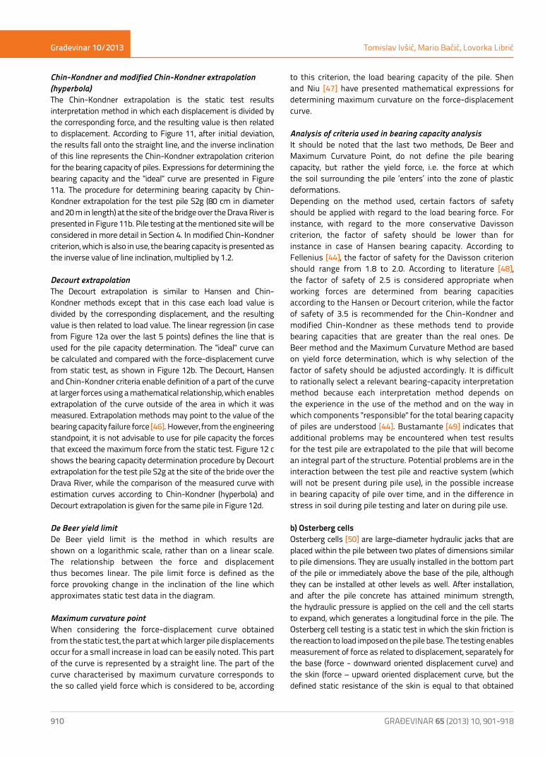
Chin-Kondner and modified Chin-Kondner extrapolation (hyperbola)The Chin-Kondner extrapolation is the static test results interpretation method in which each displacement is divided by the corresponding force, and the resulting value is then related to displacement. According to Figure 11, after initial deviation, the results fall onto the straight line, and the inverse inclination of this line represents the Chin-Kondner extrapolation criterion for the bearing capacity of piles. Expressions for determining the bearing capacity and the "ideal" curve are presented in Figure 11a. The procedure for determining bearing capacity by Chin-Kondner extrapolation for the test pile S2g (80 cm in diameter and 20 m in length) at the site of the bridge over the Drava River is presented in Figure 11b. Pile testing at the mentioned site will be considered in more detail in Section 4. In modified Chin-Kondner criterion, which is also in use, the bearing capacity is presented as the inverse value of line inclination, multiplied by 1.2.
Decourt extrapolationThe Decourt extrapolation is similar to Hansen and Chin-Kondner methods except that in this case each load value is divided by the corresponding displacement, and the resulting value is then related to load value. The linear regression (in case from Figure 12a over the last 5 points) defines the line that is used for the pile capacity determination. The "ideal" curve can be calculated and compared with the force-displacement curve from static test, as shown in Figure 12b. The Decourt, Hansen and Chin-Kondner criteria enable definition of a part of the curve at larger forces using a mathematical relationship, which enables extrapolation of the curve outside of the area in which it was measured. Extrapolation methods may point to the value of the bearing capacity failure force [46]. However, from the engineering standpoint, it is not advisable to use for pile capacity the forces that exceed the maximum force from the static test. Figure 12 c shows the bearing capacity determination procedure by Decourt extrapolation for the test pile S2g at the site of the bride over the Drava River, while the comparison of the measured curve with estimation curves according to Chin-Kondner (hyperbola) and Decourt extrapolation is given for the same pile in Figure 12d.
De Beer yield limitDe Beer yield limit is the method in which results are shown on a logarithmic scale, rather than on a linear scale. The relationship between the force and displacement thus becomes linear. The pile limit force is defined as the force provoking change in the inclination of the line which approximates static test data in the diagram.
Maximum curvature pointWhen considering the force-displacement curve obtained from the static test, the part at which larger pile displacements occur for a small increase in load can be easily noted. This part of the curve is represented by a straight line. The part of the curve characterised by maximum curvature corresponds to the so called yield force which is considered to be, according
to this criterion, the load bearing capacity of the pile. Shen and Niu [47] have presented mathematical expressions for determining maximum curvature on the force-displacement curve.
Analysis of criteria used in bearing capacity analysisIt should be noted that the last two methods, De Beer and Maximum Curvature Point, do not define the pile bearing capacity, but rather the yield force, i.e. the force at which the soil surrounding the pile ‘enters’ into the zone of plastic deformations.Depending on the method used, certain factors of safety should be applied with regard to the load bearing force. For instance, with regard to the more conservative Davisson criterion, the factor of safety should be lower than for instance in case of Hansen bearing capacity. According to Fellenius [44], the factor of safety for the Davisson criterion should range from 1.8 to 2.0. According to literature [48], the factor of safety of 2.5 is considered appropriate when working forces are determined from bearing capacities according to the Hansen or Decourt criterion, while the factor of safety of 3.5 is recommended for the Chin-Kondner and modified Chin-Kondner as these methods tend to provide bearing capacities that are greater than the real ones. De Beer method and the Maximum Curvature Method are based on yield force determination, which is why selection of the factor of safety should be adjusted accordingly. It is difficult to rationally select a relevant bearing-capacity interpretation method because each interpretation method depends on the experience in the use of the method and on the way in which components "responsible" for the total bearing capacity of piles are understood [44]. Bustamante [49] indicates that additional problems may be encountered when test results for the test pile are extrapolated to the pile that will become an integral part of the structure. Potential problems are in the interaction between the test pile and reactive system (which will not be present during pile use), in the possible increase in bearing capacity of pile over time, and in the difference in stress in soil during pile testing and later on during pile use.
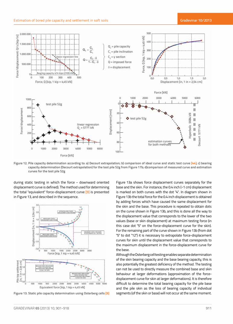
b) Osterberg cellsOsterberg cells [50] are large-diameter hydraulic jacks that are placed within the pile between two plates of dimensions similar to pile dimensions. They are usually installed in the bottom part of the pile or immediately above the base of the pile, although they can be installed at other levels as well. After installation, and after the pile concrete has attained minimum strength, the hydraulic pressure is applied on the cell and the cell starts to expand, which generates a longitudinal force in the pile. The Osterberg cell testing is a static test in which the skin friction is the reaction to load imposed on the pile base. The testing enables measurement of force as related to displacement, separately for the base (force - downward oriented displacement curve) and the skin (force – upward oriented displacement curve, but the defined static resistance of the skin is equal to that obtained
Građevinar 10/2013
911GRAĐEVINAR 65 (2013) 10, 901-918
Estimation of bored pile capacity and settlement in soft soils
Figure 13a shows force displacement curves separately for the base and the skin. For instance, the 0.4 inch (~1 cm) displacement is marked on both curves with the dot "4". In diagram shown in Figure 13b the total force for the 0.4 inch displacement is obtained by adding forces which have caused the same displacement for the skin and the base. This procedure is repeated to obtain dots on the curve shown in Figure 13b, and this is done all the way to the displacement value that corresponds to the lower of the two values (base or skin displacement) at maximum testing force (in this case dot "5" on the force-displacement curve for the skin). For the remaining part of the curve shown in Figure 13b (from dot "5" to dot "12") it is necessary to extrapolate force-displacement curves for skin until the displacement value that corresponds to the maximum displacement in the force-displacement curve for the base.Although the Osterberg cell testing enables separate determination of the skin bearing capacity and the base bearing capacity, this is also potentially the greatest deficiency of the method. The testing can not be used to directly measure the combined base and skin behaviour at larger deformations (approximation of the force-displacement curve for skin at larger deformations). It is therefore difficult to determine the total bearing capacity for the pile base and the pile skin as the loss of bearing capacity of individual segments (of the skin or base) will not occur at the same moment.
Figure 12. Pile capacity determination according to: a) Decourt extrapolation; b) comparison of ideal curve and static test curve [44]; c) bearing capacity determination (Decourt extrapolation) for the test pile S2g from Figure 17b; d)comparison of measured curve and estimation curves for the test pile S2g
Figure 13. Static pile capacity determination using Osterberg cells [9]
during static testing in which the force – downward oriented displacement curve is defined). The method used for determining the total "equivalent" force-displacement curve [9] is presented in Figure 13, and described in the sequence.

Građevinar 10/2013
912 GRAĐEVINAR 65 (2013) 10, 901-918
Tomislav Ivšić, Mario Bačić, Lovorka Librić
c) Dynamic testingThe dynamic pile testing is the method that has been in practical use for many years. Dynamic pile tests are used to estimate the static bearing capacity of piles. They are based on the principles of wave mechanics, and on acceleration and deformation results measured during the testing. The testing is conducted by generation of waves in the pile during the fall of the weight weighing from 1 to 2 percent of the desired testing force. The impact force alone must be greater that the static resistance of soil because a part of the force must overcome the dynamic resistance of soil. In order to mobilise longitudinal resistance, two to ten blows must be made per pile and, at that, the penetration per blow normally amounts to 1 - 2 mm [44]. The ASTM standard [51] is usually adopted in Croatia as the reference standard for dynamic testing.The entire procedure involving force application and measurement of relevant parameters is conducted by means of the so called Pile Driving Analyser (PDA). The static bearing capacity of pile can be estimated already during the testing using the so called Case Method. It is nevertheless recommended to use more complex analyses of dynamic tests for the static bearing capacity estimation, such as the analysis provided by the computer program CAPWAP [52] which estimates the bearing capacity along the skin and at the base of the pile. The basic concept of the program involves modelling of the pile and soil, which are defined by a set of springs and dampers, and then the model is "loaded" by the curve of measured velocity (from the testing), and its response is determined. The best possible overlap of the measured and calculated curves is defined by the iteration method (change in
the pile and soil model). Once the satisfactory curve overlapping is attained, the soil model properties and the limit bearing capacity of the tested pile are considered established.Although the dynamic testing can be used to estimate static bearing capacity, it is not able to define with sufficient accuracy the force-displacement behaviour that characterises the real behaviour of the pile under static conditions, cf. Figure 14. In addition, this testing can not be used to determine settlements resulting from long-term load. As the static bearing capacity is interpreted (rather than measured directly), a highly educated personnel is needed for correct analysis, as the modelling and parameter estimation procedure is complex and ambiguous.
d) Statnamic testingThe Statnamic testing, also known as the rapid load testing, is a dynamic pile testing method for determining the static capacity of piles. The load applied during the testing is such that the inertia and damping effects significantly influence the testing itself, and the loading is sufficiently long (up to 20 times longer compared to dynamic testing) so that the effects of wave propagation through the pile are minimum. The load force amounts to 5 - 7 % of the desired testing force. Relatively long duration of the impulse results in equal velocities at the bottom and the top of the pile, which is why the pile moves as a stiff body (i.e. it translates). This assumption is not applicable to longer piles (piles exceeding 25-30 m in length) [54]. The following values are measured during the testing: force, displacement, and pile acceleration.A good statistic correspondence of Statnamic test results with static tests was established through a series of tests, and the
Figure 14. Interpretation of results obtained by dynamic pile testing [53]
Građevinar 10/2013
913GRAĐEVINAR 65 (2013) 10, 901-918
Estimation of bored pile capacity and settlement in soft soils
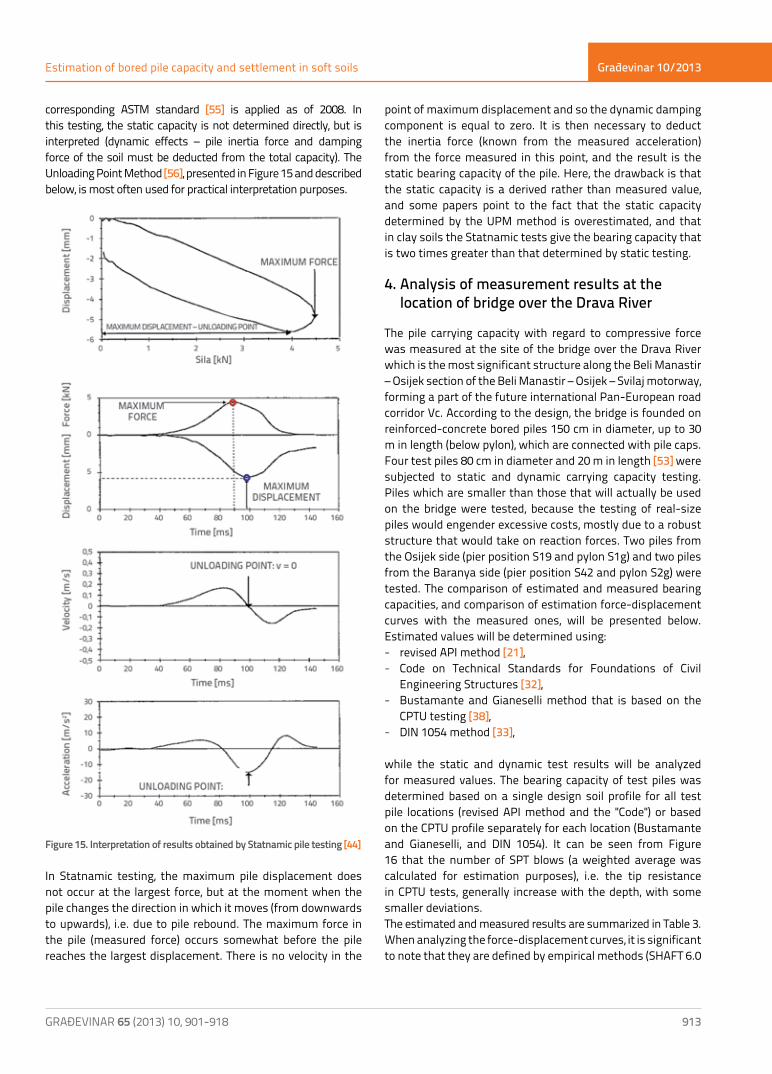
corresponding ASTM standard [55] is applied as of 2008. In this testing, the static capacity is not determined directly, but is interpreted (dynamic effects – pile inertia force and damping force of the soil must be deducted from the total capacity). The Unloading Point Method [56], presented in Figure 15 and described below, is most often used for practical interpretation purposes.
In Statnamic testing, the maximum pile displacement does not occur at the largest force, but at the moment when the pile changes the direction in which it moves (from downwards to upwards), i.e. due to pile rebound. The maximum force in the pile (measured force) occurs somewhat before the pile reaches the largest displacement. There is no velocity in the
point of maximum displacement and so the dynamic damping component is equal to zero. It is then necessary to deduct the inertia force (known from the measured acceleration) from the force measured in this point, and the result is the static bearing capacity of the pile. Here, the drawback is that the static capacity is a derived rather than measured value, and some papers point to the fact that the static capacity determined by the UPM method is overestimated, and that in clay soils the Statnamic tests give the bearing capacity that is two times greater than that determined by static testing.
4. Analysis of measurement results at the location of bridge over the Drava River
The pile carrying capacity with regard to compressive force was measured at the site of the bridge over the Drava River which is the most significant structure along the Beli Manastir – Osijek section of the Beli Manastir – Osijek – Svilaj motorway, forming a part of the future international Pan-European road corridor Vc. According to the design, the bridge is founded on reinforced-concrete bored piles 150 cm in diameter, up to 30 m in length (below pylon), which are connected with pile caps. Four test piles 80 cm in diameter and 20 m in length [53] were subjected to static and dynamic carrying capacity testing. Piles which are smaller than those that will actually be used on the bridge were tested, because the testing of real-size piles would engender excessive costs, mostly due to a robust structure that would take on reaction forces. Two piles from the Osijek side (pier position S19 and pylon S1g) and two piles from the Baranya side (pier position S42 and pylon S2g) were tested. The comparison of estimated and measured bearing capacities, and comparison of estimation force-displacement curves with the measured ones, will be presented below. Estimated values will be determined using: - revised API method [21], - Code on Technical Standards for Foundations of Civil
Engineering Structures [32], - Bustamante and Gianeselli method that is based on the
CPTU testing [38], - DIN 1054 method [33],
while the static and dynamic test results will be analyzed for measured values. The bearing capacity of test piles was determined based on a single design soil profile for all test pile locations (revised API method and the "Code") or based on the CPTU profile separately for each location (Bustamante and Gianeselli, and DIN 1054). It can be seen from Figure 16 that the number of SPT blows (a weighted average was calculated for estimation purposes), i.e. the tip resistance in CPTU tests, generally increase with the depth, with some smaller deviations.The estimated and measured results are summarized in Table 3.When analyzing the force-displacement curves, it is significant to note that they are defined by empirical methods (SHAFT 6.0
Figure 15. Interpretation of results obtained by Statnamic pile testing [44]

Građevinar 10/2013
914 GRAĐEVINAR 65 (2013) 10, 901-918
Tomislav Ivšić, Mario Bačić, Lovorka Librić
software [25] and DIN 1054 [33]), while the measured curve is the result of static bearing capacity testing. At this level of comparison, it is possible to determine, besides the bearing capacity, the settlement value for individual estimation or measurement methods, but also to analyse pile behaviour at various load levels. SHAFT is a computer software with an incorporated database of force-displacement curves, which were obtained by interpretation of static test results on a great number of test or working piles. For a given soil
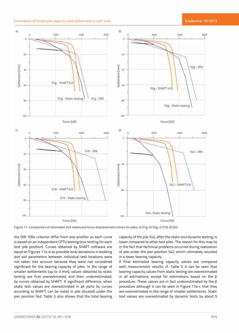
profile, the program generates a range of expected curves that is harmonized with the maximum bearing capacity as determined using the revised API method.It can be seen from Figure 17 that results obtained by static testing are usually overestimated by curves designed according to DIN 1054. In case of test piles situated under pylons S1g and S2g, this "overestimation" is practically negligible, while it is clearly distinguishable in case of test piles under piers S19 and S42. Curves obtained according to
Figure 16. Results at the site of the bridge over the Drava River: a) SPP; b) CPTU [53])
Pile position Bearing capacity[kN] Rev. API Code CPTU Bustamante &
Gianeselli DIN 1054 STATIC DINAMIC
Pier S19
Qs 3101 1072 2444 4122,8 - 3833,0
Qb 577 5444 4493 1730,8 - 940,6
Qult 3678 6366 6937 5853,6 4500 4773,6
Pylon S1g
Qs 3101 1072 1866 2940,2 - 3597,4
Qb 577 5444 3092 1646,8 - 826,8
Qult 3678 6366 4958 4587,0 4250 4424,2
Pylon Ssg
Qs 3101 1072 2082 3765,1 - 3800,1
Qb 577 5444 2927 1597,2 - 1300,0
Qult 3678 6366 5009 5362,3 4900 5100,1
Pier S42
Qs 3101 1072 2268 3620,6 - 2831,1
Qb 577 5444 3285 1529,1 - 983,8
Qult 3678 6366 5553 5149,7 3100 3814,9
Table 3. Estimated bearing capacity results for test piles in [kN]
Građevinar 10/2013
915GRAĐEVINAR 65 (2013) 10, 901-918
Estimation of bored pile capacity and settlement in soft soils
the DIN 1054 criterion differ from one another as each curve is based on an independent CPTU testing (one testing for each test pile position). Curves obtained by SHAFT software are equal on Figures 17a-d as possible local deviations in bedding and soil parameters between individual test locations were not taken into account because they were not considered significant for the bearing capacity of piles. In the range of smaller settlements (up to 3 mm), values obtained by static testing are first overestimated, and then underestimated, by curves obtained by SHAFT. A significant difference, when static test values are overestimated in all parts by curves according to SHAFT, can be noted in pile situated under the pier position S42. Table 3 also shows that the total bearing
capacity of the pile S42, after the static and dynamic testing, is lower compared to other test piles. The reason for this may lie in the fact that technical problems occurred during realization of pile under the pier position S42, which ultimately resulted in a lower bearing capacity.If final estimated bearing capacity values are compared with measurement results, cf. Table 3, it can be seen that bearing capacity values from static testing are overestimated in all estimations, except for estimations based on the b procedure. These values are in fact underestimated by the b procedure although it can be seen in Figure 17a-c that they are overestimated in the range of smaller settlements. Static test values are overestimated by dynamic tests by about 5
Figure 17. Comparison of estimated and measured force-displacement curves for piles; a) S1g; b) S2g; c) S19; d) S42

Građevinar 10/2013
916 GRAĐEVINAR 65 (2013) 10, 901-918
Tomislav Ivšić, Mario Bačić, Lovorka Librić
percent at piles S1g, S2g and S19, and by 23 percent at pile S42 (where technical problems were noted during construction). This shows that static tests can partly be replaced by dynamic tests, although not completely as only static tests can be considered relevant for creation of realistic force-displacement curves [13].
Determination of design bearing capacitiesEstimated limit capacities of piles, and measured results, are presented in Table 3. However, design or "allowed" values, in which calculated or measured values are reduced using prescribed coefficients or factors, are normally used in construction projects. Prescribed values, just like the concepts for expressing uncertainties, greatly vary in national regulations.The concept of general (global) factor of safety for the determination of the so called allowed bearing capacity of piles, based on the above presented limit values, used to be widely accepted in the estimation of bearing capacity of piles. Global factor values most frequently ranged from 2.5 to 3.5 (with various discussions about an appropriate value), while the allowed bearing capacity was compared with the non-factorized design load exerted on piles. According to the earlier regulation [32], the partial safety factor was applied for material parameters instead of the global factor.The present-day concept involving a more accurate determination and diversification of uncertainty is expressed through partial coefficients for actions and resistance values, and is included in European structural standards (Eurocodes). This concept is also increasingly recognised in other countries (e.g. American agency recommendations [9]).The design bearing capacity expressed through partial coefficients for resistance can not be directly compared with the former "allowed" carrying capacity of piles. In addition, in the European Union, each country is allowed (at least for now) to specify the design approach and partial coefficients by its national addendum, which is why uniform results will not be obtained even in this "harmonized" system.To enable comparison, design bearing capacities and partial coefficients from the Croatian national addendum to the "geotechnical" Eurocode 7 [58], for the recommended design approach 2, are presented below: - The partial coefficient for resistance γt = 1.2 and correlation
coefficients ξ3 = 1.6 (for an average value), or ξ4 = 1.5 (for the minimum value) are applied for values from table 3, for procedures that are used for direct determination of typical bearing capacity based on in situ test results; this gives design carrying capacities ranging from 2043 to 2728 kN.
- The partial factor for resistance γt = 1.2, and model factor 1.5, are applied for the procedure that alternatively determines typical values from soil parameters ("Code" – although expressions can not be recommended for practical use
due to unknown calibration basis); this gives the "design" carrying capacity of 3537 kN.
- For dynamic testing from measured results (not including pier position S42), and the individual correlation coefficient ξ5 = 1.6, the minimum design carrying capacity is 2765 kN.
- For static testing from measured results (not including pier position S42), and the individual correlation coefficient ξ5 = 1.4, the minimum design carrying capacity is 3036 kN.
The results show that the dispersion of design capacities (with respect to limit capacities from Table 3) has been somewhat reduced due to the use of different partial coefficients.
5. Conclusion
Piling techniques have been used by humans for thousands of years, and so today we have at disposal a wide range of piles, differing from each other by material used and/or by execution method. The determination of bearing capacity and settlement of piles in soft soils constitutes an ambiguous and highly challenging task for engineers, while procedures for determining relevant parameters are mostly the "mixture" of theory and empiricism.The static force – displacement curve can directly be determined only by in-situ static testing, which is then used to interpret the bearing capacity of piles, using one of many interpretation procedures. Results of other in-situ methods are interpreted in order to determine static bearing capacity but, due to some testing limitations, they can not produce a "realistic" force – displacement curve in the form in which it can be obtained by static testing.The comparison of empirical procedures and in-situ tests conducted to determine bearing capacity and settlement of bored piles in soft soils is also presented on an example of four test piles constructed at the site of the bridge over the Drava River, which is situated on the route of the future international Pan-European road corridor Vc. This example additionally confirms the significance of field tests, as results obtained by calculation methods are generally much higher that the bearing capacity values obtained by in-situ testing.Although the primary role of piles is to provide an appropriate bearing capacity, i.e. to ensure reliable building foundations, there are some additional aspects of bored pile utilisation that have not been mentioned in the paper. According to Poulos [12], these aspects include the use of piles as supporting structures for strengthening the foundation soil (micropiles), and also as drainage elements, and even in the transfer of geothermal energy, where geothermal pipes are attached to the reinforcement of bored piles, so that efficient transfer of energy is ensured [59]. Environmentally acceptable aspects of pile design include (in addition to "energy" piles) the reuse of already constructed piles, and also the design and construction of piles that can be used several times [8].

Građevinar 10/2013
917GRAĐEVINAR 65 (2013) 10, 901-918
Estimation of bored pile capacity and settlement in soft soils
REFERENCES[1] Cezar, G.J.: Zapisi o Galskom ratu, pogl.4, prijevod, Jesenski i Turk,
Zagreb, 2010.[2] Vitruvije: Deset knjiga o arhitekturi, prijevod, Golden marketing i
IGH, Zagreb, 1999.[3] Rheidt, K.: Pile Foundation in the Anatolian Mountains-Wrong
technique at the Wrong place?, 3rd International Congress on Construction History, Cottbus, pp. 1219-1226, 2009.
[4] Internet: http://www.geoforum.com/info/pileinfo/, preuzeto 07.05.2013.
[5] Van Impe, W.F.: Screw piling: still a challenging discussion topic?, IV Seminar on Deep Foundations on Bored and Auger Piles, ed. Van Impe , Millpress, Rotterdam, pp. 3-8 , 2003.
[6] O’Neill, M.W.: Side resistance in piles and drilled shafts, Journal of Geotechnical and Geoenvironmental Engineering, ASCE, 127 (1), pp.3-16, 2001.
[7] Mandolini, A., Russo, G., Viggiani, C.: Pile foundations: Experimental investigations, analysis and design, 16th Int. Conf. on Soil Mechanics and Geotechnical Engineering, Osaka, pp. 177-213, 2005.
[8] Simpson, B., Morrison, P., Yasuda, S.,Townsend, B., Gazetas, G.: State of the art report: Analysis and design, 17th Int. Conf. on Soil Mechanics and Geotechnical Engineering, Alexandria, pp. 2873-2929, 2009.
[9] FHWA-NHI-10-016: Drilled Shafts: Construction Procedures and LRFD Design Methods, U.S. Department of Transportation, 2010.
[10] Tomlison, M., Woodward, J.: Pile Design and Construction Practice, 5th ed., Taylor & Francis, 2008.
[11] Poulos, H.G.: Pile behaviour – theory and application, Géotechnique, 39 (3), pp.365-415, 1989.
[12] Poulos, H.G.: Deep foundations – Can further research assist practice?, IV Seminar on Deep Foundations on Bored and Auger Piles, ed. Van Impe , Millpress, Rotterdam, pp. 45-55, 2003.
[13] HRN EN 1997-1:2012 - Eurokod 7: Geotehničko projektiranje -- 1. dio: Opća pravila (EN 1997-1:2004+AC:2009), HZN e-Glasilo 3/2012, 164 p., 2012.
[14] Smoltczyk, U. (ed).: Geotechnical Engineering Handbook, Ernst & Sohn, 2003.
[15] Reese, L.C.: Design and construction of drilled shafts, Journal of Geotechnical Engineering Div., ASCE, 104(1), pp. 91-116, 1978.
[16] Meyerhof, G.G.: Bearing capacity and settlement of pile foundations, Journal of Geotechnical Engineering Div., ASCE,102(3), pp. 195-228, 1976.
[17] Fellenius, B.H.: Discussion of ‘‘Side Resistance in Piles and Drilled Shafts’’ by Michael W. O’Neill, Journal of Geotechnical and Geoenvironmental Engineering, ASCE, 128(5), pp.446-448, 2002.
[18] El Hakhim, A.F., Mayne, P.W.: Discussion of ‘‘Side Resistance in Piles and Drilled Shafts’’ by Michael W. O’Neill, Journal of Geotechnical and Geoenvironmental Engineering, ASCE, 128(5), pp.448-449, 2002.
[19] Moormann, C.: Contact behaviour at the interface between bored piles and subsoil, IV Seminar on Deep Foundations on Bored and Auger Piles, ed. Van Impe , Millpress, Rotterdam, pp. 163-170, 2003.
[20] Matković, I.: Određivanje nosivosti pilota pomoću statičkog penetracijskog ispitivanja, magistarski rad, Građevinski fakultet Sveučilišta u Zagrebu, 147 p., 2011.
[21] Reese, L.C., Isenhower, W.M., Wang, S.T.: Analysis and design of shallow and deep foundations, John Wiley&Sons, 2006.
[22] O’Neill, M.W., Reese, L.C.: Drilled Shafts: Construction Procedures and Design Methods, Publication No. FHWA-IF-99-025, Federal Highway Administration, Washington, D.C., 758 p., 1999.
[23] Kulhawy, F.H.: Drilled Shaft Foundations, Chapter 14 in Foundation Engineering Handbook, 2nd Ed., H.-Y. Fang, Editor, Van Nostrand Reinhold, New York, pp. 537-552, 1991.
[24] Burland, J.B.: Shaft friction of piles in clay, Ground engineering, 6(3), pp. 30-42, 1973.
[25] SHAFT, Ver 6.0: A Program for the Study of Drilled Shafts Under Axial Loads, Ensoft Inc, 2007.
[26] Rollins, K.M., Clayton, R.J., Mikesell, R.C., Blaise, B.C.: Drilled Shaft Side Friction in Soils, Journal of Geotechnical and Geoenvironmental Engineering, 131(8), pp. 987-1003, 2005.
[27] Harraz, A.M., Houston, W.N., Walsh, K.D., Perry, C.R., Houston, S.L.: Comparison of Measured and Predicted Skin Friction Values for Axially Loaded Shaft Foundations in Gravelly Soils, Advances in Deep Foundations, ASCE, 2005.
[28] Tomlinson, M.J.: Some effects of pile driving on skin friction, Proceedings of the Conference on the Behaviour of Piles, Institution of Civile Engineers, London, 1971.
[29] Cherubini, C., Vessia, G.: Reliability approach for the side resistance of piles by means of the total stress analysis (a Method), Canadian Geotechnical Journal, 44(11), pp. 1378-1390, 2007.
[30] Chen, Y.J., Kulhawy, F.H.: Undrained strength interrelationships among CIUC, UU and UC tests. Journal of Geotechnical Engineering, 119, pp. 1732–1749, 1993.
[31] Dennis, N.D., Olson, R.E.: Axial capacity of steel pipepiles in clay, Proceedings of Geotechnical Practice in Offshore Engineering, Austin, Texas. Edited by Stephen Wright. American Society of Civil Engineers, New York, pp. 370–388., 1983.
[32] Pravilnik o tehničkim normativima za temeljenje građevinskih objekata, Sl. l. SFRJ 015/1990, pp. 653-667, 1990.
[33] DIN 1054; Sicherheit im Erd- und Grundbau, Englische Fassung der DIN 1054 (Schlussmanuskript Oktober 2005), NA 005 Normenausschuss Bauwesen (NABau)
[34] Ivšić, T., Szavits-Nossan, A., Ocvirk, E.: Suvremeni praktični postupci proračuna pilota, Priopćenja 4. Savjetovanja HGD-a, Ojačanje tla i stijena, Opatija, pp. 381-390, 2006.
[35] DeRuiter, J., Beringen, F.L.: Pile foundation for large North Sea Structures, Marine Geotechnology, 3(3), pp. 267-314, 1979.
[36] Schertman, J.H.: Guidelines for cone test, perfomance and design, Federal Highway Administration, Report FHWA-TS-78209., 1978.
[37] Tumay, M.Z., Fakhroo, M.: Pile capacity in soft clays using electric QCPT data, Proceedings of a Conference on Cone Penetration Testing and Experience, St. Louis, pp. 434-455, 1981.
[38] Bustamante, M, Gianeselli, L.: Pile bearing capacity predictions by means of static penetrometer CPT, Proceedings of the 2nd European Symposium on Penetration Testing, Amsterdam, pp. 493-500, 1982.
[39] HRN EN 1997-2:2012 - Eurokod 7: Geotehničko projektiranje -- 2. dio: Istraživanje i ispitivanje temeljnoga tla (EN 1997-2:2007+AC:2010), HZN e-Glasilo 3/2012, 191 p., 2012.
Građevinar 10/2013
918 GRAĐEVINAR 65 (2013) 10, 901-918
Tomislav Ivšić, Mario Bačić, Lovorka Librić
[40] Eslami, A., Fellenius, B.H.: Pile capacity by direct CPT and CPTU methods applied to 102 cas histories, Candaian Geotechnical Journal, 34, pp. 886-904, 1997.
[41] Powell, J.J.M., Lunne, T., Frank, R.: Semi Empirical Design Procedures for axial pile capacity in clays, Proc. XV ICSMGE, Istanbul, Balkema, pp. 991-994, 2001.
[42] ASTM-D1143: Standard Test Methods for Deep Foundations Under Static Axial Compressive Load, 15 p.
[43] ISSMFE Subcommittee on Field and Laboratory Testing, Axial Pile Loading Test, Suggested Method, ASTM Journal, Vol. 8, No. 2, 1985, pp. 79-90.
[44] Fellenius, B.H.: Basics of Foundation Design, Electronic Edition, 2009., preuzeto s www.fellenius.net 25.04.2013.
[45] NeSmith, W. M., Siegel, T. C.: Shortcomings of the Davisson offset limit applied to axial compressive load tests on cast-in-place piles, Foundation Congress and Equipment Expo, Contemporary Topics in Deep Foundations, Geotechnical Special Publication No. 185, ASCE, pp. 568-574, 2009.
[46] Barbalić, I., Galjan, B., Bandić, M., Ivandić, K.: Ispitivanje probnih pilota na gradilištu putničke luke Dubrovnik, Građevinar, 57(8), pp. 693-703, 2007.
[47] Shen, B., Niu, D.: A new method for determining the yield load of piles, Proceedings of the 4th International Conference on Piling and Deep Foundations, Deep Foundation Institute, Stresa, pp. 531-534, 1991.
[48] Abdelrahman, G.E.: Prediction of Ultimate pile load test from Axial Load Tests and Penetration Tests, The Egyptian Geotechnical Journal of Soil Mech. And Found. Eng, 10, 15 p., 2002.
[49] Bustamante, M.: Auger and Bored pile construction monitoring and testing IV Seminar on Deep Foundations on Bored and Auger Piles, ed. Van Impe , Millpress, Rotterdam, pp. 27-41, 2003.
[50] Osterberg, J. O.: Recent Advances in Load Testing Driven Piles and Drilled Shafts Using the Osterberg Load Cell Method, Geotechnical Division, Illinois Section, ASCE, 79 pp., 1994.
[51] ASTM D4945-12 Standard Test Method for High-Strain Dynamic Testing of Deep Foundations, 9 p.
[52] Rausche, F., Goble, G.G. & Likings, G.: Dynamic Determination of Pile Capacity, ASCE Journal of Geotechnical Engineering, 111 (03), pp. 367-383, 1985
[53] Bolanča, K., Bačić, M., Kovačević, M.S.: Ispitivanja nosivosti pilota na mostu preko rijeke Drave, Dani prometnica 2013 - Mjerenja, ispitivanja i monitoring na prometnicama / Lakušić, Stjepan (ur.), Građevinski fakultet Sveučilišta u Zagrebu, Zavod za prometnice, pp. 195-225, 2013.
[54] Brown, D.: Evaluation of Static Capacity of Deep Foundations from Statnamic Testing, ASTM, Geotechnical Testing Journal, 17(4), pp. 403-414, 1994.
[55] ASTM D7383-10: Standard Test Methods for Axial Compressive Force Pulse (Rapid) Testing of Deep Foundations, 9 p.
[56] Middendorp, P., Bermingham, P., Kuiper, B.: Statnamic Load Testing Of Foundation Pile, Proceedings of 4th International Conference On Application Of Stress-Wave Theory To Piles,The Hague, pp. 581-588, 1992.
[57] Middendorp, P., Beck, C., Lambo, A.: Verification of Statnamic load testing with static load testing in a cohesive soil type in Germany, Proceedings of the 8th International Conference on the Application of Stress Wave Theory to Piles, IOS Press, Amsterdam, pp. 531–536, 2008.
[58] HRN EN 1997-1:2012/NA:2012, Eurokod 7: Geotehničko projektiranje — 1. dio: Opća pravila — Nacionalni dodatak, HZN eGlasilo 3/2012
[59] Kovačević, M.S., Bačić, M., Arapov, I.: Mogućnosti podzemnog inženjerstva u iskorištavanju plitke geotermalne energije, Građevinar, 64(12), pp. 1019-1028, 2012.