
ESS | Power System | 2012-05-05 | Frithiof Jensen ESS Power System Ion Source, Front-end.
10
ESS | Power System | 2012-05-05 | Frithiof Jensen Contents • Overview of distribution system • Substations and their limitations • Power quality and EMC • Grounding system
-
Upload
hugh-harris -
Category
Documents
-
view
217 -
download
4
Transcript of ESS | Power System | 2012-05-05 | Frithiof Jensen ESS Power System Ion Source, Front-end.

ESS | Power System | 2012-05-05 | Frithiof Jensen
Contents
• Overview of distribution system• Substations and their limitations• Power quality and EMC • Grounding system

ESS | Power System | 2012-05-05 | Frithiof Jensen 3
Preliminary cable route, 24 kV cables

ESS | Power System | 2012-05-05 | Frithiof Jensen
Klystron Gallery
Cryoplants and Heat Pumps
Primary substation
Central Utility Building
Instruments
Target station
LINAC Tunnel
5
Target Station
Backup PowerPlant
20 kV Primary Station 20 kV Distribution Station
SEE LNDOM MRP
140/2063 MW
140/2063 MW
Inst. Hall 1
Inst. Hall 3
Inst. Hall 2
Cryo Test Stand
Cryo LINAC
Heat recovery
Cryo Target
Target Station
TunnelN
TunnelS
RF power
Aux. Power
6.6 kV Distribution Station
Block diagram

ESS | Power System | 2012-05-05 | Frithiof Jensen
600 V6000 KVA
Substations - LINAC
600 V6000 KVA
400 V4000 KVA
400 V4000 KVA
600 V6000 KVA
20 KV“A”
20 KV“B”
20 KV“B”
20 KV“A”
X X
IONSource
Front EndRACKS
The 400 V stations supply the LINAC controls.
This supply is “separated” from the Klystron Modulators due to potential EMC issues.
ESS assumes that the Ion Source canrun from a 400 V Station.
80 m
MEBT/LEBT/LWU/couplers
RFQDTL (5)
RF PWRRF PWR
RF PWRFront End
RACKS

ESS | Power System | 2012-05-05 | Frithiof Jensen

ESS | Power System | 2012-05-05 | Frithiof Jensen
CF/ACC
“Dumb” CB’s

ESS | Power System | 2012-05-05 | Frithiof Jensen 12
What to expect?
• Nominal voltage 400, (600), 690 or 6600 V– Maximum voltage variations +/- 10 %– Typical voltage variations +/- 5 %– Backup power + 10 % / -15 %– Random step changes of 1.5% (increase and decrease) of the supply voltage
may occur due to operation of the tap-changers of the main transformers. – Infrequent voltage dips shorter than 150 ms are permitted!
• Nominal frequency 50 Hz, +/- 1 %– Maximum variations 50 Hz, +4 % / −6 %– Backup power 50 Hz ± 15 %
• Total Harmonic Distortion, THD– Maximum value 8 %, 40’th overtone inclusive– Typical value 2 %– Voltage unbalance < 2 %

ESS | Power System | 2012-05-05 | Frithiof Jensen
ESS | Power System | 2012-05-05 | Frithiof Jensen
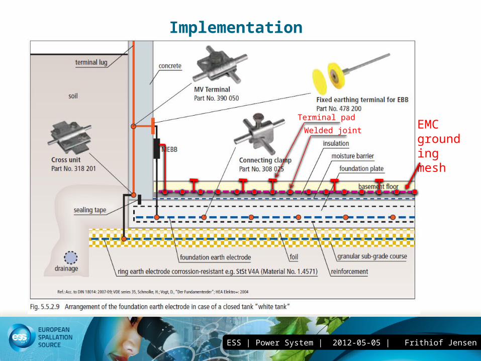
Implementation
EMC groundingmesh
Welded joint
Terminal pad

ESS | Power System | 2012-05-05 | Frithiof Jensen
questions
• Interfaces– Power quality, voltage stability needed (dips), sensitivity
to EMC/disturbances. – Is the grounding system adequate?– Power & Voltages required? Presently 400 V is
assumed, with a local LV distribution panel as the interface point.
– Where is(are) the interface(s)? ESS assumes that we have a connection point at a LV panel.
– UPS / Backup requirements? – Electrical CAD system and standardisation.


![ESS: The Machine · Main features: - One RF power source ... girder with BPMs and diagnostics box ... 2_HAKAN_DANARED-ESS-HD-Bucharest-140424.ppt [Compatibility Mode] Author:](https://static.fdocuments.net/doc/165x107/5b0e75f37f8b9af9688c05ab/ess-the-features-one-rf-power-source-girder-with-bpms-and-diagnostics-box.jpg)


