PH-ESS Power Supply Testing – The Problem
24
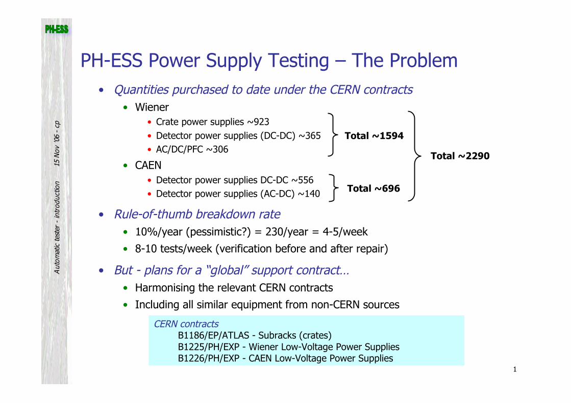
1 15 Nov '06 - cp Automatic tester - introduction • Quantities purchased to date under the CERN contracts • Wiener • Crate power supplies ~923 • Detector power supplies (DC-DC) ~365 • AC/DC/PFC ~306 • CAEN • Detector power supplies DC-DC ~556 • Detector power supplies (AC-DC) ~140 • Rule-of-thumb breakdown rate • 10%/year (pessimistic?) = 230/year = 4-5/week • 8-10 tests/week (verification before and after repair) • But - plans for a “global” support contract… • Harmonising the relevant CERN contracts • Including all similar equipment from non-CERN sources PH-ESS Power Supply Testing – The Problem CERN contracts B1186/EP/ATLAS - Subracks (crates) B1225/PH/EXP - Wiener Low-Voltage Power Supplies B1226/PH/EXP - CAEN Low-Voltage Power Supplies Total ~1594 Total ~696 Total ~2290
Transcript of PH-ESS Power Supply Testing – The Problem
1
15 N
ov '0
6 -
cpA
utom
atic
test
er -
intr
oduc
tion
• Quantities purchased to date under the CERN contracts• Wiener
• Crate power supplies ~923• Detector power supplies (DC-DC) ~365• AC/DC/PFC ~306
• CAEN• Detector power supplies DC-DC ~556• Detector power supplies (AC-DC) ~140
• Rule-of-thumb breakdown rate• 10%/year (pessimistic?) = 230/year = 4-5/week
• 8-10 tests/week (verification before and after repair)
• But - plans for a “global” support contract…• Harmonising the relevant CERN contracts
• Including all similar equipment from non-CERN sources
PH-ESS Power Supply Testing – The Problem
CERN contractsB1186/EP/ATLAS - Subracks (crates)B1225/PH/EXP - Wiener Low-Voltage Power SuppliesB1226/PH/EXP - CAEN Low-Voltage Power Supplies
Total ~1594
Total ~696
Total ~2290
LVPS Test Bench
Introduction
Brief Hardware overview.
Software overview
Reports
Description of the current set of tests
Discussion on modifications to the tests / new tests.
M. Clayton

We are building an automatic test bench for the Low Voltage Power Supplies:
● Wiener VME crate power supplies controlled by CANbus● Wiener MARATON power supplies controlled by
Ethernet● CAEN power supplies controlled by Ethernet.The object of the automatic test bench is:● To allow the tests to be performed consistently, easily and
quickly.● To allow the tests to be performed by (relatively)
unqualified personnel.● To generate reports that can be stored in a database for
future analysis.
M. Clayton

View of the test bench
This is a rather old view of the test bench, but the Lab has become a bit full of other equipment, and it is difficult to get a better picture.
M. Clayton

Of course, from behind it's hard work.The length of the wires creates problems ....
M. Clayton

Schematic view of the Test Bench
DVM
Oscilloscope
OvervoltagePS
Load
Load
Load
Load
Load
Load
Load
GPIB
Switch
Power Supply
CAN bus
Power Control
CANbus
M. Clayton

The Test Bench has the following equipment:
DVM Digital voltmeter. Controlled by GPIB.
PS Overvoltage power supply. This can inject a voltage onto a channel to test the overvoltage trip. Controlled by GPIB.
Oscilloscope For ripple measurements. Controlled by GPIB.
Power Analyser To measure the input voltage and power. Controlled by GPIB.
Power Control To vary the input voltage. Controlled by CANbus via an ELMB.
Loads Programmable loads, Agilent N3300A Controlled by GPIB.
Switch Control Agilent 3499 switch control system. Controlled by GPIB.
M. Clayton

M. Clayton

M. Clayton

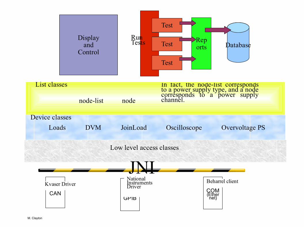
SoftwareThe software is written in Java. This object-oriented approach is very well suited to the problem. There are also various freely available libraries which have been very useful for the project.
The hardware is controlled via commercial libraries (Kvaser for the CAN bus, National Instruments for the GPIB). These libraries are available for the XP system, and are accessed from Java via the Java Native Interface. A few low-level classes allow basic access to these libraries. This fact limits the program to the XP system.
A Note on tools
Two software tools were used during this project, and they were of enormous value:
Eclipse (www.eclipse.org), a brilliant Java IDE, very fast, excellent debugging.
Netbeans (www.netbeans.org), Sun's IDE. Not as nifty as Eclipse, but brilliant at producing j2ee web sites.
M. Clayton
GPIB
National Instruments Driver
CAN
Kvaser DriverCOM(Ethernet)
Beharrel client
JNILow level access classes
Device classesLoads DVM JoinLoad Oscilloscope Overvoltage PS
List classes
node-list node
In fact, the node-list corresponds to a power supply type, and a node corresponds to a power supply channel.
Test
Test
Test Reports Database
Displayand
Control
RunTests
M. Clayton

Loading the Layout of the Test BenchWe have the classes, but must now load instances of them with the right parameters: addresses, relationships to each other.
A publicly available library called Castor (www.castor.org) allows you to do this fairly easily, although it can do nothing to reduce the sheer amount of data you have to put in.
M. Clayton

<?xml version="1.0"?><vmepstest>
<!-- Definition of the loads. Channels are numbered from left to right, looking at the front -->
<agilent name = "La" addr = "1" channel = "6" ><instrument name = "DVM" chan = "427" /><instrument name = "OSC" chan = "407" /><instrument name = "PS" chan = "507,513" />
</agilent><agilent name = "Lb" addr = "1" channel = "5" /><agilent name = "Lc" addr = "1" channel = "4" >
<instrument name = "DVM" chan = "429" /><instrument name = "OSC" chan = "409" /><instrument name = "PS" chan = "509,513" />
</agilent><agilent name = "Ld" addr = "1" channel = "3" >
<instrument name = "DVM" chan = "430" /><instrument name = "OSC" chan = "410" /><instrument name = "PS" chan = "510,513" />
</agilent>............
<dvm name = "DVM" addr = "7" />
<power-analyser name = "PA" addr = "8" />
<power-supply name = "PS" addr = "9" />
<kvaser channel = "0" /><kvaser channel = "1" />
<elmb name = "power" channel = "1" elmbaddr = "63" />
<vmeps channel = "0" />
<node-group name = "1180" switch = "103,106,108" ><node name = "5" channel = "0" pin = "1" curr = "100" >
<load>LD</load></node><node name = "12" channel = "1" pin = "10" curr = "10" >
<load>Ld</load></node><node name = "3.3" channel = "3" pin = "7" curr = "100" >
<load>LG</load><load>LH</load>
</node><node name = "-12" channel = "5" pin = "13" curr = "10" >
<load>Le</load></node><node name = "48" channel = "2" pin = "16" curr = "36" >
<load>LC</load><load>LA</load><load>LB</load><load>La</load>
</node></node-group>
</vmepstest>
M. Clayton

M. Clayton

M. Clayton

M. Clayton

M. Clayton

M. Clayton

M. Clayton

M. Clayton

Reports
As the tests run, they need to store the values they have read, and the results of the tests that they have done on them.
If we want to exploit these values in the future, we need to store them in some tagged form in a database. The variable nature of the data produced by the tests makes it difficult to map onto the tables of a relational database, but it can be easily mapped onto a XML tree. As it happens, XML can be stored in Oracle in an xmltype column, and can even be accessed from a select statement.
Libraries exist to allow you to create XML documents in Java: the simplest is jdom (www.jdom.org), and this has been used here.
Using XML turned out to be a very lucky decision, as there is a standard transformation language, xslt (http://www.w3.org/TR/xslt) which allows you to transform the xml into other forms which can be used to produce high quality reports. As this is done in Java, it can be used in a servlet to produce reports easily on the web.
There is an xml page description language xsl-fo, which can be interpreted by Apache FOP (http://xmlgraphics.apache.org/fop/).
M. Clayton

Test DOMreports
Writes data, comments and decisions
XML Database
xsl-fo
Modern browser
xhtml
screen
printer
FOP(Apache) XSLT
xsl templates
M. Clayton
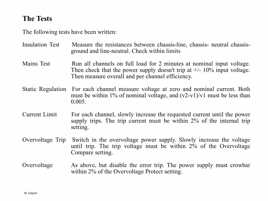
The Tests
The following tests have been written:
Insulation Test Measure the resistances between chassis-line, chassis- neutral chassis-ground and line-neutral. Check within limits
Mains Test Run all channels on full load for 2 minutes at nominal input voltage. Then check that the power supply doesn't trip at +/- 10% input voltage. Then measure overall and per channel efficiency.
Static Regulation For each channel measure voltage at zero and nominal current. Both must be within 1% of nominal voltage, and (v2-v1)/v1 must be less than 0.005.
Current Limit For each channel, slowly increase the requested current until the power supply trips. The trip current must be within 2% of the internal trip setting.
Overvoltage Trip Switch in the overvoltage power supply. Slowly increase the voltage until trip. The trip voltage must be within 2% of the Overvoltage Compare setting.
Overvoltage As above, but disable the error trip. The power supply must crowbar within 2% of the Overvoltage Protect setting.
M. Clayton

What Next?
We are trying out the test bench with as many different types of power supply as possible to get a feeling for how well it works, and see if there are any problems related to specific types.
At the moment, many power supplies fail the tests. The tests have to be reviewed.
There is a serious danger of mission creep.
Then ..Investigate control of the Maraton and later the CAEN power supplies. This will be via the Beharrell client software. There are lots of interesting things to be resolved:
● How to load the IP addresses.● How to initialise the hardware.● Etc ........
The process is slow because it takes time to understand what is going on.
M. Clayton