(ESIA) FOR AWALI-BEIRUT WATER CONVEYER PROJECT · environmental and social impact assessment (esia)...
227
ENVIRONMENTAL AND SOCIAL IMPACT ASSESSMENT (ESIA) FOR AWALI-BEIRUT WATER CONVEYER PROJECT (STUDY UPDATE) FINAL REPORT Prepared by: EARTH LINK AND ADVANCED RESOURCES DEVELOPMENT S.A.R.L. (ELARD) Submitted to: COUNCIL FOR DEVELOPMENT AND RECONSTRUCTION (CDR) Date of Submission: August 2, 2010
Transcript of (ESIA) FOR AWALI-BEIRUT WATER CONVEYER PROJECT · environmental and social impact assessment (esia)...

ENVIRONMENTAL AND SOCIAL IMPACT ASSESSMENT
(ESIA) FOR AWALI-BEIRUT WATER CONVEYER PROJECT
(STUDY UPDATE)
FINAL REPORT
Prepared by:
EARTH LINK AND ADVANCED RESOURCES DEVELOPMENT S.A.R.L.
(ELARD)
Submitted to:
COUNCIL FOR DEVELOPMENT AND RECONSTRUCTION
(CDR)
Date of Submission:
August 2, 2010

FINAL REPORT COUNCIL FOR DEVELOPMENT AND RECONSTRUCTION (CDR)
ESIA FOR AWALI-BEIRUT WATER CONVEYER PROJECT PROJECT INFORMATION
PREPARED BY ELARD ii
ELARD LEBANON
COUNCIL FOR DEVELOPMENT AND
RECONSTRUCTION DOCUMENT TYPE: Assessment Report
PROJECT REF::
ENVIRONMENTAL AND SOCIAL IMPACT ASSESSMENT NO. OF PAGES: 227
ESIA for Awali-Beirut Water Conveyer Project VERSION FINAL REPORT
APPROVED BY Ramez Kayal General Manager
REVIEWED BY Ricardo Khoury Senior Environmental Specialist
PREPARED BY
Rachad Ghanem Senior Hydrogeologist/ Project Manager
Hanadi Musharafiyeh Social Economist
Wafaa Halabi Socio-Economist
Basma Shames Geologist / Field Coordinator
Carlo Bekhazi Environmental Consultant
Ghada Chehab Environmental Expert
Rana Ghattas Quality Management Responsible
DISCLAIMER
This report has been prepared by ELARD , with all reasonable skill, care and diligence within the terms of the
contract with the client, incorporating our General Terms and Conditions of Business and taking account of the
resources devoted to it by agreement with the client. The information contained in this report is, to the best of
our knowledge, correct at the time of printing. The interpretations and recommendations are based on our
experience, using reasonable professional skill and judgment, and based upon the information that was
available to us. This report is confidential to the client and we accept no responsibility whatsoever to third parties
to whom this report, or any part thereof, is made known. Any such party relies on the report at their own risk.
ELARD
Hojeily Center 6th Fl.
Pere Yacoub Street
Sin El Fil, 2708 5803
Tel: +961 (1) 512121/2
Fax: +961 1 512123
www.elard-group.com

FINAL REPORT COUNCIL FOR DEVELOPMENT AND RECONSTRUCTION (CDR)
ESIA FOR AWALI-BEIRUT WATER CONVEYER PROJECT TABLE OF CONTENTS
PREPARED BY ELARD iii
TABLE OF CONTENTS
Table of Contents ........................................................................................................................................................ iii
List of Tables ................................................................................................................................................................ viii
List of Figures ................................................................................................................................................................ ix
Executive Summary ...................................................................................................................................................... I
Introduction ................................................................................................................................................................ I
Legal and Institutional Framework ......................................................................................................................... I
Project Description .................................................................................................................................................... I
Environmental and Social Baseline Study ........................................................................................................... III
Public Consultation ................................................................................................................................................. IX
Environemntal and Social Impact Assessment ................................................................................................... X
Environmental and Social Management Plan ................................................................................................ XIII
1. Introduction .................................................................................................................................................... 1-1
1.1 Background Information ....................................................................................................................... 1-1
1.2 General Project Description and Location ........................................................................................ 1-1
1.3 ESIA Objectives ....................................................................................................................................... 1-2
1.4 ESIA Report Structure ............................................................................................................................. 1-3
2. Legal and Institutional Framework ............................................................................................................. 2-1
2.1 Introduction ............................................................................................................................................. 2-1
2.2 Institutional Framework and Sector Organization in Lebanon ....................................................... 2-1
2.2.1 Institutional Framework for the Protection of the Environment ................................................. 2-1
2.2.2 Main Public Stakeholders concerned with the project .............................................................. 2-3
2.2.3 Ministry of Energy and Water (MoEW) ............................................................................................ 2-3
2.2.4 Ministry of Public Works and Transportation (MoPWT) ................................................................. 2-4
2.2.5 Higher Council for Urban Planning (HCUP) ................................................................................... 2-5
2.2.6 Ministry of Public Health (MoPH) ..................................................................................................... 2-5
2.2.7 Ministry of Interior and Municipalities .............................................................................................. 2-6
2.2.8 Council for Development and Reconstruction (CDR) ................................................................ 2-6
2.2.9 Beirut and Mount Lebanon Water and Wastewater Establishment (BMLWWE) ..................... 2-8
2.2.10 Litani River Authority .......................................................................................................................... 2-9

FINAL REPORT COUNCIL FOR DEVELOPMENT AND RECONSTRUCTION (CDR)
ESIA FOR AWALI-BEIRUT WATER CONVEYER PROJECT TABLE OF CONTENTS
PREPARED BY ELARD iv
2.2.11 Municipalities ....................................................................................................................................2-10
2.3 Lebanese Environmental Regulations and Standards ...................................................................2-12
2.3.1 Overview of the Legal Framework in Lebanon ..........................................................................2-12
2.3.2 Synopsis of the Legislative Framework for Environmental Protection .....................................2-13
2.3.3 EIA Draft Decree and Project Relevance to Environmental Protection Law ........................2-14
2.3.4 Relevant National Environmental Standards ..............................................................................2-15
2.3.5 Expropriation Law and Procedures ..............................................................................................2-19
2.4 International Agreements and Treaties ............................................................................................2-21
2.4.1 Relevant International Guidelines and Standards .....................................................................2-22
3. Project Description ........................................................................................................................................ 3-1
3.1 Project Components .............................................................................................................................. 3-1
3.2 Construction Aspects ............................................................................................................................. 3-7
3.2.1 Tunnels.................................................................................................................................................. 3-7
3.2.2 Ouardaniye WTW .............................................................................................................................3-13
3.2.3 Pipelines .............................................................................................................................................3-13
3.2.4 Distribution Chamber and Reservoirs ...........................................................................................3-13
3.2.5 Working Areas ...................................................................................................................................3-14
3.2.6 Access Roads ...................................................................................................................................3-14
3.3 Operational Aspects ............................................................................................................................3-14
3.3.1 Sources of Water ..............................................................................................................................3-14
3.3.2 Joun Regulation Structure ..............................................................................................................3-16
3.3.3 Tunnel and Pipelines ........................................................................................................................3-17
3.3.4 Ouardaniye WTW .............................................................................................................................3-17
3.3.5 Khalde Surge Structure ...................................................................................................................3-18
3.3.6 Khalde Flow measurement and Sampling Chamber ...............................................................3-19
3.3.7 Khalde Distribution Chamber ........................................................................................................3-19
3.3.8 Hadath 90 and 125 and Hazmieh 90 Reservoirs .........................................................................3-19
3.4 Water Quality and Treatment Process ..............................................................................................3-19
3.4.1 Raw Water Quality ...........................................................................................................................3-19
3.4.2 Treated Water Quality .....................................................................................................................3-22
3.4.3 Water Treatment Process Scheme ...............................................................................................3-25

FINAL REPORT COUNCIL FOR DEVELOPMENT AND RECONSTRUCTION (CDR)
ESIA FOR AWALI-BEIRUT WATER CONVEYER PROJECT TABLE OF CONTENTS
PREPARED BY ELARD v
4. Analysis of Alternatives ................................................................................................................................. 4-1
4.1 Introduction ............................................................................................................................................. 4-1
4.2 No Project Option ................................................................................................................................... 4-1
4.3 Formulation of Options .......................................................................................................................... 4-1
4.3.1 Constraints ........................................................................................................................................... 4-1
4.3.2 Water Transmission Options .............................................................................................................. 4-2
4.3.3 Water Treatment Options ................................................................................................................. 4-2
4.4 Detailed Evaluation ................................................................................................................................ 4-3
4.4.1 Location of Treatment Plant ............................................................................................................ 4-3
4.4.2 Means of Transmission ....................................................................................................................... 4-4
4.4.3 Water Treatment Process ................................................................................................................. 4-8
4.4.4 Cost ....................................................................................................................................................4-10
4.4.5 Security ..............................................................................................................................................4-11
4.4.6 Maintenance ....................................................................................................................................4-11
4.4.7 Operational Flexibility ......................................................................................................................4-11
4.4.8 Environmental Impact .....................................................................................................................4-11
4.5 Selection of Preferred Option ............................................................................................................4-11
5. Environmental and social Baseline ............................................................................................................. 5-1
5.1 Introduction ............................................................................................................................................. 5-1
5.2 Climate and Air Quality ......................................................................................................................... 5-1
5.3 Ambient Noise Level .............................................................................................................................. 5-1
5.3.1 Data Collection .................................................................................................................................. 5-1
5.3.2 Results ................................................................................................................................................... 5-3
5.3.3 Discussion............................................................................................................................................. 5-4
5.4 Geology and Soils .................................................................................................................................. 5-5
5.4.1 Stratigraphy ......................................................................................................................................... 5-5
5.4.2 Structure............................................................................................................................................... 5-5
5.5 Water Resources ..................................................................................................................................... 5-7
5.6 Land Use and Landscape ..................................................................................................................... 5-7
5.7 Biological Environment .......................................................................................................................... 5-8
5.7.1 General Ecology ................................................................................................................................ 5-9

FINAL REPORT COUNCIL FOR DEVELOPMENT AND RECONSTRUCTION (CDR)
ESIA FOR AWALI-BEIRUT WATER CONVEYER PROJECT TABLE OF CONTENTS
PREPARED BY ELARD vi
5.7.2 Sites Description ...............................................................................................................................5-10
5.8 Cultural Heritage ..................................................................................................................................5-16
5.9 Socio Economic Environment ............................................................................................................5-16
6. Public Consultation ....................................................................................................................................... 6-1
6.1 Introduction ............................................................................................................................................. 6-1
6.2 Review of Previous Consultations ........................................................................................................ 6-1
6.3 Recent Consultations ............................................................................................................................. 6-1
6.4 Public Participation Meeting ................................................................................................................ 6-1
7. Environemental Impact Assessment ........................................................................................................7-10
7.1 Introduction ...........................................................................................................................................7-10
7.2 Methodology of Impact Evaluation ..................................................................................................7-10
7.2.1 General Approach ..........................................................................................................................7-10
7.2.2 Impact Evaluation Pre-Screening Level .......................................................................................7-11
7.2.3 Impact Evaluation Secondary Screening Level .........................................................................7-11
7.2.1 Listing of Environmental Impact Severity .....................................................................................7-13
7.3 Potential Impacts on Ambient Air Quality .......................................................................................7-14
7.3.1 Impacts from Combustion and Exhaust Emissions .....................................................................7-15
7.3.2 Impacts from Dust Generation ......................................................................................................7-17
7.4 Potential Impacts on Soil and Landscape .......................................................................................7-20
7.4.1 Impacts of Project Footprint...........................................................................................................7-21
7.4.2 Impact on Soil Quality from Blasting Operations ........................................................................7-23
7.4.3 Impacts from Solid and Liquid Waste Generation .....................................................................7-23
7.4.4 Impacts from Accidental Spills of Fuel, Oil and Chemicals ......................................................7-26
7.4.5 Spill Prevention and Response Plan ..............................................................................................7-28
7.5 Potential Impacts on Water Resources ............................................................................................7-29
7.5.1 Impacts from Construction Activities............................................................................................7-29
7.5.2 Impacts from Operational Activities .............................................................................................7-30
7.6 Potential Impacts on Biodiversity .......................................................................................................7-34
7.7 Potential Impacts on Archeology and Cultural Heritage .............................................................7-37
7.8 Potential Socio-Economic Impacts ...................................................................................................7-38
7.8.1 Impacts From Construction Phase ................................................................................................7-38

FINAL REPORT COUNCIL FOR DEVELOPMENT AND RECONSTRUCTION (CDR)
ESIA FOR AWALI-BEIRUT WATER CONVEYER PROJECT TABLE OF CONTENTS
PREPARED BY ELARD vii
7.8.2 Impacts From Operational Phase .................................................................................................7-42
7.9 Summary of the Environmental & Social Impact Assessment before and after Mitigation ....7-43
8. Environmental Management Plan ............................................................................................................. 8-1
8.1 Introduction ............................................................................................................................................. 8-1
8.2 Environmental and Social Management Plan (ESMP) .................................................................... 8-1
8.3 ESMP Implementation Plan .................................................................................................................8-12
1.3.1 Roles and responsibilities.................................................................................................................8-12
8.4 Capacity Building .................................................................................................................................8-13
1.4.1 Training Needs during Construction Phase .................................................................................8-13
1.4.2 Training Needs during Operation Phase ......................................................................................8-14
8.5 Verification & Monitoring ....................................................................................................................8-14
1.5.1 Monitoring and Inspection Plan during the Construction Phase ............................................8-14
8.5.1 Reporting ...........................................................................................................................................8-20
9. References ...................................................................................................................................................... 9-1
10. Appendices ..................................................................................................................................................10-1
Appendix A: Topographic Maps (1/20,000) .......................................................................................................10-2
Appendix B: Location Drawings ...........................................................................................................................10-3
Appendix C: Satellite Images and Photographs ..............................................................................................10-4
Appendix D: Sludge ...............................................................................................................................................10-5
Appendix E: Noise Raw Data ................................................................................................................................10-6
Appendix F: Archaeological Report ...................................................................................................................10-7
Appendix G: Social Survey Questionnaires ........................................................................................................10-8
Appendix H: Flyer ....................................................................................................................................................10-9
Appendix I: Consultations .................................................................................................................................. 10-10
Appendix J: Expropriation .................................................................................................................................. 10-11
Appendix K: CEMP Template ............................................................................................................................. 10-12
Appendix L: CDR HSE Guidelines ...................................................................................................................... 10-13
Appendix M: Map of Component 2................................................................................................................. 10-14
Appendix N: EHS Guideline Water Sanitation ................................................................................................. 10-15
Appendix O: Water Sampling Analysis Results................................................................................................ 10-16

FINAL REPORT COUNCIL FOR DEVELOPMENT AND RECONSTRUCTION (CDR)
ESIA FOR AWALI-BEIRUT WATER CONVEYER PROJECT TABLE OF CONTENTS
PREPARED BY ELARD viii
LIST OF TABLES
Table 1-1 Overall Project Options ....................................................................................................................... III
Table 1-2 Summary of Landscape and Biodiversity ........................................................................................ V
Table 1-3 Summary of Socio-Economic situation in main villages .............................................................. VII
Table 1-4 Main Public Concerns ........................................................................................................................ IX
Table 1-5 Impacts of the Project on its surrounding with no mitigation measures .................................. XI
Table 1-6 Impacts of the Project on its surrounding with mitigation measures ......................................... XII
Table 1-7 Summary of Environmental and Social Management Plan .......................................................XIII
Table 2-1 Main Public administrations and stakeholders concerned with the protection of the
environment ............................................................................................................................................................... 2-3
Table 2-2 List of Municipalities ......................................................................................................................... 2-10
Table 2-3 Summary of institution‟s main responsibilities ............................................................................. 2-12
Table 2-4 Legal Pyramid .................................................................................................................................. 2-12
Table 2-5 Summary of Legislations ................................................................................................................. 2-13
Table 2-6 Main environmental standards in Lebanon ............................................................................... 2-15
Table 2-7 Pollutants Classification.................................................................................................................. 2-15
Table 2-8 Emission Limits .................................................................................................................................. 2-16
Table 2-9 Water pollutants .............................................................................................................................. 2-17
Table 2-10 Maximum Allowable Noise Levels ........................................................................................... 2-18
Table 2-11 Permissible Noise Exposure Standards .................................................................................... 2-18
Table 2-12 Ratified or Signed International Agreements ....................................................................... 2-21
Table 2-13 WB/IFC safeguard policies that are applicable to the project ......................................... 2-22
Table 3-1. The Awali-Beirut Water Conveyor Sub-Components ............................................................. 3-2
Table 3-2. Description of Reservoirs ............................................................................................................. 3-6
Table 3-3. Description of Pumping Stations ................................................................................................ 3-6
Table 3-4 Estimated Spoil Generation .......................................................................................................... 3-10
Table 3-5 Description of New Access Roads ............................................................................................... 3-14
Table 3-6 Hydroelectric Power Plant Chracteristics ................................................................................... 3-15
Table 3-7 Key Factors Determining the Source of Water .......................................................................... 3-16
Table 3-8 Ouardaniye WTW –Mean Operational Inputs and Vehicular Movements .......................... 3-17
Table 3-9 Ouardaniye WTW –Mean Operational Outputs and Vehicular Movements ....................... 3-18
Table 3-10 Raw Water Quality ..................................................................................................................... 3-21
Table 3-11 Water Quality Analysis (1994 and 1995) ................................................................................. 3-22
Table 3-12 Drinking Water Standards ......................................................................................................... 3-24
Table 3-13 Proposed Specifications of Cascade Aeration System ..................................................... 3-29
Table 3-14 Proposed Specification for Pre-oxidation and Disinfection. ............................................... 3-31
Table 3-15 Proposed Specifications for Coagulation .............................................................................. 3-32
Table 3-16 Proposed Specifications for Flocculation .............................................................................. 3-33
Table 3-17 Proposed Specifications for Sedimentation .......................................................................... 3-34

FINAL REPORT COUNCIL FOR DEVELOPMENT AND RECONSTRUCTION (CDR)
ESIA FOR AWALI-BEIRUT WATER CONVEYER PROJECT TABLE OF CONTENTS
PREPARED BY ELARD ix
Table 3-18 Proposed Specifications for Filtration ...................................................................................... 3-35
Table 3-19 Chemical Storage ...................................................................................................................... 3-37
Table 3-20 Sludge Yield ................................................................................................................................. 3-39
Table 3-21 Conceptual Design Parameters of Sludge Treatment Units ............................................... 3-40
Table 4-1 Characteristics of the four proposed WTW sites .......................................................................... 4-3
Table 4-2 Ranking of Treatment Processes .................................................................................................... 4-8
Table 4-3 Sludge Disposal Alternatives ........................................................................................................... 4-9
Table 4-4 Overall Project Options .................................................................................................................. 4-10
Table 5-1 Noise Level Monitoring Locations and Methodology ................................................................ 5-2
Table 5-2 National Maximum allowable noise levels and permissible occupational Noise Exposure
standards according to MoE Decision 52/1 of 1996. ......................................................................................... 5-4
Table 5-3 Rapid Ecological Assessment Sites ................................................................................................ 5-9
Table 5-4 Villages, towns and surface structures ........................................................................................ 5-18
Table 5-5 Villages and towns crossed by the tunnel .................................................................................. 5-19
Table 5-6 Demographic and socio-economic characteristics of communities in Mount Lebanon . 5-20
Table 5-7 General features of surveyed towns and villages .................................................................... 5-28
Table 5-8 Main establishments in the study area ........................................................................................ 5-33
Table 6-1 The main raised concerns ............................................................................................................... 6-2
Table 6-2 Questions Raised during Second Public Participation ............................................................... 6-3
Table 7-1 Secondary Screening Consequence Level Criteria ................................................................. 7-12
Table 7-2 Likelihood Evaluation Criteria ....................................................................................................... 7-13
Table 7-3 Impact Assessment Severity Matrix ............................................................................................. 7-13
Table 7-4 Environmental and Health Impacts of Major Air Pollutants from Combustion Sources .... 7-16
Table 7-5 Potential Negative Impacts on Biodiversity ............................................................................... 7-34
Table 7-6 Typical Sound Pressure Levels Reported from Construction Equipment (BS5228:1997) ..... 7-39
Table 7-7 Environmental Impact Assessment without mitigation measures .......................................... 7-44
Table 7-8 Environmental Impact Assement with mitigated measures ................................................................... 7-45
Table 8-1 Environmental and Social Management Plan (ESMP) ............................................................... 8-2
Table 8-2 EMP Implementation Plan ............................................................................................................. 8-12
Table 8-3 Construction and Operation Monitoring Plan ........................................................................... 8-16
Table 8-4 Water Quality Monitoring Plan during Operation Phase ......................................................... 8-19
LIST OF FIGURES
Figure 2-1 Expropriation Procedures .......................................................................................................... 2-20
Figure 3-1 Geographic location of project components ....................................................................... 3-5
Figure 3-2 Hydraulic Profile ............................................................................................................................ 3-9
Figure 3-3 Cross-Section Joun-Ouardaniye Tunnel .................................................................................. 3-11
Figure 3-4 Cross-Section Ouardaniye-Khalde Tunnel ............................................................................. 3-12
Figure 3-5 Schematic Drawing of Water Resources ............................................................................... 3-16

FINAL REPORT COUNCIL FOR DEVELOPMENT AND RECONSTRUCTION (CDR)
ESIA FOR AWALI-BEIRUT WATER CONVEYER PROJECT TABLE OF CONTENTS
PREPARED BY ELARD x
Figure 3-6 Proposed Treatment Process (Option1) ................................................................................. 3-27
Figure 3-7 Proposed treatment Process (Option2) ...................................................................................... 3-28
Figure 4-1 Altenartive Scheme Options ...................................................................................................... 4-7
Figure 5-1 Noise measurements at the Khalde distribution and connection chambers ................... 5-3
Figure 5-2 Geological Map (Source, Duberet 1955, 1/200,000) .............................................................. 5-6

FINAL REPORT COUNCIL FOR DEVELOPMENT AND RECONSTRUCTION (CDR)
ESIA FOR AWALI-BEIRUT WATER CONVEYER PROJECT TABLE OF CONTENTS
PREPARED BY ELARD xi
LIST OF ACRONYMS
ALARP As low as reasonably practicable
BMLWWE Beirut and Mount Lebanon Water and Wastewater Establishment
BPEO Best Practicable Environmental Options
BTEX Benzene Toluene Ethyl Benzene Xylene
CAW Combined Air and Water Backwash
CDR Council for Reconstruction and Development
CEMP Construction Environmental Management Plan
CESMP Construction Phase Environmental and Social Management Plan
CoM Council of Ministers
CZM Coastal Zone Management
DGA Directorate General of Antiquities
DGUP Directorate General of Urban Planning
EA Environmental Assessment
EHS Environmental Health and Safety
EIA Environmental Impact Assessment
EISM Environmental Impact Severity Matrix
ELARD Earth link and Advanced Resources Development
EMP Environmental Management Plan
ES & SR Environmental Safety and Social Representative
ESIA Environmental and Social Impact Assessment
ESM Environmental and Social Manager
ESMP Environmental and Social Management Plan
HCUP Higher Council of Urban Planning
HEP Hydro Electric Power plant
IEE Initial Environmental Examination
IFC International Finance Corporation
LRA Litani River Authority
MHER Ministry of Hydraulic and Electric Resources
MoA Ministry of Agriculture
MoC Ministry of Culture
MoE Ministry of Environment
MoEW Ministry of Energy and Water
MoI Ministry of Interior

FINAL REPORT COUNCIL FOR DEVELOPMENT AND RECONSTRUCTION (CDR)
ESIA FOR AWALI-BEIRUT WATER CONVEYER PROJECT TABLE OF CONTENTS
PREPARED BY ELARD xii
LIST OF ACRONYMS
MoIMPH Ministry of Public Healthof Interior and Municipalities
MoPH Ministry of Public Health
MoPWT Ministry of Public Works and Transportation
MSDS Material Safety Data Sheets
NGO Non Governmental Organization
NSEQ National Standards for Environmental Quality
ODS Ozone Depleting Substances
OESMP Operation Environmental and Social Management Plan
OP/BP Operational Policy / Bank Procedures
OSHA Occupational Safety and Health Administration
PAD Project Appraisal Documents
PAH Poly Aromatic Hydrocarbons
PM Particulate Matter
PMU Project Management Unit
PPE Personal Protective Equipment
PWWE Public Water and Wastewater Establishment
QA/QC Quality Assurance / Quality Control
RAP Resettlement Action Plan
TBM Tunnel Boring Machine
TMP Traffic Management Plan
TOR Terms of References
VEC Valuable Ecosystem Component
VOC Volatile Organic Compounds
WB World Bank
WHO World Health Organization
WTW Water Treatment Works
WWTP Wastewater Treatment Plants

FINAL REPORT COUNCIL FOR DEVELOPMENT AND RECONSTRUCTION (CDR)
ESIA FOR AWALI-BEIRUT WATER CONVEYER PROJECT EXECUTIVE SUMMARY
PREPARED BY ELARD I
EXECUTIVE SUMMARY
INTRODUCTION
Greater Beirut has been facing a deficit in potable water for the past forty years. Shortage in water is
estimated today at 145,000 m3/d and 275,000 m3/day for the wet and dry season respectively.
In 1970 the Lebanese Government of the day passed a decree (Presidential Decree No. 14522, May
1970) in which it allocated water from the Litani and Awali river catchments to different regions in
Lebanon.
The proposed Beirut-Awali Project will secure a sustainable source of potable water to Greater Beirut to
overcome the existing deficit and meet the city's potable water requirements on the short and medium
term.
The CDR has initiated the Project following the request of the Ministry of Energy and Water (MoEW) and
is seeking to secure financing of the project from the World Bank (WB) whereas the Beirut and Mount
Lebanon Water and Wastewater Establishment (BMLWWE) will be covering the local counterpart
financing needs.
The Project will be implemented on conventional contract basis with expected construction duration of
four years and one year operational maintenance.
The Project has a World Bank (WB) “Category A” status and therefore a full Environmental and Social
Impact Assessment (ESIA) has been required.
This report provides an updated ESIA which identifies potential environmental and social impacts
associated with the proposed Project and proposes relevant mitigation measure and management
plan.
LEGAL AND INSTITUTIONAL FRAMEWORK
This ESIA complies with the Lebanese Legislative requirements as well as with that international (WB/IFC)
and European Union standards.
The overall control of water supply and quality is under the Beirut and Mount Lebanon Water and
Wastewater Establishment acting under the Ministry of Energy and Water (MoEW) while the Ministry of
Environment and various line Ministries are charged with specific regulatory duties.
Regionally the Project area is under the Governorate of Mount Lebanon and its subordinate cazas and
Municipalities
PROJECT DESCRIPTION
The Project is divided into two main components:
1. The Awali-Beirut Water Conveyor
2. Improvement and rehabilitation of the water distribution network in Beirut and its suburbs
The Awali- Beirut Water Conveyor includes the following sub-components:
Joun Regulation Structure: set into the hillside by the existing adit access from the Joun tunnel
to the hydro-electric power station.

FINAL REPORT COUNCIL FOR DEVELOPMENT AND RECONSTRUCTION (CDR)
ESIA FOR AWALI-BEIRUT WATER CONVEYER PROJECT EXECUTIVE SUMMARY
PREPARED BY ELARD II
Joun to Ourdaniye Tunnel: running underground throughout its length of 4.1 Km.
Wadi Abou Yabes washout: (discharge point) for emergency discharge or routine
maintenance
Ourdaniye Water Treatment Works: including tunnel inlet and outlet portals and the water
treatment works. Sludge treatment and disposal facilities will be associated with this works. A
washout will be provided for emergency discharge.
Ourdaniye to Khalde tunnel: underground throughout its length of 19.7 km.
Inverted Siphon: in the Damour river with ventilation shafts at the hills to the south and north of
the valley. A washout will be provided for use in emergencies and for maintenance.
A surge shaft in the hillside above Khalde: 2,800 mm diameter shaft in reinforced concrete with
surface venting structure 7 m diameter in reinforced concrete, including improved access
road.
Outlet portal in the hillside above Khalde: termination structure in reinforced concrete and
upgraded access road
Flow measurement and sampling chamber on the hillside above Khalde.
Twin Pipeline from Khalde portal to Khalde distribution chamber: 1.9 km long and 1,400 mm
diameter
Khalde distribution and connection chamber: in reinforced concrete containing isolating and
regulating valves. Provides washout to local stream.
Twin Pipeline form Khalde distribution chamber to Hadath 90 and 125 reservoirs: 7.6 km long,
1,400mm diameter pipelines in ductile iron with connections to Hadath 90 and 125 reservoirs
and local supply.
Hadath 125 reservoir: Storage reservoir, two compartments, effective volume 30,000 m3 in
reinforced concrete with isolating valves and small surface kiosk, including access road.
Connection to local distribution system.
Hatdath 90 reservoir: Storage reservoir, two compartments, effective volume 50,000 m3 in
reinforced concrete with isolating valves and small surface kiosk, including access road.
Connection to local distribution system.
Pipeline from Hadath reservoirs to Hazmieh reservoir: 2.7 km long twin 1,300 diameter pipelines
in ductile iron, with option for further extension for supply of treated water to Beirut.
Hazmieh 90 reservoir: Storage reservoir, two compartments, effective volume 20,000 m3 in
reinforced concrete with isolating valves and small surface kiosk, including access road.
Connection to local distribution system.
Component 2 will comprise:
The construction of 16 reservoirs (between 500 m3 and 1000 m3 storage capacity each) and
associated pumping stations distributed across the various distribution zones in the project
area;
The replacement and/or installation of approximately 187 km of distribution network across the
project area in Ein El Delbi, Southern Beirut and parts of the Metn area;
Installation of 200,000 household meters in portions of the project area to be selected by the
GBMLWWE and to operate on a volumetric tariff basis;
Installation of bulk meters at the reservoirs and distribution chambers;

FINAL REPORT COUNCIL FOR DEVELOPMENT AND RECONSTRUCTION (CDR)
ESIA FOR AWALI-BEIRUT WATER CONVEYER PROJECT EXECUTIVE SUMMARY
PREPARED BY ELARD III
Analysis of Alternative
The No Project Option and other scheme alternatives were addressed in this report.
The No Project alternative is considered to be not viable, as it would have severe environmental and
socio-economic impacts in Beirut.
Five overall project options were identified and are illustrated in Table 1-1 below:
Table 1-1 Overall Project Options
OPTION OPTION NAME DESCRIPTION
1 Tunnel 1 Tunnel form Joun direct to a WTW at Khalde with pipeline transfer to
reservoirs in Beirut
2 Tunnel 2 Tunnel form Joun direct to Khalde via a WTW in Ouardaniye, with
pipeline transfer to reservoirs
3 Concrete Pipeline Tunnel from Joun to a WTW at Ouardaniye thence by concrete
pipeline to Khalde with pipeline transfer to reservoirs in Beirut
4 Ductile Iron Pipeline Tunnel from Joun to a WTW at Ouardaniye thence by ductile iron
pipeline to Khalde with pipeline transfer to reservoirs in Beirut
5 Steel Pipeline Tunnel from Joun to a WTW at Ouardaniye thence by steel pipeline to
Khalde with pipeline transfer to reservoirs in Beirut
Option 2, Tunnel 2 was preferred for the following reasons:
Lowest overall cost
Greatest security in terms of:
Least vulnerability to deliberate damage
Best resistance to earthquakes
Least risk of leakage and consequential damage
Greatest durability and design life
Lowest maintenance requirements (and thus minimized supply disruption)
Easier to supply the coastal strip from Ouardaniye WTW rather than a Khalde WTW
Spare hydraulic capacity available:
To supplement inadequate reservoir capacity in Beirut
To allow for future expansion of required; and
Least environmental impact during construction
ENVIRONMENTAL AND SOCIAL BASELINE STUDY
This section sheds light on the existing physical environment and socio-economic status.
The Climate conditions in the project area are those of a typical eastern Mediterranean climate; the
rainfall is low and restricted to the period between November and March, and the temperatures are
high in summer, but the area is not subject to the cold winter that occurs in Lebanese mountains.
The existing ambient noise levels recorded near most of the surface structure components averaged
between 60 and 65 dB (A). Therefore ambient noise levels already exceed allowed noise levels as per
Lebanese legislation (Decision 52/1 of 1996).

FINAL REPORT COUNCIL FOR DEVELOPMENT AND RECONSTRUCTION (CDR)
ESIA FOR AWALI-BEIRUT WATER CONVEYER PROJECT EXECUTIVE SUMMARY
PREPARED BY ELARD IV
The tunnel passes mainly through the upper and the middle Sannine-Maameltein Formation of
Cenomanin and Turonian ages respectively. This formation is mainly composed of hard massive
limestone and dolomitic limestone rocks. Exposures of this formation cover most of the study area with a
total thickness of around 800 m. Only the upper part of this formation is exposed in the study area.
Conformably overlying this formation is the Chekka Formation of Senonian age. It is mainly composed
of thinly bedded soft marl and marly limestone rocks. It is mostly exposed in the areas surrounding Joun
village.
Structurally the area is located few kilometers west of the Coastal Flexure which is the possible extension
of the Roum Fault (Nemer, 1999). The flexure extends from Chhim in the southern part to Baawerta and
Aaramoun in the central and northern parts of the study area respectively. The Flexure has steeply
dipping beds which gentles as we approach the study area. The general inclination of the beds in the
study area is around 20˚ dipping towards the west.
The Sannine-Maameltein Formation is the major coastal aquifer in the study area. It is karstic in nature
with tertiary porosity meaning that groundwater is flowing mainly in fissures, fractures and conduits.
There are no permanent springs issuing from this formation except close to the coastal area and mainly
below sea level in the form of submarine springs (Feasibility Report, 1994).
The position of the water table is closely related to the base level which is the sea level and it gently
rises inland with a mean gradient of 11.5 m/km. The depth of the water table was determined from
groundwater wells (Feasibility Report, 1994).
The raw water will be delivered to the plant by the use of tunnels that belong to the existing
hydroelectric system. There are two main sources of water:
1. Karaoun Lake;
2. Awali River.
Raw water quality has been analyzed several times in the past with the first one being in 1968/1972, the
second one in August 1984 and the third one in 1994/1995. The most recent water quality analysis was
conducted in 2001. The first two can be considered outdated as it is suspected that the condition and
status of the tunnels, hydroelectric power plant and dams may have changed during the proceeding
period. The analysis conducted in 1994/1995 contained some information on the most important
parameters; however the feasibility report and the preliminary design report of Montgomery Watson did
not cover comprehensive water quality information on a seasonal basis for both the Karaoun and Awali
sources. It is not possible to immediately verify the conclusions and assumptions which were the basis of
the 1994 feasibility study or the subsequent preliminary design. This is due to lack of recent detailed
water quality monitoring data at the points of concern to this project, and the fact that new data
would need to be collected over long periods to capture seasonal variations.
The landscape along the areas of the Awali project varies between the hills and the coastal planes. A
summary of nature of landscape and existing biodiversity is given in Table 1-2 below

FINAL REPORT COUNCIL FOR DEVELOPMENT AND RECONSTRUCTION (CDR)
ESIA FOR AWALI-BEIRUT WATER CONVEYER PROJECT EXECUTIVE SUMMARY
PREPARED BY ELARD V
Table 1-2 Summary of Landscape and Biodiversity
STRUCTURE LANDSCAPE BIODIVERSITY
Joun flow regulation Relatively steep valley (degraded site) very common species including
Calicotome villosa (Vahl) Link,
Poterium spinosum L., Phlomis viscosa
Poir., Nerium oleander L., Inula
viscosa (L.) Aiton, Echinops viscosus
DC. and Notobasis syriaca (L.) Cass.
Wadi Abou Yabes
Washout
Isolated hillside location Significantly degraded environment
Ouardaniye WTW open hillside location Several species were found and
identified, including one specimen of
Rhus tripartita (Ucria) D.C. and one of
Quercus calliprinos Webb, 5 species
of orchids in large quantities and
many species of butterflies.
Nahr Damour Inverted
Siphon
Deep, narrow valley Several types of vegetation cover
composed mainly by Platanus
orientalis L. (Oriental Plane), Alnus
orientalis Decne (Oriental Alder),
Acer syriacum Boiss. et Gaill. (Syrian
Maple), Pistacia lentiscus L. (Mastic),
Pistacia palaestina Boiss. (Wild
Pistachio), Quercus sp. (Oak), Salix
acmophylla Boiss. and Salix alba L.
var. micans And. (Willow) were found.
Khalde surge shaft and
outlet
R hillside sites having a steep slope to the
west
Highly degraded and/or with no
important floral biodiversity.
Khalde flow measurement
and samplignchamber
This location is characterized by the
richness of its flora and the aged
specimens of the trees found. This
was by far the most important
ecosystem visited among the 12
selected sites. This site is on the Pinus
brutia Ten series, where the conifers
Pinus brutia Ten., Pinus halepensis Mill.
and Cupressus sempervirens L. are

FINAL REPORT COUNCIL FOR DEVELOPMENT AND RECONSTRUCTION (CDR)
ESIA FOR AWALI-BEIRUT WATER CONVEYER PROJECT EXECUTIVE SUMMARY
PREPARED BY ELARD VI
STRUCTURE LANDSCAPE BIODIVERSITY
the most abundant formation.
Distribution Chamber Between the new highway and the old
coastal road. Offshore, the coastal beach is
used for some recreational activities
Highly degraded and/or with no
important floral biodiversity.
Hadath 125 reservoir Terraced sloping valley Highly degraded and/or with no
important floral biodiversity.
Hadath 90 reservoir Waste ground Highly degraded and/or with no
important floral biodiversity.
Hazmieh 90 reservoir Flat to gently sloping ground Highly degraded and/or with no
important floral biodiversity.
Archaeological and historical interests are limited at the locations of surface features of the Project,
and no remains were uncovered during site investigations. Khalde has yielded some archaeological
finds but not directly in the project area.
A summary of social survey conducted at relevant main villages is given in Table 1-3 below:

FINAL REPORT COUNCIL FOR DEVELOPMENT AND RECONSTRUCTION (CDR)
ESIA FOR AWALI-BEIRUT WATER CONVEYER PROJECT EXECUTIVE SUMMARY
PREPARED BY ELARD VII
Table 1-3 Summary of Socio-Economic situation in main villages
VILLAGE/TOWN GENERAL
DESCRIPTION LIVELIHOOD ACTIVITIES
EDUCATION, CULTURE,
COMMUNITY & PUBLIC
INFRASTRUCTURE
WATER & WASTEWATER SERVICES OTHER
INFORMATION
Joun
Population: 7500-
8000
Altitude: 350-400 m
Surface area: 12
km2
Land ownership: 20-
30% publicly
owned, and the
remaining is
privately owned
Land use: 80% is
designated for
agricultural use
Agriculture: Olive groves; Citrus
orchards; Vegetables and Flowers in
greenhouses; the majority of
designated agricultural lands remain
uncultivated due to the lack of
irrigation water
Industry: Agro-food (Olive oil; Orange
Blossom water; Rose water; Carob
molasses); Manufacture of Nylon,
Tyres and concrete building blocks
Commerce: Small shops and garages
High literacy rate (95%)
Two public & two private
schools
Public Library
Afforestation campaigns
Sports facilities
Monastery of Saint Saviour
Archaeological features
Old stone houses
One dispensary & resident
doctors
Drinking, service and irrigation water
is supplied by the Barouk Water
Authority and distributed through a
public network
A public, municipal well supplements
the supply in addition to many
private wells in privately-owned lands
Small hillside reservoirs for rain water
harvesting
No sewage network; septic tanks are
used
A land survey is
underway
60-70 building
permits were
handed out in
the last three
years
60% of the
population are
seasonal
residents
Ouardaniye Population: 4000
Altitude: 350 m
Agriculture: Vegetable production in
greenhouses
Industry: A grain mill and building
blocks factories
Commerce: Restaurant/Café
One public & one private
school
One dispensary
Water is supplied through public
wells, at depths of 452m and 369m,
managed by the municipality, which
also manages a distribution network
Up to 150 private wells are drilled in
the village
No sewage network; septic tanks are
used
Al-Damour
Population: 30,000
Resident
population: 10,000
(due to
displacement &
emigration)
Land ownership: The
majority of lands are
privately owned
Land use: 20% are in
agricultural use
Agriculture: 100 ha of banana
plantations and vegetable
production
Commerce: Restaurants/Cafés; Small
shops and garages
Two public & three private
schools
Archaeological features
One dispensary & resident
doctors
The Damour River waters are used for
irrigation
Drinking and service water are
supplied through municipal public
wells and private wells
A sewage network is present but is
not operational; septic tanks are used
A land survey
has been
carried out
Around 30
building permits
were handed
out in the last
three years

FINAL REPORT COUNCIL FOR DEVELOPMENT AND RECONSTRUCTION (CDR)
ESIA FOR AWALI-BEIRUT WATER CONVEYER PROJECT EXECUTIVE SUMMARY
PREPARED BY ELARD VIII
Khalde
Residential and
touristic area, It is a
coastal area that is
rapidly urbanizing
with 15,000-20,000
residents.
Very little agricultural activities
A water distribution network runs
through Khaldeh and is supplied from
the Mechref village. Water pipes
have all been repaired this year.
Also, several privately drilled wells
exist in the village with a depth
ranging from 30-60 m but water is
slightly salty. A sewer network is
present and is connected to the
collector in Khaldeh.
residential and
touristic area
rapidly
urbanizing
Hadath Population: 150,000
Industry: Light industries – Elevators,
towels, tiles
Commerce: Banks & shops
Many public service institutions
Four public, 10 private & two
vocational schools; three
universities, including the largest
Lebanese University campus
Two hospitals, three
dispensaries and many resident
doctors
Water is supplied through the Ain El-
Delbeh water authority and
distributed through a municipally-
owned and managed network
A sewage network is present and
operational
Hazmieh Population: 6,500 Commerce: Over 10 banks and
numerous offices
Many public service institutions
One public & six private
schools; three universities
Two hospitals, one dispensary
and many resident doctors
Water is supplied through the Ain El-
Delbeh water authority from the
Daichouniyeh Spring and distributed
through a network
A sewage network is present and
operational

FINAL REPORT COUNCIL FOR DEVELOPMENT AND RECONSTRUCTION (CDR)
ESIA FOR AWALI-BEIRUT WATER CONVEYER PROJECT EXECUTIVE SUMMARY
PREPARED BY ELARD IX
PUBLIC CONSULTATION
Lack of consultation with the directly affected local communities in the earlier EIA report posed a
necessity to target these in the updated study in aim to ensure that adequate and timely information is
provided to them and other stakeholders, and that they are given the chance to voice their opinions
and concerns.
Based on an agreed plan with MoE‟s representatives, ELARD team has consulted potentially affected
local people and concerned Municipalities during the socio-economic survey. Project leaflets,
prepared in Arabic, were distributed during the survey. These aimed at introducing the project while
serving as an invitation to participate in a public consultation meeting.
The public participation event was held in the Lebanese University in Hadath at the Institute of Fine Arts
on the 12th of May 2010.
ELARD consultants presented the project details, potential impacts and mitigation measures in a 45-
minute presentation and opened the floor for one hour of open discussions with the attendees.
Various environmental impacts were discussed during the open session and some concerns rose up by
the attendees. The two main serious concerns raised by the public are summarized in Table 1-4 with an
explanation of how the concern is addressed by the project proponents.
Table 1-4 Main Public Concerns
CONCERN DESCRIPTION ACTION/ANSWER
Retrieval of 3m3/s of water Concerns were raised regarding type and
magnitude of impact that could potentially
affect the natural flow of water in the Awali
River section downstream the Joun HEP after
retrieval of the required amount of water for
the Conveyor Project
CDR representative pointed
out that the impact would be
negligible.
ELARD to investigate the issue
and address it in its
Environmental and Social
Impact Assessment Report
Structural impact from TBM
activity
Concerns on adverse impacts on the structural
stability of the St. Joseph Carmel School were
expressed by the chairperson since the tunnel
is passing beneath the school.
CDR to provide adequate
geotechnical reports proving
that there will be no direct
impacts resulting from the
tunnel boring activity.
A second Public Consultation covering both components of the project was held for the purpose of
disclosing the results of the ESIA study on 27 July 2010 and has targeted the same audience including all
related stakeholders as for the first consultation.

FINAL REPORT COUNCIL FOR DEVELOPMENT AND RECONSTRUCTION (CDR)
ESIA FOR AWALI-BEIRUT WATER CONVEYER PROJECT EXECUTIVE SUMMARY
PREPARED BY ELARD X
ENVIRONEMNTAL AND SOCIAL IMPACT ASSESSMENT
A summary of the
impacts of the Project on its surrounding environment assuming no mitigation measures are undertaken
is given in Table 1-5 in an Environmental Impact Severity Matrix (EISM) whereas Table 1-6 presents the
EISM of the project when control and mitigation measures are adopted.
With no mitigation measures being implemented, significant impacts would be attributed to the
following activities:
Dust generation
Construction works
Excavation and tunneling
Blasting
Solid and Liquid waster generation
Accidental fuel and chemical spills
Traffic (during construction phase)
Land Expropriation

FINAL REPORT COUNCIL FOR DEVELOPMENT AND RECONSTRUCTION (CDR)
ESIA FOR AWALI-BEIRUT WATER CONVEYER PROJECT EXECUTIVE SUMMARY
PREPARED BY ELARD XI
Table 1-5 Impacts of the Project on its surrounding with no mitigation measures
Activity / Source of the Impact
Unmitigated Impacts
Receptor
Air Q
ua
lity
Lan
dsc
ap
e
an
d S
oil
QU
ALI
TY
wa
ter
RESO
UR
CES
Bio
div
ers
ity
No
ise
Arc
he
olo
gic
al
So
cio
-
Ec
on
om
ic &
Pu
blic
he
alth
Construction Phase
C
Combustion and Exhaust Emissions 3C
3C
Dust Generation 4C
4C
Open Burning of solid waste 2A
2A
Project Footprint
2C
1A 2B
Construction works 4C
2C
2B
Excavation and tunneling works 4C 4C 4C 3C 2C 1A 2B
Blasting
4C
4C 4C
Solid and Liquid waste generation
4C
4C
Accidental Spill of Fuel, Oil and Chemicals
4B 4C
Land Expropriation
4C
Traffic
4C
4C
Operation Phase
C
Combustion and Exhaust Emissions
Open Burning of solid waste
Solid and Liquid waste generation
4C 3C
4C
Accidental Spill of Fuel, Oil and Chemicals
3C
Sludge Generation
1C
Water Pumps
3C
3C
Retrieval of 3m3/s of water upstream Joun
HEP 1C
1C
Trafffic
2B
2B
LEGEND
Consequences Likelihood Acceptability
1 - Negligible 4 – Significant A – Low Beneficial
2 - Minor 5 – Catastrophic B – Medium Negligible with minor
mitigation
3 - Moderate Beneficial C – High Minimize Impacts
Unacceptable

FINAL REPORT COUNCIL FOR DEVELOPMENT AND RECONSTRUCTION (CDR)
ESIA FOR AWALI-BEIRUT WATER CONVEYER PROJECT EXECUTIVE SUMMARY
PREPARED BY ELARD XII
Table 1-6 Impacts of the Project on its surrounding with mitigation measures
Activity / Source of the Impact
Mitigated Impacts
Receptor
Air Q
ua
lity
Lan
dsc
ap
e a
nd
So
il Q
UA
LITY
wa
ter
RESO
UR
CES
Bio
div
ers
ity
No
ise
Arc
he
olo
gic
al
So
cio
-
Ec
on
om
ic &
Pu
blic
he
alth
Construction Phase C
Combustion and Exhaust Emissions 2C
2C
Dust Generation 2C
2C
Open Burning of solid waste 2A
2A
Project Footprint
1C
1A 1B
Construction works 2C
1B 1B
Excavation and tunneling works 2C 2C 2B 2B 1B 1A 1B
Blasting
2C 2C
2B
Solid and Liquid waste generation
2A
2A
Accidental Spill of Fuel, Oil and Chemicals
2A 2B
Land Expropriation
3B
Traffic
3B
3B
Operation Phase
C
Combustion and Exhaust Emissions
Open Burning of solid waste
Solid and Liquid waste generation
2A 1C
2A
Accidental Spill of Fuel, Oil and Chemicals
1C
Sludge Generation
1C
Water Pumps
1B
1B
Retrieval of 3m3/s of water upstream Joun
HEP
1C
1C
Trafffic
1C
1C
LEGEND
Consequences Likelihood Acceptability
1 - Negligible 4 – Significant A – Low Beneficial
2 - Minor 5 – Catastrophic B – Medium Negligible with minor
mitigation
3 - Moderate Beneficial C – High Minimize Impacts
Unacceptable

FINAL REPORT COUNCIL FOR DEVELOPMENT AND RECONSTRUCTION (CDR)
ESIA FOR AWALI-BEIRUT WATER CONVEYER PROJECT EXECUTIVE SUMMARY
PREPARED BY ELARD XIII
ENVIRONMENTAL AND SOCIAL MANAGEMENT PLAN
Table 1-7 Summary of Environmental and Social Management Plan
PROJECT ACTIVITY
POTENTIAL
ENVIRONMENTAL
IMPACTS
MITIGATION MEASURES INSTITUTIONAL
RESPONSIBILITIES
(INCL. ENFORCEMENT
& COORDINATION)
COST ESTIMATE
CONSTRUCTION ENVIRONMENTAL AND SOCIAL MANAGEMENT PLAN (CESMP)
Site Clearance/
Excavation
Drilling/blasting,
pipeline
construction and
tunnel boring
works (to a lesser
extent)
Solid and liquid
waste generation
from camp
operations (such
as sanitary
facilities and
kitchen) and
pipelines pressure
testing)
Accidental
chemical / oil
spills or leaks
(from excavators
and tunnel boring
machine)
Disturbance to
land/landscape
(Land scaring from
Project Footprint)
Compromised Visual
Amenity
Contamination of soil
quality.
Limiting the land clearance area required for pipelines in the vicinity of
forested areas of Khalde; Planning and marking access routes and adopting
minimum safe operating width
Using existing tracks/ routes to reduce the size of the impacted area;
Minimizing (whenever possible) the time and space of heavy machinery use
and constructing intensive activities and using whenever possible existing
and previously disturbed land and roads to access site and avoiding off-
road driving, areas crossing wadis or that are prone to erosion;
Avoiding excessive removal of topsoil and minimizing grading and clearing
of vegetation;
Stabilization of topsoil and spoil stockpiles along the pipelines previously
removed during excavation works and using it as cover material whenever
possible during backfilling and site restoration;
A preliminary project handover and restoration plan should be developed
that identifies disposal options for all equipment and materials, including
products used and wastes generated on site;
Project handover (end of Construction) should comprise the complete
closure of the labor camps including the removal of all equipments and
vehicles and other fixtures and infrastructures and covering of trenches and
restoring of all sites to original state.
Reduce the use of blasted debris as much as possible and allow backfilling
and site restoration from topsoil and spoil excavated by conventional
methods (such as drilling) and generated by the tunnel boring works;
Implementation:
Contractor.
Supervision: ESM
No cost
incurred

FINAL REPORT COUNCIL FOR DEVELOPMENT AND RECONSTRUCTION (CDR)
ESIA FOR AWALI-BEIRUT WATER CONVEYER PROJECT EXECUTIVE SUMMARY
PREPARED BY ELARD XIV
PROJECT ACTIVITY
POTENTIAL
ENVIRONMENTAL
IMPACTS
MITIGATION MEASURES INSTITUTIONAL
RESPONSIBILITIES
(INCL. ENFORCEMENT
& COORDINATION)
COST ESTIMATE
Perform a soil sampling campaign in the Project affected areas, specifically
where blasting activities took place, in order to document the soil conditions
(physic-chemical characteristics, petroleum contamination, etc.) following
the cessation of construction works
Environmental
Consultant (to be
hired by CDR)
1500
Loading and
Unloading
operations (at
construction sites
and spoil
handling facilities)
Truck
transportation
(haulage)
Operation of on-
site diesel-fuelled
generators
Increase in ambient
dust levels
(fugitive dust
emissions)
Increase in
combustion/exhaust
emissions (release of
combustion gases,
NOx, CO2,SO2, CO)
All vehicles, plant and equipment engines shall be properly maintained in
accordance with the manufacturer's instructions to maximize combustion
efficiency and minimize emissions;
Usage of vehicles/machines equipped with exhaust emission control units;
All trucks transporting material likely to generate dust should be properly
covered according to Lebanese requirements;
Maintenance and reporting of monthly fuel consumption records;
Any machinery, which is intermittent in use, should be shut off in periods of
non use or, where this is impracticable to be throttled back to a minimum;
Small combustion source emissions (with a capacity of up to 50 megawatt
hours thermal (MWth)) should adhere to the IFC emission standards for
exhaust emissions in the General EHS Guidelines and MoE Decision 8/1 of
2001, whichever stricter;
Combustion source emissions with a capacity of greater than 50 MWth
should comply with the IFC EHS Guidelines for Thermal Power;
Implement proper dust control measures. Measures will include the damping
down of dust if excavations are occurring in high winds, rig dust suppression
units and the covering piles of excavated material to prevent mobilization
(with nets or matting);
Efficient scheduling of deliveries as well as establishing and enforcing
appropriate speed limits over all paved and unpaved surfaces (< 40 km/h)
via a Traffic Management Plan (TMP) approved by the Project Proponent.
Implementation:
Contractor.
Supervision: ESM
No cost incurred

FINAL REPORT COUNCIL FOR DEVELOPMENT AND RECONSTRUCTION (CDR)
ESIA FOR AWALI-BEIRUT WATER CONVEYER PROJECT EXECUTIVE SUMMARY
PREPARED BY ELARD XV
PROJECT ACTIVITY
POTENTIAL
ENVIRONMENTAL
IMPACTS
MITIGATION MEASURES INSTITUTIONAL
RESPONSIBILITIES
(INCL. ENFORCEMENT
& COORDINATION)
COST ESTIMATE
Drilling/blasting,
pipeline
construction
Vehicular
movement and
Equipment
operation
Increase in ambient
noise level Fitting all machinery and vehicles with effective exhaust silencers;
Maintaining all machinery and vehicles in good repair and in accordance
with the manufacturer‟s instructions;
Limit the working hours when near sensitive sites (schools, health care unit,
etc.);
Proper selection of equipment for the specific tasks considering the lowest
sound power level;
Maintenance of equipment as not to create unnecessary noise owing to
mechanical problems;
Operation of equipment in a manner considerate to the ambient noise
background;
Avoidance of leaving equipment idling unnecessary;
Elimination of tonal, impulsive or low frequency noise through noise control
engineering techniques where feasible (e.g. dampers, fitting of mufflers, etc.)
Provision of alternative methods if necessary (substituting hammering actions
with hydraulics);
Provision by the Contractor of adequate buffer zone with sensitive
populations in the Project Area;
Mandatory use of noise plugs during noisy activities and
Proper communication with receptors whenever highly noisy events are
planned
Implementation:
Contractor.
Supervision: ESM
No cost incurred
Vehicular
movement &
Truck
Trips/Haulage
Traffic congestion Liaising with community and government by a dedicated resource in the
field throughout the duration of the project (i.e. establishing a complaint
register to document potential public complaints.
Clearly identify the project footprint to avoid accidents during further
development of the area particularly in the designated and construction
sites.
Having a Traffic Management Plan (TMP);
Implementation:
Contractor.
Supervision: ESM
No cost incurred

FINAL REPORT COUNCIL FOR DEVELOPMENT AND RECONSTRUCTION (CDR)
ESIA FOR AWALI-BEIRUT WATER CONVEYER PROJECT EXECUTIVE SUMMARY
PREPARED BY ELARD XVI
PROJECT ACTIVITY
POTENTIAL
ENVIRONMENTAL
IMPACTS
MITIGATION MEASURES INSTITUTIONAL
RESPONSIBILITIES
(INCL. ENFORCEMENT
& COORDINATION)
COST ESTIMATE
Allowing only certified and trained drivers to carry out transportation related
activities;
Having an Emergency Response Procedures in place; and
Having a maintenance program to all vehicles associated with construction
activities.
Fuel, Oil and
Chemical
Handling and
Storage
Contamination of
soil quality and
groundwater
resources
Storage
Where appropriate, fuel, oil and chemicals stores will be sited in specific
designated areas on site on an impervious base within a suitably contained
area;
The fuel storage facilities will have a secondary containment, such as a
berm, capable of holding the capacity of the largest container plus 10% to
accommodate rainfall;
Fresh oil and waste oil will be segregated and stored separately to prevent a
potential risk of mixing;
All storage tanks will be positioned to minimize the risks of damage by
impact; All storage tanks will be of sufficient strength and structural integrity;
No storage tank will be used for the storage of fuel, oil or chemicals unless its
material and construction are compatible with the type of materials to be
stored and storage conditions (e.g. pressure and temperature);
Drip trays will be installed underneath equipment such as diesel generators,
transformers to contain leakage. The drip trays will be maintained and kept
drained of rainwater; and
All fuel and oil will be inventoried and use recorded.
Refueling
Supervision of refueling at all times by appropriate personnel: Checks to fill
hoses, valves and nozzles for signs of wear and tear prior to operation;
Checks to tank levels prior to delivery to prevent overfilling through side glass
Implementation:
Contractor.
Supervision: ESM
No cost incurred

FINAL REPORT COUNCIL FOR DEVELOPMENT AND RECONSTRUCTION (CDR)
ESIA FOR AWALI-BEIRUT WATER CONVEYER PROJECT EXECUTIVE SUMMARY
PREPARED BY ELARD XVII
PROJECT ACTIVITY
POTENTIAL
ENVIRONMENTAL
IMPACTS
MITIGATION MEASURES INSTITUTIONAL
RESPONSIBILITIES
(INCL. ENFORCEMENT
& COORDINATION)
COST ESTIMATE
or manually by dipstick logs;
Locating fill pipes within the containment (unless shut-off valves are fitted);
Grounding of tanks and grounding of vehicles during fuel transfers; and
Ensuring a supply of suitable absorbent materials is available at re-fuelling
points for use in dealing with minor spills. If a leak or spill occurs during
loading or offloading operations, the operations will be stopped and the spill
will be contained, cleaned up and collected based on the Spill Response
Plan.
Chemicals
Personnel handling chemicals will be trained in their handling and use and
aware of the associated hazards including the personnel protective
equipment (PPE) requirements through pre-task instruction.
Material Safety Data Sheets (MSDS) for all chemicals supplied will be held at
the storage area, the point of use and by the site medical staff and site
ES&SR representative; Safety signage will be in place;
All chemical deliveries (loading and unloading operations) will be supervised
at all times and will be transferred to a secure storage area without delay;
Storage of chemicals will be sited on designated areas at the site; an
inventory of all chemicals on site will be kept and use will be recorded.
Chemicals will be properly packaged, labeled and stored;
Dangerous/hazard chemicals will be stored separately;
Chemical storage drums will be in good condition and with sealed bungs. All
used drums will be washed / flushed with water and pierced before leaving
the site to prevent local use and subsequent exposure to contaminants if
they are not able to be returned to the original supplier.
All tanks and containers will be clearly labeled with the nature of the
contents and placarded with the MSDS. The storage of chemical products in
containers or on palettes equipped with plastic dust cover against severe
weather. Chemicals will be shaded. Chemical storage drums and

FINAL REPORT COUNCIL FOR DEVELOPMENT AND RECONSTRUCTION (CDR)
ESIA FOR AWALI-BEIRUT WATER CONVEYER PROJECT EXECUTIVE SUMMARY
PREPARED BY ELARD XVIII
PROJECT ACTIVITY
POTENTIAL
ENVIRONMENTAL
IMPACTS
MITIGATION MEASURES INSTITUTIONAL
RESPONSIBILITIES
(INCL. ENFORCEMENT
& COORDINATION)
COST ESTIMATE
packaging are to be returned to the original supplier in an orderly fashion i.e.
palletized and shrink wrapped.
Waste
Management
Contamination of soil
quality and
groundwater
resources
CDR shall promote the use of a Licensed Municipal Waste Facility in
coordination with MoE.
All personnel shall be responsible for ensuring that standards of “good
housekeeping” are maintained. This will include clearance of all rubbish and
work associated debris;
Contractors to include a waste management plan as part of CEMP.
And CDR to ensure that solid waste management is included in the
contractor‟s agreement.
Implementation:
CDR/Contractor.
Supervision: ESM
No cost incurred
OPERATION ENVIRONMENTAL AND SOCIAL MANAGEMENT PLAN (OESMP)
Site clearance
/excavation
and spoil
stockpiling
activities
Accidental spills
Tunneling
activities
Contamination of
groundwater Quality
Clean up spills if any with an absorbent material such as cat litter.
Develop a contingency plan to prevent potential groundwater
contamination.
Passing water resulting from tunneling and excavation through oil separator
prior to discharge in the event that it has been contaminated with oily
residues.
Minimize the planned amount of land to be disturbed as much as possible.
Use special construction techniques in areas of steep slopes, erodible soils,
and stream crossings.
Reclaim or apply protective covering (e.g., vegetative cover) on disturbed
soils as quickly as possible.
Avoid creating excessive slopes during excavation and blasting operations
since these activities accelerate water percolation into ground.
Monitor construction near aquifer recharge areas to reduce potential
contamination of the aquifer.
Disposal of excess excavation materials in approved areas to control erosion
Implementation:
Contractor.
SUPERVISION: ESM
No cost incurred

FINAL REPORT COUNCIL FOR DEVELOPMENT AND RECONSTRUCTION (CDR)
ESIA FOR AWALI-BEIRUT WATER CONVEYER PROJECT EXECUTIVE SUMMARY
PREPARED BY ELARD XIX
PROJECT ACTIVITY
POTENTIAL
ENVIRONMENTAL
IMPACTS
MITIGATION MEASURES INSTITUTIONAL
RESPONSIBILITIES
(INCL. ENFORCEMENT
& COORDINATION)
COST ESTIMATE
and minimize leaching of hazardous materials.
Impose site-specific Best Management Practices, potentially including silt
fences, hay bales, vegetative covers, and diversions, to reduce impacts to
surface water from the deposition of sediments beyond the construction
areas.
Immediate implementation of the Oil spill response plan in case of
accidental events.
Site clearance
/Excavation
Vehicular
movement
Destruction of natural
habitat (loss of
forested areas and
few native flora
species)
Develop a detailed plants Inventory at the 3 identified sensitive sites
(Ouardaniye WTW, Nahr Damour Siphon/Washout and Khalde Flow
measurement and sampling chamber) prior and post construction activities
commencement as part of CEMP;
Developing an ecosystem rehabilitation plan to regenerate and reintroduce
some of the native species of trees (especially at the most degraded areas)
present in the studied area, therefore leading to positive impacts on
biodiversity.
Implementation:
Biodiversity expert
1200
Special effort and attention should be given to the 4 sensitive sites
Limiting vehicular transport to defined roads as to prevent unnecessary
damage to vegetation;
Preserving top soil excavated by conventional methods (such as drilling);
Avoiding introducing invasive plant species (e.g. weeds).
All affected areas must be replanted with indigenous species appropriate to
the respective sites; and
Implementation:
Contractor.
Supervision: ESM
Biodiversity expert
No cost incurred
Physical
excavation
(blasting, site
clearance,
trenching)
Demolition, alteration
of or damage to
archaeological
resources, whether
on surface or below-
ground
Prepare a brochure to help crew members recognize any discovery of
buried antiquities; and Archaeologist
500
Direct reporting to local authorities (DGA) in case of new findings during
Construction and proper documentation of historic sites.
Implementation:
Contractor.
Supervision: ESM
No cost incurred

FINAL REPORT COUNCIL FOR DEVELOPMENT AND RECONSTRUCTION (CDR)
ESIA FOR AWALI-BEIRUT WATER CONVEYER PROJECT EXECUTIVE SUMMARY
PREPARED BY ELARD XX
PROJECT ACTIVITY
POTENTIAL
ENVIRONMENTAL
IMPACTS
MITIGATION MEASURES INSTITUTIONAL
RESPONSIBILITIES
(INCL. ENFORCEMENT
& COORDINATION)
COST ESTIMATE
Land
Expropriation
Permanent and
irreversible loss of
land and some loss
of agricultural
greenhouses
(agricultural
business)
Temporary
severance /
disturbance of public
rights-of-way and
access to community
resources and
services.
Consultation with potentially affected communities prior to expropriation
procedures.
Fair and full compensation for land and other assets expropriated for the
project in the public interest as stated in the Lebanese expropriation law
(Law No. 58/1991 and its amendments (2006))..
Compensation to local farmers who lost their agricultural lands (loss of
livelihood);
Preparation of a Resettlement Action Plan (RAP) (ongoing) as per the World
Bank standards.
ESM No cost incurred
Fuel and
Chemicals
handling &
storage
Contamination of soil
quality and
groundwater
resources
Selecting appropriate locations for septic tanks installation as to avoid
leakage and contamination of groundwater.
Immediate cleaning of a spill by removing affected top soil layer by trained
employees
Continuous in-situ sampling of soil in the vicinity and underneath the spill for
potential contaminant; and
Stopping the source of spill (close valve, seal pipe, seal hole etc…);
Refueling in a designated fueling area that includes a temporary berm to
limit, if not prevent, the spread of any spill.
Implementation:
WTW operator
Supervision: During
the first year of
operation: ESM
After project
handover:
Environmental
representative from
BMLWWA
No cost incurred
Wastewater
generation
(sanitary/proce
ss)
Contamination of soil
quality and
groundwater
resources
CDR should commission local contractor for the collection of domestic
wastewater and disposal to nearest public sewerage network ( Frequency
will be based on septic tank volume)
Implementation:
Local contractor
Supervision year of
operation: ESM
After project
handover:
200 (unit cost)

FINAL REPORT COUNCIL FOR DEVELOPMENT AND RECONSTRUCTION (CDR)
ESIA FOR AWALI-BEIRUT WATER CONVEYER PROJECT EXECUTIVE SUMMARY
PREPARED BY ELARD XXI
PROJECT ACTIVITY
POTENTIAL
ENVIRONMENTAL
IMPACTS
MITIGATION MEASURES INSTITUTIONAL
RESPONSIBILITIES
(INCL. ENFORCEMENT
& COORDINATION)
COST ESTIMATE
Environmental
representative from
BMLWWA
Adopting as much as possible dry cleaning techniques to decrease resultant
wastewater, and to avoid flushing of spills to deeper soil layers.
Develop a stormwater management plan to ensure compliance with
regulations and prevent off-site migration of contaminated stormwater.
Implementation:
WTW Operator
Supervision: During
the first year of
operation: ESM
After project
handover:
Environmental
representative from
BMLWWA
No cost incurred
Leaching from
Naameh landfill
Contamination of
groundwater quality
Regular monitoring wells data inspection for the section of the tunnel lying
downstream the land fill
Giving additional consideration for the subject strip during maintenance of
the tunnel
Checking for any fissures or fractures in the tunnel wall during maintenance
During the first year
of operation: ESM
After project
handover:
Environmental
representative from
BMLWA
Sludge
handling and
disposal
Contamination of
groundwater
resources
Design considerations for sludge management include dewatering and
thickening processes prior to disposal.
Re-use of separated water at the inlet of the WTW instead of discharge of
liquid effluent to wadis. In the event of effluent discharge into the Wadi
(following sludge dewatering), the former should comply with the Lebanese
new standards for discharge into receiving water bodies (Decision No. 8/1).
Investigate the disposal of sludge cake to the Naameh landfill instead of
quarry rehabilitation. (In the latter case, potential for percolation/leaching
into groundwater).
Implementation:
WTW Operator
Supervision: During
the first year of
operation: ESM
After project
handover:
Environmental
representative from
No cost incurred

FINAL REPORT COUNCIL FOR DEVELOPMENT AND RECONSTRUCTION (CDR)
ESIA FOR AWALI-BEIRUT WATER CONVEYER PROJECT EXECUTIVE SUMMARY
PREPARED BY ELARD XXII
PROJECT ACTIVITY
POTENTIAL
ENVIRONMENTAL
IMPACTS
MITIGATION MEASURES INSTITUTIONAL
RESPONSIBILITIES
(INCL. ENFORCEMENT
& COORDINATION)
COST ESTIMATE
BMLWWA
Operation of
pumping
stations
Nuisance to noise-
sensitive receptors
Fitting all equipment and pumps with effective exhaust silencers
Proper selection of pumps for the specific task considering the lowest sound
power level; and,
Maintenance of pumping stations as not to create unnecessary noise owing
to mechanical problems
Insulating generator rooms and engines.
Implementation:
WTW Contractor
Supervision: During
the first year of
operation: ESM
After project
handover:
Environmental
representative from
BMLWWA
No cost incurred

FINAL REPORT COUNCIL FOR DEVELOPMENT AND RECONSTRUCTION (CDR)
ESIA FOR AWALI-BEIRUT WATER CONVEYER PROJECT INTRODUCTION
PREPARED BY ELARD 1-1
1. INTRODUCTION
1.1 BACKGROUND INFORMATION
Greater Beirut has been facing a deficit in potable water for the past forty years. Shortage in water is
estimated today at 145,000 m3/d and 275,000 m3/day for the wet and dry seasons, respectively.
In 1970 the Lebanese Government of the day passed a decree (Presidential Decree No. 14522, May
1970) in which it allocated water from the Litani and Awali river catchments to different regions in
Lebanon. As a result, Greater Beirut was allocated 50 million cubic meters for the dry season. This
corresponds to 250,000 m3/day (3m3/s) of water.
In 1977 the Ministry of Energy and Water (MoEW) on behalf of the Government requested from the
Council of Development and Reconstruction (CDR) to study the options for providing additional water
resources to Greater Beirut. Significant number of studies dealing with conveying water by means of a
tunnel and pipelines has been carried out.
At the beginning of 1994, CDR contracted Montgomery Watson and Engico to update the feasibility
study submitted by them in 1985 to re-evaluate options of the tunnel and pipeline for the conveyor.
Montgomery Watson and Engico completed the feasibility study in April 1995. They completed the
detailed design reports and tender documents in late 1997 and early 1998. While Montgomery Watson
and Engico were preparing the studies relating to the Awali-Beirut Conveyor, CDR based on
Government Decision 31, 7/4/1982, in coordination with the Ministry of Finance and the World Bank,
started to investigate ways of funding and executing the conveyor. A decision was made to execute
the conveyor on the basis of a contract, which would have a life span of 25 years.
Today the CDR is seeking to secure financing of the project from the World Bank whereas the Beirut
and Mount Lebanon Water and Wastewater Establishment (BMLWWE) will be covering the local
counterpart financing needs. It was finally decided to commission the project based on conventional
contracting basis with four years expected construction duration and one year operational
maintenance.
The CDR has contracted Montgomery Watson Harza to re-evaluate its latest feasibility study and has
contracted ELARD group for the purpose of updating the latest Environmental Impact Assessment (EIA)
study submitted by Montgomery Watson and Engico in 1998.
1.2 GENERAL PROJECT DESCRIPTION AND LOCATION
The project aims at securing a sustainable source of potable water to Greater Beirut to overcome the
existing deficit and meeting the city's potable water requirements on the short and medium term.
The Project encompasses the following components:
1. The construction of a transmission conveyor from the Awali River just north of Saida to Beirut
(Awali-Beirut Conveyor);
2. The construction of water supply networks within Greater Beirut area to distribute the water
supplied through the conveyor to the inhabitants of the area (Greater Beirut Water Supply
Networks).

FINAL REPORT COUNCIL FOR DEVELOPMENT AND RECONSTRUCTION (CDR)
ESIA FOR AWALI-BEIRUT WATER CONVEYER PROJECT INTRODUCTION
PREPARED BY ELARD 1-2
The Awali-Beirut Conveyor will supply, by gravity, the Greater Beirut area with approximately 250,000
m3/day (3 m3/s) during the dry season. The conveyor will meet the needs of Greater Beirut in the short
to medium terms. A detailed description of sub-components is provided in Section2.
The Greater Beirut Water Supply Networks component comprises construction of 16 reservoirs (between
500 m3 and 1000 m3 storage capacity each), replacement and/or installation of approximately 187 km
of distribution network and associated pumping stations as well as Installation of 200,000 household
meters in portions of the project area to be selected by the GBMLWWE and to operate on a volumetric
tariff basis.
Construction works are expected to be completed within four years.
1.3 ESIA OBJECTIVES
The ESIA is an important decision-making tool required by the Ministry of Environment and by the World
Bank, that ensures that the environmental hazards and effects of the Project are identified and
evaluated prior to operations, and that appropriate control measures are implemented. The main
objective of this study is to determine the potential environmental and social impacts associated with
the proposed Project.
The objectives of this ESIA study are to:
- Identify all applicable Lebanese national legislation, policies, standards and international
treaties, agreements, industry standards and guidelines and regulatory environmental
requirements for the project, etc.;
- Provide a detailed description of all Project activities and work plans to be carried out in sea
and on land.
- Describe the existing environmental baseline conditions of the Study Area covering the
physical, marine biodiversity, socio-economic, and cultural elements likely to be affected by
the proposed dredging and disposal activities and/or likely to cause adverse impacts upon the
Project, including both natural and man-made environments;
- Identify and assess the potential impacts on environmental and social resources associated
with the Project;
- Identify the nature and extent of any significant potential environmental and social impacts be
they positive (beneficial) or negative (adverse), temporary or permanent. This shall include
routine, non-routine (planned) operations and unplanned (accidental) events;
- Identify any significant cumulative or transboundary impacts of the project and recommend
appropriate actions to mitigate or minimize these impacts during the project execution;
- Identify and evaluate appropriate mitigation measures for these impacts;
- Identify any residual impacts following application of mitigation; and
- Identify, assess and specify methods, measures and standards to be included in the detailed
design, operation and handover of the Project, which are necessary to mitigate these impacts
and reduce them to acceptable levels.
The ESIA study shall ensure that:

FINAL REPORT COUNCIL FOR DEVELOPMENT AND RECONSTRUCTION (CDR)
ESIA FOR AWALI-BEIRUT WATER CONVEYER PROJECT INTRODUCTION
PREPARED BY ELARD 1-3
- The Project complies with international treaties, agreements and industrial standards and
guidelines.
- The Project under assessment complies with relevant Lebanese legislations, standards and
World Bank requirements.
- In the absence of any relevant Lebanese standards or requirements for sampling, construction
and disposal operations, the Project should be at a minimum, compatible with international
standards, such as those issued by the World Bank, IFC, OSHA,...
- Transparency in Project activities and engagement of local authorities and community
regarding its environmental, social and economical aspects.
1.4 ESIA REPORT STRUCTURE
This updated ESIA study is executed in accordance with the Lebanese Environmental Protection Law
No. 444 of 2002, the Lebanese Draft EIA Decree, as well as World Bank guidelines.
The report is structured as follows:
- Introduction;
- Legal and Institutional Framework;
- Project Description;
- Analysis of Alternatives;
- Environmental and Social Baseline;
- Public Participation;
- Environmental and Social Impacts Assessment;
- Environmental and Social Management Plan (ESMP) including mitigation, monitoring, and
institutional strengthening-capacity building and training;
- Appendices

FINAL REPORT COUNCIL FOR DEVELOPMENT AND RECONSTRUCTION (CDR)
ESIA FOR AWALI-BEIRUT WATER CONVEYER PROJECT LEGAL AND INSTITUTIONAL FRAMEWORK
PREPARED BY ELARD 2-1
2. LEGAL AND INSTITUTIONAL FRAMEWORK
2.1 INTRODUCTION
This chapter presents an overview of all environmental legislation and standards relevant to the
construction and operation of the Awali-Beirut Water Conveyor Project. This section sheds light on the
legal and institutional framework and identifies gaps and deficiencies in the national legal and
institutional system.
The objective is also to ensure compliance not only with the Lebanese environmental laws and
regulations, but also with the relevant international agreements, standards and guidelines of which
Lebanon is signatory and to observe non-statutory corporate standards and good practice guidance.
2.2 INSTITUTIONAL FRAMEWORK AND SECTOR ORGANIZATION IN LEBANON
2.2.1 Institutional Framework for the Protection of the Environment
In 1981, a state Ministry of Environment was created for the management of environmental affairs such
as the use of pesticides, deforestation and forest fires, solid waste disposal, protection of native
biodiversity, etc.
In 1993, Law 216 established the Ministry of Environment (MoE) and defined its mandates and functions.
Article 2 of this Law stipulates that the MoE should formulate a general environmental policy and
propose measures for its implementation in coordination with the concerned government
administrations. The article indicates that the MoE should protect the natural and man-made
environment in the interests of public health and welfare, and fight pollution from whatever source by
taking preventative and remedial action. The MoE is charged in particular with developing the
following aspects of environmental management:
A strategy for solid waste and wastewater treatment and disposal, through
participation in appropriate committees, conducting studies for this purpose, and
commissioning appropriate infrastructure works;
Permitting conditions for new industry, agriculture, quarrying and mining, and the
enforcement of appropriate remedial measures for establishments existing before
promulgation of this law;
Conditions and regulations for the use of public land, marine and reverie resources in
such a way as to protect the environment; and
Encouragement of private and collective initiatives that improve environmental
conditions.
Law 216 was amended twice according to Decrees 5591/94 and 667/97 so as to strengthen the Ministry
and reorganize its mission and prerogatives along four general policy principles; 1) Regionally balanced
development, 2) Protection of the environment through preventative measures, 3) Adoption of the
polluter pays principle and 4) Integration of environmental policies into other sectoral development
policies.

FINAL REPORT COUNCIL FOR DEVELOPMENT AND RECONSTRUCTION (CDR)
ESIA FOR AWALI-BEIRUT WATER CONVEYER PROJECT LEGAL AND INSTITUTIONAL FRAMEWORK
PREPARED BY ELARD 2-2
The Ministry of Environment plays also a role in Coastal Zone Management (CZM), as mandated by law
690/2005 that specified the prerogatives of the Ministry as follows:
The formulation of strategies, policies, programs, and action plans for CZM;
The development of relevant legislation, and participation in the preparation of international
treaties and protocols;
The promotion of awareness and guidance on CZM issues in the community;
The specification of environmental guidelines for:
The classification of establishments
Master plans for zoning (in cooperation with MoPWT)
The creation and exploitation of public beaches
Formulating the strategy, action plans, programs, and studies required for the integrated
management of hazardous and non-hazardous solid waste, domestic and industrial
wastewater, in addition to monitoring their implementation;
Protection of the coastal zone and of territorial waters;
Monitoring air, soil and water quality; recommending preventive and corrective measures, and
monitoring their application;
Regulating hunting and fishing activities in coordination with the MoA;
Controlling the use and disposal of chemicals;
Conducting inspection visits and stopping contraventions.
A major step was achieved when, in July 2002, a comprehensive environmental protection law – Law
444 - reflecting the policy principles mentioned above, was introduced. Law 444 sets the fundamental
principles that govern the management of the environment and the use of natural resources.
In doing so, the Ministry of Environment does not undertake its environmental management efforts in
isolation. Indeed a number of other government ministries and bodies have also environmental
responsibilities Table 2-1 lists the main stakeholders concerned with the environment.

FINAL REPORT COUNCIL FOR DEVELOPMENT AND RECONSTRUCTION (CDR)
ESIA FOR AWALI-BEIRUT WATER CONVEYER PROJECT LEGAL AND INSTITUTIONAL FRAMEWORK
PREPARED BY ELARD 2-3
Table 2-1 Main Public administrations and stakeholders concerned with the protection
of the environment
PUBLIC ADMINISTRATION PREROGATIVES
Ministry of Environment (MoE)
MoE reviews, approves or refuses Environmental Impact Assessment reports
prepared by engineering and/or consultancy firms for existing or for potential
projects
Ministry of Energy and Water
(MoEW)
MoEW monitors surface and underground water quality. It also estimates
water needs and uses in all the regions, and identifies the conditions and
systems needed for surface and underground water exploitation. It then
develops the schemes for distribution of water (drinking and irrigation).
Ministry of Public Works and
Transportation (MoPWT)
MoPWT manages, via its different directorates, roads, bridges and water
channels. Through its different directorates, it manages land and maritime
transportation as well as land use planning.
Higher Council of Urban Planning
(HCUP)
HCUP is responsible for urban and rural planning. In doing so it reviews designs
and plans of villages and towns, including zoning proposals for these areas. It
also reviews project decrees aiming at expropriation.
Ministry of Public Health (MoPH)
MoPH is responsible for safeguarding and improving public health through for
example setting allowable levels for contaminants in water, inspecting water
quality in public beaches and tourist resorts and protecting water resources,
specifically coastal underground water reservoirs.
Ministry of Interior (MoI) MoI stops all kinds of infractions and violations.
Council of Development and
Reconstruction (CDR)
CDR prepares all construction and development plans in the country. It also
suggests the economic, financial, and social policies needed for the
implementation of these plans and accordingly sets the priorities and presents
them to the CoM for approval.
Municipalities
Represent the level of local government with legal status, financial and
administrative independence, which exercises powers and responsibilities over
the territory it is granted by law.
2.2.2 Main Public Stakeholders concerned with the project
Several stakeholders play an important role in the management of natural resources and livelihood
strategies within the Project area. These stakeholders and their mandate relevant to the project are
presented in the sections below and summarized in Table 2-3:
2.2.3 Ministry of Energy and Water (MoEW)
Since its creation, the Ministry of Energy and Water handles water issues and controls water privileges.
The new law organizing the water sector – Law 221/2000 - confirmed the ministry‟s role in monitoring
surface and underground water quality, setting the standards that should be adopted in the studies

FINAL REPORT COUNCIL FOR DEVELOPMENT AND RECONSTRUCTION (CDR)
ESIA FOR AWALI-BEIRUT WATER CONVEYER PROJECT LEGAL AND INSTITUTIONAL FRAMEWORK
PREPARED BY ELARD 2-4
and execution of public investments related to water as well as identifying the conditions and systems
for surface and underground water exploitation. It also enhanced the Ministry‟s control over the water
amounts extracted from underground aquifers.
Indeed, Article 2 of this Law enumerates the competencies and missions of the Ministry of Energy and
Water as follows:
Monitoring, studying, and estimating the volume of water resources, and estimating water
needs and uses in all regions;
Monitoring the quality of surface and groundwater and establishing relevant standards;
Developing a general scheme for the allocation and distribution of drinking water and
irrigation water throughout the country; designing and continuously updating a Masterplan for
water to be submitted through the Minister to the Council of Ministers (CoM) for approval;
Designing, studying, and implementing large water projects such as dams, mountain lakes,
tunnels, diversion of riverbeds, water networks, etc., and overseeing their operation;
Protecting water resources against losses and pollution by elaborating legal texts and taking
necessary measures and action to prevent water pollution and restore its initial natural quality;
Developing standards to be adopted in the studies conducted by Water and Wastewater
Establishments, and the implementation of their works; in addition to guidelines and regulations
for the exploitation of surface and groundwater and the management of wastewater, and
standards for the protection and monitoring of water quality.
2.2.4 Ministry of Public Works and Transportation (MoPWT)
According to Decree 2872/1959 (Organization of the Ministry of Public Works and Transportation) and its
amendments, the Ministry of Public Works and Transport is composed of five directorates having each
its own prerogatives.
Of all 5 directorates, the Directorate General of Land and Maritime Transport and the Directorate
General of Urban Planning are those that are mainly and directly involved in CZM.
Indeed, the Directorate General of Land and Maritime Transport (Decree 1611/1971) is responsible for all
matters relating to land and maritime transport, the supervision of ports, marinas, and the public
maritime domain, in addition to its authority on the Organization of Railways and Public Transport.
Whereas, the Directorate General of Urban Planning (DGUP) is responsible for specifying and organizing
land use planning through zoning of regions, specifying allowed investments for different land uses, as
well as architectural constraints, and suitable conditions for ensuring the integration of projects within
their surrounding from an aesthetic, architectural, infrastructural, environmental, and socio-economic
point of view. As for actual enforcement, it is the responsibility of the local authority (municipality/
district) and the Security Forces. The DGUP interferes in the case of complaints, and plays an inspection
role upon termination of building construction by verifying the compatibility of facilities with permit
conditions and specifications.
On the other hand, the Directorate General of Roads and Buildings (Decree 13379/1998), is in charge of
the design, execution and maintenance of roads, bridges, walls, and water channels. The Directorate

FINAL REPORT COUNCIL FOR DEVELOPMENT AND RECONSTRUCTION (CDR)
ESIA FOR AWALI-BEIRUT WATER CONVEYER PROJECT LEGAL AND INSTITUTIONAL FRAMEWORK
PREPARED BY ELARD 2-5
also designs, expropriates, subcontracts and supervises works including maintenance of public
buildings and assets. The presence of a Department of Environment and Traffic Safety within the
Directorate General of Roads and Buildings should be noted, which is responsible for assessing the
environmental impact of projected roads, and recommending mitigation measures.
2.2.5 Higher Council for Urban Planning (HCUP)
The Higher Council for Urban Planning (HCUP) that was created in 1983 (decree-law 69/1983) is the
party responsible for urban and rural planning. It comprises representatives from CDR, MoIM, MoPWT,
MoE, MoC and other concerned ministries, municipalities as well as Order of Engineers and Architects. It
can meet with the concerned parties (such as municipalities and public institutions) for discussing issues
pertaining to them and it will give opinion regarding
Designs and plans of villages and towns, and zoning designs
Project decrees aiming at the creation of real estate companies, conducting expropriation
and allotment
Revision of building permits and allotment
Projects aiming at modifying urban planning and building laws
2.2.6 Ministry of Public Health (MoPH)
The Ministry of Public Health (MoPH) is responsible for safeguarding and improving public health,
through the prevention of disease, supervision of health care institutions, suggestion of new legislation or
modification of existing ones. The MoPH consists of Central and Regional Departments, as well as a
Department of Projects and Programs.
Besides suggesting the modification of laws and regulations relating to health prevention, as prompted
by social and scientific developments; and preparing relevant project laws and decrees, MoPH is also
responsible for setting allowable levels for contaminants in water, inspecting water quality in public
beaches and tourist resorts and protecting water resources, specifically coastal underground water
reservoirs.
The Ministry is also in charge of:
Conducting studies and suggesting protocols aiming at preserving the environment's safety
from threats to public health;
Formulating project decisions on sanitary and preventive guidelines for all kinds of classified
establishments;
Suggesting specifications and technical conditions required in the construction of sewage and
potable water networks, and solid waste collection and disposal projects;
Suggesting classification of new types of industrial facilities, and re-classifying those that need
reconsideration;
Approval of projects such as the establishment of slaughterhouses and construction of sewage
networks.

FINAL REPORT COUNCIL FOR DEVELOPMENT AND RECONSTRUCTION (CDR)
ESIA FOR AWALI-BEIRUT WATER CONVEYER PROJECT LEGAL AND INSTITUTIONAL FRAMEWORK
PREPARED BY ELARD 2-6
With regards to the Regional Departments (or Public Health Services), they are distributed in all
Governorates except in the Governorate of Beirut, and all districts. They are responsible for
implementing health protocols in the Governorates, providing preventive and laboratory services.
Sanitary Engineers in these services also give their opinion regarding the establishment of
slaughterhouses and sewage networks in cities. As for the District Physicians, they monitor potable water
quality, solid waste disposal, and sanitary guidelines in residential, recreational and occupational
settings.
2.2.7 Ministry of Interior and Municipalities
The Ministry of Interior and Municipalities is concerned with Lebanon's internal policy affairs,
encompassing preparation, coordination, and execution; in addition to safeguarding discipline and
security; overseeing the affairs of governorates, districts, municipalities, unions of municipalities, the
Independent Municipal Fund, mayors, local elected councils, villages, parties, NGOs; and managing
motor vehicle and traffic affairs, etc.
The Ministry of Interior and Municipalities is composed of several distinct directorates having different
prerogatives as set in Decree 4082/2000.
The Directorate General of Administrative and Local Councils mainly has a supervisory and monitoring
role over municipalities, which are themselves directly in charge of CZM and other issues. Overseeing
the application of laws and regulations relating to local affairs, municipalities and their unions, and
other local councils; suggesting plans and developing studies aiming at the development of local life
and activities and promoting public participation in them, and submitting these studies to the Minister
of Interior and Municipalities;
The Directorate General of Internal Security Forces plays a monitoring and enforcement role in CZM
through an enforcement body consisting of the Coastal Brigade Command and the Coastal
Detachments, responsible for implementing laws and regulations relating to coastal control and for
sanctioning violations, in coordination with the enforcement body affiliated to the MoPWT. Its duties
cover the parts of the coast situated within the municipal authority and outside ports and harbors.
2.2.8 Council for Development and Reconstruction (CDR)
The CDR is a public institution that was created in 1977 - in partial replacement of the Ministry of
Planning - to be the Government unit responsible for reconstruction and development. CDR has
unprecedented powers to avoid any administrative routine that could slow down the reconstruction
process, especially in the financial field. It is financially and administratively independent, and directly
affiliated to the Council of Ministers (CoM). Decree 5/1977 specified CDR‟s responsibilities which are
formulated around 4 main axes (i) Planning, (ii) Consultancy and Guidance, (iii) Financial, (iv)
Implementation and Monitoring. These are to be implemented in cooperation with other ministries and
stakeholders and can be summarized as follows:
Planning:
Development of a general plan, consecutive plans and programs for construction and

FINAL REPORT COUNCIL FOR DEVELOPMENT AND RECONSTRUCTION (CDR)
ESIA FOR AWALI-BEIRUT WATER CONVEYER PROJECT LEGAL AND INSTITUTIONAL FRAMEWORK
PREPARED BY ELARD 2-7
development activities; in addition to the suggestion of economic, financial, and social policy
in line with the general plan. All of these plans and policies are submitted for approval to the
CoM;
Developing a budget for the implementation of the general plan;
Suggesting project laws relating to construction and development and presenting them to the
CoM;
Developing a general guidance framework for urban planning and presenting it to the CoM
for approval.
Consultancy and Guidance
Giving opinion to the CoM on economic and financial relationships with other countries,
foreign associations and organizations;
Getting in contact with foreign associations and organizations for the purpose of seeking
economic, cultural, technical and social assistance;
Preparing and publishing statistical studies relating to economic and social activities and
projects;
Conducting the necessary studies in the developmental and construction fields, or designating
qualified parties to conduct them, and suggesting the enhancement of the Council's scientific
capabilities;
Requesting ministries, public institutions, and municipalities to prepare projects in line with the
Council's developmental and construction overall objectives;
Providing relevant information for ministries, public institutions, municipalities, and the private
sector;
Giving suggestions on the creation, development and guidance of financial establishments
and companies working on development issues.
Financial duties,
Securing financing for the implementation of the various projects or programs, the source of
funds being the CoM or international donors.
Implementation and Monitoring tasks
Conducting feasibility studies for construction and developmental projects figuring in the
general plan, or preparing programs required for the development of plans
Executing the projects figuring in the general plan, consecutive plans and programs, in
addition to any other construction/development project requested by the CoM. The CDR
selects the appropriate public institution, municipality, or company for the execution of these
projects, and the appropriate means (bidding, subcontracting, partnership,…).
The CDR is the exclusive party responsible for expropriation procedures, and issuing
administrative authorizations and licenses, except in the case where the CoM issues them.
Monitoring of all projects figuring in the plans and programs, and those referred by the CoM,
and submitting relevant reports to the CoM

FINAL REPORT COUNCIL FOR DEVELOPMENT AND RECONSTRUCTION (CDR)
ESIA FOR AWALI-BEIRUT WATER CONVEYER PROJECT LEGAL AND INSTITUTIONAL FRAMEWORK
PREPARED BY ELARD 2-8
Monitoring the proper allocation of economic and financial subsidies to their proper targets.
The CDR has developed a General Master plan, including a plan for CZM, organizing land use in
Lebanon. This plan encompasses the construction of wastewater treatment plants in coastal cities, the
rehabilitation of solid waste dumps, the construction of a coastal highway, among other components.
This Master plan has not been approved by the CoM to date a fact that prevents its implementation.
2.2.9 Beirut and Mount Lebanon Water and Wastewater Establishment
(BMLWWE)
BMLWWE was created by Law 221 (29/5/2000) which has restructured the water sector in Lebanon.
Article 3 of Law 221, delineates the creation of five water establishments among which the Beirut-
Mount Lebanon Water Establishment by merging the Beirut and Mount Lebanon Water Authorities.
Duties and competencies of the BMLWWE are described in Article 4 of Law 221. These are:
To carry out studies, implementation, operation, maintenance and renewing of projects for
drinking and irrigation water distribution, (except for irrigation water in the South and South
Beqaa that remains under the responsibility of the Litani River authority), within the frame of
General Master-Plan according to a Ministry‟s prior permit to use public water resources.
To propose tariffs for drinking and irrigation water services taking into consideration general
Socio-economic conditions of the Country.
To control the quality of the drinking and irrigation distributed water.
These Water Establishments is operating under its own regulations. It has to hire the services of an audit
company concerning their financial status and is managed by a board of Directors constituted of a
President and six members.
According to Article 6, the establishment is submitted to the “posteriori” control of the Account Court.
Its activities are assessed by a Performance Evaluation Committee composed of the (MoEW as
president and 7 members: the General Director of the Ministry of Finances, the General Director of
Exploitation in the MHER, the General Director of Hydraulic and Electric Equipment in the MHER, a
hydraulic engineer, an economy graduate, a law graduate, and a second category functionary from
the General Directorate of Exploitation as “rapporteur”.
Law 377 issued on December 14th 2001 is an Amendment of Laws 221 and 241. In the Article 1, the new
version of paragraphs 3 and 11 of Article 2 concerning Law 221 incorporates the responsibilities of the
waste water within the competencies of MoEW. Article 2 gives the same amendment for Water
Establishments duties by incorporating the handling of the waste water in the subparagraphs of Article
4 of Law 221.
The Articles 3 replaces the name of the Ministry of Hydraulic and Electric Resources mentioned in
the Article 5 first paragraph of Law 221, by the corresponding terms; “Ministry of Energy and Water”.
The Article 4 brings, in addition to the previous modification relative to the MHER, another new
appellation:

FINAL REPORT COUNCIL FOR DEVELOPMENT AND RECONSTRUCTION (CDR)
ESIA FOR AWALI-BEIRUT WATER CONVEYER PROJECT LEGAL AND INSTITUTIONAL FRAMEWORK
PREPARED BY ELARD 2-9
General Director of Hydraulic and Electric Equipment is replaced by General Director of
Hydraulic and Electric resources.
Public Water Establishments are replaced by Public Water and Waste Water Establishments
PWWEs.
BMLWE is also experienced in handling expropriations for public works, but as its in-house legal services
are limited, the practice is to hire an outside expert to handle all expropriations files and liaise with the
authorities.
Below are some related decrees that govern the BMLWWE:
Decree 8122 (3/7/2002): organizes the implementation of the Law 221.
Decree 14596 (14/6/2002): sets the internal organization of the BMLWWE.
Decree 14597 (14/6/2005): sets the investment organization of the BMLWWE.
Decree 14637 (16/6/2005): sets the financial organization of the BMLWWE.
Decree 14877 (1/6/2005): sets the employment organization of the BMLWEE.
2.2.10 Litani River Authority
The Litani River Authority was established in 1954 for the purpose of executing the Litani River project
developed by the Government within its general framework for water planning in order to provide for
irrigation, drainage, drinking water and electricity.
The Litani River Authority has been created by the Law issued on August 14th 1954. Its duties and
competencies are, as per the previous law, as follows:
The execution of the Litani project for irrigation and drainage, for potable water and electricity
production within the integrated Master Plan for Water in Lebanon and pursuant to the studies
undertaken by the Lebanese Government assisted by the American Technical Commission.
The installation of a network for the electricity plants in Lebanon.
The erection of transformation stations, transmission and distribution lines in the whole Lebanese
regions.
This Authority has the status of moral person and it operates within an administrative and financial
autonomy.
Two days after the implementation of August 14th Law, the first Board of Directors was designated by
the Decree 5997 issued on August 16th 1954. On year later, three new Laws were issued on December
30th 1955 concerning three main issues to consolidate the start up of LRA. The first one, was ratified the
agreement signed on August 25th 1955 to guarantee the loan of the International Bank for
Development and Reconstruction to the LRA. The second one, has given to LRA, the right to exploit all
the parts of the Litani project as well from technical point of view as from financial aspects,

FINAL REPORT COUNCIL FOR DEVELOPMENT AND RECONSTRUCTION (CDR)
ESIA FOR AWALI-BEIRUT WATER CONVEYER PROJECT LEGAL AND INSTITUTIONAL FRAMEWORK
PREPARED BY ELARD 2-10
It constitutes an Amendment to the LRA creation Law. The third one has decided the advance of the
Public Treasury to the LRA.
The Litani River Authority is governed by the same laws governing the other Autonomous Water
Authorities, like Law 4517. This Authority is managed by a Board of Directors for three years. The chart
organization of the LRA shows the main executives responsibilities constituted by a general Manager,
four managers handling the administrative, technical, irrigation and hydroelectricity aspects. They are
assisted by 16 departments and 42 bureaus.
2.2.11 Municipalities
A municipality is the level of local government with legal status, financial and administrative
independence, which exercises powers and responsibilities over the territory it is granted by law.
The municipal machinery is made up of a decision-making power (invested in the elected municipal
council) and an executive power (held by the President of the municipality or Mayor himself). The law
grants municipal councils decision making powers and responsibilities relating to all activities of public
interest within the municipal area based on a non-exhaustive list which sets out the relevant areas of
public interest. According to Decree 118/1977, they are responsible for:
Determining municipal taxes or fees;
Developing TORs for services, works and supplies, or for selling municipal properties;
Accepting or rejecting funds and donations;
General programs of works, cleanliness, health affairs, water and lighting projects, etc.;
Planning, rectifying and enlarging roads, creating parks and public places;
Formulating designs for the town and the master plan in cooperation with the Directorate
General of Urban Planning (DGUP);
Creating parks, courts, museums, hospitals, libraries, sewerage networks, and waste disposal
options, etc.;
Organizing transportation and specifying prices; and
Approving permit applications for the exploitation of classified shops, restaurants, resorts, cafes,
hotels, and all kinds of tourist and leisure facilities.
The Table 2-2 below refers to the list of municipalities influenced either directly or indirectly by the
project
Table 2-2 List of Municipalities
MUNICIPALITY NAME AREAS COVERED BY THE MUNICIPALITY
Joun from Abu Abes river till Deir Mkhales
Sarouniye
Mazraat El Barghoutiye
Ouardaniye Ouardaniye
Sibline Sibline
Barja Barja

FINAL REPORT COUNCIL FOR DEVELOPMENT AND RECONSTRUCTION (CDR)
ESIA FOR AWALI-BEIRUT WATER CONVEYER PROJECT LEGAL AND INSTITUTIONAL FRAMEWORK
PREPARED BY ELARD 2-11
MUNICIPALITY NAME AREAS COVERED BY THE MUNICIPALITY
Ain EL Asad
Baasir Baasir
Haret Baasir
Debshe
Marj Barja
Debbiye Debbiye
Haliyouni
Aaqline
Dahr Aaqline
Mazraat Er Razaniye
Dahr El Mghara Dahr El Mghara
El Mechref Mechref
El Damour Damour
Saadiyat
El Naame Naameh
Haret El Naame
Dawhet el Hoss
Hadath Hadath
Hazmieh Hazmieh
Choueifet Choueifet
Khalde
Aamrousiye
Qobbe
Kfarshima Kfarshima
Bsaba Bsaba
Aaramoun Aaramoun
Wadi Chahrour Wadi Chahrour
Bsous Bsous
Bdedoun Bdedoun
Baabda Baabda
Fiyadiyeh
Louaize
Yarze
Chiah Chiah
Borj El Barajne Borj EL Barajne
Haret Hreik Haret Hreik

FINAL REPORT COUNCIL FOR DEVELOPMENT AND RECONSTRUCTION (CDR)
ESIA FOR AWALI-BEIRUT WATER CONVEYER PROJECT LEGAL AND INSTITUTIONAL FRAMEWORK
PREPARED BY ELARD 2-12
Table 2-3 Summary of institution’s main responsibilities
2.3 LEBANESE ENVIRONMENTAL REGULATIONS AND STANDARDS
2.3.1 Overview of the Legal Framework in Lebanon
The Lebanese Constitution represents the strongest legislative text in Lebanon and when in
contradiction with the Constitution, a proposed legislation(s) cannot be issued. International
treaties/agreements ratified by Lebanon have the second priority in the Lebanese legislative
framework. Table 2-4 describes the legal structure in Lebanon
Table 2-4 Legal Pyramid
TYPE OF LEGISLATION DESCRIPTION
Laws
Laws are passed by the Lebanese Parliament. The Council of Ministers or deputies
propose a project of law that is discussed by the appropriate parliamentary
committees prior to being promulgated in a plenary parliamentary session.
Environmental legislations are generally reviewed and assessed by the Parliamentary
committees dealing with Agriculture, Tourism, Environment, and Municipalities as well
as Public Works, Transportation, Electric and Hydraulic Resources and Planning and
INSTITUTION
WATER
RESOURCES
UR
BA
N
PLA
NN
ING
/ ZO
NIN
G
STA
ND
AR
DS A
ND
LEG
ISLA
TIO
N
EN
FO
RC
EM
EN
T
MA
RIN
E
EN
VIR
ON
MEN
T
PR
OTE
CTI
ON
PR
OTE
CTI
ON
OF
NA
TUR
AL
RESO
UR
CES
WA
STE
WA
TER
DIS
CH
AR
GE
SO
LID
WA
STE
MA
NA
GEM
EN
T
ISSU
ING
PER
MIT
S
INFR
ASTR
UC
TUR
E
QU
ALI
TY &
SA
NIT
ATI
ON
DIS
TRIB
UTI
ON
&SU
PP
LY
Council for Development and
Reconstruction
Beirut and Mount Lebanon
Water and Wastewater
Establishment
Ministry of Energy and Water
Ministry of Environment
Ministry of Public Works and
Transport
Ministry of Public Health
Municipalities

FINAL REPORT COUNCIL FOR DEVELOPMENT AND RECONSTRUCTION (CDR)
ESIA FOR AWALI-BEIRUT WATER CONVEYER PROJECT LEGAL AND INSTITUTIONAL FRAMEWORK
PREPARED BY ELARD 2-13
TYPE OF LEGISLATION DESCRIPTION
Development.
Decree Laws
In exceptional cases (like absence of the Parliament or non respect of constitutional
delays), the President of the Republic can pass these decree laws which have the
same legal standing and powers as laws.
Decrees
The Council of Ministers issues decrees that are usually proposed by a certain ministry.
The Council of State is consulted before the issuance of a decree to ensure that the
latter does not contravene existing laws..
Resolutions/Decisions Ministers issue resolutions without the pre-approval of the Council of Ministers but after
consulting the Council of State to ensure the integrity with existing laws.
2.3.2 Synopsis of the Legislative Framework for Environmental Protection
. To date, the current Lebanese environmental regulations are generally scarce with some dating back
several decades. Table 2-5 presents an overview of the main environmental legislations found in
Lebanon dealing with the management of water resources, solid waste and wastewater as well as air
quality and pollution control; these legislations are listed in reverse chronological order.
Table 2-5 Summary of Legislations
YEAR LAW / DECREE RELEVANT PROVISIONS
2002 Decision 5/1 Review of “Initial Environmental Examination" report
2002 Decision 6/1 Review of Scoping report and Environmental Impact Assessment report
2002 Law 444 Environment Protection Law
2002 Law 432 Accession to the Stockholm Convention on Persistent Organic
Pollutants.
2002 Decree 8018
Sets procedures and guidelines for the establishment and operation of
industrial institutions/facilities. It provides for example the distance
requirements from water resources which vary according to industry
classification (Class I, II, III, VI, and V).
2001 Decision 5/1 Environmental Guidelines for the Establishment and/or Operation of
Stations Distributing Liquid Petroleum Products.
2001 Law 341 Reducing air pollution resulting from the transportation sector and
encouraging the use of a „greener’ less polluting fuel.
2001 Law 377
Changed the Ministry of Hydraulic and Electric Resources (MHER) into
the Ministry of Energy and Water (MoEW) and named the regional
water authorities as Water and Wastewater Establishments located in
Beirut, Bekaa, North Lebanon and South Lebanon.
2000 Draft EIA Decree
This Draft EIA decree is under the Framework of Environmental Law. It
stipulates the EIA procedures and regulations related to all
development projects that have a potential impact on the

FINAL REPORT COUNCIL FOR DEVELOPMENT AND RECONSTRUCTION (CDR)
ESIA FOR AWALI-BEIRUT WATER CONVEYER PROJECT LEGAL AND INSTITUTIONAL FRAMEWORK
PREPARED BY ELARD 2-14
YEAR LAW / DECREE RELEVANT PROVISIONS
environment.
2000 Law 241 Reducing the number of Water Establishments to 4.
2000 Law 221
This Law organizes the Water Sector by regrouping 22 Water Offices
and 216 Committees in 5 regional Water Authorities. Article 1 of this
Law states that the protection and development of water as a natural
resource, within the framework of environmental and ecosystem
protection, is a crucial public service.
1997 Law 623 Implementing penalties for vandalism and theft acts onwater,
telephone and electricity infrastructures.
1997 Decision 71/1 Management of Waste Imports.
1996 Decision 52/1 Specifying the National Standards for Environmental Quality and the
Environmental Limit Values for Air and Water.
1996 Decision 40/1 Amendment of decision 22/1
1995 Decision 22/1 Enforcement of Environmental Standards for Industries.
1994 Law 387 Accession to the Basel Convention concerning the control of the trans-
boundary movement of hazardous waste and their disposal.
1991 Law 58 Expropriation law which was modified later on by the Law enacted on
12/08/2006
1988 Law 64/88 Protection against hazardous wastes that could harm air, water,
biodiversity, soil, and people.
1972 Decision 67 Methodology for bacteriological analysis of water.
1966 Law 68/66 Protection against oil spill discharge from ships into the sea.
1933 Decree 2761 Guidelines related to Wastewater Management and Disposal
1932 Decree law 16 L
It mandates the establishment of buffer zones for the protection of all
surface and groundwater resources from any type of activity/potential
source of pollution. Requirements for buffering are found in Decision
320/26.
2.3.3 EIA Draft Decree and Project Relevance to Environmental Protection Law
The Project is governed by Lebanon‟s main Environmental Framework Law (Law 444/2002 on
Environmental Protection). The Project aims at supplying Greater Beirut with 250m3/d of water in order
to compensate the existing deficit and secure sustainable source of water for at least the five coming
years. Law 444 lists the different environmental receptors and resources as follows:
- Physical Environment (Ambient Air Quality & Noise);
- Soil Quality;
- Coastal Environment;
- Marine Biodiversity (fauna & flora); and

FINAL REPORT COUNCIL FOR DEVELOPMENT AND RECONSTRUCTION (CDR)
ESIA FOR AWALI-BEIRUT WATER CONVEYER PROJECT LEGAL AND INSTITUTIONAL FRAMEWORK
PREPARED BY ELARD 2-15
- Public Community (Project affected communities)
A draft EIA decree was issued in 2000 which abides by specifications and standard criteria for
environmental standards and requirements and sets principles and measures necessary to assess the
environmental impact of development projects (refer to Environmental Protection Law No. 444/ 2002).
The draft EIA decree comprises sixty-eight articles that address the objectives of the regulation,
definitions, as well as various stages of the national EIA l process such as screening, scoping,
implementation, and review of the EIA report, in addition to the period of validity, and the appeal
process. The EIA draft decree also lists all the activities for which EIA or permit conditions are
mandatory, and those that require an Initial Environmental Examination (IEE) (refer to Appendices 1, 2
and 3 of draft EIA decree). Being of water nature, related to supply of potable water through
construction of tunnels, a treatment plant and water reservoirs, the project hence requires an EIA study.
The EIA process is illustrated in a schematic diagram in Appendix 9 of the Draft EIA Decree.
2.3.4 Relevant National Environmental Standards
There are two main legislative texts that set the environmental standards for Lebanon as shown in
Table 2-6 below.
Table 2-6 Main environmental standards in Lebanon
RELEVANT STANDARDS
Ministerial Decision No. 8/1,
MoE
30/1/2001
Updates/replaces Decision 52/1 by developing National
Standards for Environmental Quality (NSEQ) related to air
pollutants and liquid waste emitted from classified establishment
and wastewater treatment plants
Ministerial Decision No.
52/1, MoE
29/7/1996 Environmental Quality Standards & Criteria for Air, Water and Soil
These decisions have assigned the particulate inorganic pollutants, gaseous inorganic pollutants and
cancer causing pollutants into groups; as presented in Table 2-7 below.
Table 2-7 Pollutants Classification
PARTICULATE INORGANIC POLLUTANTS
Group I Group II Group III Group IV
Cd, Hg, TI As, Co, Ni, Se, Te Sb, Pb, Cr, CN, F, Cu, Mn,
Pt, Pd, Rh, V, Sn -
GASEOUS INORGANIC POLLUTANTS
Group I Group II Group III Group IV
AsH3, ClCN, COCl2, HP HBr, Cl2, HCN, HF, H2S HCl not mentioned at
Group I SOX, NOX
CANCER CAUSING POLLUTANTS
Group I Group II Group III Group IV

FINAL REPORT COUNCIL FOR DEVELOPMENT AND RECONSTRUCTION (CDR)
ESIA FOR AWALI-BEIRUT WATER CONVEYER PROJECT LEGAL AND INSTITUTIONAL FRAMEWORK
PREPARED BY ELARD 2-16
Asbestos, Benzo(a)pyren,
Beryllium and its
breathable compounds
calculated as Be,
Dibenz(a,h) anthracen, 2-
Napthylamin
Arsenic Oxides, several
Chrome (VI) and Chrome
(III). Combinations
calculated as Cr, Cobalt,
Nickel and its breathable
compounds calculated
as Co/ Ni, 3,3‟-
Dichlorbenzeden,
Dimethylsulphate
Ethylenimin
Acrylnitril, Benzene, 1,3-
Butadien, 1-Chlor-2,3-
epoxypropan
(Epychlorhydrin), 1,2-
Dibromethane, 1,2-
Epoxypropane,
Ethyleneoxide, Hydrazine,
Vynilchloride
-
These decisions have also set the specifications and standards for various pollutants as described
below:
Ambient Air Quality Standards Table 2-8 below presents the maximum allowable limits for air emissions
as set in Decision 8/1.
Table 2-8 Emission Limits
PARAMETER EMISSION LIMIT VALUE REMARK
Dust 200 mg/m3 (for new facilities)
500 mg/m3 (for existing facilities)
Not containing hazardous
compounds
Particulate Inorganic Pollutants
Group I 1 mg/m3 Mass flow > 5g/h
Group II 10 mg/m3 Mass flow > 25g/h
Group III 30 mg/m3 Mass flow > 50g/h
Gaseous Inorganic Pollutants
Group I 1 Mass flow > 50g/h
Group II 5 Mass flow > 300g/h
Group III 30 Mass flow > 1,000g/h
Group IV 500 Mass flow > 10,000g/h
Gaseous Organic Pollutants
Group I 20 Mass flow > 500g/h
Group II 100 Mass flow > 4,000g/h
Group III 200 Mass flow > 6,000g/h
Cancer Causing Pollutants
Group I 0.2 Mass flow > 5g/h
Group II 2 Mass flow > 10g/h
Group III 10 Mass flow > 50g/h

FINAL REPORT COUNCIL FOR DEVELOPMENT AND RECONSTRUCTION (CDR)
ESIA FOR AWALI-BEIRUT WATER CONVEYER PROJECT LEGAL AND INSTITUTIONAL FRAMEWORK
PREPARED BY ELARD 2-17
Water pollutants:
Standards of pollutants being discharged into water bodies were set in Decision 52/1 and updated in
Decision 8/1, as described in Table 2-9.
Table 2-9 Water pollutants
SUBSTANCE
LIMITS FOR WATERBODIES
SEWERAGE SYSTEM SURFACE WATER SEA
Color none none none
pH 6-9 6-9 6-9
Temperature 35ºC 30 ºC 35ºC
BOD (5 day, 20ºC) 125 mg/l 25 mg/l 25 mg/l
COD (dichromate) 500 mg/l 125 mg/l 125 mg/l
Total Phosphorus 10 mg/l 10 mg/l 10 mg/l
Total Nitrogen1 60 mg/l 30 mg/l 30 mg/l
Suspended solids 600 mg/l 60 mg/l 60 mg/l
AOX 5 5 5
Detergents - 3 mg/l 3 mg/l
Coliform Bacteria 370 C in 100
ml2
- 2,000 2,000
Salmoellae Absence Absence Absence
Hydrocarbons 20 mg/l 20 mg/l 20 mg/l
Phenol Index 5 mg/l 0.3 mg/l 0.3 mg/l
Oil and grease 50 mg/l 30 mg/l 30 mg/l
Total Organic Carbon (TOC) 750 mg/l 75 mg/l 75 mg/l
Ammonia (NH4+) - 10 mg/l 10 mg/l
Silver (Ag) 0.1 mg/l 0.1mg/l 0.1 mg/l
Aluminium (Al ) 10 mg/l 10 mg/l 10 mg/l
Arsenic (As) 0.1 mg/l 0.1 mg/l 0.1 mg/l
Barium (Ba) 2 mg/l 2 mg/l 2 mg/l
Cadmium (Cd) 0.2 mg/l 0.2 mg/l 0.2 mg/l
Cobalt (Co) 1 mg/l 0.5 mg/l 0.5 mg/l
Chromium total (Cr) 2 mg/l 2 mg/l 2 mg/l
Hexavalent Chromium (Cr VI+) 0.2 mg/l 0.2 mg/l 0.2 mg/l
Copper total (Cu) 1 mg/l 0.5 mg/l 1.5 mg/l
Iron total (Fe) 5 mg/l 5 mg/l 5 mg/l
Mercury total (Hg) 0.05 mg/l 0.05 mg/l 0.05 mg/l
Manganese (Mn) 1 mg/l 1 mg/l 1 mg/l
1 Sum of Kjeldahl-N(organic N + NH3),NO3-N, NO2-N

FINAL REPORT COUNCIL FOR DEVELOPMENT AND RECONSTRUCTION (CDR)
ESIA FOR AWALI-BEIRUT WATER CONVEYER PROJECT LEGAL AND INSTITUTIONAL FRAMEWORK
PREPARED BY ELARD 2-18
SUBSTANCE
LIMITS FOR WATERBODIES
SEWERAGE SYSTEM SURFACE WATER SEA
Nickel total (Ni) 2 mg/l 0.5 mg/l 0.5 mg/l
Lead total (Pb) 1 mg/l 0.5 mg/l 0.5 mg/l
Antimony (Sb) 0.3mg/l 0.3mg/l 0.3mg/l
Tin total (Sn) 2 mg/l 2 mg/l 2 mg/l
Zinc total (Zn) 10 mg/l 5 mg/l 5 mg/l
Active (Cl2) - 1 mg/l 1 mg/l
Cyanides (CN- ) 1 mg/l 0.1mg/l 0.1mg/l
Fluorides (F) 15 mg/l 25 mg/l 25 mg/l
Nitrate (NO3-) - 90 mg/l 90 mg/l
Phosphate (PO43-) - 5 mg/l 5 mg/l
Sulphate (SO42-) 1,000 mg/l 1,000 mg/l 1,000 mg/l
Sulphide (S2-) 1 mg/l 1 mg/l 1 mg/l
Noise Levels
Table 2-10 and Table 2-11 present respectively the noise levels and the occupational Noise Exposure
standards allowed for and set in Decision 52/1.
Table 2-10 Maximum Allowable Noise Levels
REGION TYPE
LIMIT FOR NOISE LEVEL DB(A)
DAY TIME
(7 A.M.- 6 P.M.)
EVENING TIME
(6 P.M.- 10 P.M.)
NIGHT TIME
(10 P.M.- 7A.M.)
Residential areas having some construction sites
or commercial activities or that are located
near a road
50-60 45-55 40-50
Urban residential areas 45-55 40-50 35-45
Industrial areas 60-70 55-65 50-60
Rural residential areas 35 – 45 30 – 40 25 – 35
Table 2-11 Permissible Noise Exposure Standards
DURATION PER DAY (HRS) SOUND LEVEL DB(A)
8 85
4 88
2 91
1 94
½ 97
¼ 100

FINAL REPORT COUNCIL FOR DEVELOPMENT AND RECONSTRUCTION (CDR)
ESIA FOR AWALI-BEIRUT WATER CONVEYER PROJECT LEGAL AND INSTITUTIONAL FRAMEWORK
PREPARED BY ELARD 2-19
2.3.5 Expropriation Law and Procedures
The Lebanese constitution guards and protects the right of private property including landed property
and the rights attaching to it. The law stipulates that no citizen can be deprived of the enjoyment and
use of private property except when the property is being expropriated by a Ministerial decree.
The exercise of eminent domain for expropriating private property for public interest is governed by Law
No. 58 dated 29/05/1991 which was modified by the Law enacted on 12/08/2006
This law is extensive and governs many cases. The state may only expropriate these rights when the
purpose for which expropriation is taking place is legally deemed to be in the public interest;
furthermore this must be made against payment of a prior and equitable compensation (indemnité
equitable). All compensation is by monetary award through independent judicial assessment. Where
there is an appeal, at least half the compensation is paid in advance, but the process of expropriation
cannot be halted unless the validity of the public interest decree itself is challenged.
The procedure for expropriation is described in the sections which follow, and illustrated
diagrammatically in Figure 2-1
In the case of Awali-Beirut Water Conveyor Project, expropriation follows normal Lebanese practice.
Under the provision for expropriation of land in the public interest, The Council for Development and
Reconstruction prepares a draft expropriation decree or alignment decree for signature – after the
approval of the Council of Ministers - by the Minister of Transportation, the Prime Minister and the
President. Annexed to the decree are the following documents:
A sketch of the entire proposed project A detailed plan of the land that will be
expropriated
A list showing the registration number of each property, its location, the property limits and
the names of all the owners and right holders according to the Land Registry.
A detailed list of the content of the land to be expropriated including plans of buildings
constructed before the date of publication of the decree in the Official Gazette.
After publication of the decree, these documents are available for consultation by the interested
parties who can even obtain copies of them by the concerned Governmental bodies.
With the publication of a decree, the affected properties are under servitude. They may be bought
and sold, and buildings may be maintained, but no improvements may be made until the
expropriation process has been completed. Properties are not held to have been expropriated until
the decision of the expropriation commission is handed down, which decision is communicated to the
Lands registry and entered on the property titles and the cadastral map.
On the basis of a plan, an expropriation decree may cover any portion of land or a building. It is up to
the owner to request that the full property (land or building) be expropriated, on the grounds that the
non-expropriated remainder of the land would have lost its value. This may be done, for example,
when the expropriation of part of a building renders the remainder unusable; or when the expropriation
of a lot leaves a remainder too small to qualify for a building permit, and the owner does not have an
adjacent plot to which it can be joined.

FINAL REPORT COUNCIL FOR DEVELOPMENT AND RECONSTRUCTION (CDR)
ESIA FOR AWALI-BEIRUT WATER CONVEYER PROJECT LEGAL AND INSTITUTIONAL FRAMEWORK
PREPARED BY ELARD 2-20
Prepare an Expropriation Plan
Cadastral map
Transcript of land registry of each affected
plot
Limits of proposed project
Affected plots
Expropriation Decree signed by
concerned Minister
President of Council of Ministers
President of the Republic
Expropriation Decree
published in the Official Gazette
Prepare detailed plans of buildings
affected by expropriation
Concerned parties are informed that they
can cash indemnities due to them
Take-Over decision is notified to the
Cadastral Administration
Take-Over is executed within 15 days of
date of Notification for Vacant Land and
within 30 days for Land and Building (*)
Decree transmitted to an
Expropriation Committee
composed of: a judge + an
engineer + an assessor
Expropriation Committee invites
owners to a first meeting
First Expropriation Meeting
Owners are asked to report all who
have rights. Owners are asked
whether they prefer full or partial
expropriation of their property
Second Expropriation Meeting
Owners to present rent and other
contracts with supporting electricity
and water bills dated prior to
expropriation decree
The Committee meets to decide the amount of indemnity broken
down: land + buildings + trees
The Expropriation Committee issues an "assessment report" which
decides the amount to be paid to each owner or renter . Decision is
notified to the Expropriating Administration and to owners and
renters. All parties have the right to appeal within 30 days from their
notification date.
Deposit Decision and deposit of
indemnification monies in an
escrow account
Take-Over Decision signed by
Director General Head of
Department of Expropriating
Administration
Indemnities are paid
100% payment for vacant land if
Admin. has no appeal and take-
over is executed
---
75% if Admin. has no appeal but
take-over is not executed
---
If Admin. appeals, 50% is paid
25% upon appeal decision
25% upon take-over and removing
trees
Balance of Indemnity (extra or less)
will be paid according to Appeal
Decision
Field Inspection
Committee checks the
status of the lot.
During inspection the
presence of renters and
occupants
(legal, illegal, and
squatters),
is checked
A renter must present his
contract and documents,
to support his claim
if the owner failed to report
him
Appeals are presented to
the Expropriation Appeal
Committee.
Owner must appoint a
Lawyer and pays a
lumpsum fee of LL35,000.
No time limit to reach an
Appeal Decision
Appeal Decision
No Time Limit
(may take 6 - 8 months)
(*) Ministry of Defense can take-over before
payment of indemnities
EXPROPRIATION PROCEDURES FLOW CHART
Figure 2-1 Expropriation Procedures

FINAL REPORT COUNCIL FOR DEVELOPMENT AND RECONSTRUCTION (CDR)
ESIA FOR AWALI-BEIRUT WATER CONVEYER PROJECT LEGAL AND INSTITUTIONAL FRAMEWORK
PREPARED BY ELARD 2-21
2.4 INTERNATIONAL AGREEMENTS AND TREATIES
Table 2-12 summarizes all relevant international conventions and agreements that are signed or ratified
by Lebanon. They include provisions relevant to the proposed project operations and waste
management practices.
Table 2-12 Ratified or Signed International Agreements
AGREEMENT OBJECTIVE RELEVANCE TO PROJECT
Basel Convention on the Control of
Transboundary Movements of
Hazardous Wastes and their Disposal-
1989
Ratified by Lebanon in 1994
To control the transportation of
dangerous non-radiant materials
and their disposal across the border
Regulates the transfer of
potentially hazardous wastes
across national boundaries
Medical and industrial waste
Hazardous Demolition waste
Convention to Combat Desertification
- 1994
Ratified by Lebanon in 1994
To combat desertification Control land clearance and
project footprint size
Vienna Convention for the Protection
of the Ozone Layer – 1985
Montreal protocol on ozone-depleting
substances - 1987
Ratified by Lebanon in 1993
To protect human health and the
environment from any activity that
modifies the ozone layer
Adopt measures to control human
activities found to have adverse
impact on the ozone layer
Regulates the use of ODS
(ozone depleting substances)
Reconstruction activities
International Labour Convention No.
139, 120 and 136
Lebanon has ratified 50 International
Labor Conventions (48 actually in
force)
To prevent vocational risks ensuing
from cancer causing materials and
tools
Deals with sanitation in offices
To protect workers against the risks of
intoxication ensuing from benzene
Protects workers health and
ensures proper sanitation and
hygiene for base camps, work
environment and offices
Reconstruction activities
Barcelona Convention:
Protocol for the Protection of the
Mediterranean Sea against Pollution
from Land-based Sources-1980
Signature in 1980 and accession in
1994
To ensure protection of the
Mediterranean Sea and aquatic
species from effluent discharges
(solid/liquid waste)
To protect the coastal area
from landfills and uncontrolled
dumping practices in the Study
Area resulting in leachate
generation and run-off which
pose a threat to the existing
water resources.
Disposal of wastewater in the
Mediterranean sea
Protocol Concerning Co-operation in
Combating Pollution of the
Mediterranean Sea by Oil and Other
Harmful Substances in Cases of
Emergency-1976
Ratified by Lebanon in 1977
Convention for the Protection of the
Mediterranean Sea against Pollution-
1976
Ratified by Lebanon in 1977
Convention on the Prevention of
Marine Pollution by Dumping of Wastes
and Other Matter-1972
Signed by Lebanon in 1973

FINAL REPORT COUNCIL FOR DEVELOPMENT AND RECONSTRUCTION (CDR)
ESIA FOR AWALI-BEIRUT WATER CONVEYER PROJECT LEGAL AND INSTITUTIONAL FRAMEWORK
PREPARED BY ELARD 2-22
2.4.1 Relevant International Guidelines and Standards
Table 2-13 below summarizes some of the WB/IFC safeguard policies that are applicable to the project.
Table 2-13 WB/IFC safeguard policies that are applicable to the project
OPERATIONAL POLICY /
DIRECTIVE KEY FEATURES APPROVAL DATE
OP/BP 4.01
Environmental Assessment
Trigger: Any project with potential environmental and
social impacts
• Potential environmental consequences of project
identified early in project cycle – projects categorized as
A (significant impacts); B (limited impacts); C (no
impacts); FI (Financial Intermediary)
• Environmental Assessments (EAs) and mitigation plans
are required for projects with significant environmental
impacts or involuntary resettlement
• EAs should include analysis of alternative designs and
sites or consideration of “no option”
• Requires public consultation with and information
disclosure to affected communities and NGOs before
World Bank Board approval; at least two public
consultations with affected communities are required for
category A projects
Required document: Environmental Assessment(EA) for
category A and B projects
January 1999
OP 4.04
Natural Habitats
Trigger: Potential to cause significant loss or degradation
of natural habitat
• Prohibits financing of projects involving “significant
conversion of natural habitats unless there are no feasible
alternatives
• Requires environmental cost/benefit analysis
• Requires EA with mitigation measures
Required document: issues and mitigation measures
included in EA
June 2001
OP 4.36
Forestry
Trigger: projects that impact the health and quality of
forests; projects that affect the rights and welfare of
people dependent upon forests; projects that change
the management and use of forests
• Discourages financing of projects that significantly
convert natural habitats and critical forest areas unless
there are no feasible alternatives
• Projects cannot contravene international
environmental agreements and conventions
• For industrial-scale commercial harvesting, the
harvesters must be certified by a third party as meeting
standards of responsible forest management or agree to
a time-bound phased action plan that can meet such
standards
• Local people must be involved in developing standards
for certification
• Prohibits financing for commercial logging operations
or acquisition of equipment for use in primary moist
tropical forests
Required documents: forestry issues included in EA, time-
bound action plans included in Project Appraisal
Document (PAD)
November 2002

FINAL REPORT COUNCIL FOR DEVELOPMENT AND RECONSTRUCTION (CDR)
ESIA FOR AWALI-BEIRUT WATER CONVEYER PROJECT LEGAL AND INSTITUTIONAL FRAMEWORK
PREPARED BY ELARD 2-23
OPERATIONAL POLICY /
DIRECTIVE KEY FEATURES APPROVAL DATE
OP 4.12
Involuntary Resettlement
Trigger: Involuntary land acquisition resulting in relocation
or loss of shelter, loss of assets, or loss of livelihood;
restrictions on access to parks or protected areas that
result in adverse impacts on people
Compensates people for lost land and lost
livelihoods
Requires public participation in resettlement
planning
Requires disclosure of resettlement plan in a
form and language accessible to affected
people
Intended to restore or improve income-earning
capacity of displaced people
Required documents: Resettlement Plan
December 2001

FINAL REPORT COUNCIL FOR DEVELOPMENT AND RECONSTRUCTION (CDR)
ESIA FOR AWALI-BEIRUT WATER CONVEYER PROJECT PROJECT DESCRIPTION
PREPARED BY ELARD 3-1
3. PROJECT DESCRIPTION
3.1 PROJECT COMPONENTS
The Project is divided into two main components:
I. The Awali-Beirut Water Conveyor
II. Improvement and rehabilitation of the water distribution network in Beirut and its
suburbs
The first component includes conveying of water from Joun to Khalde via an underground tunnel
where it would be then piped through conventional means (piping through road service corridors) to
two storage reservoirs in Hadath and then to a third reservoir in Hazmieh. The Awali-Beirut Water
Conveyor sub-components are summarized in Table 3-1 and their geographical locations are illustrated
in Figure 3-1.

FINAL REPORT COUNCIL FOR DEVELOPMENT AND RECONSTRUCTION (CDR)
ESIA FOR AWALI-BEIRUT WATER CONVEYER PROJECT PROJECT DESCRIPTION
PREPARED BY ELARD 3-2
Table 3-1. The Awali-Beirut Water Conveyor Sub-Components
SUB-COMPONENT DESCRIPTION TOPOGRAPHIC MAP
(APPENDIX A)
LOCATION
DRAWING
(APPENDIX B)
SATELLITE
IMAGES &
SITE PHOTOGRAPHS
(APPENDIX C)
Joun Regulation Structure Set into the hillside by the existing adit access from the Joun
tunnel to the hydro-electric power plant.
FigureA1 Figure B1 Figure C1
Joun to Ouardaniye Tunnel Running underground throughout its length of 4.1 Km with
2,800 mm internal diameter.
FigureA1 N/A N/A
Wadi Abou Yabes washout Washout structure in reinforced concrete discharging 900
mm diameter pipe from Joun-Ouardaniye tunnel to Wadi
Abou Yabes including new access road. Option for future
local supply of raw water
FigureA1 Figure B2 Figure C2
Ouardaniye Water
Treatment Works
Ouardaniye WTW with inlet and outlet portal with improved
access road. Option for future local supply of treated water.
600 mm diameter emergency discharge. 600mm diameter
storm water outfall
FigureA1 Figure B3 Figure C3
Ouardaniye to Khalde
tunnel
Running underground throughout its length of 19.7 km. 2,800
mm internal diameter.
FigureA1
Figure A2
Figure A3
N/A N/A
Nahr Damour Inverted
Siphon
River crossing by inverted siphon in 2,800 mm internal
diameter tunnel. Horizontal length 1140 m; north and south
vertical shafts of 116m and 136 m respectively. Washout
structure in reinforced concrete discharging 700mm
diameter pipe into Nahr Damour (with dechlorination facility
Figure A2 Figure B4 Figure C4
Figure C5
Figure C6

FINAL REPORT COUNCIL FOR DEVELOPMENT AND RECONSTRUCTION (CDR)
ESIA FOR AWALI-BEIRUT WATER CONVEYER PROJECT PROJECT DESCRIPTION
PREPARED BY ELARD 3-3
SUB-COMPONENT DESCRIPTION TOPOGRAPHIC MAP
(APPENDIX A)
LOCATION
DRAWING
(APPENDIX B)
SATELLITE
IMAGES &
SITE PHOTOGRAPHS
(APPENDIX C)
for use during washout operation). Option for future local
supply of treated water.
Khalde surge shaft 2,800 mm diameter shaft in reinforced concrete with surface
venting structure 7 m diameter in reinforced concrete,
including improved access road.
FigureA3 Figure B5 Figure C7
Khalde Outlet portal Ouardaniye-Khalde tunnel termination structure in reinforced
concrete and upgraded access road.
FigureA3 N/A N/A
Khalde Flow measurement
and sampling chamber
Chamber (15m x9m x 6m deep), reinforced concreted,
contains isolating/regulating valves, flow meter and has
small surface kiosk.
FigureA3 N/A Figure C8
Pipeline form Khalde portal
to Khalde distribution
chamber
1.9km long, twin 1,400mm diameter pipelines in ductile iron.
Immediately downstream of the flow measurement and
sampling chamber will be velocity limiting valves which will
close in the event of failure of the downstream pipelines.
FigureA3
N/A N/A
Khalde distribution
chamber
Distribution chamber (22m, 9m, 4.5m deep) in reinforced
concrete, contains isolating and regulating valves and has
small surface kiosk. Option for future additional local supply
of treated water. Washout to local stream.
Figure A3 Figure B6 Figure C9
Pipeline from Khalde
distribution chamber to
Hadath 90 and 125
reservoirs
7.5km long, 700 mm diameter pipeline in ductile iron (air
valves and washouts to local streams). Connections to 90
and 125 reservoirs and for future local supply of 300mm and
500mm diameter pipelines for Kfarshima and Quobe
FigureA3
Figure A4
N/A N/A
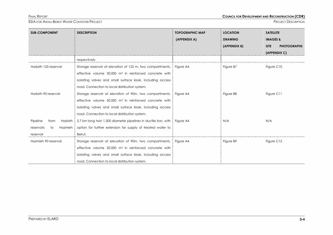
FINAL REPORT COUNCIL FOR DEVELOPMENT AND RECONSTRUCTION (CDR)
ESIA FOR AWALI-BEIRUT WATER CONVEYER PROJECT PROJECT DESCRIPTION
PREPARED BY ELARD 3-4
SUB-COMPONENT DESCRIPTION TOPOGRAPHIC MAP
(APPENDIX A)
LOCATION
DRAWING
(APPENDIX B)
SATELLITE
IMAGES &
SITE PHOTOGRAPHS
(APPENDIX C)
respectively
Hadath 125 reservoir Storage reservoir at elevation of 125 m, two compartments,
effective volume 30,000 m3 in reinforced concrete with
isolating valves and small surface kiosk, including access
road. Connection to local distribution system.
Figure A4 Figure B7 Figure C10
Hadath 90 reservoir Storage reservoir at elevation of 90m, two compartments,
effective volume 50,000 m3 in reinforced concrete with
isolating valves and small surface kiosk, including access
road. Connection to local distribution system.
Figure A4 Figure B8 Figure C11
Pipeline from Hadath
reservoirs to Hazmieh
reservoir
2.7 km long twin 1,300 diameter pipelines in ductile iron, with
option for further extension for supply of treated water to
Beirut.
Figure A4 N/A N/A
Hazmieh 90 reservoir Storage reservoir at elevation of 90m, two compartments,
effective volume 20,000 m3 in reinforced concrete with
isolating valves and small surface kiosk, including access
road. Connection to local distribution system.
Figure A4 Figure B9 Figure C12

FINAL REPORT COUNCIL FOR DEVELOPMENT AND RECONSTRUCTION (CDR)
ESIA FOR AWALI-BEIRUT WATER CONVEYER PROJECT PROJECT DESCRIPTION
PREPARED BY ELARD 3-5
Figure 3-1 Geographic location of project components

FINAL REPORT COUNCIL FOR DEVELOPMENT AND RECONSTRUCTION (CDR)
ESIA FOR AWALI-BEIRUT WATER CONVEYER PROJECT PROJECT DESCRIPTION
PREPARED BY ELARD 3-6
Component 2 will comprise the following:
The construction of 16 reservoirs (between 500 m3 and 1000 m3 storage capacity each) and
associated pumping stations distributed across the various distribution zones in the project
area;
The replacement and/or installation of approximately 187 km of distribution network across the
project area in Ein El Delbi, Southern Beirut and parts of the Metn area;
Installation of 200,000 household meters in portions of the project area to be selected by the
GBMLWWE and to operate on a volumetric tariff basis;
Installation of bulk meters at the reservoirs and distribution chambers;
Table 3-2 and Table 3-3 show characteristics of the above mentioned reservoirs and pumping
stations along with areas they serve. This information is to be confirmed in final stages of the
design of the second component.
Table 3-2. Description of Reservoirs
SERVED ZONE RESERVOIR NAME CAPACITY
(M3)
ELEVATION
(M)
Naame - Dmaour
Damour 500 125
Naame Nord Bas 500 100
Naame Nord Haut 500 200
Khalde - Aaramoun
Aaramoun Sud Bas 500 100
Aaramoun Sud Haut 500 220
Khalde Bas 500 120
Khalde Haut 500 250
Choueifet
Qobbe Bas 500 100
Qobbe Haut 500 220
Oumara 500 260
Choueifet Bas 1000 125
Kfarshima
Kfarshima Bas 1000 80
Kfarshima Haut 1000 200
Bsaba 500 340
Hadath Haut Hazmieh Hadath 2000 190
Hazmieh
Baabda Bas Baabda 2000 290
Fiyadiyeh Bas
Table 3-3. Description of Pumping Stations

FINAL REPORT COUNCIL FOR DEVELOPMENT AND RECONSTRUCTION (CDR)
ESIA FOR AWALI-BEIRUT WATER CONVEYER PROJECT PROJECT DESCRIPTION
PREPARED BY ELARD 3-7
NAME Q(M3/D) Q(M3/H) HMT(M) POWER (HP) POWER (KW)
Naame Nord Bas 1500 63 110 39 29
Aaramoun Sud Bas 1500 63 130 46 34
Khalde Bas 1500 63 140 49 37
Qobbe Bas 1500 63 140 49 37
Choueifet Bas 4000 167 160 148 111
Kfarshima Bas 4000 167 140 130 97
Kfarshima Haut 1000 42 150 35 26
Hazmieh 24000 1000 65 361 271
Hazmieh Hadath 7000 292 110 178 134
A map illustrating the various Distribution zones and Reservoir locations is attached to Appendix M.
3.2 CONSTRUCTION ASPECTS
The construction methodology is based on that of the feasibility study. Expected periods of construction
and the nature and quantities of excavated material to be produced are provided in Table 3-3 for
each sub-component. Technical precautionary measures will be taken for all structures to meet seismic
construction specifications. Construction phase is expected to be completed within three years.
3.2.1 Tunnels
The expected rock type to be encountered while drilling the tunnel is strong, permeable limestone. This
rock type should be self-supporting after the tunneling works. The groundwater table lies well below the
tunnel level and is not expected to cause any significant problem during construction. At valley
crossings, such as the Nahr Damour crossing whereby alluvial deposits will be encountered the tunnel
construction will be lined and impermeable.
The tunneling will be carried out mainly using a tunnel boring machine (TBM). New or improved access
roads will be required for the equipment to reach the tunnel portals. The TBM will be deployed at the
following sections:
- From Ourdaniye WTW to Joun regulation structure
- From Ourdaniye WTW to Nahr Damour; and
- From Khalde to Nahr Damour

FINAL REPORT COUNCIL FOR DEVELOPMENT AND RECONSTRUCTION (CDR)
ESIA FOR AWALI-BEIRUT WATER CONVEYER PROJECT PROJECT DESCRIPTION
PREPARED BY ELARD 3-8
The “cut and cover” excavation method will be used at the Nahr Damour inverted siphon rather than
the TBM. A substantial cofferdam is likely to be required to cross the river. Environmental implications of
the cofferdam will have to be examined and addressed once the final design is completed.
The vertical shaft of the inverted siphon will be formed by “raise boring”. A hole will be drilled from the
surface and raise boring machine assembled in the bottom of the low level tunnel. This will be gradually
raised to the upper level tunnel. Spoil will be discharged at a low level, i.e. at the base of Nahr Damour
Valley. The tunnels will be formed with in-situ reinforced concrete lining with an external impermeable
membrane to reduce leakage and, in some cases, the addition of a steel liner. A schematic hydraulic
profile and cross-sections along the tunnel are given in Figure 3-2, Figure 3-3 and Figure 3-4,
respectively.
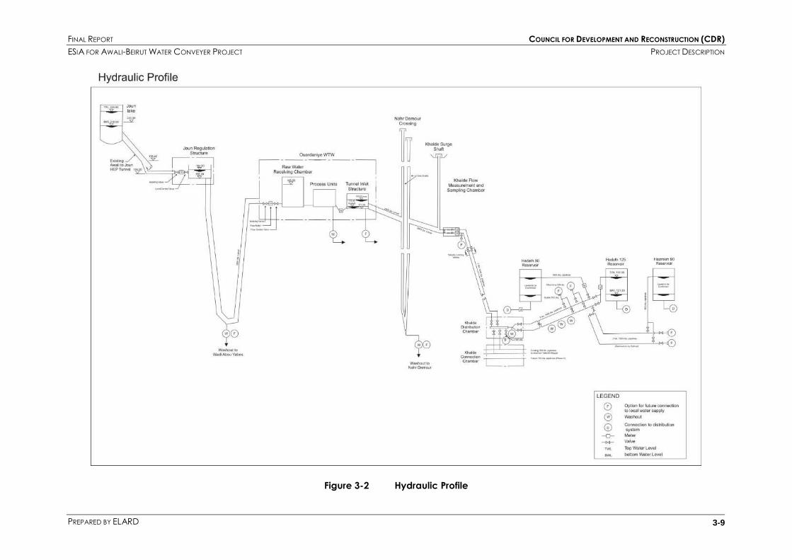
FINAL REPORT COUNCIL FOR DEVELOPMENT AND RECONSTRUCTION (CDR)
ESIA FOR AWALI-BEIRUT WATER CONVEYER PROJECT PROJECT DESCRIPTION
PREPARED BY ELARD 3-9
Figure 3-2 Hydraulic Profile

FINAL REPORT COUNCIL FOR DEVELOPMENT AND RECONSTRUCTION (CDR)
ESIA FOR AWALI-BEIRUT WATER CONVEYER PROJECT PROJECT DESCRIPTION
PREPARED BY ELARD 3-10
Table 3-4 Estimated Spoil Generation
SOURCE SPOIL MATERIAL QUANTITY PROPOSED PERIOD OF GENERATION RATE OF GENERATION
METHOD OF EXCAVATION DESCRIPTION OF SPOIL FROM
MONTH
TO
MONTH
TOTAL
MONTHS IN AVERAGE
MONTH
IN MAXIMUM
MONTH
tonnes no. no. no. t/month m3/month
Joun Regulation
Structure Drill and Blast Limestone and dolomite rock
650
1 4 4 160 -
Ouardaniye Inlet
Portal-Tunneling Tunnel Boring Machine Limestone and dolomite rock 169,000 1 17.5 17.5 9,600 **
Drill and Blast Limestone and dolomite rock 480 1 1 1 180 -
Ouardaniye WTW Open Cut Limestone and dolomite rock 557,500 1 12 12 - -
Fill Suitable tunnel spoil (326,000) 15 27 12 - -
Ouardaniye Outlet
Portal-Tunneling Tunnel Boring Machine Limestone and dolomite rock 241,500 1 25 25 9600 **
Drill and Blast Limestone and dolomite rock 480 1 1 1 180 -
Nahr Damour Excavation of River Crossing- Cut
and Cover
Alluvium 1,410 1 18 12* 120 -
Drill and Blast Alluvium and Limestone and
dolomite rock
33,500 19 41.5 22.5* 1,500 -
Khalde Outlet Portal Tunnel Boring Machine Limestone and dolomite rock 189,000 1 19 19 9,900 **
Drill and Blast Limestone and dolomite rock 480 1 1 1 180 -
Pipeline - Khalde
Outlet Portal to
hadath Reservoirs
Surface excavation, drill and
blast ***
Limestone and residual clays 325,000 to be defined - -
Hadath 90 Reservoir
Surface excavation, drill and
blast ***
Limestone and residual clays 96,000 to be defined - -
Hadath 125 Reservoir
Surface excavation, drill and
blast ***
Limestone and residual clays 124,800 to be defined - -
Pipeline - Hadath
Reservoirs to Hazmieh
90 Reservoir
Surface excavation, drill and
blast ***
Limestone and residual clays 62,000 to be defined - -
Hazmieh 90 Reservoir
Surface excavation, drill and
blast ***
Limestone and residual clays 24,000 to be defined - -
Pipeline - Khalde to
Tellet el Khayat
Reservoir
Surface excavation, drill and
blast ***
Limestone and residual clays 110,000 to be defined - -
TOTAL 1,609,800
* working only October to April ** to be identified from contractor's methodology
*** all excavated material will be removed from site due to limited working area

FINAL REPORT COUNCIL FOR DEVELOPMENT AND RECONSTRUCTION (CDR)
ESIA FOR AWALI-BEIRUT WATER CONVEYER PROJECT PROJECT DESCRIPTION
PREPARED BY ELARD 3-11
Figure 3-3 Cross-Section Joun-Ouardaniye Tunnel

FINAL REPORT COUNCIL FOR DEVELOPMENT AND RECONSTRUCTION (CDR)
ESIA FOR AWALI-BEIRUT WATER CONVEYER PROJECT PROJECT DESCRIPTION
PREPARED BY ELARD 3-12
Figure 3-4 Cross-Section Ouardaniye-Khalde Tunnel

FINAL REPORT COUNCIL FOR DEVELOPMENT AND RECONSTRUCTION (CDR)
ESIA FOR AWALI-BEIRUT WATER CONVEYER PROJECT PROJECT DESCRIPTION
PREPARED BY ELARD 3-13
3.2.2 Ouardaniye WTW
The proposed site of the Ouardaniye WTW is characterized by moderate slopes and easy access.
However, access roads will require some improvements before start of construction. The site will be
excavated up to 12m deep in rock by means of drilling and blasting. A suitable site will be required for
disposal of the excavated material from the WTW and the tunnels. Some could be crushed and used as
backfill material on site of the Ouardaniye WTW.
The buildings and structures associated with the WTW will be designed in a manner which reflects the
nature and exposure of the site and its location and takes into account local aesthetics and building
practices. Since the process structures will all be in reinforced concrete, this material will also be used
for the associated building to provide low maintenance, functional facilities.
The WTW site will be landscaped in a manner appropriate to the fairly harsh environment, with low
maintenance planting. The perimeter of the WTW will be marked with a suitable security fence, with
entry controlled at a gatehouse built into fencing. Site lighting will be provided by high pressure sodium
floodlights over process units, working areas and roads. Perimeter and security lighting will be provided
in accordance with the prevailing local practice of major WTW.
Chemical and storage fuel tanks will be bonded, and suitable precautions adopted for chemical
(especially chlorine gas) storage.
An emergency overflow (600mm diameter) will carry overflow water from the treatment units along the
upgraded access road, discharging into a local stream course below the new coastal highway, and
then ultimately into the sea or into groundwater.
Storm water from the treatment works site will discharge through a 600mm diameter pipe to the north
into Wade Baraz and likewise into the sea or into groundwater.
3.2.3 Pipelines
Excavation for the twin ductile iron pipelines from Khalde Tunnel Portal to the Khalde Flow Distribution
chamber and then on to the Hadath and Hazmieh Reservoirs will be up to 10m wide and 2.5m – 3.0m
deep. However, at road, river, and culvert crossings, deeper excavations may be required, especially
at the Ghadir River crossing. Heavy rippers and rock breakers might be used in areas with strong
limestone to reach formation level. Blasting will be required for excavation through the hill side below
the Hadath reservoir.
Excavation in alluvial and raised beach deposits should not present any significant problems but the
stability of the resulting excavation will depend on the precise groundwater level. Construction of the
twin 1400mm diameter ductile iron pipelines from Khalde to Hadath Reservoir partly along Chouwaifat
road will be through a heavily built up area with significant, but substantially unrecorded underground
services. The same applies to the twin 1300mm diameter ductile iron pipes from Hadath to Hazmieh
Reservoir.
3.2.4 Distribution Chamber and Reservoirs
The Joun Regulation Structure will be constructed in an area of strong limestone rock requiring drilling
and blasting below the layer of alluvial deposits as well as the Wadi Abou Yabes washout.

FINAL REPORT COUNCIL FOR DEVELOPMENT AND RECONSTRUCTION (CDR)
ESIA FOR AWALI-BEIRUT WATER CONVEYER PROJECT PROJECT DESCRIPTION
PREPARED BY ELARD 3-14
At the Khalde Distribution Chamber the rock is not expected to be found close to the surface and the
majority of the excavated material is likely to be sand fill with rock fragments. Some drilling and blasting
may be needed at formation level. A 450mm diameter emergency washout pipeline will discharge
from the chamber to an adjacent dry stream bed.
Blasting will be required at the sites of the proposed Hadath and Hazmieh Reservoirs.
3.2.5 Working Areas
Temporary contractors‟ working areas will be required for each of the main project components. These
will have workshops, concrete batching plants, spoil handling facilities, etc., where appropriate. These
areas are expected to be within the expropriated land for construction of the component. However,
some additional working areas may be required. The extent of these will have to be defined at a later
stage after receiving the proposal of the Contractor.
3.2.6 Access Roads
New roads are required to be constructed and some existing road to be improved to allow suitable
access for the construction traffic and in some cases operational vehicles, to a number of the project
components. Table 3-5 summarizes the required access roads.
Table 3-5 Description of New Access Roads
ACCESS ROAD STATUS LENGTH WIDTH
Joun Regulation Structure Temporary About 1.6 km 8 m
Wadi Abou Yabes Washout Permanent About 2.5 km 8 m
Ouardaniye WTW Permanent About 2 km 10 m
Nahr Damour – South tunnel adit Temporary About 3.5 km 8 m
Nahr Damour – North tunnel adit Temporary To be defined To be defined
Nahr Damour – South ventilation shaft Temporary To be defined To be defined
Nahr Damour – North ventilation shaft Temporary To be defined To be defined
Khalde Portal Temporary About 0.7 km 8 m
Hadath 125 Reservoir Permanent 0.1 km 10 m
Hadath 90 Reservoir Permanent 0.01 km 10 m
Hazmieh 90 Reservoir Permanent 0.01 km 10 m
3.3 OPERATIONAL ASPECTS
3.3.1 Sources of Water
Table 3.6 shows the sources of supply of the proposed project and indicates the range of flows coming
from each throughout the year. However, operation of this project will be greatly influenced by the
operation of the Joun Hydro Electric Power plant (HEP) system and by the season. These factors will also
affect the water quality.
Upstream Joun Lake, the Karaoun Lake collects water from the Litani River impounding a total volume
220 Mm3 of water. Priority of allocation of this water is given to irrigation and drinking purposes. 30 Mm3

FINAL REPORT COUNCIL FOR DEVELOPMENT AND RECONSTRUCTION (CDR)
ESIA FOR AWALI-BEIRUT WATER CONVEYER PROJECT PROJECT DESCRIPTION
PREPARED BY ELARD 3-15
are used for irrigation in Tyre, Saida and other southern villages whereas a volume of 40Mm3 is to be
maintained for the Lake. The remaining 150 Mm3 are used for generating hydroelectric power at the
stations shown in Table 3-6.
Table 3-6 Hydroelectric Power Plant Chracteristics
HEP ELEVATION MAXIMUM DISCHARGE INSTALLED POWER
Markaba 658 m 22 m3/s 34 Mw
Awali 228.5 m 33 m3/s 108 Mw
Joun 32 m 33 m3/s 48 Mw
In the dry season, the main source of water will be the Karaoun Lake. Water will be drawn from the
Karaoun Reservoir (capacity 220 Mm3).
In the wet season, the source may be both the Karaoun Lake and the Awali River. The Awali River is a
mountain stream on the western side of the Mount Lebanon range. Upstream of the Joun Lake and the
Awali HEP, the catchment area is about 300 Km2.
The flow of Awali is seasonal and highly variable, averaging 3.0 m3/s, but varying from 0.1 m3/s in late
summer to 30 m3/s and over during spring runoff.
Some of the flow from Litani and most of the flow from the Awali are combined in Joun Lake (also
known as the Awali compensation basin). This is located immediately downstream of the Awali HEP,
before up to 30 m3/s of flow is passed through the existing Joun tunnel to the Joun HEP. Residual flow
from the Awali River is passed along the natural river channel.

FINAL REPORT COUNCIL FOR DEVELOPMENT AND RECONSTRUCTION (CDR)
ESIA FOR AWALI-BEIRUT WATER CONVEYER PROJECT PROJECT DESCRIPTION
PREPARED BY ELARD 3-16
Figure 3-5 Schematic Drawing of Water Resources
The existing HEP system is operated as a power peaking system for approximately four hours per day.
During periods of high flow in the Awali River (December to April), the final stage of the system (Joun
HEP) may be operated 24 hours per day. Under these conditions, the maximum flow which can be
diverted to the Awali project may have to be limited to 2.5m3/s for part of the 4 hour peak period of
power generation. Table 3-7 summarizes key factors determining source of water.
Table 3-7 Key Factors Determining the Source of Water
SEASONAL CONDITION HEP OPERATIONAL
CONDITION
SOURCE DIVERSION
Awali River flow exceeds
3m3/s
Off-peak hours Awali River 3 m3/s
Wet Season Peak hours Litani River 2.5 m3/s
Dry Season (flow < 3m3/s) Litani River 3 m3/s
3.3.2 Joun Regulation Structure
The raw water flow will be self-regulated at the Joun Regulation Structure by means of a level control
valve.

FINAL REPORT COUNCIL FOR DEVELOPMENT AND RECONSTRUCTION (CDR)
ESIA FOR AWALI-BEIRUT WATER CONVEYER PROJECT PROJECT DESCRIPTION
PREPARED BY ELARD 3-17
The velocity limiting valves upstream are also designed to close in the event of failure of the level
control valve.
This structure will normally be unmanned. It will be inspected for maintenance every month.
3.3.3 Tunnel and Pipelines
There is a risk of build-up of deposits at the low points in the tunnel system in the Joun – Ouardaniye
inverted siphon and to a much lesser extent in the Nahr Damour inverted siphon. Slight opening of the
washout valves at Wadi Abou Yabes and Nahr Damour every 6 (six) months will be sufficient to scour
out any deposits.
It is recommended that the whole tunnel and pipeline system be emptied every 5 (five) years for an
overall internal inspection. It can be partially drained by allowing the water level to be lowered by
normal usage except for the Joun-Ouardaniye WTW section which would be drained from the 700mm
washout at Wadi Abou Yabes, the 900mm washout at Nahr Damour inverted siphon and a number of
washouts on the Khalde to Hadath/Hazmieh pipelines.
Air valves and 250 – 400mm diameter washouts will be provided at high and low points respectively
along the proposed pipelines from Khalde to Hadath and Hazmieh. Washouts will discharge water to
dry stream beds. Air valves will result in only occasional discharges of air which has come out of solution
or entered the pipeline during maintenance, whilst the washouts will operate only during emergency or
planned maintenance.
The tunnel system will also be inspected in the event of significant seismic activity.
3.3.4 Ouardaniye WTW
The Ouardaniye WTW will be operated by a staff of 25 to 30 persons. It will operate automatically for 16
hours per day, with a shift system of staff covering operation outside normal working hours. The overall
system control will be from a Central Control Room including monitoring and control of raw and
treated water quality. Works throughput will be set daily to satisfy anticipated demand and the water
levels in the Hadath and Hazmieh Reservoirs. In the event of the reservoirs and tunnel being full, the
rising water level at the WTW outlet will be used to control throttling of the inlet flow at Joun.
The treatment plant is designed to have the capacity of treatment of 9m3/s flow of water if additional
water resources are supplied in the future.
Table 3-8 and 3-9 summarize respectively the inputs and outputs arising during normal operation of the
works and indicate the vehicular movements required. These are subject to modifications after final
stage design.
Table 3-8 Ouardaniye WTW –Mean Operational Inputs and Vehicular Movements
OPERATIONAL INPUT MEAN INPUTS/DAY MEAN VEHICULAR MOVEMENTS
REQUIRED
Ferric Chloride (liquid) 6.6 tones 40/month
Cationic Polymer (liquid) 270 kg 2/month
Anionic Polymer (powder) 50 kg 0.5/month
Caustic Soda (liquid) 5.6 tones 35/month

FINAL REPORT COUNCIL FOR DEVELOPMENT AND RECONSTRUCTION (CDR)
ESIA FOR AWALI-BEIRUT WATER CONVEYER PROJECT PROJECT DESCRIPTION
PREPARED BY ELARD 3-18
OPERATIONAL INPUT MEAN INPUTS/DAY MEAN VEHICULAR MOVEMENTS
REQUIRED
Chlorine (gas) 1.0 tone 15/month
Ammonia (liquid) 0.4 tones 3/month
Spare Chemicals 130 kg 1/month
Fuel Oil Emergency use only Assume 1/month
WTW Staff 25-30/day 15 cars/day
Table 3-9 Ouardaniye WTW –Mean Operational Outputs and Vehicular Movements
OPERATIONAL OUTPUT RANGE OF OUTPUT VEHICULAR MOVEMENTS
REQUIRED
Sludge liquid 4,500 – 10,700 m3/d N/A
Sludge – dewatered (to 15%) to
quarry or landfill
11 – 200 tones/d 2 – 28 tankers/d
Works overflow (emergency ) to sea Up to 0.5 to 1 m3/d max for short
periods
-
Chemicals and consumables
packaging and containers and
canteen waste
Quantities to be identified Quantities to be identified
Overflows capable of discharging a fraction of the WTW‟s capacity (up to about 1000 l/s) during
operational changes will be removed by a 600mm diameter pipeline following the route of the WTW
access road and discharged to a dry stream bed and thence into the sea. Emergency drainage from
the flocculators, clarifiers, rapid gravity filters and filter wash water will follow the same route.
During commissioning of the WTW and the conveyor system, production water will be discharged
through the emergency outfall or through the washouts. Chlorinated water will be de-chlorinated prior
to discharge.
Surface water drainage from the WTW will be designed for a storm with a 1 in 20 year return period and
will be routed to Wadi Baraz to the north of the WTW site. At the lower end, the wadi will require
improvement by the construction of a concrete channel to direct flow to the culverts under the coastal
road and railway, and an outfall structure under the beach. Petrol/oil will be provided where
appropriate and drainage from the area in front of the Chemical House will be separated and routed
to a chemical drain system which serves the chemical loading and handling areas. The system will
discharge to the sludge thickening plant for disposal to landfill with the sludge.
Foul sewage from the WTW will be collected and treated in accordance with accepted local
technology. In the absence of a local sewer system, a properly designed septic tank or small treatment
works will be installed.
3.3.5 Khalde Surge Structure
The Khalde Surge Structure will be unmanned. It will be inspected for maintenance annually. Detailed
surge analysis will be used in the design process to ensure that the surge shaft structure will not overflow

FINAL REPORT COUNCIL FOR DEVELOPMENT AND RECONSTRUCTION (CDR)
ESIA FOR AWALI-BEIRUT WATER CONVEYER PROJECT PROJECT DESCRIPTION
PREPARED BY ELARD 3-19
and flood adjoining land. The shaft and its compound will be equipped with appropriate safety
measures to prevent the ingress of foreign bodies into the treated water.
3.3.6 Khalde Flow measurement and Sampling Chamber
The Khalde Measurement and Sampling Chamber will also be unmanned. However, as it is the point at
which the Contractor will be contractually required to deliver treated water, it will be visited daily for
water sampling. Upkeep and maintenance will be the responsibility of the Contractor.
Immediately downstream of this Chamber will be velocity limiting valves which will close in the event of
catastrophic failure of the downstream pipelines.
3.3.7 Khalde Distribution Chamber
The operation of the unmanned Khalde Distribution Chamber will be the responsibility of the BMLWE,
which will operate the distribution valves manually.
3.3.8 Hadath 90 and 125 and Hazmieh 90 Reservoirs
The Hadath and Hazmieh Reservoirs will be unmanned structures and also the responsibility of the
BMLWWA. Information on water level and water quality will be transmitted to the Central Control Room
at the Ouardaniye WTW. Emergency re-chlorination will be provided at the reservoirs using mobile
facilities.
3.4 WATER QUALITY AND TREATMENT PROCESS
3.4.1 Raw Water Quality
The raw water will be delivered to the plant by the use of tunnels that belong to the existing
hydroelectric system. There are two main sources of water:
3. Karaoun lake;
4. Awali River.
The quality for each source over the period of at least a full year must be analyzed in detail before
start of construction phase. For this purpose a new sampling campaign was adapted and had started
in April and is still ongoing.
The source of water supply is very important to the project as the Karaoun lake and Awali River differ
from each other in terms of water quality. According to past water quality monitoring data which
formed the basis for previous studies and designs, the Karaoun lake has a better water quality when
compared to the Awali source. This may have been affected however by reported increase in
industrial and agricultural activity in the lower Beqa‟a valley, the feeder catchment of the Litani River.
Raw water quality has been analyzed several times in the past with the first one being in 1968/1972, the
second one in August 1984 and the third one in 1994/1995. The most recent water quality analysis was
conducted in 2001. The first two can be considered outdated as it is suspected that the condition and
status of the tunnels, hydroelectric power plant and dams may have changed during the proceeding
period. The analysis conducted in 1994/1995 contained some information on the most important
parameters; however the feasibility report and the preliminary design report of Montgomery Watson did

FINAL REPORT COUNCIL FOR DEVELOPMENT AND RECONSTRUCTION (CDR)
ESIA FOR AWALI-BEIRUT WATER CONVEYER PROJECT PROJECT DESCRIPTION
PREPARED BY ELARD 3-20
not cover comprehensive water quality information on a seasonal basis for both the Karaoun and Awali
sources.
The 2001 analyses provided further and detailed information on specific chemical substances and also
herbicides/pesticides which seemed to be either below the detection limits or lower than the effluent
requirements. Specific and detailed assessment will be provided in a later stage. The results did not
indicate issues that could have had a potential impact on the treatment scheme. In fact, the water
quality did not differ much from the one given in the earlier feasibility report, however it is noteworthy
that the 2001 sampling and analyses campaign seemed to be limited in the number of samples taken
and lacking in seasonal water quality results which is the most crucial information that must be
obtained for finalizing the treatment scheme.
The 2001 analyses report contains information on separate water sources such as the Awali and Litani
Rivers, based on samples taken in winter and spring of 1994/1995. This information could not be located
in the 1994 feasibility report.
From a treatment plant design perspective, this information was found to be more valuable as it
showed how both sources deteriorated in quality in winter when it is suspected that wet weather events
might have occurred although these have not been clearly stated. It is therefore prudent to take into
consideration the results obtained from the sampling and analysis program conducted in 1994 and
1995.
The new sampling and analysis campaign to determine the current water quality of the Litani and
Awali sources must be a combination of the 1994/1995 and 2001 analyses. The combination can be
defined by the need:
I. To derive the seasonal water quality and associated changes;
II. To include all the chemical, microbiological and indicator parameters as outlined and
classified in the latest 98/83/EC drinking water directive and the Lebanese Environmental
Quality Standards & Criteria for water listed in Ministerial Decision No. 52/1, MoE.
The results of the sampling and analysis campaign are given in Appendix O.
Apart from the numerical results, both the Awali and Litani sources were characterized as being
noncorrosive, moderately hard and low in organics. It was also observed that there were no point
discharges of wastewater of either domestic or industrial type. However, due to agricultural activities,
pesticides could be a threat to the water source and testing of this regard must be made a key
consideration during the engineering design.
It is not possible to immediately verify the conclusions and assumptions which were the basis of the 1994
feasibility study or the subsequent preliminary design. This is due to lack of recent detailed water quality
monitoring data at the points of concern to this project, and the fact that new data would need to be
collected over long periods to capture seasonal variations. Accurate up-to-date analysis results will not
only help in a better and an efficient design of the potable water treatment plant but also aid in
defining the chemical dosage and consumption. It is noteworthy that the correct selection and dosing
requirement of the coagulation chemicals will have to be determined via jar tests which have not been
done up to now. The raw water quality as estimated in the 1994 feasibility report is shown in Table 3-10.,
based on the combined range of quality parameters from both the Liatni and the Awali sources

FINAL REPORT COUNCIL FOR DEVELOPMENT AND RECONSTRUCTION (CDR)
ESIA FOR AWALI-BEIRUT WATER CONVEYER PROJECT PROJECT DESCRIPTION
PREPARED BY ELARD 3-21
Table 3-10 Raw Water Quality
PARAMETER UNIT MEAN MAXIMUM MINIMUM
Temperature oC 14 18 10
PH 8 (typ) 8.4 6.9
Color PE/Co 2.0 7.5 1.0
Turbidity FTU 20 155 1
Suspended Solids mg/L 14 28 6
Conductivity µS/cm 265 409 200
TDS mg/L
(CACO3)
253 288 232
Alkalinity mg/L
(CaCO3)
158 240 140
Hardness mg/L 175 240 150
Calcium mg/L 58 80 42
Magnesium mg/L 9 12 5
Sodium mg/L 10 13 7
Ammonia mg/L 0.1 0.4 0
Nitrate mg/L 0.9 1.0 0.7
Chloride mg/L 18 25 12
Fluoride mg/L 0.12 0.15 0.07
Iron mg/L 0.16 0.33 0.1
BOD mg/L 2.6 5.5 0.9
Dissolved Oxygen mg/L 5.1 11.8 1.0
Coliforms No./100mL 115 370 5
THM Potential mg/L <34 <21
Total Organic Carbon mg/L 0.7 0.93 0.58
The influent parameters suggest that the raw water has a mild to moderate quality. However due to
variable raw water quality linked to seasonal changes especially for the Awali source; specific new
analysis should be conducted to determine the raw water quality during wet weather events. There is
no information as to when the sampling and analysis were conducted to derive the above given water
quality, and most important of all, it is not known whether the maximum values correspond to wet
weather events or they are the maximum influent parameters corresponding to the dry season.
Seasonal raw water analysis plays an important role in defining the water quality and hence the most
efficient and economical process. Furthermore, manganese concentration is missing in the estimated
raw water quality which has a prime importance in the design.
The result of raw water analysis conducted on specific sources in 1994 and 1995 are summarized in
Table 3-11. Only the parameters which have significant importance to the process have been shown. It
can be seen that influent parameters vary greatly between summer and winter months and can reach

FINAL REPORT COUNCIL FOR DEVELOPMENT AND RECONSTRUCTION (CDR)
ESIA FOR AWALI-BEIRUT WATER CONVEYER PROJECT PROJECT DESCRIPTION
PREPARED BY ELARD 3-22
to very high levels especially for suspended solids and turbidity. Again, it is clearly illustrated that the
Litani River source has a better quality than the Awali River source.
Table 3-11 Water Quality Analysis (1994 and 1995)
PARAMETER 14.02.1994 04.07.1994 13.01.1995
Awali Litani Awali Litani Awali Litani
TSS (mg/L) n/a n/a n/a n/a 22 14
Turbidity (NTU) 150 80 n/a n/a 5.5
T, Coliform (No./100mL) n/a n/a n/a n/a 67
pH 8.2 7.8 n/a n/a 7.1
PARAMETER 07.02.1995 18.03.1995 18.05.1995
TSS (mg/L) n/a n/a 110 n/a 16 14
Turbidity (NTU) 350 22 59 n/a 0.7 1.8
T, Coliform (No./100mL) n/a n/a 58 n/a 0 3
pH 8.1 7.7 7.55 n/a 7.5 7.3
It is suspected that the samples taken on 14.02.1994, 07.02.1995 and 18.03.1995 may have coincided
with wet weather events however nothing has been noted to justify this. If this is the case then it can be
concluded that Awali river water quality during wet weather events deteriorates more than the Litani
source with TSS and turbidity levels reaching up to 110 mg/L and 350 NTU respectively.. It is also
important to note that inlet pH can be below 7.
It has been nearly 16 years since the last sampling and analysis campaign was conducted and it is
imperative that up to date raw water quality must be derived to validate the latest situation of the raw
water quality to be used as the basis for design. The possibility of a lower water quality in both the Awali
and Litani sources should not be ruled out as over the years, residential and commercial developments.
Increase in agricultural activity and industrialization may have affected the water sources and to
ascertain this, a new sampling and analysis campaign was recommended by Montgomery Watson.
3.4.2 Treated Water Quality
The treated water quality given in the feasibility study needs to be updated taking into consideration
the Lebanese standards and the latest amendments in various drinking water guideline standards i.e.,
WHO and EU. The feasibility study was completed in 1994; however in 1998 the European Council issued
the new drinking water directive, 98/83/EC which provides a more detailed treated water consent
under three different categories; microbiological parameters, chemical parameters and indicator
parameters. Recently the third edition of the World Health Organization (WHO), Guidelines for Drinking
Water Quality was released in 2008.
The previously recommended treated water quality targets will have to be revisited prior the start of the
project. A combination of the national standards and that of EU and WHO standards are
recommended for the Awali treatment scheme to derive a more comprehensive water quality than
the one previously defined. Each parameter will have to be evaluated one by one on the basis of their

FINAL REPORT COUNCIL FOR DEVELOPMENT AND RECONSTRUCTION (CDR)
ESIA FOR AWALI-BEIRUT WATER CONVEYER PROJECT PROJECT DESCRIPTION
PREPARED BY ELARD 3-23
effect on public health, implication on water transmission and public acceptability. The recommended
treated water quality targets are compared to standards in Table 3-12.

FINAL REPORT COUNCIL FOR DEVELOPMENT AND RECONSTRUCTION (CDR)
ESIA FOR AWALI-BEIRUT WATER CONVEYER PROJECT PROJECT DESCRIPTION
PREPARED BY ELARD 3-24
Table 3-12 Drinking Water Standards
PARAMETER
RECOMMENDED IN
1994 FEASIBILITY STUDY
EU STANDARDS WHO STANDARDS LEBANESE NATIONAL
STANDARDS (GUIDING LIMITS)
(MOE DECISION 52/1/1996
LEBANESE NATIONAL
STANDARDS (MAX
ACCEPTABLE)
Color Pt/Co 5 max - - 1 15
Turbidity FTU 0.2 (95%)
0.5 max
- - 0.4 4
Temperature oC <25 - - 12 25
pH 8.0-8.5 - 6.5 -8.5 6.5 8.5 9
Conductivity µS/cm 500 250 250 400 mS/cm @20 degrees -
Chlorides mglL 50 250 250 25 200
Hardness Mg/L
CaCo3
300 - 150-500 - -
Dissolved Oxygen % 75 minimum - <75 <70 -
TOC mg/L 2.0 - - - -
Total Coliforms Per 100 mL 0 0 0 0 -
THMs 50 0.1 mg/L 0.1 mg/L
Chlorine mg/L 5 maximum - 5
Monochloramine 3 maximum
2.5 minimum
Pesticides Total 0.1 0.1 -
Pesticides individual 0.5 0.5 -

FINAL REPORT COUNCIL FOR DEVELOPMENT AND RECONSTRUCTION (CDR)
ESIA FOR AWALI-BEIRUT WATER CONVEYER PROJECT PROJECT DESCRIPTION
PREPARED BY ELARD 3-25
3.4.3 Water Treatment Process Scheme
The proposed treatment process has been reevaluated by Montgomery Watson as part of updating
the feasibility report. The major goal was to assess its ability for fulfilling the new drinking water guidelines
and standards issued by the European Council and also the World Health Organization (WHO). When
doing this, the variable raw water quality due to seasonal changes has also been taken into account
to provide a process scheme that will be capable of treating two different raw water characters to the
desired effluent quality. The selection of appropriate chemicals that will be easy to handle, readily
available and will have the minimum impact to the process in terms of sludge production and alkalinity
consumption were considered as the key points in selecting these chemicals.
The updated and proposed new treatment scheme will comprise the following unit operations and
processes:
- Screening;
- Cascade aeration;
- Ozonation;
- Coagulation;
- Flocculation;
- Sedimentation;
- Media filtration;
- Treated water reservoir;
- Final disinfection;
- pH adjustment;
- Ammoniation;
- Thickening and dewatering of excess sludge;
- Collection of supernatant from thickening and dewatering;
- Dirty backwash collection.
The process flow diagram of the updated proposed treatment scheme can be seen in Figure 3-6 and
Figure 3-7. Two options are presented which are related to the bypass of
coagulation/flocculation/settling phases when the raw water quality is good and will not need settling.
In this case as mentioned above direct filtration will be enough to treat the water to comply with the
treated water quality. As it can be seen from the process flow diagram for the first option, the raw
water bypasses all the coagulation/flocculation and settling tanks and flows into the filters. In this case,
an inline static mixer is provided and the coagulant, flocculant can be dosed to this section of the
plant before going to the sand filters. In this option, raw water passes through ozonation for pre-
oxidation and pre-disinfection. The static mixer will aid in coagulation and flocculation. Alternatively,
the chemicals can also be dosed to the outlet of the cascade aeration structure where the turbulence
is high.
In the second option, the raw water flows through ozonation, coagulation and flocculation but
bypasses settling and flows directly to the sand filters. In this way during direct filtration the main flash
and slow mixing units will still be used for coagulation and flocculation. Both of the above mentioned
options avoid the use of secondary (intermediate mixing) mixing facilities to be utilized only during

FINAL REPORT COUNCIL FOR DEVELOPMENT AND RECONSTRUCTION (CDR)
ESIA FOR AWALI-BEIRUT WATER CONVEYER PROJECT PROJECT DESCRIPTION
PREPARED BY ELARD 3-26
direct filtration. The arrangement to be implemented should be decided by the contractor. The Awali
treatment plant will have two parallel streams.
The unit operations and processes and the justifications for the updated process scheme are discussed
separately in this section. The tentative dimensions given in the tables are for 3.09 m3/sec net inlet flow
capacity which includes 3% water losses for backwashing. Exact amount of water losses to be taken
into account for the inlet flow should be defined by the contractor.

FINAL REPORT COUNCIL FOR DEVELOPMENT AND RECONSTRUCTION (CDR)
ESIA FOR AWALI-BEIRUT WATER CONVEYER PROJECT PROJECT DESCRIPTION
PREPARED BY ELARD 3-27
RAW WATER
Ozonation
Sludge Dewatering
Cat. PolymerSludge Thickening
and Holding
Dirty BackWash
Tank
Contact Tank
Flocculation Sedimentation
H2SO4
An. Polymer or cationic for
direct filtration
Coagulation
Media Filtration
Static
Mixer
Alum
O3
Cascade Aeration
Screening
NH4OH
NaOH
CI2
Washwater
Tank
Treated Water
Tank
TO TREATED
WATER TUNNELOption 2 – To
Wadi
Supernatant TankOption 1 – To
Plant Inlet
Dewatered Sludge
Cake
Bypass during Direct filtration
During Direct Filtration
Figure 3-6 Proposed Treatment Process (Option1)

FINAL REPORT COUNCIL FOR DEVELOPMENT AND RECONSTRUCTION (CDR)
ESIA FOR AWALI-BEIRUT WATER CONVEYER PROJECT PROJECT DESCRIPTION
PREPARED BY ELARD 3-28
RAW WATER
Ozonation
Sludge Dewatering
Cat. PolymerSludge Thickening
and Holding
Dirty BackWash
Tank
Contact Tank
Flocculation Sedimentation
H2SO4
An. Polymer or cationic for
direct filtration
Coagulation
Media Filtration
Alum
O3
Cascade Aeration
Screening
NH4OH
NaOH
CI2
Washwater
Tank
Treated Water
Tank
TO TREATED
WATER TUNNELOption 2 – To
Wadi
Supernatant TankOption 1 – To
Plant Inlet
Dewatered Sludge
Cake
Bypass during Direct filtration
During Direct Filtration
Figure 3-7 Proposed treatment Process (Option2)

FINAL REPORT COUNCIL FOR DEVELOPMENT AND RECONSTRUCTION (CDR)
ESIA FOR AWALI-BEIRUT WATER CONVEYER PROJECT PROJECT DESCRIPTION
PREPARED BY ELARD 3-29
Screening
Screening has been foreseen to avoid small/large objects such as grasses, leaves, plastic debris etc
flowing to the treatment plant which can enter the raw water source in many different ways. Absence
of screens can lead to problems. It is essential to install coarse screens to protect the downstream
processes. Therefore bar screens have been foreseen with 40-50 mm opening widths. At this stage
automatically operated screens have been foreseen, however the type and operation mode of the
screen will have to be finalized by the contractor.
Aeration
Aeration involves bringing air in contact with water to transfer volatile substances from the liquid into
the gaseous phase and to dissolve beneficial gases into the water. The purposes of aeration in water
treatment are:
to reduce the concentration of taste and odor causing substances such as H2S or
other volatile organic compounds;
Oxidation of iron and manganese;
Addition of oxygen to the raw water which can be deficient in dissolved oxygen.
The available data does not suggest the necessity of aeration at first glance, however it should be
noted that the data is very limited and does not extensively cover the seasonal changes in the raw
water quality. Cascade aeration is proposed which does not involve any mechanical parts and the
oxygen transfer is solely related to the fall of the water over a number of steps. It will be a concrete
structure having three steps and each step having a 50-cm fall (Table 3-13).
The water is supplied via long tunnels so especially during the summer times the raw water could be
deficient in oxygen which can have implications on taste and odor issues. Therefore it is sensible to
construct a cascade aeration system for the Awali process scheme. One cascade aeration system can
be constructed to serve the system requirements; this should be checked by the contractor.
Table 3-13 Proposed Specifications of Cascade Aeration System
SPECIFICATION UNIT VALUE
Number of falls No. 3
Height of fall m 0.5
Number of sides No. 4
Length on each side m 7.5
Total static fall m 1.5
Width of each step m 0.6
Pre-oxidation and disinfection using Ozone
Ozone is a powerful oxidant and has many uses in water treatment, including oxidation of organic
chemicals. Ozone can also be used as a primary disinfectant. Ozone gas (O3) is formed by passing dry
air or oxygen through a high-voltage electric field. When used for the pretreatment of raw surface
water, ozone prevents the formation of THMs and other chlorinated derivatives. Ozone is more widely
used as the pre-oxidant in water treatment systems because it has a number of benefits by improving

FINAL REPORT COUNCIL FOR DEVELOPMENT AND RECONSTRUCTION (CDR)
ESIA FOR AWALI-BEIRUT WATER CONVEYER PROJECT PROJECT DESCRIPTION
PREPARED BY ELARD 3-30
clarification effectiveness (turbidity, color, residual micro-algae, OM, THM precursors) and in most cases
by reducing the coagulant demand. In many plants it has been proven that with pre-ozonation:
Coagulation and flocculation are enhanced and performance of sedimentation and
filtration processes is improved;
Odors are not created or intensified by formation of complexes;
Chlorine demand is reduced and in turn lowers chlorine dosage and so THM formation
potential;
Complex taste, odor and color problems are effectively reduced or eliminated;
Organic impurities are rapidly oxidized;
Effective pre-disinfection is achieved over a wide range of temperature and pH;
Removal of pesticides and herbicides;
Removes iron and manganese.
Ozone is now widely used in most of the conventional potable water treatment plants and the dosage
is very small which will be in the range of 0.5 to 2 mg/L. It is suspected that the dosage will not exceed
0.7-1.0 mg/L for the Awali scheme.
Available data does not necessitate the use of a pre-oxidation step at first glance, however it is
noteworthy to mention that the current available analysis results are very limited and do not cover a
year round seasonal sampling analysis. The quality of both water sources during wet weather events is
very important to conclude on the necessity of the pre-oxidation step using ozone. Nevertheless, the
following are the specific benefits of having pre-ozonation at the Awali plant:
- Will improve the performance of coagulation and flocculation and even reduce the
coagulant demand;
- Will oxidize the organics;
- Will eliminate problems with taste, odour and color;
- Will eliminate the risk disinfection byproducts (THM and other);
- Will remove the small amount of pesticides and herbicides detected in the raw water
which have strict treated water quality targets.
Intermediate ozonation has also been foreseen in the feasibility report as a future item to aid in the
removal of pesticides, herbicides, to enhance coagulation, flocculation and reduce the disinfection by
products such as THMs and chlorinated compounds. Taste and odor issues caused by disinfectants and
DBPs are best controlled through careful operation of the disinfection process. In principle, they can be
avoided by using ozone.
By the use of the process scheme given in Figure 3-6 and Figure 3-7 the water will be pre-ozonated both
during settling and direct filtration.
Concrete covered tanks will be used to provide the required ozone contact time which will be
determined by the contractor stage.
In the absence of a detailed raw water sampling and analysis campaign, it is prudent to include the
preozonation for both oxidation and pre-disinfection purposes for the Awali treatment plant. However
the final decision will be taken once the detailed analysis results are available to ascertain the present
raw water quality. The possibility of a lower water quality both for the Awali and lake Karaoun sources
should not be ruled out as over the years, residential and commercial developments, agricultural

FINAL REPORT COUNCIL FOR DEVELOPMENT AND RECONSTRUCTION (CDR)
ESIA FOR AWALI-BEIRUT WATER CONVEYER PROJECT PROJECT DESCRIPTION
PREPARED BY ELARD 3-31
activity and industrialization may have affected the water sources and to be sure, up to date sampling
and analysis should be conducted.
Table 3-14 Proposed Specification for Pre-oxidation and Disinfection.
SPECIFICATION UNIT VALUE
Location Upstream of settling tank
Detention time min 6
Max dose mg/L 2
Generators (one standby) No. 2
Capacity of each generator Kg/h 20
Ozone contact basin No. 4
Depth m 4.25
Length m 8
Width m 8
Pre-oxidation chemical O3
Pre-disinfection chemical O3
Coagulation
Coagulation is a chemical treatment process used to destabilize colloidal particles. In this process
chemicals are added to the water that either break down the stabilizing forces, enhance the
destabilizing forces, or both. Typically aluminum and iron salts are used as coagulants i.e., aluminium
sulphate, ferric chloride, ferrous sulphate etc. As mentioned earlier, although several options have been
discussed for the main coagulant in the feasibility study, ferric chloride was chosen as the chemical to
be used for coagulation. After reevaluation of the current and best practice and considering the
advantages and disadvantages of these chemicals, anhydrous aluminum sulphate is proposed as the
main coagulant.
Although both chemicals are used in water treatment processes depending on price, availability,
handling etc, aluminum sulphate has a wider usage. There are several advantages of aluminum
sulphate compared to iron salts which can be listed as:
Availability, as anhydrous aluminum sulphate is very easy to obtain (Subject to
availability on the local market);
Price, as anhydrous aluminum sulphate is cheaper compared to especially ferric
chloride (Subject to availability on the local market);
Will consume less alkalinity of natural water compared to ferric chloride (ferric based
salts will consume 0.75-0.92 mg/L CaCO3 alkalinity per 1 mg of salt dosed; alum will
consume 0.50 mg/L CaCO3 alkalinity per 1 mg of salt dosed);
Will produce less inorganic sludge compared to ferric chloride (ferric based salts will
produce 0.54- 0.66 mg insoluble precipitate per 1 mg of salt dosed; alum will produce
0.26 mg insoluble precipitate per 1 mg of salt dosed).
Apart from its advantages, handling of aluminum sulphate is slightly more complex which requires the
use of silos and feeding screws to prepare 6%-10% w/w dosing solution in flash mixing tanks.

FINAL REPORT COUNCIL FOR DEVELOPMENT AND RECONSTRUCTION (CDR)
ESIA FOR AWALI-BEIRUT WATER CONVEYER PROJECT PROJECT DESCRIPTION
PREPARED BY ELARD 3-32
Furthermore, the optimum working pH of aluminum sulphate is 6.0-7.4 which will require the dosing of an
acid (pH adjustment chemical) to reduce the pH of the incoming raw water to the desirable range
and also meet the 0.05 mg/L Al effluent consent. Since the raw water pH is in the range of 6.9-8.0, the
amount of acid to be dosed will not be significant. On the other hand, due to the addition of certain
chemicals, the natural alkalinity of the water will be consumed and a final alkalinity buffering and pH
correction will have to be done anyway. Ferric chloride has the disadvantage and possibility of leaving
a residual red color in the treated water if the process is not well controlled. This has been experienced
in some plants. Furthermore, iron promotes the growth of iron bacteria if ferrous sulphate is used. This
may cause rust-colored deposits on the walls of tanks, pipes and channels and carry-over of deposits
into the water.
However, it is very important to once again mention that the final selection of the coagulation
chemical will be done following jar tests conducted on samples taken from both water sources also
taking into consideration the availability of the chemicals in the local Lebanese market. It is also known
from previous experience that alum is a more cost effective chemical than ferric.
Coagulation will be carried out in concrete flash mixing tanks by the use of rapid mixers to provide
thorough dispersion and mixing of the chemical. The success of this unit operation depends on this.
Mechanical in-tank coagulation is necessary especially due to low raw water temperatures. It is
proposed to use two tanks in series where the first tank will receive the pH adjustment chemical and the
coagulant.
Table 3-15 Proposed Specifications for Coagulation
SPECIFICATION UNIT VALUE
Type In tank mixing
Detention time Min 1
Number No. 4 (2 in series in each stream)
Length m 3.3
Width m 3.3
Depth m 4.25
Mixer Type Turbine flash mixer
Energy Gradient S-1 750-1000
Power kW 37
Main Coagulant Al2(So4)3
pH adjustment chemical H2SO4
Flocculation
The coagulation process chemically modifies the colloidal particles so that the stabilizing forces are
reduced. To ensure that a maximum amount of turbidity is removed, mixing conditions and energy
input must be properly provided after rapid mixing to allow aggregation of destabilized particles. The
coagulated water must be gently stirred to promote the growth of flocs which can be removed by
sedimentation or filtration. The typical floc size is in the range of 0.1-2.0 mm. Jar tests will have to be
conducted to determine the correct type of polyelectrolyte i.e. anionic, non-ionic or cationic. Mostly

FINAL REPORT COUNCIL FOR DEVELOPMENT AND RECONSTRUCTION (CDR)
ESIA FOR AWALI-BEIRUT WATER CONVEYER PROJECT PROJECT DESCRIPTION
PREPARED BY ELARD 3-33
anionic types of polymers are used depending on the nature of the colloids. Metallic oxides are
generally positively charged. However most surface waters carry negatively charged colloids which
may require the use of cationic polymer. As mentioned previously, jar tests will be conducted to
determine the type of polymer to be used during settling and direct filtration. Coagulated water and
the polymer will be mixed in concrete flocculation tanks equipped with slow paddle type stirrers. To
enhance the growth of flocs tapered velocity gradient will be applied using three tanks in series.
Table 3-16 Proposed Specifications for Flocculation
SPECIFICATION UNIT VALUE
Type In tank mixing
Detention time Min 2
Number No. 6 (3 in series in each stream)
Length m 12
Width m 12
Depth m 4.25
Mixer type Paddle type slow stirrer
Energy Gradient (first compartment) S-1 60
Energy Gradient (second compartment) S-1 30
Energy Gradient (third compartment) S-1 15
Power (first compartment) kW 7.5
Power (second compartment) kW 2.2
Power (third compartment) kW 1.1
Main flocculant Anionic Polyelectrolyte
Sedimentation
Due to land constraints, lamella type plate settlers will be used. This type of settlers consists of banks of
small plates inclined at 45o to 60o angles from horizontal. The lamella plate settlers provide enhanced
solids removal because, 1) the settling distance that a particle falls to enter the sludge zone is reduced
(thus, the surface loading rate is reduced in the basin), 2) Laminar flow is achieved through the plates
(thus nearly ideal settling conditions are encountered), 3) Density currents, temperature currents and
wave action do not hinder the sedimentation process.
The sludge will be automatically removed using motorized valves and pumps. Sludge will be pumped
to sludge thickeners. Mechanical scrapers will be used to scrape the settled sludge to the hoppers.

FINAL REPORT COUNCIL FOR DEVELOPMENT AND RECONSTRUCTION (CDR)
ESIA FOR AWALI-BEIRUT WATER CONVEYER PROJECT PROJECT DESCRIPTION
PREPARED BY ELARD 3-34
Table 3-17 Proposed Specifications for Sedimentation
SPECIFICATION UNIT VALUE
Type Lamella Plate settler
Detention time min 20
Number No. 2 (one in each stream)
Specific loading rate m3/m2-h 1.0
Footprint loading rate m3/m2-h 17.9
Lamella size m 3.26 x 1.25
Lamella inclination Degree 55
Horizontal spacing mm 80
Number of lamella per unit No. 2036
Number of rows per unit No. 10
Length m 12
Width m 13
Depth m 5 – 5.5
Launder channel On top of lamella stacks
De-sludging Automatic via pumps and
motorized valves
Filtration
Further removal of colloidal particles is required to meet stringent public health standards. The filtration
process used in water treatment involves passing of the flow through a bed of granular media such as
sand, anthracite or activated carbon. As the water passes through the media, the suspended particles
are entrapped in the pore spaces of the media and thus removed from the liquid stream.
Rapid sand filters have also been foreseen in the updated process scheme as done in the feasibility
study.
Dual media sand filters are recommended with sand and anthracite which will facilitate further removal
of organics and also eliminate taste and odour problems. The filter media can also be replaced with
granular activated carbon if the necessity arises. Filters will have a combined air and water backwash
(CAW) sequence to provide the most efficient way of removing entrapped solids and this will be fully
automatic.

FINAL REPORT COUNCIL FOR DEVELOPMENT AND RECONSTRUCTION (CDR)
ESIA FOR AWALI-BEIRUT WATER CONVEYER PROJECT PROJECT DESCRIPTION
PREPARED BY ELARD 3-35
Table 3-18 Proposed Specifications for Filtration
SPECIFICATION UNIT VALUE
Type Rapid, Dual Media
Media Sand + anthracite
Number of filters No. 10
Filtration rate (1 filter offline) m3/m2-h 10.1
Required total area m2 1236
Area of each filter m2 124
Filter bed arrangement Twin bed
Length of each twin bed filter m 13.5
Width of each twin bed filter m 4.5
Media depth m 1.2m (sand) + 0.4m (anthracite)
Media effective size Mm 1.0
Number of filters backwashed No. 1
Water backwash rate (low) m3/m2-h 40
Water backwash rate (rinse) m3/m2-h 40
Air backwash Nm3/m2-h 60
Required low backwash flow rate m3/h 3645
Required rinse backwash flow rate m3/h 4860
Required air backwash flow rate Nm3/h 7290
Total washwater requirement during one
backwash
m3 510
Clean backwash tank volume m3 730
Dirty backwash volume m3 730
Design backwash duration min 17
There are two options for the dirty backwash water disposal and handling as proposed by the designer:
1) it can be discharged to the thickeners or 2) it can be directly sent to the wadi. The latter must be
further investigated and confirmed with the local regulatory authorities. The dirty backwash water tank
will be equipped with a submersible mixer to keep its content in suspension.
Post Chlorination
Post chlorination will be carried out using gas chlorine. The contact tank will have a detention time of
30 minutes and will be baffled to provide plug flow conditions. Two tanks have been foreseen for ease
of operation and maintenance. Average chlorine dose of 3.5 mg/L and a maximum dose of 5 mg/L is
expected and the capacity of the gas chlorination system has been based on this dosage.
The preliminary dimensions of each chlorine contact tank will be as follows; length=25m, width =12.5m
and the water depth will be 4.25m.

FINAL REPORT COUNCIL FOR DEVELOPMENT AND RECONSTRUCTION (CDR)
ESIA FOR AWALI-BEIRUT WATER CONVEYER PROJECT PROJECT DESCRIPTION
PREPARED BY ELARD 3-36
Treated Water Reservoir
A treated water reservoir has been foreseen to store the treated water up to a maximum of 1 hour. The
same criteria have been taken into account in the feasibility study. Two tanks each having a capacity
of 5750 m3 will be sufficient to satisfy this requirement. The tanks can be isolated with penstocks. The
preliminary dimensions of each reservoir will be as follows: length=33m, width=33m and the water depth
will be 5m. The necessity and capacity of the treated water reservoir will be reevaluated by the
contractor.
Post pH Adjustment
Chemical dosing will consume the natural alkalinity of the raw water and hence decrease the pH as
the water passes through the treatment steps. In the updated process, due to the recommendation of
alum, acid will be dosed to decrease the pH of the raw water to the desired level for optimum
coagulation. This will further reduce the buffer capacity of the water and decrease the pH. Therefore
the final treated effluent has to have the necessary alkalinity buffer and also has to be in the pH range
as given in the treated water quality.
Certain chemicals can be used for this purpose such as hydrated lime, quick lime or caustic soda. In
the feasibility study lime has been chosen because of its price. Nothing has been mentioned about lime
being more readily available than caustic. However as outlined in the same report there are a lot of
implications associated with using lime and many plants in the world have considered caustic for pH
adjustment. Below are some of the negative aspects of using lime in water treatment plants:
It is very difficult to handle. In large treatment plants it can only be stored in silos which
result in arching. It is also very dusty;
There are many impurities;
It may further increase the turbidity of the water due to these impurities. (this is
especially crucial if dosed into treated water);
Impurities from lime can settle out in pipelines and in reservoirs;
They require sophisticated storage and handling equipments;
Capital cost of lime storage and dosing facilities is high and so are the maintenance
costs.
Furthermore when dissolved in water, Ca2+ contained in lime may form CaCO3 and CaSO4
precipitates which can settle in pipes, reservoirs and cause scaling. Therefore due to the reasons stated
above, it can be concluded that technically, caustic soda is a preferred chemical to be used for post
pH adjustment. However, the final selection of the post pH adjustment chemical will be left to the final
design stage as there have been some reports that caustic is not available in the local market but can
be imported. This needs to be further investigated.
Ammoniation
Ammoniation is the process where monochloramines are formed by the addition of ammonium into the
treated water. Ammonia converts free chlorine residual to chloramines. In this form, chlorine is less
reactive, lasts longer and has fewer tendencies to combine with organic compounds thus reducing
taste and odor and THM formation. However dosage of liquid ammonia has to be carefully adjusted as
excessive amounts can lead to the formation of disinfection by products. Ammoniation process was
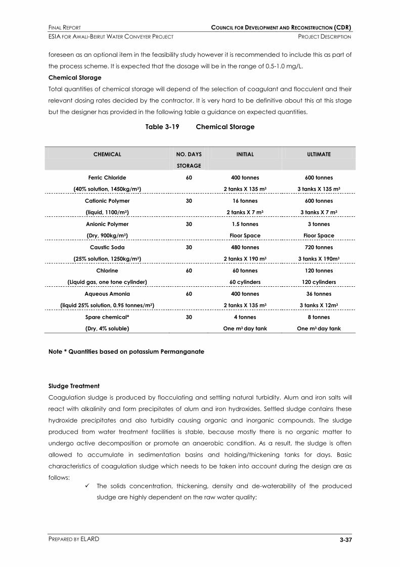
FINAL REPORT COUNCIL FOR DEVELOPMENT AND RECONSTRUCTION (CDR)
ESIA FOR AWALI-BEIRUT WATER CONVEYER PROJECT PROJECT DESCRIPTION
PREPARED BY ELARD 3-37
foreseen as an optional item in the feasibility study however it is recommended to include this as part of
the process scheme. It is expected that the dosage will be in the range of 0.5-1.0 mg/L.
Chemical Storage
Total quantities of chemical storage will depend of the selection of coagulant and flocculent and their
relevant dosing rates decided by the contractor. It is very hard to be definitive about this at this stage
but the designer has provided in the following table a guidance on expected quantities.
Table 3-19 Chemical Storage
CHEMICAL NO. DAYS
STORAGE
INITIAL ULTIMATE
Ferric Chloride
(40% solution, 1450kg/m3)
60 400 tonnes
2 tanks X 135 m3
600 tonnes
3 tanks X 135 m3
Cationic Polymer
(liquid, 1100/m3)
30 16 tonnes
2 tanks X 7 m3
600 tonnes
3 tanks X 7 m3
Anionic Polymer
(Dry, 900kg/m3)
30 1.5 tonnes
Floor Space
3 tonnes
Floor Space
Caustic Soda
(25% solution, 1250kg/m3)
30 480 tonnes
2 tanks X 190 m3
720 tonnes
3 tanks X 190m3
Chlorine
(Liquid gas, one tone cylinder)
60 60 tonnes
60 cylinders
120 tonnes
120 cylinders
Aqueous Amonia
(liquid 25% solution, 0.95 tonnes/m3)
60 400 tonnes
2 tanks X 135 m3
36 tonnes
3 tanks X 12m3
Spare chemical*
(Dry, 4% soluble)
30 4 tonnes
One m3 day tank
8 tonnes
One m3 day tank
Note * Quantities based on potassium Permanganate
Sludge Treatment
Coagulation sludge is produced by flocculating and settling natural turbidity. Alum and iron salts will
react with alkalinity and form precipitates of alum and iron hydroxides. Settled sludge contains these
hydroxide precipitates and also turbidity causing organic and inorganic compounds. The sludge
produced from water treatment facilities is stable, because mostly there is no organic matter to
undergo active decomposition or promote an anaerobic condition. As a result, the sludge is often
allowed to accumulate in sedimentation basins and holding/thickening tanks for days. Basic
characteristics of coagulation sludge which needs to be taken into account during the design are as
follows:
The solids concentration, thickening, density and de-waterability of the produced
sludge are highly dependent on the raw water quality;

FINAL REPORT COUNCIL FOR DEVELOPMENT AND RECONSTRUCTION (CDR)
ESIA FOR AWALI-BEIRUT WATER CONVEYER PROJECT PROJECT DESCRIPTION
PREPARED BY ELARD 3-38
Treatment of high turbidity surface water will result in sludge that is more concentrated
and less difficult to dewater, sludge produced from the treatment of low turbidity
surface water will be difficult to process;
Coagulation sludge from water containing high algae, will result in light and low solids
concentration;
Sludge that have a high proportion of metal hydroxides are easily dewatered because
metal hydroxides have water molecules in their structure that can separate the floc
and other particles;
Addition of polymer, lime will increase the solids concentration;
Alum sludge is a voluminous gelatinous sludge with poor compressibility. It will generally
concentrate to 0.5-3% solids in the sedimentation basin;
Sludge concentration in the settling tanks depends on how they are operated. Typical
concentration varies between 0.5-3% however this will increase if the sludge is allowed
to accumulate for some time;
Density of sludge depends on the moisture content. Normally for surface water sludge,
the density of dry sludge is in the range of 1200-1520 kg/m3.
In the 1994 feasibility study, several options have been proposed for the management of solids which
can be listed as:
Option A - Marine disposal;
Option B - Disposal at the Ras Damour Power Station;
Option C - Disposal at a nearby cement plant;
Option D - Disposal to restore local quarries;
Option E - Disposal to landfill;
Option F - Disposal to agricultural land; and
Option G - Return of raw sludge to Joun.
It was concluded in the 1998 EIA report that disposal of sludge to the marine environment (Option A)
would be an unacceptable long-term proposal, would give rise to low levels of water treatment
chemicals being present in the marine environment and would have a high capital cost. Amongst all
the alternatives given above, Option D was selected as the most viable option which is the disposal of
sludge to restore local quarries (e .g. the small quarry west of the Ouardaniye WTW) with possible future
use of the sludge as a construction material represented the best option for sludge disposal, provided
that care will be taken to avoid groundwater contamination. In the longer term, it is also stated that the
sludge may be disposed of to an engineered landfill or a wastewater treatment plant, once these are
constructed. The selected option therefore represents a flexible approach to sludge disposal.
In light of the proposed sludge management strategies given in the previous EIA study (for the short and
long term) the onsite sludge treatment has to be provided. The following steps are recommended for
the treatment of sludge:
• Sludge holding /thickening;
• Sludge dewatering (with polymer aid);
• Sludge liquor collection (supernatant tank).
As discussed earlier, alum sludge has a slimy, voluminous character which makes it difficult to process.

FINAL REPORT COUNCIL FOR DEVELOPMENT AND RECONSTRUCTION (CDR)
ESIA FOR AWALI-BEIRUT WATER CONVEYER PROJECT PROJECT DESCRIPTION
PREPARED BY ELARD 3-39
Therefore the sizing of the units and design criteria must be carefully selected.
Sludge thickening can be carried out in circular gravity thickeners which will also serve the purpose of
sludge holding and storage. Thickened sludge can then be dewatered using belt press or centrifuges.
Centrifuges have been preliminarily proposed during the feasibility study however they are costly and
energy intensive. Alternatively, belt presses are proposed at this stage as they are very low in energy
consumption and the sludge to be processed is fairly stable and will not potentially emit any malodors.
In any case belt presses can be completely covered. Cationic polymer is recommended to aid in
increasing the solids concentration and dewater ability however the selection of the type of polymer
will be done at time of construction by the contractor. A supernatant tank has been foreseen with a
reasonable detention time to collect sludge liquors resulting from thickening and dewatering processes.
Sludge yield figures for treating 250,000 m3/s and 500,000 m3/s (twice the expected capacity under the
current project) are given in Table 3-20. It depends on chemical type and dosage and whether direct
filtration or coagulation/flocculation and settling are done.
Table 3-20 Sludge Yield
ANNUAL AVERAGE MAXIMUM 72 HOURS PEAK DAY
Tonnes/day m3/d Tonnes/day m3/d Tonnes/day m3/d
For treating
250,000 m3/s
7.8 2600 31 10300 75 25000
For treating
500,000 m3/s
15.5 5200 62 20600 150 50000
The yield assumes ferric sulphate is dosed as the principal coagulant and that the clarification
produces a 0.3% so0lids sludge.
Dry solids in the sludge cake will be 230*4*12*0.97= 10,708 kg/d (10.8 tons/d). Dry solids will not change
unless the solids capture of the machine changes or more solids are produced from the liquid process
due to higher turbidity, higher chemical dosage…etc. It is the wet sludge amount that will change with
respect to dewatered sludge concentration and cake density. So for average conditions, the dry solids
in the sludge cake will be approximately 11 tons/d and the wet sludge will be in the range of 58 m3/d
to 73 m3/d dependant on the cake concentration (12-18%) for a density of 1200 kg/m3.
The conceptual sizes of the sludge treatment units are shown in Table 3-21

FINAL REPORT COUNCIL FOR DEVELOPMENT AND RECONSTRUCTION (CDR)
ESIA FOR AWALI-BEIRUT WATER CONVEYER PROJECT PROJECT DESCRIPTION
PREPARED BY ELARD 3-40
Table 3-21 Conceptual Design Parameters of Sludge Treatment Units
SPECIFICATION UNIT VALUE
THICKENING
Type Gravity
Number No. 3
Diameter M 20
Sidewater depth M 33.5
Solids loading Kg/m2-d 40
Hydraulic overflow loading Kg/m2-d 6
Scraper Picket fence type
Solids capture rate % 93-95
Thickened sludge concentration % 2-6
Thickened sludge flow m3/d 350
DEWATERING
Type Belt Press
Number No. 4
Belt width m 3
Solids throughout capacity of press Kg/h 230
Hydraulic throughout capacity of each press m3/h 7.5
Polyelectrolyte dosage Kg/ton DS 5-10
Solids capture rate % 97
Dewatered sludge cake flow m3/d 58
Dewatered sludge cake % 12-18

FINAL REPORT COUNCIL FOR DEVELOPMENT AND RECONSTRUCTION (CDR)
ESIA FOR AWALI-BEIRUT WATER CONVEYER PROJECT ANALYSIS OF ALTERNATIVES
PREPARED BY ELARD 4-1
4. ANALYSIS OF ALTERNATIVES
4.1 INTRODUCTION
This section is based on the alternative schemes presented in the initial EIA report date April 1998 and
the updated feasibility study submitted by Montgomery Watson April 2010.
An evaluation of alternative schemes to the provision of a major new water supply source for the
Greater Beirut from the Karaoun Lake and Awali Rivers is given hereunder.
4.2 NO PROJECT OPTION
Greater Beirut is likely to face serious water shortage in the near future as demand surpasses supply.
Climate change may even further exacerbate this problem. If additional sources of water supply are
not identified and provided in the near future, the following environmental and socio-economic
impacts are expected to arise:
Increase pressure on groundwater wells leading to increased salt water intrusion in the
coastal aquifers
Increased shortage periods of water in Beirut, particularly in the summer period,
possibly leading to more conflicts among water users in Greater Beirut
Not meeting Millennium Development Goals of access to water
Accordingly, the No Project alternative is considered to be not viable, as it would have severe
environmental and socio-economic impacts in Beirut.
4.3 FORMULATION OF OPTIONS
4.3.1 Constraints
Earlier Feasibility studies of 1972 and 1984 determined that the abstraction and delivery points of the
project should be:
- Abstraction at the construction adit of the Joun HEP plant tunnel prior to the HEP; and
- Delivery to the southern end of the twin 700mm diameter transmission mains at Khalde
(25km to the north) to supply reservoirs in west Beirut.
In addition the feasibility study of 1994 identified a suitable location at Hadath for a new storage
reservoir to serve East Beirut and the Southern Suburbs. The location and elevation had to achieve the
following requirements:
- Gravity Feed from Awali to Hadath;
- Equalizing supply and demand over a period of high consumption;
- Furnishing water for such emergencies as accidental breakdowns;
- Supplying water to the northern and southern suburbs, and the Achrafieh reservoirs;
- Supplying the reservoirs at Tallet El Khayat by a connection to the existing 700mm
diameter pipe at Galerie Semaan (in the event of supply shortage) to the existing twin
700mm diameter pipes (one of which is conveying water from the Damour wells); and
- Providing to regions currently supplied from other sources in case of failure of shutdown
of these sources.

FINAL REPORT COUNCIL FOR DEVELOPMENT AND RECONSTRUCTION (CDR)
ESIA FOR AWALI-BEIRUT WATER CONVEYER PROJECT ANALYSIS OF ALTERNATIVES
PREPARED BY ELARD 4-2
The development of the proposed project has been based on these requirements.
4.3.2 Water Transmission Options
Three conceptual options were identified during the various past studies to convey from Joun to Khalde
without undue head loss. These are:
- A pipeline following the hydraulic gradient around the hillsides –knows as the “hillside
Route”;
- A tunnel through the hills following the hydraulic gradient with inverted siphons or pipe
bridges to cross valleys as necessary; and
- A low elevation, high pressure pipeline following the coastal highway (which had
already been partially completed as far as Damour and was due to be extended
southwards).
The first option was ruled out immediately as being prohibitively expensive. The other two options were
carried forward to more detailed considerations in the 1994 feasibility study. The analysis was based on
two different routes and the coastal pipeline with three alternative pipeline materials. These are
discussed in sections 4.4.2.1 and 4.4.2.2
4.3.3 Water Treatment Options
It was proposed in the 1994 feasibility study that the water treatment should be designed to meet
European Union standards as minimum at that date. The new feasibility study (MWH, 2010) revises the
treatment process so that the new water guidelines and standards issued by the European Council and
also the World Health Organization (WHO) are fulfilled.
The hydraulic head limitations of the project assisted in determining the location and elevation of the
WTW.
In the 1994 feasibility study, 4 (four) locations for the WTW were considered, these are – Joun Adit, Jebel
es Sarris, Khalde and Ouardaniye.
The fourth site was selected mainly to allow gravity flow through and onwards from the WTW.
The detailed analysis of water treatment locations and treatment options are set out in section 4.4.3.

FINAL REPORT COUNCIL FOR DEVELOPMENT AND RECONSTRUCTION (CDR)
ESIA FOR AWALI-BEIRUT WATER CONVEYER PROJECT ANALYSIS OF ALTERNATIVES
PREPARED BY ELARD 4-3
4.4 DETAILED EVALUATION
4.4.1 Location of Treatment Plant
Four sites were considered in the 1994 Feasibility Study. Their characteristics are summarized in Table 4-1.
Table 4-1 Characteristics of the four proposed WTW sites
NAME LOCATION SITE DESCRIPTION LAND
AREA
(HA)
EXCAVATION
COST ($M) IN
1998
LAND
ACQUISITION
COST (1998)
LAND
ACQUISITION
COST (2010)
Joun Adit 200m West of
Joun tunnel
Adit
In a valley with
steep slopes and
poor access
6.4 – 8.5 25.9 – 35.7
3$/m2 75$/m2
Jebel
es Sarris
1.5km NW of
Joun tunnel
Adit
Moderate cross
slopes with good
access but requiring
road relocation
4.8 – 6.4 8.3 – 11.4 25$/m2 100$/m2
Ouardaniye 5km NW of
Joun tunnel
Adit
Moderate cross
slopes and good
access
4.8 – 6.2 2.3 – 9.4 25$/m2 100$/m2
Khalde 25km north of
Joun tunnel
Moderate cross
slopes and good
access
4.8 -6.3 7.0 – 9.4 110$/m2 500$/m2
All four sites had similar foundation and geological conditions, and would require extensive rock
excavation. Approximate excavation costs were estimated in the 1998 EIA report based on required
volume and depth of excavation Cost of excavation at Joun and Jebel es Sarris turned be more
expensive than that at Ouardaniye and Khalde and thus effectively ruled them out.
Both Ouardaniye and Khalde sites were considered ideally suited for the construction of the WTW.
The Khalde site is ideal in terms of elevation (to suit an entirely gravity project), space, and topography
(a reasonably gently sloping site). However, expansion of the city over years has made it relatively
expensive in terms of land purchase cost, and plots in Khalde area are being sold for private housing
development. The prime benefits of this site are:
- The close proximity to Beirut where the water is needed; and
- The reduced risk of pollution of treated water en route from Joun by sitting the plant as
close as possible to Beirut.
The Ouardaniye site offers the same essential requirements of appropriate elevation, sufficient area
and suitable topography. The prime benefits of this site are that it is:
- Considerably cheaper than Khalde in terms of current land values (US$100/m2 against
US$500/m2);
- As easily accessible as the Khalde site on completion of the coastal highway; and

FINAL REPORT COUNCIL FOR DEVELOPMENT AND RECONSTRUCTION (CDR)
ESIA FOR AWALI-BEIRUT WATER CONVEYER PROJECT ANALYSIS OF ALTERNATIVES
PREPARED BY ELARD 4-4
- Able to serve the coastal communities between Ouardaniye and Beirut from the main
transmission line between the two. This would be particularly simple in the case of the
Pipeline Option and achievable in the case of Tunnel Option 2 (see below) through
connection at the Damour Valley and other valley crossings.
4.4.2 Means of Transmission
Tunnel options (see Figure 4-1) were developed and evaluated to suit potential WTW sites:
- Tunnel Option 1: Tunnel form Joun to possible Khalde WTW; and
- Tunnel Option 2: Tunnel from Joun to possible Ouardaniye WTW plus tunnel from
Ouardaniye WTW to Khalde
A potential benefit of the pipeline option was that, provided that the water in the pipeline had been
treated, it would be comparatively simpler to connect to it for supplies to coastal communities en route
to Khalde for treatment, a more expensive site for the works. For topographical reasons a pipeline from
Joun to Ouardaniye was impractical; this section must be tunneled. Only one pipeline option was
therefore investigated:
- Pipeline Option: Tunnel from Joun to Ouardaniye WTW plus coastal pipeline from
Ouardaniye WTW to Khalde.
4.4.2.1 Considerations for Tunnel Alignment and Construction
The tunneled options have additional advantages. Tunneling through the hills permits the shortest route
towards the end point of the project. The tunnel is also able to follow the hydraulic gradient line with
less design constraints, with the exception of deep valley crossings. Due also to the minimum
economical size of a tunnel (determined as 2.8m internal diameter in the 1994 feasibility study), the
tunneled options also provide additional capacity for any future expansion, and some degree of
storage within the tunnel space itself. Most importantly, the tunneled solutions have a significantly
smaller surface disruption footprint.
In both tunnel options mentioned above, the alignments were selected to assure, as much as possible,
a straight drive on a uniform free-draining gradient in the direction of flow. Both routes deviate
eastward from the most direct alignment in order to pass under the many deep valleys, while
maintaining a minimum cover of 10m to allow for superficial deposits in the valley bottoms. This also
allowed for an adequate safety margin, assuming that a larger tunnel be adopted because of the
specific viability of a larger tunnel boring machine (TBM).
Consideration of the construction methods of the tunnels reviewed the options of drill and blast against
TBMs. The latter were considered more viable because of the lengths of the drives, because they would
give rise to smaller quantities of excavation, and since they would require the use of less concrete for
lining. TBM would also enable much more rapid progress to be made, with a consequent overall
reduction in the construction time. Drill and blast would only be used in establishing the TBMs in the first
100m of each drive.
Option 1 would give rise to significant quantities of soil at the start of the tunnel drives at the Joun and
Khalde with a smaller amount at Damour, whereas Option 2 would result in most spoil at Ouardaniye
and Khalde and a lesser amount at Joun and Damour.

FINAL REPORT COUNCIL FOR DEVELOPMENT AND RECONSTRUCTION (CDR)
ESIA FOR AWALI-BEIRUT WATER CONVEYER PROJECT ANALYSIS OF ALTERNATIVES
PREPARED BY ELARD 4-5
The tunnels would be lined with concrete and an impervious membrane to prevent leakage in either
direction. The tunnels will be drilled entirely through limestone, some of which is karstic. However, all
proposed tunnel sections are above water table and hence groundwater is not expected to cause
any problem while drilling. A steel liner with mortar lining was proposed in the shafts and bottom section
of the Damour crossing, as well as sections with minimal ground cover (such as the valley crossings and
the first and last 100m of horizontal drive from the natural ground surface).
Consideration was given to the need to provide a separate 25mm thick internal lining to the tunnel
from Ouardaniye WTW to Khalde in Option2 as it would be conveying treated water. However, the
external impermeable membrane already proposed as part of the tunnel structure was considered
adequate to prevent infiltration of contaminated water. After initial wetting, any contamination from
the concrete itself was considered not to be significant and therefore need for special protection was
deemed unnecessary.
Several factors had to be taken into consideration in the tunneled concept, such as the method for
crossing deep valleys (pipe bridges, inverted siphons, etc). It was determined during the options
development that a tunneled inverted siphon would be best, in order to maintain the integrity of the
tunneled solution. The tunnel alignment was adjusted in designs developed in 2001 to minimize the
inverted siphon drops.
The alternatives of constructing this crossing using deep trench excavation (involving a river diversion)
or tunneling were evaluated. IT was considered unlikely to be viable to set up TBMs for the two short
lengths of low level tunnel linking the vertical legs of the siphon to the crossing (only 900m and 400m
respectively on north and south sides). Drill and blast were therefore envisaged to be used at this
location.
4.4.2.2 Considerations to Pipeline
The use of the coastal highway as a route for the pipeline from Ouardaniye to Khalde is based on
planned provision of service roads on either sides of the main carriageway. Land has already been
acquired for these and the pipeline could be located under them without the need for additional land
purchase, and without the severe disruption of traffic which construction in the existing carriageway
would bring.
The pipeline option has some critical technical disadvantages. These are listed below:
- Security concerns given that an exposed rural pipeline would be very obviously
vulnerable to tampering and intentional acts of damage or foreign aggression;
- Exposure to damage from Seismic activity given that the pipe route is through
seismically active zone;
- High pressure of the pipelines (+25 bar rating requirement) due to elevation differences
could result in very severe consequences in the event of a pipe burst. Any failure in
one pipe could damage the adjacent pipe (of the twin pipes), causing complete
cessation of service. Pipe failure would also threaten local infrastructure including the
coastal freeway and adjacent properties and endanger residents;
- Extensive expropriations and service corridor requirements particularly given strong
urban development especially towards the end of the pipe route; and

FINAL REPORT COUNCIL FOR DEVELOPMENT AND RECONSTRUCTION (CDR)
ESIA FOR AWALI-BEIRUT WATER CONVEYER PROJECT ANALYSIS OF ALTERNATIVES
PREPARED BY ELARD 4-6
- Aesthetic and Environmental implications due to the extensive construction through
rural and natural areas.
Three materials (steel, ductile iron and pre-stressed concrete) were identified as feasible for the use of
the pipeline option and were therefore further evaluated by addressing issues such as flow regulation,
surge control, leakage control, corrosion and durability, and the different construction methods and
operational problems which could result.
Concrete pipes were the cheapest option as they were evaluated taking into consideration the
potential for local production. However their bursting failure mechanism (sudden brittle failure) deemed
them undesirable for the proposed application. The non-brittle Steel and Ductile Iron pipes proved
technically more appropriate given that they would exhibit puncture and leakage type failure
mechanisms which could be controlled and would not cause catastrophic failure. Steel & iron pipes
therefore adequately address the third point of the disadvantages of pipelines as listed above. They
are however, more costly even without considering the cost of extensive expropriations and land
acquisition. They also remain vulnerable to the remaining concerns regarding pipeline options.
4.4.2.3 Access Roads
Based on the proposed use of the TBMs for the main tunnel drives, Option 1 would require the
construction of temporary access roads to the working areas at El Labbiye on the southern side of the
Damour Valley and to Joun. Access to the Khalde WTW and to the tunnel working site would be via
existing roads.
In addition to the upgraded permanent access road to the proposed site of the Ouardaniye WTW,
Option 2 would require the construction of access roads to the adit at the low point of the siphon in
Wadi Abou Yabes between Joun and Ouardaniye, and to EL Labbiye on the southern side of the
Damour Valley. Upgraded existing roads would be used for access to the working sites at the other
locations.
The Pipeline Option also required a temporary access road to the adit at the low point of the siphon in
Wadi Abou Yabes between Joun and Ouardaniye and an upgraded permanent access road to the
proposed site of the Ouardaniye WTW.

FINAL REPORT COUNCIL FOR DEVELOPMENT AND RECONSTRUCTION (CDR)
ESIA FOR AWALI-BEIRUT WATER CONVEYER PROJECT ANALYSIS OF ALTERNATIVES
PREPARED BY ELARD 4-7
Figure 4-1 Altenartive Scheme Options

FINAL REPORT COUNCIL FOR DEVELOPMENT AND RECONSTRUCTION (CDR)
ESIA FOR AWALI-BEIRUT WATER CONVEYER PROJECT ANALYSIS OF ALTERNATIVES
PREPARED BY ELARD 4-8
4.4.3 Water Treatment Process
The ability to achieve a guideline value within a drinking-water supply depends on a number of factors,
including:
The concentration of the chemical in the raw water;
Control measures employed throughout the drinking-water system;
Nature of the raw water (groundwater or surface water, presence of natural background and
other components); and
Treatment processes already installed (if any).
A qualitative ranking of treatment processes based on their degree of technical complexity is given in
Table 4-2 below. The higher the ranking, the more complex the process is in terms of plant and/or
operation. In general, higher rankings are also associated with higher costs.
Table 4-2 Ranking of Treatment Processes
RANKING TREATMENT PROCESSES
1 Simple Chlorination
Plain filtration (rapid sand, slow sand)
2 Pre-Chlorination plus filtration
Aeration
3 Chemical Coalgulation
Process optimization for control of disinfection by-products
4 Granular activated carbon (GAC)
Treatment ion exchange
5 Ozonation
6 Advanced Oxidation Processes
Membrane treatment
The approach taken in defining the required treatment process was oriented towards the necessity of
treating variable raw water quality due to seasonal changes. During the summer months of dry season
the raw water is suitable for direct filtration whereas during the winter months, coagulation, flocculation
and sedimentation will be required. For this purpose, the previously proposed design allows this unit to
be bypassed and to be fed directly to filtration. Micro-coagulation and flocculation have also been
foreseen during direct filtration. The preliminary design report defines the treatment scheme as:
- Coagulation;
- Flocculation;
- Sedimentation;
- Ozone oxidation (defined to be implemented in the future);
- 2nd stage coagulation/flocculation;
- Rapid sand filtration;
- Final disinfection;

FINAL REPORT COUNCIL FOR DEVELOPMENT AND RECONSTRUCTION (CDR)
ESIA FOR AWALI-BEIRUT WATER CONVEYER PROJECT ANALYSIS OF ALTERNATIVES
PREPARED BY ELARD 4-9
- pH adjustment;
- Ammoniation;
- Sludge to be disposed to the wadi or to the sea;
- Dirty backwash collection.
The above scheme was revised in the new feasibility study mainly to fulfill the Lebanese standards of
drinking water and those of the European Union and the World Health Organization. This is addressed in
details in section 3.4.3of the Project Description
4.4.3.1 Sludge Disposal
An assessment of a wide range of sludge disposal options was made. These are summarized in the
following table:
Table 4-3 Sludge Disposal Alternatives
OPTION SUB-OPTION
A. Marine Disposal
1. Transport of raw sludge by terrestrial pipeline
westwards to the mid-point of Ouardaniye Bay, plus
about 2.4 km submarine pipeline to 30m water
depth.
2. Transport of raw sludge by terrestrial pipeline west-
south-west to Ras Sahare, plus 900m submarine
pipeline to 30m water depth.
B. Disposal at the Ras Damour Power
Station.
1. Dewatering of raw sludge at the WTW; transport of
dewatered sludge by truck to the Power Station and
incineration at the latter.
2. Transport of raw sludge by pipeline to the Power
Station; dewatering and incineration at the latter.
3. Transport of raw sludge by pipeline to the Power
Station; injection into cooling water outfall.
C. Disposal at a nearby cement plant.
1. Dewatering of raw sludge at the WTW; transport of
dewatered sludge by truck to the cement plant.
2. Transport of raw sludge by pipeline to the cement
plant; dewatering and incineration at the latter.
D. Disposal to local quarries, with possible
re-use thereafter.
1. Dewatering of raw sludge at the WTW; transport of
dewatered sludge by truck to the quarry and use is
for restoration.
2. Dewatering of raw sludge at the WTW; transport of
dewatered sludge by truck to the quarry. Buffer
storage there, with later use in road construction.
E. Disposal to landfill
1. Dewatering of raw sludge at the WTW; transport of
dewatered sludge by truck to an existing landfill.
2. Development of a purpose-built contained landfill to
accept the sludge. Dewatering of raw sludge at the
WTW; transport of dewatered sludge by truck to the
landfill.
F. Disposal to agricultural land.
1. Dewatering of raw sludge at the WTW; transport of
dewatered sludge by truck to the application site.
Application by surface spreading.
2. Transport of raw sludge by truck to the application
site. Application by sub-surface injection.
G. Return the raw sludge to Joun.
1. Return of raw sludge by pipeline to Joun and
injection into the flows upstream of the existing off-
take.
2. Return of raw sludge by pipeline to Joun and
injection into Awali River, downstream of the Joun
works.
Option D was selected by the designer as the most viable option which is the disposal of sludge to
restore local quarries (e .g. the small quarry west of the Ouardaniye WTW) with possible future use of the

FINAL REPORT COUNCIL FOR DEVELOPMENT AND RECONSTRUCTION (CDR)
ESIA FOR AWALI-BEIRUT WATER CONVEYER PROJECT ANALYSIS OF ALTERNATIVES
PREPARED BY ELARD 4-10
sludge as a construction material represented the best option for sludge disposal, provided that care
will be taken to avoid groundwater contamination. Since this is might still have implications in
groundwater quality, it is better recommended to dispose the sludge into engineered landfills.
A detailed consideration of this evaluation is given in Appendix D.
Option Evaluation
From the above discussed options of transmission and treatment plant location, five overall project
options were identified Table 4-4. These were evaluated based on:
- Cost
- Security
- Durability
- Maintenance
- Operation flexibility
- Storage (surplus capacity in tunnel)
- General environmental impact; and
- Potential for future expansion.
Table 4-4 Overall Project Options
OPTION OPTION NAME DESCRIPTION
1 Tunnel 1 Tunnel form Joun direct to a WTW at Khalde with pipeline transfer to
reservoirs in Beirut
2 Tunnel 2 Tunnel form Joun direct to Khalde via a WTW in Ouardaniye, with
pipeline transfer to reservoirs
3 Concrete Pipeline Tunnel from Joun to a WTW at Ouardaniye thence by concrete
pipeline to Khalde with pipeline transfer to reservoirs in Beirut
4 Ductile Iron Pipeline Tunnel from Joun to a WTW at Ouardaniye thence by ductile iron
pipeline to Khalde with pipeline transfer to reservoirs in Beirut
5 Steel Pipeline Tunnel from Joun to a WTW at Ouardaniye thence by steel pipeline to
Khalde with pipeline transfer to reservoirs in Beirut
4.4.4 Cost
It is concluded from the update feasibility study that the cost of the tunnel option project is today at
US$ 278.9M, while the cost of the best coastal pipeline option is estimated at US$ 325.5M. These
estimates exclude land acquisition costs; however include contingencies, design costs, and site
supervision cost. The increase in estimated cost compared to the 1994 estimate can be attributed to
the following:
- Project Scope expansion to include two new reservoirs at Hadath and Hazmieh and
associated pipe work.
- Natural Economic Inflation.
As illustrated above, the tunneled option with WTW located at Ouardaniye remains the most
technically and economically superior option at the present time. This is the option selected by the 1994
feasibility study, and which was later progressed to design and tendering in 2001. Many of the same

FINAL REPORT COUNCIL FOR DEVELOPMENT AND RECONSTRUCTION (CDR)
ESIA FOR AWALI-BEIRUT WATER CONVEYER PROJECT ANALYSIS OF ALTERNATIVES
PREPARED BY ELARD 4-11
factors that justified this option in 1994 are even more compelling now than they were at the time of
the original feasibility study, due to rapid urbanization in the project area over the last 16 years.
4.4.5 Security
In terms of security, a tunnel is less vulnerable than a pipeline and is better able to withstand
earthquakes. Although velocity limiting valves will be installed on pipeline to shut down in the event of a
major failure, the high pressure at which it would operate poses a damage risk to the highway and
adjacent property (as well as to highway users). Supply disruption during emergency repair would be
significant. Pre-stressed concrete would be more at risk than steel or ductile iron owing to its greater
susceptibility to a sudden burst failure and the fact that the required diameter/pressure combination is
on the limit of current manufacturing technology.
4.4.6 Maintenance
A planned internal inspection of the system every five years is envisaged. All options contain a tunnel
element, and a planned 2 day shutdown is therefore a common feature. A pipeline is more susceptible
to unforeseen maintenance but twinning provides some operational flexibility.
4.4.7 Operational Flexibility
The tunnels for this project cannot be constructed economically at less than about 3m diameter as it is
difficult to remove spoil or bring in concrete for the lining with less working space. Hydraulically, the
tunnels will therefore be oversized. The spare capacity can, however, be used to advantage as there is
shortage of reservoir capacity in Beirut. Alternatively, increasing water demand may eventually
necessitate future expansion of the project to supply 9m3/s. the tunnel options will accommodate both
these aspects.
4.4.8 Environmental Impact
Environmentally, it was judged in the feasibility study that the construction of the pipeline option would
have a greater adverse impact than both tunnel options.
4.5 SELECTION OF PREFERRED OPTION
Option Tunnel 2 was preferred for the following reasons:
- Lowest overall cost
- Greatest security in terms of:
- Least vulnerability to deliberate damage
- Best resistance to earthquakes
- Least risk of leakage and consequential damage
- Greatest durability and design life
- Lowest maintenance requirements (and thus minimized supply disruption)
- Easier to supply the coastal strip from Ouardaniye WTW rather than a Khalde WTW
- Spare hydraulic capacity available:
- To supplement inadequate reservoir capacity in Beirut

FINAL REPORT COUNCIL FOR DEVELOPMENT AND RECONSTRUCTION (CDR)
ESIA FOR AWALI-BEIRUT WATER CONVEYER PROJECT ANALYSIS OF ALTERNATIVES
PREPARED BY ELARD 4-12
- To allow for future expansion of required; and
- Least environmental impact during construction

FINAL REPORT COUNCIL FOR DEVELOPMENT AND RECONSTRUCTION (CDR)
ESIA FOR AWALI-BEIRUT WATER CONVEYER PROJECT ENVIRONMENTAL AND SOCIAL BASELINE
PREPARED BY ELARD 5-1
5. ENVIRONMENTAL AND SOCIAL BASELINE
5.1 INTRODUCTION
The baseline data presented in this section were reproduced based on desk studies and the use of
available information in the initial EIA study (Montgomery Watson, 1998) except for the noise,
ecological and socio-economic parts for which ELARD team has conducted extensive field surveys
to gather relevant updated data.
5.2 CLIMATE AND AIR QUALITY
The Awali project covers an area that extends from the hillsides of western Lebanon, to the south of
Beirut. An onshore south-westerly wind from the adjacent Mediterranean Sea affects this area most
of the year. The high reconstruction activities and the high levels of traffic movements in Beirut and its
suburbs are causing poor atmospheric quality conditions in this area.
The Climate conditions in this area are those of a typical eastern Mediterranean climate; the rainfall
is low and restricted to the period between November and March, and the temperatures are high in
summer, but the area is not subject to the cold winter that occurs in Lebanese mountains.
5.3 AMBIENT NOISE LEVEL
5.3.1 Data Collection
Noise level measurements were conducted by ELARD team to capture to the extent possible the
baseline noise levels at different locations of the project, with due consideration of activities with
potential noise generation as well as location of possible sensitive receptors. Table 5-1 shows the
locations where noise levels were measured, the date and time of the measurements, duration of
measurement in addition to some relevant comments. The noise measurements were conducted
using a Lutron Sound Level Meter (Figure 1), SL-4010 with accuracy of +/- 0.1dB. The timings of the
measurements were selected in a way to be representative for the location. For instance, in
Ouardaniye, where there are currently several sources of noise generation (primarily from existing
traffic), three time ranges were selected (off-peak early morning, noon, and afternoon), whereas in
other more remote locations, one time period was assumed to be sufficient to depict average noise
levels in the area.

FINAL REPORT COUNCIL FOR DEVELOPMENT AND RECONSTRUCTION (CDR)
ESIA FOR AWALI-BEIRUT WATER CONVEYER PROJECT ENVIRONMENTAL AND SOCIAL BASELINE
PREPARED BY ELARD 5-2
Table 5-1 Noise Level Monitoring Locations and Methodology
LOCATION NOISE MEASUREMENT SURVEY TYPE ANTICIPATED NOISE GENERATION POTENTIAL/SENSITIVE
RECEPTORS
DATE TIME INTERVAL
Ouardaniye
WTW
17.04.2010 6:59AM – 10:10 AM 10-minute intervals with noise
levels recorded every 1
minute
Noise is expected to be generated
during WTW construction and
operational phases.
11:30 AM– 1:00 PM
4:40 – 7:00 pm
Nahr el Damour
Siphon/Washout
15.04.2010 6:55 AM– 9:00 AM 5-minute intervals with noise
levels recorded every 1
minute
Minor concern of noise. Noise
generated from the construction
phase only.
Khalde Distribution
/Connection Chamber
14.04.2010 6:42 AM– 9:00 AM 10-minute intervals with noise
levels recorded every 5
minutes
Minor concern of noise. Noise
generated from the construction
phase.
Hadath 90
Reservoirs
16.04.2010 7:00 AM– 7:43 AM
10-minute intervals with noise
levels recorded every 1
minute
Minor concern of noise. Noise
generated from the construction
phase.
Hazmieh 90 Reservoirs 16.04.2010 8:17 AM – 9:17 AM 10-minute intervals with noise
levels recorded every 1
minute
Minor concern of noise. Noise
generated from the construction
phase.

FINAL REPORT COUNCIL FOR DEVELOPMENT AND RECONSTRUCTION (CDR)
ESIA FOR AWALI-BEIRUT WATER CONVEYER PROJECT ENVIRONMENTAL AND SOCIAL BASELINE
PREPARED BY ELARD 5-3
Figure 5-1 Noise measurements at the Khalde distribution and connection chambers
While all locations are expected to affect ambient noise levels during construction, the only source of
noise during the operational phase is the water treatment works (WTW) in the Ouardaniye village.
The Nahr el Damour washout and Khalde distribution chamber were surveyed in the morning for two
hours. Hadath 90 and Hazmieh 90 reservoirs were surveyed in the morning for one hour each because
they are close to a major army barracks and to the presidential palace respectively, and army patrols
would not allow a longer survey to be conducted, although more periods of measurements during the
day would better depict noise levels particularly in Hazmieh 90 location, which is close to a major
highway.
For the most part of the study area, the landscape along the water tunnel route is generally limestone
rocks of the Sannine Formation (Cenomanian age). The terrain is unlikely to have any considerable
effect on transmission of noise during construction. The construction works on the portals, washouts and
chambers is likely to cause some increase in noise levels only during the construction phase; after
construction is completed, noise levels should return to current ambient levels.
5.3.2 Results
Ouardaniye WTW
The Ouardaniye site lies about 1 km from Ouardaniye village, south of the Sibline Cement Factory,
between the valleys of Ouadi Aabaid and Saquiet Ouadi Baraz. The average noise level in the
Ouardaniye WTW is 52dBA, with maximum values reaching up to 72dBA and minimum being 43dBA.
Higher values are mainly associated to passing traffic, mosques call for prayer, air traffic and the local
Sibline Cement Factory which is nearby on the opposite side of the valley.
Damour Washout
The Damour washout site lies between the Mhanna restaurant and the bridge south of Damour River.
The average noise level in the Nahr el Damour Siphon/Washout is 66 dBA, with maximum reaching up
to 86 dBA and minimum of 48 dBA. Noise levels are mainly associated to the river flow and passing cars
and trucks.

FINAL REPORT COUNCIL FOR DEVELOPMENT AND RECONSTRUCTION (CDR)
ESIA FOR AWALI-BEIRUT WATER CONVEYER PROJECT ENVIRONMENTAL AND SOCIAL BASELINE
PREPARED BY ELARD 5-4
Khalde Distribution/Connection Chamber
The Khalde site lies to the North of Deauville Hotel, facing a military base. The noise level measurements
were taken to the north of the site because it could not be taken in front of the military base for security
reasons.
The average noise level in the Khalde Distribution /Connection Chamber is 64 dBA, with maximum
reaching up to 88 dBA and minimum being 53dBA. Noise levels are associated to passing traffic,
helicopters, airplanes and splashing sea waves.
Hadath 90 Reservoir
The Hadath 90 reservoir site lies about 500m NW of the Warwar barracks and approximately 200m NE of
Regis Libanais building. The average noise level in the Hadath 90 Reservoir is 60 dBA, with maximum
reaching up to 82 dBA and minimum being 42 dBA. Noise levels are mainly associated to passing car
traffic.
Hazmieh 90 Reservoir
The Hazmieh 90 reservoir zone lies about 100m south of Hypermarket Bou Khalil off the Siyad
roundabout. The average noise level in Hazmieh 90 Reservoir is 70 dBA, with maximum reaching up to
88 dBA and minimum being 55 dBA. Noise levels are associated to the proximity to a major highway.
5.3.3 Discussion
In any given setting, factors such as the frequency and magnitude of environmental noise may vary
considerably over the course of the day. With regards to the study areas, the proposed water tunnel
stretches primarily along residential areas with some construction sites or commercial activities or
located near a road and some rural residential areas. As a result, noise sources are predominantly
human based from passing traffic and some human activities such as aviation.
The existing ambient noise levels recorded near most of the tunnel portals and outlets averaged
between 60 and 65 dBA. Therefore ambient noise levels already exceed allowed noise levels as per
Lebanese legislation (Decision 52/1 of 1996) Table 5-2 . Therefore contractors and operators of the
project must take strict noise control measures to avoid significant impacts related to elevated noise in
the project area.
Table 5-2 National Maximum allowable noise levels and permissible occupational
Noise Exposure standards according to MoE Decision 52/1 of 1996.
REGION TYPE
LIMIT FOR NOISE LEVEL DB(A)
DAY TIME
(7 AM- 6 PM)
EVENING TIME
(6 PM- 10 PM)
NIGHT TIME
(10 PM- 7AM)
Residential areas with some construction sites or
commercial activities or located near a road 50-60 45-55 40-50
Urban residential areas 45-55 40-50 35-45
Industrial areas 60-70 55-65 50-60
Rural residential areas 35 – 45 30 – 40 25 – 35

FINAL REPORT COUNCIL FOR DEVELOPMENT AND RECONSTRUCTION (CDR)
ESIA FOR AWALI-BEIRUT WATER CONVEYER PROJECT ENVIRONMENTAL AND SOCIAL BASELINE
PREPARED BY ELARD 5-5
5.4 GEOLOGY AND SOILS
The geological information in this section is mainly obtained from the Feasibility report by Montgomery
and Watson (1994) and from Geological maps (Saida and Beirut sheets) developed by Dubertret in
1945 at a scale of 1:50,000, and Lebanon sheet developed by Dubertret in 1955 at a scale of 1:200,000.
5.4.1 Stratigraphy
The tunnel passes mainly through the upper and the middle Sannine-Maameltein Formation of
Cenomanin and Turonian ages respectively. This formation is mainly composed of hard massive
limestone and dolomitic limestone rocks. Exposures of this formation cover most of the study area with a
total thickness of around 800 m. Only the upper part of this formation is exposed in the study area.
Conformably overlying this formation is the Chekka Formation of Senonian age. It is mainly composed
of thinly bedded soft marl and marly limestone rocks. It is mostly exposed in the areas surrounding Joun
village.
In the valleys, especially the Damour valley and in sporadic thin exposures, the above mentioned
formations are covered unconformably by Quaternary deposits mainly gravel, sand and sandy clay.
Those deposits are relatively thin except in Damour valley, were they are predicted to reach a thickness
of around 40 m (Feasibility Report, 1994).
5.4.2 Structure
Structurally the area is located few kilometers west of the Coastal Flexure which is the possible extension
of the Roum Fault (Nemer, 1999). The flexure extends from Chhim in the southern part to Baawerta and
Aaramoun in the central and northern parts of the study area respectively. The Flexure has steeply
dipping beds which gentles as we approach the study area. The general inclination of the beds in the
study area is around 20˚ dipping towards the west.
The tunnel passes through at least 6 secondary scale faults. They are the E-W and WNW-ESE faults. These
faults have both vertical and horizontal displacements with disturbed zones of up to 50m. The disturbed
zones are of highly fractured and brecciated rocks, with fine grained gauge and red clay material.
Examples of these faults are the Damour River Fault, Damour Village Fault, Barja Fault, and Dalhoun
Fault. The Damour crossing and Siphon cuts through the Damour Fault zone.
Other tertiary scale faults and fractures are present in the study area but their nature and effect on
such structure is not clear. Jointing of such hard limestone rocks is also not clear.
Recent seismic activities have been reported in the area. Evidence of such activity is from Bisri
earthquake in the 1956 with an epicenter located 4 km east of Joun village. The calculated magnitude
was approximately 5.8 (Feasibility Report, 1994). The expected ground acceleration in the area is
approximately 0.2 g (Harajli, 1994).
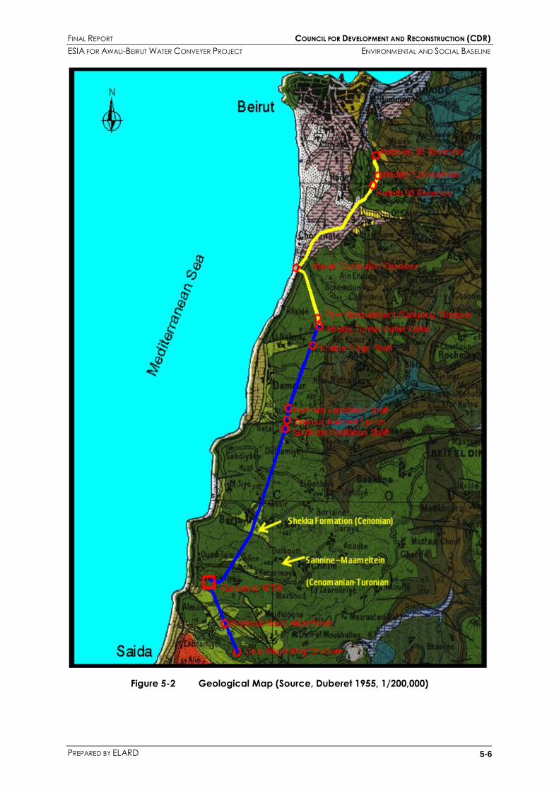
FINAL REPORT COUNCIL FOR DEVELOPMENT AND RECONSTRUCTION (CDR)
ESIA FOR AWALI-BEIRUT WATER CONVEYER PROJECT ENVIRONMENTAL AND SOCIAL BASELINE
PREPARED BY ELARD 5-6
Figure 5-2 Geological Map (Source, Duberet 1955, 1/200,000)

FINAL REPORT COUNCIL FOR DEVELOPMENT AND RECONSTRUCTION (CDR)
ESIA FOR AWALI-BEIRUT WATER CONVEYER PROJECT ENVIRONMENTAL AND SOCIAL BASELINE
PREPARED BY ELARD 5-7
5.5 WATER RESOURCES
The Sannine-Maameltein Formation is the major coastal aquifer in the study area. It is karstic in nature
with tertiary porosity meaning that groundwater is flowing mainly in fissures, fractures and conduits.
There are no permanent springs issuing from this formation except close to the coastal area and mainly
below sea level in the form of submarine springs (Feasibility Report, 1994).
The position of the water table is closely related to the base level which is the sea level and it gently
rises inland with a mean gradient of 11.5 m/km. The depth of the water table was determined from
groundwater wells (Feasibility Report, 1994).
It is believed that the proposed tunnel lays entirety in the vadose zone way above the water table.
However, water flowing from the surface in fractures, conduits, channels, caves and fracture zones is
likely to be encountered in more than one place along the tunnel with water discharging at a rate of
approximately 5 L/s (Feasibility Report, 1994). Dissolution cavities of up to 3 meters wide are also likely to
be encountered.
It is worth noting that dissolution and karstification in fractured zones along major and minor faults is
likely to be encountered during tunneling and this karstification has resulted in open and/or partially
filled large cavities with red clay and clayey sand.
Contaminated groundwater might also be possibly encountered during tunneling knowing that the
tunnel will pass underneath residential areas. Septic tanks are one of the possible sources of such
contamination. The tunnel also passes few kilometers down gradient from the Naame Landfill and
possible leaks from this landfill might be encountered during tunneling works.
This water quality has been addressed in 3.4 in the Project Description
5.6 LAND USE AND LANDSCAPE
The land use along the areas of the Awali project varies between the hills and the coastal planes. The
expansion of the coastal communities and the extension of the urban area from Beirut southwards also
affect the land use along the project areas.
Photographs in Appendix C have been provided to illustrate the nature of the landscape at the
locations of the various project elements.
The site of the Joun flow regulation structure lies at the side of a relatively steep valley. The only access
road that leads to the existing tunnel adit was done during former works for the already existing power
station tunnel. This road passes through terraced fields (some of which are used) and rough ground. An
old spoil heap also exists in the site below the adit from the previous works.
The Wadi Abou Yabes Washout site lies in an isolated hillside location. Large aggregates works with
associated polluting emissions are taking place at its lower end.
The proposed site for the Ouardaniye water treatment works lies in an open hillside location, gently
sloping to the west. It is formed of rough, stony ground with a small Wadi along the northern side.
There is no major residential activity in the site area but greenhouses are very common in and around
the site.
One frame for a house has been constructed at the site since this was first suggested as the site for the
water treatment works. The access road to the site will follow existing roads. The Wadi discharges into

FINAL REPORT COUNCIL FOR DEVELOPMENT AND RECONSTRUCTION (CDR)
ESIA FOR AWALI-BEIRUT WATER CONVEYER PROJECT ENVIRONMENTAL AND SOCIAL BASELINE
PREPARED BY ELARD 5-8
Ouardaniye bay on the Mediterranean coast. This bay has a wide sandy beach, with rocky headlands
to the north and south and it is popular for recreational activities, including bathing, with associated
facilities being provided.
The inverted Siphon at Damour will pass under a deep, narrow valley. The Damour washout site lies in a
very beautiful area in the valley, just next to the river where two restaurants and a picnic space are
situated. Access roads to the shafts will cross virgin wooded hillsides.
The Khalde surge shaft and outlet portal sites also consist of open rocky hillside sites having a steep
slope to the west. They lie adjacent to the new, high quality residential properties of some two to four
stories.
The pipeline route from the outlet portal starts with a regraded, existing road, and continues along the
side of the new coastal highway.
The Khalde flow distribution chamber will be constructed on a derelict site between the new highway
and the old coastal road. Offshore, the coastal beach is used for some recreational activities.
The pipelines from the Khalde flow measurement, distribution and connection chambers to the
proposed Hadath and Hazmieh reservoirs will pass from the old coast road to the main Chouwaifat
road uphill to the reservoirs. The first 2 Km of this path consist of a busy, dual carriage way. The
remaining part of the path consists of a standard width road. This path is surrounded by residential and
industrial properties along its sides for most of its length.
The proposed Hadath 125 reservoir site consists of a terraced sloping valley, bordered by new
apartment blocks to the north, a military barracks to the south, and a church and cemetery to the
west.
The proposed Hadath 90 reservoir site lies on waste ground to the west of the military barrack and to
the east of a tobacco manufacturing facility (REGI).
Further north the pipeline would pass through increasingly high class apartment residential blocks,
generally along dual carriageways width roads.
5.7 BIOLOGICAL ENVIRONMENT
Field visits for 12 sites along the tunnel path were conducted on the 13th and 21st of April 2010 to
conduct rapid ecological assessments Table 5-3. At each site, existing plant species were recorded
and documented in terms of their local and global significance.

FINAL REPORT COUNCIL FOR DEVELOPMENT AND RECONSTRUCTION (CDR)
ESIA FOR AWALI-BEIRUT WATER CONVEYER PROJECT ENVIRONMENTAL AND SOCIAL BASELINE
PREPARED BY ELARD 5-9
Table 5-3 Rapid Ecological Assessment Sites
NO LOCATION
1 Joun Regulation Structure
2 Washout – Wadi Abou Yabes
3 Ouardaniye WTW
4 Nahr Damour Siphon/Washout
5 Khalde Surge Shaft
6 Khalde Tunnel Portal
7 Khalde Flow measurement and sampling chamber
8 Pipeline – Khalde Portal to Khadle Flow Distribution Chamber
9 Khalde Distribution / Connection Chambers
10 Hadath 125 Reservoir
11 Hadath 90 Reservoir
12 Hazmieh 90 Reservoir
5.7.1 General Ecology
According to a study conducted by the Ministry of Environment (MoE, 1996), the 12 inspected sites are
within the Inferior Mediterranean or Thermomediterranean zones on a calcareous soil in the Carob-
Mastic series (for the majority of the sites), the Quercus calliprinos Webb. series (Nahr Damour
Siphon/Washout) and Pinus brutia Ten series for the Khalde Flow measurement and tunnel chamber.
The trees formation in the majority of the sites (Carob- Mastic series) take the form of garigues
composed mainly by Pistacia lentiscus L., Myrtus communis L., and less frequently by Ceratonia siliqua L.
This series is sometimes presented by Pinus halepensis Mill. and Pinus brutia Ten.
The first degradation stage of this series is composed by tall garigues dominated by Calicotome villosa
(Vahl) Link and in localized areas by Rhus tripartita (Ucria) D.C.
In areas that are more degraded, garigues of Poterium spinosum L. and Phlomis viscosa Poir. are
present in rocky places.
In Quercus calliprinos Webb. series, the tree formation is represented by Quercus calliprinos Webb. with
or without Pinus brutia Ten. In both cases Ceratonia siliqua L., Pistacia lentiscus L. and Myrtus communis
L. are relatively abundant.
In the Pinus brutia Ten series, the conifers Pinus brutia Ten., Pinus halepensis Mill. and Cupressus
sempervirens L. are the most abundant formation. Many other trees or shrubs are present. They include:
Gonocytisus pterocladus Boiss., Satureia thymbra L., Lygia aucheri (Meissn.) Boiss., Anarrhinum orientale
Benth., Cytisopsis dorycniifolia Jaub. et Spach. Etc.

FINAL REPORT COUNCIL FOR DEVELOPMENT AND RECONSTRUCTION (CDR)
ESIA FOR AWALI-BEIRUT WATER CONVEYER PROJECT ENVIRONMENTAL AND SOCIAL BASELINE
PREPARED BY ELARD 5-10
5.7.2 Sites Description
As a part of this Environmental Assessment, rapid ecological surveys were conducted at each site,
following the scoping exercise for the specific elements where surface activities are considered. The
identification of the species was done according to the “Nouvelle Flore du Liban et de la Syrie,
Mouterde” (1966, 1970, 1983).
In general, the different places of construction do not affect any area of special concern, such as
those designated as having national or international importance (e.g. world heritages, wetlands,
biosphere reserve, wildlife refuge, or protected areas), or lead to the extinction of endangered and
endemic species; However very important plant species were found in some sites. An inventory of the
species found was made site per site. The inventory listed only the species pertaining to this particular
ecological stage and whose habitat corresponds more or less to the local settings. Many of the
identified species are ornamental, medicinal or edible in nature.
It should be mentioned that this report was prepared after a visit to each site (13 or 21 of April 2010).
Therefore the information presented in this section should not be considered comprehensive and
exhaustive. However it provides a representative overview of the flora biodiversity in each site.
Joun Regulation Structure
At this site, a chamber (22m*10.5m) will be constructed. This site is small in size and located at the side
of a relatively steep valley. This site is very degraded, with very common species including Calicotome
villosa (Vahl) Link, Poterium spinosum L., Phlomis viscosa Poir., Nerium oleander L., Inula viscosa (L.)
Aiton, Echinops viscosus DC. and Notobasis syriaca (L.) Cass.
Nearby, Anchusa aegyptiaca (L.) DC. species were found. This is a relatively localized species in
Lebanon. No significant impacts on biodiversity are therefore expected at this site.
Photograph 5-1 Joun Regulation Structure Site
Washout – Wadi Abou Yabes
Wadi Abou Yabes is a hillside where a huge quarry is found. The project is therefore taking place in an
already significantly degraded environment.

FINAL REPORT COUNCIL FOR DEVELOPMENT AND RECONSTRUCTION (CDR)
ESIA FOR AWALI-BEIRUT WATER CONVEYER PROJECT ENVIRONMENTAL AND SOCIAL BASELINE
PREPARED BY ELARD 5-11
Photograph 5-2 Wadi Abou Yabes Washout Site
Ouardaniye WTW
This is the site where major construction works will take place. While the site can be generally described
as typical degraded garigues, several species were found and identified, including one specimen of
Rhus tripartita (Ucria) D.C. and one of Quercus calliprinos Webb, 5 species of orchids in large quantities
and many species of butterflies.
Given the variety of species found at this site, contractors should develop specific management plans
to minimize the impacts on these species. Further recommendations are provided as part of the EMP
Photograph 5-3 Ouardaniye WTW site
Some of the identified species found at this location include:
Ajuga chia Schreb., Allium neapolitanum Cyr., Allium trifoliatum Cyr., Anacamptis pyramidalis (L.) L. C.
Rich., Anagallis arvensis L. var. caerulea (L.) Gouan, Anagallis arvensis L. var. phoenicea Gouan,
Asparagus acutifolius L., Asphodelus microcarpus Salsm. & Viv., Briza maxima L., Calicotome villosa
(Vahl) Link, Campanula stellaris Boiss., Convolvus sp., Crataegus sp., Daucus carota L. subsp. maximus,
Eryngium creticum Lam., Filago arvensis L., Euphorbia thamnoides Boiss., Fumana thymifolia (L.) Spach,
Gladiolus segetum Ker-Gawler, Helichrysum sanguineum (L.) Kostel, Poterium spinosum L., Phlomis
viscosa Poir., Inula viscosa (L.) Aiton, Lactuca tuberosa Jacq., Micromeria myrtiflolia Boiss. et Hohen,
Notobasis syriaca (L.) Cass., Orchis sancta L., Orchis anatolica Boiss., Orchis coriophora L., Pallenis
spinosa (L.) Cass., Phagnalon rupestre (L.) DC., Phillirea media L., Pistacia palaestina Boiss., Pistacia
lentiscus L., Rhamnus punctata Boiss., Rhus tripartita (Ucria) D.C., Ricotia lunaria (L.) D.C., Serapias
vomeracea (Burm.) Briquet, Smilax aspera L., Stachys arvensis (L.) L., Stachys neurocalycina Boiss.,
Stachys distans Benth., Tamus communis L., Teucrium divaricatum Sieb. ex Heldr. subsp. villosum (Celak.)

FINAL REPORT COUNCIL FOR DEVELOPMENT AND RECONSTRUCTION (CDR)
ESIA FOR AWALI-BEIRUT WATER CONVEYER PROJECT ENVIRONMENTAL AND SOCIAL BASELINE
PREPARED BY ELARD 5-12
Rech. fil, Teucrium polium L., Tragopogon longirostris Bisch. Ex Schultz Bip., Quercus calliprinos Webb
and Verbascum sp.
Nahr Damour Siphon/Washout
Photograph 5-4 Nahr Damour Siphon/Washout Site
The Damour Valley ecosystem has a rich variety of flora. In the river crossing at the selected site,
several types of vegetation cover composed mainly by Platanus orientalis L. (Oriental Plane), Alnus
orientalis Decne (Oriental Alder), Acer syriacum Boiss. et Gaill. (Syrian Maple), Pistacia lentiscus L.
(Mastic), Pistacia palaestina Boiss. (Wild Pistachio), Quercus sp. (Oak), Salix acmophylla Boiss. and Salix
alba L. var. micans And. (Willow) were found.
As seen on the maps, the inverted siphon at Damour will pass under a deep, narrow wooded valley
and the construction will take place in a relatively small area of the site.
During the site visit, only red highlighted areas in the figure were inspected; the owner of the restaurant
did not allow any access to the green section. The red area was much degraded; cement was
covering a large surface of the area and many cultivated trees and shrubs (Citrus, Eucalyptus, Melia
azederach, Punica granatum, Schinus molle, Hibiscus rosa sinensis) were planted. Many parasitic
(Orobanche) plants and the invasive Ailanthus altissima (Mill.) Swingle were found in this location.
Even though the sanded(?) area was very much degraded (mainly because of the restaurants), other
cultivated plants were found like Mirabilis jalapa L. Another interesting finding in this spot was what
could be the endemic Melissa inodora Bornm (There was no flower to be positively sure).
Unfortunately and as mentioned above, the green area could not be inspected. It consists of an old
bridge surrounded by many types of vegetation cover. Apparently the restaurant owner is using the
place under the bridge to provide some intimacy to special clients. According to the maps, this area
will be protected from any construction. As mentioned earlier in this report, a small area of this site will
be affected by construction. However special considerations should be taken by contractors to
minimize negative impacts while providing benefits to the area. For example, indigenous trees can be
planted and the alien species (cultivated trees and plants) can be removed, positively affecting the
ecology and ecosystems of this area.

FINAL REPORT COUNCIL FOR DEVELOPMENT AND RECONSTRUCTION (CDR)
ESIA FOR AWALI-BEIRUT WATER CONVEYER PROJECT ENVIRONMENTAL AND SOCIAL BASELINE
PREPARED BY ELARD 5-13

FINAL REPORT COUNCIL FOR DEVELOPMENT AND RECONSTRUCTION (CDR)
ESIA FOR AWALI-BEIRUT WATER CONVEYER PROJECT ENVIRONMENTAL AND SOCIAL BASELINE
PREPARED BY ELARD 5-14
At a distance of the Damour Valley, the 2 Washout locations that will be connected with the Damour
location were inspected. The first one (left picture 14) is a degraded land with no important impact on
the environment. The second location (right picture 15) a typical dense forest was found with very rich
tree vegetation. The entrance to this forest was difficult mainly because of the trees, but the following
trees and shrubs were identified: Phillirea media L., Calicotome villosa (Vahl) Link, Pistacia palaestina
Boiss., Rhamnus punctata Boiss., Rhamnus alaternus L., Quercus calliprinos Webb., Acer syriacum Boiss.
et Gaill., Ceratonia siliqua L., Arbutus andrachne L., Pistacia lentiscus L., Myrtus communis L., Ruscus
aculeatus L., Salvia fruticosa Mill., Cistus creticus L. and Cistus salviifolius L.
Even though no major construction in this location is planned, the contractor should be careful in the
set up phase and special care should be taken to avoid impacts to the trees
Photograph 5-5 Nahr Damour Washout
Site
Photograph 5-6 Nahr Damour Washout Site
Khalde Flow measurement and sampling chamber (site 7)
This was by far the most important ecosystem visited among the 12 selected sites. This site is on the Pinus
brutia Ten series, where the conifers Pinus brutia Ten., Pinus halepensis Mill. and Cupressus sempervirens
L. are the most abundant formation.
This location is characterized by the richness of its flora and the aged specimens of the trees found.
Contractors should prepare a management plan in a way to protect these species and minimize the
number of species directly affected by the construction works, even though construction footprint at
this location is relatively small.

FINAL REPORT COUNCIL FOR DEVELOPMENT AND RECONSTRUCTION (CDR)
ESIA FOR AWALI-BEIRUT WATER CONVEYER PROJECT ENVIRONMENTAL AND SOCIAL BASELINE
PREPARED BY ELARD 5-15
The trees, shrubs and plants found at this site were mainly:
Pinus brutia Ten., Pinus halepensis Mill., Quercus sp., Pistacia palaestina Boiss., Rhamnus punctata Boiss.,
Rhamnus alaternus L., Ceratonia siliqua L., Pyrus sp., Phillirea media L., Calicotome villosa (Vahl) Link,
Salvia fruticosa Mill., Cistus creticus L., Cistus salviifolius L., Satureia thymbra L., Cytisopsis dorycniifolia
Jaub. et Spach., Ononis hirta Desf., Serapias vomeracea (Burm.) Briquet, Centaurium erythraea Refn.,
Ophrys apifera Hudson., Gladiolus segetum Ker-Gawler, Stachys neurocalycina Boiss., and Stachys
distans Benth.
As for the remaining sites (Khalde Surge Shaft, Khalde Tunnel Portal, Pipeline – Khalde Portal to Khadle
Flow Distribution Chamber, Khalde Distribution / Connection Chambers, Hadath 125 Reservoir, Hadath
90 Reservoir and Hazmieh 90 Reservoir), all are highly degraded and/or with no important floral
biodiversity. Most of them are located in urban areas with limited biodiversity.
Photograph 5-7 Remaining Sites

FINAL REPORT COUNCIL FOR DEVELOPMENT AND RECONSTRUCTION (CDR)
ESIA FOR AWALI-BEIRUT WATER CONVEYER PROJECT ENVIRONMENTAL AND SOCIAL BASELINE
PREPARED BY ELARD 5-16
5.8 CULTURAL HERITAGE
A study was commissioned to determine the extent of the archeological sensitivity of the project area
during the old EIA study. Particular concerns had been noted in the Khalde and Chouwaifat areas
where the research and work was concentrated. It involved a review of published and unpublished
archeological material, a brief physical survey of the area and interviews with local inhabitants. The
following findings can be highlighted:
In the Joun and Ouardaniye areas, there are no known archeological or historical interests, as
would be expected in these rocky localities far from known former habitation.
At the Damour River crossing, there are also no known archeological remains, and no pottery
shards have been found there. The tunnel will be located downstream of the meeting of two
waters, historically a tourist location.
The most significant known archeological site is the Khan in Khalde area, located along the
coast by the end of the runway extension for Beirut airport. Much of the khan has been
destroyed by the urban development occurring in the area and the construction of the coastal
highway.
Three phases of occupation have been identified at this site – classical (Greco Byzantine),
Phoenician and Bronze Age.
To the west of the pipeline, occurs an extensive necropolis area that contains numerous tombs,
related houses, baths and associated facilities.
To the south of the pipeline route in Khalde is a byzantine religious complex, and there are
rumors of possible other former settlement in this area. There is no evidence of archeological
remains along the Khalde to Chouwaifat pipeline route, and this is confirmed by local
anecdotal talks.
If these areas are linked, then there is the possibility that classical remains could be found along
the pipeline route near the coast. However, the former housing and road construction in the
area would have destroyed most such remains (if they existed), and no evidence of
archeological remains was encountered in the trial pit dug in this area for the geotechnical
investigation for this project. It is concluded that this specific area contains little of
archeological interest.
At the Hadath 125 Reservoir site, cemeteries are situated to the west, across the local road.
There are no known archeological interests at the other reservoir sites or adjacent to the
connecting pipeline routes.
5.9 SOCIO ECONOMIC ENVIRONMENT
A socio-economic survey was conducted with the local authorities in the Project area to map the
demographic, social and economic baseline conditions at the level of towns and villages. This
document also seeks to identify how the Project‟s potential impacts might affect the identified baseline
conditions. In other terms, the purpose of the study of socio-economic baseline conditions is to present
a basis against which potential socio-economic impacts (whether positive or negative), induced during
and as a direct or indirect result of the Project activities, can be assessed.
Data for this section was collected through:
(1) a desk review and consolidation of publicly available information from previous reports and the
Ministry of Interior and Municipalities‟ web portal on villages,

FINAL REPORT COUNCIL FOR DEVELOPMENT AND RECONSTRUCTION (CDR)
ESIA FOR AWALI-BEIRUT WATER CONVEYER PROJECT ENVIRONMENTAL AND SOCIAL BASELINE
PREPARED BY ELARD 5-17
(2) individual face to face interviews with local, elected leaders and stakeholders to corroborate
and supplement the desk review findings. The interviews were held with stakeholders in the
towns and villages which will feature construction works, whether for supply, storage and/or
distribution within the Awali–Beirut Water Conveyor Project,
(3) an intercept, random, researcher-administered survey with land operators, where main surface
structures will be constructed and whose lands will be expropriated accordingly, in order to
collect general information on their perceptions of the Project components and planned
outcomes, and
(4) a site walk-over along the planned pipeline through Khaldeh, Hadath and Hazmieh.
The tools used for collecting data for the field survey included questionnaire sheets with structured
questions for the interviews and land operator surveys, and photo shooting for visual documentation of
the visited sites.
During the surveying of local leaders and residents, data was collected on: (1) the locality‟s
demographic profile including age and gender distribution; (2) the availability of public and private
educational institutions and the overall level of education; (3) land ownership and land use patterns; (4)
socio-cultural practices; (5) livelihood and income-generating activities in agriculture, agro-food
businesses and industries, as well as industrial and commercial activities; (6) existing physical, public
infrastructures, resources and services, e.g. water supply sources and networks, power supply,
telecommunications, roads, sewage and solid waste disposal practices; and (7) development needs
and priorities relating to poverty, unemployment, sanitation, etc. Individual consent was sought prior to
any field data collection.
Furthermore, ELARD prepared and distributed a flyer (see Appendix H) that summarises the Project and
informs the resident population and stakeholders of the public consultation session. The public
consultation event was held on 12 May 2010. The issues raised in the public consultation are detailed in
Appendix I.
It should be noted that due to the lack of formal, comprehensive and consistent data collection and
record keeping processes on part of the interviewees, any figures contained within this socio-economic
baseline section should be regarded as estimates.
5.9.1.1 Areas relevant to the socio-economic assessment
The geographical scope of this assessment includes the areas that are directly affected by this Project
through the sub-surface and surface structures that will be constructed underneath or in the villages.
A standard survey instrument was developed to collect information of relevance to the socio-economic
assessment at the community level, especially with regard to livelihoods and standards of living
The study area is classified into two levels of concern:
1. The primary level which includes those villages and towns in which main surface structures are
constructed. These are summarized in Table 5-4

FINAL REPORT COUNCIL FOR DEVELOPMENT AND RECONSTRUCTION (CDR)
ESIA FOR AWALI-BEIRUT WATER CONVEYER PROJECT ENVIRONMENTAL AND SOCIAL BASELINE
PREPARED BY ELARD 5-18
Table 5-4 Villages, towns and surface structures
VILLAGE/TOWN SURFACE STRUCTURE PLANNED IN THE VILLAGE/TOWN
JOUN REGULATING STRUCTURE
WADI ABOU YABES WASHOUT
OUARDANIYE TREATMENT WORKS
DAMOUR AREA TWO VENTILATION SHAFTS AND INVERTED SIPHON
NAAMEH RESERVOIR
KHALDEH
FLOW MEASUREMENT AND SAMPLING CHAMBER
SURGE SHAFT
OUTLET DISTRIBUTION CHAMBER
CHOUEIFAT RESERVOIR
ARAMOUN EL-GHARB N/A
BSOUS N/A
KFARCHIMA RESERVOIR
HADATH TWO RESERVOIRS
WASHOUT
WADI CHAHROUR RESERVOIR
BAABDA (INCL. BAABDA, EL FAYYADIYEH,
EL YARZEH, EL LOUAIZEH) RESERVOIR
HAZMIYEH ONE RESERVOIR
AL CHIAH N/A
BOURJ EL BARAJNEH N/A
HARET HREIK N/A

FINAL REPORT COUNCIL FOR DEVELOPMENT AND RECONSTRUCTION (CDR)
ESIA FOR AWALI-BEIRUT WATER CONVEYER PROJECT ENVIRONMENTAL AND SOCIAL BASELINE
PREPARED BY ELARD 5-19
The secondary level includes those villages and towns that are crossed by the tunnel. These villages are
listed in Table 5-5.
Table 5-5 Villages and towns crossed by the tunnel
English name Arabic name District
Saraouniye صروويت Chouf
Mazraat El Barghoutiye مسرعت البرغىثيت Chouf
Sabonieh صابىويت Chouf
Jamailiye الجميليت Chouf
Wardaniye الىرداويت Chouf
Sibline سبليه Chouf
Maaniye معىيت Chouf
Ain El Assad عيه األسد Chouf
Barja برجا Chouf
Marj Barja مرج برجا Chouf
Ras Aalous راش علىش Chouf
Baasir بعاصير Chouf
Dabche دبشت Chouf
Haret Baasir حارة بعاصير Chouf
Halioune El Tahta حليىوي التحتا Chouf
Halioune El Faouqa حليىوي الفىقا Chouf
Baqoun بقعىن Chouf
Dahr El Mgara ضهر المغارة Chouf
Aaqline عقليه Chouf
Mazraat Er Rzaniye مسرعت الرزاويت Chouf
Daher El Aaqline ضهر العقليه Chouf
Mghaireh مغيري Chouf
Lahbiyeh الهبيت Chouf
Mechref المشرف Chouf
Baawerta بعىرته Aley
Haret Chbeib حارة شبيب Aley
Khaldeh خلدة Aley
Hadath الحدث Baabda
Hazmiyeh الحازميت Baabda
5.9.1.2 Description of the demographic structure
The Project‟s phases fall entirely within the Mount Lebanon Governorate and across three Districts
(Caza) – Chouf, Aley and Baabda. The project extends from the village of Joun where water is
abstracted and delivered to three reservoirs located in the urban settlements of Hadath and Hazmieh.
An extensive distribution network is planned to be constructed in the GBA to deliver the reservoirs‟ water
to the heavily-urbanised Beirut suburbs. Smaller reservoirs are planned to be constructed as part of the
main distribution network. These reservoirs will be located in Naameh, Aramoun El-Gharb, Choueifat,
Bsous, Kfarchima, Bourj El Barajneh, Al Chiah, Haret Hreik, Hazmiyeh, Baabda and Wadai Chahrour.

FINAL REPORT COUNCIL FOR DEVELOPMENT AND RECONSTRUCTION (CDR)
ESIA FOR AWALI-BEIRUT WATER CONVEYER PROJECT ENVIRONMENTAL AND SOCIAL BASELINE
PREPARED BY ELARD 5-20
The areas crossed by the project are either rural or heavily urbanised. There are no accurate
quantitative data on the demographic and socio-economic structures in the villages and towns where
structures are due to be erected. However, a general profile of the whole Mount Lebanon governorate
is summarized in Table 5-6 to give the reader a general idea about the profile of the area.
Table 5-6 Demographic and socio-economic characteristics of communities in Mount
Lebanon
3 CAS, “The National Survey of Household Living Conditions” (The Multi-purpose Survey), 2004 4 Raw Data MoSA, CAS, UNDP, 2006a 5 CAS, “The National Survey of Household Living Conditions” (The Multi-purpose Survey), 2004
6 CAS- The National Survey of household living conditions - 2007
7 UNDP- National Human Development Report – 2008-2009 8 “Millennium Development Report”, Lebanon, 2003
GOVERNORATE OF MOUNT LEBANON
Percentage distribution of the population by gender (2004)3
Male 50.7
Female 49.3
Fertility rate 2 children
Illiteracy rate4
Male 4.5%
Female 1.48%
Total 7.51%
Education enrollment rate by age5
5-9 98.1
10-14 96.5
15-19 76.9
20-24 39.0
25-29 6.7
Percentage distribution of actual labour force (≥15 years) by economic
sector6
Agriculture 1.8
Industry 16.3
Construction 5.1
Trade 23.2
Transportation, post &
telecommunications 7.3
Services 43.3
Insurance; Monetary and
financial intermediation 2.9
Long-term unemployment as % of
actual labour force7 2.8%
Women‟s health care during
pregnancy (in 2000)8 98.4%

FINAL REPORT COUNCIL FOR DEVELOPMENT AND RECONSTRUCTION (CDR)
ESIA FOR AWALI-BEIRUT WATER CONVEYER PROJECT ENVIRONMENTAL AND SOCIAL BASELINE
PREPARED BY ELARD 5-21
5.9.1.3 General findings on development needs
Interviews with the local authority representatives on the general socio-economic and livelihood
conditions revealed the extent of weakness in the infrastructure that provides water services to residents
in parts of the Chouf, Aaley and Baabda districts. On the overall, the sources of water for drinking,
service and irrigation purposes were varied, managed by different parties and did not meet the
consumption needs of residents. There is a proliferation of private wells and municipality-owned wells
that are used to supplement the intermittent water supply from water authorities. The depths of these
wells reach 400 m in some areas. Water distribution networks are in a poor condition. Some
municipalities have initiated repairs and installed new networks, but those remain the exception.
Wastewater networks are present in the area; however the coverage is not universal. A small
percentage (~30%) of households is not connected and continues to dispose of sewage in uncontrolled
septic tanks.
With the exception of the agricultural areas of Iqlim El Kharroub in the Chouf district and in the coastal
agricultural plains of the Damour and Naameh, agriculture in the study area is on the wane. Water for
agriculture is sourced from springs and private wells, as well as from the Damour River. It is well-
documented however that the coastal aquifers are witnessing increasing salinity. Another, equally if not
more important, pressure on agriculture is the urban expansion and a boom in construction in the hills
overlooking Beirut from the south and the flat areas in the southern suburbs leading to fewer agricultural
lands and non-built areas.
A rise in the standard of living and increasing population density place higher demands on the public
infrastructure and utility provision. Water shortages in these areas are commonplace, and the
population continues to adapt by tapping private sources, e.g. private wells. On the other hand, and
due to the block pricing system of water, households continue to pay for a largely unmet service,
whereby a subscriber annually pays for a 1m3/day provision, however water flows only 2-3 days/week
on average.
These general findings were concluded upon an investigation of the livelihoods and public infrastructure
in the villages and towns where the Awali-Beirut Water Conveyor will cross and/or deliver water through
small reservoirs. Although the project was first intended to deliver the Awali water to the southern
suburbs directly adjacent to Beirut, its planners have recognised that water shortages in the coastal
villages of Iqlim El Kharroub necessitate allowing for the abstraction of water from the tunnel to supply
those villages. Within the Project‟s second phase, small reservoirs are planned to be built to provide a
direct supply to the villages and their neighbouring localities. However, the weakness of distribution
infrastructure and lack of fully-functional sanitation services may delay or dampen the anticipated
benefits of augmented supplies.
5.9.1.4 Findings by village
The surveys and meetings conducted in the Project study area serve to provide a general overview of
the socio-economic situation in the localities which will host the Project‟s infrastructure. The survey
instrument used to hold structured interviews with local leaders and authority representatives is included
in Appendix G. The demographic and socio-economic characteristics and features of the ‘primary
level’ villages with planned surface infrastructure are portrayed below. Table 5-7 shows a general

FINAL REPORT COUNCIL FOR DEVELOPMENT AND RECONSTRUCTION (CDR)
ESIA FOR AWALI-BEIRUT WATER CONVEYER PROJECT ENVIRONMENTAL AND SOCIAL BASELINE
PREPARED BY ELARD 5-22
description of the villages, including information on the educational infrastructure, socio-cultural
attributes and water and wastewater services.
Joun
Joun village lies within the district of Al-Chouf at 350-400m above sea level and over an area of 12 km29.
It boasts a culturally and religiously diverse community, a high literacy rate among its population and a
functioning local authority. General information on Joun can be found in Table 5-7. Specific
information on the area where the regulating structure will be erected is listed in Table 5-8. The
regulating structure is planned to be sited close to the Monastery Saint Saviour, which also operates an
adjoining high school, and close to the Damco Company, a producer of concrete building blocks. A
staff member of the Damco Co reported that the manufacturer abstracts water from a nearby spring
and uses septic tanks for sewage disposal.
In the Project‟s EIA, completed in 1998, the Ministry of Environment raised questions on the impact of
water abstraction on the operation of the Joun hydroelectric power plant and the resultant changes in
the delivery of irrigation water to Joun‟s agricultural areas (see Appendix B). This concern was also
raised at the public participation meeting on May 12, 2010.
A water flow of 3m3/s (out of an average flow of 25m3/s) upstream the Joun hydroelectric power plant
and into the planned tunnel is to be conveyed to Beirut. The diverted amount will not reduce the
power generation at the plant because this amount of water is a surplus, owing to the fact that initial
plans at the time of the plant‟s design and construction had accounted for this future diversion.
A walk-over survey of the lands and structures downstream of the Joun hydroelectric power plant was
conducted and interviews with river bank restaurant owners were held. The River‟s water downstream is
used to irrigate the agricultural lands adjacent to the river. The restaurants‟ operators did not foresee
any impacts on their industry from reduced water flow in the River, given that the height of water in the
river could reach 3 or 4 m.
The land ownership in the area is yet to be identified through a land survey to be carried out at a
future date.
Wadi Abou Yabes
The washout structure at Wadi Abou Yabes is located on the outskirts of the towns of Jamailiyeh and
Sabouniyeh. The nearest activity taking place is a stone quarry site and its associated building blocks
factory. The quarry site and plant obtain their water through a private well, drilled at a depth of 65 m,
to supply 30-45 m3 of water daily. The future location of the washout structure in Wadi Abou Yabes and
the nearby quarry site are shown in Appendix B and detailed in Table 5-8. Information on the village of
Jamailiyeh appears in Table 5-7.
Ouardaniye
Ouardaniye falls within Iqlim Al-Kharoub of Al-Chouf District. The structures for the Ouardaniye Water
Treatment Works will be located on the outskirts of the towns of Ouardaniye and Sibline, in the vicinity of
agricultural plots within the jurisdiction of Ouardaniye and overlooking the Sibline cement factory (see
9 Bou Maroun, P.M. “Joun: Bride of the Iqlim surrounded by the Awali Waters and an Orange Blossom Fragrance.”
Lebanese Army Magazine, Issue 239, May 2005. In Arabic.

FINAL REPORT COUNCIL FOR DEVELOPMENT AND RECONSTRUCTION (CDR)
ESIA FOR AWALI-BEIRUT WATER CONVEYER PROJECT ENVIRONMENTAL AND SOCIAL BASELINE
PREPARED BY ELARD 5-23
Appendix B). All of the land lots directly affected by the project are privately owned except for one
plot (No. 561-560) which is publicly owned by the State.
The number of residents in Ouardaniye is about 4,000 living in small cement buildings of 1-3 floors. The
employment rate is high. Agriculture activities mainly take place in greenhouses where tomato is the
main crop, accounting for nearly 5-6% of the region‟s income. No common diseases were recorded in
the village. General information on the Ouardaniye and Sibline villages are presented in Table 5-7.
Regarding the infrastructure, all roads are paved and electricity is available through the national grid.
The town of Ouardaniye is not served by a sewage network and disposes of its wastewater in septic
tanks.
Contrary to the situation that prevailed in 1998 and which was highlighted in the previous EIA, whereby
an adequate water distribution network was missing, today two water wells found at a depth of 452 m
and 369 m10 respectively are used as the main water supply sources. The municipality distributes 1000
m3 of water per day via a network according to a specific schedule. In addition to this „official‟ water
network, up to 150 private wells used for private consumption are drilled in the village.
The municipality has a pending request, submitted in 2005, for the designation of a protected area
within the jurisdiction of Ouardaniye.
Al-Damour
Al-Damour is a large town of 30,000 registered inhabitants, but only one-third of the town‟s „citizens‟ are
residents, while only 1,000 households are occupied around the year, due to the displacement of
residents during the civil war and high emigration rate to urban centers. The town area extends from the
Damour agricultural plains on the coast up to the mountains and deep valleys through which the
Damour River runs. A fifth of the town‟s lands are agricultural with a total of 100 ha of cultivated areas –
mostly bananas and vegetables, which are irrigated from the River and municipality-owned wells. The
town‟s drinking and service water is derived from municipality-owned and managed wells, as well as
from private wells. A ventilation shaft is planned to be constructed to the south of the Damour River, in
an uninhabited area (see Appendix C). The mountains and valleys of Damour are touristic areas, with
restaurants and cafés scattered on the river banks. Further north to the ventilation shaft, a washout will
be constructed close to some of the restaurants. The owner of one of the restaurants reported the lack
of water and wastewater networks and the presence of four lined septic tanks at a 3m depth in the
restaurant‟s premises. Most of the lands are privately owned. General information on Al-Damour is
presented in Table 5-7.
Mechref
Mechref village is located north of Al-Damour and the Damour River and lies within the district of Al-
Chouf. It is regarded as a resort town with holiday homes. The main surface structure to lie within the
village boundaries will be a ventilation shaft south of the village and far from currently inhabited areas
(See Appendix C). Sub-surface structures will be passing right underneath the village. Land use, land
ownership and water infrastructure are issues that are yet to be examined in the Mechref village.
10 Their coordinates being (N 33° 36' 46.1", E 35° 26' 29.0") (N 33° 36' 56.2", E35° 26' 18.0").

FINAL REPORT COUNCIL FOR DEVELOPMENT AND RECONSTRUCTION (CDR)
ESIA FOR AWALI-BEIRUT WATER CONVEYER PROJECT ENVIRONMENTAL AND SOCIAL BASELINE
PREPARED BY ELARD 5-24
Naameh
Naameh lies within the district of Al-Chouf at an altitude of 100m above sea level. The majority of lands
(98%) are privately owned and the rest are owned by the municipality. The village is witnessing a
construction boom whereby 150-200 building permits were handed out in the last three years. Currently
there are 26,000 residents in Naameh. Agriculture is practiced on 30% of the land in Naameh. The
major agricultural crops grown are vegetables, bananas and strawberries. Irrigation water is supplied
from the Damour River and from private wells. Most crops are irrigated using the drip technique;
meanwhile bananas are surface-irrigated.
Drinking and service water are supplied through Ain El Delbeh water authority, the Mechref wells
operated by the Beirut and Mount Lebanon Water and Wastewater Establishment, private wells and a
municipality well. Despite the variety of sources, the village reports a shortage in water. The majority of
households (80%) receive their water through a distribution network, which is however in a poor state.
The majority of households (70%) are connected to the sewage network.
Khaldeh
Khaldeh, which is considered as a residential and touristic area, falls under the jurisdiction of the
municipality of Choueifat in the Aley District. It is a coastal area that is rapidly urbanizing with 15,000-
20,000 residents living in cement buildings of 1-4 floors.
All the land lots which are directly affected by the project are privately owned and the village is well-
serviced with paved roads. A water distribution network runs through Khaldeh and is supplied from the
Mechref village. According to the head of the Choueifat municipality, the water pipes have all been
repaired this year. Also, several privately drilled wells exist in the village with a depth ranging from 30-60
m but water is slightly salty. Furthermore a sewer network is present and is connected to the collector in
Khaldeh. No common diseases were recorded in the area.
Khaldeh will be the site of several surface structures: a measurement and sampling chamber, a surge
shaft and a distribution chamber. The first two structures will be located near residences, and the land
ownership has to be determined. The distribution chamber will be located in a vacant land plot near
the highway (see Appendix C).
The head of the Choueifat municipality strongly opposed the Project for the following reasons:
As mentioned above, the water pipes have all been repaired this year and the costs incurred
were high. The municipality will not accept any errors that could damage the newly installed
pipes.
The land is rocky and it would be too difficult to pass pipelines or tunnels through it.
The idea of getting water from South Lebanon is not favourable and it would be preferable to
get if from Al-Kaleb River or to drill wells. He also proposed to establish desalination stations or to
even recycle water.
The old Saida road suffered from the density of ground-based extensions of different types and
will not tolerate any more pipelines.
FINAL REPORT COUNCIL FOR DEVELOPMENT AND RECONSTRUCTION (CDR)
ESIA FOR AWALI-BEIRUT WATER CONVEYER PROJECT ENVIRONMENTAL AND SOCIAL BASELINE
PREPARED BY ELARD 5-25
Choueifat
Choueifat is a large urban town of 200,000 residents, spreading over 18 sq. km. It is also witnessing a
boom in construction, where an average of six building permits are authorised every month (over 200
permits in the last three years). Irrigation water for the little remaining agricultural lands is supplied from
springs and private wells. Water in the town is supplied through a municipality well and five public wells
operated by the Ain el Delbeh water authority, whose depths range from 30 to 200 m.
Aramoun El-Gharb
Aramoun lies in the district of Aley at 450m altitude. It is a predominantly residential village with 4,000
household units and 16,000 permanent residents. The village has rapidly grown in the past decade. In
the last three years, 120 building permits were approved. The water supplied to the village is sourced
from springs and a municipality well located at a 400m depth, in addition to a small amount from the
Barouk water authority. The village faces shortages in water, whereby water is supplied for 12 hours per
week. The existing water distribution network is in a poor state and does not reach all households. The
majority of households are connected to a sewage network, which however is in a state of disrepair.
Bsous
Bsous is a rural village in the district of Aley situated at an altitude of 450m above sea level. One-third of
the land is used for agricultural purposes, another third is forested land and the remaining areas are
built-up. The small village of 2.5 sq. km counts 600 household units, 3,000 permanent residents and 5,500
residents during the summer months. Agricultural areas mostly consist of olive and almond orchards
which are irrigated from harvested rain water through drip and surface irrigation.
Drinking and service water are supplied through a public well that is operated and managed by the
water authority, and distributed through a well-maintained distribution network on a daily basis. The
village is serviced a wastewater collection network covering 75% of the households. The remaining
households retain septic tanks for sewage disposal.
Kfarchima
Kfarchima is a semi-urban locality located in the district of Baabda between 100 and 250 m above sea
level and covering a land surface of 5 sq. km. Half of the land consists of built-up areas, and the rest are
divided equally among agricultural areas and natural areas consisting mostly of forests. The resident
population is estimated at around 20,000 occupying 2,000 household units. The municipality of
Kfarchima reports approving only 30 building permits in the past three years. The agricultural lands in
Kfarchima are used for growing vegetables and as olive orchards, and are irrigated from the local
spring through drip and surface irrigation techniques. The Ain El Delbeh Water Authority operates two
wells in Kfarchima and the water is conveyed to the residents by gravity and pumping through an aging
distribution network that has been recently replaced by a newer one, which however has not yet been
put in service. The village is served by an old wastewater collection network that is in a poor state.
Hadath
Hadath is a large urban centre lying in the Baabda District between 50 and 300 m above sea level and
covering an area of 5.5 sq. km. It counted 150,000 residents in 2002. Its low-lying areas are considered
an extension of the southern suburbs of Beirut. The area has witnessed a very rapid growth in newly built

FINAL REPORT COUNCIL FOR DEVELOPMENT AND RECONSTRUCTION (CDR)
ESIA FOR AWALI-BEIRUT WATER CONVEYER PROJECT ENVIRONMENTAL AND SOCIAL BASELINE
PREPARED BY ELARD 5-26
areas and a concentration of new businesses. It is primarily a residential and commercial town with
some light industrial activity. It is home to many public service institutions, is well-developed and well-
serviced through road networks. General information on the town of Hadath appears in Table 5-7.
The town of Hadath is served through a municipality-owned and managed water distribution network.
The town receives its water supply from the Ain El-Delbeh Water Authority. It is also served by a
wastewater network.
Hadath will be the home of two reservoirs (see Appendix C). Both reservoirs lie in sparsely populated
areas; however, there are residences that are very close to the planned site of the new structures.
Baabda
Baabda is the Baabda‟s District centre town. It has a permanent resident population of 40,000 and
7,000 household units. The neighbourhoods of Fayyadiyeh, Louaizeh and Yarzeh fall under the authority
of the Baabda municipality. These areas are highly sought by property developers due to their
proximity to Beirut and their relatively secluded location. The Baabda municipality handed out 300
building permits in the last three years. Water is supplied from the Ain El Delbeh Water Authority as well
as from a well in Yarzeh that is operated by the Baabda municipality and is 350m deep. All households
were reported to be connected to the sources through a distribution network of average quality. The
majority of households are connected to the wastewater network.
Hazmieh
Hazmieh is a large urban area next to Hadath lying between 50 and 150 m above sea level over 3.05
sq. km. It has a resident population of 40,000 occupying 8,000 household units. Similar to Hadath, it is a
rapidly urbanizing area that is home to several public service institutions – such as the Ministry of Public
Works. It counts 6,500 residents and has a strong presence of bank branches (over 10 bank branches).
Its drinking and service water are supplied from the Spring of Daichouniyeh through the Ain El-Delbeh
Water Authority and distributed through a public network to all residents at a rate of 2-3 days per week.
The local authority representative, who was interviewed, reported quality problems and shortages in the
summer season. Hazmieh is served by a wastewater network. General information on the town of
Hazmieh is shown in Table 5-7.
A reservoir is planned to be built in Hazmieh in a vacant land plot (Appendix C). The land ownership
and designated land use have yet to be determined.
Chiah
Chiah is an urban locality with a high population density. Water is supplied to the estimated 7,000
household units from the Ain El Delbeh Water Authority sources. Residents do not consider the water of
drinking quality and prefer to buy bottled water for drinking purposes. All households are connected to
the distribution network which is reported to be in an average condition. All households are also
connected to the wastewater collection network.
Bourj El Barajneh
Bourj El Barajneh is a densely populated suburb right outside the city of Beirut. A total resident
population of 250,000 inhabitants dwell in 35,000 units built over 5 sq. km. Built areas take up 90% of all
the land area. Nevertheless, the municipality handed out 55 new building permits in the last three

FINAL REPORT COUNCIL FOR DEVELOPMENT AND RECONSTRUCTION (CDR)
ESIA FOR AWALI-BEIRUT WATER CONVEYER PROJECT ENVIRONMENTAL AND SOCIAL BASELINE
PREPARED BY ELARD 5-27
years. Sparse agricultural lands can still be found with vegetables grown. Water is provided through the
Ain El Delbeh Water Authority sources, private wells and through private haulers to households,
especially for drinking water. A well-maintaind distribution network connects the public water sources
to all residents. The area is also served by a well-maintained sewage collection network.
Haret Hreik
Haret Hreik is another heavily urbanised, densely populated suburb to the south of the city of Beirut
covering less than 2 sq. km. Yet, it counts 25,000 household units occupied by more than 100,000
residents. It is served by the Ain El Delbeh Water Authority and receives its water from the Spring of
Daichouniyeh and private wells. A distribution network is present; however it is in a poor state and
covers only 10% of households. Wastewater and storm water networks are present and provide
coverage to all households and roads.

FINAL REPORT COUNCIL FOR DEVELOPMENT AND RECONSTRUCTION (CDR)
ESIA FOR AWALI-BEIRUT WATER CONVEYER PROJECT ENVIRONMENTAL AND SOCIAL BASELINE
PREPARED BY ELARD 5-28
Table 5-7 General features of surveyed towns and villages
VILLAGE/
TOWN GENERAL DESCRIPTION LIVELIHOOD ACTIVITIES
EDUCATION, CULTURE, COMMUNITY &
PUBLIC INFRASTRUCTURE WATER & WASTEWATER SERVICES
OTHER
INFORMATION
Joun
Population: 7500-8000
Altitude: 350-400 m
Surface area: 12 km2
Land ownership: 20-30%
publicly owned, and the
remaining is privately
owned
Land use: 80% is
designated for
agricultural use
Agriculture: Olive groves; Citrus
orchards; Vegetables and Flowers in
greenhouses; the majority of
designated agricultural lands remain
uncultivated due to the lack of
irrigation water
Industry: Agro-food (Olive oil; Orange
Blossom water; Rose water; Carob
molasses); Manufacture of Nylon,
Tyres and concrete building blocks
Commerce: Small shops and garages
High literacy rate (95%)
Two public & two private schools
Public Library
Afforestation campaigns
Sports facilities
Monastery of Saint Saviour
Archaeological features
Old stone houses
One dispensary & resident doctors
Drinking, service and irrigation water is
supplied by the Barouk Water Authority
and distributed through a public
network
A public, municipal well supplements
the supply in addition to many private
wells in privately-owned lands
Small hillside reservoirs for rain water
harvesting
No sewage network; septic tanks are
used
A land survey is
underway
60-70 building
permits were
handed out in
the last three
years
60% of the
population are
seasonal
residents
Jamailiyeh
Land ownership: the
majority is privately
owned
Land use: Residential and
commercial, no
agricultural or industry-
designated lands
Agriculture: Very little agricultural
activities take place
Industry: Quarry site and associated
building blocks factory
Commerce: Small shops and garages
No public or private schools Drinking, service and irrigation water is
supplied through the Barouk Water
Authority and distributed through a
public network
No private wells were reported
No sewage network; septic tanks are
used
A land survey
has been
carried out
Ouardaniye Population: 4000
Altitude: 350 m
Agriculture: Vegetable production in
greenhouses
Industry: A grain mill and building
blocks factories
Commerce: Restaurant/Café
One public & one private school
One dispensary
Water is supplied through public wells,
at depths of 452m and 369m, managed
by the municipality, which also
manages a distribution network
Up to 150 private wells are drilled in the
village
No sewage network; septic tanks are
used

FINAL REPORT COUNCIL FOR DEVELOPMENT AND RECONSTRUCTION (CDR)
ESIA FOR AWALI-BEIRUT WATER CONVEYER PROJECT ENVIRONMENTAL AND SOCIAL BASELINE
PREPARED BY ELARD 5-29
Sibline
Population: 1200
Altitude: 350 m
Land ownership: The
majority of lands are
privately owned
Agriculture: Very little agricultural
activities, mostly vegetable
production, take place
Industry: Sibline Cement Factory;
Shoe factory; Chocolate factory;
Granite factory; Tarmac factory
Commerce: Swimming Club; Small
shops and garages
One public, one private & one
UNRWA-operated vocational school
One public hospital, one dispensary &
many resident doctors
Archaeological features
Electricity & phone infrastructure
The Spring of Sibline
Water is supplied through public wells,
at depths of 350m and 260 m,
managed by the municipality, which
also manages a reservoir and a
distribution network
Private wells are also used
The Barouk Water Authority has not
supplied water to Sibline since the 1970s
A municipality-owned & managed
sewage network covers 85% of
households; the rest use septic tanks
70-80 building
permits were
handed out in
the last three
years
Al-Damour
Population: 30,000
Resident population:
10,000 (due to
displacement &
emigration)
Land ownership: The
majority of lands are
privately owned
Land use: 20% are in
agricultural use
Agriculture: 100 ha of banana
plantations and vegetable
production
Commerce: Restaurants/Cafés; Small
shops and garages
Two public & three private schools
Archaeological features
One dispensary & resident doctors
The Damour River waters are used for
irrigation
Drinking and service water are supplied
through municipal public wells and
private wells
A sewage network is present but is not
operational; septic tanks are used
A land survey
has been
carried out
Around 30
building permits
were handed
out in the last
three years

FINAL REPORT COUNCIL FOR DEVELOPMENT AND RECONSTRUCTION (CDR)
ESIA FOR AWALI-BEIRUT WATER CONVEYER PROJECT ENVIRONMENTAL AND SOCIAL BASELINE
PREPARED BY ELARD 5-30
Naameh Resident Population:
26,000
Agriculture is practiced on 30% of the
land in Naameh. The major
agricultural crops grown are
vegetables, bananas and
strawberries. Irrigation water is
supplied from the Damour River and
from private wells. Most crops are
irrigated using the drip technique;
meanwhile bananas are surface-
irrigated.
Drinking and service water are supplied
through Ain El Delbeh water authority,
the Mechref wells operated by the
Water and Mount Lebanon Water
Establishment, private wells and a
municipality well. Despite the variety of
sources, the village reports a shortage in
water. The majority of households (80%)
receive their water through a
distribution network, which is however in
a poor state. The majority of
households (70%) are connected to the
sewage network.
The village is
witnessing a
construction
boom whereby
150-200 building
permits were
handed out in
the last three
years.
Choueifat
Resident population:
200,000
Little remaining agricultural lands
Water in the town is supplied through a
municipality well and five public wells
operated by the Ain el Delbeh water
authority, whose depths range from 30
to 200 m.
witnessing a
boom in
construction,
where an
average of six
building permits
are authorized
every month
(over 200
permits in the
last three years).

FINAL REPORT COUNCIL FOR DEVELOPMENT AND RECONSTRUCTION (CDR)
ESIA FOR AWALI-BEIRUT WATER CONVEYER PROJECT ENVIRONMENTAL AND SOCIAL BASELINE
PREPARED BY ELARD 5-31
Aramoun El
Gharb
16,000 permanent
residents Little remaining agricultural lands
The water supplied to the village is
sourced from springs and a municipality
well located at a 400m depth, in
addition to a small amount from the
Barouk water authority. The village
faces shortages in water, whereby
water is supplied for 12 hours per week.
The existing water distribution network is
in a poor state and does not reach all
households. The majority of households
are connected to a sewage network,
which however is in a state of disrepair.
Bsous
600 household units, 3,000
permanent residents and
5,500 residents during the
summer months.
One-third of the land is used for
agricultural purposes
Agricultural areas mostly consist of
olive and almond orchards which are
irrigated from harvested rain water
through drip and surface irrigation.
Drinking and service water are supplied
through a public
well that is operated and managed by
the water authority, and distributed
through a well-maintained distribution
network on a daily basis. The village is
serviced a wastewater collection
network covering 75% of the
households. The remaining households
retain septic tanks for sewage disposal

FINAL REPORT COUNCIL FOR DEVELOPMENT AND RECONSTRUCTION (CDR)
ESIA FOR AWALI-BEIRUT WATER CONVEYER PROJECT ENVIRONMENTAL AND SOCIAL BASELINE
PREPARED BY ELARD 5-32
Kfarchima
The resident population is
estimated at around
20,000 occupying 2,000
household units
Agricultural lands in Kfarchima are
used for growing vegetables and as
olive orchards, and are irrigated from
the local spring through drip and
surface irrigation techniques.
The Ain El Delbeh Water Authority
operates two wells in Kfarchima and the
water is conveyed to the residents by
gravity and pumping through an aging
distribution network that has been
recently replaced by a newer one,
which however has not yet been put in
service. The village is served by an old
wastewater collection network that is in
a poor state.
The municipality
of Kfarchima
reports
approving only
30 building
permits in the
past three years.
Hadath Population: 150,000
Industry: Light industries – Elevators,
towels, tiles
Commerce: Banks & shops
Many public service institutions
Four public, 10 private & two
vocational schools; three universities,
including the largest Lebanese
University campus
Two hospitals, three dispensarys and
many resident doctors
Water is supplied through the Ain El-
Delbeh water authority and distributed
through a municipally-owned and
managed network
A sewage network is present and
operational
Hazmieh Population: 6,500 Commerce: Over 10 banks and
numerous offices
Many public service institutions
One public & six private schools; three
universities
Two hospitals, one dispensary and
many resident doctors
Water is supplied through the Ain El-
Delbeh water authority from the
Daichouniyeh Spring and distributed
through a network
A sewage network is present and
operational
Bourj El
Barajneh
Population: 250,000
Surface area: 5km2
Altitude: 0-30 m
Land ownership: All lands
are privately owned
Land use: 90% are built-up
areas
Services: Commerce; traders; small
shops; petrol stations
Many public service institutions
Six public and numerous private
schools
Two private hospitals, many resident
doctors, health centres, pharmacies
and dentists

FINAL REPORT COUNCIL FOR DEVELOPMENT AND RECONSTRUCTION (CDR)
ESIA FOR AWALI-BEIRUT WATER CONVEYER PROJECT ENVIRONMENTAL AND SOCIAL BASELINE
PREPARED BY ELARD 5-33
Table 5-8 Main establishments in the study area
NO. VILLAGE/TOWN STRUCTURE
GEOGRAPHIC SYSTEM
WGS1984 MAIN OBSERVED ESTABLISHMENTS REFERENCE
LATITUDE LONGITUDE
1. Joun Regulating Structure 33°34'49.27"N 35°26'18.95"E
DAMCO Company - building blocks company - located near a Greek
Catholic monastery known as Deir El-Mokhalless (Monastery Saint
Saviour)
Figure C1
2. Wadi Abou Yabes Washout 33°35'46.50"N 35°25'44.77"E Quarry and Building blocks factory Figure C2
3. Ouardaniye Water Treatment Works 33°37'1.31"N 35°25'3.83"E Sibline Cement Factory Figure C3
4. Damour Washout 33°42'4.20"N 35°28'15.54"E
Several restaurants were recorded:
Aoun Restaurant
Mohanna Restaurant
Safa Restaurant
Figure C5
5. Hadath Reservoir (at an altitude of 90m) 33°49'45.00"N 35°31'49.29"E REGIE Libanaise des Tabacs et Tombacs Figure C11
6. Hadath Reservoir (at an altitude of 125m) 33°49'46.07"N 35°31'55.66"E Saint George Hills Residential Project
Saydet Al Najat School Figure C10
7. Hazmieh Reservoir (at an altitude of 90m) 33°51'0.20"N 35°32'11.14"E The area around the reservoir is considered as a residential area which
includes several stores such as Supermarket Abou Khalil Figure C12
8. Aramoun N/A 33°45'46.28"N 35°29'16.99"E
Al Sa‟ed residential project; it is under construction and extends over a
surface of about 33 000 m2. It will include 15% of public spaces as well
as roads, parking and gardens.
Drinking water needs are supplied from both a private water well
running at a depth of 250 m and the regular water network
9. New Doha N/A 33°45'32.52"N 35°29'22.12"E Sky Tower Residential Project
10. Baawerte N/A 33°44'6.12"N 35°29'4.17"E Homes in Baawerte village
11. Mechref N/A 33°43'0.22"N 35°28'33.55"E
Carmel Saint Joseph school; it‟s worth noting that officials from this
school have expressed their resentment against the project and clearly
stated that they will object passing the pipelines beneath the school.
12. N/A 33°42'48.81"N 35°28'59.64"E Hariri Canadian University (HCU)
13. N/A 33°40'27.18"N 35°27'47.46"E Beirut Arab University (BAU)
14. Naameh N/A 33°45'1.75"N 35°29'30.20"E Naameh landfill

FINAL REPORT COUNCIL FOR DEVELOPMENT AND RECONSTRUCTION (CDR)
ESIA FOR AWALI-BEIRUT WATER CONVEYER PROJECT PUBLIC CONSULTATION
PREPARED BY ELARD 6-1
6. PUBLIC CONSULTATION
6.1 INTRODUCTION
Requirement for consultation with stakeholders, and particularly with local communities, was one of the
main reasons for conducting the update of the EIA study.
Public consultation is in line with requirements of the Lebanese legislation (Environmental Protection Law
No. 444/ 2002), the Lebanese EIA draft decree and the IFC consultation and disclosure requirements
(Guidance Note F).
This section sheds light on previous consultations as well as recent ones conducted as part of the
updated ESIA study.
6.2 REVIEW OF PREVIOUS CONSULTATIONS
In the course of earlier studies, Montgomery Watson had consulted key Government Ministries,
interested parties, experts of the local scientific community regional and local authorities and NGOs.
A seminar (workshop) was held on 15th of July 1997. This covered key project elements and route, the
methodology of Environmental Assessment and the main environmental impacts and benefits
identified.
A record of all meetings and consultations held by Montgomery Watson are given in Appendix I.
6.3 RECENT CONSULTATIONS
Lack of consultation with the directly affected local communities in the earlier EIA report posed a
necessity to target these in the updated study in aim to ensure that adequate and timely information is
provided to them and other stakeholders, and that they are given the chance to voice their opinions
and concerns.
ELARD team has coordinated closely with the Ministry of Environment to ensure to the extent possible
that the public consultation process is in line with MoE‟s requirements.
Based on an agreed plan with MoE‟s representatives, ELARD team has consulted potentially affected
local people and concerned Municipalities during the socio-economic survey. Interviews and
questionnaires are attached to Appendix G. This activity involved conducting interviews and surveys
through questionnaires with the communities and head of municipalities.
Project leaflets, prepared in Arabic, were distributed during the survey (Appendix H). These aimed at
introducing the project while serving as an invitation to participate in a public consultation meeting.
6.4 PUBLIC PARTICIPATION MEETING
As part of the scoping phase, a public participation event was held in the Lebanese University in
Hadath at the Institute of Fine Arts on the 12th of May 2010. Invitations were sent out to concerned
Ministries and Municipalities through official facsimile letters from the CDR. Local communities have on
the other hand received oral invitations during social interviews as well as written ones via the
distributed leaflets as mentioned above.
A list of the attendees is given in the attached minutes of meeting in Appendix I.

FINAL REPORT COUNCIL FOR DEVELOPMENT AND RECONSTRUCTION (CDR)
ESIA FOR AWALI-BEIRUT WATER CONVEYER PROJECT PUBLIC CONSULTATION
PREPARED BY ELARD 6-2
ELARD consultants presented the project details, potential impacts and mitigation measures in a 45-
minute presentation (Appendix I), and opened the floor for one hour of open discussions with the
attendees.
Various environmental impacts were discussed during the open session and some concerns rose up by
the attendees. These are documented in the attached minutes of meeting (Appendix I).
The two main serious concerns raised by the public are summarized in Table 6-1 with a explanation of
how the concern is addressed by the project proponents.
Table 6-1 The main raised concerns
CONCERN DESCRIPTION ACTION/ANSWER
Retrieval of 3m3/s of water Concerns were raised regarding the type and
magnitude of impact that could potentially
affect the natural flow of water in the Awali
River section downstream the Joun HEP after
retrieval of the required amount of water for
the Conveyor Project
There will be no direct effect
on the natural flow. This point is
well addressed in Section 7.6
Structural impact from TBM
activity
Concerns on adverse impacts on the structural
stability of the St. Joseph Carmel School were
expressed by the chairperson since the tunnel
is passing beneath the school.
CDR to provide adequate
geotechnical reports proving
that there will be no direct
impacts resulting from the
tunnel boring activity.
A second Public Consultation covering both components of the project was held for the purpose of
disclosing the results of the ESIA study on 27 July 2010 and has targeted the same audience including all
related stakeholders as for the first consultation. Minutes of Meeting of the above meeting are
attached to Appendix I.
The questions raised by the audience are given in Table 6-2below.

FINAL REPORT COUNCIL FOR DEVELOPMENT AND RECONSTRUCTION (CDR)
ESIA FOR AWALI-BEIRUT WATER CONVEYER PROJECT PUBLIC CONSULTATION
PREPARED BY ELARD 6-3
Table 6-2 Questions Raised during Second Public Participation
QUESTION/COMMENTS ADDRESSED BY ANSWER ANSWERED BY
This project was addressed in the 70‟s and faced many
obstacles especially political ones, one of the obstacles is the
fact that this project is taking the water to Beirut without
feeding the areas where the tunnel will pass.
Eng. Nashaat Hamieh -
Barja Municipality
The tunnel has openings all along to allow future connections
to water networks and supply the areas along the tunnel.
Ismail Makke (CDR)
If the 3m3/s was allocated in the 70‟s, is this amount
considering the increase in water need from then till now?
And is this amount enough to feed Beirut and the areas
around the tunnel?
The 3 m3/s can meet Beirut‟s needs, as for the needs of the
areas surrounding the tunnel the Awali project if one part of
the water project in Lebanon, the Bisri dam will shortly follow
the Awali project and both projects will meet the
requirements of Beirut and the other areas. The time
difference between the 2 projects is one year so we might
face a shortage problem for one year only.
Ismail Makke (CDR)
Is the Tunnel designed for 3m3/s?
Eng. Pierre Abi Rashed
– P.A.R
Consultants/Baabda
Municipality
The tunnel is designed for 9 m3/s.
Ismail Makke (CDR)
When will the Awali and The Bisri project start?
Ministry of Environment The implementation of the Awali Project will start in April – May
2011.
Bisri Dam will follow shortly
Ismail Makke (CDR)
Is Any Part of the tunnel passing on public roads?
Hassan Khawandi –
Ministry of public works
and transportation
The Tunnel will be underground (under private lands) whereas
the twin pipelines will pass under roads
Ismail Makke (CDR)

FINAL REPORT COUNCIL FOR DEVELOPMENT AND RECONSTRUCTION (CDR)
ESIA FOR AWALI-BEIRUT WATER CONVEYER PROJECT PUBLIC CONSULTATION
PREPARED BY ELARD 6-4
The tunnel of Nahr Ibrahim took 8 years of work although it
needed 4 years, what is the expected delay time for this
project?
Mme Khoury – Carmel
St Joseph School-
Mechref
The problem of Nahr Ibrahim Tunnel was the method of drilling
because the drilling was in different types of rocks.
For the Awali project the drilling will take place in one type of
rocks using TBM (Tunnel Boring Machine). Minor problem that
may occur because of underground unexpected issues are
the only things that might delay the project, but hopefully it
will end within its targeted time
Ismail Makke (CDR)
If we go back to the tunnel profile at what depth from the
surface the tunnel will take place and by how much sand it
will be overlain?
Pierre Abi Rashed –
P.A.R
Consultant/Baabda
Municipality
The tunnel will be drilled in rocky lands at a depth ranging
from 20 to 190 m. the lowest depth will be in the valleys of
Wadi abu yabes and Damour River where there will be some
gravel/sand.
Rashad Ghanem
(ELARD)
We are hearing a lot these days that the Qaraoun Lake is
polluted and part of the water coming to the Awali tunnel will
be from Qaraoun, so would this water be drinkable?
Elie Farhat - Kfarshima
Municipality
If we suppose that nothing is being done to treat the water of
the Litani river and it all arrived to the Qaraoun Lake
untreated, the water that will be taken from the lake for the
Awali tunnel will be mixed with water from Ain El Zarka, the
water passing under the Jizzine Tunnel and the water of Bisri
lake, so if the water started with a 100% pollution it will reach
the tunnel with 10% pollution, and then the water will be
treated in the Ouardaniye WTW, thus the water will be clear
and drinkable.
Furthermore, there is an ongoing plan to treat the water of the
Litani River, this plan is implemented by a set of Water
Treatment Plants that was built or is being built in Baalbak,
Timnine, Zahle, Job Jinnine, Saghbine and Qaraoun, some of
these started working and others will start soon.
Ismail Makke (CDR)

FINAL REPORT COUNCIL FOR DEVELOPMENT AND RECONSTRUCTION (CDR)
ESIA FOR AWALI-BEIRUT WATER CONVEYER PROJECT PUBLIC CONSULTATION
PREPARED BY ELARD 6-5
Who will follow up on the project while it is being executed
and afterwards? The problem is that the studies are always
very good but no one follows up afterwards. What about the
other areas outside Beirut? What about the Naame Landfill?
And what is the effect of the tunnel on the lands that it is
passing under?
Mme Khoury – Carmel
St Joseph School-
Mechref
The status of the Naame Landfill is a part of the national plan
for solid waste.
As for the Awali project, the ministry of environment had some
strict rules regarding the sludge and mud that will be
produced from the works, so these will be sent to the Naame
landfill as it is the only place available.
There is no effect on the lands that the tunnel is passing under,
because the tunnel is really deep.
As a proof all countries have subways that are much
shallower and do not affect the lands, so a tunnel that deep
should not have any effect. Another proof is that tunnels were
dug long time ago for the litany project and nothing went
wrong till now.
Ismail Makke (CDR) -
Mr. Nasser Nasrallah
(president of Friends of
Ibrahim Abd El Al
Organization)
The Awali and Bisri projects are related. The fact that the
Awali project took into consideration that more water will be
conducted through it is a guarantee that the Bisri dam will be
executed.
Both projects are crucial to provide water to Beirut and the
surrounding areas through openings along the tunnel for
future connections.
Kanan Lake is also a good source to feed the areas of Iqlim el
Kharoub and this project will be raised later on.
As for the Qaraoun Lake, a plan was set to treat and prevent
its pollution. The following water treatment plants are part of
this plan:
Mr. Nasser Nasrallah
(president of Friends of
Ibrahim Abd El Al
Organization)

FINAL REPORT COUNCIL FOR DEVELOPMENT AND RECONSTRUCTION (CDR)
ESIA FOR AWALI-BEIRUT WATER CONVEYER PROJECT PUBLIC CONSULTATION
PREPARED BY ELARD 6-6
Qaraoun station started working
Saghbine and Jibb Jinnine stations will start working this
year, and Jib Jinninne covers the areas from Aammiq to
Ain el Zibde.
Areas from Ghazze to North Baaloul and Areas along
Rashaya will be also connected to the treatment plant.
Kob Elias, El Marj, Houch el harime, Bar Elias. Anjar and
Majdel Anjar will be also connected to el Marj Station.
Zahle and its surroundins will have a treatment plant as
well as Bednayel, Shmistar and Riyyak.
We can also note that during the summer, Qaraoun lake is
not polluted because farmers build small sand dams along
the Litany River to divert its water for irrigation purposes, so the
polluted water of the litany will not reach the lake, leaving it
clear and unpolluted. The problem occurs in the winter were
the rain destroys the small dams and bring the water to the
lake.
As for the follow up of the projects, Mr Nasrallah advised to
increase our awareness and participation, like what we are
doing in this meeting, so we can push the ministries and all the
concerned responsible to act.
Are the 3 m3/s of water that will be used for this project
guaranteed all over the year?
Mr. Abd El Rahman
Ghaziri – Beirut and
Mount Lebanon Water
Authority)
The critical time that the water is needed for is from April till
October and the Qaraoun Lake was always able to meet its
full capacity of 220 million m3 during this period. The actual
usage of the Qaraoun is of 60 million m3, and it will reach 120
Ismail Makke (CDR)

FINAL REPORT COUNCIL FOR DEVELOPMENT AND RECONSTRUCTION (CDR)
ESIA FOR AWALI-BEIRUT WATER CONVEYER PROJECT PUBLIC CONSULTATION
PREPARED BY ELARD 6-7
million m3 once project 800 starts operating.
So the water supply of the Awali project will always be
guaranteed.
There is a future plan that consists of using the Qaraoun water
for Agriculture and drinking a lot more than for generating
electricity.
On what basis the capacity of the phase 2 reservoirs was set?
Was it set in the 70‟s also or did it take into consideration the
future needs?
Pierre Abi Rashed –
P.A.R
Consultant/Baabda
Municipality
The time scope of the plans is 2030.
The 9m3/s that were planned for future use for the tunnel and
the capacity of the reservoirs can meet the increasing
demand for water for a sufficient time period even exceeding
the year2030.
Ismail Makke (CDR)
Will you use explosives in the drilling process? Did you do a
survey to the tunnel depth to check the type of material that
will be faced? The presentation mentioned around 88 tons of
sludge daily, will the Naame Landfill be able to accept this
amount and what is the alternative plan?
Mr. Adel Yacoub –
Ministry of Environment
For the overall project there will be no use of explosives, these
will only be used at the beginning of the tunnel to open an
entrance for the TBM Machine.
Surveys were done for the tunnel depth.
The materials that will result from the drilling will be reused in
the project, the remaining sludge or mud will be disposed in
the Naame landfill.
Naame landfill is receiving daily 2700 ton of solid waste from
Beirut and Mount Lebanon, so the 80 or 100 tons of sludge will
not have a major effect on the landfill capacity. Once the
landfill is closed (after 2 to 3 years) the sludge will move to the
alternative developed for it.
Mr. Nasrallah interfered and gave a comparison between
Ismail Makke (CDR) -
Mr. Nasser Nasrallah
(president of Friends of
Ibrahim Abd El Al
Organization)

FINAL REPORT COUNCIL FOR DEVELOPMENT AND RECONSTRUCTION (CDR)
ESIA FOR AWALI-BEIRUT WATER CONVEYER PROJECT PUBLIC CONSULTATION
PREPARED BY ELARD 6-8
Dbayeh and the Awali project:
In Dbayeh the water is more turbid because it comes from
Jeita so it causes sedimentation in Nahr El Kalb. But in Awali
the sediments are already deposited in Qaraoun and the only
other place where the water becomes turbid is water coming
from Ain el zarka to markaba after the first rain. So water
reaching the treatment plant is not that turbid.
What is the time frame of the project?
The project should start in April/ May 2011 and should take 3-4
years to be completed.
Ismail Makke (CDR)
Suggestion: to use the water that will get out of the treatment
plant and the excess of the water in the tunnel to produce
energy.
Eng. Antoinette
Sleiman (Litani Water
Authority)
Is the Project going to take from the Water of the Damour
River were the 2 ventilation shafts are present?
The tunnel will just pass by the Damour River without using any
of its water.
Ismail Makke (CDR)
What is the Tunnel Composed off?
It will consist of reinforced concrete covered by stainless steel
for the treated water to pass in.
One of the obstacles that delayed the project was to agree
whether to do a concrete tunnel or pipelines, and the result
was a combination, a tunnel to khalde and pipelines to
distribute water from khalde to the reservoirs.
The tunnel is less costly then the pipelines.
Ismail Makke (CDR)

FINAL REPORT COUNCIL FOR DEVELOPMENT AND RECONSTRUCTION (CDR)
ESIA FOR AWALI-BEIRUT WATER CONVEYER PROJECT PUBLIC CONSULTATION
PREPARED BY ELARD 6-9
Wouldn‟t it cost less if the WTW was done near Beirut?
May be It will cost a bit less but this way we would be
depriving the areas where the tunnel passes from fresh water
and this was a major problem during the study of the project.
Ismail Makke (CDR)
How does the expropriation law work?
A legal session formed of a judge and real estate experts will
be held for each area that should be expropriated that will
take into consideration all the facts related to this area and its
surrounding and will issue a decision regarding the price of
the area to be expropriated in accordance with the
Lebanese expropriation law
Ismail Makke (CDR)

FINAL REPORT COUNCIL FOR DEVELOPMENT AND RECONSTRUCTION (CDR)
ESIA FOR AWALI-BEIRUT WATER CONVEYER PROJECT ENVIRONMENTAL IMPACT ASSESSMENT
PREPARED BY ELARD 7-10
7. ENVIRONEMENTAL IMPACT ASSESSMENT
7.1 INTRODUCTION
The proposed Awali-Beirut Water Conveyor Project has the potential to create a range of impacts on
the environment. These potential impacts can be both positive (beneficial) and negative (adverse)
depending on the resources and receptors involved along with other parameters such as
geographical scope (magnitude and extent), temporal scope (duration) and reversibility.
It is anticipated that this project will have long-term term positive impacts on the economic sector,
employment (national scale), infrastructure and services, water supply and sanitation, environment
and public heath sectors among others.
The purpose of this chapter is to predict social and environmental impacts to the extent possible and
to propose preventive measures which will be incorporated in the Project design, construction and
operation. Actions will also be undertaken in order to mitigate, if not eliminate, the potential adverse
impacts of the Project to as low as reasonably practicable (ALARP), and to meet international and
national Lebanese standards and regulations.
7.2 METHODOLOGY OF IMPACT EVALUATION
7.2.1 General Approach
The type/nature (positive, negative, direct, indirect), magnitude, timing (during design, construction,
operation), duration (short term/temporary, long term/permanent) and significance of impacts will
be assessed in this section. The evaluation approach implemented in this study is a Receptor-Specific
Analysis approach addressing the various sources of impacts from the project‟s different
implementation phases (construction, operation). These phases include tunneling activities,
construction and site preparation, trenching, backfilling, vehicular and equipment transport,
temporary access routes and base camps, excavation activities, hydro-testing, commissioning and
operation.
The analysis covers all potential fields of impacts and/ potential receptors:
Ambient Air Quality;
Soil, Landscape and Visual Amenity;
Water Resources (Groundwater & Surface Water bodies);
Biodiversity (Fauna & Flora);
Noise and Vibration;
Archeology; and
Socio-Economic and Public Community Impacts

FINAL REPORT COUNCIL FOR DEVELOPMENT AND RECONSTRUCTION (CDR)
ESIA FOR AWALI-BEIRUT WATER CONVEYER PROJECT ENVIRONMENTAL IMPACT ASSESSMENT
PREPARED BY ELARD 7-11
The general evaluation process will include the following stages:
Step 1: Identification of project related activities (sources) and environmental aspects;
Step 2: Identification of potential impacts to the environment (physical, biological, human,
cultural);
Step 3: Evaluation and assessment of the related unmitigated impact significance;
Step 4: Identification of Best Practicable Environmental Options (BPEO); and
Step 5: Re-evaluation and assessment of the mitigated impact significance.
7.2.2 Impact Evaluation Pre-Screening Level
The screening methodology that is adopted for the purpose of this EIA comprises a preliminary
screening process followed by a more detailed secondary screening process.
The key issues identified were further investigated and evaluated based on planned project
operations including proposed activities, time duration, national Lebanese regulations and the social
and environmental baseline collected during the field surveys.
Given the data gathered by ELARD, the team channeled the results to a secondary screening
process.
7.2.3 Impact Evaluation Secondary Screening Level
The secondary screening level aims at analytically screening the wide range of possible sources and
potential impacts which were previously highlighted. This screening stage further assesses the impacts
in terms of their significance, reversibility, likelihood of occurrence and geographical and temporal
scopes.
In the secondary screening level, consequence criteria were ranked into six levels of significance
listed in Table 7-1. Then, the likelihood of the occurrence of the impact was rated according to the
criteria outlined in Table 7-2. Based on the level of significance, and likelihood of occurrence, the
significant risks (impact severities) are identified.
The assigned impact severity assessment was first considered assuming the absence of project
control and mitigation measures. Following investigation and presentation of typical and commonly
practiced project mitigations, the impact severities for the mitigated project activities are then
presented in Table 7-3
The assigned impact severity was derived from:
Round table scoring exercise by all team experts;
Results from analysis and calculations, where applicable;
Previous public consultation meetings outcomes; and
Scientific predictions based on experience of every team member in the field of his/her
expertise and from outcomes from similar projects conducted abroad or locally.

FINAL REPORT COUNCIL FOR DEVELOPMENT AND RECONSTRUCTION (CDR)
ESIA FOR AWALI-BEIRUT WATER CONVEYER PROJECT ENVIRONMENTAL IMPACT ASSESSMENT
PREPARED BY ELARD 7-12
Table 7-1 Secondary Screening Consequence Level Criteria
CRITERIA CONSEQUENCE RATING
Changes that result in a net positive impact to an ecosystem,
environment or population. Beneficial
Short term changes in an ecosystem that are unlikely to
be noticeable (i.e. fall within the scope of natural
variation). Area of effect is restricted to the immediate
vicinity of the source.
Has no discernible effect on the environmental resource
as a whole and is likely to go unnoticed by those who
already use it.
Negligible impact to a site of social and/or cultural
importance.
1. Negligible
Minor adverse changes in a VEC. Changes will be
noticeable but fall within the range of normal variation
and be typically short-lived, with unassisted recovery
possible in the near term. However, it is recognized that a
low level of impact may remain.
Medium term impact (1-5 yrs) in an area that does not
encompass a VEC or whose impact is highly localized
within a VEC.
Long term impact over a discrete, small area which does
not support a VEC.
May be noticed but does not affect the livelihood of
those utilizing a resource.
Minor impact to a site of social and/or cultural
importance.
2. Minor
Moderate adverse changes in a VEC or area that
supports a VEC population. Changes may exceed the
range of natural variation though potential for recovery
within a few years without intervention is good.
Area of effect encompasses an area that supports either
a moderate or minor proportion of a VEC population or
ecosystem.
Long term (> 5 yrs) changes over an area which is not
considered to be a VEC.
Has a measurable effect on the livelihood of those using a
resource over a period of weeks.
Moderate damage to a site of social and/or cultural
importance.
3. Moderate
Long term or continuous impact resulting in substantial
adverse changes in a VEC, well outside the range of
natural variation. Unassisted recovery could be
protracted.
Area of effect is extensive and/or encompasses an area
that supports a statistically significant proportion of a VEC
population or ecosystem.
Has a measurable effect on the livelihood of those using a
resource over a period of months.
Significant damage / impact to a site of social and/or cultural
4. Significant

FINAL REPORT COUNCIL FOR DEVELOPMENT AND RECONSTRUCTION (CDR)
ESIA FOR AWALI-BEIRUT WATER CONVEYER PROJECT ENVIRONMENTAL IMPACT ASSESSMENT
PREPARED BY ELARD 7-13
CRITERIA CONSEQUENCE RATING
importance.
Massive impact over a large area resulting in extensive,
potentially irreparable damage to a VEC*.
Has a measurable effect on the livelihood of those using a
resource over a period of years.
Massive impact over a large area resulting in extensive,
potentially irreparable damage to a site of social and/or cultural
importance.
5. Catastrophic
* VEC means Valuable Ecosystem Component, used to refer to components of the environment that are considered to
be of commercial and/or ecological importance.
Table 7-2 Likelihood Evaluation Criteria
LIKELIHOOD TO OCCUR CATEGORY SCORE
Impact is highly likely or certain to occur under normal operating/
construction conditions High C
Impact may possibly occur under normal operating/construction
conditions. Medium B
Impact is unlikely to occur under normal operating/construction
conditions but may occur in exceptional circumstances. Low A
7.2.1 Listing of Environmental Impact Severity
A single table “Environmental Impact Severity Matrix” was developed to review all identified impacts
during each phase of the Project after having determined the potential level of significance for each
impact while using the screening procedure identified above. Table 7-3 illustrates the impact
assessment severity matrix.
Table 7-3 Impact Assessment Severity Matrix
LIKELIHOOD RATING
A B C
CO
NSEQ
UEN
CE
RA
TIN
G
1 1A 1B 1C
2 2A 2B 2C
3 3A 3B 3C
4 4A 4B 4C
5 5A 5B 5C
LEGEND
Consequences Likelihood Acceptibility
1 - Negligible 4 – Significant A – Low Beneficial
2 - Minor 5 – Catastrophic B – Medium Negligible with minor
mitigation
3 - Moderate Beneficial C – High Minimize Impacts
Unacceptable

FINAL REPORT COUNCIL FOR DEVELOPMENT AND RECONSTRUCTION (CDR)
ESIA FOR AWALI-BEIRUT WATER CONVEYER PROJECT ENVIRONMENTAL IMPACT ASSESSMENT
PREPARED BY ELARD 7-14
7.3 POTENTIAL IMPACTS ON AMBIENT AIR QUALITY
Emissions to the atmosphere of air contaminants will be released during Project activities. However
Project-related emissions are mainly expected to occur during Construction and to a much lesser
extent during Operation. With the exception of the Joun regulation structure, Ouardaniye WTW, flow
measurement/sampling and distribution chambers and water storage reservoirs which represent the
major surface facilities, the Project components are mainly underground structures comprising of
tunnels and pipelines conveying only water (raw and/or treated) to storage reservoirs and
distribution networks (existing and/or future planned).
It should be noted that "Process" point sources are those not directly attributed to the combustion of
fuel but released during operation of specific equipment. Though the proposed Project falls under
"Category A" of the World Bank Environmental Categories, the conceptual design of the planned
above-ground facilities does not include Process point sources whereby combustion or process-
related emissions (stacks, fugitive emissions from fuel storage tanks, etc.) are anticipated during
Operation. With the exception of on-site diesel-fueled engines/generators which supply power to the
planned nine (9) pumping stations Table 3-3 and transport operations (chemical requirements for
WTW, sludge collection and disposal), routing and maintenance inspections to the constructed
facilities (chambers, WTW, storage reservoirs) which are designed to be automated (i.e. unmanned),
no other combustion sources and units are anticipated to burn fuel/diesel and generate emissions to
the air during Operation.
Therefore, to assess the environmental impacts of the proposed Project on ambient air quality, it is
more relevant to consider and examine the impacts of the anticipated Construction activities on the
ambient air quality.
Based on the information provided by the Design Team and Project Proponent, Construction is
expected to be carried out over three years during which major activities that could potentially
impact the local air quality include:
Site Clearance and Excavation – Drilling, blasting, pipeline construction and tunnel boring
works (to a lesser extent) and spoil stockpiling; and
Project-related vehicle traffic – transportation of raw material, excavated spoil, and
manpower to and from construction sites.
With regards to the Assessment Area, existing air quality conditions are described in terms of
meteorological conditions. Currently, no information on ambient air quality in terms of airborne
contaminants in the area under assessment, released from the number of existing industrial and other
potential point sources, is available.
For the sake of the assessment, the current ambient air quality shall be described qualitatively
through the identification of existing point sources relevant to the Assessment Area and its vicinity
and projected type of emissions anticipated to be released during Project Construction. It should
also be highlighted that, in this case, cumulative impact(s) on ambient air quality are not expected

FINAL REPORT COUNCIL FOR DEVELOPMENT AND RECONSTRUCTION (CDR)
ESIA FOR AWALI-BEIRUT WATER CONVEYER PROJECT ENVIRONMENTAL IMPACT ASSESSMENT
PREPARED BY ELARD 7-15
to be significant given that Project-related emissions are temporary in nature and localized (to the
construction sites) and shall decrease considerably upon cessation of construction activities.
7.3.1 Impacts from Combustion and Exhaust Emissions
With the exception of the Sibleen Cement Plant (in Ouardaniye) and the Naameh landfill (in
Naameh) which are considered as the only two major existing sources of combustion (Sibleen stacks)
and greenhouse gas emissions (mainly CH4 from landfill), no other important industrial facilities are
identified as sources of airborne contaminants. However, additional factors and development
projects including the international airport, highways/freeways and a quarry site, located in and
around the Study Area are expected to affect the existing ambient air quality.
The planned construction works including pipeline construction and tunnel boring as well as the
installation of surface infrastructure are expected to be carried out partly in rural degraded areas
(mostly at isolated valley crossings), and partly within urban residential areas. In the latter setting,
emission sources are limited to the on-going vehicular exhaust and transportation activities.
As aforementioned, Project-related emissions during Construction are limited to combustion emissions
from diesel-fueled generators and equipment operated onsite, exhaust emissions from vehicle
transportation and fugitive dust emissions generated during site clearance, excavation, drilling and
blasting and concrete batch mixing operations for the construction of the Project-related
infrastructure and linear structures (particularly pipelines).
Emissions from combustion arise from the burning of fuel and are dependent on fuel flow rate, fuel
type, combustion equipment and the presence of pollution control devices. The main air pollutants
likely to be associated with these emission sources include: Oxides of Nitrogen (NOX), Sulfur Dioxide
(SO2), Particulate Matter (PM), Carbon Monoxide (CO) and dust. Additional pollutants can include
Hydrogen Sulfide (H2S) and Volatile Organic Compounds (VOCs). The impacts associated with the
above air emissions are illustrated in Table 7-4.

FINAL REPORT COUNCIL FOR DEVELOPMENT AND RECONSTRUCTION (CDR)
ESIA FOR AWALI-BEIRUT WATER CONVEYER PROJECT ENVIRONMENTAL IMPACT ASSESSMENT
PREPARED BY ELARD 7-16
Table 7-4 Environmental and Health Impacts of Major Air Pollutants from Combustion
Sources
EMISSION ENVIRONMENTAL IMPACT
Oxides of Nitrogen – NOX
NO2 is a toxic gas, even at relatively low
concentrations. NOX also contributes to the
formation of acidic species, which can be
deposited by wet and dry processes. NOX can
also increase the formation of ozone at ground
level when mixed with VOCs in the sunlight
atmosphere. NO is a relatively innocuous
species, but is of interest as a precursor for NO2.
Sulfur Dioxide – SO2
SO2 is a toxic gas, and is known to contribute to
acid deposition (wet SO2 and dry), which may
impact ecosystems. Direct health effects
potentially causing respiratory illness.
Particulates – PM10
Particulate matter is a complex mixture of
organic and inorganic substances present in
the atmosphere in either solid or liquid form.
Particulate matter is inhaled and deposited
within the respiratory pathways, leading to a
variety of health effects.
PM10 (i.e. particulate matter with a diameter of
less than 10 µm) is able to penetrate deeply into
the lungs. An association has been established
between elevated concentrations of PM10 and
excess short term mortality and morbidity rates.
Carbon Monoxide – CO
Carbon monoxide (CO) is a colorless, odorless
gas that is slightly less dense than air. When
inhaled, the gas is absorbed into the
bloodstream and combines with hemoglobin in
the blood to form carboxyhemoglobin (COHb).
The affinity of hemoglobin for CO is more than
200 times greater than for oxygen. The result is
that CO acts as a poison by reducing the
amount of O2 that can combine with
hemoglobin.
It should be mentioned that exhaust emissions are expected during normal operation of combustion
sources. However, poor quality fuel, unnecessary idling periods, lack of maintenance, long operation
period (particularly power generators) and absence of exhaust emission control units will result in the
increase of atmospheric emissions of pollutants.
Generally speaking, the emissions associated with the construction activities, and vehicular exhaust
will be of a Moderate effect. This impact is of a high likelihood, yet of a medium to short-term
duration (3 years) and reversible nature. Accordingly, with no mitigation measures in place, this
activity is likely to have a Moderate impact (3C) on the overall air quality within the Assessment Area.
However, it is recommended that various mitigation measures be adopted, including:

FINAL REPORT COUNCIL FOR DEVELOPMENT AND RECONSTRUCTION (CDR)
ESIA FOR AWALI-BEIRUT WATER CONVEYER PROJECT ENVIRONMENTAL IMPACT ASSESSMENT
PREPARED BY ELARD 7-17
Using continually well designed, maintained and operated equipments / vehicles by the
Contractor. Precautionary control measures for atmospheric emissions reduction could
include proper engine fuel mixtures, regularly serviced exhaust emission systems, suitable
engine tuning, and purchase of diesel fuel with low sulfur content (5% sulfur content)
(whenever available).
Investigating the environmental benefits of employing environmentally friendly equipment by
the Contractor such as machinery with higher fuel efficiency or those equipped with air
pollution control devices to minimize exhaust emissions. Examples include vehicles equipped
with 2 or 3 way catalytic converters;
Avoiding idling vehicles and equipment engines that are left running unnecessarily;
Reporting monthly fuel consumption records;
Adhering to the IFC emission standards for small combustion source emissions (with a
capacity of up to 50 megawatt hours thermal (MWth)) as presented in (IFC, 2007b).
Combustion source emissions with a capacity of greater than 50 MWth should comply with
the IFC EHS Guidelines for Thermal Power.
An implementation of the above mentioned mitigation measures is likely to reduce the effect of
exhaust and combustion emissions during site preparation and transport activities to Minor (2C) on
the overall air quality within the Assessment Area.
7.3.2 Impacts from Dust Generation
The primary sources of dust generation would be related to construction activities. These sources
include a combination of on-site excavation and civil works such as compaction, trenching and
backfilling activities and exposure of bare topsoil and spoil piles to wind.
A considerable amount of spoil will be generated during Construction. It is expected that a net of 1.6
million tons will be produced following surface excavations, and drill and blast operations (via heavy
rippers and rock breakers) particularly in areas where strong limestone rocks are found close to the
surface such as in Joun Area, Wadi Abou Yabes, and Ouardaniye.
Pipelines are expected to be excavated at 2.5 to 3 m; the depth of excavation is expected to vary
among the different crossings with existing sensitivities (such as roads and culvert crossings and
Ghadir River). In areas where rock (mainly limestone) is not found, the majority of the spoil is
expected to consist of sand fill with rocky fragments. With regards to tunnel considerations, the
selection of the Tunnel Boring Method (TBM) in lieu of the drill and cut/blast operations (usually
adopted for pipelines) enables a rapid progress with an overall reduced construction timeframe. The
technique is also associated with less fugitive dust emissions given the nature of the underground
construction whereby civil works are carried out below surface (90 m below ground); as such
emissions to the ambient air from drill and blast operations are only expected when establishing the
TBMs in the first 100m of each drive.

FINAL REPORT COUNCIL FOR DEVELOPMENT AND RECONSTRUCTION (CDR)
ESIA FOR AWALI-BEIRUT WATER CONVEYER PROJECT ENVIRONMENTAL IMPACT ASSESSMENT
PREPARED BY ELARD 7-18
As such, fugitive dust emissions are expected to arise during Construction from stockpiled spoil,
loading and unloading operations at construction sites and planned spoil handling facilities. Further
increase in ambient dust levels induced during Project Construction is associated with the movement
of trucks transporting produced spoil (entrained dust). The amount of dust generated by the activity
is difficult to estimate because of the lack of data to estimate the type and number of operating
equipment, number of truck trips and round-trip travel distances. Factors such as vehicle speed, total
truck loading, cover availability, ground/road conditions (paved/unpaved) and meteorological
conditions among others would influence the amount of fugitive dust emissions released to the
atmosphere. Entrained dust (fugitive PM10 emissions) from material and equipment delivery trucks
traveling on paved and/or unpaved roads cannot be estimated at this stage.
However, assuming a haulage capacity of 10 – 16 tons per truck (e.g. standard dump truck), the
expected overall number of truck trips for spoil transportation (±1.6 million tons) would potentially
amount to 160,000 – 100,000 during Construction. At this stage, projected figures should be
considered as estimates. The number of vehicle trips is anticipated to be higher taking into account
the additional vehicle/truck trips for raw material, equipment and labor transportation.
However, under normal meteorological conditions, dust impacts should be limited to within several
hundred meters of the activity areas (access roads, pipeline and tunnel corridors, and construction
sites). The main environmental concerns associated with dust generation are likely to be limited to
occupational health risk and nuisance to local residents and road commuters and Project affected
communities.
Dust emissions could cause respiratory problems and irritation to construction workers and might also
have an impact on drivers/commuters from reduced road visibility due to an increase in the light
extinction coefficient; dust clouds would increase risk of vehicle collision.
The likelihood for dust generation during site preparation and excavation is high. This impact is of
short-term duration however of Significant (4C) impact when no mitigation measures are in place.
Consequently, it is concluded that the impacts associated with dust generation are substantive and
require adequate mitigation throughout Project Construction and its associated activities.
Techniques for minimizing and preventing fugitive dust emissions during Construction can be
accomplished through dust suppression measures. The main dust control measures, which are
recommended to be considered, include the following:
Watering-down work area/s (at the tunnel and pipeline corridors, location of surface
structures) particularly near sensitive receptors, at spoil handling facilities and during loading
and unloading operations.
Efficient scheduling of deliveries as well as establishing and enforcing appropriate speed
limits over all paved and unpaved surfaces (< 40 km/h) via a Traffic Management Plan (TMP)
approved by the Project Proponent;
Traveling on existing and paved tracks wherever possible.

FINAL REPORT COUNCIL FOR DEVELOPMENT AND RECONSTRUCTION (CDR)
ESIA FOR AWALI-BEIRUT WATER CONVEYER PROJECT ENVIRONMENTAL IMPACT ASSESSMENT
PREPARED BY ELARD 7-19
Maintaining stockpiles at minimum heights and forming long-term stockpiles into the
optimum shape (i.e. stabilization) to reduce wind erosion;
Carrying out loading and unloading operations in closed/contained spaces while using dust-
suppression methods;
Installing covers (manual and/or mechanical) on back loads of dump trucks and large
vehicles before leaving a construction site to reduce as low as possible, if not, prevent,
fugitive dust emissions from being released during road transportation and vehicular
movement.
Following implementation of the above recommended mitigation measures as well as the
Proponent's Safety, Health and Environmental Regulations and Protocols (CDR - SHE Regulations,
1995), the environmental impacts from dust generation due to site preparation, civil works and
transportation activities during Construction would be reduced to a Minor effect (2C).

FINAL REPORT COUNCIL FOR DEVELOPMENT AND RECONSTRUCTION (CDR)
ESIA FOR AWALI-BEIRUT WATER CONVEYER PROJECT ENVIRONMENTAL IMPACT ASSESSMENT
PREPARED BY ELARD 7-20
7.4 POTENTIAL IMPACTS ON SOIL AND LANDSCAPE
The nature of the proposed Awali-Beirut Water conveyor Project requires extensive and heavy earth-
moving activities including mainly drilling and blasting operations as well as tunnel boring works for
the construction of the different Project components (such as WTW, storage reservoirs, etc.) and in
particular the planned linear structures which comprise:
Two tunnels: Joun to Ouardaniye WTW Tunnel and Ouardaniye WTW to Khalde Tunnel; and
Pipelines: Khalde Portal to Khalde Distribution Chamber; Khalde to Tallet el Khayat Reservoir
and Khalde Flow Distribution Chamber to Hadath Reservoirs and Hadath Reservoirs to
Hazmieh Reservoirs.
Generally, the landscape in the Assessment Area is characterized by rocky ground conditions, with
sediments composed mostly of limestone and dolomitic rocks, hillsides and valleys. The Assessment
Area is also intersected by several surface water bodies including Damour River, Ghadir River, and a
number of streams/wadis.
Inherently, the major impact anticipated from site clearance, grading and excavation activities on
the existing soil (surface quality and integrity) includes the physical disturbance of soil during
trenching and site leveling activities; excavation for pipelines are typically 10 m wide and 2.5 to 3 m
deep while some deeper excavations might be required particularly at sensitive crossings with roads,
culverts, or valleys.
Alternatively, the construction of tunnels will be carried out via a Tunnel Boring Machine (TBM)
instead of drilling and blasting methods. These conventional hand mining operations are required
only for establishing the TBM in the first 100m of each drive. Once below ground (i.e. 90 m),
excavations are carried out with minimal disturbance to the surrounding ground and land surface.
As aforementioned, a considerable amount of spoil, estimated at 1.6 million tons, is expected to be
generated following drilling/blasting and tunnel boring operations with significant quantities of spoil
are anticipated at the start of the tunnel drives at Joun and Khalde, as well as at the Ouardaniye
WTW outlet portal.
A breakdown of the quantities of spoil expected at each planned construction site is previously
provided in Table 3-4.
Project-related impacts on the existing soil and surrounding landscape are mainly expected during
Construction. As abovementioned, heavy earth-moving and mining activities are carried out for the
installation of pipelines, tunnels as well as surface infrastructures. Land disturbance due to
excavations is minimized by undertaking tunneling works.
Excavated rock and soil spoil are planned to be reused as aggregate supply potentially for road
construction and quarry rehabilitation among others depending on spoil characteristics following
mining operations and intended final use. Visual impacts on the surrounding landscape are

FINAL REPORT COUNCIL FOR DEVELOPMENT AND RECONSTRUCTION (CDR)
ESIA FOR AWALI-BEIRUT WATER CONVEYER PROJECT ENVIRONMENTAL IMPACT ASSESSMENT
PREPARED BY ELARD 7-21
anticipated to arise during Construction at the different work sites due to erection of surface facilities
such as storage reservoirs, chambers, and Water Treatment Works (WTW).
Potential impacts on soil quality from waste generation (wastewater/hydrotest/solid waste),
accidental spills and occupational operations are also expected during Construction at the various
working areas. Once Construction is completed, the designed uptake, treatment and distribution
and regulation system is automated for the most part during Operation. All workshops and
construction sites shall be dismantled, restored to previous conditions.
As such, it is more appropriate to consider Project-related environmental impacts on soil and
landscape throughout Project Construction. The main impacts on soil quality and landscape of the
Assessment Area are generated by the various Construction operations of the Project. These sources
of impacts include:
Project footprint, physical disturbance of soil and decreased visual amenity and aesthetics
due to site clearance activities, trenching and site leveling activities as well as
drilling/blasting and tunneling works;
Solid and liquid waste generation from camp operations (such as sanitary facilities and
kitchen) and pipelines pressure testing; and
Potential accidental chemical / oil spills or leaks from excavators and tunnel boring
machine.
7.4.1 Impacts of Project Footprint
As mentioned earlier, several excavation, drilling and blasting operations will be conducted on a
number of distinct regions to build Project surface facilities and to lay down associated linear
structures. Project affected areas consist mainly of degraded lands (hillsides and valleys), and urban
/ residential areas with existing road infrastructure.
The Project's physical footprint (i.e. disturbance to soil and landscape) resulting from civil and mining
works is mainly localized to construction areas and limited to pipeline corridors and tunnel
alignments. Additional civil works will be required for the construction and/or upgrade of access
roads to the construction sites.
Given the current degraded nature of the Project affected rural areas such as Joun, Wadi Abou
Yabes and Khalde, characterized by sparse vegetation (i.e. indicator of land degradation) and a
quarry site and since the footprint of construction works is considered localized in these rural areas
(washout, distribution chamber, surge structure…), no significant impact is anticipated on surface
drainage patterns and land erosion.
In addition, adverse visual impacts induced on the surrounding landscape in these rural areas are
limited to the planned locations of the surface infrastructure from construction equipment (concrete
batch plant, building/unit erection). The abovementioned surface facilities are designed to occupy
small and minor land spaces (with the exception of the Ouardaniye WTW occupying a larger space);
however visual intrusion and alteration to the existing landscape are not expected to be significant

FINAL REPORT COUNCIL FOR DEVELOPMENT AND RECONSTRUCTION (CDR)
ESIA FOR AWALI-BEIRUT WATER CONVEYER PROJECT ENVIRONMENTAL IMPACT ASSESSMENT
PREPARED BY ELARD 7-22
given the existing degraded status of the rural lands as well as in the Project affected urban areas
(such as Khalde, Hadath, Hazmieh, and Ouardaniye) which are currently subject to on-going
construction and civil works.
As such, impacts from visual intrusion and physical disturbance of soil in the project affected sites
(particularly urban areas) are inherent to the Project are considered of Minor effect (2C). Impacts
are anticipated to be noticed yet short-lived and not affecting any vulnerable environmental
receptors given the large area of existing degraded lands on which construction works are planned
to take place.
Impacts from the Project's physical footprint on soil and visual environment could be further mitigated
by restoring the site topography and landscape as follows;
- Limiting the land clearance area required for pipelines, tunnels and surface structures
construction through pre-planning particularly in the vicinity of forested areas of Khalde;
Planning and marking access routes and adopting minimum safe operating width and using
existing tracks/ routes to reduce the size of the impacted area;
- Minimizing (whenever possible) the time and space of heavy machinery use and
constructing intensive activities and using whenever possible existing and previously
disturbed land and roads to access site and avoiding off-road driving, areas crossing wadis
or that are prone to erosion;
Avoiding excessive removal of topsoil and minimizing grading and clearing of vegetation;
- Stabilization of topsoil and spoil stockpiles along the pipelines previously removed during
excavation works and using it as cover material whenever possible during backfilling and site
restoration;
Project handover (end of Construction) should comprise the complete closure of the labor
camps including the removal of all equipments and vehicles and other fixtures and
infrastructures and covering of trenches and restoring of all sites to original state; and
Proper mitigation measures as identified above reduce the impact effect on the soil and visual
environment to Negligible (1C).
As aforementioned, land disturbance induced from mining activities and excavation works are
limited to the Construction phase. During Operation, no excavation activities are anticipated and
therefore impacts on soil from land disturbance are insignificant. However, residual impacts on the
visual environment are related to the physical presence of the Project components in particular the
surface structures such as the WTW in Ouardaniye, the storage reservoirs in Hazmieh and Hadath,
distribution and sampling chamber in Khalde. The change in background landscape features is
mostly felt in the Project affected rural areas. Given the minor land space allocated for the surface
components and the existing conditions of these areas, such residual impacts on the existing
landscape are considered of negligible effect.

FINAL REPORT COUNCIL FOR DEVELOPMENT AND RECONSTRUCTION (CDR)
ESIA FOR AWALI-BEIRUT WATER CONVEYER PROJECT ENVIRONMENTAL IMPACT ASSESSMENT
PREPARED BY ELARD 7-23
7.4.2 Impact on Soil Quality from Blasting Operations
As aforementioned, in areas of strong limestone rocks found at the surface, blasting operations shall
be carried out using explosives to enable the construction of surface facilities such as the planned
distribution chambers and reservoirs (i.e. Joun regulation structure, Wadi Abou Yabes washout,
Hadath and Hazmieh reservoirs).
At this stage, no information is available on the amount and type of explosives to be used during
blasting activities. Nonetheless, the use of explosives to perform these planned operations is
inherently associated with a high risk of releasing heavy metals to the surrounding soil including the
excavated topsoil and rock spoil and as such the likelihood of contaminating the soil quality (top soil
and rock spoil) with heavy metals in the proposed blasting locations is relatively high.
In addition to the proposed mitigation measures abovementioned to limit the Project footprint on the
soil physical's integrity, it is highly recommended to assess the quality (presence of contamination) of
the debris generated prior to further reuse for backfilling, land filling operations and/or quarry
rehabilitation.
As part of the management plan for spoil, it was proposed by the Design Team to re-use
considerable quantities of spoil, without interim storage, during backfilling and site restoration
operations especially at Ouardaniye, Khalde, Damour and along the pipeline corridors (where
interim storage sites are not available). In light of the following plan, additional required control and
mitigation measures include:
- Reduce the use of blasted debris as much as possible and allow backfilling and site
restoration from topsoil and spoil excavated by conventional methods (such as drilling) and
generated by the tunnel boring works; and
- Perform a soil sampling campaign in the Project affected areas, specifically where blasting
activities took place, in order to document the soil conditions (physic-chemical
characteristics, petroleum contamination, etc.) following the cessation of construction works;
7.4.3 Impacts from Solid and Liquid Waste Generation
Waste handling and disposal practices throughout the course of the construction works, site
preparation activities and project Operation pose potential risks of soil contamination either through
direct contamination (if hazardous) or through the generation of contaminated leachate. The main
waste streams expected to be generated by the different Construction operations include:
- Inert solid waste stream (construction waste (concrete, wood, steel, rock spoil ), domestic /
putrescibles and packaging and green / organic waste);
- Liquid waste stream (grey water, sanitary wastewater and hydrotest water); and
- Non-inert waste streams (recovered solvents / chemicals, acids, paints, fuel and oils,
hydrotest water-if mixed with additives).

FINAL REPORT COUNCIL FOR DEVELOPMENT AND RECONSTRUCTION (CDR)
ESIA FOR AWALI-BEIRUT WATER CONVEYER PROJECT ENVIRONMENTAL IMPACT ASSESSMENT
PREPARED BY ELARD 7-24
During Operation, waste streams are mainly limited to office domestic waste, sanitary wastewater,
chemicals (stored at the WTW), fuel oil and sludge waste. Assuming the Ouardaniye WTW will be
operated by a maximum staff of 3011, it is anticipated that 15 kg of domestic solid and 2.7 m3 of
sanitary wastewater will be generated daily.
An additional solid waste stream generated following WTW Operation is Sludge. The daily average
sludge flow is estimated at a rate of 4,026 m3; sludge quantity is expected to increase to 10,700 m3
during wet season.
As noted earlier, the bedrock in the Assessment Area consists mainly of fractured dolomitic limestone
with karstic features. As such, calcareous soils represent the predominating soil type. Red soils (terra
rosa) are also found in certain locations in the Assessment Area primarily in the Ouardaniyeh and
Khalde areas. The existing types make the soils not adept at dealing with chemicals and hazardous
materials due to their high permeability. The risk of soil contamination and particularly groundwater
due to pollutant leaching and infiltration is high specifically in areas of recharge zones whereby
groundwater is replenished via rainfall.
Such Project-related impacts on soil quality primarily and groundwater secondary are highly likely to
occur predominantly in areas of the planned surface structures such as Ouardaniyeh WTW. When no
precautionary mitigation or control measures are in place, unmitigated impacts on soils are
considered of Significant effect (4C).
At this stage of the project, the Proponent has in place environmental, health and safety protocols
with regulations related to environmental protection and solid waste management.
To minimize the impacts on soil quality and landscape induced from the Project, it is highly
recommended that CDR advocates using the principle of the “5Rs” subject to local environmental
regulations and availability of resources to handle waste. These “5Rs” are as follows:
- Reduce- Generation of less waste in their original form
- Reuse- Reuse of materials in their original form
- Recycle- Conversion of waste back into a usable material
- Recover- Extraction of materials or energy from a waste for other uses
- Residue- Final disposal for the unavoidable waste residue (in licensed facility – at present,
only landfills are available in Lebanon for final disposal).
In general, CDR and its Contractor(s) should ensure a proper documentation procedure of the
quantities of all waste streams as well as compliance of the Contractor with the outlines of the
proposed waste management plan relevant to the Project.
- Households & Domestic waste (paper, cardboard, organic, etc.):
11 Assuming a generation rate of:
0.5 kg/capita/day of domestic solid waste; and
90l/capita/day of sanitary wastewater.

FINAL REPORT COUNCIL FOR DEVELOPMENT AND RECONSTRUCTION (CDR)
ESIA FOR AWALI-BEIRUT WATER CONVEYER PROJECT ENVIRONMENTAL IMPACT ASSESSMENT
PREPARED BY ELARD 7-25
All personnel shall be responsible for ensuring that standards of “good housekeeping”
are maintained. This will include clearance of all rubbish and work associated debris;
CDR shall promote the use of solid waste collection by a local contractor for disposal at
a licensed municipal waste facility / landfill;
Sorting at source of domestic and general waste should be implemented. Waste should
be sorted into combustible (paper, food, cardboard, and wood) and non-combustible
waste (metals, glass, rubble) streams by means of suitably labeled containers for safe
collection, segregation and handling of all waste streams generated.
- Hazardous Waste (waste oil, solvents, medical wastes, etc.)
Whenever possible, hazardous waste such as solvents, used batteries, paints, waste oil
and medical waste will be sent collected and stored separately for recycling or disposal
at a licensed facility. Where no suitable or immediate disposal solution for hazardous
waste streams exist, the Contractor should ensure study and source appropriate disposal
routes and ensure safe storage. Any new disposal routes for the hazardous waste
streams shall be agreed upon with CDR;
Medical waste should be collected separately, labeled and returned to the nearest
medical facility for disposal and/or storage; waste oil should be collected and stored in
bunded and lined areas.
Details of hazardous waste will be compiled, including type, amount and disposal
method, to track final destinations and identify opportunities for improvement.
- Wastewater (black and grey water):
No untreated sanitary wastes or wastewaters generated from the different sources (labor
camps, WTW (upon facility operation), etc.) will be discharged to the land or to the
permanent surface water bodies (such as rivers, and wadis).
Impacts on soil quality from operational activities with particular reference to sludge disposal, fuel
and chemicals handling and storage and wastewater management are discussed in relation to
groundwater in section 7.5
With respect to the expected increase in wastewater throughout Greater Beirut as a consequence
of increase in water supply, CDR has been expanding the wastewater network throughout the
Greater Beirut Area and plans to construct two major wastewater treatment plants in Khaldeh and
Bourg Hammoud with an overall design capacity exceeding 3.2 million-equivalent. The network
expansion has been mostly completed and designs for the treatment plants with bidding tenders are
at advanced stages. Implementation is awaiting approval of a funding mechanism. The capacity of
the existing network and planned treatment plants will accommodate any additional wastewater
resulting from the project.

FINAL REPORT COUNCIL FOR DEVELOPMENT AND RECONSTRUCTION (CDR)
ESIA FOR AWALI-BEIRUT WATER CONVEYER PROJECT ENVIRONMENTAL IMPACT ASSESSMENT
PREPARED BY ELARD 7-26
7.4.4 Impacts from Accidental Spills of Fuel, Oil and Chemicals
The major potential sources of accidental spills derive from Project Construction (pipelines and
surface structures and facilities), commissioning operations, and ancillary equipment handling (diesel
supplies for power generation, chemical storage for WTW requirements). Additional sources of spills
include hydrostatic water (if mixed with corrosive chemicals) during commissioning of pipelines and
hydraulic oil, fuels and lubricating oil as part of routine maintenance.
The specificity of the site (i.e. soils conditions) and contaminant indicate the severity of repercussions
of any type of spill or leakage. The extent and the fate of a pollutant depend on:
- The porosity, permeability, porosity, preferential flow path, and clay and oxides content
prevailing in the soil/ unsaturated zone and saturated zone.
- The depth to ground water and soil thickness, type of aquifer (porous versus karstic)
- Density/ viscosity, solubility volatilization, adsorption, biodegradation and bioaccumulation
tendency of the contaminant.
Fuel leakages contain BTEX such as benzene and toluene and methyl tertiary butyl ether (MTBE).
Such monocyclic aromatic hydrocarbons have relatively good solubility and volatility. They tend to
evaporate from surface spills and biodegrade readily under both aerobic and anaerobic conditions
particularly MTBE and benzene. However, diesel spills consist of BTEX; Poly Aromatic Hydrocarbons
(PAH), chlorinated hydrocarbons as well as heavy metals such as Nickel, Copper, Chromium and
Zinc which tend to accumulate in sediments due to their low evaporation and biodegradability
capacity. With a decreasing viscosity and surface tension, they penetrate to the subsurface
formations and stay trapped within the pores or even travel into deeper zones.
It should be reminded that the pipeline stretches mostly over rock sequence composed of dolomitic
limestones. As abovementioned, terra rosa soils are also located in certain locations along the
proposed Project affected areas. Both soil types are characterized by a relatively significant degree
of permeability.
The likelihood of the occurrence of accidental spills during Construction is Moderate. However, the
effect of the impact is considered Significant (4B) when no mitigation is in place, given the soil type
and persistence of the pollutants in question.
The occurrence of accidental spills and leaks could be minimized, if not prevented, by the following
general mitigation measures:
- Promotion of “good housekeeping” practices during construction and routine inspection
procedures and maintenance of equipment for risk minimization;
- Availability of oil spill response kits on the construction sites particularly at the planned
surface structures in Ouardaniye to mop up small spills;

FINAL REPORT COUNCIL FOR DEVELOPMENT AND RECONSTRUCTION (CDR)
ESIA FOR AWALI-BEIRUT WATER CONVEYER PROJECT ENVIRONMENTAL IMPACT ASSESSMENT
PREPARED BY ELARD 7-27
- Containment of contaminated soil and preliminary treatment by passing soil trough scalping
shakers prior to further treatment; and
- Development of a Project Specific Oil Spill Contingency Plan in addition to the general plan
proposed in section 7.4.5 below.
Source-specific mitigation measures consist of:
- Storage: Fuel, oil and chemicals shall be stored in specific designed areas on site particularly on an
impermeable base within a suitability contained area.
All storage tanks will be positioned to minimize the risks of damage by impact; All storage tanks will
be of sufficient strength and structural integrity; No storage tank will be used for the storage of fuel, oil
or chemicals unless its material and construction are compatible with the type of materials to be
stored and storage conditions (e.g. pressure and temperature); Drip trays will be installed underneath
equipment such as diesel generators, transformers to contain leakage. The drip trays will be
maintained and kept drained of rainwater; All fuel and oil will be inventoried and use recorded.
-Refueling: Refueling should be done on lined soils (on impervious membrane). Procedures for
refueling include:
- Control and supervision of refueling at all times appropriate personnel,
- Checking to fill valves, hoses and nozzles for signs of wear and tear prior to operation; and
- Checking to tank levels prior to delivery to prevent overfilling through side glass or manually
by dipstick logs.
- Locating fill pipes within the containment (unless shut-off valves are fitted); grounding of
tanks and vehicles during fuel transfers;
- Ensuring the availability of a supply of suitable absorbent materials at re-fuelling points for
use in dealing with minor spills. If a leak or spill occurs during loading or offloading operations,
the operations will be stopped and the spill will be contained, cleaned up and collected
based on the Spill Response Plan.
- Chemicals: Personnel handling chemicals will be trained in their handling and use and made
aware of the associated hazards including the personnel protective equipment requirements
through pre-task instruction;
Material Safety Data Sheets (MSDS) for all concerned chemicals will be available at the storage
area, the point of use and by the site medical staff and site ES&SR representative; Safety signage will
be in place;
All chemical deliveries (loading and unloading operations) shall be supervised at all times and
transferred to a secure storage area without delay;

FINAL REPORT COUNCIL FOR DEVELOPMENT AND RECONSTRUCTION (CDR)
ESIA FOR AWALI-BEIRUT WATER CONVEYER PROJECT ENVIRONMENTAL IMPACT ASSESSMENT
PREPARED BY ELARD 7-28
Storage of chemicals will be sited on designated areas at the site; an inventory of all chemicals on
site will be kept and use will be recorded. Chemicals shall be properly packaged, labeled and
stored. Dangerous/hazard chemicals shall be stored separately;
Chemical storage drums will be in good condition and with sealed bunds. All used drums will be
washed down with water and pierced before leaving the site to prevent local use and subsequent
exposure to contaminants if they are not able to be returned to the original supplier.
All tanks and containers will be clearly labeled with the nature of the contents and placarded with
the MSDS. The storage of chemical products in containers or on palettes equipped with plastic dust
cover against severe weather. Chemicals that require shade shall be shaded. Chemical storage
drums and packaging are to be returned to the original supplier in an orderly fashion, i.e. palletized
and shrink wrapped.
- Diesel: In the field, diesel shall be stored in sealed tanks in bunded areas. CDR and its Contractor
shall ensure that the bunds are designed to contain one and half times the total diesel tank volume
as to minimize the impacts from possible tank rupture. During the fuel transfer operations, non-return
valves shall be installed on fuel transfer hoses and operations shall be supervised at all times by
trained personnel. Containment procedure shall be provided to contain any oil spill during fuel
transfers to road tankers.
7.4.5 Spill Prevention and Response Plan
In order to decrease the likelihood of spills to occur and mitigate the potential impacts of such
incidents in the Project affected areas, the following requirements should be addressed:
- An inventory of hazardous materials, i.e. chemicals and fuels, to be stored on-site along with
the Material Safety Data Sheets (MSDS)
- Storage requirements including adequate bunding, storage location, valve locks, check
valves, re-fuelling procedures, drip trays;
- Practical mitigation measures for preventing or limiting spills and leaks;
- Trained employees capable of dealing with small scale spill hazards,
- Inspection requirements; and
- The process of spill response.
CDR shall envisage the development of a spill contingency plan by the construction Contractor.
In the case of an important spill (>100 L), CDR shall request quick assistance from specialized
authorities in soil remediation directly upon spill reporting by site engineers. In the case of a small
spill (<10 L-100 L), containment of spill and contamination could be performed on site by
adopting the following:
- Immediate reporting of spill to company representative;
- Stopping the source of spill (close valve, seal pipe, seal hole etc…);
- Checking for hazards, flammable matters on site;

FINAL REPORT COUNCIL FOR DEVELOPMENT AND RECONSTRUCTION (CDR)
ESIA FOR AWALI-BEIRUT WATER CONVEYER PROJECT ENVIRONMENTAL IMPACT ASSESSMENT
PREPARED BY ELARD 7-29
- Immediate cleaning of the spill by removing affected top soil layer by trained employees
- Treating the removed soil as hazardous waste;
- Continuous in-situ sampling of soil in the vicinity and underneath the spill for potential
contaminant; and
- Adopting as much as possible dry cleaning techniques to decrease resultant wastewater,
and to avoid flushing of spills to deeper soil layers.
With the above mitigation measures and contingency plan in place, the potential leaks and spills
associated with normal project activities and accidental incidents are expected to have a Low
likelihood and Minor effect (2A).
7.5 POTENTIAL IMPACTS ON WATER RESOURCES
Water for the project will be sourced from the Karaoun lake and Awali Rivers as was mentioned
earlier.
The tunnel extends from Joun to Khalde and crosses the Damour and Ghadir perennial rivers as well
as a number of other streams and stream valleys.
With respect to groundwater, only one main aquifer (namely Cenomanian – Turonian) has been
located over the whole area under consideration. No permanent spring exists in these formations
except below sea level.
The aquifer is karstic in nature and groundwater mainly flows in fissures, fractures and conduits. The
overall integrity of the aquifer is not significantly altered by faulting, although it is possible that faults
may act either as local aquicludes or alternatively as preferred pathways for groundwater flow. The
proposed tunnel will lie above the water table except where siphons are needed (Nahr Damour).
Even there it should be noted that the main water table lies below the river level implying some
limited recharge to the aquifer from the river, not the other way around.
The strata sometimes contain pockets and cavities, some of which are lined with calcite deposited in
vadose zone by groundwater percolating downwards to the water table.
The identified potential sources of impact on water resources from the project include:
- Construction activities: Accidental oil spills or infiltration of contaminants during tunneling
boring activities, river crossings and site constructions.
- Operational activities: WTW sludge management, chemical and fuel spills and wastewater
disposal.
7.5.1 Impacts from Construction Activities
There is risk of infiltration from contaminants and leaching of liquid discharges (sewage, spills, etc…)
through zones where the natural replenishment of groundwater takes place generally through direct
or diffuse infiltration of rainfall via the soil and unsaturated zone specifically at sites of surface
structure constructions.

FINAL REPORT COUNCIL FOR DEVELOPMENT AND RECONSTRUCTION (CDR)
ESIA FOR AWALI-BEIRUT WATER CONVEYER PROJECT ENVIRONMENTAL IMPACT ASSESSMENT
PREPARED BY ELARD 7-30
As for the tunneling activities, despite that they will be performed in a formation whereby the
groundwater lies well below the proposed tunnel level, this does not preclude the possibility of
encountering solution-enlarged joints, cavities and pipes, and fault breccias (“shatter-zones”) which
may be carrying small quantities of groundwater percolating downwards within the unsaturated
vadose zone above the water table. In such events, there will be significant risk of contaminating
groundwater if any oil accidentally spills out and infiltrates through the above conduits reaching the
groundwater.
Impacts arising from construction activities are considered Significant with a High likelihood of
occurrence given the large nature of the aquifer, the large number of site and the length of the
tunnel. With no mitigation and control measures in place, the impact is expected to be long-term
and irreversible (4C).
In order to reduce the severity of the impact, it is recommended to:
Clean up spills if any with an absorbent material such as cat litter. Chemicals spilled near
wells and sinkholes can move directly and rapidly into groundwater. Chemicals spilled near
ditches, streams or lakes can move rapidly into surface water.
Develop a contingency plan to prevent potential groundwater contamination
Minimize the planned amount of land to be disturbed as much as possible.
Use special construction techniques in areas of steep slopes, erodible soils, and stream
crossings.
Reclaim or apply protective covering (e.g., vegetative cover) on disturbed soils as quickly as
possible.
Avoid creating excessive slopes during excavation and blasting operations.
Monitor construction near aquifer recharge areas to reduce potential contamination of the
aquifer.
Disposal of excess excavation materials in approved areas to control erosion and minimize
leaching of hazardous materials.
Impose site-specific Best Management Practices, potentially including silt fences, hay bales,
vegetative covers, and diversions, to reduce impacts to surface water from the deposition of
sediments beyond the construction areas.
Immediate implementation of the Oil spill response plan in case of accidental events (i.e.
Passing water resulting from tunneling and excavation through oil separator prior to
discharge in the event that it has been contaminated with oily residues).
By putting the control measures proposed in the feasibility study in place, the potential effects on
water resources from construction phase is anticipated to be Minor (2B) and its occurrence
Medium.
7.5.2 Impacts from Operational Activities
Once the project is operational, 250,000 m3 of water will flow daily to Greater Beirut to complement
other water resources and meet the city‟s water demand for the coming five years.

FINAL REPORT COUNCIL FOR DEVELOPMENT AND RECONSTRUCTION (CDR)
ESIA FOR AWALI-BEIRUT WATER CONVEYER PROJECT ENVIRONMENTAL IMPACT ASSESSMENT
PREPARED BY ELARD 7-31
The supply of such quantity will limit or even cease the exploitation of water from wells in Damour and
other areas in the southern suburbs and thus limit the extent of sea water intrusion and allow natural
recharge of groundwater. The operational phase is then expected to have a beneficial impact on
water resources but adverse impacts can still arise from operations if not managed properly. These
are summarized by the following:
- Sludge disposal management
- Fuel and chemicals handling and storage
- Wastewater management
- Retrieval of 3m3/s of water from the existing tunnel
Sludge generation disposal management
The key potentially significant adverse impact during operation of the project will be the need to re-
use or dispose of sludge from the water treatment works. A yield of 4,026 m3/d (reaching 10,700 m3/d
in the wet season) is expected from the Ouardaniye WTW. A sludge treatment process has been
proposed and designed for the WTW in the feasibility study of 2010. This involves thickening and
dewatering the generated sludge followed by re-use of the separated water at the treatment or
dumping it into the Wadi. It is recommended here to stick to the option of re-using the water at the
inlet of the plant and avoid dumping it into the Wadi and eventually the sea. As for the resulting
dewatered sludge cake, The original design and corresponding EIA found that the optimal
alternative for sludge disposal will be at a rehabilitated nearby quarry. However, this alternative is
associated with potential adverse impacts on soil, groundwater, and surface water unless proper
control measures are implemented and would require conducting an independent EIA for approval
which can be done in the future if this alternative is adopted. The updated ESIA is recommending the
sludge disposal at the existing Naameh landfill which is under a management contract with CDR. The
dewatered sludge cake yield is expected to be around 75 tons/d. Dry solids in the sludge cake will
be 230*4*12*0.97= 10,708 kg/d (10.8 tons/d). Dry solids will not change unless the solids capture of the
machine changes or more solids are produced from the liquid process due to higher turbidity, higher
chemical dosage…etc. It is the wet sludge amount that will change with respect to dewatered
sludge concentration and cake density. So for average conditions, the dry solids in the sludge cake
will be approximately 11 tons/d and the wet sludge will be in the range of 58 m3/d to 73 m3/d
dependant on the cake concentration (12-18%) for a density of 1200 kg/m3. The Naameh landfill
currently receives more than 2000 tons of waste per day with plans for future expansion. Disposing
the above amount into the Naameh landfill is not expected to cause any problems. CDR has
approved this alternative.
By adopting the process proposed in the feasibility study in place, the potential effects from sludge
generation and disposal during operation on water resources is anticipated to be Negligible (1C)
and no further mitigation measures are deemed necessary

FINAL REPORT COUNCIL FOR DEVELOPMENT AND RECONSTRUCTION (CDR)
ESIA FOR AWALI-BEIRUT WATER CONVEYER PROJECT ENVIRONMENTAL IMPACT ASSESSMENT
PREPARED BY ELARD 7-32
Fuel and chemicals handling and storage
Another potential impact during operation would be that leakage of chemicals and fuel oil at the
site of Ouardaniye treatment plant. The description of storage capacity in the feasibility study shows
that care has been taken for assuring that all chemical and fuel storage tanks will be well bunded.
However, accidental spills during chemical transfer or refueling of tankers might still cause an adverse
impact.
By putting the control measures proposed in the feasibility study in place, the potential effects on
water resources from fuel and chemicals during operation is anticipated to be Moderate (3C) and
its occurrence high.
Mitigations measures that can be adopted to avoid impacts from accidental spills include:
Selecting appropriate locations for septic tanks installation as to avoid leakage and
contamination of groundwater. Liners should be placed to prevent groundwater
contamination in areas designated to hold septic tanks or wastewater pits. Storing mixed
wastewater should also be done in these areas or in the presence of liners.
Immediate cleaning of the spill by removing affected top soil layer by trained employees
Continuous in-situ sampling of soil in the vicinity and underneath the spill for potential
contaminant; and
Stopping the source of spill (close valve, seal pipe, seal hole etc…);
In the event of effluent (following sludge dewatering) discharge into the Wadi, the former
should comply with the Lebanese new standards for discharge into receiving water bodies
(Decision no. 8/1)
Refueling in a designated fueling area that includes a temporary berm to limit, if not prevent,
the spread of any spill.
Use drip pans during refueling to contain accidental releases and under fuel pump and
valve mechanisms of any bulk fueling vehicles parked at the project site.
Adhere to the CDR safety, health and environmental regulations and to chemical, fuel
storage.
By adopting the proposed control measures, the impacts on water resources chemicals and fuel
spills would be Negligible (1C).
Wastewater (sanitary, process) management
It is estimated that there will be 90 L / crew member of wastewater generated daily equating to a
maximum of 2250 L / day from the WTW operations and sanitary facilities (assuming all 25 crew
members). The other surface components of the project will be unmanned.
Improper disposal of generated wastewater could result in groundwater contamination with
chemical and biological contaminants. Secondary impacts from inadequate mixed wastewater

FINAL REPORT COUNCIL FOR DEVELOPMENT AND RECONSTRUCTION (CDR)
ESIA FOR AWALI-BEIRUT WATER CONVEYER PROJECT ENVIRONMENTAL IMPACT ASSESSMENT
PREPARED BY ELARD 7-33
discharge and storage can generate odor and attract flies and incidence of associated vector
diseases which might adversely impact workers and local settlers.
The potential effects on water resources from wastewater discharge during Operation are
anticipated to be Moderate (3C) and its occurrence high.
Mitigation measures to further minimize impacts during Operation include:
CDR should commission a local contractor for the collection of domestic wastewater and
disposal to nearest public sewerage network.
Adopting as much as possible dry cleaning techniques to decrease resultant wastewater,
and to avoid flushing of spills to deeper soil layers.
Develop a stormwater management plan to ensure compliance with regulations and
prevent off-site migration of contaminated stormwater.
By adopting the proposed control measures, the impacts on groundwater contamination from
pesticide use would be Negligible (1C).
Retrieval of 3m3/s of water from the existing tunnel
The retrieval of 3m3/s of water between Joun Lake and Joun HEP, is not expected to cause adverse
effect on the generation of electricity. Water was allocated to Greater Beirut by a presidential
decree since 1970. It was diverted to the downstream stretch of the Awali because the Project was
not implemented at the time. Otherwise the diverted water is not part of the Awali river flow.
The design of the Joun HEP constructed post that date took into consideration the retrieval of this
amount of water in the future from the existing tunnel connecting the Joun Lake with the HEP. The
operational plan of the three HEPS, Markaba, Awali and Joun are placed ahead depending on
needs. Following this plan, the water is collected accordingly in Joun and Annan Lake to meet the
demand. According to the Litani River Authority, the retrieval of 3m3/s will definitely be accounted
and compensated for in the upstream planning.
As for the section of Awali downstream the HEP, there will be no direct impact on agricultural lands
on sides of the river that are using its water for irrigation purposes. The amount of flow diverted back
to the river is fully in control of the HEP despite the retrieval of the amount required for the Awali
Project. According to the Litani River Authority, the diverted flow ranges from 4 to 30 m3/s. There has
never been any complaint related to scarcity of water from the side of local farmers even during
minimal levels of diverted flow.
In Winter there will be no impact considering a flow of 30 m3/s. In summer a potential adverse impact
might arise at the expense of making potable water available to a larger segment of the Beirut area.
By looking at the above analysis of the existing scheme upstream and downstream the Joun HEP, the
impact from retrieval of the 3m3/s of water during Operation is anticipated to be Negligible (1B).

FINAL REPORT COUNCIL FOR DEVELOPMENT AND RECONSTRUCTION (CDR)
ESIA FOR AWALI-BEIRUT WATER CONVEYER PROJECT ENVIRONMENTAL IMPACT ASSESSMENT
PREPARED BY ELARD 7-34
Apart from the project impacts on water resources, it should be noted that existing infrastructure such
as the Naameh landfill could impact the project itself and threaten the quality of supplied water. This
could occur in the event of leakage leachate downstream towards the tunnel.
Monitoring wells have been placed downstream the landfill to monitor water and detect any
leakage. Regular monitoring reports are being submitted to CDR. According to CDR; no leakage of
contaminants has ever been reported. This matter will be further investigated and documents
supporting the above statement shall be provided in the final ESIA report.
Measures such as concrete lining of the tunnel have already been considered in the design of the
tunnel, however, further mitigation measures should be planned for this strip of the tunnel, and these
could include:
Regular review of the data of monitoring wells upstream the strip of the tunnel lying
downstream the land fill;
Giving additional consideration for the subject strip during maintenance of the tunnel;
Checking for any fissures or fractures in the tunnel wall during maintenance.
7.6 POTENTIAL IMPACTS ON BIODIVERSITY
As described in previous sections, the Project's Construction phase involves as sequence of extensive
heavy earth-moving activities including mainly site clearance, grading, grounding as well as mining
operations (drilling/ blasting) and tunneling works so as to build the Project's land-based surface
structures and underground linear facilities.
Similar to the Assessment Area's existing environmental receptors (soil, landscape and visual
environment among others), Project-related environmental impacts on biodiversity, specifically on
the floral cover, are anticipated during Construction principally due to site clearing and excavation
activities while no major adverse impacts are anticipated during Operation given the automated
nature of most components of the Project and the type of the proposed development.
During Construction, the potential negative impacts are listed in the following Table 7-5.
Table 7-5 Potential Negative Impacts on Biodiversity
IMPACT CAUSE
Habitat loss or destruction Construction works
Altered abiotic/site factors Soil compaction, erosion
Mortality of individuals Destruction of vegetation (Planted fruit trees)
Loss of individuals through emigration Following disturbance or loss of habitat
Habitat fragmentation Habitat removal and/or introduction of barriers like
roads
Disturbance Due to construction noise, traffic, or presence of
people

FINAL REPORT COUNCIL FOR DEVELOPMENT AND RECONSTRUCTION (CDR)
ESIA FOR AWALI-BEIRUT WATER CONVEYER PROJECT ENVIRONMENTAL IMPACT ASSESSMENT
PREPARED BY ELARD 7-35
IMPACT CAUSE
Altered species composition Changes in abiotic conditions, habitats (not present
in this case)
Vegetation loss Soil contamination due to disposal of oils and waste
material
In reference to the baseline ecological conditions, a series of site visits was carried out to document
the overall potentially affected ecosystems (if any anticipated) by the Project and to assess the
status of the existing floral biodiversity at the different planned construction sites:
Joun Regulation Structure
Washout – Wadi Abou Yabes
Ouardaniye WTW
Nahr Damour Siphon/Washout
Khalde Surge Shaft
Khalde Tunnel Portal
Khalde Flow measurement and tunnel chamber
Pipeline – Khalde Portal to Khadle Flow Distribution Chamber
Khalde Distribution / Connection Chambers
Hadath 125 Reservoir
Hadath 90 Reservoir
Hazmieh 90 Reservoir
The planned construction sites fall within the Inferior Mediterranean or Thermomediterranean zones
on a calcareous soil in the Carob- Mastic series (for the majority of the sites), the Quercus calliprinos
Webb. series (Nahr Damour Siphon/Washout) and Pinus brutia Ten series for the Khalde Flow
measurement and tunnel chamber.
The trees formation in the majority of the sites (Carob- Mastic series) take the form of garigues
composed mainly by Pistacia lentiscus L., Myrtus communis L., and less frequently by Ceratonia
siliqua L. This series is sometimes presented by Pinus halepensis Mill. and Pinus brutia Ten.
The first degradation stage of this series is composed by tall garigues dominated by Calicotome
villosa (Vahl) Link and in localized areas Rhus tripartita (Ucria) D.C. In areas that are more degraded,
garigues of Poterium spinosum L. and Phlomis viscosa Poir. are present in rocky places.
Generally, the different planned construction sites do not affect any area of special concern, such
as those designated as having national or international importance (e.g. world heritages, wetlands,

FINAL REPORT COUNCIL FOR DEVELOPMENT AND RECONSTRUCTION (CDR)
ESIA FOR AWALI-BEIRUT WATER CONVEYER PROJECT ENVIRONMENTAL IMPACT ASSESSMENT
PREPARED BY ELARD 7-36
biosphere reserve, wildlife refuge, or protected areas), or lead to the extinction of endangered and
endemic species.
With the exception of some important species (i.e. native) found in some of the surveyed sites, the
majority of the encountered species are ornamental, medicinal and/or edible. An inventory of the
species found was made site per site. It should be noted that the inventory listed only the species
pertaining to this particular ecological stage and whose habitat corresponds more or less to the local
settings in section 7.3.
Furthermore, the planned Project infrastructures in the rural areas are, in general, expected to be
built in already degraded areas (e.g., Joun, washout points at Damour valley) and with some
locations such as Wadi Abou Yabes representing a quarry site whereby the ecosystem is already
adversely impacted.
As for the sites; Khalde (surge shaft and tunnel portal, pipeline corridor, distribution chambers),
Hadath and Hazmieh (reservoirs' construction location) situated in the urban areas and whereby
other construction activities are on-going, they are also considered highly degraded areas
characterized by an insignificant biodiversity.
In such locations, the potential negative impacts are considered of Negligible (1C) effect since the
Project largely affects degraded lands hence not affecting the native ecosystem of the Assessment
Area and its immediate surroundings.
However, in some locations, though partly degraded, such as Ouardaniye, are rich in floral species
(majority are common) with orchids documented in large amounts. Additional locations of particular
significance include Nahr Damour Siphon/Washout (sanded area and area near bridge) and Khalde
Flow measurement and tunnel chamber which are characterized by densely forested lands in their
surroundings. Project-related impacts with regards to the local biodiversity in these areas relate to the
total loss of trees (damage to the forested areas) and native species whereby the conifers Pinus
brutia Ten., Pinus halepensis Mill. and Cupressus sempervirens L. are the most abundant formation.
Due to the importance of these ecological systems particularly in Khalde (area around flow
measurement and tunnel chamber) and part of the Damour River (outskirt of existing recreations)
and Ouardaniye and the required site clearance activities, impacts are considered of Moderate
effect (3C) when no control measures are adopted during Construction particularly around these
forested areas.
Mitigation measures to minimize the impacts on the local flora and vegetation include:
- Preparing an inventory of the plants found in and around the following three sensitive sites,
Nahr Damour, Ouardaniye WTW and Khalde flow measurement and sampling chamber. This
would be a reference to keep track of all present species highlighting the most endemic
and important and those which should be reintroduced following Construction;
- Limiting vehicular transport to defined roads as to prevent unnecessary damage to
vegetation;
- Preserving top soil excavated by conventional methods (such as drilling);

FINAL REPORT COUNCIL FOR DEVELOPMENT AND RECONSTRUCTION (CDR)
ESIA FOR AWALI-BEIRUT WATER CONVEYER PROJECT ENVIRONMENTAL IMPACT ASSESSMENT
PREPARED BY ELARD 7-37
- Avoiding introducing invasive plant species (e.g. weeds).
- All affected areas must be replanted with indigenous species appropriate to the respective
sites, by agreement with ecological experts. Provisions for the availability for such plants
should be ensured throughout the Project program.
- Special effort and attention should be given to the following sites: Ouardaniye WTW, Nahr
Damour Siphon/Washout and Khalde Flow measurement and tunnel chamber; and
- Developing an ecosystem rehabilitation plan to regenerate and reintroduce some of the
native species of trees (especially at the most degraded areas) present in the studied area,
therefore leading to great positive impacts on biodiversity.
- The planted trees can be either native but not found in the site such as Pinus pinea, Laurus
nobilis, Cercis siliquastrum, Spartium junceum, Cupressus sempervirens etc. or native and
found in the site as listed in Section 7.3.
With the proposed mitigation measures in place, the likelihood of the impact will be reduced to
Medium and its effect to Minor (2B).
7.7 POTENTIAL IMPACTS ON ARCHEOLOGY AND CULTURAL HERITAGE
In reference to the local archeology along in the Assessment Area, previous studies have been
carried out to assess the archeological sensitivity in the Project affected areas via literature review
and field surveys (Samir Rebeiz, 1997). Particular concern has been given to the Khalde and
Shuweifat areas.
With the exception of the Khan Khlade ruins (Tell – archeological mound) located outside the
Assessment Area, no archeological sensitivities are known to exist in the Project affected areas,
whether rural or urban (Matgomery Watson, 1998). It is noted that Joun, Ouardaniyeh, Damour River,
Hadath and Hazmieh lack archeological or historical interests.
Generally, direct and indirect impacts during Construction associated with the project on cultural
heritage and archeological sites include construction works which require the physical excavation
(blasting, site clearance, trenching etc.) causing potentially the demolition, alteration of or damage
to archaeological resources, whether on surface or below-ground.
Given the absence of archeological evidence in the Assessment Area, Project-related impacts on
the local archeology are considered Negligible (1A) of insignificant effect.
Due to the nature of the archeological evidence in Khalde, which could potentially indicate the
existence of archeological ruins along the coastal strip, the following preventive measures are
proposed:
- Prepare a brochure to help crew members recognize any discovery of buried antiquities;
- Direct reporting to local authorities in case of new findings during Construction and proper
documentation of historic sites; ensure close coordination with the Directorate General of
Antiquities (DGA).

FINAL REPORT COUNCIL FOR DEVELOPMENT AND RECONSTRUCTION (CDR)
ESIA FOR AWALI-BEIRUT WATER CONVEYER PROJECT ENVIRONMENTAL IMPACT ASSESSMENT
PREPARED BY ELARD 7-38
7.8 POTENTIAL SOCIO-ECONOMIC IMPACTS
Given the nature of the project which will improve the water supply across the Greater Beirut Area, it
is generally envisaged that the overall social and economic impacts will be positive.
However, the project is likely to generate social and economic alterations during both construction
and operational phases. These are estimated to be both of adverse and beneficial nature.
7.8.1 Impacts From Construction Phase
During the construction phase, the major negative impacts on the socio-economic characteristics of
the area would arise from:
Expropriation of land (land take);
Temporary nuisance from construction noise;
Temporary dust emissions; and
Temporary traffic and severance / disturbance of public rights-of-way and access to
community resources and services.
Impacts from Land Expropriation
Expropriation for the project falls under two categories, 1) Full expropriation of land whereby surface
structures are to be constructed and 2) establishment of right of way along lots whereby the tunnel is
passing underneath.
With respect to the first category, major expropriation procedures have been completed by CDR to
acquire the required surface areas and most of sites related to the surface structures have been
taken over and land owners have been compensated for their land following the Lebanese
expropriation law as illustrated in Appendix J.
Cadastral survey and lots identification are being carried out to prepare expropriation Decree files
for the remaining lands with surface structures and those falling under categories 2.
The main impacts expected to arise from future expropriations of land falling under category 1
include permanent and irreversible loss of land and some loss of agricultural greenhouses
(agricultural business).
Apart from minor agriculture businesses, there will be no loss of any kind of other businesses nor
physical resettlement of people as was checked during the social field survey.
With respect to land falling under category 2, there will not be actual land take or disturbance of the
surface land use. However, there will be restrictions applied to their lots depending on depth of
tunnel beneath such as prohibition of placing deep foundation and prohibition of drilling wells.
The impact from land expropriation is considered Significant with a high likelihood of occurrence
(4C).
Recommended mitigation measures to minimize the impacts include the following:
Consultation with potentially affected communities prior to expropriation procedures;

FINAL REPORT COUNCIL FOR DEVELOPMENT AND RECONSTRUCTION (CDR)
ESIA FOR AWALI-BEIRUT WATER CONVEYER PROJECT ENVIRONMENTAL IMPACT ASSESSMENT
PREPARED BY ELARD 7-39
Fair and full compensation for land and other assets expropriated for the project in the
public interest as stated in the Lebanese expropriation law.
Compensation to local farmers who lost their agricultural lands (loss of livelihood);
Preparation of a Resettlement Action Plan (RAP) (ongoing) as per the World Bank standards.
This aims at identifying the mitigation measures to be taken and specifies the legal and
institutional framework responsibilities that, together, will ensure that all losses incurred by the
taking of land are fully compensated and do not face any kind of diminution of livelihoods or
assets.
By applying the above recommended measures, the impacts are reduced to a Medium likelihood
of Moderate effect (3B).
Impacts from construction noise
Noise is generated by different sources during Construction. The most important sources are
machinery, transport vehicles, and earthmoving equipment. Blasting activities (e.g. explosives) are
also considered point sources for noise generation for this project due to the predominantly rocky
ground features of the sites. Noise is considered an issue because of the impact that noise emissions
have on the quality of life for members of the public living or working nearby.
The main sources of noise associated with the transportation activities include the delivery of primarily
material. Typical noise levels associated with trucks are reported at 74 dB(A) according to the British
Standard for Noise and Vibration Control on Construction and Operation Sites (BS5228:1997). These
levels are normal in general construction sites (that can go up to 85-90 dB(A).
The noise impacts are considered temporary in nature. Typical sound level pressures recorded from
various equipments at a construction site are illustrated in Table 7-6 for indicative purposes.
Table 7-6 Typical Sound Pressure Levels Reported from Construction Equipment
(BS5228:1997)
CONSTRUCTION TYPE MACHINES NOISE LEVEL (DBA)*
Earth Moving Compactors 78
Front Loaders / Bull Dozers 88
Backhoes 76
Tractors 71
Scrapers 82
Caterpillar Graders 84
Pavers 74
Dump Trucks 74
Excavators 78
Material Handling Concrete Mixer 76
Concrete Pumps 81
Cranes 81

FINAL REPORT COUNCIL FOR DEVELOPMENT AND RECONSTRUCTION (CDR)
ESIA FOR AWALI-BEIRUT WATER CONVEYER PROJECT ENVIRONMENTAL IMPACT ASSESSMENT
PREPARED BY ELARD 7-40
Stationary Pumps 82
Generators 82
Compressors 85
Noise levels of 85 to 90 dB(A) Leq would not be unusual close to the main activity areas. These levels
would however fall to between 50 to 56 dB(A) at 500 meters from the work area based on previous
experiences. Construction activities are likely to be confined to daytime and noise and the noise
levels will only affect potential receptors for a relatively short time.
Noise impacts will arise through either noise and/or vibration changes or through exceeding
allowable noise levels/limits. Different impacts may arise at the different resources and receptors, the
impacts will therefore be considered on an individual basis.
Potential noise and vibration impacts during construction include:
Noise and vibration from activities carried out on the surface (including station works); and
Noise associated with off-site heavy vehicle and other type of heavy moving equipment that
will be used to transport materials to construction sites and remove or relocate excess
excavated material;
The likelihood for noise impacts to occur is High (C). With no control measures in place, the impacts
associated with this activity will be of short-term duration and of Minor effect (2C) and will require
mitigation.
The following measures can be considered in order to control and or minimize the noise impacts:
Fitting all machinery and vehicles effective exhaust silencers;
Maintaining all machinery and vehicles in good repair and in accordance with the
manufacturer‟s instructions.
Limit the working hours when near sensitive sites (schools, residential units, , etc.);
Proper selection of equipment for the specific task considering the lowest sound power level;
Maintenance of equipment as not to create unnecessary noise owing to mechanical
problems;
Operation of equipment in a manner considerate to the ambient noise background;
Avoidance of leaving equipment idling unnecessary;
Elimination of tonal, impulsive or low frequency noise through noise control engineering
techniques where feasible (e.g. dampers, fitting of mufflers, etc.);
Provision of alternative methods if necessary (substituting hammering actions with
hydraulics);
Provision by the Contractor of adequate buffer zone with sensitive populations in the
Assessment Area; and
Mandatory use of noise plugs during noisy activities.

FINAL REPORT COUNCIL FOR DEVELOPMENT AND RECONSTRUCTION (CDR)
ESIA FOR AWALI-BEIRUT WATER CONVEYER PROJECT ENVIRONMENTAL IMPACT ASSESSMENT
PREPARED BY ELARD 7-41
By adopting the above proposed mitigation measures (buffer zones), the noise impact is predicted
to become Negligible and reversible (shutdown and elimination of noise sources). Accordingly the
impact is foreseen to be Negligible (1B).
Impacts from dust emissions
The primary sources of dust generation would be related to construction and project handover
activities. These sources include a combination of on-site excavation and civil works such as
compaction, trenching and backfilling activities, contact of construction machinery with uncovered
soil and exposure of bare soil and soil piles to wind. These activities are expected to result in the
disturbance of surface soil hence increasing the atmospheric dust levels. Other sources of emissions
may consist of exhaust from diesel engines of earth moving equipment, as well as from open burning
of solid waste on-site. Impact from dust emissions were discussed in Section 7.3.2.
Impacts from Traffic during construction
Construction of the surface structure sites as well as the tunneling activities will require involvement of
heavy traffic including machinery, labor transport buses and cars. These are expected to cause
increase in traffic towards and from proposed sites of construction. This will have definitely an
adverse impact on the local community living nearby the construction sites.
Having a measurable effect on the livelihood during the anticipated three years of construction and
a High likelihood to occur, the impact from traffic during construction is rated as Significant (4C).
The following measures can be put in place in order to minimize the adverse effects:
Liaising with community and government by a dedicated resource in the field throughout
the duration of the project (i.e. establishing a complaint register to document potential
public complaints. The register should include 1) A description of the complaint; 2)Time and
date; 3) Name, address and contact details of the person complained and 4) Actions taken
to address the complaint with assigned timeframe for completion
Clearly identify the project footprint to avoid accidents during further development of the
area particularly in the designated and construction sites.
- Having a Traffic Management Plan (TMP);
- Allowing only certified and trained drivers to carry out transportation related activities;
- Having an Emergency Response Procedures in place; and
- Having a maintenance program to all vehicles associated with construction activities.
By applying the above recommended measures, the impacts are reduced to a Medium likelihood
of Moderate effect (3B).
Moreover during the construction phase, direct positive impacts are anticipated and include:
Creation of new job opportunities, purchasing of goods and supplies to serve the camp and
logistic support could have indirect positive impacts on neighboring villages.

FINAL REPORT COUNCIL FOR DEVELOPMENT AND RECONSTRUCTION (CDR)
ESIA FOR AWALI-BEIRUT WATER CONVEYER PROJECT ENVIRONMENTAL IMPACT ASSESSMENT
PREPARED BY ELARD 7-42
Support for development and growth in the region and Lebanon‟s economy by creating
opportunities for local businesses in the supply of goods and services; and
Creation of opportunities for local businesses in the supply of goods and services.
By creating job opportunities for locals during civil works, providing rental lodgings for laborers and
catering services (selling of local products), anticipated impacts would be considered short-term yet
Beneficial.
7.8.2 Impacts From Operational Phase
The project is expected to bring overall benefits to the public through provision of sustainable water
supply and proper distribution network. Villages along the tunnels will also benefit from the supplied
water through designated points for connection to local distribution networks.
The existing wastewater infrastructure in Greater Beirut will be rehabilitated and improved to absorb
the increased supply in water. About 187 km of network pipelines are to be installed and
rehabilitated across Greater Beirut. Moreover, the additional supply expected to meet the City‟s
demand for the future will limit the exploitation and distribution of brackish water that was causing
corrosion of deterioration of pipelines in regions suffering from seawater intrusion.
Other direct positive impacts can also be anticipated and these include creation of job
opportunities for operational purposes such as the treatment plant and maintenance of the
chambers and tunnel.
One of the main potential long-term negative impacts arising from the operational phase is related
to noise generation at the Ouardaniye treatment plant and the designated pumping stations
associated with the distribution network ion Greater Beirut.
The average noise level in the Ouardaniye WTW is 52dB(A), with maximum reaching up to 72dB(A)
and minimum being 43dB(A). High values are mainly due to passing traffic, mosques' call for prayer,
air traffic and the local Sibline Cement Factory which is nearby on the opposite side of the valley.
As for the pumping stations to be associated with water reservoirs, they are generally located in
highly urbanized areas whereby baseline noise levels can reach up to 70 dB(A) or more depending
on the type of on-going activities.
Being of high noise levels at baseline conditions, the above described areas are not expected to
suffer from significant impact from noise generation. The impact is rather rated as Moderate (3C) with
high Likelihood to occur.
To minimize additional noise generation at the mentioned sites, the following measures are
proposed:
Fitting all equipment and pumps with effective exhaust silencers
Proper selection of pumps for the specific task considering the lowest sound power level;
and,

FINAL REPORT COUNCIL FOR DEVELOPMENT AND RECONSTRUCTION (CDR)
ESIA FOR AWALI-BEIRUT WATER CONVEYER PROJECT ENVIRONMENTAL IMPACT ASSESSMENT
PREPARED BY ELARD 7-43
Maintenance of pumping stations as not to create unnecessary noise owing to mechanical
problems
Insulating generator rooms and engines.
By adopting the above proposed mitigation measures, the noise impact during operation is
predicted to become Negligible (1B).
Another potential adverse impact is that of the retrieval of 3m3/s of water between Joun Lake and
Joun HEP, which possibly affect other water uses and users in the area. This has been discussed earlier
in Section 7.5.2
7.9 SUMMARY OF THE ENVIRONMENTAL & SOCIAL IMPACT ASSESSMENT BEFORE AND AFTER
MITIGATION
Table 7-7 summarizes the impacts of the Project on its surrounding environment assuming no
mitigation measures are undertaken in an Environmental Impact Severity Matrix (EISM) whereas
Table 7-8 presents the EISM of the project when control and mitigation measures are adopted.

FINAL REPORT COUNCIL FOR DEVELOPMENT AND RECONSTRUCTION (CDR)
ESIA FOR AWALI-BEIRUT WATER CONVEYER PROJECT ENVIRONMENTAL IMPACT ASSESSMENT
PREPARED BY ELARD 7-44
Table 7-7 Environmental Impact Assessment without mitigation measures
Activity / Source of the Impact
Unmitigated Impacts
Receptor
Air Q
ua
lity
Lan
dsc
ap
e a
nd
So
il Q
UA
LITY
wa
ter
RESO
UR
CES
Bio
div
ers
ity
No
ise
Arc
he
olo
gic
al
So
cio
-Ec
on
om
ic
& P
ub
lic h
ea
lth
Construction Phase C
Combustion and Exhaust Emissions 3C
3C
Dust Generation 4C
4C
Open Burning of solid waste 2A
2A
Project Footprint
2C
1A 2B
Consttruction works 4C
2C 2B
Excavation and tunneling works 4C 4C 4C 3C 2C 1A 2B
Blasting
4C
4C 4C
Solid and Liquid waste generation
4C
4C
Accidental Spill of Fuel, Oil and
Chemicals
4B 4C
Land Expropriation
4C
Traffic
4C
4C
Operation Phase
C
Combustion and Exhaust Emissions
Open Burning of solid waste
Solid and Liquid waste generation
4C 3C
4C
Accidental Spill of Fuel, Oil and
Chemicals
3C
Sludge Generation 1C
Water Pumps 3C
3C
Retrieval of 3m3/s of water upstream
Joun HEP
1C
1C
Trafffic 2B
2B
LEGEND
Consequences Likelihood Acceptability
1 -
Negligible
4 – Significant A – Low Beneficial
2 - Minor 5 –
Catastrophic
B – Medium Negligible with minor
mitigation
3 -
Moderate
Beneficial C – High Minimize Impacts
Unacceptable

FINAL REPORT COUNCIL FOR DEVELOPMENT AND RECONSTRUCTION (CDR)
ESIA FOR AWALI-BEIRUT WATER CONVEYER PROJECT ENVIRONMENTAL IMPACT ASSESSMENT
PREPARED BY ELARD 7-45
Table 7-8 Environmental Impact Assement with mitigated measures
Activity / Source of the Impact
Mitigated Impacts
Indicator
Air Q
ua
lity
Lan
dsc
ap
e a
nd
So
il Q
ua
lity
wa
ter
Re
sou
rce
s
Bio
div
ers
ity
No
ise
Arc
he
olo
gic
al
So
cio
-Ec
on
om
ic
& P
ub
lic h
ea
lth
Construction Phase C
Combustion and Exhaust Emissions 2C
2C
Dust Generation 2C
2C
Open Burning of solid waste 2A
2A
Project Footprint
1C
1A 1B
Consttruction works 2C
1B 1B
Excavation and tunneling works 2C 2C 2B 2B 1B 1A 1B
Blasting
2C 2C
2B
Solid and Liquid waste generation
2A
2A
Accidental Spill of Fuel, Oil and
Chemicals
2A 2B
Land Expropriation
3B
Traffic
3B
3B
Operation Phase
C
Combustion and Exhaust Emissions
Open Burning of solid waste
Solid and Liquid waste generation
2A 1C
2A
Accidental Spill of Fuel, Oil and
Chemicals
1C
Sludge Generation
1C
Water Pumps
1B
1B
Retrieval of 3m3/s of water upstream
Joun HEP
1C
1C
Trafffic
1C
1C
LEGEND
Consequences Likelihood Acceptability
1 - Negligible 4 – Significant A – Low Beneficial
2 - Minor 5 – Catastrophic B – Medium Negligible with minor mitigation
3 - Moderate C – High Minimize Impacts
Unacceptable

FINAL REPORT COUNCIL FOR DEVELOPMENT AND RECONSTRUCTION (CDR)
ESIA FOR AWALI-BEIRUT WATER CONVEYER PROJECT ENVIRONMENTAL MANAGEMENT PLAN
PREPARED BY ELARD 8-1
8. ENVIRONMENTAL MANAGEMENT PLAN
8.1 INTRODUCTION
This section presents the proposed Environmental Management Plan (EMP) for the Awali- Beirut
Water Conveyor Project. The EMP summarizes the main impacts and control measures that were
identified in the Impact Assessment section, particularly:
Mitigation measures to be implemented during the construction and operation phases;
References to Control Guidelines and Standards;
Responsibilities for the Implementation of the Plan;
Verification, Monitoring and Training requirements; and
Record Keeping and Documentation Requirements.
The overall objectives of the EMP are 1) to ensure the Project‟s compliance with Lebanese
legislation and CDR‟s requirements; 2) to provide a basis to carry out monitoring activities and
compliance inspection programs; and 3) to support the Contractor, CDR and relevant
stakeholders in the implementation of mitigation and monitoring plans. The EMP may be revised
and modified throughout the Project lifetime.
8.2 ENVIRONMENTAL AND SOCIAL MANAGEMENT PLAN (ESMP)
This section comprises a priority list of the most important measures that CDR should adopt to
ensure a practical, cost-effective and appropriate approach to impact mitigation. However
most of these measures are already included in the CDR‟s HSE regulations.
All the proposed mitigation measures shall be implemented by the contractor as part of the
contract requirement and clauses, thus it should be included in the Tender documents. It is also
highly recommended that contractors be required to prepare a Construction Environmental
Management Plan (CEMP) that reflects how the contractor intends to implement the EMP during
construction. An outline of a CEMP that contractors could follow is proposed in Appendix K. The
tender documents should also be formulated in a way to secure the implementation of the EMP,
by for example requesting a specific cost for implementation. Experience has shown that
Lebanese contractors have very limited experience in implementing EMPs. Also the enabling
environment for EMP implementation, including enforcement of its implementation, is generally
weak, leading to a loose implementation of such management plans.
Proposed mitigations for construction & operation impacts are summarized in Table 8-1 and to
ensure that the residual adverse impacts resulting from the works will be reduced to an
acceptable level, whilst maximizing the benefits of the project. In addition, the ESMP identifies
additional measures to be implemented during the construction and operation phases of the
project

FINAL REPORT COUNCIL FOR DEVELOPMENT AND RECONSTRUCTION (CDR)
ESIA FOR AWALI-BEIRUT WATER CONVEYER PROJECT ENVIRONMENTAL MANAGEMENT PLAN
PREPARED BY ELARD 8-2
Table 8-1 Environmental and Social Management Plan (ESMP)
PROJECT ACTIVITY
POTENTIAL
ENVIRONMENTAL
IMPACTS
MITIGATION MEASURES INSTITUTIONAL
RESPONSIBILITIES
(INCL. ENFORCEMENT
& COORDINATION)
COST ESTIMATE
CONSTRUCTION ENVIRONMENTAL AND SOCIAL MANAGEMENT PLAN (CESMP)
SITE CLEARANCE/
EXCAVATION
DRILLING/BLASTIN
G, PIPELINE
CONSTRUCTION
AND TUNNEL
BORING WORKS
(TO A LESSER
EXTENT)
SOLID AND
LIQUID WASTE
GENERATION
FROM CAMP
OPERATIONS
(SUCH AS
SANITARY
FACILITIES AND
KITCHEN) AND
PIPELINES
PRESSURE
TESTING)
ACCIDENTAL
CHEMICAL / OIL
SPILLS OR LEAKS
(FROM
EXCAVATORS
AND TUNNEL
DISTURBANCE TO
LAND/LANDSCAPE
(LAND SCARING
FROM PROJECT
FOOTPRINT)
COMPROMISED
VISUAL AMENITY
CONTAMINATION OF
SOIL QUALITY.
Limiting the land clearance area required for pipelines in the vicinity of
forested areas of Khalde; Planning and marking access routes and adopting
minimum safe operating width
Using existing tracks/ routes to reduce the size of the impacted area;
Minimizing (whenever possible) the time and space of heavy machinery use
and constructing intensive activities and using whenever possible existing
and previously disturbed land and roads to access site and avoiding off-
road driving, areas crossing wadis or that are prone to erosion;
Avoiding excessive removal of topsoil and minimizing grading and clearing
of vegetation;
Stabilization of topsoil and spoil stockpiles along the pipelines previously
removed during excavation works and using it as cover material whenever
possible during backfilling and site restoration;
A preliminary project handover and restoration plan should be developed
that identifies disposal options for all equipment and materials, including
products used and wastes generated on site;
Project handover (end of Construction) should comprise the complete
closure of the labor camps including the removal of all equipments and
vehicles and other fixtures and infrastructures and covering of trenches and
restoring of all sites to original state.
Reduce the use of blasted debris as much as possible and allow backfilling
and site restoration from topsoil and spoil excavated by conventional
methods (such as drilling) and generated by the tunnel boring works;
IMPLEMENTATION:
CONTRACTOR.
SUPERVISION: ESM
No cost
incurred

FINAL REPORT COUNCIL FOR DEVELOPMENT AND RECONSTRUCTION (CDR)
ESIA FOR AWALI-BEIRUT WATER CONVEYER PROJECT ENVIRONMENTAL MANAGEMENT PLAN
PREPARED BY ELARD 8-3
PROJECT ACTIVITY
POTENTIAL
ENVIRONMENTAL
IMPACTS
MITIGATION MEASURES INSTITUTIONAL
RESPONSIBILITIES
(INCL. ENFORCEMENT
& COORDINATION)
COST ESTIMATE
BORING
MACHINE) Perform a soil sampling campaign in the Project affected areas, specifically
where blasting activities took place, in order to document the soil conditions
(physic-chemical characteristics, petroleum contamination, etc.) following
the cessation of construction works
ENVIRONMENTAL
CONSULTANT (TO BE
HIRED BY CDR)
1500
LOADING AND
UNLOADING
OPERATIONS (AT
CONSTRUCTION
SITES AND SPOIL
HANDLING
FACILITIES)
TRUCK
TRANSPORTATION
(HAULAGE)
OPERATION OF
ON-SITE DIESEL-
FUELLED
GENERATORS
INCREASE IN AMBIENT
DUST LEVELS
(FUGITIVE DUST
EMISSIONS)
INCREASE IN
COMBUSTION/EXHAU
ST EMISSIONS
(RELEASE OF
COMBUSTION GASES,
NOX, CO2,SO2, CO)
All vehicles, plant and equipment engines shall be properly maintained in
accordance with the manufacturer's instructions to maximize combustion
efficiency and minimize emissions;
Usage of vehicles/machines equipped with exhaust emission control units;
All trucks transporting material likely to generate dust should be properly
covered according to Lebanese requirements;
Maintenance and reporting of monthly fuel consumption records;
Any machinery, which is intermittent in use, should be shut off in periods of
non use or, where this is impracticable to be throttled back to a minimum;
Small combustion source emissions (with a capacity of up to 50 megawatt
hours thermal (MWth)) should adhere to the IFC emission standards for
exhaust emissions in the General EHS Guidelines and MoE Decision 8/1 of
2001, whichever stricter;
Combustion source emissions with a capacity of greater than 50 MWth
should comply with the IFC EHS Guidelines for Thermal Power;
Implement proper dust control measures. Measures will include the damping
down of dust if excavations are occurring in high winds, rig dust suppression
units and the covering piles of excavated material to prevent mobilization
(with nets or matting);
IMPLEMENTATION:
CONTRACTOR.
SUPERVISION: ESM
NO COST
INCURRED

FINAL REPORT COUNCIL FOR DEVELOPMENT AND RECONSTRUCTION (CDR)
ESIA FOR AWALI-BEIRUT WATER CONVEYER PROJECT ENVIRONMENTAL MANAGEMENT PLAN
PREPARED BY ELARD 8-4
PROJECT ACTIVITY
POTENTIAL
ENVIRONMENTAL
IMPACTS
MITIGATION MEASURES INSTITUTIONAL
RESPONSIBILITIES
(INCL. ENFORCEMENT
& COORDINATION)
COST ESTIMATE
Efficient scheduling of deliveries as well as establishing and enforcing
appropriate speed limits over all paved and unpaved surfaces (< 40 km/h)
via a Traffic Management Plan (TMP) approved by the Project Proponent.
DRILLING/BLASTIN
G, PIPELINE
CONSTRUCTION
VEHICULAR
MOVEMENT AND
EQUIPMENT
OPERATION
INCREASE IN AMBIENT
NOISE LEVEL Fitting all machinery and vehicles with effective exhaust silencers;
Maintaining all machinery and vehicles in good repair and in accordance
with the manufacturer‟s instructions;
Limit the working hours when near sensitive sites (schools, health care unit,
etc.);
Proper selection of equipment for the specific tasks considering the lowest
sound power level;
Maintenance of equipment as not to create unnecessary noise owing to
mechanical problems;
Operation of equipment in a manner considerate to the ambient noise
background;
Avoidance of leaving equipment idling unnecessary;
Elimination of tonal, impulsive or low frequency noise through noise control
engineering techniques where feasible (e.g. dampers, fitting of mufflers,
etc.);
Provision of alternative methods if necessary (substituting hammering actions
with hydraulics);
Provision by the Contractor of adequate buffer zone with sensitive
populations in the Project Area;
Mandatory use of noise plugs during noisy activities and
Proper communication with receptors whenever highly noisy events are
planned
IMPLEMENTATION:
CONTRACTOR.
SUPERVISION: ESM
NO COST
INCURRED

FINAL REPORT COUNCIL FOR DEVELOPMENT AND RECONSTRUCTION (CDR)
ESIA FOR AWALI-BEIRUT WATER CONVEYER PROJECT ENVIRONMENTAL MANAGEMENT PLAN
PREPARED BY ELARD 8-5
PROJECT ACTIVITY
POTENTIAL
ENVIRONMENTAL
IMPACTS
MITIGATION MEASURES INSTITUTIONAL
RESPONSIBILITIES
(INCL. ENFORCEMENT
& COORDINATION)
COST ESTIMATE
VEHICULAR
MOVEMENT &
TRUCK
TRIPS/HAULAGE
TRAFFIC
CONGESTION Liaising with community and government by a dedicated resource in the
field throughout the duration of the project (i.e. establishing a complaint
register to document potential public complaints.
Clearly identify the project footprint to avoid accidents during further
development of the area particularly in the designated and construction
sites.
Having a Traffic Management Plan (TMP);
Allowing only certified and trained drivers to carry out transportation related
activities;
Having an Emergency Response Procedures in place; and
Having a maintenance program to all vehicles associated with construction
activities.
IMPLEMENTATION:
CONTRACTOR.
SUPERVISION: ESM
NO COST
INCURRED
FUEL, OIL AND
CHEMICAL
HANDLING AND
STORAGE
CONTAMINATION OF
SOIL QUALITY AND
GROUNDWATER
RESOURCES
Storage
Where appropriate, fuel, oil and chemicals stores will be sited in specific
designated areas on site on an impervious base within a suitably contained
area;
The fuel storage facilities will have a secondary containment, such as a
berm, capable of holding the capacity of the largest container plus 10% to
accommodate rainfall;
Fresh oil and waste oil will be segregated and stored separately to prevent a
potential risk of mixing;
All storage tanks will be positioned to minimize the risks of damage by
impact; All storage tanks will be of sufficient strength and structural integrity;
No storage tank will be used for the storage of fuel, oil or chemicals unless its
material and construction are compatible with the type of materials to be
stored and storage conditions (e.g. pressure and temperature);
Drip trays will be installed underneath equipment such as diesel generators,
transformers to contain leakage. The drip trays will be maintained and kept
drained of rainwater; and
IMPLEMENTATION:
CONTRACTOR.
SUPERVISION: ESM
NO COST
INCURRED

FINAL REPORT COUNCIL FOR DEVELOPMENT AND RECONSTRUCTION (CDR)
ESIA FOR AWALI-BEIRUT WATER CONVEYER PROJECT ENVIRONMENTAL MANAGEMENT PLAN
PREPARED BY ELARD 8-6
PROJECT ACTIVITY
POTENTIAL
ENVIRONMENTAL
IMPACTS
MITIGATION MEASURES INSTITUTIONAL
RESPONSIBILITIES
(INCL. ENFORCEMENT
& COORDINATION)
COST ESTIMATE
All fuel and oil will be inventoried and use recorded.
Refueling
Supervision of refueling at all times by appropriate personnel: Checks to fill
hoses, valves and nozzles for signs of wear and tear prior to operation;
Checks to tank levels prior to delivery to prevent overfilling through side glass
or manually by dipstick logs;
Locating fill pipes within the containment (unless shut-off valves are fitted);
Grounding of tanks and grounding of vehicles during fuel transfers; and
Ensuring a supply of suitable absorbent materials is available at re-fuelling
points for use in dealing with minor spills. If a leak or spill occurs during
loading or offloading operations, the operations will be stopped and the spill
will be contained, cleaned up and collected based on the Spill Response
Plan.
Chemicals
Personnel handling chemicals will be trained in their handling and use and
aware of the associated hazards including the personnel protective
equipment (PPE) requirements through pre-task instruction.
Material Safety Data Sheets (MSDS) for all chemicals supplied will be held at
the storage area, the point of use and by the site medical staff and site
ES&SR representative; Safety signage will be in place;
All chemical deliveries (loading and unloading operations) will be supervised
at all times and will be transferred to a secure storage area without delay;
Storage of chemicals will be sited on designated areas at the site; an
inventory of all chemicals on site will be kept and use will be recorded.
Chemicals will be properly packaged, labeled and stored;
Dangerous/hazard chemicals will be stored separately;
Chemical storage drums will be in good condition and with sealed bungs. All
used drums will be washed / flushed with water and pierced before leaving
the site to prevent local use and subsequent exposure to contaminants if

FINAL REPORT COUNCIL FOR DEVELOPMENT AND RECONSTRUCTION (CDR)
ESIA FOR AWALI-BEIRUT WATER CONVEYER PROJECT ENVIRONMENTAL MANAGEMENT PLAN
PREPARED BY ELARD 8-7
PROJECT ACTIVITY
POTENTIAL
ENVIRONMENTAL
IMPACTS
MITIGATION MEASURES INSTITUTIONAL
RESPONSIBILITIES
(INCL. ENFORCEMENT
& COORDINATION)
COST ESTIMATE
they are not able to be returned to the original supplier.
All tanks and containers will be clearly labeled with the nature of the
contents and placarded with the MSDS. The storage of chemical products in
containers or on palettes equipped with plastic dust cover against severe
weather. Chemicals will be shaded. Chemical storage drums and
packaging are to be returned to the original supplier in an orderly fashion i.e.
palletized and shrink wrapped.
WASTE
MANAGEMENT
CONTAMINATION OF
SOIL QUALITY AND
GROUNDWATER
RESOURCES
CDR shall promote the use of a Licensed Municipal Waste Facility in
coordination with MoE.
All personnel shall be responsible for ensuring that standards of “good
housekeeping” are maintained. This will include clearance of all rubbish and
work associated debris;
Contractors to include a waste management plan as part of CEMP.
And CDR to ensure that solid waste management is included in the
contractor‟s agreement.
IMPLEMENTATION:
CDR/CONTRACTOR.
SUPERVISION: ESM
NO COST
INCURRED
Site clearance
/excavation
and spoil
stockpiling
activities
Accidental spills
Tunneling
activities
Contamination of
groundwater
Quality
Clean up spills if any with an absorbent material such as cat litter.
Develop a contingency plan to prevent potential groundwater
contamination.
Passing water resulting from tunneling and excavation through oil separator
prior to discharge in the event that it has been contaminated with oily
residues.
Minimize the planned amount of land to be disturbed as much as possible.
Use special construction techniques in areas of steep slopes, erodible soils,
and stream crossings.
Reclaim or apply protective covering (e.g., vegetative cover) on disturbed
soils as quickly as possible.
Avoid creating excessive slopes during excavation and blasting operations
since these activities accelerate water percolation into ground.
Implementation:
Contractor.
Supervision: ESM
No cost
incurred

FINAL REPORT COUNCIL FOR DEVELOPMENT AND RECONSTRUCTION (CDR)
ESIA FOR AWALI-BEIRUT WATER CONVEYER PROJECT ENVIRONMENTAL MANAGEMENT PLAN
PREPARED BY ELARD 8-8
PROJECT ACTIVITY
POTENTIAL
ENVIRONMENTAL
IMPACTS
MITIGATION MEASURES INSTITUTIONAL
RESPONSIBILITIES
(INCL. ENFORCEMENT
& COORDINATION)
COST ESTIMATE
Monitor construction near aquifer recharge areas to reduce potential
contamination of the aquifer.
Disposal of excess excavation materials in approved areas to control erosion
and minimize leaching of hazardous materials.
Impose site-specific Best Management Practices, potentially including silt
fences, hay bales, vegetative covers, and diversions, to reduce impacts to
surface water from the deposition of sediments beyond the construction
areas.
Immediate implementation of the Oil spill response plan in case of
accidental events.
Site clearance
/Excavation
Vehicular
movement
Destruction of
natural habitat
(loss of forested
areas and few
native flora
species)
Develop a detailed plants Inventory at the 3 identified sensitive sites
(Ouardaniye WTW, Nahr Damour Siphon/Washout and Khalde Flow
measurement and sampling chamber) prior and post construction activities
commencement as part of CEMP;
Developing an ecosystem rehabilitation plan to regenerate and reintroduce
some of the native species of trees (especially at the most degraded areas)
present in the studied area, therefore leading to positive impacts on
biodiversity.
Implementation:
Biodiversity expert.
1200
Special effort and attention should be given to the 4 sensitive sites
Limiting vehicular transport to defined roads as to prevent unnecessary
damage to vegetation;
Preserving top soil excavated by conventional methods (such as drilling);
Avoiding introducing invasive plant species (e.g. weeds).
All affected areas must be replanted with indigenous species appropriate to
the respective sites; and
Implementation:
Contractor.
Supervision: ESM
Biodiversity expert
No cost
incurred

FINAL REPORT COUNCIL FOR DEVELOPMENT AND RECONSTRUCTION (CDR)
ESIA FOR AWALI-BEIRUT WATER CONVEYER PROJECT ENVIRONMENTAL MANAGEMENT PLAN
PREPARED BY ELARD 8-9
PROJECT ACTIVITY
POTENTIAL
ENVIRONMENTAL
IMPACTS
MITIGATION MEASURES INSTITUTIONAL
RESPONSIBILITIES
(INCL. ENFORCEMENT
& COORDINATION)
COST ESTIMATE
Physical
excavation
(blasting, site
clearance,
trenching)
Demolition,
alteration of or
damage to
archaeological
resources, whether
on surface or
below-ground
Prepare a brochure to help crew members recognize any discovery of
buried antiquities; and Archaeologist
500
Direct reporting to local authorities (DGA) in case of new findings during
Construction and proper documentation of historic sites.
Implementation:
Contractor.
Supervision: ESM
No cost
incurred
Land
Expropriation
Permanent and
irreversible loss of
land and some loss
of agricultural
greenhouses
(agricultural
business)
Temporary
severance /
disturbance of
public rights-of-
way and access to
community
resources and
services.
Consultation with potentially affected communities prior to expropriation
procedures.
Fair and full compensation for land and other assets expropriated for the
project in the public interest as stated in the Lebanese expropriation law
(Law No. 58/1991 and its amendments (2006))..
Compensation to local farmers who lost their agricultural lands (loss of
livelihood);
Preparation of a Resettlement Action Plan (RAP) (ongoing) as per the World
Bank standards.
ESM
No cost
incurred
OPERATION ENVIRONMENTAL AND SOCIAL MANAGEMENT PLAN (OESMP)
Fuel and
Chemicals
handling &
storage
Contamination of
soil quality and
groundwater
resources
Selecting appropriate locations for septic tanks installation as to avoid
leakage and contamination of groundwater.
Immediate cleaning of a spill by removing affected top soil layer by trained
employees
Implementation:
WTW operator
Supervision: During
the first year of
No cost
incurred

FINAL REPORT COUNCIL FOR DEVELOPMENT AND RECONSTRUCTION (CDR)
ESIA FOR AWALI-BEIRUT WATER CONVEYER PROJECT ENVIRONMENTAL MANAGEMENT PLAN
PREPARED BY ELARD 8-10
PROJECT ACTIVITY
POTENTIAL
ENVIRONMENTAL
IMPACTS
MITIGATION MEASURES INSTITUTIONAL
RESPONSIBILITIES
(INCL. ENFORCEMENT
& COORDINATION)
COST ESTIMATE
Continuous in-situ sampling of soil in the vicinity and underneath the spill for
potential contaminant; and
Stopping the source of spill (close valve, seal pipe, seal hole etc…);
Refueling in a designated fueling area that includes a temporary berm to
limit, if not prevent, the spread of any spill.
operation: ESM
After project
handover:
Environmental
representative from
BMLWWA
Wastewater
generation
(sanitary/proce
ss)
Contamination of
soil quality and
groundwater
resources
CDR should commission local contractor for the collection of domestic
wastewater and disposal to nearest public sewerage network ( Frequency
will be based on septic tank volume)
Implementation:
Local contractor
Supervision year of
operation: ESM
After project
handover:
Environmental
representative from
BMLWWA
200 (unit cost)
Adopting as much as possible dry cleaning techniques to decrease resultant
wastewater, and to avoid flushing of spills to deeper soil layers.
Develop a stormwater management plan to ensure compliance with
regulations and prevent off-site migration of contaminated stormwater.
Implementation:
WTW Operator
Supervision: During
the first year of
operation: ESM
After project
handover:
Environmental
representative from
BMLWWA
No cost
incurred
Leaching from
Naameh landfill
Contamination of
groundwater
quality
Regular monitoring wells data inspection for the section of the tunnel lying
downstream the land fill
Giving additional consideration for the subject strip during maintenance of
the tunnel
During the first year
of operation: ESM
After project
handover:

FINAL REPORT COUNCIL FOR DEVELOPMENT AND RECONSTRUCTION (CDR)
ESIA FOR AWALI-BEIRUT WATER CONVEYER PROJECT ENVIRONMENTAL MANAGEMENT PLAN
PREPARED BY ELARD 8-11
PROJECT ACTIVITY
POTENTIAL
ENVIRONMENTAL
IMPACTS
MITIGATION MEASURES INSTITUTIONAL
RESPONSIBILITIES
(INCL. ENFORCEMENT
& COORDINATION)
COST ESTIMATE
Checking for any fissures or fractures in the tunnel wall during maintenance Environmental
representative from
BMLWA
Sludge
handling and
disposal
Contamination of
groundwater
resources
Design considerations for sludge management include dewatering and
thickening processes prior to disposal.
Re-use of separated water at the inlet of the WTW instead of discharge of
liquid effluent to wadis. In the event of effluent discharge into the Wadi
(following sludge dewatering), the former should comply with the Lebanese
new standards for discharge into receiving water bodies (Decision No. 8/1).
Investigate the disposal of sludge cake to the Naameh landfill instead of
quarry rehabilitation. (In the latter case, potential for percolation/leaching
into groundwater).
Implementation:
WTW Operator
Supervision: During
the first year of
operation: ESM
After project
handover:
Environmental
representative from
BMLWWA
No cost
incurred
Operation of
pumping
stations
Nuisance to noise-
sensitive receptors
Fitting all equipment and pumps with effective exhaust silencers
Proper selection of pumps for the specific task considering the lowest sound
power level; and,
Maintenance of pumping stations as not to create unnecessary noise owing
to mechanical problems
Insulating generator rooms and engines.
Implementation:
WTW Contractor
Supervision: During
the first year of
operation: ESM
After project
handover:
Environmental
representative from
BMLWWA
No cost
incurred

FINAL REPORT COUNCIL FOR DEVELOPMENT AND RECONSTRUCTION (CDR)
ESIA FOR AWALI-BEIRUT WATER CONVEYER PROJECT ENVIRONMENTAL MANAGEMENT PLAN
PREPARED BY ELARD 8-12
8.3 ESMP IMPLEMENTATION PLAN
The Ministry of Energy and Water (MoEW) is the administrative authority in charge of this project. It will
have a Project Steering Committee headed by H.E. the Minister with representatives from key
stakeholders including the Ministry of Finance, a representative from CDR, and an Operations Advisor .
They will meet once quarterly to review progress on the project. The Project Steering Committee will be
assisted by an Operations Advisor, a Monitoring & Evaluation specialist and an administrative assistant.
The Project Management Unit (PMU) which will act as secretariat to the Project Steering Committee, will
be hosted bythe BMLWWA and will consist of a project coordinator/senior engineer, a procurement
specialist, financial management specialist and environmental and social Manager (ESM). The ESM will
be in charge of coordination, monitoring and supervision of the EMP and all land acquisition and
resettlement activities.
A major responsibility of the PMU will be strengthening and professionalization of utility management.
In order to ensure the proper implementation of the proposed ESMP during the project construction
and operation phase, it is essential to maintain proper environmental monitoring. For this purpose,
qualified personnel must be designated for every institution involved in construction and operation of
this project, as detailed below.
1.3.1 Roles and responsibilities
Roles and responsibilities of the different institutions involved in the construction and operation of the
project with respect to the implementation of the EMP are summarized in Table 8-2.
Table 8-2 EMP Implementation Plan
INSTITUTION/BODY ROLES AND RESPONSIBILITIES
STEERING COMMITTEE OVERALL RESPONSIBILITY OF THE IMPLEMENTATION OF THE ESMP
ESM IS RESPONSIBLE TO ENSURE THAT CONTRACTORS AND
CONSULTANTS INVOLVED IN THE PROJECT FOLLOW AND IMPLEMENT
THE ESMP; ESM SHALL REVIEW AND APPROVE CEMP PREPARED BY
CONTRACTORS
ESM SHALL COORDINATE WITH MOE TO ENSURE APPROPRIATE
REPORTING OF ESMP IMPLEMENTATION
ENGINEERING CONSULTANTS ENSURE EIA FINDINGS AND ESMP CONSIDERATIONS ARE PROPERLY
TAKEN IN THE DETAILED ENGINEERING DESIGN AND PROPERLY
INTEGRATED IN THE TENDER DOCUMENTS
TENDER DOCUMENTS TO CONTRACTORS SHOULD INCLUDE CLAUSES
AND MEANS TO ENSURE CONTRACTORS ARE HELD ACCOUNTABLE

FINAL REPORT COUNCIL FOR DEVELOPMENT AND RECONSTRUCTION (CDR)
ESIA FOR AWALI-BEIRUT WATER CONVEYER PROJECT ENVIRONMENTAL MANAGEMENT PLAN
PREPARED BY ELARD 8-13
INSTITUTION/BODY ROLES AND RESPONSIBILITIES
FOR EMP IMPLEMENTATION
CONTRACTORS PREPARE A CONSTRUCTION ENVIRONMENTAL MANAGEMENT PLAN
(CEMP) THAT DETAILS HOW THE CONTRACTOR SHALL IMPLEMENT THE
PROVISIONS OF THE EMP
PROVIDE A FIELD HSE OFFICER TO ENSURE IMPLEMENTATION OF
CEMP AS WELL AS CDR‟S HSE GUIDELINES
LIAISE WITH ESM AND REGULARLY REPORT ON IMPLEMENTATION OF
EMP
IMMEDIATELY REPORT TO ESM AND SUPERVISION CONSULTANT IN
CASE OF ACCIDENTS, SPILLS OR OTHER EVENTS WHICH HAVE
HEALTH, SAFETY OR ENVIRONMENTAL IMPLICATIONS
IN CASE OF INCIDENTS, CONTRACTORS SHOULD FILL AN INCIDENT
RECORDS FORM, INCLUDING HOW THE INCIDENT IS PLANNED TO BE
ADDRESSED
SUPERVISION CONSULTANTS SUPERVISE THE CONTRACTORS IMPLEMENTATION OF CEMP AND HSE
REGULATIONS
PREPARE A CHECKLIST TO BE APPROVED BY ESM AND USED TO
SUPERVISE CONTRACTOR‟S WORKS
COORDINATE CLOSELY WITH ESM ON ALL SITE HSE ISSUES
REVIEW AND APPROVE CONTRACTOR‟S EMP REPORTS PRIOR TO
SUBMITTAL TO ESM
8.4 CAPACITY BUILDING
1.4.1 Training Needs during Construction Phase
In order to ensure a proper and effective implementation of the CEMP, It is particularly important to
undertake a training program for every contractor regarding preparation of CEMP & its
implementation. Training sessions for every contractor will be conducted prior to the commencement
of the construction works and it shall focus on the following topics:
- Implementation of CDR‟s HSE guidelines;
- Air Quality Management;
- Water Quality Management;
- Water Consumption;
- Solid Waste Management;
- Hazardous waste management; and
- Emergency plan
The training sessions will also include representatives from the MoEW , BMLWWE and the PMU. The cost
of these training sessions is 30,000 USD.

FINAL REPORT COUNCIL FOR DEVELOPMENT AND RECONSTRUCTION (CDR)
ESIA FOR AWALI-BEIRUT WATER CONVEYER PROJECT ENVIRONMENTAL MANAGEMENT PLAN
PREPARED BY ELARD 8-14
1.4.2 Training Needs during Operation Phase
Six months prior to the end of the 2 years operation period, a training session concerning water quality
monitoring shall be conducted by a qualified training expert for BMLWWE in order to ensure the proper
monitoring of the WTW water quality. The training session shall concentrate on the following:
- Sampling protocols;
- Quality Assurance (QA)/ Quality Control (QC); and
- Reporting & Interpretation.
The estimated cost for this training is 8,000 USD.
8.5 VERIFICATION & MONITORING
1.5.1 Monitoring and Inspection Plan during the Construction Phase
As part of the Construction Environmental Monitoring Plan, a series of environmental variables are
proposed to be monitored at varying frequencies depending on the parameter. Monitoring and site
inspections are required particularly where the environmental and social Impact is thought to be most
important, in particular:
Near sensitive sites;
At working sites and base camps;
Vehicle routes;
At all possible locations of potential leakage risk; and
At all point sources of waste generation.
The parameters to be monitored during construction will include:
1. Traffic flow
2. Ambient air quality
3. Damour Surface and groundwater quality
4. Biodiversity
Additional source of information is through ongoing visual inspection. The site HSE officer should
continuously check for unsafe acts and activities that transgress the requirements specified in the EMP.
At the same time some potential impacts are difficult to monitor quantitatively, such as soil erosion and
waste management. The ongoing inspections by the site HSE officer provide valuable qualitative
information on effects such as these so that action can be taken to mitigate against further potential
effects.
Visual site inspection shall include:
1. Landscape
2. Archaeology
3. Waste Management

FINAL REPORT COUNCIL FOR DEVELOPMENT AND RECONSTRUCTION (CDR)
ESIA FOR AWALI-BEIRUT WATER CONVEYER PROJECT ENVIRONMENTAL MANAGEMENT PLAN
PREPARED BY ELARD 8-15
4. Health, safety and Hygiene
Table 8-3 summarizes the proposed detailed monitoring and inspection plan during the construction
and operation phases.
The detailed plan for water quality monitoring during operation phase is presented in Table 8-4.

FINAL REPORT COUNCIL FOR DEVELOPMENT AND RECONSTRUCTION (CDR)
ESIA FOR AWALI-BEIRUT WATER CONVEYER PROJECT ENVIRONMENTAL MANAGEMENT PLAN
PREPARED BY ELARD 8-16
Table 8-3 Construction and Operation Monitoring Plan
ENVIRONMENTAL
COMPONENT
PARAMETERS FREQUENCY LOCATION RESPONSIBILITY UNIT COST
(USD)
TOTAL
COST(USD)
DURING CONSTRUCTION
Traffic Flow Continuous vehicles
counting for 24 hours.
Biannually Excavation, blasting and
construction sites
Sites where traffic
deviation are expected
Transportation consultant (to
be hired by CDR)
Can be added to scope of
supervision engineer
4,000 per
report
32,000
Ambient Air
Quality
PM10, SO2, NOx for 24 hours Biannually 4 locations Environmental Consultant (to
be hired by CDR)
Can be added to scope of
supervision enigneer
4,000 32,000
Noise Levels Leq, Lmax, Lmin (dBA) Monthly Noise sensitive locations Site HSE officer N.A. N.A.
Solid waste Waste type
Waste generated
Waste reused
Waste transported for
offsite reuse/recycle
Waste disposed
Method of disposal
Weekly Excavation, blasting and
construction sites
Site HSE officer N.A. N.A
Damour Surface
and ground
Water Quality
TPH and heavy metals Before work
commencement: 3
surface water samples
& 3 groundwater
samples
Post work cessation: 3
Damour river Environmental Consultant (to
be hired by CDR)
Can be added to scope of
supervision enigneer
800/ sample 9,600

FINAL REPORT COUNCIL FOR DEVELOPMENT AND RECONSTRUCTION (CDR)
ESIA FOR AWALI-BEIRUT WATER CONVEYER PROJECT ENVIRONMENTAL MANAGEMENT PLAN
PREPARED BY ELARD 8-17
ENVIRONMENTAL
COMPONENT
PARAMETERS FREQUENCY LOCATION RESPONSIBILITY UNIT COST
(USD)
TOTAL
COST(USD)
surface water samples
& 3 groundwater
samples.
Archaeology At affected sites sporadic Excavation, blasting sites Archaeology expert to be
hired by CDR
Can be added to scope of
supervision engineer
5,000 per year 20,000
Biodiversity Plant inventory 2 (before and after
construction activities)
4 sensitive sites
(ouardaniye WTW, NAhr
Damour Siphon/ washout
and khalde flow
measurement and tunnel
chamber)
Biodiversity expert
Can be added to scope of
supervision engineer
10,000 20,000
Health safety
environment and
Hygiene
Continuous Excavation, blasting and
construction sites
Site HSE officer N.A. N.A
Capacity Building
and Trainings
Once prior to the
commencement of
construction works.
1 training session for
each contractor
BMLWE Training Specialist
(to be hired by CDR)
10,000 30,000
SUBTOTAL 1 143,600 USD
DURING OPERATION

FINAL REPORT COUNCIL FOR DEVELOPMENT AND RECONSTRUCTION (CDR)
ESIA FOR AWALI-BEIRUT WATER CONVEYER PROJECT ENVIRONMENTAL MANAGEMENT PLAN
PREPARED BY ELARD 8-18
ENVIRONMENTAL
COMPONENT
PARAMETERS FREQUENCY LOCATION RESPONSIBILITY UNIT COST
(USD)
TOTAL
COST(USD)
Treated Water
Quality
Physico-chemical,
bacteriological parameters,
trace metal indicator and
TPH
Monthly WTW Outlet;
Khaldeh sampling point
Reservoirs (3)
Operator (PMU then BMLWWE) 800/sample 4,000/month
48,000/ year
Sludge Cake
Characteristics
Dry weight and Heavy
metals
During 1st year ( 4
samples for the four
seasons)
WTW Operator (PMU then BMLWWE) 750 3000/year
Noise levels Leq, Lmax, Lmin Biannually Ourdaniye site Operator PMU then BMLWWE) N.A. N.A.
Capacity Building
& Trainings
once BMLWWE Training specialist
(to be hired by CDR)
10,000 10,000
SUBTOTAL 2 61,000 USD/
year

FINAL REPORT COUNCIL FOR DEVELOPMENT AND RECONSTRUCTION (CDR)
ESIA FOR AWALI-BEIRUT WATER CONVEYER PROJECT ENVIRONMENTAL MANAGEMENT PLAN
PREPARED BY ELARD 8-19
Table 8-4 Water Quality Monitoring Plan during Operation Phase
LOCATION OF
MONITORING POINTS
PARAMETERS TO BE
MONITORED FREQUENCY STANDARD
WTW Outlet
pH
Monthly
6.5 – 8.5
Salinity
Alkalinity
Conductivity 400µS/cm
Nitrates 25 - 50 mg/l
Ammonium 0.05 – 0.5 mg/l
Calcium 100 mg/l
Magnesium 30 – 50 mg/l
Sodium 20 – 150 mg/l
Potassium 10 -12 mg/l
Sulfates 250 mg/l
Phosphates
Nitrites 0 mg/l
Iron 50 – 200 mg/l
Chlorides 25 – 200 mg/l
Residual Chlorine
Total coliforms 0/100 ml
Fecal coliforms 0/100 ml
Fecal Streptococcus 0/100 ml
Water Reservoirs 3
(Hadath/Hazmieh)
Ammonium
Daily
0.05 – 0.5 mg/l
Phosphates
Nitrites 0 mg/l
Chlorides 25 – 200 mg/l
Residual Chlorine
Total coliforms 0/100 ml
Fecal coliforms 0/100 ml
Fecal Streptococcus 0/100 ml
Distribution Network
Total coliforms
Daily
0/100 ml
Fecal coliforms 0/100 ml
Fecal Streptococcus 0/100 ml
Residual Chlorine 0/100 ml

FINAL REPORT COUNCIL FOR DEVELOPMENT AND RECONSTRUCTION (CDR)
ESIA FOR AWALI-BEIRUT WATER CONVEYER PROJECT ENVIRONMENTAL MANAGEMENT PLAN
PREPARED BY ELARD 8-20
8.5.1 Reporting
It is highly recommended to establish a database to log in field monitoring results. It will provide a
scientific basis for establishing or modifying environmental measures in the future for the water sector.
The database will record monitoring results during construction and operation phases. It will be
developed by the PMU with the assistance of the implementing consultants. Monthly environmental
monitoring reports shall be prepared by the PMU to analysis the collected data, assess the monitoring
activities, and provide recommendations to ensure the effectiveness of the overall Construction
Environmental Monitoring Plan. It is proposed that the PMU prepares quarterly environmental monitoring
reports during the first two years of operation (open for renewal depending on the monitoring results).
It is proposed that a monthly environmental inspection report be developed by the site HSE officer and
presented to the ESM/ PMU. The PMU will review the consolidated monthly report and decide on an
appropriate corrective action where this is deemed necessary.
Additionally bi-annual comprehensive reports shall be generated by the PMU to present the results of
the ESMP implementation activities and assess the adequacy of the proposed mitigation measures.
These reports shall be submitted to the MoEW, MoE, CDR and the World Bank. During operation the bi
annual reports should include a full synthesis and analysis of the water quality monitoring data within
the WTW to assess the effectiveness of the various treatment units/ technologies adopted within the
plant and propose potential enhancements to it and lessons learnt for future similar plants.

FINAL REPORT COUNCIL FOR DEVELOPMENT AND RECONSTRUCTION (CDR)
ESIA FOR AWALI-BEIRUT WATER CONVEYER PROJECT REFERENCES
PREPARED BY ELARD 9-1
9. REFERENCES
Montgomery Watson. Awali-Beirut Conveyor Project Feasibility Study Update, April 2010
Montgomery Watson and Engico Consulting Engineers. Awali-Beirut Water Conveyor Project (on BOT
basis), April 1998
Montgomery Watson and Engico Consulting Engineers. Awali-Beirut Water Supply Preliminary Design
Report, April 1994
Harajli M., 1994. Seismic Hazard Assessment of Lebanon: Zonation Maps, and Structural Seismic Design
Regulations. Submitted to the Directorate of Urbanism Ministry of Public Work, Beirut, Lebanon.
Nemer T., 1999. The Roum Fault: Extent and Associated Structures. M.S. Thesis American University of
Beirut, Beirut, Lebanon
Dubertret, 1955. Geologic Map of Lebanon 1/200,000
IFC (International Finance Cooperation of the World Bank Group), 2007a. Environmental Development.
April 30, 2007.
IFC (International Finance Cooperation of the World Bank Group), 2007b. General Guidelines for
Environmental Health and Safety. April 30, 2007.
BS (British Standard) 5228:1997. Part 1, Noise and Vibration Control on Construction and Open Sites

FINAL REPORT COUNCIL FOR DEVELOPMENT AND RECONSTRUCTION (CDR)
ESIA FOR AWALI-BEIRUT WATER CONVEYER PROJECT APPENDICES
PREPARED BY ELARD 10-1
10. APPENDICES

FINAL REPORT COUNCIL FOR DEVELOPMENT AND RECONSTRUCTION (CDR)
ESIA FOR AWALI-BEIRUT WATER CONVEYER PROJECT APPENDICES
PREPARED BY ELARD 10-2
APPENDIX A: TOPOGRAPHIC MAPS (1/20,000)

FINAL REPORT COUNCIL FOR DEVELOPMENT AND RECONSTRUCTION (CDR)
ESIA FOR AWALI-BEIRUT WATER CONVEYER PROJECT APPENDICES
PREPARED BY ELARD 10-3
APPENDIX B: LOCATION DRAWINGS

FINAL REPORT COUNCIL FOR DEVELOPMENT AND RECONSTRUCTION (CDR)
ESIA FOR AWALI-BEIRUT WATER CONVEYER PROJECT APPENDICES
PREPARED BY ELARD 10-4
APPENDIX C: SATELLITE IMAGES AND PHOTOGRAPHS

FINAL REPORT COUNCIL FOR DEVELOPMENT AND RECONSTRUCTION (CDR)
ESIA FOR AWALI-BEIRUT WATER CONVEYER PROJECT APPENDICES
PREPARED BY ELARD 10-5
APPENDIX D: SLUDGE

FINAL REPORT COUNCIL FOR DEVELOPMENT AND RECONSTRUCTION (CDR)
ESIA FOR AWALI-BEIRUT WATER CONVEYER PROJECT APPENDICES
PREPARED BY ELARD 10-6
APPENDIX E: NOISE RAW DATA

FINAL REPORT COUNCIL FOR DEVELOPMENT AND RECONSTRUCTION (CDR)
ESIA FOR AWALI-BEIRUT WATER CONVEYER PROJECT APPENDICES
PREPARED BY ELARD 10-7
APPENDIX F: ARCHAEOLOGICAL REPORT

FINAL REPORT COUNCIL FOR DEVELOPMENT AND RECONSTRUCTION (CDR)
ESIA FOR AWALI-BEIRUT WATER CONVEYER PROJECT APPENDICES
PREPARED BY ELARD 10-8
APPENDIX G: SOCIAL SURVEY QUESTIONNAIRES

FINAL REPORT COUNCIL FOR DEVELOPMENT AND RECONSTRUCTION (CDR)
ESIA FOR AWALI-BEIRUT WATER CONVEYER PROJECT APPENDICES
PREPARED BY ELARD 10-9
APPENDIX H: FLYER

FINAL REPORT COUNCIL FOR DEVELOPMENT AND RECONSTRUCTION (CDR)
ESIA FOR AWALI-BEIRUT WATER CONVEYER PROJECT APPENDICES
PREPARED BY ELARD 10-10
APPENDIX I: CONSULTATIONS

FINAL REPORT COUNCIL FOR DEVELOPMENT AND RECONSTRUCTION (CDR)
ESIA FOR AWALI-BEIRUT WATER CONVEYER PROJECT APPENDICES
PREPARED BY ELARD 10-11
APPENDIX J: EXPROPRIATION

FINAL REPORT COUNCIL FOR DEVELOPMENT AND RECONSTRUCTION (CDR)
ESIA FOR AWALI-BEIRUT WATER CONVEYER PROJECT APPENDICES
PREPARED BY ELARD 10-12
APPENDIX K: CEMP TEMPLATE

FINAL REPORT COUNCIL FOR DEVELOPMENT AND RECONSTRUCTION (CDR)
ESIA FOR AWALI-BEIRUT WATER CONVEYER PROJECT APPENDICES
PREPARED BY ELARD 10-13
APPENDIX L: CDR HSE GUIDELINES

FINAL REPORT COUNCIL FOR DEVELOPMENT AND RECONSTRUCTION (CDR)
ESIA FOR AWALI-BEIRUT WATER CONVEYER PROJECT APPENDICES
PREPARED BY ELARD 10-14
APPENDIX M: MAP OF COMPONENT 2

FINAL REPORT COUNCIL FOR DEVELOPMENT AND RECONSTRUCTION (CDR)
ESIA FOR AWALI-BEIRUT WATER CONVEYER PROJECT APPENDICES
PREPARED BY ELARD 10-15
APPENDIX N: EHS GUIDELINE WATER SANITATION

FINAL REPORT COUNCIL FOR DEVELOPMENT AND RECONSTRUCTION (CDR)
ESIA FOR AWALI-BEIRUT WATER CONVEYER PROJECT APPENDICES
PREPARED BY ELARD 10-16
APPENDIX O: WATER SAMPLING ANALYSIS RESULTS