ERNEST ORLANDO LAWRENCE BERKELEY … automated meter reading ANSI American National Standards...
66
LBNL-52408 A Case Study Review of Technical and Technology Issues for Transition of a Utility Load Management Program to Provide System Reliability Resources in Restructured Electricity Markets July 2001 Prepared by G. H. Weller Weller Associates Under contract to Southern California Edison 1 Coordinated by Consortium for Electric Reliability Technology Solutions for the Transmission Reliability Program U.S. Department of Energy Download from: http://certs.lbl.gov/ The work described in this study was funded by the Assistant Secretary of Energy Efficiency and Renewable Energy, Office of Power Technologies of the U.S. Department of Energy under Contract No. DE-AC03-76SF00098. 1 This report does not necessarily represent the opinions of the Southern California Edison company. ERNEST ORLANDO LAWRENCE BERKELEY NATIONAL LABORATORY
Transcript of ERNEST ORLANDO LAWRENCE BERKELEY … automated meter reading ANSI American National Standards...

LBNL-52408
A Case Study Review ofTechnical and Technology Issues forTransition of a Utility Load Management Program toProvide System Reliability Resources inRestructured Electricity Markets
July 2001
Prepared byG. H. WellerWeller Associates
Under contract to Southern California Edison1
Coordinated byConsortium for Electric Reliability Technology Solutionsfor the Transmission Reliability ProgramU.S. Department of Energy
Download from: http://certs.lbl.gov/
The work described in this study was funded by the Assistant Secretary ofEnergy Efficiency and Renewable Energy, Office of Power Technologies of theU.S. Department of Energy under Contract No. DE-AC03-76SF00098.
1 This report does not necessarily represent the opinions of the Southern California Edisoncompany.
ERNEST ORLANDO LAWRENCEBERKELEY NATIONAL LABORATORY

ii
Disclaimer
This document was prepared as an account of work sponsored by the United StatesGovernment. While this document is believed to contain correct information, neitherthe United States Government nor any agency thereof, nor The Regents of theUniversity of California, nor any of their employees, makes any warranty, express orimplied, or assumes any legal responsibility for the accuracy, completeness, orusefulness of any information, apparatus, product, or process disclosed, or representsthat its use would not infringe privately owned rights. Reference herein to any specificcommercial product, process, or service by its trade name, trademark, manufacturer, orotherwise, does not necessarily constitute or imply its endorsement, recommendation,or favoring by the United States Government or any agency thereof, or The Regents ofthe University of California. The views and opinions of authors expressed herein do notnecessarily state or reflect those of the United States Government or any agencythereof, or The Regents of the University of California.

iii
Table of Contents
List of Figures and Tables.................................................................................................... ivAcronyms ............................................................................................................................ vAbstract ............................................................................................................................... vii
1. Introduction .................................................................................................................. 1
2. SCE’s Load Management Programs and Systems ......................................................... 3
3. Requirements for Load Management Resources to Provide Ancillary Services ............. 6
3.1 Ancillary Services ................................................................................................. 63.1.1 Regulation ........................................................................................................... 63.1.2 Load Following.................................................................................................... 83.1.3 Voltage Control ................................................................................................... 93.1.4 Spinning Reserve ................................................................................................. 103.1.5 Supplemental Reserve.......................................................................................... 113.1.6 Back-up Supply ................................................................................................... 123.1.7 Dynamic Scheduling ............................................................................................ 133.1.8 System Black Start............................................................................................... 133.2 Current Time of-Use (TOU) and Real-Time Pricing (RTP) Markets...................... 133.2.1 Time of Use (TOU............................................................................................... 133.2.2 Real-Time Pricing (RTP) ..................................................................................... 153.3 Summary of Ancillary Services Technical Requirements....................................... 16
4. Identification, Assessment, and Availability of Advanced Load Control Technologies . 18
4.1 Load Control Technologies that Utilize Wired Communications InfrastructureCommunications Infrastructure.............................................................................. 18
4.1.1 Telephone-Based Solutions .................................................................................. 184.1.2 Distribution Line Communications....................................................................... 254.1.3 Broadband Communications Solutions................................................................. 28
4.2 Load Control Technologies that Primarily Utilize WirelessCommunications Infrastructure................................................................................ 32
4.2.1 Unlicensed Spread Spectrum.................................................................................. 324.2.2 Private Fixed Cellular .......................................................................................... 36
5. Summary: Prioritization and Comparison of Technologies........................................... 41
Appendix A ......................................................................................................................... 46Appendix B.......................................................................................................................... 60

iv
List of Figures and Tables
Figure 2.1 Typical Load Management System Interface/Data Flow..................................... 5Figure 4.1 System Diagram of Public, Switched Telephone Network (PSTN) ..................... 19Figure 4.2 Power-line Carrier System Diagram ................................................................... 25Figure 4.3 Hybrid Fiber-Optic and Coaxial Cable Network Diagram .................................. 29Figure 4.4 Comverge Customer Connection System Diagram ............................................. 30Figure 4.5 Webgate IRIS System Diagram.......................................................................... 32Figure 4.6 Unlicensed Spread Spectrum System Diagram ................................................... 33Figure 4.7 iTC Telemetry System Diagram ......................................................................... 34Figure 4.8 Private Fixed Cellular System Diagram.............................................................. 37Figure 4.9 Elements of Itron System ................................................................................... 38Figure 4.10 CellNet Wireless System Architecture.............................................................. 40Figure A.1 Typical Load Management System Interface/Data /flow.................................... 52Figure A.2 Load Management Customer Information Management System ........................ 59
Table 3.1 Summary of Ancillary Services Technical Requirements..................................... 17Table 5.1 Summary Comparison: Applicability of Technologies to
Ancillary Services Markets .................................................................................. 42

v
Acronyms
AC alternating currentAEM advanced energy managementAGC automatic generation controlAMR automated meter readingANSI American National Standards InstituteATM asynchronous transfer modeC CentigradeC & I commercial and industrialCAP competitive access providerCCU carrier control unitCD compact diskCDPD cellular digital packet dataCIMS customer information management systemCIS customer information systemCRC cyclical redundant checkingCVU coverage validation unitdB decibelDSM demand-side managementDSSI Data Systems and Software, Inc.EMS energy management systemFCC Federal Communications CommissionFEC forward error correctionFERC Federal Energy Regulatory CommissionFSK frequency shift keyingGB gigabyteHFC hybrid fiber optic/coaxialHz hertzICU interactive control unitIEEE Institute of Electrical and Electronic EngineersIGSP internet gateway service providerIP Internet ProtocolISO independent system operatorISP internet service providerIT information technologyiTC Internet Telemetry CorporationIXC InterExchange CarrierkHz kilohertzLAN local area networkLATA local access and transport areaLCR load control receiverLCD liquid crystal displayLED Light emitting diodeMAS multiple address systemMb megabyte

vi
MCC microcell controllerMIU meter interface unitMW megawattsNEMA National Electrical Manufacturers’ AssociationPC personal computerPSTN public, switched telephone networkQAM quadrature amplitude modulationQPSK quadrature phase shift keyingR&D research and developmentRAM random access memoryRF radio frequencyROI return on investmentRTC remote transmitter controllerRTP real-time pricingSA Scientific AtlantaSCADA supervisory control and data acquisitionSCE Southern California EdisonSCU signal coupling unitSQL structured query languageSSH secure shellSVGA super video graphics arrayTOU time of useTWACS two-way automatic communication systemUHF ultra high frequencyUL Underwriters LaboratoryVHF very high frequencyWAN wide-area network

vii
Abstract
Utility load management programs – including direct load control and interruptible loadprograms – were employed by utilities in the past as system reliability resources. With electricityindustry restructuring, the context for these programs has changed; the market that was oncecontrolled by vertically integrated utilities has become competitive, raising the question: canexisting load management programs be modified so that they can effectively participate incompetitive energy markets? In the short run, modified and/or improved operation of loadmanagement programs may be the most effective form of demand-side response available to theelectricity system today. However, in light of recent technological advances in metering,communication, and load control, utility load management programs must be carefully reviewedin order to determine appropriate investments to support this transition.
This report investigates the feasibility of and options for modifying an existing utility loadmanagement system so that it might provide reliability services (i.e. ancillary services) in thecompetitive markets that have resulted from electricity industry restructuring. The report is acase study of Southern California Edison’s (SCE) load management programs. SCE was chosenbecause it operates one of the largest load management programs in the country and it operatesthem within a competitive wholesale electricity market. The report describes a wide range ofexisting and soon-to-be-available communication, control, and metering technologies that couldbe used to facilitate the evolution of SCE’s load management programs and systems to provisionof reliability services. The fundamental finding of this report is that, with modifications, SCE’sload management infrastructure could be transitioned to provide critical ancillary services incompetitive electricity markets, employing currently or soon-to-be available load controltechnologies.

1
1. Introduction
Utility load management programs, including direct load control and interruptible load programs,constitute a large installed base of controllable loads that were employed by utilities in the pastas system reliability resources. With electricity industry restructuring, the context for theseprograms has changed; the market that was once controlled by vertically integrated utilities hasbecome competitive, raising the question: can existing load management programs be modifiedso that they can effectively participate in competitive energy markets. The underlyingcommunication, control, and metering technologies as well as the designs and operationalprocedures of these programs have not been appraised for the value they could offer incompetitive markets. In the short run, modified operation of load management programs may bethe most effective form of demand-side response available to the electricity system today.However, in light of recent technological advances in metering, communication, and loadcontrol, existing utility load management must be carefully reviewed in order to determineappropriate investments to support this transition.
Existing interruptible load programs are especially promising potential participants incompetitive markets because these programs already have many characteristics that could beincorporated into the future reliability-motivated load participation programs: (1) interruptionsare triggered by a signal form the utility in response to system conditions; (2) customers havesubstantial discretion about the manner in which load is shed, in some cases including relianceon distributed generation (in contrast to direct load control programs that turn off designatedpieces of end-use equipment); (3) customers at times have discretion about whether to interruptat all; and (4) the utility already has procedures in place to verify interruptions .
This report presents a detailed case study of the load management assets at Southern CaliforniaEdison (SCE). SCE has one of the largest installed bases of load management capability (>2,300MW) in the U.S and also operates in one of the most closely watched restructuring electricitymarkets in the nation. This study assesses the technical issues that must be addressed and theoptions available for addressing these issues if SCE’s load management system is to transitionfrom providing reliability services in the vertically integrated utility industry to operating as areliability resource in competitive electricity markets.2
This report is organized in three sections following this introduction.
Section 2 describes the aspects of SCE’s current load management programs and systems thatare examined in this report.
Section 3 assesses the technical requirements for system reliability services that might beprovided by these load management assets in the future. The assessment compares therequirements for provision of various ancillary services with the communication, control, andmetering requirements these services would impose on a SCE’s load management infrastructure.
2 This report does not necessarily represent the opinions of the Southern California Edison company.

2
Section 4 reviews a variety of commercially available communication, control, and meteringtechnologies that could help facilitate a transition from SCE’s current load management systemto an enhanced system capable of providing a variety of system reliability services in the future.
Appendix A provides detailed technical specifications for SCE’s load managementinfrastructure that would be needed to support that transition of SCE’s direct load controlprograms to provision of system reliability resources in California’s competitive wholesaleelectricity market.
Appendix B provides product information on a technology that could be used to provide voltagecontrol through a load management program infrastructure.

3
2. SCE’s Load Management Programs and Systems SCE’S LOAD
This section provides a detailed example of a large utility’s current load management programsand system components (e.g., computer, communications, metering). This example is takenfrom Southern California Edison’s (SCE’s) direct load control (DLC) program.
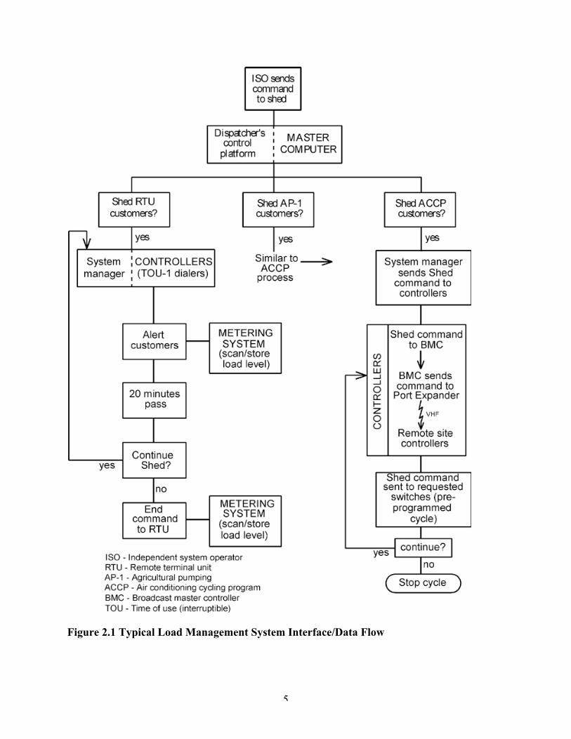
Figure 2-1 illustrates the major functional elements of SCE’s DLC programs, including the loadcontrol receiver (LCR), data communications, the master computer, and the metering system.
Load Control Receiver (LCR) - The critical requirement of the LCR is its ability to respond to acontrol command within a time frame that would allow its impact (i.e., demand reduction) to berealized at the system level soon enough to provide the necessary load shift. Since the time frame“order of magnitude” is specified in minutes (rather that seconds or fractions of seconds), theonly requirement of the LCR is to be able to respond with adequate speed. The LCRs aremicroprocessor controlled and have no internal time delay. Hence, the LCRs themselves caneasily provide this kind of fast load relief load to the electric grid. The ability to get the messageto the receiver on time is an additional requirement that will be discussed next.
Data Communications - For traditional Direct Load Control (DLC) systems, the datacommunications capability of the load control system is the key limiting factor in its ability tosupply reliability or ancillary services. This fact is based on the typical performance of adedicated communication infrastructure - one that is owned and operated by the utility and onethat provides dedicated access.
However, it is important to consider that in many instances around the country, thecommunications system (or more accurately the frequency) must be shared with other utilities.This “sharing” of the communications system inherently makes the communications systemunavailable for critical “time specific” transmission of the control messages. Other systemsaround the country also share the communications medium with paging system providers raisingthe same issues. Even in an ideal situation where an owned and dedicated system exists, thecommunications network combined with the receiver response makes these types of direct load-control systems unacceptable for extremely fast load response applications (e.g., regulation).
The typical response time for a DLC system in a dedicated environment is approximately 10seconds. This means that from the time the system is “commanded” to shed load to the time theload is actually shed is about 10 seconds. The SCADA system must then detect the load shedand feed that information back to the AGC system. It is assumed here that the AGC systemrequires a more instantaneous response in order to maintain ACE.
Another consideration is that the DLC system must control loads (especially diversified loadssuch as Air Conditioners) in such a way that their loads do not loose their natural diversity[critical where duty cycle control (i.e. 15 minutes off and 15 minutes on) is being implemented].This issue implies that the loads are not merely turned off but must be continuously cycled on anappropriate time base (e.g., 30 minutes).

4
Another complexity occurs as the DLC system transitions from apparent load reduction, theeffect of the first load shed command which is basically the average diversified demand of theappliance being controlled, to a more sustainable continuous average load reduction value,integrated over an hour. The sustainable load reduction is considerably less than the apparentload reduction observed early in the load shed process. In summary, as the controlled appliancesare cycled and become “in synch” with control process, the only sustainable load reduction is aresult in the lowering of the natural duty cycle of the appliance. This actual load reduction issignificantly less than the average diversified demand of the appliance.
Master Computer - The Master Computer technical requirements are relatively simple from acontrol perspective. The computer should support a concept known as “Distributed Intelligence”where the LCR determines on its own when to start and stop control thus maintaining appliancediversity. As long as the end control device (i.e., LCR) has this capability, the complexity of thecontrol schemes that must be written into the Master Control Computer can be kept relativelysimple. There are no inherent limitations to the Master Control Computer that inhibit thesystem’s ability to provide ancillary services.
Metering Systems - For a traditional Direct Load Control system, the metering requirements atthe individual customer level do not change. However, if the utility needs to understand what isactually happening at each individual customer (not the case for conventional systems) then themeter would have to be automated so that interval (e.g., 5, 10, 15 minute) consumption datacould be retrieved and analyzed to determine the actual performance of each load controlcommand and event.
5
Figure 2.1 Typical Load Management System Interface/Data Flow

6
3. Requirements for Load Management Resources to Provide Ancillary Services Resourcesto Provide Ancillary Services
This section reviews the requirements for demand-side participation in reliability markets,including conventional and near-term future control and communication needs and hardwarespecifications for each ancillary service. The following ancillary service markets are addressedin the subsections below:• Regulation• Load Following• Voltage Control• Spinning Reserve• Supplemental Reserve• Back-up Supply• Dynamic Scheduling• System Black Start• Time of Use (TOU)
3.1 Ancillary Services Markets
Each subsection below describes technical requirements for the LCR, data communications,master computer, and metering systems for each ancillary service discussed. Detailed technicalspecifications supporting these descriptions are provided in Appendix A.
3.1.1 Regulation
Regulation is the use of on-line generation units equipped with automatic generation control(AGC). These units can change output quickly (MW/minute) to track moment-to-momentfluctuations in customer loads and unintended fluctuations in generation. Regulation helps tomaintain interconnection frequency, minimize differences between actual and scheduled powerflows between control areas, and match generation to load within a control area. This service canbe provided by any appropriately equipped generator that is connected to the grid and is closeenough to the local control area, so that physical and economic transmission limitations do notprevent the import of its power.
3.1.1.1 Load Control Receiver - Overall Technical Requirements
The critical LCR requirement for the regulation ancillary service is the ability to respond to acontrol command swiftly enough so that demand reduction is realized at the system level to shiftload as rapidly as necessary. LCRs are all microprocessor-controlled, so their response timeshould be sufficient to meet the time frame for this ancillary service, which is typically specifiedin minutes (rather than seconds or fractions of seconds). Getting the desired control message tothe receiver in time to implement the desired load reduction is another matter, however. Thisrequirement will be discussed in the next subsections.
For traditional direct load control systems, the data communications capability is the key factorthat limits the system’s ability to supply reliable regulation ancillary services. This analysis is

7
based on the typical performance of a dedicated communications infrastructure – one that isowned and operated by the utility and that provides dedicated access. In many instances aroundthe country, communications frequencies must be shared with other utilities, which means thatthe communications system may be unavailable for critical, time-specific transmission of controlmessages. Some systems around the country share their communications medium with pagingsystem providers, which creates a similar problem. Even in an ideal situation – an owned anddedicated system – network latency combined with receiver response makes these types of directload control systems unacceptable for regulation applications. When a direct load control systemis in a dedicated environment, a command to shed load typically takes on the order of 10 secondsto execute. The system SCADA must then detect the load shedding and feed that informationback to the AGC system. It is assumed that the AGC system requires a more instantaneous typeof response in order to maintain Area Control Error (ACE).
Another consideration is that the direct load control system must manage loads (especiallydiversified loads such as air conditioners) so that natural diversity is not lost (this is criticalwhere duty-cycle control, e.g., 15 off / 15 control, is being implemented). Load must not bemerely turned off but must be continuously controlled (on and off) according to a time base, e.g.,30 minutes. This time frame implies that stopping and starting control is a drawn-out process.Another complexity occurs as the direct load control system transitions from apparent loadreduction – the effect of the first load-shedding command (which is basically the averagediversified demand of the appliance being controlled – to a more sustainable continuous averageload reduction value, integrated over an hour. This sustained value is considerably smaller thanthe apparent load reduction that is observed early in the load shed process. In other words, ascontrolled appliances synchronize with the control process, the only sustainable load reductionresults from the lowering of the overall natural duty cycle of the appliances. This actual loadreduction is significantly less than the average diversified demand of the appliance unless thecontrolled duty cycle is 100 percent.
3.1.1.2 Master Computer Overall Technical Requirements
The master computer technical requirements for the regulation ancillary service are relativelysimple. As long as the end control device (LCR) is relatively “smart,” i.e., it supports distributedintelligence (where the LCR determines, on its own, when to start and stop control, automaticallymaintaining appliance diversity), the control schemes that must be written into the master controlcomputer can be kept relatively simple. There are no inherent limitations in the master controlcomputer that would affect the system’s ability to provide this ancillary service.
3.1.1.3 Metering Systems Overall Technical Requirements
If a traditional direct load control system is used to provide regulation ancillary services, thereare no special metering requirements at the individual customer level. If, however, the utilityneeds to understand what is actually happening at each individual customer site (which is notpossible with conventional systems), meters would have to be “automated” so that interval(five-,10-,15-minute, etc.) consumption data could be retrieved and analyzed to determine actualperformance during each load control event.

8
The types of load control being discussed in this report are focused primarily on the massmarket. Therefore, the most practical method of determining system performance is statistical,which means that individual customer performance is inferred from load research performed on avalid statistical sample of the general population. Overall system performance, in aggregate, canbe recorded at the system level using conventional SCADA monitoring / metering techniques.
3.1.2 Load Following
Load following refers to the use of on-line generation equipment to track changes in customerloads. Load following differs from regulation in three important respects. First, it takes placeover longer time intervals (10 minutes or more rather than minute to minute); so differentgenerators are likely to provide this service. Second, the load-following patterns of individualcustomers are highly correlated with one another, in contrast to regulation patterns, which arelargely uncorrelated. Third, load-following changes are often predictable (e.g., because of theweather dependence of many loads) and have similar day-to-day patterns. Customers can alsoinform the control center of impending changes in their electricity use, and these changes can becaptured with short-term forecasting techniques.
3.1.2.1 Load Control Receiver Overall Technical Requirements
LCRs are controlled by microprocessors and can therefore respond to load control commandsrapidly enough to provide load following within the time intervals that are necessary.
3.1.2.2 Data Communications Overall Technical Requirements
Because load following requires a basic response time on the order of 10 minutes and becausethe load-following patterns of many customers are predictable, this service that could beprovided effectively by a direct load control system. Direct load control systems’ duty-cycledcontrol is an advantage in this scenario because load reduction or increase can be “dispatched” inrelatively small increments by simply adjusting the current duty cycle of the appliances beingcontrolled. Adjustments may be on the order of one minute per half hour, for example. Theresponse time of these changes may still be based on a 30-minute time period, but load responsecan begin almost immediately. Specific control strategies can also be written (although a changein response rate adds complexity to load control strategies and can expose the electricity systemto an undamped load swing scenario if not carefully crafted). In summary, there are no inherentlimitations in the data communications infrastructure that would prevent a direct load controlsystem from providing load following services.
3.1.2.3 Master Computer Overall Technical Requirements
The master control computer must be able to handle the complex control strategies needed toprovide the real-time / on-time responses required by the system dispatcher for load following.The master computer technical requirements should not be an issue if the basic software canrespond to these functional requirements. Because load following is predictable and takes placeover relatively long time frames (10 minutes), the master computer should be able to handle allother requirements.

9
3.1.2.4 Metering Systems Overall Technical Requirements
Load following does not affect metering system requirements unless individual customerresponses must be verified, which would require meter automation that supports data collectionat intervals on the order of one, five, 10 and 15 minutes. These intervals provide sufficientinformation for monitoring individual system performance. This approach is in some wayspreferable using to a direct load control system that monitors itself (a so-called two-way system)because all forms of system failure, e.g., tampering, improper appliance function, poorcommunications, hardware failure, etc. – can be captured. Without metered data, the LCR canonly report its own status and not the status of the entire installation.
3.1.3 Voltage Control
Voltage control entails the injection and / or absorption of reactive power, normally fromgenerators, to regulate transmission voltages. Even though loads themselves cannot logicallysupply these requirements, the load control system could be used to operate reactive powerinjection / absorption equipment.
3.1.3.1 LCR Overall Technical Requirements
The use of conventional LCRs to control reactive power injection / absorption equipment is quitecommon in the U.S. Some utilities have opted for sophisticated monitoring and control (a versionof traditional SCADA) for these applications primarily because they can justify the additionalcost of ensuring that each device goes on line on a real-time basis. The direct load controlsystems described here are “one way,” so the deployment of the reactive power capacity must bemonitored using an existing SCADA system. This monitoring can normally take place at thesubstation if the VAR load on the substation or feeder in question is monitored. The LCRspecified in Section 2.1.1 can perform all of the necessary control functions associated withadding or removing reactive power equipment. The only limiting factor is its inherent inability toconfirm that the intended control function has been carried out.
3.1.3.2 Data Communications Overall Technical Requirements
Most system dispatchers can wait for a dedicated direct load control system’s approximately 10-second response time. A voltage control command would be considered a failure only if aresponse took minutes.
3.1.3.3 Master Computer Overall Technical Requirements
Most direct load control system controllers available today can support the load control strategiesthat will have to be written to provide voltage control.
3.1.3.4 Metering Systems Overall Technical Requirements
The only metering requirements for voltage control are associated with the SCADA system.Individual / end-use meters with voltage and general power quality monitoring capability would

10
greatly enhance the voltage control system’s sophistication and allow dispatchers to increase theaccuracy of their system / distribution voltage adjustments. End-use metering for voltage / powerquality has not generally been considered a requirement for utility voltage regulation activities.SCADA monitoring at substations has generally been considered adequate. See Appendix A fora description of a new product that would could be added to a direct load control system used forvoltage control.
3.1.4 Spinning Reserve
Spinning reserve is generation that responds immediately (within 10 second) to contingenciesand frequency deviations. FERC has defines spinning reserve as the service provided bygenerating units that are on line and loaded at less than maximum output. These units areavailable to serve load immediately in an unexpected contingency, such as an unplanned outageof a generating unit. Spinning reserve must respond immediately to the contingency but only hasto be available for short periods (e.g. 10 minutes) until supplemental reserve comes on line.
3.1.4.1 LCR Overall Technical Requirements
LCRs are controlled by microprocessors, so they should have no difficulty responding within theshort time frames required for spinning reserve services. The only limitation is in the system’sability to sense the need for spinning reserve and then dispatch a command to shed load, whichdictates the performance of direct load control systems in providing this ancillary service.
One way to utilize an LCR for spinning reserve would be to incorporate a system frequencymonitoring capability. (This option is not included in the basic specifications described inAppendix A). The receiver could then be commanded / armed remotely by the system dispatcherto shed load at a particular frequency e.g., 59.7 Hz. If the system decision-making capability is“preloaded” in the LCR, it is not necessary to communicate with the LCR in real time as isrequired for dispatchable spinning reserve functionality. The system dispatcher on a manualbasis, which would eliminate the risk of the system becoming unbalanced, would most likelydetermine Restoration of load.
3.1.4.2 Data Communications Overall Technical Requirements
For spinning reserve, the data communications system would have to support real-time control, acapability that cannot be supported by the conventional direct load control systems specified inAppendix A. To eliminate the real-time control requirement for the data communications system,some additional intelligence must be incorporated in the LCR.
3.1.4.3 Master Computer Overall Technical Requirements
To perform spinning reserve functions, the master computer must be able to respond to an under-frequency condition (sensed by an under-frequency relay), select the required load-sheddingstrategy, and implement the communications and dispatching function, all within 10 seconds.Most direct load control systems in place today could barely support the maximum 10-secondrequirement. In general, the typical spinning reserve function allocated to direct load control

11
systems would be for the first load-shedding event (e.g., at 59.7 Hz). The direct load controlsystem would be shed first with the hope that this load reduction would stabilize the grid beforemore loads would need to be shed by the under-frequency control system that is part of anysystem protection architecture. It is therefore critical that the direct load control system respondin much less that the 10 seconds mentioned above, in order to prevent more critical loads frombeing shed. In general, the application of conventional direct load control systems for theprovision of spinning reserve is not considered practical.
3.1.4.4 Metering Systems Overall Technical Requirements
Metering for spinning reserve would be used primarily for monitoring the performance of thedirect load control system, either at the system level or at the end-user location. Metered end-usedata would allow for accurate compensation of participants where applicable.
3.1.5 Supplemental Reserve
Supplemental reserve is generating capacity that can respond to contingency situations within ashort period of time – usually 10 minutes. Supplemental operation reserve is normally providedby:• generating units that are on line but unloaded• quick-start generation• customer-interrupted load, i.e., load that is curtailed based on a negotiated agreement with a
customer.
Supplemental reserve must be maintained for 20 minutes after it responds to a contingency.
3.1.5.1 LCR Overall Technical Requirements
In comparison to the other ancillary services already discussed, supplemental reserve is theeasiest service for a direct load control system to provide. LCRs are inherently capable ofproviding the necessary control activity within the specified time frame (10 minutes).
3.1.5.2 Data Communications Overall Technical Requirements
The technical requirement for data communications for supplemental reserve is the leaststringent of the requirements for all the ancillary services discussed up to this point. The datacommunications capability of all current direct load control systems, dedicated or shared, caneasily provide the necessary load reduction within the specified 10-minute time frame.
3.1.5.3 Master Computer Overall Technical Requirements
For supplemental reserve, the master computer simply needs to contain the specific controlstrategies that are appropriate. This should not be a problem for most direct load control systems.
3.1.5.4 Metering Systems Overall Technical Requirements

12
As with all of the ancillary services discussed in this report, the ability to monitor eachcustomer’s response to a control request would be helpful in determining fair compensation foreach individual’s actual contribution to meeting system load requirements. Aggregate metering,which is readily available from existing SCADA systems, is more than adequate because overallperformance of the direct load control system can be predicted based on past load researchexperiments and validated after a control event takes place.
3.1.6 Back-up Supply
Back-up supply involves a pre-arrangement that determines how the System Operator willproceed for each load’s loss of primary supply. This supply plan takes effect after spinning andsupplemental reserves have been exhausted (i.e., after 30 minutes). Some loads may find itattractive to provide back-up supply for other loads. The 30-minute lead time allows these loadsto communicate to and curtail their customers to free up power for use as back-up supply.
3.1.6.1 LCR Overall Technical Requirements
Back-up supply can readily be delivered by a conventional direct load control system. Theexpected duration of time during which back-up supply would be needed could be determinedduring contract negotiations to assure that the direct load control system is used only in a waythat is compatible with customer tolerances (e.g., more than five hours’ control of water heaterswould likely be unacceptable to many customers). The LCR requirements for providing back-upsupply are no more demanding than for any of the other ancillary services described in thisreport.
3.1.6.2 Data Communications Overall Technical Requirements
The performance capabilities of a conventional direct load control system can accommodate therequirements for providing back-up supply.
3.1.6.3 Master Computer Overall Technical Requirements
The master computer component of a conventional direct load control system can adequatelyprovide this ancillary service.
3.1.6.4 Metering Systems Overall Technical Requirements
The metering requirements for back-up supply are fundamentally different than for most otherancillary services. Each back-up supply provider is a customer, and it is necessary to documentthat each one meets its contract requirements to shed load. As noted above, a direct load controlsystem can, as part of its design, perform customized load control. However, the conventionalmetering that utilities have in place probably cannot support the delivery of this ancillary service.Individual metering solutions are required that will most likely need to be read in near-real time.If we assume that it would be sufficient for meters to collect data at 15-minute intervals and to beread once per day, several available metering technologies could be used. Because a back-upsupply system will most likely be offered to relatively large commercial and industrial customers

13
who are randomly distributed throughout the service area, a system such as SmartSynch(described in APPENDIX B) would work well. The same meter data could be gathered viaconventional telephone-based meter reading systems available from most of the major metermanufacturers as well as dedicated automated meter reading (AMR) system vendors. The mainmeter manufacturers are ABB, Schlumberger, GE, Siemens, TransData, and Nertec Design.Manufacturers that provide independent, telephone-based meter reading solutions includeTeldata, American Innovations, and Meter Technology Corporation.
3.1.7 Dynamic Scheduling
The Federal Energy Regulatory Commission (FERC) defines dynamic scheduling as electronicmovement of a generation resource or load from the control area in which it is physically locatedto a new control area. Real-time metering, telemetering, and computer software and hardwareare needed to accomplish this load transfer. A load control program in one utility serviceterritory would need to be paired with a comparable load control program in another utilityservice territory in order to provide this service. This possibility is not considered in this reportbecause it requires assumptions we cannot make regarding the “partnering” utilities’ loadmanagement programs.
3.1.8 System Black Start
"Black Start" refers to electric service that can be provided on short notice without supplementalelectric power. Black-start units provide start-up service only in the event of a system-wideshutdown (blackout). Only generation units can provide these start-up services. Hence, a directload control system is not applicable to the provision of this service.
3.2 Current Time-of-Use (TOU) and Real-Time Pricing (RTP) Markets
The subsections below describe TOU and RTP and the overall technical requirements for a directload control system to provide these services.
3.2.1 Time of Use (TOU)
Time-of-Use (TOU) tariffs are pricing plans that apply to specific times of day. These tariffs arenormally fixed – i.e., formally filed with the Public Service Commission and therefore notsubject to dynamic fluctuations based on the actual cost of delivering electricity. TOU tariffs aredetermined by analyzing long-term trends in production costs. Because of the predictability ofTOU rates, a dispatchable load control program can easily be set up to automatically minimizecustomers’ use of energy during periods when TOU rates are high.
3.2.1.1 LCR Overall Technical Requirements
Dispatching a direct load control system for a TOU application is exactly as for mostconventional direct control except that TOU control is performed in response to the requests ofcustomers who wish to avoid high peak-time rates. In other words, direct load control can enablegeneral customer participation in TOU markets. Mass-market energy customers, especially

14
residential consumers, do not currently have a convenient option for managing their energyconsumption. In effect, the utility could implement a load curtailment for a pre-selected enduse(s) on behalf of the customer in response to a high TOU price.
Because TOU tariffs are predictable, the LCR could be designed to accept a specificdownloadable control strategy for each customer. The LCR would have to be equipped with areal-time clock (which must be synchronized with the system master station) to ensure properlocal dispatch of previously downloaded control messages – possibly at midnight the nightbefore they apply. The main benefit of this level of local intelligence is a reduction in datacommunications requirements. In general, the LCR specified in Section 2.1.1 can perform anddeliver this ancillary service.
3.2.1.2 Data Communications Overall Technical Requirements
The functional data communications requirements for TOU tariffs are very similar to those forthe other ancillary services discussed above. However, depending on the specificity of thecontrol functions that the utility offers to consumers, the data throughput requirements couldoverwhelm the communications system. Most direct load control systems today would have tooffer, “pre- packaged” control scenarios that would fit most customers’ TOU needs. Eachcustomer would then pick the control scenario that best suited its individual requirements.
If a dedicated wide area network (WAN) (i.e., the internet) could provide high-speed dataconnections to end-use customers, customer-specific control strategies could be offered. Thiscapability is part of conventional direct load control systems.
3.2.1.3 Master Computer Overall Technical Requirements
Master computer technical requirements could be significantly affected by the increased burdenof supporting additional control strategies for TOU services. The basic function would remainexactly like that for a traditional direct load control system. In general, as long as the componentsof the direct load control system (the data communications system, LCRs, and the associatedmaster computer) function as a package, TOU rates will impose no serious constraint on aconventional master computer system.
3.2.1.4 Metering Systems Overall Technical Requirements
A special TOU meter may be able to provide the interval data needed to verify direct loadcontrol system performance. Customer benefits of responding to TOU price signals should bereflected in energy bills.
An AMR system is often considered an attractive option for TOU rates because the cost of asophisticated TOU meter is about the same as that of AMR with a standard revenue meter. WithAMR systems, energy consumption is accumulated and reported back to a master station via themost appropriate communications system. The details of implementing an AMR system arebeyond the scope of this study, but numerous effective solutions are readily available. These

15
systems use multiple communication infrastructures and display numerous adaptive features forenergy monitoring, each of which adds value to the initial investment.
With AMR, most of the analysis of customer demand and / or energy consumption is performedat the master station rather than within the TOU meter. The benefit of using AMR rather than adedicated TOU meter would be the availability of metered data on demand, which would allowcustom billing and other similar services. Customers could also have access to their individualdata to date on at least a daily basis by means of the internet.
The minimum technical requirement for AMR would be inclusion of device within or attached tothe revenue meter to convert the electromechanical meter’s mechanical energy consumptionaccumulation process into a type of electrical pulse output that could be correlated to energyconsumption. Energy consumption could be calculated from the pulses, and the pulse countcould be relayed through the AMR system for evaluation, validation, and editing if necessary. Asdescribed in Section 4, several attractive AMR systems are currently available.
3.2.2 Real-Time Pricing (RTP)
Real-Time Pricing (RTP) correlates the time of day, week, or month when energy is used toactual production costs at those times. The definition of “time” in RTP varies according to theactual tariff in place – i.e., prices may be posted a day ahead, an hour ahead, etc. As long as thetime frame of the notice is within the operating characteristics of the load control system, thesystem could be used to respond to these price signals.
3.2.2.1 LCR Overall Technical Requirements
Dispatching a direct load control system for an RTP application is exactly the same as for mostconventional applications and for the TOU ancillary service discussed above. RTP is similar toTOU rates (and different from the other ancillary services discussed in this report) because theservice is performed in response to customer requests to participate in the rate plan. In view ofthe time frames most often associated with RTP, e.g., an hour ahead, the LCR must be capable ofreceiving a load-shedding command and implementing it during the hour of interest. An examplemight be that a customer has selects a strategy that allows the heating of domestic hot waterwhen the price is below $0.08/kwh. In this case the LCR would use a permissive scheme ratherthan the interruption scheme that it would normally use.
3.2.2.2 Data Communications Overall Technical RequirementsAs for TOU rates, data communications requirements for RTP are quite similar to those forconventional direct load control.
3.2.2.3 Master Computer Overall Technical Requirements
The master communications technical requirements for RTP are quite similar to those forconventional direct load control.

16
3.2.2.4 Metering Systems Overall Technical Requirements
Of all of the components of load control, the metering system is the element most impacted byRTP. The CellNet system for TOU rates may also be satisfactory for RTP rate structures. Themain issue still being debated in the industry is whether data must be time stamped at the meterrather within the network itself (the CellNet technique). The specific concern is whether billingproblems might arise from occasional data errors or data that are out of synch in real time.Solutions that offer on-site time-stamped data cost significantly more than those that stamp dataon a network. Innovatec Corporation and ATL Metering Ltd. currently offer a mass-market fulltwo-way solution.
3.3 Summary of Ancillary Services Technical Requirements
Table 3.1 summarizes the technical requirements described for the ancillary services in thepreceding sections.

17
Table 3.1 Summary of Ancillary Services Technical RequirementsAS MARKETS
TECHNICALREQUIREMENTS
Regulation Load Following Spinning Reserve
FrequencyResponse
SupplementalReserve
Back-up Supply Current Time-of-Use
TariffsMarkets
Air-Conditioning
Programs
Water PumpsPrograms
DemandRelief
Markets
OtherPotentialMarkets
RemoteCommunicationDevice
• Response: 1-5 Minutes• Real-Time Protocols and
Security• Satellite Interface• PSC Meeting• Other
Response:10-30 Minutes
Response:0.5-10 Minutes
Response:10-30 Minutes
Response:30-60 Minutes
Response:30-60Minutes
Response:30-60 Minutes
DataCommunicationSystem
• Redundant with 99.9%Availability• ICCP• Control Data Protocol
Redundant with99.9%Availability ICCPProtocol
Redundant with99.9%AvailabilityICCP Protocol
Redundant with99.7%AvailabilityProtocol ????
Redundant with99.7%AvailabilityProtocol ???
Redundantwith 99.7%AvailabilityProtocol
Redundantwith 99.7%AvailabilityProtocol
Master ControlComputer System
• Redundant with 99.9%Availability• Real-Time Performance forData Acquisition and ControlAlgorithms• User Friendly• Real-Time Support• Real-Time Database• Other
Redundant with99.9%Availability
Redundant with99.9% Availability
Redundant with99.7%Availability
Redundant with99.7%Availability
? ?
Metering System • Events Data-Start RecordingHardware• SSID Meeting• Other ?????
Yes Yes
Billing System • Events Data-Start RecordingSoftware and Applications• SSID Meting• Other
Yes Yes
Supplier ControlError CalculationInfrastructure
• Yes Yes Yes Yes Yes No No
Type of Aggregation • Probability for 98% percentavailability 100% of the time
Probability for100% percentavailability, 100%of the time
Probability for 100%percent availability,100% of the time

18
4. Identification, Assessment, and Availability of Advanced Load Control Technologies
We divide the load-control technologies discussed in this section into two categories: those basedon a wired communications medium and those based on a wireless medium. These twocategories are further broken down into telephone-based, distribution-line, and broadbandcommunications solutions. Key features, functions, and characteristics are outlined for 12specific technologies.
Section 3 focused exclusively on the one-way, radio-based load-control technology that currentlydominates the national market. In this section, we address more sophisticated, globaltechnologies and systems. Most of these systems are not designed to deliver direct load-controlservices although some can be configured to do so. We describe these systems to demonstratethat numerous solutions already exist that can address the TOU and RTP needs of the electricitymarket. As noted earlier, some of these systems are sufficiently sophisticated that, in addition toproviding price signals, they can also take action in response to load conditions.
4.1 Load Control Technologies that Utilize Wired Communications Infrastructure
The load control technologies that use a wired communications infrastructure described beloware telephone-based solutions, distribution line communications, and broadbandcommunications. For each types of system, the key features, functions supported, and benefits tothe utility are described as well as products offered by specific companies.
4.1.1 Telephone-Based Solutions
The public, switched telephone network (PSTN) is the foundation for all voice and datacommunications and will likely remain so for many years to come. Copper wires generally createlocal loops that connect end users directly to the telephone company central office. Local loopshave evolved to include fiber-optic cable interfaces at intermediate points where the system hasbeen expanded to accommodate increased voice and data traffic. The “switched” portion of thecommunications system is at central offices where system capabilities are adjusted on an as-needed basis. Long-distance connections are routed through a hierarchy of central offices, high-speed trunk lines that connect these offices, and large tandem offices that interface with the InterExchange Carrier (IXC), which handles the long-distance traffic between Local Access andTransport Areas (LATAs). Competitive Access Providers (CAPs) provide networks that bypasslocal telephone company circuits. Voice and data traffic on CAP circuits go directly to the IXC.
Utility communications systems that use the data circuits of the PSTN data circuits mustaccommodate the design criteria of a network designed primarily for voice traffic:• PSTN voice channels provide a bandwidth between 300 and 3,300 Hz. All data traffic must
travel within this bandwidth. Data throughput is limited by the available bandwidth, not bythe physics of copper wire.
• With the application of very sophisticated modulation techniques, data rates of up to 56 kbpsare common today, but the laws of physics limit the possibility of increasing these rates.

19
Figure 4.1 System Diagram of the PSTN
4.1.1.1 ABB / ICS (Integrated Communication Systems)
ABB / ICS’s product is known as the TRANSTEXT Advanced Energy Management (AEM)system. The system monitors energy using a PSTN communications link with the end-usecustomer.
A CEBus-compliant LAN establishes the connection to a customer’s thermostat, water heater,pool pump if applicable, and electric meter. The communications “gateway” also supports awireless link to the outside world so that unscheduled downstream information can bedownloaded to the customer site. Although the AEM system is available, ABB is not activelymarketing it at this time.
The system supports the following functions:• remote meter reading• load control (HVAC, water heater, pool pump, etc.)• TOU Rates
Public Switched TelephoneNetwork
Subscriber
PhoneComputerFax
Central OfficeLocal SwitchCopper Local Loop
OtherCustomers
NetworkInterface
Local Exchange Tandem Access Inter Exchange
Carrier Trunk
LATA (Local Access & Transport Area)

20
The major system components are:• Transtext System Manager (software operating system)
-Used at the utility to send and receive electricity price, usage, and billing information
• Transtext Thermostat-Provides customer interface for price, usage, cost and billing data, and programming
capability for HVAC system, water heater, pool pumps, etc.
• Transtext Controller-Operates HVAC, water heater, pool pump, and thermostat
• Major Appliance Relay-Controls power to water heater and pool pump
• Com Set 4000-Communications Gateway and interface between wide-area network (WAN -- PSTN and
wireless broadcast) and the LAN (CEBus power-line carrier)
• Electric Meter-ABB Alpha-based meter for electricity usage data
The benefits to the utility of this system include:• Improved load management because system permits up to four pricing levels for TOU / RTP
load control.• Better product pricing because system allows flexible rate design.• Improved system load shapes because customers have clear incentive to shift electricity
usage patterns.• Increased operating efficiencies because of improved load factors.• Deferred system capacity additions because of reduced system peak demand.• Increased customer satisfaction because of improved convenience, choice, control, and value.• Improved marketing research/programs.• Improved system forecasting.• Improved ability to monitor program performance.• Improved ability to identify new business opportunities, strengthen competitive position,
retain customer market share, and increase market share.
4.1.12 eLutions
eLutions is an international energy information solutions company created by a joint venturebetween two industry leaders, Invensys Building Systems (IBS) and Engage Networks. eLutionsoffers web-based energy management software, internet-enabled data acquisition hardware, andinstallation services. eLutions services include real-time energy monitoring. Using the internet,customers can monitor energy at the moment it is consumed, anywhere in the world. This abilityallows customers to analyze and negotiate rates and manage load curtailment, aggregation, andusage, among other things. eLutions Support and Energy Partnership (SEP) Bureau offerscomprehensive facility audits, deregulated and regulated rate tariff negotiations, comparative rate

21
analysis, co-generation monitoring and management, curtailment management, real-time pricingtariff management, and many other value-added services.
One eLutions product is Interlane Systems. The residential version is Interlane Home Manager,and the commercial and industrial versions are labeled PM6000 and PM4000. These systemscurrently use the PSTN / Commercial Paging for wide-area access and CEBus and X10 for theLAN. The customer interface is accomplished using a local PC.
The heart of the Interlane system is the Interactive Control Unit (ICU), a 386 industrial computerlocated at the customer’s meter, which creates an interface between the WAN (PSTN) and theLAN (CEBus / X10 power-line carrier) communications network. As mentioned previously, theICU also supports the X-10 two-way power-line carrier protocol.
Measuring modules are attached to individual circuits and transmit power quality information viapower-line carrier to the ICU. A power-line modem (installed on the customer’s PC) andInterlane software are used to communicate with the ICU.
This system supports the following functions:• AMR.• Remote services disconnect/reconnect.• Power-quality monitoring.• Tamper detection.• Load management.• Real-time pricing.• Internet access.• Interactive video - via optional WAN interfaces.• Two-way paging.
The benefits to the utility of this system include:• Reduces operating costs and improves electricity system management, control, and
monitoring by:- load shaping based on variable pricing- emergency load shedding- AMR- remote connect and disconnect- power quality monitoring- remote tamper detect• Builds customer loyalty by providing:- value-added energy information- ability to manage consumption- access to usage patterns and cost

22
• Creates potential for new revenue through:- collaboration with other service providers- flexibility to deploy new customer services- cost-effective addition of interactive services
4.1.1.3 MainStreet Networks
MainStreet Networks is an Internet Gateway Service Provider (IGSP) that partners with utilitiesto put entire homes and their devices on the internet. Utilities purchase and deploy MainStreetNetworks services, based on the MainStreet Internet Gateway, and offer these co-branded e-services to customers. They manage the gateways, operate the network, and providecomprehensive marketing and support. MainStreet Networks open-architecture MainStreetinternet gateway system transforms the customer’s electricity meter into an internet connectionthat can deliver and manage load control services. The MainStreet Internet Gateway platformintegrates the public broadband network (telephone, cable, or wireless) with the homenarrowband network (telephone wiring, power-line carrier, or radio frequency link). MainStreetNetworks system components include:
• MainStreet Internet Gateway - A communications-neutral network computer residing at theutility meter and providing processing, communications, and control resources to supportapplications, store information, and control and protect devices.
• In-home displays – A family of always-on, flat-panel displays with touch-screen navigation.
• Network Operations Center - A secure, redundant centralized network and databasemanagement system that enables utilities to deliver e-services to customers.
This system supports the following functions:
Residential Utility Services is monitoring and meter data collection service enabled by installinga MainStreet Internet Gateway at a residence. This service is remotely managed and operatedfrom MainStreet’s Network Operations Center (NOC). Through the NOC, MainStreet providespartnering utilities with electricity, gas, and water consumption data in a format compatible witheach utility’s billing system.
This system offers utilities the following operational benefits:• Lower meter reading costs• Flexible/aggregated billing• Fewer estimated reads and rereads• Improved operational efficiency• Quicker response to power outages and reduced restoration time and costs
This system offers utilities the following strategic benefits:• Positions partnering utilities to remain sustainable in emerging deregulated electricity
industry• Enhances customer satisfaction and loyalty

23
• Permits turnkey outsource service delivery• Requires no investment in back-office computer equipment• Requires no software or hardware licensing fees• Does not require hiring of technology experts• Offers guaranteed services and performance
Residential Utility Services offers a base level of service and multiple options to meet specificoperational requirements of partnering utilities.
Residential Utility Basic Service includes:• Monthly electricity consumption readings• Tamper notification
Residential Utility Advanced Service includes• Power outage/restoration notification• Ancillary meter reads (gas, water, propane)• Load profile (15, 30, and 60 minute)• Time of use• Physical remote connect/disconnect• On-demand reads
4.1.1.4 Teldata Solutions
Teldata Solutions is a wholly owned subsidiary of myutility, formally owned by National GridGroup. The Teldata system offers a Meter Interface Unit (MIU) that can read all types of revenuemeters – electricity, gas and water. Interface is accomplished via either a dial-inbound or dial-outbound “plain old telephone service” connection. The dial-inbound versions are powered fromthe telephone network. The dial-outbound units utilize the standard Subscriber Line AccessController, located at the telephone company central office and connected to the utility’s CIS.All dial- inbound systems have off- hook detection capability.
This system is primarily intended for AMR and is not intended to provide a true gateway into thecustomer’s premises. Several system trials are under way using a file server connected to theinternet for customer access. The data available include all typical use information as well asgraphics. These systems are only sold to utilities, but the AMR data are available to commercialand industrial end users, aggregators, power marketers, etc.
The link between the MIU and on-site meters is either hardwired or RF. In 1998 TeldataSolutions acquired First Point Services, one of the first companies to offer web-based energyinformation access capability.
Teldata Solutions’ product includes the following components and features:
• Teldata Tds-4 (four port) & Tds-2 (two port) is a multi port data-logger and dial-inboundunit with static and dynamic off-hook detection. The device operates on a customer’s phone linewith no inconvenience to the customer. The device can also be polled on demand with a multi-
24
ring or tone alert. The device reads and stores at user-selected intervals (up to 31 days of 15-min.-interval readings) and calls in at user-selected times. The units requires nominal AC poweror battery (10-year life). Teldata's Multi-Host feature enables the device to be shared bycompeting utilities while securing each utilities data to separate host computers (one per port).
The device is compatible with most pulse-output and three-wire encoded meters. Other featuresinclude peak demand calculation, power outage and restoration reporting, tamper detection, pulseor tone dialing, battery back-up, and a call retry algorithm.
• Teldata Retrofit Optical Scanner is an optically based single-phase electricity meterpulser. The device mounts under the rotating disk of most popular residential and smallcommercial single-phase meters including GE I-70, ABB AB-1, Landis & Gyr MS, andSchlumberger J4S and J5S.
• Teldata ShortHop RF technology enables communication with meters not located near atelephone line. ShortHop works with all meter types and can deliver data to multiple channels foreach data recorder.
• Web-based Energy Information ServicesTeldata Solutions is a pioneer in making meter data usage information available to customersthrough a secure website. Teldata web-based services are secure and may be branded to theutility. This web-based service gives the utility’s commercial and industrial customers rapid,secure access to their usage data and provides customers and the utility with customizablereports.
Teldata Solutions’ units have been primarily deployed in Asia. A single unit costs $50, or $150with whole-house disconnect / telephone communications. The disconnect meter (under theglass, 200A) is relatively inexpensive at $150 (these units typically cost about $250).Teldata Solutions’ product would be especially effective if the company adds a wireless interface(see Innovatec, Section 4.2.1.2) that works with several technologies, i.e. Internet TelemetryCorporation, etc.
Standard features: of the Teldata Solutions’ MIU include:• Built-in modem that communicates to and from the meter for remote data access and
configuration• Data access arrangement for direct AMR• Rolling and block demand calculations for active and reactive power• Four TOU tariff periods with custom weeks, day schedules, and exception days• 16 recording channels with up to 210 days of recording. Up to 1,050 days when using threechannels• One- to 60-minute load profiles• Individual phase currents (calculated)• Multi-symbol LCD with 75mm x 35mm active display area• 200-amp rating, ANSI socket mounting• Infrared optical LED pulse output for accuracy verification• Back-up battery saves all data and settings during power outages

25
• Diagnostic information for tracking meter operation• Data transmission accuracy ensured using CRC-16• Dual level encryption provides data security• Multiple password levels for users and administrator provide management security• Automatic recording of power surges, sags, and outages• Alarms for meter operating variances• Additional Optional Features: Cellular, Cellular Digital Packet Data (CDPD), and paging
communications options
This telephone-based solution can also support some wireless WANs. The price of this product isvery competitive compared to the prices of alternative solutions.
4.1.2 Distribution Line Communications
Figure 4.2 Power-line Carrier System Diagram
Power-line carrier systems transmit very low-frequency signals over utility transmission ordistribution lines. Most applications are for slow-speed data and protective relaying. The typicalfrequency is between five and 100 kHz. Utilities have tried for decades to deploy these systemssuccessfully. One-way applications have proven the most effective; two-way applications havebeen be a major challenge. Two-way PLC systems are available commercially.
A variant of traditional PLC technology utilizes the 60-Hz frequency. Equipment located at theutility computer center controls the system operation, which is based on a unique method ofinbound and outbound signal modulation . Because the system utilizes a 60-Hz signal, data relayis very slow. One major advantage of the 60-Hz frequency is that no major network (distributionline) modifications should be necessary to accommodate this technology.
CustomerPremises
Power Line Carrier
Power CompanySubstation
Meter Electric DistributionNetwork
Utility MasterStation Headend
Leased Line

26
4.1.2.1 Distribution Control Systems, Inc. (DCSI)
The Two-Way Automatic Communication System (TWACS) is a power-line communicationsystem invented and patented in the late 1970s for use primarily by electric and combinationutilities for AMR, load management, and other related functions.
The communication technology utilized by the DCSI System-10 is the patented TWACStechnique of frequency modulation for two-way communication on the power line. Outboundmessages – from substation to the end user – are transmitted by modulating the voltage waveshape near the zero crossover point; binary ones and zeros are indicated simply by the location ofthe modulation. Inbound signaling – from the end user back to the substation – is achieved byapplying a unique pattern of current pulses in the field devices; those pulses are detected in thesubstation. Both techniques produce very small changes to the existing wave shapes,imperceptible to any equipment except DCSI's highly sensitive receiving devices.
TWACS is a fully integrated system that could implement load management, load surveying,AMR, and automated distribution.This system supports the following functions:
Integrated Metering Transponder family:• On-request meter reads (meter data retrieved in 20 seconds or faster).• Tamper, diagnostic, and outage detection and reporting.• Non-volatile electronic memory -- no batteries to fail or wear out.• Built-in 15-minute peak-demand measurement with remote reset.• Individual, unique serial number addressing mode.• Group addressing modes for high system throughput.• System-level time synchronization for profiling, TOU metering, and real-time pricing.• Direct, two-way access to the meter for "hard" service disconnect, demand reset, and
download of parameters and schedules.• Complete under-the-glass solution for single-phase watt-hour meters (Landis & Gyr MS and
MX, ABB D4, D5 and AB-1, Schlumberger J4 and J5, General Electric I70, and GE CanadaI70, Schlumberger’s planned K2 ).
• Water and gas AMR capability using a wide range of interface devices.• Approved for billing by Measurement Canada, Legal Metrology Branch.• TOU Metering.• Load Management.• Distribution Automation.
The benefits to the utility of this system are limited to the applications implemented. At thistime, TWACS is primarily a targeted (AMR, load management) application system. The currentarchitecture does not support creation of a conventional LAN (i.e. CEBus, LonWorks, etc.).Recent discussions with DCSI have indicated a willingness to partner with utilities to develop agateway / LAN based system to implement functions that are not implemented directly with theTWACS communications system.

27
4.1.2.2 Cannon Technologies / EMETCON
EMETCON is a modular automated communications system that utilizes conventional power-line carrier techniques. A relatively high frequency (8-15 kHz) is injected into the electricitysystem distribution network at the distribution substation. Because of the frequency employed,bypass filters must be deployed to keep the signals from being shunted to ground at capacitorbanks.
The main system components are a master station controller located at the utility office, a carriercontrol unit/primary coupling assembly located at the substation to act as the interface with thedistribution network, the electricity distribution network, and the meter and transponderequipment located on the customer’s premises.
EMETCON’S Distribution Line Carrier is a mature communications technology that has beenused by nearly 200 utilities, some for up to 15 years. The system uses a proprietary packet-basedprotocol, which supports the use of store and forward repeaters and has allowed it to become themost widely used form of direct load control with concise, fast, and secure communication. Asimple one-way broadcast load-control command takes approximately one second to transmit. Atwo-way communication takes about four seconds to complete from the master station (usingdedicated phone line). If a repeater is included in the routing, the time is a few seconds longer.Data packets are small and typically carry only a few data points at a time. The end-point devicescannot initiate a communication without being polled by the Carrier Control Unit (CCU), so allcommunication is very tightly controlled and routed. The computer handles routing and retriesfor failed communications.
A major benefit of this type of distribution line carrier approach is its utilization of a singlechannel for both two-way and one-way broadcast communications. The resulting "network" is online full time for quick access. No license is required for installation, and the system is utilityowned.
Figure 4.2 shows the basic components of a distribution line carrier injection point. This pole-mounted setup includes a single high-voltage coupling; however, a single CCU can support up toeight couplings at different voltages. A sub with two buses, one at 13.8 kV and one at 24.9 kV, isan example.
Starting from the bottom, a dedicated phone circuit connects the CCU to the master stationcomputer at the utility office. This connection could use any form of two-way communication,including radio, dedicated fiber, etc. The CCU is housed in a weatherproof cabinet and can bemounted outdoors or indoors. It contains card slots much like those of a personal computer.Component cards are inserted into these slots and can be swapped for troubleshooting.
The CCU transmits a digital signal in the form of a sine wave at 9.6 or 12.5 kHz. This frequencyis induced onto the copper distribution line through the Signal Coupling Unit (SCU), a smallgray box fastened to the capacitor rack. The coupling capacitors act as a "high-voltage gateway"for this signal, with very high voltage on the high-side bushing and low voltages on the groundside. The grounding conductor of the capacitor bank is passed through the SCU, and the data

28
packet signal is induced onto this ground through an isolation transformer in the SCU. TheEMETCON signal then propagates down the line omni-directionally.
Receivers and transponders located out on the distribution feeder "hear" this data packet andrespond. Repeaters like the one shown in Figure 4.2 will digitally repeat the data packets whenthey are part of the routing. The CCU also includes a receiver card that hears the responsescoming back from the polled devices or repeaters.
This system supports the following functions:• Automated Distribution• AMR• Load Management• TOU Metering• On-demand reads• Remote Connect/Disconnect• Load Surveys
4.1.3 Broadband Communications Solutions
A hybrid fiber-optic and coaxial (HFC) network results when most of a cable TV network hasbeen upgraded to fiber-optic cable but a last network node remains in coaxial cable, usuallyserving 250 to 500 homes. By upgrading its one-way amplifiers to two-way, the cable systemcan provide a return link to the head end. The typical bandwidth available in these HFC networksis 750 MHz; some go as high as 1 GHz. The frequency range for upstream (return path to thehead end) transmissions is usually allocated to the five to 42 MHz portion of the availablespectrum, and downstream transmissions occupy the balance of the available bandwidth. Theportion of the base band between 54 and 450 MHz is generally left alone so that the system cancontinue broadcasting the existing analog TV channels. Per IEEE 802.14, the upstream spectrumwill be broken into channels from a few hundred kHz to approximately 1 MHz, and thedownstream spectrum into six-MHz channels in the 54-MHz to 450-MHz portion of thebaseband and one-MHz in the 450- to 750-MHz portion. Utilization of modulation techniquessuch as Quadrature Phase Shift Keying (QPSK) allows data rates of approximately two to threeMbps to be supported on the upstream channels. The downstream channels utilize 64-quadratureamplitude modulation (QAM) and can deliver data rates of approximately 30 Mbps. To takeadvantage of this data capability, the end-use customer must employ the appropriate cablemodem. The IEEE 802.14 working group is finishing the development of the appropriateindustry standards for these modems.
The most significant characteristic that separates an HFC network from its CATV forerunners isthe ability to provide full-duplex (simultaneous two-way) high-bandwidth connections to the enduser. These systems have evolved from a simple CATV system to a full-blown, broadband, bi-directional communications system. An HFC network is “always on” because of the packet-switched nature of the connection with the ISP. As soon as the user turns on his/her PC, the ISPsets up a new internet connection.

29
Figure 4.3 System Diagram for an HFC Network
4.1.3.2 Comverge Technologies, Inc.• MAINGATE Utility Automation System
Comverge Technologies, Inc. purchased the Scientific Atlanta (SA) Control Systems Division in1999. The old SA Control Systems Division (which eventually merged with the SA BroadbandGroup) was a premier supplier of load management systems for electric utilities. The merger ofthat division with the Broadband Group resulted in the development of a utility-focusedapplication of HFC broadband infrastructures. The product is the MAINGATE UtilityAutomation System. It uses an existing cable TV HFC system for the WAN link back to theutility master station equipment. The MAINGATE system includes a “gateway” at the home,which provides the interface between the WAN and the LAN on the customer premises. TheLAN may be CEBus, LonWorks, etc. The full duplex data rate to the end user will be 128 Kbpsutilizing one MHz of HFC system bandwidth. Comverge intends to support multiple WANinterfaces, including satellite, cellular, and hybrid systems. A new project has been announcedthat uses broadcast radio (VHF paging) for outbound initialization, and the PSTN for remoteinbound communications.
The system supports the following functions:• AMR• Customer-Controlled Load Management• Real-Time Pricing• Home Automation and Servicing• Customer Messaging• Remote Connect/Disconnect• Outage Verification• Tamper Detection
Analog CableVideo Headend
Distribution SubscribersPSTN Office PremisesInterface Optical Optical Coax
Fiber NodeDigital 250-500 Homes
SubscribersVideo Premises
Hybrid Fiber Coax

30
The primary benefits to the utility of this system are cost and system scaleability/flexibility. Asmentioned previously, a true LAN/WAN system infrastructure in this price range is unique in theindustry. The ability to scale up to additional applications over time creates a very “futureproof” system.
Comverge Technologies Inc. in 1998 licensed the technical information, software, andequipment from the Lucent Technologies Customer Connection for Utilities and an associatedpending patent. Lucent Technologies, formally part of American Telephone and Telegraph(AT&T), consists of Bell Labs, and Network Systems, Microelectronics, Multimedia ProductsGroup and Business Communication Systems. The Comverge solution for electric utilitycustomer communications, originally known as the Lucent Customer Connection, is now knownas Comverge Customer Connection. The initial commercial product provided a WAN/LANinterface utilizing an HFC WAN and a CEBus LAN on the customer premises (secondary of theelectric system distribution transformer). The Comverge solution in intended to provide aplatform for full-service customer solutions for electric utilities.
Figure 4.4 Comverge Customer Connection System Diagram
The Comverge Distributed Connection is a Cellular Digital Packet Data (CDPD) meter-readingsystem. Comverge Technologies provides a cost-effective means of using the high-quality,widely deployed CDPD network to read interval data from commercial and industrial (C&I)customers. Its initial cost is low, it is easy to install, and it has the lowest operating cost of anycommunications system. The system provides rapid deployment for geographically dispersedcustomers.
The turnkey Comverge system includes meter interfaces for electronic or pulse output metersand the comprehensive, scalable software to control and operate the system. In addition, the

31
customer can access data via an internet web page. Comverge also provides options for usingCEBus (EIA-600) power-line interfaces to hub multiple meters within a location or to controldevices on the power line. This CEBus option enables cost-effective demand control, reportingof real-time energy prices, interval metering for load profiling, and other value-added services.
The system supports the following functions:• Immediate AMR• Outage Detection• Service Connect/Disconnect• Real-Time Load Management• Distribution Automation• Tamper Detection• Power-Quality Monitoring• Security• RTP• Customer-Controlled Load Management• Appliance Monitoring
4.1.3.3 muNet
muNet's internet metering and communication gateway technology enables utilities and servicecompanies to use residential and commercial customer data to enhance service to thesecustomers. From an open standard gateway device located at the electricity meter, muNet offerssecure two-way communication with customer sites for electric, gas, water, and broadbandutilities as well as providers of other home services, such as energy management and appliancemaintenance. muNet's innovative product line leverages three trends - internet availability, utilityrestructuring, and home networking. In addition to their potential for use by multiple utilities andservice providers, muNet's open architecture systems offer significant cost and performanceadvantages over existing systems requiring proprietary networks.
Since 1997, muNet has been developing WebGate™, an internet solution that connectselectricity meters directly to the Utility’s Customer Information System. WebGate integrates thecustomer meter and the utility’s CIS using AMR, enabling Remote Device Control and providingcustomers access to both historical and instantaneous data directly from their meters. Direct two-way communication with customers through the meter also creates the opportunity for the utilityto provide programs and services such as TOU and RTP, demand load management, and energymanagement services. muNet's connection between the customer, the meter, and the utility isestablished using the internet, which avoids the problems associated with traditional AMRsystems. WebGate™ offers full two-way AMR communication without the need to deploy aproprietary network or expensive head-end control hardware.
To make WebGate™ a broad-based solution that will accommodate the changing utility marketplace, muNet has committed its R&D to a standards-based open architecture development path,which will give systems the flexibility to grow and expand in response to future needs.

32
Figure 4.5 muNet’s Webgate System Diagram
The current system supports broadband interface options such as CATV / HFC, DSL, andEthernet. The meter output is standard Ethernet, which interfaces with a cable or DSL modem. Astandard telephone interface is not currently available. The meter becomes its own website forinternet access through any standard browser.
The WebGate™ iRIS can provide information to utilities and customers as soon as the site unitis installed and an internet connection is established. The unit can acquire pulse output frommeters other than electricity (gas, water) on site using two external channels. The site unit canalso access and control other devices/systems on site. Examples of applications of thisconnectivity are: whole- house disconnect or load restriction, remote load shedding by means ofthermostat control, and remote appliance diagnostics. The WebGate™ iRIS gateway usesstandards-based open-architecture protocols, including XML. The in-house LAN is based on awireless (902 to 928 MHz) protocol using a Microsoft-supported standard for open systems. Thehard-disconnect option (200 amp) is implemented with a hard-wired interface between the meterand the disconnect relay. Retrofit is an option (under the glass) for legacy electromechanicalmeters.
4.2 Load Control Technologies that Primarily Utilize Wireless CommunicationsInfrastructure
The subsections below describe load control technologies that rely on wireless communications:unlicensed spread spectrum applications and private fixed cellular networks. The functionssupported and benefits of these systems are listed, and products offered by specific companiesare described.
4.2.1 Unlicensed Spread Spectrum
Most applications of unlicensed spread spectrum are for wireless LANs. However, onemanufacturer (Metricom) has implemented a regional network using this technology. The systemoperates in the 902-928 MHz unlicensed area of the radio spectrum and uses intelligent radios to

33
create a multipoint-to-multipoint wireless data network intended for electric, water, oil, and gasutility applications. The system operates at a 100-Kbps raw channel throughput [compared to19.2 Kbps for commercial packet radio systems (ARDIS)] with up to 28.8 Kbps actualthroughput. Higher throughput might be possible in the future. This system uses Code DivisionMultiple Access to spread the signals over the allocated spectrum.
Two key issues associated with this type of system are:• Unlicensed spectrum users are by definition burdened when there is co-channel interference.• The system shares the spectrum with numerous consumer electronic devices.
Figure 4.6 Unlicensed spread Spectrum System Diagram
4.2.1.1 Internet Telemetry Corporation (iTC)
Internet Telemetry Corporation is an information-gathering and processing service that transmitsdata through two-way proprietary wireless equipment known as the IMR Server, which isinstalled at a customer's premises. Originally a startup business unit of WilliamsCommunications Group Inc., Internet Telemetry Service was founded in 1997 and is currentlyconducting system trials with national companies.
In iTC’s system, Telemetry Interface Modules, mounted on meters and other devices to bemonitored, gather and transmit data to a local IMR Server. The IMR Server forwards the data tothe National Operating Center -- via a national WAN that includes wireless (SkyTel) and long-haul fiber systems interconnected by Williams' own asynchronous transfer mode (ATM)network. Data are recorded every 15 minutes and transmitted daily or whenever a significantevent occurs on the network. Information gathered at the National Operating Center (in TulsaOK) is processed, stored in databases, and routed to clients. Computer services also includeenergy usage analysis, billing packages, internet inquiry services, and a wide range of energymanagement services. In addition, the WinGate units can be used for numerous information-based applications, such as message delivery and monitoring.
Mobile Customer
Radio RepeaterRelay Station Repeater Radio
Relay StationWired Access Point
PSTNT/R
T/R
T/R
T/R
Unlicensed Spread Spectrum
CustomerPremises
UtilityMaster Station

34
This system supports the following functions:• Monitoring of electric, gas, and water meters to efficiently manage deregulated energy sales.• Monitoring and control of thermostats to support energy management systems.• Monitoring and control of HVAC and lighting to reduce energy consumption.• Monitoring of alarm sensors as back-up for telephone reporting .• Distribution of electronic coupons into the home.• Distribution of voice, computer, and multimedia data.
Typical system users are power utilities, energy providers/energy service companies, andnational retail chains.
Figure 4.7 System Diagram
4.2.1.2 Innovatec Corporation
Innovatec’s system is a true, 100-percent two-way system that does not require a secondary fixedcellular infrastructure like other systems described previously. This system uses an existingWAN that can be provided by numerous common carriers for the back-haul function.
Appliance ProxyServerPush IP ClientWinGateWireless Internet GatewayInternet Service CenterUtility MetersGas.ApplTM,Water.ApplTM andElectric.ApplTMSub-MetersGas.ApplT

35
Innovatec uses 900-MHz direct sequence spread spectrum to create a two-way LAN network thatcollects meter information and can support additional value-added services such as security, loadmanagement, environmental monitoring, etc. From a communications perspective, this systemappears capable of implementing most if not all “narrowband” value-added customer servicescurrently being considered by utilities.
The system gateway communicates with the 900-MHz transceivers and retransmits informationto the utility using existing common-carrier networks. The amount of information that can bestored at the gateway or meter site is currently unknown. The gateway is normally polemounted.
When multiple utilities (water, gas, etc.) use the system, the electricity meter can function as arepeater, which allows for a reduced power output and therefore a smaller drain on the batteriesfor each unit.
The Innovatec system is a very powerful composite solution. The most obvious concern is thecost per point, which is significantly higher than can be justified by most utilities for mass-market meter reading in today’s world. Not only is the meter costly, but a utility must replace itsexisting meter inventory to use this system. This requirement would be a huge obstacle for mostutilities.
System deployment valued at approximately $20 M is pending for SCANA corporation.Innovatec is targeting municipal markets because of the company’s innovative water (pit set)solution for wet environments with a flat-surface-mount antenna for the pit lid. In time,Innovatec may be forced to develop a less expensive one-way solution for the mass market.There seems to be some consensus in the industry that the residential mass market will notdemand the kind of rigorous data that can be delivered through full-blown two-way meteringsolutions.
Having a gateway for the first level of data retrieval is typical. If the gateway uses SkyTel as itsWAN interface, it would closely replicate the iTC SkyTel (at least in the field).
The system architecture suggests that the system head end (NOC) would be maintained at theutility corporate office and that data are not routed over the internet through any kind of separateNOC. As a result, the system would not offer value-added web posting of data, etc.
4.2.1.3 Nexus Data
Nexus Data’s system is currently primarily a one-way RF solution using direct-sequence spreadspectrum with data collectors mounted on communication towers to reduce infrastructure cost. Itis an under-the-glass solution for the ABB electromechanical 1ø and Schlumberger 1ø Centronmeters. The ABB solution includes the optical pulse initiator, which is an integral part of thatcircuit board. The Nexus Data transmitter reports actual register readings for the ABB orCentron as well as tamper detection (reverse meter rotation). A local handheld device is used tosynchronize the meter register reading and transmitter at the time of installation for the ABB.

36
For the Centron, the Nexus system actually drives the meter register and therefore cannot beuncoordinated.
Typical cell size ranges from five to 10 miles. For a 3,000-square-mile service area, an estimated70 to 80 receiver sites would be required. Each receiver/cell can support 86,400 time slots ormeter readings per day. Each time slot is one minute, and each receiver supports two carrierfrequencies. (Each carrier supports 43,200 one-minute time slots). The actual transmission timeis 150 ms, so the probability of collisions is relatively low. The system also employs the “captureeffect” to avoid collision problems, using three receivers to cover a particular area; eachtransmitter can be received by each receiver station. The system uses one-watt transmitters toincrease range of meter transmitters (for electricity, water, and gas). The gas and watertransmitters use lithium batteries that are supposed to last 10 years. The receiver base stationantennas are typically 150 to 300 feet high. Time stamping takes place at the receiver server.
Two-way units for are being developed C&I customers to support synchronized time-stampeddata for demand billing, service disconnect/reconnect, and TOU billing. The two-way systemwill not utilize the 900-MHz ISM band for downstream transmission. That link could be paging,either private or public. The most likely data retrieval method will be via the data port in themeter (RS 232) where the data are already stored. The company is prepared to provide the downlink time synch needed by the meter and to perform the “billing read” function, which resets theregister demand values. Neither solution is contemplated for “high end” C&I customers. It iscurrently anticipated that a dedicated link to those customers’ sites would use technology suchas the Siemens / SmartSynch / SkyTel solution. The company is not currently using its systemfor these customers because of the number of data that would be routed through the network.
The NOC for this system can be owned by the utility or outsourced to Nexus Data. Jointownership options are also available. The NOC collects all of the data and routes them to theutility systems.
4.2.2 Private Fixed Cellular
The implementation of privately owned fixed cellular networks is very attractive to electricutilities interested in system automation that does not require the types of exotic applications thatcan be provided by more robust telecommunications options (HFC, FTTC, etc.). Privately ownedfixed cellular networks are offered primarily by ITRON (Genesis), Whisper, and CellNet DataSystems. CellNet uses the privately authorized 900-MHz Multiple Address Systems ( MAS )frequency band for the back-haul portion of the system. ITRON has replaced its 900-MHzsystem with a 1.4-GHz network, which provides high-speed network for DistributionAutomation as well as links to customers for basic energy management services. Whisper usesthe 900-MHz unlicensed spectrum for the home link and the fist several hops of back haul. Therest of the back-haul network is provided by other telecommunications infrastructure. The lastlink in all of these networks – to the end user – operates in the unlicensed portion of the 900-MHz spectrum (902-928 MHz) and utilizes its own range of spread-spectrum techniques. Thissystem is not currently designed for true gateway access to the home for interactive services,home automation, etc. because of limited data capacity. However, within the scope of traditionalutility applications, the network provides more than adequate throughput capacity.

37
Figure 4.8 Private fixed Cellular Network System Diagram
4.2.2.1 Itron, Inc.
The Itron solution is an open architecture system designed to incorporate de facto industrystandards to allow interoperable design. The system also provides transparent gateways to othercommunication infrastructures and applications. It supports incremental automation strategiesthat optimize technology investments and allows for the integration of existing utilitycommunications and data processing infrastructures. The Genesis family of products provides amultimedia, multi-applications system solution for AMR, Distribution Automation, and demand-side management (DSM).
The Genesis system is built primarily around its licensed fixed cellular infrastructure combinedwith an unlicensed radio link to the meter. It can also interface with power-line carriers,telephone, and gateways to other industry standard networks. In addition, utilizing either hand-held or vehicle-mounted interrogation units supports off-site, mobile AMR.
The primary components of the fixed network are the meter module (ERT), the first dataconcentrator (Cell Control Unit), the second major network element (Network Control Node),and the Host Processor. The communications system for the back haul of the meter data utilizesan Itron nationwide-licensed frequency in the 1.4-GHz band. All ERTs operate in the unlicensed902-928 MHz band.
System Master Utility MainframeHost Processor Legacy Systems
Network Network NetworkControl Control ControlNode Node Node
Cell Control Node Cell Control Node Cell Control Node Distribution Automation Network Node
Residential ResidentialInterface Interface
leased line
Private Fixed Cellular Networks

38
A “Micro Network” is available that allows for precise network deployment. It currentlysupports the ERT family of products that report consumption. The capability to add demandreporting is currently being developed. A C&I network utilizing the Itron licensed 1.4-GHzfrequencies has also been developed to replace a telephone line for C&I customers connected tothe MV-90 host.
Figure 4.9 Elements of the Itron System
The Itron system supports the following functions:
• AMR (one-way & one-and-a-half-way)• TOU• Load Profile• Virtual Service Connect / Disconnect• Tamper Detection• Outage Detection• Leak Detection• Scheduled / Unscheduled Meter Reads• Group Load Profile• Group TOU• Consolidated Billing• Demand (Fixed Network)

39
The utility benefits associated with Itron system deployment are tactical and strategic. Thetactical benefits are direct reduction in the cost of traditional utility functions (AMR, etc.) andimproved system efficiency (Distribution Automation). The strategic benefits may have moreimpact in the long run by preparing the utility for the developing competitive environment.However, the system by itself does not support a “gateway” interface to the home and as a resultcannot offer the more sophisticated energy/customer services associated with that kind ofcapability.
4.2.2.2 CellNet Systems (Purchased by Schlumberger 5/2000)
CellNet systems offer a wireless direct data link between the utility and its customers. Thesesystems utilize a typical fixed cellular structure consisting of small cells that link back to anetwork accumulator and finally to a host processor.
The microcell LAN provides the link to the electric meter [microcell controller – (MCC)]. Thisportion of the system operates in the unlicensed spectrum and incorporates spread spectrumtechnology. The cell is anchored by a Cell Master, which communicates with the MCC onlicensed frequencies. It also connects back to the Master System Controller, which manages theentire system. The meter module is a transmit-only device that operates in the unlicensed portionof the spectrum and incorporates direct-sequence spread spectrum technology. The meter modulemounts under the glass of the existing electric meter.
CellNet’s marketing strategy is not based on the sale of the system hardware and software butinstead on establishing long-term (20+-year) outsourcing contracts for applications that arepurchased by individual utilities. CellNet will also market additional services (monitoring ofvending machines, copiers, etc.) to non-utility companies.
The CellNet system supports the following functions:• AMR (one-way)• Distribution Automation• TOU Metering• RTP• Real-Time Load Profiling• Remote Service Connect / Disconnect• Gateway to MV - 90• Gateway to SCADA• Outage Detection
The utility benefits from the CellNet system are primarily reduced system operating costs.Additional non-traditional services could also be purchased to implement strategic customerservices. These services could also be targeted to generate additional cash flow for the utility.

40
Figure 4.10 CellNet System Diagram
CellNet's wireless LAN (to the meter, etc.) communications use a direct-sequence spreadspectrum radio technology ideal for economically and reliably communicating short bursts ofdata to and from millions of end points. Low-power links ensure minimal transmissioninterference, and built-in Cyclical Redundant Checking (CRC) error-checking protocols andhardware redundancy provide the highest data reliability.

41
5. Summary Prioritization and Comparison of Technologies
Table 5.1 compares the technologies / systems described in this report and their applicability toancillary services. These technologies are identified as the ones that could permit near-term,widespread penetration of load management services as a system reliability resource in theancillary services markets described in Section 3.

42
Table 5.1 Summary Comparison: Applicability of Technologies to Ancillary Services Markets
Technology Regulation LoadFollowing
VoltageControl
SpinningReserve
SupplementReserves
Back-upSupply
DynamicScheduling
SystemBlackStart
TOU Real-Time
Pricing1-Way Direct Load Marginal Good Good Only If
ModifiedGood Good N/A N/A Good
(Note2)Good
(Note2)Schlumberger/CellNet N/A N/A Good Only If
ModifiedN/A N/A Good N/A Good Good
Itron/Genesis N/A N/A N/A N/A N/A N/A Good N/A Good Good
ABB/Transtext N/A Good N/A N/A Good Good Good N/A Good Good
elutions (Interlane) N/A Good N/A N/A Good Good Good N/A Good Good
Main Street Networks N/A Good N/A N/A Good Good Good N/A Good Good
Teldata Solutions N/A N/A N/A N/A N/A N/A Good N/A Good Good
Meter Technology N/A N/A N/A N/A N/A N/A Good N/A Good Good
DCSI/TWACS N/A Good Good Only IfModified
Good Good Good N/A Good(Note2)
Good(Note2)
Cannon/Emetcom N/A Good Good Only IfModified
Good Good Good N/A Good(Note2)
Good(Note2)
Comverge Good Good N/A Only IfModified
Good Good Good N/A Good(Note2)
Good(Note2)
muNet Good Good N/A Only IfModified
Good Good Good N/A Good(Note2)
Good(Note2)
Internet TelemetryCorp
N/A Good Good Only IfModified
Good Good Good N/A Good Good
Nexus Data N/A N/A N/A N/A N/A N/A Good N/A Good Good

43
APPENDIX A
This appendix details the specifications of the key elements of a modified load managementinfrastructure that would be required for SCE’s current direct load control infrastructure toprovide the system reliability resources described in this report:
• load control receiver (LCR)• data communications• master computer• metering system
A.1 Load Control Receivers
This subsection describes the technical and functional criteria for the Load Control Receivers(LCRs) that would be part of SCE’s radio-based Direct Load Control system. These receivers arenormally associated with the implementation of a mass market/ residential load management butcan easily be adapted to commercial and industrial applications.
The system utilizes radio frequencies for communication, so system components must meetFederal Communications Commission (FCC) interference requirements. Any modifications tothis system must be compatible with communications systems already in place, includingcommercial TV and radio as well as standard commercial, industrial, and public safety mobileradio systems.
A.1.1 Detailed Technical Specifications for LCRs
The subsections below list detailed technical specifications for LCRs.
A.1.1.1 General Requirements
General requirements for LCRs are:
• Operating Temperature -30 to +60° C• Input Voltage capability and stability 24 VAC: +25% to -10% 120 / 208 / 240 VAC: +10% to
-10%NOTE: one LCR would be used for low-voltage applications and another for high-voltageapplications
A.1.1.2 Energy Consumption
LCR energy consumption should meet the following criteria:
• 24 VAC: 2.0 VA max. All internal and external relays de-energized.• 12.0 VA max. All internal and external relays energized• 120/208/240 VAC: Typical energy consumption for the non-energized state is 2.0 VA; when
two internal and four external relays are energized, typical consumption is 8.0 VA.

44
A.1.1.3 Transient Voltage Protection
• LCRs should meet the latest American National Standards Institute (ANSI) specifications(current version is C37-91.1-1980). All products should have field test procedures that canbe used to verify the functioning of the internal transient protection system. This testingpermits operators to distinguish between microprocessor malfunctions and major problemsthat might require the product to be sent out for repair.
A.1.1.4 Physical Environment
LCRs should be able to withstand the effects of any anticipated external influences and weatherconditions, including common-mode noise and low-level as well as high-frequency, fast-rise-time, low-energy transients. Most LCRs include “watchdog” timers that may be utilized toaccomplish this task.
A.1.1.5 Factory Quality Assurance Testing
Utilities should verify that manufacturers test and “burn in” all units as they are built; thiseliminates the need for on-site testing prior to installation.
A.1.1.6 Momentary Relay Contact Bounce
It is critical to end uses controlled by the system that LCR control relays do not momentarilychange state (open and close) during a subtle LCR status change; this is especially importantduring power outages / restorations.
A.1.1.7 Thermostat “Droop” Compensation
LCRS should be designed so that an “open” / under control status of one of the low-voltagerelays (to be designated R1) will cause a current of 8 milliamps (±1mA) @ 24VAC to flowthrough the “open” contacts into a resistive 3,000-ohm load. The circuit design voltage shouldbe rated for 120 VAC. An onboard jumper, pin, or etc. should be provided that can be removedor cut to disable this current flow.
A.1.1.8 Radio Receiver Section
Operating frequency of the radio receiver station should be appropriate for the paging / dedicatedsystem transmitter frequency, with the following additional characteristics:• Spurious and Image Rejection - 40 decibels (dB) from carrier reference, measured when the
receiver is matched to a 50-ohm impedance• Capture Ratio - 6 dB maximum• Selectivity - 50 dB @ ±20 kHz• Frequency Stability - ± 0.002%, -30° C to +60° C• Radio Frequency (RF) Sensitivity- With the receiver mounted in its normal vertical
orientation, the maximum electrical field strength required for 100-percent operationalsuccess is 10 µV/m @ 2.0KHz frequency deviation when operating in the AFSK mode.

45
A.1.1.9 Control Relays and Remote Relay Driver
General Specifications for control relays and remote relay driver are a life expectancy of 100,000operations at rated load and a voltage rating of 2 kV @ 60Hz.
The internal relays should meet the following specifications:• Low Power: Two Form-C Contacts (R1 & R3) should be provided with a rating of five amps
@ 120 VAC (resistive load) and 40 VA @ 24 VAC (inductive)
• High Power: One Form-B relay (R2) should be provided with a minimum rating of 30 amps@ 240 VAC (resistive load) and 1 HP @ 120 VAC (inductive).
The external relays should meet the following specifications:• Low Power: Three Form-C Contacts, 5 amps @ 120VAC (resistive load) and 40 VA@
24VAC (inductive), 24-Volt AC coil voltage, with integral wiring harness compatible withmanufacturer’s standard wiring color code. All conductors should be # 18 AWG and at leasteight inches in length. This relay interfaces with the internal R1 relay to meet the occasionalneed for more than one control contact operating in conjunction with R1.
• High Power: One Form-C relay, 30 amps @ 240VAC (resistive load) and 1 HP @ 120 VAC(inductive), in a weatherproof enclosure with integral wiring harness compatible with theremote driver circuit specified in the next section. The high-voltage leads should be at least #12 AWG, the low-voltage # 18 AWG; all leads should be at least eight inches in length.
• Remote Relay Driver Circuit (R2A) - The LCR should be capable of remotely controlling anexternally mounted relay from its internal power supply. When energized for controlactivity, this circuit should be rated for continuous duty operation and should always operatein complete synchronization with the internal high-power relay (R2).
A.1.1.10 Functional Specifications
• Digital Message Protocol / Decoder Requirements
LCRs should utilize a robust communications protocol that is readily available from themanufacturer’s standard product offerings. Typically approved load management messageprotocols are:• Cannon Technologies, Inc. - STANDARD VERSACOM and EXTENDED VERSACOM• Regency Technologies - STANDARD VERSACOM and VCOM (if available)• Comverge Technologies, Inc. - SA 205 / 206 / 305
One desirable protocol feature relates to synchronization of low- and high-power relays. Thelow-power relays (R1 & R3) should always start control at the same time (assuming that a“shed” command for both relays has been received by the load control device). The high-power30-amp relay (R2) and remote control driver circuit (R2A) must always be completelysynchronized. Both sets of relays (low and high power) may be synchronized by random chance;they should not be forced into synchronization. The two low-power internal relays each have

46
selectable time-out characteristics or duration parameters but must begin control insynchronization. The remote relay driver circuit for the remote control of an external relayshould always be in synchronization with the high-power relay (start and stop). Thissynchronization requirement is necessary because the low-power relays may be controlling aportion of the same appliance; their coordination ensures the implementation of fail-safeappliance control logic. The high-power relay and remote driver will not necessarily controlportions of the same appliance, but the appliances they control will likely be similar or related,i.e., pool pump and pool sweep.
• Tamper Detect and Notification
The LCR should be able to detect unauthorized disconnection by sensing occasional current flowthrough the internal relay contacts. An internally set time frame determines how long a “no-current” (presumed disconnect) condition can exist before a “tamper” is registered. The receivershould have a visual indication of this “tamper detect” status. It should not be reset by poweroutages, and a typical time frame would be 90 days. The actual time frame will be downloadedto the receiver through the communications protocol.
• LCR Failure Rates
Manufacturers should specify a maximum guaranteed annual failure rate for LCRs.
• Cold Load Pickup
Cold load pickup is the unilateral action taken by an LCR when power is restored after aninterruption. This action normally involves the implementation of a control or shed action forsome if not all control functions. The effect of this operation is to keep certain customerappliances off for a period of time immediately after power restoration in order to reduce themagnitude of the now-synchronized electrical load on the distribution circuit (i.e., all naturaldiversity of electrical loads is lost after a power outage). The reduced demand on the electricalcircuit will significantly assist the utility’s attempts to restore power.
Receiver persistence is the LCR’s ability to ignore short-term (typically one- to three-minute)power outages. This feature in the cold load pickup application allows the receiver to continue tocarry out the instructions that it last received and to address the unique relationship between coldload pickup and any existing control action as dictated by the system’s implementation strategy.
The cold load pickup status of the receiver (enabled or disabled) should be user programmableand selectable for each individual control relay. The receivers should be shipped from thefactory with cold load pickup enabled so that the installers will not have to address nuisancecontrol.
• Historical Event Counters
LCRs should store various operational parameters, including the number of times each relay anddriver circuit operate; the number of radio signal receipt verification / internal diagnostic test

47
commands passed; the elapsed time since receipt of memory clear; all receiver individual, group,division, substation, feeder, transformer, etc. address information; tamper detect information;and cold load pickup status. This information should be read and reset locally without openingthe receiver compartment by means of a handheld portable test device. It should be possible tofreeze all internal memory counts from the Master Station Controller so that this information canbe retrieved at a later date. Freeze commands should be implemented using the master stationsoftware and system communications protocol.• Internal Diagnostics
LCRs should automatically monitor their own functional status. Results should be indicated onthe LCR the visual display so that an inspector can readily see them. Monitoring should includeverification of internal relay continuity (coil), microprocessor internal function, and transmittedmessage error detection (i.e., CRC implementation.
• Receiver Visual Indicators
LCRs should be designed to include visual status indicators that are viewable without openingthe receiver enclosure. These visual indicators are typically LEDs that display the status ofcontrolled loads as well as the condition of the receiver itself. This function also includes opticaltransmission of data to an external test device.
• Test Equipment
Test equipment that can implement all aspects of the LCR capability should be a part of themanufacturer’s package. This equipment should be used for installation, troubleshooting, andverifying system performance.
• Universal Telecommunications Capability
LCRs should be designed and built to become compatible with the two-way interactivetelecommunications technologies currently becoming available, including Hybrid Fiber / Coax,Satellite, Ethernet Local Area Networks (CEBUS, LONWORKS), etc. This capability shouldbe in the form of a universal interface arrangement so that a plug-in daughter board can beinstalled to provide an interface with the network being deployed. The LCR itself is generic, butthe daughter board is specifically designed for a particular telecommunications interface. Thisoption should allow access to the receiver’s various status parameters stored in memory. Theretrievable information should, at a minimum, equal the data available through the remoteoptical reader device.
• Physical ConfigurationThe enclosure should be a rain-tight enclosure with a hinged door, National ElectricalManufacturers Association (NEMA) 3R, suitable for outdoor installation. Mounting tabs shouldsupport the physical attachment of the receiver to the customer structure. The enclosure shouldalso be approved and listed by the appropriate national standards, particularly UnderwritersLaboratory (UL) 916. Wiring entrances should be clearly described. At least one 3/4" nipple with

48
a bug seal around all exiting wire pigtails should be provided. An alternate approach couldinclude an internal junction box for high- and low-voltage power relay connections.
• External Wire Specifications-Insulation (All conductors) - 600 VAC, 105 °C-Conductor Size
Low-Power Relays and Remote Driver Circuit - #18 AWG StrandHigh-Power Relay - #12 AWG StrandedPower Supply Input - #18 AWG StrandedLength - All conductors eight inches in lengthColor Code - Manufacturer’s Standard Offering
• Internal and External LabelsAll external labels should conform to UL listing requirements and be designed not to fade or become brittle from outdoor conditions for a period of 20 years.
• Labeling informationA front cover label should show the receiver PC board serial number and theutility corporate logo. A receiver wiring interface diagram should appear on the inside of theenclosure back panel. A removable inventory control label should be available to be attachedto an installation work order for tracking purposes.
A.1.2 Industry Standards
All LCRs should conform to the latest version of the following standards or the requirements ofthe following agencies:
National Electric CodeAmerican National Standards InstituteInstitute of Electrical and Electronic Engineers (IEEE)American Society of Mechanical EngineersNational Electrical Manufacturers Association (NEMA)Underwriters Laboratory (UL)Federal Communications Commission (Part 15)
A.2 Data Communications
The load management master station controller typically connects to three separate datanetworks. The first and simplest controls remote transmitters, usually through a standard, four-wire, 600-ohm balanced, phone-line type circuit. The load management vendor typically suppliesall hardware and software necessary to remotely interface with the selected paging / private radiotransmitter system.
A remote transmitter controller (RTC) is typically used for a dedicated / utility-ownedtransmitter system. The physical interface between the RTC and the RF transmitter system isunique and is normally be described in detail in a vendor's response to a Request for Proposal.

49
Using today’s technology, it is assumed that the RF modulation of the transmitter will beFrequency Shift Keying (FSK), commonly referred to as digital transmission. With this type oftransmitter modulation, the remote transmitter controller must generate the appropriate mark /space digital outputs.
The transmitter control for a paging system normally uses the paging system’s standard interfacefor sending pages. The load management system’s control message / protocol is converted to anASCII format and is transmitted as a page to the LCR. A paging-based system worth seriousconsideration offers the flexibility to switch paging carriers after LCRs are installed in the field;business conditions or technical problems could prompt a need to switch paging carriers.
Figure A .1
The second load management master station controller data interface requirement involves theEnergy Management System (EMS) / Supervisory Control and Data Acquisition (SCADA)system. A typical EMS could be running on a redundant IBM 360 with a universal interactiveexecutive (UNIX) operating system. EMSs often utilize an Ethernet Local Area Network (LAN)for local networking. The load management master station controller connects to the LAN via anRS232 serial interface that could be provided by a component of the EMS package. Analternative interface is a direct connection to the Ethernet LAN through an existing unused tap.All data transfer between the EMS and load management master station controller will normallypass through this physical interface.The external interface to the EMS may require a special software package. The utility shouldassist in determining the nature of that software and any other coordination required between anEMS vendor and a load management system contractor. Any modification or enhancement of
Ethernet LAN
LM Master Station
EMS Ethernet
LAN EMS
UHF/VHF Paging / Private RF
Transmitter System
Typical Load Management System Interface / Data Flow
Requires: Dedicated 4 Wire 600 Ohm Balanced Phone Line Type Circuit
F i r e w a l l Firewall
Corporate Customer Information System
Load Management Customer Information Management System

50
the EMS for the implementation of a load management system should be included in the scope ofa direct load control system specification and should be part of the system provider’s costestimate. Likely modifications to existing EMSs should include a program that will implementthe dispatcher interface and allow for passage of system status and control information to andfrom the EMS. It is recommended that the load management system supplier contract directlywith the EMS vendor to implement the vendor’s specific interface requirements.
The load management master station controller interface is for all data transfers between the loadmanagement master station controller and the load management Customer InformationManagement System (CIMS), utility Customer Information System (CIS), trouble management,marketing, and project management personnel. This interface will normally be made directly toan existing company Ethernet LAN.
A.2.1 System Security Architecture Issues
System security is discussed in the subsections below.
A.2.1.1 Securing Physical Interfaces
As indicated in Figure A.1, all physical interfaces among the proposed load management CIMS,the load management master station, the existing corporate internal network, and the EMSnetwork should be protected with appropriate security devices (routers or firewalls) so that onlyauthorized individuals or processes can access these systems. Product vendors should work withthe utility’s network architecture and information technology (IT) security personnel to ensurethe appropriate configuration and integration of these devices with the proposed system.
A.2.1.2 User Authentication to System
User access to the proposed load management system should be restricted using an approved,industry-standard authentication mechanism. An example of an approved mechanism would besigned certificates and a SSL protocol from an internet browser on each end user's workstation.
A.2.1.3 Dial-up Access
Remote dial-up access to the system should be supported by the vendor utilizing a secure dial-upmechanism (Shiva's LanRover Access Switches w/ AceServer SecureID validation would be anexample). Direct modem connections to any of the load management system components(server, workstations, etc.) would not normally be allowed.
A.2.1.4 Applications Systems Interfaces
All interfaces to existing applications from the load management system should be approved bythe corporate IT application support group responsible for maintaining those applications.Any batch data transmissions that may a part of the load management system interface shoulduse secure, encrypted, industry-standard protocols. An example of this would be the secure shell

51
(SSH) protocol. Non-secured, non-encrypted file transfer protocol transmissions betweeninternal systems and external vendor-supported systems would not normally be allowed.
A.2.1.5 Very High-Frequency (VHF) / Ultra High-Frequency (UHF) Radio System Design
The utility typically determines the expected coverage for signal reception for the loadmanagement radio system. The system vendor and paging system vendor provide radio systemcoverage data if the system is implemented using an existing paging infrastructure.Communication is typically considered successful with a 95-percent success rate, 95 percent ofthe time.
A.3 Master Computer
The general specifications for a Master Computer system for a typical radio-based, one-waydirect load control system are summarized in the subsections below.
2.3.1 General Hardware RequirementsThe system vendor will normally provide all equipment necessary for implementation of acomplete Master Station Controller System, including computers, keyboards, monitors, printers,interface ports, modems, and ancillary interface equipment.
The master station controller system platform should be state-of-the-art IBM-compatiblepersonal computers adequate to support the functional requirements described in this report. Itshould be possible to upgrade the system to a fully redundant configuration based on themanufacturer’s standard failure-sensing scheme.
Typical system components are:
• Pentium III IBM PC-compatible computer with keyboard and mouse• 19-inch high-resolution super video graphics array (SVGA) or better color monitor• 128 megabytes (MB )of random access memory (RAM)• 40-gigbyte (GB) hard drive, minimum• compact disc (CD) read/write drive (8x or better)• 3.5 floppy disk drive• printers - report and event• modem for transmitter control• 56-Kbps dial-up modem for remote access• 10/100 Ethernet Network Interface Card
The master station controller should include a real-time clock configured so that time and datewill not require reinitialization after power outages. An interface with an existing SCADA / EMSsystem clock is a desirable strategy for meeting this requirement.
Remote dial-up access to the master station controller may be provided via a 56-Kbps modem.The option to add a second dial-up modem is desirable. System access must conform to allcorporate security requirements.

52
A.3.2 General Software Requirements
The Master Station Controller System should utilize an advanced multi-tasking operating systemcapable of supporting multiple simultaneous programs, a graphical user interface, and queued,prioritized commands. The complete operating software package should be furnished, includingthe source code. The manufacturer could, as an option, establish a trust that could be used toguarantee access to the code. The intent is to prevent problems with software maintenanceand/or enhancements if the vendor goes out of business or terminates its support of the system.
The graphical user interface for the master station controller system should use a Windowsformat that supports a multi-tasking environment. This interface should provide operational anddiagnostic aids, including on-line “help” functions.
If there is a loss of power to the master station controller, the computer must automaticallyrestart and resume control without operator intervention.
The master station controller’s database should be fully relational with structured query language(SQL) compatibility. The database files should utilize a standard database package such as MSAccess, Microsoft SQL Server, Oracle, etc. Proprietary, vendor-specific database file formats arenormally not acceptable.
The master station controller should provide a real-time and historical facility that allows thegraphing of any data points that have been stored in the system. This capability must beextremely user friendly, including a context-sensitive help system, graphical interface, andcursor-driven editing. Standard 24-hour system load curves should be available, including theability to display the time and value of any point in the display.
A.3.3 Functional Requirements
Load management control “strategies” (consisting of multiple control commands) will normallybe initiated by one of the following means: a time-of-day schedule, external data input (such asthe automated ancillary service requirements specified in this document), or in response to aspecific command from the system operator. External operation includes “feedback”mechanisms that automatically initiate load control to manage total system demand or,additionally, transmission, distribution feeder, and substation demand to a desirable limit. Thisapplication requires system load / demand inputs [provided by the EMS / Independent SystemOperator (ISO)] from various metering points strategically placed throughout the serviceterritory. From these data, the system projects the need for load management and respondsaccordingly. A typical dispatcher-initiated control strategy could be derived from a MW loadreduction value that has been input to the system. The load management master station softwarewill initiate the control strategy that corresponds to that level of reduction. The dispatcher mayalso request an increase or decrease in load reduction during the run time of the previousoperation, and the system must automatically adjust to that request.

53
Control strategy prioritization should allow the system administrator to assign the priority orderin which several simultaneous control strategies will be implemented. The system dispatchershould be able to link these “prioritized” strategies to system events.
The system should be able to integrate all automatic control activities while providing thedispatcher with override capability. The system dispatcher must be able to modify automaticcontrol in any way that meets system requirements, i.e., increase or decrease load reduction,cancel control, etc.
The direct control (load off) of specific customer appliances for various extended periods of timeshould be supported. This should include the ability to execute a delay period before operationand to initiate a control activity that will continue for a period of time specified by the operator.The restoration activity should be based either on a time-out characteristic or the implementationof a “distributed intelligence” control. Distributed intelligence is a form of random controlintended to ensure a smooth process. It can simulate natural appliance diversity even after anextended load-shedding event. This type of load management is described in detail in Section2.1.1. The distributed intelligence specification is included in the receiver specifications becausethis capability is, by definition, provided by the software within the load control device ratherthan the master station.
Cyclic control should allow the system operator to implement various duty cycles and cycleperiods for different types of loads, i.e., the time base for load control should be selectable. Anexample would be a time base that would allow loads to be shed regularly for some specifiedamount of time, e.g., 10 minutes out of every 30 minutes. Ten minutes off during a 30-minutetime base is a 33-percent off-time duty cycle. The user should always define these parameters.
The system dispatcher should be able to terminate load control immediately or by using thedistributed intelligence capability described above.
The load management master station controller should support a protocol that delivers anindividually addressable (Direct Load Control Switch) load management control system. Thenumber of available addresses is typically in the millions. The master station should also be ableto implement various hierarchical characteristics inherent in the protocol. A typical hierarchicalstructure is: System Address or Utility I.D.; Utility Division; Substation; Feeder; Transformer,etc. The manufacturer should reserve a sequential series of serial number addresses for all futurepurchases for this system. This range of numbers will typically provide millions of individualaddresses / serial numbers.
The load control receiver address / configuration assignment is coordinated by the loadmanagement master station controller and the Customer Information Management System.Customers should be able to vary their load management participation, which will meanchanging their control specifications. Changes are implemented using the system protocol andlink back to the individual customer address that the protocol provides. Bidders proposing toprovide load management control services should describe in detail their methods of determiningthe customer’s participation variables.

54
Cold load pick-up, the ability to automatically shed customer appliances when power is restoredafter a sustained outage, should be supported so that each receiver control relay can have its owndownloadable cold load pick-up configuration via the load management master station controller.Bidders to provide load management services should describe their standard methodologies forimplementing Cold Load Pickup.
The load management system should account for whether a customer is “in” or “out” of service.When a customer is out of service, the receiver should respond only to a command to return thecustomer to active service; it should not respond to control or cold load pickup commands. Thesystem should support identification of customer status based both on contractual agreementsand temporary changes in status in response to customer requests. Temporary status changesshould be failsafe so that the customer is automatically restored to normal status after apredetermined time period. Customer service status should also be stored in nonvolatilememory.
The load management system should be able to command the LCR to implement an internaldiagnostic test and radio signal receipt verification. The system should be capable ofimplementing this test sequence approximately once per minute during idle system conditions.The test signal will be utilized by installers and troubleshooters to quickly the status identify ofthe LCR.
To support troubleshooting analysis, a history of control activity and other relevant informationfor each receiver should be maintained in the Master Station Controller database as well as theLCR itself. The load control and communications success information stored in the receivermemory should be locally accessible by means of portable test equipment; this equipment andthe Master Station Controller should both be able to reset this information to zero. The ability tofreeze receiver memory counters is also desirable.
A.3.4 Customer Information Management System (CIMS)
A CIMS is a critical separate component of the system because the required functionality cannotor may not be provided using the existing corporate Customer Information System (CIS).
The CIMS should be used for tracking and generating load management customer participationinformation. The system should accommodate real-time inquiries about the control status andcontrol history of individual customers, summary reports, work order forms, and other customerservice activities.
The load management CIMS should reside on its own dedicated platform and located with theLoad Management Master Station Controller. It should interface with the load managementmaster station controller using the existing corporate local area network.Some of the specific items that should be tracked are:• customer name• account number• Address• phone number(s)

55
• switch (LCR) serial number• switch (LCR) address settings and configurations• date of sign up• date work order assigned to contractor• installation date• cold load pick up status• in- and out-of-service history• load management hardware inventory• customer appliance statistics, i.e., (BTU, watts, gallons, condition, etc.)• utility electricity service information:- Division, substation, feeder, transformer, pole, etc.- Customer control history
Multiple switch installations per customer location should be supported. The database shouldaccommodate millions of customer records.
The system should also provide numerous reports relating to customer status, installationspecifics, trouble call history, cycling history, etc. An example would be a report writer such asSeagate Crystal Reports, which is a widely used windows tool.
The existing corporate CIMS should transmit a standard-format (e.g., ASCII) file to the loadmanagement CIMS each night. The load management CIMS should use this downloaded file toadd and delete customers to/from the load management program and address any other customerparticipation criteria. The file transfer should include customer information from the corporateCIS (Name, Address, Phone number, Account number, etc.). On a nightly basis, the loadmanagement CIMS will create a standard format file of control activities that have taken placesince the previous upload. This file will be uploaded from the load management CIMS and usedto create the daily transactions history necessary for the mainframe corporate CIS. Periodically,e.g., on a monthly basis, the entire load management CIMS “customer information” will beupdated from the corporate CIS. This should ensure that the two systems’ customer recordsremain consistent.
Typical system components are a 500-MHz Pentium III IBM PC-compatible computer with:• keyboard and mouse
19-inch high-resolution (SVGA or better) color monitor• 128 Mbytes of RAM• 40-Gbyte hard drive, minimum• CD R/W drive (8x or better)• 3.5 floppy disk drive• printer• 56-Kbps dial - up modem for remote access• 10/100 Ethernet Network Interface Card

56
• ORACLE database structure
Figure A.2. shows a flow chart representation of a load management CIMS.
Figure A.2
Load Management Customer
Information Management System
Customer Information System Mainframe
File Transfer
Daily
Activity
Load Management CIMS
Maintenance
Transactions

57
APPENDIX B
A relatively new product currently being manufactured by SmartSynch Corporation andmarketed through Siemens would be an ideal addition to a direct load control system that is usedto implement voltage control by managing reactive power elements on the distribution system.The SmartSynch system provides not only three-phase power information (interval data, etc.) but
basic power quality information including voltage sags, swells, etc. The actual number ofSmartSynch meters would be limited to the number of reactive power elements under control;therefore, the overall cost impacts of adding this product to a system would be negligible.SmartSynch provides a SkyTel communications package that fits under the glass of poly-phaseelectricity meters (currently Siemens S4, others under development). The communicationpackage delivers consumption and demand data and can also deliver the entire meter database.The SmartSynch system determines customer-specific power quality parameters and reports anydesired alarm condition. The power quality portion of the system is event driven. Thecommunication module, power supply, and antenna are all self-contained under the meter cover,resulting in significantly lower installation costs.
SmartSynch delivers wireless, two-way IP connectivity to energy and utility companies andprovides a cost-efficient AMR capability for C&I customers. Smart meters generate and transmitdata on the quantity of the resource used and the quality of its delivery. Power-quality andreliability reporting functions allow the utility company to inform C&I customers immediately ofoutages, interruptions, or fluctuations. These value-added, fee-paid services offer customerscritical information while providing the utility company an opportunity for additional revenuestreams. The return on investment (ROI) cycle for the utility company can be less than two yearscompared to the ROI for phone modem systems. The customer / utility notification system usesthe SkyTel two-way paging network and email.
The benefits to the utility of this system include:
• Automated network registration and coordination offer “plug and play” metercommissioning. No coordination of modem, meter, communication circuits, and masterstation means low-risk, rapid deployment and reduced project costs.
• M32 Transaction Server (Windows NT)The “head-end” transaction management system, M32, was developed to leverage multipleprocessors and distributed NT computing, and complement other Microsoft applications. It isobject oriented; the M32 system is configured using drag and drop objects, wizards, etc. Ithas built-in SQL and ODBC permitting sharing of information throughout an enterprise, i.e.MV-90 and / or Energy Interactive for instance for web posting, etc. The M32 head end maybe purchased for on-site deployment or an application service provider contract can benegotiated with SmartSynch to provide the M32 on an outsourced basis.
• Spectrum Information Efficiency for the SkyTel System

58
Low data overhead because of innovative data parsing, data compression, and protocolmanagement at both the meter and the host
• IP Data with Forward Error Correction (FEC)Interlocked packet switched IP data with FEC for data security and efficiency.
• Power-Quality / Reliability Reporting FunctionsOutage reporting, sag/swell alarms, volts/amps per phase, voltage imbalance, nominalvoltage, etc. Offers C&I customers a value added (fee paid) service. The ability to calculateand report phase-to-phase voltage problems directly from the meter is unique in the industryas is the ability to select customer-specific parameters for alarm reporting.
• Wireless BenefitsIn contrast to phone modem technology, SmartSynch meters are wireless IP devices that arealways on and always connected to the network and the internet. This continuous connectionwith the SkyTel network via the Narrowband PCS Control Channel provides the time-synchronization process so critical for accurate demand and interval data reporting as well asmaintaining the accuracy of the internal meter clock.
• Two-Way Internet ConnectivityWith event-driven alerts, the SmartSynch system uses paging (wireless messaging toindividuals or groups), automated e-mail, fax, and phone messages with web interface to givethe utility and its customers access to data reports.
• Motorola CreataLink 2XT TransceiverA mass-produced and field proven WAN gateway device with critical mass economies ofscale and high reliability provides the basic RF communications capability. Two-Watt RFoutput and +3 dB gain internal antenna result in outstanding RF field performance andsuperior “in building” penetration.
• No Additional Field Network Infrastructure RequiredNo towers, repeaters, routers, transmitters, receivers, batteries/UPS, no site leases, notelephone company contracts, etc.
• Premium Integrated Data Network - SkyTelBy using an established (hardened) commercial RF communications infrastructure, the utilitycan eliminate licensing, design, construction, operation, maintenance, and risk of a lessrobust private network and can share high infrastructure costs with other commercial users.
• SkyTel simulcast communicationSupports multiple transmitter and receiver network coordination in same end-point area forsuperior in-building penetration.
• SkyTel broadcast capabilitiesFor load curtailment, RTP, device reprogram, messaging, etc. not supportedby PSTN and some wireless networks.

59
• Full two-way customer communicationSupports outage and restoration notice, spontaneous power-quality events, load control, RTP,remote connect/disconnect, pre-pay metering, two-way customer messaging, and other value-added services.
• IP addressable SkyTel wireless network is an extension of the internet that powers allSmartSynch meters field devices as nodes on the internet.
• Nationwide data network with costs that do not change with message distance, i.e., no long-distance toll charges for distant or national C&I accounts.
• Extensive RF coverage network and a cooperative network service provider strategy tocustomize coverage and meet future AMR service requirements.
Simple meter installation procedures and tools such as the portable, lunch-box-sized RFCoverage Validation Unit (CVU). The CVU is a self-contained go/no-go device thatautomatically records site metrics and is designed to be used by workers with minimum skills.
• Handheld Motorola PageWriter 2000 wireless PDA facilitates meter installation and servesas a remote wireless operator interface with the SmartSynch / SkyTel system.
• Efficient Messages - size and structure are optimized for AMR data payloads.
• On September 25, 2000 SmartSynch announced that, in partnership with Siemens PowerTransmission & Distribution, Inc., it has added power quality and reliability monitoring to itsenergy and utility wireless data services portfolio. As mentioned earlier, Siemens markets thesystem to utilities throughout the U.S.