ERDC/CRREL TR-14-9 'Vehicle impact testing of snow roads ... · The snow roads at McMurdo Station...
65
ERDC/CRREL TR-14-9 Engineering for Polar Operations, Logistics, and Research (EPOLAR) Vehicle Impact Testing of Snow Roads at McMurdo Station, Antarctica Cold Regions Research and Engineering Laboratory Sally A. Shoop, Margaret A. Knuth, Wendy L. Wieder, and Monica Preston June 2014 Approved for public release; distribution is unlimited.
Transcript of ERDC/CRREL TR-14-9 'Vehicle impact testing of snow roads ... · The snow roads at McMurdo Station...

ERD
C/CR
REL
TR-1
4-9
Engineering for Polar Operations, Logistics, and Research (EPOLAR)
Vehicle Impact Testing of Snow Roads at McMurdo Station, Antarctica
Cold
Reg
ions
Res
earc
h an
d En
gine
erin
g La
bora
tory
Sally A. Shoop, Margaret A. Knuth, Wendy L. Wieder, and Monica Preston
June 2014
Approved for public release; distribution is unlimited.

The U.S. Army Engineer Research and Development Center (ERDC) solves the nation’s toughest engineering and environmental challenges. ERDC develops innovative solutions in civil and military engineering, geospatial sciences, water resources, and environmental sciences for the Army, the Department of Defense, civilian agencies, and our nation’s public good. Find out more at www.erdc.usace.army.mil.
To search for other technical reports published by ERDC, visit the ERDC online library at http://acwc.sdp.sirsi.net/client/default.

Engineering for Polar Operations, Logistics, and Research (EPOLAR)
ERDC/CRREL TR-14-9 June 2014
Vehicle Impact Testing of Snow Roads at McMurdo Station, Antarctica
Sally A. Shoop, Margaret A. Knuth, and Monica Preston Cold Regions Research and Engineering Laboratory (CRREL) U.S. Army Engineer Research and Development Center 72 Lyme Road Hanover, NH 03755-1290
Wendy L. Wieder Science and Technology Corporation 21 Enterprise Parkway, Suite 150 Hampton, VA 23666-6413
Final Report
Approved for public release; distribution is unlimited.
Prepared for National Science Foundation, Division of Polar Programs 4201 Wilson Boulevard Arlington, VA 22230
Under Engineering for Polar Operations, Logistics, and Research (EPOLAR) EP-ANT-12-03, “Snow Roads and Transportation”

ERDC/CRREL TR-14-9 iv
Abstract
In December 2009, a study was conducted to determine how vehicle oper-ations impact snow roads. The snow roads at McMurdo Station are the primary transport corridors to move personnel and material from the air-fields servicing intra- and inter-continental flights. Thus, they are a critical transportation component and are also particularly susceptible to deterio-ration during warm temperatures. This study explored methodology to quantify the impact of various vehicles, tires, driving speeds, and maneu-vers on snow-road conditions. The specific impacts of turning, accelera-tion, braking, and speed were isolated using spirals, circles, and straight-line testing on compacted snow surfaces. Portions of the active snow-road system were also used in a road course involving corners and surface roughness. Measurements included the strength of the snow surface in and between tire tracks, tire-track rut depth and width, and the height and width of the resulting snow piles adjacent to the tire tracks. The experi-ments yielded valuable guidance regarding what types of testing and measurements could most easily differentiate performance. Results indi-cate the impacts of driving speed and vehicle type, including the im-portance of the tire and suspension components, on preserving satisfacto-ry snow-road surfaces through the melt season.
DISCLAIMER: The contents of this report are not to be used for advertising, publication, or promotional purposes. Citation of trade names does not constitute an official endorsement or approval of the use of such commercial products. All product names and trademarks cited are the property of their respective owners. The findings of this report are not to be construed as an official Department of the Army position unless so designated by other authorized documents. DESTROY THIS REPORT WHEN NO LONGER NEEDED. DO NOT RETURN IT TO THE ORIGINATOR.

ERDC/CRREL TR-14-9 v
Contents Abstract .......................................................................................................................................................... iv
Illustrations ...................................................................................................................................................vii
Preface ........................................................................................................................................................... ix
Acronyms, Abbreviations, and Symbols ....................................................................................................x
Unit Conversion Factors ............................................................................................................................. xi
1 Introduction ............................................................................................................................................ 1 1.1 Issue ................................................................................................................................ 1 1.2 Background and approach ............................................................................................. 2
2 Equipment .............................................................................................................................................. 5 2.1 Snow strength measurements ....................................................................................... 5 2.1.1 Rammsonde Snow Penetrometer ............................................................................................. 5 2.1.2 Clegg Impact Hammer ............................................................................................................... 6
2.2 Impact measurements ................................................................................................... 7 2.3 Test vehicles .................................................................................................................... 8
3 Test Sites .............................................................................................................................................. 11 3.1 Locations ....................................................................................................................... 11 3.1.1 Long Duration Balloon Pad ..................................................................................................... 11 3.1.2 Road course ............................................................................................................................. 12
3.2 Initial site characterization ........................................................................................... 12
4 Spiral and Circle Tests........................................................................................................................ 16 4.1 Testing ........................................................................................................................... 16 4.1.1 F350 truck spiral and circle tests (A1, A1, and A4) ............................................................... 17 4.1.2 E350 van spiral tests (B1 and B2) ......................................................................................... 19 4.1.3 Terra Bus and Delta circle tests (C1 and C5) ......................................................................... 22
4.2 Analysis ......................................................................................................................... 23 4.2.1 Effect of the turning radius on vehicle impact ....................................................................... 23 4.2.2 Comparison between vehicles ................................................................................................ 25 4.2.3 Comparison of TRXUS and Cepek tires .................................................................................. 26
5 Straight Line Tests (acceleration, constant speed, and deceleration) .................................... 27 5.1 Testing ........................................................................................................................... 27 5.2 Comparison of tires ...................................................................................................... 29
6 Road Course Tests .............................................................................................................................. 31 6.1 Terra Bus ....................................................................................................................... 32 6.2 Delta .............................................................................................................................. 35

ERDC/CRREL TR-14-9 vi
6.3 Analysis ......................................................................................................................... 37
7 Summary and Conclusions ............................................................................................................... 38
References ................................................................................................................................................... 40
Appendix A: Additional Clegg Data ......................................................................................................... 41
Appendix B: Snow-Road Driver’s Training .............................................................................................. 43
Report Documentation Page

ERDC/CRREL TR-14-9 vii
Illustrations
Figures
1 Map of McMurdo Station road and airfield system for the 2009–2010 season (with north up) ................................................................................................................................. 1
2 Rammsonde snow hardness profiling measurement ............................................................... 6 3 Clegg Impact Hammer measuring road surface strength ........................................................ 7 4 Rut depth was measured from the original snow surface to the deepest part of
the rut ............................................................................................................................................... 8 5 The height of the pile on the side of the rut was measured from the undisturbed
snow surface ................................................................................................................................... 8 6 Ford F350 fleet operations truck ................................................................................................. 9 7 Ford E350 Van .............................................................................................................................. 10 8 Foremost Terra Bus ...................................................................................................................... 10 9 Foremost Delta ............................................................................................................................. 10 10 Satellite image of the LDB Pad (red circle) and road test course (yellow) with
north downward (29 October 2009 WorldView Satellite at 0.5m resolution) ...................... 11 11 Clegg and Rammsonde strength-measurement test points for the LDB Pad and
for the road course ....................................................................................................................... 12 12 Medium Clegg data for the LDB Pad initial site characterization .......................................... 13 13 LDB Pad strength profile ............................................................................................................. 14 14 Road course strength profile from the Rammsonde. Data taken in the Delta lane
are in blue; Terra Bus lane data is red. The measurement locations are shown in Figure 11........................................................................................................................................ 15
15 Counterclockwise spiral test configuration ............................................................................... 16 16 Clegg surface strength measurements for counterclockwise (left turn) spiral test
A1 with the fleet operations truck (old Denman tires) ............................................................ 17 17 Rut and pile measurements for counterclockwise spiral test A1 with the Fleet
Operations F350 Truck (old Denman tires) .............................................................................. 18 18 Clegg snow surface strength measurements for counterclockwise spiral test B1
with Van 206 (old Cepek tires) ................................................................................................... 19 19 Rut and pile measurements for counterclockwise spiral test B1 with Van 206
(old Cepek tires) ............................................................................................................................ 20 20 Clegg snow surface strength measurements for counterclockwise spiral test B2
with Van 213 (new Interco TRXUS M/T tires) ........................................................................... 21 21 Rut and pile measurements for counterclockwise spiral test B2 with Van 213
(new Interco TRXUS M/T tires) .................................................................................................... 21 22 Average medium Clegg reading of surface strength measurements for clockwise
circle tests with the Terra Bus (C1) and the Delta (C5) ........................................................... 22 23 Rut measurement from spiral maneuver A1 using the fleet operations truck
(older Denman tires) .................................................................................................................... 23

ERDC/CRREL TR-14-9 viii
24 Impact of fleet operations truck ................................................................................................. 24 25 Circle test rut depths for the fleet operations truck, the Delta, and the Terra Bus ............ 25 26 Van spiral tests with different tires ............................................................................................. 26 27 Rut and pile measurements for test B5, which used the fleet operations truck
(new Interco TRXUS STS tires) with straight line acceleration and a constant speed.............................................................................................................................................. 28
28 Rut and pile measurements for straight line, constant speed tests B3, B4, and B5 (25 mph [40 kph], 6 passes) ................................................................................................ 28
29 Comparison of Clegg measurements from 25 mph (40 kph) constant speed tests for the vans equipped with new and old tires ................................................................. 30
30 Schematic of the road course test ............................................................................................. 31 31 Road course lap times for the Terra Bus and Delta (Knuth and Shoop 2010) .................... 32 32 Sketch of road course test notes (Terra Bus in red and Delta in blue) and rut
measurement locations (not to scale) ....................................................................................... 33 33 Measurements of the Clegg snow-surface strength for the Terra Bus road course
test .................................................................................................................................................. 34 34 Measurements of the Clegg snow-surface strength for the Terra Bus road course
test with in-track measurements averaged .............................................................................. 34 35 Rut and pile measurements for the Terra Bus road course test ............................................ 35 36 Delta road course test notes ....................................................................................................... 36 37 Clegg snow surface strength measurements for the Delta road course test ...................... 36
Tables
1 Snow-road vehicle-impact testing program, December 2009 ................................................. 4 2 Test vehicle information ................................................................................................................. 9 3 Relative vehicle impact resulting from the circle tests ............................................................ 26 4 Clegg snow surface strength summary for the Terra Bus and Delta Road tests ................. 37

ERDC/CRREL TR-14-9 ix
Preface
This study was conducted for the National Science Foundation (NSF), U.S. Antarctic Program (USAP), Division of Polar Programs (PLR), under En-gineering for Polar Operations, Logistics, and Research (EPOLAR) EP-ANT-12-03, “Snow Roads and Transportation.” The technical monitor was George L. Blaisdell, NSF-GEO/PLR/AIL (Directorate of Geosciences, Divi-sion of Polar Programs, Antarctic Infrastructure and Logistics).
This report was prepared by Dr. Sally A. Shoop, Margaret A. Knuth, and Monica Preston (Force Projection and Sustainment Branch, Dr. Edel Cor-tez, Chief), U.S. Army Engineer Research and Development Center (ERDC), Cold Regions Research and Engineering Laboratory (CRREL), and Dr. Wendy L. Wieder, Science and Technology Corporation, Hampton, VA. At the time of publication, Dr. Justin Berman was Chief of the Re-search and Engineering Division. The Deputy Director of ERDC-CRREL was Dr. Lance Hansen, and the Director was Dr. Robert Davis.
The 2009–2010 field season would not have been possible without the as-sistance of the extremely competent staff at McMurdo Station, particularly the following personnel, and many, many more:
• George Blaisdell, NSF • Dr. Edel Cortez and Janet Hardy, EPOLAR program managers • Rosa Affleck, CRREL • The Fleet Operations Ice Shelf Crew and Shuttle Transportation Crew
of the Raytheon Polar Service Company: Ms. Julia Uberuaga, Mr. Christopher Tomac, Mr. Alan Shaw, and Mr. William Sundee
Our thanks to George L. Blaisdell, Terry Melendy, and Dr .Edel Cortez for their excellent review comments.
The Commander of ERDC is COL Jeffrey R. Eckstein, and the Director of ERDC is Dr. Jeffery P. Holland.

ERDC/CRREL TR-14-9 x
Acronyms, Abbreviations, and Symbols
CBR California Bearing Ratio
CIV Clegg Impact Value
Clegg Clegg Impact Hammer
CRREL Cold Regions Research and Engineering Laboratory
EPOLAR Engineering for Polar Operations, Logistics, and Research
ERDC Engineer Research and Development Center
GPS Global Positioning System
IATM Integrated Training Area Management
kgf Kilograms Force
kph Kilometers per Hour
Subscript L Left
LDB Long Duration Balloon
NSF National Science Foundation
PH Pile Height
PW Pile Width
R Rammsonde Hardness Number
Subscript R Right
RD Rut Depth
RW Rut Width
SRT Snow Roads and Transportation
TVI Total Vehicle Impact
USAP United States Antarctic Program
ERDC/CRREL TR-14-9 xi
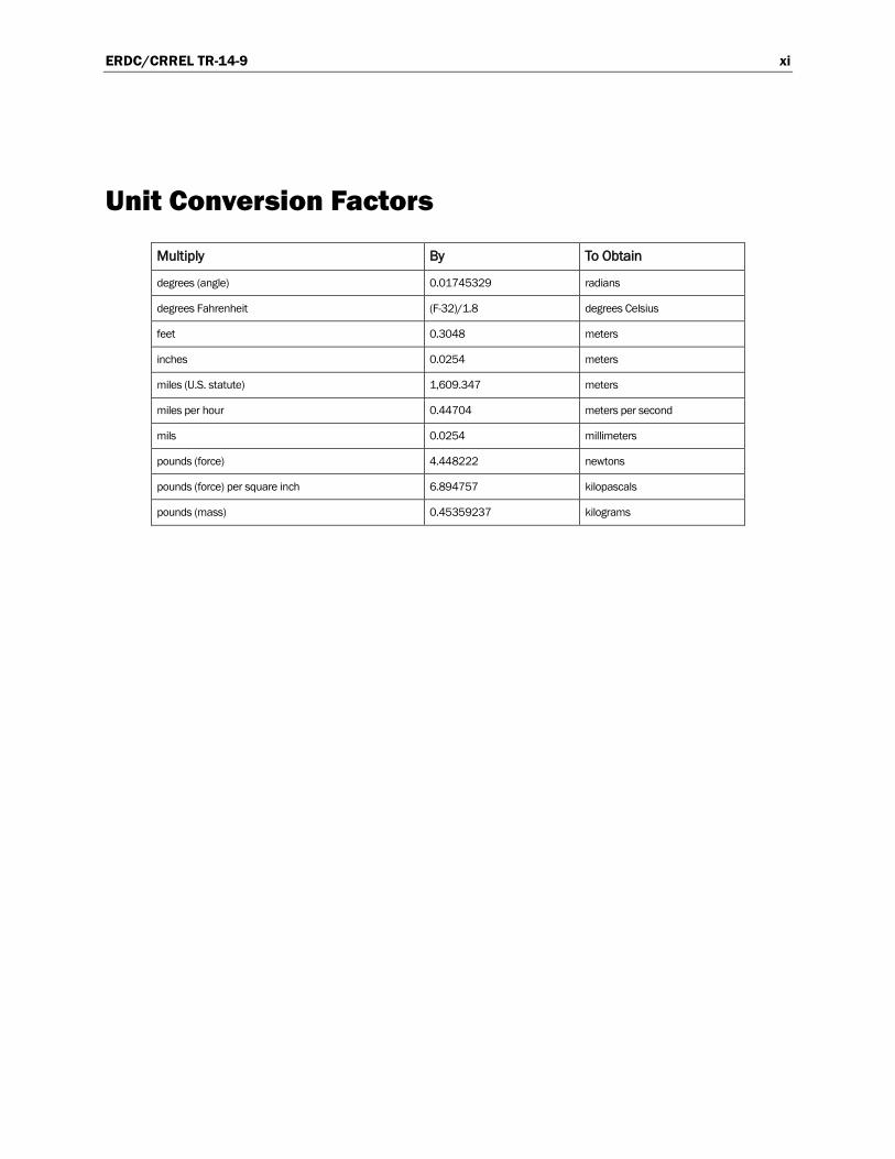
Unit Conversion Factors
Multiply By To Obtain
degrees (angle) 0.01745329 radians
degrees Fahrenheit (F-32)/1.8 degrees Celsius
feet 0.3048 meters
inches 0.0254 meters
miles (U.S. statute) 1,609.347 meters
miles per hour 0.44704 meters per second
mils 0.0254 millimeters
pounds (force) 4.448222 newtons
pounds (force) per square inch 6.894757 kilopascals
pounds (mass) 0.45359237 kilograms

ERDC/CRREL TR-14-9 xii
ERDC/CRREL TR-14-9 1
1 Introduction
1.1 Issue
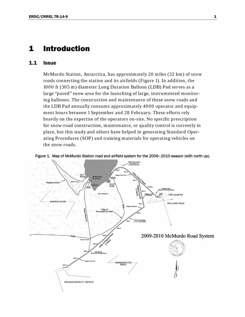
McMurdo Station, Antarctica, has approximately 20 miles (32 km) of snow roads connecting the station and its airfields (Figure 1). In addition, the 1000 ft (305 m) diameter Long Duration Balloon (LDB) Pad serves as a large “paved” snow area for the launching of large, instrumented monitor-ing balloons. The construction and maintenance of these snow roads and the LDB Pad annually consume approximately 4000 operator and equip-ment hours between 1 September and 28 February. These efforts rely heavily on the expertise of the operators on-site. No specific prescription for snow-road construction, maintenance, or quality control is currently in place, but this study and others have helped in generating Standard Oper-ating Procedures (SOP) and training materials for operating vehicles on the snow roads.
Figure 1. Map of McMurdo Station road and airfield system for the 2009–2010 season (with north up).

ERDC/CRREL TR-14-9 2
During the austral summer, McMurdo snow roads are subjected to warm summer air, which can be above freezing for several days at a time. Above freezing air temperatures cause severely reduced road strength, compound snow-road construction and maintenance challenges, and make the snow roads and LDB Pad more susceptible to failure. Depending on tempera-tures and other factors, in some years, the snow roads can fully support wheeled traffic for the entire summer season; and in other years, wheeled vehicle traffic must be severely reduced and sometimes becomes impossi-ble. The cost of snow-road failure is significant. In the worst case, nearly all transport of personnel and supplies to and from aircraft servicing McMurdo must be by a few specialized over-snow vehicles, such as the Foremost Deltas, or by towing with tracked vehicles.
1.2 Background and approach
The US Army Cold Regions Research and Engineering Laboratory (CRREL) in Hanover, NH, previously studied the processes used to pre-pare and maintain the McMurdo Station snow roads. Researchers wit-nessed activities from December 2002 to January 2003 and monitored ex-isting snow-road strength, maintenance, and vehicle fleet operations. Shoop et al. (2009) summarized this work; and Shoop et al. (2010) details it further. Shoop et al. (2010) also contains a literature review of snow-road construction methods, background on snow compaction and age hardening, and a summary of McMurdo’s historic snow-road construction and maintenance guidelines developed by the U.S. Navy. That CRREL re-port recommended the development of a modern snow-road construction and maintenance program, which evolved into the Snow Roads and Transportation (SRT) program.
As part of the SRT program, we developed a test plan to evaluate the im-pact of different types of vehicles on the snow roads under various weather and road conditions. As this type of testing had not been previously con-ducted on snow roads or using these types of vehicles, similar studies of military vehicle impacts on Army training lands (Affleck et al. 2004; Althoff and Thien 2005; Anderson and Shoop 2005; Ayers 1994; Ayers et al. 2004; Haugen 2002) and of low impact military tires (Ayers et al. 2006) provided guidance for test procedures.
Our report documents the detailed vehicle impact experiments performed 16–20 December 2009 with the initial evaluation of the measurement techniques presented in Shoop et al. (2013). The work included several

ERDC/CRREL TR-14-9 3
types of testing to explore the methods and measurement techniques needed to capture the impact of different vehicles on the snow roads and on other prepared snow surfaces (i.e., the LDB Pad).
With four vehicles, we performed three basic types of tests: spiral or circle test patterns to investigate the effect of turning radius; straight-line accel-eration, constant speed, and deceleration; and road course tests, which al-lowed both turns and speed variation. The spiral, circle, and straight-line tests were conducted on the LDB Pad, which offered a large, smooth, and uniform surface. Conversely, the road course was located on sections of existing snow roads and comprised a variety of curves and surface rough-ness and was therefore more characteristic of the actual road conditions.
We took initial strength measurements to characterize the test sites. We drove test patterns with several vehicles and then took rut width and depth, adjacent snow pile height and width, and snow strength measure-ments in and between the vehicle tire tracks (ruts) to determine how vehi-cle and driving parameters, such as speed, acceleration, deceleration, and turning radius, affect the snow-road surface.
Daily station operations, which have priority, limited the availability of ve-hicles, personnel, and locations for use for in the testing program and thus reduced the scope of the experiments. However, we did complete a sub-stantial number of tests and measurements. Table 1 summarizes the indi-vidual tests, which are also described in more detail later in the report.

ERDC/CRREL TR-14-9 4
Table 1. Snow-road vehicle-impact testing program, December 2009.
Date Test Vehicle Field
Test # Location Data 16 Dec. Spiral
Counterclockwise at 15 mph (24 kph) Fleet Operations
Truck (Denman tires)
A1 LDB Pad Small Clegg, rut width and depth, pile width and height
16 Dec. Circle Counterclockwise at 23 mph (37 kph) Radius = 100 ft (30.5 m)
Fleet Operations Truck
(Denman tires)
A2 LDB Pad Small Clegg, rut width and depth, pile width and height
16 Dec. Straight Line Acceleration Constant Speed at 25 mph (40 kph) Deceleration
Fleet Operations Truck
(Denman tires)
A3 LDB Pad Small Clegg
16 Dec. Spiral Counterclockwise at 15 mph (24 kph)
Fleet Operations Truck
(Denman tires)
A4 LDB Pad No measurable ruts
16 Dec. Straight Line Acceleration Constant Speed at 25 mph (40 kph) Deceleration to 0
Fleet Operations Truck
(Denman tires)
A5 LDB Pad No measurable ruts
16 Dec. Straight Line Acceleration Constant Speed at 20 mph (32 kph) Deceleration
Fleet Operations Truck
(Denman tires)
A6 LDB Pad Small Clegg
17 Dec. Spiral Counterclockwise at 15 mph (24 kph)
Van 206 (Cepek tires)
B1 LDB Pad Medium Clegg, rut width and depth, pile width and height
17 Dec. Spiral Counterclockwise at 15 mph (24 kph)
Van 213 (TRXUS tires)
B2 LDB Pad Medium Clegg, rut width and depth, pile width and height
17 Dec. Straight Line Constant Speed 25 mph (40 kph), 6 passes
Van 213 (TRXUS tires)
B3 LDB Pad Medium Clegg, rut width and depth, pile width and height
17 Dec. Straight Line Constant Speed 25 mph (40 kph), 6 passes
Van 206 (Cepek tires)
B4 LDB Pad Medium Clegg, rut width and depth, pile width and height
17 Dec. Straight Line Acceleration to Constant Speed of 20 mph (32 kph) or 25 mph (40 kph)
Fleet Operations Truck
(TRXUS tires)
B5 LDB Pad Medium Clegg, rut width and depth, pile width and height
20 Dec. Circle Clockwise Radius = 500 ft (152.4 m)
Foremost Terra Bus
C1 LDB Pad Medium Clegg, rut depth and width
20 Dec. Circle Clockwise Radius ≤ 500 ft (152.4 m)
Foremost Terra Bus
C2 LDB Pad No measurable ruts
20 Dec. Road Course 17 laps
Foremost Terra Bus
C3 Road Course
Medium Clegg, rut width and depth, pile width and height
20 Dec. Road Course 21 laps
Foremost Delta C4 Road Course
Medium Clegg, rut width and depth, pile width and height
20 Dec. Circle Clockwise Radius = 300 ft (91.4 m)
Foremost Delta C5 LDB Pad Medium Clegg, rut depth and width

ERDC/CRREL TR-14-9 5
2 Equipment
2.1 Snow strength measurements
We used two instruments to characterize the test sites prior to testing and to measure the impact of the vehicle on the snow strength after testing. We used the Rammsonde Snow Penetrometer to measure a strength profile for site characterization and used the Clegg Impact Hammer (Clegg) to measure the integrated strength of the road surface before and after test-ing. The Clegg measurements helped us to determine if the vehicle traffic changed the snow either through compaction or by weakening, through breaking, the bonds of the prepared snow surface. We assessed the Clegg strength after the vehicle maneuvers by taking measurements both in and between the ruts of the vehicle tire tracks. For additional details regarding the use of the strength instruments, see Shoop et al. (2010).
2.1.1 Rammsonde Snow Penetrometer
The U.S. Army adapted the Rammsonde, seen in Figure 2, from an in-strument originally used in the Swiss Alps for estimating avalanche dan-ger. The Rammsonde used for measuring the strength of the compacted snow roads and runways has a cone with a diameter of 0.94 in. (2.4 cm), a height of 1.54 in. (3.9 cm), a total length of 1.97 in. (5 cm), and a 60° coni-cal tip, which is smaller than what is commonly used in avalanche studies*. The smaller cone is more sensitive to the range of snow strength seen on snow roads and is also easier to use (both to insert and to remove) on compacted snow surfaces. The Rammsonde hardness number, R, is an in-dex that indicates the snow’s resistance to the vertical penetration (in kilo-grams force, kgf). The hardness reading is calculated from the number of hammer blows (drops) required to penetrate a measured distance. The penetration force is obtained using a slide hammer of specific weight dropped from a measured height.
* The original, larger device is a cone penetrometer consisting of a 0.79 in. (2 cm) diameter aluminum
shaft with a 60° conical tip, a guide rod, and a drop hammer. The cone has a diameter of 1.57 in. (4 cm) and height of 1.38 in. (3.5 cm); the total length of the penetrometer cone element (to the begin-ning of the shaft) is 3.94 in. (10 cm).

ERDC/CRREL TR-14-9 6
Figure 2. Rammsonde snow hardness profiling measurement.
2.1.2 Clegg Impact Hammer
We measured snow surface strength by using a Clegg (Figure 3). The Clegg consists of a cylindrical mass hammer that is dropped within a guide tube from a set height. The standard Clegg uses a 9.9 lb (4.5 kg) hammer mass. In this testing program, we used two other hammer weights, the medium Clegg at 5.0 lb (2.25 kg) and the small Clegg at 1.1 lb (0.5 kg); and we de-termined that in many cases the 9.9 lb (4.5 kg) hammer was too heavy. However, we found that the medium 5.0 lb (2.25 kg) Clegg was the most suitable for characterizing the snow-road strength, but we used both the small and medium Cleggs in this study, depending on availability. Table 1 specifies the Clegg used for each test. All of the Clegg hammers have the same diameter: 17/8 in. (4.76 cm). Clegg (2011) provides a more detailed analysis of the 5.0 lb (2.25 kg) Clegg, and Shoop et al. (2012) compares the three Clegg sizes and their use on the snow roads.
The Clegg is equipped with an accelerometer that measures the peak de-celeration on impact. For the snow roads program, the hammer is dropped five times at each location and the readings for each drop are recorded as the Clegg Impact Value (CIV). Although the fourth drop CIV reading is usually used for soil-strength calculations, we used an average of the third, fourth and fifth drop values for the snow strength in this study. Further analysis of Clegg data in Shoop et al. (2012) indicates that the Clegg value from the third drop alone is sufficient for analysis purposes and could also have been used. Finally, we analyzed the first drop value and determined

ERDC/CRREL TR-14-9 7
that it was more of an indicator of untouched or untamped snow surface strength.
Figure 3. Clegg Impact Hammer measuring road surface strength.
2.2 Impact measurements
Using the undisturbed snow as the elevation datum, after each test we measured with a straight edge cross piece and a meter stick or steel tape the width and depth of the ruts from each tire track, left and right (Figure 4). With a similar procedure, we measured the adjacent pile heights and widths (Figure 5). These types of measurements duplicate those used for soil surfaces, such as described in Haugen (2002). Figure 5 also shows more detailed rut profile measurements taken using a profilometer, but these were time consuming. The analysis of the profilometer data has since been automated, and these types of measurements should be considered for future studies.

ERDC/CRREL TR-14-9 8
Figure 4. Rut depth was measured from the original snow surface to the deepest part of the rut.
Figure 5. The height of the pile on the side of the rut was measured from the undisturbed snow surface.
2.3 Test vehicles
Table 2 lists the four vehicle types (shown in Figures 6 through 9) used during the vehicle impact testing. The two vans, 206 and 213, are the same make and model and are therefore considered identical. We tested both the vans and the fleet operations pickup truck with two different types of tires. The Deltas at McMurdo have either a smooth tread or a more aggres-sive chevron tread. All of our testing was done using the Deltas with the smooth tread tires, which are used in the wheeled vehicle lanes of the snow roads. The Deltas with the chevron tires are usually used to move cargo and stay in the track vehicle lanes.

ERDC/CRREL TR-14-9 9
When the temperatures are cooler and the roads are hard, the vans are much faster and provide a more comfortable passenger ride to and from the airfields. The Terra Bus and Delta can handle many more people and cargo and are the primary people movers for the snow-road transportation system, especially during warm weather when their high flotation tires al-low greater over-snow mobility.
Table 2. Test vehicle information.
Vehicle Vehicle Weight
kN (lbf) Tires Tire Pressure kPa (psi)
LF RF LR RR Fleet Operations Truck 144, Ford F350
27.9 (6262) Denman Ground Hawg II steel belted radial (old tires), 36 × 14.5 R16.5LT
138 (20)
124 (18)
152 (22)
145 (21)
Fleet Operations Truck 144, Ford F350
27.9 (6262) Interco TRXUS STS (new tires) 36 × 14.50 R16.5LT
125 (18)
131 (19)
138 (20)
138 (20)
Van 206, Ford E350 41.4 (9300) Cepek Fun Country (old tires) 40 × 17 R16.5 LT
152 (22)
103 (15)
131 (19)
117 (17)
Van 213, Ford E350 41.4 (9300) Interco TRXUS M/T (new tires) 38.5 × 14.5 R17LT
103 (15)
96 (14)
103 (15)
93 (13.5)
Foremost Terra Bus “Ivan” 298.0 (67000) Terra-Tire: Tubeless Nylon 66 × 44.00-25NHS
172 (25)
165 (24)
172/138 (25/20)
172/165 (25/24)
Foremost Delta “Gale”* 186.8 (42000) Terra-Tire: Tubeless Nylon 66 × 44.00-25 NHS
83 (12)
152 (22)
131 (19)
110 (16)
*Tire pressures adjusted for a uniform section deflection height.
Figure 6. Ford F350 fleet operations truck.

ERDC/CRREL TR-14-9 10
Figure 7. Ford E350 Van
Figure 8. Foremost Terra Bus.
Figure 9. Foremost Delta.

ERDC/CRREL TR-14-9 11
3 Test Sites
3.1 Locations
We used two areas for the vehicle impact testing: the LDB Pad and a sec-tion of the existing snow-road system. Figure 10 shows imposed on a high-resolution satellite photo the locations of the LDB Pad (the red circle on the left) and the triangular road course test section (on the right) within the McMurdo snow-road system. All of the test areas had initially smooth and level surfaces even though parts of the road course was cut through sastrugi (snow ridges formed by wind) as can be seen on the imagery in Figure 10.
Figure 10. Satellite image of the LDB Pad (red circle) and road test course (yellow) with north downward (29 October 2009 WorldView Satellite at 0.5m resolution)
3.1.1 Long Duration Balloon Pad
The LDB Pad is a 1000 ft (305 m) diameter pad used to launch high-atmosphere, long-duration balloons with various atmosphere and space payloads. The LDB Pad is maintained continuously from October to mid-December to provide a very smooth and stable platform for the heavy equipment used during balloon launches. Once the balloon experiments were completed for the season, the LDB Pad provided a smooth, uniform surface on which to conduct comparative vehicle impact tests. Tests on the LDB Pad included the spiral and circle tests with all four vehicles and the
Note: In this image, north is downward.

ERDC/CRREL TR-14-9 12
acceleration, constant speed, and deceleration tests with the fleet opera-tions truck and the vans. Both of the large vehicles, the Terra Bus and the Delta, had difficulties performing the spiral maneuver with tight turning radii, so the spiral test was replaced by a breakout circle test for these two vehicles.
3.1.2 Road course
In addition to the scripted tests on the LDB Pad and to obtain information during a more realistic operating scenario, we developed a small road course at the junction of Williams and Pegasus cut-off roads (Figure 10). Only the Terra Bus and Delta were used on the road course.
3.2 Initial site characterization
Prior to vehicle testing, we characterized the snow surface strength of the LDB Pad on 16 December 2009. We measured the snow surface strength at seven points, labeled LDB Pad and LDBP1–LDBP6 on Figure 11, cover-ing the primary area of vehicle testing by using the medium size Clegg. At each point, we took three to five measurements (of five drops each) within a 10 ft (3.05 m) radius for each sampling location.
Figure 11. Clegg and Rammsonde strength-measurement test points for the LDB Pad and for the road course.

ERDC/CRREL TR-14-9 13
We averaged the Clegg measurements for each sampling location using (1) the first drop, which is indicative of the strength of the undisturbed snow, and (2) the average of the third, fourth, and fifth drop values, which are indicative of the snow under the vehicle tires (Figure 12). Shoop et al. (2012) provides a thorough explanation and reasoning behind the use of the Clegg, especially for snow. The statistics (average and standard devia-tion) for Clegg values from the LDB Pad test points are shown on the right-hand side of the graph. The average Clegg values were 7.5 (first drop) and 12.4 (average of drops 3–5). Interestingly, the standard deviations of the two different calculations (first drop and average of drops 3 to 5) are near-ly the same value, approximately 2.0.
Figure 12. Medium Clegg data for the LDB Pad initial site characterization.
To compare between the three sizes of Clegg hammer, small, medium, and large measurements were taken at one location. This information is re-ported in Shoop et al. (2012).
The Clegg values taken along the road course are more variable as ex-pected for the multiple types of road surfaces involved, which are groomed differently and have been exposed to different levels of vehicle traffic. We

ERDC/CRREL TR-14-9 14
used these measurements to compare the strength before and after vehicle trafficking, and Section 6: Road Course Tests presents these comparisons.
We also took profiles of road strength at both the LDB Pad and at the road course by using the Rammsonde. Figure 11 shows the locations of these measurements, and Figures 13 and 14 graph the Rammsonde values. We used these values primarily to assess and to document the snow strength below the surface, while the Clegg is a surface strength measurement. Alt-hough the subsurface strength could certainly be impacted by the heavier vehicles during the road course testing, the Rammsonde was not used be-fore and after testing to measure the test impact; it was only used to char-acterize the site to document differences based on the location and vehicle lane and overall variability of the pad and road course. The Clegg was much quicker and easier to use to assess surface strength changes.
Figure 13. LDB Pad strength profile.

ERDC/CRREL TR-14-9 15
Figure 14. Road course strength profile from the Rammsonde. Data taken in the Delta lane are in blue; Terra Bus lane data is red. The measurement
locations are shown in Figure 11.

ERDC/CRREL TR-14-9 16
4 Spiral and Circle Tests
4.1 Testing
Spiral testing involved driving either the fleet operations truck or one of the two vans in an inward decreasing radius spiral starting at an outside radius of 100 ft (30.5 m). We first measured the outside of the spiral and marked it on the LDB Pad surface to serve as a guide for the driver. Every attempt was made to maintain a constant speed and produce a regular spi-ral. At points where the spiral crossed a marked “radius,” we took meas-urements of the tire track rut depth and width, resulting snow pile height and width, and the surface strength in and between the ruts. The number of times a vehicle crossed the radius is reported as “x=4,” for this example, indicating the vehicle crossed the radius four times as Figure 15 shows. At these points, we measured the distance to the left and right tire track from the center point of the spiral.
Figure 15. Counterclockwise spiral test configuration.
At the end of the spiral tests, we performed a circle test around the outside of the spiral as space and safety allowed. For this test, the vehicle drove in the circle at gradually increasing speed until it began to slide. This type of test is also called a circle breakout test and can be used to measure friction as well.
“radius”
Spiral x=4
Direction of travel for Fleet Operations Truck and Van tests
Note: The Terra Bus and Delta traveled in clockwise circles

ERDC/CRREL TR-14-9 17
For the Terra Bus and the Delta, even when starting with a much larger radius, it was impossible to drive the decreasing radius spiral within the limited space. Therefore, we used circles of a large diameter (500 ft [152 m] for the Terra Bus and 300 ft [91 m] for the Delta) for the outside of the spiral. We again marked the circles on the ground to provide guidance to the driver.
4.1.1 F350 truck spiral and circle tests (A1, A1, and A4)
Using the fleet operations truck with older Denman tires, spiral test A1 completed four crossings of the radius. The furthest set of tracks measured was 82 and 88 ft (25.9 and 26.8 m) from the spiral center point, left and right tires, respectively. The fleet operations truck drove at no less than 12 mph (19 kph) until the inner spiral where it drove at 10 mph (16 kph).
Figure 16 shows a comparison between the first drop measurement and the average of drops three through five for the small (1.1 lb [0.5 kg]) Clegg hammer. For most cases, the snow was weaker in the tire tracks because the surface sheared during a turning maneuver. This is particularly true during tight turns where the difference between the inside and outside track values was greatest. The trends were similar for the two calculation methods, as they were in Figure 12; therefore, we will use the third to fifth drop average for the remainder of the discussion.
Figure 16. Clegg surface strength measurements for counterclockwise (left turn) spiral test A1 with the fleet operations truck (old Denman tires).

ERDC/CRREL TR-14-9 18
Figure 17 shows the tire track rut depth and width and the corresponding accumulated snow pile height and width. We expect more disturbance on the right side of the vehicle because the vehicle weight shifts to the right during counterclockwise turning. While the rut data does not always re-flect this, the right pile is consistently the largest as snow it pushed to the right side of both wheel paths.
Figure 17. Rut and pile measurements for counterclockwise spiral test A1 with the Fleet Operations F350 Truck (old Denman tires).
During spiral test A4, the fleet operations truck, traveling at 15 mph (24 kph), experienced some slipping but left no appreciable rutting. Therefore, we did not take any rut, pile, or Clegg measurements.
Test A2 was a circle test occurring outside the maximum 88 ft (26.8 m) radius of the spiral test track. The same fleet operations truck from the previous two tests drove at approximately 23 mph (37 kph) and experi-enced sliding at the outer edge of the circle, indicating that it was operat-ing close to the maximum value of lateral friction of this surface. Because the circle test differed significantly in speed from the spiral tests, test A2

ERDC/CRREL TR-14-9 19
results are presented graphically in Section 4.2.2: Comparison between vehicles.
4.1.2 E350 van spiral tests (B1 and B2)
Figures 18 and 19 present the data from spiral test B1, driven counter-clockwise with Van 206 with older Cepek tires. In this test, the snow is generally weaker (strength is lower) under the outside (right) tire track due to the additional weight crushing or shearing the snow during the turn. This effect is particularly noticeable at the larger turning radius where the vehicle was traveling at a higher speed (resulting in greater weight transfer to the outside tires).
Figure 18. Clegg snow surface strength measurements for counterclockwise spiral test B1 with Van 206 (old Cepek tires).

ERDC/CRREL TR-14-9 20
Figure 19. Rut and pile measurements for counterclockwise spiral test B1 with Van 206 (old Cepek tires).
Van 213 had new TRXUS tires for spiral test B2. The driver reported that he could definitely feel a difference with the new tires and that they were “biting better.” Figures 20 and 21 present the data from this test. These show the inside (left) track being generally weaker snow (lower Clegg read-ing). This is the opposite of what we would expect; and the undisturbed snow readings, taken between the tire tracks, were often weaker than in the tire tracks. We speculate that the new low-impact tires could spread the weight out better and compact the snow under the additional weight rather than crush or shear it. Additional testing should be done to explore this further.

ERDC/CRREL TR-14-9 21
Figure 20. Clegg snow surface strength measurements for counterclockwise spiral test B2 with Van 213 (new Interco
TRXUS M/T tires).
Figure 21. Rut and pile measurements for counterclockwise spiral test B2 with Van 213 (new Interco TRXUS M/T tires).

ERDC/CRREL TR-14-9 22
4.1.3 Terra Bus and Delta circle tests (C1 and C5)
For circle test C1, the driver attempted to hold the Terra Bus at a constant radius of 500 ft (152 m) on the marked circle, driving clockwise in fifth gear. The bus completed six circles. Following the test, we took Clegg and rut and pile measurements.
We attempted a tighter radius circle and a higher speed for test C2 with limited success. The drive path was difficult to keep circular, yielding in-consistent vehicle loading on the surface. Therefore, we took no measure-ments.
In circle test C5, the Delta personnel carrier drove in clockwise circles with a 300 ft (91 m) radius. The steering and wheel base of the Delta allowed this tighter circle to be driven successfully (and safely). Again, following the test, we took Clegg and rut and pile measurements.
Figure 22 presents the medium Clegg (5.0 lb [2.25 kg]) data from tests C1 and C5. The ruts left in these tests were subjectively observed to be “soft” (lower snow surface strength), but there is no consistent trend in the ruts being softer (from more shearing) or harder (from compaction) than the surrounding snow or from one side of the vehicle to the other.
Figure 22. Average medium Clegg reading of surface strength measurements for clockwise circle tests with the Terra Bus (C1) and the
Delta (C5).

ERDC/CRREL TR-14-9 23
The tires for both vehicles are the same make and diameter. However, it appears that the lighter weight Delta was shearing the snow because of a tighter radius circle, in comparison to the heavier Terra Bus driving at slower speeds and at a larger diameter path, which was compacting the snow. We cannot be certain whether the Clegg results from these two tests are due to compaction (making the snow stronger) or shearing under the tires (weakening the snow) because the differences are within the range of the overall variability of the LDB Pad snow surface (shown earlier to be ± 2.0 Clegg units, Figure 12).
4.2 Analysis
4.2.1 Effect of the turning radius on vehicle impact
In test A1, using the fleet operations truck (Figure 17), the tire-track rut depth decreased with increasing distance from the spiral’s center. We can also state this as rut depth decreased as turning radius increased, or a smaller turning radius or sharper turn will result in a larger rut. Figure 23 illustrates this even more clearly. Pile heights and widths show similar trends (piles are higher and wider at a tighter turning radius).
Figure 23. Rut measurement from spiral maneuver A1 using the fleet operations truck (older Denman tires).
Because the rut and pile result from material the vehicle displaces either through compaction or mass movement, an estimate of the volume of the material moved could provide a more realistic measure of impact. We can

ERDC/CRREL TR-14-9 24
quantify the total vehicle impact (TVI) in terms of rut depth (RD) and rut width (RW), and for the piles alongside the rut, the pile height (PH) and pile width (PW). From these measurements, we can calculate a total im-pact that represents the cross sectional area of all of the snow displaced by the vehicle (rut area plus pile area). Equation (1) gives the TVI value for both the left (subscript L) and right (subscript R) vehicle tracks (assuming roughly triangular snow piles):
TVI = RDL+R × RWL+R + ½ (PHR × PWR) + ½ (PHL × PWL) (1)
The spiral test A1 rut and pile data were used to calculate the TVI. Figure 24 plots the TVI with distance from center. Note that the impact severity increases greatly to TVI values over 12 in.2 (80 cm2) for turning radii less than 30 ft (10 m). An exponential decline in impact with distance is similar to findings from tests with military vehicles on training lands (Ayers et al. 2004; Affleck et al. 2004). This trend clearly indicates that a larger turning radius causes less rut impact. This information can aid in designing roads with gentle curves and reducing or eliminating tight turns while driving, reducing road damage.
Figure 24. Impact of fleet operations truck.

ERDC/CRREL TR-14-9 25
4.2.2 Comparison between vehicles
Because the circle tests were done with multiple passes and involved some vehicle sliding, the rut depths and widths in the tire tracks were not always clearly defined. Nonetheless, the data that could be measured we assem-bled into Figure 25, showing the rut depths measured for each of the circle tests (A2, C1, and C5). We should note that the fleet operations truck trav-elled the circles counterclockwise while the Terra Bus and Delta were driv-en in clockwise circles. Ideally, all tests would have been in both direc-tions, but space and time were limited.
Figure 25. Circle test rut depths for the fleet operations truck, the Delta, and the Terra Bus.
Section 6 provides further vehicles comparisons from road course data.
We used the disturbance measurements to calculate the TVI in Table 3. While the Delta shows the greatest impact for this set of tests, the tests were conducted for different radius circles and vehicle speeds, making a direct comparison difficult. The aim of this study was to determine how to run the test and what test radius and speeds would work well. Now that we have an idea of the capabilities of these vehicles, in the future we would choose a single speed and radius to use for all vehicles in the test set if comparison between vehicles was the objective. The vehicle set here com-prises a wide range of vehicles used on the snow roads although over the last two years, even larger vehicles are now present at McMurdo.

ERDC/CRREL TR-14-9 26
Table 3. Relative vehicle impact resulting from the circle tests.
Vehicle Circle Radius (m) TVI (cm2) Delta 28 270 Fleet Ops Truck, F350 30 47 Terra Bus 35 70
4.2.3 Comparison of TRXUS and Cepek tires
We can use the data from spiral tests B1 and B2 to evaluate the perfor-mance of the new and old tires. A comparison of Figures 19 and 21 shows the rut and pile disturbances to be generally greater for the Cepek tires. Figure 26 illustrates this directly by showing the rut depth measurements from the spiral test conducted using van 213 with the new TRXUS tires (test B1) and van 206 with the old Cepek tires (test B2). In nearly all cases, the Cepek tires created the larger ruts, especially at the tighter turning ra-dius. During turning maneuvers, the new tires were clearly an improve-ment and showed nearly half the rut-depth impact of the old tires.
Figure 26. Van spiral tests with different tires.
The Clegg data from Figure 18 and Figure 20 show an increase in snow strength in the ruts of the TRXUS tires while the snow sometimes lost strength under the Cepek tires. Likely, this is because the TRXUS tires dis-tribute the loading more evenly across the contact patch, resulting in an overall lower contact stress without stress concentrations. They did not shear the snow surface but rather compacted it while the Cepek tires tend-ed to shear and fail the snow surface resulting in more disturbance and lower snow strength. These are general trends but could be clarified with more testing to generate enough data for a statistical analysis now that we have generated appropriate test procedures.

ERDC/CRREL TR-14-9 27
5 Straight Line Tests (acceleration, constant speed, and deceleration)
5.1 Testing
The acceleration, constant speed, and deceleration tests took place on the LDB Pad and used the fleet operations F350 truck with the Denman TRXUS STS tires and the E350 Vans with old Cepek and the new TRXUS M/T tires). We drove the vehicles in a straight line bisecting the spirals and circles. The straight line tests consisted of three portions:
1. Accelerating the vehicle over a set distance to a specified speed. Because the distance was constant, the acceleration varied slightly depending on the end target speed.
2. Holding the vehicle constant at the specified speed for a given distance. 3. Braking the vehicle using full (but not locked) braking to a stop.
The target speeds for the constant speed portion of each test were 20 and 25 mph (32 and 40 kph). We measured the depth and width of the tire track ruts and the width and height of the snow piles accumulated next to the tire tracks. Figures 27 and 28 give the rut and pile measurements from these tests.
For the constant speed tests (Figure 27), the imprint from the 20 mph (32 kph) test was clear with tread patterns discernible for most of the track. At 25 mph (40 kph), the tire track was deeper than the tracks made at slower speeds; and the print was obscured by the tire shearing the surface of the snow. The acceleration to 25 mph (40 kph) consistently showed higher impact (higher rut depth, rut width, and pile width) than the acceleration to 20 mph (32 kph) test, but this trend was not consistent for the constant speed portion of the test.

ERDC/CRREL TR-14-9 28
Figure 27. Rut and pile measurements for test B5, which used the fleet operations truck (new Interco TRXUS STS tires) with straight line
acceleration and a constant speed.
Figure 28. Rut and pile measurements for straight line, constant speed tests B3, B4, and B5 (25 mph [40 kph], 6 passes).
The Clegg data shows a decrease in the snow strength in the tire tracks for nearly all cases. The exceptions were inconsistent between tires, vehicles,
0
5
10
15
20
25
30
35
40
45
50
Rut Depth Rut Width Pile Height Pile Width
cm
Measurement
Fleet Ops F350 Truck (TRXUS STS tires)Van 213 (new TRXUS M/T tires)
Van 206 (old Cepek Tires)

ERDC/CRREL TR-14-9 29
or test type; but the right rut was stronger than the undisturbed snow for the F350 with Denman tires (deceleration test), the F350 with TRXUS (ac-celeration test), and the E350 Van with Cepek tires (constant speed). No explanation is clear for this unless perhaps the right side of the test area was stronger in some sections of the test pad. The full set of Clegg data for these tests is in Appendix A.
5.2 Comparison of tires
Figure 28 provides a comparison of the three of the tires used. The old Cepek tires produced a higher impact than either of the TRXUS tires, con-firming that the new TRXUS M/T replacement tires do in fact lower the impact of the vehicle on the snow roads. Observationally, we noted that Van 213 with new tires bounced more, which could create a higher impact on the roads where bumps and dips are more common than on the LDP Pad where the testing was performed; and the fleet operations truck creat-ed some small washboarding. By visual inspection, Van 213 with new tires did slightly less damage to the snow surface during its acceleration test and also made clear track prints while Van 206 (old tires) threw more snow; and the tires sheared the surface, obliterating the tread print.
Figure 29 shows the Clegg measurements for the TRXUS and Cepek tires on the vans. Both of these tests were conducted with the van traveling at 25 mph (40 kph). The snow in the tire tracks was weaker than the undis-turbed snow (i.e., more damaged) from both of the tire types. However, the snow was weakest in the ruts of the Cepek tires. The decrease in strength from the undisturbed snow (between the tire tracks) to the strength in the ruts was greatest for the new TRXUS tires, though the snow was stronger in that area of the pad.

ERDC/CRREL TR-14-9 30
Figure 29. Comparison of Clegg measurements from 25 mph (40 kph) constant speed tests for the vans equipped with new and old tires.
16
9.29.4
6.4
0
2
4
6
8
10
12
14
16
18
Van 213 (new TRXUS M/T tires) Van 206 (old Cepek Tires)
Measurement Point
Between Tracks
In Track Average
2.25
kg
(5.0
lb) C
IV

ERDC/CRREL TR-14-9 31
6 Road Course Tests
For more realistic operational conditions, we also drove the Terra Bus and Delta in a road course test. The road course tests used a short section of the active snow road to the LDB Pad along with an unused section of snow road that resulted from rerouting the snow roads earlier in the season. Figure 30 shows a schematic of the test course and the lanes used by each vehicle. We mounted global positioning system (GPS) tracking sticks in these vehicles during the test runs and analyzed after the tests the tracks they recorded. It was immediately obvious that the Delta was able to main-tain a fairly consistent speed during the laps while the Terra Bus had vary-ing lap times due primarily to the increasingly rough road surface it was creating (Figure 31). Knuth and Shoop (2010) describe fully the tracking sticks and their use in this type of testing.
Figure 30. Schematic of the road course test.

ERDC/CRREL TR-14-9 32
Figure 31. Road course lap times for the Terra Bus and Delta (Knuth and Shoop 2010).
6.1 Terra Bus
The Terra Bus completed 17 laps around the road course before the course became too rough to continue the test. The driver indicated that he achieved his maximum speed possible in sixth gear on the straight stretch-es but had to slow and take the turns in fifth gear.
Figure 32 shows measurement locations and field notes from this testing. Letters A through H indicate rut and pile measurements, and the letter-number combinations TB-1 through TB-13 are the locations of Clegg tests. Rutting that occurred in the straight stretches seemed to be more obvious in the left tire tracks, perhaps due to the added weight of the fuel tank on that side. After the third lap, the course surface was noticeably changed; the “bumpy” section was soft and slowed the vehicle down. After lap 10, the straightaway was still looked good; and the corners were not too deep-ly rutted but were slick. Final ruts were up to 21.7 in. (55 cm) deep and 59.0 in. (150 cm) wide. Figures 33 and 34 present the data of the medium Clegg snow-surface strength. The data for the two tracks are averaged in Figure 34 to allow comparison to the data from the Delta road test. Figure 35 shows rut and snow-pile measurements from the Terra Bus tire tracks.

ERDC/CRREL TR-14-9 33
Figure 32. Sketch of road course test notes (Terra Bus in red and Delta in blue) and rut measurement locations (not to scale).
Bumps
Start
Started as slight bump, which caused Terra Bus to bounce
New LDB Road Old LDB
Road
B
A
C
G
H
F
E
D
After 3 laps started to tear up: Terra Bus
After 12th lap, had to put Terra Bus in 5th gear at this location; after 15 laps making a new rut, reduced to 4th gear
Delta started slip-ping on lap 10; needed to use 3rd gear after lap 10
After 7 laps, not much surface im-pression and barely any fluff: Terra Bus
After 12th lap, had to put Terra Bus in 5th gear at this location
After 15th lap, had to put Terra Bus in 5th gear at this location
Washboarding: Terra Bus
Delta started slipping on lap 10; needed to use 3rd gear after lap 10

ERDC/CRREL TR-14-9 34
Figure 33. Measurements of the Clegg snow-surface strength for the Terra Bus road course test.
Figure 34. Measurements of the Clegg snow-surface strength for the Terra Bus road course test with in-track measurements averaged.

ERDC/CRREL TR-14-9 35
Figure 35. Rut and pile measurements for the Terra Bus road course test.
6.2 Delta
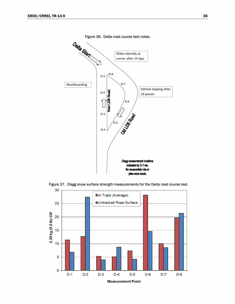
The Delta completed 21 laps in its road course test. The vehicle was driven in forth gear with the speed “maxed.” After 10 laps, we observed rutting only on corners; and it was not of a measurable depth. The straight stretches, however, became bumpier. After lap 14, the drivers noted that the corners began to feel like the surface was a washboard. After lap 15, the vehicle began sliding laterally at the corner near the starting point. Figure 36 shows Clegg surface strength measurement locations (D-1 through D-8) and additional field notes from this testing. Figure 37 presents the strength data measured. The Delta left no measurable ruts or piles, only tire imprints.
ERDC/CRREL TR-14-9 36
Figure 36. Delta road course test notes.
Figure 37. Clegg snow surface strength measurements for the Delta road course test.
D-8
D-7
D-6
D-5
D-4
D-3
D-2
D-1
Slides laterally at
corner after 15 laps
Washboarding
Vehicle slipping after
10 passes
ERDC/CRREL TR-14-9 37
6.3 Analysis
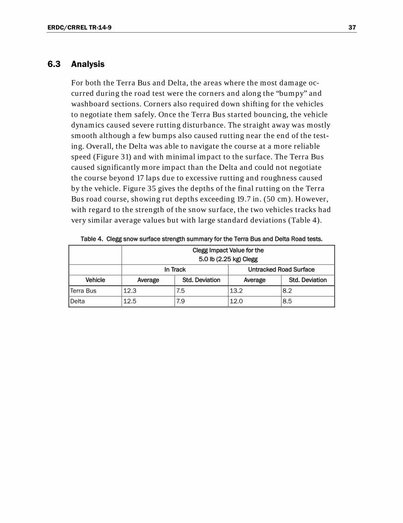
For both the Terra Bus and Delta, the areas where the most damage oc-curred during the road test were the corners and along the “bumpy” and washboard sections. Corners also required down shifting for the vehicles to negotiate them safely. Once the Terra Bus started bouncing, the vehicle dynamics caused severe rutting disturbance. The straight away was mostly smooth although a few bumps also caused rutting near the end of the test-ing. Overall, the Delta was able to navigate the course at a more reliable speed (Figure 31) and with minimal impact to the surface. The Terra Bus caused significantly more impact than the Delta and could not negotiate the course beyond 17 laps due to excessive rutting and roughness caused by the vehicle. Figure 35 gives the depths of the final rutting on the Terra Bus road course, showing rut depths exceeding 19.7 in. (50 cm). However, with regard to the strength of the snow surface, the two vehicles tracks had very similar average values but with large standard deviations (Table 4).
Table 4. Clegg snow surface strength summary for the Terra Bus and Delta Road tests.
Clegg Impact Value for the
5.0 lb (2.25 kg) Clegg In Track Untracked Road Surface
Vehicle Average Std. Deviation Average Std. Deviation
Terra Bus 12.3 7.5 13.2 8.2 Delta 12.5 7.9 12.0 8.5

ERDC/CRREL TR-14-9 38
7 Summary and Conclusions
During the austral summer, temperatures at McMurdo Station can be above freezing for several days at a time, resulting in the melting of road and runway infrastructure constructed of snow and ice. To make the best decisions regarding the construction, maintenance, and use of the snow roads, it is necessary to implement more formalized procedures and guid-ance and to monitor road maintenance, use, and conditions. As part of this, field data on the impact of different vehicle types on road conditions are useful. Therefore, during the austral summer of 2009–2010, we con-ducted an exploration of how best to assess and to quantify the impact of different vehicles on the road condition. We used four different vehicles (with various tires) for turning and straight-line maneuvers on a smooth prepared snow launch pad; and we used two of the larger transport vehi-cles on multiple passes on a test course made of existing snow roads.
The project served to determine the maneuvers and measures that quanti-fy the impact of different vehicles, tires, and operating procedures. This information can be used in decision making, to design test programs need-ed for purchases, or for snow road use guidelines. Measurements of the disturbance in terms of rutting and piles formed were helpful to determine speed and turning effects and which tires caused less damage to the sur-face. The road course provided a more operationally relevant test with compounded factors (turns, bumps, strength variations, etc.) and clearly distinguished which vehicle caused less impact and the types of maneuvers that cause the greatest impacts.
We can conclude the following specific results from this study:
1. Future snow-road construction should avoid tight turns to reduce rutting and damage to the road.
2. It is equally important to limit even small bumps and washboards, which can lead to larger rutting problems with continued vehicle passage.
3. Vehicle speed plays a large part in how well the snow roads hold up to use. Higher vehicle speeds cause more damage.
4. Accelerating slowly on the snow roads will aid in keeping a strong surface and reducing the effects of vehicles.

ERDC/CRREL TR-14-9 39
5. The new TRXUS tires showed reduced impact on the snow roads. To re-duce impact to the snow road, these or other low impact tires should be used for all of the trucks and vans.
6. The Delta was much gentler on the snow-road course than the Terra Bus.
Based on this study and follow-on discussions, CRREL, NSF, and McMur-do personnel jointly generated guidance for driving on the snow roads and incorporated it into the driver’s training program at McMurdo. Appendix B presents the full set of slides developed for explaining the impacts of driving on the snow roads. These slides were presented in full to the trans-portation section (ATO) at McMurdo, and a portion of the material was added to the McMurdo driver’s education program for everyone driving vehicles at McMurdo Station. The thoughtful adherence to these guide-lines helps preserve the snow roads, especially throughout the warm sea-son.
Recommendations for future work include the following:
1. Use the test methods and measurement techniques developed here to test the choice of tires and equipment for consideration of the best vehicle or tires for purchase to use on the snow roads.
2. Use the test methods and measurements developed to quantify the quality of the road surface, to rank maintenance equipment and procedures, and to improve construction and maintenance operations.
3. Develop a rutting and impact model specific to snow and snow roads, which incorporates speed and turning effects for vehicle impacts. Such a model could be used to determine or limit operation of certain vehicles or maneuvers (speeds) on the snow-road system.

ERDC/CRREL TR-14-9 40
References Affleck, R. T., S. Shoop, K. Simmons, and P. Ayers. 2004. Disturbance from off-road
vehicle during spring thaw. Proceedings of the International Symposium on Cold Regions Engineering, ed. D. W. Smith, D. C. Sego, and C. A. Lendzion, vol. 12. Reston, VA: American Society of Civil Engineers.
Althoff, P., and S. Thien. 2005. Impact of M1A1 main battle tank disturbance on soil quality, invertebrates, and vegetation characteristics. Journal of Terramechanics 42 (3–4): 159-176.
Anderson, A., and S. Shoop, eds. 2005. Assessing the Impact of Military Vehicular Traffic on Natural Areas. Journal of Terramechanics 42 (3–4): 143–158.
Ayers, P. 1994. Environmental damage from tracked vehicle operation. Journal of Terramechanics 31 (3): 173–183.
Ayers, P., C. Butler, A. Fiscor, C. Wu, Qinghe Li, and A. Anderson. 2004. Vehicle impact study at Fort Riley, Kansas, October 2004. Fort Riley, KS: Integrated Training Area Management (ITAM), Fort Riley Range Control.
Ayers, P. D., H. Howard, A. Anderson, and Q. Li. 2006. Evaluation of Low Impact Military Tires. Tire Science and Technology 34 (4): 256–274.
Clegg, B. 2011. CBR (Less than 50) and the medium (2.25 kg–5 lb) Clegg impact soil tester. Technical Note. Jolimont, Western Australia: Dr. Baden Clegg Ptg Ltd. www.clegg.com.au.
Haugen, L. B. 2002. Design and testing of a vehicle tracking system for monitoring environmental impacts at U.S. Army training installations. MS thesis, Colorado State University.
Knuth, M., and S. Shoop. 2010. Vehicle Tracking on Snow Roads, McMurdo Station, Antarctica. In Proceedings of the Joint 9th Asia-Pacific ISTVS Conference and Annual Meeting of Japanese Society for Terramechanics, Sapporo, Japan, 27–30 September, Paper No. 16.
Shoop, S., G. Phetteplace, W. Wieder, G. Blaisdell, J. Weale, and M. Knuth. 2009. Snow Roads at McMurdo Station Antarctica. In Proceedings of the 11th European Regional Conference of the International Society for Terrain-Vehicle Systems, Bremen, Germany, 5–8 October 2009, Paper No. 59.
Shoop, S., G. Phetteplace, and W. Wieder. 2010. Snow Roads at McMurdo Station, Antarctica. ERDC/CRREL TR-10-5. Hanover, NH: U.S. Army Engineer Research and Development Center.
Shoop, SA, J. Crandell, and M. Knuth. 2012. Using a Clegg Impact Hammer to Measure Snow Strength. In Proceeding of the 15th International Conference on Cold Regions Engineering, Quebec, Canada, August 19–22, 811-822.
Shoop, S., M. Knuth, and W. Wieder. 2013. Measuring Vehicle Impacts on Snow Roads. Measuring vehicle impacts on snow roads. J. Terramechanics 50 (1): 63–71.

ERDC/CRREL TR-14-9 41
Appendix A: Additional Clegg Data Figure A1. Clegg snow surface strength measurements for tests A3 and A6 with the fleet operations truck (Denman tires) in straight line acceleration,
constant speed, and deceleration tests.

ERDC/CRREL TR-14-9 42
Figure A2. Clegg snow surface strength measurements for test B5 with the fleet operations truck (Interco TRXUS STS tires) in straight line
acceleration, constant speed, and deceleration tests.
Figure A3. Clegg snow surface strength measurements for straight line constant speed tests B3, B4, and B5.
0
2
4
6
8
10
12
14
16
18
Track 1 Between Tracks Track 2
Measurement Point
Fleet Ops Truck (new tires)
Van 213 (new TRXUS M/T tires)Van 206 (old Cepek Tires)
2.25
kg
(5.0
lb) C
IV2.
25 k
g (5
.0 lb
) CIV

ERDC/CRREL TR-14-9 43
Appendix B: Snow-Road Driver’s Training
Driving the McMurdo Snow Roads A Melting Road During Austral Summer
1. Our road system contains over 14 miles of roads made of snow to travel to Pegasus Airfield
2 Snow roads are constructed by compacting the grains and leaving them to sinter (fuse) together.
3. Snow (and the sintered bonds) deform easily from vehicle loading, especially during warm or sunny days at McMurdo (or anywhere else!)
4. Starting December, our summer resupply and all staff comes into and out of Pegasus and must travel on these snow roads to get in or out of McMurdo Station
You must preserve our snow roads!
They are the transportation lifeblood for McMurdo!!!

ERDC/CRREL TR-14-9 44
Snow Road Requirements 1. Speed limit on the snow roads is 25 mph or less. Higher
speeds will destroy the vulnerable snow road surface, especially at warm temperatures.
2. Max tire inflation pressure on the snow roads is 18 psi. You as the operator are responsible for checking tire pressure for snow road vehicles.
3. Only large, wide tire vehicle are allowed on snow roads.
4. Clean your vehicle before entering the snow roads. Dirt on the roads causes melting of the road surface! This is very bad::
5. Vehicle bouncing crushes the snow bonds and causes vehicle & equipment damage.
6. Snow roads are closed to light, wheeled vehicles during warm periods.
3

ERDC/CRREL TR-14-9 45

ERDC/CRREL TR-14-9 46
FIOZIJIIIOOSier IB/Is
Spssdsffscts Trailer loading

ERDC/CRREL TR-14-9 47

ERDC/CRREL TR-14-9 48

ERDC/CRREL TR-14-9 49
Driving Speed from GPS
1/17/2012 12:32 (Local) Ross Ice Shelf, Antarctica
..
.... .... ,
.....
7 MILE lNTX
• •

ERDC/CRREL TR-14-9 50
So - Let's talk about speed ...
Managers and Fleet Ops, are you willing to drive the speed limit?
If not, you can not expect the others on the road to drive it either, and they may not
1. Ever have driven the snow road before
2 Ever have driven that vehicle before
3. Know the roads and where the dangers may be hidden
4. Not realize the potential danger to the vehicle and pax
16

ERDC/CRREL TR-14-9 51
GO SLOWTI-U<OtJG-ISBTFOR YOLH?. SAFETY
LANE C SCOTT BASE TRANSIT/ONTO SILVER CITY
LANE A Sll VER CITY TO PEGASUS
CHEVRON TRACKLANE

ERDC/CRREL TR-14-9 52

REPORT DOCUMENTATION PAGE Form Approved
OMB No. 0704-0188 Public reporting burden for this collection of information is estimated to average 1 hour per response, including the time for reviewing instructions, searching existing data sources, gathering and maintaining the data needed, and completing and reviewing this collection of information. Send comments regarding this burden estimate or any other aspect of this collection of information, including suggestions for reducing this burden to Department of Defense, Washington Headquarters Services, Directorate for Information Operations and Reports (0704-0188), 1215 Jefferson Davis Highway, Suite 1204, Arlington, VA 22202-4302. Respondents should be aware that notwithstanding any other provision of law, no person shall be subject to any penalty for failing to comply with a collection of information if it does not display a currently valid OMB control number. PLEASE DO NOT RETURN YOUR FORM TO THE ABOVE ADDRESS. 1. REPORT DATE (DD-MM-YYYY)
16-06-2014 2. REPORT TYPE
Technical Report/Final 3. DATES COVERED (From - To)
4. TITLE AND SUBTITLE
Vehicle Impact Testing of Snow Roads at McMurdo Station, Antarctica
5a. CONTRACT NUMBER
5b. GRANT NUMBER
5c. PROGRAM ELEMENT NUMBER
6. AUTHOR(S)
Sally A. Shoop, Margaret A. Knuth, Wendy L. Wieder, and Monica Preston
5d. PROJECT NUMBER
5e. TASK NUMBER EP-ANT-12-03
5f. WORK UNIT NUMBER
7. PERFORMING ORGANIZATION NAME(S) AND ADDRESS(ES) 8. PERFORMING ORGANIZATION REPORT NUMBER
Cold Regions Research and Engineering Laboratory (CRREL) U.S. Army Engineer Research and Development Center 72 Lyme Road Hanover, NH 03755-1290
ERDC/CRREL TR-14-9
9. SPONSORING / MONITORING AGENCY NAME(S) AND ADDRESS(ES) 10. SPONSOR/MONITOR’S ACRONYM(S)
National Science Foundation, Division of Polar Programs 4201 Wilson Boulevard Arlington, VA 22230
NSF 11. SPONSOR/MONITOR’S REPORT NUMBER(S)
12. DISTRIBUTION / AVAILABILITY STATEMENT Approved for public release; distribution is unlimited.
13. SUPPLEMENTARY NOTES
Engineering for Polar Operations, Logistics, and Research (EPOLAR) 14. ABSTRACT In December 2009, a study was conducted to determine how vehicle operations impact snow roads. The snow roads at McMurdo Station are the primary transport corridors to move personnel and material from the airfields servicing intra- and inter-continental flights. Thus, they are a critical transportation component and are also particularly susceptible to deterioration during warm temperatures. This study explored methodology to quantify the impact of various vehicles, tires, driving speeds, and maneuvers on snow-road conditions. The specific impacts of turning, acceleration, braking, and speed were isolated using spirals, circles, and straight-line testing on compacted snow surfaces. Portions of the active snow-road system were also used in a road course involving corners and surface roughness. Measurements included the strength of the snow surface in and between tire tracks, tire-track rut depth and width, and the height and width of the resulting snow piles adjacent to the tire tracks. The experiments yielded valuable guidance regarding what types of testing and measurements could most easily differentiate performance. Results indicate the impacts of driving speed and vehicle type, including the importance of the tire and suspension components, on preserving satisfactory snow-road surfaces through the melt season.
15. SUBJECT TERMS Disturbance EPOLAR
Rut Snow strength Speed
Tire Turning Vehicle maneuvers
16. SECURITY CLASSIFICATION OF: 17. LIMITATION OF ABSTRACT
18. NUMBER OF PAGES
19a. NAME OF RESPONSIBLE PERSON
a. REPORT
U
b. ABSTRACT
U
c. THIS PAGE
U None 65 19b. TELEPHONE NUMBER (include area code)
Standard Form 298 (Rev. 8-98) Prescribed by ANSI Std. 239.18