ERDAS Software 2010 10 1Whats New - Planetek Italia 2 of 24 April 12, 2010 This document highlights...
24
age 1 of 24 What’s New ERDAS Software 2010, Version 10.1
Transcript of ERDAS Software 2010 10 1Whats New - Planetek Italia 2 of 24 April 12, 2010 This document highlights...

age 1 of 24
What’s New ERDAS Software 2010, Version 10.1

Page 2 of 24
April 12, 2010 This document highlights new features in the ERDAS product line since the ERDAS Software 2010 release.
Table of Contents
ERDAS IMAGINE • IMAGINE Radar Mapping Suite • IMAGINE Objective
ERDAS ER Mapper LPS • LPS Core • Stereo Point Measurement Tool • LPS Terrain Editor • LPS eATE
ERDAS Extensions 2010 for ArcGIS® 9.3, 9.3.1 • Stereo Analyst for ArcGIS • Defense Formats for Stereo Analyst for ArcGIS • FeatureAssist for ArcGIS
ERDAS APOLLO • ERDAS APOLLO Essentials – Image Web Server • ERDAS APOLLO Essentials – SDI • ERDAS APOLLO Advantage • ERDAS APOLLO Professional • ERDAS APOLLO Feature Interoperability ERDAS TITAN Client

Page 3 of 24
ERDAS IMAGINE 2010, Version 10.1
ERDAS IMAGINE is the industry leading geospatial data production software. No other product in the world produces more imagery to be used by the geospatial community than ERDAS IMAGINE. From a low entry point to specialized solutions, ERDAS IMAGINE is for education, scientists, GIS, high-capacity data production, and more. ERDAS IMAGINE gives everyone in the geospatial community the opportunity to produce high-quality results with high-speed production software, at a cost effective prices.
Why does the world use ERDAS IMAGINE?
Easy to learn Increases productivity High level of accuracy Unparalleled flexibility It’s from ERDAS, the inventor of commercial remote sensing software
ERDAS IMAGINE performs advanced remote sensing analysis and spatial modeling to create new information. In addition, with ERDAS IMAGINE, you can visualize your results in 2D, 3D, movies, and on cartographic quality map compositions.
With this latest release of the software, which upgrades ERDAS IMAGINE 2010 to Version 10.1, ERDAS continues to improve the efficiency with which information can be extracted from up-to-date imagery of all varieties. Below is a selection of some of the key new features which have been added to the software:
ERDAS IMAGINE (Essentials, Advantage, Professional)
Digital Globe sensor support improved [more efficiently handle DG tiled data and WorldView-2 multispectral imagery]
Support has been added for the Digital Globe .TIL format. Digital Globe often delivers images cut into smaller non-overlapping tiles. An ancillary .TIL text file provides a list of these tiles and their relationships. To use these files in georeferencing workflows, they must be assembled back into a single original image. The ERDAS IMAGINE Importer now allows you to select a .TIL file and import all the tiles into a single file. The georeferencing information (RPC) is preserved. Additionally, this support can be used for direct read scenarios, so the assembled tiles can be used directly in workflows without first processing into a new file. This method is only recommended for light exploitation and quick looks at local areas of the file. It can result in reduced viewing performance, particularly for multiple image sessions with a large number of tiles. Users can type *.TIL in the file chooser to expose this option. Note: this feature will work for both NITF and TIFF tiled files, and the .RPB file must be present for proper georeferencing.
WorldView-2 multispectral data had a slight format change in the text header files. ERDAS IMAGINE and LPS 2010, Version 10.0 only recognized certain keywords in the BandID field. The list of supported keywords has been expanded in Version 10.1. If you encounter any further issues reading this data (usually a crash on load), change the BandID field in the .IMD file to either “multi” or “MS1” and please report the field value that was causing the crash to customer support.

Page 4 of 24
Inquire Cursor and Inquire Box report based on Active layer [faster access to attribute information]
The Inquire Cursor in ERDAS IMAGINE is used for a variety of tasks including driving to a specific geographic coordinate and also to report the attributes of pixels at a location. The Inquire Box is based on similar technology but is usually used to define a working rectangle for operations such as a subset or the area to add to a map report.
With this release the coordinates and attribute information reported by these dialogs can be controlled the active layer in the Table of Contents.
For example, in the screenshot shown above there are three images displayed in the 2D View, but the second image has been selected in the table of Contents to make it active. Consequently, the Inquire Cursor dialog is reporting the coordinates of the Cursor in the coordinate system of that layer (Geographic Latitude/Longitude) and the attribute fields are those of the active layer.
This change in behavior makes it much easier, to view the attributes of multiple data layers at a given geospatial location, by simply clicking on that layer in the Contents listing.
It also resolves an issue which could sometimes occur when using the Inquire Box. Previously, you could specify a box in coordinates not appropriate to the dataset being processed with the box.

Page 5 of 24
Display elevations in ellipsoid, Mean Sea Level (MSL), or any other vertical datum [greater accuracy of coordinate mensuration]
Digital elevation sources, whether they are raster, vector, TIN or whatever type of formatting, must have their height values measured against a known reference or datum for those heights to be meaningful. For the majority of digital elevation sources, the reference is either Mean Sea Level (MSL – usually taken to be represented by the World Wide 15 Minute Geoid Height, or EGM96, model) or WGS84, and is specified in the header of the file being used.
The Inquire Cursor will now not only report the vertical datum against which the digital elevation source being used to display a Z value is referenced in its header (so that the user operator will not be potentially mislead by not knowing what the reference system being used is), but it will also enable the user to change the system in which the height value is reported. For example, in the screenshot shown in the section above, the raster digital elevation source physically stores its height values referenced against the WGS84 ellipsoid, but the values can be translated on-the-fly into another system, such as the Earth Gravity Model 96 (EGM96 or MSL) for easier reference.
Control over coordinate display precision [less confusion]
There is now a single preference for setting the precision with which coordinates are displayed in dialogs such as the Inquire Cursor, Measure Tool, Status Bar, GLT Coordinate System Display bar, Elevation Display, Geopoint annotation tool and ImageInfo.
In the Preference Editor, Viewer category there is now a “Precision Required for Linear Measurement” field that works in conjunction with the “Units for Calculating Number of Digits of Precision.” This enables the user to set, for example, a precision of 1 cm. Wherever measurements are reported, those measurements will be displayed with a precision calculated from this Preference setting, such that even if the values are being reported in meters, kilometers, feet or decimal degrees, the number of decimal points used will be sufficient to report the measurement with a precision of, for example, 1 cm.
User-specified coordinates are retained [consistent accuracy]
Previously, the accuracy of a coordinate typed into the Inquire Cursor (such as to drive the 2D View to a known location) was tied to the accuracy of display at the current zoom scale. If the data was zoomed out (e.g. such that multiple image pixels were represented by a single screen pixel), the coordinate could become rounded to the coordinate represented by the center of the closest screen pixel, which could consequently result in the coordinate entered being altered.
With this release, the coordinate entered into the Inquire Cursor dialog generally remains constant even if the 2D View window is zoomed, roamed, etc. The coordinate should only update if the user types a new coordinate, or if the Inquire Cursor itself is grabbed and moved.
This change should result in more consistent accuracy when driving to and zooming in on a known location.
Upgraded to the ECW JP2 CODEC SDK 4.1 in all ECW and JPG2000 read and write functions [increased speed and greater use of system resources]
The latest ECW JP2 CODEC SDK, version 4.1 is now used throughout ERDAS IMAGINE. This new SDK allows more speed when dealing with the more difficult JPEG2000 variants, and is more efficient in the use of system resources. This enhancement also allows for support of Dynamic Quality Roam (DQR) in a 2D view.
Updated EPSG codes and GeoTIFF codes [increased portability of data coming from ERDAS IMAGINE]
ERDAS IMAGINE now supports more EPSG Projection codes and offers a more compatible GeoTIFF. With the rise of more Open Source software, ERDAS has worked with partners to develop an implementation of GeoTIFF to support Open Source development. Open Source developers interpret the GeoTIFF standard differently than professional

Page 6 of 24
software packages, so ERDAS IMAGINE now outputs GeoTIFF data to support both the traditional and Open Source development efforts.
Directly access image data cataloged in ERDAS APOLLO [increase productivity]
ERDAS IMAGINE now provides an option to handle data “out of band” when accessing cataloged data in ERDAS APOLLO. Because the customer does not have to access cataloged data stored on a LAN via WMC or WCS, the speed performance is greatly enhanced. This is achieved by the server passing the actual network path of the cataloged data to the ERDAS IMAGINE client application rather than providing a WCS or WMS service.
Large Address Aware benefits 64-bit operating system customers [leverage hardware investment by using more system resources]
Large Address Aware is a flag that can be set when compiling the software. This flag allows 32-bit applications to increase the memory it can address from 2GB to 4GB when running on a 64-bit operating system (or a 32-bit operating system which has been enabled to use this option by the System Administrator). Many applications which need to access large volumes of memory can now run more efficiently. The large memory aware flags will be set on all ERDAS IMAGINE functions for the 2011 release version. For version10.1, the following are a subset of the features enhanced:
Viewer, can now load more images when running on a 64-bit OS MosaicPro, process faster when running on a 64-bit OS ECW / JPEG2000 will complete on wider datasets when running on a 64-bit OS IMAGINE Radar Mapping Suite will create a full image interferogram when running on a 64-bit OS
True opacity for annotation layers and vector polygons [easier image analysis]
ERDAS IMAGINE now provides support for true opacity on vector polygons and annotation layers. This allows customers to more easily interpret data when overlying features onto imagery by providing a high quality “see-through” capability.

Page 7 of 24
Segmentation supports processing in tiles [handle huge images efficiently]
The image segmentation algorithm available stand-alone in IMAGINE Professional (and also in the IMAGINE Objective) has been improved to enable processing of input images in tiles in system memory.
This change hugely increases the size of input imagery which can be segmented in a reasonable amount of time – it has been successfully tested with multi-gigabyte 16bit multispectral images.
The algorithm works by processing the input image in blocks or tiles and then running a post-process to stitch the blocks back together again. Edge segments are merged based on similarity, which means that you may still see “edge effects” especially with very large segments. Consequently, it is highly recommended that you classify the segments using an application such as IMAGINE Objective, which is capable of re-assembling separate segments into final features.
DPPDB footprints can be extracted and saved [utilize for active area constraints]
DPPDB images are not always useable to their full pixel extents. The metadata contains footprint coordinates for a polygon that defines the useable area. In the DPPDB Workstation, there is now an option to save off these footprints in several formats. They can be saved as individual shapefiles, AOI, or annotation layers, one per image, or all footprints can be saved in a single shapefile. File and polygon attribute names automatically match the image names.
NITF file handling improved [open larger numbers of files simultaneously]
Simultaneous opening of large numbers of NITF files was consuming excessive memory. This has been corrected resulting in improved performance. This improvement will be particularly noticeable on file types like RPF/CIB and ECRG that contain large numbers of small NITF tiles to make up a single product.

Page 8 of 24
Options for improving JPEG2000 exploitation performance [faster loading and analysis of images]
The load times and roam/zoom display efficiency of very large JPEG2000 images can be improved by utilizing some added preferences. JPEG2000 images are stored in a tiled structure, often with embedded pyramids. Due to the nature of certain format variants, displaying full resolution imagery when roaming can result in a significant performance drain on the system. Additionally, to provide the fastest possible roam, ERDAS creates an index file (.j2i) when the image is first loaded. For very large images, the j2i generation can take some time, and for a quick look at a specific imagery section one may not want to generate it. Finally, some customers have noted a reduction in performance when using large JPEG2000 images over a high-latency network.
There is now a preference to disable j2i generation. This preference should generally be left on for everything but quick looks at very large images.
There is now a preference to control the size of the blocks that are requested when ERDAS IMAGINE is reading a JPEG200 file. For high latency networks, it has been found that reading a larger block size can improve overall performance. Users can experiment with this preference to obtain the optimum performance on a given architecture.
There is now a preference to enable Dynamic Quality Roam (DQR) for JPEG2000 images. This preference works together with a user-defined table. Based on these settings, the software will dynamically monitor the pixel roam rate, and reduce the quality of the imagery being displayed as the roam speed increases. This will result in less overhead and thus smoother and faster roaming. Note that this dynamic monitoring adds a little overhead to the display process, so users are encouraged to experiment with this preference to determine if a performance improvement can be obtained with their specific JPEG2000 format variant.
MSP support added [utilize latest mensuration technology]
MSP (Mensuration Services Program) provides the ability to perform a variety of simple to complex precision image mensuration operations. MSP is the replacement for the legacy Ruler program. ERDAS IMAGINE now supports all output mensuration functions for all supported sensors, including single image, two image and multi-image mensuration. MSP support is only available to appropriately cleared US customers via the DPM add-on module. Note that Ruler support will be maintained concurrently while customer requirements for that package remain.
IMAGINE Radar Mapping Suite

Page 9 of 24
Introduction of Spectral Shift Filter to IMAGINE SAR Interferometry [increase precision of interferometric processing]
Many enhancements have been made to the IMAGINE Radar Mapping Suite. One addition is the spectral shift filter. This new step in the wizard work-flow applies a range and azimuth spectral shift filter for Stripmap acquisition mode. Other enhancements include:
Manual Baseline Tool added to assist in improving baseline refinement Improvement in rectification processing time in OrthoRadar Increase SAR Metadata capability to more SAR parameters
IMAGINE Objective
IMAGINE Objective process is Batchable [apply a standardized feature model to multiple input data sets]
The IMAGINE Objective user interface has been extended to provide support for adding the process to the Batch queue. This means that the process can be scheduled for a later start (such as to run overnight) or to be applied to multiple input images.
For example, a local government organization might have their county air photo mosaic stored as multiple TIFF tiles. A Batch process can now be set up for IMAGINE Objective to be applied to each image tile to perform a feature extraction process over the entire county extent with minimal user input. This increases the efficiency with which feature extraction can be performed across large areas by minimizing the interaction required form an operator.
ERDAS ER Mapper 2010, Version 10.1
ERDAS ER Mapper is a powerful image processing software for geoscientists and GIS professionals. It has unique data display tools to enhance satellite imagery, elevation data and geophysical datasets. Easy to use and intuitive, it has many domain specific workflows such as an advanced seismic analysis toolbox in the form of wizards. With powerful technologies that include dynamic algorithm compilation, ECW compression, mosaicking and color balancing, ERDAS ER Mapper is the ideal tool for imagery preparation for web data deployment. ERDAS ER Mapper is widely used as part of integrated GIS workflows; it is a tool particularly appreciated by geoscientists for its versatility in handling different types of data. Unique image processing tools help users in their interpretation tasks and support efforts for a maximum return on investment from imagery assets.
ERDAS continues its commitment to the ERDAS ER Mapper user base by not only resolving a large number of issues, but also by adding two new key capabilities with this Minor Release of the software.
Create Transparency Masks when compressing to ECW and JPEG 2000 [higher quality image display]
When compressing imagery to formats which allow visually lossless but numerically lossy compression options, such as ECW and JPEG 2000, areas of the input image which would previously have been considered background or transparent (such as large areas where the DN is 0 due to image rotation or other reasons) can become DN values

Page 10 of 24
other than the background value. For example some of the 0 DN values become 1 or 2. When imagery that has had this numerically lossy compression applied to it is overlaid onto other imagery there is a resulting “speckle” in the formerly transparent areas.
One solution to this is to store with the compressed image a transparency mask which defines locations. This should be treated as transparent even if the DN values of the image itself are no longer the background / transparent value.
When performing compression within ERDAS ER Mapper 2010, Version 10.1, there is now an option to generate a Transparency/ Opacity Mask Channel based on the Null data value of the input data. The excluded areas are derived either from the NULL values of the input imagery or from the explicitly identified exclude areas set through Formulas, usually using Regions. The areas identified by the Opacity Mask Channel are subsequently always displayed as fully transparent even if the DN values in those locations are no longer the Null data value.
Assign Transparency Masks to existing ECW images [time saved because data does not need to be recompressed]
As well as being able to define a Transparency/Opacity Mask Channel when producing new numerically lossy ECW or JPEG 2000 images, a Wizard is also provided for adding an Opacity Mask Channel to existing ECW images which have been previously created using ERDAS ER Mapper, ERDAS IMAGINE or any other image compression software.
The Opacity Builder Wizard uses a .ers or .alg containing a Region which defines the area of the ECW image to which it points to define the region to be made opaque (i.e. all areas outside the Region become transparent).
This Wizard thereby saves time and disk space since existing imagery does not need to be re-processed from the original uncompressed data in order to apply an Opacity Mask Channel.
Large Address Aware [efficient, scalable processing]
Large Address Aware is a flag that can be set when compiling software. This flag allows 32-bit applications to increase the memory they can address from 2GB to 4GB when running on a 64-bit operating system (or a 32-bit operating system which has been enabled to use this option by the System Administrator). Many applications which need to access large volumes of memory can now run more efficiently. For ERDAS ER Mapper 2010, Version10.1, the following are a subset of the features enhanced with this flag:
The main ERDAS ER Mapper application can now work with much larger numbers of individual files such as when assembling large mosaic The Compression program (including the 32-bit version) will now handle huge input mosaics Color Balancing will handle larger mosaics The new Opacity Builder Wizard will utilize more memory Grid interpolation can now handle many more input points The Fast Fourier Transform (FFT) tool will now accept larger images Image georeferencing (erswarp) can handle more data
Improved Projection Support [increased interoperability within the ERDAS portfolio and with third-party applications]
ERDAS ER Mapper now supports more EPSG Projection codes and offers a more compatible GeoTIFF, as well as having better backward compatibility with ERS files produced in older versions.
Adding more EPSG codes is an ongoing effort which will continue with the 2011 release later this year.

Page 11 of 24
LPS 2010, Version 10.1
LPS is a collection of seamlessly integrated software applications providing accurate and production-oriented photogrammetric tools for a broad range of geospatial imaging applications. The keys to LPS’s productivity are automated algorithms, fast processing and a tight focus on workflow through the unique workflow toolbar. LPS’s state-of-the-art photogrammetric and image processing algorithms for automatic point measurement, triangulation, automatic terrain extraction and subpixel point positioning help improve accuracy while simultaneously increasing productivity. Add-on modules provide additional production-oriented tools that help maximize data throughput.
LPS Core
Improved Sensor Support [process data from new sensors]
Improved World View-2 support for accessing multispectral sensor metadata with various band identifications and combinations. Added support for the Digital Globe TIL format
Multicore Ortho Resampling using Batch Tool [enhanced performance]
LPS ortho resampling can run up to four processes concurrently on multiple CPU machines through the batch tool.

Page 12 of 24
Transparent Graphics in LPS Project Manager [improved viewing experience]
Added preferences to the block tool to enable semi transparency and anti-aliasing when drawing graphics.
Other Enhancements
Added support for the 3DConnexion Space Explorer Mouse. It is available for LPS Terrain Editor, Stereo Point Measurement (SPM), PRO600 and ORIMA.

Page 13 of 24
Stereo Point Measurement Tool
Improved SPM Interface [more efficient production]
Rearranged and streamlined the SPM interface for more efficient production.
LPS Terrain Editor
Feathering on Area Operations [higher quality edits]
Provides automatic blending and smoothing around the perimeter of area edits.

Page 14 of 24
Scale-dependent Rendering [more efficient display during editing]
Allows graphics density to be automatically adjusted based on viewing scale.
LPS eATE
LPS eATE is a new LPS module for generating high resolution terrain information from stereo imagery. Featuring a completely new design and sophisticated algorithms for generating and classifying dense elevation surfaces, LPS eATE provides an unparalleled environment for processing terrain data. This highly flexible solution provides capability for data types ranging from satellite to airborne frame and digital pushbroom sensors. It can generate grid, TIN and point cloud data over both reflective surface and bare earth depending on project needs.

Page 15 of 24
New Architecture [exploit latest advances and research]
This is not an LPS Automatic Terrain Extraction upgrade or refactoring. A completely new framework for the next generation of terrain creation applications has been developed. This will promote easy ongoing improvement and integration into future enterprise workflows.
Dense Pixel-wise Multi-band Matching [achieve previously unattainable density and accuracy]
Ability to attempt to match every pixel promotes the generation of high-density terrain products. Settings are available to correlate more sparsely for optimum speed Automatically use local optimal image bands, taking maximum advantage of sensors with RGB/CIR configurations
Powerful Flexible Processing Engine [optimize processes via user controls]
The processing engine is configured using an XML file, created by the LPS eATE Manager, which defines how the engine should process the data. The XML file is user readable and is easily modified should the need arise.
Point Classification [reduce bare earth production time]
For high-density terrain output, an optional algorithm can be enabled to classify points and automatically remove surface features such as buildings if desired. Classifications can also be output to support additional external processing.
Multiple Output Formats [provides versatility]
Generate multiple output formats simultaneously, including grid, vector and point cloud. Create LAS 1.2 files with optional RGB encoding for immediate 3D surface visualization and editing
Splitting and Thinning during Output [generate optimum output for the next step]
Multiple thinning options can be applied on export to achieve optimal density Points can be resampled to a regular grid Dense output can be divided into seamless tiles for easier management, editing and delivery
Multi-core Processing [enhanced speed]
Using the IMAGINE Batch Tool, take advantage of multi-CPU machines by running LPS eATE on multiple processors and cores to speed up the terrain generation process.

Page 16 of 24
Distributed Processing [leverage existing IT infrastructure]
Use Condor (third-party freely downloadable software) to harness the power of multiple networked computers for high-throughput processing.
Page 17 of 24
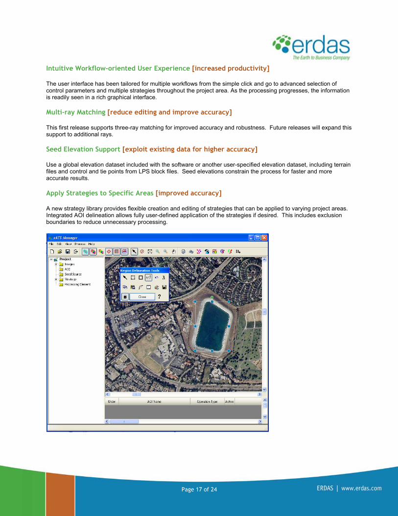
Intuitive Workflow-oriented User Experience [increased productivity]
The user interface has been tailored for multiple workflows from the simple click and go to advanced selection of control parameters and multiple strategies throughout the project area. As the processing progresses, the information is readily seen in a rich graphical interface.
Multi-ray Matching [reduce editing and improve accuracy]
This first release supports three-ray matching for improved accuracy and robustness. Future releases will expand this support to additional rays.
Seed Elevation Support [exploit existing data for higher accuracy]
Use a global elevation dataset included with the software or another user-specified elevation dataset, including terrain files and control and tie points from LPS block files. Seed elevations constrain the process for faster and more accurate results.
Apply Strategies to Specific Areas [improved accuracy]
A new strategy library provides flexible creation and editing of strategies that can be applied to varying project areas. Integrated AOI delineation allows fully user-defined application of the strategies if desired. This includes exclusion boundaries to reduce unnecessary processing.

Page 18 of 24
Automatically Remove Spikes and Blunders [decrease editing time]
Robust algorithms automatically remove spikes and blunders created during the matching process based on user-defined parameters.
Automatic Merging Operations [reduce post processing effort]
After the processing engines have finished, eATE automatically merges the results and applies the various output settings for density, classification, tiling and file formats to generate a seamless set of output products.
Graphical Status Report [easy to read and analyze]
Utilize an XML-based reporting method, which includes Google Charts and a rendered project map using OpenStreetMap.
ERDAS Extensions 2010, Version 10.1 for ArcGIS® 9.3, 9.3.1
Image Analysis™ for ArcGIS® is the solution for preparing, referencing and analyzing imagery from airborne and satellite sensors. Fully integrated with ArcGIS, it enables you to extract up-to-date information from imagery directly into a geodatabase, dramatically increasing accuracy and productivity.
With Stereo Analyst® for ArcGIS, you can create and revise a comprehensive database of feature data. Stereo visualization improves the interpretation of images, enabling more precise collection, leading to greater accuracy in resulting layers.

Page 19 of 24
An optional extension to Stereo Analyst for ArcGIS, ERDAS Terrain Editor for ArcGIS enables you to update a geodatabase terrain file. As the terrain is edited, contours are dynamically updated in the Stereo window to assist in the visualization and interpretation of the terrain. A complete set of point, breakline and area tools, including a tool for autocorrelating new points to participate in the terrain, are provided for modifying the terrain.
FeatureAssist for ArcGIS is another optional extension to Stereo Analyst for ArcGIS. It allows you to collect roof and building structures in the ESRI® multipatch format. Using templates, FeatureAssist for ArcGIS can quickly collect these features while handling varying degrees of complexity. In addition to the templates, manual construction and editing tools are provided for the creation or modification of any roof shape. To create a scene that is true to reality, roofs can be extended to the ground or to an existing terrain, creating a 3D model that can be used in a visualization package.
Together, these four extensions comprise the suite of ERDAS extensions available for ESRI’s ArcGIS desktop software. Stereo Analyst for ArcGIS
Footprint Layer to Shapefile [Automatically Generate Extents file]
A new option from the Stereo Analyst toolbar dropdown menu, the Footprint Layer to Shapefile function, creates a new polygon shapefile with the extents of the oriented images in the ArcMap document window. Each polygon within the file is automatically attributed with its corresponding image name.
Support for Single Band Display [Enhanced Display Control] Stereo Analyst now supports loading single bands from multispectral data into the Stereo Window. To accommodate various workflows, there are two ways to achieve this end result. Right-clicking on the stereo pair listing in the Stereo Tab will bring up a dialog that allows for a grayscale option. After the selection of grayscale, the band combination box allows for the choice of a single band for display. The displayed band can be changed at any time by revisiting and modifying this selection. Alternatively, selecting a single band of data in the add data dialog will result in the software constructing stereo pairs using just the single displayed band as opposed to the entire multispectral image. This option will not allow for a change of the band used for display in the Stereo Tab dialog, but will conserve system resources by limiting the amount of data loaded in ArcMap.
Additional Device Support [New USB Device options]
Support for the USB Stealth Z and SpaceExplorer devices have been added. The Stealth Z mouse is the USB replacement for the serial port Stealth Mouse. The serial port version will continue to be supported at this time. The SpaceExplorer mouse is a new device from 3Dconnection, a Logitech company.

Page 20 of 24
CSM Plug-in Manager [NTM and Tactical Platform Support]
Third party sensor model dlls built using the Community Sensor Model specification guidelines, compiled with Visual Studio 2003 or 2005 and using NITF metadata input may be added and configured to run in the Stereo Analyst environment via the new CSM Plug-in Manager. The Plug-in Manager can be accessed from the Stereo Analyst category listing in the Customization dialog and added to an existing toolbar or placed on its own toolbar. CSM models are part of the PTW/JTW, CGS targeting platforms and MSP Ruler replacement and can be obtained through the appropriate US government security channels.
New Product: Defense Formats for Stereo Analyst
The new Defense Formats for Stereo Analyst product is a US Defense Only product that adds TFRD raster and MC&G sensor model support, enabling their direct consumption and use in the Stereo Window. Defense Formats for Stereo Analyst is classified and therefore not a part of the ERDAS Extensions 2010.1 installer. Qualifying customers should contact their ERDAS sales representative for more information.
FeatureAssist for ArcGIS
Perspective Viewer [Improved support]
The perspective viewer available from the FeatureAsisst toolbar no longer requires a 3D Analyst license. The previous technology has been replaced with native code from ERDAS. This is the first in a series of enhancements planned for this tool.
ERDAS APOLLO 2010, Version 10.1
ERDAS APOLLO is an enterprise-class data management system enabling an organization to describe, catalog, search, discover and securely disseminate massive volumes of geospatial data as well as virtually any digital object in your enterprise. Available in three tiers, this interoperable OGC/ISO based solution seamlessly integrates with existing GIS environments, leveraging business systems and supporting almost any kind of data input. From low-cost, fast image delivery to a comprehensive system with the ability to dynamically edit data, perform analytics and extract information products, ERDAS APOLLO is scalable to meet your organization’s specific needs and ensures unprecedented performance even when handling the largest data archives.

Page 21 of 24
ERDAS APOLLO Essentials – Image Web Server
Improved ECW and JP2 performances [save time and hardware costs]
The new ERDAS ECW-JP2 v4.1 SDK provides enhanced support for both the ECW and JPEG2000 formats, including NPJE and EPJE profiles. Improvements include allowing faster decoding and serving through:
ECWP streaming protocol Web Map Service (WMS) interface
Extended web browser plug-in compatibility [larger user base]
The ECWP browser plug-in allows high quality imagery to be streamed over the Internet and directly into your web browser. Already compatible with both Internet Explorer and Mozilla Firefox, the plug-in is now also supported for Google Chrome browser. All of these browsers are now fully supported on Microsoft Windows 7 operating system.
Imagery rotation support for ECWP [extended user experience]
The ECWP browser plug-in now provides support for rotation of ECWP imagery streams, when enabled. This feature can be utilized within web applications, for example, to interactively adjust non-georectified data on the map.
Imagery clipping and transparency [extended user experience]
Imagery clipping and transparency is now supported during ECW file compression. With opacity channel applied, any artifacts outside of the actual image are set to transparent. This is automatically enabled in both the ECWP browser plug-in and the ER Viewer.
ERDAS APOLLO Essentials - SDI, Advantage and Professional
Microsoft SQL Server 2008 support [broader back end support]
Now users can set up WFS and WFS-T services over the Microsoft SQL Server 2008 for access to vector data and editing of spatial geometries and attributes. ERDAS APOLLO now fully supports Microsoft SQL Server 2008, Oracle 10g2, Oracle 11g and PostgreSQL 8.3 databases.
Full 64-bit architecture support [get the most from your hardware] ERDAS APOLLO now bundles a 64-bit JVM to run on Windows Server operating systems, resulting in improved stability and performance. For example, a 64-bit version of Windows allows allocating more RAM than a 32-bit system, and therefore, ERDAS APOLLO can handle larger amounts of information more effectively.

Page 22 of 24
Improved ECW and JP2 performances [save time and hardware costs]
The new ERDAS ECW-JP2 v4.1 SDK provides enhanced support for both the ECW and JPEG2000 formats, including NPJE and EPJE profiles. Improvements include allowing faster decoding and serving through:
Web Map Service (WMS) interface Web Coverage Service (WCS) interface ECWP streaming protocol (exception: not available for Essentials - SDI)
UTF8 encoding support [product globalization] Languages such as Chinese, Japanese and Arabian require support for UTF8 character encoding. ERDAS APOLLO now supports UTF8 characters in vector data and allows vector data filtering using UTF8 property values.
Improved Web Client [extended user experience]
The ERDAS APOLLO Web Client loads and runs faster, providing an extremely smooth and friendly user experience. Usability has also been improved with fully resizable panels and button tooltips.
Fixes and improvements [quality and reliability]
More than 180 bug fixes, improvements and optimizations have been implemented since the 10.0 release.
ERDAS APOLLO Advantage and Professional (only)
Download ECW and JP2 data [more efficient options]
The Clip, Zip and Ship workflow now supports ECW and JPEG2000 as output formats. These highly efficient formats dramatically reduce file size, and consequently download time. The Clip, Zip and Ship workflow enables users to discover and download any cataloged raster data, for a defined area.
Data Manager improvements [save management time]
The Data Manager has been improved to allow easier and faster data and service management:
New icons to understand imagery data configuration states Support for UNC paths in all management workflows
New Product: ERDAS APOLLO Feature Interoperability
ERDAS APOLLO Feature Interoperability provides a DGN Connector to ERDAS APOLLO, enabling direct access to MicroStation’s DGN v7 and v8 format files via WMS or WFS. This add-on module is powered by Safe Software’s FME technology and is available for ERDAS APOLLO Essentials-SDI or greater.
DGN format support [serve CAD data]
The ERDAS APOLLO Feature Interoperability enables serving DGN data stores through Web Feature Service (WFS) and Web Map Service (WMS) interfaces. This direct DGN read support includes MicroStation’s DGN v7 and v8 formats. Closely simulating its native MicroStation display, DGN symbology and text are maintained and displayed via the web services by default.

Page 23 of 24
FME vector conversion bundle [extended format support]
Safe Software’s FME Workbench and Universal Viewer are bundled and provide a rich set of tools for vector import and conversion. FME Workbench offers a graphical environment for modeling the flow of data through a process. That process may be a simple file conversion or a more involved process to change what or how attribute information or feature data is mapped through to the final product. The Universal Viewer allows for the visualization of data.
ERDAS TITAN Client 2010, Version 10.1
ERDAS TITAN Client is a freely downloadable and distributable 3D visualization client supporting a variety of OGC compliant enterprise applications, including ERDAS APOLLO. The ERDAS TITAN Viewer supports visualization of data from OGC compliant enterprise systems including ERDAS APOLLO. TITAN users can search, discover, execute and visualize data from APOLLO catalogs, directly from the 3D globe. Data can be added from local sources and a variety of OGC-compliant web services as well. In conjunction with ERDAS APOLLO Advantage, users can create sharable data and content mashups in the globe. Default basemaps are provided and users may define their own basemaps as well.
Scale dependent rendering [enhanced visualization control]
Set individual layers to display only between certain scales, based on altitude above sea level.
Dynamic tile adjustment [enhanced visualization control]
Get the optimal tile configuration based on your position in the ERDAS TITAN Viewer. A new setting automatically detects your position and requests the composition of tiles based on your perspective.
Broader language translation support [product globalization]
Language support now includes setting the default code page for character translation, keyboard typing within the application (for example, when using chat), and translation of shapefile attribute information.
Navigation enhancements [improved movement control]
Enhancements include more intuitive roaming and zooming, and continuous momentum when spinning the globe.
Terrain enhancements [stronger visualization control]
A new terrain quality slider enables higher resolution terrain or faster performance. Maximum resolution has been increased to 1 meter (previously 10 meters).
Dutch projection support [product globalization]
Added support for Dutch projection system. Upgrade to ECW SDK 4.x [faster data rendering]
For enhanced support of ECW, JPEG and ECWP.

Page 24 of 24
About ERDAS ERDAS – The Earth to Business Company – helps organizations harness the information of the changing earth for greater advantage. ERDAS creates geospatial business systems that transform our earth’s data into business information, enabling individuals, businesses and public agencies to quickly access, manage, process and share that information from anywhere. Using secure geospatial information, ERDAS solutions improve employee, customer and partner visibility to information, enabling them to respond faster and collaborate better. It also means better decision-making, increased productivity and new revenue streams. ERDAS is a part of the Hexagon Group, Sweden. For more information about ERDAS or its products and services, please call +1 770 776 3400, toll free +1 866 534 2286, or visit www.erdas.com.