ERDAS IMAGINE Installation Guide - Auburn...
273
ERDAS IMAGINE ® Installation Guide ERDAS IMAGINE V8.4 ERDAS ® , Inc. Atlanta, Georgia
Transcript of ERDAS IMAGINE Installation Guide - Auburn...

ERDAS IMAGINE ®
Installation GuideERDAS IMAGINE V8.4
ERDAS®
, Inc.Atlanta, Georgia

Copyright 1991−1999 by ERDAS ®
, Inc. All Rights Reserved.
Printed in the United States of America.
ERDAS Proprietary - Delivered under license agreement.Copying and disclosure prohibited without express written permission from ERDAS, Inc.
ERDAS Worldwide Headquarters2801 Buford Highway, NEAtlanta, Georgia 30329-2137 USAwww.erdas.comToll Free: 877/GO ERDAS (463-7327)Phone: 404/248-9000Fax: 404/248-9400User Support: 404/248-9777
ERDAS in Europe, Africa, Middle East, Asia/Pacific RimPhone: 011 44 1223 881 774Fax: 011 44 1223 880 160
All Other Worldwide InquiriesPhone: 404/248-9000Fax: 404/248-9400
Warning
All information in this document, as well as the software to which it pertains, is proprietary material of ERDAS, Inc., and is subject toan ERDAS license and non-disclosure agreement. Neither the software nor the documentation may be reproduced in any mannerwithout the prior written permission of ERDAS, Inc.
Specifications are subject to change without notice.
Trademarks
ERDAS and ERDAS IMAGINE are registered trademarks of ERDAS, Inc. CellArray, Model Maker, ERDAS Field Guide, ERDASIMAGINE Tour Guides, IMAGINE Essentials, IMAGINE Advantage, IMAGINE Professional, ERDAS MapSheets, ERDAS MapSheetsExpress, IMAGINE Radar Interpreter, IMAGINE OrthoRadar, IMAGINE StereoSAR DEM, IMAGINE IFSAR DEM, IMAGINEVirtualGIS, IMAGINE Vector, and IMAGINE Developers’ Toolkit are trademarks of ERDAS, Inc. Other brands and product names arethe property of their respective owners. ERDAS IMAGINE V8.4 1999. Part No. 29.

Table of ContentsTable of Contents . . . . . . . . . . . . . . . . . . . . . . . . . . . . . . . . . . . . . . . . . . . . . . . . . . . . . . . . . . . iii
Section OneWindows Installation and ConfigurationPreface to Windows Installation . . . . . . . . . . . . . . . . . . . . . . . . . . . . . . . . . . . . . . . . . . . . . . . . . 3
About this Manual . . . . . . . . . . . . . . . . . . . . . . . . . . . . . . . . . . . . . . . . . . . . . . . . . . . . . . . . . . . . . . . . . . . . . . . . 3
Documentation . . . . . . . . . . . . . . . . . . . . . . . . . . . . . . . . . . . . . . . . . . . . . . . . . . . . . . . . . . . . . . . . . . . . . . . . . . 3
Conventions Used in This Book . . . . . . . . . . . . . . . . . . . . . . . . . . . . . . . . . . . . . . . . . . . . . . . . . . . . . . . . . . . . . 5
CHAPTER 1Preparation for Installation under Windows
Introduction . . . . . . . . . . . . . . . . . . . . . . . . . . . . . . . . . . . . . . . . . . . . . . . . . . . . . . . . . . . . . . . . . . . . . . . . . . . . 7
System Requirements . . . . . . . . . . . . . . . . . . . . . . . . . . . . . . . . . . . . . . . . . . . . . . . . . . . . . . . . . . . . . . . . . . . . . 7
Differences Between Windows NT 4.0 and Windows 98 . . . . . . . . . . . . . . . . . . . . . . . . . . . . . . . . . . . . . . . . . . . 9
ERDAS Software Security . . . . . . . . . . . . . . . . . . . . . . . . . . . . . . . . . . . . . . . . . . . . . . . . . . . . . . . . . . . . . . . . . 10
Setting Up Your Machine for SDE . . . . . . . . . . . . . . . . . . . . . . . . . . . . . . . . . . . . . . . . . . . . . . . . . . . . . . . . . . . 10File Locations . . . . . . . . . . . . . . . . . . . . . . . . . . . . . . . . . . . . . . . . . . . . . . . . . . . . . . . . . . . . . . . . . . . . . . 10Services . . . . . . . . . . . . . . . . . . . . . . . . . . . . . . . . . . . . . . . . . . . . . . . . . . . . . . . . . . . . . . . . . . . . . . . . . . . 10Hosts . . . . . . . . . . . . . . . . . . . . . . . . . . . . . . . . . . . . . . . . . . . . . . . . . . . . . . . . . . . . . . . . . . . . . . . . . . . . . 11Yellow Pages . . . . . . . . . . . . . . . . . . . . . . . . . . . . . . . . . . . . . . . . . . . . . . . . . . . . . . . . . . . . . . . . . . . . . . . 11
Installation . . . . . . . . . . . . . . . . . . . . . . . . . . . . . . . . . . . . . . . . . . . . . . . . . . . . . . . . . . . . . . . . . . . . . . . . . . . . 11
The ERDAS IMAGINE CD-ROM . . . . . . . . . . . . . . . . . . . . . . . . . . . . . . . . . . . . . . . . . . . . . . . . . . . . . . . . . . . . . . 12
Running ERDAS IMAGINE V8.3.1 and 8.4 . . . . . . . . . . . . . . . . . . . . . . . . . . . . . . . . . . . . . . . . . . . . . . . . . . . . . 13
CHAPTER 2Server/Local Installation
Description . . . . . . . . . . . . . . . . . . . . . . . . . . . . . . . . . . . . . . . . . . . . . . . . . . . . . . . . . . . . . . . . . . . . . . . . . . . . 15
Server/Local Installation . . . . . . . . . . . . . . . . . . . . . . . . . . . . . . . . . . . . . . . . . . . . . . . . . . . . . . . . . . . . . . . . . . 15
SysID Information . . . . . . . . . . . . . . . . . . . . . . . . . . . . . . . . . . . . . . . . . . . . . . . . . . . . . . . . . . . . . . . . . . . . . . . 27
Codewords . . . . . . . . . . . . . . . . . . . . . . . . . . . . . . . . . . . . . . . . . . . . . . . . . . . . . . . . . . . . . . . . . . . . . . . . . . . . 28Codewords for Add-on Modules . . . . . . . . . . . . . . . . . . . . . . . . . . . . . . . . . . . . . . . . . . . . . . . . . . . . . . . . 29
Security Key Driver . . . . . . . . . . . . . . . . . . . . . . . . . . . . . . . . . . . . . . . . . . . . . . . . . . . . . . . . . . . . . . . . . . . . . 30
Security Error Messages . . . . . . . . . . . . . . . . . . . . . . . . . . . . . . . . . . . . . . . . . . . . . . . . . . . . . . . . . . . . . . . . . 31
CHAPTER 3Client Installation
Description . . . . . . . . . . . . . . . . . . . . . . . . . . . . . . . . . . . . . . . . . . . . . . . . . . . . . . . . . . . . . . . . . . . . . . . . . . . . 33
iiiInstallation Guide

Table of Contents
Client Installation . . . . . . . . . . . . . . . . . . . . . . . . . . . . . . . . . . . . . . . . . . . . . . . . . . . . . . . . . . . . . . . . . . . . . . . 33
Security Error Messages. . . . . . . . . . . . . . . . . . . . . . . . . . . . . . . . . . . . . . . . . . . . . . . . . . . . . . . . . . . . . . . . . . 41
CHAPTER 4Erdmaster
Description . . . . . . . . . . . . . . . . . . . . . . . . . . . . . . . . . . . . . . . . . . . . . . . . . . . . . . . . . . . . . . . . . . . . . . . . . . . . 43
ERDAS Software Security . . . . . . . . . . . . . . . . . . . . . . . . . . . . . . . . . . . . . . . . . . . . . . . . . . . . . . . . . . . . . . . . . 43
Installation . . . . . . . . . . . . . . . . . . . . . . . . . . . . . . . . . . . . . . . . . . . . . . . . . . . . . . . . . . . . . . . . . . . . . . . . . . . . 43Start TCP/IP Services . . . . . . . . . . . . . . . . . . . . . . . . . . . . . . . . . . . . . . . . . . . . . . . . . . . . . . . . . . . . . . . . 44Start the License Broker . . . . . . . . . . . . . . . . . . . . . . . . . . . . . . . . . . . . . . . . . . . . . . . . . . . . . . . . . . . . . . 44Autostart the License Broker . . . . . . . . . . . . . . . . . . . . . . . . . . . . . . . . . . . . . . . . . . . . . . . . . . . . . . . . . . . 44Stop the License Broker . . . . . . . . . . . . . . . . . . . . . . . . . . . . . . . . . . . . . . . . . . . . . . . . . . . . . . . . . . . . . . 45Remove the License Broker . . . . . . . . . . . . . . . . . . . . . . . . . . . . . . . . . . . . . . . . . . . . . . . . . . . . . . . . . . . 45
Using V8.4 Security with Previous Versions of ERDAS IMAGINE Software . . . . . . . . . . . . . . . . . . . . . . . . . . . . 45
CHAPTER 5Configure Tablet Digitizer
Description . . . . . . . . . . . . . . . . . . . . . . . . . . . . . . . . . . . . . . . . . . . . . . . . . . . . . . . . . . . . . . . . . . . . . . . . . . . . 47
Select a Serial Line . . . . . . . . . . . . . . . . . . . . . . . . . . . . . . . . . . . . . . . . . . . . . . . . . . . . . . . . . . . . . . . . . . . . . . 47
Connect Tablet Digitizer . . . . . . . . . . . . . . . . . . . . . . . . . . . . . . . . . . . . . . . . . . . . . . . . . . . . . . . . . . . . . . . . . . 47
Switch Settings and Formats . . . . . . . . . . . . . . . . . . . . . . . . . . . . . . . . . . . . . . . . . . . . . . . . . . . . . . . . . . . . . . 48Altek Series Model AC32 Moveable Menu . . . . . . . . . . . . . . . . . . . . . . . . . . . . . . . . . . . . . . . . . . . . . . . . 48Altek Series Model 33240 Tablet . . . . . . . . . . . . . . . . . . . . . . . . . . . . . . . . . . . . . . . . . . . . . . . . . . . . . . . 48CalComp 9100 Series . . . . . . . . . . . . . . . . . . . . . . . . . . . . . . . . . . . . . . . . . . . . . . . . . . . . . . . . . . . . . . . . 49CalComp 9500 Series . . . . . . . . . . . . . . . . . . . . . . . . . . . . . . . . . . . . . . . . . . . . . . . . . . . . . . . . . . . . . . . . 50CalComp Drawing Board II and III . . . . . . . . . . . . . . . . . . . . . . . . . . . . . . . . . . . . . . . . . . . . . . . . . . . . . . 51GTCO Accutab Series Custom Configuration Menu . . . . . . . . . . . . . . . . . . . . . . . . . . . . . . . . . . . . . . . . . 52GTCO DIGI-PAD Series . . . . . . . . . . . . . . . . . . . . . . . . . . . . . . . . . . . . . . . . . . . . . . . . . . . . . . . . . . . . . . 52
Connect to HyperTerminal . . . . . . . . . . . . . . . . . . . . . . . . . . . . . . . . . . . . . . . . . . . . . . . . . . . . . . . . . . . . . . . . 53
Configuring the Tablet Digitizer . . . . . . . . . . . . . . . . . . . . . . . . . . . . . . . . . . . . . . . . . . . . . . . . . . . . . . . . . . . . 55
CHAPTER 6Configure Tape Drive
Description . . . . . . . . . . . . . . . . . . . . . . . . . . . . . . . . . . . . . . . . . . . . . . . . . . . . . . . . . . . . . . . . . . . . . . . . . . . . 57
Local Tape Drive (Windows NT only) . . . . . . . . . . . . . . . . . . . . . . . . . . . . . . . . . . . . . . . . . . . . . . . . . . . . . . . . 57
Configuring a Remote Tape Drive . . . . . . . . . . . . . . . . . . . . . . . . . . . . . . . . . . . . . . . . . . . . . . . . . . . . . . . . . . 59
Configuring a Remote Tape Drive on a UNIX Machine . . . . . . . . . . . . . . . . . . . . . . . . . . . . . . . . . . . . . . . . . . . 62Automatic Tape Server Start-up at Time of System Boot . . . . . . . . . . . . . . . . . . . . . . . . . . . . . . . . . . . . . 62Set Up Tape Drive . . . . . . . . . . . . . . . . . . . . . . . . . . . . . . . . . . . . . . . . . . . . . . . . . . . . . . . . . . . . . . . . . . 62
CHAPTER 7Adding Fonts to Annotation
Introduction . . . . . . . . . . . . . . . . . . . . . . . . . . . . . . . . . . . . . . . . . . . . . . . . . . . . . . . . . . . . . . . . . . . . . . . . . . . 63
Create an .fdb File . . . . . . . . . . . . . . . . . . . . . . . . . . . . . . . . . . . . . . . . . . . . . . . . . . . . . . . . . . . . . . . . . . . . . . 63
Example .fdb Entries. . . . . . . . . . . . . . . . . . . . . . . . . . . . . . . . . . . . . . . . . . . . . . . . . . . . . . . . . . . . . . . . . . . . . 65
iv ERDAS IMAGINE
CHAPTER 8Windows Printing
Introduction . . . . . . . . . . . . . . . . . . . . . . . . . . . . . . . . . . . . . . . . . . . . . . . . . . . . . . . . . . . . . . . . . . . . . . . . . . . 67
Troubleshooting . . . . . . . . . . . . . . . . . . . . . . . . . . . . . . . . . . . . . . . . . . . . . . . . . . . . . . . . . . . . . . . . . . . . . . . . 68Out of Memory/Data Lost . . . . . . . . . . . . . . . . . . . . . . . . . . . . . . . . . . . . . . . . . . . . . . . . . . . . . . . . . . . . . 68Nothing Prints . . . . . . . . . . . . . . . . . . . . . . . . . . . . . . . . . . . . . . . . . . . . . . . . . . . . . . . . . . . . . . . . . . . . . . 68Preferences . . . . . . . . . . . . . . . . . . . . . . . . . . . . . . . . . . . . . . . . . . . . . . . . . . . . . . . . . . . . . . . . . . . . . . . . 69Spool RAW Data . . . . . . . . . . . . . . . . . . . . . . . . . . . . . . . . . . . . . . . . . . . . . . . . . . . . . . . . . . . . . . . . . . . . 69Changing the Location of the Spool Folder . . . . . . . . . . . . . . . . . . . . . . . . . . . . . . . . . . . . . . . . . . . . . . . . 71
Scenarios . . . . . . . . . . . . . . . . . . . . . . . . . . . . . . . . . . . . . . . . . . . . . . . . . . . . . . . . . . . . . . . . . . . . . . . . . . . . . 72No Pre-Rasterize . . . . . . . . . . . . . . . . . . . . . . . . . . . . . . . . . . . . . . . . . . . . . . . . . . . . . . . . . . . . . . . . . . . . 72Pre-Rasterize . . . . . . . . . . . . . . . . . . . . . . . . . . . . . . . . . . . . . . . . . . . . . . . . . . . . . . . . . . . . . . . . . . . . . . 87
CHAPTER 9Configuring IMAGINE VirtualGIS for Windows
Stereo Configuration for Windows Systems . . . . . . . . . . . . . . . . . . . . . . . . . . . . . . . . . . . . . . . . . . . . . . . . . . . 95
ERDAS IMAGINE Preference Settings . . . . . . . . . . . . . . . . . . . . . . . . . . . . . . . . . . . . . . . . . . . . . . . . . . . . . . . . 95
Section TwoUNIX Installation and ConfigurationPreface to UNIX Installation . . . . . . . . . . . . . . . . . . . . . . . . . . . . . . . . . . . . . . . . . . . . . . . . . . . 99
About This Manual . . . . . . . . . . . . . . . . . . . . . . . . . . . . . . . . . . . . . . . . . . . . . . . . . . . . . . . . . . . . . . . . . . . . . . 99
Documentation . . . . . . . . . . . . . . . . . . . . . . . . . . . . . . . . . . . . . . . . . . . . . . . . . . . . . . . . . . . . . . . . . . . . . . . . 100
Conventions Used in This Book . . . . . . . . . . . . . . . . . . . . . . . . . . . . . . . . . . . . . . . . . . . . . . . . . . . . . . . . . . . 102
Obsolete . . . . . . . . . . . . . . . . . . . . . . . . . . . . . . . . . . . . . . . . . . . . . . . . . . . . . . . . . . . . . . . . . . . . . . . . . . . . . 103
CHAPTER 10Preparation for Installation under UNIX
Description . . . . . . . . . . . . . . . . . . . . . . . . . . . . . . . . . . . . . . . . . . . . . . . . . . . . . . . . . . . . . . . . . . . . . . . . . . . 105
Requirements . . . . . . . . . . . . . . . . . . . . . . . . . . . . . . . . . . . . . . . . . . . . . . . . . . . . . . . . . . . . . . . . . . . . . . . . . 106Hardware . . . . . . . . . . . . . . . . . . . . . . . . . . . . . . . . . . . . . . . . . . . . . . . . . . . . . . . . . . . . . . . . . . . . . . . . . 107Swap Space . . . . . . . . . . . . . . . . . . . . . . . . . . . . . . . . . . . . . . . . . . . . . . . . . . . . . . . . . . . . . . . . . . . . . . 108
User Accounts . . . . . . . . . . . . . . . . . . . . . . . . . . . . . . . . . . . . . . . . . . . . . . . . . . . . . . . . . . . . . . . . . . . . . . . . . 109
Setting Up Your Window Environment . . . . . . . . . . . . . . . . . . . . . . . . . . . . . . . . . . . . . . . . . . . . . . . . . . . . . . 110OpenLook Window Manager (olwm) . . . . . . . . . . . . . . . . . . . . . . . . . . . . . . . . . . . . . . . . . . . . . . . . . . . . 110Motif Window Manager (mwm) . . . . . . . . . . . . . . . . . . . . . . . . . . . . . . . . . . . . . . . . . . . . . . . . . . . . . . . . 110
ERDAS Software Security . . . . . . . . . . . . . . . . . . . . . . . . . . . . . . . . . . . . . . . . . . . . . . . . . . . . . . . . . . . . . . . . 114
Installation Instructions . . . . . . . . . . . . . . . . . . . . . . . . . . . . . . . . . . . . . . . . . . . . . . . . . . . . . . . . . . . . . . . . . 114Standard Installation . . . . . . . . . . . . . . . . . . . . . . . . . . . . . . . . . . . . . . . . . . . . . . . . . . . . . . . . . . . . . . . . 115Advanced Installation . . . . . . . . . . . . . . . . . . . . . . . . . . . . . . . . . . . . . . . . . . . . . . . . . . . . . . . . . . . . . . . 115
Security Codewords . . . . . . . . . . . . . . . . . . . . . . . . . . . . . . . . . . . . . . . . . . . . . . . . . . . . . . . . . . . . . . . . . . . . 116
vInstallation Guide

Table of Contents
Generate System ID . . . . . . . . . . . . . . . . . . . . . . . . . . . . . . . . . . . . . . . . . . . . . . . . . . . . . . . . . . . . . . . . . . . . 117Showsysid Instructions . . . . . . . . . . . . . . . . . . . . . . . . . . . . . . . . . . . . . . . . . . . . . . . . . . . . . . . . . . . . . . 118Non-showsysid Instructions . . . . . . . . . . . . . . . . . . . . . . . . . . . . . . . . . . . . . . . . . . . . . . . . . . . . . . . . . . 118
CHAPTER 11Standard CD-ROM Installation
Standard vs. Advanced Installation . . . . . . . . . . . . . . . . . . . . . . . . . . . . . . . . . . . . . . . . . . . . . . . . . . . . . . . . 121System Architecture . . . . . . . . . . . . . . . . . . . . . . . . . . . . . . . . . . . . . . . . . . . . . . . . . . . . . . . . . . . . . . . . 122
Setup for Installation . . . . . . . . . . . . . . . . . . . . . . . . . . . . . . . . . . . . . . . . . . . . . . . . . . . . . . . . . . . . . . . . . . . 122
Mount the CD-ROM . . . . . . . . . . . . . . . . . . . . . . . . . . . . . . . . . . . . . . . . . . . . . . . . . . . . . . . . . . . . . . . . . . . . . 122Compaq AlphaStation . . . . . . . . . . . . . . . . . . . . . . . . . . . . . . . . . . . . . . . . . . . . . . . . . . . . . . . . . . . . . . . 122HP 9000 . . . . . . . . . . . . . . . . . . . . . . . . . . . . . . . . . . . . . . . . . . . . . . . . . . . . . . . . . . . . . . . . . . . . . . . . . 123IBM RS/6000 . . . . . . . . . . . . . . . . . . . . . . . . . . . . . . . . . . . . . . . . . . . . . . . . . . . . . . . . . . . . . . . . . . . . . 123Silicon Graphics . . . . . . . . . . . . . . . . . . . . . . . . . . . . . . . . . . . . . . . . . . . . . . . . . . . . . . . . . . . . . . . . . . . 123Sun SPARCstation . . . . . . . . . . . . . . . . . . . . . . . . . . . . . . . . . . . . . . . . . . . . . . . . . . . . . . . . . . . . . . . . . 125
Run Install Program . . . . . . . . . . . . . . . . . . . . . . . . . . . . . . . . . . . . . . . . . . . . . . . . . . . . . . . . . . . . . . . . . . . . 126Selecting Modules . . . . . . . . . . . . . . . . . . . . . . . . . . . . . . . . . . . . . . . . . . . . . . . . . . . . . . . . . . . . . . . . . . 127Security Configuration . . . . . . . . . . . . . . . . . . . . . . . . . . . . . . . . . . . . . . . . . . . . . . . . . . . . . . . . . . . . . . . 131Security Codewords . . . . . . . . . . . . . . . . . . . . . . . . . . . . . . . . . . . . . . . . . . . . . . . . . . . . . . . . . . . . . . . . 132Convert International Fonts . . . . . . . . . . . . . . . . . . . . . . . . . . . . . . . . . . . . . . . . . . . . . . . . . . . . . . . . . . . 134Automatic CD-ROM Mounting . . . . . . . . . . . . . . . . . . . . . . . . . . . . . . . . . . . . . . . . . . . . . . . . . . . . . . . . 134Setting Up Your System . . . . . . . . . . . . . . . . . . . . . . . . . . . . . . . . . . . . . . . . . . . . . . . . . . . . . . . . . . . . . 136
Running ERDAS IMAGINE V8.3 and 8.4 . . . . . . . . . . . . . . . . . . . . . . . . . . . . . . . . . . . . . . . . . . . . . . . . . . . . . . 138
Starting ERDAS IMAGINE . . . . . . . . . . . . . . . . . . . . . . . . . . . . . . . . . . . . . . . . . . . . . . . . . . . . . . . . . . . . . . . . 140
Using IMAGINE On-Line Documentation . . . . . . . . . . . . . . . . . . . . . . . . . . . . . . . . . . . . . . . . . . . . . . . . . . . . . 140
Adding Another System . . . . . . . . . . . . . . . . . . . . . . . . . . . . . . . . . . . . . . . . . . . . . . . . . . . . . . . . . . . . . . . . . 140
Adding More Modules . . . . . . . . . . . . . . . . . . . . . . . . . . . . . . . . . . . . . . . . . . . . . . . . . . . . . . . . . . . . . . . . . . . 142Module was Selected . . . . . . . . . . . . . . . . . . . . . . . . . . . . . . . . . . . . . . . . . . . . . . . . . . . . . . . . . . . . . . . 142
Error Messages . . . . . . . . . . . . . . . . . . . . . . . . . . . . . . . . . . . . . . . . . . . . . . . . . . . . . . . . . . . . . . . . . . . . . . . . 143
CHAPTER 12Advanced CD-ROM Installation
Advanced vs. Standard Installation . . . . . . . . . . . . . . . . . . . . . . . . . . . . . . . . . . . . . . . . . . . . . . . . . . . . . . . . 145System Architecture . . . . . . . . . . . . . . . . . . . . . . . . . . . . . . . . . . . . . . . . . . . . . . . . . . . . . . . . . . . . . . . . 146Log in to Root or Non-root Account . . . . . . . . . . . . . . . . . . . . . . . . . . . . . . . . . . . . . . . . . . . . . . . . . . . . 146All Other Workstations . . . . . . . . . . . . . . . . . . . . . . . . . . . . . . . . . . . . . . . . . . . . . . . . . . . . . . . . . . . . . . 147
Access Install Program from a Local CD-ROM Drive. . . . . . . . . . . . . . . . . . . . . . . . . . . . . . . . . . . . . . . . . . . . 147Compaq AlphaStation . . . . . . . . . . . . . . . . . . . . . . . . . . . . . . . . . . . . . . . . . . . . . . . . . . . . . . . . . . . . . . . 147HP 9000 . . . . . . . . . . . . . . . . . . . . . . . . . . . . . . . . . . . . . . . . . . . . . . . . . . . . . . . . . . . . . . . . . . . . . . . . . 147IBM RS/6000 . . . . . . . . . . . . . . . . . . . . . . . . . . . . . . . . . . . . . . . . . . . . . . . . . . . . . . . . . . . . . . . . . . . . . 148Silicon Graphics . . . . . . . . . . . . . . . . . . . . . . . . . . . . . . . . . . . . . . . . . . . . . . . . . . . . . . . . . . . . . . . . . . . 148Sun SPARCstation . . . . . . . . . . . . . . . . . . . . . . . . . . . . . . . . . . . . . . . . . . . . . . . . . . . . . . . . . . . . . . . . . 148Compaq AlphaStation . . . . . . . . . . . . . . . . . . . . . . . . . . . . . . . . . . . . . . . . . . . . . . . . . . . . . . . . . . . . . . . 149HP 9000 . . . . . . . . . . . . . . . . . . . . . . . . . . . . . . . . . . . . . . . . . . . . . . . . . . . . . . . . . . . . . . . . . . . . . . . . . 149IBM RS/6000 . . . . . . . . . . . . . . . . . . . . . . . . . . . . . . . . . . . . . . . . . . . . . . . . . . . . . . . . . . . . . . . . . . . . . 149Silicon Graphics . . . . . . . . . . . . . . . . . . . . . . . . . . . . . . . . . . . . . . . . . . . . . . . . . . . . . . . . . . . . . . . . . . . 149Sun SPARCstation . . . . . . . . . . . . . . . . . . . . . . . . . . . . . . . . . . . . . . . . . . . . . . . . . . . . . . . . . . . . . . . . . 149
vi ERDAS IMAGINE

Access Install Program from a Remote CD-ROM Drive . . . . . . . . . . . . . . . . . . . . . . . . . . . . . . . . . . . . . . . . . . 149Compaq AlphaStation . . . . . . . . . . . . . . . . . . . . . . . . . . . . . . . . . . . . . . . . . . . . . . . . . . . . . . . . . . . . . . . 150HP 9000 . . . . . . . . . . . . . . . . . . . . . . . . . . . . . . . . . . . . . . . . . . . . . . . . . . . . . . . . . . . . . . . . . . . . . . . . . 150IBM RS/6000 . . . . . . . . . . . . . . . . . . . . . . . . . . . . . . . . . . . . . . . . . . . . . . . . . . . . . . . . . . . . . . . . . . . . . . 150Silicon Graphics . . . . . . . . . . . . . . . . . . . . . . . . . . . . . . . . . . . . . . . . . . . . . . . . . . . . . . . . . . . . . . . . . . . 150Sun SPARCstation . . . . . . . . . . . . . . . . . . . . . . . . . . . . . . . . . . . . . . . . . . . . . . . . . . . . . . . . . . . . . . . . . 151Compaq AlphaStation . . . . . . . . . . . . . . . . . . . . . . . . . . . . . . . . . . . . . . . . . . . . . . . . . . . . . . . . . . . . . . . 151HP 9000 . . . . . . . . . . . . . . . . . . . . . . . . . . . . . . . . . . . . . . . . . . . . . . . . . . . . . . . . . . . . . . . . . . . . . . . . . 151IBM RS/6000 . . . . . . . . . . . . . . . . . . . . . . . . . . . . . . . . . . . . . . . . . . . . . . . . . . . . . . . . . . . . . . . . . . . . . . 151Silicon Graphics . . . . . . . . . . . . . . . . . . . . . . . . . . . . . . . . . . . . . . . . . . . . . . . . . . . . . . . . . . . . . . . . . . . 151Sun SPARCstation . . . . . . . . . . . . . . . . . . . . . . . . . . . . . . . . . . . . . . . . . . . . . . . . . . . . . . . . . . . . . . . . . 151Silicon Graphics with mediad . . . . . . . . . . . . . . . . . . . . . . . . . . . . . . . . . . . . . . . . . . . . . . . . . . . . . . . . . 152Sun SPARCstation Solaris 2.6 or 2.7 with vold . . . . . . . . . . . . . . . . . . . . . . . . . . . . . . . . . . . . . . . . . . . . 152
Run Install Program . . . . . . . . . . . . . . . . . . . . . . . . . . . . . . . . . . . . . . . . . . . . . . . . . . . . . . . . . . . . . . . . . . . . 153Selecting Modules . . . . . . . . . . . . . . . . . . . . . . . . . . . . . . . . . . . . . . . . . . . . . . . . . . . . . . . . . . . . . . . . . . 154Security Configuration . . . . . . . . . . . . . . . . . . . . . . . . . . . . . . . . . . . . . . . . . . . . . . . . . . . . . . . . . . . . . . . 158Security Codewords . . . . . . . . . . . . . . . . . . . . . . . . . . . . . . . . . . . . . . . . . . . . . . . . . . . . . . . . . . . . . . . . 162Convert International Fonts . . . . . . . . . . . . . . . . . . . . . . . . . . . . . . . . . . . . . . . . . . . . . . . . . . . . . . . . . . . 164Automatic CD-ROM Mounting . . . . . . . . . . . . . . . . . . . . . . . . . . . . . . . . . . . . . . . . . . . . . . . . . . . . . . . . . 164Setting Up Your System . . . . . . . . . . . . . . . . . . . . . . . . . . . . . . . . . . . . . . . . . . . . . . . . . . . . . . . . . . . . . 166
Running ERDAS IMAGINE V8.3 and 8.4 . . . . . . . . . . . . . . . . . . . . . . . . . . . . . . . . . . . . . . . . . . . . . . . . . . . . . . 168
Starting ERDAS IMAGINE . . . . . . . . . . . . . . . . . . . . . . . . . . . . . . . . . . . . . . . . . . . . . . . . . . . . . . . . . . . . . . . . 168
Using IMAGINE On-Line Documentation . . . . . . . . . . . . . . . . . . . . . . . . . . . . . . . . . . . . . . . . . . . . . . . . . . . . . 169
Adding Another System . . . . . . . . . . . . . . . . . . . . . . . . . . . . . . . . . . . . . . . . . . . . . . . . . . . . . . . . . . . . . . . . . 169
Adding More Modules . . . . . . . . . . . . . . . . . . . . . . . . . . . . . . . . . . . . . . . . . . . . . . . . . . . . . . . . . . . . . . . . . . . 171Module was Selected . . . . . . . . . . . . . . . . . . . . . . . . . . . . . . . . . . . . . . . . . . . . . . . . . . . . . . . . . . . . . . . 171Module was Not Selected . . . . . . . . . . . . . . . . . . . . . . . . . . . . . . . . . . . . . . . . . . . . . . . . . . . . . . . . . . . . 171
Error Messages . . . . . . . . . . . . . . . . . . . . . . . . . . . . . . . . . . . . . . . . . . . . . . . . . . . . . . . . . . . . . . . . . . . . . . . . 172
CHAPTER 13Security System
Introduction . . . . . . . . . . . . . . . . . . . . . . . . . . . . . . . . . . . . . . . . . . . . . . . . . . . . . . . . . . . . . . . . . . . . . . . . . . 173
Using erdmaster . . . . . . . . . . . . . . . . . . . . . . . . . . . . . . . . . . . . . . . . . . . . . . . . . . . . . . . . . . . . . . . . . . . . . . . 174
Error Messages . . . . . . . . . . . . . . . . . . . . . . . . . . . . . . . . . . . . . . . . . . . . . . . . . . . . . . . . . . . . . . . . . . . . . . . 176
Using V8.4 Security with Previous Versions of ERDAS Software . . . . . . . . . . . . . . . . . . . . . . . . . . . . . . . . . . 178
CHAPTER 14FontTastic Font Manager
Introduction . . . . . . . . . . . . . . . . . . . . . . . . . . . . . . . . . . . . . . . . . . . . . . . . . . . . . . . . . . . . . . . . . . . . . . . . . . 181Start FontTastic Font Manager . . . . . . . . . . . . . . . . . . . . . . . . . . . . . . . . . . . . . . . . . . . . . . . . . . . . . . . . 181
Install Fonts . . . . . . . . . . . . . . . . . . . . . . . . . . . . . . . . . . . . . . . . . . . . . . . . . . . . . . . . . . . . . . . . . . . . . . . . . . 182Select Files to Add . . . . . . . . . . . . . . . . . . . . . . . . . . . . . . . . . . . . . . . . . . . . . . . . . . . . . . . . . . . . . . . . . 183Update Services . . . . . . . . . . . . . . . . . . . . . . . . . . . . . . . . . . . . . . . . . . . . . . . . . . . . . . . . . . . . . . . . . . . 183
Update Font Usage . . . . . . . . . . . . . . . . . . . . . . . . . . . . . . . . . . . . . . . . . . . . . . . . . . . . . . . . . . . . . . . . . . . . . 184Create an .fdb File . . . . . . . . . . . . . . . . . . . . . . . . . . . . . . . . . . . . . . . . . . . . . . . . . . . . . . . . . . . . . . . . . . 184
Running the Gallium FontTastic Font Server . . . . . . . . . . . . . . . . . . . . . . . . . . . . . . . . . . . . . . . . . . . . . . . . . 187
viiInstallation Guide

Table of Contents
CHAPTER 15Printer Connections
Description . . . . . . . . . . . . . . . . . . . . . . . . . . . . . . . . . . . . . . . . . . . . . . . . . . . . . . . . . . . . . . . . . . . . . . . . . . . 189System Queue . . . . . . . . . . . . . . . . . . . . . . . . . . . . . . . . . . . . . . . . . . . . . . . . . . . . . . . . . . . . . . . . . . . . 189JetDirect . . . . . . . . . . . . . . . . . . . . . . . . . . . . . . . . . . . . . . . . . . . . . . . . . . . . . . . . . . . . . . . . . . . . . . . . . 190TFTP . . . . . . . . . . . . . . . . . . . . . . . . . . . . . . . . . . . . . . . . . . . . . . . . . . . . . . . . . . . . . . . . . . . . . . . . . . . . 190File . . . . . . . . . . . . . . . . . . . . . . . . . . . . . . . . . . . . . . . . . . . . . . . . . . . . . . . . . . . . . . . . . . . . . . . . . . . . . 190Drop Directory . . . . . . . . . . . . . . . . . . . . . . . . . . . . . . . . . . . . . . . . . . . . . . . . . . . . . . . . . . . . . . . . . . . . . 191Other Command . . . . . . . . . . . . . . . . . . . . . . . . . . . . . . . . . . . . . . . . . . . . . . . . . . . . . . . . . . . . . . . . . . . 191
CHAPTER 16HPRTL Plotters
Description . . . . . . . . . . . . . . . . . . . . . . . . . . . . . . . . . . . . . . . . . . . . . . . . . . . . . . . . . . . . . . . . . . . . . . . . . . . 193
IMAGINE Configuration Editor . . . . . . . . . . . . . . . . . . . . . . . . . . . . . . . . . . . . . . . . . . . . . . . . . . . . . . . . . . . . 194Set Up Preferences . . . . . . . . . . . . . . . . . . . . . . . . . . . . . . . . . . . . . . . . . . . . . . . . . . . . . . . . . . . . . . . . 195Set Up Print Queue . . . . . . . . . . . . . . . . . . . . . . . . . . . . . . . . . . . . . . . . . . . . . . . . . . . . . . . . . . . . . . . . . 197
Remote Printer Access . . . . . . . . . . . . . . . . . . . . . . . . . . . . . . . . . . . . . . . . . . . . . . . . . . . . . . . . . . . . . . . . . . 197Remote vs. Local . . . . . . . . . . . . . . . . . . . . . . . . . . . . . . . . . . . . . . . . . . . . . . . . . . . . . . . . . . . . . . . . . . 197Set Up Print Queue . . . . . . . . . . . . . . . . . . . . . . . . . . . . . . . . . . . . . . . . . . . . . . . . . . . . . . . . . . . . . . . . . 198
CHAPTER 17PostScript Printers
Description . . . . . . . . . . . . . . . . . . . . . . . . . . . . . . . . . . . . . . . . . . . . . . . . . . . . . . . . . . . . . . . . . . . . . . . . . . . 199
Parallel Setup(IBM RS/6000 Workstations Only) . . . . . . . . . . . . . . . . . . . . . . . . . . . . . . . . . . . . . . . . . . . . . . . . . . . . . . . . . 200
Installation for Network Interface . . . . . . . . . . . . . . . . . . . . . . . . . . . . . . . . . . . . . . . . . . . . . . . . . . . . . . . . . . 200Hardware . . . . . . . . . . . . . . . . . . . . . . . . . . . . . . . . . . . . . . . . . . . . . . . . . . . . . . . . . . . . . . . . . . . . . . . . 200Set Up Network Connections . . . . . . . . . . . . . . . . . . . . . . . . . . . . . . . . . . . . . . . . . . . . . . . . . . . . . . . . . 201
IMAGINE Configuration Editor . . . . . . . . . . . . . . . . . . . . . . . . . . . . . . . . . . . . . . . . . . . . . . . . . . . . . . . . . . . . 201Set Up Preferences . . . . . . . . . . . . . . . . . . . . . . . . . . . . . . . . . . . . . . . . . . . . . . . . . . . . . . . . . . . . . . . . 202Set Up Print Queue . . . . . . . . . . . . . . . . . . . . . . . . . . . . . . . . . . . . . . . . . . . . . . . . . . . . . . . . . . . . . . . . . 204
Remote Printer Access . . . . . . . . . . . . . . . . . . . . . . . . . . . . . . . . . . . . . . . . . . . . . . . . . . . . . . . . . . . . . . . . . . 204Remote vs. Local . . . . . . . . . . . . . . . . . . . . . . . . . . . . . . . . . . . . . . . . . . . . . . . . . . . . . . . . . . . . . . . . . . 204Set Up Print Queue . . . . . . . . . . . . . . . . . . . . . . . . . . . . . . . . . . . . . . . . . . . . . . . . . . . . . . . . . . . . . . . . . 205
CHAPTER 18Printer Setup for On-Line Help
Description . . . . . . . . . . . . . . . . . . . . . . . . . . . . . . . . . . . . . . . . . . . . . . . . . . . . . . . . . . . . . . . . . . . . . . . . . . . 207
Printer Setup. . . . . . . . . . . . . . . . . . . . . . . . . . . . . . . . . . . . . . . . . . . . . . . . . . . . . . . . . . . . . . . . . . . . . . . . . . 207
CHAPTER 19Host System
Description . . . . . . . . . . . . . . . . . . . . . . . . . . . . . . . . . . . . . . . . . . . . . . . . . . . . . . . . . . . . . . . . . . . . . . . . . . . 211
IMAGINE Configuration Editor . . . . . . . . . . . . . . . . . . . . . . . . . . . . . . . . . . . . . . . . . . . . . . . . . . . . . . . . . . . . 211Set Up Preferences . . . . . . . . . . . . . . . . . . . . . . . . . . . . . . . . . . . . . . . . . . . . . . . . . . . . . . . . . . . . . . . . 212
viii ERDAS IMAGINE
CHAPTER 20CD-ROM Device
Description . . . . . . . . . . . . . . . . . . . . . . . . . . . . . . . . . . . . . . . . . . . . . . . . . . . . . . . . . . . . . . . . . . . . . . . . . . . 213
IMAGINE Configuration Editor . . . . . . . . . . . . . . . . . . . . . . . . . . . . . . . . . . . . . . . . . . . . . . . . . . . . . . . . . . . . . 213Set Up Preferences . . . . . . . . . . . . . . . . . . . . . . . . . . . . . . . . . . . . . . . . . . . . . . . . . . . . . . . . . . . . . . . . . 214
Enable Automatic Mounting of CD-ROM Device . . . . . . . . . . . . . . . . . . . . . . . . . . . . . . . . . . . . . . . . . . . . . . . 216cdromctl Program . . . . . . . . . . . . . . . . . . . . . . . . . . . . . . . . . . . . . . . . . . . . . . . . . . . . . . . . . . . . . . . . . . 217
Manual Mounting of CD-ROM Device . . . . . . . . . . . . . . . . . . . . . . . . . . . . . . . . . . . . . . . . . . . . . . . . . . . . . . . . 218
Remote CD-ROM Access . . . . . . . . . . . . . . . . . . . . . . . . . . . . . . . . . . . . . . . . . . . . . . . . . . . . . . . . . . . . . . . . . 219Log In as Root . . . . . . . . . . . . . . . . . . . . . . . . . . . . . . . . . . . . . . . . . . . . . . . . . . . . . . . . . . . . . . . . . . . . . 220Mount the CD-ROM . . . . . . . . . . . . . . . . . . . . . . . . . . . . . . . . . . . . . . . . . . . . . . . . . . . . . . . . . . . . . . . . . 220Export to Network . . . . . . . . . . . . . . . . . . . . . . . . . . . . . . . . . . . . . . . . . . . . . . . . . . . . . . . . . . . . . . . . . . 221Unmount the CD-ROM (HP 9000 only) . . . . . . . . . . . . . . . . . . . . . . . . . . . . . . . . . . . . . . . . . . . . . . . . . . 222
CHAPTER 21Tape Drive
Description . . . . . . . . . . . . . . . . . . . . . . . . . . . . . . . . . . . . . . . . . . . . . . . . . . . . . . . . . . . . . . . . . . . . . . . . . . . 223
IMAGINE Configuration Editor . . . . . . . . . . . . . . . . . . . . . . . . . . . . . . . . . . . . . . . . . . . . . . . . . . . . . . . . . . . . . 223Set Up Preferences . . . . . . . . . . . . . . . . . . . . . . . . . . . . . . . . . . . . . . . . . . . . . . . . . . . . . . . . . . . . . . . . . 224
Remote Tape Access . . . . . . . . . . . . . . . . . . . . . . . . . . . . . . . . . . . . . . . . . . . . . . . . . . . . . . . . . . . . . . . . . . . 226Set Up Tape Drive . . . . . . . . . . . . . . . . . . . . . . . . . . . . . . . . . . . . . . . . . . . . . . . . . . . . . . . . . . . . . . . . . . 227
CHAPTER 22Tablet Digitizers
Description . . . . . . . . . . . . . . . . . . . . . . . . . . . . . . . . . . . . . . . . . . . . . . . . . . . . . . . . . . . . . . . . . . . . . . . . . . . 229
Select a Serial Line . . . . . . . . . . . . . . . . . . . . . . . . . . . . . . . . . . . . . . . . . . . . . . . . . . . . . . . . . . . . . . . . . . . . . 229
Disable Login Line . . . . . . . . . . . . . . . . . . . . . . . . . . . . . . . . . . . . . . . . . . . . . . . . . . . . . . . . . . . . . . . . . . . . . 230
Connect Digitizer . . . . . . . . . . . . . . . . . . . . . . . . . . . . . . . . . . . . . . . . . . . . . . . . . . . . . . . . . . . . . . . . . . . . . . 233
Set Protection . . . . . . . . . . . . . . . . . . . . . . . . . . . . . . . . . . . . . . . . . . . . . . . . . . . . . . . . . . . . . . . . . . . . . . . . . 233
Test the Line . . . . . . . . . . . . . . . . . . . . . . . . . . . . . . . . . . . . . . . . . . . . . . . . . . . . . . . . . . . . . . . . . . . . . . . . . 234
Switch Settings and Formats . . . . . . . . . . . . . . . . . . . . . . . . . . . . . . . . . . . . . . . . . . . . . . . . . . . . . . . . . . . . . 236Altek Series Model AC32Moveable Menu . . . . . . . . . . . . . . . . . . . . . . . . . . . . . . . . . . . . . . . . . . . . . . . . 236Altek Series Model 33240 Tablet . . . . . . . . . . . . . . . . . . . . . . . . . . . . . . . . . . . . . . . . . . . . . . . . . . . . . . 237CalComp 9100 Series . . . . . . . . . . . . . . . . . . . . . . . . . . . . . . . . . . . . . . . . . . . . . . . . . . . . . . . . . . . . . . . 238CalComp 9500 Series . . . . . . . . . . . . . . . . . . . . . . . . . . . . . . . . . . . . . . . . . . . . . . . . . . . . . . . . . . . . . . . 239CalComp Drawing Board II and III . . . . . . . . . . . . . . . . . . . . . . . . . . . . . . . . . . . . . . . . . . . . . . . . . . . . . . 240GTCO Accutab Series Custom Configuration Menu . . . . . . . . . . . . . . . . . . . . . . . . . . . . . . . . . . . . . . . . 241GTCO DIGI-PAD Series . . . . . . . . . . . . . . . . . . . . . . . . . . . . . . . . . . . . . . . . . . . . . . . . . . . . . . . . . . . . . 242
Accessing the Digitizer . . . . . . . . . . . . . . . . . . . . . . . . . . . . . . . . . . . . . . . . . . . . . . . . . . . . . . . . . . . . . . . . . . 242
CHAPTER 23Remote Services
Description . . . . . . . . . . . . . . . . . . . . . . . . . . . . . . . . . . . . . . . . . . . . . . . . . . . . . . . . . . . . . . . . . . . . . . . . . . . 245
Remote Tape Access via IMAGINE Remote Services . . . . . . . . . . . . . . . . . . . . . . . . . . . . . . . . . . . . . . . . . . . . 245
ixInstallation Guide

Table of Contents
Remote Printer Access via IMAGINE Remote Services . . . . . . . . . . . . . . . . . . . . . . . . . . . . . . . . . . . . . . . . . 246Local Workstation . . . . . . . . . . . . . . . . . . . . . . . . . . . . . . . . . . . . . . . . . . . . . . . . . . . . . . . . . . . . . . . . . . 246Remote Workstation . . . . . . . . . . . . . . . . . . . . . . . . . . . . . . . . . . . . . . . . . . . . . . . . . . . . . . . . . . . . . . . . 246
CHAPTER 24Configuring IMAGINE VirtualGIS for UNIX
System Configuration . . . . . . . . . . . . . . . . . . . . . . . . . . . . . . . . . . . . . . . . . . . . . . . . . . . . . . . . . . . . . . . . . . . 249Compaq AlphaStation . . . . . . . . . . . . . . . . . . . . . . . . . . . . . . . . . . . . . . . . . . . . . . . . . . . . . . . . . . . . . . . 249Silicon Graphics . . . . . . . . . . . . . . . . . . . . . . . . . . . . . . . . . . . . . . . . . . . . . . . . . . . . . . . . . . . . . . . . . . . 251
Stereo Configuration for UNIX Platforms . . . . . . . . . . . . . . . . . . . . . . . . . . . . . . . . . . . . . . . . . . . . . . . . . . . . 252Compaq AlphaStation . . . . . . . . . . . . . . . . . . . . . . . . . . . . . . . . . . . . . . . . . . . . . . . . . . . . . . . . . . . . . . . 252HP 9000 - HPUX 11.00. . . . . . . . . . . . . . . . . . . . . . . . . . . . . . . . . . . . . . . . . . . . . . . . . . . . . . . . . . . . . . 254IBM RS/6000 . . . . . . . . . . . . . . . . . . . . . . . . . . . . . . . . . . . . . . . . . . . . . . . . . . . . . . . . . . . . . . . . . . . . . 256Silicon Graphics . . . . . . . . . . . . . . . . . . . . . . . . . . . . . . . . . . . . . . . . . . . . . . . . . . . . . . . . . . . . . . . . . . . 257Sun Solaris 2.6 and higher . . . . . . . . . . . . . . . . . . . . . . . . . . . . . . . . . . . . . . . . . . . . . . . . . . . . . . . . . . . 258
ERDAS IMAGINE Preference Settings . . . . . . . . . . . . . . . . . . . . . . . . . . . . . . . . . . . . . . . . . . . . . . . . . . . . . . 260
Index . . . . . . . . . . . . . . . . . . . . . . . . . . . . . . . . . . . . . . . . . . . . . . . . . . . . . . . . . . . . . . . . . . . 261
x ERDAS IMAGINE

Section OneWindows Installation andConfiguration
1Installation Guide

Section One Windows Installation and Configuration
2 ERDAS IMAGINE

Preface to Windows Installation
About this Manual The ERDAS IMAGINE® V8.4 Installation Guide provides step-by-step instructions forinstalling ERDAS IMAGINE software, security codewords, the hardware key and itsdriver, and configuring peripherals. Sections regarding viewer preferences and addingfonts to annotation are also included for your reference.
The sections about configuring peripherals tell you how to set up a tape drive and/ora tablet digitizer so that each can be accessed by ERDAS IMAGINE software. Thesections are not intended to provide every detail about installing and configuring aninput or output device. You should still refer to the manufacturer’s documentation foreach device.
Documentation This manual is part of a suite of printed and on-line documentation that you receivewith ERDAS IMAGINE software.
Printed Documentation
Following is a list of printed documentation that is available with ERDAS IMAGINEsoftware. These may have been delivered in printed form or as digital .pdf files:
• ERDAS Field Guide
• ERDAS IMAGINE Tour Guides
• ERDAS IMAGINE Installation Guide
• ERDAS IMAGINE V8.4 Release Notes and important information
On-Line Documentation
Following is a list of on-line manuals that can be found in the On-Line Help in ERDASIMAGINE software:
• Introduction to ERDAS IMAGINE On-Line Manual
• Annotation On-Line Manual
• AOI On-Line Manual
• Classification On-Line Manual
• C_Tools On-Line Manual
• DLL On-Line Manual
• EML On-Line Manual
• Expert Classifier On-Line Manual
• Graphical Models On-Line Manual
3Installation Guide

Preface to Windows Installation
• HyperSpectral On-Line Manual
• IMAGINE Command and Function Syntax On-Line Manual
• IMAGINE Interface On-Line Manual
• Image Catalog On-Line Manual
• Image Interpreter On-Line Manual
• Import/Export On-Line Manual
• Map Composer On-Line Manual
• OrthoBASE On-Line Manual
Documentation Functions
The following table details the different types of information you can extract fromERDAS IMAGINE documentation.
If you want to... Read...
Install ERDAS IMAGINE ERDAS IMAGINE V8.4 Facts to Know andKnown Problems in the “Release Notes”document, then "CHAPTER 2: Server/LocalInstallation" or "CHAPTER 3: ClientInstallation" of this document
Set up hardware for use with ERDASIMAGINE
See "Configure Tape Drive" on page 57 and/or"Configure Tablet Digitizer" on page 47 of thisdocument
Learn about new features in the latestrelease
New Features: ERDAS IMAGINE V8.4
Learn to use ERDAS IMAGINE ERDAS IMAGINE Tour Guides
Learn about GIS and image processingtheory
ERDAS Field Guide
See what a particular dialog does On-Line Help
Get quick information about a button orfunction
On-Line Help or Status Bar Help
Learn more about the Image Interpreterfunctions
ERDAS IMAGINE Tour Guides
Use the Spatial Modeler Language to writemodels
On-Line Spatial Modeler Language manual
Customize the ERDAS IMAGINE graphicaluser interface
On-Line ERDAS Macro Language (EML)manual
Write custom application programs withinIMAGINE
On-Line IMAGINE Developers’ Toolkitmanual
4 ERDAS IMAGINE

Conventions Used in This Book
Conventions Used inThis Book
In ERDAS IMAGINE, the names of menus, menu options, buttons, and othercomponents of the interface are shown in bold type. For example:
“In the Raster dialog, select the Fit to Frame option.”
Raster is the name of a specific dialog and Fit to Frame is an option within that dialog.
When asked to use the mouse, you are directed to click, shift-click, middle-click, right-click, hold, drag, etc.
• click — designates clicking with the left mouse button
• shift-click — designates holding the Shift key down on your keyboard andsimultaneously clicking with the left mouse button
• middle-click — designates clicking with the middle mouse button
• right-click — designates clicking with the right mouse button
• hold — designates holding down the left (or right, as noted) mouse button
• drag — designates dragging the mouse while holding down the left mouse button
Certain characters and font styles have special meaning in ERDAS IMAGINEdocumentation.
<words>
When you see words enclosed in < >, substitute the proper information for thesewords. For example, when you see <IMAGINE_HOME> in this document, replace itwith the name of the drive and directory where ERDAS IMAGINE is installed on yoursystem.
Prompts
Words that appear in the above font style represent program prompts that appear onthe screen.
Commands, Entries
Words that appear in the above font style are used to show commands that you needto enter, and examples of data that you may enter as a response to a program prompt.A word enclosed in brackets [ ] at the end of a prompt is the default answer for thatprompt. Press the Return key to accept the default answer.
The following paragraphs are used throughout the ERDAS IMAGINE documentation:
These paragraphs contain strong warnings or important tips.
These paragraphs direct you to the ERDAS IMAGINE software function thataccomplishes the described task.
5Installation Guide

Preface to Windows Installation
These paragraphs lead you to other sections of this manual or other specified manuals foradditional information.
6 ERDAS IMAGINE

CHAPTER 1Preparation for Installation under Windows
Introduction This document provides updates to installation and configuration instructions forERDAS IMAGINE V8.4 for Microsoft Windows NT 4.0 and Windows 98.
NOTE: This manual contains important updated information that is crucial to the successfulinstallation and operation of your software. Please read this manual before trying to install orrun ERDAS IMAGINE.
You must have Administrator privileges to install ERDAS IMAGINE on a Windows NT4.0 operating system.
SystemRequirements
As with any advanced software, greater system resources result in greaterperformance. The following tables detail the minimum system requirements to runERDAS IMAGINE V8.4.
Requirements - Windows NT 4.0
System: Intel Pentium (Pentium II or higher recommended)
Operating System: Windows NT 4.0
Service Pack: Service Pack 4 (or better)
Memory: 64 MB (128 MB highly recommended)
Hard Disk Space: 660 MB
Display: Super VGA 800 x 600 x 256 colors(1024 x 768 x 64K colors recommended)
Install Media: Microsoft Windows compatible CD-ROM drive
Mouse: Microsoft Windows compatible mouse(Microsoft Intellimouse recommended)
Parallel Port: Centronics parallel port
Requirements - Windows 98
System: Intel Pentium (Pentium II or higher recommended)
Operating System: Windows 98
7Installation Guide

Preparation for Installation under Windows
Disk Space
Several processes in ERDAS IMAGINE create temporary files. On a system withmultiple disk drives, the drive that contains the default directory (c:\temp ) may nothave enough space. Be sure to set the Temporary File Directory in the User Interfaceand Session category of the Preference Editor to a directory with sufficient diskspace (the actual amount you need depends on the size of the files and applicationsyou use with ERDAS IMAGINE).
Some temporary files may not be deleted automatically, causing the temporarydirectory to become overloaded. If this happens, exit ERDAS IMAGINE and delete thefiles in the temporary directory.
If the Temporary File Directory in the Preference Editor specifies a nondirectory fileor a nonexistent directory, no error message is reported and the c:\temp directory iscreated and used for temporary files.
Refer to the “Microsoft Windows NT System Guide” for information on configuring spooldirectories.
Memory: 64 MB (128 MB highly recommended)
Hard Disk Space: 660 MB
Display: Super VGA 800 x 600 x 256 colors(1024 x 768 x 64K colors recommended)
Install Media: Microsoft Windows compatible CD-ROM drive
Mouse: Microsoft Windows compatible mouse(Microsoft Intellimouse recommended)
Parallel Port: Centronics parallel port
Requirements - Windows 98
8 ERDAS IMAGINE

Differences Between Windows NT 4.0 and Windows 98
Differences BetweenWindows NT 4.0 andWindows 98
ERDAS IMAGINE has different functionalities depending on which kind of system,Microsoft Windows NT 4.0 or Windows 98, you use. The following is a generaloverview of the differences between the two systems.
Windows NT 4.0
• To properly install ERDAS IMAGINE on a Windows NT 4.0 system, you musthave Administrator privileges.
• The Administrator must create a user account for each user. This gives each user ausername and password for logging into the system. A unique home directory foreach user is highly recommended in order to make use of ERDAS IMAGINE’suser-specific preference capabilities.
Refer to the “Microsoft Windows NT System Guide” for information on setting up useraccounts.
Windows 98
• The Hardware Security Key Driver is always present in a Windows 98 installationof ERDAS IMAGINE, whether Server/Local or Client. To remotely license aninstallation of ERDAS IMAGINE on a Windows 98 system, you must physicallyremove the hardware key from the computer.
• Windows 98 does not support the use of the Erdmaster program. Therefore, aWindows 98 machine cannot be used as the license broker for floating licenses.
See “Erdmaster” on page 43. for an explanation of Erdmaster functionality.
• Windows 98 does not support some vector import/export functions includingARC Interchange format, ESRI Shapefile format, ARC GRID, GRIDStack, etc.
• Windows 98 does not support some utilities such as clean and build vector layertopology, subset vector layers, mosaic polygon layers, transform vector layer, etc.
See the “ERDAS IMAGINE Vector Capabilities Checklist” for more information onvector capabilities.
• Windows 98 does not support local tape drive access.
• Windows 98 does not support deferred batch processing. A batch file can becreated to run multiple processes but it cannot be scheduled to execute at a laterdate or time.
9Installation Guide

Preparation for Installation under Windows
ERDAS SoftwareSecurity
This section gives you an overview of the ERDAS IMAGINE software security system.
Hardware Key
The hardware key is a device that attaches to a parallel port on the computer. It isinstalled between the computer and any other peripheral device which may beconnected to that port. It does not interfere with the normal use of the parallel port. Thefunction of the hardware key is to provide a unique ID for the computer to which it isattached in order to generate unique codewords.
Codewords
For each unique ID, there is a set of security codewords provided by ERDAS. Thesecodewords protect the software against unauthorized use and determine whichmodules you can use, the number of users, and when, or if, the modules expire. If thecodewords generated for a unique ID specify multiple users, then Erdmaster can beused to “float” licenses around a network.
Erdmaster
In the case of a remotely licensed installation of ERDAS IMAGINE, Erdmaster acts asa license broker by allowing multiple licenses to be “floated” from a single computer.
See “Erdmaster” on page 43. for an explanation of Erdmaster functionality.
Setting Up YourMachine for SDE
This topic is for the Database Access extension.
Before you can create database themes and database tables, find out if you have to setup your machine. After following the instructions below, you should be able to connectto SDE to create database themes and database tables.
To set up your machine for SDE you need to edit its Hosts and Services files. You cando this in any text editor. (Warning for PCs: Notepad is known to sometimes storehidden characters in text files. If you have trouble connecting, check these files in theDOS editor.)
File Locations Windows NT: <winnt root>\system32\drivers\
Windows 95: <win95 root>
UNIX: /etc
Services This file must contain the SDE database instance name and its service number. For eachinstance that you want to access, add the following line to the Services file:
<instance name> <service number>/tcp
For example, the default instance name is esri_sde and the default service number is5150:
esri_sde 5150/tcp
10 ERDAS IMAGINE

Installation
Machines can be sensitive to the order in which entries appear in the services file. If youhave trouble connecting, try changing the order in which the SDE database instancesare listed.
Hosts For each SDE server that you want to access, add the following line to the Hosts file:
<hostname> <IPaddress>
For example,
stout 198.102.46.225
After editing the Hosts file, make sure you can “ping” the SDE server. You can ping amachine by typing ping <host name> at your prompt. You are able to connect if youget a reply from the server. If you don't get a reply, then you likely spelled the server'sname wrong or typed the IP address incorrectly in the Hosts file.
PCs only:
If your PC doesn't have a Hosts file, you must create a new one. A sample Hosts file isoften provided, called Hosts.sam. When saving the new Hosts file, some text editorsautomatically attach a .txt extension to it; rename the file to eliminate the .txt extension.If you don't have a ping utility to check communication with the server, you need toopen a DOS window.
Yellow Pages Networks often have yellow pages Hosts and Services files. Depending on how yournetwork is set up, your machine may use the yellow pages files in addition to the localHosts and Services files. Suppose you can't connect to SDE unless you edit the localServices file, but you can connect without editing the local Hosts file. This happensbecause your machine knows to check the yellow pages Hosts file, which has an entryfor that server; however, the database instance wasn't in the yellow pages Services file,so you had to edit the local Services file.
Sometimes UNIX machines are set up to read the yellow pages files instead of the localfiles. If you've changed your local files correctly and you still can't connect, talk to yoursystem administrator; they need to change a file so your local Hosts and Services filesare not ignored.
We recommend that you do not rely on the yellow pages files. You should always edityour local Hosts and Services files to contain the correct information. Yellow pagesfiles are often incomplete. There are usually different yellow pages files for differentsubnetworks in a large network environment; an SDE server may appear in one yellowpages Hosts file but not in another. To change the yellow pages files you need tocontact your system administrator.
Installation ERDAS IMAGINE can be installed in two ways: Server/Local installation or Clientinstallation. The installation process also may include add-on modules. Regardless ofthe type of installation, licensing using a hardware key or Erdmaster is required.
11Installation Guide

Preparation for Installation under Windows
Server/Local Installation
Server/Local installation copies all necessary files and configures a machine to runERDAS IMAGINE independently. It copies executable files to disk. All of the ERDASIMAGINE modules and components reside only on the designated machine; networkaccess is not required.
Client Installation
Client installation configures a machine to run ERDAS IMAGINE from a preinstalledlocation (e.g., a network share, or a local hard drive in a dual-booted system). No files,other than required system files, are copied to the client machine.
Add-on Modules
You can also incorporate add-on modules into an existing installation of ERDASIMAGINE software.
In some cases, the module is included in the list of module components you accessduring installation. For example, you can choose VirtualGIS from the componentslist. If you have selected the add-on module during installation of ERDAS IMAGINE,then you can also incorporate its codewords as you do IMAGINE’s.
If you did not choose the module at the time of ERDAS IMAGINE installation, you canreinsert the CD into the CD-ROM drive and begin again. This time, select only themodule you wish to install. You also enter the codewords separately.
Other add-on modules to ERDAS IMAGINE come on separate CD. In this case, simplyinsert the CD-ROM into the appropriate drive, and follow the installation instructionsprovided with the module. You can input your codewords at the end of the installationprocess.
Licensing
For either installation, the licensing can be local (via the hardware key) or remote (viaErdmaster). The remote option requires a network connection.
See “Erdmaster” on page 43. for instructions on how to use Erdmaster as a license broker.
The ERDAS IMAGINECD-ROM
The ERDAS IMAGINE CD-ROM master panel provides access to differentcomponents of ERDAS IMAGINE. Following is a description of what each one of theicons does.
12 ERDAS IMAGINE

Running ERDAS IMAGINE V8.3.1 and 8.4
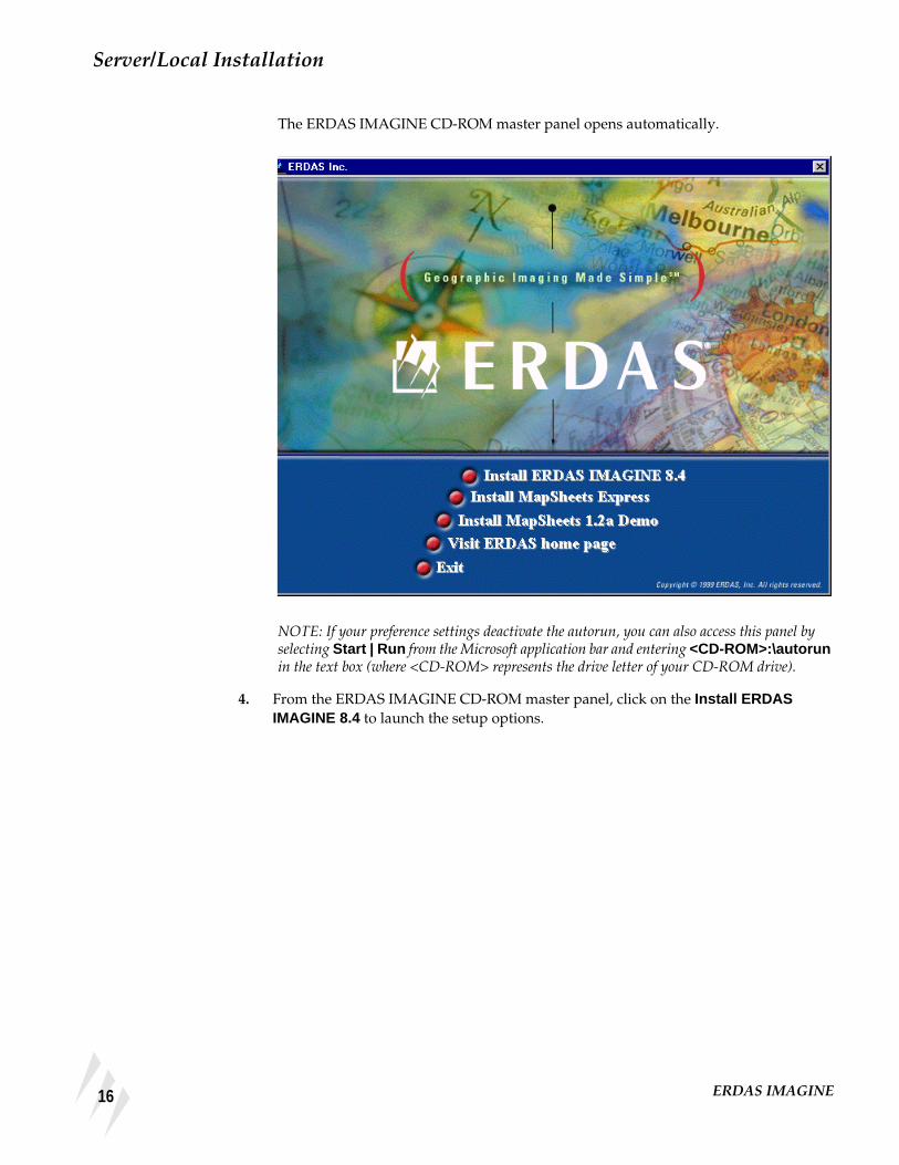
The Install ERDAS IMAGINE 8.4 accesses the setup dialogs to perform a Server/Localor Client installation of ERDAS IMAGINE.
The Install Mapsheets Express installs ERDAS Mapsheets Express1.2, a free viewerand mapping tool from ERDAS for working with imagery and vector map data. Thisviewer can be freely distributed with your data.
The Install Mapsheets 1.2a Demo installs a demo version of ERDAS MapSheets 1.2a,which can be purchased from ERDAS; see Install ERDAS IMAGINE 8.4 for furtherdetails.
The Visit ERDAS Home Page takes you directly to the ERDAS home page on the Web(www.erdas.com). If you are not connected to Microsoft Internet Explorer, or it is notyour default browser, a message prompts you to change browsers. This message canbe disabled after the first occurrence.
Running ERDASIMAGINE V8.3.1 and8.4
ERDAS IMAGINE V8.3.1 codewords cannot be used to secure ERDAS IMAGINE V8.4software. If you wish to run ERDAS IMAGINE V8.3.1 and ERDAS IMAGINE V8.4 atthe same time, you may choose one of the following options:
• install and license ERDAS IMAGINE V8.3.1 and ERDAS IMAGINE V8.4independently
13Installation Guide

Preparation for Installation under Windows
• use the license broker, Erdmaster, to secure both the ERDAS IMAGINE V8.3.1 andthe ERDAS IMAGINE V8.4 licenses.
If you choose to use Erdmaster to secure licenses for both ERDAS IMAGINE V8.3.1 andERDAS IMAGINE V8.4, enter your ERDAS IMAGINE V8.3.1 codewords (after theERDAS IMAGINE V8.4 codewords) while setting up ERDAS IMAGINE V8.4 security.Also, make sure that the ERDAS IMAGINE V8.4 license broker gets started beforerunning ERDAS IMAGINE V8.3.1 software.
For more information on running both ERDAS IMAGINE V8.3.1 and 8.4, see See“Erdmaster” on page 43.
14 ERDAS IMAGINE

CHAPTER 2Server/Local Installation
Description This section contains the steps for completing a Server/Local installation of ERDASIMAGINE software on a Windows NT 4.0 or Windows 98 system. The dialogs used inthe setup look the same regardless of system.
A server or local installation is one in which the program files are copied to themachine on which the installation is being performed. A server installation is onewhich serves ERDAS IMAGINE program files to a remote client machine usually viaa network connection. A local installation is one in which the ERDAS IMAGINEprogram files are run from the machine on which they are installed. Both of these typesof installation are the same.
You must have Administrator privileges to install ERDAS IMAGINE on a Windows NT4.0 operating system.
If you attempt to install ERDAS IMAGINE on a Windows NT 4.0 system withoutAdministrator privileges, a dialog opens instructing you that you are not able to installthe hardware security key driver.
Server/LocalInstallation
Follow these instructions to perform a Server/Local installation of ERDAS IMAGINE.
As with any hardware installation, it is recommended that you turn your computer offbefore inserting the hardware security key.
1. If this installation of ERDAS IMAGINE is going to act as the license broker for othermachines, or if this installation of ERDAS IMAGINE is locally licensed, install theERDAS-provided hardware security key on a parallel port.
This hardware device does not interfere with normal use of the parallel port. Simplyinsert it between the computer and any peripheral device using that port.
2. Start Microsoft Windows NT 4.0 or Windows 98.
You should close all running applications before installing ERDAS IMAGINE.
3. Insert the ERDAS IMAGINE installation CD into the CD-ROM drive.
15Installation Guide
Server/Local Installation
The ERDAS IMAGINE CD-ROM master panel opens automatically.
NOTE: If your preference settings deactivate the autorun, you can also access this panel byselecting Start | Run from the Microsoft application bar and entering <CD-ROM>:\autorunin the text box (where <CD-ROM> represents the drive letter of your CD-ROM drive).
4. From the ERDAS IMAGINE CD-ROM master panel, click on the Install ERDASIMAGINE 8.4 to launch the setup options.
16 ERDAS IMAGINE

Server/Local Installation
The ERDAS IMAGINE CD-ROM master panel remains active in the background andthe ERDAS IMAGINE V8.4 Setup window opens and fills the screen. The Welcomedialog opens, which directs you to close running applications.
NOTE: If, at any time, you wish to terminate the ERDAS IMAGINE Setup, click on theCancel button located at the bottom of the dialogs, select Exit Setup , and then click the Exitbutton located on the ERDAS IMAGINE CD-ROM master panel.
5. Click Next in the Welcome dialog.
17Installation Guide

Server/Local Installation
The License Agreement dialog opens. You can use the arrows or Page Down to viewall of the ERDAS Software License and Limited Warranty Agreement.
6. If you agree to the terms and conditions set forth in the ERDAS Software License andLimited Warranty Agreement, click Yes (if not, click No to cancel installation).
To aid you in completing your setup of ERDAS IMAGINE, an information dialogopens listing System Requirements. You can click the arrows or Page Down to scrollthrough all of the system requirements.
7. If your system meets or exceeds the requirements, click Next in the Information dialog.
18 ERDAS IMAGINE

Server/Local Installation
The Registration Information dialog opens. This dialog records your name and thename of your company.
8. Enter your name (or the Administrator’s name) in the Name text box.
9. Press the Tab key to move the cursor into the Company text box. Enter your Companyname.
10. Click the Next button at the bottom of the Registration Information dialog.
The Setup Type dialog opens. This dialog allows you to select the kind of installationyou are going to perform.
11. Click on the Server/Local installation type.
19Installation Guide

Server/Local Installation
12. Click the Next button at the bottom of the Setup Type dialog.
The Choose Destination dialog opens. This dialog allows you to specify the name ofthe installation directory on a server or a local computer. All files required to runERDAS IMAGINE are installed in this directory.
13. If you would like to change the installation directory, click the Browse button to accessthe Choose Folder dialog.
NOTE: If you would like to create a new directory in which to install ERDAS IMAGINE, typethe path in the text box.
14. Click to select or type the directory in which you would like to install ERDASIMAGINE.
15. Click the OK button to return to the Choose Destination dialog.
Select folder here
Select drive here
Enter new directory here
20 ERDAS IMAGINE

Server/Local Installation
16. Click the Next button at the bottom of the Choose Destination dialog.
17. The Backup Replaced Files dialog opens. This dialog allows you to choose a location forthe storage of files that are replaced by the current installation. This provides a meansof returning to a previous version if needed.
18. If you would like to change the backup directory, click the Browse button to access theChoose Folder dialog.
19. Click to select the directory in which you would like to save replaced files.
20. Click the OK button to return to the Backup Replaced Files dialog.
21. Click the Next button at the bottom of the Backup Replaced Files dialog.
The Select Components dialog opens. This dialog enables you to select ERDASIMAGINE modules and their components.
21Installation Guide

Server/Local Installation
22. Click to select the ERDAS IMAGINE modules you want to install in the left selectionbox.
23. Click to select the optional components of each module in the right selection box.
NOTE: Optional components vary depending on which modules you select. The Program Filescomponent is required for a module to function. The Disk Space Required and Disk SpaceRemaining fields also change based on your selections.
For example, if you have purchased ERDAS IMAGINE Professional and Vectormodules, and this is a new installation, you need to select at least the Program Filescomponents of Essentials, Advantage, Professional, Radar Interpreter, andVector modules.
The following table is provided to assist you when selecting install modules.
Select the desiredmodule componentsfrom this list
Program Files is arequired component fora module to function
Select modules youwish to installfrom this list
To Install TheseModules...
... You Must Select These (or they must already be installed).
Ess. Adv. Pro. RadarInt. Vector Virtual-
GISOrtho-BASE
Ortho-Radar
Stereo-SARDEM
IFSARDEM LZW
Essentials *
Advantage * *
Professional * * * *
Radar Interpreter * *
22 ERDAS IMAGINE

Server/Local Installation
*The Radar Interpreter may be installed as an add-on module or as part of IMAGINE Professional. Eitherway, it must be selected explicitly.
24. Click the Next button at the bottom of the Select Components dialog.
The Security Information dialog opens. This dialog contains the name and portnumber of the ERDAS license broker. If this is a remotely licensed installation, youmust change the name in the Computer field to the name of the license broker.
25. If the name displayed in the Computer text box is different than the name of the serveror local machine which provides security (license broker), enter the name of the licensebroker.
Vector * *
VirtualGIS * *
OrthoBASE * * *
OrthoRadar * * *
StereoSARDEM
* * *
IFSAR DEM * * *
LZW * *
To Install TheseModules...
... You Must Select These (or they must already be installed).
Ess. Adv. Pro. RadarInt. Vector Virtual-
GISOrtho-BASE
Ortho-Radar
Stereo-SARDEM
IFSARDEM LZW
23Installation Guide

Server/Local Installation
26. Do not change the number in the Port text box unless you know that it must be changed.
NOTE: If this installation of ERDAS IMAGINE is going to serve as the license broker, thenumber in the Port text box must also be assigned to the other computers secured by thismachine.
Use port number 5532 to serve ERDAS IMAGINE V8.2 and other previous versions ofERDAS IMAGINE.
27. Click the Next button at the bottom of the Enter Security Information dialog.
The Installation Settings dialog opens. In this dialog, you can use the arrows or PageDown to scroll and confirm that the options you selected are accurate. To makechanges, click the Back button to access previous dialogs.
28. If your selections are accurate, click the Next button at the bottom of the InstallationSettings dialog to begin the actual installation.
24 ERDAS IMAGINE

Server/Local Installation
A status bar displays, tracking the progress of the installation:
When finished, the Installation Complete dialog opens:
25Installation Guide

Server/Local Installation
29. Click Finish in the Installation Complete dialog. The following Install message isdisplayed:
30. Click the OK button to restart your computer.
31. Verify security information as described under "Server/Local Installation" on page 27.
32. Install codewords as described under "Server/Local Installation" on page 28.
33. If this machine is the license broker for remote machines, install erdmaster as describedin "Erdmaster" on page 43.
34. To start ERDAS IMAGINE, use the Microsoft task bar to select Start | Programs |ERDAS IMAGINE 8.4 and click the ERDAS IMAGINE 8.4 icon.
This runs the eml.exe program in <IMAGINE_HOME>\Bin\NTx86. As an alternate,a shortcut can also be made to ERDAS IMAGINE and placed on the desktop.
26 ERDAS IMAGINE

SysID Information
SysID Information Start the IMAGINE Properties tool from the Windows Start menu. Select Programs |ERDAS IMAGINE 8.4 | IMAGINE Properties .
The SysID tab reflects options you select during the installation process. This tab andthe Codewords tab are designed to give you direct access to all the security optionsyou need to run ERDAS IMAGINE software.
The System ID text box states either the ID of the hardware key, or that the driver orhardware key is not installed. If the driver is installed, its status is listed as present inthe Hardware Security Key Driver section. If the hardware key is installed, theSource text box indicates that is the case.
The Source text box indicates what type of licensing the ERDAS IMAGINEinstallation requires. If licensing is local, the text box shows Hardware Key . If licensingis remote, the text box shows System .
The Secure Master section of the SysID tab has a text box which names the computerwhere the hardware key is attached (license broker) as well as the port number. (Thisinformation corresponds to that which you provided in the Security Informationdialog, page 23.)
The Hardware Security Key Driver section of the SysID tab details whether or not thehardware key driver is present. If the driver is not present, click the Install Driverbutton and follow the instructions given under "Server/Local Installation" on page 30.
27Installation Guide

Server/Local Installation
Codewords If this is a new installation, there are no stored codewords. In this case, from theWindows Start menu select Programs | ERDAS IMAGINE 8.4 | IMAGINE Properties .Click the Codewords tab in the ERDAS IMAGINE Properties dialog.
1. Enter the ERDAS-supplied codewords in the Edit/Add Codeword text box at thebottom of the dialog, clicking the Add button after each codeword.
If you make a mistake when typing your codewords, click the Clear button or pressthe Backspace key. Invalid codewords are not accepted by the system.
NOTE: Codewords must be entered in the order that they appear on the ERDAS-supplied list.
If you prefer, you can enter the codewords into a text file for safe keeping and use theLoad from File button to read them in.
CAUTION: When read from a file, the system does not notify you of a bad codeword until youattempt to run IMAGINE.
For information on adding codewords for add-on modules, see Codewords for Add-onModules on page 29.
For information on entering codewords to run both ERDAS IMAGINE V8.3.1 and 8.4,see "Using V8.4 Security with Previous Versions of ERDAS IMAGINE Software" onpage 45
28 ERDAS IMAGINE

Codewords
2. After you have successfully added your codewords, click the Apply button.
3. Click the OK button in the ERDAS IMAGINE Properties dialog.
NOTE: If you have not restarted your computer since installing ERDAS IMAGINE, you mustdo so after installing the hardware key and driver for the installation to take effect.
Codewords for Add-onModules
Add-on modules for ERDAS IMAGINE also require codewords to execute thesoftware. In some cases, add-on modules can be chosen from the components listduring the installation of ERDAS IMAGINE. Add-on modules may also be suppliedon a separate CD.
Adding Modules During ERDAS IMAGINE Installation
After you have selected the ERDAS IMAGINE components including add-on modulesduring the installation process, you can add both types of codewords at the same time.Simply add the codewords to the Codewords tab of the ERDAS IMAGINE Propertiesdialog at the end of the installation process.
Adding Modules After ERDAS IMAGINE Installation
If you did not select add-on modules during the ERDAS IMAGINE installation, youmust install them separately. Follow the appropriate steps for Server/Local or Clientinstallation, selecting only the add-on module(s) from the Select Components dialog.Then, add the add-on module’s codewords to the Codewords tab of the ERDASIMAGINE Properties dialog at the end of the installation process.
Adding Modules from a Separate CD
Some add-on modules to ERDAS IMAGINE are provided on separate CD-ROMs. Inthis case, insert the CD into the appropriate drive and proceed with the installationinstructions provided with the add-on module. Then, input the codewords providedwith the add-on module into the Codewords tab of the ERDAS IMAGINE Propertiesdialog.
29Installation Guide

Server/Local Installation
Security Key Driver If the ERDAS IMAGINE installation is new and not an upgrade of an existing system,the Security Key Driver must be activated via the Sentinel Driver Setup Program. Thisprocess is automatic during installation of ERDAS IMAGINE. However, if you wish,this program may be accessed from the IMAGINE install directory.
1. To access the Sentinel Driver Setup Program, navigate to<IMAGINE_HOME>\install\skey\<system>\ and run Sentw95.exe or Setupx86.exedepending upon your system.
Where <IMAGINE_HOME> is the install directory and <system> is either Win_98 orWin_NT.
2. Select the Functions menu of the Sentinel Driver Setup Program, and choose InstallSentinel Driver .
The following dialog opens:
3. Type in the correct path, if required, and click OK.
The following message opens:
4. Click OK in the Sentinel Install dialog and restart your system.
30 ERDAS IMAGINE

Security Error Messages
Security ErrorMessages
The following messages may display when ERDAS IMAGINE programs checksecurity:
The <MODULE> expires in <n> days.
Please call ERDAS, Inc. to resecure.
This message applies to demo licenses and evaluation copies. It indicates that<MODULE> has been secured for a predefined time period, which expires in <n>days. Only programs that are secured for demonstration should display this messageand only during the last 5 days of the demo period. If you have any questions, pleasecontact the ERDAS Sales Department or your local distributor.
The <MODULE> is not authorized for this installation.
Please contact ERDAS, Inc. for authorization.
The requested <MODULE> has not been secured by the proper codeword
This module is not secured for this program version.
Please call ERDAS, Inc. to resecure.
The program that was run has a higher version number than the license broker isauthorized to permit. Either the program is wrong or the codeword is obsolete.
31Installation Guide

Server/Local Installation
32 ERDAS IMAGINE

CHAPTER 3Client Installation
Description This section contains the steps for completing a Client installation of ERDASIMAGINE software on a Windows NT 4.0 or Windows 98 system. The setup dialogslook the same regardless of system.
A client installation is one in which the IMAGINE program files reside on a server andonly a few necessary files are installed on the local machine. This decreasesperformance somewhat but requires minimal disk space.
You must have Administrator privileges to install ERDAS IMAGINE on a Windows NT4.0 operating system.
If you attempt to install ERDAS IMAGINE on a Windows NT 4.0 system withoutAdministrator privileges, a dialog opens instructing you that you are not able to installthe hardware security key driver.
Client Installation Use these instructions to perform a Client installation of ERDAS IMAGINE on acomputer connected to a server.
As with any hardware installation, it is recommended that you turn your computer offbefore inserting the hardware security key.
1. If this installation of ERDAS IMAGINE is locally licensed, install the ERDAS-providedsecurity hardware key on a parallel port.
This hardware device does not interfere with normal use of the parallel port. Simplyinsert it between the computer and any peripheral device using that port.
2. Start Microsoft Windows NT 4.0 or Windows 98.
You should close all running applications before installing ERDAS IMAGINE.
3. Insert the ERDAS IMAGINE installation CD into the CD-ROM drive.
33Installation Guide

Client Installation
The ERDAS IMAGINE CD-ROM master panel opens automatically.
NOTE: If your preference settings deactivate the autorun, you can also access this panel byselecting Start | Run from the Microsoft application bar and entering <CD-ROM>:\autorunin the text box (where <CD-ROM> represents the drive letter of your CD-ROM drive).
4. From the ERDAS IMAGINE CD-ROM master panel, click on the Install ERDASIMAGINE 8.4 to launch the setup options.
34 ERDAS IMAGINE

Client Installation
The ERDAS IMAGINE CD-ROM master panel remains active in the background andthe ERDAS IMAGINE V8.4 Setup window opens and fills the screen. The ERDASIMAGINE V8.4 Welcome dialog opens, which directs you to close runningapplications.
NOTE: If, at any time, you wish to terminate the ERDAS IMAGINE Setup, click on theCancel button located at the bottom of the dialogs, select Exit Setup , and then click the Exitbutton located on the ERDAS IMAGINE CD-ROM master panel.
5. Click Next in the ERDAS IMAGINE V8.4 Installation dialog.
35Installation Guide

Client Installation
The Software License Agreement dialog opens. You can use the arrows or Page Downto view all of the ERDAS Software License and Limited Warranty Agreement.
6. If you agree to the terms and conditions set forth in the ERDAS Software License andLimited Warranty Agreement, click Yes (if not, click No to cancel installation).
To aid you in completing your setup of ERDAS IMAGINE, an Information dialogopens listing system requirements. You can click the arrows or Page Down to scrollthrough all of the System Requirements .
7. If your system meets or exceeds the requirements, click Next in the Information dialog.
36 ERDAS IMAGINE

Client Installation
Next, the Registration Information dialog opens. This dialog records your name andthe name of your company.
8. Enter your name (or the Administrator’s name) in the Name text box.
9. Press the Tab key to move the cursor into the Company text box. Enter your companyname.
10. Click the Next button at the bottom of the Registration Information dialog.
The Setup Type dialog opens next. This dialog allows you to select which kind ofinstallation you are going to perform.
11. In the Setup Type dialog, click to select the Client installation type.
37Installation Guide

Client Installation
12. Click the Next button at the bottom of the Setup Type dialog.
In a Client installation, the Choose Existing Installation dialog opens. This folderalready contains all of the files required to run ERDAS IMAGINE.
13. Confirm that the location of the existing folder is accurate. If necessary, click Browse toselect another location. Click OK.
14. If you would like to change the installation directory, click the Browse button to accessthe Choose Folder dialog.
15. Click to select the directory from which you would like to install ERDAS IMAGINE.
16. Click the OK button to return to the Choose Existing Installation Folder dialog.
17. Click the Next button at the bottom of the Choose Existing Installation Folder dialog.
Select folder here
Select drive here
Enter directory name here
38 ERDAS IMAGINE
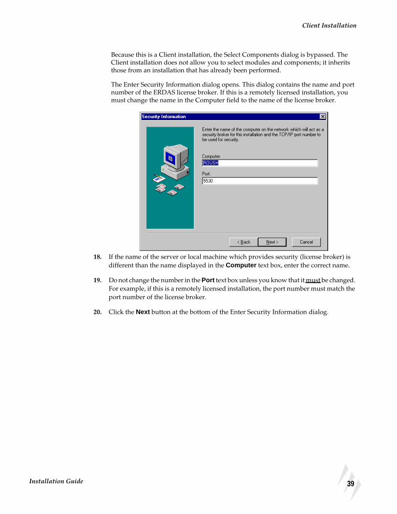
Client Installation
Because this is a Client installation, the Select Components dialog is bypassed. TheClient installation does not allow you to select modules and components; it inheritsthose from an installation that has already been performed.
The Enter Security Information dialog opens. This dialog contains the name and portnumber of the ERDAS license broker. If this is a remotely licensed installation, youmust change the name in the Computer field to the name of the license broker.
18. If the name of the server or local machine which provides security (license broker) isdifferent than the name displayed in the Computer text box, enter the correct name.
19. Do not change the number in the Port text box unless you know that it must be changed.For example, if this is a remotely licensed installation, the port number must match theport number of the license broker.
20. Click the Next button at the bottom of the Enter Security Information dialog.
39Installation Guide

Client Installation
The Start Installation dialog opens, displaying the settings you have selected. In thisdialog, you can use the arrows or Page Down to scroll and confirm that the options youselected are accurate. To make changes, click the Back button to access previousdialogs.
21. If your selections are accurate, click the Next button at the bottom of the StartInstallation dialog to begin the actual installation.
A status bar displays, tracking the progress of the installation:
40 ERDAS IMAGINE

Security Error Messages
When finished, the Installation Complete dialog opens.
22. Click Finish in the Installation Complete dialog. The following Install message isdisplayed.
23. Click the OK button to restart your computer.
24. Verify security information as described under "SysID Information" on page 27.
25. Install codewords as described under "Codewords" on page 28.
26. To start ERDAS IMAGINE, use the Microsoft task bar to select Start | Programs |ERDAS IMAGINE 8.4 and click the ERDAS IMAGINE 8.4 icon.
This runs the eml.exe program in <IMAGINE_HOME>\Bin\NTx86. As an alternate,a shortcut can also be made to ERDAS IMAGINE and placed on the desktop.
Security ErrorMessages
The following messages may display when ERDAS IMAGINE programs checksecurity:
1.The <MODULE> expires in <n> days.
Please call ERDAS, Inc. to resecure.
41Installation Guide
Client Installation
This message applies to demo licenses and evaluation copies. It indicates that<MODULE> has been secured for a predefined time period, which expires in <n>days. Only programs that are secured for demonstration should display this messageand only during the last 5 days of the demo period. If you have any questions, pleasecontact the ERDAS Sales Department or your local distributor.
2.The <MODULE> is not authorized for this installation.
Please contact ERDAS, Inc. for authorization.
The requested <MODULE> has not been secured by the proper codeword.
3.This module is not secured for this program version.
Please call ERDAS, Inc. to resecure.
The program that was run has a higher version number than the license broker isauthorized to permit. Either the program is wrong or the codeword is obsolete.
42 ERDAS IMAGINE

CHAPTER 4Erdmaster
Description This section explains the steps for preparing your Windows NT 4.0 system to installthe ERDAS IMAGINE license broker program, Erdmaster. If you are performing aServer/Local or Client installation with local licensing, you do not need the Erdmasterlicense broker.
The system setup and the software installation should be performed by anAdministrator who is familiar with the Windows system and its documentation.
You must have Administrator privileges to install ERDAS IMAGINE on a Windows NT4.0 operating system.
ERDAS SoftwareSecurity
When performing a Server/Local or Client installation with local licensing, security isbuilt-in and automatic. Each computer is individually secured with its own hardwarekey. If circumstances dictate, as in the case of a Server/Local or Client installation withremote licensing, you can secure all copies of the software from a single computer,called the license broker.
ERDAS IMAGINE software security is optionally controlled through the use of thelicense broker program that is always running on at least one computer in the network.This program is called Erdmaster. It secures all copies of ERDAS IMAGINE softwarethat operate on the network. Each license broker must have a hardware key and a setof codewords.
If you wish to use remote licensing, you must determine which workstation(s) the ERDASIMAGINE security program, Erdmaster, is going to reside on before you begin installingERDAS IMAGINE software.
All ERDAS IMAGINE programs communicate with Erdmaster using TransportControl Protocol/Internet Protocol (TCP/IP). TCP/IP must be configured on eachmachine that relies on Erdmaster for security.
See your Windows documentation or on-line help for more information on TCP/IP.
Installation Two tasks must be performed prior to accessing a remote license broker:
• Start TCP/IP services on all ERDAS IMAGINE workstations.
• Start the license broker program (Erdmaster).
43Installation Guide

Erdmaster
If you are installing the ERDAS IMAGINE license broker software on a computer thatis connected to a network with other computers running ERDAS IMAGINE, performthe procedures below.
Start TCP/IP Services Make sure that the TCP/IP services are started on each computer running ERDASIMAGINE in the system. Use the following procedure to install TCP/IP services onthese machines.
1. Select Start | Settings | Control Panel from the Microsoft task bar.
2. Double-click the Network icon.
3. Click the Protocols tab in the Network dialog.
4. If TCP/IP Protocol is not listed under Network Protocols , add it using the Add button.
5. The hostname and the IP address of each computer on which ERDAS IMAGINE runsmust be listed in your hosts file or be accessible through a Domain Name Server (DNS).To edit the hosts file, use Notepad to open (or create) the directory called<WindowsDir>\system32\drivers\etc\hosts for Windows NT 4.0, or the directorycalled <WindowsDir>\hosts for Windows 98.
Start the License Broker During the installation of ERDAS IMAGINE, you are asked for the name of thecomputer where Erdmaster is installed.
See the Security Information dialog.
NOTE: The port number you assign in the Security Information dialog must be assigned to allmachines which use Erdmaster for security.
1. Install ERDAS IMAGINE on the computer which is going to act as the license broker,as described in "CHAPTER 2: Server/Local Installation".
2. If you specified the local machine, use the Microsoft task bar to select Start | Programs| ERDAS IMAGINE 8.4 | Install Erdmaster Service . Select this menu option to startErdmaster services.
If you specified a remote machine, Erdmaster must be installed and started on thatsystem as described above.
Autostart the LicenseBroker
If you want Erdmaster to start automatically on reboot, login as Administrator and usethe following procedure.
1. Use the Microsoft task bar to click Start | Settings | Control Panel .
2. Double-click the Services icon and select Erdmaster from the Service list.
3. Click the Startup button.
4. In the Service dialog, select the Automatic radio button in the Startup Type group.
5. Click OK.
44 ERDAS IMAGINE

Using V8.4 Security with Previous Versions of ERDAS IMAGINE Software
Stop the License Broker To stop Erdmaster, click Start | Programs | ERDAS IMAGINE 8.4 | Stop ErdmasterService .
Remove the LicenseBroker
To remove Erdmaster, click Start | Programs | ERDAS IMAGINE 8.4 | RemoveErdmaster Service .
Using V8.4 Securitywith PreviousVersions of ERDASIMAGINE Software
To run ERDAS IMAGINE V8.4, you must obtain a new set of key codes.
You can use the ERDAS IMAGINE V8.4 license broker for running previous versionsof ERDAS software. It is recommended that you use only a single license broker for allof your ERDAS software.
NOTE: When you enter your ERDAS IMAGINE V8.4 codewords, also enter all of yourcodewords for all previous versions of ERDAS IMAGINE. First, enter your V8.4 codewords,then enter your V8.3.1 codewords. If you have older versions of ERDAS IMAGINE, continueto enter the codewords in descending order.
Use port number 5532 to serve ERDAS IMAGINE V8.2 and previous versions ofERDAS IMAGINE.
45Installation Guide

Erdmaster
46 ERDAS IMAGINE
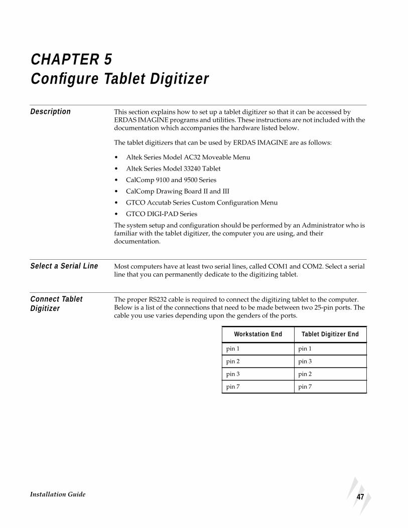
CHAPTER 5Configure Tablet Digitizer
Description This section explains how to set up a tablet digitizer so that it can be accessed byERDAS IMAGINE programs and utilities. These instructions are not included with thedocumentation which accompanies the hardware listed below.
The tablet digitizers that can be used by ERDAS IMAGINE are as follows:
• Altek Series Model AC32 Moveable Menu
• Altek Series Model 33240 Tablet
• CalComp 9100 and 9500 Series
• CalComp Drawing Board II and III
• GTCO Accutab Series Custom Configuration Menu
• GTCO DIGI-PAD Series
The system setup and configuration should be performed by an Administrator who isfamiliar with the tablet digitizer, the computer you are using, and theirdocumentation.
Select a Serial Line Most computers have at least two serial lines, called COM1 and COM2. Select a serialline that you can permanently dedicate to the digitizing tablet.
Connect TabletDigitizer
The proper RS232 cable is required to connect the digitizing tablet to the computer.Below is a list of the connections that need to be made between two 25-pin ports. Thecable you use varies depending upon the genders of the ports.
Workstation End Tablet Digitizer End
pin 1 pin 1
pin 2 pin 3
pin 3 pin 2
pin 7 pin 7
47Installation Guide

Configure Tablet Digitizer
Switch Settings andFormats
When you are using ERDAS IMAGINE with the supported tablet digitizers, werecommend the specified switch settings and data formats.
Altek Series Model AC32Moveable Menu
a This format corresponds with the ALTEK format number 4.Altek Series Model 33240Tablet
Switch Settings for the Left Bank
Switch Settings for the Right Bank
Serial Speed 9600 bps
Serial Misc. 1 stop bit / 8 data bits / No parity
Emulation ALTEK
Format F12 a F XXXXX YYYYY
Rate 50 pts/sec
Resolution .001 inch
Run Type Type 1
Mode Point
Miscellany CR on / LF on / CTS off
ERDASIMAGINEFormat
Switch 1 Switch 2 Switch 3 Switch 4 Switch 5 Switch 6 Switch 7 Switch 8
1 on off on on on on on off
2 on off on on on on on off
3 on off on on on on on off
4* on off on on on on on off
5 on off on on on on on off
6 on off on on on on on off
7 on off on on on on on off
48 ERDAS IMAGINE

Switch Settings and Formats
*Format 4 is the default. ERDAS IMAGINE does not support format 6. You may need touse a swap cable.
CalComp 9100 Series
Switch Settings for SB1
a These settings are set at the factory and should not be changed.
*Format 4 is the default.
Switch Settings for SW1
Switch Settings for SW2
ERDASIMAGINEFormat
Switch 1 Switch 2 Switch 3 Switch 4 Switch 5 Switch 6 Switch 7 Switch 8
1 on off off off on on on on
2 on off off off on on on off
3 on off off off on on off on
4* on off off off on on off off
5 on off off off on off on on
6 on off off off on off on off
7 on off off off on off off on
ERDASIMAGINEFormat
Switch 1 Switch 2 Switch 3 Switch 4 Switch 5 Switch 6Switch
7aSwitch
8a
1 close open close close close close close open
2 close open close open close close close open
3 close open open close close close close open
4* close open open open close close close open
SW1Switch 1
SW1Switch 2
SW1Switch 3
SW1Switch 4
SW1Switch 5
SW1Switch 6
SW1Switch 7
SW1Switch 8
All ERDASIMAGINEFormats
open open close close open close close open
49Installation Guide

Configure Tablet Digitizer
CalComp 9500 Series Operating Mode and Resolution Switch Settings for Area 1
Soft Switch Settings for Area 1
*Format 4 is the default.
Switch Settings for Area 2 (Port A) Only
SW2Switch 1
SW2Switch 2
SW2Switch 3
SW2Switch 4
SW2Switch 5
SW2Switch 6
SW2Switch 7
SW2Switch 8
All ERDASIMAGINEFormats
close open close open close close close close
Operating Mode SwitchResolution(1000 LPI)
Switch
Point on 1 off
Run off 2 on
Track off 3 on
Line off
INC off
Prompt off
ERDASIMAGINEFormat
Switch 1 Switch 2 Switch 3 Switch 4 Switch 5
1 off off on off off
2 off off on off on
3 off off on on off
4* off off on on on
Baud Rate(9600)
SwitchDataBits
SwitchParity(none)
Switch Stop Bit Switch
1 off 7 off 1 on Stop 1 off
2 off 8 on 2 off Stop 2 off
3 on 3 off
50 ERDAS IMAGINE

Switch Settings and Formats
The switch settings for CalComp 9500 areas 3 (Port B), 4, and 5 are not applicable.
CalComp Drawing BoardII and III
Soft Switch Settings for A
Soft Switch Settings for B
Soft Switch Settings for C (Drawing Board III Only)
*Format 3 is the default.
Transmit/Receive
SwitchLineFeed
Switch Port A Switch Echo Switch
TX 2/3 on LF off Port on Echo Off
ERDASIMAGINEFormat
Switch 1
Switch 2
Switches 3-5
Switches 6-10
Switches11-13
Switch 14
Switch 15
Switch 16
Switch 17
Switch 18
1 off on off on off on off off off on
2 off on off on off on off on off on
3* off on off on off on on off off on
4 off on off on off on on on off on
Switches1-2
Switches3-4
Switches5-7
Switch 8Switches
9-17Switch 18
All ERDASIMAGINEFormats *
off on off on off on
Switch 1 Switch 2 Switch 3 Switch 4 Switch 5 Switch 6 Switch 7
All ERDASIMAGINEFormats
off off off off off N/A off
51Installation Guide

Configure Tablet Digitizer
GTCO Accutab SeriesCustom ConfigurationMenu
*Format 4 is the same as ERDAS IMAGINE format 7.
GTCO DIGI-PAD Series Switch Settings for S1
Switch Settings for S2
CommunicationOptions
Mode Options Menu Codes Output Format Options
Baud9600
ModePoint ERDAS
IMAGINE8.X
04*
GTCOASCII
Data Bits 8 Resolution 1000 lpi
Stop Bits 1
Parity None
S1Switch 1
S1Switch 2
S1Switch 3
S1Switch 4
S1Switch 5
S1Switch 6
S1Switch 7
S1Switch 8
All ERDASIMAGINEFormats
off off on on off off off on
ERDASIMAGINEFormat
Switch1
Switch2
Switch3
Switch4
Switch5
Switch6
Switch7
Switch8
1 off off on on off off off off
2 off on on on off off off off
3 on off on on off off off off
4 on on on on off off off off
5 off off on on on off off off
6 off on on on on off off off
7* on off on on on off off off
8 on on on on on off off off
52 ERDAS IMAGINE

Connect to HyperTerminal
*Format 7 is the default. You may need to use a swap cable with port B, but not withport A.
Switch Settings for S3
Connect toHyperTerminal
Once you connect the tablet digitizer to a COM port on your computer, perform thefollowing procedures to ensure that the two are communicating.
From the Microsoft task bar, select Start | Programs | Accessories | Hyperterminal| HyperTerminal . For Windows 98, select Start | Programs | Accessories |Communications | HyperTerminal .
NOTE: If this is the first time you have accessed the HyperTerminal, you are instructed to enterinformation regarding location and modem. Follow the instructions, then proceed as directedbelow. If you do not have a modem, click No in the HyperTerminal message box.
The HyperTerminal dialog opens along with the Connection Description dialog.
6. In the Connection Description dialog, enter a name for the connection, and click OK.
S3Switch 1
S3Switch 2
S3Switch 3
S3Switch 4
S3Switch 5
S3Switch 6
S3Switch 7
S3Switch 8
All ERDASIMAGINEFormats
off off off off on off off off
Click OK
53Installation Guide

Configure Tablet Digitizer
7. In the Connect To dialog, confirm that the Connect using field correctly identifies theport to which the tablet digitizer is attached, and click OK.
The COM1 Properties (or COM2 if you selected it in the Connect using field) dialogopens:
8. Change the Bits per second to 9600, and then click OK.
Click OK
Bits per second
Click OK
54 ERDAS IMAGINE

Configuring the Tablet Digitizer
To confirm that the tablet digitizer is functioning correctly, use the pointing device toclick various areas on the tablet digitizer. The data is presented in the HyperTerminalwindow as depicted below:
9. Close the HyperTerminal.
Configuring theTablet Digitizer
From within ERDAS IMAGINE, you are prompted to specify the type of tabletdigitizer, the data format and the port name that you want to access for output. Afteryou complete this setup, the tablet digitizer is operational with ERDAS IMAGINE foruse with various applications which can use the tablet, such as vector editing, the GCPeditor, etc. Following is an example of connecting to a tablet from an ERDASIMAGINE application.
1. With a Viewer open and an image displayed, select File | New | AOI .
2. Select AOI | Tablet Input | New Configuration .
The Tablet Setup dialog opens:
3. In the Tablet Setup dialog, select the name of the digitizing tablet from the Tabletpopup list.
Tablet popup list
55Installation Guide

Configure Tablet Digitizer
4. Select the tablet digitizer format from the Format popup list. This is the format numberfrom the tables in the section See “Switch Settings and Formats” on page 48..
5. Select the serial port to which the tablet digitizer is connected from the Port popup list.
6. Click the OK button.
For further help, see the ERDAS IMAGINE On-Line Help for more information onsetting up the tablet digitizer within ERDAS IMAGINE.
56 ERDAS IMAGINE

CHAPTER 6Configure Tape Drive
Description This section explains how to set up a tape drive so that it can be accessed by ERDASIMAGINE programs and utilities.
You must have Administrator privileges to configure peripherals on a Windows NT 4.0operating system.
Local Tape Drive(Windows NT only)
Use these instructions to configure a tape drive on a local machine with a Windows NT4.0 operating system. The tape drive and SCSI adaptor should already be installed onyour local machine.
There is no local tape support for Windows 98.
1. From the Start button on the Microsoft task bar, select Settings | Control Panel .
2. From the Control Panel , select the Tape Devices icon by double-clicking on it.
The Tape Devices dialog opens, stating that a tape device is not found.
3. In the Devices tab of the Tape Devices dialog, click the Detect button.
A status bar displays as the system scans for tape devices.
57Installation Guide

Configure Tape Drive
Once the tape device is located, it is listed in the window of the Devices tab as shownbelow.
4. Click the Properties button to confirm that both the Device Status and SCSI AdapterInformation are correct, then click OK in the Properties dialog.
5. Click the Drivers tab.
A status bar opens briefly as the system creates a list of installed drivers. The Driverstab of the Tape Devices dialog should now look similar to the one pictured below:
6. Click OK in the Tape Devices dialog. The Tape Devices dialog closes.
For help with installing, detecting, and viewing information about a tape device, seeWindows on-line help.
58 ERDAS IMAGINE

Configuring a Remote Tape Drive
Configuring aRemote Tape Drive
You must use the ERDAS IMAGINE Configuration Editor to define a remote tapedrive for ERDAS IMAGINE.
1. Select Session | Configuration in the ERDAS IMAGINE menu bar. The ConfigurationEditor opens:
2. From the Configuration Class popup list, select tapes .
3. Click the Directory popup list and select one of the following options:
Global = <IMAGINE_HOME>/etcThe setup and preferences for the current device are accessible by all ERDASIMAGINE users working from the same ERDAS IMAGINE installation. You cannotsave to the global environment unless you are the Administrator who installed theERDAS IMAGINE software.
When you have the Global directory option selected for a configuration class, only theglobal configuration information is accessible from the rest of the ERDAS IMAGINEuser interface for this configuration class. This allows an Administrator to test only theglobal changes and it prevents the Administrator's User preferences frominadvertently being saved to the global database.
59Installation Guide

Configure Tape Drive
User = <HOMEPATH>/.imagine840The setup and preferences for the current device are accessible only by you (wheneveryou are logged into the same account). Your User preference changes to a globallyconfigured device take precedence over the Global preference settings for your ERDASIMAGINE sessions.
NOTE: The changes you make in the Configuration Editor take effect immediately in thecurrent ERDAS IMAGINE session. They are also retained for the current ERDAS IMAGINEsession even if they have not been saved. This allows Global changes to be tested in the currentERDAS IMAGINE session without affecting users sharing the same installation of ERDASIMAGINE.
If all of your User preferences do not appear to be reflected in the ERDAS IMAGINE userinterface, verify that the User option is selected in the Directory popup list for the appropriateConfiguration Class(es) in the Configuration Editor.
The File window shows you the file name to be used when you save the setup andpreferences for the current configuration class. The default is tapes.cfg .
4. Click the New button to add a new tape drive using the tape template filter. The Createnew device dialog opens.
5. In the Name text box of the Create new device dialog, enter a name for the device. Thisis the name that appears in the ERDAS IMAGINE dialogs as an I/O device option. Afteryou enter the name, press the Return key for the name to be accepted, then click OK.
6. Click in the Tape Model text box and enter the model name of the tape drive you wishto add. This is for your information only.
7. Click in the Tape drive host text box and enter the hostname of the workstation towhich the tape drive is actually attached.
8. Click in the Tape drive device file text box and enter the tape drive number you wishto add.
60 ERDAS IMAGINE

Configuring a Remote Tape Drive
Enter the tape drive device file for that tape device. For example, you might enter/dev/rst0 for a QIC/150 tape drive connected to a Sun workstation.
If the host to which the tape device is attached is running Sun OS version 5.6 (Solaris 2.6or 2.7) or greater, the tape drive device file must include the “b” flag, indicating that BSDcompatibility is desired (e.g. /dev/rmt/0b ).
9. When you have finished filling in the information, select File | Close.
The following message displays:
10. To save your changes to the Configuration Editor, click Yes.
61Installation Guide

Configure Tape Drive
Configuring aRemote Tape Driveon a UNIX Machine
The ERDAS IMAGINE Configuration Editor enables you to access a tape drive acrossa network. The following steps must be performed before you can load data to or froma remote tape drive.
NOTE: You cannot access a remote tape drive connected to a UNIX machine if the UNIXmachine does not have IMAGINE Essentials configured.
The remote workstation refers to the workstation to which the tape drive is attached.The local workstation refers to the workstation where you are currently runningERDAS IMAGINE software.
Automatic Tape ServerStart-up at Time ofSystem Boot
1. In order to have the tape server start on a remote workstation every time the remotesystem boots, ERDAS IMAGINE software must either be installed on the remoteworkstation or it must be NFS-mounted at boot time. ERDAS IMAGINE software doesnot necessarily have to be accessible on the remote workstation from the same directoryas the local workstation.
2. The tape server must be invoked from a system start-up script (e.g., /etc/rc.3 on SunSolaris 2.6 or 2.7 systems) at boot time on the remote workstation with the followingcommand:
<IMAGINE_HOME>/bin/emta_start
Replace <IMAGINE_HOME> with the directory from which ERDAS IMAGINEsoftware is accessible on the remote workstation. The change to the system start-upscripts generally requires root user authority.
3. Proceed to See “Set Up Tape Drive” on page 62.
Set Up Tape Drive Use the Configuration Editor to set up and configure the tape drive for the remoteworkstation.
NOTE: The configuration can be performed from either the local or remote workstation.
62 ERDAS IMAGINE

CHAPTER 7Adding Fonts to Annotation
Introduction This section describes how to add new fonts to ERDAS IMAGINE annotation.
Create an .fdb File To add True Type system fonts to the ERDAS IMAGINE annotation package, you mustadd the new fonts to a font data base (.fdb) file in any of the directories specified in theERDAS_FONT_PATH, which is, by default, the <IMAGINE_HOME>/etc/fontsdirectory where ERDAS IMAGINE is installed on your system.
You can create a new file or edit an existing file. You may use<IMAGINE_HOME>/etc/fonts/fontlist.fdb as an example, but be aware that thecontents of the fields may look different for the OTL fonts that are distributed withERDAS IMAGINE, and that your file should only have entries for your fonts.
If you create a new file, you can give it any name as long as it is in one of the directoriesmentioned above. User-defined directories may be used by adding them to theERDAS_FONT_PATH environment variable in the Environment tab of the ERDASIMAGINE Properties dialog. Note that a file named “a.fdb” in the current directoryoverrides a file named “a.fdb” in the directory from which you started ERDASIMAGINE, which in turn overrides a file named “a.fdb” in the etc/fonts directory.
The first line of the .fdb file must be version 3.
You must have a seven-field entry in your .fdb file for every font you want theannotation package to know about. All of the name and string fields in the entryshould be in quotes.
The following chart lists these fields and the information they specify.
Field Number Field Name Font Information 1
One Font Name Use the Font File Name below (withoutvariations) or use another name of your choice.This is the name you see in the scrolling list ofavailable fonts in the Text Style Chooser, plusany special weight and/or slant attributes. 2
Two Font File Name This field is the Font Name as shown in FontsControl Panel.
63Installation Guide

Adding Fonts to Annotation
1 This information is not an actual description of the fields in the .fdb, files, but instructions on where to findthe information for the True Type fonts you are adding.
2 Weight attributes that are recognized in the Text Style Chooser are “Extra-Bold,” “SemiBold,” “Bold,”“Heavy,” “Medium,” “Light” and “Thin;” the only slant attribute that is recognized is “Italic.”
3 This file must be in the $IMAGINE_HOME/etc/fonts directory. If you do not have a downloadable ASCIIPostScript font file for this font, use the word “none.”
Three ASCII PostScript File Name This is a printer-downloadable file that goeswith the selected font. It is the font file that isincluded in the EPS file that is created when yououtput your Map Composition to an EPS file.When you transfer the EPS file to anotherapplication (e.g., Microsoft Word) and print thedocument, this file is actually downloaded toyour PostScript printer. If you do not specify aPostScript file in this field, you are not able tocreate a usable file.3
Four Windows Font Name When a font is selected, the Windows fontspecified here is used in the annotation textentry fields, where text is entered or displayed.If you just want the standard ERDAS IMAGINEtext font to be used, use the word “default” Ifyou want the font that you are adding to bedisplayed in the text entry fields, use the samename here that you used for the font file name(Field Number Two).
Five Font Language Flag This is the only field that must not be in quotes.It is the flag that indicates whether the languagefor which this font is used is written left-to-rightor right-to-left. If the language is written left-to-right, use LEFT_TO_RIGHT for this field. If thelanguage is written right-to-left, useRIGHT_TO_LEFT for this field.
Six Sample String This is the string that you want to use for thetext style sample in the Text Style Chooser. ForEnglish, something like “AaBbCc” or Abc123” iscommonly used, but you may wish to use someother string, particularly for other alphabets.
Seven Font Server Name This is the name of the font server to be used toread the font. Use “MSW” for this field.
Field Number Field Name Font Information 1
64 ERDAS IMAGINE

Example .fdb Entries
Example .fdb Entries Below is an example of an entry in an .fdb file for a font that uses the standard ERDASIMAGINE font in the text entry fields.
Arial Thin
Arial Narrow
arial.ps
“default”
LEFT_TO_RIGHT
“AaBbCc”
“MSW”
The fields are printed on separate lines for space reasons. They should all be on one line inthe .fdb file.
Below is an example of an entry for a font for which there is no downloadablePostScript file. This example uses the same font for the text entry fields as for theannotation itself.
“Suu kyi”
“Suu kyi”
“none”
“Suu kyi”
LEFT_TO_RIGHT
“AaBbCc”
“MSW”
See $IMAGINE_HOME/etc/fonts/fontlist.fdb for other examples.
65Installation Guide

Adding Fonts to Annotation
66 ERDAS IMAGINE

CHAPTER 8Windows Printing
Introduction This chapter provides information about how to set up your map composition forprinting.
67Installation Guide

Windows Printing
This is the map composition used in the following example. The map compositionmeasures 48” × 68”.
NOTE: This map composition is not included in the <IMAGINE_HOME>/examplesdirectory.
This document is based on the premise that the printing to be done can be executed onan HP plotter using an HPRTL print driver on either Windows NT or Windows 98(preferably Windows NT).
Troubleshooting Sometimes when you are trying to print a map, system resources are consumed by theprinting process, and the attempt to plot fails. There are several ways in which aprinting failure might manifest itself. Depending on the type of print device beingused, the indications of failure vary. The most common, of course, is that you do notsuccessfully print the desired map. The symptoms of failure shown below are commonfor HP 600 to 3500 plotters. This includes the 1055 series.
Out of Memory/Data Lost This is a printer panel message that is displayed when the printing applicationoverwhelms the printer memory with data. This commonly occurs when postscriptprint drivers are used to attempt a print job that sends more data to the print devicethan the print device has memory to handle.
In ERDAS IMAGINE V8.4, this situation can also occur if you do not choose toRasterize before printing . In the case where the you do not choose to Rasterizebefore printing , the map composition should be processed using the In computermemory option. Commonly, when the system runs out of memory, the composition ispartially printed. It is not unusual that whole elements of the map composition mightbe missing.
Nothing Prints In another example, you send your map composition to print, and the process initiatessuccessfully. However, as soon as the print job switches from spooling to printing, thejob is deleted from the queue. There are no results to speak of. The only potential errormessage is from the NT OS: Your system is running low on virtual memory.Please close some applications. This is dependent on your system’s virtualmemory settings.
It is advisable that you increase the default NT virtual memory settings. On MicrosoftNT systems, there are initial and maximum size settings for the virtual memory thatare made available to applications. The default minimum memory is acceptable, butthe overall may need to be increased.
Changing Memory Settings
Increasing overall memory can be accomplished by:
• increasing the maximum on the existing paging file.
• creating an additional paging file (if there is not sufficient free disk space on thedrive or partition where the other paging has been created).
68 ERDAS IMAGINE

Troubleshooting
It is also common that, when the Commit Charge value on the Windows NT TaskMangler exceeds ~ 1 GB, nothing prints. Eventually, this occurs when processingwithout Rasterize before printing and In computer memory.
Preferences Strip Height
The Strip Height is set to 64 by default. This is an acceptable strip height. This is theheight of each strip of data that is sent to the plotter.
Printing Data Transfer Compression
Printing Scale Factor is the scaling factor at which the output data is created. This scaleapplies to the output frame size. For example:
none = 1x
low = 2x
medium = 4x
high = 8x
For example, if the image that is being put into a frame is 5000 × 6000 pixels, and theframe in which the image data is going to be printed is 17”× 20”, and you are plottingat 600 dpi, then there are 5000 pixels with which to fill 10200 dots.
Scaling is always constrained to the smaller of the dimensions to maintain geometricfidelity. In the example above, a scaling factor of 2 would be appropriate. If a scalingfactor of one were used, ERDAS IMAGINE would create a file big enough to fill theoutput map frame. This is, in essence, quadrupling the size of the raster data neededto be sent to the plotter.
Moreover, a scale factor of two is a good trade-off in that little annotation degradationoccurs. If the Printing Scale Factor is too high, text annotation can become pixelated.
Spool RAW Data In order to print successfully in ERDAS IMAGINE, data must be spooled to the printeras the RAW datatype. These steps show you how to set your printer driver to alwaysspool the RAW datatype.
1. From the Windows Start button, click Settings | Printers to display the WindowsPrinters dialog:
69Installation Guide
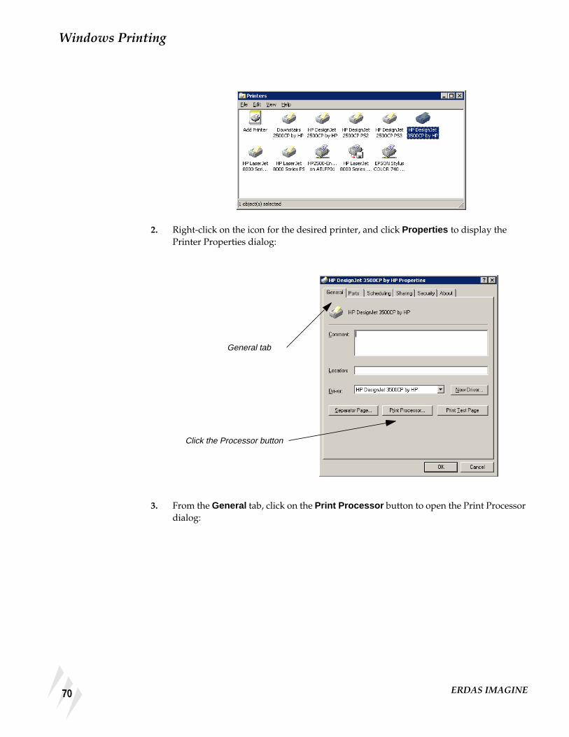
Windows Printing
2. Right-click on the icon for the desired printer, and click Properties to display thePrinter Properties dialog:
3. From the General tab, click on the Print Processor button to open the Print Processordialog:
General tab
Click the Processor button
70 ERDAS IMAGINE

Troubleshooting
4. Check the Always spool RAW dataype checkbox.
Changing the Locationof the Spool Folder
In Windows NT, the default spool folder is inC:\WINNT\System32\spool\PRINTERS. This is only applicable if Windows NT isinstalled on drive C. It is common that the drive on which Windows NT is installedmay not have sufficient free disk space for spooling large print jobs. In order tosuccessfully print large print jobs, it is sometimes necessary to change the location ofthe spool folder. This can be accomplished as follows:
1. From the Windows Start button, click Settings | Printers to display the WindowsPrinters dialog.
2. Select File | Server Properties from the Printers dialog. The Print Server Propertiesdialog opens. Click on the Advanced tab:
3. In the Spool Folder field, change the path of the spool folder to a folder on a drive thathas adequate free disk space, such as: C:\WINNT\System32\spool\PRINTERS.
Check the Always spoolRAW datatypecheckbox
The Advanced Tab
71Installation Guide

Windows Printing
Scenarios You may encounter the following scenarios when printing:
No Pre-Rasterize These steps work for a moderate size map composition (e.g., 24” × 36” at 600 dpi). Theno pre-rasterize scenario does not create a temporary file: all processing is handled inmemory. This scenario can lead to the situation where nothing prints when the limitsof system memory are exceeded. (There appears to be a 1 GB limit in Windows NT 4.0.)Any time the Commit Charge exceeds 1 GB, the print job is removed from the queue.
Preparation
ERDAS IMAGINE must be running.
You must have a map composition displayed.
NOTE: The map composition displayed in this scenario is not supplied with the examples data.You may want to use the following steps to print the map composition you created in"CHAPTER 3: Map Composer", in the ERDAS IMAGINE Tour Guides.
The following picture shows a Map Composition ready to print:
Open the Map Composition Dialog
1. In the Map Composer dialog, click the Print icon.
72 ERDAS IMAGINE

Scenarios
This brings up the Print Map Composition dialog. The Print Map Composition dialogopens on the Printer tab. In this tab, you can select a printer you have configured.
For information about how to configure a printer, see the most recent ERDAS IMAGINEInstallation Guide.
2. Click the Print Destination dropdown list and choose an appropriate printer.
NOTE: If you do not have any printers configured on your computer, then the only options thatappear are Image File and EPS File.
The Print Destination you select displays in the Print Map Composition dialog. Now,you can set configuration parameters.
The Printer tab allows you toselect a configured printer thatcan print the map composition
In this example, the HPDesignJet 2500CP by HP printeris chosen as the Print Destination
73Installation Guide

Windows Printing
3. Click on the Change printer configuration button.
The Properties dialog for the printer you select displays. In this case, the title of thedialog is HP DesignJet 2500CP by HP.
4. Click on the More sizes button.
The Paper Sizes dialog opens. In this dialog, you can set the paper size required foryour particular map composition.
Click the Change printerconfiguration button
The printer you chosedisplays in the PrintDestination window
In the Properties dialog,click on the More sizesbutton
74 ERDAS IMAGINE

Scenarios
5. Click in the Custom paper size section of the Paper Sizes dialog and type the size ofthe paper. In this case, the appropriate size is 36” × 26”.
6. Click OK in the Paper Sizes dialog.
You are returned to the Paper Size tab of the Properties dialog.
7. In the Paper Size tab of the Properties dialog, click the Landscape orientation radiobutton. This option conserves paper.
8. Click the Layout View tab in the Properties dialog.
The Layout View information displays.
Set custom papersize in this area
Choose the Landscapeorientation
75Installation Guide

Windows Printing
The Layout View tab shows that the width is 36”, and the height is 26”. The 36”dimension runs across the 36” width of the roll of paper.
9. Click the Options tab in the Properties dialog.
The options display. In this tab you make color and paper selections.
10. In the Options tab, click the checkbox for Manual color .
You are going to come back to the Color control setting in a moment.
76 ERDAS IMAGINE

Scenarios
11. Click the Paper type dropdown list, and select the type of paper.
The Quality setting controls the dots per inch (dpi) that is used to plot the map. Thereare different quality designations used by different printer drivers. Some common HPquality designations are:
• Fast (draft) (300 dpi)
• Normal (final) (300 dpi)
• Best (enhanced) (600 dpi)
• Economy (300 dpi)
• Productivity (300 dpi)
• Photo (600 dpi)
12. Click on the Advanced tab in the Properties dialog.
The advanced options display in the Properties dialog.
So far, you have selectedthe Manual color radiobutton as well as the Papertype
77Installation Guide
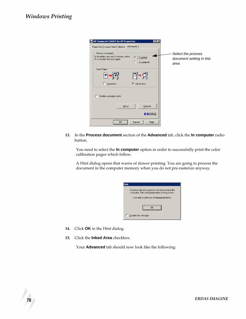
Windows Printing
13. In the Process document section of the Advanced tab, click the In computer radiobutton.
You need to select the In computer option in order to successfully print the colorcalibration pages which follow.
A Hint dialog opens that warns of slower printing. You are going to process thedocument in the computer memory when you do not pre-rasterize anyway.
14. Click OK in the Hint dialog.
15. Click the Inked Area checkbox.
Your Advanced tab should now look like the following:
Select the processdocument setting in thisarea
78 ERDAS IMAGINE

Scenarios
Color control
1. Click the Options tab in the Properties dialog.
2. Click on the Color control button in the Options tab.
The Color Control dialog opens.
3. In the Printed color control section of the Color Control dialog, click on the Userdefined color correction radio button.
4. Click on the Start Color Correction Wizard button.
The Start Color Correction Wizard dialog opens.
Select the In computeroption
Select User definedcolor correction
Start the ColorCorrection Wizard
79Installation Guide

Windows Printing
5. Click the Use the current document in your application radio button.
The next Start Color Correction Wizard dialog opens. It provides information aboutusing the current document as the basis for the Color Correction Wizard.
6. Click OK in the Start Color Correction Wizard dialog.
A Job Status dialog opens to show the progress of the document capture.
7. Click OK in the Color Control dialog and the Map Composition dialog.
8. Depending on your preference settings, you may need to click OK in the Job Statusdialog to close it.
The Color Correction Wizard welcome dialog opens.
Select Use the currentdocument in yourapplication
Click OK
80 ERDAS IMAGINE

Scenarios
9. Click Next in the Color Correction Wizard dialog.
The next Color Correction Wizard dialog suggests a series of steps.
10. Click Next in the Color Correction Wizard dialog.
11. Click Next when the No transformation message is displayed above the documentpreview.
The Brightness is adjusted in this step.
Click Next to advance to thenext panel of the ColorCorrection Wizard
Click Next
Click Next
81Installation Guide

Windows Printing
The next dialog advises you to prepare the printer. Next, the sample pictures are goingto be printed.
12. Click Next to print the sample images.
13. Once you get the sample images from the printer, compare the sample image printoutto the map on your screen.
14. In the Picture Selected section, type the number of the image that best represents thebrightness of the map. In this example, 9 is the best.
15. Click Back twice to define the contrast setting.
Choose theBrightness option inthe SelectTransformationsection
Click Next to printthe sample images
82 ERDAS IMAGINE

Scenarios
The Color Correction Wizard dialog that follows allows you to set Contrast:
16. Click on the Contrast radio button.
17. Click Next when the No transformation message is displayed above the documentpreview.
18. Click Next to print the sample images.
19. In the Picture Selected section, type the number of the image that best represents thebrightness of the map. In this case, 8 is best.
20. Click Back twice to define the Color Balance setting.
Click Back again
Select the Contrast option
Select the picture youlike best in the PictureSelected field
83Installation Guide
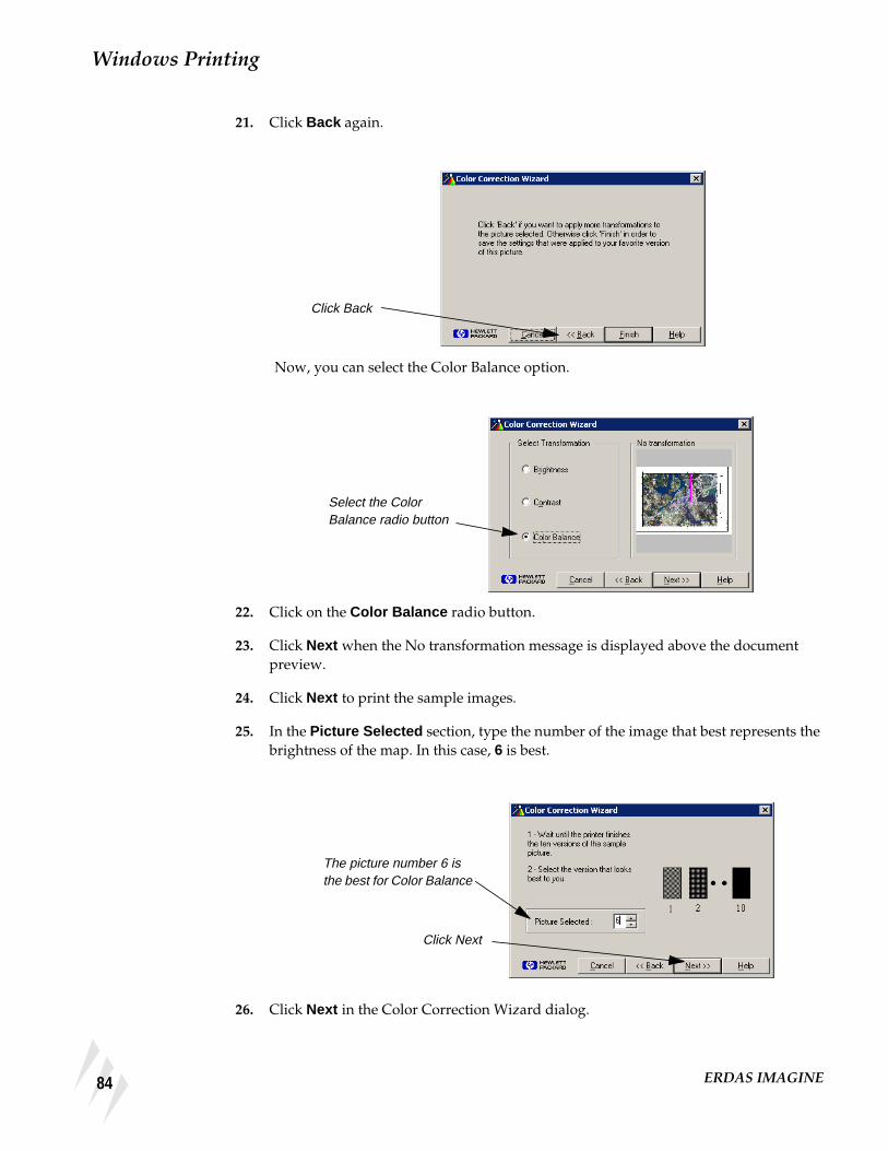
Windows Printing
21. Click Back again.
Now, you can select the Color Balance option.
22. Click on the Color Balance radio button.
23. Click Next when the No transformation message is displayed above the documentpreview.
24. Click Next to print the sample images.
25. In the Picture Selected section, type the number of the image that best represents thebrightness of the map. In this case, 6 is best.
26. Click Next in the Color Correction Wizard dialog.
Click Back
Select the ColorBalance radio button
The picture number 6 isthe best for Color Balance
Click Next
84 ERDAS IMAGINE

Scenarios
Now, you have defined all three elements of the Color Correction Wizard: Brightness ,Contrast , and Color Balance .
27. Click on Finish in the Color Correction Wizard.
A dialog opens advising you that the color calibration was a success.
28. Click on OK in the Color Calibration Successful dialog.
You are returned to the Properties dialog. If you have the User Defined ColorCorrection selected, it uses your color calibration.
29. Click the Advanced tab in the Properties dialog.
85Installation Guide

Windows Printing
30. Click OK in the Properties dialog.
Return to the Print Map Composition Dialog
1. Click the Page Setup tab in the Print Map Composition dialog.
Your Print Map Composition dialog Page Setup tab should look like this.
2. Click the Options tab of the Print Map Composition dialog.
The Options tab looks like this:
Click the PageSetup tab
86 ERDAS IMAGINE

Scenarios
3. Click the Preview tab of the Print Map Composition dialog.
Finally, your Preview tab should look like this:
4. Click OK to print your map.
Pre-Rasterize Another scenario involves the Pre-Rasterize option. If you want to print large mapsor print to higher resolution print devices, it is probably necessary to utilize the Pre-Rasterize option in ERDAS IMAGINE in conjunction with an HPRTL driver. Thereare similar languages that can be utilized with plotters sold by other printermanufacturers.
Click theOptions tab
Click the Previewtab
87Installation Guide

Windows Printing
This map is large. It is 52” x 68”. It is printed at 600 dpi, and would easily exceed thesystem limits for successful printing. This map cannot print without pre-rasterizationunless the Printer Data Transfer Compression preference is set to high. Even then, theraster data that is printed appears highly degraded as no higher than a compressionfactor of low or 2 can be effectively used with this data. Consequently, the Pre-Rasterize option is used in order to print successfully.
The 52” height of the map corresponds with the 54” width of the paper for the HP 3500.There are effectively 31200 pixels, or dots, available for plotting at 600 dpi. The imagein the map frame is 37000 pixels high. This map would be best processed with thePrinter Data Transfer Compression preference set to none , but that would alsoquadruple the amount of data that is sent to the plotter. So, you are going to use thedefault Printer Data Transfer Compression preference low . This generally providesacceptable results.
Preparation
ERDAS IMAGINE must be running.
You must have a map composition displayed.
NOTE: The map composition displayed in this scenario is not supplied with the examples data.You may want to use the following steps to print the map composition you created in"CHAPTER 3: Map Composer" in the ERDAS IMAGINE Tour Guides.
1. In the Map Composer dialog, click the Print icon.
88 ERDAS IMAGINE

Scenarios
This brings up the Print Map Composition dialog. The Print Map Composition dialogopens on the Printer tab. In this tab, you can select a printer you have configured.
For information about how to configure a printer, see the most recent ERDAS IMAGINEInstallation Guide.
2. In the Print Map Composition dialog, select the printer from the Print Destinationdropdown list.
Once you choose your printer, the Rasterize before printing option displays.
3. Click the Rasterize before printing checkbox.
4. Click on the Change printer configuration button.
Select the printer fromthe dropdown list
Click to select the Rasterizebefore printing option
Click the Change printerconfiguration button
89Installation Guide

Windows Printing
The Properties dialog opens. It has the name of the printer you selected as the PrintDestination .
5. In the Application page size section of the Page Size tab, set the paper size to 54” x 72”.
6. Click on the Layout View tab of the Properties dialog.
7. Look at the Layout View to verify the parameters.
8. Click on the Options tab of the Properties dialog.
Set the page size here
Click the Layout View tab
90 ERDAS IMAGINE

Scenarios
The Options display.
9. Set the Paper type and Quality .
The Quality should be set to Photo or Best , which is 600 dpi if the highest quality isdesired.
10. Click on the Manual color radio button in the Options tab.
11. Click on the Color control button to check the Color Control settings.
The Color Control dialog opens.
12. Set the Printed color control to User defined color correction .
Set the Paper typeand Quality
Select Manualcolor
Click the Colorcontrol button
Select the Userdefined colorcorrection radiobutton
91Installation Guide

Windows Printing
This should still be set to the same values used in the previous exercise, “No Pre-Rasterize”. If you did not perform the previous exercise, the procedure for setting theUser defined color correction is fully described there, on page 79.
13. Click on the Advanced tab.
14. Click the In Printer radio button.
In the previous exercise, the In Computer radio button was set so that printing couldbe done using the no pre-rasterize method in IMAGINE.
15. Click OK in the Advanced tab.
The Page Setup tab of the Print Map Composition dialog displays.
92 ERDAS IMAGINE

Scenarios
16. Verify the parameters on the Page Setup tab.
17. Click the Options tab.
18. Verify the parameters on the Options tab.
19. Click on the Preview tab.
Click the Options tab
93Installation Guide

Windows Printing
20. Examine the Print Preview.
21. Click OK in the Print Map Composition dialog to print.
Click the Preview tab
94 ERDAS IMAGINE

CHAPTER 9Configuring IMAGINE VirtualGIS for Windows
StereoConfiguration forWindows Systems
Only Stereo-In-A-Window is supported for Windows 95, Windows 98, and WindowsNT. A stereo graphics emitter, an emitter cable, liquid crystal glasses, and a stereo-capable graphics card are required to use the Stereo-In-A-Window option.
Most stereo-capable graphics cards provide a control panel for enabling and disablingstereo display (see your graphics card’s instructions). The card must be stereo-enabledbefore starting IMAGINE VirtualGIS.
Contact StereoGraphics (http://www.StereoGraphics.com) for the specific cableneeded to work with your system and graphics card.
ERDAS IMAGINEPreference Settings
Several ERDAS IMAGINE preferences can be modified to improve the performance ofIMAGINE VirtualGIS. These changes may affect other applications running within theERDAS IMAGINE environment.
User Interface and Session
The Dialogs Follow Parent preference should be off. When entering or exiting stereomodes in IMAGINE VirtualGIS, this preference may cause the supporting dialogs tobecome inaccessible.
Memory
The Directory for the External Memory File preference needs to have a directory ona local file system with greater than 20 MB available. IMAGINE VirtualGIS creates afile in the specified directory to use before any system memory is consumed. Thisimproves the performance when rendering large Virtual Worlds in IMAGINEVirtualGIS.
The Total Size of External Memory in Megabytes preference should be set to greaterthan 20 MB.
ERDAS IMAGINE Image Files (Native)
The Memory Map File Size Limit and Memory Map Segment Height preferencesshould both be set to 0.000. This disables memory mapping. Some Virtual Worlds builtin the Virtual World Editor could be greater than the defaults displayed.
95Installation Guide

Configuring IMAGINE VirtualGIS for Windows
96 ERDAS IMAGINE

Section TwoUNIX Installation andConfiguration
97Installation Guide

Section Two UNIX Installation and Configuration
98 ERDAS IMAGINE

Preface to UNIX Installation
About This Manual The ERDAS IMAGINE Installation Guide takes you step-by-step through the installationof ERDAS IMAGINE® V8.4 software. You should read "CHAPTER 10: Preparation forInstallation under UNIX"before you begin the installation process to verify that yoursystem is properly set up for the software.
Standard Installation vs. Advanced Installation
There are two ways to install the software, depending on your system setup.
• If your workstation is a stand-alone system or a system on a network with a localCD-ROM, read"CHAPTER 11: Standard CD-ROM Installation".
• If your workstation is connected to a network and has a remote CD-ROM, followthe instructions in "CHAPTER 12: Advanced CD-ROM Installation".
When you perform a Standard installation, you must install the software from the rootaccount. If you do not want to install the software as root, then you must perform anAdvanced installation.
NOTE: ERDAS IMAGINE V8.4 does not support installation from tape drives.
Security Codewords Request Form
The ERDAS IMAGINE software security system uses security codewords to protectthe software against unauthorized use. You need to fill out the Security CodewordsRequest Form located in the Important Information material and mail or fax it toERDAS Codeword Support to receive your security codewords. The SecurityCodewords Request form can also be obtained via the ERDAS web site(www.erdas.com).
ERDAS IMAGINE V8.3 users: If you have ERDAS IMAGINE V8.3, you need toreceive new codewords for ERDAS IMAGINE V8.4. The security broker for ERDASIMAGINE V8.4 recognizes the codewords used with ERDAS IMAGINE V8.3 and thenew ERDAS IMAGINE V8.4 codewords. If you are working with both versions ofERDAS IMAGINE, use the security broker from V8.4. During installation, enter yourV8.4 codewords first and then enter your V8.3 codewords.
99Installation Guide

Preface to UNIX Installation
Documentation The ERDAS IMAGINE Installation Guide is part of a whole suite of printed and on-linedocumentation that you receive with ERDAS IMAGINE software.
Printed Documentation
Following is a listing of printed documentation that is available with ERDASIMAGINE software:
• ERDAS Field Guide™
• ERDAS IMAGINE Installation Guide
• ERDAS IMAGINE Tour Guides™
• ERDAS IMAGINE V8.4 Release Notes and Important Information
On-Line Documentation
Following is a listing of on-line manuals that can be found in the On-Line Help inERDAS IMAGINE software. These may have been delivered in printed form or asdigital .pdf files:
• Introduction to ERDAS IMAGINE On-Line Manual
• Annotation On-Line Manual
• AOI On-Line Manual
• Classification On-Line Manual
• C_Tools On-Line Manual
• DLL On-Line Manual
• EML On-Line Manual
• Expert Classifier On-Line Manual
• Graphical Models On-Line Manual
• HyperSpectral On-Line Manual
• IMAGINE Command and Function Syntax On-Line Manual
• IMAGINE Interface On-Line Manual
• Image Catalog On-Line Manual
• Image Interpreter On-Line Manual
• Import/Export On-Line Manual
• Map Composer On-Line Manual
• OrthoBASE On-Line Manual
100 ERDAS IMAGINE

Documentation
• Radar Mapping Suite On-Line Manual
• Rectification On-Line Manual
• Session On-Line Manual
• SML On-Line Manual
• Spatial Modeler On-Line Manual
• Tools and Utilities On-Line Manual
• Vector On-Line Manual
• Viewer On-Line Manual
• Viewer Raster Tools On-Line Manual
• Virtuality On-Line Manual
Documentation Functions
The following chart depicts the different types of information you can extract fromERDAS IMAGINE documentation.
If you want to... Read...
Install ERDAS IMAGINE ERDAS IMAGINE V8.4 Release Notes, thenERDAS IMAGINE Installation Guide
Set up hardware for use with ERDASIMAGINE
ERDAS IMAGINE Installation Guide
Learn about new features in the latest release ERDAS IMAGINE V8.4 Release Notes
Learn to use ERDAS IMAGINE ERDAS IMAGINE Tour Guides
Learn about GIS and image processing theory ERDAS Field Guide
See what a particular dialog does ERDAS IMAGINE On-Line Help
Get quick information for a button or function ERDAS IMAGINE On-Line Help or Status BarHelp
Learn how to most effectively use the On-LineHelp system
ERDAS IMAGINE On-Line Help
Learn more about the Image Interpreterfunctions
ERDAS IMAGINE Tour Guides
Use the Spatial Modeler Language to writemodels
On-Line Spatial Modeler Language manual
Customize the ERDAS IMAGINE graphicaluser interface
On-Line ERDAS Macro Language (EML)manual
Write custom application programs withinIMAGINE
On-Line IMAGINE developers’ Toolkit manual
101Installation Guide

Preface to UNIX Installation
Conventions Used inThis Book
In ERDAS IMAGINE, the names of menus, menu options, buttons, and othercomponents of the interface are shown in bold type. For example:
“In the Select Layer To Add dialog, select the Fit to Frame option.”
<words>
When you see words enclosed in < > substitute the proper information for these words.For example, when you see <system arch> in this document, replace it with the systemarchitecture for your workstation (e.g., sun4).
Prompts
Words that appear in the font style above represent program prompts that displays onthe screen.
Commands, Entries
Words that appear in the font style above are used to show commands that you needto enter and examples of data that you may enter as a response to a program prompt.A word enclosed in brackets [] at the end of a prompt is the default answer for thatprompt. Press the Return key to accept the default answer.
# Root Prompt
The # symbol is used to represent the prompt on your system when you login as root.
Paragraphs
The following paragraphs are used throughout the ERDAS IMAGINE documentation:
These paragraphs contain strong warnings or important tips.
These paragraphs direct you to the ERDAS IMAGINE software function thataccomplishes the described task.
These paragraphs lead you to other chapters in the ERDAS IMAGINE Installation Guideor other manuals for additional information.
102 ERDAS IMAGINE

Obsolete
Obsolete Device drivers and configuration instructions for the following hardware are no longerprovided with standard IMAGINE releases.
• CalComp 68000 Electrostatic plotter
• IRIS Color Inkjet printer
• Kodak XL7700 printer
• Tektronix Inkjet printer
• Versatec ServeWare converter
103Installation Guide

Preface to UNIX Installation
104 ERDAS IMAGINE

CHAPTER 10Preparation for Installation under UNIX
Description This section briefly explains the steps for preparing your UNIX workstation forinstalling ERDAS IMAGINE V8.4 software.
Operator Expertise
The system setup and the software installation should be performed by a systemmanager who is familiar with the UNIX workstation and its documentation.
If you are setting up a new workstation on which user accounts have not yet beenassigned, then you must set up at least one user account that may access ERDASIMAGINE. Please refer to the appropriate manuals as well as to these instructions.
Security Codeword Request Form
A Security Codewords Request Form is located in the Important Information material.You must complete this form and send it to ERDAS Codeword Support to receive yoursecurity codewords. Security codewords are explained in the ERDAS SoftwareSecurity section of this chapter.
V8.3 Users
If you have enough disk space, it is recommended that you keep ERDAS IMAGINEV8.3 on your system until you feel comfortable with running ERDAS IMAGINE V8.4.
The security broker for ERDAS IMAGINE V8.4 recognizes the codewords used withERDAS IMAGINE V8.3 and the new ERDAS IMAGINE V8.4 codewords. If you areworking with both versions of ERDAS IMAGINE, use the security broker from V8.4.During installation, enter your V8.4 codewords first and then enter your V8.3 codewords.
See the Running ERDAS IMAGINE V8.3 and 8.4 section in "CHAPTER 11: StandardCD-ROM Installation" or "CHAPTER 12: Advanced CD-ROM Installation" of thismanual for instructions to continue running ERDAS IMAGINE V8.3.
105Installation Guide

Preparation for Installation under UNIX
Requirements Before you begin installing ERDAS IMAGINE software, you need to know thefollowing:
• if your workstation is connected to a network
• whether or not you want to install the software from the root account
• the name of the CD-ROM mount point
• where you want to install the ERDAS IMAGINE software security program
If you install everything onto the same workstation, then the installation process isrelatively easy.
For more information about ERDAS IMAGINE software security, see the SoftwareSecurity section on "CHAPTER 13: Security System"
106 ERDAS IMAGINE

Requirements
Hardware
Table 10-1 Minimum Requirements for ERDAS IMAGINE V8.4
a This is the hard disk space requirement for installation of all modules and example data.
b When you are using a 24-bit display board you should have more memory—we recommend 96MB (128for the Compaq AlphaStation and the IBM RS/6000). The first time you bring up a Viewer, the Viewercreates a backing store. A backing store allows the image in the Viewer to be refreshed quickly. However,with a 24-bit display ERDAS IMAGINE uses about 4 MB of memory for each backing store. This is whyextra memory is required. If you do not have extra memory, ERDAS IMAGINE runs slower. With an 8-bitdisplay, ERDAS IMAGINE uses only 1 MB of memory for each backing store.
cYou need more swap space (384 MB to 512 MB) for full scenes with ERDAS IMAGINE IFSAR DEM.
dIt is necessary to apply patch PHSS_15853 to HP-UX machines to correct a problem in the Xserver causingcolor-striping and other visual artifacts.
NOTE: These requirements are subject to change. Please see the Release Notes in the ImportantInformation material for corrections or visit our web site at http://www.erdas.com for the latestspecifications.
System Disk
Space aSwapSpace
Memory b WindowSystem
OperatingSystem
Compaq AlphaStation 575 MB 300 MB 96 MB (128 MB whenusing a 24-bit display)
OSF/Motif Compaq Tru64 UNIX(4.0F)
HP 9000 family, series700 and 800
600 MB 250 MBc 64 MB (96 MB whenusing a 24-bit display)
X11/Motif d HP-UX 11.00
IBM RS/6000 650 MB 250 MB 96 MB (128 MB whenusing a 24-bit display)
AIX Windows AIV 4.3.2
Silicon Graphics R4000and up
600 MB 200 MB 64 MB (96 MB whenusing a 24-bit display)
X11/Motif IRIX 6.5
Sun SPARCstation 550 MB 200 MB 64 MB (96 MB whenusing a 24-bit display)
Open Windows Solaris 2.6, and 2.7
107Installation Guide

Preparation for Installation under UNIX
Swap Space Use the table on page 107 to determine how much free swap space you should have inorder to run ERDAS IMAGINE. Use the commands below to determine how muchswap space you currently have on your workstation.
Compaq AlphaStation
/sbin/swapon -s
If it is less than the minimum requirement, you should increase the swap space.
In order to make the best use of swap space when running IMAGINE, it isrecommended that Compaq AlphaStations be configured to use deferred swap spacemode. For information on the swap space modes under Compaq Tru64 UNIX (4.0F),type the following in a UNIX shell:
# man swapon
In order to change a system from immediate mode to deferred mode, you must log inas root, rename the file /sbin/swapdefault , and then reboot:
# cd /sbin# mv swapdefault swapdefault.bak# reboot
HP 9000
Log in to the root account and use the following command to determine how muchswap space you have:
/etc/swapinfo
If it is less than the minimum requirement, you should increase the swap space.
IBM RS/6000
Log in as root and use the following command to determine how much swap spaceyou have:
/usr/sbin/lsps -s
If it is less than the minimum requirement, you should increase the swap space.
Silicon Graphics
Use the following command to determine how much swap space you have:
/sbin/swap -s
This command shows you the configured, reserved, used, free, and available swapspace. The used plus the available swap space is the amount that is on your system. Ifthis sum is less than the minimum requirement, you should increase the swap space.
108 ERDAS IMAGINE

User Accounts
Sun SPARCstation
Sun Solaris 2.6
/usr/sbin/swap -s
This command shows you the configured, reserved, used, free, and available swapspace. The used swap space plus the available swap space is the amount that is on yoursystem. If this sum is less than the minimum requirement, you should increase theswap space.
User Accounts This section describes steps for setting up user accounts that are necessary or helpfulwhen running ERDAS IMAGINE software. Refer to the system and networkadministration manual for your workstation for more detailed information aboutsetting up user accounts.
Using the documentation that accompanies the UNIX system, you (the systemmanager) must create user accounts. Every user of the workstation has a user nameand a password for logging into the system. The user names and passwords areusually unique for each user.
Types of Access
You may allow the user of each account to access the files in certain directories in theseways:
• Read to read or copy the file, but not change the original copy.
• Write to change the file.
• Execute to run an executable file.
ERDAS IMAGINE users must have read and write access to files in directory /tmp.
ERDAS IMAGINE on Root Menu
It might be helpful to add an option for running ERDAS IMAGINE software from theroot menu (the menu that displays when the user clicks on the background). You cando this by modifying one of the following files in your home directory:
• .mwmrc file if you are using the Motif window manager
• .openwin-menu file if you are using the OpenLook window manager
Refer to your window manager manuals for instructions on modifying these files.
109Installation Guide

Preparation for Installation under UNIX
Setting Up YourWindowEnvironment
Optionally, you can follow these instructions to configure your window environmentfor use with ERDAS IMAGINE.
Most users are running the Common Desktop Environment (CDE) window manager.All of the configuration options for the CDE window manager are controlled throughthe CDE Style Manager utility. If you are running the Motif or OpenLook windowmanager, you may want to make further additions to the .Xdefaults file in your homedirectory to customize ERDAS IMAGINE for your personal use.
OpenLook WindowManager (olwm)
The OpenLook window manager is configured using the following files in the user’shome directory. Change or add the lines listed below as desired.
Add the following lines to the .Xdefaults files:
OpenWindows.WindowColor:color of window framesOpenWindows.WorkspaceColor:color of workspace background
Add the following line to the Programs section of the .openwin-menu file:
"Imagine... " "<IMAGINE_HOME>/bin/imagine"
<IMAGINE_HOME> refers to the directory where IMAGINE software resides (e.g.,/usr/imagine/840).
Motif Window Manager(mwm)
The Motif window manager is configured using the following files in the user’s homedirectory. Change or add the lines listed below as desired.
NOTE: This information is also applicable to AIX Windows.
Add the following lines to the .Xdefaults file:
Mwm.background: color of workspace backgroundMwm.foreground: color of inactive window frameMwm.activeForeground: color of active window frameMwm*keyboardFocusPolicy:pointerMwm*clientAutoPlace: false
Add the following line to the Programs section of the .mwmrc file:
"Imagine..." f.exec"<IMAGINE_HOME>/bin/imagine"
<IMAGINE_HOME> refers to the directory where ERDAS IMAGINE software resides(e.g., /usr/imagine/840).
HP VUE
If you want to configure HP VUE to function more like Motif, make one or more of thefollowing changes:
• Add the following line to the .vueprofile file:
source $HOME/.cshrc
110 ERDAS IMAGINE

Setting Up Your Window Environment
• Add the following line to the .cshrc file:
setenv XENVIRONMENT $HOME/.Xdefaults
• Add the following line to the .Xdefaults file:
Vuewm*clientAutoPlace: False
Silicon Graphics
If you wish, you may use the Motif window manager in lieu of the Silicon Graphics4Dwm window manager. Motif Window Manager is NOT provided with IRIX; youmust acquire and install this software separately.
If you are using 4Dwm and you don't want to interactively place your icons, add thefollowing line to your .Xdefaults file in your home directory.
*interactivePlacement: false
If you want to start the Motif window manager (mwm) instead of the 4Dwm, place thefollowing set of lines in the .xsession file in your home directory.
# /usr/bin/X11/xterm &# exec /usr/bin/X11/mwm (as the last line of the file)
You must remove the .xsession file before you can use the Silicon Graphics windowmanager (4Dwm).
Perform the following steps to prepare IRIX for use with ERDAS IMAGINE.
1. Run the following program to configure parameters for your system:
# /usr/sbin/systune -i
This program comes with IRIX.
2. Enter the following command at the systune prompt:
systune-> resource
111Installation Guide

Preparation for Installation under UNIX
3. Messages similar to the ones below displays:
rlimit_rss_max = 536870912 (0x20000000)rlimit_rss_cur = 27787264 (0x1a80000)rlimit_vmem_max = 536870912 (0x20000000)rlimit_vmem_cur = 536870912 (0x20000000)rlimit_nofile_max = 2500 (0x9c4)rlimit_nofile_cur = 100 (0x64)rlimit_core_max = 2147483647 (0x7fffffff)rlimit_core_cur = 2147483647 (0x7fffffff)rlimit_stack_max = 536870912 (0x20000000)rlimit_stack_cur = 67108864 (0x4000000)rlimit_data_max = 536870912 (0x20000000)rlimit_data_cur = 536870912 (0x20000000)rlimit_fsize_max = 2147483647 (0x7fffffff)rlimit_fsize_cur = 2147483647 (0x7fffffff)rlimit_cpu_max = 2147483647 (0x7fffffff)rlimit_cpu_cur = 2147483647 (0x7fffffff)
Make sure that the resource rlimit_nofile_cur is set to 200.
4. ERDAS IMAGINE may work with less than 200, however, we are not sure where thebreakpoint is located. If the resource is not 200, use the following command to set it:
systune-> rlimit_nofile_cur 200
5. The following message displays:
rlimit_nofile_cur = 100 (0x64)
6. Do you really want to change rlimit_nofile_cur to 200 (0xc8)? (y/n) Y
Y = The rlimit_nofile_cur is changed to 200.
N = The rlimit_nofile_cur is not changed.
Enter Y to change the limit.
7. Reboot your system using the following command:
# /etc/reboot
NOTE: All of the above steps require root authority.
HP 9000
Perform the following steps to prepare HP-UX for use with ERDAS IMAGINE.
1. Run the System Administration Manager to configure parameters for your system:
# /usr/sbin/sam
112 ERDAS IMAGINE

Setting Up Your Window Environment
2. Select Kernel Configuration from the SAM Areas.
3. Select Configurable Parameters from the next list of areas.
4. Find the parameters named maxfiles and maxfiles_lim. The default values are 60 and 1024respectively. The maxfiles parameter needs to be at least 200. The maxfiles parametercannot be greater than maxfiles_lim, so if the maxfiles_lim parameter is less than 200, italso needs to be changed.
5. For IMAGINE IFSAR DEM, change the maxdsiz parameter to at least 256 MB. Thedefault is 64 MB.
6. To change the value of a parameter, double-click on it (if you are running SAM underX Windows), or select the parameter and perform Actions -> Modify ConfigurableParameter from the main menu. Then enter the new value in the Formula/Value fieldand select OK. For maxdsiz, enter the value 256 MB, which is 0X10000000.
7. Once the parameters are properly set you must apply them. To do so perform Actions-> Process New Kernel from the main menu. The following message appears:
Are you sure you want to process your kernel modifications now?A new kernel may need to be compiled and moved into place, andyour system rebooted, to make these kernel changes take effect.
8. Select Yes. Processing the new kernel may take a few minutes. Once it is doneprocessing, another dialog appears:
The new kernel you have just created must be moved into placeprior to shutting down or rebooting the system.
9. Make sure that Move Kernel Into Place and Shutdown/Reboot System Now isselected, and that Overwrite /stand/system is checked. Then select OK. A final promptappears:
The newly created configuration file is copied to /stand/system.Any comments in that file are lost because SAM cannot preservethem.
10. Selecting OK causes the system to reboot with the new parameters.
NOTE: All of the above steps require root authority.
IBM RS/6000
ERDAS IMAGINE requires the asynchronous I/O device. To make the deviceavailable, follow these steps:
113Installation Guide

Preparation for Installation under UNIX
1. Run the command:
# /usr/sbin/chdev -l aio0 -a autoconfig=’available’
2. Reboot the system using the following command:
# /usr/sbin/reboot
NOTE: Both of the above steps require root authority.
ERDAS SoftwareSecurity
This section gives you an overview of the ERDAS IMAGINE software security system,so that while you are installing ERDAS IMAGINE you have a better understanding ofthe process.
ERDAS IMAGINE software security is based on the concept of a license broker, whichis a program that is always running on at least one workstation on the network. Thisprogram is named erdmaster . It secures all copies of ERDAS IMAGINE software thatoperate on the network.
The license broker workstation is the machine on which the ERDAS IMAGINE securityprogram, erdmaster , operates. You are installing security codewords given to you byERDAS onto this workstation. These codewords protect the software againstunauthorized use and determine the following:
• which modules you can use
• the number of users
• when, or if, the modules expire
All ERDAS IMAGINE programs communicate with erdmaster via sockets, which areautomatically provided on all ERDAS IMAGINE-supported workstations. Socketsprovide network communications between programs on workstations within thenetwork.
You need to determine on which workstation the ERDAS IMAGINE security program,erdmaster , resides before you begin installing ERDAS IMAGINE software. If youinstall the security program on the same workstation where you install the software, thenthe installation process is easier.
Refer to "CHAPTER 13: Security System"for more detailed information about theERDAS IMAGINE software security system.
InstallationInstructions
There are two different sets of instructions for installing ERDAS IMAGINE:
• standard installation
• advanced installation
NOTE: The standard installation process is easier than the advanced installation process.
114 ERDAS IMAGINE

Installation Instructions
Standard Installation You should follow the instructions in"CHAPTER 11: Standard CD-ROM Installation"if:
• you are installing the software from the root account.
• you are installing the software on a stand-alone system (one workstation) that isnot connected to a network or on a system that is connected to a network with alocal CD-ROM drive.
• you are installing the security program, erdmaster, on this system. If you do notwant to install erdmaster on this system, you need to follow the instructions in"CHAPTER 12: Advanced CD-ROM Installation".
Advanced Installation You must follow the instructions in "CHAPTER 12: Advanced CD-ROM Installation"if:
• you are not installing the software from the root account.
• you are installing the software on a system that is connected to a network with aremote CD-ROM.
• when you do not install the security program, erdmaster, on the system where youare installing ERDAS IMAGINE software.
Installing ERDAS IMAGINEon this workstation
Installing erdmaster onthis workstation
Local CD-ROM
Stand-Alone System
System on a Network
115Installation Guide

Preparation for Installation under UNIX
Security Codewords The ERDAS IMAGINE software security system uses security codewords to protectthe software against unauthorized use. ERDAS IMAGINE software can be installedbefore you request the security codewords. However, these codewords must beinstalled in order for you to access the ERDAS IMAGINE software modules. To receiveyour codewords, you need to completely fill in the Security Codeword Request Formlocated in the Important Information material, then fax, e-mail, or mail it to ERDASCodeword Support. You can also access and complete the Security Codeword RequestForm via the ERDAS web site (www.erdas.com).
Please allow ERDAS up to 24 hours for processing your security codewords. Thecodewords can be sent to you by fax, mail, or e-mail. No codewords can be issued byphone.
Please read the Security Codeword Policy and fill out the Security Codewords RequestForm to obtain your codewords. Both of these items are located in the ImportantInformation material.
Please submit a separate Security Codewords Request Form for each host for which youare requesting codewords.
ERDAS IMAGINE V8.3 users: If you have IMAGINE V8.3 you need to receive newcodewords for IMAGINE V8.4. The security broker for IMAGINE V8.4 recognizes thecodewords used with IMAGINE V8.3 and the new IMAGINE V8.4 codewords. If you areworking with both versions of IMAGINE, use the security broker from V8.4. Duringinstallation, enter your V8.4 codewords first and then enter your V8.3 codewords.
Installing ERDAS IMAGINE onthis workstation
Installing erdmaster onthis workstation
Remote CD-ROM
System on a Network
116 ERDAS IMAGINE

Generate System ID
Generate System ID ERDAS Codeword Support must have your system ID in order to generate yoursecurity codewords. Your system ID is automatically displayed during the installationprocess. If for some reason you need to request your security codewords before youinstall ERDAS IMAGINE, you should follow the instructions below. These instructionsshow you how to generate your system ID before you install ERDAS IMAGINE.
See the "Security Codewords" section in "CHAPTER 11: Standard CD-ROMInstallation" or "CHAPTER 12: Advanced CD-ROM Installation" for information oninstalling your codewords.
Submitting an incorrect system ID on your request form may subject you to a charge fora CPU change (see the Security Codeword Policy included in your Important Informationmaterial). We strongly urge you to use the system ID generated during the installationprocess or the <IMAGINE_HOME>/install/showsysid command we provide after theinstallation for your platform. ERDAS offers no additional support for the instructionsbelow.
117Installation Guide

Preparation for Installation under UNIX
Showsysid Instructions If you have access to the ERDAS IMAGINE CD-ROM, you can use the utilityshowsysid to generate your system ID number. Follow these steps:
1. Mount the CD-ROM using the directions in "CHAPTER 11: Standard CD-ROMInstallation" or"CHAPTER 12: Advanced CD-ROM Installation".
2. Determine your system architecture type by consulting the list below:
• decosf for Compaq AlphaStation workstations
• hp700 for HP 9000 workstations
• rs6000 for IBM RS/6000 workstations
• sgi for Silicon Graphics workstations
• sun4sol for Sun SPARCstations using Solaris 2.6 or 2.7
3. Run the following command:
# <cd Mount Point>/contents/bin/<ARCH>/showsysid
Where <cd Mount Point> represents the mount point of the CD-ROM file system and<ARCH> represents the architecture type determined in step 2.
Non-showsysidInstructions
Depending on the type of your platform, perform the following steps to generate yoursystem ID before you begin the installation process. Please follow these instructionscarefully.
<IMAGINE_HOME> refers to the directory where ERDAS IMAGINE softwareresides.
NOTE: This ID number is automatically generated during the installation process.
Compaq AlphaStation
Log in as root and run the following command. Use the 12 digits that follow thestring "_hardware address" for your system ID (ignore the dashes that appear betweenthe digits):
/usr/sbin/uerf -R -r 300 | grep "_hardware address"
After the installation process, you may use the<IMAGINE_HOME>/install/showsysid command to generate your system ID.
These instructions apply only to workstations that have only one Ethernet address.Other configurations must use the system ID generated from the installation process.
HP 9000
Log in to the root account and then run the following command, using the last twelvedigits under the column labeled Station Address for your system ID:
/etc/lanscan
After the installation process, you may use the<IMAGINE_HOME>/install/showsysid command to generate your system ID.
118 ERDAS IMAGINE

Generate System ID
These instructions apply only to workstations that have only one Ethernet address.Other configurations must use the system ID generated from the installation process.
IBM RS/6000
Use the twelve digits returned from the following command for your system ID:
/usr/bin/uname -m
When you get the system ID, convert the first two and last two characters to fd . Thisis the number that you report to ERDAS to get your security codewords. After theinstallation process, you may use the <IMAGINE_HOME>/install/showsysidcommand.
Silicon Graphics
Use the first eight digits from the following command for your system ID:
/etc/sysinfo
After the installation process, you may use the<IMAGINE_HOME>/install/showsysid command to generate your system ID.
Sun SPARCstation
Sun Solaris 2.6 or 2.7
Run the following command and use these eight digits for the hostid as your systemID:
/usr/ucb/hostid
After the installation process, you may use the<IMAGINE_HOME>/install/showsysid command to generate your system ID.
119Installation Guide

Preparation for Installation under UNIX
120 ERDAS IMAGINE

CHAPTER 11Standard CD-ROM Installation
Standard vs.AdvancedInstallation
This section contains the steps for installing ERDAS IMAGINE software on a UNIXworkstation.
Standard Installation
If you are installing the software on a stand-alone system (one workstation), or on asystem on a network with a local CD-ROM drive, then follow the instructions in thischapter. When you follow the Standard CD-ROM Installation instructions, you needto have access to the root account and install the security program, erdmaster, on thesame workstation where you are installing ERDAS IMAGINE software. If theconfiguration is other than this, or if you have a remote CD-ROM drive, then you needto follow the instructions in "CHAPTER 12: Advanced CD-ROM Installation".
Advanced Installation
If you are installing the software on a workstation that is connected to a network andyou are using a remote CD-ROM drive, you must follow the instructions in"CHAPTER 12: Advanced CD-ROM Installation". You must also follow theseinstructions if you are installing the security program, erdmaster, on a differentworkstation from where you are installing ERDAS IMAGINE software, or if you arenot installing ERDAS IMAGINE from the root account.
The proper user accounts must already be configured. You must have at least one useraccount that can access ERDAS IMAGINE software. See "CHAPTER 10: Preparationfor Installation under UNIX"for information on setting up user accounts.
Installing ERDAS IMAGINEon this workstation
Installing erdmaster onthis workstation
Local CD-ROM
Stand-Alone System
System on a Network
121Installation Guide

Standard CD-ROM Installation
System Architecture The phrase <system architecture> is used in examples throughout this manual. Thisphrase is replaced by the actual name of your system architecture in the installationprompts and diagnostic messages. This is a list of all of the system architectures thatare supported by ERDAS IMAGINE:
• decosf for Compaq AlphaStation workstations
• hp700 for HP 9000 workstations
• rs6000 for IBM RS/6000 workstations
• sgi for Silicon Graphics workstations
• sun4sol for Sun SPARCstations using Solaris 2.6 or 2.7
Setup forInstallation
A CD-ROM drive must be installed on your system, and the ERDAS IMAGINEinstallation CD must be inserted properly in the CD-ROM drive.
On each UNIX workstation, there is an account called the root account. To installERDAS IMAGINE software with the Standard Installation process, you must know thepassword (if any) to the root account, and gain access to the root account.
NOTE: If you do not want to install ERDAS IMAGINE software from the root account, youmust follow the instructions in"CHAPTER 12: Advanced CD-ROM Installation"
1. Log in to the root account.
login: root
2. Check to see if erdmaster is running: ps -aux | grep erdmaster
All Other Workstations
ps -ef | grep erdmaster
3. If erdmaster is running, kill it:
kill -9 <pid>
Mount the CD-ROM The mounting instructions are slightly different for each platform. Follow theinstructions below for the platform on which you are installing, then go to "Run InstallProgram" on page 126.
Compaq AlphaStation
4. Enter the following commands to be able to run the installation programs from a CD-ROM drive. If you do not already have a <mount point> directory, you must create it.Replace <device name> with the name of the CD-ROM device file for your system.
# mkdir <mount point>
# mount -r -t cdfs -o noversion,rrip <device name> <mount
122 ERDAS IMAGINE

Mount the CD-ROM
point>
# cd <mount point>
Example: # mkdir /cdrom# mount -r -t cdfs -o noversion,rrip /dev/rz4c /cdrom# cd /cdrom
Follow the instructions under "Run Install Program" on page 126.
HP 9000
4. Enter the following commands to be able to run the installation programs from a CD-ROM drive. If you do not already have a <mount point> directory, you must create it.Replace <device name> with the name of the CD-ROM device file for your system.
HPUX 11.00
# mkdir <mount point>
# mount -r -F cdfs <device name> <mount point>
# cd <mount point>
Example: # mkdir /cdrom# mount -r -F cdfs /dev/dsk/c1t2d0 /cdrom# cd /cdrom
Follow the instructions under "Run Install Program" on page 126.
IBM RS/6000
4. Enter the following commands to be able to run the installation programs from a CD-ROM drive. If you do not already have a <mount point> directory, you must create it.Replace <device name> with the name of the CD-ROM device file for your system.
# mkdir <mount point>
# mount -v cdrfs -p -r <device name> <mount point>
# cd <mount point>
Example: # mkdir /cdrom# mount -v cdrfs -p -r /dev/cd0 /cdrom# cd /cdrom
Follow the instructions under "Run Install Program" on page 126.
Silicon Graphics Some systems may have a CD daemon running to automatically mount a CD-ROMdrive when a CD is inserted. On Silicon Graphics, the daemon is mediad. If yoursystem is running a CD daemon, go to step 5.
123Installation Guide

Standard CD-ROM Installation
4. Enter the following commands to be able to run the installation programs from a CD-ROM drive. If you do not already have a <mount point> directory, you must create it.Replace <device name> with the name of the CD-ROM device file for your system.
NOTE: If the mediad daemon is running, the CD is mounted automatically. Omit this stepand proceed to step 5.
# mkdir <mount point>
# mount -o setx -t iso9660 <device name> <mount point>
# cd <mount point>
Example: # mkdir /cdrom# mount -o setx -t iso9660 /dev/scsi/sc1d6l0 /cdrom# cd /cdrom
5. If mediad is running on your system, enter the following command to change directoryto the mount point directory.
NOTE: The mount point directory may be different if your System Administrator has changedthe default.
# cd /CDROM
Follow the instructions under "Run Install Program" on page 126.
124 ERDAS IMAGINE

Mount the CD-ROM
Sun SPARCstation Some systems may have a CD daemon running to automatically mount a CD-ROMdrive when a CD is inserted. On Sun SPARCstations under Solaris 2.6 or 2.7, thedaemon is vold. If your system is running a CD daemon, go to step 5.
4. Enter the following commands to be able to run the installation programs from a CD-ROM drive. If you do not already have a <mount point> directory, you must create it.Replace <device name> with the name of the CD-ROM device file for your system.
NOTE: If the vold daemon is running, the CD is mounted automatically. Omit this step andproceed to step 5.
Sun Solaris 2.6 or 2.7
# mkdir <mount point>
# mount -r -F hsfs <device name> <mount point>
# cd <mount point>
Example: # mkdir /cdrom# mount -r -F hsfs /dev/sr0 /cdrom# cd /cdrom
5. If vold is running on your system, enter the following command to change directory tothe mount point directory.
NOTE: The mount point directory may be different if your System Administrator has changedthe default.
# cd /cdrom/imagine840_u
Go to step 1. on page 126.
125Installation Guide

Standard CD-ROM Installation
Run Install Program
1. Now that you have access to the installation programs from the CD, you are ready touse them to install the software. To install ERDAS IMAGINE software, enter thiscommand:
# ./install.cd
2. As the installation program begins, a welcome message is displayed:
Welcome to the IMAGINE installation script.
During the installation procedure, if you want to createa shell for your use, enter an exclamation point (!) inresponse to any prompt. On exit from the shell, the lastprompt displayed before the shell was created will be re-displayed for you to answer.
Also, if a prompt has a default response, this responsewill be displayed in brackets (e.g., [default value]).This default value can be selected simply by hittingRETURN.
Press RETURN to continue...
If you are prepared to continue with the installation, press Return. Otherwise, you maycancel the installation by pressing Control-C.
3. Please enter the mount point for the CDROM: [/cdrom]: /cdrom
The mount point must be the directory that was created in step 4. above, or thedirectory created automatically by the CD daemon. Press Return to accept the default.
4. The license agreement message appears:
Please read the license file located in:
cdrom/license.txt.
By proceeding with installation, you agree to be boundby the TERMS AND CONDITIONS set by this license.
5. Enter Y to continue or N to exit. Please enter the installation directory name:[/usr/imagine] /usr/imagine
126 ERDAS IMAGINE

Run Install Program
Enter the name of the directory where ERDAS IMAGINE software is installed, such as/usr/imagine. This directory is created if it does not already exist, then a subdirectoryis created within this directory with the ERDAS IMAGINE version number as its name(e.g., /usr/imagine/840). ERDAS IMAGINE is loaded into this subdirectory. Thisprevents you from overwriting a previous version of ERDAS IMAGINE (e.g., V8.3) onyour system.
While the directory is being created, the following message displays:
Created <install directory>/840
NOTE: Throughout the rest of this manual, <IMAGINE_HOME> refers to the location of thesubdirectory that was created (e.g., /usr/imagine/840). This is where ERDAS IMAGINEsoftware resides.
Selecting Modules Follow the instructions below to select the modules to install.
6. A screen displays similar to the one below, listing the modules that you may install.
If any modules have already been installed in the specified installation directory, an Xappears before the name of the module. An A indicates that the module is available forinstallation, and an I indicates that the module is not available on the media, but hasalready been installed in the specified directory.
Please wait...searching for installable modules in
directory /cdrom
Table 11-1 Installable Modules
data-
decosf-
gnrl-
hp700-
rs6000-
sgi-
sun4sol-
A A A A A A A 1. IMAGINE Essentials
A A A A A A 2. IMAGINE Vector
A A A A A A A 3. IMAGINE Advantage
A A A A A A A 4. IMAGINE Radar Interpreter
A A A A A A A 5. IMAGINE Professional
A A A A A A A 6. IMAGINE VirtualGIS
A A A A A 7. IMAGINE LZW
A A A A A A A 8. IMAGINE StereoSAR DEM
A A A A A A A 9. IMAGINE IFSAR DEM
A A A A A A A 10. IMAGINE OrthoRadar
127Installation Guide

Standard CD-ROM Installation
The above modules may be installed. An X in the key at the left indicates that theparticular fileset of the given module has already been installed in the selectedinstallation directory and that same fileset is also available on the installation medium.An A in the key indicates that the fileset is available on the installation medium, buthas not yet been installed.Finally, an I in the key indicates that the fileset is notavailable on the current installation medium, but has been installed in the installationdirectory (/usr/imagine).
Select the module(s) you wish to install by specifying the product's number separatedby spaces (e.g., 1 3 4): [2 5]
NOTE: You should select only the modules for which you have a license. The security programprevents you from running unlicensed modules. Installing unlicensed modules needlesslyconsumes disk space.
NOTE: Selecting the IMAGINE Install ALL Modules does not install the IMAGINERemote Services module because its components are included with IMAGINE Essentials. Ifyou wish to install it in addition to all of the others, you must specify both the IMAGINE InstallALL modules product number and the IMAGINE Remote Services product number.
Essentials Module
The IMAGINE Essentials module is required to run any ERDAS IMAGINE module.
Advantage Module
When you load the IMAGINE Advantage module, the IMAGINE Essentials module isalso automatically loaded. Both of these filesets are required to run the IMAGINEAdvantage module.
Professional Module
When you load the IMAGINE Professional module, the IMAGINE Essentials,IMAGINE Advantage, and IMAGINE Radar modules are also automatically loaded.All of these filesets are required for, or included in, the IMAGINE Professional module.
7. After you select the modules to load, a screen similar to the one below displays:
A A A A A A 11. IMAGINE Remote Services
12. IMAGINE Install ALL Modules
13. ABORT INSTALLATION
Table 11-1 Installable Modules (Continued)
data-
decosf-
gnrl-
hp700-
rs6000-
sgi-
sun4sol-
128 ERDAS IMAGINE

Run Install Program
The following modules were selected...
IMAGINE EssentialsIMAGINE VectorIMAGINE AdvantageIMAGINE Radar InterpreterIMAGINE ProfessionalIMAGINE Remote Services
*** Be aware that you will only be able to use those ****** modules for which you have obtained security ****** codewords. Installing unsecured modules will only ****** consume disk space unnecessarily ***
Are these the modules you want to install? [Y]
Y = These are the modules to be installed. Go to step 8.
N = These are not the modules to be installed. Repeat step 6.
8. A message similar to the following explains the different types of filesets and allowsyou to select those you wish to install. The default selection list shows the currentsystem architecture. You may also select other system architectures that are displayedin the module selection screen (step 6.).
Each module is packaged into separately installablefilesets. The 'gnrl' fileset for each module containsarchitecture independent files for that module. Thisfileset should be installed if this is the first time themodule is being installed. The 'data' fileset containssample data for the module and is not required. The othervalid fileset types contain architecture specific filesfor one of the supported IMAGINE architectures.You shouldchoose the type(s) appropriate for the workstation(s) onwhich you will be running IMAGINE.
Which fileset types do you wish to install? [gnrl hp700data]
If you are installing ERDAS IMAGINE for the first time, then you should install thegnrl fileset, the data fileset, and the architecture specific fileset (e.g., hp700).
Disk Space
9. The following message informs you of the amount of disk space that is consumed:
129Installation Guide

Standard CD-ROM Installation
Installing the current module/fileset selection willconsume an additional <XXX> kilobytes of disk space.
Do you wish to proceed with the current module/filesetselection? [Y]
Y = The installation process proceeds.
N = Do not proceed with this module/fileset selection. Return to step 6.
If there is not enough disk space to load the modules you selected, then the followingmessage displays:
This may exceed the free disk space available in the filesystem in which the installation directory resides!!!
You need to free up more disk space before you proceed.
10. After several seconds, messages similar to the ones below displays while the modulesare unloading from the CD. The modules are decompressed as they are transferredfrom the CD. You cannot use any of the modules until you complete the installation andsecurity system process.
Uncompressing/de-archiving imess_gnrl...Uncompressing/de-archiving imess_hp700...Uncompressing/de-archiving imess_data...Uncompressing/de-archiving imvect_gnrl...Uncompressing/de-archiving imvect_hp700...Uncompressing/de-archiving imadvan_gnrl...Uncompressing/de-archiving imadvan_hp700...Uncompressing/de-archiving imradar_gnrl...Uncompressing/de-archiving imradar_hp700...Uncompressing/de-archiving imradar_data...Uncompressing/de-archiving imtool_gnrl...Uncompressing/de-archiving imtool_hp700...Uncompressing/de-archiving improf_gnrl...Uncompressing/de-archiving improf_hp700...Uncompressing/de-archiving improf_data...Uncompressing/de-archiving imremsv_gnrl...Uncompressing/de-archiving imremsv_hp700...*** Beginning customization of imess_gnrl ...
NOTE: The actual messages displayed depends upon the modules installed.
11. The following prompt enables you to copy global configuration information fromanother installed version of ERDAS IMAGINE (e.g., ERDAS IMAGINE V8.3).
Would you like to copy initial configuration informationfrom another installed version of IMAGINE? [Y]
130 ERDAS IMAGINE
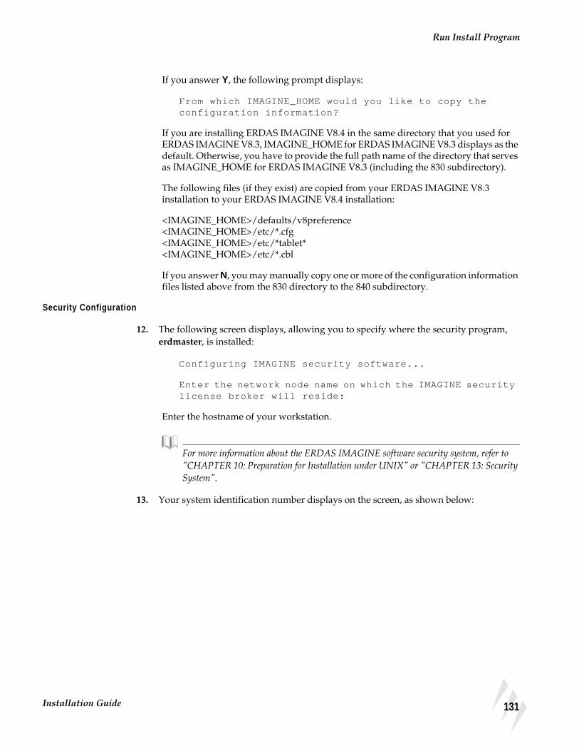
Run Install Program
If you answer Y, the following prompt displays:
From which IMAGINE_HOME would you like to copy theconfiguration information?
If you are installing ERDAS IMAGINE V8.4 in the same directory that you used forERDAS IMAGINE V8.3, IMAGINE_HOME for ERDAS IMAGINE V8.3 displays as thedefault. Otherwise, you have to provide the full path name of the directory that servesas IMAGINE_HOME for ERDAS IMAGINE V8.3 (including the 830 subdirectory).
The following files (if they exist) are copied from your ERDAS IMAGINE V8.3installation to your ERDAS IMAGINE V8.4 installation:
<IMAGINE_HOME>/defaults/v8preference<IMAGINE_HOME>/etc/*.cfg<IMAGINE_HOME>/etc/*tablet*<IMAGINE_HOME>/etc/*.cbl
If you answer N, you may manually copy one or more of the configuration informationfiles listed above from the 830 directory to the 840 subdirectory.
Security Configuration
12. The following screen displays, allowing you to specify where the security program,erdmaster, is installed:
Configuring IMAGINE security software...
Enter the network node name on which the IMAGINE securitylicense broker will reside:
Enter the hostname of your workstation.
For more information about the ERDAS IMAGINE software security system, refer to"CHAPTER 10: Preparation for Installation under UNIX" or "CHAPTER 13: SecuritySystem".
13. Your system identification number displays on the screen, as shown below:
131Installation Guide

Standard CD-ROM Installation
Your system ID number is
System identification number:080009f0468f
Please write this system identifier on your SecurityCodewords Request Form.
To obtain the necessary security codewords to secure thissystem, follow the instructions on your SecurityCodewords Request Form. This form is located in theImportant Information material.
Press RETURN to continue...
The system ID is a 12-digit hexadecimal number (i.e., a sequence of digits 0 through 9and characters “a” through “f”).
Write down your system ID number on the Security Codewords Request Form located inthe Important Information material.
ERDAS IMAGINE V8.3 users: If you have ERDAS IMAGINE V8.3 you need to receivenew codewords for ERDAS IMAGINE V8.4. The security broker for ERDAS IMAGINEV8.4 recognize the codewords used with ERDAS IMAGINE V8.3 and the new ERDASIMAGINE V8.4 codewords. If you are working with both versions of ERDAS IMAGINE,use the security broker from V8.4. During installation, enter your V8.4 codewords firstand then enter your V8.3 codewords.
Security Codewords
14. Send the Security Codewords Request Form to ERDAS Codeword Support via theERDAS web site (www.erdas.com), fax, e-mail, or mail to receive your securitycodewords. These codewords protect the software against unauthorized use bydetermining which modules you can use, the number of users, and the expiration datefor the modules.
NOTE: It may take ERDAS up to 8 business hours to process your security codewords.
15. After the security system is installed, the following screen displays, explaining how toenter the security codewords.
132 ERDAS IMAGINE

Run Install Program
The security codewords you received from ERDAS are placedinto the file
<IMAGINE_HOME>/etc/erdas_codewords
with the program <IMAGINE_HOME>/install/enter_codewd.
If you have obtained your system's security codewordsfrom ERDAS, you may run the codeword entry program nowby answering 'Y' at the next prompt.
If you have not yet obtained your codewords, answer 'N'at the next prompt and run<IMAGINE_HOME>/install/enter_codewd at a some latertime, but before running IMAGINE.
Do you wish to enter your codewords now? [Y]
Y = You have received the security codewords from ERDAS Codeword Support andyou are ready to enter them into the system. Proceed to step 16.
N = You have not received the security codewords from ERDAS Codeword Support,but you would like to continue with the customization of ERDAS IMAGINE. You mayenter the codewords at a later time. Go to step 17.
16. A screen displays, similar to the one below, asking you to enter the security codewordsthat you received from ERDAS. These codewords protect the software againstunauthorized use.
*** IMAGINE Security Codeword Entry/Edit Program ***
Enter new codeword and press RETURN(To exit, just press RETURN): V2HZBQ49HZHZ4NM27
The following message displays after the codewords have been entered:
Codeword entry program complete.
If you want to run ERDAS IMAGINE V8.3 along with ERDAS IMAGINE V8.4, youmust enter those codewords after you enter the V8.4 codewords. Please see "CHAPTER13: Security System" for step-by-step instructions on how to set up your system correctly.
NOTE: The following steps may be out of sequence in the installation process for your platform.
133Installation Guide

Standard CD-ROM Installation
Convert InternationalFonts
17. The following prompt enables you to convert the international fonts available inERDAS IMAGINE to a form suitable for the X Server.
This script will convert the .bdf fonts on<IMAGINE_HOME>/etc/fonts into a format suitable for theX Server on the <system architecture> architecture.
Do you wish to continue? [Y]
N = You are not using the international fonts (Hebrew, Greek, Russian, etc.) in ERDASIMAGINE, therefore you do not want to convert them.
Y = You do want to convert the fonts. The following prompt displays.
Compaq AlphaStationHP 9000Silicon Graphics
Please enter the directory containing the font building tools ‘bdftopcf’ and‘mkfontdir’: [/usr/bin/X11]
Press Return to accept the displayed default.
IBM RS/6000
NOTE: This platform requires the X11.fnt.util LPP from the AIX 4 CD-ROM. If this LPP isnot installed this step fails, but ERDAS IMAGINE still runs.
Please enter the directory containing the font building tools ‘bdftopcf’ and‘mkfontdir’: [/usr/lpp/X11/bin]
Press Return to accept the displayed default.
Sun SPARCstation
Sun Solaris 2.6 or 2.7
Please enter the directory containing the font building tools ‘bdftopcf’ and‘mkfontdir’: [<OPENWINHOME>/bin]
The default that displays are <OPENWINHOME>/bin, /usr/openwin/bin, or nodefault if <OPENWINHOME> is not defined and /usr/openwin/bin does not exist.
If there is a problem converting the fonts, an error message displays. You can convertthe fonts manually by running the <IMAGINE_HOME>/bin/setup_fonts script.
Automatic CD-ROMMounting
ERDAS IMAGINE software automatically mounts a CD-ROM if your system has thiscapability.
134 ERDAS IMAGINE

Run Install Program
See "CHAPTER 20: CD-ROM Device" for information on configuring your CD-ROMdevice so that it can be accessed by ERDAS IMAGINE software.
18. The following message displays as ERDAS IMAGINE verifies that your system canautomatically mount a CD-ROM:
Checking automatic CDROM mounting capability
Capability Exists
If ERDAS IMAGINE is able to automatically mount a CD-ROM on your system, thefollowing message displays:
Automatic CDROM mounting enabled on this system
Capability Does not Exist
If ERDAS IMAGINE is not able to automatically mount a CD-ROM on your system,the following message displays in addition to an error message:
IMAGINE may be unable to automatically mount CDROMs onthis system. Refer to the ‘ERDAS IMAGINE 8.4 Installingand Configuring’ manual for further information.
Press RETURN to continue...
135Installation Guide

Standard CD-ROM Installation
Setting Up Your System
19. The following message displays to inform you about setting up your system so that allusers can access ERDAS IMAGINE software:
136 ERDAS IMAGINE
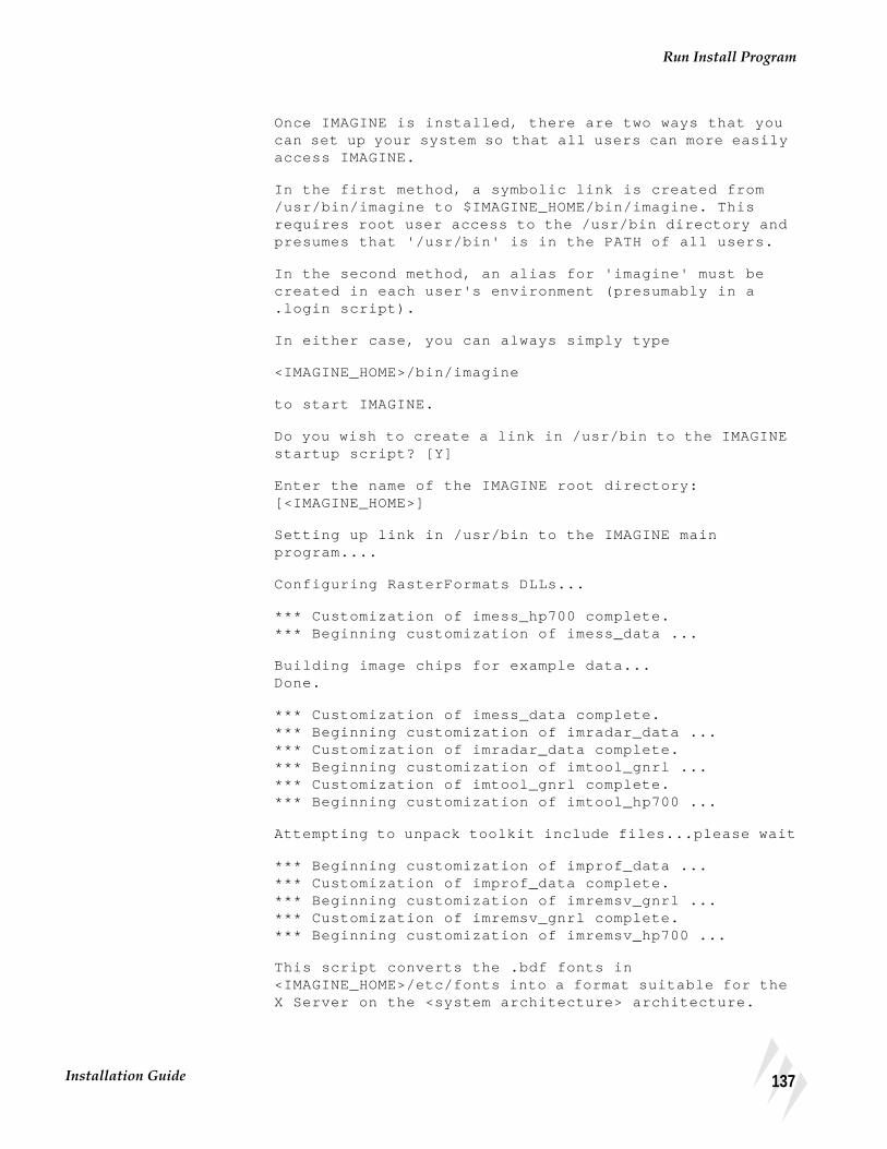
Run Install Program
Once IMAGINE is installed, there are two ways that youcan set up your system so that all users can more easilyaccess IMAGINE.
In the first method, a symbolic link is created from/usr/bin/imagine to $IMAGINE_HOME/bin/imagine. Thisrequires root user access to the /usr/bin directory andpresumes that '/usr/bin' is in the PATH of all users.
In the second method, an alias for 'imagine' must becreated in each user's environment (presumably in a.login script).
In either case, you can always simply type
<IMAGINE_HOME>/bin/imagine
to start IMAGINE.
Do you wish to create a link in /usr/bin to the IMAGINEstartup script? [Y]
Enter the name of the IMAGINE root directory:[<IMAGINE_HOME>]
Setting up link in /usr/bin to the IMAGINE mainprogram....
Configuring RasterFormats DLLs...
*** Customization of imess_hp700 complete.*** Beginning customization of imess_data ...
Building image chips for example data...Done.
*** Customization of imess_data complete.*** Beginning customization of imradar_data ...*** Customization of imradar_data complete.*** Beginning customization of imtool_gnrl ...*** Customization of imtool_gnrl complete.*** Beginning customization of imtool_hp700 ...
Attempting to unpack toolkit include files...please wait
*** Beginning customization of improf_data ...*** Customization of improf_data complete.*** Beginning customization of imremsv_gnrl ...*** Customization of imremsv_gnrl complete.*** Beginning customization of imremsv_hp700 ...
This script converts the .bdf fonts in<IMAGINE_HOME>/etc/fonts into a format suitable for theX Server on the <system architecture> architecture.
137Installation Guide

Standard CD-ROM Installation
20. The following message displays:
Do you wish to continue? [Y]
N = You are not using the international fonts (Hebrew, Greek, Russian, etc.) in ERDASIMAGINE, therefore you do not want to convert them. Installation will be complete. Y= You do want to convert the fonts. The following prompt displays:
Please enter the directory containing the font buildingtools 'bdftopcf' and 'mkfontdir': [/usr/bin/X11]Created /usr/imagine/840/etc/fonts/hp700
*** Customization of imremsv_hp700 complete.
--------------------Installation Report:--------------------IMAGINE Essentials was successfully installed.IMAGINE Vector was successfully installed.IMAGINE Advantage was successfully installed.IMAGINE Radar Interpreter was successfully installed.IMAGINE Toolkit Module was successfully installed.IMAGINE Professional was successfully installed.IMAGINE Remote Services was successfully installed.
Installation completed successfully
Running ERDASIMAGINE V8.3 and8.4
ERDAS IMAGINE V8.3 codewords cannot be used to secure ERDAS IMAGINE V8.4software. If you wish to run ERDAS IMAGINE V8.3 and ERDAS IMAGINE V8.4 atthe same time, there are two courses of action that may be followed:
• use different security broker nodes for ERDAS IMAGINE V8.3 and ERDASIMAGINE V8.4 software.
• enter your ERDAS IMAGINE V8.3 codewords while setting up ERDAS IMAGINEV8.4 security and make sure that the ERDAS IMAGINE V8.4 license broker getsstarted before running ERDAS IMAGINE V8.3 software. (Make sure that theERDAS IMAGINE V8.3 codewords are entered after the ERDAS IMAGINE V8.4codewords while setting up ERDAS IMAGINE V8.4 security.)
If you want to be able to continue running ERDAS IMAGINE V8.3 after you haveinstalled ERDAS IMAGINE V8.4, you need to perform the following steps.
NOTE: If your login shell is not C-shell, add the equivalent lines to your startup file.
138 ERDAS IMAGINE

Running ERDAS IMAGINE V8.3 and 8.4
1. Add two alias lines to the .cshrc file in your home directory on the system where youwant to continue to run ERDAS IMAGINE V8.3. Open the .cshrc file and enter thefollowing lines:
alias imagine83 ’<IMAGINE_HOME for v.8.3>/bin/imagine’
alias imagine84 ’<IMAGINE_HOME for v.8.4>/bin/imagine’
2. Save the .cshrc file, and log out (or source the new .cshrc file).
3. Use the appropriate alias to start up the version of ERDAS IMAGINE that you want touse.
NOTE: These steps need to be repeated for every user that is running both ERDAS IMAGINEV8.3 and 8.4.
139Installation Guide

Standard CD-ROM Installation
Starting ERDASIMAGINE
To start ERDAS IMAGINE, type one of the following in a command window:
• imagine
• imagine84 (if you have set up ERDAS IMAGINE V8.3 and V8.4, as described onpage 138).
NOTE: The software runs in the background, allowing you to run other applications from thatcommand window.
The ERDAS IMAGINE icon panel and a Viewer window opens.
If the installation was interrupted and/or some modules did not get properlycustomized, the following message appears when you start ERDAS IMAGINE:
WARNING: The customization for the following filesets has not yet been successfully completed. You may experience difficulties running IMAGINE. Please advise your IMAGINE system administrator of the problem.
imtkrun_hp700 imlzw_hp700
To correct the problem and customize the modules, run the following program foreach uncustomized module:
# <IMAGINE_HOME>/bin/customize <module name>
And substitute the name of a module (such as imtkrun_hp700 or imlzw_hp700 in theexample above) for <module name>.
Using IMAGINE On-Line Documentation
ERDAS IMAGINE On-Line Help manuals are accessed easily from the main icon panelby selecting Help | IMAGINE Online Documentation... . The Help menu is alsoavailable from the Session menu. When the On-Line Manuals title page is displayed,click on the Manuals button.
See the ERDAS IMAGINE Tour Guides manual for more information about the Helpsystem.
Adding AnotherSystem
If you would like to run ERDAS IMAGINE on more than one system, then you mustdo the following steps on every workstation where you run ERDAS IMAGINE. Yourlicense agreement from ERDAS states the number of systems on which you may runERDAS IMAGINE concurrently. If you are not sure about how many licenses you haveauthorized, please call ERDAS Codeword Support at 404/248-9000.
140 ERDAS IMAGINE

Adding Another System
<IMAGINE system> represents the workstation where you installed ERDASIMAGINE software and <Added system> represents the other workstation where youwant to run ERDAS IMAGINE software.
NOTE: For Silicon Graphics users, in order to add another system that uses the sameinstallation, you should have installed the Network File System (NFS) Subsystem when youinstalled IRIX.
1. Log in to the <IMAGINE system> as root.
2. Make an appropriate entry in the /etc/exports or /etc/dfs/dfstab file to make files inthe <IMAGINE_HOME> directory available to the <Added system> through thenetwork file system (NFS).
You may also use the following utilities to accomplish this:
• HP - sam
• IBM - smit
• SGI - System Manager
• Sun (Solaris only) - modify the /etc/dfs/dfstab file
3. Reboot the system.
4. Log in to the <Added system> as root.
5. # mkdir <IMAGINE_HOME>
This command creates the directory <IMAGINE_HOME> to serve as the NFS mountpoint.
6. # mount <IMAGINE system>:<IMAGINE_HOME> <IMAGINE_HOME>
This step mounts the <IMAGINE_HOME> directory from the<IMAGINE system> onto the <Added system>’s <IMAGINE_HOME> directory.
Compaq AlphaStation
Add the following line to the /etc/fstab file so that ERDAS IMAGINE is mountedevery time you boot the system:
<IMAGINE_HOME>@<IMAGINE system> <IMAGINE_HOME> nfs rw,bg,soft 0 0
HP 9000
Add the following line to the /etc/fstab file so that ERDAS IMAGINE is mountedevery time you boot the system:
<IMAGINE system>:<IMAGINE_HOME> <IMAGINE_HOME> nfs rw,soft,bg 0 0 16388
141Installation Guide

Standard CD-ROM Installation
IBM RS/6000
Execute the command below and follow the instructions. Specify both for the questionstating MOUNT now, add entry to /etc/filesystems or both? so that ERDASIMAGINE is mounted every time you boot the system.
# smit mknfsmnt
Silicon Graphics
Add the following line to the /etc/fstab file so that ERDAS IMAGINE is mountedevery time you boot the system:
<IMAGINE system>:<IMAGINE_HOME> <IMAGINE_HOME> nfs rw,soft,bg 0 0
Sun SPARCstation
Sun Solaris 2.6 or 2.7
Add the following line to the /etc/dfs/dfstab file so that ERDAS IMAGINE ismounted every time you boot the system:
<IMAGINE system> :<IMAGINE_HOME> - <IMAGINE_HOME> nfs rw yes -
7. Perform the following commands to run the setup_system script.
# cd <IMAGINE_HOME>/install
# ./setup_system
You must do this on every workstation where you want to run ERDAS IMAGINE.
Refer to the Configuring portion for this manual if you would like to access a printer,plotter, or digitizer from the added platform.
Adding MoreModules
If you would like to add another module after you have already installed ERDASIMAGINE software, you need to do one of the following:
• If you want to add a module that you selected in step 6. on page 127, but did notenter a security codeword for this module, then go to the “Module was Selected”section below.
• If you want to add a module that you did not select in step 6. on page 127, then goto the “Setting Up Your System” section below.
Module was Selected Run the ERDAS Security Codeword Entry/Edit Program (enter_codewd), and followthe instructions to enter the codeword for the new module.
# <IMAGINE_HOME>/install/enter_codewd
142 ERDAS IMAGINE
Error Messages
Replace <IMAGINE_HOME> with the location of the subdirectory where ERDASIMAGINE was installed, for example /usr/imagine/840.
The new module is now secured and ready for use. Module was Not Selected
To add a module that was not loaded when you previously installed the software youneed to do the following steps:
• Start at step 1. on page 122, and when you get to step 6., select only the module(s)you want to add.
• After you select the module(s), run the ERDAS Security Codeword Entry/EditProgram, enter_codewd, and follow the instructions to enter the codeword for thenew module.
# <IMAGINE_HOME>/install/enter_codewd
The new module is now secured and ready for use.
Error Messages Refer to the Error Messages section at the end of "CHAPTER 13: Security System" ifyou get any error messages during the installation process.
143Installation Guide

Standard CD-ROM Installation
144 ERDAS IMAGINE

CHAPTER 12Advanced CD-ROM Installation
Advanced vs.StandardInstallation
This section contains the steps for installing ERDAS IMAGINE software on a UNIXworkstation.
Advanced Installation
If you are installing the software on a workstation that is connected to a network witha remote CD-ROM, you must follow the instructions in this chapter. You must alsofollow these instructions if you are installing the security program, erdmaster, on adifferent workstation from where you are installing ERDAS IMAGINE software, or ifyou are not installing the software from the root account.
Standard Installation
If you are installing the software on a stand-alone system (one workstation), or on asystem on a network with a local CD-ROM drive, then you should follow theinstructions in"CHAPTER 11: Standard CD-ROM Installation". When you follow theStandard Installation instructions, you need to have access to the root account, andinstall the security program, erdmaster, on the same workstation where you areinstalling ERDAS IMAGINE software. If the configuration you want is other than this,or if you have a remote CD-ROM drive, then you need to follow the instructions in thischapter.
NOTE: The Standard Installation process is easier.
The proper user accounts must already be configured. You must have at least one useraccount that may access ERDAS software. See "CHAPTER 10: Preparation forInstallation under UNIX"for information on setting up user accounts.
Remote CD-ROMdrive
Installing ERDAS IMAGINEon this workstation
Installing erdmaster onthis workstation
145Installation Guide
Advanced CD-ROM Installation
Remote Services
ERDAS IMAGINE V8.4 includes a Remote Services module that enables you to installerdmaster, the security program, on a remote machine. This module also providesremote tape and print capabilities. For example, with this module installed, you canaccess a printer that is connected to another platform without having any othermodules loaded on that platform. The remote platform must be a platform supportedby ERDAS IMAGINE, and the device (tape drive or printer) that you are accessingmust also be supported by ERDAS IMAGINE on that platform. Steps for installing thismodule are in "CHAPTER 23: Remote Services".
System Architecture The phrase <system architecture> is used in examples throughout this manual. Thisphrase is replaced by the actual name of your system architecture in the installationprompts and diagnostic messages. This is a list of all of the system architectures thatare supported by ERDAS IMAGINE:
• decosf for Compaq AlphaStation workstations
• hp700 for HP 9000 workstations
• rs6000 for IBM RS/6000 workstations
• sgi for Silicon Graphics workstations
• sun4sol for Sun SPARCstations using Solaris 2.6 or 2.7
Log in to Root or Non-root Account
It is not necessary to log in to the root account to install ERDAS IMAGINE software.However, depending upon your system, there may be certain preinstallation setupsteps that require root user authority (e.g., mounting devices and file systems). Also, ifyou do not use the root account to install the software, you may not be able to create alink in the /usr/bin directory to the ERDAS IMAGINE startup script. (This step is notnecessary to run ERDAS IMAGINE, but it allows you to provide ERDAS IMAGINEusers with an easy way to access ERDAS IMAGINE without addressing each userindividually.) For these reasons, it may be more convenient to install ERDASIMAGINE software as the root user. Perform the step below if you would like to installERDAS IMAGINE from the root account. Otherwise, log in to a different account onthe system.
Throughout the rest of this chapter any reference to the <HOME> directory refers to thelogin directory of the account you are using to install ERDAS IMAGINE software. If youare using the root account, <HOME> refers to /, the root directory.
1. Log in to the root account.
login: root
On each UNIX system, there is an account called the root account. To install ERDASIMAGINE software from the root account, you must know the password (if any) to theroot account and gain access to the root account.
Also, a CD-ROM drive must be installed on the network, and the ERDAS IMAGINEinstallation CD must be inserted properly into the CD-ROM drive.
2. Check to see if erdmaster is running:
146 ERDAS IMAGINE

Access Install Program from a Local CD-ROM Drive
All Other Workstations ps -ef | grep erdmaster
3. If erdmaster is running, kill it:
kill -9 <pid>
Access InstallProgram from aLocal CD-ROM Drive
These commands are used when installing ERDAS IMAGINE on a local system with aCD-ROM drive connected.
Verify that the ERDAS IMAGINE CD/caddy has been properly inserted into the CD-ROM drive.
Some systems may have a CD daemon running to automatically mount a CD-ROMdrive when a CD is inserted. On Sun Solaris 2.6 or 2.7 the daemon is vold; on SiliconGraphics it is mediad. If your system is running a CD daemon, go to step 5. on page149.
4. If your system is not running a CD daemon, enter the following commands to be ableto run the installation programs from a CD-ROM drive. If the <mount point> directorydoes not exist, you must create it. Replace <device name> with the name of the CD-ROM device file for your system.
NOTE: You may need to be logged in as root to perform these steps.
Compaq AlphaStation
# mkdir <mount point>
# mount -r -t cdfs -o noversion,rrip <device name> <mountpoint>
# cd <mount point>
Example: # mkdir /cdrom# mount -r -t cdfs -o noversion,rrip /dev/rz4c/cdrom# cd /cdrom
HP 9000
HPUX 11.00
# mkdir <mount point>
# mount -r -F cdfs <device name> <mount point>
# cd <mount point>
Example: # mkdir /cdrom# mount -r -F cdfs /dev/dsk/c1t2d0 /cdrom# cd /cdrom
Follow the instructions under "Run Install Program" on page 153.
147Installation Guide

Advanced CD-ROM Installation
IBM RS/6000
# mkdir <mount point>
# mount -v cdrfs -p -r <device name> <mount point>
# cd <mount point>
Example: # mkdir /cdrom# mount -v cdrfs -p -r /dev/cd0 /cdrom# cd /cdrom
Go to step 1. on page 153 and follow the instructions under “Access Install Programfrom a Remote CD-ROM Drive”.
Silicon Graphics
NOTE: If the mediad daemon is running, the CD mounts automatically. Proceed to step 5.
# mkdir <mount point>
# mount -o setx -t iso9660 <device name> <mount point>
# cd <mount point>
Example: # mkdir /cdrom# mount -o setx -t iso9660 /dev/scsi/sc1d6l0 /cdrom# cd /cdrom
Go to step 1. on page 153 and follow the instructions under “Access Install Programfrom a Remote CD-ROM Drive”.
Sun SPARCstation
Sun Solaris 2.6 or 2.7
NOTE: If the vold daemon is running, the CD mounts automatically. Proceed to step 5.
# mkdir <mount point>
# mount -r -F hsfs <device name> <mount point>
# cd <mount point>
Example: # mkdir /cdrom# mount -r -F hsfs /dev/sr0 /cdrom# cd /cdrom
Follow the instructions under "Run Install Program" on page 153.
148 ERDAS IMAGINE

Access Install Program from a Remote CD-ROM Drive
5. If your system is running a CD daemon, enter the following command to changedirectory:
NOTE: The mount point may be different if your System Administrator has changed thedefault. Therefore, the path specified below may be different for your system.
Compaq AlphaStation
HP 9000
IBM RS/6000 Not applicable - go to step 1. on page 153 and follow the instructions under “AccessInstall Program from a Remote CD-ROM Drive”.
Silicon Graphics
# cd /CDROM
Follow the instructions under "Run Install Program" on page 153.
Sun SPARCstation
Sun Solaris 2.6 or 2.7
# cd /cdrom/imagine840_u
Follow the instructions under "Run Install Program" on page 153.
Access InstallProgram from aRemote CD-ROMDrive
These commands are used when installing ERDAS IMAGINE on a local system andthe CD-ROM drive is connected to a remote system on the network. You need to dosome steps on both systems. These instructions assume that the remote workstation isrunning the same operating system as the local workstation. If this is not the case, usethe appropriate commands for the system in use.
NOTE: These steps require the use of the network file system (NFS) on both systems (local andremote). You may need to be logged in as root to perform these steps.
Verify that the ERDAS IMAGINE CD or caddy has been properly inserted into the CD-ROM drive.
Some systems may have a CD daemon running to automatically mount a CD-ROMdrive when a CD is inserted. On Sun Solaris 2.6 or 2.7, the daemon is vold; on SiliconGraphics it is mediad. If your remote system is running a CD daemon, go to step 7.
6. If your remote system is not running a CD daemon, enter one of the commands, below,on the remote system to mount the CD-ROM. If the <mount point> directory does notalready exist, you must create it. Replace <device name> with the name of the CD-ROMdevice file for your system.
149Installation Guide

Advanced CD-ROM Installation
Compaq AlphaStation
# mkdir <mount point>
# mount -r -t cdfs -o noversion,rrip <device name> <mountpoint>
# cd <mount point>
Example: # mkdir /cdrom# mount -r -t cdfs -o noversion,rrip /dev/rz4c /cdrom# cd /cdrom
HP 9000
HPUX 11.00
# mkdir <mount point>
# mount -r -F cdfs <device name> <mount point>
# cd <mount point>
Example: # mkdir /cdrom# mount -r -F cdfs /dev/dsk/c1t2d0 /cdrom# cd /cdrom
IBM RS/6000
# mkdir <mount point>
# mount -v cdrfs -p -r <device name> <mount point>
# cd <mount point>
Example: # mkdir /cdrom# mount -v cdrfs -p -r /dev/cd0 /cdrom# cd /cdrom
Silicon Graphics
NOTE: If the mediad daemon is running, the CD mounts automatically. Proceed to step 7.
# mkdir <mount point>
# mount -o setx -t iso9660 <device name> <mount point>
# cd <mount point>
Example: # mkdir /cdrom# mount -o setx -t iso9660 /dev/scsi/sc1d6l0 /cdrom# cd /cdrom
150 ERDAS IMAGINE
Access Install Program from a Remote CD-ROM Drive
Sun SPARCstation
Sun Solaris 2.6 or 2.7
NOTE: If the vold daemon is running, the CD mounts automatically. Go to step 8.
# mkdir <mount point>
# mount -r -F hsfs <device name> <mount point>
# cd <mount point>
Example: # mkdir /cdrom# mount -r -F hsfs /dev/sr0 /cdrom# cd /cdrom
7. Verify that the export file on the remote machine contains an entry for the <mountpoint> with read-only permission, as in the examples below:
Sun Solaris 2.6 or 2.7 Only in export file /etc/dfs/dfstab
share -F nfs -o ro <mount point>
All other workstations in export file /etc/exports
<mount point> -ro
If the export file was not already on this system, then you need to reboot the system.
8. Use the following command on the remote system to export the /cdrom directory toyour network:
Compaq AlphaStation Not applicable - export is automatic. Proceed to step 9.
HP 9000
HPUX 11.00
# /usr/sbin/exportfs -a
IBM RS/6000
# /usr/etc/exportfs -a
Silicon Graphics
# /usr/etc/exportfs -a
Sun SPARCstation
Sun Solaris 2.6 or 2.7
# /usr/sbin/shareall
151Installation Guide
Advanced CD-ROM Installation
9. On the local system (the system where you are installing ERDAS IMAGINE) you needto create the <mount point> directory if it does not already exist.
# mkdir <mount point>
10. Use the following command on the local system to mount the CD-ROM from the remoteworkstation. Replace <remote mount point> with the name of the mount point createdon the remote machine in step 6. on page 149.
# mount <remote hostname>:<remote mount point> <mountpoint>
or if the remote machine was running a CD daemon,
Silicon Graphics withmediad
# mount <remote hostname>:/CDROM <mount point>
Sun SPARCstationSolaris 2.6 or 2.7 withvold # mount <remote hostname>:/cdrom/imagine840_u <mount
point>
11. Use the command below to change directory on the local system.
# cd <mount point>
Follow the instructions under "Run Install Program" on page 153.
152 ERDAS IMAGINE

Run Install Program
Run Install Program
1. Now that you have access to the installation programs from the CD, you are ready touse them to install the software. To install ERDAS IMAGINE software, enter thiscommand:
# ./install.cd advanced
2. As the installation program begins, a welcome screen is displayed:
Welcome to the IMAGINE installation script.
During the installation procedure, if you want to createa shell for your use, enter an exclamation point (!) inresponse to any prompt. On exit from the shell, the lastprompt displayed before the shell was created will be re-displayed for you to answer.
Also, if a prompt has a default response, this responsewill be displayed in brackets (e.g., [default value]).This default value can be selected simply by hittingRETURN.
Press RETURN to continue...
3. Does the CDROM drive reside on a remote node? [N] N
Please read the text on licensing. If you used NFS to mount the CD-ROM, then youneed to enter N. When a CD-ROM is NFS mounted, it becomes local.
4. Please enter the mount point for the CDROM: [/cdrom]: /cdrom
The mount point must be the directory that was created above. The default is /cdromfor all systems without a CD daemon running. The default is /cdrom/imagine840_u onSun Solaris 2.6 or 2.7 systems with the vold daemon running and /CDROM on SiliconGraphics systems with mediad running. Press Return to accept the default.
Select Y to continue to the next step or N to exit the Installation program.
Installation Directory
5. Please enter the installation directory name: [/usr/imagine] /usr/imagine
Enter the name of the directory where ERDAS IMAGINE software is installed, such as/usr/imagine. This directory is created if it does not already exist, then a subdirectoryis created within this directory with the ERDAS IMAGINE version number as its name(e.g., /usr/imagine/840). ERDAS IMAGINE is loaded into this subdirectory. Thisprevents you from overwriting a previous version of ERDAS IMAGINE (e.g., V8.3) onyour system.
153Installation Guide

Advanced CD-ROM Installation
While the directory is being created, the following message displays:
Created <install directory>/840
NOTE: Throughout the rest of this manual, <IMAGINE_HOME> refers to the location of thesubdirectory that was created (e.g., /usr/imagine/840). This is where ERDAS IMAGINEsoftware resides.
Selecting Modules Follow the instructions below to select the modules to install.
6. A screen displays similar to the one below, listing the modules that you may install.
If any modules have already been installed in the specified installation directory, an Xappears before the name of the module. An A indicates that the module is available forinstallation, and an I indicates that the module is not available on the media, but hasalready been installed in the specified directory.
Please wait...searching for installable modules in
directory /cdrom
Table 12-1 Installable Modules
data-
decosf-
gnrl-
hp700-
rs6000-
sgi-
sun4sol-
A A A A A A A 1. IMAGINE Essentials
A A A A A A 2. IMAGINE Vector
A A A A A A A 3. IMAGINE Advantage
A A A A A A A 4. IMAGINE Radar Interpreter
A A A A A A A 5. IMAGINE Professional
A A A A A A A 6. IMAGINE VirtualGIS
A A A A A 7. IMAGINE LZW
A A A A A A A 8. IMAGINE StereoSAR DEM
A A A A A A A 9. IMAGINE IFSAR DEM
A A A A A A A 10. IMAGINE OrthoRadar
A A A A A A 11. IMAGINE Remote Services
12. IMAGINE Install ALL Modules
13. ABORT INSTALLATION
154 ERDAS IMAGINE

Run Install Program
The above modules may be installed. An X in the key at the left indicates that theparticular fileset of the given module has already been installed in the selectedinstallation directory and that same fileset is also available on the installation medium.An A in the key indicates that the fileset is available on the installation medium, buthas not yet been installed.Finally, an I in the key indicates that the fileset is notavailable on the current installation medium, but has been installed in the installationdirectory (/usr/imagine).
Select the module(s) you wish to install by specifying the product's number separatedby spaces (e.g., 1 3 4): [2 5]
NOTE: You should select only the modules for which you have a license. The security programprevents you from running unlicensed modules. Installing unlicensed modules needlesslyconsumes disk space.
NOTE: Selecting the IMAGINE Install ALL Modules does not install the IMAGINERemote Services module. If you wish to install it in addition to all of the others, you mustspecify both the IMAGINE Install ALL Modules product number and the IMAGINERemote Services product number.
Essentials Module
The IMAGINE Essentials module is required to run any ERDAS IMAGINE module.
Advantage Module
When you load the IMAGINE Advantage module, the IMAGINE Essentials module isalso automatically loaded. Both of these filesets are required to run the IMAGINEAdvantage module.
Professional Module
When you load the IMAGINE Professional module, the IMAGINE Essentials,IMAGINE Advantage, and IMAGINE Radar modules are also automatically loaded.All of these filesets are required for, or included in, the IMAGINE Professional module.
7. After you select the modules to load, a screen similar to the one below displays:
155Installation Guide

Advanced CD-ROM Installation
The following modules were selected...
IMAGINE EssentialsIMAGINE VectorIMAGINE AdvantageIMAGINE Radar InterpreterIMAGINE ProfessionalIMAGINE Remote Services
*** Be aware that you will only be able to use those ****** modules for which you have obtained security ****** codewords. Installing unsecured modules will only ****** consume disk space unnecessarily ***
Are these the modules you want to install [Y]
Y = These are the modules to be installed. Go to step 8.
N = These are not the modules to be installed. Repeat step 6.
8. A message similar to the following explains the different types of filesets and allowsyou to select those you wish to install. The default selection list shows the currentsystem architecture. You may also select other system architectures that are displayedin the module selection screen (step 6.).
Each module is packaged into separately installablefilesets. The 'gnrl' fileset for each module containsarchitecture independent files for that module. Thisfileset should be installed if this is the first time themodule is being installed. The 'data' fileset containssample data for the module and is not required. The othervalid fileset types contain architecture specific filesfor one of the supported IMAGINE architectures. Youshould choose the type(s) appropriate for theworkstation(s) on which you will be running IMAGINE.
Which fileset types do you wish to install? [gnrl sun4data]
If you are installing ERDAS IMAGINE for the first time, then you should install thegnrl fileset, the data fileset, and the architecture specific fileset (e.g., sun4).
If you are using the Remote Services module, you must enter both fileset types at thisprompt separated by a space.
156 ERDAS IMAGINE

Run Install Program
Disk Space
9. The following message informs you of the amount of disk space that is consumed:
Installing the current module/fileset selection willconsume an additional <XXX> kilobytes of disk space.
Do you wish to proceed with the current module/filesetselection? [Y]:
Y = The installation process proceeds.
N = Do not proceed with this module/fileset selection. Return to step 6.
If there is not enough disk space to load the modules you selected, then the followingmessage displays:
This may exceed the free disk space available in thefilesystem in which the installation directoryresides!!!
You need to free up more disk space before continuing the installation process.
10. After several seconds, messages similar to the ones below display while the modulesare unloading from the CD. The modules are unloaded in a compressed format andthen be decompressed. You cannot use any of the modules until you complete theinstallation and security system process.
Uncompressing/de-archiving imess_gnrl...Uncompressing/de-archiving imess_hp700...Uncompressing/de-archiving imess_data...Uncompressing/de-archiving imvect_gnrl...Uncompressing/de-archiving imvect_hp700...Uncompressing/de-archiving imadvan_gnrl...Uncompressing/de-archiving imadvan_hp700...Uncompressing/de-archiving imradar_gnrl...Uncompressing/de-archiving imradar_hp700...Uncompressing/de-archiving imradar_data...Uncompressing/de-archiving imtool_gnrl...Uncompressing/de-archiving imtool_hp700...Uncompressing/de-archiving improf_gnrl...Uncompressing/de-archiving improf_hp700...Uncompressing/de-archiving improf_data...Uncompressing/de-archiving imremsv_gnrl...Uncompressing/de-archiving imremsv_hp700...
NOTE: The actual messages displayed depends upon the modules installed.
This step may take up to one hour if you are installing all modules.
157Installation Guide

Advanced CD-ROM Installation
11. The following prompt enables you to copy global configuration information fromanother installed version of ERDAS IMAGINE (e.g., ERDAS IMAGINE V8.3).
Would you like to copy initial configuration informationfrom another installed version of IMAGINE? [Y]
If you answer Y, the following prompt displays:
From which IMAGINE_HOME would you like to copy theconfiguration information?
If you are installing ERDAS IMAGINE V8.4 in the same directory that you used forERDAS IMAGINE V8.3, IMAGINE_HOME for ERDAS IMAGINE V8.3 displays as thedefault. Otherwise, you have to provide the full path name of the directory that servesas IMAGINE_HOME for ERDAS IMAGINE V8.3 (including the 830 subdirectory).
The following files (if they exist) are copied from your ERDAS IMAGINE V8.3installation to your ERDAS IMAGINE V8.4 installation:
<IMAGINE_HOME>/defaults/v8preference<IMAGINE_HOME>/etc/*.cfg<IMAGINE_HOME>/etc/*tablet*<IMAGINE_HOME>/etc/*.cbl
If you answer N to the prompt that asks if you want to copy configuration information,you can perform these steps manually.
Security Configuration
License Broker System
The license broker system is the workstation where you install the ERDAS securityprogram, erdmaster, and the security codewords.
For more information about the IMAGINE software security system, refer to "CHAPTER10: Preparation for Installation under UNIX"or "CHAPTER 13: Security System".
12. The following screen displays, allowing you to specify where the security program,erdmaster, is installed:
Configuring IMAGINE security. Enter the network node nameon which the IMAGINE security license broker will reside:
Enter the full hostname of the workstation where you want to install the securityprogram, erdmaster. This workstation becomes the license broker and the securityprogram resides here.
The installation/security process is easier if you install the security program onto the sameworkstation where you are installing the software.
158 ERDAS IMAGINE

Run Install Program
• If you would like to install the security program, erdmaster, on the sameworkstation where you are installing ERDAS IMAGINE software, then go to step13.
• If you would like to install the security program, erdmaster, on a differentworkstation from where you are installing ERDAS IMAGINE software, then youmust follow the steps in the next section. You must also follow these steps if youare using the Remote Services module.
Installing Security Program on a Different Workstation
If you are installing the security program, erdmaster, on a different workstation fromwhere you are installing ERDAS IMAGINE V8.4 software and ERDAS IMAGINE V8.4software is not accessible through <IMAGINE_HOME> on the license brokerworkstation, then the following message displays:
Directory <IMAGINE_HOME> not accessible on host <LicenseBroker>
If this message does not display, go to step 13.
You must do the following steps to install the security program onto the license brokerworkstation. You cannot run the software until you execute the install_broker shell scripton the license broker workstation.
You may perform the following steps after you complete the installation process.
<IMAGINE system> represents the workstation where you installed ERDASIMAGINE software and <License Broker> represents the system where you want toinstall the security program, erdmaster.
• Log in to the <IMAGINE system> as root.
• Make an appropriate entry in the /etc/exports file to make files in the<IMAGINE_HOME> directory available to the <License Broker> through thenetwork file system (NFS).
• Reboot the system.
• Log in to the <License Broker> as root.
• # mkdir <IMAGINE_HOME>
This command creates the directory <IMAGINE_HOME> to serve as the NFS mountpoint.
• # mount <IMAGINE system>:<IMAGINE_HOME> <IMAGINE_HOME>
This step mounts the <IMAGINE_HOME> directory from the <IMAGINE system>onto the <License Broker>’s <IMAGINE_HOME> directory.
159Installation Guide

Advanced CD-ROM Installation
Compaq AlphaStation
Add the following line to the /etc/fstab file so that ERDAS IMAGINE is mountedevery time you boot the system:
<IMAGINE_HOME>@<IMAGINE system> <IMAGINE_HOME> nfs rw,bg,soft 0 0
HP 9000
This step mounts the <IMAGINE_HOME> directory from the <IMAGINEsystem> onto the <License Broker>’s <IMAGINE_HOME> directory.
Add the following line to the /etc/fstab file so that ERDAS IMAGINE is mountedevery time you boot the system:
<IMAGINE system>:<IMAGINE_HOME> <IMAGINE_HOME> nfs rw,soft,bg 0 0 16388
IBM RS/6000
Execute the command below and follow the instructions. Specify both for the questionstating MOUNT now, add entry to /etc/filesystems or both? so that ERDASIMAGINE is mounted every time you boot the system.
# smit mknfsmnt
Silicon Graphics
On a Silicon Graphics workstation, you need to add the following line to the /etc/fstabfile so that ERDAS IMAGINE is mounted every time you boot the system:
<IMAGINE system>:<IMAGINE_HOME> <IMAGINE_HOME> rw 0 0
Sun SPARCstation
Sun Solaris 2.6 or 2.7
Add the following line to the /etc/dfs/dfstab file so that ERDAS IMAGINE ismounted every time you boot the system:
<IMAGINE system> :<IMAGINE_HOME> - <IMAGINE_HOME> nfs rw yes -
All UNIX Workstations
Perform the following steps on either the <IMAGINE system> or the <License Broker>workstation:
# cd <IMAGINE_HOME>/install# ./install_broker
You should be logged in as the same user whom you logged in as to perform theinstallation.
160 ERDAS IMAGINE

Run Install Program
License Broker Workstation
When running ERDAS IMAGINE on the license broker, the erdmaster program isstarted automatically if it is not already running.
When running ERDAS IMAGINE on a workstation other than the license broker, theerdmaster program is automatically started through the rsh command if it is notalready running.
To ensure that erdmaster is always running, place the following line in the appropriatesystem startup file of the license broker workstation.
NOTE: This requires root privilege.
<IMAGINE_HOME>/install/erdmaster -l /tmp/erdmaster.log
When using the method above, be sure to insert the erdmaster command line at a pointin the system startup file following any command that clears the /tmp directory.
If you do not have root privilege, you can set up the license broker machine to allowthe erdmaster program to be started automatically by ERDAS IMAGINE through thersh command. Give the following commands from the <IMAGINE system> on whichyou wish to run ERDAS IMAGINE:
# rlogin <License Broker>...# echo <IMAGINE system> >> $HOME/.rhosts# chmod 600 $HOME/.rhosts# exit
This creates the .rhosts file in your home directory on the <License Broker> machineand properly set permissions for the .rhosts file. Once erdmaster is running, otherusers may start ERDAS IMAGINE.
Proceed to step 13.
System ID Number
13. Your system identification number displays on the screen, as shown below:
161Installation Guide

Advanced CD-ROM Installation
Security license broker node installed locally.
Your system ID number is
System identification number:fe45f39a1efe
Please write this system identifier on your SecurityCodewords Request Form.
To obtain the necessary security codewords to secure thissystem, follow the instructions on your SecurityCodewords Request Form. This form is located in theImportant Information material.
Press RETURN to continue...
The system ID is a 12-digit hexadecimal number (i.e., a sequence of digits 0 through 9and characters a through f).
The security broker for ERDAS IMAGINE V8.4 recognizes the codewords used withERDAS IMAGINE V8.3 and the new ERDAS IMAGINE V8.4 codewords. If you areworking with both versions of ERDAS IMAGINE, use the security broker from V8.4.During installation, enter your V8.4 codewords first and then enter your V8.3 codewords.
Write down your system ID number on the Security Codewords Request Form located inthe Important Information material or on the ERDAS web site (www.erdas.com).
Security Codewords
14. Send the Security Codewords Request Form to ERDAS Codeword Support via theERDAS web site (www.erdas.com), fax, e-mail, or mail to receive your securitycodewords. These codewords protect the software against unauthorized use bydetermining which modules you can use, the number of users, and the expiration datefor the modules.
NOTE: It may take ERDAS up to 8 business hours to process your security codewords.
15. After the security system is installed, the following screen displays, explaining how toenter the security codewords:
162 ERDAS IMAGINE

Run Install Program
The security codewords you received from ERDAS are placedinto the file
<IMAGINE_HOME>/etc/erdas_codewords
with the program <IMAGINE_HOME>/install/enter_codewd.
If you have obtained your system's security codewordsfrom ERDAS, you may run the codeword entry program nowby answering 'Y' at the next prompt.
If you have not yet obtained your codewords, answer 'N'at the next prompt and run<IMAGINE_HOME>/install/enter_codewd at a some latertime, but before running IMAGINE.
Do you wish to enter your codewords now? [Y]
Y = You have received the security codewords from ERDAS Codeword Support andyou are ready to enter them into the system. Proceed to step 16.
N = You have not received the security codewords from ERDAS Codeword Support,but you would like to continue with the customization of IMAGINE. You may enterthe codewords at a later time. Proceed to step 17.
16. A screen displays, similar to the one below, asking you to enter the security codewordsthat you received from ERDAS. These codewords protect the software againstunauthorized use.
*** IMAGINE Security Codeword Entry/Edit Program ***
Enter new codeword and press RETURN(To exit, just press RETURN): V2HZBQ49HZHZ4NM27
The following message displays after the codewords have been entered:
Codeword entry program complete.
If you want to run ERDAS IMAGINE V8.3 along with ERDAS IMAGINE V8.4, youmust enter those codewords after you enter the V8.4 codewords. Please see "CHAPTER13: Security System"for step-by-step instructions on how to set up your system correctly.
NOTE: The following steps may be out of sequence in the installation process for your platform.
163Installation Guide

Advanced CD-ROM Installation
Convert InternationalFonts
17. The following prompt enables you to convert the international fonts available inERDAS IMAGINE to a form suitable for the X Server.
This script will convert the .bdf fonts on<IMAGINE_HOME>/etc/fonts into a format suitable for theX Server on the <system architecture> architecture.
Do you wish to continue? [Y]
Y = You do want to convert the fonts. The following prompt displays.
N = You are not using the international fonts (Hebrew, Greek, Russian, etc.) in ERDASIMAGINE, therefore you do not want to convert them.
Compaq AlphaStationHP 9000Silicon Graphics
Please enter the directory containing the font buildingtools ‘bdftopcf’ and ‘mkfontdir’: [/usr/bin/X11]
Press Return to accept the displayed default.
IBM RS/6000
NOTE: This platform requires the X11.fnt.util LPP from the AIX 4 CD-ROM.
Please enter the directory containing the font buildingtools ‘bdftopcf’ and ‘mkfontdir’: [/usr/lpp/X11/bin]
Press Return to accept the displayed default.
Sun SPARCstation
Sun Solaris 2.6 or 2.7
Please enter the directory containing the font buildingtools ‘bdftopcf’ and ‘mkfontdir’: [<OPENWINHOME>/bin]
The default that displays is <OPENWINHOME>/bin, /usr/openwin/bin, or nodefault if <OPENWINHOME> is not defined and /usr/openwin/bin does not exist.
If there is a problem converting the fonts, an error message displays. You can convertthe fonts manually by running the <IMAGINE_HOME>/bin/setup_fonts script.
Automatic CD-ROMMounting
ERDAS IMAGINE software automatically mounts a CD-ROM if your system has thiscapability.
164 ERDAS IMAGINE

Run Install Program
18. The following message displays as ERDAS IMAGINE verifies that your system canautomatically mount a CD-ROM:
Checking automatic CDROM mounting capability
Capability Exists
If ERDAS IMAGINE is able to automatically mount a CD-ROM on your system, thefollowing message displays:
Automatic CDROM mounting enabled on this system
See "CHAPTER 20: CD-ROM Device"for information on configuring your CD-ROMdevice so that it can be accessed by ERDAS IMAGINE software.
Capability Does not Exist
If ERDAS IMAGINE is not able to automatically mount a CD-ROM on your system,the following message displays in addition to an error message:
IMAGINE may be unable to automatically mount CDROMs onthis system. Refer to the ‘Configuring Peripherals’manual for further information.
Press RETURN to continue...
See "CHAPTER 20: CD-ROM Device"for more information on the error messages andmounting your CD-ROM.
165Installation Guide

Advanced CD-ROM Installation
Setting Up Your System The system setup message that displays depends on whether you are installing ERDASIMAGINE as root or not.
• If you are installing as root, go to step 19.
• If you are not installing as root, go to step 20.
Installing as Root
19. If you are installing ERDAS IMAGINE as root, the following message displays toinform you about setting up your system so that all users can access ERDAS IMAGINEsoftware:
Once IMAGINE is installed, there are two ways that youcan set up your system so that all users can more easilyaccess IMAGINE.
In the first method, a symbolic link is created from/usr/bin/imagine to $IMAGINE_HOME/bin/imagine. Thisrequires root user access to the /usr/bin directory andpresumes that '/usr/bin' is in the PATH of all users.
In the second method, an alias for 'imagine' must becreated in each user's environment (presumably in a.login script).
In either case, you can always simply type
<IMAGINE_HOME>/bin/imagine
to start IMAGINE.
Do you wish to create a link in /usr/bin to the IMAGINEstartup script? [Y]
Enter the name of the IMAGINE root directory:[<IMAGINE_HOME>]
Setting up link in /usr/bin to the IMAGINE mainprogram....
--------------------Installation Report:--------------------IMAGINE Essentials was successfully installed.IMAGINE Vector was successfully installed.IMAGINE Advantage was successfully installed.IMAGINE Radar Interpreter was successfully installed.IMAGINE Professional was successfully installed.IMAGINE Remote Services was successfully installed.
Installation completed successfully
166 ERDAS IMAGINE

Run Install Program
Not Installing as Root
20. If you are not installing ERDAS IMAGINE as root, the following message displays toinform you about setting up your system so that all users can access ERDAS IMAGINEsoftware:
Once IMAGINE is installed, there are two ways that youcan set up your system so that all users can more easilyaccess IMAGINE.
In the first method, a symbolic link is created from/usr/bin/imagine to $IMAGINE_HOME/bin/imagine. Thisrequires root user access to the /usr/bin directory andpresumes that '/usr/bin' is in the PATH of all users.
In the second method, an alias for 'imagine' must becreated in each user's environment (presumably in a.login script).
In either case, you can always simply type
<IMAGINE_HOME>/bin/imagine
to start IMAGINE.
Since you cannot currently modify the /usr/bin directory,you will not be able to create the /usr/bin/imagine link.You can either login as root at some later time andexecute the <IMAGINE_HOME>/bin/setup_system script or,for C-shell users, you can add the following line to the.login script for every user that wishes to accessIMAGINE:
alias imagine ’<IMAGINE_HOME>/bin/imagine \!*’
Press RETURN to continue...
--------------------Installation Report:--------------------IMAGINE Essentials was successfully installed.IMAGINE Vector was successfully installed.IMAGINE Advantage was successfully installed.IMAGINE Radar Interpreter was successfully installed.IMAGINE Professional was successfully installed.IMAGINE Remote Services was successfully installed.
Installation completed successfully
167Installation Guide

Advanced CD-ROM Installation
Running ERDASIMAGINE V8.3 and8.4
ERDAS IMAGINE V8.3 codewords cannot be used to secure IMAGINE V8.4 software.If you wish to run ERDAS IMAGINE V8.3 and 8.4 at the same time, there are twocourses of action that may be followed:
• use different security broker nodes for ERDAS IMAGINE V8.3 and ERDASIMAGINE V8.4 software
• enter your ERDAS IMAGINE V8.3 codewords while setting up ERDAS IMAGINEV8.4 security and make sure that the ERDAS IMAGINE V8.4 license broker getsstarted before running ERDAS IMAGINE V8.3 software. (Make sure that theERDAS IMAGINE V8.3 codewords are entered after the ERDAS IMAGINE V8.4codewords while setting up ERDAS IMAGINE V8.4 security.)
If you want to be able to continue running ERDAS IMAGINE V8.3 after you haveinstalled ERDAS IMAGINE V8.4, you need to perform the following steps.
NOTE: If your login shell is not C-shell, add the equivalent lines to your startup file.
1. Add two alias lines to the .cshrc file in your home directory on the system where youwant to continue to run ERDAS IMAGINE V8.3. Use a text edit window to open the.cshrc file and enter the following lines:
alias imagine83 ’<IMAGINE_HOME for v.8.3>/bin/imagine’
alias imagine84 ’<IMAGINE_HOME for v.8.4>/bin/imagine’
2. Save the .cshrc file, and log out (or source the new .cshrc file).
3. Use the appropriate alias to start up the version of ERDAS IMAGINE that you want touse.
NOTE: These steps need to be repeated for every user running both ERDAS IMAGINE V8.3and 8.4.
Starting ERDASIMAGINE
To start ERDAS IMAGINE, type one of the following in a command window:
• imagine
• imagine84 (if you have set up ERDAS IMAGINE V8.3 and 8.4, as described onpage 168).
NOTE: The software allows you to run other applications from that command window.
The ERDAS IMAGINE icon panel and a Viewer window opens.
168 ERDAS IMAGINE
Adding Another System
If the installation was interrupted and/or some modules did not get properlycustomized, you see the following when you start ERDAS IMAGINE:
WARNING: The customization for the following filesets has not yet been successfully completed. You may experience difficulties running IMAGINE. Please advise your IMAGINE system administrator of the problem.
imtkrun_hp700 imlzw_hp700
To correct the problem and customize the modules run the following program for eachuncustomized module:
# <IMAGINE_HOME>/bin/customize <module name>
And substitute the name of a module (such as imtkrun_hp700 or imlzw_hp700 in theexample above) for <module name>.
Using IMAGINE On-Line Documentation
ERDAS IMAGINE On-Line Help manuals are accessed easily from the main icon panelby selecting Help | IMAGINE Online Documentation . The Help menu is also availablefrom the Session menu. When the On-Line Manuals title page is displayed, click onthe Manuals button.
See the ERDAS IMAGINE Tour Guides manual or select Help from the IMAGINE iconpanel for more information about the Help system.
Adding AnotherSystem
If you would like to run ERDAS IMAGINE on more than one system, then you mustdo the following steps on every workstation where you run ERDAS IMAGINE. Yourlicense agreement from ERDAS states the number of systems on which you may runERDAS IMAGINE concurrently. If you are not sure about how many licenses you haveauthorized, please call ERDAS Codeword Support at 404-248-9000.
<IMAGINE system> represents the workstation where you installed ERDASIMAGINE software and <Added system> represents the other workstation where youwant to run ERDAS IMAGINE software.
NOTE: For Silicon Graphics users, in order to add another system that uses the sameinstallation, you should have installed the Network File System (NFS) Subsystem when youinstalled IRIX.
1. Log in to the <IMAGINE system> as root.
2. Make an appropriate entry in the /etc/exports file to make files in the<IMAGINE_HOME> directory available to the <Added system> through the networkfile system (NFS).
You may also use the following utilities to accomplish this:
169Installation Guide

Advanced CD-ROM Installation
• HP - sam
• IBM - smit
• SGI - System Manager
• Sun Solaris - modify the /etc/dfs/dfstab file
3. Reboot the system.
4. Log in to the <Added system> as root.
5. # mkdir <IMAGINE_HOME>
This command creates the directory <IMAGINE_HOME> to serve as the NFS mountpoint.
6. # mount <IMAGINE system>:<IMAGINE_HOME> <IMAGINE_HOME>
This step mounts the <IMAGINE_HOME> directory from the <IMAGINE system>onto the <Added system>’s <IMAGINE_HOME> directory.
Compaq AlphaStation
Add the following line to the /etc/fstab file so that ERDAS IMAGINE is mountedevery time you boot the system:
<IMAGINE_HOME>@<IMAGINE system> <IMAGINE_HOME> nfs rw,bg,soft 0 0
HP 9000
Add the following line to the /etc/fstab file so that ERDAS IMAGINE is mountedevery time you boot the system:
<IMAGINE system>:<IMAGINE_HOME> <IMAGINE_HOME> nfs rw,soft,bg 0 0 16388
IBM RS/6000
Execute the command below and follow the instructions. Specify both for the questionstating MOUNT now, add entry to /etc/filesystems or both? so that ERDASIMAGINE is mounted every time you boot the system.
# smit mknfsmnt
Silicon Graphics
On a Silicon Graphics workstation, you need to add the following line to the /etc/fstabfile so that ERDAS IMAGINE is mounted every time you boot the system:
<IMAGINE system>:<IMAGINE_HOME> <IMAGINE_HOME> nfs rw,soft,bg 0 0
170 ERDAS IMAGINE

Adding More Modules
Sun SPARCstation
Sun Solaris 2.6 or 2.7
Add the following line to the /etc/dfs/dfstab file so that ERDAS IMAGINE ismounted every time you boot the system:
<IMAGINE system>:<IMAGINE_HOME> - <IMAGINE_HOME> nfs rw yes -
7. Perform the following commands to run the setup_system script.
# cd <IMAGINE_HOME>/install# ./setup_system
You must do this on every workstation where you want to run ERDAS IMAGINE.
Refer to the Configuring section of this manual if you would like to access a printer,plotter, or digitizer from the added platform.
Adding MoreModules
If you would like to add another module after you have already installed ERDASIMAGINE software, you need to do one of the following:
• If you want to add a module that you selected in step 6., but did not enter a securitycodeword for this module, then go to the Module was Selected section below.
• If you want to add a module that you did not select in step 6., then go to theModule was Not Selected section below.
Module was Selected Run the ERDAS Security Codeword Entry/Edit Program (enter_codewd) on theworkstation where erdmaster, the security program resides. Follow the instructions toenter the codeword for the new module.
# <IMAGINE_HOME>/install/enter_codewd
The new module is now secured and ready for use.
Module was Not Selected In order to add a module that was not loaded when you previously installed thesoftware you need to do the following steps:
• Start at step 1. and when you get to step 6., select only the module(s) you want toadd.
• After you select the module, run enter_codewd, the ERDAS IMAGINE SecurityCodeword Entry/Edit Program on the workstation where erdmaster, the securityprogram, resides. Follow the instructions to enter the codeword for the newmodule(s).
# <IMAGINE_HOME>/install/enter_codewd
The new modules are now secured and ready for use.
171Installation Guide

Advanced CD-ROM Installation
Error Messages Refer to the Error Messages section at the end of "CHAPTER 13: Security System"if youget any error messages during the installation process.
172 ERDAS IMAGINE
CHAPTER 13Security System
This chapter is intended for system administrators who want to know more about theERDAS security system. It is not required that you read this for successful softwareinstallation.
Introduction The ERDAS security system is a client/server based system that uses a single licenseserver, erdmaster, to authorize requests for module usage by application clients on anetwork.
Definitions
The license broker is the host that is designated to run the ERDAS license server,erdmaster.
A license broker is identified through its system id. This is a platform dependentidentifier string obtained from the host that is unique among all hosts.
A module is a named, licensable product from ERDAS or other third party developer.Every module has a unique module ID.
Each module is secured through a security codeword. The security codeword is anencrypted form of the information pertinent to module licensing such as the moduleID, the system ID, the user count, the expiration date, or maximum version number.
Files and Environment Variables
• IMAGINE_HOME - Once the ERDAS IMAGINE environment is entered, theenvironment variable IMAGINE_HOME contains the full path of the top leveldirectory for this version of ERDAS IMAGINE.
• <IMAGINE_HOME>/etc/erdas_codewords This file contains the securitycodewords used by erdmaster to know which modules a client is authorized touse.
• <IMAGINE_HOME>/etc/secure.master This file contains the name of thelicense broker that should be contacted by a client to request module usageauthorization.
• ERDAS_ETC_PATH This environment variable controls what path is searchedby ERDAS IMAGINE to find the secure.master file. The default path set by thestart-up script of ERDAS IMAGINE is “.:<IMAGINE_HOME>/etc.”
• <IMAGINE_HOME>/install/*modules.lst These files are used to matchmodule names to module IDs and module descriptions. Both the license brokerand the application programs are generally only aware of module IDs. These filesare used to provide more informative messages at both the client and server end.
173Installation Guide

Security System
Services
• erdas-security81 The default port number on which the license broker listens forconnections is 5530. If there is a service entry (in /etc/services or an NIS servicesmap, whichever is being used) for erdas-security81, the license broker listens forconnections on the port associated with the service entry. Likewise, the clientcontacts the server on this same port. This service entry is not required.
Using erdmaster Use this syntax to run erdmaster:
<IMAGINE_HOME>/install/erdmaster [-l <log file>][-p <path>] [-a]
-l <log file> Specify a file to which messages are to be logged. The default is stderr .
-p <path>Override default path from which to read *modules.lst anderdas_codewords. By default, erdmaster looks for *modules.lst files in$IMAGINE_HOME/install. It looks for the erdas_codewords file in$IMAGINE_HOME/etc. By specifying an alternate path, you can tell erdmaster tolook for both files in <path>.
-aAUDIT mode execution. Generate messages when authorizationgranted/denied/returned.
When erdmaster is started automatically from ERDAS IMAGINE, $IMAGINE_HOME(the environment variable) is set to <IMAGINE_HOME> (where ERDAS IMAGINEactually is installed) and the flag '-l /tmp/erdmaster.log' flag is used. This isaccomplished by using the <IMAGINE_HOME>/bin/broker_start script. You caninvoke the broker_start script through a full path from a system start-up file if youwish to start erdmaster when the system reboots. This may be necessary, for instance,if you wish to put the license server on a machine that ERDAS IMAGINE users are notable to access via remote login or that has erdmaster accessible through a path that isdifferent than the one the ERDAS IMAGINE users are using.
If you invoke the erdmaster program directly, and you specify a log file and erdmastercannot start, you do not receive a message at the command line. The program returnsa non-zero status, however. The <IMAGINE_HOME>/bin/broker_start script usesthis status to let you know when erdmaster could not be started. The error messagesare written to the log file.
The most common error for not being able to start the erdmaster looks something likethe following:
FATAL: Unable to create socket (port <PORT NUMBER>).Errno = <n>
where <n> is:
Compaq Tru64 UNIX (4.0F)67 on systems running AIX125 on systems running Solaris, IRIX226 on systems running HPUX
174 ERDAS IMAGINE

Using erdmaster
This simply means that some other process has already bound a socket on <PORTNUMBER> which almost always means that erdmaster is already running.
erdmaster Services
Once erdmaster is running, you can request that additional information be placed inthe logfile by sending it a signal.
<IMAGINE_HOME>/bin/killstring -s USR1 erdmaster
asks erdmaster to place the following current information in the log file:
• Which modules are licensed
• For how many users is each module licensed
• How many licenses are currently available for each module
• Which hosts on the network are accessing licenses
• Which licenses is each host on the network using
Also, you can request that erdmaster reread the erdas_codewords file by sending it asignal.
<IMAGINE_HOME>/bin/killstring -s HUP erdmaster
asks erdmaster to reread the erdas_codewords file. This is normally unnecessarybecause the <IMAGINE_HOME>/install/enter_codewd program automatically doesthis when you are done reentering codewords.
NOTE: For Solaris 2.6 or 2.7,the signal should look like this:
<IMAGINE_HOME>/bin/killstring -s USR1 erdmast
<IMAGINE_HOME>/bin/killstring -s HUP erdmast
175Installation Guide

Security System
Error Messages Below are some of the most common security error messages, their possible causes,and possible remedies.
1. Could not locate security file secure.master
There is no file called secure.master anywhere in the ERDAS_ETC_PATH. Rerun<IMAGINE_HOME>/install_broker .
2. No master node specified in <FILE NAME>.
The secure.master file, <FILE NAME>, does not contain a host name. If <FILENAME> is <IMAGINE_HOME>/etc/secure.master, rerun <IMAGINE_HOME>/install_broker . Otherwise, manually correct the file, <FILE NAME>.
3. Unable to connect to master node and/or security program @<HOST NAME>.
The client side of the security package could not establish a connection with thesecurity program, erdmaster, at the designated host, <HOST NAME>. Confirm thefollowing:
• That <HOST NAME> is correct. If not, re-run <IMAGINE_HOME>/install_broker . Try to run ERDAS IMAGINE again.
• That <HOST NAME> is reachable on the network. Use the UNIX ping command.(i.e., ping <HOST NAME> ). If <HOST NAME> is unreachable, correct thesituation and try to run ERDAS IMAGINE again.
• That erdmaster is running on <HOST NAME>. Log in to <HOST NAME> anduse the following command on <HOST NAME> to determine if the erdmasterprogram from <IMAGINE_HOME>/bin/<ARCH> is running:
<IMAGINE_HOME>/bin/killstring -p -a erdmaster
If the following prompt displays:
Kill this process?
then check the path displayed for the process to make sure that it matches<IMAGINE_HOME>/bin/<ARCH>. If you do not receive the appropriate prompt,erdmaster is not running and you should try to start it by executing the<IMAGINE_HOME>/bin/broker_start script on <HOST NAME>.
Refer to "Using erdmaster" on page 174 if you receive any diagnostic output fromthis script. If you do not receive any diagnostic output, try to run ERDAS IMAGINEagain.
176 ERDAS IMAGINE

Error Messages
• That the port on which the server, erdmaster, is expecting the client (the host onwhich you are trying to start ERDAS IMAGINE) to make contact. If you havedetermined that erdmaster is running and you know where the log file is locatedthat it is writing to, you should be able to look for the last message in the file; itlooks something like:
INFO: Listening on port <PORT NUMBER>.
If the log file was not used or was deleted inadvertently, you can either restarterdmaster or use the following procedure. If NIS is running, you should first type:
ypcat services | grep erdas-security81
If you receive an error, then try:
grep erdas-security81 /etc/services
If neither command gives you a match, then the server is listening on port 5530.Otherwise, the server is using the port indicated in the second field of the output ofthe grep command. It looks something like <PORT NUMBER>/tcp. Double-checkthat the server is listening on the correct port by issuing the following command:
netstat -na | grep <PORT NUMBER>
You should see something like:
tcp 0 0 *.<PORT NUMBER> *.* LISTEN
in the output. If you do not, kill the erdmaster and start it again. If you continue tohave problems with this, call ERDAS Customer Service.
Now repeat the same steps on the client. Again, if you do not match anything witheither grep , then the client is trying to reach the server on port 5530. If there is aport mismatch on the client, correct the situation by modifying the appropriate/etc/services file or NIS services map. If there does not seem to be a mismatch, callERDAS Customer Service.
4. The <MODULE NAME> will expire in <NUMBER> days.
Call ERDAS Codeword Support for new codeword(s) for the selected module(s).
5. The <MODULE ID>-<MODULE NAME> is not included in the current codewordlist. (Check $IMAGINE_HOME/etc/erdas_codewords)
Check the codewords file. If the module is not listed in the file, call ERDAS CodewordSupport for the appropriate codeword.
6. Too many users are presently using the <MODULE NAME>
You can use the <IMAGINE_HOME>/bin/killstring -s USR1 erdmaster command onthe license broker as described in "Using erdmaster" on page 174 to determine wherelicenses are being consumed. If you require more licenses, call ERDAS CodewordSupport.
7. Cannot communicate with the security master node.
177Installation Guide

Security System
Call ERDAS Customer Service.
8. The <MODULE NAME> is not secured for this program version.
Call ERDAS Codeword Support for new codeword(s) for the selected module(s).
9. Did not receive response from master node.
Call ERDAS Customer Service.
10. The <MODULE NAME> has expired for this installation.
Call ERDAS Codeword Support for new codeword(s) for the selected module(s).
If “Unknown” or “<number>-Unknown ” displays in place of <MODULE NAME> inany of the above messages, it means that the client cannot locate a match for the moduleid, <number>, in any of the <IMAGINE_HOME>/install/*.lst files.
Using V8.4 Securitywith PreviousVersions of ERDASSoftware
You can use the ERDAS IMAGINE V8.4 license broker for running previous versionsof ERDAS software including ERDAS IMAGINE V8.1, 8.2, 8.02, 8.3, and 7.5. It is, infact, recommended that you use only a single license server for all of your ERDASsoftware. To do this you must follow these steps:
1. When you enter your ERDAS IMAGINE V8.4 codewords, also enter all of yourcodewords for all previous versions of ERDAS IMAGINE. The ERDAS IMAGINE V8.3codewords should be entered AFTER the V8.4 codewords, the V8.1 codewords enteredAFTER the V8.3 codewords, and the ERDAS IMAGINE V7.5 and ERDAS IMAGINEV8.0.2 codewords should be entered AFTER the V8.1 codewords.
2. For ERDAS V7.5 and ERDAS IMAGINE V8.0.2:
When ERDAS V7.5 and ERDAS IMAGINE V8.0.2 were installed on your system, aservices entry was created either in your local /etc/services file, or in an NIS servicesmap identifying the ERDAS security service. This entry must be updated so that theseolder clients can contact the license broker on the correct port. The easiest way tochange this entry is to modify the port number so that the older clients are directed tocontact the license broker on port 5530. This is accomplished by changing the portnumber in the services entry.
Change:
erdas-security 1530/tcp # Licensing.
to
erdas-security 5530/tcp # Licensing.
Alternatively, you can add an alias for the old security service name so that the newlicense broker listens for connections on the old port.
178 ERDAS IMAGINE

Using V8.4 Security with Previous Versions of ERDAS Software
Change:
erdas-security 1530/tcp # Licensing.
to
erdas-security 1530/tcp erdas-security81 # Licensing.
This causes ERDAS IMAGINE V8.4 clients, ERDAS IMAGINE V8.2 clients, and theERDAS IMAGINE V8.4 security service to use port 1530 because of the presence of theerdas-security81 service. (It is the erdas-security81 service because that is theversion of ERDAS IMAGINE which began using the port 5530 instead of the port 1530).
3. Modify the system start-up files so that any commands that were present toautomatically start the older license brokers are replaced with the command to start theERDAS IMAGINE V8.4 license broker. System start-up files vary from platform toplatform. Consult the Installing ERDAS IMAGINE manual from the previous version ofERDAS software to determine which file on your system may have been modified tocontain a command to start the ERDAS license server.
The command to start the ERDAS IMAGINE V8.4 license server from the system start-up files is:
<IMAGINE_HOME>/bin/broker_start
where <IMAGINE_HOME> is the home of ERDAS IMAGINE V8.4.
Remember that the broker_start script creates the log file in the /tmp directory, so youshould be sure to place this command in the start-up files AFTER the /tmp directory iscleared (it is common for the /tmp directory to be cleared after system reboot by the systemstart-up files).
The automatic initiation of the license broker is required, because the previousversions of ERDAS software do not start the ERDAS IMAGINE V8.4 license brokerautomatically when they are run as the V8.4 software does.
179Installation Guide

Security System
180 ERDAS IMAGINE

CHAPTER 14FontTastic Font Manager
Introduction The FontTastic Font Manager is a utility that allows you to add new fonts to ERDASIMAGINE annotation. The following pages detail how to use the FontTastic FontManager to maximize your font usage.
The steps you follow in this appendix take you through the utility, but does not directyou to font files that ERDAS IMAGINE does not distribute. It is assumed that users ofthis utility have their own set of fonts that they have obtained, and have placed themin a directory of their choice.
Approximate completion time for this tour guide is 30 minutes.
Start FontTastic FontManager
1. In the ERDAS IMAGINE icon panel, select Tools | Manage PostScript and TrueTypeFonts .
The FontTastic Font Manager dialog opens.
Use this menu toinstall fonts
181Installation Guide

FontTastic Font Manager
Install Fonts You begin by installing your fonts into the ERDAS IMAGINE service.
1. In the FontTastic Font Manager dialog, select Services | Install Fonts into | ERDASIMAGINE from the menu bar.
The Font Installation dialog opens.
2. In the Font Installation dialog, click on the Select Files button.
The Select Font Files to Install dialog opens.
3. In the Current Directory part, enter the name of the directory where the font files areon your system, and then press the Return key on your keyboard.
Click here toselect the fontfiles to install
First, enter the pathname of your fontdirectory here
182 ERDAS IMAGINE

Install Fonts
The list of Files in the Select Font Files to Install dialog updates to show the files in thedirectory you just selected.
Select Files to Add
When using HP JetAdmin software for the PostScript printer(s) you print to, thedownloadable PostScript font(s) must begin with “%!PS”.
1. In the Select Font Files to Install dialog under Files , select the font file you wish toinstall.
NOTE: TrueType fonts must have a .ttf extension and PostScript Type 1 fonts must have a .pfaor .pfb extension.
2. Click OK in the Select Font Files to Install dialog.
The Select Font Files to Install dialog closes and the font file name, type, and font namedisplay in the scrolling list at the top of the Font Installation dialog.
3. In the Catalogues scrolling list in the Font Installation dialog, select the ERDASIMAGINE catalogue where you want the font installed, being sure to select a cataloguein which you have write permission.
If the font is a TrueType font, install it in either the ERDAS IMAGINE Install TrueTypecatalogue (for a global installation) or the ERDAS IMAGINE Personal TrueTypecatalogue (for your own, personal use). If the font is a PostScript Type 1 font, install itin either the ERDAS IMAGINE Install Type 1 catalogue (for a global installation), orthe ERDAS IMAGINE Personal Type 1 catalogue (for your own, personal use).
If you do not have write permission in the IMAGINE_HOME/fonts/truetype andIMAGINE_HOME/fonts/type1 directories or the files they contain, these catalogues maystill be listed in the scrolling lists, but you cannot install fonts in them.
4. Click the Install button in the Font Installation dialog to install the font you selected intothe catalogue you selected.
5. Repeat steps 2. through 4. for any other fonts you wish to add. When you have installedall the fonts you want, click Close the Font Installation dialog.
Update Services
1. In the FontTastic Font Manager dialog, select Services | Update . This function copiesthe fonts into the directory(ies) you selected and updates the necessary fontconfiguration files.
A warning message displays, stating that the service cannot be updated, but that it isupdated the next time it is executed. Click OK to dismiss the warning.
183Installation Guide

FontTastic Font Manager
Update Font Usage Next, tell the ERDAS IMAGINE Annotation package that you wish to use the newfonts you have installed. In the scrolling list under Catalogue Manipulations in theFontTastic Font Manager dialog, select the ERDAS IMAGINE catalogue that youpreviously added the new fonts to (this is the catalogue you selected in step 3.).
1. In the scrolling list under Font Manipulations , double-click on the font family that thisfont is part of.
The Font Samples dialog opens.
2. In the Font Samples dialog, select the font name of the font you want to add from thescrolling list.
The Font Samples dialog now displays much of the information that you need for the.fdb file you are about to create.
Create an .fdb File To complete your update of the ERDAS IMAGINE annotation package, you must addthe new fonts to an .fdb (Font Data Base) file in any of the directories specified in theERDAS_FONT_PATH, which are, by default:
• the directory from which you started ERDAS IMAGINE
• the .imagine840 in your home directory
• the etc/fonts directory where ERDAS IMAGINE is installed on your system
Font name
Font file name
184 ERDAS IMAGINE

Update Font Usage
You can create a new file or edit an existing one (if you have one you have createdbefore). You may use etc/fonts/fontlist.fdb as an example, but be aware that thecontents of the fields may look different for the OTL fonts that are distributed withERDAS IMAGINE, and that your file should only have entries for your fonts.
If you create a new file, you can call it anything you wish as long as it is in one of thedirectories mentioned above. Keep in mind, however, that a file named a.fdb in thecurrent directory overrides a file named a.fdb in the directory from which you startedERDAS IMAGINE, which in turn overrides a file named a.fdb in the etc/fontsdirectory.
The first line of the .fdb file must be version 3 .
You must have a seven-field entry in your .fdb file for every font you want theannotation package to know about. All of the name and string fields in the entryshould be in quotes.
The following chart lists these seven fields and the information they specify:
Table 0-1 Seven Fields of Font Information
FieldNumber
Field Name Font Information 1
One Font Name Use the Font Name as it is listed in the Font Samplesdialog, or use another name of your choice. This is thename you see in the scrolling list of available fonts in theText Style Chooser, plus any special weight and/or slantattributes2.
Two Font File Name The 14-field X font name that is shown right below thescrolling list in the Font Samples dialog.
Three ASCII PostScript FileName
This is a printer-downloadable file that goes with theselected font. It is the font that is actually downloaded toyour PostScript printer if you output your MapComposition to a PostScript device3.
Four X-Windows Font Name When a font is selected, the X-Windows font name islisted in the annotation text entry fields, where text isentered or displayed. If you just want the standardERDAS IMAGINE text font to be used, use the worddefault. If you want the font that you are adding to bedisplayed in the text entry fields, use the same namehere that you used for the font file name (field two). Youmust then run the Gallium FontTastic font server onyour system to make this font available to X-Windows4.
185Installation Guide

FontTastic Font Manager
1This information is not an actual description of the fields in the .fdb files, but rather instructions on whereto find the information for the TrueType and PostScript fonts you are adding.
2Weight attributes that are recognized in the Text Style Chooser are “Extra-Bold”, “SemiBold”, “Bold”,“Heavy”, “Medium”, “Light” and “Thin”; the only slant attribute that is recognized is “Italic”.
3This file must be in the $IMAGINE_HOME/etc/fonts directory. If you do not have a downloadable ASCIIPostScript font file for this font, use the word “none”.
4See “Running the Gallium FontTastic Font Server” on page 187 for more information.
Font Server
Below is an example of an entry in an .fdb file for the font shown in the Font Samplesdialog.
"Dutch Italic""--dutch 801 swa-medium-i-normal--0-0-0-0-p-0-iso8859-1""dutch.ps""default"LEFT_TO_RIGHT“AaBbCc”"GALLIUM"
Below is an example of an entry for a font for which there is no downloadablePostScript file. This example uses a 20 point representation of the same font for the textentry fields as for the annotation itself.
"Suu kyi""--suu kyi-medium-r-normal--0-0-0-0-p-0-iso8859-1""none""--suu kyi-medium-r-normal--0-200-0-0-p-0-iso8859-1"LEFT_TO_RIGHT“AaBbCc”"GALLIUM"
Five Font Language Flag This is the only field that must not be in quotes. It is theflag that indicates whether the language for which thisfont is used is written left-to-right or right-to-left. If thelanguage is written left-to-right, use LEFT_TO_RIGHTfor this field. If the language is written right-to-left, useRIGHT_TO_LEFT for this field.
Six Sample String This is the string that you want to use for the text stylesample in the Text Style Chooser. For English, somethinglike “AaBbCc” or “Abc123” is usually used, but youmay wish to use some other string, particularly for otheralphabets.
Seven Font Server Name This is the name of the font server to be used to read thefont. Use “GALLIUM” for this field.
Table 0-1 Seven Fields of Font Information (Continued)
FieldNumber
Field Name Font Information 1
186 ERDAS IMAGINE

Running the Gallium FontTastic Font Server
Also see $IMAGINE_HOME/etc/fonts/fontlist.fdb for other examples.
Running the GalliumFontTastic FontServer
If you want fonts that you add to annotation to display in the annotation text entryfields, you must first run the FontTastic font server on your system to make this fontavailable to X-Windows.
NOTE: If the default font used for the text entry field is acceptable, you do not have to do thisstep (see “X-Windows Font Name” in the chart on page 185).
The command to run the FontTastic font server is:
where $IMAGINE_HOME is the directory in which ERDAS IMAGINE is installed.
The config file specified here is the default. If you have set your Gallium Font Serverconfig_file_name preference to another config file, use it here instead of the one shownabove.
You then have to include this font server as a resource for the X server by issuing thecommand
xset fp+ tcp/$SYSTEM:7001
where $SYSTEM is the host name of the system on which you just ran the FontTasticfont server.
If you wish to have the font server run automatically when the system is booted, add(or have your system administrator add) the two lines above to one of the system start-up scripts.
$IMAGINE_HOME/bin/gfs_start $IMAGINE_HOME/etc/fonts/gallium_config
187Installation Guide

FontTastic Font Manager
188 ERDAS IMAGINE

CHAPTER 15Printer Connections
Description This chapter provides information required to configure a printer for use with ERDASIMAGINE V8.4. It does not cover the details of configuring specific printer models. Theassumption is made that the printer is already connected to the host computer ornetwork, and that it has been successfully integrated into the normal UNIX printingsystem. The ERDAS IMAGINE Configuration Editor enables you to set parameters forthe printer or plotter you are setting up to be accessed by ERDAS IMAGINE. SelectSession | Configuration from the ERDAS IMAGINE icon panel to access theConfiguration Editor dialog.
There are several preferences which are common across printer classes. These controlhow data is transmitted from ERDAS IMAGINE to the printer based on how theprinter is connected to the server or network. The Printer Connection preference setsup the transmission method while the other preferences control the actual destination.It is important to configure all relevant preferences for each printer connection type toensure that the printer is accessible. Below is the full list of printer connection typesand the preferences which must be set to use each one.
Operator Expertise
The system setup needs to be performed by a system manager who is familiar with thetape drive, the workstation you are using, and their documentation.
Not all printers support all connection types. Some of the connection types are not beavailable when configuring certain printers.
System Queue Using this connection sends data into the standard operating system spooling softwarequeue. A System Queue should be used to access printers connected to a local deviceor served by a remote host. The following fields are required for a System Queueconnection.
a SGI does not support BSD queue types by default.
Preference Name Preference Value
Printer Connection “System Queue”
Print Queue Name Name of spooler queue to use
Queue Type BSD or SYSTEM Va
Print Queue Host Host name of print server
Local Device Name of the /dev file associated with the print device on the server.
189Installation Guide

Printer Connections
In order to use a System Queue once it is configured within ERDAS IMAGINE, anassociated spooler queue must be configured on each system that uses the printer. Thiscan be done by selecting File | Create Print Queues from the Configuration Editormenu.
JetDirect Using the JetDirect connection sends data directly to a network printer that uses theJetDirect protocol. It can be used for any printer type that has a JetDirect networkinterface.
TFTP The TFTP connection is used to send data to a remote network printer or printer serverusing the Trivial File Transfer Protocol.
File The File connection allows you to create a file to hold the data that normally would besent to a hardcopy print device. The resulting file contains data that is ready to send toa print device with no further processing.
Preference Name Preference Value
Printer Connection “JetDirect”
Print Queue Host Network name of printer
Preference Name Preference Value
Printer Connection “TFTP”
Print Queue Host Network name of printer or printer server
Preference Name Preference Value
Printer Connection “File”
Output Directory Default destination directory for the new file
Output File Default file name for new file
190 ERDAS IMAGINE

Description
Drop Directory The Drop Directory connection is similar to the File connection in that it creates a fileready to send to a print device. The main difference is that only the specified directoryis taken from the configuration information. A unique file name is created in thatdirectory to receive the data. The primary use for this connection type is a spoolingsystem that monitors a specific directory for files to be printed.
Other Command The Other Command connection is used to pipe the print data into the input of thecommand specified. It is useful for printing to a preview program to display output onthe screen, or when a spooling system requires the use of a special command (otherthan lp or lpr) to add jobs to the queue.
Preference Name Preference Value
Printer Connection “Drop Directory”
Output Directory Default destination directory for the new file
Preference Name Preference Value
Printer Connection “Other Command”
Other Command Command which accepts data as standard input and delivers it to thedestination printer.
191Installation Guide

Printer Connections
192 ERDAS IMAGINE

CHAPTER 16HPRTL Plotters
Description This chapter explains how to configure a Hewlett-Packard DesignJet plotter so that itcan be accessed by ERDAS IMAGINE programs and utilities. This chapter uses theDesignJet as an example, but any plotter that uses the HPRTL language may beconfigured with these instructions.
Topics include:
• the ERDAS IMAGINE Configuration Editor
• print queue setup
• remote printer access
NOTE: On Silicon Graphics workstations, you cannot print remotely with System V printing.Remote printing always uses BSD. Local printing may use either System V or BSD.
The HP DesignJet plotter has both a parallel and a serial interface. ERDAS highlyrecommends that you use the parallel interface because it is faster.
Operator Expertise
The system setup needs to be performed by a system manager who is familiar with theHP DesignJet plotter, the workstation you are using, and their documentation.
193Installation Guide

HPRTL Plotters
IMAGINEConfiguration Editor
You need to use the IMAGINE Configuration Editor to define and configure theprinter within ERDAS IMAGINE and set up preferences. This makes the printeraccessible through the Print Map Composition dialog and Print Plot File dialog. TheConfiguration Editor also allows you to create a print queue to serve the configuredprinter.
1. Select Session | Configuration from the ERDAS IMAGINE icon panel menu to openthe Configuration Editor. The Configuration Editor dialog opens.
2. Click on the Configuration Class popup list and select printers .
You need to save any additions or changes made to the Configuration Editor before youchange to a different configuration class. Select File | Save to save the setup andpreferences for the current configuration class.
3. Click on the Template Filter: popup list and select hprtl .
4. Turn on the Use Filter check box. A list of printers that have been configured with theHP DesignJet template filter displays.
5. Click on the Directory: popup list and select one of the following options:
Global = <IMAGINE_HOME>/etcThe setup and preferences for the current device are accessible by all ERDASIMAGINE users working from the same ERDAS IMAGINE installation. You cannotsave to the global environment unless you are the system administrator who installedERDAS IMAGINE software.
To prevent the administrator's User preferences from being inadvertently saved to theglobal database, only the global configuration information is accessible from the rest ofthe ERDAS IMAGINE user interface for this Configuration Class when the Globaloption is selected. This allows a system administrator to properly test only the globalchanges.
User = <HOME>/.imagine840The setup and preferences for the current device can be accessed only by you(whenever you are logged into the same account). Your User preference changes to aglobally configured device that takes precedence over the Global preference settingsfor your ERDAS IMAGINE sessions.
NOTE: The changes you have made in the Configuration Editor takes effect immediately in thecurrent ERDAS IMAGINE session. They are also retained for the current ERDAS IMAGINEsession even if they have not been saved. This allows Global changes to be tested in the currentERDAS IMAGINE session without affecting users sharing the same installation of ERDASIMAGINE.
If all of your User preferences do not appear to be reflected in the ERDAS IMAGINE userinterface, verify that the User option is selected in the Directory popup list for the appropriateConfiguration Class(es) in the Configuration Editor.
194 ERDAS IMAGINE

IMAGINE Configuration Editor
6. The File label shows you the file name that is used when you save the setup andpreferences for the current configuration class.
7. Click on the New button to add a new plotter using the HP DesignJet template filter.The Create New Device dialog opens.
8. Enter the name for the device (e.g., printer — the device name cannot match thetemplate name). After you enter the name, press the Return key on your keyboard forthe name to be accepted, then click OK. This is the name that displays in the IMAGINEdialogs as an output device option.
Set Up Preferences The Configuration Editor allows you to set parameters for the currently selectedprinter. The following section lists the default entries for the HP DesignJet plotter, andbriefly explains other available options.
Printer Model HP DesignJet 650C, HP DesignJet 755CM
IMAGINE Print QueueName
This is the name of the print queue that serves the printer. Each configured printer that is localto a given host must have a unique print queue name. Most systems have restrictions on theformat of this name (e.g., on Sun systems, see man printcap).
Printer Connection This is the method for sending data to the printer. Default: System Queue (standard operatingsystem spooling software queue). Options are System Queue, JetDirect, Tftp (Trivial FileTransfer Protocol), File (Create a named file), Drop Directory (Create a unique file in a specificdirectory), Other Command (Send the data, formatted for the printer, to the specifiedcommand). Click on this popup list to select a different option.
Queue Type Default: BSD. The configured machine, either remote or local, can be configured for eitherSystem V printing or BSD printing.
Local Device Default: Varies per platform. This is the name of the device file through which the printer maybe accessed.
Printer Host Name Default: $HOSTNAME. This is the name of the host to which the printer is actually attachedor the name of the network interface to the printer.
Output Directory Default: $HOME. This is the default destination for the File and Drop Directory printconnections. This value can be overridden in the Print Map Composition dialog when themap is actually printed.
Output File Default: hprtl.out. This is the default file name for the File print connection. This value can beoverridden in the Print Map Composition dialog when the map is actually printed.
Other Command Default: lpr. This is the command to use for the Other Command printer connection.
Color Options Default: CMYK (cyan, magenta, yellow, black). Options are CMYK, CMY, or black. Click onthis popup list to select a different option.
Media Width Default: 36. The minimum is 0. Enter the width of the output medium you are using.
Media Height Default: 0. Enter the height of the output medium you are using. The minimum is 0 (use 0 forunlimited, e.g., roll paper).
Media Units Default: inch. Options are meter, centimeter, or millimeter for use with the Metric system.Click on this popup list to select a different option.
Horizontal Dot Density Default: 300. Enter the dots per horizontal unit. The minimum is 0.
195Installation Guide

HPRTL Plotters
Vertical Dot Density Default: 300. Enter the dots per vertical unit. The minimum is 0.
Dot Units Default: inch. Options are meter, centimeter, or millimeter for use with the Metric system.Represents the printer dot density unit type. Click on this popup list to select a differentoption.
Total Horizontal Pixels Default: 10680. Total number of horizontal pixels in the printable area of a 36” wide, 300 DPIplotter. The minimum amount is 0. If your plotter is not 36” wide, or 300 DPI, see the printermanufacturer specification for the amount.
Total Vertical Pixels Default: 0. Total number of vertical pixels in the printable area. The minimum amount is 0.
Use Error Diffusion Default: Off.
Screen Frequency Default: 70. Enter the number of lines per inch (LPI). The minimum number is 0.
Black Screen Angle Default: 45. Enter the black screen angle in degrees. The minimum amount is 0.
Cyan Screen Angle Default: 15. Enter the cyan screen angle in degrees. The minimum amount is 0.
Magenta Screen Angle Default: 75. Enter the magenta screen angle in degrees. The minimum amount is 0.
Yellow Screen Angle Default: 0. Enter the yellow screen angle in degrees. The minimum amount is 0.
Use a Mirrored Image Default: Check box disabled (turned off), indicating that the image is not mirrored. If youwant to use mirrored images, for example, if you are printing on negative film, this check boxshould be enabled. The selection for the Mirrored Image check box in the Print MapComposition dialog overrides the selection in the Configuration Editor.
Number of Copies Default: 1. This lets you select the number of copies to print, which displays as the default inthe Print Map Composition and Print Plot File dialogs. The minimum allowed is 1 and themaximum is 1000. The entry for the Number of Copies number field in the Print MapComposition dialog and Print Plot File dialog overrides the entry in the Configuration Editor.
Color Intensity Level Default: 1. This lets you set the printer color intensity level per pass.
196 ERDAS IMAGINE

Remote Printer Access
Set Up Print Queue
1. Select File | Create Print Queues in the Configuration Editor menu bar. The CreatePrint Queues dialog opens. This utility generates a script that you execute to create theprint queue.
2. Turn on either the All Printers or Current Printer check box.
All Printers = Print queues are set up for all of the printers that have been configuredin IMAGINE using the Configuration Editor.
Current Printer = The print queue is set up for the current printer in the ConfigurationEditor.
3. Enter the file name for the script that is generated. The default is /tmp/printcap.
4. Click OK.
5. Log in as root and execute the script that was generated in the Create Print Queuesutility (e.g., /tmp/printcap).
Remote PrinterAccess
The IMAGINE Configuration Editor allows you to specify connections to a printer orplotter across the network. If the printer uses the HP JetDirect protocol or the CalComp981 interface, no system queue is required to connect to the printer. If the printer isserved by a remote host, you need to perform the following steps before you can accessit.
Remote vs. Local The remote workstation refers to the workstation to which the printer or plotter isattached. The local workstation refers to the workstation where you are currentlyrunning ERDAS IMAGINE software.
The steps that you follow depend on whether or not you have loaded the architecturespecific IMAGINE Essentials fileset for the architecture of the remote workstation.
• If the architecture specific IMAGINE Essentials fileset has been loaded for thearchitecture of the remote workstation, follow the instructions below.
• If the architecture specific IMAGINE Remote Services fileset for the architecture ofthe remote workstation has been loaded, follow the instructions in "CHAPTER 23:Remote Services".
If you have ERDAS IMAGINE software for both the local and remote workstations, youcan use either option above to enable remote printing. However, if you have ERDASIMAGINE software for only the local workstation, you must install the IMAGINERemote Services fileset for the architecture of the remote workstation in order to enableremote printing.
197Installation Guide

HPRTL Plotters
Remote Workstation
1. If you have not already done so, use the Configuration Editor to set up the printer andcreate a print queue on the remote workstation to which the printer is attached. Followthe instructions in the IMAGINE Configuration Editor section.
Local Workstation
Use the Configuration Editor on the local workstation (i.e., the workstation to whichthe printer is not attached) to perform the following steps.
2. Click on the Configuration Class: popup list and select printers .
You need to save any additions or changes made to the Configuration Editor before youchange to a different configuration class. Select File | Save to save the setup andpreferences for the current configuration class.
3. Click on the Template Filter popup list and select hprtl .
4. Turn on the Use Filter check box. A list of printers that have been configured with theHP DesignJet template filter displays.
5. Select the remote printer from the Configured Devices filename part.
NOTE: You do not need to change any preferences to set up the printer. However, if you wouldlike to change some of the preferences, do NOT change the preferences that are not related to theprint queue (e.g., Number of Copies ) once the printer is configured on the remoteworkstation (the host to which the printer is attached).
Set Up Print Queue
6. Select File | Create Print Queues in the Configuration Editor menu bar. The CreatePrint Queues dialog opens. This utility generates a script that you execute to create theprint queue.
7. Turn on the Current Printer check box. The print queue is set up for the current printer(remote printer) in the Configuration Editor.
8. Enter the file name for the script that is generated. The default is /tmp/printcap.
9. Click OK.
10. Log in as root and execute the script that was generated in the Create Print Queuesutility (e.g., /tmp/printcap).
198 ERDAS IMAGINE

CHAPTER 17PostScript Printers
Description This chapter explains how to set up a PostScript printer so that it can be accessed byERDAS IMAGINE programs and utilities. ERDAS IMAGINE supports AdobePostScript Level I and II; you should be able to access most PostScript printers.However, the instructions in this chapter apply only to PostScript printers that use aCentronics parallel interface. ERDAS has tested the following PostScript Level IIprinters in-house:
• Hewlett Packard LaserJet III D
• Hewlett Packard LaserJet 4 M
• Hewlett Packard DesignJet 755 CM
• Hewlett Packard DesignJet 1055 CM
• Hewlett Packard DesignJet 2500 CP
• Hewlett Packard DesignJet 3500 CP
NOTE: You cannot print remotely from Silicon Graphics workstations with System V printing.Remote printing always uses BSD. Local printing may use either System V or BSD.
The PostScript printer has both a parallel and a serial interface. ERDAS highlyrecommends that you use the parallel interface because it is faster.
Operator Expertise
The system setup needs to be performed by a system manager who is familiar with thePostScript printer, the workstation you are using, and their documentation.
199Installation Guide

PostScript Printers
Parallel Setup(IBM RS/6000Workstations Only)
1. Verify that your parallel port is configured as an Other Parallel Printer by using thefollowing command:
# smit chgprt
• If your parallel port is already configured as Other Parallel Printer , go to step 6.
• If your parallel port is not, then go to step 2.
2. If there is a printer currently associated with your parallel interface, use the followingcommand to remove the printer:
# smit rmvprt
You may want to enter Yes in the KEEP definition in database field so that you donot have to redefine this device when you want to use it again.
3. Use the following command to associate a printer with your parallel interface:
# smit makprt
4. Select the following line as the printer to add and use the parent adapter of the parallelport that you freed in step 2. (If you removed lp0 , then this is probably be ppa0 ).
# opp parallel Other Parallel Printer
5. Fill in the Port Number field with the open serial port in step 2. (If you removed lp0 ,then this would probably be p).
6. Set the value in the Printer Time OUT Period field to 600.
7. Attach the printer to the parallel port with the proper cable.
Installation forNetwork Interface
Hardware
1. Install the Tektronix 4511A according to the instructions in the user’s manual.
2. Connect the cable from the Tektronix 4511A to the interface port in the PostScriptprinter.
3. Write down the internet address that you are assigning to the Tektronix 4511A becausethis address is needed later.
200 ERDAS IMAGINE

IMAGINE Configuration Editor
Set Up NetworkConnections
Using NIS
If you are using a Network Information Service (NIS), you must add this printer andthe proper internet address to the /etc/hosts file on the NIS Master:
tek4511a <tab> <internet address>
Do the following steps to update the NIS database:
# cd /var/yp# make
Proceed to the IMAGINE Configuration Editor section.
Not Using NIS
If you are not using a Network Information Service (NIS), you must add this printerand the proper internet address to the /etc/hosts file on the workstation that workswith the PostScript printer:
tek4511a <tab> <internet address>
Proceed to the IMAGINE Configuration Editor section.
IMAGINEConfiguration Editor
You need to use the IMAGINE Configuration Editor to define and configure theprinter within ERDAS IMAGINE and set up preferences. This makes the printeraccessible through the Print Map Composition dialog and Print Plot File dialog. TheConfiguration Editor also allows you to create a print queue to serve the configuredprinter.
1. Select Session | Configuration in the ERDAS IMAGINE icon panel menu to open theConfiguration Editor. The Configuration Editor dialog opens.
2. Click on the Configuration Class popup list and select printers .
You need to save any additions or changes made to the Configuration Editor before youchange to a different configuration class. Select File | Save to save the setup andpreferences for the current configuration class.
3. Click on the Template Filter popup list and select postscript .
4. Turn on the Use Filter check box. A list of printers that have been configured with thePostScript template filter displays.
5. Click on the Directory popup list and select one of the following options:
201Installation Guide

PostScript Printers
Global = <IMAGINE_HOME>/etcThe setup and preferences for the current device are accessible by all ERDASIMAGINE users working from the same ERDAS IMAGINE installation. You cannotsave to the global environment unless you are the system administrator who installedERDAS IMAGINE software.
To prevent the administrator's User preferences from being inadvertently saved to theglobal database, only the global configuration information is accessible from the rest ofthe ERDAS IMAGINE user interface for this Configuration Class when the Globaloption is selected. This allows a system administrator to properly test only the globalchanges.
User = <HOME>/.imagine840The setup and preferences for the current device are accessible only by you (wheneveryou are logged into the same account). Your User preference changes to a globallyconfigured device takes precedence over the Global preference settings for yourERDAS IMAGINE sessions.
NOTE: The changes you have made in the Configuration Editor takes effect immediately in thecurrent ERDAS IMAGINE session. They are also retained for the current ERDAS IMAGINEsession even if they have not been saved. This allows Global changes to be tested in the currentERDAS IMAGINE session without affecting users sharing the same installation of ERDASIMAGINE.
If all of your User preferences do not appear to be reflected in the ERDAS IMAGINE userinterface, verify that the User option is selected in the Directory popup list for the appropriateConfiguration Class(es) in the Configuration Editor.
6. Click on the New button to add a new printer using the postscript template filter. TheCreate New Device dialog opens.
7. Enter the name for the device (e.g., PSprntr1 — the device name cannot match thetemplate name). After you enter the name, press the Return key on your keyboard forthe name to be accepted, then click OK. This is the name that displays in the ERDASIMAGINE dialogs as an output device option.
Set Up Preferences The Configuration Editor allows you to set parameters for the currently selectedprinter. The following sections list the default entries for a PostScript printer andbriefly explain the other options available.
Printer Model Generic PostScript
IMAGINE Print QueueName
This is the name of the print queue that serves the printer. Each configured printer that is localto a given host must have a unique print queue name. Most systems have restrictions on theformat of this name (e.g., on Sun systems, see man printcap).
NOTE: If the configured printer is a PostScript printer that is attached to a Tektronix 4511acontroller, the print queue name must be PS.
202 ERDAS IMAGINE

IMAGINE Configuration Editor
Printer Connection This is the method for sending data to the printer. Default: System Queue (standard operatingsystem spooling software queue). Options are System Queue, Jetdirect, Tftp (Trivial FileTransfer Protocol), File (Create a named file), Drop Directory (Create a unique file in a specificdirectory), Other Command (Send the data, formatted for the printer, to the specifiedcommand). Click on this popup list to select a different option.
Queue Type Default: BSD. The configured machine, either remote or local, can be configured for eitherSystem V printing or BSD printing.
Print Host Name This is the name of the host to which the printer is actually attached or the name of thenetwork interface to the printer. Default: $HOSTNAME
NOTE: If the configured printer is a PostScript printer that is attached to a Tektronix 4511acontroller, the print queue host must be the 4511a host name.
Device This is the name of the device file through which the printer may be accessed. Default: Variesper platform
Output Directory This is the default destination for the File and Drop Directory print connections. This valuecan be overridden in the Print Map Composition dialog when the map is actually printed.Default: $HOME
Output File This is the default file name for the File print connection. This value can be overridden in thePrint Map Composition dialog when the map is actually printed. Default: postscript.out
Other Command This the command to use for the Other Command printer connection. Default: lpr
Color Options Default: RBG. Options are RGB (red, green, blue) or black. Click on this popup list to select adifferent option.
PostScript Level Default: 2. See your printer’s technical manual for the PostScript Level used by your printer.
Media Width Default: 8.5”. The minimum is 0”. Enter the width of the paper or other output medium youare using.
Media Height Default: 11”. Enter the height of the paper or other output medium you are using. Theminimum is 0. Use 0 for unlimited, e.g., roll paper.
Media Units Default: inch. Options are meter, centimeter, or millimeter for use with the Metric system.Click on this popup list to select a different option.
Horizontal Dot Density Default: 300. Enter the dots per inch (DPI) per horizontal unit. The minimum is 0.
Vertical Dot Density Default: 300. Enter the dots per inch (DPI) per vertical unit. The minimum is 0.
Dot Units Default: inch. Options are meter, centimeter, or millimeter for use with the Metric system.Represents the printer density unit type. Click on this popup list to select a different option.
Total Horizontal Pixels Default: 2424. Total number of horizontal pixels in the printable area of the medium. Theminimum amount is 0. If you change the paper size, you must also change this field.
Total Vertical Pixels Default: 3156. Total number of vertical pixels in the printable area of the medium. Theminimum amount is 0. If you change the paper size, you must also change this field.
Use a Mirrored Image Default: Check box disabled (turned off), indicating that the image is not mirrored. If youwant to use mirrored images (for example, if you are printing on negative film) this check boxshould be enabled. The selection for the Mirrored Image check box in the Print MapComposition dialog overrides the selection in the Configuration Editor.
203Installation Guide

PostScript Printers
Set Up Print Queue
1. Select File | Create Print Queues from the Configuration Editor menu bar. The CreatePrint Queues dialog opens. This utility generates a script that you execute to create theprint queue.
2. Turn on either the All Printers or Current Printer check box.
All Printers = Print queues are set up for all of the printers that have been configuredin IMAGINE using the Configuration Editor.
Current Printer = The print queue is set up for the current printer in the ConfigurationEditor.
3. Enter the file name for the script that will be generated. The default is /tmp/printcap.
4. Click OK.
5. Log in as root and execute the script that was generated in the Create Print Queuesutility (e.g., /tmp/printcap).
Remote PrinterAccess
The IMAGINE Configuration Editor allows you to access a printer or plotter across anetwork. You need to perform the following steps before you can output a mapcomposition to a remote printer.
Remote vs. Local The remote workstation refers to the workstation to which the printer or plotter isattached. The local workstation refers to the workstation where you are currentlyrunning IMAGINE software.
The steps that you follow depend on whether or not you have loaded the architecturespecific IMAGINE Essentials fileset for the architecture of the remote workstation.
• If the architecture specific IMAGINE Essentials fileset has been loaded for thearchitecture of the remote workstation, follow the instructions below.
• If the architecture specific IMAGINE Remote Services fileset for the architecture ofthe remote workstation has been loaded, follow the instructions in "CHAPTER 23:Remote Services".
Number of Copies Default: 1. This lets you select the number of copies, which displays as the default in the printdialog. The minimum is 1 and the maximum is 1000. The entry for the Number of Copiesnumber field in the Print Map Composition dialog and Print Plot File dialog overrides theentry in the Configuration Editor.
Color Intensity Level Default: 256. This lets you set the printer color intensity level. The setting can be between 1and 256.
App end Control-D toEOF
Default: ON
204 ERDAS IMAGINE

Remote Printer Access
If you have ERDAS IMAGINE software for both the local and remote workstations, youcan use either option above to enable remote printing. However, if you have ERDASIMAGINE software for only the local workstation, you must install the IMAGINERemote Services fileset for the architecture of the remote workstation in order to enableremote printing.
Remote Workstation
1. If you have not already done so, use the Configuration Editor to set up the printer andcreate a print queue on the remote workstation to which the printer is attached. Followthe instructions in the IMAGINE Configuration Editor section.
Local Workstation
Use the Configuration Editor on the local workstation (i.e., the workstation to whichthe printer is not attached) to perform the following steps.
2. Click on the Configuration Class popup list and select printers .
You need to save any additions or changes made to the Configuration Editor before youchange to a different configuration class. Select File | Save to save the setup andpreferences for the current configuration class.
3. Click on the Template Filter popup list and select postscript .
4. Turn on the Use Filter check box. A list of printers that have been configured with thePostScript template filter displays.
5. Select the remote printer from the Configured Devices filename part.
NOTE: You do not need to change any preferences to set up the printer. However, if you wouldlike to change some of the preferences, do NOT change the preferences that are not related to theprint queue (e.g., Number of Copies ) once the printer is configured on the remoteworkstation (the host to which the printer is attached).
Set Up Print Queue
6. Select File | Create Print Queues from the Configuration Editor menu bar. The CreatePrint Queues dialog opens. This utility generates a script that you execute to create theprint queue.
7. Turn on the Current Printer check box. The print queue is set up for the current printer(remote printer) in the Configuration Editor.
8. Enter the file name for the script that is generated. The default is /tmp/printcap.
9. Click OK.
10. Log in as root and execute the script that was generated in the Create Print Queuesutility (e.g., /tmp/printcap).
205Installation Guide

PostScript Printers
206 ERDAS IMAGINE

CHAPTER 18Printer Setup for On-Line Help
Description The ERDAS IMAGINE On-Line Help is arranged in manuals that can be printeddirectly from the On-Line Help system or from PostScript files delivered with ERDASIMAGINE. In order to print from On-Line Help, you must have your printer set upproperly.
This chapter explains how to configure a PostScript printer so that you can printexcerpts from the On-Line Help.
If you want a printed copy of an entire On-Line Manual, we urge you to use the providedPostScript files in the <IMAGINE_HOME>/help/hardcopy directory.
Printer Setup Before you can print from the On-Line Help window, you must set up a local printerdefinition file. This can be done by the system administrator for all users by modifyingthe <IMAGINE_HOME>/bristol/xprinter/Xpdefaults file, or by individual users bycreating and modifying the <HOME>/.Xpdefaults file. When you print On-Line Help,the .Xpdefaults file in your <HOME> directory is used if it exists. If it is not found, the<IMAGINE_HOME>/bristol/xprinter/Xpdefaults file is used.
In order to set up your printer definition file, you must know the followinginformation:
• the manufacturer and model name of the printer(s)
• the system configuration name of the printer you wish to use (if more than one areconnected).
With this information, perform the following steps. These steps modify the<HOME>/.Xpdefaults file or create it if it does not exist.
1. From ERDAS IMAGINE, open the On-Line Help window by clicking on a Help buttonin any ERDAS IMAGINE dialog.
2. From the HyperHelp window, select File | Printer Setup
The Printer Setup dialog is opened.
3. In the Printer Setup dialog Output Format group, select Printer Specific .
4. Click the Install button.
The Printer Installation dialog is opened. Click the Add Printer button to open the AddPrinter dialog.
5. Click Define New Port to open the Ports dialog.
207Installation Guide

Printer Setup for On-Line Help
In the Edit Port text field, enter the port definition, which consists of <port name> =<UNIX print command>. For example, DEC=lpr -Plp0 might be used to define a porton the Compaq Alpha Station that would print to system-defined printer lp0 . Thenclick the Add-Replace button to include or update a port in the list of defined ports.
Repeat as necessary to include all the printers to which you want to print. ClickDismiss to close this dialog. You are returned to the Add Printer dialog.
NOTE: The specification of a printer name is optional if you are printing to the default UNIXprinter.
Solaris
<port name>=lp [-d <printername>]
Compaq Tru64 UNIX (4.0F)
<port name>=lpr [-P<printername>]
HP 9000
<port name>=lp [-d <printername>]
IBM RS/6000
<port name>=lpr [-P<printername>]
Silicon Graphics
<port name>=lp [-d <printername>]
A port can be defined only once. If you want to set up the same printer with another printcommand or other printer options, you must define a new port. Then assign the printer tothe new port as described in step 6. below.
6. In the Add Printer dialog, select the printer type from the Printer Devices window.Then select the printer port from the Current Port Definitions window.
Click the Add Selected button to include your printer in the list of currentlyconfigured printers. Repeat this step for each printer/port combination you wish touse. Click Dismiss to close this dialog. You are returned to the Printer Installationdialog.
7. Click Dismiss to close the Printer Installation dialog. You are returned to the PrinterSetup dialog.
8. Click on the Options button in the Printer Setup dialog.
The Options dialog opens.
208 ERDAS IMAGINE

Printer Setup
9. In the Options dialog, click on the triangle next to the Printer Name scrolling windowand select the printer you wish to use. These are identified by manufacturer, modelname, and port name.
For example: HP LaserJet IIID PostScript Cartridge on DEC
10. When the scrolling window closes, the printer name you selected is displayed. You mayalso use the Resolution , Paper Size , and Paper tray scrolling windows to set differentpreferences for those options.
Now click on the Ok button. You are returned to the Printer Setup dialog.
11. Click the Save button. The currently selected printer becomes the default printer.
To use a printer other than the default printer, select the printer you wish to use andclick the Apply button. The default printer does not change unless the Save button isclicked after selecting the different printer.
12. To change printer options, repeat steps 8. through step11.
To install a new printer, repeat steps 2. through step10.
To remove an old printer, click the Install button to open the Printer Installationdialog. Select the printer you wish to remove, and click the Remove Selected button.The printer is deleted from the list. Click Dismiss . You are returned to the PrinterSetup dialog.
209Installation Guide

Printer Setup for On-Line Help
210 ERDAS IMAGINE
CHAPTER 19Host System
Description This chapter explains how to define the number of Central Processing Units (CPUs) onthe host system so that this information can be utilized by ERDAS IMAGINE programsand utilities.
Operator Expertise
The system setup needs to be performed by a system manager who is familiar with theworkstation you are using and its documentation.
IMAGINEConfiguration Editor
You need to use the IMAGINE Configuration Editor to define the number of CPUs onthe host workstation.
1. Select Session | Configuration from the ERDAS IMAGINE icon panel menu to openthe Configuration Editor. The Configuration Editor dialog opens.
2. Click on the Configuration Class popup list and select hosts .
When you select File | Save from the Configuration Editor menu bar, only the currentlyselected Configuration Class is saved. Therefore, you should select File | Save to savethe setup and preferences for the current Configuration Class before changing to adifferent Configuration Class.
3. Click on the Template Filter popup list and select host .
4. Turn on the Use Filter check box. A list of hosts that have been configured with the hostfilter display.
5. Click on the Directory popup list and select one of the following options:
Global = <IMAGINE_HOME>/etcThe setup and preferences for the current device are accessible by all ERDASIMAGINE users working from the same ERDAS IMAGINE installation. You cannotsave to the global environment unless you are the system administrator who installedERDAS IMAGINE software.
To prevent the administrator's User preferences from being inadvertently saved to theglobal database, only the global configuration information is accessible from the rest ofthe ERDAS IMAGINE user interface for this Configuration Class when the Globaloption is selected. This allows a system administrator to properly test only the globalchanges.
211Installation Guide

Host System
User = <HOME>/.imagine840The setup and preferences for the current device are accessible only by you (wheneveryou are logged into the same account). Your User preference changes to a globallyconfigured device take precedence over the Global preference settings for yourERDAS IMAGINE sessions.
NOTE: The changes you have made in the Configuration Editor take effect immediately in thecurrent ERDAS IMAGINE session. They are also retained for the current ERDAS IMAGINEsession even if they have not been saved. This allows Global changes to be tested in the currentERDAS IMAGINE session without affecting users sharing the same installation of ERDASIMAGINE.
If all of your User preferences do not appear to be reflected in the ERDAS IMAGINE userinterface, verify that the User option is selected in the Directory popup list for the appropriateConfiguration Class(es) in the Configuration Editor.
6. The File label shows you the file name that is used when you save the setup andpreferences for the current configuration class.
7. Click on the New button to add a new host device using the host template filter. TheCreate New Device dialog opens.
8. Enter the host name for the host that you want to configure. After you enter the name,press the Return key on your keyboard for the name to be accepted, then click OK. Thisis the name that displays in the ERDAS IMAGINE dialogs as a host option.
Set Up Preferences The Configuration Editor allows you to define the number of processors for thecurrently selected host workstation, and the directory location of the cdromctlprogram.
Number of Processors Default: 1. ERDAS IMAGINE software takes advantage of workstations with multipleprocessors to increase processing speed. Enter the number of CPUs that are in thisworkstation.
CDROMCTL This preference contains the directory location of the cdromctl program on this host.
NOTE: See "CHAPTER 20: CD-ROM Device"for a description of the purpose of thecdromctl program and an explanation of why you may need to change its location from thedefault location.
212 ERDAS IMAGINE

CHAPTER 20CD-ROM Device
Description This chapter explains how to setup a CD-ROM device so that it can be accessed byERDAS IMAGINE programs and utilities.
Operator Expertise
The system setup needs to be performed by a system manager who is familiar with theCD-ROM device, the workstation you are using, and their documentation.
IMAGINEConfiguration Editor
You need to use the IMAGINE Configuration Editor to define the CD-ROM devicewithin ERDAS IMAGINE and set up preferences.
1. Select Session | Configuration in the ERDAS IMAGINE icon panel menu to open theConfiguration Editor. The Configuration Editor dialog opens.
2. Click on the Configuration Class popup list and select cdroms .
You need to save any additions or changes made to the Configuration Editor before youchange to a different configuration class. Select File | Save to save the setup andpreferences for the current configuration class.
3. Ensure that the Use Filter check box is on.
4. Click on the Template Filter popup list. A list of CD-ROM devices that have beenconfigured with the CD-ROM filter is displayed. Select cdrom .
5. Click on the Directory popup list and select one of the following options:
Global = <IMAGINE_HOME>/etcThe setup and preferences for the current device are accessible by all ERDASIMAGINE users working from the same ERDAS IMAGINE installation. You cannotsave to the global environment unless you are the system administrator who installedthe ERDAS IMAGINE software.
To prevent the administrator's User preferences from being inadvertently saved to theglobal database, only the global configuration information is accessible from the rest ofthe ERDAS IMAGINE user interface for this Configuration Class when the Globaloption is selected. This allows a system administrator to properly test only the globalchanges.
213Installation Guide

CD-ROM Device
User = <HOME>/.imagine840The setup and preferences for the current device can be accessed only by you(whenever you are logged into the same account). Your User preference changes to aglobally configured device takes precedence over the Global preference settings foryour ERDAS IMAGINE sessions.
NOTE: The changes you have made in the Configuration Editor take effect immediately in thecurrent ERDAS IMAGINE session. They are also retained for the current ERDAS IMAGINEsession even if they have not been saved. This allows Global changes to be tested in the currentERDAS IMAGINE session without affecting users sharing the same installation of ERDASIMAGINE.
If all of your User preferences do not appear to be reflected in the ERDAS IMAGINE userinterface, verify that the User option is selected in the Directory popup list for the appropriateConfiguration Class(es) in the Configuration Editor.
6. The File label shows you the file name that is used when you save the setup andpreferences for the current configuration class.
7. Click on the New button to add a new host device using the CD-ROM template filter.The Create New Device dialog opens.
8. Enter the name for the device (e.g., new cdrom ). After you enter the name, press theReturn key on your keyboard for the name to be accepted, then click OK. This is thename that displays in the ERDAS IMAGINE dialogs as an output device option.
Set Up Preferences The Configuration Editor allows you to set parameters for the currently selected CD-ROM device. The following sections list the default entries for the CD-ROM device.
214 ERDAS IMAGINE
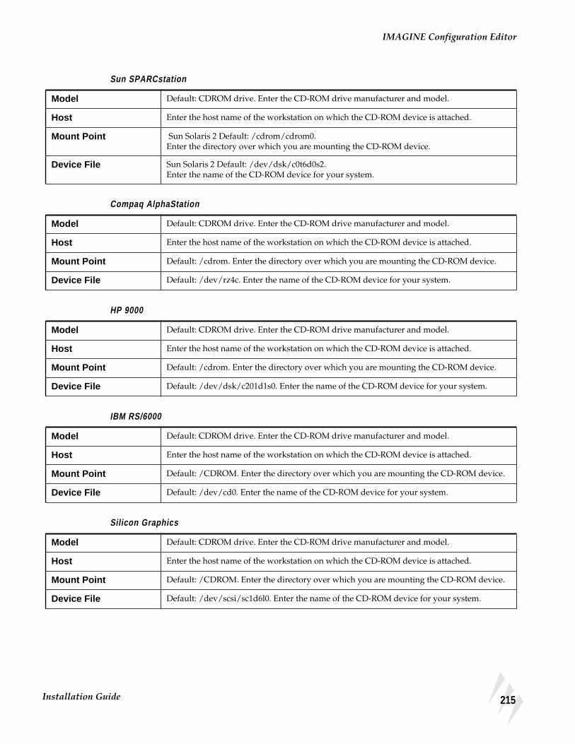
IMAGINE Configuration Editor
Sun SPARCstation
Compaq AlphaStation
HP 9000
IBM RS/6000
Silicon Graphics
Model Default: CDROM drive. Enter the CD-ROM drive manufacturer and model.
Host Enter the host name of the workstation on which the CD-ROM device is attached.
Mount Point Sun Solaris 2 Default: /cdrom/cdrom0.Enter the directory over which you are mounting the CD-ROM device.
Device File Sun Solaris 2 Default: /dev/dsk/c0t6d0s2.Enter the name of the CD-ROM device for your system.
Model Default: CDROM drive. Enter the CD-ROM drive manufacturer and model.
Host Enter the host name of the workstation on which the CD-ROM device is attached.
Mount Point Default: /cdrom. Enter the directory over which you are mounting the CD-ROM device.
Device File Default: /dev/rz4c. Enter the name of the CD-ROM device for your system.
Model Default: CDROM drive. Enter the CD-ROM drive manufacturer and model.
Host Enter the host name of the workstation on which the CD-ROM device is attached.
Mount Point Default: /cdrom. Enter the directory over which you are mounting the CD-ROM device.
Device File Default: /dev/dsk/c201d1s0. Enter the name of the CD-ROM device for your system.
Model Default: CDROM drive. Enter the CD-ROM drive manufacturer and model.
Host Enter the host name of the workstation on which the CD-ROM device is attached.
Mount Point Default: /CDROM. Enter the directory over which you are mounting the CD-ROM device.
Device File Default: /dev/cd0. Enter the name of the CD-ROM device for your system.
Model Default: CDROM drive. Enter the CD-ROM drive manufacturer and model.
Host Enter the host name of the workstation on which the CD-ROM device is attached.
Mount Point Default: /CDROM. Enter the directory over which you are mounting the CD-ROM device.
Device File Default: /dev/scsi/sc1d6l0. Enter the name of the CD-ROM device for your system.
215Installation Guide

CD-ROM Device
Enable AutomaticMounting of CD-ROM Device
Silicon Graphics
Silicon Graphics has its own CD-ROM mounting program, mediad. Therefore if yoursystem has mediad enabled, the CD-ROM is mounted automatically as soon as youinsert a CD-ROM. If the removable media daemon, mediad, is not being, used you canmount the CD manually.
The ERDAS IMAGINE program cdromctl needs to be there as a null driver. It is calledby the Import/Export programs.
Sun SPARCstation, Solaris Only
Solaris has its own CD-ROM mounting program, vold. Therefore, if your system hasthe vold daemon enabled, the CD-ROM is mounted automatically as soon as youinsert a CD-ROM. If volume management, vold, is not being used, you can mount theCD manually.
The ERDAS IMAGINE program, cdromctl, needs to be there as a null driver. It is calledby the Import/Export programs.
All Other Workstations
ERDAS IMAGINE comes with a utility program, called cdromctl, that is used toautomatically mount CD-ROM devices as needed to access data on a CD-ROM. Thisprogram also is used to unmount the CD-ROM device when access to the data is nolonger required. This relieves the user from having to mount the CD-ROM devicemanually.
CD-ROM devices that have been mounted manually by the user are unmounted by theautomatic CD-ROM mounting facility after ERDAS IMAGINE has finished accessingthe data on that device.
The automatic CD-ROM mounting facility cannot be used to automatically mount andaccess CD-ROM devices on remote hosts.
216 ERDAS IMAGINE

Enable Automatic Mounting of CD-ROM Device
cdromctl Program The cdromctl program can work only if it is run with root user authority. Because thetypical ERDAS IMAGINE user does not have root user authority, the setup_systemscript attempts to give the cdromctl program root user authority in the<IMAGINE_HOME>/bin/<ARCH> directory during the installation process andwhen additional ERDAS IMAGINE systems are set up from an existing ERDASIMAGINE installation.
The setup_system script attempts to do this by changing the owner of the cdromctlprogram to root, and then changing the file permissions on the cdromctl file so thatthe set-user-ID-on-execution bit is set.
Silicon Graphics
1. Enter the following commands to add the CD-ROM device to /etc/fsd_auto. Thisautomatically mounts the CD-ROM device when the CD is entered.
# /usr/etc/mediad -p /<device name> /<mountpoint>
Replace <device name> with the name of the CD-ROM device for your system, forexample, /dev/scsi/sc0d4l0. Replace <mount point> with the name of the directoryover which you are mounting the CD-ROM device, for example /cdrom.
2. To start the mediad daemon, use the following command:
# /usr/etc/mediad -a
The CD-ROM device is now mounted and ready for the data to be unloaded or loaded.The mediad daemon starts automatically at boot time from now on.
All Other Workstations
The process of granting root user authority to the cdromctl program can fail for severalreasons. If you find this process has failed on your system during the installation orwhile running the setup_system script from an existing ERDAS IMAGINE installation,the following steps can be performed on that system to enable the automatic CD-ROMmounting facility:
1. Log in as root .
2. Enter the following:
cp <IMAGINE_HOME>/bin/<system architecture>/cdromctl <new location>
<IMAGINE_HOME> refers to the directory where IMAGINE software resides (e.g.,/usr/imagine/840).
<new location> refers to the new location for the cdromctl program. This location mustbe in a directory that resides in a file system that is mounted from a local disk (i.e., itshould not be somewhere in an NFS mounted file system).
217Installation Guide

CD-ROM Device
3. Enter the following:
chown root <new location>/cdromctl
4. Then enter:
chmod 4555 <new location>/cdromctl
5. Log in as the ERDAS IMAGINE system administrator and create a Global configurationfor this host that has a CDROMCTL preference value equal to:
<new location>/cdromctl
See "CHAPTER 19: Host System"for more information on the CDROMCTL preference.
Manual Mounting ofCD-ROM Device
Perform the following steps to manually mount a CD-ROM device.
Note: If you are configuring on a Compaq AlphaStation, your system must be configuredto read the ISO 9660 or High Sierra CD-ROM format.
1. Log in as root .
2. Make the directory over which you are mounting the CD-ROM device, if it does notalready exist.
# mkdir /<mount point>
Replace <mount point> with the name of the directory over which you are mountingthe CD-ROM device, for example /cdrom.
3. Enter the following commands to mount the CD-ROM device:
Silicon Graphics
# mount -rt iso9660 <device name>/<mount point>
Replace <device name> with the name of the CD-ROM device for your system, forexample, /dev/scsi/sc1d6l0. Replace <mount point> with the name of the directoryover which you are mounting the CD-ROM device, for example, /cdrom. This is anexample of the mount command:
# mount -rt iso9660 /dev/scsi/sc1d6l0 /cdrom
IBM RS/6000
# mount -o ro -v cdrfs <device name> /<mount point>
218 ERDAS IMAGINE

Remote CD-ROM Access
Replace <device name> with the name of the CD-ROM device for your system. Forexample, /dev/cd0. Replace <mount point> with the name of the directory over whichyou are mounting the CD-ROM device, for example /cdrom. This is an example of themount command:
# mount -o ro -v cdrfs /dev/cd0 /cdrom
HP 9000
HPUX 11.00
# mount -r -F cdfs <device name> <mount point>
Replace <device name> with the name of the CD-ROM device for your system. Forexample, /dev/dsk/c1t2d0. Replace <mount point> with the name of the directoryover which you are mounting the CD-ROM device. For example, /cdrom. This is anexample of the mount command:
# mount -r -F cdfs /dev/dsk/c1t2d0 /cdrom
Compaq AlphaStation
# mount -r -t cdfs -o noversion <device name> <mount point>
Replace <device name> with the name of the CD-ROM device for your system. Forexample, /dev/dsk/c1t2d0. Replace <mount point> with the name of the directoryover which you are mounting the CD-ROM device. For example, /cdrom. This is anexample of the mount command:
# mount -r -t cdfs -o noversion /dev/rz4c /cdrom
Sun SPARCstation
Sun Solaris 2
# mount -r -F hsfs <device name> <mount point>
Replace <device name> with the name of the CD-ROM device for your system. Forexample, /dev/c0t6d0s2. Replace <mount point> with the name of the directory overwhich you are mounting the CD-ROM device. For example /cdrom or/cdrom/cdrom0. This is an example of the mount command:
# mount -r -F hsfs /dev/c0t6d0s2 /cdrom/cdrom0
The CD-ROM device is now mounted and ready for the data to be unloaded or loaded.
Remote CD-ROMAccess
In order to access a CD-ROM device across a network, you need to use the IMAGINEConfiguration Editor to configure the remote CD-ROM device, then you have to NFSmount the remote CD-ROM file system with a local NFS mount point. This mountpoint must be identical to the remote CD-ROM mount point. Perform the followingsteps to complete this process:
219Installation Guide

CD-ROM Device
The remote workstation refers to the workstation to which the CD-ROM device isattached. The local workstation refers to the workstation where you are currentlyrunning ERDAS IMAGINE software.
1. Follow the instructions in the ERDAS IMAGINE Configuration Editor section toconfigure a CD-ROM device for the remote workstation.
NOTE: You may do this by running ERDAS IMAGINE and accessing the ConfigurationEditor on the local workstation, if you like. However, be sure that you set the Host preferenceto the remote workstation host name.
Log In as Root For the remaining instructions, you will most likely need to be the root user on boththe remote and local workstations. Replace <mount point> with the value you enteredfor the Mount Point preference when you configured the remote CD-ROM device instep 1.
2. Use the following command on the remote system (where the CD-ROM is connected)to create the <remote mount point> directory if it does not already exist:
# mkdir <remote mount point>
Mount the CD-ROM
3. Use the following command on the remote system to mount the CD-ROM.
Silicon Graphics
# mount -rt iso9660 <device name> <mount point>
Replace <device name> with the name of the CD-ROM device for your system. Forexample, /dev/scsi/sc1d6l0.
IBM RS/6000
# mount -o ro -v cdrfs <device name> <mount point>
Replace <device name> with the name of the CD-ROM device for your system. Forexample, /dev/cd0.
HP 9000
HPUX 10.11
# mount -r -F cdfs <device name> <mount point>
Replace <device name> with the name of the CD-ROM device for your system. Forexample, /dev/dsk/c1t2d0.
Compaq AlphaStation
# mount -r -t cdfs -o noversion <device name> <mount point>
Replace <device name> with the name of the CD-ROM device for your system. Forexample, /dev/rz4c.
220 ERDAS IMAGINE

Remote CD-ROM Access
Sun SPARCstation
Sun Solaris 2
# mount -r -F hsfs <device name> <mount point>
Replace <device name> with the name of the CD-ROM device for your system. Forexample, /dev/sr0 or /dev/c0t6d0s2.
Export to Network
4. Edit the /etc/exports file (/etc/dfs/dfstab under Solaris 2.X) on the remote system toadd the <mount point> directory with read-only permission as in the examples below:
Compaq AlphaStation
/cdrom -ro
HP 9000
/cdrom -ro
IBM RS/6000
/cdrom -ro
Silicon Graphics
/cdrom -ro
Silicon Graphics with mediad
/CDROM -ro
Sun SPARCstation
Sun Solaris 2.6 or 2.7
share -F nfs -o ro /cdrom
Sun Solaris 2.6 or 2.7 with vold
share -F nfs -o ro /cdrom/imagine840_u
If the /etc/exports or /etc/dfs/dfstab file was not already on this system, then youneed to reboot the system.
5. Use the following command on the remote system to export the <remote mount point>directory to your network.
Silicon Graphics
# /usr/etc/ exportfs -a
221Installation Guide

CD-ROM Device
HP 9000
HPUX 10.11
# /usr/sbin/exportfs -a
Sun SPARCstation
Sun Solaris 2
# /usr/sbin/ shareall
6. On the local system (the system where you are running ERDAS IMAGINE) you need tocreate the <mount point> directory if it does not already exist:
# mkdir <mount point>
7. Use the following command on the local system to mount the CD-ROM from the remoteworkstation.
# mount <remote machine hostname>:<remote mount point> <mount point>
Unmount the CD-ROM(HP 9000 only)
When finished using the CD, use the following command on the local system tounmount the CD-ROM from the remote workstation:
# unmount <mount point>
222 ERDAS IMAGINE

CHAPTER 21Tape Drive
Description This chapter explains how to set up a tape drive so that it can be accessed by ERDASIMAGINE programs and utilities.
Operator Expertise
The system setup needs to be performed by a system manager who is familiar with thetape drive, the appropriate workstation, and their corresponding documentation.
IMAGINEConfiguration Editor
You need to use the IMAGINE Configuration Editor to define the tape drive withinERDAS IMAGINE and set up preferences.
1. Select Session | Configuration from the ERDAS IMAGINE icon panel menu to openthe Configuration Editor. The Configuration Editor opens.
2. Click on the Configuration Class popup list and select tapes .
You need to save any additions or changes made to the Configuration Editor before youchange to a different configuration class. Select File | Save to save the setup andpreferences for the current configuration class.
3. Ensure that the Use Filter check box is on.
4. Click on the Template Filter popup list. A list of tape devices that have been configuredwith the tape filter is displayed. Select tape .
5. Under Database Level , click on the Directory popup list and select one of thefollowing options:
Global = <IMAGINE_HOME>/etcThe setup and preferences for the current device are accessible by all ERDASIMAGINE users working from the same IMAGINE installation. You cannot save to theglobal environment unless you are the system administrator who installed ERDASIMAGINE software.
To prevent the administrator's User preferences from being inadvertently saved to theglobal database, only the global configuration information is accessible from the rest ofthe ERDAS IMAGINE user interface for this Configuration Class when the Globaloption is selected. This allows a system administrator to properly test only the globalchanges.
223Installation Guide

Tape Drive
User = <HOME>/.imagine840The setup and preferences for the current device are accessible only by you (wheneveryou are logged into the same account). Your User preference changes to a globallyconfigured device that takes precedence over the Global preference settings for yourERDAS IMAGINE sessions.
NOTE: The changes you have made in the Configuration Editor take effect immediately in thecurrent ERDAS IMAGINE session. They are also retained for the current ERDAS IMAGINEsession even if they have not been saved. This allows Global changes to be tested in the currentERDAS IMAGINE session without affecting users sharing the same installation of ERDASIMAGINE.
If all of your User preferences do not appear to be reflected in the ERDAS IMAGINE userinterface, verify that the User option is selected in the Directory popup list for the appropriateConfiguration Class(es) in the Configuration Editor.
The File label shows you the file name that is used when you save the setup andpreferences for the current configuration class.
6. Click the New button to add a new tape drive using the tape template filter. The Createnew device dialog opens.
7. Enter any name for the device (e.g., tape:/dev/rst1). After you enter the name, press theReturn key on your keyboard for the name to be accepted, then click OK in the Createnew device dialog. This is the name that displays in the ERDAS IMAGINE dialogs asan output device option.
Set Up Preferences The Configuration Editor enables you to set parameters for the currently selected tapedrive. The following sections list the default entries for the tape drive.
Silicon Graphics
Begin by following these steps in the command shell to set up a tape drive device filefor the SGI:
1. Log on as Root.
2. cd /dev
3. rm *tape
4. ./MAKEDEV tape tapelinks
This creates two files, two of which are /dev/tape and /dev/nrtape (the defaultpreference).
Tape Model Default: 1/2 inch mag tape. Enter the type of tape drive.
Host Enter the host name of the workstation to which the tape drive is attached.
Tape drive device file Example: /dev/nrtape. Enter the name of the tape drive device file for the tape drive.
224 ERDAS IMAGINE

IMAGINE Configuration Editor
IBM RS/6000
HP 9000
Compaq AlphaStation
Sun SPARCstation
Tape Model Default: 1/2 inch mag tape. Enter the type of tape drive.
Host Enter the host name of the workstation to which the tape drive is attached.
Tape drive device file Default: /dev/rmt0. Enter the name of the tape drive device file for the tape drive.
Tape Model Default: 1/2 inch mag tape. Enter the type of tape drive.
Host Enter the host name of the workstation to which the tape drive is attached.
Tape drive device file Default: /dev/rmt/c201d3mnb. Enter the name of the tape drive device file for the tape drive.
Tape Model Default: 4 mm tape. Enter the type of tape drive.
Host Enter the host name of the workstation to which the tape drive is attached.
Tape drive device file Default: /dev/rmt0h. Enter the name of the tape drive device file for the tape drive.
Tape Model Default: 1/2 inch mag tape. Enter the type of tape drive.
Host Enter the host name of the workstation to which the tape drive is attached.
Tape drive device file Sun, Solaris 2.6 or 2.7 Default: /dev/rmt/0b.Enter the name of the tape drive device file for the tape drive.
225Installation Guide

Tape Drive
Remote Tape Access The IMAGINE Configuration Editor enables you to access a tape drive across anetwork. The following steps must be performed before you can load data to or froma remote tape drive.
The remote workstation refers to the workstation to which the tape drive is attached.The local workstation refers to the workstation where you are currently runningERDAS IMAGINE software.
The term “ERDAS IMAGINE software” in the following discussion must include atleast the architecture-specific IMAGINE Essentials fileset for the architecture of thelocal workstation, and either the architecture-specific IMAGINE Essentials fileset forthe architecture of the remote workstation OR the architecture-specific IMAGINERemote Services fileset for the architecture of the remote workstation. See "CHAPTER23: Remote Services"for more details about loading this fileset.
Automatic Tape Server Start-up at Time of Access
1. In order to have the remote tape server started automatically to allow remote accesswithin ERDAS IMAGINE, ERDAS IMAGINE software must be accessible from thesame directory on both the local and remote workstations. For example, if ERDASIMAGINE software resides in the /usr/imagine/840 directory on the localworkstation, the software must either be installed in or NFS-mounted on the/usr/imagine/840 directory on the remote workstation.
2. The name of the local workstation must exist in the <HOME>/.rhosts file on the remoteworkstation. <HOME> represents the home directory of any ERDAS IMAGINE userthat wishes to access the remote tape drive. Be sure that the permissions on the<HOME>/.rhosts file allow writing only by the user.
Proceed to "Set Up Tape Drive" on page 227.
Automatic Tape Server Start-up at Time of System Boot
1. In order to have the tape server started on a remote workstation every time the remotesystem boots, ERDAS IMAGINE software must either be installed on the remoteworkstation or it must be NFS-mounted at boot time. ERDAS IMAGINE software doesnot necessarily have to be accessible on the remote workstation from the same directoryas the local workstation.
2. The tape server must be invoked from a system start-up script (e.g., /etc/rc.local onSolaris systems) at boot time on the remote workstation with the following command:
<IMAGINE_HOME>/bin/emta_start
Replace <IMAGINE_HOME> with the directory through which ERDAS IMAGINEsoftware is accessible on the remote workstation. The change to the system start-upscripts generally requires root user authority.
Proceed to "Set Up Tape Drive" on page 227.
226 ERDAS IMAGINE

Remote Tape Access
Set Up Tape Drive Use the Configuration Editor to set up and configure the tape drive for the remoteworkstation.
NOTE: The configuration can be performed from either the local or remote workstation.
227Installation Guide

Tape Drive
228 ERDAS IMAGINE

CHAPTER 22Tablet DigitizersAltek Series Model AC32 Moveable MenuAltek Series Model 33240 TabletCalComp 9100 and 9500 SeriesCalComp Drawing Board II and IIIGTCO Accutab Series Custom Configuration MenuGTCO DIGI-PAD Series
Description This chapter explains how to set up a digitizing tablet so that it can be accessed byERDAS IMAGINE programs and utilities. These instructions are not included withany hardware.
Operator Expertise
The system setup and configuration need to be performed by a system manager whois familiar with the tablet, the Workstation you are using, and their documentation.
Select a Serial Line
Silicon Graphics
Most Silicon Graphics computers have at least two serial lines, called /dev/ttyd1 and/dev/ttyd2. These may have other names, according to the setup of your system.
IBM RS/6000
Most IBM RS/6000 workstations have at least two serial lines, called /dev/tty0 and/dev/tty1. These may have other names, according to the setup of your system.
HP 9000Compaq AlphaStation
Most HP 9000 workstations and Compaq AlphaStations have at least two serial lines,called /dev/tty00 and /dev/tty01. These may have other names, according to thesetup of your system.
229Installation Guide

Tablet Digitizers
Sun SPARCstation
Most Sun SPARCstations have at least two serial lines, called /dev/ttya and/dev/ttyb. These may have other names, according to the setup of your system. In thisdocumentation, replace <serial line> with the name of the serial line you are using.
NOTE: Each of these serial lines can be used as a login port for a terminal. Select a serial linethat you can dedicate permanently to the digitizing tablet, rather than use the line as a loginport.
Disable Login Line
Silicon Graphics
1. Log in to the root account.
In order to properly install the digitizer, you must have access to the root account (i.e.,know the root password).
2. Make a backup copy of the file /etc/inittab with the cp command.
This backup ensures that you can recover from any mistakes you might make to thisfile.
3. Use a text editor to edit the /etc/inittab file.
It looks similar to the example below:
If the status is respawn for the serial line (e.g., ttyd1 or ttyd2) that you want to dedicateto the digitizing tablet, you must change the status to off .
When the status is respawn for any device line, then the line for that device can beused as a login line. The line for a serial device, such as the digitizing tablet, must bedisabled as a login line.
Save the file /etc/inittab with the change.
4. Reboot the workstation.
IBM RS/6000
1. Login to the root account.
In order to properly install the digitizer, you must have access to the root account (i.e.,know the root password).
tp:23:respawn:/etc/getty tport co_9600# textportt1:23:respawn:/etc/getty ttyd1 co_9600# alt consolet2:23:off:/etc/getty -N ttyd2 co_9600 # port 2
230 ERDAS IMAGINE

Disable Login Line
2. Use the following command to change a tty line:
# smit chgtty
If the following message displays:
There are no items of this type
then you must create a tty line by using the following command:
# smit maktty
3. The Enable Login field must read disable .
HP 9000
1. Log in to the root account.
In order to properly install the digitizer, you must have access to the root account (i.e.,know the root password).
2. Make a backup copy of the file /etc/inittab with the cp command.
This backup ensures that you can recover from any mistakes you might make to thisfile. We are using /dev/tty0p0 as an example.
3. Use a text editor to edit the /etc/inittab file. It looks similar to the example below:
a0:3:respawn:/etc/getty -h tty0p0 9600
If the respawn value is on for the serial line (e.g., tty0p0 or tty0p1) that you want todedicate to the digitizing tablet, you must change the status to off .
When the status is on for any device line, then the line for that device can be used as alogin line. The line for a serial device, such as the digitizing tablet, must be disabled asa login line. The file should be similar to the example below:
a0:3:off:/etc/getty -h tty0p0 9600
4. Save the file /etc/inittab with the change.
5. Reboot the system to invoke the change.
Sun SPARCstation
Sun Solaris
1. Log in to the root account.
In order to properly install the digitizer, you must have access to the root account (i.e.,know the root password).
231Installation Guide

Tablet Digitizers
2. List the services and look for your port, e.g., ttya (/dev/term/a).
# pmadm -l
The listing looks similar to the example below. (The lines are actually longer thanshown here.)
3. Disable the login service.
# pmadm -d -p <PMTAG> -s <SVCTAG>
For example, the entry based on the listing above would read:
# pmadm -d -p zsmon -s ttya
4. To check to see that the line is disabled, you can repeat step 2. and the FLGS columnshould read ux .
PMTAG PMTYPE SVCTAG FLGS ID <PMSPECIFIC>tcp listen lp - root - - p - /var/spool/lp/fifos/listens5 #tcp listen lpd - root \x00020203000000000000000000000000 - p - /var/spooltcp listen 0 - root \x00020ACE000000000000000000000000 - c - /usr/lib/szsmon ttymon ttya u root /dev/term/a I - /usr/bin/login - 9600 ldterm,ttcompzsmon ttymon ttyb u root /dev/term/b I - /usr/bin/login - 9600 ldterm,ttcomp
232 ERDAS IMAGINE

Set Protection
Connect Digitizer The proper RS232 cable is required to connect the digitizer to the workstation. Belowis a list of the connections that need to be made between two 25-pin ports. The cablethat you use varies depending upon the genders of the ports.
IBM RS/6000Compaq AlphaStation
It is very important to note that pin 2 and pin 3 do not swap with each other.
SunHP 9000Silicon Graphics
Set Protection Set the protection on the serial line with the chmod command. This allows ERDASIMAGINE software to access the line. Enter the name of your platform’s serial line inplace of <serial line> below.
NOTE: You must be logged into the root account to use this command.
# chmod a+rw /dev/<serial line>
Workstation End Digitizer End
pin 1 pin 1
pin 2 pin 2
pin 3 pin 3
pin 7 pin 7
Workstation End Digitizer End
pin 1 pin 1
pin 2 pin 3
pin 3 pin 2
pin 7 pin 7
233Installation Guide

Tablet Digitizers
Test the Line Follow the steps below to test the serial line with the digitizing tablet. The instructionsare platform-specific.
HP 9000Silicon Graphics
1. To test the serial line with the digitizing tablet, you can use the cat command with thedevice name as the argument, for example:
# cat /dev/tty0p0
In the above example, the device is connected to the /dev/tty0p0 port.
2. Now use the controls on the digitizer keypad. Coordinates that represent the locationof the cursor should display in the shell window where you used the cat command.
If no text displays, retrace your steps carefully according to the instructions above.Make sure that cables are plugged in securely.
To exit the cat command, type CTRL-C.
IBM RS/6000
1. To test the serial line, you can use the appropriate tip command to see thecommunication between the digitizing tablet and the workstation echoed on the shellwindow.
2. Add this line to the file /etc/remote. (This file is read when tip is used. It gives thedigitizing tablet a name and specifies the baud rate.)
NOTE: If the remote file does not exist, you need to create it.
<tablet>:dv=/dev/tty0:br#9600
In this example, /dev/tty0 is the serial line used, <tablet> is the name of the digitizingtablet, and 9600 is the baud rate.
Save the file /etc/remote with this change.
Compaq AlphaStation
1. To test the serial line, you can use the appropriate tip command to see thecommunication between the digitizing tablet and the workstation echoed on the shellwindow.
2. Add this line to the file /etc/remote. (This file is read when tip is used. It gives thedigitizing tablet a name and specifies the baud rate.)
NOTE: If the remote file does not exist, you need to create it.
<tablet>:dv=/dev/tty00:br#9600
234 ERDAS IMAGINE

Test the Line
In this example, /dev/tty00 is the serial line used, <tablet> is the name of the digitizingtablet, and 9600 is the baud rate.
Save the file /etc/remote with this change.
Sun SPARCstation
1. To test the serial line, you can use the appropriate tip command to see thecommunication between the digitizing tablet and the workstation echoed on the shellwindow.
2. Add this line to the file /etc/remote. (This file is read when tip is used. It gives thedigitizing tablet a name and specifies the baud rate.)
NOTE: If the remote file does not exist, you need to create it.
<tablet>:dv=/dev/ttya:br#9600
In this example, /dev/ttya is the serial line used, <tablet> is the name of the digitizingtablet, and 9600 is the baud rate.
Save the file /etc/remote with the change you have made.
3. Enter this command at the prompt to test the tablet connection:
# tip <tablet>
Replace <tablet> with the name you specified for the digitizing tablet in the file/etc/remote.
4. Now use the controls on the digitizer keypad. Coordinates that represent the locationof the cursor should display in the shell window where you used the tip command.
If no text displays, retrace your steps carefully according to the instructions above.Make sure that cables are plugged in securely.
To disable tip and stop the text from displaying, enter a tilde and a period at thekeyboard:
~.
235Installation Guide

Tablet Digitizers
Switch Settings andFormats
When you are using ERDAS IMAGINE with the supported digitizers, we recommendthe specified switch settings and data formats.
Altek Series ModelAC32Moveable Menu
aThis format corresponds with the ALTEK format number 4.
Serial Speed 9600 bps
Serial Misc. 1 stop bit / 8 data bits / No parity
Emulation ALTEK
Format F12 a F XXXXX YYYYY
Rate 50 pts/sec
Resolution .001 inch
Run Type Type 1
Mode Point
Miscellany CR on / LF on / CTS off
236 ERDAS IMAGINE

Switch Settings and Formats
Altek Series Model 33240Tablet
Switch Settings for the Left Bank
Switch Settings for the Right Bank
*Format 4 is the default and ERDAS IMAGINE does not support format 6. You may needto use a swap cable.
IMAGINEFormat
Switch 1 Switch 2 Switch 3 Switch 4 Switch 5 Switch 6 Switch 7 Switch 8
1 on off on on on on on off
2 on off on on on on on off
3 on off on on on on on off
4* on off on on on on on off
5 on off on on on on on off
6 on off on on on on on off
7 on off on on on on on off
IMAGINEFormat
Switch 1 Switch 2 Switch 3 Switch 4 Switch 5 Switch 6 Switch 7 Switch 8
1 on off off off on on on on
2 on off off off on on on off
3 on off off off on on off on
4* on off off off on on off off
5 on off off off on off on on
6 on off off off on off on off
7 on off off off on off off on
237Installation Guide

Tablet Digitizers
CalComp 9100 Series
Switch Settings for SB1
aThese settings are set at the factory and should not be changed.
*Format 4 is the default.
Switch Settings for SW1
Switch Settings for SW2
IMAGINEFormat
Switch 1 Switch 2 Switch 3Switch
4* Switch 5 Switch 6Switch
7aSwitch
8a
1 close open close close close close close open
2 close open close open close close close open
3 close open open close close close close open
4 close open open open close close close open
SW1Switch 1
SW1Switch 2
SW1Switch 3
SW1Switch 4
SW1Switch 5
SW1Switch 6
SW1Switch 7
SW1Switch 8
AllIMAGINEFormats
open open close close open close close open
SW2Switch 1
SW2Switch 2
SW2Switch 3
SW2Switch 4
SW2Switch 5
SW2Switch 6
SW2Switch 7
SW2Switch 8
AllIMAGINEFormats
close open close open close close close close
238 ERDAS IMAGINE

Switch Settings and Formats
CalComp 9500 Series
Operating Mode and Resolution Switch Settings for Area 1
Soft Switch Settings for Area 1
*Format 4 is the default.
Switch Settings for Area 2 (Port A) Only
The switch settings for CalComp 9500 areas 3 (Port B), 4, and 5 are not applicable.
Operating Mode SwitchResolution(1000 LPI)
Switch
Point on 1 off
Run off 2 on
Track off 3 on
Line off
INC off
Prompt off
IMAGINEFormat
Switch 1 Switch 2 Switch 3 Switch 4 Switch 5
1 off off on off off
2 off off on off on
3 off off on on off
4* off off on on on
Baud Rate(9600)
SwitchDataBits
SwitchParity(none)
Switch Stop Bit Switch
1 off 7 off 1 on Stop 1 off
2 off 8 on 2 off Stop 2 off
3 on 3 off
Transmit/Receive
SwitchLineFeed
Switch Port A Switch Echo Switch
TX 2/3 on LF off Port on Echo Off
239Installation Guide
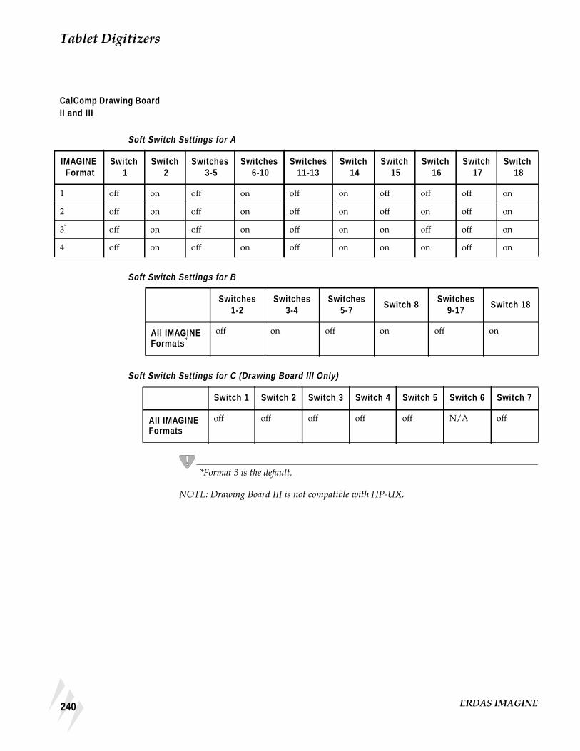
Tablet Digitizers
CalComp Drawing BoardII and III
Soft Switch Settings for A
Soft Switch Settings for B
Soft Switch Settings for C (Drawing Board III Only)
*Format 3 is the default.
NOTE: Drawing Board III is not compatible with HP-UX.
IMAGINE Format
Switch 1
Switch 2
Switches 3-5
Switches 6-10
Switches11-13
Switch 14
Switch 15
Switch 16
Switch 17
Switch 18
1 off on off on off on off off off on
2 off on off on off on off on off on
3* off on off on off on on off off on
4 off on off on off on on on off on
Switches1-2
Switches3-4
Switches5-7
Switch 8Switches
9-17Switch 18
All IMAGINEFormats *
off on off on off on
Switch 1 Switch 2 Switch 3 Switch 4 Switch 5 Switch 6 Switch 7
All IMAGINEFormats
off off off off off N/A off
240 ERDAS IMAGINE
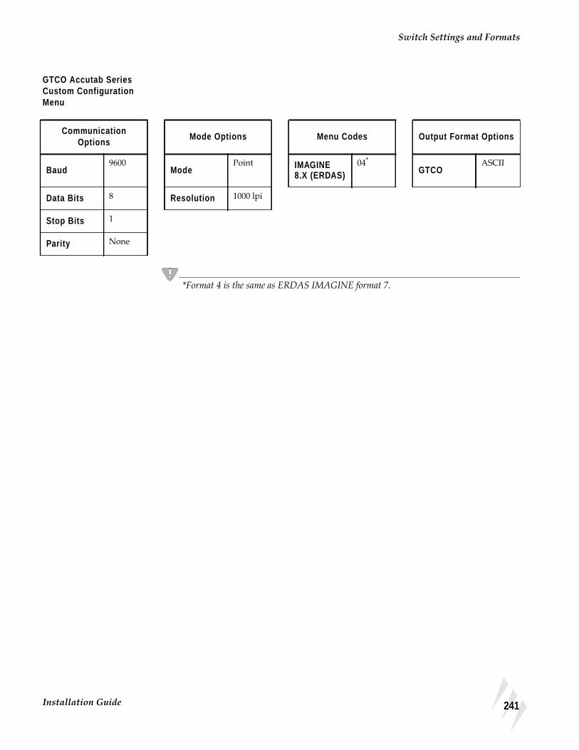
Switch Settings and Formats
GTCO Accutab SeriesCustom ConfigurationMenu
*Format 4 is the same as ERDAS IMAGINE format 7.
CommunicationOptions
Mode Options Menu Codes Output Format Options
Baud9600
ModePoint IMAGINE
8.X (ERDAS)04*
GTCOASCII
Data Bits 8 Resolution 1000 lpi
Stop Bits 1
Parity None
241Installation Guide
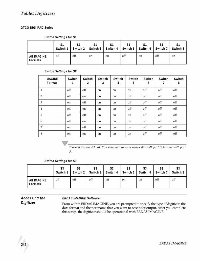
Tablet Digitizers
GTCO DIGI-PAD Series
Switch Settings for S1
Switch Settings for S2
*Format 7 is the default. You may need to use a swap cable with port B, but not with portA.
Switch Settings for S3
Accessing theDigitizer
ERDAS IMAGINE Software
From within ERDAS IMAGINE, you are prompted to specify the type of digitizer, thedata format and the port name that you want to access for output. After you completethis setup, the digitizer should be operational with ERDAS IMAGINE.
S1Switch 1
S1Switch 2
S1Switch 3
S1Switch 4
S1Switch 5
S1Switch 6
S1Switch 7
S1Switch 8
All IMAGINEFormats
off off on on off off off on
IMAGINEFormat
Switch1
Switch2
Switch3
Switch4
Switch5
Switch6
Switch7
Switch8
1 off off on on off off off off
2 off on on on off off off off
3 on off on on off off off off
4 on on on on off off off off
5 off off on on on off off off
6 off on on on on off off off
7* on off on on on off off off
8 on on on on on off off off
S3Switch 1
S3Switch 2
S3Switch 3
S3Switch 4
S3Switch 5
S3Switch 6
S3Switch 7
S3Switch 8
All IMAGINEFormats
off off off off on off off off
242 ERDAS IMAGINE

Accessing the Digitizer
See the ERDAS IMAGINE On-Line Help for more information on setting up the digitizerwithin ERDAS IMAGINE.
243Installation Guide

Tablet Digitizers
244 ERDAS IMAGINE

CHAPTER 23Remote Services
Description The IMAGINE Remote Services module is a collection of architecture specific filesets,each of which contains the minimal amount of software required to run the IMAGINElicense broker, the IMAGINE tape server, and any of the IMAGINE print filters on ahost of that architecture without having to load the architecture specific IMAGINEEssentials fileset for that architecture.
The IMAGINE Remote Services module must be installed in an existing ERDASIMAGINE installation directory. The filesets for each architecture supported byERDAS IMAGINE are on the installation CD and may be installed when the ERDASIMAGINE software is installed or at a later time.
Refer to "CHAPTER 20: CD-ROM Device"for instructions on installing modules fromthe IMAGINE installation CD.
If the IMAGINE Essentials module for an architecture has already been installed, theRemote Services module should not be installed.
Remote Tape Accessvia IMAGINE RemoteServices
As long as the IMAGINE Remote Services module for the architecture of the remotetape host has been properly installed and the installation of ERDAS IMAGINE isaccessible from the remote tape host, the instructions in the "CHAPTER 21: TapeDrive"may be followed as is.
245Installation Guide

Remote Services
Remote PrinterAccess via IMAGINERemote Services
The IMAGINE Remote Services module may be used to print to a remote workstationof an architecture for which you have not installed the architecture specific IMAGINEEssentials fileset.
If you do not have the architecture specific IMAGINE Essentials fileset loaded for thearchitecture of the remote workstation, you are not able to run ERDAS IMAGINE onthe remote workstation. However, you may still access a printer attached to the remoteworkstation. You have to use ERDAS IMAGINE on the workstation from which youwish to print (the local workstation) to configure a printer for the remote workstation,and then go to the remote workstation and create the appropriate print queue.
The remote printer that you are accessing must be attached to a platform that is supportedunder ERDAS IMAGINE V8.4, and the output device must be supported on thatplatform. For example, you could access a Kodak XL7700 printer attached to a remote SunSPARCstation, because ERDAS IMAGINE V8.4 runs on the Sun, and the KodakXL7700 is a supported output device for the Sun. However, you could not access aVersatec electrostatic plotter attached to a Compaq AlphaStation system, becausealthough the Compaq AlphaStation is a supported ERDAS IMAGINE V8.4 platform,ERDAS IMAGINE does not support the Versatec on the Compaq AlphaStation.
Contact your local sales office for information about which output devices are supportedon each platform.
Local Workstation Follow the instructions in the “IMAGINE Configuration Editor” section of theappropriate printer configuration chapter of this manual. Be sure that you use thename of the remote workstation for the Print Queue Host preference.
Remote Workstation The <IMAGINE_HOME>/bin/install_printer script helps you construct theappropriate shell script that, when run as the root user, creates a print queue that canbe used to serve ERDAS IMAGINE print requests to a specific printer.
1. Run the install_printer script.
# <IMAGINE_HOME>/bin/install_printer
The following prompts display:
2. Please enter the name of the IMAGINE printer: <name>
<name> should correspond to the name you entered in the “IMAGINEConfiguration Editor” section of the appropriate printer configuration chapter.
3. With what print queue name is '<name>' (going to be) configured? <queue>
<queue> should correspond to the Print Queue Name preference for printer <name>from the “Set Up Preferences” section of the appropriate printer configuration chapter.
4. On which host is this print queue (going to be) maintained? <host>
246 ERDAS IMAGINE
Remote Printer Access via IMAGINE Remote Services
<host> should correspond to the Print Queue Host preference for printer <name>from the “Set Up Preferences” section of the appropriate printer configuration chapter.
• For an HP DesignJet with the HP JetDirect Network Interface, <host> should bethe name of the host on which the network software is installed.
5. Which device is (going to be) acting as an interface to the printer? <device>
<device> should correspond to the Device preference for printer <name> from the“Set Up Preferences” section of the printer configuration chapter.
• For printers connected directly to the network, <device> should always be/dev/null .
6. On which printer template is this printer (going to be) configured? <tmplt>
<tmplt> should correspond to the value that was selected from the Template Filterpopup list in the “IMAGINE Configuration Editor” section of the appropriate printerconfiguration chapter.
7. Is the queue host running System V printing?
Your response depends on the system to which the printer is attached.
• For a printer host running AIX, Compaq Tru64 UNIX (4.0F), or UNIX, enter N.
• For a printer host running Sun Solaris 2 or HPUX enter Y.
• For a printer host running IRIX, your response depends on the options selectedwhen the system was set up. Enter N for BSD printing and Y for System V printing.
8. To which file would you like the script to be written? [/tmp/printcap] <file>
Specify the name of the script file to be created.
After you have finished answering the prompts of the install_printer script, youshould log into the system as the root user and run the script <file>. The remote hostis now ready to accept print requests.
Once you have an appropriate print queue on the remote workstation, you may simplyfollow the instructions under the “Local Workstation” subsection of the “RemotePrinter Access” section of the appropriate printer configuration chapter of this manualin order to make the printer on that remote workstation accessible to additionalERDAS IMAGINE workstations.
247Installation Guide

Remote Services
248 ERDAS IMAGINE

CHAPTER 24Configuring IMAGINE VirtualGIS for UNIX
SystemConfiguration
Compaq AlphaStation In order to make the best use of swap-space when running ERDAS IMAGINE, it isrecommended that Compaq AlphaStations be configured to use deferred swap-spacemode. By default, when Compaq Tru64 UNIX is installed, it is configured to useimmediate swap-space mode. For information on the swap-space modes underCompaq Tru64 UNIX (4.0F), type the following from a UNIX shell:
# man swapon
In order to change a system from immediate mode to deferred mode, you must loginas root, and rename the file /sbin/swapdefault, and then reboot:
# cd /sbin# mv swapdefault swapdefault.bak# reboot
Open 3D 4.5 or higher must be installed to use PowerStorm 4D40T, 4D50T, and 4D60Tgraphics cards successfully with IMAGINE VirtualGIS. Because there is a knownproblem displaying draped data with the 4.5 version, it is recommended that youdownload Open 3D 4.6 or higher, from the following web site:http://www.digital.com .
The following note is from Compaq AlphaStation’s release notes about Open 3D:
In order to improve performance, the PowerStorm 4D40T, 4D50T, and 4D60T systemmakes extensive use of shared memory to send information to the X windows server.Shared memory is used for the following types of data:
• X connections when using the DISPLAY:0
• OpenGL rendering contexts
• Texture map data
However, the system imposes a limit on the number of shared memory segments thata process can access concurrently and the total amount of shared memory the systemallows. At times, an X windows client may run up against this limit.
If this occurs, client applications display the following warning:
dxlib warning: server shmget failed
It may also display other errors from applications indicating that they are out ofmemory when using some of the above types of data.
249Installation Guide

Configuring IMAGINE VirtualGIS for UNIX
There are two system limits that affect how much shared memory can be used at atime. There is a system-wide limit of 128 shared memory handles. There is a per-process limit of 32 handles that may be attached at a time. The Open3D kit for thePowerStorm 4D40T, 4D50T, and 4D60T increases these values to 256 and 64respectively.
Compaq recommends that you configure the system with at least the limits describedin the following steps. This should be done when logged in as root :
1. Save the ipc subsystem parameters to a file using the following command:
sysconfigdb -l ipc > /tmp/ipc.config
2. Edit the saved ipc.config in /tmp/ipc.config and set the shared memory parameters tothe desired values.
shm-mni is the number of shared memory segments available on the system. shm-segis the number of shared memory segments available to any individual process. Theshm-seg value should be fairly high as the X server process needs to connect to mostshared memory segments. shm-max is the amount of shared memory available on thesystem. This needs to include the maximum amount of the above items you expect touse on this system.
3. Update ipc subsystem in sysconfigtab.
NOTE: For larger data sets, both the shm-mni and the shm-seg values should be set to 4096.
# sysconfigdb -f /tmp/ipc.config -u ipc
# sysconfigdb -l ipc
ipc:
shm-mni = 1024
shm-seg = 256
shm-max = 67108864
4. Save the vm subsystem parameters to a file using the following command:
# sysconfigdb -l vm > /tmp/vm.config
If this command gives an error indicating that there is no vm subsystem, create a filecalled /tmp/vm.config with the following contents:
vm:
vm-mapentries=1000000
Then issue the following command and go to step 6.
# sysconfigdb -f /tmp/vm.config -a vm
250 ERDAS IMAGINE
System Configuration
5. If there is an existing vm subsystem, then edit /tmp/vm.config and add the followingline:
vm-mapentries=1000000
If there is already an entry for vm-mapentries , add 1000000 to the current value. Thenissue the following command:
# sysconfigdb -f /tmp/vm.config -u vm
6. Reboot the machine. You can verify that the new parameter values are in effect byissuing the following commands:
# sysconfig -q ipc shm-mni | grep shm-mni
shm-mni = 1024
# sysconfig -q ipc shm-seg | grep shm-seg
shm-seg = 256
# sysconfig -q ipc shm-max | grep shm-max
shm-max = 67108864
NOTE: For larger data sets, both the shm-mni and the shm-seg values should be set to 4096.
NOTE: Each time Open3D is installed shm-mni is reset to 256, shm-seq is reset to 64, andshm-max is removed from the configuration.
These values must be updated manually after every installation of Open3D.
Silicon Graphics Before starting ERDAS IMAGINE, the following adjustments should be made to yoursystem to increase the number of files allowed open, and to increase the performanceof texture mapping.
1. In a command window, login as root .
2. Enter systune -i .
3. At the prompt, enter rlimit_nofile_cur = 300 .
NOTE: To view the current settings for the Lockable Graphix Menu, type gfx .
4. If using an IMPACT, Onyx, or O2 system, enter gfxlockablemem = 50 . If using anOctane system, enter gfxlockablemem_gt64 = 50 .
5. Enter quit to exit.
6. Reboot.
251Installation Guide

Configuring IMAGINE VirtualGIS for UNIX
StereoConfiguration forUNIX Platforms
Contact StereoGraphics for the specific cable needed to work with your system andgraphics card at http://www.StereoGraphics.com.
Only Full Screen Stereo requires setting Frame Offset in the Configuration Editor. Oneway to determine Frame Offset for your monitor is to divide the screen height inpixels in half, and add 20 to the total value.
For example, if your screen resolution is set to 1024 x 768:
Therefore, you would set your Frame Offset to 404.000.
Compaq AlphaStation Both stereo displays, Stereo in a Window and Full Screen Stereo, require Open 3D 4.6or higher. This can be installed from the Layered Products CD that comes with yoursystem.
A stereo graphics emitter, an emitter cable, and liquid crystal glasses are required toview both types of stereo display.
Stereo-In-A-Window
You need one of the following graphics cards to display Stereo In-A-Window:
• Powerstorm 4D40T
• 4D50T
• 4D60T
Follow these steps for stereo in-a-window configuration:
1. In a window terminal, login as root .
2. Edit text file /var/dt/Xservers by replacing the last line with::0 Local local@console /usr/bin/X11/X :0 -screen 1024x768 -I-estereo -vsync 110
3. Reboot the machine and relogin.
4. Start ERDAS IMAGINE.
5. Select Session | Configuration from the ERDAS IMAGINE icon panel menu bar.
6. Select Stereo Display from the Configuration Class popup list.
7. Select ALPHA from the Template Filter popup list.
8. Click the New button on the Configuration Editor.
9. Enter the name of the host machine and press Return .
10. Click OK to dismiss the dialog.
7682
--------- 20 404=+
252 ERDAS IMAGINE

Stereo Configuration for UNIX Platforms
11. Clear the text field next to Full Screen Stereo Command so it is empty.
12. Clear the text field next to Stereo In-A-Window Command so it is empty.
13. Clear the text field next to Exit Stereo so it is empty.
14. Select File | Save .
15. Close the Configuration Editor.
Full Screen Stereo
Full screen stereo is not supported on the Compaq AlphaStation platform:
253Installation Guide

Configuring IMAGINE VirtualGIS for UNIX
HP 9000 - HPUX 11.00. A stereo graphics emitter, an emitter cable, and liquid crystal glasses are required toview stereo display.
You need one of the following graphics cards to display stereo-in-a-window:
• VISUALIZE fx4
• fx6
NOTE: HP 9000-HPUX11.00 does not run full-screen stereo displays.
Stereo In-A-Window
Follow these steps for stereo-in-a-window display:
1. Open the Application Manager from the CDE icon panel.
2. Double-click the System Administrator icon from the Application Manager menudialog.
3. Double-click the Sam icon to open the System Administration Manager (SAM) dialog.
4. Enter the root password for your machine.
5. Double-click the Display icon in the SAM dialog.
6. Double-click the Monitor Configuration icon in the SAM dialog.
7. Click once to select the Monitor icon in the X Server Configuration dialog.
8. Select Actions | Modify Monitor Type from the X Server Configuration menu bar. TheModify Monitor Type dialog opens.
9. Select 1024x768, 98Hz, 8x16 Font, and Stereo in a Window from the list of possibleconfigurations.
10. Click the Test Monitor Type button.
NOTE: If the screen goes black, wait 15 seconds. The screen returns, and you can reselect themonitor type from the list.
11. Click OK to accept the changes and close the Modify Monitor Type dialog.
12. Click Yes to the two confirmation dialogs. The X Server restarts itself.
13. Relogin to your machine.
14. Start ERDAS IMAGINE.
15. Select Session | Configuration from the ERDAS IMAGINE icon panel menu bar.
16. Select Stereo Display from the Configuration Class popup list.
17. Select HPUX from the Template Filter popup list.
254 ERDAS IMAGINE

Stereo Configuration for UNIX Platforms
18. Click the New button in the Configuration Editor.
19. Enter the name of the host machine and press Return .
20. Click OK to dismiss.
21. Clear the text field next to Full Screen Stereo Command so it is empty.
22. Clear the text field next to Stereo-In-A-Window Command so it is empty.
23. Clear the text field next to Exit Stereo so it is empty.
24. Select File | Save .
25. Close the Configuration Editor.
255Installation Guide

Configuring IMAGINE VirtualGIS for UNIX
IBM RS/6000 Stereo display is not supported for the IBM RS/6000 platform at this time.
256 ERDAS IMAGINE

Stereo Configuration for UNIX Platforms
Silicon Graphics Both modes of stereo display require OpenGL version 1.1 that comes installed withyour SGI system.
A stereo graphics emitter, an emitter cable, and liquid crystal glasses are also requiredto view both types of stereo display.
NOTE: High IMPACT systems require the monitor resolution to be reset before startingERDAS IMAGINE. Set the resolution to 1024x768, and reboot.
Stereo In-A-Window and Full Screen Stereo
Follow these steps for stereo display:
NOTE: O2 systems do not run Stereo In-A-Window.
1. Select Session | Configuration from the ERDAS IMAGINE icon panel menu bar.
2. Select Stereo Display from the Configuration Class popup list.
3. Select SGI from the Template Filter popup list.
4. Click the New button in the Configuration Editor.
5. Enter the name of the host machine and press Return .
6. Click OK to dismiss.
7. Next to Full Screen Stereo Command , enter /usr/gfx/setmon -n STR_RECT .
8. Next to Stereo In-A-Window Command , enter /usr/gfx/setmon -n 1024x768_96s .
9. Next to Exit Stereo , enter /usr/gfx/setmon -n 72HZ .
10. Calculate and set the correct Frame Offset for your screen resolution.
11. Select File | Save .
12. Close the Configuration Editor.
257Installation Guide

Configuring IMAGINE VirtualGIS for UNIX
Sun Solaris 2.6 andhigher
For stereo display, OpenGL version 1.1.2 is required. OpenGL version 1.1.2 can bedownloaded from http://www.sun.com/solaris/opengl/ .
A stereo graphics emitter, an emitter cable, and liquid crystal glasses are also requiredfor viewing stereo display.
Stereo In-A-Window
Follow these steps to display stereo in-a-window:
1. Login as root to the system console without running the X Server.
2. Enter ffbconfig -res stereo .
3. Log out and restart the X Server.
4. Relogin to the machine.
5. Start ERDAS IMAGINE.
6. Select Session | Configuration from the ERDAS IMAGINE icon panel menubar.
7. Select Stereo Display from the Configuration Class popup list.
8. Select SOLARIS from the Template Filter popup list.
9. Click the New button in the Configuration Editor.
10. Enter the name of the host machine and press Return .
11. Click OK to dismiss.
12. Clear the text field next to Full Screen Stereo Command so it is empty.
13. Clear the text field next to Stereo In-A-Window Command so it is empty.
14. Clear the text field next to Exit Stereo so it is empty.
15. Select File | Save .
16. Dismiss the Configuration Editor.
Full Screen Stereo
To use Full Screen stereo, you must use a sync doubling device. This device doubles therefresh rate from your computer and interlaces the bottom and top portions of your screen.Contact Stereo Graphics for information.
258 ERDAS IMAGINE

Stereo Configuration for UNIX Platforms
Follow these steps to display full screen stereo:
1. Make sure the sync doubling device is connected to your system.
2. Start ERDAS IMAGINE.
3. Select Session | Configuration... from the ERDAS IMAGINE icon panel menubar.
4. Select Stereo Display from the Configuration Class popup list.
5. Select SOLARIS from the Template Filter popup list.
6 Click the New button in the Configuration Editor.
7. Enter the name of the host machine and press Return .
8. Click OK to dismiss.
9. Clear the text field next to Full Screen Stereo Command so it is empty.
10. Clear the text field next to Stereo In-A-Window Command so it is empty.
11. Clear the text field next to Exit Stereo so it is empty.
13. Calculate and set the correct Frame Offset for your screen resolution.
14. Select File | Save .
15. Close the Configuration Editor.
NOTE: Once you have enabled Full Screen stereo in VirtualGIS, you must then turn on thesync doubling device to activate the stereo display.
259Installation Guide

Configuring IMAGINE VirtualGIS for UNIX
ERDAS IMAGINEPreference Settings
These changes may affect other applications running within the ERDAS IMAGINEenvironment.
User Interface and Session
The Dialogs Follow Parent preference should be toggled off. When entering or exitingstereo modes in IMAGINE VirtualGIS, this preference may cause the supportingdialogs to become inaccessible.
Memory
The Directory for the External Memory File preference needs to have a directory ona local file system with greater than 20 MB available. IMAGINE VirtualGIS creates afile in the specified directory to use before any system memory is consumed. Thisimproves the performance when rendering large Virtual Worlds in IMAGINEVirtualGIS.
The Total Size of External Memory in Megabytes preference should be set to greaterthan 20 MB.
ERDAS IMAGINE Image Files (Native)
The Memory Map File Size Limit and Memory Map Segment Height preferencesshould both be set to 0.000. This disables memory mapping. Some Virtual Worlds builtin the Virtual World Editor could be greater than the defaults displayed.
260 ERDAS IMAGINE

IndexSymbols
IndexSymbols.fdb (Font Data Base) file 184.fdb entries 65.fdb file
create 63
AAccounts 105, 121
setting up 114user 109
accountstypes of access 109
Add fonts to annotation 181Altek series tablet 48Annotation
textentry fields 185font 181
CCalComp
9100 series 499500 series 50
CalComp drawing board 51CD-ROM device 213
automatic mounting 216Client installation 33Codewords 28Color control 79Color Correction Wizard 79Color printer
installation 229Configuration editor 211, 213Configuring IMAGINE VirtualGIS for
UNIX 249Configuring IMAGINE VirtualGIS for
Windows 95
Installation Guide
Connect tablet digitizer 47Connect to HyperTerminal 53
DDialog
Font Installation 182Font Samples 184FontTastic Font Manager 181Select Font Files to Install 182
Disk Space 8
EERDAS software security 10, 43erdmaster 174Expertise
Sun software installation 121
FFont Installation dialog 182Font Samples dialog 184Fontastic Font Manager
create an .fdb file 184install fonts 182select files to add 183server 187start 181update font usage 184update services 183
FontTastic Font Manager 181FontTastic Font Manager dialog 181
GGTCO
Accutab 52DIGI-PAD 52
HHost system 211
261

IndexI
IIn computer 68Installation 11, 43
ERDAS software 105serial devices 229
cables 47, 233
LLicense broker
autostart 44remove 45start 44stop 45
Local tape drive 57
MMemory settings 68
NNo Pre-rasterize 72
OOn-Line Help
printer setup 207
PPostScript Type 1 font 183Print scaling factor preference 69Printer Connections
Drop Directory 191Other Command 191system queue 189
Printingdata lost 68nothing prints 68out of memory 68preferences 69Pre-rasterize 87scenarios 72spool RAW data 69
262
troubleshooting 68
RRasterize before printing 68Remote Printer 246
local workstation 246remote workstation 246
Remote tape driveconfiguring 59, 62UNIX 62
Requirements 106Running ERDAS IMAGINE V8.3.1 and 8.4
13
SSecurity error messages 31, 41Security key driver 30Security system 173
error messages 176Select Font Files to Install dialog 182Serial line 47Server/Local Installation 15Setting up your machine for SDE 10Stereo configuration for Windows systems
95Stereo-In-A-Window 95Strip height preference 69Switch settings and formats 48SysID information 27System identification number 131, 161System manager 105System requirements 7
TTablet digitizer
configuring 55connect digitizer 233disable login line 229, 230installation 229serial line 229
ERDAS IMAGINE

IndexU
set protection 233switch settings and formats 236test the line 233, 234
Tape driveset up 62
TCP/IP services 44Text entry fields 185The ERDAS IMAGINE CD-ROM 12TrueType font 183
UUNIX installation
advanced 99, 115documentation functions 101on-line documentation 100preparation 105printed documentation 100requirements 106setting up your window environment
110Motif 110OpenLook 110
standard 99, 115swap space 108
Using V8.4 security 45
WWindows 98 9Windows NT 4.0 9
Installation Guide
263