Equipment/Magnetic measurement system … Grenoble 1-4 October 2001, [email protected] 7 Magnets...
41
IMMW12 Grenoble 1-4 October 2001, [email protected] 1 A Strategy for Series Magnetic A Strategy for Series Magnetic Measurements of the LHC Magnets Measurements of the LHC Magnets S.Sanfilippo, L.Bottura and L.Walckiers for the LHC-MTA group. 1. 1. Introduction Introduction LHC and magnets for the LHC LHC and magnets for the LHC Field quality errors Field quality errors 1. 1. Tolerances for key beam parameters Tolerances for key beam parameters 2. 2. Target field quality for series production Target field quality for series production 3. 3. Strategy for Series Measurements Strategy for Series Measurements 3 levels of control 3 levels of control series measurements plan at CERN series measurements plan at CERN 1. 1. Equipment/Magnetic measurement system Equipment/Magnetic measurement system 2. 2. Conclusions Conclusions
Transcript of Equipment/Magnetic measurement system … Grenoble 1-4 October 2001, [email protected] 7 Magnets...

IMMW12 Grenoble 1-4 October 2001, [email protected]
1
A Strategy for Series Magnetic A Strategy for Series Magnetic Measurements of the LHC MagnetsMeasurements of the LHC Magnets
S.Sanfilippo, L.Bottura and L.Walckiers for the LHC-MTA group.
1.1. IntroductionIntroductionLHC and magnets for the LHCLHC and magnets for the LHCField quality errorsField quality errors
1.1. Tolerances for key beam parametersTolerances for key beam parameters2.2. Target field quality for series production Target field quality for series production 3.3. Strategy for Series MeasurementsStrategy for Series Measurements
3 levels of control3 levels of controlseries measurements plan at CERNseries measurements plan at CERN
1.1. Equipment/Magnetic measurement systemEquipment/Magnetic measurement system2.2. ConclusionsConclusions
IMMW12 Grenoble 1-4 October 2001, [email protected]
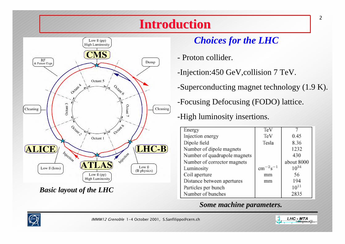
2Introduction Introduction
Basic layout of the LHC
Some machine parameters.
Choices for the LHC
- Proton collider.
-Injection:450 GeV,collision 7 TeV.
-Superconducting magnet technology (1.9 K).
-Focusing Defocusing (FODO) lattice.
-High luminosity insertions.
IMMW12 Grenoble 1-4 October 2001, [email protected]
3
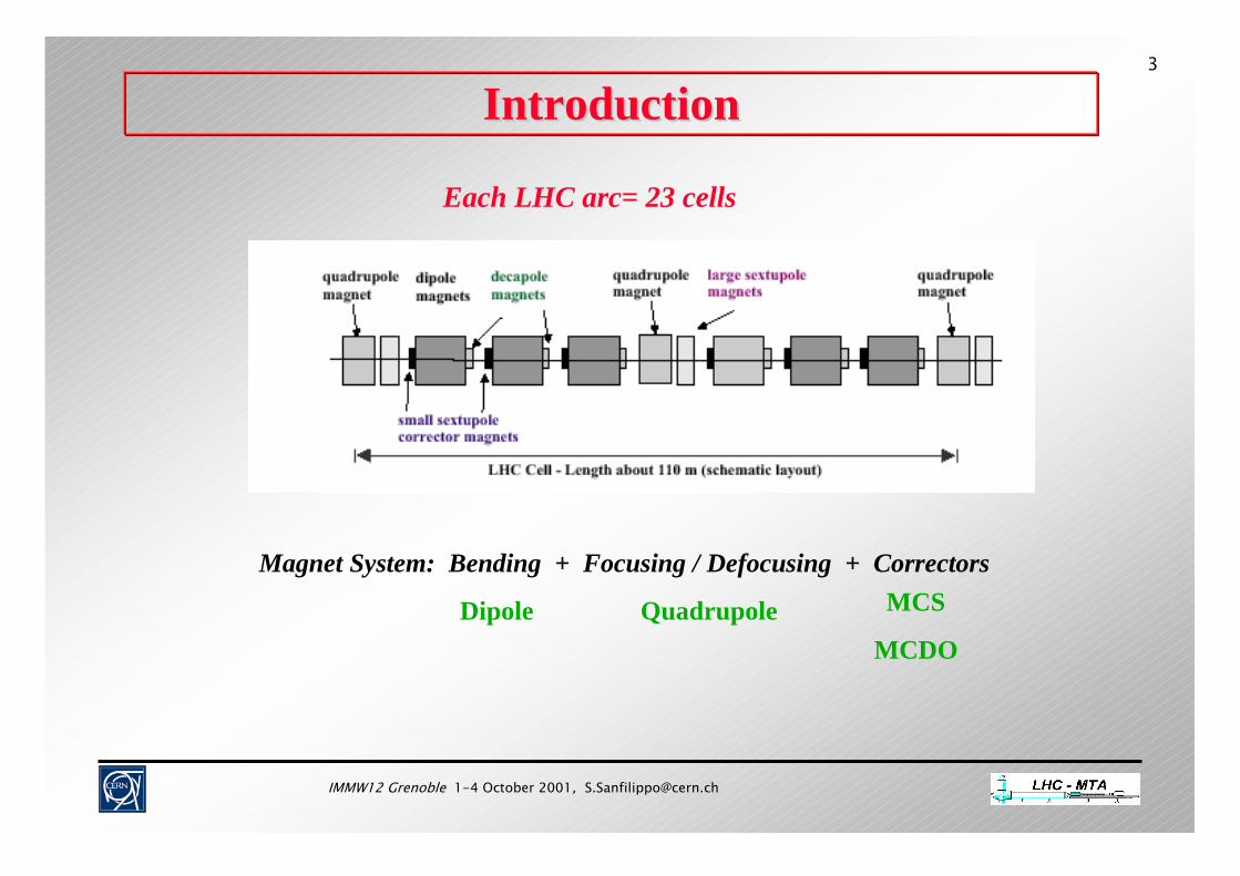
Introduction Introduction
Each LHC arc= 23 cells
Magnet System: Bending + Focusing / Defocusing + Correctors
QuadrupoleDipole MCS
MCDO
IMMW12 Grenoble 1-4 October 2001, [email protected]
4
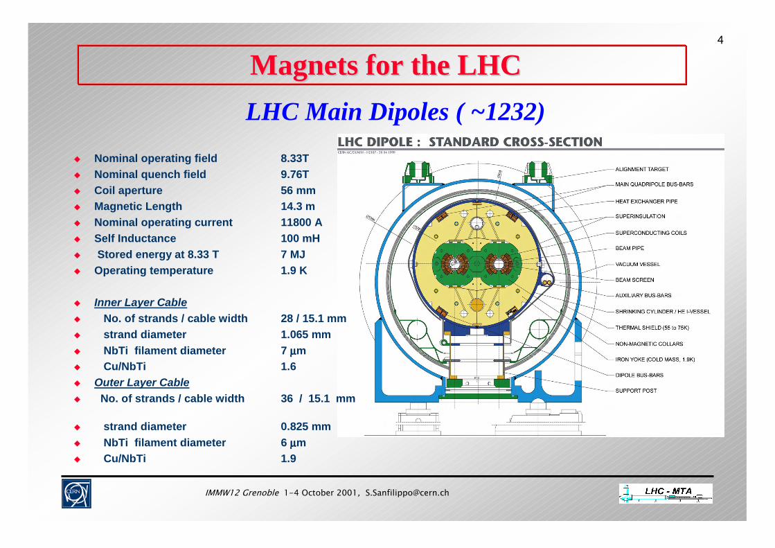
Magnets for the LHC Magnets for the LHC LHC Main Dipoles ( ~1232)
Nominal operating field 8.33T Nominal quench field 9.76T Coil aperture 56 mm Magnetic Length 14.3 m Nominal operating current 11800 A Self Inductance 100 mH Stored energy at 8.33 T 7 MJ Operating temperature 1.9 K
Inner Layer Cable No. of strands / cable width 28 / 15.1 mm strand diameter 1.065 mm NbTi filament diameter 7 µµµµm Cu/NbTi 1.6 Outer Layer Cable No. of strands / cable width 36 / 15.1 mm
strand diameter 0.825 mm NbTi filament diameter 6 µµµµm Cu/NbTi 1.9
IMMW12 Grenoble 1-4 October 2001, [email protected]
5
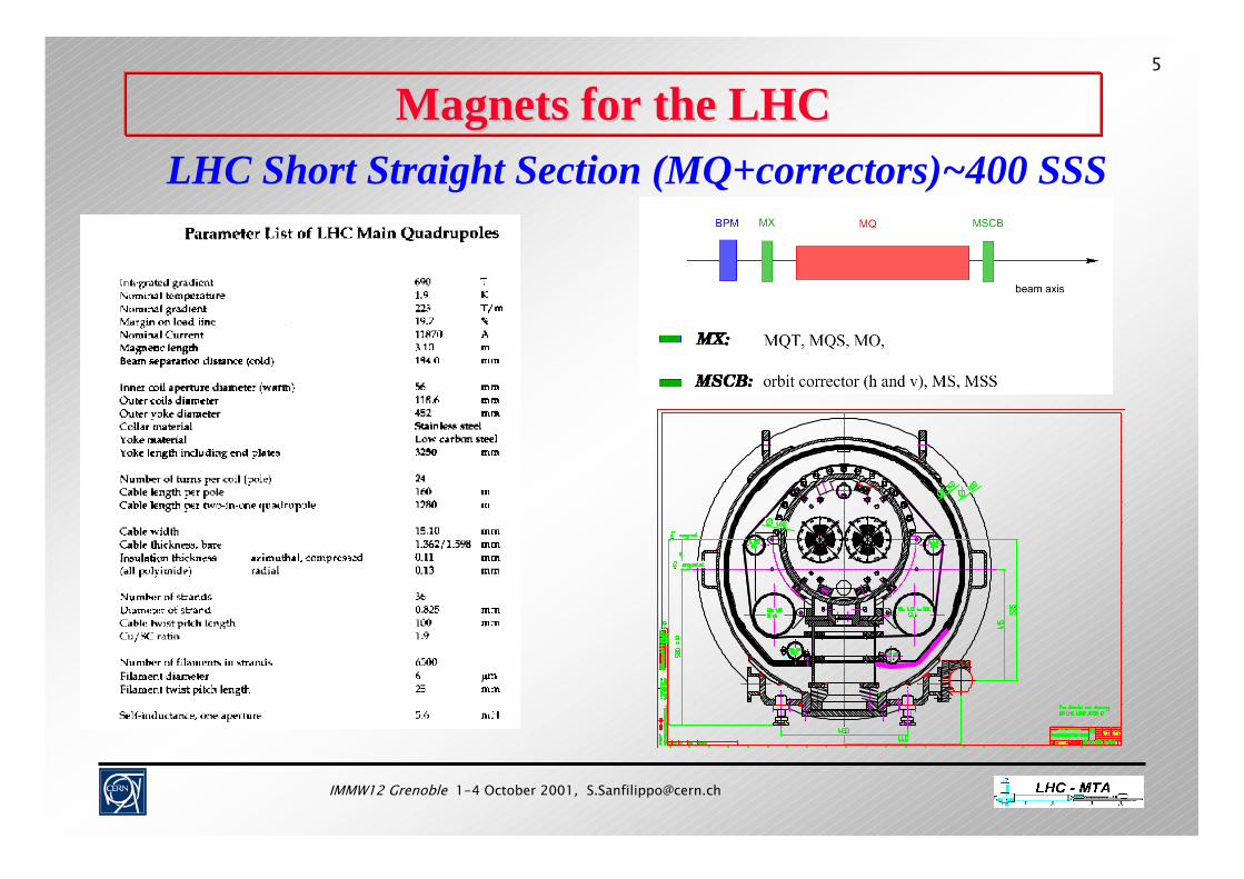
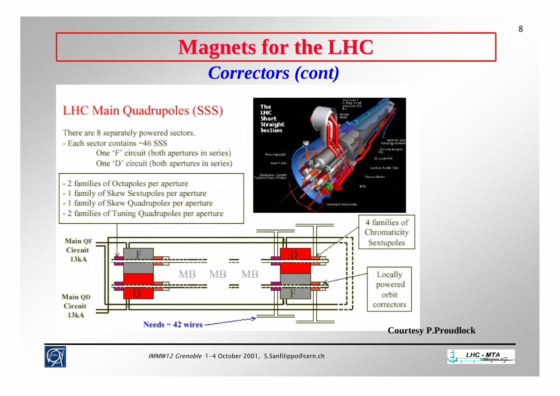
Magnets for the LHC Magnets for the LHC LHC Short Straight Section (MQ+correctors)~400 SSS
IMMW12 Grenoble 1-4 October 2001, [email protected]
6
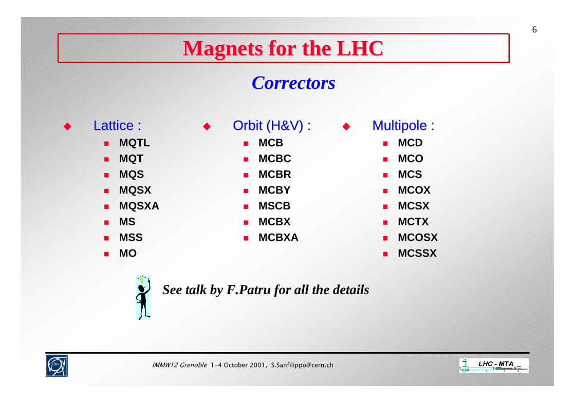
Magnets for the LHC Magnets for the LHC Correctors
Lattice :Lattice : MQTL MQT MQS MQSX MQSXA MS MSS MO
MultipoleMultipole :: MCD MCO MCS MCOX MCSX MCTX MCOSX MCSSX
Orbit (H&V) :Orbit (H&V) : MCB MCBC MCBR MCBY MSCB MCBX MCBXA
See talk by F.Patru for all the details

IMMW12 Grenoble 1-4 October 2001, [email protected]
7
Magnets for the LHC Magnets for the LHC Correctors (cont)
LHC Main Dipole Correctors:
b3 CorrectorsNested b4/b5 Correctors Two-in-one Dipole
Main Dipole Circuit, 13kAb3 corrector circuit, ±600Ab5 corrector circuit, ±600Ab4 corrector circuit, ±120A
b3 corrector circuit, ±600Ab5 corrector circuit, ±600Ab4 corrector circuit, ±120A
Exte
rnal
Ape
rture
Inte
rnal
Ape
rture
b3 Correctors
Main Dipole Circuit, 13kA
b3 corrector circuit, ±600ASpare circuitSpare circuit
b4 corrector circuit, ±120A
Exte
rnal
Ape
rture
Inte
rnal
Ape
rture
Spare circuitSpare circuit
Two-in-one Dipole
TYPE
ATY
PE B
IMMW12 Grenoble 1-4 October 2001, [email protected]
8
Magnets for the LHC Magnets for the LHC Correctors (cont)
Courtesy P.Proudlock
IMMW12 Grenoble 1-4 October 2001, [email protected]
9
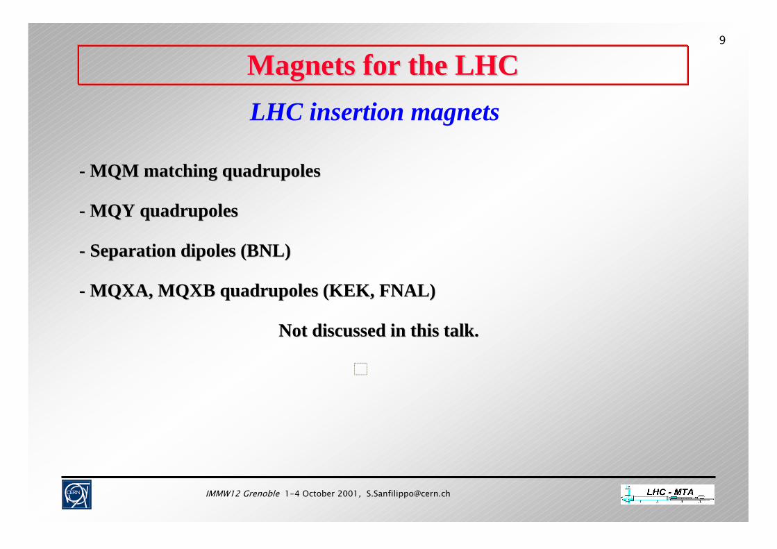
Magnets for the LHC Magnets for the LHC LHC insertion magnets
-- MQM matching MQM matching quadrupolesquadrupoles
-- MQY MQY quadrupolesquadrupoles
-- Separation dipoles (BNL)Separation dipoles (BNL)
-- MQXA, MQXB MQXA, MQXB quadrupoles quadrupoles (KEK, FNAL)(KEK, FNAL)
Not discussed in this talk.Not discussed in this talk.
IMMW12 Grenoble 1-4 October 2001, [email protected]
10
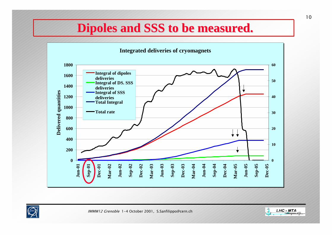
Dipoles and SSS to be measured. Dipoles and SSS to be measured. Integrated deliveries of cryomagnets
0
200
400
600
800
1000
1200
1400
1600
1800
Jun-
01
Sep-
01
Dec
-01
Mar
-02
Jun-
02
Sep-
02
Dec
-02
Mar
-03
Jun-
03
Sep-
03
Dec
-03
Mar
-04
Jun-
04
Sep-
04
Dec
-04
Mar
-05
Jun-
05
Sep-
05
Dec
-05
Del
iver
ed q
uant
ities
0
10
20
30
40
50
60
Integral of dipolesdeliveriesIntegral of DS. SSSdeliveriesIntegral of SSSdeliveriesTotal Integral
Total rate

IMMW12 Grenoble 1-4 October 2001, [email protected]
11
SuperconductingSuperconducting Magnet Tests Plant (SMTP ) in SM18Magnet Tests Plant (SMTP ) in SM18-- 12 test benches for cold tests at CERN.12 test benches for cold tests at CERN.
1 test bench
( for dipole or SSS)
- Dipoles and/or SSS units attached to one of 12 test stations.- Test capacity : up to 60
magnet tests per month.- Tests will focus on :- quench performance- magnet protection- magnetic measurements- acceptance of cryogenic, insulation vacuum, and electric integrity

IMMW12 Grenoble 1-4 October 2001, [email protected]
12
Components critical for field qualityComponents critical for field quality♦♦ Coil characteristicsCoil characteristics♦♦ CollarsCollars
--geometrygeometry--magnetic propertiesmagnetic properties
♦♦ Iron yoke and insertsIron yoke and inserts-- geometrygeometry-- magnetic propertiesmagnetic properties--”two in one” configuration”two in one” configuration
♦♦ Properties of the Properties of the NbTi NbTi RutherfordRutherford cables.cables.-- magnetisation at 0.5 Tmagnetisation at 0.5 T
controlled within 4.5 %.controlled within 4.5 %.-- minimum inter strand minimum inter strand
resistance of 20 resistance of 20 µΩµΩµΩµΩµΩµΩµΩµΩ..

IMMW12 Grenoble 1-4 October 2001, [email protected]
13
Origins of the field errors Origins of the field errors
winding geometry (warm and cold, lo-B & hi-B),
saturation (cold, hi-B),
errors related to the diamagnetic behaviour of superconductingstrands and cables:- effect of the persistent currents,- ramp rate induced harmonic errors (eddy currents),- decay of the persistent currents at injection plateau
and snap-back phenomena during the following ramp.
IMMW12 Grenoble 1-4 October 2001, [email protected]
14
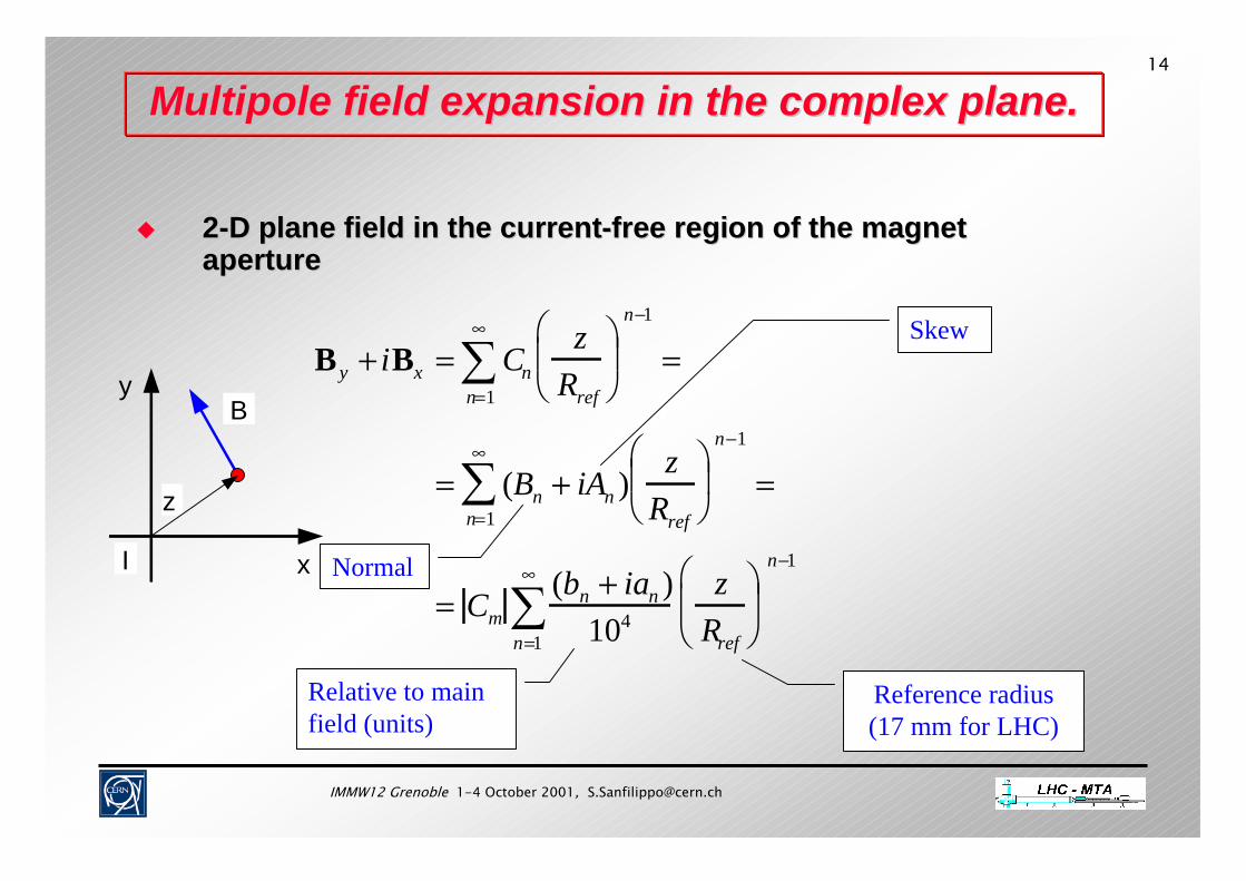
MultipoleMultipole field expansion in the complex plane.field expansion in the complex plane.
22--D plane field in the currentD plane field in the current--free region of the magnet free region of the magnet apertureaperture
x
y
z
B
I
B y + iBx = Cnz
Rref
n=1
∞
∑
n−1
=
= (Bn + iAn )z
Rref
n=1
∞
∑
n−1
=
= Cm(bn + ian )
104
zRref
n=1
∞
∑
n−1
Skew
Normal
Reference radius(17 mm for LHC)
Relative to main field (units)

IMMW12 Grenoble 1-4 October 2001, [email protected]
15
Beam requirements Beam requirements LHC machine: Luminosity of 10 34 cm-2 s-1.
Effect of the field errors:- unstable transverse particle motion (amplitude growth, larger beam size)- aperture restrictions beam losses Reduced luminosity
Quenches
Beam requirements for the field quality:- maximize the Mechanical Aperture,- maximize the Dynamical Aperture,- beam parameters variations.
IMMW12 Grenoble 1-4 October 2001, [email protected]
16
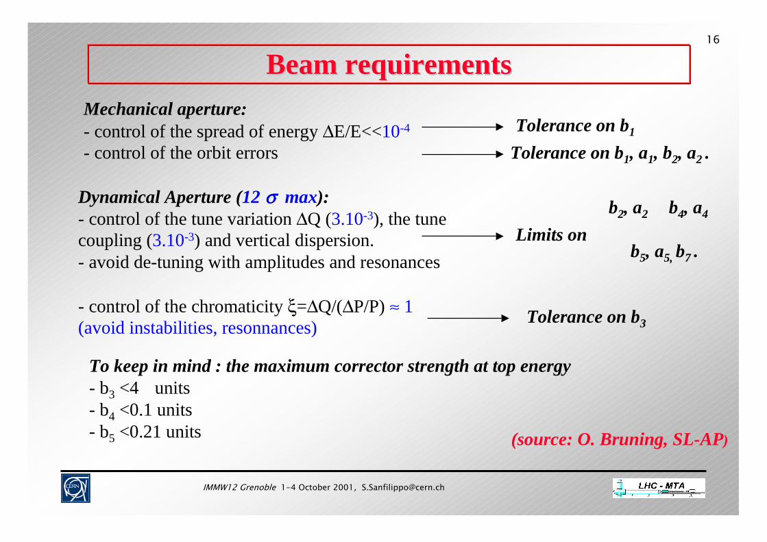
Beam requirementsBeam requirementsMechanical aperture:- control of the spread of energy ∆E/E<<10-4
- control of the orbit errorsTolerance on b1
Tolerance on b1, a1, b2, a2 .
Dynamical Aperture (12 σσσσ
max):- control of the tune variation ∆Q (3.10-3), the tune coupling (3.10-3) and vertical dispersion.- avoid de-tuning with amplitudes and resonances
- control of the chromaticity ξ=∆Q/(∆P/P) ≈ 1(avoid instabilities, resonnances)
b2, a2
Limits onb4, a4
b5, a5, b7 .
Tolerance on b3
To keep in mind : the maximum corrector strength at top energy- b3 <4 units - b4 <0.1 units- b5 <0.21 units (source: O. Bruning, SL-AP)

IMMW12 Grenoble 1-4 October 2001, [email protected]
17
multipole systematic uncertainty randomb1 0.3 0.8 0.13b2 0.55a2 0.8b3 0.02a3 0.17 2.1b4 0.07 0.49b5 0.18
Consequences on field quality (units) Consequences on field quality (units)
For a series production :Systematic = average value (gaussian distribution)Random = standard deviation σ (gaussian distribution)Uncertainty (in the average) = bias from the expected systematic value.

IMMW12 Grenoble 1-4 October 2001, [email protected]
18
Beam requirementsBeam requirements
(source: W.Scandale, LHC/MMS)
Tight tolerances on alignment.

IMMW12 Grenoble 1-4 October 2001, [email protected]
19
Target field quality for series production (Dipoles)Target field quality for series production (Dipoles)
From S.Fartoukh and O.Bruning, LHC Report in press
Multipoles Systematic(max value)
(units)
Uncertainty(max value)
(units)
Random(r.m.s)(units)
b1 None 6.5 8.0
a1 6.5 average per arc cell 8.0
b2 1.4 0.8 0.7 (injection)0.8 (collision 7 TeV )
a2 0.9 1.9 (injection)2.3 ( end of ramp)
1.6 (collision 7 TeV)b3 -10.7
(injection)3.0 (collision)
Including biasdue to
uncertainty
1.4 (injection)1.8 (collision 7 TeV )
a3 1.5 0.7
b4 0.4 0.49a4 0.2 0.5
b5 1.1 (injection)0.8 (collision)
Including biasdue to
uncertainty
0.5 (injection)0.4 (collision 7 Tev )
a5 0.4 0.4

IMMW12 Grenoble 1-4 October 2001, [email protected]
20
Target field quality for series production (MQ)Target field quality for series production (MQ)
Upper(lower) limit: nominal+(-) allowed systematic errors+(-)2* allowed random errors.
I=12000 A

IMMW12 Grenoble 1-4 October 2001, [email protected]
21
How to fill the gap? How to fill the gap?
Field quality requirements from beam physics will not be satisfiField quality requirements from beam physics will not be satisfied by the ed by the magnets as produced.magnets as produced.
The correction system will fill the gap.The correction system will fill the gap.
Effective if the field errors are known at operating conditions
or beam induced effects can be measured and controlled !
IMMW12 Grenoble 1-4 October 2001, [email protected]
22
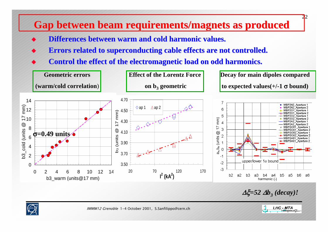
Gap between beam requirements/magnets as producedGap between beam requirements/magnets as produced Differences between warm and cold harmonic values.Differences between warm and cold harmonic values. Errors related to Errors related to superconducting superconducting cable effects are not controlled.cable effects are not controlled. Control the effect of the electromagnetic load on odd harmonics.Control the effect of the electromagnetic load on odd harmonics.
Geometric errors
(warm/cold correlation)
0
2
4
6
8
10
12
14
0 2 4 6 8 10 12 14b3_warm (units@17 mm)
b3_c
old
(uni
ts @
17
mm
)
σσσσ=0.49 units
3.50
3.70
3.90
4.10
4.30
4.50
4.70
20 70 120 170I2 (kA2)
b3 (
units
@ 1
7 m
m) ap 1 ap 2
Effect of the Lorentz Force
on b3 geometric
Decay for main dipoles compared
to expected values(+/-1 σσσσ bound)
∆ξ∆ξ∆ξ∆ξ=52 ∆∆∆∆b3 (decay)!
IMMW12 Grenoble 1-4 October 2001, [email protected]
23
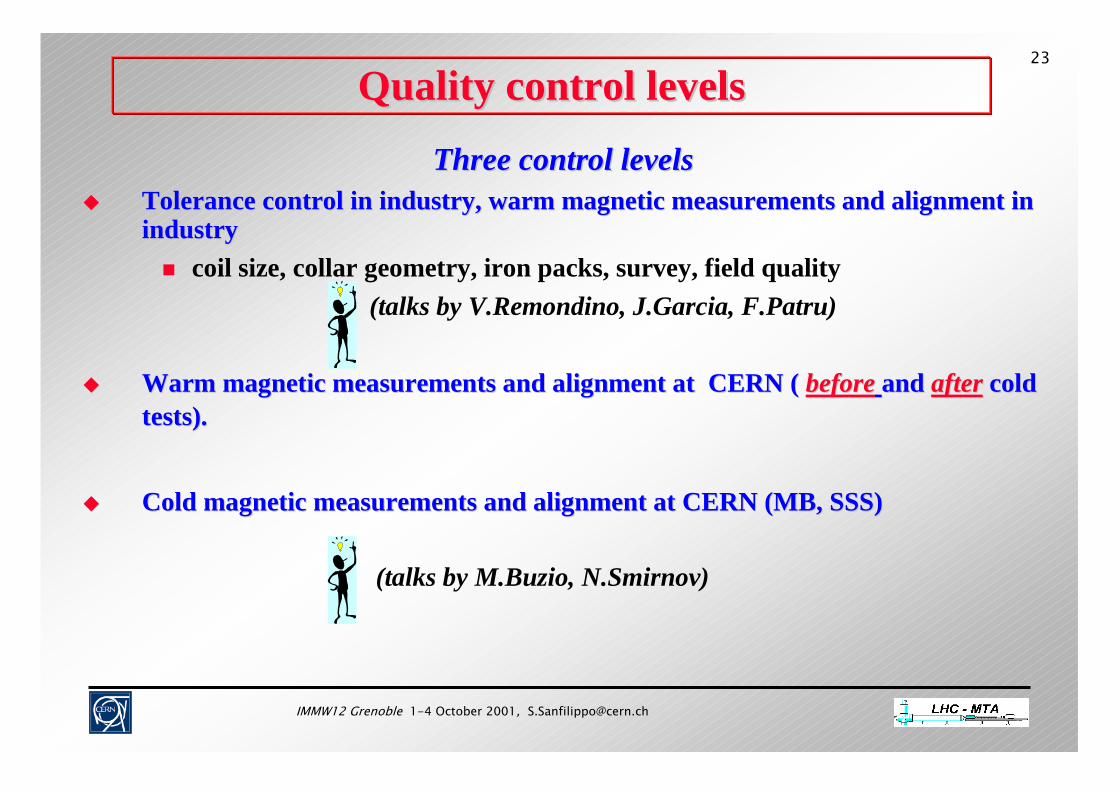
Quality control levelsQuality control levels
Three control levelsThree control levels Tolerance control in industry, warm magnetic measurements and alTolerance control in industry, warm magnetic measurements and alignment in ignment in
industry industry coil size, collar geometry, iron packs, survey, field quality
(talks by V.Remondino, J.Garcia, F.Patru)
Warm magnetic measurements and alignment at CERN (Warm magnetic measurements and alignment at CERN ( beforebefore and and afterafter cold cold tests).tests).
Cold magnetic measurements and alignment at CERN (MB, SSS)Cold magnetic measurements and alignment at CERN (MB, SSS)
(talks by M.Buzio, N.Smirnov)
IMMW12 Grenoble 1-4 October 2001, [email protected]
24
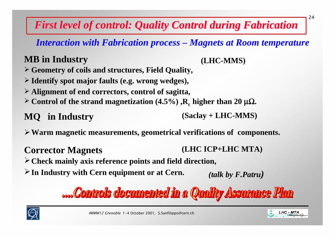
First level of control:First level of control: Quality Control during FabricationQuality Control during FabricationInteraction with Fabrication process – Magnets at Room temperature
(talk by F.Patru)
MQ in Industry (Saclay + LHC-MMS)
Corrector MagnetsCheck mainly axis reference points and field direction,In Industry with Cern equipment or at Cern.
(LHC ICP+LHC MTA)
Warm magnetic measurements, geometrical verifications of components.
MB in Industry (LHC-MMS) Geometry of coils and structures, Field Quality, Identify spot major faults (e.g. wrong wedges),
Control of the strand magnetization (4.5%) ,Rc higher than 20 µΩµΩµΩµΩ. Alignment of end correctors, control of sagitta,

IMMW12 Grenoble 1-4 October 2001, [email protected]
25TESTS AT CERNTESTS AT CERN
Warm re-testing of the cold masses before cool-down as a cross-check of factory tests and control of the transportation effect:
- quality of the magnetic field at warm,
- magnetic axis measurements (dipoles+correctors) .
Tests of the cold masses in warm or cold conditions
At this stage the control of the cold properties is not possible:
- deformation during cool down and under e.m. loads,
- iron saturation and superconducting cable effects.
IMMW12 Grenoble 1-4 October 2001, [email protected]
26
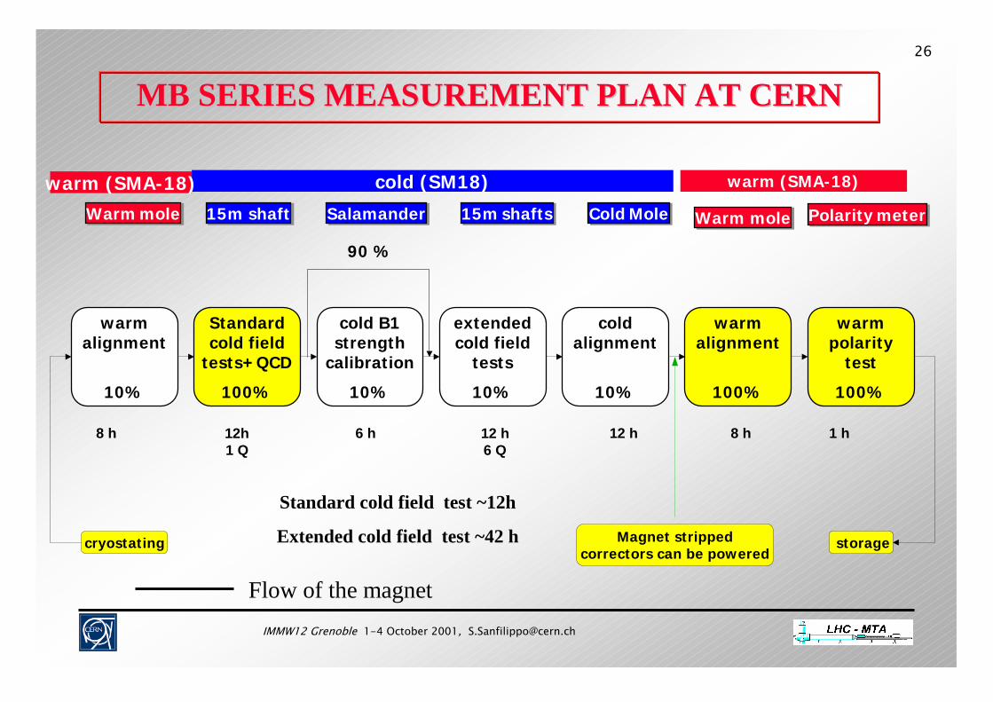
MB SERIES MEASUREMENT PLAN AT CERNMB SERIES MEASUREMENT PLAN AT CERN
90 %
8 h 12h1 Q
6 h 12 h12 h6 Q
8 h 1 h
Magnet strippedcorrectors can be powered
storagecryostating
warm alignment
10%
Standard cold field
tests+QCD
100%
cold B1 strength
calibration
10%
extended cold field
tests
10%
cold alignment
10%
warm alignment
100%
warm polarity
test
100%
cold (SM18) warm (SMA-18)warm (SMA-18)
Warm moleWarm mole Warm moleWarm moleCold MoleCold Mole15m shaft15m shaft 15m shafts15m shaftsSalamanderSalamander Polarity meterPolarity meter
Standard cold field test ~12h
Extended cold field test ~42 h
Flow of the magnet

IMMW12 Grenoble 1-4 October 2001, [email protected]
27
SSS SERIES MEASUREMENT PLAN AT CERNSSS SERIES MEASUREMENT PLAN AT CERN
cold (SM18) warm (SM18)
10h1Q
12h6 Q
40 %
16h2Q
6 h 12h6 Q
8 h
1 h
Standard cold field tests
50%
Cold alignment
50%
Cold gradient & direction calibration
10%
Cold alignment50%
Cold extended field test
10%
Warm alignement
50%
MoleMole
5 m shafts5 m shafts
ScannerScanner Polarity meterPolarity meter
Warm polarity test
50%
Standard cold field tests
50%
6 h
Streched wireStreched wire 40 %
Warm alignement
50%
MoleMole
6 h
Warm polarity test
50%
Polarity meterPolarity meter
1 h
Scanner
Flow of the magnet
IMMW12 Grenoble 1-4 October 2001, [email protected]
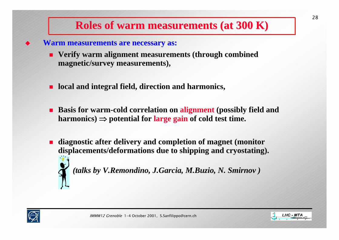
28
Roles of warm measurements (at 300 K)Roles of warm measurements (at 300 K) Warm measurements are necessary as:Warm measurements are necessary as:
Verify warm alignment measurements (through combined magnetic/survey measurements),
local and integral field, direction and harmonics,
Basis for warm-cold correlation on alignment (possibly field and harmonics) ⇒⇒⇒⇒ potential for large gain of cold test time.
diagnostic after delivery and completion of magnet (monitor displacements/deformations due to shipping and cryostating).
(talks by V.Remondino, J.Garcia, M.Buzio, N. Smirnov )

IMMW12 Grenoble 1-4 October 2001, [email protected]
29
Role of standard cold measurements Role of standard cold measurements
Magnetic measurements (and alignment for SSS only): Magnetic measurements (and alignment for SSS only): Parameters for quantitative field quality model in standard conditions
(linear and non-linear effects):geometric eddy decaysaturation persistent
Effect of the cool down on the deformation of the cold mass and cryostat geometry,
thermal contraction and deformation of the feet.
100 % testing necessary to: 100 % testing necessary to: provisional acceptance of the magnets, provide databases for LHC installation, commissioning and operation.

IMMW12 Grenoble 1-4 October 2001, [email protected]
30
Extended cold measurements Extended cold measurements
Magnetic measurement (and alignment for MB only) performed :Magnetic measurement (and alignment for MB only) performed : measurements at injection with different powering history, harmonic measurements after quenches and current cycles, measure of the field direction (cold mole)
Extended cold tests are necessary to:Extended cold tests are necessary to: determine the scaling laws for non-linear behaviors(ex: decay and snap-back as a function of powering history), check the harmonic stability after quenches and after an accelerated life test
(simulation of the life of the machine), verify alignment of MB and correctors in cold conditions, advance R&D for understanding of magnets.
(talk by M.Buzio )
IMMW12 Grenoble 1-4 October 2001, [email protected]
31
Warm alignment after cool down Warm alignment after cool down
Measurement performed for 100% of the dipoles (and associated Measurement performed for 100% of the dipoles (and associated correctors) and the SSS.correctors) and the SSS.
Measurement performed at the latest possible time before the insMeasurement performed at the latest possible time before the installation in tallation in the tunnel.the tunnel.
Identify any movements in the cold masses during cold test (magnetic measurements with rotating coil+QCD , optical measurement of coil rotation center, laser tracker for fiducialisation)
IMMW12 Grenoble 1-4 October 2001, [email protected]
32Corrector MagnetsCorrector Magnets
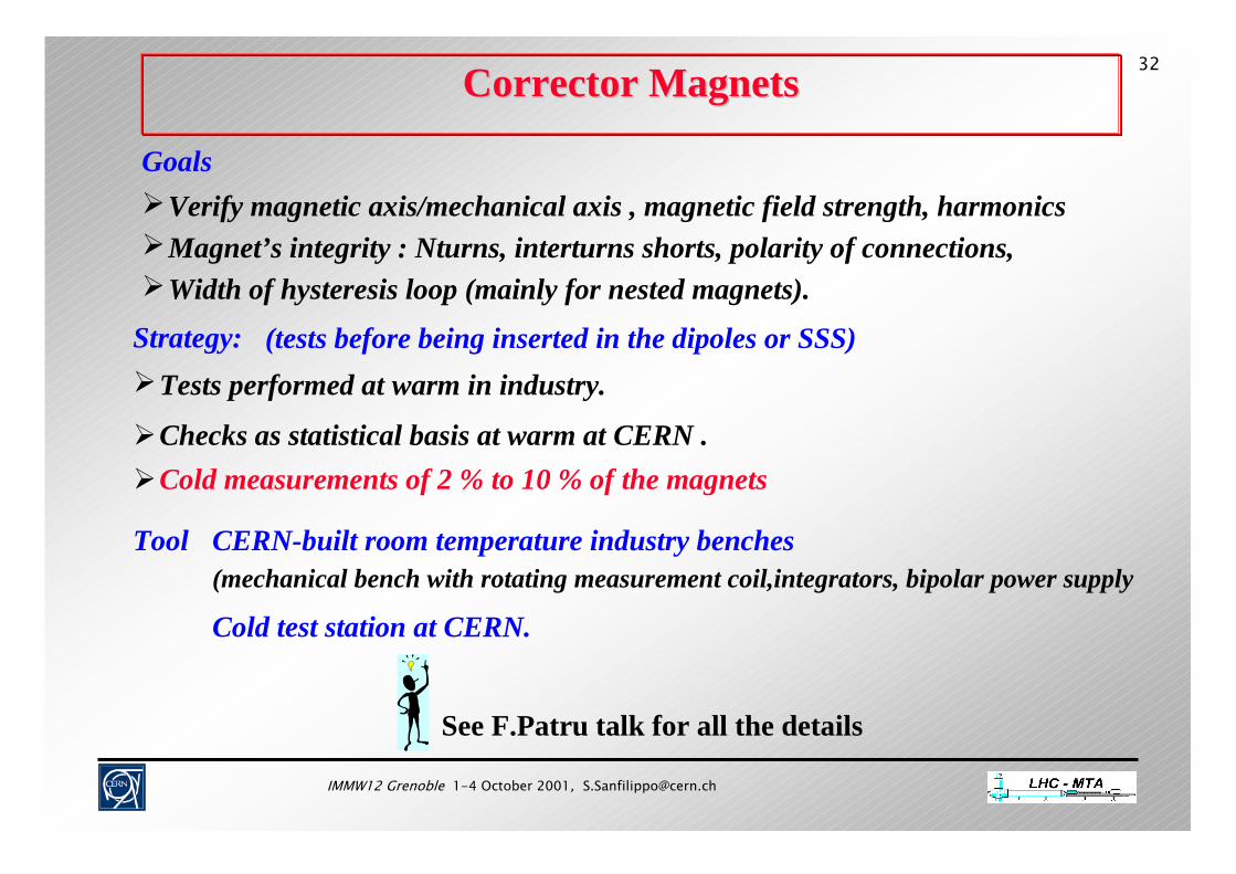
GoalsVerify magnetic axis/mechanical axis , magnetic field strength, harmonicsMagnet’s integrity : Nturns, interturns shorts, polarity of connections,Width of hysteresis loop (mainly for nested magnets).
Strategy: (tests before being inserted in the dipoles or SSS)
Cold measurements of 2 % to 10 % of the magnetsChecks as statistical basis at warm at CERN .
Tool CERN-built room temperature industry benches(mechanical bench with rotating measurement coil,integrators, bipolar power supply
Cold test station at CERN.
See F.Patru talk for all the details
Tests performed at warm in industry.

IMMW12 Grenoble 1-4 October 2001, [email protected]
33
See F.Patru talk for all the details
Criteria of acceptance for the correctors Criteria of acceptance for the correctors
Misalignment Magnetic/mechanical axis: 0.1 m rad max
Roll angles: from 1.5 to 2.5 m rad depending on the correctors
Main field strength: maximum spread of 1% around the average
All harmonics: below 1% of the main field at 17 mm radius
IMMW12 Grenoble 1-4 October 2001, [email protected]
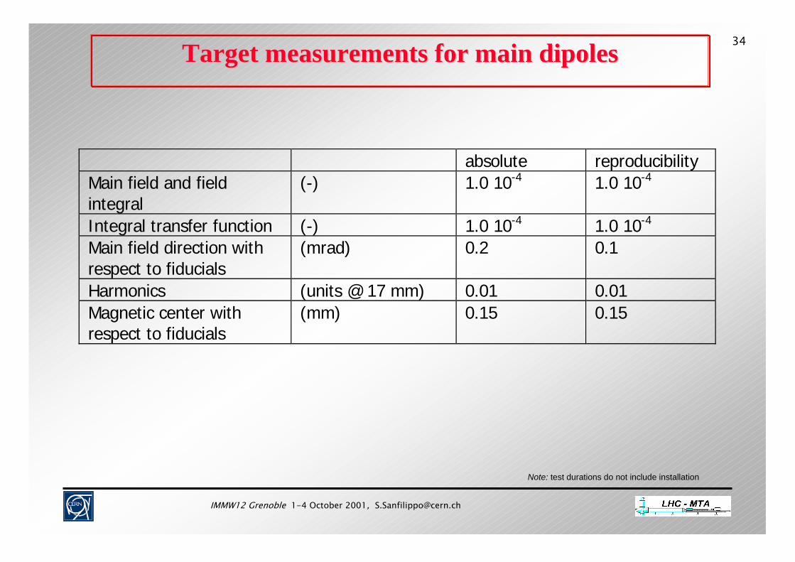
34Target measurements for main dipolesTarget measurements for main dipoles
Note: test durations do not include installation
absolute reproducibilityMain field and fieldintegral
(-) 1.0 10-4 1.0 10-4
Integral transfer function (-) 1.0 10-4 1.0 10-4
Main field direction withrespect to fiducials
(mrad) 0.2 0.1
Harmonics (units @ 17 mm) 0.01 0.01Magnetic center withrespect to fiducials
(mm) 0.15 0.15
IMMW12 Grenoble 1-4 October 2001, [email protected]
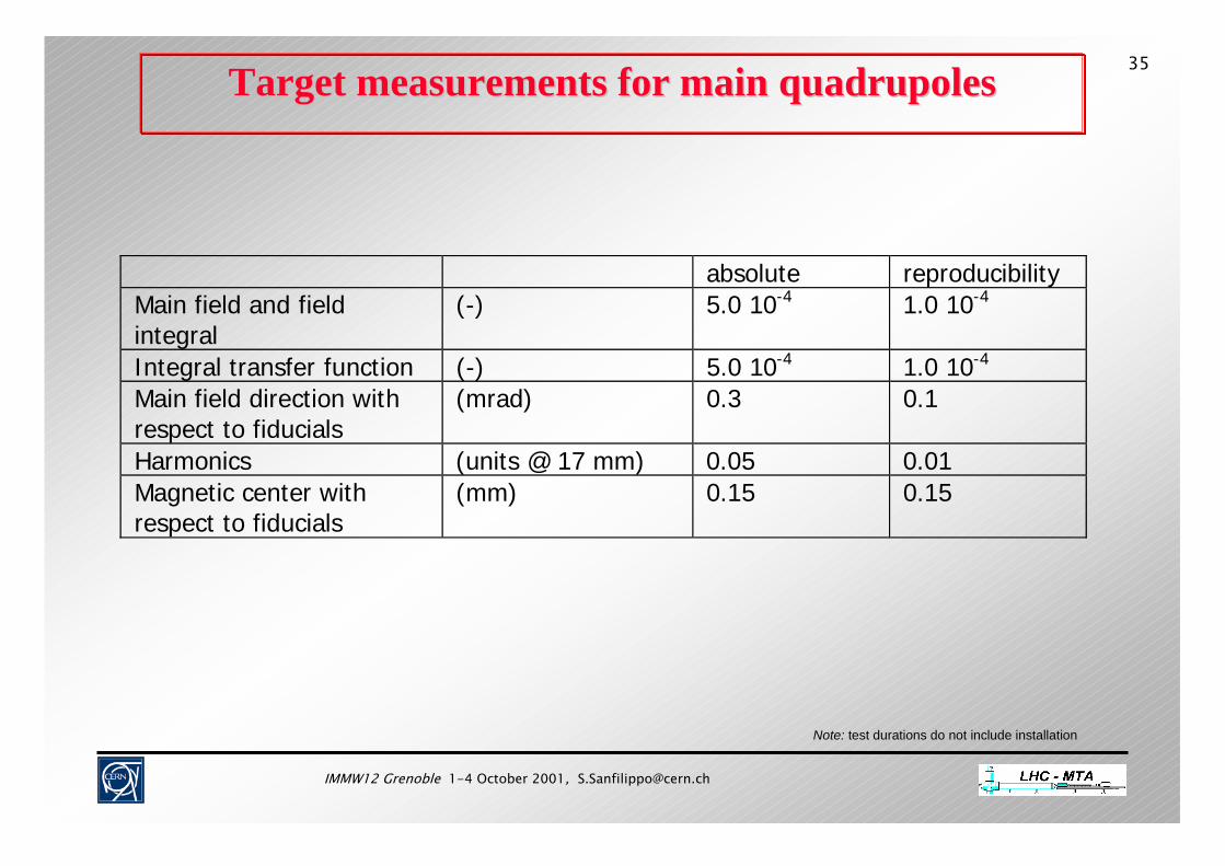
35Target measurements for main Target measurements for main quadrupolesquadrupoles
Note: test durations do not include installation
absolute reproducibilityMain field and fieldintegral
(-) 5.0 10-4 1.0 10-4
Integral transfer function (-) 5.0 10-4 1.0 10-4
Main field direction withrespect to fiducials
(mrad) 0.3 0.1
Harmonics (units @ 17 mm) 0.05 0.01Magnetic center withrespect to fiducials
(mm) 0.15 0.15
IMMW12 Grenoble 1-4 October 2001, [email protected]
36
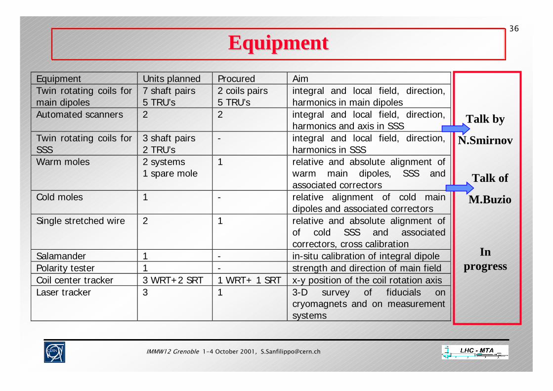
EquipmentEquipmentEquipment Units planned Procured AimTwin rotating coils formain dipoles
7 shaft pairs5 TRU’s
2 coils pairs5 TRU’s
integral and local field, direction,harmonics in main dipoles
Automated scanners 2 2 integral and local field, direction,harmonics and axis in SSS
Twin rotating coils forSSS
3 shaft pairs2 TRU’s
- integral and local field, direction,harmonics in SSS
Warm moles 2 systems1 spare mole
1 relative and absolute alignment ofwarm main dipoles, SSS andassociated correctors
Cold moles 1 - relative alignment of cold maindipoles and associated correctors
Single stretched wire 2 1 relative and absolute alignment ofof cold SSS and associatedcorrectors, cross calibration
Salamander 1 - in-situ calibration of integral dipolePolarity tester 1 - strength and direction of main fieldCoil center tracker 3 WRT+2 SRT 1 WRT+ 1 SRT x-y position of the coil rotation axisLaser tracker 3 1 3-D survey of fiducials on
cryomagnets and on measurementsystems
Talk by
N.Smirnov
Talk of
M.Buzio
In progress

IMMW12 Grenoble 1-4 October 2001, [email protected]
38
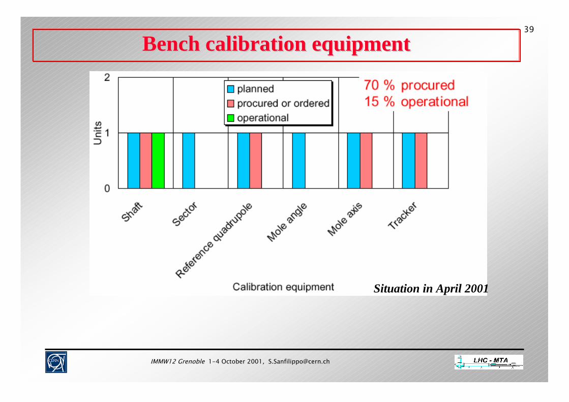
Bench calibration equipmentBench calibration equipment
Talk of
G.Deferne
IMMW12 Grenoble 1-4 October 2001, [email protected]
39
Bench calibration equipmentBench calibration equipment
Situation in April 2001
IMMW12 Grenoble 1-4 October 2001, [email protected]
40
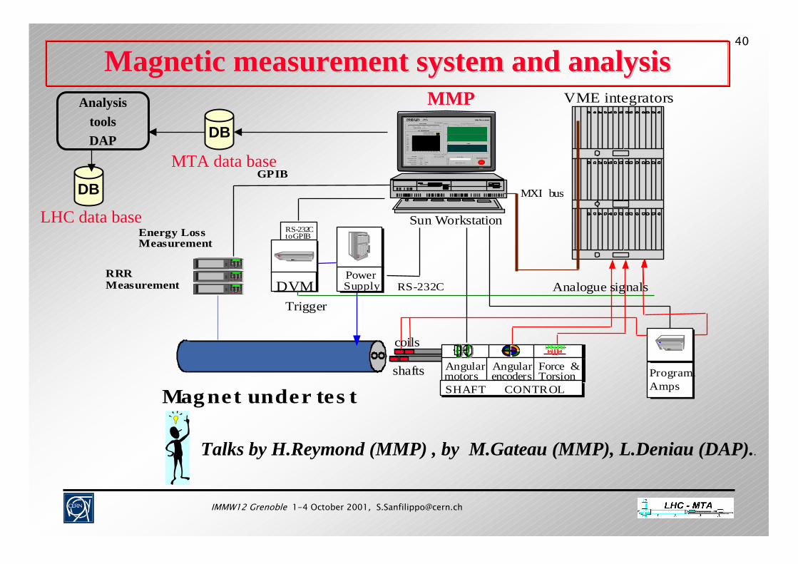
Magnetic measurement system and analysisMagnetic measurement system and analysis
Mag net under tes tAngularmotors
Angularencoders
Force &Torsion
SHAFT CONTROL
PowerSupply
coils
RS-232C
Sun Workstation
DVM
RS-232Cto GPIB
MXI bus
VME integrators
Analogue signalsTrigger
Energy LossMeasurement
GPIB
RRRMeasurement
shafts Program.Amps
Talks by H.Reymond (MMP) , by M.Gateau (MMP), L.Deniau (DAP)..
LHC data base
DB
DB
MTA data base
AnalysistoolsDAP
MMP

IMMW12 Grenoble 1-4 October 2001, [email protected]
41ConclusionsConclusions
I. Magnetic field measurement goal: verification of the field quality in operating conditions fitting with the accuracy required for commissioning and the operation of the LHC.
II. Accuracy not achieved by industrial control and field measurement in warm conditions only. Warm and cold measurement at CERN are necessary.
III. Test plan proposed with all the tests technically feasible within the time allocated.
IV. Adapted test equipment is procured or in process of procurements.