Epson Stylus Photo Service Manual
151
EPSON COLOR INK-JET PRINTER EPSON Stylus Photo SERVICE MANUAL SEIKO EPSON CORPORATION 4007542
-
Upload
shadow30dark -
Category
Documents
-
view
367 -
download
21
Transcript of Epson Stylus Photo Service Manual

EPSON
COLOR INK-JET PRINTER
EPSON Stylus Photo
SERVICE MANUAL
SEIKO EPSON CORPORATION
4007542

ii
NOTICE
� All rights reserved. Reproduction of any part of this manual in any form whatsoever
without SEIKO EPSON’s express written permission is forbidden.
� The contents of this manual are subjects to change without notice.
� All efforts have been made to ensure the accuracy of the contents of this manual.
However, should any errors be detected, SEIKO EPSON would greatly appreciate
being informed of them.
� The above notwithstanding SEIKO EPSON can assume no responsibility for any errors
in this manual or the consequences thereof.
EPSON is a registered trademark of SEIKO EPSON CORPORATION.
General Notice:
Other product names used herein are for identification purposes only and may be
trademarks or registered trademarks of their respective companies.
Copyright 1997 by SEIKO EPSON CORPORATION
Nagano, Japan
iii
PRECAUTIONSPrecautionary notations throughout the text are categorized relative to 1) personal injury and 2)
damage to equipment.
WARNING Signals a precaution which, if ignored, could result in serious or fatal personal injury.
Great caution should be exercised in performing procedures preceded by
WARNING Headings.
CAUTION Signals a precaution which, if ignored, could result in damage to equipment.
The precautionary measures itemized below should always be observed when performing
repair/maintenance procedures.
WARNING1. ALWAYS DISCONNECT THE PRODUCT FROM BOTH THE POWER SOURCE AND
PERIPHERAL DEVICES PERFORMING ANY MAINTENANCE OR REPAIR PROCEDURES.
2. NO WORK SHOULD BE PERFORMED ON THE UNIT BY PERSONS UNFAMILIAR WITH
BASIC SAFETY MEASURES AS DICTATED FOR ALL ELECTRONICS TECHNICIANS IN
THEIR LINE OF WORK.
3. WHEN PERFORMING TESTING AS DICTATED WITHIN THIS MANUAL. DO NOT
CONNECT THE UNIT TO A POWER SOURCE UNTIL INSTRUCTED TO DO SO. WHEN THE
POWER SUPPLY CABLE MUST BE CONNECTED, USE EXTREME CAUTION IN WORKING
ON POWER SUPPLY AND OTHER ELECTRONIC COMPONENTS.
CAUTION1. REPAIRS ON EPSON PRODUCT SHOULD BE PERFORMED ONLY BY EPSON CERTIFIED
REPAIR TECHNICIAN.
2. MAKE CERTAIN THAT THE SOURCE VOLTAGE IS THE SAME AS THE RATED VOLTAGE,
LISTED ON THE SERIAL NUMBER/RATING PLATE. IF THE EPSON PRODUCT HAS A
PRIMARY AC RATING DIFFERENT FROM AVAILABLE POWER SOURCE, DO NOT
CONNECT IT TO THE POWER SOURCE.
3. ALWAYS VERIFY THAT THE EPSON PRODUCT HAS BEEN DISCONNECTED FROM THE
POWER SOURCE BEFORE REMOVING OR REPLACING PRINTED CIRCUIT BOARDS
AND/OR INDIVIDUAL CHIPS.
4. IN ORDER TO PROTECT SENSITIVE MICROPROCESSORS AND CIRCUITRY, USE
STATIC DISCHARGE EQUIPMENT, SUCH AS ANTI-STATIC WRIST STRAPS, WHEN
ACCESSING INTERNAL COMPONENTS.
5. REPLACE MALFUNCTIONING COMPONENTS ONLY WITH THOSE COMPONENTS BY
THE MANUFACTURE; INTRODUCTION OF SECOND-SOURCE ICs OR OTHER
NONAPPROVED COMPONENTS MAY DAMAGE THE PRODUCT AND VOID ANY
APPLICABLE EPSON WARRANTY.

iv
PREFACE
This manual describes functions, theory of electrical and mechanical operations, maintenance, and
repair of EPSON Stylus Photo.
The instructions and procedures included herein are intended for the experience repair technician,
and attention should be given to die precautions on the preceding page. The Chapters are
organized as follows:
CHAPTER 1. GENERAL DESCRIPTIONProvides a general product overview, lists specifications, and illustrates the main components of the
printer.
CHAPTER 2. OPERATING PRINCIPLESDescribes the theory of printer operation.
CHAPTER 3. DISASSEMBLY AND ASSEMBLYIncludes a step-by-step guide for product disassembly and assembly.
CHAPTER 4. ADJUSTMENTIncludes a step-by-step guide for adjustment.
CHAPTER 5. TROUBLESHOOTINGProvides EPSON-approved techniques for troubleshooting.
CHAPTER 6. MAINTENANCEDescribes preventive maintenance techniques and lists lubricants and adhesives required to
service the equipment.
APPENDIXDescribes connector pin assignments, circuit diagrams, circuit board component layout and
exploded diagram.
The contents of this manual are subject to change without notice.

v
REVISION SHEET
Revision Issued Data Contents
Rev. A March 26, 1997 First issue

vi
TABLE OF CONTENTS
CHAPTER 1. GENERAL DESCRIPTIONCHAPTER 2. OPERATING PRINCIPLESCHAPTER 3. DISASSEMBLY AND ASSEMBLYCHAPTER 4. ADJUSTMENTCHAPTER 5. TROUBLESHOOTINGCHAPTER 6. MAINTENANCEAPPENDIX

Chapter 1Product Descriptions
1.1 Features.................................................................................................................1- 1
1.2 Specifications .......................................................................................................1-2 1.2.1 Printing Specification................................................................................................... .......... 1-2
1.2.2 Paper Specification ...................................................................................................... .......... 1-4 1.2.2.1 Cut Sheet................................................................................................................... 1-4 1.2.2.2 Transparency, Glossy Paper ..................................................................................... 1-4 1.2.2.3 Envelope.................................................................................................................... 1-4 1.2.2.4 Index Card................................................................................................................. 1-4
1.2.3 Adjust Lever Settings (PG adjust lever) ............................................................................... 1-5
1.2.4 Printing Area ............................................................................................................ ............... 1-6 1.2.4.1 Cut Sheet................................................................................................................... 1-6 1.2.4.2 Envelope.................................................................................................................... 1-7
1.2.5 Environmental Condition.................................................................................................. ..... 1-8
1.2.6 Ink Cartridge Specifications ............................................................................................. ..... 1-9 1.2.6.1 Black Ink Cartridge.................................................................................................... 1-9 1.2.6.2 Color Ink Cartridge .................................................................................................. 1-10
1.2.7 Physical Specification................................................................................................... ....... 1-11
1.2.8 Input Data Buffer ........................................................................................................ .......... 1-11
1.2.9 Electric Specification ................................................................................................... ........ 1-12
1.2.10 Reliability............................................................................................................. ................ 1-12
1.2.11 Safety Approvals........................................................................................................ ......... 1-12
1.2.12 Acoustic Noise.......................................................................................................... .......... 1-12
1.2.13 CE Marking.................................................................................................................... ...... 1-12
1.2.14 Printer Language and Emulation ...................................................................................... 1-13
1.3 Interface...............................................................................................................1-1 4 1.3.1 Parallel Interface (Forward Channel) .................................................................................. 1-1 4
1.3.2 Parallel Interface (Reverse Channel) .................................................................................. 1-1 5
1.3.3 Serial Interface ......................................................................................................... ............. 1-18
1.3.4 Prevention Hosts from Data Transfer Time-out................................................................. 1-19
1.3.5 Interface Selection...................................................................................................... .......... 1-19
1.4 Control Panel ......................................................................................................1-20 1.4.1 Indicators............................................................................................................... ................ 1-20
1.4.2 Panel Functions.......................................................................................................... .......... 1-21
1.4.3 Printer Condition and Panel Status .................................................................................... 1-2 2
1.5 Error Status.........................................................................................................1-23 1.5.1 Ink Out .................................................................................................................. ................. 1-23
1.5.2 Paper Out................................................................................................................ ............... 1-23
1.5.3 Paper Jam................................................................................................................ .............. 1-23
1.5.4 No Ink-Cartridge ......................................................................................................... .......... 1-24
1.5.5 Maintenance Request...................................................................................................... ..... 1-24
1.5.6 Fatal Errors............................................................................................................. ............... 1-24
1.6 Printer Initialization ............................................................................................1-25
1.7 Initialization Settings..........................................................................................1-25

1.8 Main Components ..............................................................................................1-26 1.8.1 C209 Main Control Board .................................................................................................. ...1-26
1.8.2 C206 PSB/PSE(Power Supply) Board .................................................................................1-27
1.8.3 C209PNL Panel Unit....................................................................................................... .......1-27
1.8.4 Printer Mechanism........................................................................................................ ........1-27
1.8.5 Housing.................................................................................................................. ................1-28

EPSON Stylus Photo
Rev.A 1-1
1.1 FeaturesEPSON Stylus Photo is a high quality color ink jet printer designed for printing photo images and colorgraphics. The major printer features are;
� High color print quality� 720(H) x 720(V) dpi printing� 6 color printing CMYK and output of photo quality by light-C/M� Traditional and New Microwave� 32 nozzles x 6 (Black, Cyan, Magenta, Yellow, Light Cyan, Light Magenta)� During 360 dpi printing, 1 dot is fired by 2 shots, and 1 dot is fired by
1 shot during 720 dpi printing.� Built-in auto sheet feeder
� Holds 100 cut-sheets (55g/‡u)� Holds 10 envelopes� Holds 50 transparency films� Holds 65 special papers
� Built-in 2 I/F� Mac serial I/F(up to approx.900 kbps)� Bi-directional parallel I/F(Nibble mode. IEEE-1284 level 1 device)
� High-speed print� 200cps� By driving the print head at frequency; 14.4KHz, printing speed is twice faster than Stylus Color.
� Windows/Macintosh exclusive� Compact size
� Non-operating : 429mm(W) x 234mm(D) x 162mm(H)� Operating : 429mm(W) x 695mm(D) x 309mm(H)� Weight : 5.2Kg(without cartridge)
� Acoustic noise� Approximately 45 dB
� One unit combined with black and color heads
The following table shows consumable and option.
Item Code RemarkBlack Ink Cartridge S020093 Color: BlackColor Ink Cartridge S020110 Color: Cyan/Magenta/Yellow/Light
Light Cyan/Light MagentaEPSON 360 dpi Ink Jet Paper S041025 Size: A4(200 sheets)EPSON 360 dpi Ink Jet Paper S041059 Size: A4(100 sheets)EPSON 360 dpi Ink Jet Paper S041060 Size: Letter(100 sheets)Photo Quality Ink Jet Paper S041026 Size: A4(200 sheets)Photo Quality Ink Jet Paper S041061 Size: A4(100 sheets)Photo Quality Ink Jet Paper S041062 Size: LetterPhoto Quality Ink Jet Paper S041067 Size: LegalPhoto Quality Glossy Paper(New Release) S041126 Size: A4Photo Quality Glossy Paper(New Release) S041124 Size: LetterPhoto Quality Glossy Film S041071 Size: A4Photo Quality Glossy Film S041072 Size: LetterPhoto Quality Glossy Film S041107 Size: A6Ink Jet Transparencies S041063 Size: A4Ink Jet Transparencies S041064 Size: LetterPhoto Quality Ink Jet Card S041054 Size: A6Photo Quality Ink Jet Card S041121 Size: 5.8 inchesPhoto Quality Ink Jet Card S041122 Size: 10.8 inchesPhoto Quality Self Adhesive Sheet S041106 Size: A4
Table 1-1. Consumables and options

Chapter 1 Product Description
Rev.A1-2
1.2 SpecificationsThis section describes each specification for EPSON Stylus Photo; 1) Printing specification, 2) Paperspecification, 3) Adjust lever settings, 4) Printing area, 5) Environmental condition, 6) Ink Cartridgespecification, 7) Physical specification, 8) Electric specification, 9) Reliability.
1.2.1 Printing Specification
� Print method � On demand ink jet (E-CHIPS type. One unit combined with black and color head)
� Nozzle configuration� Black head: 32 nozzles (Space between nozzle: 90DPI)� Color head: 32 nozzles/ each color x 5 colors (Space between nozzle: 90DPI)
Note) During 360 dpi printing mode, one line is completed by 2-pass for black and by 4-pass for CMYcm.
� Print direction� Bi-direction with logic seeking
� Print speed� Raster Graphics Mode. Refer to Table 1-2.
Horizontal Resolution Printable Area Available Dot CR Speed(IPS)180 dpi 8.26 inch 1488 20 IPS360 dpi 8.26 inch 2976 20 IPS720 dpi 8.26 inch 5952 20 IPS
� Character Mode*. Refer to Table 1-3.
Character Pitch Printable Colums LQ Speed10CPI 80 200CPS **
Note) * Reference only. **This value is the speed of one print-pass in which the 1/4of character matrix is printed.
� Nozzle arrangement� Refer to figure1-1.
Table 1-2. Raster Graphics Mode
Table 1-3. Character Mode
#1
#32
22.5777 mm
(320/360")
2.2578 mm(32/360")
10.16 mm(144/360")
0.2
82
2 m
m(4
/36
0")
Black Cyan Light Cyan Magenta Light Magenta Yellow
Figure 1-1. Head Nozzle Arrangement

EPSON Stylus Photo
Rev.A 1-3
� Feeding method� Friction feed with ASF
� Line spacing� 1/6 inch or programmable at 1/360 inch
� Paper path� Cut-sheet ASF(Top entry)
� Feeding speed� 66.6ms (1/6 inch)� 3.0 inch/sec (Continuous)
� Ink supply� Exclusive ink cartridge(Black and CMYcm)
� Built in ASF� Size : Index card•` Legal� Thickness : Less than 8mm� Paper capacity : Holds 100 Cut sheets
: Holds 10 Envelopes: Holds 10 transparency sheet: Holds 65 ink jet papers (A4): Holds 30 index card (A6): Holds 30 glossy papers
Note1) Those numbers above should be considered as reference. The actual paper accumulation should be considered first.
Note2) The printer can hold 10 transparency sheets only when the top margin is 30mm. Otherwise, onlyone sheet can be hold.
Note3) Change the paper support position for the transparency printing position when you print on the transparency sheet.
� Character tables*� PC437(US, Standard Europe)� PC850(Multilingual)
� Typeface*� Bit map LQ font : EPSON Courier 10CPI
� Control code� ESC/P Raster� EPSON Remote command
Note) * Reference only.

Chapter 1 Product Description
Rev.A1-4
1.2.2 Paper SpecificationThis section describes the printable area and types of paper that can be used in this printer.Note) Do not perform reverse feed more than 9.5mm(0.38”).
1.2.2.1 Cut Sheet
[Size] : A4 [Width 210mm(8.3”) x Length 297mm(11.7”)]: Letter [Width 216mm(8.5”) x Length 279mm(11.0”)]: B5 [Width 182mm(7.2”) x Length 257mm(10.1”)]: Legal [Width 216mm(8.5”) x Length 356mm(14.0”)]: Statement [Width 139.7mm(5.5”) x Length 215.9mm(8.5”)]: Exclusive [Width 190.5mm(7.5”) x Length 254mm(10”)]
[Thickness] : 0.08mm(0.003”) - 0.11mm(0.004”)
[Weight] : 64g/m2 (17Ib.) - 90g/m2 (24Ib.)
[Quality] : Exclusive paper, Bond paper, PPC
1.2.2.2 Transparency, Glossy Paper
[Size] : A4 [Width 210mm(8.3”) x Length 297mm(11.7”)]: Letter [Width 216mm(8.5”) x Length 279mm(11.0”)]
[Thickness] : 0.075mm(0.003”) - 0.085mm(0.0033”)
Note) Transparency printing is only available at normal temperature.
1.2.2.3 Envelope
[Size] : No.10 [Width 241mm(9 1/2”) x Length 104.8mm(4 1/8”)]: DL [Width 220mm(8.7”) x Length 110mm(4.3”)]: C6 [Width 162mm(6.4”) x Length 114mm(4.5”)]
[Thickness] : 0.16mm(0.006”) - 0.52mm(0.02”)
[Weight] : 45g/m2 (12Ib.) - 75g/m2 (20Ib.)
[Quality] : Bond paper, Plain paper, Air mail
Note 1) Envelope printing is only available at normal temperature.Note 2) Keep the longer side of the envelope horizontally at setting.
1.2.2.4 Index Card
[Size] : A6 Index card: [Width 105mm(4.1”) x Length 148mm(5.8”)]: A5 Index card: [Width 148mm(5.8”) x Length 210mm(8.3”)]: 5x8” Index card: [Width 127mm(5.0” x Length 203mm(8.0”)]: 10x8” Index card: [Width 127mm(5.0”) x Length 203mm(8.0”)]
[Thickness] : Less than 0.23mm(0.0091”)
Note 1) No curled, wrinkled, scuffing or torn paper be used.Note 2) Set the lever to the proper position according to the paper type you print. (Refer to section
1.2.3 for details)Note 3) Printing should be performed at room temperature in spite of the paper types.Note 4) Perform printing under the room temperature.

EPSON Stylus Photo
Rev.A 1-5
1.2.3 Adjust Lever Settings (PG adjust lever)
The adjust lever located on the right side(blue) that is under the printer cover needs to be set to the properposition according to the paper you print. (Refer to the table below). Also, if there is any dirt caused byfriction on the wavy or wrinkled paper, this can be prevented by changing the lever position to rearposition (marked with “+”) in spite of paper types.
Paper Lever position PG adjustment valueNormal paper,Coated paper
Front (0) 0 mm (1.04mm between head and paper feedassembly)
Envelopes Rear(+) 0.9 mm (1.94mm between head and paperfeed assembly)
Table 1-4. Adjust Lever Settings
+
0Paper Adjust Lever
Figure 1-2. Adjust Lever

Chapter 1 Product Description
Rev.A1-6
1.2.4 Printing Area
1.2.4.1 Cut SheetThe following table shows printable area.
Paper size PW(Paperwidth)(typ)
PL(PaperLength)
(typ.)
LM(Leftmargin)(min.)
RM(Rightmargin)(min.)
TM(Topmargin)(min.)
BM(Bottommargin)(min.)
A4 210mm(8.3”) 297mm(11.7”) 3mm(0.12”) 3mm(0.12”) 3mm(0.12”) 14mm(0.54”)Letter 216mm(8.5”) 279mm(11.0”) 3mm(0.12”) 3mm(0.12”) 3mm(0.12”) 14mm(0.54”)
B5 182mm(7.2”) 257mm(10.1”) 3mm(0.12”) 3mm(0.12”) 3mm(0.12”) 14mm(0.54”)Legal 216mm(8.5”) 356mm(14.0”) 3mm(0.12”) 3mm(0.12”) 3mm(0.12”) 14mm(0.54”)
Statement 139.7mm(5.5”) 215.9mm(8.5”) 3mm(0.12”) 3mm(0.12”) 3mm(0.12”) 14mm(0.54”)Executive 190.5mm(7.5”) 254mm(10”) 3mm(0.12”) 3mm(0.12”) 3mm(0.12”) 14mm(0.54”)
Table 1-5.Printable Area for Cut Sheet
Printable area
LM RM
TM
BM
PL
PW
Figure 1-3. Printing Area for Cut Sheet

EPSON Stylus Photo
Rev.A 1-7
1.2.4.2 EnvelopeThe table and figure below show the printable area for envelopes.
Paper size LM(Left margin)(min.)
RM(Right margin)(min.)
TM(Top margin)(min.)
BM(Bottommargin)(min.)
#10 28mm(1.10”) 3mm(0.12”) 3mm(0.12”) 14mm(0.55”)DL 7mm(0.28”) 3mm(0.12”) 3mm(0.12”) 14mm(0.55”)C6 3mm(0.12”) 3mm(0.12”) 3mm(0.12”) 14mm(0.55”)
Table 1-6. Printable Area for Envelope
Printable Area
LM
TM
RM
BM
Figure 1-4. Printing Area for Envelope

Chapter 1 Product Description
Rev.A1-8
1.2.5 Environmental Condition
� Temperature� Operating :10 to 35°C (Refer to the figure below for condition)� Non-operating : -20 to 60°C (with shipment container)
Note) 1 month at 40°C and 120 hours at 60°C
� Humidity� Operating : 20 - 80% RH (without condensation. Refer to the figure below for
condition)� Non-operating : 5 - 85% RH (without condensation and with shipment container)
� Resistance to shock� Operating : 1G, within 1 ms X,Y,Z directions� Non-operating : 2G, within 2 ms X,Y,Z directions (with shipment container)
� Resistance to vibration� Operating : 0.15G, 10 - 55Hz X,Y,Z directions� Non-operating : 0.50G, 10 - 55Hz X,Y,Z directions (with shipment container)
Note 1) During non-operating, make sure that the head is capped.Note 2) During the transport, make sure that the head is capped and ink cartridge is
installed to the printer.Note 3) If the head is not capped at the power-off state, turn the power on with installed ink
cartridge and turn off the power after confirming that Power on operation is completed andthe head is capped.
Note 4) Ink will be frozen under -4°C environment, however it will be useable after placing itmore than 3 hours at 25°C.
Temperature
Humidity(%RH)
(50 F) (80 F) (95 F) ( F)
Guranteed Range
Figure 1-5. Temperature/Humidity ofRange

EPSON Stylus Photo
Rev.A 1-9
1.2.6 Ink Cartridge Specifications
1.2.6.1 Black Ink Cartridge
Item SpecificationsType Exclusive cartridgeColor BlackPrint capacity 540 pages / A4 (ISO/IE10561 Letter Pattern at 360 dpi)Validity 2 years from production date(sealed in package) / 6months(out of package)Environmentalconditions
� Temperature� Storage : -20 - 40°C (within a month at 40°C)� Packing storage : -30 - 40°C (within a month at 40°C)� Transit : -30 - 60°C (within 120 hours at 60°C and within a month
at 40°C)� Humidity
� 5 - 85%(without condensation)� Resistance to vibration
� Sealed in package : 5 - 55Hz� Acceleration : 29.4m/s less than 3G� Direction : X, Y, Z direction� Time : 1 hour
� Drop� Sealed in package :
� Dropping height : Less than 0.8m� Direction : Drop it facing the 6 areas, bottom, sides and one
edge down.
Dimension 19.8mm(W) x 52.7mm(D) x 38.5mm(H)Weight � Total ink cartridge : 54g
� Total ink :16.4±0.5g (Quantity in the ink cartridge)� Consumable ink :More than 12.1g(Usable ink quantity until ink ends)
Note 1) Ink cartridge can not re-fill, only ink cartridge is prepared for article of consumption.Note 2) Do not use the ink cartridge which is passed away the ink life.Note 3) Ink will be frozen under -4°C environment, however it will be usable after placing it more than
3 hours at room temperature.
Table 1-7. Black Ink Cartridge Specifications
Figure 1-6. Black Ink Cartridge

Chapter 1 Product Description
Rev.A1-10
1.2.6.2 Color Ink Cartridge
Item SpecificationsType Exclusive cartridgeColor 5 Colors(Magenta, Cyan, Yellow, Light Magenta, Light Cyan)Print capacity 190 pages / A4 (360 dpi, 5% duty each color)Validity 2 years from production date (sealed in package) / 6months(out of package)Environmentalconditions
� Temperature� Storage : -20 - 40°C (within a month at 40°C)� Packing storage : -30 - 40°C (within a month at 40°C)� Transit : -30 - 60°C (within 120 hours at 60°C and within a month
at 40°C)� Humidity
� 5 - 85%(without condensation)� Resistance to vibration
� Sealed in package : 5 - 55Hz� Acceleration : 29.4m/s less than 3G� Direction : X, Y, Z direction� Time : 1 hour
� Drop� Sealed in package :
� Dropping height : Less than 0.8m� Direction : Drop it facing the 6 areas, bottom, sides and one edge
down.
Dimension 51.4mm(W) x 52.7mm(D) x 38.5mm(H)Weight � Total ink cartridge : 81g
� Total ink : 8.6±0.5g (Each color quantity in the ink cartridge) Only Yellow 11.7±0.5g
� Consumable ink : More than 8.7g for Yellow and 6.1g for other colors. (Usable ink quantity until ink ends)
Note 1) Ink cartridge can not re-fill, only ink cartridge is prepared for article of consumption.Note 2) Do not use the ink cartridge which is passed away the ink life.Note 3) Ink will be frozen under -4°C environment, however it will be usable after placing it more than
3 hours at room temperature.
Table 1-8. Color Ink Cartridge Specification
Yellow
Light Magenta
Magenta(M)
(LM)
(Y)
Light Cyan(LC)Cyan(C)
Figure 1-7. Color Ink Cartridge
EPSON Stylus Photo
Rev.A 1-11
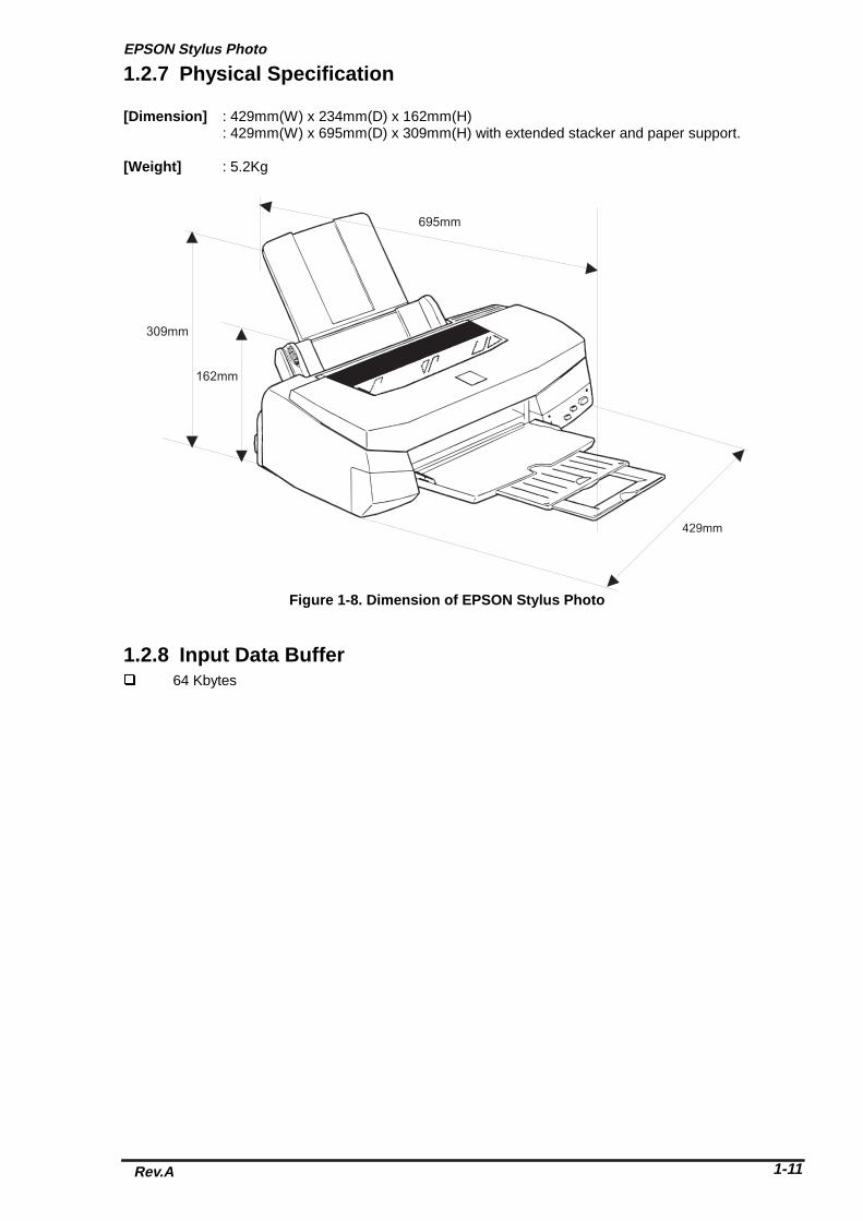
1.2.7 Physical Specification
[Dimension] : 429mm(W) x 234mm(D) x 162mm(H): 429mm(W) x 695mm(D) x 309mm(H) with extended stacker and paper support.
[Weight] : 5.2Kg
1.2.8 Input Data Buffer� 64 Kbytes
695mm
429mm
162mm
309mm
Figure 1-8. Dimension of EPSON Stylus Photo

Chapter 1 Product Description
Rev.A1-12
1.2.9 Electric Specification� 120V version
� [Rated voltage] : AC120V� [Input voltage range] : AC103.5 ∼132V� [Rated frequency range] : 50 ∼ 60Hz� [Input frequency range] : 49.5 ∼ 60.5Hz� [Rated current] : 0.4A(Max. 0.5A)� [Power consumption] : Approx.15W(ISO/IEC 10561 Letter pattern)
: Energy Star compliant� [Insulation Resistance] : 10M ohms min.(between AC line and chassis, DC500V)� [Dielectric strength] : AC1000 V rms. 1 minute or AC1200 V rms. 1 second (between
AC line and chassis)
� 220 ∼ 240V version� [Rated voltage] : AC220V ∼ 240V� [Input voltage range] : AC198 ∼ 264V� [Rated frequency range] : 50 ∼ 60Hz� [Input frequency range] : 49.5 ∼ 60.5Hz� [Rated current] : 0.2 A(Max. 0.3A)� [Power consumption] : Approx.15W(ISO/IEC 10561 Letter pattern)
: Energy Star compliant� [Insulation Resistance] : 10M ohms min.(between AC line and chassis, DC500V)� [Dielectric strength] : AC1500 V rms. 1 minute (between AC line and chassis)
1.2.10 Reliability� Total print volume : 10,000 pages(A4, letter)� Print head life : 2000 million dots/nozzle
1.2.11 Safety Approvals
[120V version]� Safety standard : UL1950 with D3
: CSA22.2 No.950 with D3� EMI : FCC part 15 subpart B class B
: CSA C108.8 class B
[220 - 240V]� Safety standard : EN 60950(VDE,NEMKO)� EMI : EN55022(CISPR Pub.22) class B
: AS/NZS 3548 class B
1.2.12 Acoustic Noise� Noise Level : Approx.45 dB(A) (According to ISO 7779)
1.2.13 CE Marking[220 - 240V version]� Low voltage Directive 73/23/EEC :EN60950� EMC Directive 89/336/EEC :EN55022 Class B
:EN61000-3-2:EN61000-3-3:EN50082-1:IEC801-2:IEC801-3:IEC801-4

EPSON Stylus Photo
Rev.A 1-13
1.2.14 Printer Language and Emulation
� Printer Language : ESC/P Raster: EPSON Remote
� [ESC/P control codes]
< Character mode >� General Operation
� Initialize Printer : ESC@
� Paper feeding� Form Feed : FF� Line Feed : LF� Carriage Return : CR
< Graphic mode >� General operation
� Initialize Printer : ESC@� Unidirectional Printing : ESC U� Print a Image : ESC ACK*� CSF Mode Control : ESC EM
� Paper feeding:� Form Feed : FF� Line Feed : LF� Line Spacing : ESC+� Carriage Return : CR
� Page format� Page Length : ESC(C� Top/Bottom Margin : ESC(c
� Print position motion� Horizontal Print Position : ESC$, ESC\� Vertical Print Position : ESC (V,ESC (v
� Spacing� Define Unit : ESC(U
� Graphics� Graphics Mode : ESC(G� Raster Graphics : ESC.� Microweave control : ESC(i� Dot size control : ESC(e
� Color� Printing color : ESC r, ESC(r
� EEPROM control� EEPROM control : ESC•b

Chapter 1 Product Description
Rev.A1-14
1.3 InterfaceThis printer provides parallel interface and serial interface as standard.
1.3.1 Parallel Interface (Forward Channel)[Transmission mode] : 8 bit parallel, IEEE-1284 compatibility mode[Synchronization] : By STOPBE pulse[Handshaking] : BY BUSY and ACKLG signal[Signal level] : TTL compatible level[Adaptable connector] : 57-30360 (amphenol) or equivalent
BUSY signal is set high before setting either/ERROR low or PE high and held high until all thesesignals return to their inactive state.
BUSY signal is at high level in the following cases.� During data entry (see Data transmission timing)� When input data buffer is full� During -INIT signal is at low level or during hardware initialization� During printer error (See /ERROR signal)� When the parallel interface is not selected
ERROR signal is at low level when the printer is in one of the following states.� Printer hardware error (fatal error)� Paper-out error� Paper-jam error� Ink-out error
PE signal is at high level during paper-out error.
Table 1-9 shows the signal and connector pin assignments for parallel interface(forward channel*1).In case of these signals, twist pair line is used and returning side is connected to signal GND.(*1): Forward channel is the mode when the ordinary data such as an order to print is sent from the PC to the printer.
Pin No. Signal Name Return GND pin In/Out Functional Description1 /STROBE 19 In The strobe pulse. Read-in of data is performed
at the falling edge of this pulse.2-9 DATA0-7 20-27 In The DATA0 through DATA7 signals represent
data bits 0 to 7, respectively. Each signal is athigh level when data is logical 1 and low levelwhen data is logical 0.
10 /ACKNLG 28 Out This signal is a negative pulse indicating thatthe printer can again accept data.
11 BUSY 29 Out A high signal indicates that the printer cannotreceive data.
12 PE 28 Out A high signal indicates paper-out error.13 SLCT 28 Out Always at high level when the printer is
powered on.14 /AFXT 30 In Not used.31 /INIT 30 In The falling edge of a negative pulse or a low
signal on this line causes the printer toinitialize. Minimum 50 us pulse is necessary.
32 /ERROR 29 Out A low signal indicates printer error condition.36 /SLIN 30 In Not used.18 Logic H - Out Pulled up to +5V via 3.9K ohm resistor.35 +5V - Out Pulled up to +5V via 3.3K ohm resistor.17 Chassis GND - - Chassis GND.
16,33,19-30 GND - - Signal GND.15,34 NC - - Not connected.
Note) In/Out refers to the direction of signal flow from the printer’s point of view.
Table 1-9. Signal and Connector Pin Assignment for Parallel Interface

EPSON Stylus Photo
Rev.A 1-15
1.3.2 Parallel Interface (Reverse Channel)
[Transmission mode] : IEEE-1284 nibble mode[Synchronization] : Refer to the IEEE-1284 specification[Handshaking] : Refer to the IEEE-1284 specification[Data trans. timing] : Refer to the IEEE-1284 specification[Signal level] : IEEE-1284 level 1 device
: TTL compatible level[Adaptable connector] : 57-30360 (amphenol) or equivalent[Extensibility request] : The printer responds affirmatively when the extensibility
request values are 00H or 04H, that mean, 00H :Request Nibble Mode Reverse Channel Transfer. 04H :Request device ID; Return Data using Nibble Mode Rev
Channel Transfer.Note) The printer sends following device ID string when it is requested.
<00H> *1 <38H> ContentsMFG EPSON Production MakerCMD ESCPL2,BDC Command systemMDL Stylus[SP]PHOTO Model name *2CLS PRINTER Class
Note*1) [00H] denotes a hexadecimal value of zero.Note*2) MDL value depends on the EEPROM setting. Model name can be changed by changing a
certain address in the EEPROM.
The table below shows pin assignment for reverse channel(*3). In these case of signals, twist pair lineis used and returning side is connected to Signal GND.(*3): Reverse channel is the mode that any data is transferred from the printer to the PC.
Pin No. Signal Name ReturnGND pin
In/Out Functional description
1 HostClk 19 In Host clock signal.2-9 Data0-7 20-27 In The DATA0 through DATA7 signals
represent data bits 0 to7, respectively.Each signal is at high level when data islogical 1 and low level when data islogical 0. These signals are used totransfer the 1284 extensibility requestvalues to the printer.
10 PrtClk 28 Out Printer clock signal.11 PtrBusy, Data Bit-3,7 29 Out Printer busy signal and reverse channel
transfer data bit 3 or 7.12 AckDataReq, DataBit-2,6 28 Out Acknowledge data request signal and
reverse channel transfer data bit 2 or 6.13 Xflag, DataBit-1,5 28 Out X-flag signal and reverse channel
transfer data bit 1 or 5.14 HostBusy 30 In Host busy signal.31 /INIT 30 In Not used.32 /DataAvail, DataBit-0,4 29 Out Data available signal and reverse
channel transfer data bit 0 or 4.36 1284-Active 30 In 1284 active signal.18 Logic-H - Out Pulled up to +5V via 3.9K ohm resister.35 +5V - Out Pulled up to +5V via 3.3K ohm resister.17 Chassis GND - - Chassis GND.
16,33,19-30 GND - - Signal GND.15,34 NC - - Not connected.
Note) In/Out refers to the direction of signal flow from the printer’s point of view.
Table 1-10. Device ID Description
Table 1-11. Pin Assignment for Reverse Channel

Chapter 1 Product Description
Rev.A1-16
Following lists “Notes” when using Parallel Interface.
Note1) “Return GND pin” in the table means twist pair return and is used for all control signalsexcept for Logic H,+5V, Chassis, GND and NC. In this twist pair return, returning sideis connected to GND (16, 33, 19-30 pin) for twist pair return. Also, these cables are shieldedwires and it is effective to connect to each chassis GND in the PC and printer for electrostaticnoise.
Note2) Conditions for Interface are based on TTL level. Rise and fall time should be within 0.2µs.Note3) Refer to the figure 1-9 for transmission timing of each signals.Note4) Do not perform data transmission ignoring /ACK or BUSY signal. (Perform the data transmission
after confirming that /ACK and BUSY signals are Low.)Note5) It is possible to perform the printing test including interface circuit without using equipment
from outside when 8-bit data signal(20-27 pin) is set to appropriate word code and connectthem forcefully to /ACK and /STRB.
[Data Transmission Timing for Forward Channel]
Parameter Minimum Maximumtsetup 500ns ---thold 500ns ---tstb 500ns ---
tready 0 ---tbusy --- 500nstt-out* --- 120nstt-in** --- 200nstreply 0 ---tack 500ns 10us
tnbusy 0 ---tnext 0 ---
* Rise and fall time of every output signals.** Rise and fall time of every input signals.
Typical time of tack is shown below.
Parallel I/F mode Typical time of tackHigh speed 1us
Normal speed 3us
DATA
/STRB
BUSY
/ACK
data byte n data byte n+1
thold
tsetup tstb tnext
tready tbusy
treply tack tnbusy
Min. 500 ns
Min. 500 ns
Min. 500 ns
Min. 500 ns
Max. 500 nsMin. 0
Min. 0 Min. 0
Min. 0
Max. 10 us
tt-out Max. 120 ns : Rise and fall time of every output signalstt-in Max. 200 ns : Rise and fall time of everu input signalsTypical value of tack takes followig values according to Parallel I/F speed(by the settin ofEEPROM 24H).High speed (default) 1 us.Ordinary 3us
Figure 1-9. Parallel Interface Timing Chart (Forward Channel)
Table 1-12. Maximum and Minimum Timing for Data Transmission
Table 1-13. Typical Time of Tack

EPSON Stylus Photo
Rev.A 1-17
[Signal level: TTL compatible (IEEE-1284 level 1 device)]
Parameter Minimum Maximum ConditionVOH* --- 5.5VVOL* -0.5V ---IOH* --- 0.32mA VOH = 2.4VIOL* --- 12mA VOL = 0.4VCO --- 50pFVIH --- 2.0VVIL 0.8V ---IIH --- 0.32mA VIH = 2.0VIIL --- 12mA VIL = 0.8VCI --- 50pF
*A low logic level on the Logic H signal is 2.0V or less when the printer is powered off and thissignal is equal or exceeding 3.0V when the printer is powered on. The receiver shall provide animpedance equivalent to 7.5K ohm to ground.
Table 1-14. Signal Level

Chapter 1 Product Description
Rev.A1-18
1.3.3 Serial Interface
[Standard] : based on RS-423[Synchronization] : Synchronous[Bit rate] : Approx. 900Kbps[Word format] : Start bit 1 bit
: Data bit 8 bit: Parity bit none: Stop bit 1 bit
[Handshaking] : X-ON/X-OFF, DTR protocol[Adaptable Connector] : 8-pin mini circular connector[Recommended interface cable] : Apple System Peripheral-8 cable
Following table shows connector pin assignment and signals:
Pin No. Signal Name In/On Function Description1 SCLK Out Synchronous clock2 CTS In Clear to send3 TxD- Out Transmit data-4 S.G. In Signal ground5 RxD- In Receive data-6 TxD+ Out Balanced Transmit+7 DTR Out Data terminal ready8 RxD+ In Balanced Receive+
Note) In/out refer to the direction of signal flow as viewed from the printer.Following figure shows port arrangement of serial I/F connector.
Following table shows timing relation of DTR, X-on/X-off handshaking.
State Buffer Space X-ON/X-OFF DTRBusy Less than 3072 bytes Send X-OFF code Off
Ready More than 5120 bytes Send X-ON code On
Table 1-15. Connector Pin Assignment and Signals
12
345
678
Figure 1-10. Serial I/F Connector Port
Table 1-16. DTR, X-ON/X-OFF Protocol

EPSON Stylus Photo
Rev.A 1-19
1.3.4 Prevention Hosts from Data Transfer Time-out
Generally, hosts abandon data transfer to peripherals when a peripheral is in the busy state for dozens ofseconds continuously. To prevent hosts from this kind of time-out, the printer receives data very slowly,several bytes per minute, even if the printer is in busy state. This slow down is started when the rest of theinput buffer becomes several hundreds of bytes. Finally, the printer is in the busy state continuously whenthe input buffer is full.
1.3.5 Interface Selection
The printer has 2 built-in interfaces; the parallel interface and serial interface. These interfaces areselected automatically.
� Automatic selectionIn this automatic interface selection mode, the printer is initialized to the idle state scanning whichinterface receives data when it is powered on. Then the interface is that receives data first isselected. When the host stops data transfer and the printer is in the stand-by state for theseconds, the printer is returned to the idle state. As long as the host sends data or the printerinterface is busy state, the selected interface is let as it is.
� Interface state and interface selectionWhen the parallel interface is not selected, the interface got into the busy state. When the serialinterface is not selected, the interface sets the DTR signal MARK. When the printer is initialized orreturned to the idle state, the parallel interface got into the ready state, the serial interface sets theDTR signal SPACE. Caution that the interrupt signal such as the /INIT signal on the parallelinterface is not effective while that interface is not selected.

Chapter 1 Product Description
Rev.A1-20
1.4 Control Panel
EPSON Stylus Photo does not require many buttons since the printer driver can start various settings andmotions. Therefore, there are only 2 non-lock type push buttons, 1 lock type push button and 4 LEDs.Following figure shows control panel of EPSON Stylus Photo.
1.4.1 Indicators
(1) PowerLights when the operate button is “ON”, and AC power is supplied.
(2) Paper outLights during the paper-out condition, and blinks during the paper-jam condition.
(3) Ink Out (Black)Lights during no Black ink condition, and blinks during the Black ink low condition.
(4) Ink Out (Color)Lights during no Color ink condition, and blinks during the Color ink low condition.
Paper out LED:Red
Ink Out (Black)LED :Red
Ink Out (Color) LED: Red
Cleaning button
Load/Eject button
Power SW
Power LED :Green
Figure 1-11. Control Panel

EPSON Stylus Photo
Rev.A 1-21
1.4.2 Panel Functions
[Panel Functions]
Button FunctionLoad/Eject
(Pushing within 2 seconds)• Loads or Ejects the paper.
• When carriage is on the Ink Cartridge change position, return carriagefrom Ink Cartridge change position.
Load/Eject(Pushing for 2 seconds)
• Starts the Ink Cartridge change sequence.*Moves the carriage to cartridge change position.
Cleaning(Pushing for 2 seconds)
• Starts the Cleaning of head.
• In the condition of “Ink Low” or “Ink Out” or “No Ink Cartridge” starts theInk Cartridge change sequence.*
Cleaning(Pushing within 2 seconds)
• When carriage is on the Ink Cartridge change position, return carriagefrom Ink Cartridge change position.
*This function is not available in printing status.
[Panel Functions with Power ON]
Button FunctionLoad/Eject • Starts status printings.**Cleaning • Changes a Code Page.
Load/Eject+
Cleaning
• Enters the particular settings mode.(Factory use only.)
• To enter the particular settings mode, it is necessary to push followingbutton while Paper Out LED is blinking.(It blinks about 5 seconds)
** status printings prints firmware version, ink counter, selected code page and nozzle check patterns.
[Particular setting mode]
Button FunctionLoad/Eject
(Pushing for 10 seconds)• Initialize EEPROM*** and reset timer IC.
*** Refer to EEPROM map.(Refer to EEPROM map in the Appendix)
Table 1-17. Panel Function
Table 1-18. Panel Function with Power On
Table 1-19. Particular Setting Mode

Chapter 1 Product Description
Rev.A1-22
[Maintenance Error Reset Procedure]You can reset the maintenance error by pressing the cleaning button after you enter the particular settingmode(Refer to table 1-18, 19). There are no function which can be reset the all address in EEPROM onthe EPSON Stylus Photo. Following are detail procedure of maintenance error reset operation
[Step 1] By pushing Load/Eject and Cleaning buttons at the same time, turn on the power switch.(By operating this performance, the LED for paper out starts blinking.(5 seconds only) )
[Step 2] Push the Load/Eject button for 10 seconds while the LED for Paper Out is blinking.
Note) If the printer accepts this function correctly, it returns to the standby mode after theMaintenance LEDs (both black and CMYcm) blink for 1 second.Following shows the lists that will be cleared by this performance.
1. Clear the value of Ink Counter2. Clear Time IC3. Initialization of I/F selection (returns to AUTO)
WARNING
� Since EPSON Stylus Photo does not have “All Clear function” for EEPROM like other printers, donot perform this operation except for the purpose of the maintenance error reset.
� Be sure to replace a waste ink pad in the printer enclosure with a new one after you perform[Maintenance error reset procedure].
� If the waste ink pad is replaced regardless of maintenance error, perform this operation.
1.4.3 Printer Condition and Panel Status
The table below shows printer condition and panel status. Since this table shows various error status andalso presents printer status, you can judge appropriate repair ways from this table.
IndicatorsPrinter status Power Ink Out
(Black)Ink Out(Color)
Paper Out Priority
Power on condition On --- --- --- 9Ink sequence Blink --- --- --- 6Ink Cartridge changemode
Blink --- --- --- 5
Data processing Blink --- --- --- 8Paper Out 1* --- --- --- On 4Paper jam condition1* --- Off Off Blink 3No Ink cartridge or Inkend(black)1*
--- On --- --- 7
Ink level low(black) --- Blink --- --- 7No Ink cartridge or Inkend(color)1*
--- --- On --- 7
Ink level low(color) --- --- Blink --- 7Enter EEPROM andTimer IC reset 2*
--- On(1 second only)
On(1 second only)
On(1 second only)
---
Maintenance request1* Blink Blink Blink Blink 2Fatal error1* Blink On On Blink 1
Note1*): Refer to section 1.5 for error status.Note2*): It does not mean that all address would be cleared.Note3*): --- means no changes.
Table 1-20. Printer Condition and Panel Status

EPSON Stylus Photo
Rev.A 1-23
1.5 Error Status
When following status occur, the printer goes to the error status and stops taking data, setting the/ERROR signal in the interface as “Low”, and Busy signal as “High”. At this time, the printer goes to nonprintable status. Refer to section 1.4.3 for more details of LED Panel indicators during the various errorstatus.
1.5.1 Ink Out
When the printer runs out most part of the ink of any one color, it warns ink-low and keeps printing. Whenthe printer runs out the whole ink of any one color, it stops printing and indicates ink-out error. User isrequested to install a new ink-cartridge in this state. A ink-cartridge once taken out should never be usedagain. Re-installation of the cartridge not filled fully upsets the ink level detection and may cause a seriousproblem in the print head as a result.
WARNING
� Never use the ink cartridge once taken out.
Following explains above warning sign.
[Step 1] After the cartridge is once taken out, bubbles come in from the ink supply hole located atthe top of cartridge and are absorbed into the head during printing performance.Therefore, the head will be unable to discharge the ink properly. Also, inevitableentering of bubbles when installing a new ink cartridge can be absorbed to ink itself sincethe ink itself in the cartridge is deaerated during the production process.However, this absorbing ability can last only about one hour after the cartridge is installed.
[Step 2] Even after the bubble absorbing ability described above stops, there is no worry aboutentering bubbles as long as the ink cartridge is being installed to the printer.However, if the ink cartridge which does not have absorbing ability any more is onceremoved from the printer, new coming bubbles into the cartridge will never disappearnaturally. These bubbles may cause not only printing malfunction but also thickening ink.This thickened ink goes into the head and clogs ink path in the head or nozzle and maycause serious head damage.
[Step 3] As standard specification for EPSON Stylus Photo, ink consumption counter is reset whenthe ink cartridge is removed. If an ink cartridge is removed and re-installed unnecessarilythe value on the ink consumption monitor which the user can check will be wrong andprinter may keep printing even though the ink cartridge is installed empty.This may cause head damage.
1.5.2 Paper Out
When printer fails to load a sheet after power on operation including timer-cleaning is done and Load/Ejectbutton on the FF command or operation panel is pressed, it goes paper out error.
1.5.3 Paper Jam
When the printer fails to eject a sheet even after feeding motion is completed or Load/Eject button on theFF command or operation panel is pressed, it goes paper jam error.

Chapter 1 Product Description
Rev.A1-24
1.5.4 No Ink-Cartridge
Following reasons can be the causes when printer goes to this error mode.
1) When the printer is turned on for the first time.(This is a normal error state and it returns to the normal state after installing an ink cartridge accordingto the ink cartridge exchange operation.)
2) Ink cartridge exchange operation is not done correctly.After the position of carriage is moved by exchange operation, if the cleaning button is pushed withoutinstalling ink cartridge or if the carriage returns to the home-position automatically without doing anyoperation, it is considered as handling mistake. However, it returns to normal state by performingink exchange operation again and installing cartridge correctly.
3) If “No ink-cartridge error” appears even after the ink cartridge is installed, the printer must besomething wrong and around the sensor area in the carriage need to be repaired.
4) If sometimes printer can print normally but also sometimes “No ink-cartridge error” appears, theprinter must be something wrong. (Same reason as 3) above)
1.5.5 Maintenance Request
When the total quantity of ink wasted through the cleanings and flushing reaches to the limit, printerindicates this error and stops. The absorber in the printer enclosure is needed to be replaced with newone by a service person. The ink quantity that is absorbed by the absorber (waste ink pad) is monitored bythe software counter as “total ink counter”. This counter is added by point system and also absorber’smaximum ability is set at the following reference value.
37000 X 0.0113 ml = Approximately 418 ml
� 1-point = 0.0113ml (the value which is multiplied evaporating rate and 1-dot ink weight 0.02ml)� 37000 = Maximum point number (Maintenance error threshold)
However, considering dispersion of ink absorbing quantity and the number of using nozzles, ink total valueis calculated by the following formula.
418 X 1.1/ 67% = 526 ml (but up to 687ml can be retained)
When you perform self test after completing repairs, it is possible to check the present value of totalink counter conditions of all nozzles by performing status printing in the built-in function. Therefore,make sure that the printer has enough value of total ink counter (if the number is close to 29500 ornot). If there is not enough value, the service man is required to judge if it is necessary to clearEEPROM after replacing the absorber (waste ink pad) or not. Refer to section 1.4.2 if you need toperform EEPROM Clear.
1.5.6 Fatal ErrorsWhen printer detects fatal errors such as carriage control error or CG access error, it goes to thiserror mode. Refer to followings for each error.
1) Carriage control Error : Parallel adjustment malfunction, HP detection malfunction, shortage of lubricant on the carriage guide shaft, etc.
2) CG Access Error : Short circuit, etc.
WARNING

EPSON Stylus Photo
Rev.A 1-25
1.6 Printer InitializationEPSON Stylus Photo has three kinds of initialization methods. Following explains each initialization.
[1.Power-on initialization]This printer is initialized when turning the printer power on, or printer recognized the cold-reset command(remote RS command). When printer is initialized, following action is performed.
(a) Initializes printer mechanism.(b) Clears input data buffer.(c) Clears print buffer.(d) Sets default values.
[2.Operator(Panel) initialization]This printer is initialized when turning the printer power on again within 10 seconds from last power off, orprinter recognized the /INIT signal (negative pulse) of parallel interface. When printer is initialized,following action is performed.
(a) Cap the printer head.(b) Eject a paper.(c) Clears input data buffer.(d) Clears print buffer.(e) Sets default values.
[3. Software initialization]The ESC@ command also initializes the printer. When printer is initialized, following action is performed.
(a) Clears print buffer.(b) Sets default values.
1.7 Initialization Settings
EPSON Stylus Photo initializes following settings when the initialization is performed. Also, if the userchanges the settings in the Panel setting, Default setting or Remote command setting, values or settingswhich are possible to be stored are initialized as initialization settings.
� Page position : Page heading location as present paper location� Line spacing : 1/6 inch� Right margin position : 80 lines� Left margin position : first line� Character pitch : 10CPI� Printing mode : Text mode (Not Raster graphics mode)
Chapter 1 Product Description
Rev.A1-26
1.8 Main Components
EPSON Stylus Photo has following major units. Also, it is one of the major characteristics that the bottomof the Printer mechanism plays the role as Lower case at the same time. Each units from 2) to 4) aresimply explained as following.
1) C209 Main control board2) C206 PSB/PSE(Power Supply Board)3) C209 PNL(Panel Board)4) Printer Mechanism5) Upper Case
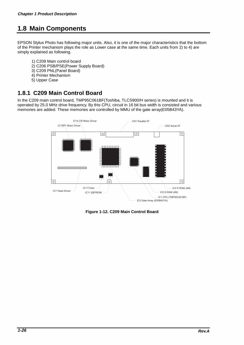
1.8.1 C209 Main Control BoardIn the C209 main control board, TMP95C061BF(Toshiba, TLCS900/H series) is mounted and it isoperated by 25.0 MHz drive frequency. By this CPU, circuit in 16 bit bus width is consisted and variousmemories are added. These memories are controlled by MMU of the gate array(E05B43YA).
IC3 P-ROM (4M)
IC5 D-RAM (4M)
IC1 CPU (TMP95C061BF)
IC7 Head DriverIC11Timer
IC11 EEPROM
IC2 Gate Array (E05B43YA)
CN2 Serial I/F
CN1 Parallel I/FIC14 CR Motor Driver
IC15PF Motor Driver
Figure 1-12. C209 Main Control Board

EPSON Stylus Photo
Rev.A 1-27
1.8.2 C206 PSB/PSE(Power Supply) Board
The C206 PSB/PSE board is a switching regulator type power supply unit and constantly supplies stablelogic and power voltages to the printer mechanism and the main control board. Also, since this C206PSB/PSE board has the power switch in the secondly side of the circuit, it is possible to keep supplyingelectricity to the C209 MAIN control board for 30 seconds even after the power switch is turned off. Usingthis time difference, even when mis-operation is done by the user such as turning off the power during themiddle of printing work, it prevents unexpected trouble with the printhead from occurring, by transferringthe printhead to the cap position before complete shut down. The C206 PSB Board is for AC100 - 120Vinput voltage and the C206 PSE Board is for AC220-240V input voltage.
1.8.3 C209PNL Panel Unit
Panel unit (C209 PNL board) consists of 3 switches, 4 LEDs and 1 connector as they are illustrated in thefigure below.
1.8.4 Printer Mechanism
This printer mechanism consists of ASF(auto sheet feeder) mechanism, paper load mechanism,carriage mechanism, print head, pump mechanism and waste ink absorber.
L1 Filter
F1 Fuse Q1 Main FET
T1 Maintrans
CN1 AC Input
PC1 Photo Coupler for PowerSupply Control
C11 Smoothing ElectrolyticCapacitor
CN1 Power Output
Figure 1-13. C206 PSB Board
Paper Out LED
Ink Out(Black) LED
Ink Out(Color) LED
Cleaning SW
Load/Eject SW
Power SW
Power LED
Figure 1-14. C209 PNL Panel Unit

Chapter 1 Product Description
Rev.A1-28
1.8.5 HousingThis printer’s housing consists of upper case, print cover, paper support and paper eject tray.In this printer, there is no lower case since the printer mechanism plays its role.
Upper Case
Printer Cover
Paper Support
Figure 1-15. Housing

Chapter 2Operating Principles
2.1 OVERVIEW ............................................................................................................2-1 2.1.1 Printer Mechanism ........................................................................................................ ......... 2-1
2.1.1.1 Printing Mechanism................................................................................................... 2-2 2.1.1.1.1 Printing Process ............................................................................................. 2-3 2.1.1.1.2 Printing Method .............................................................................................. 2-4
2.1.1.2 Carriage Mechanism ................................................................................................. 2-7 2.1.1.2.1 Paper Gap Adjust Mechanism ..................................................................... 2-10
2.1.1.3 Paper Feed Mechanism and Pump Mechanism ......................................................2-11 2.1.1.4 Ink System............................................................................................................... 2-14
2.1.1.4.1 Pump, Carriage Lock, Head Cleaner Mechanism........................................ 2-15 2.1.1.4.2 Cap Mechanism ........................................................................................... 2-17
2.2 Electrical Circuit Operating Principles .............................................................2-18 2.2.1 C206 PSB/PSE Power Board ............................................................................................... 2- 18
2.2.2 C209 Main Board .......................................................................................................... ........ 2-20 2.2.2.1 Reset Circuits .......................................................................................................... 2-21 2.2.2.2 Sensor Circuits ........................................................................................................ 2-22 2.2.2.3 EEPROM Control Circuits ....................................................................................... 2-23 2.2.2.4 Timer Circuit ............................................................................................................ 2-24 2.2.2.5 Print Head Drive Circuit ........................................................................................... 2-25 2.2.2.6 Motor Drive Circuits................................................................................................. 2-27
2.3 Ink System Control .............................................................................................2-28 2.3.1 Ink System Basic Functions............................................................................................... . 2-28
2.3.2 Timers and Counters...................................................................................................... ...... 2-29
2.3.3 Ink System Sequence...................................................................................................... ..... 2-30

Chapter2 Operating Principles
Rev. A 2-1
2.1 OVERVIEWThis section describes Printer Mechanism, electric circuit board (C206 PSB/PSE, C209 Main, C209PNLboard) of EPSON Stylus Photo.
2.1.1 Printer Mechanism
Unlike the previous EPSON Ink Jet printers, printer mechanism of EPSON Stylus Photo does not haveexclusive mechanism to change over paper feeding and pumping operation. In stead, this control is doneby the turning direction of paper feed/pump motor and changing the position of carriage at that time.Also, unlike previous print heads, the print head of this printer became one unit combined with black,CMY(Cyan, Magenta, Yellow), LM(Light Magenta) and LC(Light Cyan) head. Black head has 32 nozzles,90 dpi(vertical direction) and CMY, LC, LM head has 32 nozzles for each color, 90 dpi (vertical direction).Also, since these print head is driven by frequency 14.4KHz, this printer can print twice faster (200-dpi)than Stylus Color even at 720-dpi high resolution printing. Since the head drive frequency of Stylus Colorwas 7.2KHz, it was driven by 100-cps printing speed in order to perform 720-dpi printing.Following figure2-1 shows outline of the printer mechanism.
Platen Drive Mechanism
Paper Pickup Mechanism
Pump Drive Mechanism
Carriage Motor
Paper Feed Motor
Paper Pick Up Trigger Lever
Carriage Unit(Prinr Head Unit)
Timing Belt
Pumping Position
Figure 2-1. EPSON Stylus Photo Printer Mechanism Block Diagram

EPSON Stylus Photo
Rev. A2-2
As you can see major printer mechanisms in the figure 2-1, there are four major mechanisms as they arelisted below.
1) Printing mechanism 2) Carriage drive unit 3) Paper pick up mechanism 4) Pump drive mechanism
2.1.1.1 Printing Mechanism
Basic operating principles of the print head which plays major role of printing mechanism is the same asprevious models; on demand type MACH head method, but there is some differences in the resolution.(Refer to figure1-1) Also, unlike Stylus Color II, Stylus 820 and Stylus Color 200 automatic correction type,in order to fix the dispersion of mufti layer piezo electric element which is used for driving each nozzles, itis necessary to input the VH value written on the side of print head by using exclusive program when youreplace the print head, control board, or the printer mechanism.(However, there are no resistor array todecide the VH voltage on the main control board.) Following explains the print heads.
� PZT� PZT is an abbreviation of Piezo Electric Element. Print signal from C209 board is sent through the
driver board on the print head unit and to the PZT. Then, the PZT pushes the top cavity which hasink stored, and make the ink discharge from each nozzle located on the nozzleplate.
� Cavity Set� Ink which is absorbed from ink cartridge go through the filter and will be stored temporarily in this
tank, which is called “cavity”, until PZT is driven.� Nozzle Plate
� The board with nozzle holes on the printer head surface is called Nozzle Plate.� Filter
� When the ink cartridge is installed, if any dirt or dust around the cartridge needles areabsorbed into the head inside, there is a great possibility of causing nozzle clog anddisturbance of ink flow and finally causing alignment failure and dot-missing. In order toprevent this, filter is set at cartridge needle below and ink is once filtered here.
Cartridge needle
Filter
Cavity set
Printhead driver board
PZT
Nozzle Plate
Ink Supply Tube
Ink Cartridge SensorActuator
(Ink Cartridge)
Figure 2-2. Print Head Sectional Drawing

Chapter2 Operating Principles
Rev. A 2-3
2.1.1.1.1 Printing Process
Following figures indicate the sectional drawing of normal state and ejecting state of print head.
(1) Normal State:When the printing order is not output, PTZ also does not move and stays in the waiting mode(normal state).
(2) Ejecting State:When the print signal is output from the C209 main board, IC(IR2C72C and IR2C73C:Nozzle
Selector) located on the print head unit latches the data once by 1-byte unit. Appropriate PZT latched by nozzle selector is pushed in to the cavity by applying common voltage from the C209 main board. By this operation, ink that is stored in the cavity pops out from nozzles.
Nozzle Nozzle Plate
PZTInk Course
Cavity
Figure 2-3. Print Head Normal State
Figure 2-4. Print Head Ejecting State

EPSON Stylus Photo
Rev. A2-4
2.1.1.1.2 Printing Method
This section explains printing method of actual printing such as printing text at various resolutionselect/printing mode and graphics printing. In order to prevent white or color banding which are peculiarproblem of ink-jet, new Micro-Weave functions are added to the previous Micro-Weave function. Thenumber of nozzles and printing mode according to the selected resolution are used separately by a user.The table below shows relation between selected resolution and printing mode.
1) Full Overlap Micro-Weave2) Part Line Overlap Micro-Weave3) Micro-Weave: (same as previous control)
Verticaldirection
[dpi]
Printingmode
Paper feedpitch[inch]
ForwardOverlap-Nozzle
NonOverlap-Nozzle
BackwardOverlap-Nozzle
Not usedNozzle
360 FOL M/W 15/360 #16•` #30 --- #1•` #15 #31, #32M/W 31/360 --- #1•` #31 --- #32
720 FOL M/W 15/720 #16•` #30 --- #1•` #15 #31, #32POL M/W 29/720 #30•` #32 #4•` #29 #1•` #3 ---
Note1: M/W means Micro-Weave. Note2: FOL means Full Overlap Micro-Weave. Note3: POL means Part line Overlap Micro- Weave. Note4: Forward Overlap-Nozzle and backward Overlap -Nozzle are described in the [1.Full Overlap
Mirco-Weave] and [2.Part line Overlap Micro-Weave] below.
Following explains operation outlines of new Micro-Weave functions listed above.
[1. Full Overlap Micro-Weave]
In order to print one line at horizontal direction, this printing method is designed to complete a printingpattern by two-pass carriage operation with two different types of dot. When these two different types ofdot pass one same line twice, it does not print the same dot twice. Following explains the outline of thismovement.
� The number of all nozzles which are going to be used are divided equally into 2 groups.� Paper feeding will be done as many as each number of nozzles which are divided into two groups
and the same number of dots.(for example, if there are two 10-nozzle groups during 360-dpiprinting at longitudinal direction, paper feeding of 10/360-inch becomes available.)
� At this time, two groups perform Micro-Weave individually and particular lines are passed bytwo different nozzles.
Note1) Two groups which are divided according to each elements will be divided either even dot orodd dot when particular lines(level direction line) are formed and eventually, these lines will becompleted at selected resolution. Following is a conceptual figure when full overlap micro-weave forms a particular line.
Table 2-1. Resolution and Printing Mode
Nozzle No.#9
Nozzle No.#4
360-dpiParticular line(Completed line)
Condition: 360-dpi printingNozzle: Total 10 nozzle/each color
Figure 2-5. Full Overlap Micro-Weave

Chapter2 Operating Principles
Rev. A 2-5
Note 2) The way firmware decides which nozzle becomes even dot or odd dot is determinedas it is described below.
� If the line which is about to be printed is even line:� First dot prints odd dot lines and 2nd dot prints even dot lines.
� If the line which is about to be printed is odd line:� 1st dot prints even dot lines and 2nd dot prints odd dot lines. Eventually, horizontal resolution
will be the same resolution as selected one.
[2.Part Line Overlap Micro-Weave]
This printing method is to perform Micro-Weave printing, overlapping part of nozzles which areused for printing. As a result, a part of line which is overlapped consists of different browse withdifferent nozzles. The figure below shows 1-line overlap at 5-dot sending as an example withexplanation on the next page.
#1#2#3#4#5#6
Pass1
2
3
45
6
7
8
9
10
11
Raster 10
Raster 1
Note1: The paper feed pitch is 5/360-dpi in this figure.Note2: Mark of and mean overlap nozzle.
Figure 2-6. Part line Overlap Micro-Weave

EPSON Stylus Photo
Rev. A2-6
� The difference between Full-Overlap Micro-Weave and Part line Overlap Micro-Weave arefollowing;
� Full-Overlap Micro-Weave:Printing is performed, judging if nozzles are even or odd dot by 2 different dots in all
different lines.
�� Part line Overlap Micro-Weave:After particular nozzles(only#1, and #6 in the figure2-6) are determined as overlap nozzles,even or odd dot will be determined like Full-overlap Micro-Weave does.(Forward Overlap Nozzle is determined as even and backward nozzle is odd.)Also, nozzles other than particular nozzles can print at even and odd dot just by onenozzle.
1) Overlap Nozzle : Head drive frequency is driven half of the ordinal one like 2) below.2) Nozzle other than Overlap nozzle : Head drive frequency is twice as much as overlap nozzle.
Usually, the firmware changes over automatically these full overlap Micro-Weave, Part line OverlapMicro-Weave, and ordinal Micro-weave according to the selection of resolution. Also, when these threeprinting modes are performed by the EPSON Stylus Photo, the printer performs top and bottom marginprocess in order to control the overprinting volume as little as possible.

Chapter2 Operating Principles
Rev. A 2-7
2.1.1.2 Carriage Mechanism
Carriage mechanism is to drive the carriage with print head from left to right or vice versa.The carriage drive motor in this printer is a 4-phase, 200-pole stepping motor and is driven by1-2phase, 2-2phase and W1-2phase drive method. This stepping motor allows the carriage tomove freely to the particular positions which is necessary for various operation, such as paper feeding,ink absorbing, flashing, ink exchange and cleaning operations. The tables below show carriage motorspecifications and motor controls at each mode.
Item DescriptionMotor type 4-phase/200-pole Stepping motorDrive voltage Range 42VDC ±5%Internal coil resistance 7.8 Ohms ±10%
(per phase under 25°C environment)Driving speed(frequency) range[cps (pps)] 5(60) - 340(4080)Control method Bi-Pola Drive
Mode Driving speed[CPS]
Drive frequency[PPS]
Drive method
High speed skip 340 4080 W1-2, 2-2,1-2phase drive*Printing(1→ 80 column direction) 200 2400 W1-2phase drivePrinting(80→ 1 column direction) 200 2400 W1-2phase driveCapping 80 960 W1-2phase driveWiping 40 480 W1-2phase driveCap(valve released) 20 240 W1-2phase driveCap (Release) 5 60 W1-2phase drive
*Note 1): The reason why plural drive methods exist is that following some sequences described belowexist in the each mode and, more stable carriage operation and printing are performedindividually by different drive methods. This drive method is necessary especially for highspeed skip.
Acceleration 1 mode → Acceleration 2 mode → Deceleration 1 mode → Deceleration 2 mode
Table2-2. Carriage Motor Specification
Table 2-3. Motor Control at each mode
Rotor
A
/A
/B
B
C209 MAIN BoardCN6(CN7)
1
3
2
4
Figure 2-7.CR(PF/Pump) Motor Internal Block Diagram

EPSON Stylus Photo
Rev. A2-8
The table below shows W1-2 phase drive sequence at each steps when the rotor of carriage motormakes one rotation. In the EPSON Stylus Photo, in addition to a function that printing is performed withW1-2 drive phase, high speed skip mode which is a function to skip over the blank from the end of theprinting data to the next data starting point in high speed, can be also performed by 2-2 and 1-2 phasedrive. W1-2 phase requires 4 times as much steps as 2-2 phase drive, calculating 2-2 phase as standard.By using this method, it becomes possible to supply constant and stable torque to the motor. As a result, italso becomes difficult to be influenced by vibration from the printer mechanism during printing.
SequenceNumber
Phase A Phase B
Phase a 10a l1a CurrentDuty
Phase b 10b l1b CurrentDuty
0 0 1 0 +2/3 0 1 0 +2/31 0 0 1 +1/3 0 0 0 +12 X 1 1 0 0 0 0 +13 1 0 1 -1/3 0 0 0 +14 1 1 0 -2/3 0 1 0 +2/35 1 0 0 -1 X 0 1 +1/36 1 0 0 -1 1 1 1 07 1 0 0 -1 1 0 1 -1/38 1 1 0 -2/3 1 1 0 -2/39 1 0 1 -1/3 1 0 0 -110 X 1 1 0 1 0 0 -111 0 0 1 +1/3 1 0 0 -112 0 1 0 +2/3 1 1 0 -2/313 0 0 0 +1 1 0 1 -1/314 0 0 0 +1 X 1 1 015 0 0 0 +1 0 0 1 +2/3
This W1-2 phase drive (or 2W1-2 phase drive) is called Micro-step and is attached with so called2/3•E Vref or 1/3•E Vref factor, compared with drive current value (Vref100%) which is supplied at 2-2phase drive. This Micro-Step allows the rotor to have delicate rotation. In the 2-2 phase drive method, itis usuallyrequired to take 4-step sequence in order to rotate the rotor once. However, in case of W1-2 phase,it is required to take 16-step sequence(in the table 2-4, sequence 0•` 15) which is 4 times more than2-2 phase method to do that. Also, in case of 2W1-2 phase drive which can be seen in the Stylus Coloretc., it takes 2-step to rotate the rotor once. The table below shows relation of rotation direction of the rotorand carriage proceeding direction.
Carriage proceedingdirection
Rotation direction ofRotor 1*
Drive method Proceeding order ofsequence
HP→80 column direction Clockwise direction 2-2, 1-2, W1-2 phase Sequence No.0→1580 column→HP direction Counterclockwise
direction2-2, 1-2, W1-2 phase Sequence No.15→0
Note) 1* Looking from rotor shaft side.
Table 2-4.Motor Drive Sequence(W1-2.phase drive)
Table 2-5. Relationship Between Rotation Direction and Carriage Operation

Chapter2 Operating Principles
Rev. A 2-9
The figure below shows carriage mechanism. The print head as a core of the printing mechanism isinstalled in the carriage unit. This print head keeps the angle of print head in flexible and adjustablestructure by moving the adjustment lever up and down with the Angular adjustment mechanism.(Refer to chapter 4 for more details) Also, parallelism adjustment lever is mounted on right side of thecarriage guide shaft and it adjusts parallelism between paper and shaft when this shaft is installed to theprinter mechanism.After this adjustment is completed, operating the PG adjustment lever makes possible to change thespace between the surface of paper and print head surface into 2 phases; either 1.04mm to 1.94mm. It ispossible to vary the space between the surface of paper feed assembly and the print head by rotating theaxis of carriage guide shaft which itself is decentralized, with the operation of PG lever. This is themechanism that user can adjust the appropriate PG value by himself according to the paper thickness orany other environmental conditions such as paper curl.
Carriage lock mechanism is to prevent the carriage from being left uncapped for a long time because ofvibration during the printer transport or mishandling by the users. If the carriage is left uncapped for a longtime, an ink on the print head surface gradually becomes viscosity. As a result, the nozzle will be unable todischarge ink. To make matters worse, the nozzle may be completely clogged by the viscosity ink and itmay not be able to return to the normal condition just by the normal cleaning operation. In order to preventthis, printer goes to carriage lock state at the following conditions.
� After Power OFF operation:� If the power is turned off during the printing or any other performance, carriage lock will be
performed in the end after completing initialize operation.� After power ON operation:
� After power is turned on and automatic P-On Cleaning(power on cleaning) is performed, thencarriage lock will be performed. The timer IC always counts printer’s power OFF time by usingthe power of lithium battery mounted on the C209 main board. P-on cleaning function automatically selects the cleaning level according to the time which the printer is not in used.
� After Eject the paper: After Load/Eject button is pressed and the paper is ejected, if the data is not input, the printer
performs carriage lock and goes to standby state. However, if the paper is loaded to the printer inside by Load/Eject button, the printer does not perform the carriage lock operation.
Carriage home position SensorCarriage Motor
Timing BeltPF Roller
Paper Feed Motor
Eject Roller Paper guide(Front)
Carriage Unit
Front Side Rear Side
Parallelism Adjust Lever
Carriage Guide Shaft
Fixing Bush
Figure 2-8. Carriage Mechanism(Top Viewing)

EPSON Stylus Photo
Rev. A2-10
2.1.1.2.1 Paper Gap Adjust Mechanism
This mechanism can be set by the users and can prevent various problems related to low image densityor print with any dirt by changing the positions of PG lever according to the paper types.
Paper Lever Position PG ValueNormal paper,Coated paper
Front 0 mm(1.04mm between head and paper feed
assembly)Envelopes Rear 0.9mm
(1.94mm between head and paper feedassembly)
It is a major premise that parallelism adjustment is done correctly for the space between head and paper(PG value above) which can be changed by adjusting the paper gap.Parallelism adjustment should be done when the serviceman mounts the carriage guide shaft on theprinter mechanism during repair service. In the adjustment, the space should be adjusted to 1.04 mm,using a thickness gauge.
Table 2-6. PG Lever Setting

Chapter2 Operating Principles
Rev. A 2-11
2.1.1.3 Paper Feed Mechanism and Pump Mechanism
Mechanisms that send the paper in the hopper to inside the printer and perform constant paperfeed in order to perform printing on the sent paper are called paper feed mechanism as generic name.In the EPSON Stylus Photo, 4-phase, 200-pole hybrid type pulse motor is used in the PF motor as amotive power for the paper mechanism and driving is done at 2-2 and 1-2 phase drive method.This motor is not only used as a power source for paper feed mechanism but also used as power sourcefor pump mechanism which is necessary for the print head cleaning. By using this pulse motor, it becomespossible to use high speed drive or intermittent drive for the various paper feeds and pump operations,such as paper feed, slight paper feed, high and low speed absorption of pump operations. Followingtables(Table 2-7 and 2-8) show PF motor specifications and control method at each mode.
Item DescriptionMotor type 4-phase/200-pole Stepping motorDrive voltage 42VDC±5%Coil Resistance 7.8 ohms±10%
(per 1 phase under 25°C environment)Drive frequency 400-4320HzControl method Bi-Pola Drive
Mode Drive Method Drive Frequency[Hz]
Pulse Space(ƒÊs)
Paper feed A 2-2 phase 4320 231Slight paper feed 1-2 phase 400 2500Slight paper feed 1-2 phase 2400 417High speed attraction of pump 2-2 phase 4100 243Low speed attraction of pump 1-2 phase 1800 555Low speed paper feed 1-2 phase 1200 833Paper feed B 2-2 phase 3400 294Paper feed C 1-2 phase 4000 250Ordinal absorption of pump 1-2 phase 4100 243
Following tables show 1-2phase drive method at PF motor drive and each drive sequence at 2-2phasedrive method.
Step No. Clockwise Counter clockwise
Phase A Phase B Phase A Phase B1 +2/3 +2/3 +2/3 +2/3
0 +1 +1 02 -2/3 +2/3 +2/3 -2/3
-1 0 0 -13 -2/3 -2/3 -2/3 -2/3
0 -1 -1 04 +2/3 -2/3 -2/3 +2/3
+1 0 0 +1
Step No. Clockwise(CW) Counter clockwise(CCW)
A B A B1 +2/3 +2/3 +2/3 +2/32 -2/3 +2/3 +2/3 -2/33 -2/3 -2/3 -2/3 -2/34 +2/3 -2/3 -2/3 +2/3
Table 2-7. PF Motor Specification
Table 2-8. Motor Control Method at Each Mode
Table 2-9. 1-2 Phase Drive Method
Table 2-10. Drive Sequence at 2-2 Phase Drive

EPSON Stylus Photo
Rev. A2-12
Papers on the ASF (auto-sheet-feeder) supplied by the user are carried to the printer inside by paperpick up sequence. Unlike the previous models, ASF of EPSON Stylus Photo has multi feed preventionmechanism. Following explains this function and figure below shows its mechanism.
[1. Multi feed prevention mechanism]When the Load/Eject button is pressed, reversed rotation of PF motor is performed.The return lever resets papers which are already in the out of stand by position and make it possible toperform stable paper feeding by picking up the paper again.
Following explains process of multi feed prevention step by step. Refer to the figure above and confirmits operation.
[Step 1] When the Load/Eject button is pressed or the signal of printing order is input from the PC, PF motor rotates counterclockwise and makes the CAM rotate towards direction of 1) in the figure above.[Step 2] When the CAM covers the notch by the return lever, that position is considered as home
position, being monitored by ASF sensor.[Step 3] When the CAM rotates toward 1) in the figure above, the return lever is pushed by the notch
of CAM and falls towards 2). At this time, the return lever moves to direction 3) by thismotion, and push down the pad which is waiting in the below part. At this time, friction ofpinch roller and pad will be canceled.
[Step 4] The papers which are out of stand by position by the previous paper feed motion arereturned to the paper stand by position by flip over strength of return lever. After this,PF motor rotates clockwise and the printer goes to pick up sequence.
Return Lever
Pad spring
Hopper spring
Hopper
Pintch Roller
D-Cut Roller CAM
[Standby state] [Returning state]
1)
2)
Pad
3)
Figure 2-9. Multi Paper Feed Prevention Mechanism

Chapter2 Operating Principles
Rev. A 2-13
In the paper pick up mechanism of EPSON Stylus Photo, same mechanism as Stylus Color IIs/820are applied. This mechanism changes adjoined lines of gear by colliding trigger lever with carriageunit, and convey the motive power on the paper feed assembly to the ASF side(paper roller). The figurebelow shows mechanism with explanation.
[2. Paper pick up mechanism]When the Load/Eject button is pressed or printing order is input, the carriage unit moves tothe left edge and collides with paper pick up trigger lever. When the carriage collides with this triggerlevel, a planetary gear located on the same axis is also pushed at the same time and conveysthe motive power on the paper feed assembly to the adjoined gear line side for ASF drive.
[3. Paper feed mechanism]After papers in the ASF receive controls from pick up and multi feed prevention mechanism, they aresent to the printer inside. The papers picked up by paper roller in the ASF goes to between paper feedassembly and roller support. Also, the eject roller pushes out the paper completely to the end and theroller support drops the paper in the eject tray. The eject roller is driven with an eject paper notched rolleras pair where is located on the paper eject roller. Paper eject notched roller solves the deflection of paperthat is in between eject notched roller and paper eject roller and always keep a certain space between theprint head and paper surface. The figure below shows paper feed mechanism.
ASF Roller Drive Gear
Planetary Gear
ASF Roller Transmission Gear
PF Roller Drive Gear
PF Roller Transmission Gear
PF Motor Pinion Gear
Eject RollerTransmission Gear
Eject Roller Drive Gear
Paper Pick UpTrigger Lever
Figure 2-10. Paper Pick Up Mechanism
Eject Notched Roller
Eject RollerPF Roller
Support Roller
Paper
Figure 2-11. Paper Feed Mechanism

EPSON Stylus Photo
Rev. A2-14
2.1.1.4 Ink System
Ink system mechanism consists of 1)cap mechanism, 2)pump mechanism, 3)carriage lock mechanism,4)waste ink absorber and 5)ink sequence. Out of these mechanism, from 1) to 4) are physical mechanismand parts which are mounted on the printer mechanism, and 5) ink sequence is performed automaticallyby the firmware. Also, unlike the previous models, since EPSON Stylus Photo has no engage/disengagemechanism to change over pump mechanism and paper feed mechanism, it is one of the majorcharacteristics that pump and paper feed assembly are always at work whenever the PF motor is driven.The figures below shows head positions when the ink system and various ink sequence are performed.
Head Cleaner
Carriage Lock
Pump Roller
Cap Unit
PF Roller Drive Gear
Eject Roller Drive Gear
Eject RollerTrasmission Gear
PF(Pump) Motor Pinion
Figure 2-12. Ink System Mechanism
ABCDEFGH
CRHP2975 dot
Printable Area
A: Dummy pumping positionB: Home positionC: Flashing position(right side)D: I/C replacing positionE: Wipping complete/Rubing start positionF: ASF Standby positionG: Flashing positionH: ASF pick up position
Figure 2-13. Major Ink Sequence Position on the Carriage Mechanism

Chapter2 Operating Principles
Rev. A 2-15
2.1.1.4.1 Pump, Carriage Lock, Head Cleaner Mechanism
In the EPSON Stylus Photo, there is no button or mechanism to change over the pump/paper feedmechanism. Therefore, whenever the paper feed/pump motor rotate, the pump drive roller in the pumpunit inside rotates. However, ink absorbing/non ink absorbing are separated by the roller rotationaldirections. Also, even if the pump drive roller(pump motor) rotates toward ink absorbing and the carriageis in the false absorbing position, only driving in the pump mechanism is performed and actual inkabsorption is not done. The figure below shows process of conveying motive power to the pump driveroller.
The process of conveying the motive power to the paper eject roller by rotating the pinion of PF motoris shown in figure 2-12. This motive power is conveyed to the Gear C through Gear B.In the figure above, although the lever in order to drive Gear C, carriage lock, head cleaner mechanismis shown separately, it is constructed as one unit. Since the engagement of these two parts depends onthe tension of the compression spring, if the lever is burdened, only Gear C and pump roller rotate and nomore motive power is conveyed to the lever part.
Gear A
Gear B
Gear C
Axis of Paper Eject Roller
Actually, these parts are one unit.
Compression Spring
Pump Drive Roller
Figure 2-14. Pump Mechanism Power Transmission Process

EPSON Stylus Photo
Rev. A2-16
The table below shows PF/Pump motor rotational direction and pump system operation.
PF/Pump motor rotational direction Pump unit operationClockwise(CW)forward rotation
1)Released from the pressured pump2)Head cleaner reset3)Carriage lock reset
Counterclockwise(CCW)backward rotation
1)Move to the state that pump is pressured2)Head cleaner set3)Carriage lock set
The figure below shows the pump operation at clockwise and counterclockwise rotations.
In the ink absorptive operation such as cleaning, flushing initial ink charge except for printing operation,ink in the ink cartridge drains to the waste ink absorber(pad) through the cap by the pump unit drive.In case of printing and flushing, ink is popped out by the PZT in the print head, but in case ofabsorptive operation such as cleaning and initial ink charge, ink absorption is performedonly by the pump drive without PZT drive after the head surface is adhered to the cap.The next page explains cap mechanism and relation between printer operation and cap mechanism.
Table 2-11. Relationship Between Pump Motor Rotation and Pump Operation
Tube pressuredTube released
CCW RotationCW Rotation
Figure 2-15. Pump Roller Rotation and it’s Operation

Chapter2 Operating Principles
Rev. A 2-17
2.1.1.4.2 Cap Mechanism
In the cap mechanism, in order to prevent ink from being viscosity on the head surface, it is controlledthat the head surface stays adherent to the rubber frame of the cap surface when the power is off.The absorber is spread in the cap and can hold a certain amount of ink which is absorbed from thehead without draining it to the waste ink pad. Also, in the bottom of absorber, there are two valves inorder to control adhesion of head and cap surface, and one exits to drain ink to the waste ink pad.
If the carriage is out of HP(in this case, in the printable area or paper feed position), the valves on thecap mechanism stays in the position A in the figure above and are always closed. In this condition,the carriage collides with flag, actual ink absorption and slight ink absorption are performed.Also, by moving the carriage to further right side and colliding the flag for opening the valves withthe frame, negative pressure is released in the state that head surface and cap are adhered. Thismakes it possible for ink in the nozzle to be ready for being ejected from the cap inthe stable condition.
A BFlag for Carriage
Ink Eject Valve
Negative pressurerelease valve
Valve
Close state Release state
Flag for frame
Head surface and cap are adhered each other. Actual and falseabsorptions.
Ink absorption in the cap.
During cleaning, initial inkcharge, and right flushing.etc.
During left flushing and paperfeeding,etc.
Figure 2-16. Cap Mechanism Operation Principle

EPSON Stylus Photo
Rev. A2-18
2.2 Electrical Circuit Operating PrinciplesEPSON Stylus Photo contains the following four electric circuit boards.
� C206 PSB/PSE board� C209 Main board� Head Driver board� C209 PNL board
C206 PSB/PSE, C209 main board are explained in this section. The head drive board is installed in thehead unit the carriage. The figure below shows electric circuit block diagram.
2.2.1 C206 PSB/PSE Power Board
C206 PSB/PSE board is a power supply board with a RCC switching regulator, which generates +42VDCfor drive part and +5VDC for logic part to drive the printer. The table 2-12 below shows application ofvoltages generated by C206 PSB/PSE board.
Voltages Application+42V � Motors(CR Motor, PF/Pump Motor)
� Print Head Common Voltage+5V � C209 Main control Board logic
� C209PNL Panel Board� Sensors (HP sensor, ASF HP sensor, PE sensor)
The power switch of this printer is in the secondary circuit that allows the PSB/PSE board to continue tosupply voltage for both power and logic line for at least 30 seconds until the printhead returns to thecapping position even if the printer turned off during printing. This prevents ink leakage or dried print headcaused by the print head being left uncapped. The AC voltage from the AC inlet is first input to the filtercircuit for higher harmonics absorption and is then input to the rectification and smoothing circuit,converting into DC voltage. This DC voltage is then input to the switching circuit. Along with this switchingoperation by FET on the primary side, +42V voltage is generated and stabilized on the secondary side,which is then converted into the stable +5V VDC by the chopping regulator IC.Figure 2-18 shows the block diagram of the electrical circuit.
+42VDC
+5VDC
C206PSB Board
C209 PNL Board
C209 Main Control Board
Printer Mechanism
CR Motor
PF/Pump Motor
Head Drive Circuit
Various Sensors
Figure 2-17. Electric Circuit Block Diagram
Table 2-12. Application of DC Voltage

Chapter2 Operating Principles
Rev. A 2-19
The operating principles of various circuit and controller circuit in the figure above are described below.
� +5V Line Over Voltage Protection Circuit:The output voltage level of +5V is monitored by a Zener diode(ZD53) on the secondary circuit. If thevoltage level exceeds 9V, the Switching FET Q1 goes off by the following operation, and no inducedelectromotive force is generated, and generation of +5V and +42V stops as the result.� Zener diode(ZD53) detects the voltage which exceeds +9V at the +5V line.� Transistor Q81 goes On.� Photo coupler PC1 goes On.� FETQ31 goes On and the gate voltage for Switching FETQ1 is cut off.� Switching FETQ1 goes Off.
� +5V Line Constant voltage Control Circuit: Voltage at the +5VDC line is monitored by the regulator IC51. Abnormal voltage at the +5VDC line is detected and the information is fed back to the +5V comparator in the IC, then +5VDC is cut off.
� +42V Line Over Voltage Protection Circuit:The output level of the +42V line is monitored by the 2 Zener diodes;ZD52 and ZD87.When the output level of the +42V line exceeds +48V, the Switching FET Q1 goes Off by thefollowing operations.� Zener diodes(ZD52, ZD87) detect the voltage which exceeds +48V at the +42V line.� Transistor Q81 goes On.� Photo coupler PC1 goes On.� FET Q31 goes On and the gate voltage for switching FET Q1 is cut off.� Switching FET Q1 goes off.
� +42V Line Control Circuit:The output level of the +42V is detected by the Zener diodes; ZD51, ZD81 to ZD86.When the voltage at the +42V line exceeds +38V, the Switching FET Q1 is controlled by thefollowing operations.� Zener diodes(ZD51 and ZD81 to ZD86) detect the voltage over +38V at the +42V line.� Photo coupler PC1 goes On.� Transistor Q3, Q2 go On and gate voltage for the Switching FET Q1 is cut off.� When the voltage level drops under +38V at the +42 line, the photo coupler PC1 and transistors
Q3 and Q2 go Off and the Switching FET Q1 goes back On.
� +42V Line Over Current Protection Circuit:The output current is monitored by the transistors Q81 and Q82. When the output current isabnormally low, the information is fed back to the primary circuit via the photo coupler PC1 tostop the switching operation.
+42V
+5V
AC Input
Filter Circuit
Full WaveRectifier Circuit
Smoothing Circuit Switching Circuit
Photo coupler
Photo coupler
Smoothing Circuit
Primary Side Secondary Side
+5V Switching Regulator+5V Constant Voltage Control Circuit+5V Over Current Protection Circuit
+42V Constant Voltage Control Circuit
+5V Over VoltageProtection Circuit
+42V Over VoltageProtection Circuit
+42V Over CurrentProtection Circuit
Power OFFDelay Circuit
Power SW
Figure 2-18. C206 PSB/PSE Board Block Diagram

EPSON Stylus Photo
Rev. A2-20
2.2.2 C209 Main BoardC209 Main control board consists of the following;
� Logic Circuit(PROM, DRAM,CPU, ASIC, EEPROM)� Motor control, Drive Circuits(CR Motor, PF/Pump Motor)� Head Control, Drive Circuit(Black and Color heads)� I/F Circuit (Parallel I/F, Serial for Mac)� Sensor Circuit, RTC Timer Circuit, Reset Circuit
Since EPSON Stylus Photo is the printer designed for output of the photo images/color graphics, there isno CG-ROM.The figure below shows block diagram for the main board.
IC Location FunctionCPU IC1 � Outputs driving trigger pulse for each
motor.� Outputs driving trigger pulse for each
head.� Inputs the resistance value for thermistor.� Control PROM, DRAM(selection, read and
write)� Outputs Watchdog timer
Gate Array IC2 � Controls various motor drivers� Monitors various sensors
(Ink cartridge sensor, PE, HP and ASF)� Controls Mac serial� Controls printing data for each head� Controls parallel I/F� Outputs head driver control pulse� Counts the number of printing dot� Controls voltages for EEPROM, control
panel, timers, and heads
IC3P-ROM(4M)
IC5DRAM(4M)
IC1 CPU
IC13Parallel I/F
IC11EEPROM
IC10Timer IC
C209 PNLPanel Board
C206 PSBBoard
IC2 Gate Array
Data Bus
Address Bus
IC85V lineReset IC
IC924V lineReset IC
Head Thermistor
ASFSensor
HPSensor
PESensor
IC7Head Driver
IC14CR MotorDriver
IC15 PF/Pump MotorDriver
IC16Serial I/F
Figure 2-19. C209 Main Control Board Block Diagram
Table 2-13.Functions of CPU and Gate Array

Chapter2 Operating Principles
Rev. A 2-21
2.2.2.1 Reset CircuitsOn the C209 main board, 2 ICs are mounted ; IC for monitoring the logic line(+5V) and IC for monitoringthe power line(+42V) and both are monitored by the gate array and CPU.The reset circuit prevents the CPU from running away, which is caused by the unstable voltage in thelogic circuit during the power ON/OFF. Also, this circuit monitors the level of power voltage at theoverloading or malfunction on the circuit and manages the printer to operate normally, keeping thedamage to the printer minimum during the abnormal situations.
�� +5V Line Reset CircuitIn the +5V reset circuit, IC8 PST592D monitors +5V voltage and outputs reset signal fromVOUT to CPU and gate array when the abnormal voltage is detected. IC8 starts operating underthe following conditions.� When the power is turned on, a reset signal is output for 100ms after the +5V line level rises to
+4.2V.� During the print operation, if the +5V lines goes below 4.2V, a reset signal is output.
The reset signal does not go off until 100ms passed after the +5V line voltage level recoversto 4.2V, as described above.
�� +42V Line Reset CircuitIn the +42V line reset circuit, IC9 M51955B monitors the voltage of +42V line in the port IN andfeeds back information to CPU. When the +42V line goes below +33.2V, IC9 outputs the reset signalto the CPU port /NMI from the port OUT which is in the power off state. When the +42V line reaches33.2V, the reset signal is released from the port of IC9 and is detected in the port 15 of CPU.
IC1CPU
IC8PST592D
/RESET
P85
/RESET
MRES VOUT
+5V
R5 1K
IC2Gate Array
1
2
VCC
16
30 176
Figure 2-20. +5V Line Reset Circuit
IC9M51955B
IN
OUT
IC1CPU
/NMI
P84
+42V
R64.64K
R10120K
2
6
10
15
Figure 2-21. +42V Line Reset Circuit

EPSON Stylus Photo
Rev. A2-22
2.2.2.2 Sensor CircuitsThis printer has 3 photo diode sensors(ASF sensor, PE sensor and HP sensor), 2 mechanical switchsensors (black/color ink cartridge sensor) and one thermistor sensor.The following explains each sensor’s function and principles of detection.
� ASF Sensor: ASF sensor is a photo-interrupter type sensor and is installed on the left edge of the ASF and detects the home position of the ASF. Home position means waiting mode and ASF is controlled to return to this home position at the waiting mode after the power is turned on. The home position of ASF is detected by ASF HP sensor wheel which is located in the left edge of the LD roller axis. In the ASF HP sensor wheel, there is only one small hole and it is detected as ASF home position when this small hole is among the photo diode terminals. In the home position, since the space among photo diode terminals is not cut in, Low signal is output to the CPU.Therefore, when it is detected as out of home position, the photo diodeterminals is interrupted and then High signal is output to the CPU.
� PE Sensor: PE sensor is a photo-interrupter type sensor and is installed under the rightedge of the frame on the printer mechanism and detects if there is any paper in the printer or not. When there is no paper, the PE sensor lever interrupts sensor, outputting the High signal to the CPU. When there is any paper, PE sensor lever is pushed up by the paper. This motility also pushesthe sensor lever out of the photo diode sensor terminals and Low signal is output to the CPU.
� HP Sensor: HP sensor is a photo-interrupter type sensor and is installed on the right edge of the frame on the printer mechanism and detects the carriage homeposition. When the CR unit is in the home position, the sensor flag, which is located back of the CR assembly, interrupts sensor, outputting the High signal to the CPU. When the CR unit moves out of home position, Low signal is output to the CPU.
� Print Head Thermistor: Print Head Thermistor is located on the print head driver.By this thermistor, surrounding temperature of the head is monitored
and it is fed back to the analog port of CPU. By this sensor signal,voltage of electric discharge is controlled according to temperature.
� Ink Cartridge Sensors: This sensor is mounted on the each print head board and detects ifink cartridge is there or not. When there is an ink cartridge, the sensorboard spring, which is pushed in at installing the ink cartridge to theCR unit, connects two terminals on the print head board and outputsLow signal to the CPU. If there is no ink cartridge, the sensor boardspring detaches from two terminals, blocking electric connection betweentwo terminals and outputs High signal to the CPU.
IC1CPU
AN0
SW4
SW5
SW6
Data Bus
Head Thermistor
IC2Gate Array
ASF Sensor
PE Sensor
HP Sensor
20
207
203
205
Figure 2-22. Sensor Circuit

Chapter2 Operating Principles
Rev. A 2-23
2.2.2.3 EEPROM Control Circuits
The EEPROM of EPSON Stylus Photo has following contents. Gate array E05B43YA(IC2) controlsoperations of reading data when the power is on, and writing data when the power is off.
� Ink consumption(Bk, CMYcm)� CL counter(Various cleaning operations which are previously done are memorized)� Destination information� Information of various adjustment values(Bi-D, VH voltage, etc.)� CPSI pass word� Other various setting values by the user
EEPROM is connected to the gate array by 4 lines and performs following functions.The figure below shows EEPROM control circuit.
� CS : Chip selection signal� CK : Data synchronism clock pulse� DI : Data writing line(serial data) at power off.� DO : Data reading line(serial data) at power on.
+5V1
2
3
4
93C46(IC11)E05B43YA(IC2)
VCC
DRG
GND
8
6
5
TEST7
CS
CK
D1
D0
130
129
128
127
ECK
EDO
EDI
ESC
Figure 2-23. EEPROM Circuit Block Diagram

EPSON Stylus Photo
Rev. A2-24
2.2.2.4 Timer Circuit
The Timer IC mounted on the C209 main board counts how long the printer is not used.The lithium-battery (BAT1) is mounted on the board and performs power supply to the Timer IC when thepower is off.
The followings explain about operation of this circuit.
� When the printer is on, power is supplied to the Timer IC by applying +5V throughthe D4.
� This power is also used to oscillate the outer CR1. The oscillation signal isinput to XIN terminal.
� When the printer is turned on, the Timer IC outputs power off time as serial data to the gatearray.
� Once the printer is turned off, 3VDC of BAT1(lithium battery) is supplied as power source forthe Timer IC through D1.
� While the printer is on, +5V supplied through D4 is higher than +3V of the lithium battery,therefore, the power is not being consumed from the lithium battery.
TCE
TIO
TCLK
TDATA
/SCK
SIO
1
6
7
VDD
XOUT
XINCR3
+5V
E05B43YA(IC2)
S-3510ANFJ(IC10)
8
2
3
4
125
124
123
126
5CS
TPOUT+5V
VSS
D4
D1
R3
BAT1
CR2032
Figure 2-24.Timer Circuit Block Diagram

Chapter2 Operating Principles
Rev. A 2-25
2.2.2.5 Print Head Drive Circuit
The head drive circuits consist of the common driver IC7on the C209 main board and nozzle selectors onthe head driver boards. Each common driver produces trapezoidal pulses according to the signals sentfrom the IC2 gate array, and transfer them to the nozzle selector on the head driver board. Printing data isconverted into serial data [Sl1(B,M), Sl2(LM,C) and Sl3(LC,Y)]at the gate array and is then transferred tothe nozzle selector on the head driver board to select the nozzles to be activated. The nozzles selected bythe printing data are driven by the trapezoidal drive pulse generated on the common driver.
[Common Drive Circuit]
The common driver IC7 H8D2813E produces trapezoidal pulses by combining the 6 different signalsCHG, KC1, ND1,ND2, MD1, and MD2 output from the IC2 gate array using VM voltage as the basis.By the combinations of signal width from these 6 different signals, total 6 particular types of trapezoidalwaveforms such as normal dot and micro dot. etc are generated. The rising form is determined by theCHG and KC1 signals regardless of the printing mode. The falling form is determined by ND1, ND2, MD1and MD2 signals. The VH voltage adjusting values stored in the EEPROM, which are unique to each headand, are read into the gate array, and then are set in the common driver from HVD0 in the IC2 gate array.With this procedure, the number of the internal resistance is determined and the drive waveform isadjusted individually according to each head as the result.
Nozzle SelectorIR2C72C
SI1SI2SI3
B,M,LC,Y
LM,C
(B,M)(LM,C)(LC,Y)
LAT
COM
IC7Q7Q9
ND1ND2MD1MD2
CHGKC1
DTB
CTB
HVD0
C209 Main Control Board Head Drive Board
IC2Gate Array
Common Driver
Nozzle SelectorIR2C73C
Figure 2-25. Print Head Drive Block Diagram
LAT
NCHG
ND1
ND2
MD1
MD2
KC1
CHG
Head Drive Waveform
Normal Dot Printing Mode(Firing1-dot)
Figure 2-26. Head Drive Waveform

EPSON Stylus Photo
Rev. A2-26
[Nozzle Selector Circuit]
The printing data is sent from the serial data Sl1,Sl2 and Sl3 of the gate array to the nozzle selector;IR2C72C and IR2C73C on the head driver. Serial data Sl1 and Sl3 are handled by IR2C72C , and Sl2 ishandled by IR2C73C. The serial printing data is allocated; B(black)line and M line for Sl1, LM line and Cline for Sl2 , LC line and Y line for Sl3 ,and is transferred respectively in the order of nozzles from #1 to#32.The printing data sends “H” level to the driving nozzles and “L” level to the non-driving nozzles.

Chapter2 Operating Principles
Rev. A 2-27
2.2.2.6 Motor Drive CircuitsThis printer is equipped with 2 kinds of motors; CR motor and PF motor. Since they are all driven byUDN2917EB, they use the same control system.
� CR Motor Drive CircuitThe phase control signal for the CR motor is output from the port 74, 77 of IC2 gate array to the port 26 and 43 of the IC14 UDN2917EB. IC14 determines the phase mode according to the signal sent. The current control signal is also produced in IC2 gate array and output from the port 72, 73, 75 and 76 to the port 1, 2, 23 and 24 of the IC14 UDN2917EB. IC14 outputs signals to the each phase of theCR motor and drive them.
�� PF/Pump Motor Drive CircuitPF/Pump motor drive circuit basically consists of the same circuit as the CR motor drive circuit.The phase control signal for the PF/Pump motor is output from the port 50 and 59 of IC2 gate arrayto the port 26 and 43 of the IC14 UDN2917EB. IC14 determines the phase mode according to the signal sent. The current control signal for each phase is also produced in IC2 gate array and output from the port 55, 56, 57 and 58 to the port 1, 2, 23 and 24 of the IC14 UDN2917EB. IC14 outputs signals to the each phase of the PF/Pump motor and drive them.
IC14UDN2917EB
CRAPH CRBPH
CRA1 CRA0 CRB1CRB0
MTBV2
MTAV2
VREF2
VREF1
PH1PH2 A
/A B /B
CRA/CRACRB/CRB
I11I10I21
I20
IC2 Gate Array
CR Motor
77
74
7675
7372
62
67
4326
12
2324
25
44
2
1
3
4
631821
Figure 2-27. CR Motor Drive Circuit
IC15UDN2917EB
PFAPH PFBPH
PFA1 PFA0PFB1 PFB0
VREF2
VREF1
PH1PH2 A
/A B /B
PFA /PFAPFB/PFB
I11 I10 I21I20
PFV2
IC2Gate Array
PF/Pump Motor
59
50
58575655
48 25
44
43
26
1
22423
1
324
631821
Figure 2-28. PF/Pump Motor Drive Circuit

EPSON Stylus Photo
Rev. A2-28
2.3 Ink System ControlIn this section, the Ink system to protect the print head and ink supply system and maintain highprinting quality is described here. Ink system control has various kinds combined with several basicfunctions. In these kinds of ink control systems, an appropriate sequence is selected according to thevarious timers, counters, flags and sensors which are stored in EEPROM. In this section, compositionsof the ink system; basic functions various timers, counters, flags and various ink system sequences,are described here.
2.3.1 Ink System Basic Functions
Basic functions that consists the ink system is described below.
� WipingDuring this operation, the CR moves from left to right to rub the printheads against the rubberpart of the head cleaner (left half of the blade) in the pump unit. This operation is to remove ink, dust and fuzz adherent to the head surface and to regain normal ink ejection state and ensure firm capping. A little amount of ink is absorbed to the nozzle surface before Rubbing operation to let the adhered objects come off easily.
� RubbingThis operation is to rub the printhead surface against the felt part of the head cleaner(right half of theblade) in the pump unit by shifting the CR from right to left. The purpose of this operation is to removeunnecessary ink and dust adhered to the head surface after ink absorption in order to regain normalink ejection state.
� Ink Absorbing OperationThis operation is to absorb ink from the ink cavities by rotating the pump for both black and color heads with the specified steps while the head surfaces are capped and the air valve is closed. The purpose of this operation is to eliminate ink which has increased viscosity and bubbles around thehead nozzles.
� False Absorbing OperationThis operation removes ink remaining inside the caps by rotating the black and color pumps withthe specified steps while the head surfaces are capped and the air valve is opened. This operationis accomplished to remove ink from the nozzle plate by vacuuming and ejecting the ink remained afterthe ink absorbing operation and flushing operation.
� Micro AbsorbingThis operation absorbs ink from the ink cavity by rotating the black and color pumps with the specified steps while the head surfaces are capped and the air valve is opened. The purpose of this operationis to eject air bubbles formed in the head cavity after ink absorption.
� Flushing operationIn this operation, the CR unit moves to false absorption position and discharge specified amountof ink from the head. The purpose of this position is to prevent ink in the print head nozzle from being
viscosity. There are 3 kinds of flushing as they are listed below.
Type of Flushing The Number of Shot Drive Wave FormPower Flushing 4000 shots +2V, max.36V to the normal dot optimum
voltage.Normal Flushing (Black) 48 shots/per second Drive waveform of Normal dotNormal Flushing (Color) 36 shots/per second Drive waveform of Normal dotFlushing at Cleaning (Black) 200 shots Drive waveform of Normal dotFlushing at Cleaning (Color) 2000 shots Drive waveform of Normal dot
� Micro VibrationThis operation is to add micro vibration to the ink in the head cavity by applying driver voltage andpulse so that the piezo in the print head is vibrated slightly. The purpose of this operation is to preventink from being viscosity around the head nozzle. This operation is only performed while the CR motoris accelerating to move the CR for printing operation.
Table 2-14. Flushing

Chapter2 Operating Principles
Rev. A 2-29
2.3.2 Timers and CountersIn this printer, there are several kinds of timer counters, soft counters and flags before each ink sequenceis determined and most of them are stored in the EEPROM.
� Periodic Flushing Timer CounterThis timer is for periodic flushing. This timer counter is reset when the printing starts, or periodicflushing or flushing in the waiting state is performed.
� CL Timer CounterThis is the timer that manages auto cleaning. It remains active while the printer is turned off and isreset when the cleaning(ink absorption) is executed.
� Accumulated Printing Timer CounterThis timer accumulates the period of time spent for printing and retains its values even at the poweroff. This timer starts counting when the cap is opened and stops counting once when the printerenters to waiting state. The value of this counter is reset when the ink absorbing operation isperformed.
�� Stop TimerThis timer monitors how long the head is capped in the waiting state during the power isstill on. If ink absorption is performed in the waiting state, this timer starts counting after flushing atpower on. It is reset when the cap is released from the head.
� Power Supply Block TimerThis timer measures time from power off to power on. This timer starts at power off and stopswhen the ink absorbing is performed at power on.
� Ink Counter Rb, RyThis counter is installed individually for black(Rb) and Color(Ry) and monitors amount of ink used inthe cap during the flushing operation. Its value is retained even at the power off. When the valueexceeds a specified value, false absorbing is performed and resets the value.
�� CL2 Counter KKThis counter is for determining the order of manual cleaning sequence operated by the panel button. A cleaning is usually performed in the order of CL1, CL’1, and CL2. This printer, however,does not necessarily follow this order depending on the numbers of pages printed after the lastcleaning operation.
�� Protect Counter AThis counter monitors the quantity of ejected ink to the ink waste pad. If the quantity exceeds aspecified value, maintenance error is indicated. This counter is reset by operating EEPROM reset operation.
� Ink Consumption Counter Cb, Cy, Cm, Cc, Cml, CclThis counter is installed individually for black and color inks. This counter counts consumed inkquantity over printing, cleaning and flushing after the cartridge is exchanged. It also counts a certainamount of ink even when the power is turned off during the cleaning operation. This counter is reset when the ink cartridge is removed from the printer during the ink cartridge exchange sequence.
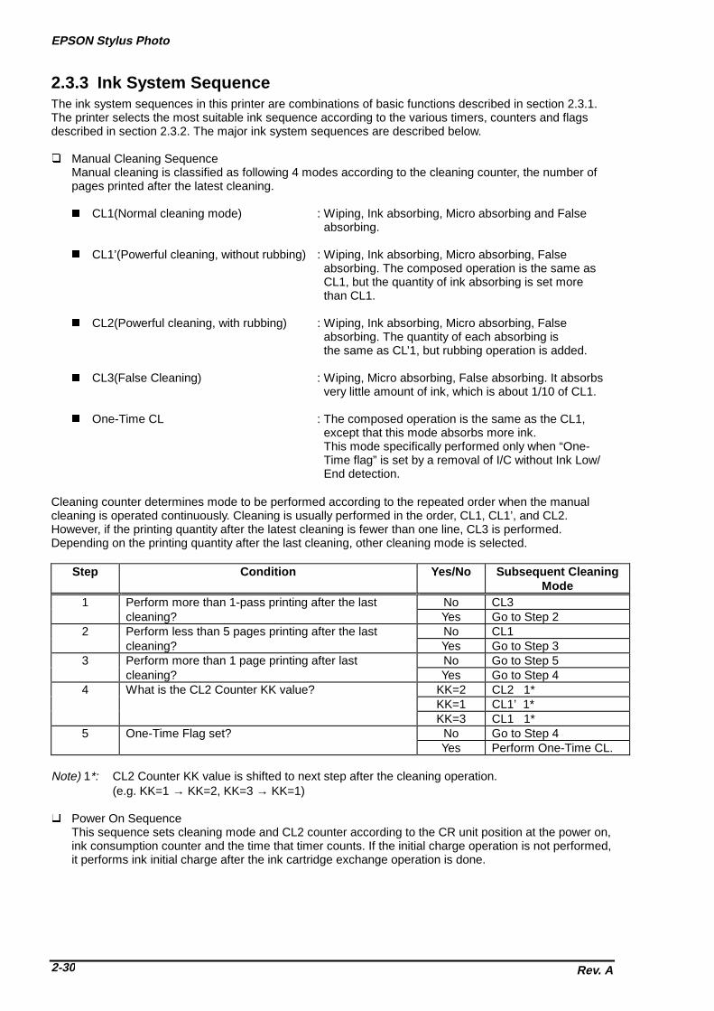
EPSON Stylus Photo
Rev. A2-30
2.3.3 Ink System SequenceThe ink system sequences in this printer are combinations of basic functions described in section 2.3.1.The printer selects the most suitable ink sequence according to the various timers, counters and flagsdescribed in section 2.3.2. The major ink system sequences are described below.
� Manual Cleaning SequenceManual cleaning is classified as following 4 modes according to the cleaning counter, the number ofpages printed after the latest cleaning.
� CL1(Normal cleaning mode) : Wiping, Ink absorbing, Micro absorbing and False absorbing.
� CL1’(Powerful cleaning, without rubbing) : Wiping, Ink absorbing, Micro absorbing, False absorbing. The composed operation is the same as CL1, but the quantity of ink absorbing is set more than CL1.
� CL2(Powerful cleaning, with rubbing) : Wiping, Ink absorbing, Micro absorbing, False absorbing. The quantity of each absorbing is the same as CL’1, but rubbing operation is added.
� CL3(False Cleaning) : Wiping, Micro absorbing, False absorbing. It absorbs very little amount of ink, which is about 1/10 of CL1.
� One-Time CL : The composed operation is the same as the CL1, except that this mode absorbs more ink. This mode specifically performed only when “One- Time flag” is set by a removal of I/C without Ink Low/ End detection.
Cleaning counter determines mode to be performed according to the repeated order when the manualcleaning is operated continuously. Cleaning is usually performed in the order, CL1, CL1’, and CL2.However, if the printing quantity after the latest cleaning is fewer than one line, CL3 is performed.Depending on the printing quantity after the last cleaning, other cleaning mode is selected.
Step Condition Yes/No Subsequent CleaningMode
1 Perform more than 1-pass printing after the last No CL3cleaning? Yes Go to Step 2
2 Perform less than 5 pages printing after the last No CL1cleaning? Yes Go to Step 3
3 Perform more than 1 page printing after last No Go to Step 5cleaning? Yes Go to Step 4
4 What is the CL2 Counter KK value? KK=2 CL2 1*KK=1 CL1’ 1*KK=3 CL1 1*
5 One-Time Flag set? No Go to Step 4Yes Perform One-Time CL.
Note) 1*: CL2 Counter KK value is shifted to next step after the cleaning operation.(e.g. KK=1 → KK=2, KK=3 → KK=1)
� Power On SequenceThis sequence sets cleaning mode and CL2 counter according to the CR unit position at the power on,ink consumption counter and the time that timer counts. If the initial charge operation is not performed,it performs ink initial charge after the ink cartridge exchange operation is done.

Chapter2 Operating Principles
Rev. A 2-31
� Cartridge Exchange SequenceThis sequence is used at the ink cartridge replacement. It is performed when the black or colorcartridge is considered as ink low at the manual cleaning operation, and panel button is pressedlonger than specified time. If the initial ink charge is not performed, this sequence performs cartridgeexchange operation and initial ink charge. After the initial ink charge operation is completed, the initialcharge flag is reset.
� Eject Paper SequenceIn order to prevent ink around the head nozzle from being viscosity, this sequence performs flushing inthe cap; 48 shots for black and 36 shots for color. Also, it performs false absorbing according to the value of ink counter RB, Ry.

Chapter 3Disassembly and Assembly
3.1 OVERVIEW ............................................................................................................3-1 3.1.1 Precautions for Disassembling the Printer.......................................................................... 3-1
3.1.2 Specification for Screws................................................................................................. ....... 3-2
3.1.3 Tools .................................................................................................................... .................... 3-2
3.1.4 Work Completion Check .................................................................................................... .... 3-3
3.2 DISASSEMBLY AND ASSEMBLY .........................................................................3-4 3.2.1 Housing Removal .......................................................................................................... ......... 3-5
3.2.2 Circuit Boards Removal................................................................................................... ...... 3-6
3.2.3 Control Panel Removal .................................................................................................... ...... 3-8
3.2.4 Waste Ink Pad Assembly Removal ....................................................................................... 3-9
3.2.5 Disassembling the Printer Mechanism............................................................................... 3-10 3.2.5.1 Printhead Removal.................................................................................................. 3-10 3.2.5.2 Pump Assembly and Cap Assembly Removal ........................................................ 3-12 3.2.5.3 CR Motor Assembly Removal ................................................................................. 3-14 3.2.5.4 PF Motor Assembly Removal.................................................................................. 3-16 3.2.5.5 ASF Assembly Removal.......................................................................................... 3-18
3.2.5.5.1 ASF Disassembly......................................................................................... 3-20 3.2.5.5.2 Pick-Up Roller Assembly Removal .............................................................. 3-21
3.2.5.6 Carriage Assembly Removal................................................................................... 3-22 3.2.5.7 PF Roller Assembly Removal.................................................................................. 3-24 3.2.5.8 PE Sensor Assembly Removal ............................................................................... 3-26 3.2.5.9 HP Sensor Assembly Removal ............................................................................... 3-27
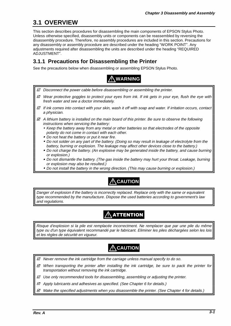
Chapter 3 Disassembly and Assembly
Rev. A 3-1
3.1 OVERVIEWThis section describes procedures for disassembling the main components of EPSON Stylus Photo.Unless otherwise specified, disassembly units or components can be reassembled by reversing thedisassembly procedure. Therefore, no assembly procedures are included in this section. Precautions forany disassembly or assembly procedure are described under the heading “WORK POINT”. Anyadjustments required after disassembling the units are described under the heading “REQUIREDADJUSTMENT”.
3.1.1 Precautions for Disassembling the PrinterSee the precautions below when disassembling or assembling EPSON Stylus Photo.
WARNING
� Disconnect the power cable before disassembling or assembling the printer.
� Wear protective goggles to protect your eyes from ink. If ink gets in your eye, flush the eye withfresh water and see a doctor immediately.
� If ink comes into contact with your skin, wash it off with soap and water. If irritation occurs, contacta physician.
� A lithium battery is installed on the main board of this printer. Be sure to observe the followinginstructions when servicing the battery:� Keep the battery away from any metal or other batteries so that electrodes of the opposite
polarity do not come in contact with each other.� Do not heat the battery or put it near fire.� Do not solder on any part of the battery. (Doing so may result in leakage of electrolyte from the
battery, burning or explosion. The leakage may affect other devices close to the battery.)� Do not charge the battery. (An explosive may be generated inside the battery, and cause burning
or explosion.)� Do not dismantle the battery. (The gas inside the battery may hurt your throat. Leakage, burning
or explosion may also be resulted.)� Do not install the battery in the wrong direction. (This may cause burning or explosion.)
CAUTION
Danger of explosion if the battery is incorrectly replaced. Replace only with the same or equivalenttype recommended by the manufacture. Dispose the used batteries according to government’s lawand regulations.
���������
Risque d’explosion si la pile est remplacée incorrectment. Ne remplacer que par une pile du mêmetype ou d’un type équivalent recommandé par le fabricant. Eliminer les piles déchargées selon les loiset les règles de sécurité en vigueur.
CAUTION
� Never remove the ink cartridge from the carriage unless manual specify to do so.
� When transporting the printer after installing the ink cartridge, be sure to pack the printer fortransportation without removing the ink cartridge.
� Use only recommended tools for disassembling, assembling or adjusting the printer.
� Apply lubricants and adhesives as specified. (See Chapter 6 for details.)
� Make the specified adjustments when you disassemble the printer. (See Chapter 4 for details.)
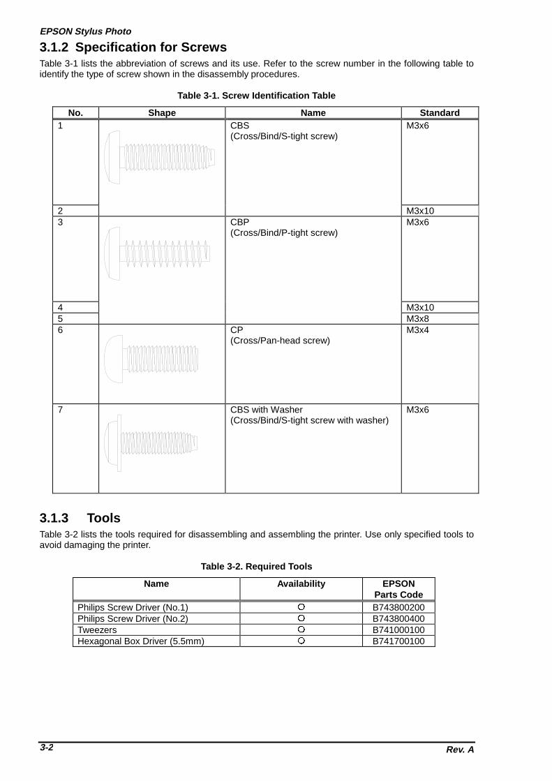
EPSON Stylus Photo
Rev. A3-2
3.1.2 Specification for ScrewsTable 3-1 lists the abbreviation of screws and its use. Refer to the screw number in the following table toidentify the type of screw shown in the disassembly procedures.
No. Shape Name Standard1 CBS
(Cross/Bind/S-tight screw)M3x6
2 M3x103 CBP
(Cross/Bind/P-tight screw)M3x6
4 M3x105 M3x86 CP
(Cross/Pan-head screw)M3x4
7 CBS with Washer(Cross/Bind/S-tight screw with washer)
M3x6
3.1.3 ToolsTable 3-2 lists the tools required for disassembling and assembling the printer. Use only specified tools toavoid damaging the printer.
Name Availability EPSONParts Code
Philips Screw Driver (No.1) � B743800200Philips Screw Driver (No.2) � B743800400Tweezers � B741000100Hexagonal Box Driver (5.5mm) � B741700100
Table 3-1. Screw Identification Table
Table 3-2. Required Tools

Chapter 3 Disassembly and Assembly
Rev. A 3-3
3.1.4 Work Completion Check
If any service is made to the printer, use the check list shown below, to confirm that all works arecompleted properly and the printer is ready to return to the user.
Category Item Check Point StatusMain Unit Self-Print Test Is the printing successful? �Checked/�Not necessary
Online Print Test Is the printing successful? �Checked/�Not necessaryPrinthead Is ink discharged normally from all
nozzle?�Checked/�Not necessary
Carriage Mechanism Does it moves smoothly? �Checked/�Not necessaryIs there any abnormal noise in itsmotion?
�Checked/�Not necessary
Is there any dirt or scratch in theCR guide shaft?
�Checked/�Not necessary
Is the CR Motor at the correcttemperature? (Not too hot)
�Checked/�Not necessary
Paper FeedingMechanism
Is paper advanced smoothly?*No paper jamming*No paper skew*No multiple feeding*No abnormal noise
�Checked/�Not necessary
Is the PF Motor at the correcttemperature? (Not too hot)
�Checked/�Not necessary
Is the paper path clear of allobstructions?
�Checked/�Not necessary
Adjustment SpecifiedAdjustment
Are all the adjustments donecorrectly?
�Checked/�Not necessary
Lubrication Specified Point Does all the lubrication made atspecified points?
�Checked/�Not necessary
Is the amount of lubricationcorrect?
�Checked/�Not necessary
System ROM Version Version (Latest): �Checked/�Not necessaryPacking Ink Cartridge Are brand-new ink cartridges
installed correctly?�Checked/�Not necessary
Protective Materials Have all relevant protectivematerials been attached to theprinter?
�Checked/�Not necessary
Other Attachment,Accessories
Have all relevant items beenincluded in the package?
�Checked/�Not necessary

EPSON Stylus Photo
Rev. A3-4
3.2 DISASSEMBLY AND ASSEMBLYThis section describes the step-by-step disassembly procedures shown in the diagram below.
HousingRemoval
Section 3.2.1
Circuit BoardsRemoval
Section 3.2.2
Control PanelRemoval
Section 3.2.3
Waste Ink Pad AssemblyRemoval
Section 3.2.4
Printer MechanismDisassembly
Seciton 3.2.5
PrintheadRemoval
Section 3.2.5.1
Pump/Cap AssemblyRemoval
Section 3.2.5.2
CR Motor AssemblyRemoval
Section 3.2.5.3
PF Motor AssemblyRemoval
Section 3.2.5.4
ASF AssemblyRemoval
Section 3.2.5.5
ASFDisassembly
Section 3.2.5.5.1
Pick-Up Roller AssemblyRemoval
Section 3.2.5.5.2
Carriage AssemblyRemoval
Section 3.2.5.6
PF Roller AssemblyRemoval
Section 3.2.5.7
PE Sensor AssemblyRemoval
Section 3.2.5.8
HP Sensor AssemblyRemoval
Section 3.2.5.9
Figure 3-1. Flow Chart of Disassembly

Chapter 3 Disassembly and Assembly
Rev. A 3-5
3.2.1 Housing RemovalSince the EPSON Stylus Photo has no lower housing as previous EPSON printers, the printer mechanismcan be taken out by only removing the upper housing. 1. Open the printer cover and set the PG adjust lever on the right-hand side to (+) position.2. Remove 4 screws (No.2) and remove the upper housing.
WORK POINT
Pull the front end of the upper housing while lifting up the upper housing to remove it.
CAUTION
Be careful not to pinch the cables with the posts of the upper housing when reinstalling it. (Especiallywith the cables from the motors and doing so causes fatal damage to the mechanism and the electriccircuitry.)
Upper Housing
Figure 3-2. Housing Removal

EPSON Stylus Photo
Rev. A3-6
3.2.2 Circuit Boards RemovalThe electric circuit boards of the printer (Main control circuit board: C209 MAIN / Power supply circuitboard: C206 PSB/PSE) are both installed on single metal chassis and attached to the printer mechanism.Therefore, first detach the metal chassis from the printer mechanism to remove the electric circuit boards.
1. Remove the upper housing (Refer to section 3.2.1)2. Remove 5 screws (No.1 / three at the back of the printer mechanism and one each at both sides
of the printer mechanism)3. Slightly pull out “SHIELD PLATE, M/B” (metal chassis) from the printer mechanism and take out
the cable holders inserted to the edge of “SHIELD PLATE, M/B”.4. Fully separate “SHIELD PLATE, M/B” from the printer mechanism and remove all cables
connected to the connectors on the main board; C209 MAIN.5. If you need further to remove each electric circuit board from “SHIELD PLATE, M/B”, remove the
screws fixing each board and remove the board.
� C209 MAIN BOARD: 10 screws (No.1 = 7 screws, No.6 = 3 screws)� C206 PSB/PSE BOARD: 4 screws (No.1)
Also disconnect the cable from the connector; CN10 (locking type) on the C209 MAIN, when youremove the C206 PSB/PSE BOARD.
Unlock the connector CN6/7 on the C209 MAIN by pulling its lock before disconnect the cables, andbe sure to lock it when reconnecting the cables.
WORK POINT
[Cable Holders]
SHIELD PLATE, M/B
Figure 3-3. SHIELD PLATE M/B Removal

Chapter 3 Disassembly and Assembly
Rev. A 3-7
REQUIRED ADJUSTMENT
Be sure to perform the following adjustments when the C209 MAIN board is replaced:1) VH Setting (Refer to Chapter 4 / Section 4.2.2.4.)2) Head Angular Adjustment (Refer to Chapter 4 / Section 4.2.2.5.)3) Bi-D Alignment Adjustment (Refer to Chapter 4 / Section 4.2.2.6.)
MAIN Board(C209 MAIN)
Power Supply Board(C206 PSB/PSE)
SHIELD PLATE, M/B
Figure 3-4. Circuit Boards Removal

EPSON Stylus Photo
Rev. A3-8
3.2.3 Control Panel Removal
1. Remove the upper housing (Refer to Section 3.2.1)2. Remove 2 screws (No.1) and remove the “PANEL, ASSEMBLY” and “HOUSING, PANEL, LEFT” from
the printer mechanism and disconnect the flat cable from the connector of the panel assembly.
By removing the control panel assembly, the stacker assembly is also detached from the printermechanism since it is held by the control panel assembly.
WORK POINT
HOUSING, PANEL, LEFT
STACKER, ASSEMBLY
SHIELD PLATE, PANEL
C209 PNL Board
PANEL, ASSEMBLY
Figure 3-5. Control Panel Removal

Chapter 3 Disassembly and Assembly
Rev. A 3-9
3.2.4 Waste Ink Pad Assembly Removal
1. Removing the upper housing (Refer to section 3.2.1)2. Removing the control panel assembly (Refer to section 3.2.3)3. Remove 1 screw (No.4) at the right-hand side of the printer mechanism, that fixing “Waste Ink Pad
Assembly”.4. Remove “SPACER, TRAY” fixing “Waste Ink Pad Assembly” at the left-hand side of the printer
mechanism and remove “Waste Ink Pad Assembly” by pulling it downward.
CAUTION
When you replace “Waste Ink Pad Assembly” to new one, be sure to perform the ink counter resetoperation. (Refer to Chapter 1 / Section 1.4.2 for details)
WORK POINT
When re-installing “Waste Ink Pad Assembly”, be sure that “Stopper, Stacker” that attached to the exitroller shaft is correctly pushed in to back of the projections of “Waste Ink Pad Assembly”.
SPACER, TRAY
Waste Ink Pad Assembly
[Projections]
Section (A)
STOPPER, STACKER
Paper Exit Roller Shaft
Front side
Push it to the back ofprojection
Figure 3-6. Waste Ink Pad Assembly Removal
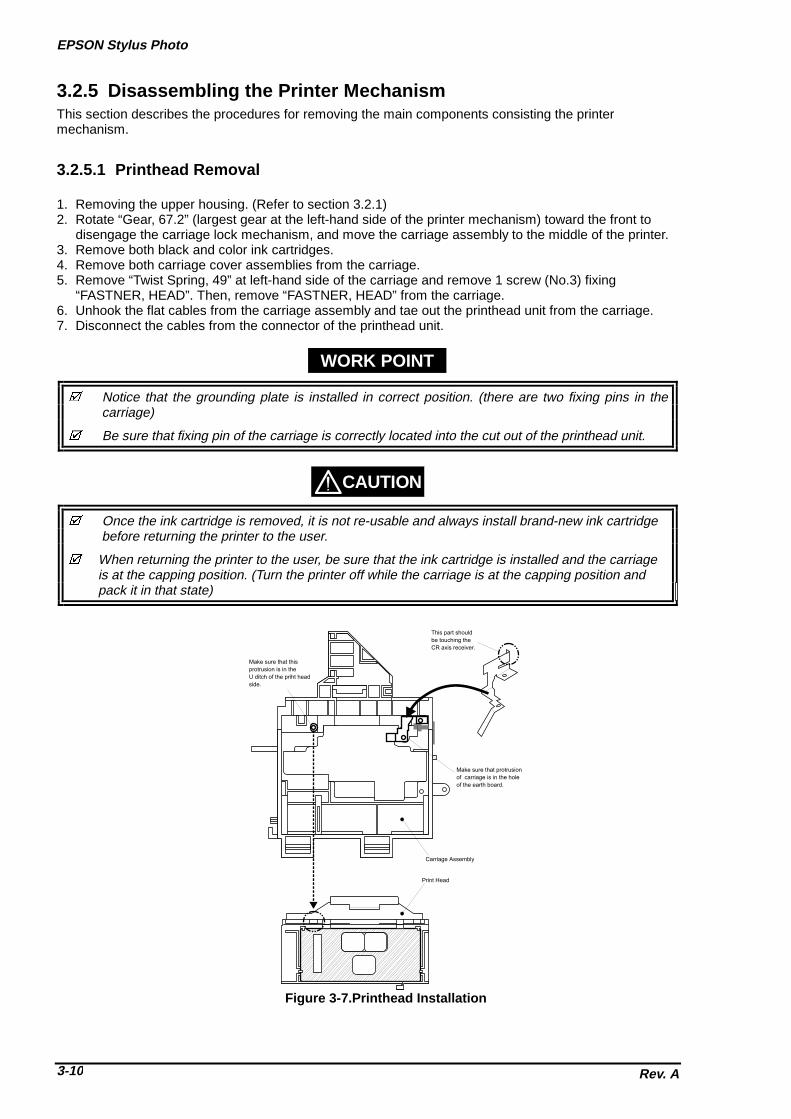
EPSON Stylus Photo
Rev. A3-10
3.2.5 Disassembling the Printer MechanismThis section describes the procedures for removing the main components consisting the printermechanism.
3.2.5.1 Printhead Removal 1. Removing the upper housing. (Refer to section 3.2.1)2. Rotate “Gear, 67.2” (largest gear at the left-hand side of the printer mechanism) toward the front to
disengage the carriage lock mechanism, and move the carriage assembly to the middle of the printer.3. Remove both black and color ink cartridges.4. Remove both carriage cover assemblies from the carriage.5. Remove “Twist Spring, 49” at left-hand side of the carriage and remove 1 screw (No.3) fixing
“FASTNER, HEAD”. Then, remove “FASTNER, HEAD” from the carriage.6. Unhook the flat cables from the carriage assembly and tae out the printhead unit from the carriage.7. Disconnect the cables from the connector of the printhead unit.
WORK POINT
� Notice that the grounding plate is installed in correct position. (there are two fixing pins in the carriage)
� Be sure that fixing pin of the carriage is correctly located into the cut out of the printhead unit.
CAUTION
� Once the ink cartridge is removed, it is not re-usable and always install brand-new ink cartridge before returning the printer to the user.
� When returning the printer to the user, be sure that the ink cartridge is installed and the carriage is at the capping position. (Turn the printer off while the carriage is at the capping position and pack it in that state)
Print Head
Carriage Assembly
Make sure that protrusion
of carriage is in the hole
of the earth board.
This part should be touching the
CR axis receiver.
Make sure that this
protrusion is in the
U ditch of the priht head
side.
Figure 3-7.Printhead Installation

Chapter 3 Disassembly and Assembly
Rev. A 3-11
� If you remove the Flat cable from the printer mechanism, make sure that the Flat cable is fixed tothe frame firmly when assembling.
REQUIRED ADJUSTMENT
When you remove or replace the printhead unit, be sure to perform the following adjustments:
1) Ink Charge Operation (Refer to Chapter 4 / Section 4.2.2.3.)2) VH Setting (Refer to Chapter 4 / Section 4.2.2.4.)3) Head Angular Adjustment (Refer to Chapter 4 / Section 4.2.2.5.)
Printhead Unit
Flat Cable
FASTNER, HEAD
TWIST SPRING, 49
Figure 3-8. Printhead Unit Removal
CAUTION

EPSON Stylus Photo
Rev. A3-12
3.2.5.2 Pump Assembly and Cap Assembly Removal
1. Removing the upper housing. (Refer to Section 3.2.1)2. Removing the control panel assembly. (Refer to section 3.2.3)3. Removing “Waste Ink Pad Assembly”. (Refer to section 3.2.4)4. Loosen 2 screws (No.1) fixing the exit frame assembly and disengage the frame from the side frames.
Then, put the printer mechanism on its back as you can see the bottom of the mechanism.5. At the right-hand of the mechanism, unhook the cap assembly by releasing one hook and take out the
cap assembly by lifting up the right end of it. (Note that the cap assembly is still connected to the pumpassembly by the ink tube.)
6. Remove 2 screws (No.5) fixing the pump assembly to the frame.7. Unhook the pump assembly by releasing one hook and slide the pump assembly to the right direction
to remove it.
� Be careful not to damage rubber part of the cap assembly. (Damaging the rubber part causesincomplete capping and the nozzle condition become unstable.)
� Be careful with the followings when you handle “CLEANER, HEAD”:•Do not handle it with bare hands and avoid attaching any oil or dust.•Make sure that the rubber side of “CLEANER, HEAD” is facing to the right.
� Be careful not to popping the components from the pump assembly when you remove it from themechanism, since there is a spring inside the pump assembly.
� Be sure that the ink tube from the cap assembly is routed to the correct position and not pinchedby the cap assembly and the frame.
� Verify that “CLEANER, HEAD” moves smoothly by rotating “GEAR, 67.2” after you re-assemblethe pump assembly. (Hold the cap assembly to the right direction while you rotating the gear forcheck)
CAUTION
WORK POINT
OK
NG
Viewed from front
(Ink tube goes behind ofthe cap assembly)
(The ink tube is on the part ofthe cap assembly)
Ink Tube Routing
Figure 3-9. Ink Tube Routing

Chapter 3 Disassembly and Assembly
Rev. A 3-13
CAP ASSEMBLY
PUMP ASSEMBLY
Loosen screw andlift up the exit frame
Unhock the cap assembly
Remove 2 screws and unhook the hooksto remove the pump assembly
Figure 3-10.Cap Assembly Removal
CLEANER, HEAD
Pump ComponentsAssembly Order
Figure 3-11.Pump Assembly Removal

EPSON Stylus Photo
Rev. A3-14
3.2.5.3 CR Motor Assembly Removal
1. Removing the upper housing. (Refer to section 3.2.1)2. Rotate “Gear, 67.2” (largest gear at the left-hand side of the printer mechanism) toward the front to
disengage the carriage lock mechanism, and move the carriage assembly to the middle of the printer.3. Push “HOLDER, PULLEY, DRIVEN” inward to loosen the timing belt and detach the timing belt from
the drive pulley of CR Motor assembly.4. Remove 2 screws (No.1) and remove “MOTOR, ASSEMBLY, CR” from the mechanism.
WORK POINT
Be sure that the projections of the motor bracket is inserted to the holes of the frame properly.
REQUIRED ADJUSTMENT
When you replace “MOTOR, ASSEMBLY, CR”, be sure to perform the following adjustment:
1) Bi-D Alignment Adjustment (Refer to Chapter 4 / Section 4.2.2.6.)
COMPRESSION SPRING, 19.6 PULLEY, ASSEMLBLY, DRIVEN
TIMING BELT
HOLDER, PULLEY, DRIVEN
Outside side frame
Inside side frame
Figure 3-12. Driven Pulley Removal

Chapter 3 Disassembly and Assembly
Rev. A 3-15
The projections of motor assembly mustlocate inside the holes
Figure 3-13. CR Motor Removal

EPSON Stylus Photo
Rev. A3-16
3.2.5.4 PF Motor Assembly Removal
1. Removing the upper housing. (Refer to section 3.2.1)2. Removing “Waste Ink Pad Assembly”. (Refer to section 3.2.4)3. By referring the figure below, remove the specified gears from the mechanism:� “GEAR, 67.2”� “COMBINATION GEAR, 8, 14.4”� “COMBINATION GEAR, 8.8, 21.6”� “GEAR, 36”
4. Remove 2 hexagonal lock nuts and remove “MOTOR, ASSEMBLY, PF”.
� When removing the PF Motor, first, slightly pulling out the PF Motor from the frame and slide the motor shaft to a larger cut out of the frame and remove it.
� Be careful with the routing direction of the cable from the PF motor.
WORK POINT
MOTOR, ASSEMBLY, PF
Hexagonal Nut
COMPRESSION SPRING, 0.9
GEAR, 67.2
Lock Ring
GEAR, 36
COMBINATION GEAR, 8.8, 21.6
COMBINATION GEAR, 8, 14.4
Figure 3-14. PF Motor Removal

Chapter 3 Disassembly and Assembly
Rev. A 3-17
MOTOR, ASSEMBLY, PF(behind the frame)
Cable Direction
Put the motor shaft once in a larger holdthen slide it to a smaller hole
Figure 3-15. PF Motor and Frame

EPSON Stylus Photo
Rev. A3-18
3.2.5.5 ASF Assembly Removal
1. Removing the upper housing. (Refer to section 3.2.1)2. Remove the locking pin from center of “GEAR, 34” and remove “GEAR, 34” from the shaft.3. Unhook the cables from the cable hook of the ASF and the printer mechanism.4. Remove 2 screws (Refer to the figures) fixing the ASF and remove the ASF from the mechanism by
detaching the projection of ASF (at left) from the hole of the mechanism.
WORK POINT
� Make sure that the ASF is firmly attached to the mechanism.
� Use proper type of screw at specified position (viewed from the back of the mechanism):Right: “SHAFT, FIXING, CR”Left: Screw - No.7 (CBS with washer)
CAUTION
When re-installing the ASF, be sure that no cables (except the flat cable to the printhead) are pinchedbetween the ASF and the frame.
Especially, if the cables from CR/PF Motor is pinched, there is a danger of short-circuit with the frameand possibly causes hazardous problem like over-heating, burning of components.
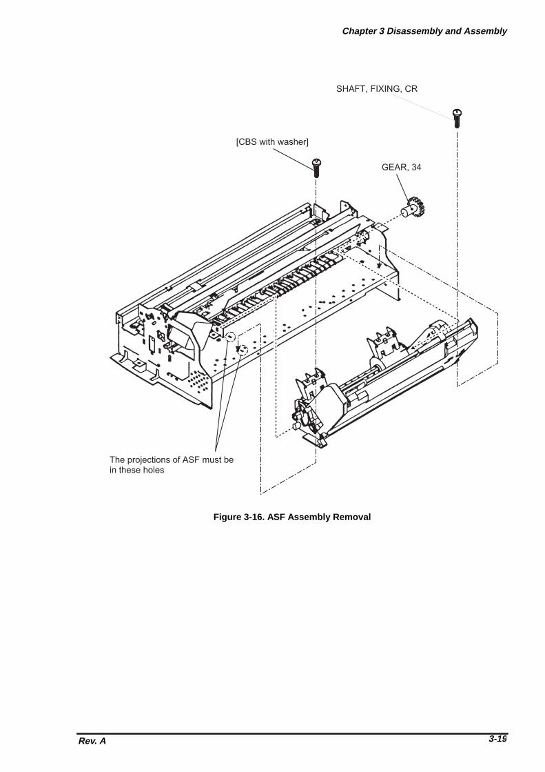
Chapter 3 Disassembly and Assembly
Rev. A 3-19
SHAFT, FIXING, CR
[CBS with washer]
The projections of ASF must bein these holes
GEAR, 34
Figure 3-16. ASF Assembly Removal

EPSON Stylus Photo
Rev. A3-20
3.2.5.5.1 ASF Disassembly
1. Removing the ASF. (Refer to section 3.2.5.5)2. Remove “TWIST SPRING, 41.2” by unhooking one end from the ASF frame and remove “LEVER,
BRAKE”.3. Remove “BUSH, FIXING, SHAFT” from the right end of “SHAFT, ROLLER, LD” and remove “LEVER,
HOPPER, RELEASE”.4. Move the left paper pick-up assembly to the middle of the ASF and remove “BUSH” from the shaft.5. Push out “SHAFT, ROLLER, LD” to the left and remove “BUSH, FIXING, SHAFT, LEFT” from the left-
end of the shaft by unhook it.6. Unhook the top of “HOPPER, ASSEMBLY” from the both sides of “FRAME, ASF”.7. Push out “SHAFT, ROLLER, LD” to the right while pulling up “PICKUP, ROLLER ASSEMBLY, RIGHT”
slightly. Then, detach the left end of “SHAFT, ROLLER, LD” from “FRAME, ASF”.8. Holds “HOPPER, ASSEMBLY” and remove the right cam part of “HOPPER, ASSEMBLY” through the
hole at the right side of “FRAME, ASF”. To this point, the ASF assembly is disassembled and both left and right “PICKUP, ROLLER ASSEMBLY”
and “HOPPER, ASSEMBLY” are separated.
WORK POINT
� When removing “HOPPER, ASSEMBLY”, be careful that the grease that applied to the cam partof it, not to attach to the other part of the ASF. If so, wipe it off completely.
� Be careful of the direction when you install the “LEVER, HOPPER, RELEASE”.
� Make sure that bushes at the both ends of the shaft are firmly attached.
HOPPER, ASSEMBLY
LEVER, BRAKE
TWIST SPRING, 41.2
BUSH, FIXING, SHAFT, LEFT
FRAME, ASF
LEVER, HOPPER, RELEASE
BUSH, FIXING, SHAFTSHAFT, ROLLER, LD
BUSH
CAM part
Figure 3-17. ASF Disassembly

Chapter 3 Disassembly and Assembly
Rev. A 3-21
3.2.5.5.2 Pick-Up Roller Assembly Removal
1. Disassemble the ASF and separate “PICKUP, ROLLER ASSEMBLY” and “HOPPER, ASSEMBLY”.(Refer to section 3.2.5.5.1)
2. Remove “COMPRESSION SPRING, 1.66” from the back of “HOPPER, ASSEMBLY”.3. Pull out the right cam part of “HOPPER, ASSEMBLY” though the hole of right frame of “PICKUP,
ROLLER ASSEMBLY, RIGHT”.
<To this point, “HOPPER, ASSEMBLY” and “PICKUP, ROLLER ASSEMBLY” is separated>4. Unhook “ROLLER ASSEMBLY, LD” from the assembly frame and remove “COVER, ROLLER, LD” by
unhooking it from the assembly frame. Then, remove “ROLLER ASSEMBLY, LD”.
WORK POINT
� When you re-assemble, be sure that “ROLLER ASSEMBLY, LD” is hooked to assembly framefirmly.
� Before re-assemble the unit, make sure that “COMPRESSION SPRING, 1.66” is set on theassembly frame and hooked to the hooks as shown in the figure. This helps you easierassembly. After assemble the unit, do not forget to unhook the springs by rotating the springfrom the holes located at the back of the ASF assembly.
COVER, ROLLER, LD (L/R)+
HOLDER, SHEET, PF
COMPRESSION SPRING, 1.66
ROLLER, ASSEMBLY, LD (L/R)
ASSEMBLY FRAME
Set the spring and hook itto the assembly frame asillustrated, before re-assembly
Figure 3-18. Pick-Up Roller Removal

EPSON Stylus Photo
Rev. A3-22
3.2.5.6 Carriage Assembly Removal
1. Removing the upper housing. (Refer to section 3.2.1)2. Push “HOLDER, PULLEY, DRIVEN” inward to loosen the timing belt and detach the timing belt from
the drive pulley of CR Motor assembly.3. Take out “COMPRESSION SPRING, 19.6” from “HOLDER, PULLEY, DRIVEN”.4. Remove “PULLEY, ASSEMBLY, DRIVEN” and the timing belt together from “HOLDER, PULLEY,
DRIVEN” and remove “HOLDER, PULLEY, DRIVEN” from the mechanism.5. Unhook “LEVER, PG” and remove it.6. Unhook “LEVER, PG, SUB” and remove “LEVER, PG, SUB” and a spring washer from the end of
“SHAFT, CR, GUIDE”.7. Remove 1 screw (No.7) and rotating “BUSH, PARALLEL ADJUST, RIGHT” to match it with the cut out
of the frame. Then, take out “BUSH, PARALLEL, ADJUST, RIGHT”.8. Remove “CARRIAGE, ASSEMBLY” together with “SHAFT, CR, GUIDE”.
WORK POINT
� It is good idea to mark the current position of “BUSH, PARALLEL ADJUST, RIGHT” beforeremoval. This enables you to omit the paper gap adjustment after the assembly.
� Be careful with the direction of spring washer at the assembly. (A convex side must face thebush)
REQUIRED ADJUSTMENT
When you remove or replace the carriage assembly, be sure to perform the following adjustments:
1) Paper Gap Adjustment (Refer to Chapter 4 / Section 4.2.1.)2) Head Angular Adjustment (Refer to Chapter 4 / Section 4.2.2.5.)3) Bi-D Alignment Adjustment (Refer to Chapter 4 / Section 4.2.2.6.)
BUSH, PARALLEL ADJUST, RIGHT
Side frame ofprinter mechanism
BUSH, PARALLEL ADJUST, RIGHT
Cut out of side frame
Figure 3-19. BUSH PARALLEL ADJUST Removal

Chapter 3 Disassembly and Assembly
Rev. A 3-23
Carriage Assembly
BUSH, PARALLEL ADJUST, LEFT
BUSH, PARALLEL ADJUST, RIGHT
LEVER, PG, SUB
Spring Washer(Convex side must be facing the bush)
SHAFT, CR, GUIDE
Figure 3-20. Carriage Assembly Removal

EPSON Stylus Photo
Rev. A3-24
3.2.5.7 PF Roller Assembly Removal
1. Removing the upper housing. (Refer to section 3.2.1)2. Removing the carriage assembly (Refer to section 3.2.5.6)3. Remove 2 screws (No.1) at the top of mechanism and remove “GUIDE PLATE, CABLE”.4. From the back of the mechanism, unhook the springs from the frame and remove “PAPER GUIDE,
ASSEMBLY, UPPER” (total 6 pieces).5. Unhook “PAPER GUIDE, FRONT;B” and remove it.6. Unhook the both shaft holders of “ROLLER, ASSEMBLY, PAPER EXIT” and remove it.7. Unhook the left shaft holder of “ROLLER, ASSEMBLY, PF” and rotate it as to match with the cut out of
the frame.8. Slide “ROLLER, ASSEMBLY, PF” to the left and pulling it out.
WORK POINT
� When reinstalling “PAPER GUIDE, ASSEMBLY, UPPER” at right-most position (viewed from thefront), be careful with the detection lever of the PE sensor.
� Be careful not to damage the hook of “PAPER GUIDE, FRONT;B” during disassembly andassembly.
� Be careful not to damage the black coated part of “ROLLER, ASSEMBLY, PF” duringdisassembly and assembly.
� Be careful not to damage the gears.
PAPER GUIDE, LEFT
(6 pieces)
SHAFT, PAPER GUIDE, UPPER
TWIST SPRING, 117.6
GUIDE PLATE, CABLE
PAPER GUIDE, ASSEMBLY, UPPER
Figure 3-21. PAPER GUIDE ASSEMBLY Removal

Chapter 3 Disassembly and Assembly
Rev. A 3-25
PAPER GUIDE, LEFT
(6 pieces)
SHAFT, PAPER GUIDE, UPPER
TWIST SPRING, 117.6
GUIDE PLATE, CABLE
PAPER GUIDE, ASSEMBLY, UPPER
Figure 3-22. ROLLER, ASSEMBLY, PAPER EXIT Removal
PAPER GUIDE, FRONT;B
ROLLER, ASSEMBLY, PAPER EXIT
Figure 3-23. ROLLER, ASSEMBLY, PF Removal

EPSON Stylus Photo
Rev. A3-26
3.2.5.8 PE Sensor Assembly Removal
1. Removing the upper housing. (Refer to section 3.2.1)2. From the front side of the mechanism, unhook two hooks fixing “SENSOR, ASSEMBLY, PE” to the
mechanism. Then, slide it to upward to remove it. After removal, disassemble the assembly ifnecessary.
WORK POINT
When re-install the assembly, be sure that the sensor lever is correctly inserted into a hole of “PAPERGUIDE, ASSEMBLY”, UPPER”.
� Be careful not to damage the cable when inserting or pulling out it from the PE sensor board.
� Make sure the sensor lever moves smoothly when installing it.
LEVER, PEBOARD ASSY., PE
HOLDER, PE
To frame
Release these hooks toremove the PE Sensor Assembly
From the back side ofthe mechanism
Figure 3-24.PE Sensor Assembly Removal
CAUTION

Chapter 3 Disassembly and Assembly
Rev. A 3-27
3.2.5.9 HP Sensor Assembly Removal
1. Removing the upper housing. (Refer to section 3.2.1)2. Detach the cable from the sensor and remove it by unhook it from the frame.
� Make sure that the sensor itself is attached firmly to the frame when installing the HP sensoragain.
� Be careful not to damage the sensor board when installing or pulling out the cable from the HPsensor.
SENSOR, HP
CR MOTOR
Figure 3-25. HP Sensor Removal
CAUTION

Chapter 4Adjustment
4.1 OVERVIEW ............................................................................................................4-1 4.1.1 Required Adjustments ..................................................................................................... ...... 4-1
4.1.2 Tools Required for Adjustment ............................................................................................ . 4-1
4.2 Adjustments ..........................................................................................................4-2 4.2.1 Paper Gap Adjustment ..................................................................................................... ...... 4-2
4.2.2 Adjustment using Adjustment Program............................................................................... 4-4 4.2.2.1 Overview of Adjustment Program ............................................................................. 4-4 4.2.2.2 Preparation for Adjustment........................................................................................ 4-5 4.2.2.3 Ink Charge Operation ................................................................................................ 4-6 4.2.2.4 VH Setting ................................................................................................................. 4-6 4.2.2.5 Head Angular Adjustment ......................................................................................... 4-8 4.2.2.6 Bi-D Alignment Adjustment ..................................................................................... 4-10

Chapter 4 Adjustment
Rev. A 4-1
4.1 OVERVIEWThis section describes the procedure for adjustments required when the printer is disassembled andassembled for repair.
4.1.1 Required AdjustmentsTable 4-1 lists all the adjustments required with this printer. If any service listed in this table is carried out,all adjustments corresponding to that service should be performed to ensure proper operation of theprinter.
Performance Order 1 2 3 4 5Service Performed Paper-Gap
AdjustmentInk
ChargeVH
SettingHead
AngularAdjustment
Bi-DAdjustment
Replacingthe printer mechanism
NA � � NA �
Replacingthe C209 MAIN board
NA � � � �
Replacingthe printhead unit
NA � � � NA
Replacingthe CR Motor
NA NA NA NA �
Replacing or disassemblingthe carriage assembly
� NA NA � �
Replacing or disassemblingthe PF Roller assembly
� NA NA NA NA
Note) “�”: Required adjustment“NA”: Not applicable
4.1.2 Tools Required for AdjustmentTable 4-2 lists all the tools required to make the specified adjustments.
No. Name Adjustment Notes1 Thickness Gauge Paper-Gap Adjustment � Thickness: 1.04mm
� EPSON Code: B7767022012 Adjustment Program � Ink Charge
� VH Setting� Head Angular� Bi-D Alignment
� Program Name: K00A10VE.BAS
� Do not use rusty or deformed thickness gauge for adjustment.
� Wipe off any dirt or dust from the thickness gauge before using.
Table 4-1. Required Adjustments
Table 4-2. Required Tools
CAUTION

EPSON Stylus Photo
Rev. A4-2
4.2 AdjustmentsThis section describes the detail procedure of each adjustment.
4.2.1 Paper Gap AdjustmentThe paper gap is a distance between nozzle surface of the printhead unit and a paper surface and isadjusted to specified gap at the assembly. Therefore, if the carriage assembly is removed from the printermechanism for any reason, this adjustment should be made to fix the gap.
� Do not scratch the surface of “PAPER GUIDE, FRONT;B” and “ROLLER, ASSEMBLY, PF”.
� Be careful not to damage or make dirty the nozzle surface of the printhead unit.
[Paper gap - Right-hand side Adjustment]1. Attach both “BUSH, PARALLEL ADJUST” (L/R) to the side frame and align the position mark on top
edge of it to a notch on the edge of the side frame.2. Set “LEVER, PG” to front side (Position “0”).3. Move the carriage assembly to the middle, and put the thickness gauge at the position specified in the
figure.4. Move the carriage assembly over the thickness gauge.
� The thickness gauge must be placed on a flat surface of the ribs of “PAPER GUIDE, FRONT;B”.
� During adjustment, always pull the timing belt to move the carriage assembly.
5. Shift the position of “BUSH, PARALLEL ADJUST, RIGHT” to backward (Gap: Narrower) until when the
thickness gauge starts sliding together with the carriage assembly when you move it to right and left forabout 20mm.
6. At the point of above step, shift the position of “BUSH, PARALLEL ADJUST, RIGHT” for one notch toforward (Gap: Wider).
7. Then, confirm that the thickness gauge do not slide when you move the carriage assembly, with either“LEVER, PG” is at position “0” or “+”.
[Paper gap - Left-hand side Adjustment]8. Repeat the above step 2 to 7 with “BUSH, PARALLEL ADJUST, LEFT”.
[Gap Confirmation]9. Repeat the step 3 to 4 again.10. Confirm that the thickness gauge do not slide when you move the carriage assembly to right and left
for above 20mm.11. Shift the position of “BUSH, PARALLEL ADJUST, RIGHT” for one notch to backward (Gap: Narrower)
and confirm that the thickness gauge is sliding by moving the carriage assembly. If not, return to step 1and repeat adjustment again.
12. If the gap is correct, shift “BUSH, PARALLEL ADJUST, RIGHT” for one notch to forward (Gap: Wider).
[Fixing “BUSH, PARALLEL ADJUST”]13. Fix both bushes with 2 screws (1 each : No.1).
When the paper gap adjustment complete, confirm that the overlap of printhead nose and “CLEANER,HEAD”.
1. Move the carriage assembly next to “CLEANER, HEAD”.2. Confirm that the overlap of printhead nose and top edge of “CLEANER, HEAD” is more than 0.5mm.
CAUTION
WORK POINT
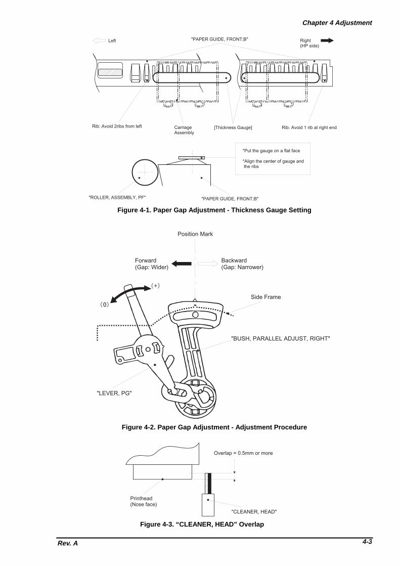
Chapter 4 Adjustment
Rev. A 4-3
Left "PAPER GUIDE, FRONT;B" Right(HP side)
Rib: Avoid 2ribs from left CarriageAssembly
[Thickness Gauge] Rib: Avoid 1 rib at right end
"ROLLER, ASSEMBLY, PF" "PAPER GUIDE, FRONT;B"
*Put the gauge on a flat face
*Align the center of gauge and the ribs
Figure 4-1. Paper Gap Adjustment - Thickness Gauge Setting
Position Mark
Forward(Gap: Wider)
Backward(Gap: Narrower)
Side Frame
"BUSH, PARALLEL ADJUST, RIGHT"
"LEVER, PG"
Figure 4-2. Paper Gap Adjustment - Adjustment Procedure
Printhead(Nose face)
"CLEANER, HEAD"
Overlap = 0.5mm or more
Figure 4-3. “CLEANER, HEAD” Overlap

EPSON Stylus Photo
Rev. A4-4
4.2.2 Adjustment using Adjustment ProgramSince the characteristic of printer mechanism and its components are varying, every printer mechanismare checked and it’s own characteristic information is stored in EEPROM of the main control board as acompensation parameter for the mechanism control. Therefore, if the combination of printer mechanismand the main control board is changed, the printer should be adjusted using the adjustment program inorder to maintain optimum performance of the printer.
4.2.2.1 Overview of Adjustment ProgramThis adjustment program(K00A10VE.BAS) is developed specifically for this printer and the basic operationwith this adjustment program is illustrated in figure below.
Main Menu(Item Selection)
Initial Ink Charge
Performance of Initial ink charge process
Head VH voltage ID writing.
Head Angle Adjustment Bi-D Adjustment
*Pattern printing*Confirmation/ Mechanism Adjustment
*Pattern printing*Confirmation/ Input of correct values
Input of appointedVH voltge ID
Figure 4-4. Adjustment Program Flow

Chapter 4 Adjustment
Rev. A 4-5
4.2.2.2 Preparation for Adjustment
Before you start adjustment, have the following items ready for adjustment.
� PC (MS-DOS Machine)� I/F cable (Parallel)� Brand new ink cartridges (Black and Color)� Photo quality ink jet paper (#S041061/2)� Printer that is necessary to adjust (At least, the printer mechanism, electrical
circuits, boards and panel should be connected.)
� Make sure to use the new ink cartridge, which is not used and also not opened before.
� Use the special ink-jet paper in order to check the adjustment result accurately.
1. Connect the PC to the printer and turn the PC and the printer on. Then, unpack a brand-new inkcartridges and install them on to the printer.
2. Load “GWBASIC.EXE” and execute the adjustment program “K00A10VE”.3. At the menu [SCREEN-1], input “2” to select “Cartridge” and press ENTER key.4. Then, at the menu [SCREEN-2], input the number corresponding to your market and press ENTER
key.
[SCREEN-1] ***** TOOL ***** PM-700C/STYLUS COLOR PHOTO K00A10Ve
1. Jig2. Cartridge
Input ITEM No. : ?_
[SCREEN-2] ***** CUSTOMER ***** PM-700C/ STYLUS COLOR PHOTO K00A10Ve
1. 000: (WORLD)2. 100: (JAPAN)3. 000: (KOREA)4. 000: (RUSSIA)
Input ITEM No. :?__
[SCREEN-3] <MAIN MENU for Production> STYLUS COLOR PHOTO K00A10Ve
1: VH Setting2: Ink Charge3: Angular Adjust Printing XX-XX-XXXX XX:XX:XX
K: Angular Adjust Setting 4: Bi-d Adjust CUSTOMER:WORLD
P: Print Inspection (GOS) Jig No. :CTL: Print Inspection (S/F) M/C No. :M: Print Inspection (Post-card)
HEAD VH :CL. Cleaning:9. INK Discharge
E. END / Go to SETTING MENU
Input ITEM No. :?_
CAUTION

EPSON Stylus Photo
Rev. A4-6
4.2.2.3 Ink Charge OperationIf either of the following service is made, internal ink paths of the printhead unit is completely empty.Therefore, a brand-new ink cartridge must be installed and all ink paths must be charged with fresh ink byperforming the following operation to ensure proper printing operation.
� Replacing the printer mechanism� Replacing the printhead unit
� Since this operation consumes large amount of ink, do not perform it unnecessarily:*Black: Approx. 8.8% of the ink charged in the cartridge*Color: Approx. 16.2% of the ink charged in the cartridge (CMYcm total)
� The ink charge operation takes long time to complete. Do not turn off the printer until it stopscompletely.(The POWER indicator blinks during the operation.)
1. Start “Preparation for Adjustment” and complete 1 to 4 procedures. (Refer to section 4.2.2.2)2. At the main menu [SCREEN-3], input “2” to select “Ink Charge” and press ENTER key. Then, the
printer starts the ink charge operation.
4.2.2.4 VH SettingThe piezo-electric element used in each printhead unit has unique electrical characteristic and theelectrical characteristic of each printhead is measured at the production and each printhead unit is givenwith the ID code. Therefore, this ID code is need to be stored in EEPROM on the main board when thefollowing service is made and the printer read this information to compensate the difference ofcharacteristic for printing control and an amount of injected ink is maintained at the specified level.
� Replacing the printhead unit� Replacing the printer mechanism (the after-service unit comes with the printhead unit installed)
*Refer to the next page for [SCREEN -1] to [SCREEN-3].1. When replacing the part mentioned above, take a note of the ID code indicated on the unit as below. � Printhead Unit: Stamped at the side of the unit � Printer mechanism: Indicated on a label attached to the packing box for the after-service unit. 2. Re-assemble the printer.3. Start “Preparation for Adjustment” and complete 1 to 4 procedures.(Refer to section 4.2.2.2)4. At the main menu [SCREEN-1], Input “1” to select “VH Setting” and press ENTER key.5. At the next menu screen[SCREEN-2], input “0” as “M/C No.” and press ENTER key.6. Then next menu [SCREEN-3] appears on the screen, and input the ID code which you noted at the
beginning of this procedure.
� VH ID Code format: *1st/2nd digits (from left) =Normal dot VH ID *3rd digit =Drive frequency ID
*4th/5th digits =Micro dot VH ID 7. After inputting the ID code, the program returns to the main menu and you can continue to another
adjustments.
� Timing to write the specified value to EEPROM: Upon pressing ENTER key after ID code input.
CAUTION
WORK POINT

Chapter 4 Adjustment
Rev. A 4-7
*[SCREEN-1] to [SCREEN-3] for VH Setting.
[SCREEN-1] < MAIN MENU for Production > STYLUS COLOR PHOTO K00A10Ve
1. VH Setting2. Ink Charge3. Angular Adjust-Printing XX-XX-XXXX XX:XX:XXK. Angular Adjust-Setting4. Bi-d Adjust CUSTOMER:WORLD P. Printing Inspection (GOS) JIG No. :CTL. Printing Inspection (S/F) M/C No. :M. Printing Inspection (Post-card)
HEAD VH :CL. Cleaning9. INK Discharge
E. Go to SETTING MENU
Input ITEM No.: ?_
[SCREEN-2] M/C No. ?_
[SCREEN-3]
<<<< HEAD VH WRITE >>>>
Head VH ( 5 digit ID (ex.18109 or 18A0 ):
-------------------VD VALUE-------------------M/C No. :0HEAD VH :
M/C No. ? 0
Viewed from front
Head VH ID
Figure 4-5.Head VH ID Indication

EPSON Stylus Photo
Rev. A4-8
4.2.2.5 Head Angular AdjustmentThe head angular means the angle at which the printhead unit installed on the carriage assembly againstthe carriage movement direction and the printhead must be parallel with the carriage movement directionso that the lines printed with each nozzle are evenly positioned. Therefore, this adjustment should bemade when the following service is made:
� Replacing or removing the printhead unit
The head angular actually set by the adjust lever installed on the carriage assembly and the program printthe check pattern to see the level of head angular.
*Refer to next page for [SCREEN-1] to [SCREEN-2].1. Before performing this adjustment, be sure to perform “VH Setting” (Refer to section 4.2.2.4)2. At the main menu [SCREEN-1], input “3” to select “Angular Adjust Printing” and press ENTER key.3. Check to see if the lines printed in MAGENTA color is positioned in the middle of two BLACK lines with
the check pattern printed by the program. If the position of MAGENTA lines are incorrect, input “K” toselect “Angular Adjust Setting” at the main menu and the carriage assembly moves to the middle of theprinter. Then, loosen a screw (No.3) fixing “FASTNER, HEAD” a little bit and shift the position ofangular adjust level located at the right bottom of the carriage assembly to either forward (moveMAGENTA line to down) or backward (move MAGENTA line to up).
4. After adjusting the position of angular adjust lever, input “Y” and press ENTER key and the carriageassembly returns to the home position.
5. Input “3” to print the check pattern again. If the level is still not correct, repeat the step 3 and 4.6. If the level is correct, input “K” again and tighten a screw to fix “FASTNER, HEAD”. Then, at the menu
[SCREEN-2], input “Y” and press ENTER key to complete the adjustment.
BLACK line MAGENTA line
Printed pattern
Printed pattern
Angular Adjust Lever
(Right bottom of the Carriage Assembly)
Shift the lever to:Forward
Shift the lever to:Backward
Figure 4-6. Head Angular Adjustment

Chapter 4 Adjustment
Rev. A 4-9
*[SCREEN-1] to [SCREEN-2] for Head Angular Adjustment.
[SCREEN-1] < MAIN MENU for Production > STYLUS COLOR PHOTO K00A10Ve
1. VH Setting2. Ink Charge3. Angular Adjust Printing XX-XX-XXXX XX:XX:XXK. Angular Adjust Setting4. Bi-d Adjust CUSTOMER:WORLD
P. Printing Inspection (GOS) JIG No. :CTL. Printing Inspection (S/F) M/C No. :M. Printing Inspection (Post-card)
HEAD VH : CL.Cleaning
9. INK Discharge
E. Go to SETTING MENU
Input ITEM No. : ?__
[SCREEN-2] Input ITEM No. : ? kAngular Adjustment Finish (Yes):?_

EPSON Stylus Photo
Rev. A4-10
4.2.2.6 Bi-D Alignment AdjustmentThis adjustment defines the carriage drive control parameters to compensate the variation in mechanismcomponents characteristic so that the print position become even in bi-directional printing. Thisadjustment is required when one of the following service is made:
� Replacing the printer mechanism� Replacing the main board (C209 MAIN)� Replacing the CR Motor assembly� Replacing the carriage assembly
The values defined with this adjustment are stored in EEPROM on the main board.
*Refer to next page for [SCREEN-1] to [SCREEN-3].1. If the printer mechanism is replaced, the ink charge operation and the VH Setting operation should
be performed prior to this adjustment. (Refer to section 4.2.2.3 and 4.2.2.4)2. Go to the main menu [SCREEN-1].3. Input “4” to select “Bi-d Adjust” and press ENTER key.4. The program prints the check pattern (one with the compensation value=“0” and another two patterns
each printed with the value “-2” and “+2”). Select the number of the pattern with which the printed linesare most properly aligned, and input the number and press ENTER key at the menu [SCREEN-2].Then, the program print the sample pattern with the compensation value you have selected.
5. If all patterns printed by the program are completely mis-aligned, confirm the inclination ofmisalignment with the pattern printed with the value “0” by checking the relative position of the EVENline to the ODD line:
� If EVEN line is shifted to RIGHT = Requires (−) value� If EVEN line is shifted to LEFT = Requires (+) value
Then, once input “Y” and press ENTER key to return to the main menu, and input “E” to select “Go toSETTING MENU” and press ENTER key. At the setting menu screen [SCREEN-3], input “6” to select“BI-D Center” and input the approximation number that corresponding to the inclination ofmisalignment you have confirmed previously. After changing the reference value for the Bi-D alignmentcheck printing, input “1” to select “(Production)” and back to the main menu and continue for the Bi-Dalignment adjustment from step 4.
� Timing to write the specified value to EEPROM: Upon pressing ENTER key after input “Y”.
WORK POINT
[Printed pattern]
Input (-) value
Input (+) value
Figure 4-7.Bi-D Alignment

Chapter 4 Adjustment
Rev. A 4-11
*[SCREEN-1] to [SCREEN-3] for Bi-D Alignment Adjustment.
[SCREEN-1] < MAIN MENU for Production > STYLUS COLOR PHOTO K00A10Ve
1. VH Setting2. Ink Charge3. Angular Adjust Printing XX-XX-XXXX XX:XX:XXK. Angular Adjust Setting4. Bi-d Adjust CUSTOMER:WORLD
P. Printing Inspection (GOS) JIG No. :CTL. Printing Inspection (S/F) M/C No. :M. Printing Inspection (Envelope)
HEAD VH : CL. Cleaning
9. INK Discharge
E. Go to SETTING MENU
Input ITEM No. : ?_
[SCREEN-2]
<< Definable Range (-30=< x <=30). >>
Input Adjust Value (If OK, input Y) :? _
[SCREEN-3] ***** SETTING MENU ***** K00A10Ve
1: (Production)/Adjustment2:
3: DATE/TIME [XX-XX-XXXX] [XX:XX:XX] 4: TOOL [CT] JI=JIG CT=Cartridge WAIT=80s 5: CUSTOMER [WORLD]
6: BI-D Center [ 0 ]7: Print Position [60]
Q: QUIT
Input ITEM No.: ?

Chapter 5Troubleshooting
5.1 Troubleshooting....................................................................................................5-1
5.2 Unit Level Troubleshooting .................................................................................5-3 5.2.1 Printer does not operate at power on................................................................................... 5- 4
5.2.2 Error is detected ........................................................................................................ ............. 5-5
5.2.3 Failure occurs during printing ........................................................................................... ... 5-6
5.2.4 Printer does not feed the paper correctly ............................................................................ 5-7
5.2.5 Control panel operation is abnormal.................................................................................... 5- 8
5.3 Unit Repair C206 PSB/PSE Board .......................................................................5-9 5.3.1 Unit Repair - C209 MAIN Board ........................................................................................... 5 -11
5.4 Repair of the Printer Mechanism.......................................................................5-13

EPSON Stylus Photo
Rev. A 5-1
5.1 TroubleshootingThe printer may exhibit different symptoms for the same problem, which makes troubleshooting moredifficult. This section, however, provides simple and effective ways to facilitate troubleshooting.The following flowchart illustrates the main steps of the troubleshooting process.
Motor Name Location Check Point No.* Meter Reading
CR MotorAssembly
CN6(C209 MAIN) 1 & 3pin or,2 & 4pin
7.8 Ohms ±10%(25 °C)
PF(Pump) MotorAssembly
CN7(C209 MAIN) 1 & 3pin or,2 & 4pin
7.8 Ohms ±10%(25 °C)
Note*) Set the Multi-meter for measuring resistance range.Make sure the power is off and remove the motor connectors from the main board.
Sensor Name Check Point Signal Level Sensor StatusPaper end sensor CN4 / 1-pin, H (5V) No paper
L (GND) Paper inCarriage homeposition sensor
CN5 / 1-pin, H (5V) Home position
(HP sensor) L (GND) Out of home positionASF phase Sensor CN11 / 1-pin, H (5V) Friction(paper feeding) position
L (GND) Release(waiting) positionBlack cartridge sensor
CN8 / 1-pin, H (5V) Black ink cartridge out
L (GND) Black ink cartridge existsColor cartridge sensor CN8 / 2-pin, H (5V) Color ink cartridge out
L (GND) Color ink cartridge existsThermistor CN8 / 3-pin, Resistance value It changes according to the
peripheral temperature.(10KOhms ±1% at 25°C)
START
END
Unit Level Troubleshooting
Unit Repair(C206 PSB/PSE)
Unit Repair(C209 Main)
Unit RepairPrinter Mechanism
Disassembly and Adjustment
Figure 5-1. Troubleshooting Process Flowchart
Table 5-1. Motor Resistance and Measurement Procedure
Table 5-2. Sensor Check

Chapter 5 Troubleshooting
Rev.A5-2
Error statusIndicators
RecoveryPower Ink Out
(Black)Ink Out(Color)
Paper Out
Paper Out --- --- --- On Load paper then pressload/eject button.
Paper jam condition --- Off Off Blink Eliminate a paper then pressload/eject button.
No Ink cartridge or Inkend(black)
--- On --- --- Install a new black ink cartridgeaccording to ink cartridgeexchange operation.
No Ink cartridge or Inkend(color)
--- --- On --- Install a new color ink cartridgeaccording to ink cartridgeexchange operation.
Ink low (Black) --- Blink --- --- ---Ink low (Color) --- --- Blink --- ---Maintenance error Blink Blink Blink Blink Change the waste ink absorber
and reset the protect counter.Fatal error Blink On On Blink Turn off the printer and turn it
on again. If the printer can notrecover, repair the suitable part.
Table 5-3. Printer Condition and Panel Status

EPSON Stylus Photo
Rev. A 5-3
5.2 Unit Level TroubleshootingWhen a problem occurs, you can identify the defective unit according to the symptoms exhibited.The table below lists the symptoms of certain problems. Once the problem is identified, refer to theflowchart that corresponds to the problem.
Symptom Problem Flowchart No.Printer does not operate atpower on
• LEDs do not light up.
• Printer mechanism does not operate.
1
Error is detected • Error is indicated by LED indication. 2
Failure occurs during printing • Printing is not performed.
• Abnormal printing(missing dot, etc.)
• Print quality is poor
3
Printer does not feed the papercorrectly
• No paper is fed.
• Paper feed is irregular.
• Paper jam occurs.
4
Control panel operation isabnormal
• No response to button access. 5
Table 5-4. Symptom and Problem

Chapter 5 Troubleshooting
Rev.A5-4
5.2.1 Printer does not operate at power on
Is AC power voltage normal?
YES
Is the fuse(F1) of
power supply
Is theoutput voltageof power supply
normal?
Exchange the main board.
NO
Input normalpower supply.
NO
Exchange the fuse.Disconnect CN10 inthe main board andturn the power onagain.
YES
Check output voltage of CN2 in the powersupply board.
Exchange the powersupply board
Check the motor andhead. Refer to therepair item of the printer mechanism.
START
END
YES
NO
boardopened?
YES
Is thefuse opend
again?
NO
Figure 5-2. Flow Chart 1

EPSON Stylus Photo
Rev. A 5-5
5.2.2 Error is detected
START
Check the errormessage.(Refer to Table5-3)
Is it carriage error?
No ink cartridge error?
Maintenance Error
Exchange the wasteink absorber and resetthe counter.(Refer to 1.4.2)
NO
NO
Turn off the printer,and move the carriageby hand.Yes
Exchange the ink-cartridge with newone.
Yes
Does errorappear again?
Check ink cartridgesensor and exchangethe head if it's ubnormal.
END
Does the carriagemove smoothly?
Yes
Check CR motor.Exchange the mainboard if there is noproblem.
Is the problemsolved?
Refer to 5.4Repair of the printermechanism.
END
NO
Yes
NO
Yes
NO
Figure 5-3. Flow Chart 2

Chapter 5 Troubleshooting
Rev.A5-6
5.2.3 Failure occurs during printing
START
Is printingcarried out O.K?
Is printing qualitynormal?
Is theproblemsolved?
Perform printingadjustment.(Refer to Chapter4)
Exchange the inkcartridge with newone and performself-test.
Is the
problemsolved?
Refer to 5.4 Repair of the printer-mechanism.
Is the
ENDEND
Is allcables connected
to the main board?
Perform cleaning
Connect cables
Is theRefer to 5.4 Repair of the printer-mechanism.
Is the
END
Replace the Mainboard
NO
YES
NO
NO
YES
YES
NO
YES
YES
NO
YES
NO
YES
NOYES
Perform self-test printing
problemsolved?
problemsolved?
problemsolved?
NO
Figure 5-4.Flow Chart 3

EPSON Stylus Photo
Rev. A 5-7
5.2.4 Printer does not feed the paper correctly
START
Arepapers setin the ASFcorrectly?
Doesthe PF rollerand platen
rotate?
Remove any obstructionin the paper path ifthere is any.
Perform cleaning forthe roller of paper path.
Is the
Is the PF motorrunning?
Refer to 5.4.Repairof the printer mechanism.
END
Check the PF motor.If there is no problem,replace the main board.
END
NO
YES
NO
YES
YES
NO
Set the paper correctly
NO
problemsolved?
YES
Figure 5-5. Flow Chart 4
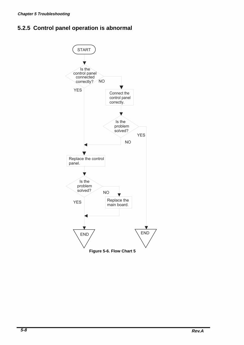
Chapter 5 Troubleshooting
Rev.A5-8
5.2.5 Control panel operation is abnormal
START
Is the control panel
connected correctly?
Connect thecontrol panelcorrectly.
Is the problemsolved?
Replace the controlpanel.
Is the problemsolved?
END
Replace themain board.
END
YES
NO
NO
YES
NO
YES
Figure 5-6. Flow Chart 5

EPSON Stylus Photo
Rev. A 5-9
5.3 Unit Repair C206 PSB/PSE BoardThis section describes the problems related to the power supply board(C206 PSB/PSE). The table belowprovides various symptoms, likely causes, and checkpoints. The checkpoints refer to waveforms,resistance, and other values to be checked to evaluate the operation of each component.
Symptom Condition Cause Checkpoint SolutionThe printerdoes notoperate at all.
+42V line isdead.
F1 is open. Check F1 by using atester.
Replace F1.
Transformer coilsare open.
Check the waveform atthe drain of Q1.
Replace T1.
Switching FET (Q1)is dead.
Check drain side. Replace Q1.
Feed backtransistor(Q2, Q3)are dead.
Check corrector side. Replace Q2or Q3.
+42 V line isabnormal.
Check following parts.• ZD87,ZD83• ZD51,ZD81•` ZD86• PC1
Replacesuitableparts.
Table 5-5. C206PSB Power Supply Borad

Chapter 5 Troubleshooting
Rev.A5-10
Table 5-6. C206PSB Power Supply Board (Continued)
Symptom Condition Cause Checkpoint Solution+5V line isdead.
IC51 (L4962E) isdead.
Check the oscillation(5-pin) and switching (7-pin) waveform of IC51.(5-pin)
(7-pin)
ReplaceIC51.

EPSON Stylus Photo
Rev. A 5-11
5.3.1 Unit Repair C209 MAIN BoardThis section describes the problems related to the main controller board(C209 MAIN). The table belowprovides various symptoms, likely causes, and checkpoints. The check points refer to waveforms,resistance, and other values to be checked to evaluate the operation of each component.
Table 5-7. Repair of the C209 MAIN Board
Symptom Condition Cause Checkpoint SolutionThe printerdoes notoperate at all.
CPU doesnot operate.
The resetcircuit isdefective.
Check the waveform ofthe +5V and /Reset signal(IC8=5,1-pin)
Replace IC8
Control ROM isnot selectedcorrectly or it’sdead.
Check if the signalwaveform at 11 pin of theIC3 can be reversed Highor Low.
Replace IC3.
RAM isdefective.
Replace RAM.
CPU isdefective.
Check the clock waveformat 27 or 28-pin of IC1.
Replace IC1 ifthe oscillationwaveform isnormal, if it isabnormal,replace theoscillator CR1.
The carriagedoes notoperatenormally.
Carriagemotor doesnot operateat all.
IC2 is defective. Check the signalwaveform at 1, 2, 23 and24 pin of IC14.
Replace IC2.
IC14 isdefective.
Check the signalwaveform at 3, 6,or 18, 21pin of IC14.
Replace IC14.

Chapter 5 Troubleshooting
Rev.A5-12
Symptom Condition Cause Checkpoint SolutionPrinting isabnormal
Printing is notexecuted or,black specks ordots appears onthe printing.
IC2 is defective. Check the outputwaveform at 7, 9 and 11pin of CN8.
Replace IC2.
Paper feedoperation isabnormal.
Paper feedmotor does notwork.
IC2 is defective. Check the outputwaveform of at 1, 2pinand 23, 24 pin of IC15.
Replace IC2
IC15 is defective. Check the outputwaveform of at 3, 6 pinor 18, 21 pin of IC15.
Replace IC15
Table 5-8.Repair of the C209 MAIN Board (Continued)

EPSON Stylus Photo
Rev. A 5-13
5.4 Repair of the Printer MechanismThis section provides instruction for repairing the printer mechanism. It describes various problems,symptom, likely causes, checkpoints, and solutions. Select appropriate symptom from the table andcheck each parts and its function as described in the checkpoint.
Symptom Condition Cause Checkpoint SolutionAbnormal pumpmechanismoperation
Abnormal PFmotor operationwhen thepower is turnedon.
Foreign substancesare loaded in the PFgears.
Manually drive thePF drive gearand check if itrotates normally.
Remove any foreignobjects.
The PF motor isdefective.(Refer to Table5-1)
Check the inner coilresistance and seeif there is anydisconnection of the coil.
Exchange the PFmotor.
Ink is notabsorbedor is poorlyabsorbed.
Used ink does notgo through thewaste ink tube.
The pump tube iscrashed.
Check the tubevisually.
Fix the crashed partby the airgun.
Capping rubber isdamaged ordeformed.
Check the cappingrubber visually.
Replace the capmechanism.
The tube is out ofthe cap.
Check if the tube is out ofthe cap visually.
Connect the tubeproperly.
Pump bulb is notclosed atabsorption.
Check the bulboperation visually.
Replace the capmechanism.
Abnormal carriageoperation.
Abnormal carriageoperation at poweron.
Foreign substancein the CR drivegear.
Check visually ifthere is anysubstances or not.
Remove any foreignsubstances.
CR motor isdefective.
Check the inner coilresistance and seeif there is anydisconnection of the coil.
Replace the CRmotor.
Abnormal carriageoperation duringprinting.
Carriage movementis not smooth.
Check whether thecarriage movessmoothly whenmoved manually.
Clean and lubricatethe carriage guideaxis.
Check tension of thetiming belt.
Adjust tensionmechanism orexchange it.
Check if there is anyforeign substancesin the carriage path.
Remove any foreignsubstances.
Printing is notperformed.
The carriagemoves, but noprinting isperformed.
Head FFC is out ofconnection.
Check if the headFFC on the board orcarriage is connectedsurely.
Connect the FFCproperly.
The FFC isdisconnectedinside.
Check the FFC by usinga tester.
Replace the FFC.
I/C is defective. Install a new I/C andperform the self-test.
Replace I/C.
Head unit isdefective.
If the condition doesnot improve evenafter 2or 3 timescleaning operation,replace the headunit and perform theself-test.
Replace the headunit.
Table 5-9. Repair of the Printer Mechanism

Chapter 5 Troubleshooting
Rev.A5-14
Symptom Condition Cause Check-point Solution
Abnormal printing Only a particular dotcauses abnormalprinting.
Print head surface isnot clean.(dot missing)
Perform the cleaningoperation severaltimes and checkprinting.
Perform thecleaning.
The head unit isdefective.
Perform the cleaningoperation severaltimes and checkprinting.
If condition does notimprove even afterthe cleaning, replacethe head.
Absorber in the capis touching the headsurface.
Check the absorberin the cap visually.
Replace theabsorber in the cap ifit is deformed.
A dot is not printedoccasionally.
Print head surfaceis not clean.(dot-missing)
Perform the cleaningoperation severaltimes and checkprinting.
Perform thecleaning.
The head FFC isdisconnected inside.
Check the FFC byusing a tester.
Replace the headFFC.
The head FFC is outof connection.
Check if the headFFC on the board orcarriage isconnected surely.
Connect the FFCproperly.
The head unit isdetective.
Perform the cleaningoperation severaltimes and checkprinting.
If condition does notimprove even afterthe cleaning, replacethe head.
I/C is defective. Install the new I/Cand perform self-test.
Replace I/C.
Black specks ordots.
The head FFC is outof connection.
Check if the headFFC on the board orcarriage isconnected surely.
Connect the FFCproperly.
The head unit isdetective.
Check connectionwith the head FFC.
Replace the head ifthere is noconnection problemwith the FFC.
A vertical line is notaligned.
Bi-directionalalignment is notadjusted.
Perform Bi-Dadjustment.
Refer to Chapter4.
White line appearsin the image data.
Head angle is notcorrect.
Perform head angleadjustment.
Refer to Chapter4.
Paper feed assemblyadjustment is notcorrect.
Perform paper feedassemblyadjustment
Refer to Chapter4.
Dot shootingdirection is tiltedbecause headsurface is not clean
Perform the cleaningoperation severaltimes and checkprinting.
Perform thecleaning operation.
I/C is defective. Install a new I/C andperform the self-test.
Replace I/C.
Head unit isdefective.
Perform the cleaningoperation severaltimes and checkprinting.
Replace the headunit.
Table 5-10. Repair of the Printer Mechanism (Continued.)

EPSON Stylus Photo
Rev. A 5-15
Symptom Condition Causes Checkpoint SolutionAbnormal paperfeeding.
Paper is not fed. Friction of the PFroller.
Check if the PFroller rotates whenpaper is not fed.
Clean the PF rollerby the cleaningsheet. Replace thePF roller if it doesnot recover.
Abnormal operationof the hopper.
Check movement ofthe ASF hoppervisually.
Replace ASF.
Malfunction of ASFdrive change-over.
Check if the ASFgear rotates visually.
Replace gears ofthe ASF drivechange-over.
Printing start point isnot right.
Friction of the PFroller.
Check if the PFroller slips duringpaper feeding.
Clean the PF rollerby the cleaningsheet. Replace thePF roller if it doesnot recover.
Printer stops duringinitialization.
Fatal error appears. ASF sensor isdefective.
Check the signallevel of the ASFsensor.(Refer toTable 5-2)
Replace ASFsensor.
PE sensor isdefective.
Check the signallevel of the PEsensor.(Refer toTable 5-2)
Replace PE sensor.
HP sensor isdefective.
Check the signallevel of the HPsensor .(Refer toTable 5-2.)
Head FFC isdisconnected.
Check if the headFFC is connected.
Connect the headFFC.
CR motor isdefective.
Check the CR motorcable is connected.
Replace the CRmotor if there is noproblem in the cableconnection.
PF motor isdefective.
Check if the PFmotor cable isconnected.
Replace the PFmotor if there is noproblem in the cableconnection.
Table 5-11. Repair of the Printer Mechanism (Continued)

Chapter 6Maintenance
6.1 OVERVIEW ............................................................................................................6-1 6.1.1 Cleaning................................................................................................................. .................. 6-1
6.1.2 Service Maintenance ...................................................................................................... ........ 6-1
6.1.3 Lubrication .............................................................................................................. ................ 6-2

Chapter 6 Maintenance
Rev. A 6-1
6.1 OVERVIEWThis section describes the points and the procedures for maintaining the printer in its optimum condition.
6.1.1 CleaningThis printer has no mechanical components requiring regular cleaning. Therefore, the points describedbelow are suggested to be checked for any dirt and make an appropriate cleaning if necessary.
� Never use the chemical solvents, such as thinner, to clean the printer. These chemicals candamage the components of the printer.
� Be careful not to damage the components when you attempt to clean the inside of the printer.
� Do not scratch surface of “ROLLER, ASSEMBLY, PF”.(Use soft brush to wipe off any dusts, or use soft cloth moistened with alcohol)
� Housing: Use clean soft cloth moistened with water and wipe off any dirt. If the housingstained with an ink, use a cloth moistened with a neutral detergent to wipe it
off.� Inside the printer: Use a vacuum cleaner to remove any paper dust.
6.1.2 Service MaintenanceIf the print irregularity (missing dot, white line, etc.) has occur or the printer indicates “MAINTENANCEERROR”, perform the following operation to clear the error.
� Head Cleaning1. The printer has a built-in head cleaning function and is executable from the control panel.2. Confirm that the printer is in stand-by state (the POWER indicator is not blinking), and hold down the
cleaning button on the control panel for more than 3 sec.3. The printer perform the built-in cleaning sequence. (during cleaning operation, the POWER indicator is
blinking) � Maintenance Error ClearSince the printer consumes the ink, not only for printing but also for another operation like cleaning,certain amount of ink are wasted. Therefore, the printer counts the amount of waste ink and they arecollected at the waste ink pad, and once the amount of waste ink reaches the predefined limit, the printerindicates “MAINTENANCE ERROR” and the waste ink pad should be replaced as follows:
1. Replace the waste ink pad to new one.2. After re-assemble the printer, turn the printer on while holding down the following buttons on the control
panel:”LOAD/EJECT” button”CLEANING” button
3. Press “LOAD/EJECT” button again while “PAPER END” indicator is blinking. This clears themaintenance error condition and the waste ink counter value stored in EEPROM of the main board.
CAUTION
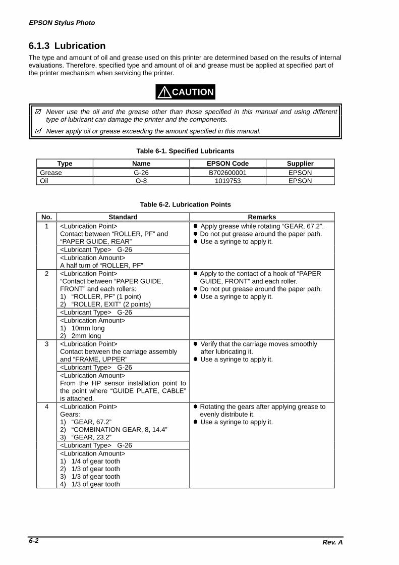
EPSON Stylus Photo
Rev. A6-2
6.1.3 LubricationThe type and amount of oil and grease used on this printer are determined based on the results of internalevaluations. Therefore, specified type and amount of oil and grease must be applied at specified part ofthe printer mechanism when servicing the printer.
� Never use the oil and the grease other than those specified in this manual and using differenttype of lubricant can damage the printer and the components.
� Never apply oil or grease exceeding the amount specified in this manual.
Type Name EPSON Code SupplierGrease G-26 B702600001 EPSONOil O-8 1019753 EPSON
No. Standard Remarks1 <Lubrication Point>
Contact between “ROLLER, PF” and“PAPER GUIDE, REAR”
� Apply grease while rotating “GEAR, 67.2”.� Do not put grease around the paper path.� Use a syringe to apply it.
<Lubricant Type> G-26<Lubrication Amount>A half turn of “ROLLER, PF”
2 <Lubrication Point>“Contact between “PAPER GUIDE,FRONT” and each rollers:1) “ROLLER, PF” (1 point)2) “ROLLER, EXIT” (2 points)
� Apply to the contact of a hook of “PAPERGUIDE, FRONT” and each roller.
� Do not put grease around the paper path.� Use a syringe to apply it.
<Lubricant Type> G-26<Lubrication Amount>1) 10mm long2) 2mm long
3 <Lubrication Point>Contact between the carriage assemblyand “FRAME, UPPER”
� Verify that the carriage moves smoothlyafter lubricating it.
� Use a syringe to apply it.<Lubricant Type> G-26<Lubrication Amount>From the HP sensor installation point tothe point where “GUIDE PLATE, CABLE”is attached.
4 <Lubrication Point>Gears:1) “GEAR, 67.2”2) “COMBINATION GEAR, 8, 14.4”3) “GEAR, 23.2”
� Rotating the gears after applying grease toevenly distribute it.
� Use a syringe to apply it.
<Lubricant Type> G-26<Lubrication Amount>1) 1/4 of gear tooth2) 1/3 of gear tooth3) 1/3 of gear tooth4) 1/3 of gear tooth
CAUTION
Table 6-1. Specified Lubricants
Table 6-2. Lubrication Points

Chapter 6 Maintenance
Rev. A 6-3
No. Standard Remarks5 <Lubrication Point>
The shaft for “GEAR, 16, 40.8” at“FRAME, LEFT”
� Use a syringe to apply it.
<Lubricant Type> G-26<Lubrication Amount>Approx. 5mm long
6 <Lubrication Point>Bush for “ROLER, PF”1) Left: Inside the bush2) Right: Inside the bush (near the
pump assembly)
� When applying to the right bush, apply itfrom the side of the paper path and wipe offany grease stick out to the cap assemblyside.
� Rotate “ROLLER, PF” after applying thegrease to evenly distribute it in the bush.
� Use a syringe to apply it.<Lubricant Type> G-26<Lubrication Amount>Approx. 3mm diametrically
7 <Lubrication Point>Both Left/Right Bush for “ROLLER, EXIT”
� Do not put grease around the paper path.� Use a syringe to apply it.
<Lubricant Type> G-26<Lubrication Amount>Evenly apply inside the bush
8 <Lubrication Point>Contact between “HOLDER, PULLEY,DRIVEN” and “FRAME, UPPER”
� Verify that the holder slides only with aspring force after applying the grease.
� Use a syringe to apply it.
<Lubricant Type> G-26<Lubrication Amount>2mm long at each specified point
9 <Lubrication Point>ASF;A round hole of the right frame of ASF (tohold the roller shaft)
� Do not put grease to “ROLLER,ASSEMBLY, LD”.
<Lubricant Type> G-26<Lubrication Amount>Evenly apply inside the hole
10 <Lubrication Point>ASF;Contact between “HOPPER” and “LEVER,HOPPER, RELEASE”
� Completely wipe off any grease stack out toinner side of ASF.
<Lubricant Type> G-26<Lubrication Amount>Evenly apply to the contact
Table 6-3. Lubrication Points (Continued)

EPSON Stylus Photo
Rev. A6-4
No. Standard Remarks11 <Lubrication Point>
A round hole of the left frame of ASF(“GEAR, 34” is inserting to this hole)
� Completely wipe off any grease stack out toinner side of ASF.
<Lubricant Type> G-26<Lubrication Amount>Evenly apply inside the hole
12 <Lubrication Point>Oil pad of carriage assembly
� This application must be made only when;*Replacing the carriage assembly*Replacing oil pad
� Use a precise syringe to apply it. Ifaccidentally apply too much oil to oil pad,thrown it away and take a new oil pad again.
� Leave oil pad for a while to wait until oil isevenly infiltrate and install it on the carriageassembly.
<Lubricant Type> O-8<Lubrication Amount>0.6cc
Note that This is an amount to be appliednew oil pad when replacing it.
� Never apply oil to the CR guide shaft directly or additionally to the oil pad. This maycause fatal damage to the components of the printer.
Table 6-4. Lubrication Points (Continued)
WARNING
No.12(Oil pad)
*Never apply the oil exceeding 0.6cc.
Carriage Assembly(bottom view)
"SHAFT, CR, GUIDE"

Chapter 6 Maintenance
Rev. A 6-5
No.3
No.11
"GEAR, 34"
No.1
No.2
10mm
2mm
2mm

EPSON Stylus Photo
Rev. A6-6
No.5
No.4
No.4
No.4
"GEAR, 23.2"
"GEAR, 16, 40.8"
"GEAR, 67.2"
"COMBINATION GEAR, 8, 14.4"
No.6
No.7

Chapter 6 Maintenance
Rev. A 6-7
No.9
No.10
"HOPPER, ASSEMBLY"
"FRAME, ASF"
No.8
"HOLDER, PULLEY, DRIVEN"

Appendix
A.1 Connector Summary........................................................................................... A-1
A.2 Connector Summary........................................................................................... A-2
A.3 EEPROM Address Map ....................................................................................... A-4
A.4 Circuit Board Component Layouts .................................................................... A-8
A.5 Exploded Diagrams........................................................................................... A-12
A.6 Circuit Diagrams ............................................................................................... A-15

EPSON Stylus Photo
Rev.A A-1
A.1 Connector Summary
EPSON Stylus Photo has the following primary component units;
• Main Board(C209 Main)
• Power Supply Board (C206 PSB/PSE)
• Printer Mechanism
Figure A-1 below illustrates how these component units are connected.
CN1
C206PSB/PSE(Power Supply Board)
CN2
AC
CN10 CN3
CN8
C209 MAIN(Main Board)
CN1
CN2
CN6
CN7
CN11 CN5 CN4
Control Panel
Print Head
CRMotor
PFMotor
ASF Sensor
HP Sensor
PE Sensor
Parallel I/F
Serial I/F
Printer Mechanism
Figure A-1. Cable Connection

Appendix
Rev. AA-2
A.2 Connector Summary
Following tables show connector pin assignment of the C209 main board.
Connector Function Table to referCN1 Parallel I/F connector Chapter1/Table 1-9CN2 Serial I/F connector Chapter1/Table 1-15CN3 ⇒Control panel Table A-2CN4 ⇒PE sensor Table A-3CN5 ⇒HP sensor Table A-4CN6 ⇒CR motor Table A-5CN7 ⇒PF motor Table A-6CN8 ⇒Print head Table A-7CN10 ⇒Power supply board (C206 PSB) Table A-8CN11 ⇒ASF sensor Table A-9
Pin Signal Name I/O Function1 LED0 Out LED drive signal (0)2 GND ---- Ground3 LED1 Out LED drive signal (1)4 GND ---- Ground5 LED2 Out LED drive signal (2)6 +5V ---- Logic power supply7 +5V ---- Logic power supply8 LED4 Out LED drive signal (4)9 SW1 In Panel switch input (1)10 PSC In Power on/off switch11 SW0 In Panel switch on/off (0)12 SW2 In Panel switch on/off (2)
Pin Signal Name I/O Function1 PE In Sensor detect signal2 GND --- Ground3 PEV --- Sensor power supply(+5V)
Pin Signal Name I/O Function1 HP In Sensor detect signal2 GND --- Ground3 HPV --- Sensor power supply(+5V)
Pin Signal Name I/O Function1 CRA Out Phase drive signal(A)2 CR-A Out Phase drive signal (-A)3 CRB Out Phase drive signal (B)4 CR-B Out Phase drive signal(-B)
Table A-1. Connector summary of the C209 Main board
Table A-2. Connector CN3
Table A-3. Connector CN4
Table A-4. Connector CN5
Table A-5. Connector CN6
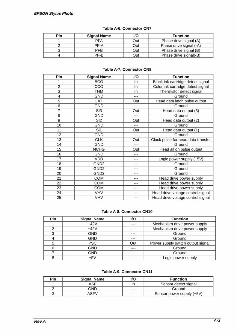
EPSON Stylus Photo
Rev.A A-3
Pin Signal Name I/O Function1 PFA Out Phase drive signal (A)2 PF-A Out Phase drive signal (-A)3 PFB Out Phase drive signal (B)4 PF-B Out Phase drive signal(-B)
Pin Signal Name I/O Function1 BCO In Black ink cartridge detect signal2 CCO In Color ink cartridge detect signal3 THM In Thermistor detect signal4 GND --- Ground5 LAT Out Head data latch pulse output6 GND --- Ground7 SI3 Out Head data output (3)8 GND --- Ground9 SI2 Out Head data output (2)10 GND --- Ground11 Sl1 Out Head data output (1)12 GND --- Ground13 CLK Out Clock pulse for head data transfer14 GND --- Ground15 NCHG Out Head all on pulse output16 GND --- Ground17 VDD --- Logic power supply (+5V)18 GND2 --- Ground19 GND2 --- Ground20 GND2 --- Ground21 COM --- Head drive power supply22 COM --- Head drive power supply23 COM --- Head drive power supply24 VHV --- Head drive voltage control signal25 VHV --- Head drive voltage control signal
Pin Signal Name I/O Function1 +42V --- Mechanism drive power supply2 +42V --- Mechanism drive power supply3 GND --- Ground4 GND --- Ground5 PSC Out Power supply switch output signal6 GND ---- Ground7 GND --- Ground8 +5V --- Logic power supply
Pin Signal Name I/O Function1 ASF In Sensor detect signal2 GND --- Ground3 ASFV --- Sensor power supply (+5V)
Table A-6. Connector CN7
Table A-7. Connector CN8
Table A-8. Connector CN10
Table A-9. Connector CN11

Appendix
Rev. AA-4
A.3 EEPROM Address Map
Address Explanation Setting QPITSettings
FactorySettings
00H Password 0 54H -01H 0FH -02H Market 0: World / 1:Japan
2: Custom(MJ-) ∗∗3: Custom(Stylus Color) ∗∗4: Custom (other name) ∗∗
00H (∗1)(∗3)
03H 1st dot adjustment -40≤ n ≤40 (by 1/1440 inch) 00H (∗1)04H Bi-D adjustment data -36≤ n ≤36 (by 1/1440 inch) 00H (∗1)05H Uni-D adjustment -36≤ n ≤36 (by 1/1440 inch) 00H (∗1)06H Reserved 00H -07H Reserved 00H -08H Carriage speed adjustment
data-4≤ n ≤4 (by G.A timer unit) 00H (∗1)
09H Reserved 00H -0AH Head actuator rank ID for
VhN12H (∗1)
0BH Head actuator rank ID forTwh2
01H (∗1)
0CH Head actuator rank ID forVhM
10H (∗1)
0DH Reserved 00H -0EH Reserved 00H -0FH Reserved 00H -10H Password 1 5AH -11H 0FH -12H Custom EEPROM sub
number00H 00H
13H 00H 00H14H 00H 00H15H 00H 00H16H Reserved 00H -17H Reserved 00H -18H CPSI password 00H 00H19H 00H 00H1AH 00H 00H1BH 00H 00H1CH CPSI flags bit7: CPSI license
0:Disable 1:Enablebit6: CPSI Font license 0:Disable 1:Enable
00H 00H
1DH Reserved 00H -1EH Reserved 00H -1FH EEPROM Revision 42H -20H Password 2 5AH -21H 0FH -22H Interface selection 0: Auto / 1: Parallel
2: Serial00H 00H∗2
Note) ∗∗: Change model name for IEEE1284 device ID return.∗1: Adjusted at factory.∗2: Initialized after performed panel initialization of EEPROM.∗3: Factory setting for Korean version is mentioned in the page A-7.

EPSON Stylus Photo
Rev.A A-5
Address Explanation Setting QPITsettings
Factorysettings
23H Interface wait time 0 to 255 (by second) 0AH 0AH24H Parallel I/F speed 0:High speed 1:Normal 00H 00H25H Reserved 00H -26H Reserved 00H -27H Print direction control 0: Bi-D 1: Uni-D 2: Auto 02H 02H28H CG table 0: PC437 1: PC850 00H (∗1)29H Reserved 00H -2AH Auto LF/Network I/F mode bit1: Network I/F mode (0=off, 1=on)
bit0: Auto line feed (0=off, 1=on)00H 00H
2BH Panel mask function bit5: Extended settingsbit2: Cleaningbit1: Replace I/Cbit0: Load/Eject
00H 00H∗3
2CH Reserved 00H -2DH Reserved 00H -2EH Reserved 00H -2FH Reserved 00H -30H Password 3 5AH -31H 0FH -32H Reserved 00H -33H Reserved 00H -34H Top margin 42 to 44X360 (by 1/360 inch) 78H 78H∗335H 00H 00H∗336H Reserved 00H -37H Reserved 00H -38H Reserved 00H -39H Reserved 00H -3AH Reserved 00H -3BH Reserved 00H -3CH Reserved 00H -3DH Reserved 00H -3EH CR-phase of Home 00H 00H3FH ERROR Number 00H 00H40H Password 4 5AH -41H 0FH -42H Ink flags bit7: reserved
bit6: black “one time”bit5: color “one time”bit4: Initial charge requiredbit3: reservedbit2: in cleaning sequencebit1: black CL requiredbit0: color CL required
00H 10H
43H Ink flags 2 bit2: YMC cartridge changed and cleaned 0: first cartridge 1: changedbit1: Black cartridge changed and cleaned 0: first cartridge 1: changedbit0: Black cartridge changed and cleaned 0: with YMC cartridge 1: alone
00H 00H

Appendix
Rev. AA-6
Address Explanation Settings QPITsettings
Factorysettings
44H Ink Counter Cb(total)1count=100(ng)
00H 00H
45H 00H 00H46H 00H 00H47H 00H 00H48H Ink counter CY(total)
1count=100(ng)00H 00H
49H 00H 00H4AH 00H 00H4BH 00H 00H4CH Ink counter Cm(total)
1count=100(ng)00H 00H
4DH 00H 00H4EH 00H 00H4FH 00H 00H50H Password 5 5AH -51H 0FH -52H Ink counter Cc(total)
1count=100(ng)00H 00H
53H 00H 00H54H 00H 00H55H 00H 00H56H Ink counter Csm(total)
1count=100(ng)00H 00H
57H 00H 00H58H 00H 00H59H 00H 00H5AH Ink counter Csc(total)
1count=100(ng)00H 00H
5BH 00H 00H5CH 00H 00H5DH 00H 00H5EH Reserved 00H -5FH Reserved 00H -60H Password 6 5AH -61H 0FH -62H Ink counter Rb 00H 00H63H 00H 00H64H Ink counter Ry 00H 00H65H 00H 00H66H Ink counter A 00H 00H∗267H 00H 00H∗268H power off time 00H 00H∗269H 00H 00H∗26AH CL time 00H 00H∗26BH 00H 00H∗26CH accumulated printing time 00H 00H6DH 1 count = 1 minute 00H 00H6EH Reserved 00H -6FH Reserved 00H -

EPSON Stylus Photo
Rev.A A-7
Address Explanation Setting QPITsettings
Factorysettings
70H Password 7 5AH -71H 0FH -72H customized model name strings counter 00H 00H73H strings of model field for Device 00H 00H74H ID 00H 00H75H 00H 00H76H 00H 00H77H 00H 00H78H 00H 00H79H 00H 00H7AH 00H 00H7BH 00H 00H7CH 00H 00H7DH 00H 00H7EH 00H 00H7FH 00H 00H
[∗3: Specifications for Korean Version]
1) EEPROM factory setting for Korean version.
Address Explanation Korea Factory Settings02H Market 80H2BH Panel mask function 80H34H Top margin 2AH35H 00H
2) IEEE1284 Device ID [00H] [56H] MFG:EPSON; CMD:ESCPL2, BDC; MDL:Stylus[SP]Photo; CLS:PRINTER; DES:EPSON/TriGem[SP]Stylus[SP]Photo; 3) BCD-ID command reply @EJL<SP>ID<CR><LF> MFG:EPSON; CMD:ESCPL2,BDC; MDL:Stylus[SP]Photo; CLS:PRINTER; DES:EPSON/TriGem[SP]Stylus[SP]Photo; <FF>

Appendix
Rev. AA-8
A.4 Circuit Board Component Layouts
Figure A-2.C209 Component Layout

EPSON Stylus Photo
Rev.A A-9
Figure A-3. C206PSB Component Layout

Appendix
Rev. AA-10
Figure A-4. C206PSE Board Component Layout
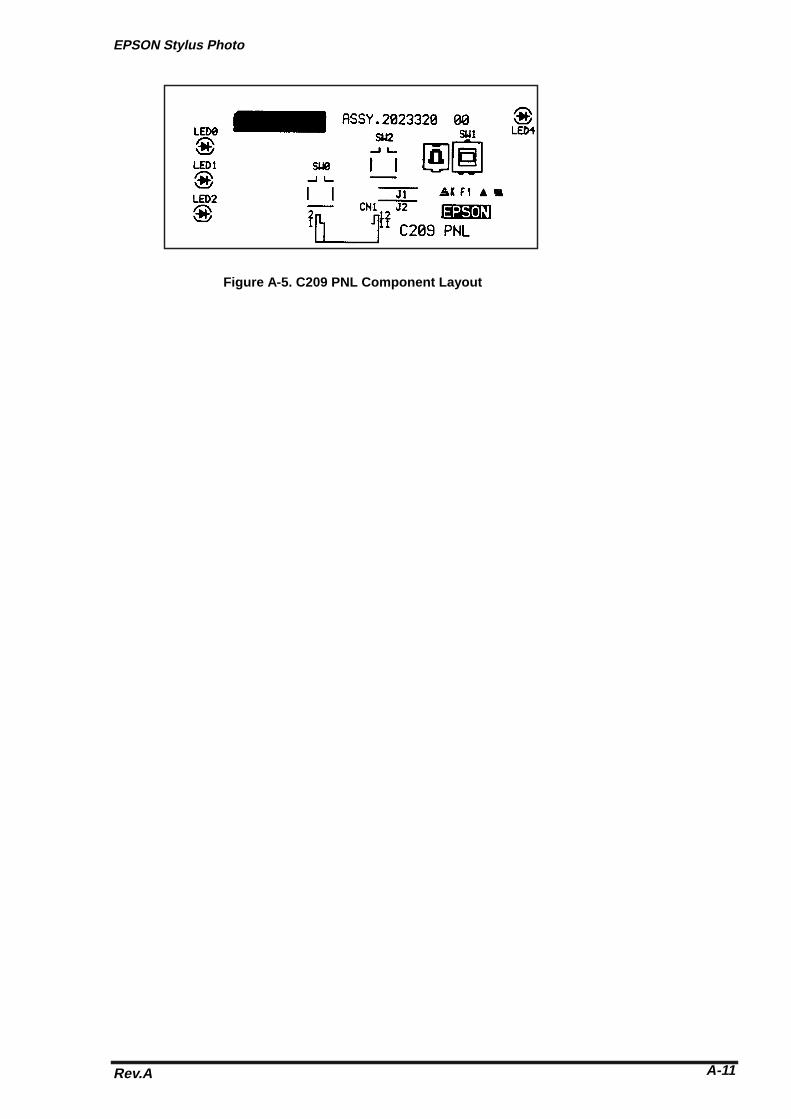
EPSON Stylus Photo
Rev.A A-11
Figure A-5. C209 PNL Component Layout

Appendix
Rev. AA-12
A.5 Exploded Diagrams
Figure A-6. EPSON Stylus Photo Exploded Diagram (1)

EPSON Stylus Photo
Rev.A A-13
Figure A-7. EPSON Stylus Photo Exploded Diagram (2)

Appendix
Rev. AA-14
Figure A-8. EPSON Stylus Photo Exploded Diagram (3)

EPSON Stylus Photo
Rev.A A-15
A.6 Circuit Diagrams
Figure A-9. C206PSB Board Circuit Diagram
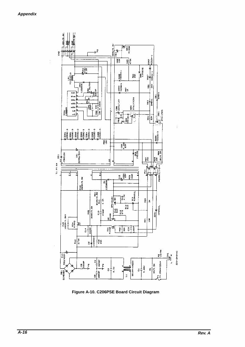
Appendix
Rev. AA-16
Figure A-10. C206PSE Board Circuit Diagram

EPSON OVERSEAS MARKETING LOCATIONS
EPSON AMERICA, Inc.
20770 Madrona Avenue,P.O. Box 2842Torrance, CA 90509-2842Phone: (800)922-8911Fax: (310)782-5220
EPSON DEUTCHLAND GmBH
Zülpicher Straße 6, 4549 DüsseldorfGermany
Phone: (0211)56030Telex: 8584786
EPSON UK LTD.
Campus 100, Maylands Avenue,Hemel Hempstead, Herts, HP2 7TJU.K.Phone: (+44)01442-61144Fax: (+44)01442-227227
EPSON FRANCE S.A.
68 bis, rue Marjolin 92300,Levallois-PerretFrancePhone: (1)4087-3737Telex: 610657
EPSON IBERICA, S.A.
Avda. de Roma, 18-2608290 Cerdanyola del VallesBalcerona, SpainPhone: 582.15.00Fax: 582.15.55
EPSON ITALIA S.P.A.
V. le F. lli Casiraghi, 42720099 Sesto S. Giovanni MIItalyPhone: 2-262331Fax: 2-2440750
EPSON AUSTRALIA PTY. LIMITED
1/70 Gibbes Street,Chatswood 2067 NSWAustraliaPhone: 2-9903-9000Fax: 2-9903-9177
EPSON SINGAPORE PTE. LTD.
No.1 Temasek Avenue #36-00Millenia TowerSingapore 039192Phone: (065)3377911Fax: (065)3341185
EPSON HONG KONG LTD.
Rooms 4706-10, 47/FChina Resource Bldg.26 Harbour Road, Wanchai, Hong KongPhone: 2585-4300Fax: 2827-7083
EPSON TAIWAN TECHNOLOGY &TRADING LTD.
10F, No. 287 Nonking E. Road, Sec. 3,Taipei, Taiwan, R.O.C.Phone: (02)717-7360Fax: (02)712-9164
EPSON PORTUGAL, S.A.
R. do Progresso, 471, 1° Perafita4460 Matosinhos, Portugal
Phone: (02)996 14 02Fax: (02)996 14 11SEIKO EPSON CORPORATIONImaging & Information Products Division
80 Harashinden, Hirooka, Shiojiri-Shi, Nagano-Ken 399-07 JAPANPhone: 0263-52-2552Fax: 0263-54-4007
As of September, 1996

EPSONSEIKO EPSON CORPORATION